US9737421B2 - Blood-flow tubing - Google Patents
Blood-flow tubingDownload PDFInfo
- Publication number
- US9737421B2 US9737421B2US13/345,628US201213345628AUS9737421B2US 9737421 B2US9737421 B2US 9737421B2US 201213345628 AUS201213345628 AUS 201213345628AUS 9737421 B2US9737421 B2US 9737421B2
- Authority
- US
- United States
- Prior art keywords
- tubing
- helical
- flow
- internal helical
- internal
- Prior art date
- Legal status (The legal status is an assumption and is not a legal conclusion. Google has not performed a legal analysis and makes no representation as to the accuracy of the status listed.)
- Expired - Fee Related, expires
Links
- 230000017531blood circulationEffects0.000titleclaimsabstractdescription17
- 230000001939inductive effectEffects0.000claimsdescription25
- 238000000034methodMethods0.000claimsdescription21
- 230000015572biosynthetic processEffects0.000claimsdescription9
- 230000001965increasing effectEffects0.000claimsdescription7
- 239000008280bloodSubstances0.000claimsdescription6
- 210000004369bloodAnatomy0.000claimsdescription6
- 239000000411inducerSubstances0.000abstract2
- 239000000463materialSubstances0.000description9
- 239000007788liquidSubstances0.000description7
- 238000013461designMethods0.000description6
- 238000002595magnetic resonance imagingMethods0.000description5
- 238000005259measurementMethods0.000description5
- 210000001367arteryAnatomy0.000description4
- 238000000502dialysisMethods0.000description4
- 239000012530fluidSubstances0.000description4
- 210000000748cardiovascular systemAnatomy0.000description3
- 229940000032cardiovascular system drugDrugs0.000description3
- 238000005266castingMethods0.000description3
- 230000000694effectsEffects0.000description3
- 239000007943implantSubstances0.000description3
- 230000002792vascularEffects0.000description3
- 201000001320AtherosclerosisDiseases0.000description2
- 238000002583angiographyMethods0.000description2
- 230000008901benefitEffects0.000description2
- 230000004087circulationEffects0.000description2
- 230000015271coagulationEffects0.000description2
- 238000005345coagulationMethods0.000description2
- 238000012790confirmationMethods0.000description2
- 238000010276constructionMethods0.000description2
- 230000003247decreasing effectEffects0.000description2
- 238000003780insertionMethods0.000description2
- 230000037431insertionEffects0.000description2
- 239000002184metalSubstances0.000description2
- 238000002156mixingMethods0.000description2
- 239000003921oilSubstances0.000description2
- 239000000523sampleSubstances0.000description2
- 239000002002slurrySubstances0.000description2
- 239000007787solidSubstances0.000description2
- 238000001356surgical procedureMethods0.000description2
- 239000000725suspensionSubstances0.000description2
- 239000012815thermoplastic materialSubstances0.000description2
- JOYRKODLDBILNP-UHFFFAOYSA-NEthyl urethaneChemical compoundCCOC(N)=OJOYRKODLDBILNP-UHFFFAOYSA-N0.000description1
- 239000004721Polyphenylene oxideSubstances0.000description1
- 208000007536ThrombosisDiseases0.000description1
- 238000002399angioplastyMethods0.000description1
- 230000002238attenuated effectEffects0.000description1
- 230000009286beneficial effectEffects0.000description1
- 229920000249biocompatible polymerPolymers0.000description1
- 210000004204blood vesselAnatomy0.000description1
- 230000036760body temperatureEffects0.000description1
- 238000001125extrusionMethods0.000description1
- 239000000835fiberSubstances0.000description1
- 235000013305foodNutrition0.000description1
- 230000006870functionEffects0.000description1
- 230000001435haemodynamic effectEffects0.000description1
- 206010020718hyperplasiaDiseases0.000description1
- 238000003384imaging methodMethods0.000description1
- 238000002513implantationMethods0.000description1
- 238000001727in vivoMethods0.000description1
- 230000006698inductionEffects0.000description1
- 238000012986modificationMethods0.000description1
- 230000004048modificationEffects0.000description1
- 230000008506pathogenesisEffects0.000description1
- 230000002093peripheral effectEffects0.000description1
- 229920000570polyetherPolymers0.000description1
- 230000002035prolonged effectEffects0.000description1
- 230000000541pulsatile effectEffects0.000description1
- 230000009467reductionEffects0.000description1
- 235000015067saucesNutrition0.000description1
- 238000004062sedimentationMethods0.000description1
- 235000014347soupsNutrition0.000description1
- 229920001059synthetic polymerPolymers0.000description1
- 229920001169thermoplasticPolymers0.000description1
- 239000004416thermosoftening plasticSubstances0.000description1
- 238000002604ultrasonographyMethods0.000description1
Images

Classifications
- A—HUMAN NECESSITIES
- A61—MEDICAL OR VETERINARY SCIENCE; HYGIENE
- A61F—FILTERS IMPLANTABLE INTO BLOOD VESSELS; PROSTHESES; DEVICES PROVIDING PATENCY TO, OR PREVENTING COLLAPSING OF, TUBULAR STRUCTURES OF THE BODY, e.g. STENTS; ORTHOPAEDIC, NURSING OR CONTRACEPTIVE DEVICES; FOMENTATION; TREATMENT OR PROTECTION OF EYES OR EARS; BANDAGES, DRESSINGS OR ABSORBENT PADS; FIRST-AID KITS
- A61F2/00—Filters implantable into blood vessels; Prostheses, i.e. artificial substitutes or replacements for parts of the body; Appliances for connecting them with the body; Devices providing patency to, or preventing collapsing of, tubular structures of the body, e.g. stents
- A61F2/82—Devices providing patency to, or preventing collapsing of, tubular structures of the body, e.g. stents
- A61F2/844—Devices providing patency to, or preventing collapsing of, tubular structures of the body, e.g. stents folded prior to deployment
- A—HUMAN NECESSITIES
- A61—MEDICAL OR VETERINARY SCIENCE; HYGIENE
- A61F—FILTERS IMPLANTABLE INTO BLOOD VESSELS; PROSTHESES; DEVICES PROVIDING PATENCY TO, OR PREVENTING COLLAPSING OF, TUBULAR STRUCTURES OF THE BODY, e.g. STENTS; ORTHOPAEDIC, NURSING OR CONTRACEPTIVE DEVICES; FOMENTATION; TREATMENT OR PROTECTION OF EYES OR EARS; BANDAGES, DRESSINGS OR ABSORBENT PADS; FIRST-AID KITS
- A61F2/00—Filters implantable into blood vessels; Prostheses, i.e. artificial substitutes or replacements for parts of the body; Appliances for connecting them with the body; Devices providing patency to, or preventing collapsing of, tubular structures of the body, e.g. stents
- A61F2/02—Prostheses implantable into the body
- A61F2/04—Hollow or tubular parts of organs, e.g. bladders, tracheae, bronchi or bile ducts
- A61F2/06—Blood vessels
- A—HUMAN NECESSITIES
- A61—MEDICAL OR VETERINARY SCIENCE; HYGIENE
- A61F—FILTERS IMPLANTABLE INTO BLOOD VESSELS; PROSTHESES; DEVICES PROVIDING PATENCY TO, OR PREVENTING COLLAPSING OF, TUBULAR STRUCTURES OF THE BODY, e.g. STENTS; ORTHOPAEDIC, NURSING OR CONTRACEPTIVE DEVICES; FOMENTATION; TREATMENT OR PROTECTION OF EYES OR EARS; BANDAGES, DRESSINGS OR ABSORBENT PADS; FIRST-AID KITS
- A61F2/00—Filters implantable into blood vessels; Prostheses, i.e. artificial substitutes or replacements for parts of the body; Appliances for connecting them with the body; Devices providing patency to, or preventing collapsing of, tubular structures of the body, e.g. stents
- A61F2/82—Devices providing patency to, or preventing collapsing of, tubular structures of the body, e.g. stents
- A61F2/86—Stents in a form characterised by the wire-like elements; Stents in the form characterised by a net-like or mesh-like structure
- A61F2/90—Stents in a form characterised by the wire-like elements; Stents in the form characterised by a net-like or mesh-like structure characterised by a net-like or mesh-like structure
- A—HUMAN NECESSITIES
- A61—MEDICAL OR VETERINARY SCIENCE; HYGIENE
- A61F—FILTERS IMPLANTABLE INTO BLOOD VESSELS; PROSTHESES; DEVICES PROVIDING PATENCY TO, OR PREVENTING COLLAPSING OF, TUBULAR STRUCTURES OF THE BODY, e.g. STENTS; ORTHOPAEDIC, NURSING OR CONTRACEPTIVE DEVICES; FOMENTATION; TREATMENT OR PROTECTION OF EYES OR EARS; BANDAGES, DRESSINGS OR ABSORBENT PADS; FIRST-AID KITS
- A61F2/00—Filters implantable into blood vessels; Prostheses, i.e. artificial substitutes or replacements for parts of the body; Appliances for connecting them with the body; Devices providing patency to, or preventing collapsing of, tubular structures of the body, e.g. stents
- A61F2/02—Prostheses implantable into the body
- A61F2/04—Hollow or tubular parts of organs, e.g. bladders, tracheae, bronchi or bile ducts
- A61F2/06—Blood vessels
- A61F2002/065—Y-shaped blood vessels
- A—HUMAN NECESSITIES
- A61—MEDICAL OR VETERINARY SCIENCE; HYGIENE
- A61F—FILTERS IMPLANTABLE INTO BLOOD VESSELS; PROSTHESES; DEVICES PROVIDING PATENCY TO, OR PREVENTING COLLAPSING OF, TUBULAR STRUCTURES OF THE BODY, e.g. STENTS; ORTHOPAEDIC, NURSING OR CONTRACEPTIVE DEVICES; FOMENTATION; TREATMENT OR PROTECTION OF EYES OR EARS; BANDAGES, DRESSINGS OR ABSORBENT PADS; FIRST-AID KITS
- A61F2/00—Filters implantable into blood vessels; Prostheses, i.e. artificial substitutes or replacements for parts of the body; Appliances for connecting them with the body; Devices providing patency to, or preventing collapsing of, tubular structures of the body, e.g. stents
- A61F2/02—Prostheses implantable into the body
- A61F2/04—Hollow or tubular parts of organs, e.g. bladders, tracheae, bronchi or bile ducts
- A61F2/06—Blood vessels
- A61F2002/068—Modifying the blood flow model, e.g. by diffuser or deflector
- A—HUMAN NECESSITIES
- A61—MEDICAL OR VETERINARY SCIENCE; HYGIENE
- A61F—FILTERS IMPLANTABLE INTO BLOOD VESSELS; PROSTHESES; DEVICES PROVIDING PATENCY TO, OR PREVENTING COLLAPSING OF, TUBULAR STRUCTURES OF THE BODY, e.g. STENTS; ORTHOPAEDIC, NURSING OR CONTRACEPTIVE DEVICES; FOMENTATION; TREATMENT OR PROTECTION OF EYES OR EARS; BANDAGES, DRESSINGS OR ABSORBENT PADS; FIRST-AID KITS
- A61F2230/00—Geometry of prostheses classified in groups A61F2/00 - A61F2/26 or A61F2/82 or A61F9/00 or A61F11/00 or subgroups thereof
- A61F2230/0002—Two-dimensional shapes, e.g. cross-sections
- A61F2230/0017—Angular shapes
- A—HUMAN NECESSITIES
- A61—MEDICAL OR VETERINARY SCIENCE; HYGIENE
- A61F—FILTERS IMPLANTABLE INTO BLOOD VESSELS; PROSTHESES; DEVICES PROVIDING PATENCY TO, OR PREVENTING COLLAPSING OF, TUBULAR STRUCTURES OF THE BODY, e.g. STENTS; ORTHOPAEDIC, NURSING OR CONTRACEPTIVE DEVICES; FOMENTATION; TREATMENT OR PROTECTION OF EYES OR EARS; BANDAGES, DRESSINGS OR ABSORBENT PADS; FIRST-AID KITS
- A61F2230/00—Geometry of prostheses classified in groups A61F2/00 - A61F2/26 or A61F2/82 or A61F9/00 or A61F11/00 or subgroups thereof
- A61F2230/0063—Three-dimensional shapes
- A61F2230/0091—Three-dimensional shapes helically-coiled or spirally-coiled, i.e. having a 2-D spiral cross-section
- Y—GENERAL TAGGING OF NEW TECHNOLOGICAL DEVELOPMENTS; GENERAL TAGGING OF CROSS-SECTIONAL TECHNOLOGIES SPANNING OVER SEVERAL SECTIONS OF THE IPC; TECHNICAL SUBJECTS COVERED BY FORMER USPC CROSS-REFERENCE ART COLLECTIONS [XRACs] AND DIGESTS
- Y10—TECHNICAL SUBJECTS COVERED BY FORMER USPC
- Y10T—TECHNICAL SUBJECTS COVERED BY FORMER US CLASSIFICATION
- Y10T428/00—Stock material or miscellaneous articles
- Y10T428/13—Hollow or container type article [e.g., tube, vase, etc.]
- Y10T428/1352—Polymer or resin containing [i.e., natural or synthetic]
- Y10T428/1355—Elemental metal containing [e.g., substrate, foil, film, coating, etc.]
- Y—GENERAL TAGGING OF NEW TECHNOLOGICAL DEVELOPMENTS; GENERAL TAGGING OF CROSS-SECTIONAL TECHNOLOGIES SPANNING OVER SEVERAL SECTIONS OF THE IPC; TECHNICAL SUBJECTS COVERED BY FORMER USPC CROSS-REFERENCE ART COLLECTIONS [XRACs] AND DIGESTS
- Y10—TECHNICAL SUBJECTS COVERED BY FORMER USPC
- Y10T—TECHNICAL SUBJECTS COVERED BY FORMER US CLASSIFICATION
- Y10T428/00—Stock material or miscellaneous articles
- Y10T428/13—Hollow or container type article [e.g., tube, vase, etc.]
- Y10T428/1352—Polymer or resin containing [i.e., natural or synthetic]
- Y10T428/1362—Textile, fabric, cloth, or pile containing [e.g., web, net, woven, knitted, mesh, nonwoven, matted, etc.]
- Y—GENERAL TAGGING OF NEW TECHNOLOGICAL DEVELOPMENTS; GENERAL TAGGING OF CROSS-SECTIONAL TECHNOLOGIES SPANNING OVER SEVERAL SECTIONS OF THE IPC; TECHNICAL SUBJECTS COVERED BY FORMER USPC CROSS-REFERENCE ART COLLECTIONS [XRACs] AND DIGESTS
- Y10—TECHNICAL SUBJECTS COVERED BY FORMER USPC
- Y10T—TECHNICAL SUBJECTS COVERED BY FORMER US CLASSIFICATION
- Y10T428/00—Stock material or miscellaneous articles
- Y10T428/13—Hollow or container type article [e.g., tube, vase, etc.]
- Y10T428/1352—Polymer or resin containing [i.e., natural or synthetic]
- Y10T428/139—Open-ended, self-supporting conduit, cylinder, or tube-type article
- Y—GENERAL TAGGING OF NEW TECHNOLOGICAL DEVELOPMENTS; GENERAL TAGGING OF CROSS-SECTIONAL TECHNOLOGIES SPANNING OVER SEVERAL SECTIONS OF THE IPC; TECHNICAL SUBJECTS COVERED BY FORMER USPC CROSS-REFERENCE ART COLLECTIONS [XRACs] AND DIGESTS
- Y10—TECHNICAL SUBJECTS COVERED BY FORMER USPC
- Y10T—TECHNICAL SUBJECTS COVERED BY FORMER US CLASSIFICATION
- Y10T428/00—Stock material or miscellaneous articles
- Y10T428/13—Hollow or container type article [e.g., tube, vase, etc.]
- Y10T428/1352—Polymer or resin containing [i.e., natural or synthetic]
- Y10T428/1397—Single layer [continuous layer]
Definitions
- This inventionrelates inter alia to artificial or modified natural blood-flow tubing, by which is meant artificial vascular prostheses or modified natural grafts or autografts, and tubing in which blood flows outside the body, e.g. in dialysis or in open heart surgery.
- the inventionmight well extend to any tubing that carries a laminar flow, and particularly, but by no means exclusively, a pulsatile flow.
- the inventioncomprises, in one aspect, tubing, especially, but not exclusively artificial or modified natural blood flow tubing, having helical-flow inducing means adapted to induce helical flow in such fashion as to eliminate or reduce turbulence.
- the tubingmay have internal helical grooving and/or ridging, which may be multi-start grooving and/or ridging.
- the grooves and ridgesmay be of any cross-sectional shape and size, for example semicircular, square, triangular or sinusoidal—some may be found more effective than others in particular circumstances.
- helicalas used herein is meant “generally helical”, rather than necessarily always mathematically precisely helical.
- the tubingmay be of non-circular cross-section, twisted.
- Synthetic or other thermoplastic or plastifiable and re-settable materialmade as a straight, circular or non-circular cross-section tube, may be plastified and reset in twisted or corkscrew condition.
- Non-circularcan, of course, include, elliptical, semi-circular, triangular, square or any other convenient or appropriate shape, including shapes with wavy peripheries which, when twisted, will form grooves and/or ridges.
- the helical formationmay have a constant helix angle along at least a part of its length, or one which reduces or increases over at least part of its length.
- the grooving and/or ridging, where present,may taper in the direction of flow or in the opposite direction.
- the helical formationmay have a helix angle between 5° and 50°, for example, about 16°.
- a helical formation having an increasing or reducing helix angle over at least a part of its lengthmay have an angle of 16°, for example, at the start or the finish of the taper, or somewhere in between. Angles outwith the suggested range may be found useful, but it is thought the angles above 50° will unduly restrict flow, whereas angles much below 5° will be significantly less effective that those in the range.
- the optimal helix anglewill be determined by factors such as the diameter, longitudinal velocity and rotational velocity. In turn, these factors are determined by the particular clinical problem, eg. the type of vessel, the patient's age and the size of the native vessel.
- the helical flow inducing meansmay comprise a bio-compatible insert, which may comprise helical vane means, which may, for example, be fashioned like fan or propeller blades or which might be elongated spiral projections from the inner surface of a cylindrical insert.
- the tubingmay have a branched structure in which the flow is from a first branch into two second branches in which helical-flow inducing means are provided where the tubing branches so as to eliminate or reduce turbulence downstream from the first branch.
- the samemay be provided for confluent branches, of course.
- the inventionalso comprises a method for making blood flow tubing comprising forming the tubing on a mandrel which has helical grooving and/or ridging at least over part of its length.
- the tubingmay be formed, for example, by coagulation casting.
- tubingmay be formed as cylindrical tubing and a helical formation imparted thereto by wrapping with a thread; the tubing and/or the thread may comprise thermoplastic material, and the tube heat set to remain stable in the helical formation.
- tubingmay be formed by woven or knitted graft, or extrusion.
- a non-circular section tubemay be formed with a twisted cross-section either directly on a mandrel itself having a twisted non-circular cross-section or by making a tube with non-circular, non-twisted cross-section and then twisting, plastifying and re-setting the tube in the twisted configuration.
- Tubing made as describedmay be adapted for use as a vascular prosthesis for implanting into the human or animal body. After-care may involve confirming the helical-flow inducing effect of implanted tubing by measurement of a rotational component of flow, e.g. by MRI, or Döppler ultrasound.
- a method for use in designing tubing for implant in various locations in the cardio-vascular systemmay, according to the invention, involve taking measurements of rotational flow in such locations, as by MRI, in a healthy population in order to determine a typical healthy flow, and designing tubing adapted to produce such flow in such locations. Additionally, a method for use in selecting tubing for implant in various locations of a cardio-vascular system of a specific patient may involve taking measurements of rotational flow in such locations in said patient in order to determine flow, and selecting tubing to produce such flow in such locations (a pre-intervention method, which may be facilitated by computer software to aid selection).
- the designmay be by mathematical modelling or by trial and error (ex vivo, preferably), with, perhaps, “fine tuning” by after-care measurement comparing predicted with actual flows to improve subsequent prostheses.
- intravascular stentsfor insertion e.g. during angioplasty procedures, can have spiral-flow inducing properties.
- the present inventionmay also be utilised for stent grafts, ie. a combination of stent (providing structure) and graft (internal or external material covering).
- a stentfor example, of an expansible mesh material, which is inserted by catheterisation in collapsed form and which becomes expanded on release from the catheter, may have an internal spiral formation after expansion.
- Stent which are currently usedinclude those which are self-expanding on release from the catheter, and those which are induced to expand by mechanical means, eg. using a balloon.
- the mesh materialmay comprise segments extending helically around the periphery of the stent and the internal spiral formation comprise vane members attached to such segments—in other words, the design parameters for the stent may include both internal and external modification.
- Styles of stentmay be, for example, mesh (made of configuration of strands or wires giving structure), expanded sheet (made, cut and modified from sheet) and wire spring.
- an insertwhich is accessible, e.g. during vascular imaging, it may be made adjustable, for example its helix angle may be increased or decreased by extending or contacting a flexible vane arrangement on a rigid support, and this may be done during angioscopy with simultaneous measurement of the rotational component of flow produced by the insert, whereby to achieve a desired flow.
- Tubing according to the inventionmay, however, be adapted for use in or with blood treatment or delivery equipment, such as a heart-lung machine, dialysis equipment or a giving set.
- blood treatment or delivery equipmentsuch as a heart-lung machine, dialysis equipment or a giving set.
- the inventioncomprises tubing having helical-flow inducing means adapted to induce helical flow in such fashion as to eliminate or reduce turbulence or dead flow regions, regardless of the use to which such tubing as adapted.
- Tubingmay be utilised to optimise mixing and exhaust of fluid.
- the tubing designmay encourage mixing so as to reduce sedimentation, or may, beneficially affect the fluid flow pattern (eg. spiral) beyond the outlet of the tubing.
- the latter effectmay be applied, for example, in tubing such as hoses and firehoses.
- Optimisation of tubing characteristicsmay result in a reduction of fluid noise at the exhaust or vibration in the tubing.
- tubingmay include all types of conduit which transport or contain liquid or gaseous fluid, in both blood and non-blood fields.
- Tubing for the blood fieldmay include, but is not restricted to, graft stems and giving sets.
- Such tubingmay have, as with blood flow tubing, internal helical ridging and/or grooving, and other attributes of the blood flow tubing above referred to. It may particularly be used in plant for delivering slurries or suspensions of solids in liquids, or, for example, as pipeline for delivering viscous liquids such as oils. It may have helical flow inducing means at least at interfaces with supply or storage vessels, and at branches.
- the helical flow inducing meansmay comprise active flow rotating means, such for example as driven vanes, and such active flow rotating means may be situated at intervals, for example, along a pipeline.
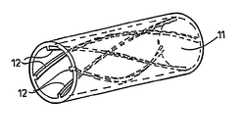
- FIG. 1is a perspective view of a short length of tubing of a first embodiment suitable for prosthetic implant in a cardio-vascular system;
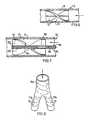
- FIG. 2is a cross-section of a second embodiment of tubing
- FIG. 3is a perspective view of a third embodiment
- FIG. 4is a view of the inside of a length of tubing, opened out;
- FIG. 5in an elevation of a mandrel for use in casting tubing according to the invention
- FIG. 6is a view of a vaned device in a tube
- FIG. 7is a view of a second vaned device in a tube
- FIG. 8is a view of a branched tube according to the invention.
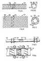
- FIG. 9is a view of a mesh material stent from the side, in its expanded condition
- FIG. 10is an end-on view of the stent of FIG. 9 ;
- FIG. 11is an opened-out view of the stent of FIG. 10 ;
- FIG. 12is an end-on view, to a larger scale, of the stent of FIG. 11 in its collapsed condition, before release from the catheter;
- FIG. 13is a view of a pipeline, with active helical-flow inducing means.
- FIG. 14is a section through the pipeline of FIG. 13 .
- the drawingsillustrate blood-flow tubing 11 having helical-flow inducing means 12 adapted to induce helical flow in such fashion as to eliminate or reduce turbulence.
- the tubingmay be artificial, for example woven or knitted synthetic polymer fibre, in which the helical-flow inducing means may be knitted or woven structure as by three dimensional knitted or woven formation, or extruded or cast tubing, or modified natural, e.g. autograft material with an insert or with grooving made e.g. by a laser.
- the helical-flow inducing means 12may comprise grooving 14 and/or ridging 15 , which may be multi-start grooving and/or ridging as seen in FIGS. 1, 2 and 4 .
- Square-section ridging, as seen in FIG. 1 , or grooving, or semi-circular section ridging and/or grooving, as seen in FIG. 2can be used, but other cross-sections will serve as well, for example, triangular.
- a non-circular section tube 11can have a twist, and may also have internal ridging and/or grooving.
- a twisted tubemay be cast as such on a twisted mandrel or, if, for example, of thermoplastic material, may be twisted and heat-set in that state.
- Even a circular-section tube, bent into a corkscrew shape,can, if the dimensions are appropriate for the density, velocity and viscosity of the liquid flowing through it, give rise to a circulation in the flow.
- the helical-flow inducing meansmay extend over the whole length of the tubing. It seems, on present knowledge, to be important at least to provide it where turbulence is likely to occur, for example at the inlet or outlet from the tubing, or in branched tubing as seen in FIG. 9 , where turbulence can be occasioned in the branch region and can be controlled by ridging and/or grooving 12 at the inlets to the two minor branches 11 b where they join the main branch 11 a , and/or in the main branch 11 a itself. It may be found desirable to have different ridging and/or grooving in the two minor branches, where, for example, they run at different angles to the main branch.
- the ridging and/or grooving 12has a reducing helix angle in the flow direction over at least part of its length—this is illustrated in FIG. 4 , where the grooving 12 is also tapered so as to extend only over an inlet region L, but the tapering and reducing angle could extend over longer lengths of tubing.
- the opposite—helix angle increasing and/or depth of grooving or height of ridging increasing in the flow directionmay also be appropriate in some circumstances.
- helix angleor range of helix angles, where increasing or decreasing angles are used, will depend on a number of factors, principally, the dimensions of the tubing, the density and viscosity of the liquid flowing through it, and the velocity of the liquid flow. Generally, it is supposed that angles between 5° and 50°, preferably about 16° will give best results, but angles outside this range may also be found to be useful in some circumstances.
- FIG. 5is an elevation of a mandrel 51 such as may be used in a coagulation casting process to make prosthesis of polyether urethane or other biocompatible polymer. Grooves 52 are provided on the mandrel 51 which then forms a tube with internal ridging.
- FIGS. 6 and 7illustrate helical vane devices 71 which can be inserted in tubing to cause helical flow.
- the effectcan be increased by a probe 81 as used in angiography.
- the vanes 82are on a sleeve 83 and sufficiently flexible to be compressed on a rigid support 84 by a sleeve 85 of the probe 81 being advanced relative to a core 86 , the core 86 engaging the support 84 while the sleeve 85 is advanced against the sleeve 83 , the sleeve 83 being held in the compressed state by a ratchet arrangement 89 between support 84 and sleeve 83 .
- Such a devicemay be adjusted during angiography while observing the rotational flow induced, thereby, e.g. by MRI.
- the adjustmentmay be effected in any other fashion, e.g. by the application of torque to one end while holding the other end fixed.
- FIGS. 9 to 12illustrate an expansible mesh material stent 101 which is inserted by catheterisation.
- Such stentsare sometimes made of a metal with a shape memory and are presented on a catheter in collapsed form, expanding on release from the catheter as they reach body temperature, others expand elastically as they are pushed from a captive surround.
- the stent 101In its expanded condition, as shown in FIGS. 9 and 10 , the stent 101 comprises a mesh cylinder formed, for example, of welded wires 102 with joined segments 103 extending helically around the periphery of the stent 101 , though some stents are of expanded metal sheet, in which case the segments would be integral strips.
- FIG. 11shows an opened-out version of the stent 101 , as if cut along a generator of the cylinder and laid flat, with the inside face uppermost.
- FIG. 12which is to a larger scale, shows the stent 101 in collapsed form around a catheter wire 105 , without, however, the associated surround which contains them for insertion and out from which they are pushed once maneouvered into position.
- blood flow tubingis found in various items of medical equipment such as heart-lung machines, dialysis machines and blood transfusion equipment.
- medical equipmentsuch as heart-lung machines, dialysis machines and blood transfusion equipment.
- blood flows much as it does in the bodyit could be at least as important to fashion such tubing to give the best possible flow characteristics, in particular, the avoidance of thromboses being generated during prolonged use of the equipment, as in heart surgery and dialysis, and the principles set out above in relation to natural and artificial grafts can also be applied to such external blood flow tubing.
- FIGS. 13 and 14illustrate, by way of example, the application of the notion of helical flow to an oil pipeline 141 .
- the pipeline 141is itself made up from pipe sections 142 , which may themselves have internal helical grooving and/or ridging 143 .
- active flow rotating means 144are provided at intervals along the pipeline 141 , at junctions between pipe sections 142 .
- the active flow rotating meanscomprise, as seen in FIG. 13 , rotary vanes 145 mounted in connecting rings 146 .
- vanesmay be desirable to drive the vanes by external means, such, for example, as a motor, which can be, for example, solar powered, or it may be preferred to derive power for rotating the vanes from the flow itself, the general idea being to refresh any swirl component that might have attenuated over the preceding pipe section.
- external meanssuch as a motor, which can be, for example, solar powered, or it may be preferred to derive power for rotating the vanes from the flow itself, the general idea being to refresh any swirl component that might have attenuated over the preceding pipe section.
Landscapes
- Health & Medical Sciences (AREA)
- Engineering & Computer Science (AREA)
- Biomedical Technology (AREA)
- Cardiology (AREA)
- Oral & Maxillofacial Surgery (AREA)
- Transplantation (AREA)
- Heart & Thoracic Surgery (AREA)
- Vascular Medicine (AREA)
- Life Sciences & Earth Sciences (AREA)
- Animal Behavior & Ethology (AREA)
- General Health & Medical Sciences (AREA)
- Public Health (AREA)
- Veterinary Medicine (AREA)
- Gastroenterology & Hepatology (AREA)
- Pulmonology (AREA)
- Prostheses (AREA)
- Materials For Medical Uses (AREA)
- External Artificial Organs (AREA)
- Magnetic Resonance Imaging Apparatus (AREA)
- Ultra Sonic Daignosis Equipment (AREA)
- Infusion, Injection, And Reservoir Apparatuses (AREA)
Abstract
Description
Claims (10)
Priority Applications (2)
| Application Number | Priority Date | Filing Date | Title |
|---|---|---|---|
| US13/345,628US9737421B2 (en) | 1998-12-28 | 2012-01-06 | Blood-flow tubing |
| US15/214,938US10188532B2 (en) | 1998-12-29 | 2016-07-20 | Blood-flow tubing |
Applications Claiming Priority (7)
| Application Number | Priority Date | Filing Date | Title |
|---|---|---|---|
| GB9828696.6 | 1998-12-28 | ||
| GBGB9828696.6AGB9828696D0 (en) | 1998-12-29 | 1998-12-29 | Blood-flow tubing |
| GBPCT/GB99/04449 | 1999-12-23 | ||
| PCT/GB1999/004449WO2000038591A2 (en) | 1998-12-29 | 1999-12-23 | Blood-flow tubing |
| WOPCT/GB99/04449 | 1999-12-23 | ||
| US11/696,052US8110267B2 (en) | 1998-12-29 | 2007-04-03 | Blood-flow tubing |
| US13/345,628US9737421B2 (en) | 1998-12-28 | 2012-01-06 | Blood-flow tubing |
Related Parent Applications (1)
| Application Number | Title | Priority Date | Filing Date |
|---|---|---|---|
| US11/696,052ContinuationUS8110267B2 (en) | 1998-12-28 | 2007-04-03 | Blood-flow tubing |
Related Child Applications (1)
| Application Number | Title | Priority Date | Filing Date |
|---|---|---|---|
| US15/214,938ContinuationUS10188532B2 (en) | 1998-12-29 | 2016-07-20 | Blood-flow tubing |
Publications (2)
| Publication Number | Publication Date |
|---|---|
| US20120123520A1 US20120123520A1 (en) | 2012-05-17 |
| US9737421B2true US9737421B2 (en) | 2017-08-22 |
Family
ID=10845072
Family Applications (4)
| Application Number | Title | Priority Date | Filing Date |
|---|---|---|---|
| US10/650,217Expired - Fee RelatedUS7682673B2 (en) | 1998-12-28 | 2003-08-19 | Blood-flow tubing |
| US11/696,052Expired - Fee RelatedUS8110267B2 (en) | 1998-12-28 | 2007-04-03 | Blood-flow tubing |
| US13/345,628Expired - Fee RelatedUS9737421B2 (en) | 1998-12-28 | 2012-01-06 | Blood-flow tubing |
| US15/214,938Expired - Fee RelatedUS10188532B2 (en) | 1998-12-29 | 2016-07-20 | Blood-flow tubing |
Family Applications Before (2)
| Application Number | Title | Priority Date | Filing Date |
|---|---|---|---|
| US10/650,217Expired - Fee RelatedUS7682673B2 (en) | 1998-12-28 | 2003-08-19 | Blood-flow tubing |
| US11/696,052Expired - Fee RelatedUS8110267B2 (en) | 1998-12-28 | 2007-04-03 | Blood-flow tubing |
Family Applications After (1)
| Application Number | Title | Priority Date | Filing Date |
|---|---|---|---|
| US15/214,938Expired - Fee RelatedUS10188532B2 (en) | 1998-12-29 | 2016-07-20 | Blood-flow tubing |
Country Status (9)
| Country | Link |
|---|---|
| US (4) | US7682673B2 (en) |
| EP (2) | EP1254645B1 (en) |
| JP (1) | JP4276790B2 (en) |
| AT (1) | ATE360405T1 (en) |
| AU (1) | AU3060700A (en) |
| DE (1) | DE69935932T2 (en) |
| ES (1) | ES2286178T3 (en) |
| GB (1) | GB9828696D0 (en) |
| WO (1) | WO2000038591A2 (en) |
Cited By (2)
| Publication number | Priority date | Publication date | Assignee | Title |
|---|---|---|---|---|
| US20160015934A1 (en)* | 2013-04-01 | 2016-01-21 | Terumo Kabushiki Kaisha | Sheath |
| US20190178729A1 (en)* | 2017-12-08 | 2019-06-13 | Hitachi Metals, Ltd. | Pressure-sensitive sensor and method for manufacturing the same |
Families Citing this family (186)
| Publication number | Priority date | Publication date | Assignee | Title |
|---|---|---|---|---|
| GB9828696D0 (en) | 1998-12-29 | 1999-02-17 | Houston J G | Blood-flow tubing |
| EP1127557A1 (en)* | 2000-02-25 | 2001-08-29 | EndoArt S.A. | Vascular graft |
| AU2001264750B2 (en)* | 2000-05-19 | 2006-08-31 | Vactronix Scientific, Llc | Methods and apparatus for manufacturing an intravascular stent |
| GB2371346B (en) | 2000-12-14 | 2002-12-04 | Tayside Flow Technologies Ltd | Improving fluid flow in tubing |
| GB2371230B (en)* | 2001-02-08 | 2002-10-16 | Tayside Flow Technologies Ltd | Pumps |
| GB2379996B (en) | 2001-06-05 | 2004-05-19 | Tayside Flow Technologies Ltd | Flow means |
| US20020188167A1 (en) | 2001-06-06 | 2002-12-12 | Anthony Viole | Multilumen catheter for minimizing limb ischemia |
| GB2373058B (en) | 2001-09-18 | 2003-02-19 | Tayside Flow Technologies Ltd | Spiral flow testing |
| GB2369797B (en)* | 2001-11-20 | 2002-11-06 | Tayside Flow Technologies Ltd | Helical formations in tubes |
| GB2384189A (en) | 2001-11-21 | 2003-07-23 | Tayside Flow Technologies Ltd | Helix shaped insert for flow moification in a duct or stent |
| AUPR982502A0 (en) | 2002-01-03 | 2002-01-31 | Pax Fluid Systems Inc. | A heat exchanger |
| EP1470338A4 (en)* | 2002-01-03 | 2012-01-11 | Pax Scient Inc | Vortex ring generator |
| AUPR982302A0 (en)* | 2002-01-03 | 2002-01-31 | Pax Fluid Systems Inc. | A fluid flow controller |
| GB0209454D0 (en)* | 2002-04-25 | 2002-06-05 | Univ Nottingham | Duct |
| US20030216804A1 (en)* | 2002-05-14 | 2003-11-20 | Debeer Nicholas C. | Shape memory polymer stent |
| EP1509169B1 (en) | 2002-06-05 | 2012-10-10 | Vascular Flow Technologies Limited | A method of determining the helix angle of a helical formation for a conduit |
| NO20024883D0 (en)* | 2002-10-09 | 2002-10-09 | Amersham Health As | Snake |
| GB0227369D0 (en)* | 2002-11-23 | 2002-12-31 | Tayside Flow Technologies Ltd | A helical formation for a conduit |
| US9333102B2 (en) | 2003-02-24 | 2016-05-10 | Allium Medical Solutions Ltd. | Stent |
| AU2004221655B2 (en)* | 2003-03-18 | 2010-07-15 | Imperial College Innovations Limited | Method for use in multiphase flow |
| GB0306176D0 (en) | 2003-03-18 | 2003-04-23 | Imp College Innovations Ltd | Tubing |
| BRPI0408418A (en) | 2003-03-18 | 2006-03-21 | Veryan Medical Ltd | stent |
| CA2519381A1 (en) | 2003-03-18 | 2004-09-30 | Veryan Medical Limited | Device for placement externally of a body fluid flow conduit |
| GB0306179D0 (en)* | 2003-03-18 | 2003-04-23 | Imp College Innovations Ltd | Piping |
| USD524442S1 (en) | 2003-05-29 | 2006-07-04 | Tayside Flow Technologies Limited | Vascular tube |
| USD567946S1 (en) | 2003-05-29 | 2008-04-29 | Tayside Flow Technologies Limited | Vascular tube |
| AU2003903386A0 (en) | 2003-07-02 | 2003-07-17 | Pax Scientific, Inc | Fluid flow control device |
| GB0315714D0 (en)* | 2003-07-04 | 2003-08-13 | Tayside Flow Technologies Ltd | An internal formation for a conduit |
| DE10333477A1 (en)* | 2003-07-22 | 2005-02-24 | Aloys Wobben | Flow passage for fluids has at least one wall bounding flow passage in such way that with through-flow of fluid at least one flow region is formed which has axial and simultaneously tangential flow component |
| US7416525B2 (en) | 2003-09-18 | 2008-08-26 | Myrakelle, Llc | Rotary blood pump |
| KR100977217B1 (en) | 2003-10-02 | 2010-08-23 | 엘지디스플레이 주식회사 | Driving apparatus and method of liquid crystal display device |
| CA2544516C (en)* | 2003-11-04 | 2014-04-29 | Pax Scientific, Inc. | Fluid circulation system |
| JP4695097B2 (en) | 2004-01-30 | 2011-06-08 | パックス サイエンティフィック インコーポレイテッド | Centrifugal fan, pump or turbine housing |
| CN1985093A (en) | 2004-01-30 | 2007-06-20 | 百思科技公司 | Housing for a centrifugal fan, pump or turbine |
| GB0402736D0 (en) | 2004-02-06 | 2004-03-10 | Tayside Flow Technologies Ltd | A drug delivery device |
| GB0406719D0 (en) | 2004-03-25 | 2004-04-28 | Tayside Flow Technologies Ltd | A tubular conduit |
| WO2005123158A1 (en)* | 2004-06-10 | 2005-12-29 | Orqis Medical Corporation | Cannulae and system having reduced flow resistance |
| US7445592B2 (en) | 2004-06-10 | 2008-11-04 | Orqis Medical Corporation | Cannulae having reduced flow resistance |
| JP4282567B2 (en)* | 2004-08-03 | 2009-06-24 | 嶌田 泰之 | Blood vessel and blood supply device using the same |
| EP2151257B1 (en) | 2004-08-13 | 2013-04-17 | Delgado, Reynolds M., III | Apparatus for long-term assisting a left ventricle to pump blood |
| JP4370230B2 (en)* | 2004-09-08 | 2009-11-25 | 株式会社カネカメディックス | Medical tubing and shunt system |
| US7393181B2 (en)* | 2004-09-17 | 2008-07-01 | The Penn State Research Foundation | Expandable impeller pump |
| US7749462B2 (en) | 2004-09-21 | 2010-07-06 | Technip France S.A.S. | Piping |
| GB0420971D0 (en) | 2004-09-21 | 2004-10-20 | Imp College Innovations Ltd | Piping |
| US8029749B2 (en) | 2004-09-21 | 2011-10-04 | Technip France S.A.S. | Cracking furnace |
| US8808354B2 (en) | 2004-09-22 | 2014-08-19 | Veryan Medical Limited | Helical stent |
| GB2418362C (en)* | 2004-09-22 | 2010-05-05 | Veryan Medical Ltd | Stent |
| US20060085065A1 (en)* | 2004-10-15 | 2006-04-20 | Krause Arthur A | Stent with auxiliary treatment structure |
| GB0423422D0 (en) | 2004-10-21 | 2004-11-24 | Bard Inc C R | Medical device for fluid flow, and method of forming such device |
| GB2425485A (en)* | 2005-04-29 | 2006-11-01 | Veryan Medical Ltd | Shape memory stent producing non planar, swirling flow |
| WO2006136861A1 (en)* | 2005-06-24 | 2006-12-28 | Veryan Medical Limited | Artificial graft tubing |
| JP5118042B2 (en) | 2005-09-06 | 2013-01-16 | シー・アール・バード・インコーポレーテッド | Implant for transplantation containing drug crystals |
| GB2429650A (en) | 2005-09-06 | 2007-03-07 | Tayside Flow Technologies Ltd | A tubular graft |
| CN102380135A (en) | 2006-03-23 | 2012-03-21 | 宾州研究基金会 | Heart assist device with expandable impeller pump |
| KR20090074110A (en) | 2006-03-31 | 2009-07-06 | 오퀴스 메디컬 코포레이션 | Rotary Blood Pump |
| USD570996S1 (en) | 2006-09-25 | 2008-06-10 | Pax Scientific, Inc. | Rotor |
| US8328522B2 (en) | 2006-09-29 | 2012-12-11 | Pax Scientific, Inc. | Axial flow fan |
| USD570999S1 (en) | 2006-11-22 | 2008-06-10 | Pax Scientific, Inc. | Rotor |
| DE102007008185A1 (en) | 2007-02-13 | 2008-08-14 | Aesculap Ag & Co. Kg | Nonwoven blood vessel prosthesis has a corrugated pleating, along the wall, for bending as required without loss of diameter |
| DE102007015462A1 (en)* | 2007-03-30 | 2008-10-02 | Acandis Gmbh & Co. Kg | Implant and method and apparatus for producing such an implant |
| US8376053B2 (en) | 2007-10-01 | 2013-02-19 | Premium Artificial Lift Systems Ltd. | Fluid flow conduit, method and use |
| WO2009123024A1 (en)* | 2008-03-31 | 2009-10-08 | テルモ株式会社 | Indwelling needle assembly |
| US8109909B2 (en)* | 2008-03-31 | 2012-02-07 | Terumo Kabushiki Kaisha | Medical instrument |
| CN101980745A (en)* | 2008-03-31 | 2011-02-23 | 泰尔茂株式会社 | Indwelling needle assembly |
| US20100256731A1 (en)* | 2009-04-02 | 2010-10-07 | Mangiardi Eric K | Stent |
| US8231686B2 (en)* | 2008-06-11 | 2012-07-31 | Eric Mangiardi | Stent |
| US10245165B2 (en)* | 2009-04-02 | 2019-04-02 | Q3 Medical Devices Limited | Stent |
| US20090308472A1 (en)* | 2008-06-15 | 2009-12-17 | Jayden David Harman | Swirl Inducer |
| GB0817219D0 (en) | 2008-09-19 | 2008-10-29 | Heliswirl Petrochemicals Ltd | Cracking furnace |
| US9700365B2 (en)* | 2008-10-06 | 2017-07-11 | Santa Anna Tech Llc | Method and apparatus for the ablation of gastrointestinal tissue |
| US10695126B2 (en) | 2008-10-06 | 2020-06-30 | Santa Anna Tech Llc | Catheter with a double balloon structure to generate and apply a heated ablative zone to tissue |
| US9561066B2 (en) | 2008-10-06 | 2017-02-07 | Virender K. Sharma | Method and apparatus for tissue ablation |
| US9561068B2 (en) | 2008-10-06 | 2017-02-07 | Virender K. Sharma | Method and apparatus for tissue ablation |
| US10064697B2 (en) | 2008-10-06 | 2018-09-04 | Santa Anna Tech Llc | Vapor based ablation system for treating various indications |
| US10603489B2 (en) | 2008-10-09 | 2020-03-31 | Virender K. Sharma | Methods and apparatuses for stimulating blood vessels in order to control, treat, and/or prevent a hemorrhage |
| US9079028B2 (en) | 2008-10-09 | 2015-07-14 | Virender K. Sharma | Method and apparatus for stimulating the vascular system |
| US9597214B2 (en) | 2008-10-10 | 2017-03-21 | Kevin Heraty | Medical device |
| GB0908614D0 (en)* | 2009-05-19 | 2009-06-24 | Tayside Flow Technologies Ltd | A vascular graft |
| US20100298924A1 (en)* | 2009-05-19 | 2010-11-25 | Tayside Flow Technologies Ltd. | Vascular Graft |
| CN102481398A (en) | 2009-07-01 | 2012-05-30 | 宾夕法尼亚州研究基金会 | Blood pump with expandable cannula |
| GB2475338A (en) | 2009-11-17 | 2011-05-18 | Tayside Flow Technologies Ltd | A tubular conduit with an internal and external helical formation |
| JP5578415B2 (en)* | 2010-04-21 | 2014-08-27 | 株式会社リコー | Cooling device and image forming apparatus |
| MY169594A (en)* | 2010-04-22 | 2019-04-22 | Biovic Sdn Bhd | Expanded ptfe medical devices with spiraled ridges and process of manufacture thereof |
| US9247942B2 (en) | 2010-06-29 | 2016-02-02 | Artventive Medical Group, Inc. | Reversible tubal contraceptive device |
| EP2588042A4 (en) | 2010-06-29 | 2015-03-18 | Artventive Medical Group Inc | Reducing flow through a tubular structure |
| US9149277B2 (en) | 2010-10-18 | 2015-10-06 | Artventive Medical Group, Inc. | Expandable device delivery |
| US9381712B2 (en)* | 2010-12-23 | 2016-07-05 | Guill Tool & Engineering Co., Inc. | Method and apparatus for forming high strength products |
| US8485961B2 (en) | 2011-01-05 | 2013-07-16 | Thoratec Corporation | Impeller housing for percutaneous heart pump |
| US8597170B2 (en) | 2011-01-05 | 2013-12-03 | Thoratec Corporation | Catheter pump |
| WO2012094535A2 (en) | 2011-01-06 | 2012-07-12 | Thoratec Corporation | Percutaneous heart pump |
| WO2012094641A2 (en) | 2011-01-06 | 2012-07-12 | Thoratec Corporation | Percutaneous heart pump |
| CN103889481B (en) | 2011-08-02 | 2016-03-09 | 美敦力公司 | Hemodialysis system with flow path with controlled compliance volume |
| US20130110221A1 (en)* | 2011-10-27 | 2013-05-02 | Triona Campbell | Stent with Inwardly-Directed Protrusion |
| US9782583B2 (en) | 2012-02-21 | 2017-10-10 | Virender K. Sharma | System and method for electrical stimulation of anorectal structures to treat urinary dysfunction |
| US10576278B2 (en) | 2012-02-21 | 2020-03-03 | Virender K. Sharma | System and method for electrical stimulation of anorectal structures to treat urinary dysfunction |
| US8706234B2 (en) | 2012-02-21 | 2014-04-22 | Virender K. Sharma | System and method for electrical stimulation of anorectal structures to treat anal dysfunction |
| US9446179B2 (en) | 2012-05-14 | 2016-09-20 | Thoratec Corporation | Distal bearing support |
| US9327067B2 (en) | 2012-05-14 | 2016-05-03 | Thoratec Corporation | Impeller for catheter pump |
| EP4218887A1 (en) | 2012-05-14 | 2023-08-02 | Tc1 Llc | Mechanical circulatory support device for stabilizing a patient after cardiogenic shock |
| US8721517B2 (en) | 2012-05-14 | 2014-05-13 | Thoratec Corporation | Impeller for catheter pump |
| US9872947B2 (en) | 2012-05-14 | 2018-01-23 | Tc1 Llc | Sheath system for catheter pump |
| CN102670337B (en)* | 2012-05-29 | 2015-03-04 | 朱晓义 | Siphunculus of human body and channel of human body |
| US9421311B2 (en) | 2012-07-03 | 2016-08-23 | Thoratec Corporation | Motor assembly for catheter pump |
| EP4186557A1 (en) | 2012-07-03 | 2023-05-31 | Tc1 Llc | Motor assembly for catheter pump |
| US9358329B2 (en) | 2012-07-03 | 2016-06-07 | Thoratec Corporation | Catheter pump |
| CA3113910C (en) | 2012-08-10 | 2023-09-19 | Abiomed, Inc. | Graft anchor devices, systems, and methods |
| AU2013317799B2 (en)* | 2012-09-21 | 2018-11-22 | Ng1 Technologies, Llc | Pipeline systems and methods |
| WO2014078506A2 (en)* | 2012-11-14 | 2014-05-22 | Ams Research Corporation | Cell delivery device and system with anti-clumping feature and methods for pelvic tissue treatment |
| US11154648B2 (en) | 2013-01-09 | 2021-10-26 | Medtronic, Inc. | Fluid circuits for sorbent cartridge with sensors |
| US9713666B2 (en) | 2013-01-09 | 2017-07-25 | Medtronic, Inc. | Recirculating dialysate fluid circuit for blood measurement |
| EP3964151A3 (en) | 2013-01-17 | 2022-03-30 | Virender K. Sharma | Apparatus for tissue ablation |
| US10850016B2 (en) | 2013-02-01 | 2020-12-01 | Medtronic, Inc. | Modular fluid therapy system having jumpered flow paths and systems and methods for cleaning and disinfection |
| US10010663B2 (en) | 2013-02-01 | 2018-07-03 | Medtronic, Inc. | Fluid circuit for delivery of renal replacement therapies |
| US9623164B2 (en) | 2013-02-01 | 2017-04-18 | Medtronic, Inc. | Systems and methods for multifunctional volumetric fluid control |
| US8984733B2 (en) | 2013-02-05 | 2015-03-24 | Artventive Medical Group, Inc. | Bodily lumen occlusion |
| US9095344B2 (en) | 2013-02-05 | 2015-08-04 | Artventive Medical Group, Inc. | Methods and apparatuses for blood vessel occlusion |
| US11077294B2 (en) | 2013-03-13 | 2021-08-03 | Tc1 Llc | Sheath assembly for catheter pump |
| US11033728B2 (en) | 2013-03-13 | 2021-06-15 | Tc1 Llc | Fluid handling system |
| WO2014164136A1 (en) | 2013-03-13 | 2014-10-09 | Thoratec Corporation | Fluid handling system |
| US9308302B2 (en) | 2013-03-15 | 2016-04-12 | Thoratec Corporation | Catheter pump assembly including a stator |
| EP4190376A1 (en) | 2013-03-15 | 2023-06-07 | Tc1 Llc | Catheter pump assembly including a stator |
| WO2014178198A1 (en)* | 2013-05-02 | 2014-11-06 | テルモ株式会社 | Blood clot removal device |
| GB2514135B (en)* | 2013-05-14 | 2015-04-15 | Cook Medical Technologies Llc | Implantable flow diverter |
| US20160102797A1 (en)* | 2013-05-24 | 2016-04-14 | Nigel Richard Farrow | Improvement to material flow |
| US9636116B2 (en) | 2013-06-14 | 2017-05-02 | Artventive Medical Group, Inc. | Implantable luminal devices |
| US10149968B2 (en) | 2013-06-14 | 2018-12-11 | Artventive Medical Group, Inc. | Catheter-assisted tumor treatment |
| US9737306B2 (en) | 2013-06-14 | 2017-08-22 | Artventive Medical Group, Inc. | Implantable luminal devices |
| US9737308B2 (en) | 2013-06-14 | 2017-08-22 | Artventive Medical Group, Inc. | Catheter-assisted tumor treatment |
| EP2848232A1 (en)* | 2013-09-17 | 2015-03-18 | Cortronik GmbH | Stent with flow directing elements |
| BR112016006071B1 (en) | 2013-09-19 | 2021-12-28 | Universitãtsspital Basel | ARTIFICIAL VASCULAR GRAFT AND METHOD FOR PRODUCTION OF AN ARTIFICIAL VASCULAR GRAFT |
| WO2015041547A1 (en)* | 2013-09-23 | 2015-03-26 | Fisher & Paykel Healthcare Limited | Nasal cannula with turbulation elements |
| US10537875B2 (en) | 2013-11-26 | 2020-01-21 | Medtronic, Inc. | Precision recharging of sorbent materials using patient and session data |
| US9884145B2 (en) | 2013-11-26 | 2018-02-06 | Medtronic, Inc. | Parallel modules for in-line recharging of sorbents using alternate duty cycles |
| EP3131597B1 (en) | 2014-04-15 | 2020-12-02 | Tc1 Llc | Catheter pump introducer systems |
| WO2015160943A1 (en) | 2014-04-15 | 2015-10-22 | Thoratec Corporation | Sensors for catheter pumps |
| EP3131599B1 (en) | 2014-04-15 | 2019-02-20 | Tc1 Llc | Catheter pump with access ports |
| US10583232B2 (en) | 2014-04-15 | 2020-03-10 | Tc1 Llc | Catheter pump with off-set motor position |
| US10363043B2 (en) | 2014-05-01 | 2019-07-30 | Artventive Medical Group, Inc. | Treatment of incompetent vessels |
| US9561320B2 (en) | 2014-06-05 | 2017-02-07 | Cook Medical Technologies Llc | Device for promoting fistula patency and method |
| EP2952142B1 (en)* | 2014-06-06 | 2017-09-06 | Cook Medical Technologies LLC | Device for forming fistula between blood vessels |
| WO2015199768A1 (en) | 2014-06-24 | 2015-12-30 | Medtronic, Inc. | Stacked sorbent assembly |
| ES2989503T3 (en) | 2014-06-24 | 2024-11-26 | Mozarc Medical Us Llc | Modular dialysate regeneration assembly |
| EP3583973A1 (en) | 2014-08-18 | 2019-12-25 | Tc1 Llc | Guide features for percutaneous catheter pump |
| WO2016064931A1 (en) | 2014-10-20 | 2016-04-28 | Somarakis, Inc. | Helix amplifier pipe fittings |
| US11015850B2 (en)* | 2014-10-23 | 2021-05-25 | Mitsubishi Electric Corporation | Oil separator |
| US9675738B2 (en) | 2015-01-22 | 2017-06-13 | Tc1 Llc | Attachment mechanisms for motor of catheter pump |
| US9770543B2 (en) | 2015-01-22 | 2017-09-26 | Tc1 Llc | Reduced rotational mass motor assembly for catheter pump |
| WO2016118781A2 (en) | 2015-01-22 | 2016-07-28 | Thoratec Corporation | Motor assembly with heat exchanger for catheter pump |
| US9907890B2 (en) | 2015-04-16 | 2018-03-06 | Tc1 Llc | Catheter pump with positioning brace |
| DE102015005002A1 (en)* | 2015-04-21 | 2016-10-27 | Xenios Ag | cannula |
| GB201507919D0 (en)* | 2015-05-08 | 2015-06-24 | Vascular Flow Technologies Ltd | A conduit arrangement |
| GB201508593D0 (en)* | 2015-05-19 | 2015-07-01 | Vascular Flow Technologies Ltd | A stent |
| US10022252B2 (en)* | 2015-06-10 | 2018-07-17 | Cook Medical Technologies Llc | Spiral blood flow device with diameter independent helix angle |
| US10849627B2 (en)* | 2015-08-28 | 2020-12-01 | University Of Cincinnati | Arteriovenous fistula implant effective for inducing laminar blood flow |
| GB201516683D0 (en)* | 2015-09-21 | 2015-11-04 | Univ Bolton | Vascular graft |
| EP4290081A3 (en) | 2015-09-25 | 2024-02-21 | Procyrion, Inc. | Non-occluding intravascular blood pump providing reduced hemolysis |
| US10321984B2 (en) | 2016-02-19 | 2019-06-18 | Cook Medical Technologies Llc | Spiral flow inducing stent and canula cut method of making same |
| US10813644B2 (en) | 2016-04-01 | 2020-10-27 | Artventive Medical Group, Inc. | Occlusive implant and delivery system |
| US12364537B2 (en) | 2016-05-02 | 2025-07-22 | Santa Anna Tech Llc | Catheter with a double balloon structure to generate and apply a heated ablative zone to tissue |
| US11331140B2 (en) | 2016-05-19 | 2022-05-17 | Aqua Heart, Inc. | Heated vapor ablation systems and methods for treating cardiac conditions |
| US11160970B2 (en) | 2016-07-21 | 2021-11-02 | Tc1 Llc | Fluid seals for catheter pump motor assembly |
| EP3808401A1 (en) | 2016-07-21 | 2021-04-21 | Tc1 Llc | Gas-filled chamber for catheter pump motor assembly |
| US10981148B2 (en) | 2016-11-29 | 2021-04-20 | Medtronic, Inc. | Zirconium oxide module conditioning |
| CN114887153A (en)* | 2016-12-21 | 2022-08-12 | 亚克安娜治疗学有限公司 | Drug delivery systems and methods |
| US10960381B2 (en) | 2017-06-15 | 2021-03-30 | Medtronic, Inc. | Zirconium phosphate disinfection recharging and conditioning |
| WO2019033020A1 (en)* | 2017-08-11 | 2019-02-14 | Xinova, LLC | Cyclonic flow through a pulse electric field |
| US10517713B2 (en) | 2018-01-10 | 2019-12-31 | Cook Medical Technologies Llc | Vascular graft with helical flow compliance compartments |
| US10893929B2 (en) | 2018-01-10 | 2021-01-19 | Cook Medical Technologies Llc | Vascular graft with compartments for compliance matching |
| US20190328559A1 (en)* | 2018-04-25 | 2019-10-31 | High Desert Radiology, P.C. | Methods and apparatus for enhanced flow stent device |
| WO2019213378A1 (en)* | 2018-05-02 | 2019-11-07 | Rensselaer Polytechnic Institute | Systems for mechanically preventing restenosis in peripheral vascular stents |
| EP3801324B1 (en) | 2018-06-01 | 2025-05-28 | Aqua Medical, Inc. | Vapor generation and delivery systems |
| US12285552B2 (en) | 2018-08-14 | 2025-04-29 | Mozarc Medical Us Llc | Precision dialysis therapy based on sorbent effluent analysis |
| US11213616B2 (en) | 2018-08-24 | 2022-01-04 | Medtronic, Inc. | Recharge solution for zirconium phosphate |
| CN110251272A (en)* | 2019-06-13 | 2019-09-20 | 杜伟远 | A kind of skeleton three-dimensional cardiovascular inner supporting device of attaching |
| JP7368190B2 (en)* | 2019-11-11 | 2023-10-24 | 信越ポリマー株式会社 | Method for manufacturing flexible medical tube |
| IL293625A (en) | 2019-12-03 | 2022-08-01 | Procyrion Inc | blood pumps |
| WO2021119413A1 (en) | 2019-12-13 | 2021-06-17 | Procyrion, Inc. | Support structures for intravascular blood pumps |
| GB2598271B (en)* | 2020-02-18 | 2024-03-06 | Wai Yin Lau Ernest | A scaffold for a tube |
| US11796110B2 (en)* | 2020-04-01 | 2023-10-24 | Intellihot, Inc. | Multi-purpose fitting |
| US10844887B1 (en)* | 2020-05-19 | 2020-11-24 | Vortex Pipe Systems LLC | Fluid flow enhancing device and culvert comprising same |
| CN112842459B (en)* | 2020-12-30 | 2022-11-01 | 武汉佑康科技有限公司 | Clear stone pipe structure |
| US12397093B2 (en) | 2021-05-18 | 2025-08-26 | Mozarc Medical Us Llc | Sorbent cartridge designs |
| CN113586830B (en)* | 2021-08-05 | 2023-11-24 | 中海油安全技术服务有限公司 | Three-way joint with flow guiding structure |
| WO2023086763A1 (en)* | 2021-11-09 | 2023-05-19 | Atrium Medical Corporation | Vascular graft with pulsation damping |
| US11378110B1 (en)* | 2022-01-05 | 2022-07-05 | Vortex Pipe Systems LLC | Flexible fluid flow modifying device |
| WO2024153478A1 (en)* | 2023-01-17 | 2024-07-25 | Koninklijke Philips N.V. | Flow modifying implant for venous or peripheral arterial disease |
Citations (34)
| Publication number | Priority date | Publication date | Assignee | Title |
|---|---|---|---|---|
| US3750444A (en)* | 1970-10-29 | 1973-08-07 | Kabel Metallwerke Ghh | Method of continuous production of tubing with helical or annular ribs |
| GB2092894A (en) | 1981-02-13 | 1982-08-25 | Thoratec Lab Corp | Arterial graft prosthesis |
| WO1983003349A1 (en) | 1982-03-25 | 1983-10-13 | Hood, Robert, Gordon | Vascular prosthesis |
| US4514997A (en)* | 1983-05-16 | 1985-05-07 | Packless Metal Hose, Inc. | Tube corrugating die |
| US4596548A (en) | 1985-03-25 | 1986-06-24 | Dlp Inc. | Single stage venous catheter |
| US4629458A (en) | 1985-02-26 | 1986-12-16 | Cordis Corporation | Reinforcing structure for cardiovascular graft |
| US4658892A (en) | 1983-12-28 | 1987-04-21 | Hitachi Cable, Ltd. | Heat-transfer tubes with grooved inner surface |
| US4743480A (en) | 1986-11-13 | 1988-05-10 | W. L. Gore & Associates, Inc. | Apparatus and method for extruding and expanding polytetrafluoroethylene tubing and the products produced thereby |
| US4753221A (en) | 1986-10-22 | 1988-06-28 | Intravascular Surgical Instruments, Inc. | Blood pumping catheter and method of use |
| US4892539A (en) | 1988-02-08 | 1990-01-09 | D-R Medical Systems, Inc. | Vascular graft |
| FR2657945A3 (en)* | 1990-02-07 | 1991-08-09 | Lee Jong Ho | Multi-layer hose including fluid-guiding helical projections on its internal surface |
| US5116350A (en) | 1987-03-17 | 1992-05-26 | Cordis Corporation | Catheter system having distal tip for opening obstructions |
| US5156620A (en)* | 1991-02-04 | 1992-10-20 | Pigott John P | Intraluminal graft/stent and balloon catheter for insertion thereof |
| WO1993015661A1 (en) | 1992-02-06 | 1993-08-19 | Interface Biomedical Laboratories Corp. | Anti-turbulent, anti-thrombogenic intravascular stent |
| EP0612536A1 (en) | 1993-02-24 | 1994-08-31 | Minnesota Mining And Manufacturing Company | Low velocity aortic cannula |
| WO1995020986A1 (en) | 1994-02-02 | 1995-08-10 | The Johns-Hopkins University | Winged biliary stent |
| WO1995035072A2 (en) | 1994-06-17 | 1995-12-28 | W.L. Gore & Associates, Inc. | Protective surgical sheath for coronary artery bypass grafts |
| EP0699423A2 (en) | 1994-08-02 | 1996-03-06 | Meadox Medicals, Inc. | Thinly woven flexible graft |
| US5579758A (en) | 1994-07-13 | 1996-12-03 | Century; Theodore J. | Sub-miniature aerosolizer with helical flow path formed by threaded insert |
| US5609624A (en) | 1993-10-08 | 1997-03-11 | Impra, Inc. | Reinforced vascular graft and method of making same |
| US5653745A (en)* | 1991-02-28 | 1997-08-05 | Medtronic, Inc. | Prosthetic vascular graft with a pleated structure |
| WO1998026731A2 (en) | 1996-12-03 | 1998-06-25 | Atrium Medical Corporation | Multi-stage prosthesis |
| US5824212A (en) | 1995-12-06 | 1998-10-20 | Kevin Business Corporation | Cyclone apparatus for removal of air from air containing blood |
| WO1998053764A2 (en) | 1997-05-27 | 1998-12-03 | Imperial College Of Science Technology & Medicine | Stents for blood vessels |
| US5989230A (en) | 1996-01-11 | 1999-11-23 | Essex Technology, Inc. | Rotate to advance catheterization system |
| US6261312B1 (en)* | 1998-06-23 | 2001-07-17 | Innercool Therapies, Inc. | Inflatable catheter for selective organ heating and cooling and method of using the same |
| WO2001062185A1 (en) | 2000-02-25 | 2001-08-30 | Endoart S.A. | Vascular device |
| WO2001089419A1 (en) | 2000-05-19 | 2001-11-29 | C.R. Bard, Inc. | Stents and stenting methods |
| US6500186B2 (en) | 2001-04-17 | 2002-12-31 | Scimed Life Systems, Inc. | In-stent ablative tool |
| US6514284B1 (en)* | 2000-04-20 | 2003-02-04 | Advanced Cardiovascular Systems, Inc. | Stent having inner flow channels |
| US20030225453A1 (en) | 1999-03-03 | 2003-12-04 | Trivascular, Inc. | Inflatable intraluminal graft |
| US7114524B2 (en) | 2000-12-14 | 2006-10-03 | Tayside Flow Technologies Limited | Fluid flow in tubing |
| US20060265051A1 (en)* | 2003-03-18 | 2006-11-23 | Veryan Medical Limited | Helical stent |
| US7185677B2 (en) | 2001-11-21 | 2007-03-06 | Tayside Flow Technologies Limited | Helical formation for a conduit |
Family Cites Families (32)
| Publication number | Priority date | Publication date | Assignee | Title |
|---|---|---|---|---|
| US653745A (en)* | 1899-08-17 | 1900-07-17 | William M Jewell | Method of making reagents for purifying water. |
| US1974110A (en) | 1932-12-21 | 1934-09-18 | Frank R Higley | Curved conduit |
| GB409528A (en) | 1933-06-28 | 1934-05-03 | Aerol Engine Corp | Improvements in liquid conducting conduits |
| GB729618A (en) | 1952-05-05 | 1955-05-11 | Mannesmann Ag | Improvements in or relating to swirl tubes |
| US3479670A (en) | 1966-10-19 | 1969-11-25 | Ethicon Inc | Tubular prosthetic implant having helical thermoplastic wrapping therearound |
| US3457762A (en) | 1967-04-28 | 1969-07-29 | Arma Corp | Compression method for making a tubular product |
| US3606780A (en) | 1967-11-28 | 1971-09-21 | Kichisaburo Nagahara | Method for manufacturing helical pipe for heat exchangers |
| US3503246A (en) | 1967-12-28 | 1970-03-31 | Hiroyasu Shiokawa | Method of manufacturing a spiral metal tube |
| US3693329A (en) | 1970-08-24 | 1972-09-26 | Porta Test Mfg | Hub assembly for in-line centrifugal separator |
| US3746126A (en) | 1971-07-09 | 1973-07-17 | Cardenas I De | Sound-muffling device |
| GB2093943B (en) | 1981-03-03 | 1984-05-23 | Redland Pipes Ltd | Renovation of tunnels |
| USD290752S (en) | 1984-07-25 | 1987-07-07 | Daiwa Seiko, Inc. | Synthetic resin tube |
| AU95818S (en) | 1985-09-13 | 1987-03-26 | Oy Uponor A B | Lighweight tube |
| FI88111C (en) | 1989-04-26 | 1993-04-13 | Biocon Oy | Self-reinforcing surgical materials and agents |
| USD326031S (en) | 1989-05-09 | 1992-05-12 | American General Products, Inc. | Adjustable gas tube |
| FR2665119A1 (en) | 1990-07-30 | 1992-01-31 | Cebal | Method of obtaining recessed marks or outlines on a plastic or metal-plastic tubular sheet or part and its use in the manufacture of a flexible tube |
| USD327879S (en) | 1990-08-23 | 1992-07-14 | Aten International Co., Ltd. | Multi-port interface device for data processing equipment |
| USD338193S (en) | 1991-02-22 | 1993-08-10 | Seiko Epson Corporation | Data loop transceiver for coupling data between computer peripherals |
| US5500013A (en) | 1991-10-04 | 1996-03-19 | Scimed Life Systems, Inc. | Biodegradable drug delivery vascular stent |
| US5556426A (en) | 1994-08-02 | 1996-09-17 | Meadox Medicals, Inc. | PTFE implantable tubular prostheses with external coil support |
| USD376011S (en) | 1994-10-27 | 1996-11-26 | Mioko Nunokawa | Synthetic vascular prosthesis |
| US5865723A (en) | 1995-12-29 | 1999-02-02 | Ramus Medical Technologies | Method and apparatus for forming vascular prostheses |
| WO1998019632A1 (en) | 1996-11-07 | 1998-05-14 | Vascular Science Inc. | Artificial tubular body organ grafts |
| ZA9710342B (en)* | 1996-11-25 | 1998-06-10 | Alza Corp | Directional drug delivery stent and method of use. |
| US6494907B1 (en) | 1998-04-28 | 2002-12-17 | Intratherapeutics, Inc. | Braided stent |
| US6358276B1 (en)* | 1998-09-30 | 2002-03-19 | Impra, Inc. | Fluid containing endoluminal stent |
| GB2344053A (en) | 1998-11-30 | 2000-05-31 | Imperial College | Stents for blood vessels |
| GB9828696D0 (en) | 1998-12-29 | 1999-02-17 | Houston J G | Blood-flow tubing |
| US6248122B1 (en) | 1999-02-26 | 2001-06-19 | Vascular Architects, Inc. | Catheter with controlled release endoluminal prosthesis |
| GB2379996B (en) | 2001-06-05 | 2004-05-19 | Tayside Flow Technologies Ltd | Flow means |
| GB0227369D0 (en) | 2002-11-23 | 2002-12-31 | Tayside Flow Technologies Ltd | A helical formation for a conduit |
| GB0320243D0 (en) | 2003-08-29 | 2003-10-01 | Isis Innovation | Body armour |
- 1998
- 1998-12-29GBGBGB9828696.6Apatent/GB9828696D0/ennot_activeCeased
- 1999
- 1999-12-23DEDE69935932Tpatent/DE69935932T2/ennot_activeExpired - Lifetime
- 1999-12-23AUAU30607/00Apatent/AU3060700A/ennot_activeAbandoned
- 1999-12-23ATAT02013909Tpatent/ATE360405T1/ennot_activeIP Right Cessation
- 1999-12-23WOPCT/GB1999/004449patent/WO2000038591A2/enactiveApplication Filing
- 1999-12-23EPEP02013909Apatent/EP1254645B1/ennot_activeExpired - Lifetime
- 1999-12-23EPEP99964755Apatent/EP1139917A2/ennot_activeCeased
- 1999-12-23ESES02013909Tpatent/ES2286178T3/ennot_activeExpired - Lifetime
- 1999-12-23JPJP2000590546Apatent/JP4276790B2/ennot_activeExpired - Lifetime
- 2003
- 2003-08-19USUS10/650,217patent/US7682673B2/ennot_activeExpired - Fee Related
- 2007
- 2007-04-03USUS11/696,052patent/US8110267B2/ennot_activeExpired - Fee Related
- 2012
- 2012-01-06USUS13/345,628patent/US9737421B2/ennot_activeExpired - Fee Related
- 2016
- 2016-07-20USUS15/214,938patent/US10188532B2/ennot_activeExpired - Fee Related
Patent Citations (37)
| Publication number | Priority date | Publication date | Assignee | Title |
|---|---|---|---|---|
| US3750444A (en)* | 1970-10-29 | 1973-08-07 | Kabel Metallwerke Ghh | Method of continuous production of tubing with helical or annular ribs |
| GB2092894A (en) | 1981-02-13 | 1982-08-25 | Thoratec Lab Corp | Arterial graft prosthesis |
| WO1983003349A1 (en) | 1982-03-25 | 1983-10-13 | Hood, Robert, Gordon | Vascular prosthesis |
| US4514997A (en)* | 1983-05-16 | 1985-05-07 | Packless Metal Hose, Inc. | Tube corrugating die |
| US4658892A (en) | 1983-12-28 | 1987-04-21 | Hitachi Cable, Ltd. | Heat-transfer tubes with grooved inner surface |
| US4658892B1 (en) | 1983-12-28 | 1990-04-17 | Hitachi Cable | |
| US4629458A (en) | 1985-02-26 | 1986-12-16 | Cordis Corporation | Reinforcing structure for cardiovascular graft |
| US4596548A (en) | 1985-03-25 | 1986-06-24 | Dlp Inc. | Single stage venous catheter |
| US4753221A (en) | 1986-10-22 | 1988-06-28 | Intravascular Surgical Instruments, Inc. | Blood pumping catheter and method of use |
| US4743480A (en) | 1986-11-13 | 1988-05-10 | W. L. Gore & Associates, Inc. | Apparatus and method for extruding and expanding polytetrafluoroethylene tubing and the products produced thereby |
| US5116350A (en) | 1987-03-17 | 1992-05-26 | Cordis Corporation | Catheter system having distal tip for opening obstructions |
| US5116350B1 (en) | 1987-03-17 | 1997-06-17 | Cordis Corp | Catheter system having distal tip for opening obstructions |
| US4892539A (en) | 1988-02-08 | 1990-01-09 | D-R Medical Systems, Inc. | Vascular graft |
| FR2657945A3 (en)* | 1990-02-07 | 1991-08-09 | Lee Jong Ho | Multi-layer hose including fluid-guiding helical projections on its internal surface |
| US5156620A (en)* | 1991-02-04 | 1992-10-20 | Pigott John P | Intraluminal graft/stent and balloon catheter for insertion thereof |
| US5653745A (en)* | 1991-02-28 | 1997-08-05 | Medtronic, Inc. | Prosthetic vascular graft with a pleated structure |
| WO1993015661A1 (en) | 1992-02-06 | 1993-08-19 | Interface Biomedical Laboratories Corp. | Anti-turbulent, anti-thrombogenic intravascular stent |
| EP0612536A1 (en) | 1993-02-24 | 1994-08-31 | Minnesota Mining And Manufacturing Company | Low velocity aortic cannula |
| US5609624A (en) | 1993-10-08 | 1997-03-11 | Impra, Inc. | Reinforced vascular graft and method of making same |
| WO1995020986A1 (en) | 1994-02-02 | 1995-08-10 | The Johns-Hopkins University | Winged biliary stent |
| WO1995035072A2 (en) | 1994-06-17 | 1995-12-28 | W.L. Gore & Associates, Inc. | Protective surgical sheath for coronary artery bypass grafts |
| US5579758A (en) | 1994-07-13 | 1996-12-03 | Century; Theodore J. | Sub-miniature aerosolizer with helical flow path formed by threaded insert |
| EP0699423A2 (en) | 1994-08-02 | 1996-03-06 | Meadox Medicals, Inc. | Thinly woven flexible graft |
| US5824212A (en) | 1995-12-06 | 1998-10-20 | Kevin Business Corporation | Cyclone apparatus for removal of air from air containing blood |
| US5989230A (en) | 1996-01-11 | 1999-11-23 | Essex Technology, Inc. | Rotate to advance catheterization system |
| WO1998026731A2 (en) | 1996-12-03 | 1998-06-25 | Atrium Medical Corporation | Multi-stage prosthesis |
| WO1998053764A2 (en) | 1997-05-27 | 1998-12-03 | Imperial College Of Science Technology & Medicine | Stents for blood vessels |
| US6261312B1 (en)* | 1998-06-23 | 2001-07-17 | Innercool Therapies, Inc. | Inflatable catheter for selective organ heating and cooling and method of using the same |
| US20030225453A1 (en) | 1999-03-03 | 2003-12-04 | Trivascular, Inc. | Inflatable intraluminal graft |
| WO2001062185A1 (en) | 2000-02-25 | 2001-08-30 | Endoart S.A. | Vascular device |
| US6514284B1 (en)* | 2000-04-20 | 2003-02-04 | Advanced Cardiovascular Systems, Inc. | Stent having inner flow channels |
| WO2001089419A1 (en) | 2000-05-19 | 2001-11-29 | C.R. Bard, Inc. | Stents and stenting methods |
| US7114524B2 (en) | 2000-12-14 | 2006-10-03 | Tayside Flow Technologies Limited | Fluid flow in tubing |
| US6500186B2 (en) | 2001-04-17 | 2002-12-31 | Scimed Life Systems, Inc. | In-stent ablative tool |
| US7185677B2 (en) | 2001-11-21 | 2007-03-06 | Tayside Flow Technologies Limited | Helical formation for a conduit |
| US7331989B2 (en) | 2001-11-21 | 2008-02-19 | Tayside Flow Technologies Limited | Insert for a conduit |
| US20060265051A1 (en)* | 2003-03-18 | 2006-11-23 | Veryan Medical Limited | Helical stent |
Non-Patent Citations (2)
| Title |
|---|
| P.A. Stonebridge, and C.M. Brophy, Spiral Laminar Flow in Arteries, The Lancet, Nov. 30, 1991, pp. 1360-1361, vol. 338, United Kingdom. |
| P.A. Stonebridge, P.R. Hoskins, P.L. Allan, and F.F.Belch, Spiral Laminar Flow In Vivo, Critical Science, Mar. 19, 1996, pp. 17-21, vol. 91, Great Britain. |
Cited By (3)
| Publication number | Priority date | Publication date | Assignee | Title |
|---|---|---|---|---|
| US20160015934A1 (en)* | 2013-04-01 | 2016-01-21 | Terumo Kabushiki Kaisha | Sheath |
| US20190178729A1 (en)* | 2017-12-08 | 2019-06-13 | Hitachi Metals, Ltd. | Pressure-sensitive sensor and method for manufacturing the same |
| US10890495B2 (en)* | 2017-12-08 | 2021-01-12 | Hitachi Metals, Ltd. | Pressure-sensitive sensor including a hollow tubular member of an elastic insulation |
Also Published As
| Publication number | Publication date |
|---|---|
| US20160346101A1 (en) | 2016-12-01 |
| US20070282417A1 (en) | 2007-12-06 |
| DE69935932D1 (en) | 2007-06-06 |
| JP4276790B2 (en) | 2009-06-10 |
| ES2286178T3 (en) | 2007-12-01 |
| US20120123520A1 (en) | 2012-05-17 |
| ATE360405T1 (en) | 2007-05-15 |
| GB9828696D0 (en) | 1999-02-17 |
| US10188532B2 (en) | 2019-01-29 |
| US20040037986A1 (en) | 2004-02-26 |
| JP2002533157A (en) | 2002-10-08 |
| AU3060700A (en) | 2000-07-31 |
| EP1254645A1 (en) | 2002-11-06 |
| WO2000038591A2 (en) | 2000-07-06 |
| EP1254645B1 (en) | 2007-04-25 |
| EP1139917A2 (en) | 2001-10-10 |
| DE69935932T2 (en) | 2008-01-10 |
| US7682673B2 (en) | 2010-03-23 |
| WO2000038591A3 (en) | 2000-10-26 |
| US8110267B2 (en) | 2012-02-07 |
Similar Documents
| Publication | Publication Date | Title |
|---|---|---|
| US9737421B2 (en) | Blood-flow tubing | |
| RU2257180C2 (en) | Expandable intravascular stent | |
| US9949852B2 (en) | Implant for supporting bodily conduits such as blood vessels or/and grafted vessels | |
| US6488705B2 (en) | Radially self-expanding implantable intraluminal device | |
| EP1127557A1 (en) | Vascular graft | |
| US20130274648A1 (en) | Blood flow controllers and methods | |
| KR20070083742A (en) | Stent | |
| EP1314406A2 (en) | An insert for a conduit | |
| US20090234431A1 (en) | Arteriovenous graft blood flow controllers and methods | |
| ZA200507491B (en) | Device for placement externally of a body fluid flow conduit | |
| CN111329620B (en) | Arterial stent blood vessel unit | |
| CN109966015A (en) | stent graft | |
| EP1603490B1 (en) | Device for placement externally of a body fluid flow conduit | |
| JP2006520632A5 (en) | ||
| JP2012527277A (en) | Vascular graft | |
| RU174103U1 (en) | VASCULAR FRAME |
Legal Events
| Date | Code | Title | Description |
|---|---|---|---|
| AS | Assignment | Owner name:TAYSIDE FLOW TECHNOLOGIES LIMITED, UNITED KINGDOM Free format text:ASSIGNMENT OF ASSIGNORS INTEREST;ASSIGNOR:TAYSIDE HEALTH BOARD;REEL/FRAME:042976/0948 Effective date:20060222 Owner name:VASCULAR FLOW TECHNOLOGIES LIMITED, UNITED KINGDOM Free format text:CHANGE OF NAME;ASSIGNOR:TAYSIDE FLOW TECHNOLOGIES LIMITED;REEL/FRAME:042977/0125 Effective date:20120201 Owner name:TAYSIDE HEALTH BOARD, UNITED KINGDOM Free format text:MERGER;ASSIGNOR:TAYSIDE UNIVERSITY HOSPITALS NHS TRUST;REEL/FRAME:042976/0361 Effective date:20040325 Owner name:TAYSIDE UNIVERSITY HOSPITALS NHS TRUST, SCOTLAND Free format text:ASSIGNMENT OF ASSIGNORS INTEREST;ASSIGNORS:HOUSTON, JOHN GRAEME;DICK, JOHN BRUCE CAMERON;STONEBRIDGE, PETER;REEL/FRAME:042975/0730 Effective date:20010618 | |
| STCF | Information on status: patent grant | Free format text:PATENTED CASE | |
| AS | Assignment | Owner name:VASCULAR FLOW TECHNOLOGIES LIMITED, UNITED KINGDOM Free format text:CORRECTIVE ASSIGNMENT TO CORRECT THE ASSIGNEE'S STREET ADDRESS PREVIOUSLY RECORDED AT REEL: 042977 FRAME: 0125. ASSIGNOR(S) HEREBY CONFIRMS THE CHANGE OF NAME;ASSIGNOR:TAYSIDE FLOW TECHNOLOGIES LIMITED;REEL/FRAME:045032/0080 Effective date:20060201 | |
| FEPP | Fee payment procedure | Free format text:ENTITY STATUS SET TO SMALL (ORIGINAL EVENT CODE: SMAL) | |
| FEPP | Fee payment procedure | Free format text:MAINTENANCE FEE REMINDER MAILED (ORIGINAL EVENT CODE: REM.); ENTITY STATUS OF PATENT OWNER: SMALL ENTITY | |
| LAPS | Lapse for failure to pay maintenance fees | Free format text:PATENT EXPIRED FOR FAILURE TO PAY MAINTENANCE FEES (ORIGINAL EVENT CODE: EXP.); ENTITY STATUS OF PATENT OWNER: SMALL ENTITY | |
| STCH | Information on status: patent discontinuation | Free format text:PATENT EXPIRED DUE TO NONPAYMENT OF MAINTENANCE FEES UNDER 37 CFR 1.362 | |
| FP | Lapsed due to failure to pay maintenance fee | Effective date:20210822 |