US9737412B2 - Intervertebral implant having extendable bone fixation members - Google Patents
Intervertebral implant having extendable bone fixation membersDownload PDFInfo
- Publication number
- US9737412B2 US9737412B2US15/289,861US201615289861AUS9737412B2US 9737412 B2US9737412 B2US 9737412B2US 201615289861 AUS201615289861 AUS 201615289861AUS 9737412 B2US9737412 B2US 9737412B2
- Authority
- US
- United States
- Prior art keywords
- implant
- housing
- fixation
- anchor
- shaft
- Prior art date
- Legal status (The legal status is an assumption and is not a legal conclusion. Google has not performed a legal analysis and makes no representation as to the accuracy of the status listed.)
- Active
Links
- 239000007943implantSubstances0.000titleclaimsabstractdescription214
- 210000000988bone and boneAnatomy0.000titledescription11
- 238000013519translationMethods0.000claimsdescription6
- 230000002093peripheral effectEffects0.000claims8
- 239000000463materialSubstances0.000description11
- 238000000034methodMethods0.000description6
- 238000003780insertionMethods0.000description5
- 230000037431insertionEffects0.000description5
- 239000004696Poly ether ether ketoneSubstances0.000description4
- 230000008468bone growthEffects0.000description4
- 238000000576coating methodMethods0.000description4
- 238000000605extractionMethods0.000description4
- 229920002492poly(sulfone)Polymers0.000description4
- 229920002530polyetherether ketonePolymers0.000description4
- 229920000785ultra high molecular weight polyethylenePolymers0.000description4
- RTAQQCXQSZGOHL-UHFFFAOYSA-NTitaniumChemical compound[Ti]RTAQQCXQSZGOHL-UHFFFAOYSA-N0.000description3
- 239000000853adhesiveSubstances0.000description3
- 230000001070adhesive effectEffects0.000description3
- 230000000295complement effectEffects0.000description3
- 230000004927fusionEffects0.000description3
- 229910052719titaniumInorganic materials0.000description3
- 239000010936titaniumSubstances0.000description3
- 238000013459approachMethods0.000description2
- 239000011248coating agentSubstances0.000description2
- 229910001000nickel titaniumInorganic materials0.000description2
- 230000001737promoting effectEffects0.000description2
- 210000000954sacrococcygeal regionAnatomy0.000description2
- 206010061246Intervertebral disc degenerationDiseases0.000description1
- 229910001069Ti alloyInorganic materials0.000description1
- MTHLBYMFGWSRME-UHFFFAOYSA-N[Cr].[Co].[Mo]Chemical compound[Cr].[Co].[Mo]MTHLBYMFGWSRME-UHFFFAOYSA-N0.000description1
- HZEWFHLRYVTOIW-UHFFFAOYSA-N[Ti].[Ni]Chemical compound[Ti].[Ni]HZEWFHLRYVTOIW-UHFFFAOYSA-N0.000description1
- 230000005856abnormalityEffects0.000description1
- 239000000560biocompatible materialSubstances0.000description1
- 239000000919ceramicSubstances0.000description1
- 208000018180degenerative disc diseaseDiseases0.000description1
- 239000003814drugSubstances0.000description1
- 229940079593drugDrugs0.000description1
- 230000012010growthEffects0.000description1
- 229910052588hydroxylapatiteInorganic materials0.000description1
- 238000002513implantationMethods0.000description1
- 230000008676importEffects0.000description1
- 230000002452interceptive effectEffects0.000description1
- 208000021600intervertebral disc degenerative diseaseDiseases0.000description1
- 230000001045lordotic effectEffects0.000description1
- 210000004705lumbosacral regionAnatomy0.000description1
- 238000012986modificationMethods0.000description1
- 230000004048modificationEffects0.000description1
- HLXZNVUGXRDIFK-UHFFFAOYSA-Nnickel titaniumChemical compound[Ti].[Ti].[Ti].[Ti].[Ti].[Ti].[Ti].[Ti].[Ti].[Ti].[Ti].[Ni].[Ni].[Ni].[Ni].[Ni].[Ni].[Ni].[Ni].[Ni].[Ni].[Ni].[Ni].[Ni].[Ni]HLXZNVUGXRDIFK-UHFFFAOYSA-N0.000description1
- 230000000399orthopedic effectEffects0.000description1
- XYJRXVWERLGGKC-UHFFFAOYSA-Dpentacalcium;hydroxide;triphosphateChemical compound[OH-].[Ca+2].[Ca+2].[Ca+2].[Ca+2].[Ca+2].[O-]P([O-])([O-])=O.[O-]P([O-])([O-])=O.[O-]P([O-])([O-])=OXYJRXVWERLGGKC-UHFFFAOYSA-D0.000description1
- 229920000642polymerPolymers0.000description1
- 239000007787solidSubstances0.000description1
- 125000006850spacer groupChemical group0.000description1
- 210000000278spinal cordAnatomy0.000description1
- 239000010935stainless steelSubstances0.000description1
- 229910001220stainless steelInorganic materials0.000description1
- 239000000126substanceSubstances0.000description1
- 238000001356surgical procedureMethods0.000description1
- 210000000115thoracic cavityAnatomy0.000description1
Images


Classifications
- A—HUMAN NECESSITIES
- A61—MEDICAL OR VETERINARY SCIENCE; HYGIENE
- A61F—FILTERS IMPLANTABLE INTO BLOOD VESSELS; PROSTHESES; DEVICES PROVIDING PATENCY TO, OR PREVENTING COLLAPSING OF, TUBULAR STRUCTURES OF THE BODY, e.g. STENTS; ORTHOPAEDIC, NURSING OR CONTRACEPTIVE DEVICES; FOMENTATION; TREATMENT OR PROTECTION OF EYES OR EARS; BANDAGES, DRESSINGS OR ABSORBENT PADS; FIRST-AID KITS
- A61F2/00—Filters implantable into blood vessels; Prostheses, i.e. artificial substitutes or replacements for parts of the body; Appliances for connecting them with the body; Devices providing patency to, or preventing collapsing of, tubular structures of the body, e.g. stents
- A61F2/02—Prostheses implantable into the body
- A61F2/30—Joints
- A61F2/44—Joints for the spine, e.g. vertebrae, spinal discs
- A61F2/442—Intervertebral or spinal discs, e.g. resilient
- A—HUMAN NECESSITIES
- A61—MEDICAL OR VETERINARY SCIENCE; HYGIENE
- A61F—FILTERS IMPLANTABLE INTO BLOOD VESSELS; PROSTHESES; DEVICES PROVIDING PATENCY TO, OR PREVENTING COLLAPSING OF, TUBULAR STRUCTURES OF THE BODY, e.g. STENTS; ORTHOPAEDIC, NURSING OR CONTRACEPTIVE DEVICES; FOMENTATION; TREATMENT OR PROTECTION OF EYES OR EARS; BANDAGES, DRESSINGS OR ABSORBENT PADS; FIRST-AID KITS
- A61F2/00—Filters implantable into blood vessels; Prostheses, i.e. artificial substitutes or replacements for parts of the body; Appliances for connecting them with the body; Devices providing patency to, or preventing collapsing of, tubular structures of the body, e.g. stents
- A61F2/02—Prostheses implantable into the body
- A61F2/30—Joints
- A61F2/44—Joints for the spine, e.g. vertebrae, spinal discs
- A61F2/4455—Joints for the spine, e.g. vertebrae, spinal discs for the fusion of spinal bodies, e.g. intervertebral fusion of adjacent spinal bodies, e.g. fusion cages
- A—HUMAN NECESSITIES
- A61—MEDICAL OR VETERINARY SCIENCE; HYGIENE
- A61F—FILTERS IMPLANTABLE INTO BLOOD VESSELS; PROSTHESES; DEVICES PROVIDING PATENCY TO, OR PREVENTING COLLAPSING OF, TUBULAR STRUCTURES OF THE BODY, e.g. STENTS; ORTHOPAEDIC, NURSING OR CONTRACEPTIVE DEVICES; FOMENTATION; TREATMENT OR PROTECTION OF EYES OR EARS; BANDAGES, DRESSINGS OR ABSORBENT PADS; FIRST-AID KITS
- A61F2/00—Filters implantable into blood vessels; Prostheses, i.e. artificial substitutes or replacements for parts of the body; Appliances for connecting them with the body; Devices providing patency to, or preventing collapsing of, tubular structures of the body, e.g. stents
- A61F2/02—Prostheses implantable into the body
- A61F2/30—Joints
- A61F2/30721—Accessories
- A61F2/30749—Fixation appliances for connecting prostheses to the body
- A—HUMAN NECESSITIES
- A61—MEDICAL OR VETERINARY SCIENCE; HYGIENE
- A61F—FILTERS IMPLANTABLE INTO BLOOD VESSELS; PROSTHESES; DEVICES PROVIDING PATENCY TO, OR PREVENTING COLLAPSING OF, TUBULAR STRUCTURES OF THE BODY, e.g. STENTS; ORTHOPAEDIC, NURSING OR CONTRACEPTIVE DEVICES; FOMENTATION; TREATMENT OR PROTECTION OF EYES OR EARS; BANDAGES, DRESSINGS OR ABSORBENT PADS; FIRST-AID KITS
- A61F2/00—Filters implantable into blood vessels; Prostheses, i.e. artificial substitutes or replacements for parts of the body; Appliances for connecting them with the body; Devices providing patency to, or preventing collapsing of, tubular structures of the body, e.g. stents
- A61F2/02—Prostheses implantable into the body
- A61F2/30—Joints
- A61F2/44—Joints for the spine, e.g. vertebrae, spinal discs
- A61F2/4455—Joints for the spine, e.g. vertebrae, spinal discs for the fusion of spinal bodies, e.g. intervertebral fusion of adjacent spinal bodies, e.g. fusion cages
- A61F2/4465—Joints for the spine, e.g. vertebrae, spinal discs for the fusion of spinal bodies, e.g. intervertebral fusion of adjacent spinal bodies, e.g. fusion cages having a circular or kidney shaped cross-section substantially perpendicular to the axis of the spine
- A—HUMAN NECESSITIES
- A61—MEDICAL OR VETERINARY SCIENCE; HYGIENE
- A61F—FILTERS IMPLANTABLE INTO BLOOD VESSELS; PROSTHESES; DEVICES PROVIDING PATENCY TO, OR PREVENTING COLLAPSING OF, TUBULAR STRUCTURES OF THE BODY, e.g. STENTS; ORTHOPAEDIC, NURSING OR CONTRACEPTIVE DEVICES; FOMENTATION; TREATMENT OR PROTECTION OF EYES OR EARS; BANDAGES, DRESSINGS OR ABSORBENT PADS; FIRST-AID KITS
- A61F2/00—Filters implantable into blood vessels; Prostheses, i.e. artificial substitutes or replacements for parts of the body; Appliances for connecting them with the body; Devices providing patency to, or preventing collapsing of, tubular structures of the body, e.g. stents
- A61F2/02—Prostheses implantable into the body
- A61F2/30—Joints
- A61F2/46—Special tools for implanting artificial joints
- A61F2/4603—Special tools for implanting artificial joints for insertion or extraction of endoprosthetic joints or of accessories thereof
- A61F2/4611—Special tools for implanting artificial joints for insertion or extraction of endoprosthetic joints or of accessories thereof of spinal prostheses
- A—HUMAN NECESSITIES
- A61—MEDICAL OR VETERINARY SCIENCE; HYGIENE
- A61F—FILTERS IMPLANTABLE INTO BLOOD VESSELS; PROSTHESES; DEVICES PROVIDING PATENCY TO, OR PREVENTING COLLAPSING OF, TUBULAR STRUCTURES OF THE BODY, e.g. STENTS; ORTHOPAEDIC, NURSING OR CONTRACEPTIVE DEVICES; FOMENTATION; TREATMENT OR PROTECTION OF EYES OR EARS; BANDAGES, DRESSINGS OR ABSORBENT PADS; FIRST-AID KITS
- A61F2/00—Filters implantable into blood vessels; Prostheses, i.e. artificial substitutes or replacements for parts of the body; Appliances for connecting them with the body; Devices providing patency to, or preventing collapsing of, tubular structures of the body, e.g. stents
- A61F2/02—Prostheses implantable into the body
- A61F2/28—Bones
- A61F2002/2835—Bone graft implants for filling a bony defect or an endoprosthesis cavity, e.g. by synthetic material or biological material
- A—HUMAN NECESSITIES
- A61—MEDICAL OR VETERINARY SCIENCE; HYGIENE
- A61F—FILTERS IMPLANTABLE INTO BLOOD VESSELS; PROSTHESES; DEVICES PROVIDING PATENCY TO, OR PREVENTING COLLAPSING OF, TUBULAR STRUCTURES OF THE BODY, e.g. STENTS; ORTHOPAEDIC, NURSING OR CONTRACEPTIVE DEVICES; FOMENTATION; TREATMENT OR PROTECTION OF EYES OR EARS; BANDAGES, DRESSINGS OR ABSORBENT PADS; FIRST-AID KITS
- A61F2/00—Filters implantable into blood vessels; Prostheses, i.e. artificial substitutes or replacements for parts of the body; Appliances for connecting them with the body; Devices providing patency to, or preventing collapsing of, tubular structures of the body, e.g. stents
- A61F2/02—Prostheses implantable into the body
- A61F2/30—Joints
- A61F2002/30001—Additional features of subject-matter classified in A61F2/28, A61F2/30 and subgroups thereof
- A61F2002/30003—Material related properties of the prosthesis or of a coating on the prosthesis
- A61F2002/3006—Properties of materials and coating materials
- A61F2002/30062—(bio)absorbable, biodegradable, bioerodable, (bio)resorbable, resorptive
- A—HUMAN NECESSITIES
- A61—MEDICAL OR VETERINARY SCIENCE; HYGIENE
- A61F—FILTERS IMPLANTABLE INTO BLOOD VESSELS; PROSTHESES; DEVICES PROVIDING PATENCY TO, OR PREVENTING COLLAPSING OF, TUBULAR STRUCTURES OF THE BODY, e.g. STENTS; ORTHOPAEDIC, NURSING OR CONTRACEPTIVE DEVICES; FOMENTATION; TREATMENT OR PROTECTION OF EYES OR EARS; BANDAGES, DRESSINGS OR ABSORBENT PADS; FIRST-AID KITS
- A61F2/00—Filters implantable into blood vessels; Prostheses, i.e. artificial substitutes or replacements for parts of the body; Appliances for connecting them with the body; Devices providing patency to, or preventing collapsing of, tubular structures of the body, e.g. stents
- A61F2/02—Prostheses implantable into the body
- A61F2/30—Joints
- A61F2002/30001—Additional features of subject-matter classified in A61F2/28, A61F2/30 and subgroups thereof
- A61F2002/30108—Shapes
- A61F2002/30199—Three-dimensional shapes
- A61F2002/30261—Three-dimensional shapes parallelepipedal
- A61F2002/30263—Three-dimensional shapes parallelepipedal cubical
- A—HUMAN NECESSITIES
- A61—MEDICAL OR VETERINARY SCIENCE; HYGIENE
- A61F—FILTERS IMPLANTABLE INTO BLOOD VESSELS; PROSTHESES; DEVICES PROVIDING PATENCY TO, OR PREVENTING COLLAPSING OF, TUBULAR STRUCTURES OF THE BODY, e.g. STENTS; ORTHOPAEDIC, NURSING OR CONTRACEPTIVE DEVICES; FOMENTATION; TREATMENT OR PROTECTION OF EYES OR EARS; BANDAGES, DRESSINGS OR ABSORBENT PADS; FIRST-AID KITS
- A61F2/00—Filters implantable into blood vessels; Prostheses, i.e. artificial substitutes or replacements for parts of the body; Appliances for connecting them with the body; Devices providing patency to, or preventing collapsing of, tubular structures of the body, e.g. stents
- A61F2/02—Prostheses implantable into the body
- A61F2/30—Joints
- A61F2002/30001—Additional features of subject-matter classified in A61F2/28, A61F2/30 and subgroups thereof
- A61F2002/30316—The prosthesis having different structural features at different locations within the same prosthesis; Connections between prosthetic parts; Special structural features of bone or joint prostheses not otherwise provided for
- A61F2002/30329—Connections or couplings between prosthetic parts, e.g. between modular parts; Connecting elements
- A61F2002/30471—Connections or couplings between prosthetic parts, e.g. between modular parts; Connecting elements connected by a hinged linkage mechanism, e.g. of the single-bar or multi-bar linkage type
- A—HUMAN NECESSITIES
- A61—MEDICAL OR VETERINARY SCIENCE; HYGIENE
- A61F—FILTERS IMPLANTABLE INTO BLOOD VESSELS; PROSTHESES; DEVICES PROVIDING PATENCY TO, OR PREVENTING COLLAPSING OF, TUBULAR STRUCTURES OF THE BODY, e.g. STENTS; ORTHOPAEDIC, NURSING OR CONTRACEPTIVE DEVICES; FOMENTATION; TREATMENT OR PROTECTION OF EYES OR EARS; BANDAGES, DRESSINGS OR ABSORBENT PADS; FIRST-AID KITS
- A61F2/00—Filters implantable into blood vessels; Prostheses, i.e. artificial substitutes or replacements for parts of the body; Appliances for connecting them with the body; Devices providing patency to, or preventing collapsing of, tubular structures of the body, e.g. stents
- A61F2/02—Prostheses implantable into the body
- A61F2/30—Joints
- A61F2002/30001—Additional features of subject-matter classified in A61F2/28, A61F2/30 and subgroups thereof
- A61F2002/30316—The prosthesis having different structural features at different locations within the same prosthesis; Connections between prosthetic parts; Special structural features of bone or joint prostheses not otherwise provided for
- A61F2002/30329—Connections or couplings between prosthetic parts, e.g. between modular parts; Connecting elements
- A61F2002/30476—Connections or couplings between prosthetic parts, e.g. between modular parts; Connecting elements locked by an additional locking mechanism
- A61F2002/30507—Connections or couplings between prosthetic parts, e.g. between modular parts; Connecting elements locked by an additional locking mechanism using a threaded locking member, e.g. a locking screw or a set screw
- A—HUMAN NECESSITIES
- A61—MEDICAL OR VETERINARY SCIENCE; HYGIENE
- A61F—FILTERS IMPLANTABLE INTO BLOOD VESSELS; PROSTHESES; DEVICES PROVIDING PATENCY TO, OR PREVENTING COLLAPSING OF, TUBULAR STRUCTURES OF THE BODY, e.g. STENTS; ORTHOPAEDIC, NURSING OR CONTRACEPTIVE DEVICES; FOMENTATION; TREATMENT OR PROTECTION OF EYES OR EARS; BANDAGES, DRESSINGS OR ABSORBENT PADS; FIRST-AID KITS
- A61F2/00—Filters implantable into blood vessels; Prostheses, i.e. artificial substitutes or replacements for parts of the body; Appliances for connecting them with the body; Devices providing patency to, or preventing collapsing of, tubular structures of the body, e.g. stents
- A61F2/02—Prostheses implantable into the body
- A61F2/30—Joints
- A61F2002/30001—Additional features of subject-matter classified in A61F2/28, A61F2/30 and subgroups thereof
- A61F2002/30316—The prosthesis having different structural features at different locations within the same prosthesis; Connections between prosthetic parts; Special structural features of bone or joint prostheses not otherwise provided for
- A61F2002/30329—Connections or couplings between prosthetic parts, e.g. between modular parts; Connecting elements
- A61F2002/30518—Connections or couplings between prosthetic parts, e.g. between modular parts; Connecting elements with possibility of relative movement between the prosthetic parts
- A61F2002/30523—Connections or couplings between prosthetic parts, e.g. between modular parts; Connecting elements with possibility of relative movement between the prosthetic parts by means of meshing gear teeth
- A61F2002/30525—Worm gears
- A—HUMAN NECESSITIES
- A61—MEDICAL OR VETERINARY SCIENCE; HYGIENE
- A61F—FILTERS IMPLANTABLE INTO BLOOD VESSELS; PROSTHESES; DEVICES PROVIDING PATENCY TO, OR PREVENTING COLLAPSING OF, TUBULAR STRUCTURES OF THE BODY, e.g. STENTS; ORTHOPAEDIC, NURSING OR CONTRACEPTIVE DEVICES; FOMENTATION; TREATMENT OR PROTECTION OF EYES OR EARS; BANDAGES, DRESSINGS OR ABSORBENT PADS; FIRST-AID KITS
- A61F2/00—Filters implantable into blood vessels; Prostheses, i.e. artificial substitutes or replacements for parts of the body; Appliances for connecting them with the body; Devices providing patency to, or preventing collapsing of, tubular structures of the body, e.g. stents
- A61F2/02—Prostheses implantable into the body
- A61F2/30—Joints
- A61F2002/30001—Additional features of subject-matter classified in A61F2/28, A61F2/30 and subgroups thereof
- A61F2002/30316—The prosthesis having different structural features at different locations within the same prosthesis; Connections between prosthetic parts; Special structural features of bone or joint prostheses not otherwise provided for
- A61F2002/30535—Special structural features of bone or joint prostheses not otherwise provided for
- A61F2002/30537—Special structural features of bone or joint prostheses not otherwise provided for adjustable
- A61F2002/30538—Special structural features of bone or joint prostheses not otherwise provided for adjustable for adjusting angular orientation
- A61F2002/3054—Special structural features of bone or joint prostheses not otherwise provided for adjustable for adjusting angular orientation about a connection axis or implantation axis for selecting any one of a plurality of radial orientations between two modular parts, e.g. Morse taper connections, at discrete positions, angular positions or continuous positions
- A—HUMAN NECESSITIES
- A61—MEDICAL OR VETERINARY SCIENCE; HYGIENE
- A61F—FILTERS IMPLANTABLE INTO BLOOD VESSELS; PROSTHESES; DEVICES PROVIDING PATENCY TO, OR PREVENTING COLLAPSING OF, TUBULAR STRUCTURES OF THE BODY, e.g. STENTS; ORTHOPAEDIC, NURSING OR CONTRACEPTIVE DEVICES; FOMENTATION; TREATMENT OR PROTECTION OF EYES OR EARS; BANDAGES, DRESSINGS OR ABSORBENT PADS; FIRST-AID KITS
- A61F2/00—Filters implantable into blood vessels; Prostheses, i.e. artificial substitutes or replacements for parts of the body; Appliances for connecting them with the body; Devices providing patency to, or preventing collapsing of, tubular structures of the body, e.g. stents
- A61F2/02—Prostheses implantable into the body
- A61F2/30—Joints
- A61F2002/30001—Additional features of subject-matter classified in A61F2/28, A61F2/30 and subgroups thereof
- A61F2002/30316—The prosthesis having different structural features at different locations within the same prosthesis; Connections between prosthetic parts; Special structural features of bone or joint prostheses not otherwise provided for
- A61F2002/30535—Special structural features of bone or joint prostheses not otherwise provided for
- A61F2002/30579—Special structural features of bone or joint prostheses not otherwise provided for with mechanically expandable devices, e.g. fixation devices
- A—HUMAN NECESSITIES
- A61—MEDICAL OR VETERINARY SCIENCE; HYGIENE
- A61F—FILTERS IMPLANTABLE INTO BLOOD VESSELS; PROSTHESES; DEVICES PROVIDING PATENCY TO, OR PREVENTING COLLAPSING OF, TUBULAR STRUCTURES OF THE BODY, e.g. STENTS; ORTHOPAEDIC, NURSING OR CONTRACEPTIVE DEVICES; FOMENTATION; TREATMENT OR PROTECTION OF EYES OR EARS; BANDAGES, DRESSINGS OR ABSORBENT PADS; FIRST-AID KITS
- A61F2/00—Filters implantable into blood vessels; Prostheses, i.e. artificial substitutes or replacements for parts of the body; Appliances for connecting them with the body; Devices providing patency to, or preventing collapsing of, tubular structures of the body, e.g. stents
- A61F2/02—Prostheses implantable into the body
- A61F2/30—Joints
- A61F2002/30001—Additional features of subject-matter classified in A61F2/28, A61F2/30 and subgroups thereof
- A61F2002/30316—The prosthesis having different structural features at different locations within the same prosthesis; Connections between prosthetic parts; Special structural features of bone or joint prostheses not otherwise provided for
- A61F2002/30535—Special structural features of bone or joint prostheses not otherwise provided for
- A61F2002/30593—Special structural features of bone or joint prostheses not otherwise provided for hollow
- A61F2002/4475—
- A—HUMAN NECESSITIES
- A61—MEDICAL OR VETERINARY SCIENCE; HYGIENE
- A61F—FILTERS IMPLANTABLE INTO BLOOD VESSELS; PROSTHESES; DEVICES PROVIDING PATENCY TO, OR PREVENTING COLLAPSING OF, TUBULAR STRUCTURES OF THE BODY, e.g. STENTS; ORTHOPAEDIC, NURSING OR CONTRACEPTIVE DEVICES; FOMENTATION; TREATMENT OR PROTECTION OF EYES OR EARS; BANDAGES, DRESSINGS OR ABSORBENT PADS; FIRST-AID KITS
- A61F2220/00—Fixations or connections for prostheses classified in groups A61F2/00 - A61F2/26 or A61F2/82 or A61F9/00 or A61F11/00 or subgroups thereof
- A61F2220/0025—Connections or couplings between prosthetic parts, e.g. between modular parts; Connecting elements
- A—HUMAN NECESSITIES
- A61—MEDICAL OR VETERINARY SCIENCE; HYGIENE
- A61F—FILTERS IMPLANTABLE INTO BLOOD VESSELS; PROSTHESES; DEVICES PROVIDING PATENCY TO, OR PREVENTING COLLAPSING OF, TUBULAR STRUCTURES OF THE BODY, e.g. STENTS; ORTHOPAEDIC, NURSING OR CONTRACEPTIVE DEVICES; FOMENTATION; TREATMENT OR PROTECTION OF EYES OR EARS; BANDAGES, DRESSINGS OR ABSORBENT PADS; FIRST-AID KITS
- A61F2310/00—Prostheses classified in A61F2/28 or A61F2/30 - A61F2/44 being constructed from or coated with a particular material
- A61F2310/00005—The prosthesis being constructed from a particular material
- A61F2310/00011—Metals or alloys
- A61F2310/00017—Iron- or Fe-based alloys, e.g. stainless steel
- A—HUMAN NECESSITIES
- A61—MEDICAL OR VETERINARY SCIENCE; HYGIENE
- A61F—FILTERS IMPLANTABLE INTO BLOOD VESSELS; PROSTHESES; DEVICES PROVIDING PATENCY TO, OR PREVENTING COLLAPSING OF, TUBULAR STRUCTURES OF THE BODY, e.g. STENTS; ORTHOPAEDIC, NURSING OR CONTRACEPTIVE DEVICES; FOMENTATION; TREATMENT OR PROTECTION OF EYES OR EARS; BANDAGES, DRESSINGS OR ABSORBENT PADS; FIRST-AID KITS
- A61F2310/00—Prostheses classified in A61F2/28 or A61F2/30 - A61F2/44 being constructed from or coated with a particular material
- A61F2310/00005—The prosthesis being constructed from a particular material
- A61F2310/00011—Metals or alloys
- A61F2310/00023—Titanium or titanium-based alloys, e.g. Ti-Ni alloys
- A—HUMAN NECESSITIES
- A61—MEDICAL OR VETERINARY SCIENCE; HYGIENE
- A61F—FILTERS IMPLANTABLE INTO BLOOD VESSELS; PROSTHESES; DEVICES PROVIDING PATENCY TO, OR PREVENTING COLLAPSING OF, TUBULAR STRUCTURES OF THE BODY, e.g. STENTS; ORTHOPAEDIC, NURSING OR CONTRACEPTIVE DEVICES; FOMENTATION; TREATMENT OR PROTECTION OF EYES OR EARS; BANDAGES, DRESSINGS OR ABSORBENT PADS; FIRST-AID KITS
- A61F2310/00—Prostheses classified in A61F2/28 or A61F2/30 - A61F2/44 being constructed from or coated with a particular material
- A61F2310/00005—The prosthesis being constructed from a particular material
- A61F2310/00011—Metals or alloys
- A61F2310/00029—Cobalt-based alloys, e.g. Co-Cr alloys or Vitallium
- A—HUMAN NECESSITIES
- A61—MEDICAL OR VETERINARY SCIENCE; HYGIENE
- A61F—FILTERS IMPLANTABLE INTO BLOOD VESSELS; PROSTHESES; DEVICES PROVIDING PATENCY TO, OR PREVENTING COLLAPSING OF, TUBULAR STRUCTURES OF THE BODY, e.g. STENTS; ORTHOPAEDIC, NURSING OR CONTRACEPTIVE DEVICES; FOMENTATION; TREATMENT OR PROTECTION OF EYES OR EARS; BANDAGES, DRESSINGS OR ABSORBENT PADS; FIRST-AID KITS
- A61F2310/00—Prostheses classified in A61F2/28 or A61F2/30 - A61F2/44 being constructed from or coated with a particular material
- A61F2310/00005—The prosthesis being constructed from a particular material
- A61F2310/00179—Ceramics or ceramic-like structures
- A—HUMAN NECESSITIES
- A61—MEDICAL OR VETERINARY SCIENCE; HYGIENE
- A61F—FILTERS IMPLANTABLE INTO BLOOD VESSELS; PROSTHESES; DEVICES PROVIDING PATENCY TO, OR PREVENTING COLLAPSING OF, TUBULAR STRUCTURES OF THE BODY, e.g. STENTS; ORTHOPAEDIC, NURSING OR CONTRACEPTIVE DEVICES; FOMENTATION; TREATMENT OR PROTECTION OF EYES OR EARS; BANDAGES, DRESSINGS OR ABSORBENT PADS; FIRST-AID KITS
- A61F2310/00—Prostheses classified in A61F2/28 or A61F2/30 - A61F2/44 being constructed from or coated with a particular material
- A61F2310/00389—The prosthesis being coated or covered with a particular material
- A61F2310/00592—Coating or prosthesis-covering structure made of ceramics or of ceramic-like compounds
- A61F2310/00796—Coating or prosthesis-covering structure made of a phosphorus-containing compound, e.g. hydroxy(l)apatite
Definitions
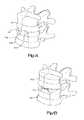
- the human vertebral columnhouses the spinal cord in its spinal canal.
- the vertebral columnis made up of a plurality of vertebrae.
- a typical vertebraincludes two primary parts, including an anterior portion that includes the vertebral body, and a posterior portion that encloses the foramen.
- Each vertebral bodydefines superior and inferior vertebral endplates that, such that adjacent vertebrae define an intervertebral space that includes disc material between the respective endplates.
- spinal fusionis a widely accepted surgical treatment for symptomatic lumbar and cervical degenerative disc disease.
- Early fusion proceduresused an implant made of bone from a patient's hip or a cadaver bone as a spacer in the intervertebral space so as to properly position the adjacent vertebrae until the vertebrae were fused together.
- More modern proceduresuse implants made from a material having a relatively low modulus of elasticity to encourage bone growth.
- the implantcan contain some of the patient's own bone, e.g., within apertures of the implant.
- Radiolucent materialssuch as polyetheretherketone (PEEK), ultra-high molecular weight polyethylenes (UHMWPE) or polysulfones (PSU). It can be desirable for the material to have a modulus of elasticity between 3 and 5 GPa.
- PEEKpolyetheretherketone
- UHMWPEultra-high molecular weight polyethylenes
- PSUpolysulfones
- an intervertebral implantis configured to be fixed in an intervertebral space defined by a first vertebral body and a second vertebral body.
- the intervertebral implantincludes an implant body sized to be inserted into an intervertebral space, and a fixation assembly configured to be attached to the implant body.
- the fixation assemblyincludes a housing that defines a first vertebral body facing surface and a second vertebral body facing surface spaced from the first vertebral body facing surface along a transverse direction.
- the housingdefines a channel.
- the fixation assemblyfurther includes a first superior staple and a second inferior staple that is transversely opposite the first superior staple.
- each stapleis supported in the channel such that each staple includes a crossbar and a pair of spaced that extend transversely out from the crossbar.
- Each crossbardefines respective first and second cam surfaces.
- the intervertebral implantfurther includes an actuator that is configured to translate along a distal direction within the housing that is substantially orthogonal to the transverse direction. The actuator is configured to substantially simultaneously engage the first and second cam surfaces so as to cause terminal ends of the pins of the first staple to translate in the transverse direction.
- FIG. 1Ais a perspective view of a pair of vertebral bodies separated by an intervertebral space
- FIG. 1Bis a perspective view of the vertebral bodies illustrated in FIG. 1 , and an intervertebral implant inserted into the intervertebral space between the two vertebral bodies;
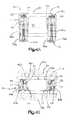
- FIG. 2Ais a perspective view of an intervertebral implant including an implant body and a fixation assembly connected to the intervertebral implant, showing the fixation assembly in accordance with one embodiment in a retracted position;
- FIG. 2Bis a perspective view of the intervertebral implant as illustrated in FIG. 2A , showing the fixation assembly in an extended position;
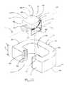
- FIG. 2Cis an exploded assembly view of the intervertebral implant illustrated in FIG. 2A , showing the connection of the fixation assembly to the implant body;
- FIG. 2Dis a top plan view of the intervertebral implant illustrated in FIG. 2A having portions removed for the purposes of clarity;
- FIG. 2Eis a front elevation view of the intervertebral implant as illustrated in FIG. 2A , having portions removed for the purposes of clarity, shown in an intervertebral space;
- FIG. 2Fis a side view of the intervertebral implant as illustrated in FIG. 2E , having portions removed for the purposes of clarity;
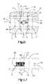
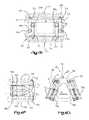
- FIG. 2Gis a perspective view of the fixation assembly as illustrated in FIG. 2B ;
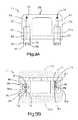
- FIG. 2His a top plan view of the intervertebral implant as illustrated in FIG. 2B , having portions removed for the purposes of clarity;
- FIG. 2Iis a front elevation view of the intervertebral implant as illustrated in FIG. 2B , having portions removed for the purposes of clarity, shown in an intervertebral space;
- FIG. 2Jis a side view of the intervertebral implant as illustrated in FIG. 2I , having portions removed for the purposes of clarity;
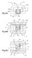
- FIG. 3Ais a top plan view of an intervertebral implant including an implant body and a fixation assembly constructed in accordance with an alternative embodiment, having portions removed for the purposes of clarity, showing the fixation assembly in a retracted position;
- FIG. 3Bis a front elevation view of the intervertebral implant as illustrated in FIG. 3A , having portions removed for the purposes of clarity, shown in an intervertebral space;
- FIG. 3Cis a side elevation view of the intervertebral implant as illustrated in FIG. 3B , having portions removed for the purposes of clarity;
- FIG. 3Dis a top plan view of the intervertebral plant illustrated in FIG. 3A , but showing the fixation assembly in an extended position;
- FIG. 3Eis a front elevation view of the intervertebral implant as illustrated in FIG. 3D , having portions removed for the purposes of clarity, shown in an intervertebral space;
- FIG. 3Fis a side elevation view of the intervertebral implant as illustrated in FIG. 3D , having portions removed for the purposes of clarity;
- FIG. 3Gis a top plan view of an intervertebral implant similar to the intervertebral implant as illustrated in FIG. 3D , but constructed in accordance with an alternative embodiment;
- FIG. 4Ais a top plan view of an intervertebral implant including an implant body and a fixation assembly constructed in accordance with an alternative embodiment, having portions removed for the purposes of clarity, showing the fixation assembly in a retracted position;
- FIG. 4Bis a front elevation view of the intervertebral implant as illustrated in FIG. 4A , having portions removed for the purposes of clarity, shown in an intervertebral space;
- FIG. 4Cis a side elevation view of the intervertebral implant as illustrated in FIG. 4B , having portions removed for the purposes of clarity;
- FIG. 4Dis a top plan view of the intervertebral implant illustrated in FIG. 4A , but showing the fixation assembly in an extended position;
- FIG. 4Eis a front elevation view of the intervertebral implant as illustrated in FIG. 4D , having portions removed for the purposes of clarity, shown in an intervertebral space;
- FIG. 4Fis a side elevation view of the intervertebral implant as illustrated in FIG. 4D , having portions removed for the purposes of clarity;
- FIG. 4Gis a top plan view of an intervertebral implant similar to the intervertebral implant as illustrated in FIG. 4D , but constructed in accordance with an alternative embodiment;
- FIG. 5Ais a top plan view of an intervertebral implant including an implant body and a fixation assembly constructed in accordance with an alternative embodiment, having portions removed for the purposes of clarity, showing the fixation assembly in a retracted position;
- FIG. 5Bis a front elevation view of the intervertebral implant as illustrated in FIG. 5A , having portions removed for the purposes of clarity, shown in an intervertebral space;
- FIG. 5Cis a side elevation view of the intervertebral implant as illustrated in FIG. 5B , having portions removed for the purposes of clarity;
- FIG. 5Dis a top plan view of the intervertebral plant illustrated in FIG. 5A , but showing the fixation assembly in an extended position;
- FIG. 5Eis a front elevation view of the intervertebral implant as illustrated in FIG. 5D , having portions removed for the purposes of clarity, shown in an intervertebral space;
- FIG. 5Fis a side elevation view of the intervertebral implant as illustrated in FIG. 5D , having portions removed for the purposes of clarity;
- FIG. 5Gis a top plan view of an intervertebral implant similar to the intervertebral implant as illustrated in FIG. 5D , but constructed in accordance with an alternative embodiment;
- FIG. 6Ais a top plan view of an intervertebral implant including an implant body and a fixation assembly constructed in accordance with an alternative embodiment, having portions removed for the purposes of clarity, showing the fixation assembly in an extended position;
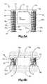
- FIG. 6Bis a front elevation view of the intervertebral implant as illustrated in FIG. 6A , shown disposed in an intervertebral space and in a retracted position;
- FIG. 6Cis a front elevation vie of the intervertebral implant as illustrated in FIG. 6B , having portions removed for the purposes of clarity;
- FIG. 6Dis a side elevation view of the intervertebral implant as illustrate FIG. 6C , having portions removed for the purposes of clarity;
- FIG. 6Eis a front elevation view of the intervertebral implant as illustrated in FIG. 6A , having portions removed for the purposes of clarity, showing the fixation assembly in an extended position;
- FIG. 6Fis a side elevation view of the intervertebral it plant as illustrated in FIG. 6E , having portions removed for the purposes of clarity;
- FIG. 6Gis a side elevation view of an extractor of the intervertebral implant illustrated in FIG. 6A , configured to iterate the fixation assembly to the retracted position;
- FIG. 6His a top plan view of the extractor illustrated in FIG. 6G ;
- FIG. 6Iis a side elevation view of the implant as illustrated in FIG. 6A , showing the extractor installed with the fixation assembly in an extended position, having portions removed for the purposes of clarity;
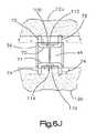
- FIG. 6Jis a front elevation view of the intervertebral implant as illustrated in FIG. 6I , having portions removed for the purposes of clarity;
- FIG. 6Kis a front elevation view of the intervertebral implant as illustrated in FIG. 6I , showing an actuator of the fixation assembly, and showing the fixation assembly in a retracted position;
- FIG. 6Lis a front elevation view of the intervertebral implant as illustrated in FIG. 6K , but showing portions removed for the purposes of clarity;
- FIG. 6Mis a side elevation view of the intervertebral implant as illustrated in FIG. 6L , showing portions removed for the purposes of clarity;
- FIG. 6Nis a top plan view of the intervertebral implant as illustrated in FIG. 6M , showing portions removed for the purposes of clarity;
- FIG. 7Ais a top plan view of an intervertebral implant including an implant body and a fixation assembly constructed in accordance with an alternative embodiment, having portions removed for the purposes of clarity, showing the fixation assembly in a retracted position;
- FIG. 7Bis a front elevation view of the intervertebral implant as illustrated in FIG. 7A , showing portions removed for the purposes of clarity, disposed in an intervertebral space;
- FIG. 7Cis a side elevation view of the intervertebral implant as illustrated in FIG. 7B , showing portions removed for the purposes of clarity;
- FIG. 7Dis a top plan view of the intervertebral implant illustrated in FIG. 7A , showing the fixation assembly in an extended position;
- FIG. 7Eis a front elevation view of the intervertebral implant as illustrated in FIG. 7D , showing portions removed for the purposes of clarity, disposed in an intervertebral space;
- FIG. 7Fis a side elevation view of the intervertebral implant as illustrated in FIG. 7E , showing portions removed for the purposes of clarity;
- FIG. 8Ais a side elevation view of an intervertebral implant similar to the intervertebral implant illustrated in FIG. 7A , but constructed in accordance with an alternative embodiment, having portions removed for the purposes of clarity;
- FIG. 8Bis a front elevation view of the intervertebral implant illustrated in FIG. 8A ;
- FIG. 9Ais a top plan view of an intervertebral implant including an implant body and a fixation assembly constructed in accordance with an alternative embodiment, having portions removed for the purposes of clarity, showing the fixation assembly in a retracted position;
- FIG. 9Bis a front elevation view of the intervertebral implant as illustrated in FIG. 9A , having portions removed for the purposes of clarity, shown in an intervertebral space;
- FIG. 9Cis a front elevation view of the intervertebral implant illustrated in FIG. 9B , having portions removed for the purposes of clarity, showing the fixation assembly in an extended position;
- FIG. 9Dis a front elevation view of an intervertebral implant similar to that illustrated in FIG. 9B , but showing a bone fixation member of the fixation assembly constructed in accordance with an alternative embodiment;
- FIG. 9Eis a front elevation view of the intervertebral implant as illustrated in FIG. 9D , showing the fixation assembly in an extended position;
- FIG. 10Ais a top plan view of an intervertebral implant including an implant body and a fixation assembly constructed in accordance with an alternative embodiment, having portions removed for the purposes of clarity, showing the fixation assembly in a retracted position;
- FIG. 10Bis a front elevation view of the intervertebral implant illustrated in FIG. 10A , having portions removed for the purposes of clarity, shown in an intervertebral space, and showing the fixation assembly in a retracted position;
- FIG. 10Cis a front elevation view of the intervertebral implant as illustrated in FIG. 10B , but showing the fixation assembly in an extended position;
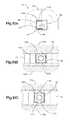
- FIG. 11Ais a top plan view of an intervertebral implant including an implant body and a fixation assembly constructed in accordance with an alternative embodiment, having portions removed for the purposes of clarity, showing the fixation assembly in a retracted position;
- FIG. 11Bis a front elevation view of the intervertebral implant illustrated in FIG. 11A , having portions removed for the purposes of clarity, shown in an intervertebral space, and showing the fixation assembly in a retracted position;
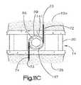
- FIG. 11Cis a front elevation view of the intervertebral implant as illustrated in FIG. 11B , but showing the fixation assembly in an extended position;
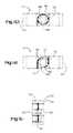
- FIG. 11Dis a front elevation view of the intervertebral implant illustrated in FIG. 11B , showing the intervertebral implant in an as-assembled position;
- FIG. 11Eis a front elevation view of the intervertebral implant illustrated in FIG. 11B , showing the intervertebral implant in an as-supplied position;
- FIG. 11Fis a top plan view of the intervertebral implant as illustrated in FIG. 11E ;
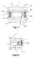
- FIG. 12Ais a top plan view of an intervertebral implant including an implant body and a fixation assembly constructed in accordance with an alternative embodiment, having portions removed for the purposes of clarity, showing the fixation assembly in a retracted position;
- FIG. 12Bis a front elevation view of the intervertebral implant as illustrated in FIG. 12A , having portions removed for the purposes of clarity, shown in an intervertebral space;
- FIG. 12Cis a front elevation view of the intervertebral implant as illustrated in FIG. 12B , but showing the fixation assembly in an extended position;
- FIG. 13Ais a top plan view of an intervertebral implant including an implant body and a fixation assembly constructed in accordance with an alternative embodiment, having portions removed for the purposes of clarity, showing the fixation assembly in a retracted position;
- FIG. 13Bis a front elevation view of the intervertebral implant as illustrated in FIG. 13A , having portions removed for the purposes of clarity, shown in an intervertebral space;
- FIG. 13Cis a side elevation view of the intervertebral implant as illustrated in FIG. 13B , having portions removed for the purposes of clarity;
- FIG. 13Dis a front elevation view of the intervertebral implant as illustrated in FIG. 13B , showing the fixation assembly in an extended position;
- FIG. 13Eis a side elevation view of the intervertebral implant as illustrated in FIG. 13D , having portions removed for the purposes of clarity;
- FIG. 13Fis a schematic top plan view of an intervertebral implant similar to the intervertebral implant as illustrated in FIG. 13A but constructed in accordance with an alternative embodiment;
- FIG. 14Ais a top plan view of an intervertebral implant including an implant body and a fixation assembly constructed in accordance with an alternative embodiment, having portions removed for the purposes of clarity, showing the fixation assembly in a retracted position;
- FIG. 14Bis a front elevation view of the intervertebral implant as illustrated in FIG. 14A , having portions removed for the purposes of clarity, shown in an intervertebral space;
- FIG. 14Cis a front elevation view of the intervertebral implant as illustrated in FIG. 14B , showing the fixation assembly in an extended position;
- a first superior vertebral body 12 adefines a superior vertebral endplate 13 a of an intervertebral space 14
- an adjacent second inferior vertebral body 12 bdefines an inferior vertebral endplate 13 b of the intervertebral space 14
- the intervertebral space 14is disposed between the vertebral bodies 12 a - b
- the vertebral bodies 12 a - bcan be anatomically adjacent vertebral bodies, or can remain after a discectomy has been performed that removed a vertebral body from a location between the vertebral bodies 12 a - b .
- the intervertebral space 14is illustrated after a discectomy, whereby the disc material has been removed to prepare the intervertebral space 14 to receive an orthopedic implant, such as the intervertebral implant 10 illustrated in FIG. 2 .
- the implant 10is configured to be inserted into the intervertebral space 14 , and achieve restoration of height while maintaining mobility.
- the intervertebral space 14can be disposed anywhere along the spine as desired.
- the implant 10can be sized as desired so as to be implantable in an intervertebral disc space in any region of the spine, including the lumbar region, thoracic region, cervical region, sacral region, and coccygeal region.
- the implant 10 and various components of the implant 10are described herein extending horizontally along a longitudinal direction L and a lateral direction A, and vertically along a transverse direction T.
- the terms “lateral,” “longitudinal,” and “transverse”are used to describe the orthogonal directional components of various components.
- the lateral direction A and longitudinal direction Lare angularly offset, for instance substantially orthogonal, with respect to each other and with respect to the transverse direction T. It should be appreciated that while the longitudinal and lateral directions are illustrated as extending along a horizontal plane, and that the transverse direction is illustrate as extending along a vertical plane, the planes that encompass the various directions may differ during use.
- the transverse direction Textends generally along the superior-inferior (or cranial-caudal) direction, while the plane defined by the longitudinal direction L and lateral direction A lie generally in the anatomical plane defined by the anterior-posterior direction, and the medial-lateral direction, respectively.
- the directional terms “vertical” and “horizontal”are used to describe the implant 10 and its components as illustrated merely for the purposes of clarity and illustration.
- the intervertebral implant 10includes an implant body 20 and a fixation assembly 22 configured to secure the implant body 20 to the first and second vertebral bodies 12 a and 12 b in the intervertebral space 14 .
- the implant 10 and components thereofcan be formed from any of a variety of biocompatible materials, such as cobalt chromium molybdenum (CoCrMo), titanium and titanium alloys, stainless steel, ceramics, or polymers such as polyetheretherketone (PEEK), ultra-high molecular weight polyethylenes (UHMWPE) or polysulfones (PSU), bioresorbable materials, and bonegraft (for example allograft and xenograft).
- a coatingmay be added or applied to the implant 10 to improve physical or chemical properties. The coatings may help to ensure bony in or on growth or medication. Examples of coatings include plasma-sprayed titanium coating or hydroxyapatite.
- the implant body 20defines a front end 24 and a longitudinally opposed rear end 26 , a top end 28 and a transversely opposed bottom end 30 , and opposed lateral sides 32 and 34 .
- the top and bottom ends 28 and 30can be configured to face the corresponding vertebral endplates 13 a and 13 b of the superior and inferior vertebral bodies 12 a and 12 b , respectively.
- the top and bottom ends 28 and 30can be configured to abut the corresponding vertebral endplates 13 a and 13 b .
- the implant 10can be inserted into the intervertebral space 14 along an insertion direction which can be an anterior-posterior approach (for instance when the vertebral bodies 12 a and 12 b are cervical vertebral bodies) in an orientation such that the front longitudinal end 24 is anterior to the rear longitudinal end 26 .
- the implant bodycan be sized and shaped as desired, and is illustrated as substantially “D” shaped, such that the front end 24 extends substantially straight in the lateral direction A, and the lateral sides 32 and 34 curve toward each other in a rearward direction to the rear end 26 .
- the implant body 20defines a substantially central “D” shaped central opening 25 that extends transversely into (through as illustrated) the implant body 20 .
- the central opening 25can receive any suitable bone growth promoting material, such as allograft and xenograft to promote bone growth with the vertebral bodies 12 a - b after implantation of the implant 10 into the intervertebral space 14 .
- the implant body 20can be solid as illustrated, or can define perforations that extend into or through the implant body 20 that can, for instance, receive the bone growth promoting material.
- the implant body 20defines a transverse height H between the top and bottom ends 28 and 30 .
- the height Hcan be substantially constant from the front end 24 to the rear end 26 , or can be variable from the front end 24 to the rear end 26 so as to impart or restore a lordotic curvature to the vertebral bodies 12 a and 12 b .
- the height Hcan decrease in a rearward direction from the front end 24 toward the rear end 26 , or can increase in the rearward direction.
- the height Hcan be constant or variable between the lateral sides 32 and 34 as desired.
- top and bottom ends 28 and 30can be substantially planar, or can be curved, undulated, or otherwise shaped as desired so as to correspond to the vertebral endplates 13 a and 13 b .
- a kit of implants 10can also be provided, each having a plurality of implant bodies 20 of different shapes or sizes.
- the kitcan include a plurality of implant bodies 20 of different heights H, such that at least one of the implant bodies 20 in the kit can correspond with the corresponding different height of intervertebral spaces along the vertebral column of a given patient, or of an intervertebral space of different patients.
- the fixation assembly 22includes a fixation housing 36 that is configured to be mounted or otherwise connected to the implant body 20 .
- the fixation housing 36supports, either directly or indirectly, at least one bone or vertebral fixation member 38 and at least one actuator 40 that is configured to iterate the fixation assembly 22 , and particular the at least one fixation member 38 , between a retracted position illustrated in FIG. 2A and an extended position illustrated in FIG. 2B so as to fix the fixation assembly 22 and thus the implant 10 to the vertebral bodies 12 a and 12 b .
- the fixation housing 36defines a front end 42 and a longitudinally opposed rear end 44 , a top end 46 and a transversely opposed bottom end 48 , and opposed lateral side 50 and 52 .
- the top and bottom ends 46 and 48can be configured to face the corresponding vertebral endplates 13 a and 13 b of the superior and inferior vertebral bodies 12 a and 12 b , respectively. In some embodiments, the top and bottom ends 46 and 48 can be configured to abut the corresponding vertebral endplates 13 a and 13 b .
- the front end 42defines a proximal end of the fixation housing 36
- the rear end 44defines a distal end of the fixation housing 36 that is spaced from the proximal end in the insertion direction along a central longitudinal axis 37 .
- the fixation housing 36 and the implant body 20include respective complementary engagement members 54 and 56 that can be configured as desired to mount or otherwise connect the fixation housing 36 to the implant body 20 .
- the engagement member 54 of the fixation assembly 22is configured as a transversely elongate rail 58 that projects laterally out from the sides 50 and 52 of the fixation housing 36 .
- the rails 58can terminate above the bottom end 48 of the fixation housing 36 .
- the complementary engagement member 56 of the implant body 20is configured as a pair of transversely elongate slots 60 sized to receive the rails 58 .
- the slot 60can terminate above the bottom end 30 of the implant body 20 .
- the slots 60are disposed on opposed sides of a pocket 62 that is defined by the implant body 20 and sized to receive the fixation housing 36 .
- the fixation assembly 22can be can be connected to the implant body 20 by inserting the fixation housing 36 into the pocket 62 of the implant body 20 such that the rails 58 are received in the slots 60 .
- the fixation housing 36can define a longitudinal length greater than the front end 24 of the implant body 20 , such that the fixation housing 36 extends longitudinally into the central opening 25 .
- the rails 58 and slots 60can be sized such that the top and bottom ends 46 and 48 of the fixation housing 36 are substantially aligned or flush with the top and bottom ends 28 and 30 of the implant body 20 .
- top and bottom ends 46 and 48 of the fixation housing 36can be configured to abut the vertebral endplates 13 a and 13 b .
- part or of the top and bottom ends 28 and 30 of the implant body 20 and/or the top arid bottom ends 46 and 48 of the fixation housingcan be recessed with respect to the vertebral endplates 13 a and 13 b .
- top ends 28 and 46 and bottom ends 30 and 48abut or are recessed from the respective vertebral endplates 13 a and 13 b , they can face a direction having a transverse directional component, such that it can be said that the top ends 28 and 46 and bottom ends 30 and 48 face the vertebral bodies 12 a and 12 b and thus define vertebral body facing surfaces.
- the engagement members 54 and 56can be configured as desired to facilitation the connection of the fixation assembly 20 to the implant body 20 .
- the fixation assembly 22can be integral with the implant body 20 .
- the fixation assembly 22includes at least one aperture 63 defined by the fixation housing 36 that receives the actuator 40 and at least one channel that receives the at least one fixation member 38 .
- the fixation housing 36defines a first pair of laterally spaced superior channels 64 and a second pair of laterally spaced inferior channels 65 that can be vertically aligned with the superior channels 64 .
- the channels 64 and 65can extend in any direction as desired, and extend in a direction having both longitudinal and transverse directional components in accordance with the illustrated embodiment.
- the superior channels 64extend longitudinally and transversely upwards so as to define a first proximal end that extends from the proximal end 42 of the fixation housing 36 to a second distal end that extends to the top end 46 .
- the inferior channels 65extend longitudinally and transversely down so as to define a first proximal end that extends from the proximal end 42 of the fixation housing 36 to the distal end that extends to the bottom end 48 .
- the distal ends of the channels 64 and 65are thus transversely and longitudinally displaced with respect to the respective proximal ends of the channels 64 and 65 .
- the channels 64 and 65extend laterally into the sides 50 and 52 of the fixation housing 36 , though they can be alternatively positioned as desired.
- the fixation assembly 22can include a pair of cover plates 66 that are attached to the sides 50 and 52 of the fixation housing 36 so as to laterally cover and laterally close the channels 64 and 65 .
- the cover plates 66can include the engagement rails 58 as described above.
- the fixation member 38can be provided as a first staple 68 that defines a proximal end 77 and an opposed distal or terminal end 79 that, in turn, defines a corresponding tip 73 that is configured to be inserted into a corresponding vertebral body (e.g., through the endplate) so as to fix the fixation assembly 22 and thus the implant 10 to the vertebral body.
- the staple 68includes a bass in the form of a crossbar 70 at the proximal end 77 and at least a first pair of laterally spaced pins 72 that extend out from the crossbar 70 at any location, such as at opposed outer ends of the crossbar 70 as illustrated.
- the implant 10can include a second fixation member provided as a second staple 69 can further include a second pair of laterally spaced pins 74 that extend out from a second crossbar 71 at any location, such as at opposed outer ends of the crossbar 71 as illustrated.
- the pins 72 and 74are attached to the respective crossbars 70 and 75 at their proximal ends, and define the tips 73 at their distal ends.
- the pins 72 and 74can be entirely recessed in the fixation housing 36 such that the tips 73 do not extend out from the fixation housing 36 .
- the tips 73 of the first and second pairs of pins 72 and 74can extend into the vertebral bodies 12 a and 12 b when the fixation member 38 is in the extended position.
- the implant 10can include a pair of fixation members that define respective pairs of pins 72 and 74 , the first pair of pins 72 defining a tip 73 at its distal or terminal end that is configured to extend into the first vertebral body 12 a in the extended position, and the second pair of pins 72 defining a tip that is configured to extend into the second vertebral body 12 b in the extended position.
- the first pair of pins 72extends superiorly and longitudinally distally from the crossbar 70 in the superior channels 64
- the second pair of pins 74extends inferiorly and longitudinally distally from the crossbar 71 in the inferior channels 65 .
- the channels 64 and 65can curve along their length along a constant radius such that the pins 72 and 74 can be made from any suitable rigid material, or the channels 64 and 65 can define different curvatures along their length, such that the pins 72 and 74 can be made of any suitable flexible material.
- the pins 72 and 74can be made from titanium or nitinol (nickel titanium). As will be described in more detail below, the pins 72 and 74 are movable within the channels 64 and 65 from the retracted position to the extended position whereby the distal ends of the pins 72 and 74 extend out from the fixation housing 36 and into the corresponding vertebral bodies 12 a and 12 b when the implant 10 is disposed in the intervertebral space 14 . The distal ends of the pins 72 and 74 can extend out from the fixation housing 36 substantially in the transverse direction T.
- the actuator 40is configured to iterate the fixation member 38 from the retracted position to the extended position.
- the actuator 40can be provided as a screw 76 that defines external threads 78 along part or all of the length of a screw shaft 89 that engages corresponding internal threads 80 of the aperture 63 . Accordingly, the screw 76 can translate distally in the aperture 63 and thus the fixation housing 36 as the screw 76 is rotated in the aperture 63 relative to the fixation housing 36 .
- the screw 76can translate along a direction that has a longitudinal directional component (e.g., distally) from a disengaged position to an engaged position.
- the fixation member 38is in the retracted position.
- the screw 76moves to the engaged position.
- the screw 76defines a first engagement member illustrated as a groove 82 that can extend circumferentially or about an arc about the screw 76 .
- the crossbars 70 and 71define respective apertures, which can be cylindrical, that extends longitudinally through the crossbars 70 and 71 , such that the crossbars 70 and 71 define a respective collars 84 and 85 that are sized to be inserted into the groove 82 .
- the collars 84 and 85can be circumferentially sized slightly greater than the groove 82 such that the screw 76 is rotatable with respect to the collars.
- the longitudinal dimension of the collars 84 and 85can be substantially equal to that of the groove 82 such that the collars 84 and 85 , and thus the staples 68 and 69 , are substantially longitudinally fixed to the screw 76 such that the staples 68 and 69 translate as the screw 76 translates in the aperture 63 .
- the pins 72 and 74translate distally in the respective channels 64 and 65 to the extended position as the screw 76 translates, whereby the distal ends of the pins 72 and 74 , and thus the tips 73 , extend transversely out from the fixation housing 36 to a location transversely out from at least a portion of the implant body 20 .
- the distal ends of the channels 64 and 65can extend substantially transversely such that the portion of the pins 72 and 74 that extend out from the channels 64 and 65 , including the tips 73 , can be directed substantially in the transverse direction into the respective vertebral bodies 12 a and 12 b.
- the screw 76defines an engagement member illustrated as a socket 86 that extends longitudinally into the proximal end of the screw 76 .
- the socket 86is illustrated as a hexagonal in shape, though it could be shaped as any suitable polygonal shape, including a “plus” shape, a “dash” shape, or any alternative shape as desired. Because the socket 86 extends longitudinally into the screw 76 , the socket 86 defines a depth that is substantially parallel to the insertion direction of the implant 10 into the intervertebral space 14 .
- an anterior approach into the intervertebral space 14can facilitate both insertion of the implant 10 into the intervertebral space and movement of the actuator 40 from the disengaged position to the engaged position, thereby correspondingly causing the fixation member 38 to move from the retracted position to the extended position.
- an actuator toolsuch as a hex drive
- a hex drivecan be inserted into the socket 86 and rotated, either manually or automatically so as to cause the screw 76 to rotate and translate distally relative to the fixation housing 36 .
- the proximal end of the screw 76extends longitudinally out to a location proximal of the front end 42 of the fixation housing 36 when the screw is in the disengaged position.
- the screw 76translates distally to the engaged position, the screw 76 translates distally until the screw 76 reaches the engaged position.
- the aperture 63can terminate at a location that prevents further translation of the screw 76 once the screw 76 has reached the engaged position.
- proximal end of the screw 76is substantially flush with the front end 42 of the fixation housing when the screw 76 is in the engaged position.
- the fixation member 38likewise translates distally, which causes the pins 72 and 74 to travel distally in their respective channels 64 and 65 , thereby causing the tips 73 to initially protrude transversely from the upper and lower ends 46 and 48 , respectively, of the fixation housing 36 .
- the tips 73extend increasingly out from the fixation housing 36 until the screw 76 is in the engaged position, at which point the tips 73 of the pins 72 and 74 are fully extended out from the fixation housing 36 and into the vertebral bodies 12 a and 12 b.
- the screw 76can be rotated relative to the fixation housing 36 in a second opposite direction, thereby causing the screw 76 to translate proximally from the engaged position to the disengaged position. As the screw 76 translates proximally, the fixation member 38 likewise translates proximally, thereby causing the tips of the pins 72 and 74 to retract toward the respective channels 64 and 65 .
- the tips 73 of the pins 72 and 74can be recessed with respect to the vertebral bodies 12 a and 12 b , and fully retracted in the respective channels 64 and 65 , at which point the implant 10 can be removed from the intervertebral space 14 .
- the implant 10can be constructed in accordance with any alternative embodiment as desired having at least one fixation member that is configured to move between a retracted position to an extended position as described above.
- fixation memberthat is configured to move between a retracted position to an extended position as described above.
- the fixation assembly 22 of the implant 10is illustrated in accordance with an alternative embodiment, whereby the fixation housing 36 includes a pair of laterally spaced fixation housing segments 36 a and 36 b that are connected to the lateral sides 32 and 34 of the implant body 20 .
- Each housing segment 36 a and 36 bdefines an aperture 63 that receives an actuator 40 illustrated as a screw 76 in the manner described above.
- the superior channel 64extends centrally from one of the apertures 63 in the housing segment 36 b
- the inferior channel 65extends centrally from the other aperture 63 in the housing segment 36 a .
- Each of the screws 76can define a bore 81 that extends centrally into their distal ends, such that the proximal ends of at least a first fixation member illustrated as a first pin 72 extends into the central bore 81 of the screw 76 disposed in the housing segment 36 a .
- the first pin 72further extends into the superior channel 64 .
- the proximal ends of at least a second fixation member illustrated as a pin 74extends into the central bore 81 of the screw 76 disposed in the housing segment 36 b , such that the second pin further extends into the inferior channel 64 .
- the proximal ends of the pins 72 and 74are rotatably coupled to the respective screws inside the bore 81 , and can be attached to the screws 76 via adhesive or weldments, or can alternatively be integrally connected to the screws 76 .
- the pins 72 and 74are coupled to the respective screws 76 with respect to both translation and rotation, such that the pins 72 and 74 both rotate and translate along with the respective screws 76 to which they are connected.
- the pins 72 and 74extend into the respective channels 64 and 65 , which extend superiorly and inferiorly, respectively, and longitudinally distally as described above.
- the screws 76translate as they rotate in the housing 36 in the manner described above, which causes the pins 72 and 74 to rotate as they travel distally in the respective channels 64 and 65 .
- the tips 73therefore also rotate as they translate out from the fixation housing 36 .
- the pins 72 and 74can each include a cutting bit, for instance cutting flutes 83 , at their tips 73 no as to facilitate cutting into the vertebral bodies 12 a and 12 b as the pins 72 rotate and translate from their retracted positions to their extended positions.
- the screws 76 , channels 64 and 65 , and pins 72 and 74can extend substantially parallel to each other (longitudinally as illustrated in FIGS. 3A-F ), or can be angularly offset with respect to each other.
- the screws 76 and the channels 64 and 65 , and thus the pins 72 and 74can converge toward each other along a direction from their proximal ends to their distal ends as illustrated in FIG. 3G .
- the channels 64 and 65can diverge away from each other along a direction from their proximal ends to their distal ends.
- the implant 10can include a pair of screws 76 at each lateral side 32 and 34 .
- each side 32 and 34can include a superior screw 76 coupled to a superior pin in the manner described above, and an inferior screw 76 located inferior with respect to the superior screw and coupled to an inferior pin in the manner described above, such that each lateral side of the implant body 20 can be fixed to both the superior vertebral body 12 a and the inferior vertebral body 12 b.
- the fixation assembly 22 of the implant 10is illustrated in accordance with an alternative embodiment, whereby the laterally spaced fixation housing segments 36 a and 36 b each include a superior aperture 63 a and an inferior aperture 63 b that each receive an actuator 40 illustrated as a superior screw 76 a and an interior screw 76 b in the manner described above.
- the superior aperture 63 a and the inferior aperture 63 bcan be laterally displaced from each other by a distance at least equal to the thickness of the channels 64 and 65 .
- the superior channel 64can extend from the inferior aperture 63 b and the inferior channel 65 can extend front the superior aperture 63 a , such that the channels 64 and 65 in each housing segment 36 a and 36 b cross over each other and can be longitudinally and transversely aligned without interfering with each other.
- the superior channels 64extend centrally from the inferior apertures 63 in the housing segments 36 a and 36 b
- the inferior channels 65extend centrally from the apertures 63 in the housing segments 36 a and 36 b
- Each of the screws 76 a and 76 bcan define a bore 81 that extends centrally into their distal ends.
- the proximal ends of at least a first fixation member 38such as a pair of first fixation members illustrated as a pair of first pins 72 extends into the central bore 81 of the corresponding pair of the inferior screws 76 b that are disposed in the inferior apertures 63 b and aligned with the superior channels 64 .
- the first pins 72further extend into the superior channels 64 from the inferior screws 76 b .
- a second fixation membersuch as a pair of second fixation members illustrated as a pair of second pins 74 extends into the central bore 81 of the corresponding pair of superior screws 76 a that are disposed in the superior apertures 63 a and aligned with the inferior channels 65 .
- the second pins 74further extend into the inferior channels 65 from the superior screws 76 a.
- the proximal ends of the pins 72 and 74are rotatably coupled to the respective screws 76 a and 76 b inside the bore 81 , and can be attached to the screws 76 a and 76 b via adhesive or weldments, or can alternatively be integrally connected to the screws 76 a and 76 b .
- the pins 72 and 74are coupled to the respective screws 76 b and 76 a with respect to both translation and rotation, such that the pins 72 and 74 rotate and translate with the respective screws 76 b and 76 a to which they are connected.
- the pins 72extend into the superior channels 64 from the inferior screws 76 b
- the pins 74extend into inferior channels 65 from the superior screws 76 a.
- Both channels 64 and 65extend from the respective apertures 63 b and 63 a in a direction having both longitudinal and transverse directional components.
- the proximal ends of the superior channels 64are inferior with respect to the proximal ends of the inferior channels 65
- the distal ends of the superior channels 64are superior with respect to the superior ends of the inferior channels 65 .
- the distal ends of the superior channels 64extend through the top end of the fixation housing 36 and/or implant body 20 .
- the distal ends of the inferior channels 64extend through the bottom end of the fixation housing 36 and/or implant body 20 .
- the screws 76translate as they rotate in the housing 36 in the manner described above, which causes the pins 72 and 74 to rotate as they travel distally in the respective channels 64 and 65 .
- the tips 73therefore also rotate as they translate out from the fixation housing 36 .
- the pins 72 and 74can each include a cutting bit, for instance cutting flutes 83 , at their tips 73 so as to facilitate cutting into the vertebral bodies 12 a and 12 b as the pins 72 rotate and translate from their retracted positions to their extended positions.
- the pins 72 that are connected to the inferior screws 76 bextend through the superior channels 64 such that the tips 73 extend transversely outward with respect to the fixation housing 36 and/or the implant body 20 along a direction having a transverse directional component into the superior vertebral body 12 a when the implant 10 is disposed in the intervertebral space 14 and the pins 72 have been iterated to their extended position.
- the pins 74 that are connected to the superior screws 76 aextend through the inferior channels 65 such that the tips 73 extend transversely outward with respect to the fixation housing 36 and/or the implant body 20 along a direction having a transverse directional component into the inferior vertebral body 12 b when the implant 10 is disposed in the intervertebral space 14 and the pins 74 have been iterated to their extended position.
- the channels 64 and 65can extend substantially parallel to each other (longitudinally as illustrated in FIGS. 4A-F ), or can be angularly offset with respect to each other. For instance, the channels 64 and 65 can converge toward each other along a direction from their proximal ends to their distal ends as illustrated in FIG. 4G . Alternatively still, the channels 64 and 65 can diverge away from each other along a direction from their proximal ends to their distal ends.
- the fixation assembly 22 of the implant 10is illustrated substantially as described with respect to FIGS. 4A-G , however the pins 72 and 74 can include external threads 87 along part or all of their length, for instance at the terminal end that extends transversely out from the fixation housing 36 . Accordingly, as the pins 72 and 74 rotate to their extended position, the threads 87 engage the vertebral bodies 12 a and 12 b .
- the threads 87can have a pitch that is the same or different than the pitch of the external threads 78 of the corresponding screws 76 .
- the pins 72 and 74are illustrated as integral with the screws 76 a and 76 b.
- the actuation assembly 22includes a pair of fixation members 38 in the form of a first superior staple 68 and a second inferior staple 69 .
- the first staple 68includes a base in the form of a crossbar 70 and at least a first pair of laterally spaced pins 72 that extend out from the crossbar 70 at any location, such as at opposed outer ends of the crossbar 70 as illustrated.
- the second staple 69can further include a second pair of laterally spaced pins 74 that extend out from base illustrated as a second crossbar 71 at any location, such as at opposed outer ends of the crossbar 71 as illustrated.
- the staples 68 and 69can be disposed in respective superior and interior channels 64 and 65 that can extend in any direction desired, such as the transverse direction as illustrated. It should be appreciated that the channels 64 and 65 can be continuous in a single channel, or bifurcated and separate as desired.
- the actuator 40can be provided as a screw 76 that is configured to iterate the fixation members 38 from the retracted position in which the tips 73 are recessed with respect to the fixation housing 36 and/or the implant body 20 to the extended position in which the tip 73 extend transversely out from the fixation housing 36 and/or the implant body 20 .
- the actuator 40can be provided as a screw 76 that defines external threads 78 along part or all of its length that engages corresponding internal threads 80 of the aperture 63 . Accordingly, the screw 76 can translate distally in the aperture 63 and thus the fixation housing 36 as the screw 76 is rotated in the aperture 63 relative to the fixation housing 36 .
- the screw 76defines a beveled distal tip 88 that tapers transversely inwardly along a longitudinal distal direction. During operation, the screw 76 can translate from a disengaged position to an engaged position. When the screw 76 is in the disengaged position, the fixation member 38 is in the retracted position. When the screw 76 moves to the engaged position, the screw 76 moves the fixation member 38 to the extended position.
- the respective crossbars 70 and 71are disposed adjacent each other, and thus separated by a first distance that can be equal to substantially zero such that the staples 68 and 69 abut each other.
- the crossbars 70 and 71can be round in cross-section or otherwise shaped so as to define respective first and second cam surfaces 90 and 92 that can extend transversely inward along a longitudinal distal direction so as to create a gap between a proximal portion of the crossbars 70 and 71 if they abut each other when in their retracted positions.
- the screw 76translate along the longitudinally distal direction, such that the screw 76 can engage, or ride along, the first and second cam surfaces 90 and 92 of the staples 68 and 69 , thereby causing the pins 72 and 74 to translate along the channel in a direction having a transverse directional component.
- the channels 64 and 65can guide the pins to translate pins 72 and 74 substantially in the transverse direction with respect to the fixation housing 36 .
- the beveled tip 88engages the cam surfaces 90 and 92 of the staples 68 and 69 .
- the tip 88biases the staples 68 and 69 transversely outward as the screw 76 continues to translate distally.
- the beveled tip 88can be said to define a third cam surface configured to engage the first and second cam surfaces 90 and 92 substantially simultaneously so as to cause terminal ends 73 of the pins 72 and 74 to translate in the transverse direction until the screw 76 reaches the engaged position.
- staples 68 and 69can be in their extended positions such that the pins 72 extend superiorly out the fixation housing 36 and the pins 74 extend inferiorly out the fixation housing 36 .
- the pins 72extend into the superior vertebral body 12 a and the pins 74 extend into the inferior vertebral body 12 b when the implant 10 is disposed in the intervertebral space 14 .
- the staples 68 and 69including the crossbars 70 and 71 and the pins 72 and 74 can be substantially rigid or flexible as desired.
- the tip 88 of the screw 76can be configured to bias the staples 68 and 69 transversely outward as the screw 76 moves in the longitudinally distal direction if either the cam surfaces 90 and 92 are angularly offset with respect to the transverse direction, or if tip 88 of the screw is angularly offset with respect to the transverse direction.
- all cam surfaces 90 and 92 along with the cam surface defined by the beveled tip 88are angularly offset with respect to the transverse direction.
- the cam surfacescan be substantially planar, curved, bent, or otherwise shaped as desired.
- the fixation assembly 22can further include a second actuator in the form of an extractor 96 that is configured to engage the crossbars of the first and second staples 68 and 69 so as to cause terminal ends 73 of the pins 72 of the first staple 68 to retract inferiorly into the fixation housing 36 and further to cause the terminal ends 73 of the pins 74 of the second staple 69 to retract superiorly into the housing.
- a second actuatorin the form of an extractor 96 that is configured to engage the crossbars of the first and second staples 68 and 69 so as to cause terminal ends 73 of the pins 72 of the first staple 68 to retract inferiorly into the fixation housing 36 and further to cause the terminal ends 73 of the pins 74 of the second staple 69 to retract superiorly into the housing.
- the extractor 96can be provided as a screw 98 that defines an externally threaded shaft 100 along part or all of its length that engages the internal threads 80 of the aperture 63 in the fixation housing 36 . Accordingly, the screw 98 can translate distally in the aperture 63 and thus the fixation housing 36 as the screw 98 is rotated in the aperture 63 relative to the fixation housing 36 .
- the screw 98further defines a collar 102 at its distal end that is rotatable with respect to the threaded shaft 10 .
- the collar 102defines at least one beveled surface such as a pair of beveled surfaces 104 and 106 that can be angularly offset with respect to the transverse direction.
- the beveled surfaces 104 and 106are tapered toward each other along a proximal direction opposite the distal direction of Insertion of the screw 98 .
- the crossbars 70 and 71can define respective first and second extraction cam surfaces 108 and. 110 that are configured to engage the beveled surfaces 104 and 106 , respectively, of the extractor 96 .
- the extraction cam surfaces 108 and 110can be provided by notches 112 and 114 that extend transversely inward into, but not through, the transverse outer surfaces of the crossbars 70 and 71 .
- the notches 112 and 114can be sized so as to receive the respective beveled surfaces 104 and 106 .
- the extraction cam surfaces 108 and 110can be angularly offset with respect to the transverse direction, or can extend in any direction as desired.
- the extraction cam surfaces 108 and 110 , and the beveled surfaces 104 and 106can extend substantially planar, can be curved, bent, or otherwise shaped as desired.
- the screw 76can be removed after the staples 68 and 69 have been iterated to their extended positions, or otherwise out from their retracted positions.
- the screw 98can translate distally in the fixation housing 36 from a disengaged position to an engaged position. When the screw 98 is in the disengaged position, the staples 68 and 69 remain in their extended position as actuated by the screw 76 . When the screw 98 moves to the engaged position, the screw 98 iterates the staples 68 and 69 to their retracted positions.
- the beveled surfaces 104 and 106contact the crossbars 70 and 71 , for instance in the notches 112 and 114 , which can remain in the fixation housing 36 when the staples 68 and 69 are in their fully extended positions.
- the fixation housing 36can define a channel that receives the collar so as to maintain the beveled surfaces 104 and 106 in alignment with the notches 112 and 114 as the screw 98 rotates in the fixation housing 36 .
- the crossbars 70 and 71ride along the beveled surfaces 104 and 106 .
- the beveled surfaces 104therefore bias the staples 68 and 69 so as to move transversely inward toward the central longitudinal axis 37 .
- the superior staple 68 and corresponding pins 72translate inferiorly until the pins 72 are removed from the superior vertebral body 12 a and recessed in the fixation housing 36 .
- the implant 10can then be removed from the intervertebral space 12 or repositioned in the intervertebral space 12 as desired.
- the inferior staple 69 and corresponding pins 74translate superiorly until the pins 74 are removed from the inferior vertebral body 12 b and recessed in the fixation housing.
- the beveled surfaces 104 and 106can be referred to as cam surfaces that cause the fixation members 38 to move in a direction from their extended positions toward their retracted positions.
- the extractor 96can be provided as a discrete actuator with respect to the actuator 40 .
- the extractor 96can be attachable to the actuator 40 or integrally formed with the actuator 40 , such that one longitudinal side of the actuator 40 defines the distal tip 88 and the opposed longitudinal side of the actuator 40 includes the collar 102 .
- the fixation assembly 22can be constructed in accordance with an alternative embodiment.
- the fixation assembly 22can include at least one actuator 40 that is configured to iterate at least one fixation member 38 between a retracted position and an extended position in the manner described above.
- the fixation assembly 22can further include a biasing member 1118 that is operably coupled between the actuator 40 and the fixation member 38 .
- the biasing member 118can be attached to the fixation member 38 at its distal end, and can move the fixation member 38 from the retracted position to the extended position under forces applied to the biasing member 118 by the actuator 40 .
- the at least one fixation member 38can be in the form of a first superior fixation member illustrated as a first superior staple 68 , and a second inferior fixation member illustrated as a second inferior staple 69 as described above.
- the first staple 68includes a base in the form of a crossbar 70 and at least a first pair of laterally spaced pins 72 that extend out from the crossbar 70 at any location, such as at opposed outer ends of the crossbar 70 as illustrated.
- the second staple 69can further include a second pair of laterally spaced pins 74 that extend out from a base in the form of a second crossbar 71 at any location, such as at opposed outer ends of the crossbar 71 as illustrated.
- the staples 68 and 69can be disposed in respective superior and inferior channels 64 and 65 that can extend in any direction desired, such as the transverse direction as illustrated. It should be appreciated that the channels 64 and 65 can be continuous in a single channel, or bifurcated and separate as desired.
- the actuator 40can be provided as a screw 76 that defines external threads 78 along part or all of the longitudinal length of the screw shaft 89 .
- the screw 76defines a screw head 91 that defines an outer cam surface 93 and is coupled to the distal end of the screw shaft 89 , and can have a cross-sectional dimension (e.g., diameter) greater than that of the screw shaft 89 .
- the threads 78engage corresponding internal threads 80 of the aperture 63 in the front end 42 of the fixation housing 36 . Accordingly, the screw 76 can translate distally in the aperture 63 and thus the fixation housing 36 as the screw 76 is rotated in the aperture 63 relative to the fixation housing 36 .
- the screw 76can translate from a disengaged position to an engaged position.
- the fixation member 38is in the retracted position.
- the screw 76moves to the engaged position, the screw 76 moves the fixation member 38 to the extended position.
- the biasing member 118includes a first superior flexible biasing arm 120 and a second inferior flexible biasing arm 122 .
- the arms 120 and 122define respective proximal ends 124 and 126 that extend transversely inward with respect to a pair of intermediate segments 132 and 134 that are tapered transversely toward each other along the distal longitudinal direction.
- the proximal ends 124 and 126are fixed to the fixation housing 36 at respective connection locations 123 and 125 via an adhesive, mechanical fastener, or friction fit, or any suitable alternative fixation.
- the arms 120 and 122define distal ends in the form of hooks 133 that are fastened to the crossbars 70 and 71 .
- the intermediate segments 132 and 134are connected between the proximal and distal ends of the flexible arms 120 and 122 .
- the intermediate segments 132 and 134are connected to the proximal ends 124 and 126 by a hinge 127 .
- the hooks 133are transversely spaced from each other by a distance, which can equal zero if they abut, that is less than the transverse dimension of the screw cam surface 93 when the staples 68 and 69 are in their retracted positions.
- the outer cam surface 93 of the screw 76is configured to contact and ride along the flexible arms 120 and 122 substantially simultaneously.
- the flexible arms 120 and 122can thus define inner cam surfaces that engage the outer cam surface 93 of the screw 76 .
- the outer cam surface 93defines a transverse dimension such that as the cam surface 93 rides along the intermediate segments 132 and 134 , the flexible arms 120 and 122 flex transversely outward about the hinge 127 , thereby causing the hooks and corresponding pins 72 and 74 to translate transversely outward in their respective channels 64 and 65 to their extended positions as illustrated in FIG.
- the terminal tips 73 of the pins 72extends superiorly out the fixation housing 36
- the terminal tips 73 of the pins 74extend inferiorly out the fixation housing 36
- the inner transverse surfaces of the intermediate segments 132 and 134can be referred to as cam surfaces.
- the biasing arms 120 and 122can alternatively be substantially rigid so as to not flex in response to engagement by the actuator 40 .
- the biasing arms 120 and 122are pivotally connected to the fixation housing 36 , for instance at the hinges 127 .
- the biasing arms 120 and 122can pivot relative to the fixation housing 36 about a lateral pivot axis.
- the proximal ends 124 and 126can be detached from the flex housing 36 , and are disposed in the aperture 63 in accordance with the illustrated embodiment.
- the distal endscan be provided as hooks that are connected to fixation members as described above with respect to FIGS. 7A-F , or can alternatively include integral fixation pins 72 and 74 , respectively.
- the actuator 40can be provided as a screw 76 that defines external threads 78 along part or all of the length of a screw shaft 89 that engages corresponding internal threads 80 of the aperture 63 . Accordingly, the screw 76 can translate distally in the aperture 63 and thus the fixation housing 36 as the screw 76 is rotated in the aperture 63 relative to the fixation housing 36 . During operation, the screw 76 can translate distally from a disengaged position to an engaged position. The distal end of the screw 76 can define a cam surface 93 that is sized to contact the proximal ends 124 and 126 of the biasing arms 120 and 122 .
- the longitudinal proximal surfaces of the proximal ends 124 and 126present respective cam surfaces that are configured to receive a longitudinal biasing force that causes the biasing arms 120 and 122 to pivot, which in turn causes the superior and inferior fixation pins 72 and 74 , respectively, to extend superior and inferior of the housing 36 into the respective superior and inferior vertebral bodies 12 a and 12 b.
- the fixation assembly 22can be constructed generally as a propeller in accordance with an alternative embodiment.
- the fixation housing 36can be positioned such that the rear end 44 is aligned with the central opening 25 of the implant body 20 and the front end 42 is displaced proximal of the front end 24 of the implant body 20 .
- the fixation assembly 22includes an actuator 40 in the form of a rotatable hub or shaft 89 that is connected to the fixation housing 36 so as to be rotatable with respect to the fixation housing 36 and translatable fixed to the housing.
- the rotatable shaft 89can be threaded or unthreaded, and can be configured so as to maintain a substantially fixed longitudinal position (and thus does not substantially translate proximally or distally) as it rotates relative to the fixation housing 36 .
- the shaft 89defines an engagement member illustrated as a socket 86 that extends longitudinally into the proximal end of the shaft 89 .
- the socket 86is illustrated as a hexagonal in shape, though it could be shaped as any suitable polygonal shape, including a “plus” shape, a “dash” shape, or any alternative shape as desired so as to receive a drive member that actuates the shaft to rotate.
- the at least one fixation member 38can include at least one pair of fixation blades such as first superior fixation blade 142 and a second inferior fixation blade 144 that are rotatably coupled to the shaft 89 such that the blades 142 and 144 rotate along with the shaft 89 .
- the fixation member 38includes a first proximal pair of a superior blade 142 and an inferior blade 144 , and a second distal pair of a superior blade 142 and an inferior blade 144 .
- the first pair of blades 142 and 144is disposed proximal of the front end 24 of the implant body 20
- the second pair of blades 142 and 144is disposed in alignment with the central cavity 25 of the implant body 20 .
- Both pairs of blades 142 and 144can be rotatably coupled to the shaft 89 so as to rotate along with the shaft 89 .
- the blades 142 and 144can be substantially planar in the lateral and transverse directions A and T, or can be curved if desired (for instance if the blades 142 and 144 are translatable with respect to the shaft 89 , or of the shaft 89 is translatable with respect to the fixation housing 36 .
- the blades 142 and 144can taper to a distal terminal tip 143 .
- Each blade 142 and 144presents a leading edge 145 and a trailing edge 146 with respect to movement from the retracted position to the extended position.
- the fixation housing 36defines a channel illustrated as a slot that allows the blades 142 and 144 to rotate from their retracted positions to their extended positions.
- the fixation housing 36defines a superior blade slot 148 that receives the superior blade 142 and an inferior blade slot 150 that receives the inferior blade 144 .
- the inferior and superior blade slots 148 and 150are both laterally and transversely opposed, and dimensioned such that the blades 142 and 144 can rotate from a first retracted position whereby the tips 143 are transversely recessed with respect to the vertebral bodies 12 a and 12 b , respectively, for instance in the fixation housing 36 to a second extended position whereby the tips 143 extend transversely out from the fixation housing 36 ad into the respective vertebral bodies 12 a and 12 b when the implant 10 is disposed in the intervertebral space 14 .
- the slots 148extend through both the top and lateral ends 46 and 50 of the fixation housing body 36 .
- the slots 150extend through both the bottom and lateral ends 48 and 52 of the fixation housing 36 .
- the first pair of slots 148 and 150is disposed proximal of the front end of the fixation housing 36
- the second pair of slots 148 and 150is aligned with the central cavity 25 .
- the shaft 89rotates from a first rotational disengaged position whereby the fixation blades 142 and 144 are in the recessed position to an second rotational engaged position whereby the fixation blades 142 and 144 are in the extended position.
- the shaft 89can rotate along an angle between 0 degrees and 180 degrees, such as between 20 degrees and 90 degrees, between the disengaged and the engaged position.
- the blades 142 and 144can extend radially out from the shaft 89 through the respective blade slots 148 and 150 such that the tips 143 are disposed laterally out from the fixation housing in the intervertebral space 14 when the blades 142 and 144 are in their retracted positions.
- the fixation housing 36provides stops at the lateral ends of the slots 148 and 150 in the top and bottom ends 46 and 50 that prevent the blades 142 and 144 from over-rotating past the extended positions.
- the leading and trailing edges 145 and 146can extend substantially straight in a radially outward direction from the shaft 89 to the tips 143 .
- one or both of the leading and trailing edges 145 and 146can be curved as desired in a radially outward direction from the shaft 89 toward the tips 143 .
- the leading edges 145can be concave and the trailing edges 146 can be convex.
- either or both of the leading and trailing edges 145 and 146can be straight, concave, convex, or otherwise curved as desired.
- the fixation assembly 22is constructed substantially as described with respect to the fixation assembly as illustrated in FIGS. 9A-C .
- the fixation blades 142 and 144 as illustrated in FIGS. 10A-Ccan be constructed extend radially out from the shaft 89 a distance less than that of the blades 142 and 144 as illustrated in FIGS. 9A-C . Therefore, when the blades 142 and 144 are in their retracted positions, the blades 142 and 144 are disposed in the fixation housing 36 .
- the superior blade slots 148can extend through the top end 46 of the fixation housing 36 and not through either lateral end of the fixation housing.
- the inferior blade slots 150can extend through the top end 46 of the fixation housing 36 and not through either lateral end of the fixation housing.
- the fixation assembly 22can include the rotatable shaft 89 supported in the fixation housing 36 substantially as described above with respect to FIGS. 9A-C .
- the fixation assembly 22includes an actuator 40 in the form of a rotatable shaft 89 that is connected to the fixation housing 36 so as to be rotatable with respect to the fixation housing 36 and translatably fixed to the housing.
- the rotatable shaft 89can be threaded or unthreaded, and can be configured so as to maintain a substantially fixed longitudinal position (and thus does not substantially translate proximally or distally) as it rotates relative to the fixation housing 36 .
- the shaft 89defines an engagement member illustrated as a socket 86 that extends longitudinally into the proximal end of the shaft 89 .
- the socket 86is illustrated as a hexagonal in shape, though it could be shaped as any suitable polygonal shape, including a “plus” shape, a “dash” shape, or any alternative shape as desired so as to receive a drive member that actuates the shaft to rotate.
- the shaft 89defines an outer circumferential surface 141 and at least one groove 147 that extends radially into the circumferential surface 141 and receives at least one fixation member 38 , such as a pair of fixation members 38 .
- the shaft 89can alternatively define a pair of longitudinally spaced grooves.
- the groove 147can extend around a portion of or the entirety of the circumference of the shaft 89 , or can alternatively include a pair of discrete grooves that each receives a pair of fixation members 38 .
- the at least one fixation member 38can include a first superior staple 68 and a second inferior staple 69 coupled to the shaft 89 in the first proximal groove 147 , and a first superior staple 68 and a second inferior staple 69 coupled to the shaft 89 in the second distal groove 147 .
- the staples 68 and 69can extend out from the shaft 89 in respective superior and inferior channels 64 and 65 that extend into or through the fixation housing 36 .
- the first staple 68includes a base in the form of a crossbar 70 and at least a first pair of laterally spaced pins 72 that extend out from the crossbar 70 at any location, such as at opposed outer ends of the crossbar 70 as illustrated.
- the second staple 69can further include a second pair of laterally spaced pins 74 that extend out from base illustrated as a second crossbar 71 at any location, such as at opposed outer ends of the crossbar 71 as illustrated.
- the staples 68 and 69can be disposed in respective superior and inferior channels 64 and 65 that can extend in any direction desired, such as the transverse direction as illustrated. It should be appreciated that the channels 64 and 65 can be continuous in a single channel, or bifurcated and separate as desired.
- the staples 68 and 69can define terminal tips 73 that can be rigid, and extend tangentially out from the shaft 89 and into the respective channels 64 and 65 .
- At least a portion of the proximal portion of the staples 68 and 69can be flexible so as to wrap around the shaft 89 when the staples 68 and 69 are in the retracted position, and extend tangentially out from the shaft 89 when the staples 68 and 69 are in the extended position.
- the shaft 89rotates from a first rotational disengaged position whereby the staples 68 and 69 are in the recessed position to an second rotational engaged position whereby the staples 68 and 69 are in the extended position.
- the staples 68 and 69can travel in their respective channels 64 as they move from their retracted positions to their extended positions.
- the tips 63are disposed in the housing 36 and do not extend into the respective vertebral bodies 12 a and 12 b .
- the tips 63extend transversely out from the fixation housing 36 and into the vertebral bodies 12 a and 12 b .
- the fixation housing 36can provide any suitable stop that prevents the shaft 89 from over-rotating past the engaged position.
- the tips 73 of the staples 68 and 69can be flexible, and can be disposed substantially entirely in the groove 147 of the shaft 89 when the shaft 89 is in the disengaged position and the staples 68 and 69 are in the corresponding retracted position.
- the tips 73extend into the respective channels 64 and 65 until the shaft 89 is in the engaged position which causes the staples 68 and 69 to move to the extended position such that the tips 73 extend out from the fixation housing 36 and into the adjacent vertebral bodies 12 a and 12 b.
- the fixation assembly 22can be constructed substantially as described above with respect to FIGS. 11A-C , however the shaft 89 can include gear teeth 152 that are longitudinally elongate and circumferentially spaced about the outer circumference 141 of the shaft 89 .
- the staples 68can include a complementary rack 154 of teeth 156 that are configured to mate with the gear teeth 152 of the shaft 89 as the shaft rotates so as to drive the tips 73 into the vertebral bodies 12 a and 12 b in the manner described above.
- the rack 154can be flexible, and the tips 73 can be flexible or rigid as desired. It should be appreciated that the shaft 89 can be rotated in an opposite direction from the engaged position to the disengaged position so as to cause the staples 68 and 69 to retract from the extended position to the retracted position.
- the fixation assembly 22 of the implant 10is illustrated in accordance with an alternative embodiment, whereby the fixation housing 36 includes a pair of laterally spaced fixation housing segments 36 a and 36 b that art connected to the lateral sides 32 and 34 of the implant body 20 .
- Each housing segment 36 a and 36 bdefines an aperture 63 that receives an actuator 40 illustrated as a shaft 89 in the manner described above.
- the shafts 89can each be configured as a worm gear 155 having a corresponding helical gear tooth 157 that extends longitudinally about the circumference 141 of the shaft 89 .
- the fixation assembly 22can further include at least one fixation member 38 illustrated as a first superior pin 72 having a tip 73 that faces transversely down, and a second inferior pin 74 having a tip 73 that faces transversely up.
- the pins 72 and 74can each include a helical gear tooth 158 that is configured to mate with the gear teeth 157 of the respective shafts 89 .
- the pins 72 and 74are disposed in corresponding first and second superior and inferior channels 64 and 65 , respectively, that extend transversely in the fixation housing 36 .
- the shaft 89can be disposed in a first disengaged position whereby the tips 73 are recessed in the fixation housing 36 and thus do not extend into the adjacent vertebral bodies 12 a and 12 b when the implant 10 is disposed in the intervertebral space 10 .
- the shaft 89can be rotated to the engaged position, which causes the worm gear 155 to drive the gear tooth 158 , thereby causing the pins 72 and 74 to translate transversely superiorly and inferiorly, respectively, until the tips 73 are inserted into the respective vertebral bodies 12 a and 12 b .
- the tips 73can include cutting flutes and/or can be threaded as desired in the manner described above to enhance fixation in the vertebral bodies 12 a and 12 b.
- the shafts 89can extend substantially parallel to each other in the respective fixation housing segments 36 a and 36 b .
- the shafts 89can be angularly offset with respect to each other.
- the channels shafts 89can converge toward each other along a direction from their proximal ends to their distal ends as illustrated in FIG. 3F .
- the shafts 89can diverge away from each other along a direction from their proximal ends to their distal ends.
- the fixation assembly 22can include the rotatable shaft 89 supported in the fixation housing 36 substantially as described above with respect to FIGS. 11A-C .
- the fixation assembly 22includes an actuator 40 in the form of a rotatable shaft 89 that is connected to the fixation housing 36 so as to be rotatable with respect to the fixation housing 36 and translatably fixed to the fixation housing 36 .
- the rotatable shaft 89can be threaded or unthreaded, and can be configured so as to maintain a substantially fixed longitudinal position (and thus does not substantially translate proximally or distally) as it rotates relative to the fixation housing 36 .
- the shaft 89defines an engagement member illustrated as a socket 86 that extends longitudinally into the proximal end of the shaft 89 .
- the socket 86is illustrated as a hexagonal in shape, though it could be shaped as any suitable polygonal shape, including a “plus” shape, a “dash” shape, or any alternative shape as desired so as to receive a drive member that actuates the shaft to rotate.
- the shaft 89can define a proximal surface 160 and a distal surface 162 , and at least one bore that extends longitudinally through the shaft 89 between the proximal and distal surfaces 162 .
- the shaft 89can include a first superior bore 164 a and a second inferior bore 164 b that extends through the shaft at a location 180 degrees offset with respect to the first bore 164 a.
- the fixation assembly 22can include at least fixation member 38 in the form of a first superior staple 68 and a second inferior staple 69 .
- the first staple 68includes abase in the form of a crossbar 70 and at least a first pair of laterally spaced pins 72 that extend out from the crossbar 70 at any location, such as at opposed outer ends of the crossbar 70 as illustrated.
- the second staple 69can further include a second pair of laterally spaced pins 74 that extend out from base illustrated as a second crossbar 71 at any location, such as at opposed outer ends of the crossbar 71 as illustrated.
- the crossbars 70 and 71 of the staples 68 and 69can extend longitudinally through the first and second bores 164 a and 164 b , respectively.
- the crossbars 70 and 71can be loosely received in the first and second bores 164 a and 164 b such that the crossbars 70 and 71 are rotatable inside the bores 164 a and 164 b .
- the staples 68 and 69 and associated pins 72 and 74can pivot relative to the shaft 89 about a longitudinal pivot axis defined by the crossbars 70 and 71 , respectively.
- the pins 72 and 74are connected to the shaft 89 at a location inwardly spaced with respect to the outer circumference 141 of the shaft 89 .
- the pins 72 and 74extend out from the crossbars 70 and 71 and the shaft 89 along a substantially transverse direction in respective superior and inferior channels 64 and 65 .
- the pins 72 and 74can be flexible or rigid as desired, and can extend along the adjacent proximal and distal shaft surfaces so as to fix the staples 68 and 69 with respect to translation relative to the shaft 89 .
- the shaft 89rotates from a first rotational disengaged position whereby the staples 68 and 69 are in the recessed position to an second rotational engaged position whereby the staples 68 and 69 are in the extended position.
- the staples 68 and 69can travel in their respective channels 64 as they move from their retracted positions to their extended positions.
- the pins 72 and 74can pivot about a longitudinal axis so as to remain substantially transversely oriented as the tips 73 project out from the fixation housing 36 and into the adjacent vertebral bodies 12 a and 12 b .
- the fixation housing 36can provide any suitable stop that prevents the shaft 89 from over-rotating past the engaged position. It should be appreciated that the shaft 89 can be rotated in an opposite direction from the engaged position to the disengaged position so as to cause the staples 68 and 69 to retract from the extended position to the retracted position.
- the term “or”is used in its nonexclusive form (e.g. “A or B” includes A, B, A and B, or any combination thereof, but does not have to include all of these possibilities). It should be noted that, unless otherwise specified, “and/or” is used similarly (e.g. “A and/or B” includes A, B, A and B, or any combination thereof, but does not have to include all of these possibilities). It should be noted that, unless otherwise specified, the term “includes” means “comprises” (e.g. a device that includes or comprises A and B contains A and B but optionally may contain C or additional components other than A and B). It should be noted that, unless otherwise specified, the singular forms “a,” “an,” and “the” refer to one or more than one, unless the context clearly dictates otherwise.
- the words which have been used hereinare words of description and illustration, rather than words of limitation.
- the implantcan alternatively be inserted into a space between any bones or bone segments (e.g., fractured bone segments) as desired, and subsequently fixed to the adjacent bones or bone segments in the manner described herein.
- the inventionhas been described herein with reference to particular structure, methods, and embodiments, the invention is not intended to be limited to the particulars disclosed herein, as the invention extends to all structures, methods and uses that are within the scope of the present invention.
Landscapes
- Health & Medical Sciences (AREA)
- Engineering & Computer Science (AREA)
- Biomedical Technology (AREA)
- Orthopedic Medicine & Surgery (AREA)
- Neurology (AREA)
- Transplantation (AREA)
- Heart & Thoracic Surgery (AREA)
- Oral & Maxillofacial Surgery (AREA)
- Cardiology (AREA)
- Vascular Medicine (AREA)
- Life Sciences & Earth Sciences (AREA)
- Animal Behavior & Ethology (AREA)
- General Health & Medical Sciences (AREA)
- Public Health (AREA)
- Veterinary Medicine (AREA)
- Physical Education & Sports Medicine (AREA)
- Prostheses (AREA)
Abstract
Description
Claims (8)
Priority Applications (2)
| Application Number | Priority Date | Filing Date | Title |
|---|---|---|---|
| US15/289,861US9737412B2 (en) | 2009-09-17 | 2016-10-10 | Intervertebral implant having extendable bone fixation members |
| US15/682,549US20180064554A1 (en) | 2009-09-17 | 2017-08-22 | Intervertebral implant having extendable bone fixation members |
Applications Claiming Priority (6)
| Application Number | Priority Date | Filing Date | Title |
|---|---|---|---|
| US24329709P | 2009-09-17 | 2009-09-17 | |
| US26036409P | 2009-11-11 | 2009-11-11 | |
| US12/884,664US8617245B2 (en) | 2009-09-17 | 2010-09-17 | Intervertebral implant having extendable bone fixation members |
| US14/064,434US8932359B2 (en) | 2009-09-17 | 2013-10-28 | Intervertebral implant having extendable bone fixation members |
| US14/594,770US9463091B2 (en) | 2009-09-17 | 2015-01-12 | Intervertebral implant having extendable bone fixation members |
| US15/289,861US9737412B2 (en) | 2009-09-17 | 2016-10-10 | Intervertebral implant having extendable bone fixation members |
Related Parent Applications (1)
| Application Number | Title | Priority Date | Filing Date |
|---|---|---|---|
| US14/594,770DivisionUS9463091B2 (en) | 2009-09-17 | 2015-01-12 | Intervertebral implant having extendable bone fixation members |
Related Child Applications (2)
| Application Number | Title | Priority Date | Filing Date |
|---|---|---|---|
| US12/884,664DivisionUS8617245B2 (en) | 2009-09-17 | 2010-09-17 | Intervertebral implant having extendable bone fixation members |
| US15/682,549DivisionUS20180064554A1 (en) | 2009-09-17 | 2017-08-22 | Intervertebral implant having extendable bone fixation members |
Publications (2)
| Publication Number | Publication Date |
|---|---|
| US20170095350A1 US20170095350A1 (en) | 2017-04-06 |
| US9737412B2true US9737412B2 (en) | 2017-08-22 |
Family
ID=43332832
Family Applications (5)
| Application Number | Title | Priority Date | Filing Date |
|---|---|---|---|
| US12/884,664Active2031-06-06US8617245B2 (en) | 2009-09-17 | 2010-09-17 | Intervertebral implant having extendable bone fixation members |
| US14/064,434ActiveUS8932359B2 (en) | 2009-09-17 | 2013-10-28 | Intervertebral implant having extendable bone fixation members |
| US14/594,770ActiveUS9463091B2 (en) | 2009-09-17 | 2015-01-12 | Intervertebral implant having extendable bone fixation members |
| US15/289,861ActiveUS9737412B2 (en) | 2009-09-17 | 2016-10-10 | Intervertebral implant having extendable bone fixation members |
| US15/682,549AbandonedUS20180064554A1 (en) | 2009-09-17 | 2017-08-22 | Intervertebral implant having extendable bone fixation members |
Family Applications Before (3)
| Application Number | Title | Priority Date | Filing Date |
|---|---|---|---|
| US12/884,664Active2031-06-06US8617245B2 (en) | 2009-09-17 | 2010-09-17 | Intervertebral implant having extendable bone fixation members |
| US14/064,434ActiveUS8932359B2 (en) | 2009-09-17 | 2013-10-28 | Intervertebral implant having extendable bone fixation members |
| US14/594,770ActiveUS9463091B2 (en) | 2009-09-17 | 2015-01-12 | Intervertebral implant having extendable bone fixation members |
Family Applications After (1)
| Application Number | Title | Priority Date | Filing Date |
|---|---|---|---|
| US15/682,549AbandonedUS20180064554A1 (en) | 2009-09-17 | 2017-08-22 | Intervertebral implant having extendable bone fixation members |
Country Status (10)
| Country | Link |
|---|---|
| US (5) | US8617245B2 (en) |
| EP (2) | EP2477579B1 (en) |
| JP (2) | JP5699353B2 (en) |
| KR (1) | KR101805935B1 (en) |
| CN (2) | CN105326585B (en) |
| BR (1) | BR112012005663A2 (en) |
| CA (1) | CA2773723C (en) |
| ES (1) | ES2659063T3 (en) |
| HK (1) | HK1220890A1 (en) |
| WO (1) | WO2011035126A1 (en) |
Cited By (4)
| Publication number | Priority date | Publication date | Assignee | Title |
|---|---|---|---|---|
| US10456268B2 (en) | 2016-02-26 | 2019-10-29 | Ldr Medical, S.A.S. | System of spinal arthodesis implants |
| US11103360B2 (en) | 2019-03-19 | 2021-08-31 | Robert Woodruff | Spinal fusion cage and method of operation |
| US12318307B2 (en) | 2021-07-16 | 2025-06-03 | Blue Ocean Spine Gmbh | Adjustable spinal implants, associated instruments and methods |
| WO2025171142A1 (en)* | 2024-02-06 | 2025-08-14 | Nexus Spine, LLC | Systems and methods for providing and deploying interbody implants |
Families Citing this family (98)
| Publication number | Priority date | Publication date | Assignee | Title |
|---|---|---|---|---|
| FR2897259B1 (en) | 2006-02-15 | 2008-05-09 | Ldr Medical Soc Par Actions Si | INTERSOMATIC TRANSFORAMINAL CAGE WITH INTERBREBAL FUSION GRAFT AND CAGE IMPLANTATION INSTRUMENT |
| EP2113227B1 (en) | 2004-02-04 | 2015-07-29 | LDR Medical | Intervertebral disc prosthesis |
| US9888918B2 (en)* | 2005-04-12 | 2018-02-13 | Nathan C. Moskowitz | Horizontal-transvertebral curvilinear nail-screws with inter-locking rigid or jointed flexible rods for spinal fusion |
| FR2887762B1 (en) | 2005-06-29 | 2007-10-12 | Ldr Medical Soc Par Actions Si | INTERVERTEBRAL DISC PROSTHESIS INSERTION INSTRUMENTATION BETWEEN VERTEBRATES |
| FR2891135B1 (en) | 2005-09-23 | 2008-09-12 | Ldr Medical Sarl | INTERVERTEBRAL DISC PROSTHESIS |
| US9039768B2 (en) | 2006-12-22 | 2015-05-26 | Medos International Sarl | Composite vertebral spacers and instrument |
| FR2916956B1 (en) | 2007-06-08 | 2012-12-14 | Ldr Medical | INTERSOMATIC CAGE, INTERVERTEBRAL PROSTHESIS, ANCHORING DEVICE AND IMPLANTATION INSTRUMENTATION |
| US20090248092A1 (en) | 2008-03-26 | 2009-10-01 | Jonathan Bellas | Posterior Intervertebral Disc Inserter and Expansion Techniques |
| US8333804B1 (en)* | 2008-03-27 | 2012-12-18 | Spinelogik, Inc. | Intervertebral fusion device and method of use |
| US9526620B2 (en) | 2009-03-30 | 2016-12-27 | DePuy Synthes Products, Inc. | Zero profile spinal fusion cage |
| US8641766B2 (en)* | 2009-04-15 | 2014-02-04 | DePuy Synthes Products, LLC | Arcuate fixation member |
| US9408715B2 (en) | 2009-04-15 | 2016-08-09 | DePuy Synthes Products, Inc. | Arcuate fixation member |
| CN105326585B (en) | 2009-09-17 | 2018-12-11 | Ldr控股公司 | Intervertebral implant with extensible bone anchoring element |
| TR200907282A2 (en)* | 2009-09-24 | 2010-07-21 | Cevdet Caner Tevfi̇k | Adjustable retractor system and fusion set that can be connected to the table. |
| US8979927B2 (en)* | 2009-11-18 | 2015-03-17 | Innovasis, Inc. | Spinal implant with staples |
| US9393129B2 (en) | 2009-12-10 | 2016-07-19 | DePuy Synthes Products, Inc. | Bellows-like expandable interbody fusion cage |
| WO2011080535A1 (en) | 2009-12-31 | 2011-07-07 | Lrd Medical | Anchoring device, intervertebral implant and implantation instrument |
| CZ2010155A3 (en)* | 2010-03-03 | 2011-09-14 | Šrámek@Jirí | Stand alone PLIF and TLIF cage for spinal column fusion with stability secured by threaded pins |
| US11529241B2 (en) | 2010-09-23 | 2022-12-20 | DePuy Synthes Products, Inc. | Fusion cage with in-line single piece fixation |
| US20120078373A1 (en)* | 2010-09-23 | 2012-03-29 | Thomas Gamache | Stand alone intervertebral fusion device |
| US20120078372A1 (en) | 2010-09-23 | 2012-03-29 | Thomas Gamache | Novel implant inserter having a laterally-extending dovetail engagement feature |
| US8940030B1 (en) | 2011-01-28 | 2015-01-27 | Nuvasive, Inc. | Spinal fixation system and related methods |
| US8545563B2 (en)* | 2011-02-02 | 2013-10-01 | DePuy Synthes Product, LLC | Intervertebral implant having extendable bone fixation members |
| US9579214B1 (en) | 2011-03-01 | 2017-02-28 | John W. McClellan | Peripheral vertebral body spacer implant and insertion tool |
| FR2979227B1 (en)* | 2011-08-29 | 2013-09-20 | Hassan Razian | INTERVERTEBRAL CAGE |
| US10226284B2 (en)* | 2011-09-01 | 2019-03-12 | Globus Medical, Inc. | Laminoplasty plates, systems, and devices, and methods relating to the same |
| US9248028B2 (en) | 2011-09-16 | 2016-02-02 | DePuy Synthes Products, Inc. | Removable, bone-securing cover plate for intervertebral fusion cage |
| US9241806B2 (en)* | 2011-09-26 | 2016-01-26 | Globus Medical, Inc. | Flexible anchoring and fusion devices and methods of using the same |
| AU2012332447A1 (en)* | 2011-11-01 | 2014-05-15 | Amedica Corporation | Implants with a connectable insert and related systems and methods |
| US9526627B2 (en) | 2011-11-17 | 2016-12-27 | Exactech, Inc. | Expandable interbody device system and method |
| US9271836B2 (en) | 2012-03-06 | 2016-03-01 | DePuy Synthes Products, Inc. | Nubbed plate |
| US9693876B1 (en)* | 2012-03-30 | 2017-07-04 | Ali H. MESIWALA | Spinal fusion implant and related methods |
| WO2013149134A2 (en)* | 2012-03-30 | 2013-10-03 | Olympus Biotech Corporation | Alif spinal implant |
| US8900310B2 (en)* | 2012-04-05 | 2014-12-02 | Zimmer Spine, Inc. | Interbody spacer |
| US9114020B2 (en)* | 2012-04-13 | 2015-08-25 | Marc Arginteanu | Device and method for spinal fusion surgery |
| KR101388078B1 (en)* | 2012-08-03 | 2014-04-23 | 주식회사 솔고 바이오메디칼 | Cage having the blade for mounting between intervertebral disks |
| US9987142B2 (en) | 2012-08-31 | 2018-06-05 | Institute for Musculoskeletal Science and Education, Ltd. | Fixation devices for anterior lumbar or cervical interbody fusion |
| US10182921B2 (en) | 2012-11-09 | 2019-01-22 | DePuy Synthes Products, Inc. | Interbody device with opening to allow packing graft and other biologics |
| EP2953582B1 (en)* | 2013-02-11 | 2017-04-05 | Materialise N.V. | Implant fixation system |
| US9456908B2 (en) | 2013-03-12 | 2016-10-04 | Coorstek Medical Llc | Fusion cage |
| US10426632B2 (en) | 2013-03-13 | 2019-10-01 | Life Spine, Inc. | Expandable spinal interbody assembly |
| US12193948B2 (en) | 2013-03-13 | 2025-01-14 | Life Spine, Inc. | Expandable implant assembly |
| US20160095710A1 (en)* | 2013-05-07 | 2016-04-07 | Ceramtec Gmbh | Implants comprising anchoring elements |
| FR3005569B1 (en) | 2013-05-16 | 2021-09-03 | Ldr Medical | VERTEBRAL IMPLANT, VERTEBRAL IMPLANT FIXATION DEVICE AND IMPLANTATION INSTRUMENTATION |
| KR101555317B1 (en) | 2013-09-11 | 2015-10-06 | 주식회사 솔고 바이오메디칼 | Cage having the spike |
| KR101504230B1 (en)* | 2013-09-27 | 2015-03-19 | (주)소원플렉스 | The method of forming antenna contacts point |
| US9918848B2 (en)* | 2013-10-07 | 2018-03-20 | Warsaw Orthopedic, Inc. | Spinal implant system and method |
| US9968464B2 (en) | 2014-01-17 | 2018-05-15 | Spine Wave, Inc. | Spinal fusion system |
| FR3016793B1 (en)* | 2014-01-30 | 2021-05-07 | Ldr Medical | ANCHORING DEVICE FOR SPINAL IMPLANT, SPINAL IMPLANT AND IMPLANTATION INSTRUMENTATION |
| US9517144B2 (en) | 2014-04-24 | 2016-12-13 | Exactech, Inc. | Limited profile intervertebral implant with incorporated fastening mechanism |
| US10398565B2 (en) | 2014-04-24 | 2019-09-03 | Choice Spine, Llc | Limited profile intervertebral implant with incorporated fastening and locking mechanism |
| FR3020756B1 (en) | 2014-05-06 | 2022-03-11 | Ldr Medical | VERTEBRAL IMPLANT, VERTEBRAL IMPLANT FIXATION DEVICE AND IMPLANT INSTRUMENTATION |
| US20160296342A1 (en)* | 2015-04-08 | 2016-10-13 | K2M, Inc. | Flexible spinal fixation device |
| US10433980B2 (en) | 2015-05-21 | 2019-10-08 | Globus Medical, Inc. | Device and method for deployment of an anchoring device for intervertebral spinal fusion |
| US10765532B2 (en) | 2015-05-21 | 2020-09-08 | Globus Medical, Inc. | Device and method for deployment of an anchoring device for intervertebral spinal fusion |
| US10433975B2 (en) | 2015-05-21 | 2019-10-08 | Globus Medical, Inc. | Device and method for deployment of an anchoring device for intervertebral spinal fusion |
| US10631997B2 (en) | 2015-05-21 | 2020-04-28 | Globus Medical, Inc. | Device and method for deployment of an anchoring device for intervertebral spinal fusion |
| US10137005B2 (en) | 2015-05-21 | 2018-11-27 | Globus Medical, Inc. | Device and method for deployment of an anchoring device for intervertebral spinal fusion |
| JP6643364B2 (en) | 2015-06-25 | 2020-02-12 | インスティテュート フォー マスキュロスケレタル サイエンス アンド エジュケイション,リミテッド | Interbody fusion device and system for implantation |
| EP3361998B1 (en)* | 2015-10-13 | 2020-01-08 | Globus Medical, Inc. | Device and method for deployment of an anchoring device for intervertebral spinal fusion |
| FR3050634A1 (en)* | 2016-04-28 | 2017-11-03 | Ldr Medical | BONE ANCHORING SYSTEM, IMPLANT AND INSTRUMENTATION THEREFOR |
| US10307265B2 (en) | 2016-10-18 | 2019-06-04 | Institute for Musculoskeletal Science and Education, Ltd. | Implant with deployable blades |
| US11491025B2 (en) | 2016-10-25 | 2022-11-08 | Elevation Spine, Inc. | Intervertebral implant and method of use |
| US10449060B2 (en)* | 2016-10-25 | 2019-10-22 | Institute for Musculoskeletal Science and Education, Ltd. | Spinal fusion implant |
| US10405992B2 (en)* | 2016-10-25 | 2019-09-10 | Institute for Musculoskeletal Science and Education, Ltd. | Spinal fusion implant |
| FR3058042B1 (en) | 2016-10-27 | 2021-12-10 | Ldr Medical | EXPANDABLE INTERVERTEBRAL IMPLANT |
| US9937055B1 (en)* | 2016-11-28 | 2018-04-10 | Spine Wave, Inc. | Scoring implant trial and implant inserter for spinal fusion system |
| US10758370B2 (en) | 2017-06-30 | 2020-09-01 | Elevation Spine, Inc. | Interbody spacer and bone plate assembly |
| US10940016B2 (en) | 2017-07-05 | 2021-03-09 | Medos International Sarl | Expandable intervertebral fusion cage |
| US11896494B2 (en) | 2017-07-10 | 2024-02-13 | Life Spine, Inc. | Expandable implant assembly |
| EP3654875B1 (en)* | 2017-07-18 | 2024-08-28 | Blue Sky Technologies, LLC | Joint arthrodesis system |
| US10888435B2 (en) | 2017-10-05 | 2021-01-12 | Spine Wave, Inc. | Modular inserter for anterior cervical cage |
| KR102028427B1 (en)* | 2017-11-07 | 2019-10-04 | 주식회사 코렌텍 | Intervertebral Fusion Cage With Improved Fixation |
| US11944552B2 (en)* | 2018-03-08 | 2024-04-02 | Nexus Spine, LLC | Stand-alone interbody fusion |
| US10849758B2 (en) | 2018-08-22 | 2020-12-01 | Institute for Musculoskeletal Science and Education, Ltd. | Spinal fusion implant |
| US10722380B1 (en)* | 2019-02-04 | 2020-07-28 | Bret Michael Berry | Laterally expandable spinal implant |
| CN210096000U (en)* | 2019-03-08 | 2020-02-21 | 山东冠龙医疗用品有限公司 | Positionable and rotatable anti-withdrawal intervertebral fusion cage |
| CN210096001U (en)* | 2019-03-08 | 2020-02-21 | 山东冠龙医疗用品有限公司 | Rotatable interbody fusion cage of spline stopping formula |
| US11173043B1 (en) | 2019-05-17 | 2021-11-16 | Joseph T. Robbins | Spinal interbody implants |
| US11382764B2 (en) | 2019-06-10 | 2022-07-12 | Life Spine, Inc. | Expandable implant assembly with compression features |
| US12042395B2 (en) | 2019-06-11 | 2024-07-23 | Life Spine, Inc. | Expandable implant assembly |
| RU2741705C2 (en)* | 2019-06-26 | 2021-01-28 | Федеральное государственное автономное образовательное учреждение высшего образования "Севастопольский государственный университет" | Interbody implant |
| WO2021055323A1 (en)* | 2019-09-16 | 2021-03-25 | Mayo Foundation For Medical Education And Research | Spinal fixation system and kit |
| US11857432B2 (en) | 2020-04-13 | 2024-01-02 | Life Spine, Inc. | Expandable implant assembly |
| US11602439B2 (en) | 2020-04-16 | 2023-03-14 | Life Spine, Inc. | Expandable implant assembly |
| US12336917B2 (en) | 2020-05-15 | 2025-06-24 | Life Spine, Inc. | Steerable implant assembly |
| US11883300B2 (en) | 2020-06-15 | 2024-01-30 | Nofusco Corporation | Orthopedic implant system and methods of use |
| US11259936B2 (en) | 2020-06-15 | 2022-03-01 | Nofusco Corporation | Intravertebral implant system and methods of use |
| US11723778B1 (en) | 2021-09-23 | 2023-08-15 | Nofusco Corporation | Vertebral implant system and methods of use |
| US12144742B2 (en) | 2020-06-15 | 2024-11-19 | Foundation Surgical Group, Inc. | Implant system and methods of use |
| US11602440B2 (en) | 2020-06-25 | 2023-03-14 | Life Spine, Inc. | Expandable implant assembly |
| US11554020B2 (en) | 2020-09-08 | 2023-01-17 | Life Spine, Inc. | Expandable implant with pivoting control assembly |
| US11058542B1 (en) | 2020-09-21 | 2021-07-13 | Randall F. Lee | System and method for joining boney structures |
| JP7625242B2 (en)* | 2020-09-23 | 2025-02-03 | 国立大学法人東海国立大学機構 | Endplate perforator |
| CN114376772A (en)* | 2020-10-22 | 2022-04-22 | 上海三友医疗器械股份有限公司 | Interbody fusion cage and method of use |
| US11517446B2 (en)* | 2020-10-27 | 2022-12-06 | Loubert S. Suddaby | Expandable intervertebral fusion implant |
| US20230414374A1 (en)* | 2022-06-24 | 2023-12-28 | Joey Reglos | Interbody spacer with non-screw anchor |
| CN118476907B (en)* | 2024-05-27 | 2025-01-21 | 天津市金邦尼泰科医疗器械有限公司 | A spinal intervertebral fusion device |
Citations (1)
| Publication number | Priority date | Publication date | Assignee | Title |
|---|---|---|---|---|
| US20100185289A1 (en)* | 2009-01-20 | 2010-07-22 | Incite Innovation Llc | Interbody fusion device and method of operation |
Family Cites Families (515)
| Publication number | Priority date | Publication date | Assignee | Title |
|---|---|---|---|---|
| US1025596A (en) | 1911-10-09 | 1912-05-07 | A L Long | Spike. |
| US1121484A (en) | 1913-12-16 | 1914-12-15 | Joseph D Crites | Spike. |
| US1344683A (en) | 1917-04-23 | 1920-06-29 | Miehle Printing Press & Mfg | Buffer for printing-presses |
| US3374786A (en) | 1964-12-15 | 1968-03-26 | George R. Callender Jr. | Fractured bone setting fastener assembly |
| US3948262A (en) | 1969-04-01 | 1976-04-06 | Alza Corporation | Novel drug delivery device |
| US3791380A (en)* | 1971-12-13 | 1974-02-12 | G Dawidowski | Method and apparatus of immobilizing a fractured femur |
| US3892232A (en) | 1973-09-24 | 1975-07-01 | Alonzo J Neufeld | Method and apparatus for performing percutaneous bone surgery |
| US3875595A (en)* | 1974-04-15 | 1975-04-08 | Edward C Froning | Intervertebral disc prosthesis and instruments for locating same |
| US4009712A (en) | 1975-08-07 | 1977-03-01 | The Sampson Corporation | Fluted hip nail implant system for orthopaedic surgery |
| CH612341A5 (en) | 1976-03-16 | 1979-07-31 | Max Bernhard Ulrich | |
| GB1565178A (en) | 1977-02-24 | 1980-04-16 | Interfix Ltd | Bone screw |
| US4237875A (en) | 1979-02-23 | 1980-12-09 | Towmotor Corporation | Dynamic intramedullary compression nailing |
| CA1146301A (en) | 1980-06-13 | 1983-05-17 | J. David Kuntz | Intervertebral disc prosthesis |
| US4379451A (en) | 1980-11-04 | 1983-04-12 | Getscher Philip E | Intramedullary hip pin and cortical plate |
| JPS57163309A (en) | 1981-04-01 | 1982-10-07 | Olympus Optical Co Ltd | Capsule apparatus for medical use |
| US4494535A (en) | 1981-06-24 | 1985-01-22 | Haig Armen C | Hip nail |
| US4409974A (en) | 1981-06-29 | 1983-10-18 | Freedland Jeffrey A | Bone-fixating surgical implant device |
| FR2519857A1 (en) | 1982-01-19 | 1983-07-22 | Butel Jean | DEVICE FOR OSTEOSYNTHESIS OF THE FRACTURES OF THE END OF THE FEMUR |
| US4432358A (en) | 1982-01-22 | 1984-02-21 | Fixel Irving E | Compression hip screw apparatus |
| US4519100A (en) | 1982-09-30 | 1985-05-28 | Orthopedic Equipment Co. Inc. | Distal locking intramedullary nail |
| US4561432A (en) | 1983-09-15 | 1985-12-31 | Floyd A. Coard, M.D. | Fractured femur fixation system |
| CA1227902A (en) | 1984-04-02 | 1987-10-13 | Raymond G. Tronzo | Fenestrated hip screw and method of augmented internal fixation |
| US4657001A (en) | 1984-07-25 | 1987-04-14 | Fixel Irving E | Antirotational hip screw |
| US4612920A (en) | 1984-11-06 | 1986-09-23 | Zimmer, Inc. | Compression hip screw |
| US4721103A (en) | 1985-01-31 | 1988-01-26 | Yosef Freedland | Orthopedic device |
| US4632101A (en) | 1985-01-31 | 1986-12-30 | Yosef Freedland | Orthopedic fastener |
| US4599086A (en)* | 1985-06-07 | 1986-07-08 | Doty James R | Spine stabilization device and method |
| US4621629A (en) | 1985-08-12 | 1986-11-11 | Harrington Arthritis Research Center | Compression hip screw |
| US4973333A (en) | 1985-09-20 | 1990-11-27 | Richards Medical Company | Resorbable compressing screw and method |
| DE3534747A1 (en) | 1985-09-28 | 1987-04-09 | Hasselbach Christoph Von | THIGH NECK IMPLANT |
| US4776330A (en) | 1986-06-23 | 1988-10-11 | Pfizer Hospital Products Group, Inc. | Modular femoral fixation system |
| GB8620937D0 (en) | 1986-08-29 | 1986-10-08 | Shepperd J A N | Spinal implant |
| US4969887A (en) | 1986-09-08 | 1990-11-13 | Sodhi Jitendra S | Self-retaining nail kit for repairing a fractured neck of femur |
| US4787378A (en) | 1986-09-08 | 1988-11-29 | Sodhi Jitendra S | Self-retaining nail for fracture of neck of femur |
| US4759352A (en) | 1986-11-10 | 1988-07-26 | Zimmer, Inc. | Instrument for inserting a locking pin |
| SU1651778A3 (en) | 1986-12-19 | 1991-05-23 | Хута Баильдон, Пшедсембиорство Паньствове (Инопредприятие) | Appliance for ostheosynthesis of fractures of the femoral neck |
| US4834757A (en) | 1987-01-22 | 1989-05-30 | Brantigan John W | Prosthetic implant |
| US4714469A (en) | 1987-02-26 | 1987-12-22 | Pfizer Hospital Products Group, Inc. | Spinal implant |
| US4790303A (en)* | 1987-03-11 | 1988-12-13 | Acromed Corporation | Apparatus and method for securing bone graft |
| US4898156A (en) | 1987-05-18 | 1990-02-06 | Mitek Surgical Products, Inc. | Suture anchor |
| GB8718627D0 (en) | 1987-08-06 | 1987-09-09 | Showell A W Sugicraft Ltd | Spinal implants |
| GB8725921D0 (en) | 1987-11-05 | 1987-12-09 | Precision Proc Textiles Ltd | Treatment of wool |
| DE3741493A1 (en) | 1987-12-08 | 1989-06-22 | Roland Man Druckmasch | Supporting element for holding two adjacent vertebrae |
| US5176681A (en) | 1987-12-14 | 1993-01-05 | Howmedica International Inc. | Intramedullary intertrochanteric fracture fixation appliance and fitting device |
| US4968315A (en) | 1987-12-15 | 1990-11-06 | Mitek Surgical Products, Inc. | Suture anchor and suture anchor installation tool |
| DE3809793A1 (en) | 1988-03-23 | 1989-10-05 | Link Waldemar Gmbh Co | SURGICAL INSTRUMENT SET |
| EP0703757B1 (en) | 1988-06-13 | 2003-08-27 | Karlin Technology, Inc. | Apparatus for inserting spinal implants |
| US6210412B1 (en) | 1988-06-13 | 2001-04-03 | Gary Karlin Michelson | Method for inserting frusto-conical interbody spinal fusion implants |
| US6123705A (en) | 1988-06-13 | 2000-09-26 | Sdgi Holdings, Inc. | Interbody spinal fusion implants |
| US5484437A (en) | 1988-06-13 | 1996-01-16 | Michelson; Gary K. | Apparatus and method of inserting spinal implants |
| US5015247A (en) | 1988-06-13 | 1991-05-14 | Michelson Gary K | Threaded spinal implant |
| US6120502A (en) | 1988-06-13 | 2000-09-19 | Michelson; Gary Karlin | Apparatus and method for the delivery of electrical current for interbody spinal arthrodesis |
| US5772661A (en) | 1988-06-13 | 1998-06-30 | Michelson; Gary Karlin | Methods and instrumentation for the surgical correction of human thoracic and lumbar spinal disease from the antero-lateral aspect of the spine |
| US6770074B2 (en) | 1988-06-13 | 2004-08-03 | Gary Karlin Michelson | Apparatus for use in inserting spinal implants |
| US7452359B1 (en) | 1988-06-13 | 2008-11-18 | Warsaw Orthopedic, Inc. | Apparatus for inserting spinal implants |
| US5609635A (en) | 1988-06-28 | 1997-03-11 | Michelson; Gary K. | Lordotic interbody spinal fusion implants |
| CA1333209C (en) | 1988-06-28 | 1994-11-29 | Gary Karlin Michelson | Artificial spinal fusion implants |
| US4892545A (en) | 1988-07-14 | 1990-01-09 | Ohio Medical Instrument Company, Inc. | Vertebral lock |
| US4973332A (en) | 1988-09-12 | 1990-11-27 | Hospital For Joint Diseases | Attachment for femur sliding screw plate |
| DE8900121U1 (en) | 1989-01-04 | 1990-02-15 | Mecron Medizinische Produkte Gmbh, 1000 Berlin | Compression screw connection device |
| US5098433A (en) | 1989-04-12 | 1992-03-24 | Yosef Freedland | Winged compression bolt orthopedic fastener |
| SE466936B (en) | 1989-04-25 | 1992-05-04 | Branemark Per Ingvar | ANCHORING ELEMENT FOR PROCESSING |
| US4946468A (en) | 1989-06-06 | 1990-08-07 | Mitek Surgical Products, Inc. | Suture anchor and suture anchor installation tool |
| US5002550A (en) | 1989-06-06 | 1991-03-26 | Mitek Surgical Products, Inc. | Suture anchor installation tool |
| US5895427A (en) | 1989-07-06 | 1999-04-20 | Sulzer Spine-Tech Inc. | Method for spinal fixation |
| US5458638A (en) | 1989-07-06 | 1995-10-17 | Spine-Tech, Inc. | Non-threaded spinal implant |
| US5032125A (en) | 1990-02-06 | 1991-07-16 | Smith & Nephew Richards Inc. | Intramedullary hip screw |
| CH681595A5 (en) | 1990-03-19 | 1993-04-30 | Synthes Ag | |
| US5057103A (en) | 1990-05-01 | 1991-10-15 | Davis Emsley A | Compressive intramedullary nail |
| US5342394A (en) | 1990-05-16 | 1994-08-30 | Olympus Optical Co., Ltd. | Apparatus for blocking a vein branch and method of blocking a vein branch |
| US5041116A (en) | 1990-05-21 | 1991-08-20 | Wilson James T | Compression hip screw system |
| CH682300A5 (en) | 1990-12-17 | 1993-08-31 | Synthes Ag | |
| RU2004218C1 (en) | 1991-02-15 | 1993-12-15 | Научно-практический центр имплантатов с пам тью формы "Доктор" | Apparatus for spondylosyndesis |
| US5192327A (en) | 1991-03-22 | 1993-03-09 | Brantigan John W | Surgical prosthetic implant for vertebrae |
| US5129901A (en) | 1991-06-10 | 1992-07-14 | Decoste Vern X | Cannulated orthopedic screw |
| FR2678823B1 (en) | 1991-07-11 | 1995-07-07 | Legrand Jean Jacques | DEVICE FOR REINFORCING A LIGAMENT DURING A LIGAMENT PLASTY. |
| US5306307A (en) | 1991-07-22 | 1994-04-26 | Calcitek, Inc. | Spinal disk implant |
| US5242448A (en) | 1991-08-01 | 1993-09-07 | Pettine Kenneth A | Bone probe |
| US5207679A (en) | 1991-09-26 | 1993-05-04 | Mitek Surgical Products, Inc. | Suture anchor and installation tool |
| CA2181674A1 (en) | 1991-12-03 | 1993-10-04 | Theodore V. Benderev | Support structure for supporting and positioning medical equipment |
| US5356410A (en) | 1991-12-13 | 1994-10-18 | Dietmar Pennig | Adjuvant for osteosynthesis in the case of pertrochanteric fracture of the neck of the femur |
| US5217486A (en) | 1992-02-18 | 1993-06-08 | Mitek Surgical Products, Inc. | Suture anchor and installation tool |
| US5306309A (en) | 1992-05-04 | 1994-04-26 | Calcitek, Inc. | Spinal disk implant and implantation kit |
| US5326205A (en) | 1992-05-27 | 1994-07-05 | Anspach Jr William E | Expandable rivet assembly |
| US5501695A (en) | 1992-05-27 | 1996-03-26 | The Anspach Effort, Inc. | Fastener for attaching objects to bones |
| FR2695026B1 (en) | 1992-08-25 | 1994-10-28 | Alexandre Worcel | Device for maintaining compression of a fractured bone. |
| US5246458A (en) | 1992-10-07 | 1993-09-21 | Graham Donald V | Artificial disk |
| US5417699A (en) | 1992-12-10 | 1995-05-23 | Perclose Incorporated | Device and method for the percutaneous suturing of a vascular puncture site |
| JPH06178787A (en) | 1992-12-14 | 1994-06-28 | Shima Yumiko | Centrum spacer with joint, intervertebral cavity measuring device and centrum spacer pattern |
| CA2155422C (en) | 1993-02-10 | 2005-07-12 | Stephen D. Kuslich | Spinal stabilization surgical method |
| US5324292A (en) | 1993-02-10 | 1994-06-28 | Zimmer, Inc. | Fracture fixation assembly with selectively removable protrusion |
| US6066175A (en) | 1993-02-16 | 2000-05-23 | Henderson; Fraser C. | Fusion stabilization chamber |
| FR2703580B1 (en) | 1993-03-03 | 1997-10-17 | Gilles Robert | Cervical interbody fusion cage. |
| US5356413A (en) | 1993-03-12 | 1994-10-18 | Mitek Surgical Products, Inc. | Surgical anchor and method for deploying the same |
| US5372599A (en) | 1993-03-12 | 1994-12-13 | Mitek Surgical Products, Inc. | Surgical anchor and method for deploying the same |
| IL105183A (en) | 1993-03-28 | 1996-07-23 | Yehiel Gotfried | Surgical device for connection of fractured bones |
| US5505735A (en) | 1993-06-10 | 1996-04-09 | Mitek Surgical Products, Inc. | Surgical anchor and method for using the same |
| EP0636346A1 (en) | 1993-07-23 | 1995-02-01 | Massimo Santangelo | Device for preventive support of the femur |
| DE4327054C1 (en) | 1993-08-12 | 1995-04-13 | Schaefer Micomed Gmbh | Ventral intervertebral implant |
| US5507754A (en) | 1993-08-20 | 1996-04-16 | United States Surgical Corporation | Apparatus and method for applying and adjusting an anchoring device |
| CA2124651C (en) | 1993-08-20 | 2004-09-28 | David T. Green | Apparatus and method for applying and adjusting an anchoring device |
| DE4328690B4 (en) | 1993-08-26 | 2006-08-17 | SDGI Holdings, Inc., Wilmington | Intervertebral implant for vertebral body blocking and implantation instrument for positioning the intervertebral implant |
| US5425772A (en) | 1993-09-20 | 1995-06-20 | Brantigan; John W. | Prosthetic implant for intervertebral spinal fusion |
| BE1007549A3 (en) | 1993-09-21 | 1995-08-01 | Beckers Louis Francois Charles | Implant. |
| US5443514A (en) | 1993-10-01 | 1995-08-22 | Acromed Corporation | Method for using spinal implants |
| US5397364A (en) | 1993-10-12 | 1995-03-14 | Danek Medical, Inc. | Anterior interbody fusion device |
| FR2711505B1 (en) | 1993-10-25 | 1995-12-29 | Tornier Sa | Device for synthesizing fractures of the upper end of the femur. |
| US5417692A (en) | 1994-01-04 | 1995-05-23 | Goble; E. Marlowe | Bone fixation and fusion system |
| FR2715293B1 (en) | 1994-01-26 | 1996-03-22 | Biomat | Vertebral interbody fusion cage. |
| NL9400210A (en) | 1994-02-10 | 1995-09-01 | Acromed Bv | Implantation device for limiting movements between two vertebrae. |
| US5417712A (en) | 1994-02-17 | 1995-05-23 | Mitek Surgical Products, Inc. | Bone anchor |
| US5458601A (en) | 1994-03-28 | 1995-10-17 | Medical University Of South Carolina | Adjustable ligament anchor |
| CA2551185C (en) | 1994-03-28 | 2007-10-30 | Sdgi Holdings, Inc. | Apparatus and method for anterior spinal stabilization |
| US5489210A (en) | 1994-05-13 | 1996-02-06 | Hanosh; Frederick N. | Expanding dental implant and method for its use |
| IT1265965B1 (en)* | 1994-05-20 | 1996-12-16 | Francesco Saverio Santori | ENDOMILLARY DEVICE FOR LONG BONE NAILING. |
| US5571189A (en) | 1994-05-20 | 1996-11-05 | Kuslich; Stephen D. | Expandable fabric implant for stabilizing the spinal motion segment |
| JP3509103B2 (en) | 1994-05-23 | 2004-03-22 | スルザー スパイン−テック インコーポレイテッド | Intervertebral fusion implant |
| US5531792A (en) | 1994-06-14 | 1996-07-02 | Huene; Donald R. | Bone plug fixation assembly, expansible plug assembly therefor, and method of fixation |
| US5478342A (en) | 1994-06-30 | 1995-12-26 | Spinetech, Inc. | Reversible bone screw lock |
| US5980522A (en) | 1994-07-22 | 1999-11-09 | Koros; Tibor | Expandable spinal implants |
| DE9413471U1 (en) | 1994-08-20 | 1995-12-21 | Schäfer micomed GmbH, 73614 Schorndorf | Ventral intervertebral implant |
| US5472452A (en) | 1994-08-30 | 1995-12-05 | Linvatec Corporation | Rectilinear anchor for soft tissue fixation |
| US5522845A (en) | 1994-09-27 | 1996-06-04 | Mitek Surgical Products, Inc. | Bone anchor and bone anchor installation |
| US5643321A (en) | 1994-11-10 | 1997-07-01 | Innovasive Devices | Suture anchor assembly and methods |
| US5674296A (en) | 1994-11-14 | 1997-10-07 | Spinal Dynamics Corporation | Human spinal disc prosthesis |
| US5766252A (en) | 1995-01-24 | 1998-06-16 | Osteonics Corp. | Interbody spinal prosthetic implant and method |
| US6758849B1 (en) | 1995-02-17 | 2004-07-06 | Sdgi Holdings, Inc. | Interbody spinal fusion implants |
| CN1134810A (en) | 1995-02-17 | 1996-11-06 | 索发默达纳集团股份有限公司 | Improved interbody spinal fusion implants |
| US5860973A (en) | 1995-02-27 | 1999-01-19 | Michelson; Gary Karlin | Translateral spinal implant |
| US5658335A (en)* | 1995-03-09 | 1997-08-19 | Cohort Medical Products Group, Inc. | Spinal fixator |
| US6206922B1 (en) | 1995-03-27 | 2001-03-27 | Sdgi Holdings, Inc. | Methods and instruments for interbody fusion |
| US6245072B1 (en) | 1995-03-27 | 2001-06-12 | Sdgi Holdings, Inc. | Methods and instruments for interbody fusion |
| ES2236792T3 (en) | 1995-03-27 | 2005-07-16 | Sdgi Holdings, Inc. | IMPLANTS OF SPINAL FUSION AND INSTRUMENTS FOR INSERTION AND REVIEW. |
| US5782919A (en) | 1995-03-27 | 1998-07-21 | Sdgi Holdings, Inc. | Interbody fusion device and method for restoration of normal spinal anatomy |
| FR2733413B1 (en) | 1995-04-27 | 1997-10-17 | Jbs Sa | CERVICAL CAGE DEVICE FOR PERFORMING INTERSOMATIC ARTHRODESIS |
| US5578035A (en) | 1995-05-16 | 1996-11-26 | Lin; Chih-I | Expandable bone marrow cavity fixation device |
| US5702449A (en) | 1995-06-07 | 1997-12-30 | Danek Medical, Inc. | Reinforced porous spinal implants |
| DE19529605C2 (en)* | 1995-08-11 | 1997-10-09 | Bernhard Zientek | Intervertebral implant |
| US5683394A (en)* | 1995-09-29 | 1997-11-04 | Advanced Spine Fixation Systems, Inc. | Fusion mass constrainer |
| US6423095B1 (en) | 1995-10-16 | 2002-07-23 | Sdgi Holdings, Inc. | Intervertebral spacers |
| US5989289A (en) | 1995-10-16 | 1999-11-23 | Sdgi Holdings, Inc. | Bone grafts |
| US5782830A (en) | 1995-10-16 | 1998-07-21 | Sdgi Holdings, Inc. | Implant insertion device |
| US5888222A (en) | 1995-10-16 | 1999-03-30 | Sdgi Holding, Inc. | Intervertebral spacers |
| KR100415064B1 (en) | 1995-10-20 | 2005-04-06 | 신테스 아게 츄어 | Intervertebral implant |
| JP3621424B2 (en)* | 1995-10-20 | 2005-02-16 | ジンテーズ アクチエンゲゼルシャフト クール | Intervertebral implant with cage and rotating body |
| DE19541114A1 (en) | 1995-10-26 | 1997-04-30 | Artos Med Produkte | Intervertebral implant |
| CA2242645A1 (en) | 1995-12-08 | 1997-06-12 | Robert S. Bray, Jr. | Anterior stabilization device |
| US5766253A (en) | 1996-01-16 | 1998-06-16 | Surgical Dynamics, Inc. | Spinal fusion device |
| US5865845A (en) | 1996-03-05 | 1999-02-02 | Thalgott; John S. | Prosthetic intervertebral disc |
| US5800550A (en)* | 1996-03-13 | 1998-09-01 | Sertich; Mario M. | Interbody fusion cage |
| US5976139A (en) | 1996-07-17 | 1999-11-02 | Bramlet; Dale G. | Surgical fastener assembly |
| FR2747034B1 (en) | 1996-04-03 | 1998-06-19 | Scient X | INTERSOMATIC CONTAINMENT AND MERGER SYSTEM |
| US6111164A (en) | 1996-06-21 | 2000-08-29 | Musculoskeletal Transplant Foundation | Bone graft insert |
| DE19628473C1 (en)* | 1996-07-15 | 1998-04-23 | Aesculap Ag & Co Kg | Implant to fuse vertebrae |
| US5849004A (en)* | 1996-07-17 | 1998-12-15 | Bramlet; Dale G. | Surgical anchor |
| WO1998002105A1 (en)* | 1996-07-17 | 1998-01-22 | Bramlet Dale G | Surgical fastener assembly |
| FR2753368B1 (en) | 1996-09-13 | 1999-01-08 | Chauvin Jean Luc | EXPANSIONAL OSTEOSYNTHESIS CAGE |
| US5968098A (en) | 1996-10-22 | 1999-10-19 | Surgical Dynamics, Inc. | Apparatus for fusing adjacent bone structures |
| WO1998017209A2 (en) | 1996-10-23 | 1998-04-30 | Sdgi Holdings, Inc. | Spinal spacer |
| US20050165483A1 (en) | 2004-01-27 | 2005-07-28 | Ray Eddie F.Iii | Bone grafts |
| FR2755844B1 (en) | 1996-11-15 | 1999-01-29 | Stryker France Sa | OSTEOSYNTHESIS SYSTEM WITH ELASTIC DEFORMATION FOR SPINE |
| US6712819B2 (en) | 1998-10-20 | 2004-03-30 | St. Francis Medical Technologies, Inc. | Mating insertion instruments for spinal implants and methods of use |
| ES2297092T3 (en)* | 1997-02-11 | 2008-05-01 | Warsaw Orthopedic, Inc. | PREVIOUS CERVICAL PLATE OF UNIQUE BLOCK. |
| US6139550A (en)* | 1997-02-11 | 2000-10-31 | Michelson; Gary K. | Skeletal plating system |
| US6306170B2 (en) | 1997-04-25 | 2001-10-23 | Tegementa, L.L.C. | Threaded fusion cage anchoring device and method |
| US6045579A (en) | 1997-05-01 | 2000-04-04 | Spinal Concepts, Inc. | Adjustable height fusion device |
| US6033438A (en) | 1997-06-03 | 2000-03-07 | Sdgi Holdings, Inc. | Open intervertebral spacer |
| GB9713330D0 (en) | 1997-06-25 | 1997-08-27 | Bridport Gundry Plc | Surgical implant |
| US6146421A (en) | 1997-08-04 | 2000-11-14 | Gordon, Maya, Roberts And Thomas, Number 1, Llc | Multiple axis intervertebral prosthesis |
| US6454769B2 (en) | 1997-08-04 | 2002-09-24 | Spinal Concepts, Inc. | System and method for stabilizing the human spine with a bone plate |
| FR2767675B1 (en) | 1997-08-26 | 1999-12-03 | Materiel Orthopedique En Abreg | INTERSOMATIC IMPLANT AND ANCILLARY OF PREPARATION SUITABLE FOR ALLOWING ITS POSITION |
| WO1999009914A1 (en) | 1997-08-27 | 1999-03-04 | University Of Florida Tissue Bank, Inc. | Cortical bone cervical smith-robinson fusion implant |
| US20020138143A1 (en) | 1997-08-27 | 2002-09-26 | Grooms Jamie M. | Cortical bone cervical Smith-Robinson fusion implant |
| US7048762B1 (en) | 1997-08-27 | 2006-05-23 | Regeneration Technologies, Inc. | Elongated cortical bone implant |
| US20010031254A1 (en) | 1998-11-13 | 2001-10-18 | Bianchi John R. | Assembled implant |
| US6482584B1 (en) | 1998-11-13 | 2002-11-19 | Regeneration Technologies, Inc. | Cyclic implant perfusion cleaning and passivation process |
| US8291572B2 (en) | 1997-08-27 | 2012-10-23 | Rti Biologics, Inc. | Multi-component cortical bone assembled implant |
| US6652818B1 (en) | 1998-11-13 | 2003-11-25 | Regeneration Technologies, Inc. | Implant sterilization apparatus |
| US6613278B1 (en) | 1998-11-13 | 2003-09-02 | Regeneration Technologies, Inc. | Tissue pooling process |
| US6139579A (en) | 1997-10-31 | 2000-10-31 | Depuy Motech Acromed, Inc. | Spinal disc |
| DE29720022U1 (en) | 1997-11-12 | 1998-01-15 | SCHÄFER micomed GmbH, 73035 Göppingen | Intervertebral implant |
| FR2772594B1 (en) | 1997-12-19 | 2000-05-05 | Henry Graf | REAR PARTIAL DISCAL PROSTHESIS |
| US6482233B1 (en) | 1998-01-29 | 2002-11-19 | Synthes(U.S.A.) | Prosthetic interbody spacer |
| USRE38614E1 (en) | 1998-01-30 | 2004-10-05 | Synthes (U.S.A.) | Intervertebral allograft spacer |
| DE19807236C2 (en)* | 1998-02-20 | 2000-06-21 | Biedermann Motech Gmbh | Intervertebral implant |
| DE19818143A1 (en)* | 1998-04-23 | 1999-10-28 | Medinorm Ag | Device for connecting vertebrae of the spine |
| US6679915B1 (en) | 1998-04-23 | 2004-01-20 | Sdgi Holdings, Inc. | Articulating spinal implant |
| US6241769B1 (en) | 1998-05-06 | 2001-06-05 | Cortek, Inc. | Implant for spinal fusion |
| US6800093B2 (en) | 1998-05-06 | 2004-10-05 | Cortek, Inc. | Device for spinal fusion |
| US6258089B1 (en)* | 1998-05-19 | 2001-07-10 | Alphatec Manufacturing, Inc. | Anterior cervical plate and fixation system |
| US6251140B1 (en) | 1998-05-27 | 2001-06-26 | Nuvasive, Inc. | Interlocking spinal inserts |
| DE19826619A1 (en) | 1998-06-17 | 1999-12-30 | Ulrich Gmbh & Co Kg | Implant for the fusion of two vertebrae |
| US6296664B1 (en) | 1998-06-17 | 2001-10-02 | Surgical Dynamics, Inc. | Artificial intervertebral disc |
| US6136031A (en) | 1998-06-17 | 2000-10-24 | Surgical Dynamics, Inc. | Artificial intervertebral disc |
| DE69917026T2 (en) | 1998-06-23 | 2004-10-28 | Dimso Distribution Medicale Du Sud Ouest | INTERSOMATIC SPINE IMPLANT WITH ANCHORING ELEMENTS |
| FR2779941B1 (en)* | 1998-06-23 | 2000-11-24 | Dimso Sa | INTERSOMATIC SPINAL IMPLANT WITH ANCHORING ELEMENTS |
| US6063121A (en) | 1998-07-29 | 2000-05-16 | Xavier; Ravi | Vertebral body prosthesis |
| DK1100417T3 (en) | 1998-08-03 | 2004-08-02 | Synthes Ag | Intervertebral allograft spacer |
| US6099531A (en) | 1998-08-20 | 2000-08-08 | Bonutti; Peter M. | Changing relationship between bones |
| FR2782632B1 (en) | 1998-08-28 | 2000-12-29 | Materiel Orthopedique En Abreg | EXPANSIBLE INTERSOMATIC FUSION CAGE |
| FR2783703B1 (en) | 1998-09-24 | 2001-02-09 | Philippe Bauchu | ACETABULAR ANCHOR CAP |
| EP1123069B1 (en) | 1998-10-20 | 2008-02-06 | Synthes GmbH | Strain regulating fusion cage for spinal fusion surgery |
| US6113637A (en) | 1998-10-22 | 2000-09-05 | Sofamor Danek Holdings, Inc. | Artificial intervertebral joint permitting translational and rotational motion |
| US6174311B1 (en) | 1998-10-28 | 2001-01-16 | Sdgi Holdings, Inc. | Interbody fusion grafts and instrumentation |
| US6193757B1 (en) | 1998-10-29 | 2001-02-27 | Sdgi Holdings, Inc. | Expandable intervertebral spacers |
| US6497726B1 (en) | 2000-01-11 | 2002-12-24 | Regeneration Technologies, Inc. | Materials and methods for improved bone tendon bone transplantation |
| FR2787015B1 (en) | 1998-12-11 | 2001-04-27 | Dimso Sa | INTERVERTEBRAL DISC PROSTHESIS WITH COMPRESSIBLE BODY |
| US6206923B1 (en) | 1999-01-08 | 2001-03-27 | Sdgi Holdings, Inc. | Flexible implant using partially demineralized bone |
| US6102950A (en) | 1999-01-19 | 2000-08-15 | Vaccaro; Alex | Intervertebral body fusion device |
| US6245108B1 (en) | 1999-02-25 | 2001-06-12 | Spineco | Spinal fusion implant |
| US6113638A (en)* | 1999-02-26 | 2000-09-05 | Williams; Lytton A. | Method and apparatus for intervertebral implant anchorage |
| US6241770B1 (en) | 1999-03-05 | 2001-06-05 | Gary K. Michelson | Interbody spinal fusion implant having an anatomically conformed trailing end |
| WO2000054821A1 (en) | 1999-03-16 | 2000-09-21 | Regeneration Technologies, Inc. | Molded implants for orthopedic applications |
| US6059787A (en) | 1999-04-26 | 2000-05-09 | Allen; Drew | Compression bone staple apparatus and method |
| US6342074B1 (en) | 1999-04-30 | 2002-01-29 | Nathan S. Simpson | Anterior lumbar interbody fusion implant and method for fusing adjacent vertebrae |
| AU4988700A (en) | 1999-05-05 | 2000-11-17 | Gary K. Michelson | Spinal fusion implants with opposed locking screws |
| EP1198208B1 (en) | 1999-05-05 | 2013-07-10 | Warsaw Orthopedic, Inc. | Nested interbody spinal fusion implants |
| US7094239B1 (en) | 1999-05-05 | 2006-08-22 | Sdgi Holdings, Inc. | Screws of cortical bone and method of manufacture thereof |
| US6607530B1 (en) | 1999-05-10 | 2003-08-19 | Highgate Orthopedics, Inc. | Systems and methods for spinal fixation |
| US6214050B1 (en) | 1999-05-11 | 2001-04-10 | Donald R. Huene | Expandable implant for inter-bone stabilization and adapted to extrude osteogenic material, and a method of stabilizing bones while extruding osteogenic material |
| US6419704B1 (en) | 1999-10-08 | 2002-07-16 | Bret Ferree | Artificial intervertebral disc replacement methods and apparatus |
| US6491724B1 (en) | 1999-08-13 | 2002-12-10 | Bret Ferree | Spinal fusion cage with lordosis correction |
| AU770261B2 (en) | 1999-06-04 | 2004-02-19 | Warsaw Orthopedic, Inc. | Artificial disc implant |
| US6277149B1 (en) | 1999-06-08 | 2001-08-21 | Osteotech, Inc. | Ramp-shaped intervertebral implant |
| US6770096B2 (en)* | 1999-07-01 | 2004-08-03 | Spinevision S.A. | Interbody spinal stabilization cage and spinal stabilization method |
| US6936071B1 (en) | 1999-07-02 | 2005-08-30 | Spine Solutions, Inc. | Intervertebral implant |
| FR2795945B1 (en) | 1999-07-09 | 2001-10-26 | Scient X | ANATOMICAL INTERSOMATIC IMPLANT AND GRIPPER FOR SUCH AN IMPLANT |
| US7824445B2 (en) | 1999-07-26 | 2010-11-02 | Ladislau Biro | Corpectomy vertebral body replacement implant system |
| FR2897259B1 (en) | 2006-02-15 | 2008-05-09 | Ldr Medical Soc Par Actions Si | INTERSOMATIC TRANSFORAMINAL CAGE WITH INTERBREBAL FUSION GRAFT AND CAGE IMPLANTATION INSTRUMENT |
| US7972337B2 (en) | 2005-12-28 | 2011-07-05 | Intrinsic Therapeutics, Inc. | Devices and methods for bone anchoring |
| US8323341B2 (en) | 2007-09-07 | 2012-12-04 | Intrinsic Therapeutics, Inc. | Impaction grafting for vertebral fusion |
| US6080158A (en) | 1999-08-23 | 2000-06-27 | Lin; Chih-I | Intervertebral fusion device |
| US6231610B1 (en)* | 1999-08-25 | 2001-05-15 | Allegiance Corporation | Anterior cervical column support device |
| CN1180751C (en)* | 1999-08-27 | 2004-12-22 | 库尔斯恩蒂斯股份公司 | Intervertebral implant |
| US6527773B1 (en) | 1999-10-07 | 2003-03-04 | Osteotech, Inc. | Cervical dowel and insertion tool |
| US6432107B1 (en) | 2000-01-15 | 2002-08-13 | Bret A. Ferree | Enhanced surface area spinal fusion devices |
| FR2799639B1 (en) | 1999-10-18 | 2002-07-19 | Dimso Sa | TOOTHED FACED INTERVERTEBRAL DISC PROSTHESIS |
| US6811567B2 (en) | 1999-10-22 | 2004-11-02 | Archus Orthopedics Inc. | Facet arthroplasty devices and methods |
| US6461359B1 (en) | 1999-11-10 | 2002-10-08 | Clifford Tribus | Spine stabilization device |
| US6592624B1 (en) | 1999-11-24 | 2003-07-15 | Depuy Acromed, Inc. | Prosthetic implant element |
| US6432106B1 (en) | 1999-11-24 | 2002-08-13 | Depuy Acromed, Inc. | Anterior lumbar interbody fusion cage with locking plate |
| US6447512B1 (en) | 2000-01-06 | 2002-09-10 | Spinal Concepts, Inc. | Instrument and method for implanting an interbody fusion device |
| US20030023304A1 (en) | 2000-01-11 | 2003-01-30 | Carter Kevin C. | Materials and methods for improved bone tendon bone transplantation |
| US20030097179A1 (en) | 2000-01-11 | 2003-05-22 | Carter Kevin C. | Materials and methods for improved bone tendon bone transplantation |
| US6893462B2 (en) | 2000-01-11 | 2005-05-17 | Regeneration Technologies, Inc. | Soft and calcified tissue implants |
| EP1645248B8 (en) | 2000-02-04 | 2010-06-16 | Warsaw Orthopedic, Inc. | Expandable interbody spinal fusion implant having pivotally attached blocker |
| US6814756B1 (en) | 2000-02-04 | 2004-11-09 | Gary K. Michelson | Expandable threaded arcuate interbody spinal fusion implant with lordotic configuration during insertion |
| US6709458B2 (en) | 2000-02-04 | 2004-03-23 | Gary Karlin Michelson | Expandable push-in arcuate interbody spinal fusion implant with tapered configuration during insertion |
| US6500205B1 (en) | 2000-04-19 | 2002-12-31 | Gary K. Michelson | Expandable threaded arcuate interbody spinal fusion implant with cylindrical configuration during insertion |
| US6716247B2 (en) | 2000-02-04 | 2004-04-06 | Gary K. Michelson | Expandable push-in interbody spinal fusion implant |
| WO2001078798A1 (en) | 2000-02-10 | 2001-10-25 | Regeneration Technologies, Inc. | Assembled implant |
| US6364375B1 (en) | 2000-02-15 | 2002-04-02 | Ashland Products, Inc. | Apparatus for securing sash window |
| WO2001060235A2 (en)* | 2000-02-18 | 2001-08-23 | Fogarty Thomas J M D | Improved device for accurately marking tissue |
| AR027685A1 (en) | 2000-03-22 | 2003-04-09 | Synthes Ag | METHOD AND METHOD FOR CARRYING OUT |
| KR20030007469A (en) | 2000-03-22 | 2003-01-23 | 스콜리오 지엠비에취 | Cage-type intervertebral implant |
| US6402750B1 (en) | 2000-04-04 | 2002-06-11 | Spinlabs, Llc | Devices and methods for the treatment of spinal disorders |
| US6579291B1 (en) | 2000-10-10 | 2003-06-17 | Spinalabs, Llc | Devices and methods for the treatment of spinal disorders |
| US6821298B1 (en) | 2000-04-18 | 2004-11-23 | Roger P. Jackson | Anterior expandable spinal fusion cage system |
| US6350283B1 (en) | 2000-04-19 | 2002-02-26 | Gary K. Michelson | Bone hemi-lumbar interbody spinal implant having an asymmetrical leading end and method of installation thereof |
| FR2808995B1 (en) | 2000-05-18 | 2003-02-21 | Aesculap Sa | INTERSOMATIC CAGE WITH UNIFIED GRAFT |
| EP1284707A4 (en) | 2000-05-30 | 2003-06-25 | Paul S Lin | Implant for placement between cervical vertebrae |
| US6808537B2 (en) | 2000-07-07 | 2004-10-26 | Gary Karlin Michelson | Expandable implant with interlocking walls |
| US6730127B2 (en) | 2000-07-10 | 2004-05-04 | Gary K. Michelson | Flanged interbody spinal fusion implants |
| FR2811543B1 (en) | 2000-07-12 | 2003-07-04 | Spine Next Sa | INTERSOMATIC IMPLANT |
| US6447546B1 (en) | 2000-08-11 | 2002-09-10 | Dale G. Bramlet | Apparatus and method for fusing opposing spinal vertebrae |
| US6458159B1 (en) | 2000-08-15 | 2002-10-01 | John S. Thalgott | Disc prosthesis |
| US20020119437A1 (en) | 2000-09-20 | 2002-08-29 | Grooms Jamie M. | Method of preparing and processing transplant tissue |
| ATE334644T1 (en) | 2000-10-11 | 2006-08-15 | Michael D Mason | INTEGRATED FUSION DEVICE |
| US6723128B2 (en) | 2000-10-17 | 2004-04-20 | Chang Jong Uk | Prosthetic device for correcting deformity of spine |
| US6733531B1 (en) | 2000-10-20 | 2004-05-11 | Sdgi Holdings, Inc. | Anchoring devices and implants for intervertebral disc augmentation |
| JP4130126B2 (en) | 2000-10-27 | 2008-08-06 | ウォーソー・オーソペディック・インコーポレーテッド | Annulus repair system and method |
| US6648893B2 (en) | 2000-10-27 | 2003-11-18 | Blackstone Medical, Inc. | Facet fixation devices |
| AU2002225831A1 (en) | 2000-11-03 | 2002-05-15 | Osteotech, Inc. | Spinal intervertebral implant and method of making |
| US6579319B2 (en) | 2000-11-29 | 2003-06-17 | Medicinelodge, Inc. | Facet joint replacement |
| US20050080486A1 (en) | 2000-11-29 | 2005-04-14 | Fallin T. Wade | Facet joint replacement |
| US6419703B1 (en) | 2001-03-01 | 2002-07-16 | T. Wade Fallin | Prosthesis for the replacement of a posterior element of a vertebra |
| US6565605B2 (en) | 2000-12-13 | 2003-05-20 | Medicinelodge, Inc. | Multiple facet joint replacement |
| US6743257B2 (en) | 2000-12-19 | 2004-06-01 | Cortek, Inc. | Dynamic implanted intervertebral spacer |
| US6520993B2 (en) | 2000-12-29 | 2003-02-18 | Depuy Acromed, Inc. | Spinal implant |
| US6972019B2 (en) | 2001-01-23 | 2005-12-06 | Michelson Gary K | Interbody spinal implant with trailing end adapted to receive bone screws |
| DE60224850T2 (en) | 2001-02-04 | 2009-01-22 | Warsaw Orthopedic, Inc., Warsaw | Instrumentation for introducing and positioning an expandable intervertebral fusion implant |
| US6576017B2 (en) | 2001-02-06 | 2003-06-10 | Sdgi Holdings, Inc. | Spinal implant with attached ligament and methods |
| US6740117B2 (en) | 2001-02-15 | 2004-05-25 | Spinecore, Inc. | Intervertebral spacer device having a radially thinning slotted belleville spring |
| US6669730B2 (en) | 2001-02-15 | 2003-12-30 | Spinecore, Inc. | Intervertebral spacer device utilizing a spirally slotted belleville washer having radially extending grooves |
| US6673113B2 (en) | 2001-10-18 | 2004-01-06 | Spinecore, Inc. | Intervertebral spacer device having arch shaped spring elements |
| US6572619B2 (en) | 2001-02-23 | 2003-06-03 | Albert N. Santilli | Cage plate for spinal fusion and method of operation |
| US7090698B2 (en) | 2001-03-02 | 2006-08-15 | Facet Solutions | Method and apparatus for spine joint replacement |
| US6849093B2 (en) | 2001-03-09 | 2005-02-01 | Gary K. Michelson | Expansion constraining member adapted for use with an expandable interbody spinal fusion implant and method for use thereof |
| US6540753B2 (en) | 2001-03-23 | 2003-04-01 | Howmedica Osteonics Corp. | Instrumentation for implant insertion |
| US7128760B2 (en) | 2001-03-27 | 2006-10-31 | Warsaw Orthopedic, Inc. | Radially expanding interbody spinal fusion implants, instrumentation, and methods of insertion |
| US6890355B2 (en) | 2001-04-02 | 2005-05-10 | Gary K. Michelson | Artificial contoured spinal fusion implants made of a material other than bone |
| DE10116412C1 (en) | 2001-04-02 | 2003-01-16 | Ulrich Gmbh & Co Kg | Implant to be inserted between the vertebral body of the spine |
| US6749636B2 (en) | 2001-04-02 | 2004-06-15 | Gary K. Michelson | Contoured spinal fusion implants made of bone or a bone composite material |
| FR2823095B1 (en) | 2001-04-06 | 2004-02-06 | Ldr Medical | RACHIS OSTEOSYNTHESIS DEVICE AND PLACEMENT METHOD |
| JP3629557B2 (en) | 2001-04-28 | 2005-03-16 | 李 春澤 | Spinal fusion transfer |
| US20030149438A1 (en) | 2001-04-30 | 2003-08-07 | Howmedica Osteonics Corp. | Insertion instrument |
| US6719794B2 (en) | 2001-05-03 | 2004-04-13 | Synthes (U.S.A.) | Intervertebral implant for transforaminal posterior lumbar interbody fusion procedure |
| TW571720U (en) | 2001-05-04 | 2004-01-11 | Chih-I Lin | Spine fastener with support component |
| FR2824261B1 (en) | 2001-05-04 | 2004-05-28 | Ldr Medical | INTERVERTEBRAL DISC PROSTHESIS AND IMPLEMENTATION METHOD AND TOOLS |
| US6558424B2 (en) | 2001-06-28 | 2003-05-06 | Depuy Acromed | Modular anatomic fusion device |
| FR2827156B1 (en) | 2001-07-13 | 2003-11-14 | Ldr Medical | VERTEBRAL CAGE DEVICE WITH MODULAR FASTENING |
| US6527806B2 (en) | 2001-07-16 | 2003-03-04 | Third Millennium Engineering, Llc | Intervertebral spacer device having a spiral wave washer force restoring element |
| US6468310B1 (en) | 2001-07-16 | 2002-10-22 | Third Millennium Engineering, Llc | Intervertebral spacer device having a wave washer force restoring element |
| US7018412B2 (en) | 2001-08-20 | 2006-03-28 | Ebi, L.P. | Allograft spinal implant |
| EP1437989A2 (en) | 2001-08-27 | 2004-07-21 | James C. Thomas, Jr. | Expandable implant for partial disc replacement and reinforcement of a disc partially removed in a discectomy and for reduction and maintenance of alignment of cancellous bone fractures and methods and apparatuses for same. |
| US6635087B2 (en) | 2001-08-29 | 2003-10-21 | Christopher M. Angelucci | Laminoplasty implants and methods of use |
| EP1454078A2 (en)* | 2001-11-13 | 2004-09-08 | Dan Stoianovici | Ball-worm transmission |
| US7833255B2 (en) | 2001-12-27 | 2010-11-16 | Osteotech, Inc. | Bone fasteners and method for stabilizing vertebral bone facets using the bone fasteners |
| US6736850B2 (en) | 2001-12-28 | 2004-05-18 | Spinal Concepts, Inc. | Vertebral pseudo arthrosis device and method |
| US6740118B2 (en) | 2002-01-09 | 2004-05-25 | Sdgi Holdings, Inc. | Intervertebral prosthetic joint |
| US6923830B2 (en) | 2002-02-02 | 2005-08-02 | Gary K. Michelson | Spinal fusion implant having deployable bone engaging projections |
| FR2835739B1 (en) | 2002-02-11 | 2004-05-14 | Spinevision | SYSTEM FOR FIXING A WORKPIECE ON A BONE BODY |
| AR038680A1 (en) | 2002-02-19 | 2005-01-26 | Synthes Ag | INTERVERTEBRAL IMPLANT |
| FR2836373B1 (en) | 2002-02-26 | 2005-03-25 | Materiel Orthopedique En Abreg | CONNECTING INTERSOMATIC IMPLANTS FOR INSERTING BONE GRAFT FOR REALIZING INTERVERTEBRAL FUSION, INSTRUMENTS FOR CONNECTING THESE IMPLANTS |
| US6682563B2 (en) | 2002-03-04 | 2004-01-27 | Michael S. Scharf | Spinal fixation device |
| EP1482877B1 (en) | 2002-03-11 | 2007-05-30 | Spinal Concepts Inc. | Instrumentation for implanting spinal implant devices |
| US6695846B2 (en)* | 2002-03-12 | 2004-02-24 | Spinal Innovations, Llc | Bone plate and screw retaining mechanism |
| US7309358B2 (en)* | 2002-03-21 | 2007-12-18 | Warsaw Orthopedic, Inc. | Vertebral body and disc space replacement devices |
| US20030187509A1 (en) | 2002-04-01 | 2003-10-02 | Lemole G. Michael | Modulus plating system and method |
| US7223289B2 (en)* | 2002-04-16 | 2007-05-29 | Warsaw Orthopedic, Inc. | Annulus repair systems and techniques |
| US7338525B2 (en) | 2002-04-30 | 2008-03-04 | Ferree Bret A | Methods and apparatus for preventing the migration of intradiscal devices |
| US20040010312A1 (en)* | 2002-07-09 | 2004-01-15 | Albert Enayati | Intervertebral prosthesis |
| US20050143825A1 (en)* | 2002-07-09 | 2005-06-30 | Albert Enayati | Intervertebral prosthesis |
| CA2495404C (en)* | 2002-08-15 | 2011-05-03 | Justin K. Coppes | Intervertebral disc implant |
| EP1542626B1 (en)* | 2002-08-15 | 2012-09-26 | Synthes GmbH | Controlled artificial intervertebral disc implant |
| JP4088495B2 (en) | 2002-08-20 | 2008-05-21 | 昭和医科工業株式会社 | Intervertebral cage |
| DE10247762A1 (en) | 2002-10-14 | 2004-04-22 | Waldemar Link (Gmbh & Co.) | Intervertebral prosthesis |
| DE10248170A1 (en) | 2002-10-16 | 2004-04-29 | Advanced Medical Technologies Ag | Implant for insertion between vertebras of a spinal column comprises two sides whose outer surfaces at the start of a vertebra spreading process converge towards the free ends of the sides |
| DE10248171A1 (en) | 2002-10-16 | 2004-05-13 | Advanced Medical Technologies Ag | Implant for placement between vertebrae of the spine |
| US7232463B2 (en) | 2002-10-23 | 2007-06-19 | U.S. Spinal Technologies, Llc | Intervertebral cage designs |
| US7931674B2 (en) | 2005-03-21 | 2011-04-26 | Kyphon Sarl | Interspinous process implant having deployable wing and method of implantation |
| FR2846550B1 (en) | 2002-11-05 | 2006-01-13 | Ldr Medical | INTERVERTEBRAL DISC PROSTHESIS |
| US6685742B1 (en) | 2002-11-12 | 2004-02-03 | Roger P. Jackson | Articulated anterior expandable spinal fusion cage system |
| FR2846876B1 (en)* | 2002-11-12 | 2005-07-29 | Hassan Razian | INTERVENIAL CAGE WITH MEDIAN ANCHOR BLADE |
| US7204852B2 (en) | 2002-12-13 | 2007-04-17 | Spine Solutions, Inc. | Intervertebral implant, insertion tool and method of inserting same |
| AU2003297195A1 (en) | 2002-12-17 | 2004-07-22 | Amedica Corporation | Total disc implant |
| US7473276B2 (en)* | 2002-12-17 | 2009-01-06 | Synthes (U.S.A.) | Intervertebral implant with joint parts mounted on roller bodies |
| AU2002347119B2 (en) | 2002-12-17 | 2007-01-25 | Synthes Gmbh | Intervertebral implant |
| JP4276625B2 (en) | 2002-12-17 | 2009-06-10 | ジンテーズ ゲゼルシャフト ミト ベシュレンクテル ハフツング | Intervertebral implants with joints arranged in a cardan fashion |
| DE50212249D1 (en) | 2002-12-17 | 2008-06-19 | Synthes Gmbh | INTERMEDIATE IMPLANT WITH TILTING JOINT PARTS |
| FR2848408B1 (en)* | 2002-12-17 | 2005-08-19 | Vitatech | DEVICE WITH ANTERIOR PLATE FOR MAINTAINING THE RACHIS |
| US7500991B2 (en) | 2002-12-31 | 2009-03-10 | Depuy Acromed, Inc. | Banana cage |
| CA2515247C (en) | 2003-02-06 | 2010-10-05 | Synthes (U.S.A.) | Intervertebral implant |
| US7235101B2 (en) | 2003-09-15 | 2007-06-26 | Warsaw Orthopedic, Inc. | Revisable prosthetic device |
| US20050049590A1 (en)* | 2003-03-07 | 2005-03-03 | Neville Alleyne | Spinal implant with securement spikes |
| US7060097B2 (en) | 2003-03-31 | 2006-06-13 | Depuy Spine, Inc. | Method and apparatus for implant stability |
| US7819903B2 (en) | 2003-03-31 | 2010-10-26 | Depuy Spine, Inc. | Spinal fixation plate |
| NZ543434A (en) | 2003-04-11 | 2007-04-27 | Synthes Gmbh | Anchoring means for intervertebral implants, with locking means for minimal operating time |
| US7985255B2 (en) | 2003-04-21 | 2011-07-26 | Rsb Spine Llc | Implant subsidence control |
| US9278009B2 (en) | 2003-04-21 | 2016-03-08 | Rsb Spine Llc | Spine implants |
| US6984234B2 (en) | 2003-04-21 | 2006-01-10 | Rsb Spine Llc | Bone plate stabilization system and method for its use |
| US7491204B2 (en)* | 2003-04-28 | 2009-02-17 | Spine Solutions, Inc. | Instruments and method for preparing an intervertebral space for receiving an artificial disc implant |
| DE10323363A1 (en) | 2003-05-21 | 2004-12-09 | Ulrich Gmbh & Co. Kg | Implant for insertion between elements of the vertebral column comprises a hinge which consist of a socket plate and a head element, and is located between the hinge cover plates |
| WO2004105655A1 (en) | 2003-06-02 | 2004-12-09 | Impliant Ltd. | Spinal disc prosthesis |
| US7905886B1 (en) | 2003-07-07 | 2011-03-15 | Nuvasive Inc. | System and methods for performing transforaminal lumbar interbody fusion |
| DE602004023039D1 (en) | 2003-07-23 | 2009-10-22 | Ebi Llc | Expandable intervertebral implant |
| US7022138B2 (en) | 2003-07-31 | 2006-04-04 | Mashburn M Laine | Spinal interbody fusion device and method |
| US7153325B2 (en) | 2003-08-01 | 2006-12-26 | Ultra-Kinetics, Inc. | Prosthetic intervertebral disc and methods for using the same |
| US7806932B2 (en) | 2003-08-01 | 2010-10-05 | Zimmer Spine, Inc. | Spinal implant |
| FR2858546B1 (en) | 2003-08-04 | 2006-04-28 | Spine Next Sa | INTERVERTEBRAL DISC PROSTHESIS |
| US7235082B2 (en) | 2003-08-12 | 2007-06-26 | Depuy Spine, Inc. | Device for insertion of implants |
| US20050038511A1 (en) | 2003-08-15 | 2005-02-17 | Martz Erik O. | Transforaminal lumbar interbody fusion (TLIF) implant, surgical procedure and instruments for insertion of spinal implant in a spinal disc space |
| FR2861582B1 (en) | 2003-10-29 | 2006-02-10 | Eurosurgical | INTERSOMATIC CAGE FOR LUMBAR FUSION FIRST TRANSFORAMINAL AND CAGE HOLDER DEVICE |
| US7217293B2 (en) | 2003-11-21 | 2007-05-15 | Warsaw Orthopedic, Inc. | Expandable spinal implant |
| US6955691B2 (en) | 2003-11-21 | 2005-10-18 | Kyungwon Medical Co., Ltd. | Expandable interfusion cage |
| US7217291B2 (en) | 2003-12-08 | 2007-05-15 | St. Francis Medical Technologies, Inc. | System and method for replacing degenerated spinal disks |
| US7588590B2 (en) | 2003-12-10 | 2009-09-15 | Facet Solutions, Inc | Spinal facet implant with spherical implant apposition surface and bone bed and methods of use |
| US7588600B2 (en) | 2003-12-10 | 2009-09-15 | Axiomed Spine Corporation | Method for replacing a damaged spinal disc |
| DE20320454U1 (en) | 2003-12-22 | 2004-10-14 | Meisel, Hans Jörg, Dr. med. | Component for a prosthesis, especially a cervica vertebra, comprises two base parts coupled together by a hinge |
| FR2864763B1 (en) | 2004-01-07 | 2006-11-24 | Scient X | PROSTHETIC DISCALE FOR VERTEBRATES |
| US7850733B2 (en) | 2004-02-10 | 2010-12-14 | Atlas Spine, Inc. | PLIF opposing wedge ramp |
| US7211112B2 (en) | 2004-02-10 | 2007-05-01 | Atlas Spine | Spinal fusion device |
| US7993373B2 (en) | 2005-02-22 | 2011-08-09 | Hoy Robert W | Polyaxial orthopedic fastening apparatus |
| EP1570813A1 (en) | 2004-03-05 | 2005-09-07 | Cervitech, Inc. | Cervical intervertebral disc prosthesis with anti-luxation means, and instrument |
| US7799053B2 (en) | 2004-03-08 | 2010-09-21 | Warsaw Orthopedic, Inc. | Occipital and cervical stabilization systems and methods |
| US8070816B2 (en) | 2004-03-29 | 2011-12-06 | 3Hbfm, Llc | Arthroplasty spinal prosthesis and insertion device |
| US7470273B2 (en) | 2004-06-25 | 2008-12-30 | Ebi, Llc | Tool for intervertebral implant manipulation |
| US7641690B2 (en) | 2004-08-23 | 2010-01-05 | Abdou M Samy | Bone fixation and fusion device |
| US7799081B2 (en) | 2004-09-14 | 2010-09-21 | Aeolin, Llc | System and method for spinal fusion |
| EP1639968A1 (en)* | 2004-09-23 | 2006-03-29 | Cervitech, Inc. | Implant with a part to be inserted and anchored in a bone cavity |
| US7582115B2 (en) | 2004-09-30 | 2009-09-01 | Helmut Weber | Intervertebral prosthesis |
| US20060085076A1 (en) | 2004-10-15 | 2006-04-20 | Manoj Krishna | Posterior spinal arthroplasty-development of a new posteriorly inserted artificial disc and an artificial facet joint |
| JP2008517723A (en) | 2004-10-25 | 2008-05-29 | アルファスパイン インコーポレイテッド | Expandable intervertebral spacer method and device |
| US9055981B2 (en)* | 2004-10-25 | 2015-06-16 | Lanx, Inc. | Spinal implants and methods |
| US20060095136A1 (en)* | 2004-11-03 | 2006-05-04 | Mcluen Design, Inc. | Bone fusion device |
| US20070016297A1 (en) | 2004-11-18 | 2007-01-18 | University Of South Florida | Prostheses for Spine Facets |
| US7879109B2 (en) | 2004-12-08 | 2011-02-01 | Biomet Manufacturing Corp. | Continuous phase composite for musculoskeletal repair |
| US7776090B2 (en) | 2004-12-13 | 2010-08-17 | Warsaw Orthopedic, Inc. | Inter-cervical facet implant and method |
| US8066749B2 (en) | 2004-12-13 | 2011-11-29 | Warsaw Orthopedic, Inc. | Implant for stabilizing a bone graft during spinal fusion |
| FR2879436B1 (en) | 2004-12-22 | 2007-03-09 | Ldr Medical | INTERVERTEBRAL DISC PROSTHESIS |
| FR2880795B1 (en) | 2005-01-17 | 2008-01-18 | Hassan Razian | PERFECTED BLADE CUTTER FOR BLADE |
| US7744602B2 (en) | 2005-01-28 | 2010-06-29 | Steven M. Teeny | Acetabular shell removal tool |
| US20060195091A1 (en)* | 2005-02-15 | 2006-08-31 | Mcgraw J K | Percutaneous spinal stabilization device and method |
| US7604654B2 (en) | 2005-02-22 | 2009-10-20 | Stryker Spine | Apparatus and method for dynamic vertebral stabilization |
| JP4837026B2 (en)* | 2005-03-21 | 2011-12-14 | カイフォン・ソシエテ・ア・レスポンサビリテ・リミテ | Interspinous process implants with deployable wings and implantation methods |
| US7959675B2 (en) | 2005-04-08 | 2011-06-14 | G&L Consulting, Llc | Spine implant insertion device and method |
| US7972363B2 (en) | 2005-04-12 | 2011-07-05 | Moskowitz Ahmnon D | Bi-directional fixating/locking transvertebral body screw/intervertebral cage stand-alone constructs and posterior cervical and lumbar interarticulating joint stapling guns and devices for spinal fusion |
| US7942903B2 (en) | 2005-04-12 | 2011-05-17 | Moskowitz Ahmnon D | Bi-directional fixating transvertebral body screws and posterior cervical and lumbar interarticulating joint calibrated stapling devices for spinal fusion |
| US7704279B2 (en)* | 2005-04-12 | 2010-04-27 | Moskowitz Mosheh T | Bi-directional fixating transvertebral body screws, zero-profile horizontal intervertebral miniplates, expansile intervertebral body fusion devices, and posterior motion-calibrating interarticulating joint stapling device for spinal fusion |
| US7846188B2 (en)* | 2005-04-12 | 2010-12-07 | Moskowitz Nathan C | Bi-directional fixating transvertebral body screws, zero-profile horizontal intervertebral miniplates, total intervertebral body fusion devices, and posterior motion-calibrating interarticulating joint stapling device for spinal fusion |
| US7575580B2 (en) | 2005-04-15 | 2009-08-18 | Warsaw Orthopedic, Inc. | Instruments, implants and methods for positioning implants into a spinal disc space |
| US7951198B2 (en) | 2005-05-10 | 2011-05-31 | Acumed Llc | Bone connector with pivotable joint |
| US20060276899A1 (en)* | 2005-06-03 | 2006-12-07 | Zipnick Richard I | Minimally invasive apparatus to manipulate and revitalize spinal column disc |
| FR2888489B1 (en) | 2005-07-18 | 2008-05-16 | Abbott Spine Sa | INTERVERTEBRAL DISC PROSTHESIS WITH ANCHORING MEANS |
| US7799057B2 (en) | 2005-09-02 | 2010-09-21 | Zimmer Spine, Inc. | Translaminar facet augmentation and flexible spinal stabilization |
| FR2891135B1 (en) | 2005-09-23 | 2008-09-12 | Ldr Medical Sarl | INTERVERTEBRAL DISC PROSTHESIS |
| US8070813B2 (en) | 2005-09-26 | 2011-12-06 | Coalign Innovations, Inc. | Selectively expanding spine cage, hydraulically controllable in three dimensions for vertebral body replacement |
| US8696681B2 (en) | 2005-09-29 | 2014-04-15 | K2M, Inc. | Adjustable interbody introducer device and method |
| WO2007041648A2 (en) | 2005-10-03 | 2007-04-12 | Abdou Samy M | Devices and methods for inter-vertebral orthopedic device placement |
| US7901458B2 (en) | 2005-12-16 | 2011-03-08 | Warsaw Orthopedic, Inc. | Intervertebral spacer and insertion tool |
| US7988695B2 (en) | 2005-12-21 | 2011-08-02 | Theken Spine, Llc | Articulated delivery instrument |
| US7594932B2 (en) | 2005-12-29 | 2009-09-29 | International Spinal Innovations, Llc | Apparatus for anterior intervertebral spinal fixation and fusion |
| US7811326B2 (en) | 2006-01-30 | 2010-10-12 | Warsaw Orthopedic Inc. | Posterior joint replacement device |
| WO2007095333A2 (en) | 2006-02-15 | 2007-08-23 | Abdou M S | Devices and methods for inter-vertebral orthopedic device placement |
| EP1988855A2 (en) | 2006-02-27 | 2008-11-12 | Synthes GmbH | Intervertebral implant with fixation geometry |
| US20070270954A1 (en) | 2006-04-05 | 2007-11-22 | Shing-Sheng Wu | Human bone substitutional implant |
| WO2007121320A2 (en) | 2006-04-12 | 2007-10-25 | Spinalmotion, Inc. | Posterior spinal device and method |
| US20070270960A1 (en)* | 2006-04-24 | 2007-11-22 | Sdgi Holdings, Inc. | Extendable anchor in a vertebral implant and methods of use |
| US20070270961A1 (en)* | 2006-04-25 | 2007-11-22 | Sdgi Holdings, Inc. | Spinal implant with deployable and retractable barbs |
| US8353962B2 (en) | 2006-04-28 | 2013-01-15 | Concept Matrix, Llc | Dual composition vertebral defect device |
| US7658766B2 (en) | 2006-05-01 | 2010-02-09 | Warsaw Orthopedic, Inc. | Intervertebral implants with covered inner chamber and methods of use |
| US7771473B2 (en) | 2006-07-06 | 2010-08-10 | Lanx, Inc. | Expandable spinal fusion cage |
| US20080027547A1 (en) | 2006-07-27 | 2008-01-31 | Warsaw Orthopedic Inc. | Prosthetic device for spinal joint reconstruction |
| US8715350B2 (en)* | 2006-09-15 | 2014-05-06 | Pioneer Surgical Technology, Inc. | Systems and methods for securing an implant in intervertebral space |
| US8025697B2 (en) | 2006-09-21 | 2011-09-27 | Custom Spine, Inc. | Articulating interbody spacer, vertebral body replacement |
| US7850731B2 (en) | 2006-10-04 | 2010-12-14 | Seaspine, Inc. | Articulating spinal implant |
| GB0620400D0 (en)* | 2006-10-13 | 2006-11-22 | Seddon Peter | Spinal implant |
| US8275594B2 (en) | 2006-10-30 | 2012-09-25 | The Regents Of The University Of Michigan | Engineered scaffolds for intervertebral disc repair and regeneration and for articulating joint repair and regeneration |
| GB0623801D0 (en) | 2006-11-29 | 2007-01-10 | Surgicraft Ltd | Orthopaedic implants and prosthesis |
| US7850732B2 (en) | 2006-12-11 | 2010-12-14 | Warsaw Orthopedic, Inc. | Sacral prosthesis and surgical method |
| US8465546B2 (en) | 2007-02-16 | 2013-06-18 | Ldr Medical | Intervertebral disc prosthesis insertion assemblies |
| WO2008102174A2 (en) | 2007-02-21 | 2008-08-28 | Surgicraft Limited | Orthopaedic implants and prostheses |
| WO2008121343A1 (en) | 2007-03-30 | 2008-10-09 | Vertiflex, Inc. | Multi-level minimally invasive spinal stabilization system |
| US8425607B2 (en) | 2007-04-03 | 2013-04-23 | Warsaw Orthopedic, Inc. | Anchor member locking features |
| US8268000B2 (en) | 2007-04-03 | 2012-09-18 | Warsaw Orthopedic, Inc. | Composite interbody spacer |
| US20080249569A1 (en) | 2007-04-03 | 2008-10-09 | Warsaw Orthopedic, Inc. | Implant Face Plates |
| WO2008128067A2 (en)* | 2007-04-11 | 2008-10-23 | Eduardo Gonzalez-Hernandez | Curved assembly for reattachment of fragmented bone segments |
| US8043334B2 (en) | 2007-04-13 | 2011-10-25 | Depuy Spine, Inc. | Articulating facet fusion screw |
| EP2142146A4 (en) | 2007-05-01 | 2010-12-01 | Spinal Simplicity Llc | Interspinous implants and methods for implanting same |
| US8480715B2 (en) | 2007-05-22 | 2013-07-09 | Zimmer Spine, Inc. | Spinal implant system and method |
| US8216312B2 (en) | 2007-05-31 | 2012-07-10 | Zimmer Spine, Inc. | Spinal interbody system and method |
| US8864832B2 (en) | 2007-06-20 | 2014-10-21 | Hh Spinal Llc | Posterior total joint replacement |
| US8882813B2 (en) | 2007-10-19 | 2014-11-11 | Spinesmith Partners, L.P. | Locking mechanisms and associated methods |
| US8273127B2 (en) | 2007-06-06 | 2012-09-25 | Spinesmith Partners, L.P. | Interbody fusion device and associated methods |
| FR2916956B1 (en) | 2007-06-08 | 2012-12-14 | Ldr Medical | INTERSOMATIC CAGE, INTERVERTEBRAL PROSTHESIS, ANCHORING DEVICE AND IMPLANTATION INSTRUMENTATION |
| EP2173264A4 (en) | 2007-07-02 | 2013-04-03 | Scorpion Surgical Technologies Ltd | Bone anchoring system |
| ES2404883T3 (en) | 2007-07-26 | 2013-05-29 | Biedermann Technologies Gmbh & Co. Kg | Bone fixation device |
| US20110196492A1 (en) | 2007-09-07 | 2011-08-11 | Intrinsic Therapeutics, Inc. | Bone anchoring systems |
| US8167950B2 (en)* | 2007-10-11 | 2012-05-01 | International Spinal Innovations, Llc | Minimally invasive lateral intervertbral fixation system, device and method |
| US20090125071A1 (en) | 2007-10-23 | 2009-05-14 | Skinlo David M | Shape-changing anatomical anchor |
| US8267997B2 (en)* | 2007-11-12 | 2012-09-18 | Theken Spine, Llc | Vertebral interbody compression implant |
| JP2011502708A (en)* | 2007-11-16 | 2011-01-27 | ジンテス ゲゼルシャフト ミット ベシュレンクテル ハフツング | Low profile intervertebral implant |
| US8888850B2 (en) | 2007-11-19 | 2014-11-18 | Linares Medical Devices, Llc | Combination spacer insert and support for providing inter-cervical vertebral support |
| US8540769B2 (en) | 2007-11-28 | 2013-09-24 | Pioneer Surgical Technology, Inc. | Device for securing an implant to tissue |
| WO2009070721A1 (en)* | 2007-11-28 | 2009-06-04 | Pioneer Surgical Technology, Inc | Device for securing an implant to tissue |
| US8414651B2 (en) | 2008-01-16 | 2013-04-09 | Aesculap Implant Systems, Llc | Dynamic interbody |
| US8118873B2 (en) | 2008-01-16 | 2012-02-21 | Warsaw Orthopedic, Inc. | Total joint replacement |
| US8377132B2 (en) | 2008-01-16 | 2013-02-19 | Aesculap Implant Systems, Llc | Standalone dynamic interbody |
| US8167949B2 (en) | 2008-01-25 | 2012-05-01 | Aesculap Implant Systems, Llc | Hydrostatic interbody |
| US8323345B2 (en)* | 2008-02-14 | 2012-12-04 | U.S. Spine, Inc. | Anterior lumbar interbody fusion cage device and associated method |
| US20090210062A1 (en) | 2008-02-20 | 2009-08-20 | John Thalgott | Orthopaedic Implants and Prostheses |
| US8932355B2 (en) | 2008-02-22 | 2015-01-13 | Coalign Innovations, Inc. | Spinal implant with expandable fixation |
| US8267939B2 (en) | 2008-02-28 | 2012-09-18 | Stryker Spine | Tool for implanting expandable intervertebral implant |
| US8313528B1 (en)* | 2008-03-27 | 2012-11-20 | Spinelogik, Inc. | Intervertebral fusion device and method of use |
| WO2009131955A1 (en) | 2008-04-21 | 2009-10-29 | Total Connect Spine, Llc | Posterior spinal fastener and method for using same |
| US20100050276A1 (en)* | 2008-08-22 | 2010-02-25 | Brown University | Transgenic non-human animal models of apoptosis-mediated conditions |
| US8328872B2 (en)* | 2008-09-02 | 2012-12-11 | Globus Medical, Inc. | Intervertebral fusion implant |
| US8709083B2 (en)* | 2009-06-04 | 2014-04-29 | William E. Duffield | Intervertebral fusion implant |
| US20100082109A1 (en) | 2008-09-22 | 2010-04-01 | Stout Medical Group, L.P. | Expandable intervertebral implant |
| US8137405B2 (en) | 2008-10-08 | 2012-03-20 | K2M, Inc. | Spinal interbody spacer |
| US8182539B2 (en) | 2008-10-23 | 2012-05-22 | Aesculap Implant Systems, Llc | Dynamic interbody with motion control mechanisms |
| CN102256570B (en) | 2008-11-07 | 2015-09-02 | 斯恩蒂斯有限公司 | Spacer and connecting plate assembly between vertebral bodies |
| US20100211176A1 (en) | 2008-11-12 | 2010-08-19 | Stout Medical Group, L.P. | Fixation device and method |
| US8080062B2 (en)* | 2008-12-02 | 2011-12-20 | Warsaw Orthopedic, Inc. | Intervertebral implant with fixation mechanism |
| JP5686742B2 (en) | 2008-12-17 | 2015-03-18 | ジンテス ゲゼルシャフト ミット ベシュレンクテル ハフツング | All-metal buffer intervertebral implant |
| US10045860B2 (en)* | 2008-12-19 | 2018-08-14 | Amicus Design Group, Llc | Interbody vertebral prosthetic device with self-deploying screws |
| US8721723B2 (en) | 2009-01-12 | 2014-05-13 | Globus Medical, Inc. | Expandable vertebral prosthesis |
| US8349015B2 (en) | 2009-02-11 | 2013-01-08 | Howmedica Osteonics Corp. | Intervertebral implant with integrated fixation |
| US8257443B2 (en)* | 2009-02-19 | 2012-09-04 | Aflatoon Kamran | Open body box form interbody fusion cage |
| WO2010096773A1 (en) | 2009-02-20 | 2010-08-26 | Spartan Cage Holding, Llc | Interbody fusion system with intervertebral implant retention assembly |
| WO2010099239A2 (en) | 2009-02-24 | 2010-09-02 | Flex Technology, Inc. | Flexible screw |
| US9220547B2 (en) | 2009-03-27 | 2015-12-29 | Spinal Elements, Inc. | Flanged interbody fusion device |
| US9526620B2 (en) | 2009-03-30 | 2016-12-27 | DePuy Synthes Products, Inc. | Zero profile spinal fusion cage |
| US8840669B2 (en)* | 2009-04-13 | 2014-09-23 | Biomet Spine, Llc | Variable height intervertebral devices and methods for use |
| US9408715B2 (en) | 2009-04-15 | 2016-08-09 | DePuy Synthes Products, Inc. | Arcuate fixation member |
| US8641766B2 (en)* | 2009-04-15 | 2014-02-04 | DePuy Synthes Products, LLC | Arcuate fixation member |
| KR101692567B1 (en) | 2009-04-15 | 2017-01-03 | 신세스 게엠바하 | Arcuate spinal fixation member |
| US20100286777A1 (en) | 2009-05-08 | 2010-11-11 | Stryker Spine | Stand alone anterior cage |
| EP2432429B1 (en) | 2009-05-19 | 2016-03-30 | Synthes GmbH | Dynamic trial implants |
| WO2011008864A1 (en) | 2009-07-14 | 2011-01-20 | Life Spine, Inc. | Combined interbody and plate assemblies |
| WO2011011626A2 (en)* | 2009-07-22 | 2011-01-27 | Spinex Tec, Llc | Coaxial screw gear sleeve mechanism |
| US8353219B2 (en) | 2009-07-31 | 2013-01-15 | Paperchine Inc | Dryer felt tension indicator apparatus |
| US8328870B2 (en) | 2009-08-06 | 2012-12-11 | Alphatec Spine, Inc. | Stand-alone interbody fixation system |
| US8641765B2 (en) | 2009-08-12 | 2014-02-04 | Nabil L. Muhanna | Posterior spinal implant system |
| CN105326585B (en) | 2009-09-17 | 2018-12-11 | Ldr控股公司 | Intervertebral implant with extensible bone anchoring element |
| PL215752B1 (en) | 2009-09-28 | 2014-01-31 | Lfc Spolka Z Ograniczona Odpowiedzialnoscia | Equipment for surgical vertebra movement |
| US8062375B2 (en) | 2009-10-15 | 2011-11-22 | Globus Medical, Inc. | Expandable fusion device and method of installation thereof |
| WO2011057181A1 (en) | 2009-11-09 | 2011-05-12 | Centinel Spine, Inc. | Spinal implant configured for lateral insertion |
| US8870961B2 (en) | 2009-11-09 | 2014-10-28 | Centinal Spine, Inc. | Spinal implant configured for midline insertion |
| EP2498721B1 (en) | 2009-11-09 | 2015-10-14 | Centinel Spine Inc. | Spinal implant with attachment system |
| US8454623B2 (en)* | 2009-11-11 | 2013-06-04 | Alphatec Spine, Inc | Instrument for insertion and deployment of features on an implant |
| US20110196494A1 (en) | 2009-12-04 | 2011-08-11 | Osteo Innovations Llc | Percutaneous interbody spine fusion devices, nuclear support device, spine fracture support device, delivery tools, percutaneous off-angle bone stapling/nailing fixation device and methods of use |
| US8945226B2 (en) | 2009-12-31 | 2015-02-03 | Rhausler | Vertebral spacer |
| WO2011080535A1 (en) | 2009-12-31 | 2011-07-07 | Lrd Medical | Anchoring device, intervertebral implant and implantation instrument |
| US8795366B2 (en) | 2010-01-11 | 2014-08-05 | Innova Spinal Technologies, Llc | Expandable intervertebral implant and associated surgical method |
| BRPI1002012A2 (en) | 2010-02-11 | 2011-06-14 | M D T Ind E Com De Implantes Ortopedicos Ltda | anterior intervertebral fusion system of the lumbar spine |
| ES2420989T3 (en) | 2010-02-26 | 2013-08-28 | Biedermann Technologies Gmbh & Co. Kg | Implant to stabilize bones or vertebrae |
| WO2011153536A1 (en) | 2010-06-04 | 2011-12-08 | Spartan Cage, Llc. | Expandable intervertebral implant |
| US8460387B2 (en) | 2010-06-04 | 2013-06-11 | Spartan Cage, LLC | Intervertebral implant and face plate combination |
| US8377139B2 (en) | 2010-06-17 | 2013-02-19 | Aesculap Implant Systems, Llc | Standalone interbody fusion device with locking and release mechanism |
| US11529241B2 (en) | 2010-09-23 | 2022-12-20 | DePuy Synthes Products, Inc. | Fusion cage with in-line single piece fixation |
| US8545563B2 (en)* | 2011-02-02 | 2013-10-01 | DePuy Synthes Product, LLC | Intervertebral implant having extendable bone fixation members |
| FR2987256B1 (en) | 2012-02-24 | 2014-08-08 | Ldr Medical | ANCHORING DEVICE FOR INTERVERTEBRAL IMPLANT, INTERVERTEBRAL IMPLANT AND IMPLANTATION INSTRUMENTATION |
| FR3005569B1 (en) | 2013-05-16 | 2021-09-03 | Ldr Medical | VERTEBRAL IMPLANT, VERTEBRAL IMPLANT FIXATION DEVICE AND IMPLANTATION INSTRUMENTATION |
| FR3016793B1 (en) | 2014-01-30 | 2021-05-07 | Ldr Medical | ANCHORING DEVICE FOR SPINAL IMPLANT, SPINAL IMPLANT AND IMPLANTATION INSTRUMENTATION |
- 2010
- 2010-09-17CNCN201510587924.0Apatent/CN105326585B/ennot_activeExpired - Fee Related
- 2010-09-17EPEP10759773.4Apatent/EP2477579B1/enactiveActive
- 2010-09-17USUS12/884,664patent/US8617245B2/enactiveActive
- 2010-09-17JPJP2012529931Apatent/JP5699353B2/ennot_activeExpired - Fee Related
- 2010-09-17CNCN201080048337.XApatent/CN102596109B/ennot_activeExpired - Fee Related
- 2010-09-17BRBR112012005663-8Apatent/BR112012005663A2/ennot_activeIP Right Cessation
- 2010-09-17EPEP15200239.0Apatent/EP3011934B1/ennot_activeNot-in-force
- 2010-09-17KRKR1020127009552Apatent/KR101805935B1/ennot_activeExpired - Fee Related
- 2010-09-17WOPCT/US2010/049287patent/WO2011035126A1/enactiveApplication Filing
- 2010-09-17CACA2773723Apatent/CA2773723C/ennot_activeExpired - Fee Related
- 2010-09-17ESES15200239.0Tpatent/ES2659063T3/enactiveActive
- 2013
- 2013-10-28USUS14/064,434patent/US8932359B2/enactiveActive
- 2015
- 2015-01-12USUS14/594,770patent/US9463091B2/enactiveActive
- 2015-01-21JPJP2015009322Apatent/JP5947923B2/ennot_activeExpired - Fee Related
- 2016
- 2016-07-29HKHK16109095.7Apatent/HK1220890A1/enunknown
- 2016-10-10USUS15/289,861patent/US9737412B2/enactiveActive
- 2017
- 2017-08-22USUS15/682,549patent/US20180064554A1/ennot_activeAbandoned
Patent Citations (1)
| Publication number | Priority date | Publication date | Assignee | Title |
|---|---|---|---|---|
| US20100185289A1 (en)* | 2009-01-20 | 2010-07-22 | Incite Innovation Llc | Interbody fusion device and method of operation |
Cited By (4)
| Publication number | Priority date | Publication date | Assignee | Title |
|---|---|---|---|---|
| US10456268B2 (en) | 2016-02-26 | 2019-10-29 | Ldr Medical, S.A.S. | System of spinal arthodesis implants |
| US11103360B2 (en) | 2019-03-19 | 2021-08-31 | Robert Woodruff | Spinal fusion cage and method of operation |
| US12318307B2 (en) | 2021-07-16 | 2025-06-03 | Blue Ocean Spine Gmbh | Adjustable spinal implants, associated instruments and methods |
| WO2025171142A1 (en)* | 2024-02-06 | 2025-08-14 | Nexus Spine, LLC | Systems and methods for providing and deploying interbody implants |
Also Published As
| Publication number | Publication date |
|---|---|
| EP3011934A1 (en) | 2016-04-27 |
| US20180064554A1 (en) | 2018-03-08 |
| JP2013505073A (en) | 2013-02-14 |
| JP5947923B2 (en) | 2016-07-06 |
| CN105326585B (en) | 2018-12-11 |
| ES2659063T3 (en) | 2018-03-13 |
| KR101805935B1 (en) | 2017-12-06 |
| JP2015077467A (en) | 2015-04-23 |
| CN105326585A (en) | 2016-02-17 |
| US20110178599A1 (en) | 2011-07-21 |
| US20170095350A1 (en) | 2017-04-06 |
| WO2011035126A1 (en) | 2011-03-24 |
| BR112012005663A2 (en) | 2021-07-27 |
| CA2773723A1 (en) | 2011-03-24 |
| JP5699353B2 (en) | 2015-04-08 |
| KR20120081141A (en) | 2012-07-18 |
| US8617245B2 (en) | 2013-12-31 |
| CN102596109A (en) | 2012-07-18 |
| US20150127109A1 (en) | 2015-05-07 |
| US9463091B2 (en) | 2016-10-11 |
| HK1220890A1 (en) | 2017-05-19 |
| EP3011934B1 (en) | 2017-12-13 |
| CA2773723C (en) | 2017-10-31 |
| EP2477579A1 (en) | 2012-07-25 |
| US20140052262A1 (en) | 2014-02-20 |
| US8932359B2 (en) | 2015-01-13 |
| CN102596109B (en) | 2015-10-21 |
| EP2477579B1 (en) | 2015-12-23 |
Similar Documents
| Publication | Publication Date | Title |
|---|---|---|
| US9737412B2 (en) | Intervertebral implant having extendable bone fixation members | |
| US12279971B2 (en) | Angling inserter tool for expandable vertebral implant | |
| US8545563B2 (en) | Intervertebral implant having extendable bone fixation members | |
| US7988695B2 (en) | Articulated delivery instrument | |
| US20190314168A1 (en) | Expandable intervertebral spacer | |
| US7749269B2 (en) | Spinal system and method including lateral approach | |
| US7763078B2 (en) | Spinal device including lateral approach | |
| EP2209441B1 (en) | Vertebral body replacement device | |
| JP5409642B2 (en) | System and method for intervertebral disc replacement | |
| EP2588034B1 (en) | Distractible intervertebral implant | |
| JP6971979B2 (en) | Articulated expandable facet implant | |
| US8753394B2 (en) | Minimally invasive apparatus to manipulate and revitalize spinal column disc | |
| US8728163B2 (en) | Artificial disc replacement device | |
| JP2018531096A6 (en) | Articulating expandable intervertebral implant | |
| EP2012713A2 (en) | Intervertebral disc and facet joint prosthesis | |
| JP2016527061A (en) | Articulating expandable intervertebral implant |
Legal Events
| Date | Code | Title | Description |
|---|---|---|---|
| STCF | Information on status: patent grant | Free format text:PATENTED CASE | |
| AS | Assignment | Owner name:ZIMMER BIOMET SPINE, INC., COLORADO Free format text:ASSIGNMENT OF ASSIGNORS INTEREST;ASSIGNOR:ZIMMER CEP USA HOLDING CO.;REEL/FRAME:050614/0986 Effective date:20180802 Owner name:ZIMMER CEP USA HOLDING CO., INDIANA Free format text:MERGER;ASSIGNOR:LDR HOLDING CORPORATION;REEL/FRAME:050616/0152 Effective date:20180802 | |
| MAFP | Maintenance fee payment | Free format text:PAYMENT OF MAINTENANCE FEE, 4TH YEAR, LARGE ENTITY (ORIGINAL EVENT CODE: M1551); ENTITY STATUS OF PATENT OWNER: LARGE ENTITY Year of fee payment:4 | |
| AS | Assignment | Owner name:JPMORGAN CHASE BANK, N.A., AS ADMINISTRATIVE AGENT, NEW YORK Free format text:SECURITY INTEREST;ASSIGNORS:BIOMET 3I, LLC;EBI, LLC;ZIMMER BIOMET SPINE, INC.;AND OTHERS;REEL/FRAME:059293/0213 Effective date:20220228 | |
| AS | Assignment | Owner name:CERBERUS BUSINESS FINANCE AGENCY, LLC, NEW YORK Free format text:GRANT OF A SECURITY INTEREST -- PATENTS;ASSIGNORS:ZIMMER BIOMET SPINE, LLC;EBI, LLC;REEL/FRAME:066970/0806 Effective date:20240401 | |
| AS | Assignment | Owner name:ZIMMER BIOMET SPINE, LLC (F/K/A ZIMMER BIOMET SPINE, INC.), COLORADO Free format text:RELEASE BY SECURED PARTY;ASSIGNOR:JPMORGAN CHASE BANK, N.A.;REEL/FRAME:066973/0833 Effective date:20240401 Owner name:EBI, LLC, NEW JERSEY Free format text:RELEASE BY SECURED PARTY;ASSIGNOR:JPMORGAN CHASE BANK, N.A.;REEL/FRAME:066973/0833 Effective date:20240401 | |
| AS | Assignment | Owner name:ZIMMER BIOMET SPINE, LLC, COLORADO Free format text:CHANGE OF NAME;ASSIGNOR:ZIMMER BIOMET SPINE, INC.;REEL/FRAME:069772/0121 Effective date:20240220 Owner name:HIGHRIDGE MEDICAL, LLC, COLORADO Free format text:CHANGE OF NAME;ASSIGNOR:ZIMMER BIOMET SPINE, LLC;REEL/FRAME:069772/0248 Effective date:20240405 | |
| MAFP | Maintenance fee payment | Free format text:PAYMENT OF MAINTENANCE FEE, 8TH YEAR, LARGE ENTITY (ORIGINAL EVENT CODE: M1552); ENTITY STATUS OF PATENT OWNER: LARGE ENTITY Year of fee payment:8 |