US9737404B2 - Cardiac support device delivery tool with release mechanism - Google Patents
Cardiac support device delivery tool with release mechanismDownload PDFInfo
- Publication number
- US9737404B2 US9737404B2US14/086,804US201314086804AUS9737404B2US 9737404 B2US9737404 B2US 9737404B2US 201314086804 AUS201314086804 AUS 201314086804AUS 9737404 B2US9737404 B2US 9737404B2
- Authority
- US
- United States
- Prior art keywords
- release
- csd
- elongate
- deployment mechanism
- support members
- Prior art date
- Legal status (The legal status is an assumption and is not a legal conclusion. Google has not performed a legal analysis and makes no representation as to the accuracy of the status listed.)
- Expired - Fee Related, expires
Links
Images


Classifications
- A—HUMAN NECESSITIES
- A61—MEDICAL OR VETERINARY SCIENCE; HYGIENE
- A61F—FILTERS IMPLANTABLE INTO BLOOD VESSELS; PROSTHESES; DEVICES PROVIDING PATENCY TO, OR PREVENTING COLLAPSING OF, TUBULAR STRUCTURES OF THE BODY, e.g. STENTS; ORTHOPAEDIC, NURSING OR CONTRACEPTIVE DEVICES; FOMENTATION; TREATMENT OR PROTECTION OF EYES OR EARS; BANDAGES, DRESSINGS OR ABSORBENT PADS; FIRST-AID KITS
- A61F2/00—Filters implantable into blood vessels; Prostheses, i.e. artificial substitutes or replacements for parts of the body; Appliances for connecting them with the body; Devices providing patency to, or preventing collapsing of, tubular structures of the body, e.g. stents
- A61F2/02—Prostheses implantable into the body
- A61F2/24—Heart valves ; Vascular valves, e.g. venous valves; Heart implants, e.g. passive devices for improving the function of the native valve or the heart muscle; Transmyocardial revascularisation [TMR] devices; Valves implantable in the body
- A61F2/2478—Passive devices for improving the function of the heart muscle, i.e. devices for reshaping the external surface of the heart, e.g. bags, strips or bands
- A61F2/2481—Devices outside the heart wall, e.g. bags, strips or bands
- A61F2002/2484—Delivery devices therefor
Definitions
- the present inventionpertains to a method and apparatus for treating congestive heart disease and related valvular dysfunction. More particularly, the present invention is directed to an apparatus and method for delivery of a cardiac support device.
- cardiac support devicesfor treating congestive heart disease are known.
- One exemplary type of cardiac support deviceincludes a cardiac jacket for reducing tension in the heart wall by constraining or resisting expansion of the heart.
- Devices and methods for delivering cardiac support devices using minimally invasive surgical proceduresare also known.
- Such cardiac support devices and/or cardiac support device delivery devicesare described, for example, in U.S. Pat. No. 5,702,343; U.S. Pat. No. 6,155,972; U.S. Pat. No. 6,193,648; U.S. Pat. No. 6,293,906; U.S. Pat. No. 6,482,146; U.S. Pat. No. 6,682,476; U.S. Pat. No. 6,902,524; U.S. Pat. No.
- the present inventionis an apparatus for placing a cardiac support device (CSD) on a heart.
- the apparatusincludes a body, a deployment mechanism on the body for supporting the CSD in an open position for placement on the heart, and a release mechanism coupled to the deployment mechanism for releasably mounting the CSD to the deployment mechanism.
- the release mechanismincludes a release element for releasably engaging the CSD, and a release actuator coupled to the release element for actuating the release element to release the CSD.
- the present inventionis an apparatus for placing a cardiac support device (CSD) on a heart.
- the apparatusincludes an elongate body, a deployment mechanism slidably coupled to the body for supporting the CSD, and a release means on the body for releasably coupling the CSD to the deployment mechanism.
- the present inventionis a method for deploying a cardiac support device (CSD) about a heart of a patient.
- the methodincludes releasably coupling the CSD to a deployment mechanism of a delivery apparatus, positioning the CSD in a desired position about the heart using the delivery apparatus, and actuating a release mechanism to de-couple the CSD and the deployment mechanism.
- the release mechanismincludes a release element coupled to the deployment mechanism and a release actuator coupled to the release element.
- FIG. 1shows a CSD mounted on an exemplary delivery device that can be used in relation to embodiments of the present invention.
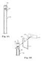
- FIG. 2Ashows a front view of the delivery device of FIG. 1 in a retracted state.
- FIG. 2Bshows a front view of the delivery device of FIG. 1 in an extended state.
- FIG. 2Cshows a perspective view of a portion of a control mechanism and release mechanism of FIG. 1 .
- FIG. 2Dshows a perspective view of the distal ends of the support member and release element shown in FIG. 1 .
- FIG. 3Ashows a front view of the release element in relation to the support member of FIG. 1 .
- FIG. 3Bshows the release element and support member of FIG. 3A in relation to a portion of the CSD shown in exploded detail.
- FIG. 4Ashows a front view of a delivery device according to another embodiment of the invention in a retracted state.
- FIG. 4Bshows a front view of the delivery device of FIG. 4A in an extended state.
- FIG. 4Cshows a side view of a portion of the control mechanism and release mechanism of FIG. 4A .
- FIG. 5Ashows a front view of a delivery device according to another embodiment of the invention in a retracted state.
- FIG. 5Bshows a front view of the delivery device of FIG. 5A in an extended state.
- FIG. 5Cshows a perspective view of a portion of the release mechanism of FIG. 5A .
- FIG. 5Dshows a cross sectional view of a portion of the control mechanism and release mechanism of FIG. 5A .
- FIG. 6Ashows a front view of a delivery device according to another embodiment of the invention in a retracted state.
- FIG. 6Bshows a front view of the delivery device of FIG. 6A in an extended state.
- FIG. 6Cshows a perspective view of a portion of the release mechanism of FIGS. 6A and 6B .
- FIG. 7Ashows a front view of a delivery device according to another embodiment of the invention in an extended state.
- FIG. 7Bshows a cross-sectional view of the delivery device of FIG. 7A taken along line 6 - 6 .
- FIG. 8Ashows a release element and support member according to another embodiment of the present invention coupled to a CSD.
- FIG. 8Bshows the release element and support member of FIG. 8A released from the CSD.
- FIG. 9Ashows a release element and support member according to another embodiment of the present invention coupled to a CSD.
- FIG. 9Bshows the release element and support member of FIG. 9A released from the CSD.
- FIG. 10Ashows a release element and support member according to another embodiment of the present invention coupled to a CSD.
- FIG. 10Bshows the release element and support member of FIG. 10A released from the CSD.
- FIG. 11Ashows a portion of a release mechanism according to another embodiment of the invention.
- FIG. 11Bshows the release mechanism of FIG. 11A coupled to a portion of a CSD.
- FIG. 11Cshows the release mechanism of FIG. 11B de-coupled from the CSD.
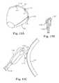
- FIG. 12Ashows a CSD having a release structure according to one embodiment of the invention.
- FIG. 12Bshows a release mechanism according to one embodiment of the present invention in relation to the CSD of FIG. 12A .
- FIG. 12Cshows a side-sectional view of the CSD of FIG. 12A coupled to the release mechanism.
- FIG. 13Ashows a CSD having a release structure according to yet another embodiment of the invention.
- FIG. 13Bshows the release structure of FIG. 13A and a release mechanism according to one embodiment of the invention.
- FIG. 13Cshows the actuation of the release mechanism within the release structure shown in FIG. 13A .
- FIG. 13Dshows the release mechanism de-coupled from the release structure of FIG. 13A .
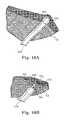
- FIG. 14Ashows a release structure and release mechanism according to another embodiment of the present invention.
- FIG. 14Bshows a front view of the release mechanism coupled to the release structure of FIG. 14A .
- FIG. 14Cshows a front view of the release mechanism de-coupled from the release structure shown in FIG. 14B .
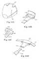
- FIG. 15Ashows a portion of a release mechanism releasably coupled to a CSD according to another embodiment of the invention.
- FIG. 15Bshows a side view of the release mechanism and CSD of FIG. 15A .
- FIG. 15Cshows a side view of the release mechanism of FIG. 15B released from the CSD.
- FIG. 16Ashows a release structure and release mechanism according to another embodiment of the present invention.
- FIG. 16Bshows a front view of the release mechanism coupled to the release structure of FIG. 16A .
- FIG. 16Cshows a front view of the release mechanism de-coupled from the release structure shown in FIG. 16B .
- FIG. 17shows a detailed and partially sectional view of a support member and release element in accordance with another embodiment of the invention, in an engaged state.
- FIG. 18shows a detailed view of a portion of the support member and release element shown in FIG. 17 , in a released state.
- FIG. 1illustrates a delivery device 100 according to one embodiment of the present invention supporting a cardiac support device (CSD) 104 for deployment over a patient's heart.
- the CSD 104may be any type of cardiac support device, including, without limitation, any of the devices disclosed in any of the patents and patent publications referenced and incorporated herein in the Background of the Invention.
- the CSD 104includes an open base end 108 and an apex portion 112 having an open apex end 116 .
- a hem 117is formed about the open base end 108 of the CSD 104 .
- the delivery device 100includes a body 120 , a deployment mechanism 124 , an actuator or a control mechanism 128 on the body 120 operatively coupled to the deployment mechanism 124 , and a release mechanism 132 (see FIG. 2C ) on the body 120 for releasably coupling the CSD 104 to the deployment mechanism 124 .
- the deployment mechanism 124is operable to move between a first retracted or closed state, as shown in FIG. 2A , and a second extended or open state, as shown in FIG. 1 .
- FIG. 2Bshows the deployment mechanism 124 moved to an extended but not opened state.
- the deployment mechanism 124is further adapted to releasably support the CSD 104 and to accurately position the CSD 104 at a desired implantation position on the patient's heart.
- the deployment mechanism 124includes at least one elongate support member 136 . In the illustrated embodiment, the deployment mechanism 124 includes eight support members 136 . The invention is not so limited, however, and the deployment mechanism 124 may include a greater or few number of support members 136 in varying configurations.
- the control mechanism 128drives the deployment mechanism 124 between the retracted and extended states for positioning the CSD 104 on the heart.
- the control mechanism 128is slidable along a portion of the length of the body 104 to move the support members 136 from the retracted state to the extended state.
- the support members 136are curved so that the support members 136 form a cup shape to receive the CSD 104 when in the extended state.
- the control mechanism 128also includes means for spreading apart or otherwise shaping the support members 136 when in the extended state.
- the release mechanism 132releasably couples the CSD 104 to the deployment mechanism 124 .
- the release mechanism 132is operated to release the CSD 104 from the delivery device 100 onto the heart.
- the release mechanism 132includes a release element 140 (see FIG. 2A ) for releasably engaging the CSD 104 and an actuator mechanism 144 operatively coupled to the release element 140 to control release of the CSD 104 from the release element 140 .
- the release element 140is an elongate member positioned adjacent to each of the support members 136 .
- a distal end 148 of the release element 140is movable from an engaged state in which the release element 140 permits the CSD 104 to be mounted to the deployment mechanism 124 and a released state in which the release element 140 releases the CSD 104 from the deployment mechanism 124 .
- An actuator mechanism 144is operable to move the release element 140 between the engaged and released states.
- the release elements 140slide through a channel 156 in the support members 136 .
- the support members 136are formed with a plurality of slots 158 to provide incremental advancement of the release elements 140 relative to the support members 136 .
- control mechanism 128 and the actuator mechanism 144are integrated into a cylinder 160 positioned about the body 120 .
- the cylinder 160slides over a first or main travel region T while moving the all of the support members 136 from the retracted state to the extended state.
- a second control mechanism 138 including a first user interface 164is provided for moving individual support members 136 from the retracted state to the extended state.
- the first user interfaces 164are individually slidable over a second or supplementary travel region t to move the support members 136 .
- the release elements 140remain in the engaged state while the support members 136 are moved from the retracted state to the extended state.
- the actuator mechanism 144is actuated by sliding a second user interface 168 coupled to the support elements 140 over a third or individual travel region I to move the release elements 140 between engaged and released states.
- the actuator mechanism 144is operable to actuate the release elements 140 individually. In other embodiments, however, two or more, or all, of the release elements 140 may be actuated as a group.
- the CSD 104includes a release structure 170 releasably engaged by one or both of the deployment mechanism 124 and the release element 140 .
- the release structure 170is adapted for coupling to the deployment mechanism 124 for facilitating release of the CSD 104 from the deployment mechanism 124 .
- some embodiments of the CSD 104includes a lubricious element 174 .
- Lubricious element 174can also be releasably coupled to the CSD 104 by the release mechanism 132 .
- the release mechanism 132is operable to de-couple at least a portion of the lubricious element 174 from the CSD 104 .
- FIG. 3Billustrates the release element 140 in more detail.
- the release element 140is in the form of a hook.
- a release structure 170 in the form of a loop of cord or sutureis coupled to the hem 117 of the CSD 104 .
- the release structure 170is coupled to the release element 140 through a hole 157 in the lubricious element 174 .
- the CSD 104is placed over a patient's heart with the device 100 as follows.
- the CSD 104is mounted to the deployment mechanism 124 with the release elements 140 in the engaged state.
- the deployment mechanism 124is put into the retracted state as shown in FIG. 2A .
- the delivery device body 120is manipulated to position the CSD 104 near the heart.
- the userslides the cylinder 160 distally over the body 120 , advancing the support members 136 from the retracted state to the extended state while the release elements 140 remain in the engaged state.
- the usermay actuate the first user interfaces 164 to move the support members 136 between the retracted and extended states individually to more precisely position the CSD 104 about the heart.
- the actuator mechanisms 144are actuated by sliding the second user interfaces 168 to move the release elements 140 from the engaged state to the released state to release the CSD 104 from the delivery device 100 .
- the release element 140is retracted within the channel 156 such that the release structure 170 coupled to the release element 140 .
- the release structure 170is released from the support member 136 .
- FIGS. 4A-4C, 5A-5D, 6A-6C and 7A-7Billustrate various additional embodiments of the control mechanism 128 and actuator mechanism 144 .
- FIGS. 8A-8B, 9A-9B, 10A-10B, 11A-11C, 12A-12C, 13A-13D and 14A-14Cillustrate various additional embodiments of the release element 140 and release stricture 170 .
- the various embodiments of the control mechanism 128 and actuator mechanism 140 described with respect to FIGS. 1, 2A-2D, 3A-3B, 4A-4C, 5A-5D, 6A-6C and 7A-7Bmay be used in an combination with the various embodiments of the release element 140 and release structure 170 described with respect to FIGS. a, 2 A- 2 D, 3 A- 3 B, 8 A- 8 B, 9 A- 9 B, 10 A- 10 B, 11 A- 11 C, 12 A- 12 C, 13 A- 13 D and 14 A- 14 C.
- FIGS. 4A-4Cillustrate a delivery device 200 according to another embodiment of the invention showing an alternate release mechanism.
- the delivery device 200includes a body 220 , a deployment mechanism 224 , a control mechanism 228 on the body 220 operatively coupled to the deployment mechanism 224 , and a release mechanism 232 on the body 220 for releasably coupling a CSD (not shown) to the deployment mechanism 224 .
- a CSDnot shown
- advancing a cylinder 260actuates the control mechanism 228 , moving the deployment mechanism 224 from a retracted state as shown in FIG. 4A to an extended state as shown in FIG. 4B .
- the control mechanism 228is further provided with a locking feature 274 for locking individual advancement of the support members 236 .
- the locking feature 274includes protrusions 278 and keyways 282 formed in the cylinder 260 . Rotation of the cylinder 260 , as indicated by arrow 284 , captures the protrusions 278 in the keyways 282 , preventing individual advancement of the support members 236 .
- the release mechanism 232includes a release element 240 and an actuator mechanism 244 .
- the actuator mechanism 244includes a tilting lever arm 286 coupled to a mechanical linkage 290 . Tilting the lever arm 286 forward, as indicated by arrow 292 , pulls the linkage 290 proximally to move the release elements 240 from an engaged state to a released state.
- the lever arm 286is also part of the control mechanism 228 and functions as a user interface for advancing the support members 236 individually.
- FIGS. 5A-5Dillustrate a delivery device 300 according to another embodiment of the invention showing an alternate release mechanism.
- the delivery device 300includes a body 320 , a deployment mechanism 324 , a control mechanism 328 on the body 320 operatively coupled to the deployment mechanism 324 , and a release mechanism 332 on the body 320 for releasably coupling a CSD (not shown) to the deployment mechanism 324 .
- advancing a cylinder 360actuates the control mechanism 328 , moving the deployment mechanism 324 from a retracted state as shown in FIG. 5A to an extended (but not opened) state as shown in FIG. 5B .
- the control mechanism 324further includes user interface buttons 364 for individually advancing the support members 336 and release elements 340 .
- the release mechanism 332includes a release element 340 and an actuator mechanism 344 .
- the actuator mechanism 344includes a rotating actuator cylinder 391 that is coupled to all of the release elements 340 .
- the actuator mechanism 344is operable to move all of the release elements 340 from an engaged state to a release state in unison upon rotation of the actuator cylinder 391 .
- the release elements 340each have an engagement pin 392 that is synchronized with axial teeth 393 in the actuator cylinder 391 . Rotational movement of the actuator cylinder 391 captures the engagement pins 392 at various positions of individual adjustment of the support members 336 .
- a keyway 394 in the cylinder 360controls rotation and forward movement of the actuator cylinder 391 .
- FIGS. 6A-6Cillustrate another embodiment of a delivery device 400 showing an alternative release mechanism.
- the delivery device 400includes a body 420 , a deployment mechanism 424 , a control mechanism 428 on the body 420 operatively coupled to the deployment mechanism 424 , and a release mechanism 432 on the body 420 for releasably coupling a CSD (not shown) to the deployment mechanism 424 .
- the release mechanism 432includes a release element 440 and an actuator mechanism 444 . Similar to previously described embodiments, advancing a cylinder 460 actuates the control mechanism 424 , moving the deployment mechanism 424 from a retracted state as shown in FIG. 6A to an extended state as shown in FIG. 6B .
- FIGS. 7A and 7Billustrate another embodiment of a delivery device 500 showing an alternative release mechanism.
- the delivery device 500includes a body 520 , a deployment mechanism 524 , a control mechanism 528 on the body 520 operatively coupled to the deployment mechanism 524 , and a release mechanism 532 on the body 520 for releasably coupling a CSD (not shown) to the deployment mechanism 524 .
- a suction cup 525 for releasably engaging a patient's heartis connected to a vacuum source (not shown) though tube 527 .
- Actuator mechanism 544is operated in a manner similar to that of the above-described embodiments to move the deployment mechanism 524 from a retracted position (not shown) to the extended and open position shown in FIGS. 7A and 7B .
- the support members 536can be formed resilient members, and can be guided at least in part from their retracted positions to the extended and open positions shown in FIGS. 7A and 7B by the suction cup 525 .
- FIGS. 8A and 8Billustrate a support member 736 , release element 740 and release structure 770 according to another embodiment of the invention.
- the release element 740includes an opening 741 .
- the release structure 770is in the form of a loop of cord or suture that is threaded through a portion of the CSD 104 , with a first end 771 coupled to the delivery device 100 and a second end 772 that is free.
- the release element 740is in the engaged state, as shown in FIG. 8A , the free end 772 of the release structure 770 is inserted through the hole 741 and the release element 740 is retracted within the support member 736 .
- the free end 772 of the release structure 770is thus captured between the release element 740 and the support member 736 , coupling the CSD 104 to the support member 736 .
- the release element 740is moved to the released state, shown in FIG. 8B , the release element 740 is advanced distally relative to the support member 736 , releasing the release structure 770 .
- the release structure 770is easily pulled through the hole 741 and the CSD 104 as the support member 736 is withdrawn.
- FIGS. 9A and 9Billustrate a release element 840 and release structure 870 according to another embodiment of the present invention.
- the release element 840is in the form of a hook.
- the release structure 870is in the form of a loop of cord or suture having ends 871 , 872 coupled to the CSD 104 .
- the release structure 870is captured by the hook of the release element 840 and coupled to the support member 836 when the release element 840 is in the engaged state, as shown in FIG. 9A .
- the release structure 870is released to de-couple the support member 836 and the CSD 104 .
- FIGS. 10A and 10Billustrate a release element 940 and release structure 970 according to another embodiment of the present invention.
- the release element 940is in the form of a pair of pincers 943
- the release structure 970is in the form of a loop of cord or suture having a portion 773 coupled to the CSD 104 .
- the release element 932is in the engaged state, the release element 932 is retracted within the support member 936 , causing the pincers 943 to be pinched together, thus capturing the release structure 970 , as shown in FIG. 10A .
- the release element 940is moved to the released state, as shown in FIG. 10B , the release structure 970 is advanced distally relative to the support member 936 and the pincers 943 spread apart to release the release structure 970 .
- FIGS. 11A-11Cillustrate a support member 1036 , release element 1040 and release structure 1070 configuration according to another embodiment of the present invention.
- the release element 1040is in the form of a flat rod received within a channel 1056 formed by the support member 1036 .
- a distal end of the support member 1036includes an opening 1037 .
- the release structure 1070is in the form of a flexible band formed around at least a portion of the CSD 104 .
- the release structure 1070In the engaged state, the release structure 1070 is received in the opening 1037 and held in place by the release element 1040 which is positioned at the opening 1037 (see FIG. 11B ).
- the release element 1040is moved proximally within the channel 1057 to release the release structure 1070 from the support member 1036 .
- FIGS. 12A-12Cillustrate a support member 1136 , release element 1140 and release structure 1170 according to another embodiment of the invention.
- the release structure 1170is in the form of protrusions on the hem 117 of the CSD 104 and each has an opening 1171 therethrough (see FIG. 12A ).
- the support member 1136has a distal recess 1137 sized and shaped to receive the release structure 1170 .
- the release element 1140is in the form of a slender rod sized to be received in the opening 1171 .
- FIG. 12A-12Cillustrate a support member 1136 , release element 1140 and release structure 1170 according to another embodiment of the invention.
- the release structure 1170is in the form of protrusions on the hem 117 of the CSD 104 and each has an opening 1171 therethrough (see FIG. 12A ).
- the support member 1136has a distal recess 1137 sized and shaped to receive the release structure 1170 .
- the release structures 1170are positioned within the recesses 1137 and the release elements 1140 are inserted into the openings 1171 to hold the release structures 1170 in place.
- the release element 1140is withdrawn proximally out of the opening 1171 to release the release structure 1170 from the recesses 1137 .
- FIGS. 13A-Dillustrate a release element 1240 , support member 1236 and release structure 1270 according to another embodiment of the invention.
- the release structure 1270is in the form of a lock housing positioned on the hem 117 of the CSD 104 .
- a hook 1272is formed within the release structure 1270 .
- the release structure 1270further has a passageway 1271 for receiving the release element 1240 .
- the release element 1240In the engaged state, shown in FIG. 13B (release structure shown opened for clarity), the release element 1240 is captured on the hook 1272 .
- the release element 1240Upon movement of the release element 1240 from the engaged state, shown in solid lines in FIG. 13C , to a release state, shown in dashed lines, the release element 1240 disengages from the hook 1272 , allowing the release element 1240 to be withdrawn proximally through the passageway 1271 (see FIG. 13D ).
- FIGS. 14A-14Cillustrate a release element 1340 , support member 1336 and release structure 1370 according to another embodiment of the invention.
- the support member 1336includes a U-shaped yoke 1338 defining an opening 1339 .
- the release element 1340is movable from an engaged state, in which the release element 1340 is proximal to the opening 1339 (see FIG. 14B ), to a release state, in which the release element 1340 is positioned within the opening 1339 (see FIG. 14C ).
- the release structure 1370is in the form of a projection sized and shaped to be snugly received within the yoke 1338 . Movement of the release element 1340 from the engaged state, shown in FIG. 14B , to the release state, shown in FIG. 14C , ejects the release structure 1370 from the yoke 1338 .
- FIGS. 15A-15Cillustrate a portion of a release element 1440 , support member 1436 and release structure 1470 according to another embodiment of the invention.
- the release structure 1470is in the form of a length of cord or suture that is threaded through the CSD 104 .
- the support member 1436includes a pair of distal openings 1437 divided by a support bridge 1438 .
- the release element 1440includes a cutting surface 1441 .
- the release element 1440In the engaged state, shown in FIGS. 15A and 15B , the release element 1440 is positioned proximally to the openings 1437 .
- the release structure 1470is threaded through the openings 1437 and tied over the bridge 1438 to couple the CSD 104 to the support member 1436 .
- the release element 1440Upon movement of the release element 1440 to the release state, shown in FIG. 15C , the release element 1440 is moved distally over the release structure 1470 to cut the release structure 1470 , thus releasing
- FIGS. 16A-16Cillustrate a support member 1336 ′ and release structure 1370 ′ according to another embodiment of the invention.
- the support member 1336 ′ and release structure 1370 ′can be substantially the same or similar to support member 1336 and release structure 1370 described above in connection with FIGS. 14A-14C , and similar features are identified by similar reference numbers.
- the embodiment shown in FIGS. 16A-16Cdoes not include a release element 1340 .
- support member 1336 ′is passively disengaged from the release structure 1370 ′.
- the support member 1336 ′includes a C- or U-shaped yoke 1338 ′ defining an opening 1339 ′.
- the release structure 1370 ′is in the form of a projection sized and shaped to be snugly received within the yoke 1338 ′.
- Yoke 1338 ′is formed of resilient material that enables the yoke to sufficiently deform and “snap” onto the release structure 1370 ′ (e.g., to diametrically expand and then return to its original shape).
- the characteristics of the yoke 1338 ′ in cooperation with the release structure 1370 ′provides sufficient strength to enable the yoke to remain attached to the release structure while CSD 104 is positioned on the patient's heart.
- FIGS. 17 and 18illustrate a support member 1536 and release element 1540 according to another embodiment of the invention.
- the support member 1536is a tubular structure having an opening 1556 on its distal end.
- the release element 1540is an elongate member movable within the support member 1536 between retracted and extended positions.
- a finger on the distal end 1548 of the release element 1540has a tang 1551 and an inner element 1553 that cooperate to provide a functional engagement portion.
- the distal end 1548is formed with the tang 1551 and inner element 1553 separated and spaced from one another when the release element 1540 is in its released state shown in FIG. 18 with the distal end 1548 extending from the opening 1556 of the support member 1536 .
- the tang 1551is formed of flexible and resilient material, enabling the tang to be deformed from its free or native state into the hook shape of the capture position shown in FIG. 17 .
- release element 1540is in the engaged state shown in FIG. 17 , the tang 1551 is retained in the capture position adjacent to inner element 1553 .
- the tang 1551 of release element 1540can engage a release structure such a suture loop (not shown) on a CSD (also not shown) when the release element is in the engaged state. When moved to the released state shown in FIG. 18 , the tang 1551 will return to its native state to release the release structure. Locating the tang 1551 and inner element 1553 at the opening 1556 on the distal end of the support member 1536 can enhance the accuracy by which the CSD can be positioning on the patient's heart.
Landscapes
- Health & Medical Sciences (AREA)
- Cardiology (AREA)
- Oral & Maxillofacial Surgery (AREA)
- Transplantation (AREA)
- Engineering & Computer Science (AREA)
- Biomedical Technology (AREA)
- Heart & Thoracic Surgery (AREA)
- Vascular Medicine (AREA)
- Life Sciences & Earth Sciences (AREA)
- Animal Behavior & Ethology (AREA)
- General Health & Medical Sciences (AREA)
- Public Health (AREA)
- Veterinary Medicine (AREA)
- Surgical Instruments (AREA)
- Prostheses (AREA)
Abstract
Description
Claims (11)
Priority Applications (2)
| Application Number | Priority Date | Filing Date | Title |
|---|---|---|---|
| US14/086,804US9737404B2 (en) | 2006-07-17 | 2013-11-21 | Cardiac support device delivery tool with release mechanism |
| US15/682,111US10307252B2 (en) | 2006-07-17 | 2017-08-21 | Cardiac support device delivery tool with release mechanism |
Applications Claiming Priority (4)
| Application Number | Priority Date | Filing Date | Title |
|---|---|---|---|
| US11/487,953US7651462B2 (en) | 2006-07-17 | 2006-07-17 | Cardiac support device delivery tool with release mechanism |
| US12/638,059US8202212B2 (en) | 2006-07-17 | 2009-12-15 | Cardiac support device delivery tool with release mechanism |
| US13/524,093US8617051B2 (en) | 2006-07-17 | 2012-06-15 | Cardiac support device delivery tool with release mechanism |
| US14/086,804US9737404B2 (en) | 2006-07-17 | 2013-11-21 | Cardiac support device delivery tool with release mechanism |
Related Parent Applications (1)
| Application Number | Title | Priority Date | Filing Date |
|---|---|---|---|
| US13/524,093ContinuationUS8617051B2 (en) | 2006-07-17 | 2012-06-15 | Cardiac support device delivery tool with release mechanism |
Related Child Applications (1)
| Application Number | Title | Priority Date | Filing Date |
|---|---|---|---|
| US15/682,111ContinuationUS10307252B2 (en) | 2006-07-17 | 2017-08-21 | Cardiac support device delivery tool with release mechanism |
Publications (2)
| Publication Number | Publication Date |
|---|---|
| US20140081077A1 US20140081077A1 (en) | 2014-03-20 |
| US9737404B2true US9737404B2 (en) | 2017-08-22 |
Family
ID=38957551
Family Applications (5)
| Application Number | Title | Priority Date | Filing Date |
|---|---|---|---|
| US11/487,953Active2027-10-20US7651462B2 (en) | 2006-07-17 | 2006-07-17 | Cardiac support device delivery tool with release mechanism |
| US12/638,059Expired - Fee RelatedUS8202212B2 (en) | 2006-07-17 | 2009-12-15 | Cardiac support device delivery tool with release mechanism |
| US13/524,093ActiveUS8617051B2 (en) | 2006-07-17 | 2012-06-15 | Cardiac support device delivery tool with release mechanism |
| US14/086,804Expired - Fee RelatedUS9737404B2 (en) | 2006-07-17 | 2013-11-21 | Cardiac support device delivery tool with release mechanism |
| US15/682,111ActiveUS10307252B2 (en) | 2006-07-17 | 2017-08-21 | Cardiac support device delivery tool with release mechanism |
Family Applications Before (3)
| Application Number | Title | Priority Date | Filing Date |
|---|---|---|---|
| US11/487,953Active2027-10-20US7651462B2 (en) | 2006-07-17 | 2006-07-17 | Cardiac support device delivery tool with release mechanism |
| US12/638,059Expired - Fee RelatedUS8202212B2 (en) | 2006-07-17 | 2009-12-15 | Cardiac support device delivery tool with release mechanism |
| US13/524,093ActiveUS8617051B2 (en) | 2006-07-17 | 2012-06-15 | Cardiac support device delivery tool with release mechanism |
Family Applications After (1)
| Application Number | Title | Priority Date | Filing Date |
|---|---|---|---|
| US15/682,111ActiveUS10307252B2 (en) | 2006-07-17 | 2017-08-21 | Cardiac support device delivery tool with release mechanism |
Country Status (2)
| Country | Link |
|---|---|
| US (5) | US7651462B2 (en) |
| WO (1) | WO2008011411A2 (en) |
Cited By (1)
| Publication number | Priority date | Publication date | Assignee | Title |
|---|---|---|---|---|
| US20170348103A1 (en)* | 2006-07-17 | 2017-12-07 | Mardil, Inc. | Cardiac Support Device Delivery Tool with Release Mechanism |
Families Citing this family (12)
| Publication number | Priority date | Publication date | Assignee | Title |
|---|---|---|---|---|
| JP4083683B2 (en) | 2001-09-07 | 2008-04-30 | マーディル, インコーポレイテッド | Method and apparatus for external heart fixation |
| US20070208217A1 (en) | 2006-03-03 | 2007-09-06 | Acorn Cardiovascular, Inc. | Self-adjusting attachment structure for a cardiac support device |
| US20080004488A1 (en)* | 2006-06-29 | 2008-01-03 | Acorn Cardiovascular, Inc. | Low friction delivery tool for a cardiac support device |
| EP2410912B1 (en) | 2009-03-27 | 2020-02-12 | Mardil, Inc. | Intra-operative heart size measuring tool |
| US20120059457A1 (en)* | 2010-09-02 | 2012-03-08 | Leinsing Karl R | Minimally invasive surgical instrument for delivery of cardiac devices |
| DE102012108025A1 (en)* | 2012-08-30 | 2014-03-06 | Aesculap Ag | Surgical implant has deformable support element with support surface for surface of implant to create tissue structure of patient, where support element is connected with dimensionally stable holding unit |
| DE102012108026A1 (en) | 2012-08-30 | 2014-03-06 | Aesculap Ag | Surgical apparatus for placing implants on heart, has positioning device that is arranged for positioning of two implants at predetermined positions on the heart |
| AU2013328871B2 (en)* | 2012-10-12 | 2018-08-16 | Diaxamed, Llc | Cardiac treatment system and method |
| USD717954S1 (en) | 2013-10-14 | 2014-11-18 | Mardil, Inc. | Heart treatment device |
| WO2017091812A1 (en) | 2015-11-25 | 2017-06-01 | Talon Medical, LLC | Tissue engagement devices, systems, and methods |
| WO2018039403A1 (en)* | 2016-08-24 | 2018-03-01 | Terumo Cardiovascular Systems Corporation | Heart rotator |
| KR20220035405A (en)* | 2019-07-09 | 2022-03-22 | 엘릭서 메디컬 코포레이션 | Methods and devices for delivering implantable prostheses |
Citations (166)
| Publication number | Priority date | Publication date | Assignee | Title |
|---|---|---|---|---|
| DE324524C (en) | 1919-06-13 | 1920-08-31 | Siemens Schuckertwerke G M B H | Device for generating blood congestion |
| US1682119A (en) | 1928-08-28 | Cleaning device | ||
| US1965542A (en) | 1933-11-24 | 1934-07-03 | Jr William Colvin | Fabric |
| US1982207A (en) | 1933-12-29 | 1934-11-27 | Henry D Furniss | Clamping instrument and process of using the same |
| US2138603A (en) | 1936-10-06 | 1938-11-29 | Du Pont | Explosive package |
| US2278926A (en) | 1941-02-15 | 1942-04-07 | Metal Textile Corp | Knitted metallic fabric for belting and other uses |
| US2376442A (en) | 1943-07-07 | 1945-05-22 | Mehler Hugo | Tubular netting |
| US2992550A (en) | 1959-05-13 | 1961-07-18 | Hagin Frith & Sons | Knitted mesh |
| US3384530A (en) | 1964-07-31 | 1968-05-21 | Plastic Textile Access Ltd | Extruded plastic net, method of making the same and sack made of said net |
| US3452742A (en) | 1966-05-31 | 1969-07-01 | Us Catheter & Instr Corp | Controlled vascular curvable spring guide |
| US3551543A (en) | 1967-09-06 | 1970-12-29 | Plastic Textile Access Ltd | Manufacture of plastic net |
| US3587567A (en) | 1968-12-20 | 1971-06-28 | Peter Paul Schiff | Mechanical ventricular assistance assembly |
| US3732662A (en) | 1971-07-30 | 1973-05-15 | F Paxton | Method of forming, filling, closing and labelling tubular netting bags |
| US3768643A (en) | 1971-07-27 | 1973-10-30 | Manetti M | Nestable net produce bag and carrier therefor |
| US3983863A (en) | 1975-06-02 | 1976-10-05 | American Hospital Supply Corporation | Heart support for coronary artery surgery |
| US4048990A (en) | 1976-09-17 | 1977-09-20 | Goetz Robert H | Heart massage apparatus |
| US4196534A (en) | 1977-10-27 | 1980-04-08 | Toshitsune Shibamoto | Plastic net bag and label |
| SU1009457A1 (en) | 1981-07-15 | 1983-04-07 | Проблемная Лаборатория "Вспомогательного Кровообращения" Благовещенского Медицинского Института | Artificial pericardium |
| US4403604A (en) | 1982-05-13 | 1983-09-13 | Wilkinson Lawrence H | Gastric pouch |
| US4428375A (en) | 1982-02-16 | 1984-01-31 | Ellman Barry R | Surgical bag for splenorrhaphy |
| US4466331A (en) | 1983-06-06 | 1984-08-21 | Redden Net Co., Inc. | Method of forming twisted multiple strand synthetic twine, twines produced thereby, and fishnets formed thereof |
| US4536893A (en) | 1982-03-03 | 1985-08-27 | Roberto Parravicini | Implant device for substaining the activity of the myocardium |
| JPS60203250A (en) | 1984-03-29 | 1985-10-14 | 日本ゼオン株式会社 | heart surgery patch |
| US4567900A (en) | 1984-06-04 | 1986-02-04 | Moore J Paul | Internal deployable defibrillator electrode |
| US4598039A (en) | 1984-07-02 | 1986-07-01 | At&T Bell Laboratories | Formation of features in optical material |
| US4630597A (en) | 1984-04-30 | 1986-12-23 | Adrian Kantrowitz | Dynamic aortic patch for thoracic or abdominal implantation |
| US4637377A (en) | 1985-09-20 | 1987-01-20 | Loop Floyd D | Pillow or support member for surgical use |
| US4690134A (en) | 1985-07-01 | 1987-09-01 | Snyders Robert V | Ventricular assist device |
| EP0280564A2 (en) | 1987-02-27 | 1988-08-31 | Intermedics, Inc. | Implantable defribrillation electrodes |
| US4790850A (en) | 1986-03-14 | 1988-12-13 | Richards Medical Company | Phosthetic ligament |
| EP0303719A1 (en) | 1987-02-23 | 1989-02-22 | Blagoveschensky Gosudarstvenny Meditsinsky Institut | Artificial pericardium |
| DE3831540A1 (en) | 1987-09-16 | 1989-04-06 | Phillip H Evans | VENTILATION DEVICE FOR CARDIOVASCULAR PUMPS |
| US4821723A (en) | 1987-02-27 | 1989-04-18 | Intermedics Inc. | Biphasic waveforms for defibrillation |
| US4840626A (en) | 1986-09-29 | 1989-06-20 | Johnson & Johnson Patient Care, Inc. | Heparin-containing adhesion prevention barrier and process |
| US4878890A (en) | 1986-10-15 | 1989-11-07 | Ethicon, Inc. | Perihepatic prosthesis |
| US4957477A (en) | 1986-05-22 | 1990-09-18 | Astra Tech Ab | Heart assist jacket and method of using it |
| JPH02271829A (en) | 1989-04-13 | 1990-11-06 | Tanaka Kikinzoku Kogyo Kk | Electrode for determining myocardial infarction |
| US4973300A (en) | 1989-09-22 | 1990-11-27 | Pioneering Technologies, Inc. | Cardiac sling for circumflex coronary artery surgery |
| US4976730A (en) | 1988-10-11 | 1990-12-11 | Kwan Gett Clifford S | Artificial pericardium |
| US4995857A (en) | 1989-04-07 | 1991-02-26 | Arnold John R | Left ventricular assist device and method for temporary and permanent procedures |
| US5042463A (en) | 1990-05-23 | 1991-08-27 | Siemens-Pacesetter, Inc. | Patch electrode for heart defibrillator |
| US5057117A (en) | 1989-04-27 | 1991-10-15 | The Research Foundation Of State University Of New York | Method and apparatus for hemostasis and compartmentalization of a bleeding internal bodily organ |
| US5074129A (en) | 1989-12-26 | 1991-12-24 | Novtex | Formable fabric |
| US5087243A (en) | 1990-06-18 | 1992-02-11 | Boaz Avitall | Myocardial iontophoresis |
| US5131905A (en) | 1990-07-16 | 1992-07-21 | Grooters Ronald K | External cardiac assist device |
| US5150706A (en) | 1991-08-15 | 1992-09-29 | Cox James L | Cooling net for cardiac or transplant surgery |
| US5186711A (en) | 1989-03-07 | 1993-02-16 | Albert Einstein College Of Medicine Of Yeshiva University | Hemostasis apparatus and method |
| US5188813A (en) | 1988-10-12 | 1993-02-23 | Johnson Matthey Public Limited Company | Metal fabrics |
| WO1993003685A1 (en) | 1991-08-19 | 1993-03-04 | Mark Allen Eberbach | Surgical apparatus and method |
| US5192314A (en) | 1991-12-12 | 1993-03-09 | Daskalakis Michael K | Synthetic intraventricular implants and method of inserting |
| US5207725A (en) | 1991-03-05 | 1993-05-04 | Pinkerton Linda L | Soap holder |
| US5224363A (en) | 1988-12-16 | 1993-07-06 | Golden Needles Knitting & Glove Co., Inc. | Method of making garment, garment, and strand material |
| EP0557964A1 (en) | 1992-02-24 | 1993-09-01 | United States Surgical Corporation | Articulating mesh deployment apparatus |
| US5256132A (en) | 1992-08-17 | 1993-10-26 | Snyders Robert V | Cardiac assist envelope for endoscopic application |
| US5279539A (en) | 1992-08-17 | 1994-01-18 | Ethicon, Inc. | Drawstring surgical pouch and method of use for preventing ovarian adhesions |
| US5290217A (en) | 1991-10-10 | 1994-03-01 | Earl K. Sipes | Method and apparatus for hernia repair |
| US5336253A (en) | 1993-02-23 | 1994-08-09 | Medtronic, Inc. | Pacing and cardioversion lead systems with shared lead conductors |
| US5339657A (en) | 1992-09-01 | 1994-08-23 | Mcmurray Fabrics, Inc. | Net having different size openings and method of making |
| US5341815A (en) | 1993-03-25 | 1994-08-30 | Ethicon, Inc. | Endoscopic surgical pouch |
| US5356432A (en) | 1993-02-05 | 1994-10-18 | C. R. Bard, Inc. | Implantable mesh prosthesis and method for repairing muscle or tissue wall defects |
| US5366460A (en) | 1990-10-11 | 1994-11-22 | Cook Incorporated | Apparatus and method for laparoscope hernia repair |
| US5383840A (en) | 1992-07-28 | 1995-01-24 | Vascor, Inc. | Biocompatible ventricular assist and arrhythmia control device including cardiac compression band-stay-pad assembly |
| US5385156A (en) | 1993-08-27 | 1995-01-31 | Rose Health Care Systems | Diagnostic and treatment method for cardiac rupture and apparatus for performing the same |
| US5405360A (en) | 1992-02-24 | 1995-04-11 | United States Surgical Corporation | Resilient arm mesh deployer |
| US5409703A (en) | 1993-06-24 | 1995-04-25 | Carrington Laboratories, Inc. | Dried hydrogel from hydrophilic-hygroscopic polymer |
| US5429584A (en) | 1990-11-09 | 1995-07-04 | Mcgill University | Cardiac assist method and apparatus |
| DE29517393U1 (en) | 1995-11-03 | 1996-02-01 | Hohmann, Claas, Dr.med., 78315 Radolfzell | Pericardial prosthesis |
| US5507779A (en) | 1994-04-12 | 1996-04-16 | Ventritex, Inc. | Cardiac insulation for defibrillation |
| WO1996016601A1 (en) | 1994-11-30 | 1996-06-06 | W.L. Gore & Associates, Inc. | Surgical device for protecting organs from formation of adhesions |
| US5524633A (en) | 1991-11-25 | 1996-06-11 | Advanced Surgical, Inc. | Self-deploying isolation bag |
| US5533958A (en) | 1993-06-17 | 1996-07-09 | Wilk; Peter J. | Intrapericardial assist device and associated method |
| WO1996031175A1 (en) | 1995-04-01 | 1996-10-10 | Smith & Nephew Plc | Fabric article with extension indicator |
| US5593441A (en) | 1992-03-04 | 1997-01-14 | C. R. Bard, Inc. | Method for limiting the incidence of postoperative adhesions |
| US5603337A (en) | 1994-12-05 | 1997-02-18 | Jarvik; Robert | Two-stage cardiomyoplasty |
| US5611515A (en) | 1991-12-03 | 1997-03-18 | Boston Scientic Corporation | Bladder neck suspension procedure |
| US5634931A (en) | 1994-09-29 | 1997-06-03 | Surgical Sense, Inc. | Hernia mesh patches and methods of their use |
| US5647380A (en) | 1995-06-07 | 1997-07-15 | W. L. Gore & Associates, Inc. | Method of making a left ventricular assist device |
| US5695525A (en) | 1992-05-20 | 1997-12-09 | C.R. Bard, Incorporated | Implantable prosthesis and method and apparatus for loading and delivering an implantable prosthesis |
| US5702343A (en) | 1996-10-02 | 1997-12-30 | Acorn Medical, Inc. | Cardiac reinforcement device |
| US5713954A (en) | 1995-06-13 | 1998-02-03 | Abiomed R&D, Inc. | Extra cardiac ventricular assist device |
| US5735290A (en) | 1993-02-22 | 1998-04-07 | Heartport, Inc. | Methods and systems for performing thoracoscopic coronary bypass and other procedures |
| US5766216A (en) | 1996-05-30 | 1998-06-16 | Gangal; Hanamraddi T. | Band applicator for appendicular and meso-appendicular stumps |
| WO1998029041A1 (en) | 1997-01-02 | 1998-07-09 | Myocor, Inc. | Heart wall tension reduction apparatus and method |
| US5782746A (en) | 1996-02-15 | 1998-07-21 | Wright; John T. M. | Local cardiac immobilization surgical device |
| WO1998035632A1 (en) | 1997-02-13 | 1998-08-20 | Boston Scientific Ireland Limited | Stabilization sling for use in minimally invasive pelvic surgery |
| US5800334A (en) | 1993-06-17 | 1998-09-01 | Wilk; Peter J. | Intrapericardial assist device and associated method |
| US5800528A (en) | 1995-06-13 | 1998-09-01 | Abiomed R & D, Inc. | Passive girdle for heart ventricle for therapeutic aid to patients having ventricular dilatation |
| US5839842A (en) | 1998-02-05 | 1998-11-24 | Lever Brothers Company, Division Of Conopco, Inc. | Cleansing system including a toilet bar and sponge supported within a porous pouch |
| US5853422A (en) | 1996-03-22 | 1998-12-29 | Scimed Life Systems, Inc. | Apparatus and method for closing a septal defect |
| WO1998058598A1 (en) | 1997-06-21 | 1998-12-30 | Hans Haindl | Bag for at least partially enveloping a heart |
| US5928250A (en) | 1997-01-30 | 1999-07-27 | Nissho Corporation | Catheter assembly for intracardiac suture |
| US5931810A (en) | 1996-12-05 | 1999-08-03 | Comedicus Incorporated | Method for accessing the pericardial space |
| WO1999044534A1 (en) | 1998-03-05 | 1999-09-10 | The University Of Cincinnati | Device and method for restructuring heart chamber geometry |
| US5961440A (en) | 1997-01-02 | 1999-10-05 | Myocor, Inc. | Heart wall tension reduction apparatus and method |
| US5972013A (en) | 1997-09-19 | 1999-10-26 | Comedicus Incorporated | Direct pericardial access device with deflecting mechanism and method |
| US5984932A (en) | 1996-11-27 | 1999-11-16 | Yoon; Inbae | Suturing instrument with one or more spreadable needle holders mounted for arcuate movement |
| US5990378A (en) | 1995-05-25 | 1999-11-23 | Bridport Gundry (Uk) Limited | Textile surgical implants |
| WO2000001306A1 (en) | 1998-07-07 | 2000-01-13 | Pulsecare Ltd. | Minimal invasive cardiac massage device |
| WO2000002500A1 (en) | 1998-07-13 | 2000-01-20 | Acorn Cardiovascular, Inc. | Cardiac disease treatment device and method |
| WO2000006026A2 (en) | 1998-07-29 | 2000-02-10 | Myocor, Inc. | Heart wall tension reduction apparatus and method |
| WO2000006027A2 (en) | 1998-07-29 | 2000-02-10 | Myocor, Inc. | Heart stress reduction apparatus and method |
| WO2000006028A1 (en) | 1998-07-29 | 2000-02-10 | Myocor, Inc. | Transventricular implant tools and devices |
| WO2000016700A1 (en) | 1998-09-21 | 2000-03-30 | Myocor, Inc. | External stress reduction device and method |
| US6076013A (en) | 1999-01-14 | 2000-06-13 | Brennan; Edward F. | Apparatus and methods for treating congestive heart failure |
| US6085754A (en) | 1998-07-13 | 2000-07-11 | Acorn Cardiovascular, Inc. | Cardiac disease treatment method |
| US6089051A (en) | 1993-01-14 | 2000-07-18 | W.C. Heraeus Gmbh | Warp-knit fabric of noble metal-containing wires, and method for the production thereof |
| US6095968A (en) | 1998-04-10 | 2000-08-01 | Cardio Technologies, Inc. | Reinforcement device |
| US6123662A (en) | 1998-07-13 | 2000-09-26 | Acorn Cardiovascular, Inc. | Cardiac disease treatment and device |
| US6155972A (en) | 1999-02-02 | 2000-12-05 | Acorn Cardiovascular, Inc. | Cardiac constraint jacket construction |
| US6155968A (en) | 1998-07-23 | 2000-12-05 | Wilk; Peter J. | Method and device for improving cardiac function |
| US6169922B1 (en) | 1998-11-18 | 2001-01-02 | Acorn Cardiovascular, Inc. | Defibrillating cardiac jacket with interwoven electrode grids |
| WO2001002500A1 (en) | 1999-06-30 | 2001-01-11 | Basf Coatings Ag | Coating material and its use for producing filler coats and stone impact protection primers |
| US6174279B1 (en) | 1999-09-21 | 2001-01-16 | Acorn Cardiovascular, Inc. | Cardiac constraint with tension indicator |
| US6179791B1 (en) | 1999-09-21 | 2001-01-30 | Acorn Cardiovascular, Inc. | Device for heart measurement |
| US6193648B1 (en) | 1999-09-21 | 2001-02-27 | Acorn Cardiovascular, Inc. | Cardiac constraint with draw string tensioning |
| US6205747B1 (en) | 1997-02-07 | 2001-03-27 | Rosalina Paniagua Olaechea | Process for closing nets for fruits and the like and net closed by means of said process |
| US6206004B1 (en) | 1996-12-06 | 2001-03-27 | Comedicus Incorporated | Treatment method via the pericardial space |
| US6230714B1 (en) | 1998-11-18 | 2001-05-15 | Acorn Cardiovascular, Inc. | Cardiac constraint with prior venus occlusion methods |
| US6241654B1 (en) | 1999-07-07 | 2001-06-05 | Acorn Cardiovasculr, Inc. | Cardiac reinforcement devices and methods |
| WO2001067985A1 (en) | 2000-03-10 | 2001-09-20 | Paracor Surgical, Inc. | Expandable cardiac harness for treating congestive heart failure |
| US6293906B1 (en) | 2000-01-14 | 2001-09-25 | Acorn Cardiovascular, Inc. | Delivery of cardiac constraint jacket |
| US6360749B1 (en) | 1998-10-09 | 2002-03-26 | Swaminathan Jayaraman | Modification of properties and geometry of heart tissue to influence heart function |
| US20020072662A1 (en) | 1998-09-11 | 2002-06-13 | Hall Andrew F. | Magnetically navigable telescoping catheter and method of navigating telescoping catheter |
| US6425856B1 (en) | 2000-05-10 | 2002-07-30 | Acorn Cardiovascular, Inc. | Cardiac disease treatment and device |
| US6432039B1 (en) | 1998-12-21 | 2002-08-13 | Corset, Inc. | Methods and apparatus for reinforcement of the heart ventricles |
| US6482146B1 (en) | 2000-06-13 | 2002-11-19 | Acorn Cardiovascular, Inc. | Cardiac disease treatment and device |
| US6517570B1 (en) | 1994-08-31 | 2003-02-11 | Gore Enterprise Holdings, Inc. | Exterior supported self-expanding stent-graft |
| US6541678B2 (en) | 1999-09-27 | 2003-04-01 | Brennen Medical, Inc. | Immunostimulating coating for surgical devices |
| US6564094B2 (en) | 2000-12-22 | 2003-05-13 | Acorn Cardiovascular, Inc. | Cardiac disease treatment and device |
| US6569082B1 (en) | 1999-08-10 | 2003-05-27 | Origin Medsystems, Inc. | Apparatus and methods for cardiac restraint |
| US6572533B1 (en) | 2000-08-17 | 2003-06-03 | Acorn Cardiovascular, Inc. | Cardiac disease treatment and device |
| US6587734B2 (en) | 1998-11-04 | 2003-07-01 | Acorn Cardiovascular, Inc. | Cardio therapeutic heart sack |
| US6612978B2 (en) | 1999-12-22 | 2003-09-02 | Paracor Surgical, Inc. | Expandable cardiac harness for treating congestive heart failure |
| US6620095B2 (en) | 2000-12-22 | 2003-09-16 | Syde A. Taheri | Cradle-assisted myocardial repair and treatment |
| US20030208220A1 (en) | 2002-05-06 | 2003-11-06 | Worley Seth J. | Telescopic, peel-away introducer and method of using the same |
| US20030229265A1 (en) | 2000-06-13 | 2003-12-11 | Girard Michael J. | Cardiac support device |
| US6673009B1 (en) | 2000-11-08 | 2004-01-06 | Acorn Cardiovascular, Inc. | Adjustment clamp |
| US6682475B2 (en) | 2002-06-11 | 2004-01-27 | Acorn Cardiovascular, Inc. | Tension indicator for cardiac support device and method therefore |
| US6695769B2 (en) | 2001-09-25 | 2004-02-24 | The Foundry, Inc. | Passive ventricular support devices and methods of using them |
| US6723041B2 (en) | 2001-09-10 | 2004-04-20 | Lilip Lau | Device for treating heart failure |
| US6730016B1 (en) | 2000-06-12 | 2004-05-04 | Acorn Cardiovascular, Inc. | Cardiac disease treatment and device |
| US6755779B2 (en) | 2000-12-01 | 2004-06-29 | Acorn Cardiovascular, Inc. | Apparatus and method for delivery of cardiac constraint jacket |
| US20040138521A1 (en) | 2003-01-10 | 2004-07-15 | Grabek James R. | Myocardial constraint |
| US20040210104A1 (en)* | 2002-11-15 | 2004-10-21 | Lilip Lau | Cardiac harness delivery device and method |
| US20050033109A1 (en) | 2001-10-31 | 2005-02-10 | Lilip Lau | Heart failure treatment device and method |
| US20050059855A1 (en) | 2002-11-15 | 2005-03-17 | Lilip Lau | Cardiac harness delivery device and method |
| US20050059854A1 (en) | 2003-09-16 | 2005-03-17 | Acorn Cardiovascular, Inc. | Apparatus and method for applying cardiac support device |
| US6902522B1 (en) | 2000-06-12 | 2005-06-07 | Acorn Cardiovascular, Inc. | Cardiac disease treatment and device |
| US20050171589A1 (en) | 2003-11-07 | 2005-08-04 | Lilip Lau | Cardiac harness and method of delivery by minimally invasive access |
| US20050192474A1 (en) | 2004-03-01 | 2005-09-01 | Acorn Cardiovascular, Inc. | Seam closure device and methods |
| US20050256368A1 (en) | 2002-11-15 | 2005-11-17 | Paracor Medical, Inc. | Introducer for a cardiac harness delivery |
| US20050283042A1 (en) | 2003-03-28 | 2005-12-22 | Steve Meyer | Cardiac harness having radiopaque coating and method of use |
| US20050288715A1 (en) | 2003-11-07 | 2005-12-29 | Lilip Lau | Cardiac harness for treating congestive heart failure and for defibrillating and/or pacing/sensing |
| US20060009831A1 (en) | 2003-11-07 | 2006-01-12 | Lilip Lau | Cardiac harness having leadless electrodes for pacing and sensing therapy |
| WO2006023580A2 (en) | 2004-08-16 | 2006-03-02 | The Brigham And Women's Hospital, Inc. | Cardiac restraint |
| US7060023B2 (en) | 2001-09-25 | 2006-06-13 | The Foundry Inc. | Pericardium reinforcing devices and methods of using them |
| US20060129026A1 (en) | 2004-12-15 | 2006-06-15 | Joshua Wallin | Apparatus and method for mounting a cardiac harness on the heart |
| US20060229490A1 (en) | 1999-08-10 | 2006-10-12 | Chin Albert K | Method for cardiac restaint |
| US20060270896A1 (en) | 2005-05-31 | 2006-11-30 | Ethicon, Inc. | Method and device for deployment of a sub-pericardial sack |
| US7155295B2 (en) | 2003-11-07 | 2006-12-26 | Paracor Medical, Inc. | Cardiac harness for treating congestive heart failure and for defibrillating and/or pacing/sensing |
| US7229405B2 (en) | 2002-11-15 | 2007-06-12 | Paracor Medical, Inc. | Cardiac harness delivery device and method of use |
| US20070208214A1 (en)* | 2006-03-03 | 2007-09-06 | Acorn Cardiovascular, Inc. | Delivery tool for cardiac support device |
| US20080033234A1 (en) | 2006-07-17 | 2008-02-07 | Acorn Cardiovascular, Inc. | Cardiac support device delivery tool with release mechanism |
| US7366659B2 (en) | 2002-06-07 | 2008-04-29 | Lucent Technologies Inc. | Methods and devices for selectively generating time-scaled sound signals |
| US7412274B2 (en) | 2002-10-30 | 2008-08-12 | Biosense Webster, Inc. | Multi-tip steerable catheter |
| US20090048480A1 (en) | 2007-08-13 | 2009-02-19 | Paracor Medical, Inc. | Cardiac harness delivery device |
- 2006
- 2006-07-17USUS11/487,953patent/US7651462B2/enactiveActive
- 2007
- 2007-07-17WOPCT/US2007/073689patent/WO2008011411A2/enactiveApplication Filing
- 2009
- 2009-12-15USUS12/638,059patent/US8202212B2/ennot_activeExpired - Fee Related
- 2012
- 2012-06-15USUS13/524,093patent/US8617051B2/enactiveActive
- 2013
- 2013-11-21USUS14/086,804patent/US9737404B2/ennot_activeExpired - Fee Related
- 2017
- 2017-08-21USUS15/682,111patent/US10307252B2/enactiveActive
Patent Citations (234)
| Publication number | Priority date | Publication date | Assignee | Title |
|---|---|---|---|---|
| US1682119A (en) | 1928-08-28 | Cleaning device | ||
| DE324524C (en) | 1919-06-13 | 1920-08-31 | Siemens Schuckertwerke G M B H | Device for generating blood congestion |
| US1965542A (en) | 1933-11-24 | 1934-07-03 | Jr William Colvin | Fabric |
| US1982207A (en) | 1933-12-29 | 1934-11-27 | Henry D Furniss | Clamping instrument and process of using the same |
| US2138603A (en) | 1936-10-06 | 1938-11-29 | Du Pont | Explosive package |
| US2278926A (en) | 1941-02-15 | 1942-04-07 | Metal Textile Corp | Knitted metallic fabric for belting and other uses |
| US2376442A (en) | 1943-07-07 | 1945-05-22 | Mehler Hugo | Tubular netting |
| US2992550A (en) | 1959-05-13 | 1961-07-18 | Hagin Frith & Sons | Knitted mesh |
| US3384530A (en) | 1964-07-31 | 1968-05-21 | Plastic Textile Access Ltd | Extruded plastic net, method of making the same and sack made of said net |
| US3452742A (en) | 1966-05-31 | 1969-07-01 | Us Catheter & Instr Corp | Controlled vascular curvable spring guide |
| US3551543A (en) | 1967-09-06 | 1970-12-29 | Plastic Textile Access Ltd | Manufacture of plastic net |
| US3587567A (en) | 1968-12-20 | 1971-06-28 | Peter Paul Schiff | Mechanical ventricular assistance assembly |
| US3768643A (en) | 1971-07-27 | 1973-10-30 | Manetti M | Nestable net produce bag and carrier therefor |
| US3732662A (en) | 1971-07-30 | 1973-05-15 | F Paxton | Method of forming, filling, closing and labelling tubular netting bags |
| US3983863A (en) | 1975-06-02 | 1976-10-05 | American Hospital Supply Corporation | Heart support for coronary artery surgery |
| US4048990A (en) | 1976-09-17 | 1977-09-20 | Goetz Robert H | Heart massage apparatus |
| US4196534A (en) | 1977-10-27 | 1980-04-08 | Toshitsune Shibamoto | Plastic net bag and label |
| SU1009457A1 (en) | 1981-07-15 | 1983-04-07 | Проблемная Лаборатория "Вспомогательного Кровообращения" Благовещенского Медицинского Института | Artificial pericardium |
| US4428375A (en) | 1982-02-16 | 1984-01-31 | Ellman Barry R | Surgical bag for splenorrhaphy |
| US4536893A (en) | 1982-03-03 | 1985-08-27 | Roberto Parravicini | Implant device for substaining the activity of the myocardium |
| US4403604A (en) | 1982-05-13 | 1983-09-13 | Wilkinson Lawrence H | Gastric pouch |
| US4466331A (en) | 1983-06-06 | 1984-08-21 | Redden Net Co., Inc. | Method of forming twisted multiple strand synthetic twine, twines produced thereby, and fishnets formed thereof |
| JPS60203250A (en) | 1984-03-29 | 1985-10-14 | 日本ゼオン株式会社 | heart surgery patch |
| US4630597A (en) | 1984-04-30 | 1986-12-23 | Adrian Kantrowitz | Dynamic aortic patch for thoracic or abdominal implantation |
| US4567900A (en) | 1984-06-04 | 1986-02-04 | Moore J Paul | Internal deployable defibrillator electrode |
| US4598039A (en) | 1984-07-02 | 1986-07-01 | At&T Bell Laboratories | Formation of features in optical material |
| US4690134A (en) | 1985-07-01 | 1987-09-01 | Snyders Robert V | Ventricular assist device |
| US4637377A (en) | 1985-09-20 | 1987-01-20 | Loop Floyd D | Pillow or support member for surgical use |
| US4790850A (en) | 1986-03-14 | 1988-12-13 | Richards Medical Company | Phosthetic ligament |
| US4932972A (en) | 1986-03-14 | 1990-06-12 | Richards Medical Company | Prosthetic ligament |
| US4957477A (en) | 1986-05-22 | 1990-09-18 | Astra Tech Ab | Heart assist jacket and method of using it |
| US4840626A (en) | 1986-09-29 | 1989-06-20 | Johnson & Johnson Patient Care, Inc. | Heparin-containing adhesion prevention barrier and process |
| US4878890A (en) | 1986-10-15 | 1989-11-07 | Ethicon, Inc. | Perihepatic prosthesis |
| EP0303719A1 (en) | 1987-02-23 | 1989-02-22 | Blagoveschensky Gosudarstvenny Meditsinsky Institut | Artificial pericardium |
| US4936857A (en) | 1987-02-23 | 1990-06-26 | Kulik Yaroslav P | Prosthetic pericardium |
| US4827932A (en) | 1987-02-27 | 1989-05-09 | Intermedics Inc. | Implantable defibrillation electrodes |
| EP0280564A2 (en) | 1987-02-27 | 1988-08-31 | Intermedics, Inc. | Implantable defribrillation electrodes |
| US4821723A (en) | 1987-02-27 | 1989-04-18 | Intermedics Inc. | Biphasic waveforms for defibrillation |
| US4834707A (en) | 1987-09-16 | 1989-05-30 | Evans Phillip H | Venting apparatus and method for cardiovascular pumping application |
| GB2209678A (en) | 1987-09-16 | 1989-05-24 | Phillip Harrell Evans | Apparatus for venting gas from or introducing blood to the heart |
| DE3831540A1 (en) | 1987-09-16 | 1989-04-06 | Phillip H Evans | VENTILATION DEVICE FOR CARDIOVASCULAR PUMPS |
| JPH01145066A (en) | 1987-09-16 | 1989-06-07 | Phillip H Evans | Method and apparatus for mechanically reinforcing heart |
| US4976730A (en) | 1988-10-11 | 1990-12-11 | Kwan Gett Clifford S | Artificial pericardium |
| US5188813A (en) | 1988-10-12 | 1993-02-23 | Johnson Matthey Public Limited Company | Metal fabrics |
| US5224363A (en) | 1988-12-16 | 1993-07-06 | Golden Needles Knitting & Glove Co., Inc. | Method of making garment, garment, and strand material |
| US5186711A (en) | 1989-03-07 | 1993-02-16 | Albert Einstein College Of Medicine Of Yeshiva University | Hemostasis apparatus and method |
| US4995857A (en) | 1989-04-07 | 1991-02-26 | Arnold John R | Left ventricular assist device and method for temporary and permanent procedures |
| JPH02271829A (en) | 1989-04-13 | 1990-11-06 | Tanaka Kikinzoku Kogyo Kk | Electrode for determining myocardial infarction |
| US5057117A (en) | 1989-04-27 | 1991-10-15 | The Research Foundation Of State University Of New York | Method and apparatus for hemostasis and compartmentalization of a bleeding internal bodily organ |
| US4973300A (en) | 1989-09-22 | 1990-11-27 | Pioneering Technologies, Inc. | Cardiac sling for circumflex coronary artery surgery |
| US5074129A (en) | 1989-12-26 | 1991-12-24 | Novtex | Formable fabric |
| US5042463A (en) | 1990-05-23 | 1991-08-27 | Siemens-Pacesetter, Inc. | Patch electrode for heart defibrillator |
| US5087243A (en) | 1990-06-18 | 1992-02-11 | Boaz Avitall | Myocardial iontophoresis |
| US5131905A (en) | 1990-07-16 | 1992-07-21 | Grooters Ronald K | External cardiac assist device |
| US5366460A (en) | 1990-10-11 | 1994-11-22 | Cook Incorporated | Apparatus and method for laparoscope hernia repair |
| US5429584A (en) | 1990-11-09 | 1995-07-04 | Mcgill University | Cardiac assist method and apparatus |
| US5207725A (en) | 1991-03-05 | 1993-05-04 | Pinkerton Linda L | Soap holder |
| US5150706A (en) | 1991-08-15 | 1992-09-29 | Cox James L | Cooling net for cardiac or transplant surgery |
| WO1993003685A1 (en) | 1991-08-19 | 1993-03-04 | Mark Allen Eberbach | Surgical apparatus and method |
| US5290217A (en) | 1991-10-10 | 1994-03-01 | Earl K. Sipes | Method and apparatus for hernia repair |
| US5524633A (en) | 1991-11-25 | 1996-06-11 | Advanced Surgical, Inc. | Self-deploying isolation bag |
| US5611515A (en) | 1991-12-03 | 1997-03-18 | Boston Scientic Corporation | Bladder neck suspension procedure |
| US5192314A (en) | 1991-12-12 | 1993-03-09 | Daskalakis Michael K | Synthetic intraventricular implants and method of inserting |
| US5405360A (en) | 1992-02-24 | 1995-04-11 | United States Surgical Corporation | Resilient arm mesh deployer |
| EP0557964A1 (en) | 1992-02-24 | 1993-09-01 | United States Surgical Corporation | Articulating mesh deployment apparatus |
| US5593441A (en) | 1992-03-04 | 1997-01-14 | C. R. Bard, Inc. | Method for limiting the incidence of postoperative adhesions |
| US5695525A (en) | 1992-05-20 | 1997-12-09 | C.R. Bard, Incorporated | Implantable prosthesis and method and apparatus for loading and delivering an implantable prosthesis |
| US5383840A (en) | 1992-07-28 | 1995-01-24 | Vascor, Inc. | Biocompatible ventricular assist and arrhythmia control device including cardiac compression band-stay-pad assembly |
| US5558617A (en) | 1992-07-28 | 1996-09-24 | Vascor, Inc. | Cardiac compression band-stay-pad assembly and method of replacing the same |
| US5256132A (en) | 1992-08-17 | 1993-10-26 | Snyders Robert V | Cardiac assist envelope for endoscopic application |
| US5279539A (en) | 1992-08-17 | 1994-01-18 | Ethicon, Inc. | Drawstring surgical pouch and method of use for preventing ovarian adhesions |
| US5339657A (en) | 1992-09-01 | 1994-08-23 | Mcmurray Fabrics, Inc. | Net having different size openings and method of making |
| US6089051A (en) | 1993-01-14 | 2000-07-18 | W.C. Heraeus Gmbh | Warp-knit fabric of noble metal-containing wires, and method for the production thereof |
| US5356432A (en) | 1993-02-05 | 1994-10-18 | C. R. Bard, Inc. | Implantable mesh prosthesis and method for repairing muscle or tissue wall defects |
| US5356432B1 (en) | 1993-02-05 | 1997-02-04 | Bard Inc C R | Implantable mesh prosthesis and method for repairing muscle or tissue wall defects |
| US5735290A (en) | 1993-02-22 | 1998-04-07 | Heartport, Inc. | Methods and systems for performing thoracoscopic coronary bypass and other procedures |
| US5336253A (en) | 1993-02-23 | 1994-08-09 | Medtronic, Inc. | Pacing and cardioversion lead systems with shared lead conductors |
| US5341815A (en) | 1993-03-25 | 1994-08-30 | Ethicon, Inc. | Endoscopic surgical pouch |
| US5533958A (en) | 1993-06-17 | 1996-07-09 | Wilk; Peter J. | Intrapericardial assist device and associated method |
| US5800334A (en) | 1993-06-17 | 1998-09-01 | Wilk; Peter J. | Intrapericardial assist device and associated method |
| US5409703A (en) | 1993-06-24 | 1995-04-25 | Carrington Laboratories, Inc. | Dried hydrogel from hydrophilic-hygroscopic polymer |
| US5385156A (en) | 1993-08-27 | 1995-01-31 | Rose Health Care Systems | Diagnostic and treatment method for cardiac rupture and apparatus for performing the same |
| US5507779A (en) | 1994-04-12 | 1996-04-16 | Ventritex, Inc. | Cardiac insulation for defibrillation |
| US6517570B1 (en) | 1994-08-31 | 2003-02-11 | Gore Enterprise Holdings, Inc. | Exterior supported self-expanding stent-graft |
| US5634931A (en) | 1994-09-29 | 1997-06-03 | Surgical Sense, Inc. | Hernia mesh patches and methods of their use |
| WO1996016601A1 (en) | 1994-11-30 | 1996-06-06 | W.L. Gore & Associates, Inc. | Surgical device for protecting organs from formation of adhesions |
| US5603337A (en) | 1994-12-05 | 1997-02-18 | Jarvik; Robert | Two-stage cardiomyoplasty |
| WO1996031175A1 (en) | 1995-04-01 | 1996-10-10 | Smith & Nephew Plc | Fabric article with extension indicator |
| US5990378A (en) | 1995-05-25 | 1999-11-23 | Bridport Gundry (Uk) Limited | Textile surgical implants |
| US5647380A (en) | 1995-06-07 | 1997-07-15 | W. L. Gore & Associates, Inc. | Method of making a left ventricular assist device |
| US5713954A (en) | 1995-06-13 | 1998-02-03 | Abiomed R&D, Inc. | Extra cardiac ventricular assist device |
| US6508756B1 (en) | 1995-06-13 | 2003-01-21 | Abiomed, Inc. | Passive cardiac assistance device |
| US5800528A (en) | 1995-06-13 | 1998-09-01 | Abiomed R & D, Inc. | Passive girdle for heart ventricle for therapeutic aid to patients having ventricular dilatation |
| US6224540B1 (en) | 1995-06-13 | 2001-05-01 | Abiomed, Inc. | Passive girdle for heart ventricle for therapeutic aid to patients having ventricular dilatation |
| DE29517393U1 (en) | 1995-11-03 | 1996-02-01 | Hohmann, Claas, Dr.med., 78315 Radolfzell | Pericardial prosthesis |
| US5782746A (en) | 1996-02-15 | 1998-07-21 | Wright; John T. M. | Local cardiac immobilization surgical device |
| US5853422A (en) | 1996-03-22 | 1998-12-29 | Scimed Life Systems, Inc. | Apparatus and method for closing a septal defect |
| US5766216A (en) | 1996-05-30 | 1998-06-16 | Gangal; Hanamraddi T. | Band applicator for appendicular and meso-appendicular stumps |
| US6077218A (en) | 1996-10-02 | 2000-06-20 | Acorn Cardiovascular, Inc. | Cardiac reinforcement device |
| US6165121A (en) | 1996-10-02 | 2000-12-26 | Acorn Cardiovascular, Inc. | Cardiac reinforcement device |
| US6375608B1 (en) | 1996-10-02 | 2002-04-23 | Acorn Cardiovascular, Inc. | Cardiac reinforcement device |
| US5702343A (en) | 1996-10-02 | 1997-12-30 | Acorn Medical, Inc. | Cardiac reinforcement device |
| WO1998014136A1 (en) | 1996-10-02 | 1998-04-09 | Acorn Cardiovascular, Inc. | Heart volume limiting device |
| US6544168B2 (en) | 1996-10-02 | 2003-04-08 | Acorn Cardiovascular, Inc. | Cardiac reinforcement device |
| US6165122A (en) | 1996-10-02 | 2000-12-26 | Acorn Cardiovascular, Inc. | Cardiac reinforcement device |
| US6126590A (en) | 1996-10-02 | 2000-10-03 | Acorn Cardiovascular, Inc. | Cardiac reinforcement device |
| US20040059181A1 (en) | 1996-10-02 | 2004-03-25 | Acorn Cardiovascular, Inc. | Cardiac reinforcement device |
| US6893392B2 (en) | 1996-10-02 | 2005-05-17 | Acorn Cardiovascular, Inc. | Cardiac reinforcement device |
| US20070225547A1 (en) | 1996-10-02 | 2007-09-27 | Acorn Cardiovascular, Inc. | Collapsible delivery tool for cardiac support device |
| US7163507B2 (en) | 1996-10-02 | 2007-01-16 | Acorn Cardiovascular, Inc. | Cardiac reinforcement device |
| US5984932A (en) | 1996-11-27 | 1999-11-16 | Yoon; Inbae | Suturing instrument with one or more spreadable needle holders mounted for arcuate movement |
| US5931810A (en) | 1996-12-05 | 1999-08-03 | Comedicus Incorporated | Method for accessing the pericardial space |
| US6206004B1 (en) | 1996-12-06 | 2001-03-27 | Comedicus Incorporated | Treatment method via the pericardial space |
| US6050936A (en) | 1997-01-02 | 2000-04-18 | Myocor, Inc. | Heart wall tension reduction apparatus |
| US6059715A (en) | 1997-01-02 | 2000-05-09 | Myocor, Inc. | Heart wall tension reduction apparatus |
| US6045497A (en) | 1997-01-02 | 2000-04-04 | Myocor, Inc. | Heart wall tension reduction apparatus and method |
| WO1998029041A1 (en) | 1997-01-02 | 1998-07-09 | Myocor, Inc. | Heart wall tension reduction apparatus and method |
| US5961440A (en) | 1997-01-02 | 1999-10-05 | Myocor, Inc. | Heart wall tension reduction apparatus and method |
| US5928250A (en) | 1997-01-30 | 1999-07-27 | Nissho Corporation | Catheter assembly for intracardiac suture |
| US6205747B1 (en) | 1997-02-07 | 2001-03-27 | Rosalina Paniagua Olaechea | Process for closing nets for fruits and the like and net closed by means of said process |
| WO1998035632A1 (en) | 1997-02-13 | 1998-08-20 | Boston Scientific Ireland Limited | Stabilization sling for use in minimally invasive pelvic surgery |
| US6645139B2 (en) | 1997-06-21 | 2003-11-11 | Acorn Cardiovascular Inc. | Bag for at least partially enveloping a heart |
| US6416459B1 (en) | 1997-06-21 | 2002-07-09 | Acorn Cardiovascular Inc. | Bag for at least partially enveloping a heart |
| WO1998058598A1 (en) | 1997-06-21 | 1998-12-30 | Hans Haindl | Bag for at least partially enveloping a heart |
| US5972013A (en) | 1997-09-19 | 1999-10-26 | Comedicus Incorporated | Direct pericardial access device with deflecting mechanism and method |
| US5839842A (en) | 1998-02-05 | 1998-11-24 | Lever Brothers Company, Division Of Conopco, Inc. | Cleansing system including a toilet bar and sponge supported within a porous pouch |
| WO1999044534A1 (en) | 1998-03-05 | 1999-09-10 | The University Of Cincinnati | Device and method for restructuring heart chamber geometry |
| US6095968A (en) | 1998-04-10 | 2000-08-01 | Cardio Technologies, Inc. | Reinforcement device |
| WO2000001306A1 (en) | 1998-07-07 | 2000-01-13 | Pulsecare Ltd. | Minimal invasive cardiac massage device |
| US6582355B2 (en) | 1998-07-13 | 2003-06-24 | Acorn Cardiovascular, Inc. | Cardiac disease treatment method |
| US6537203B1 (en) | 1998-07-13 | 2003-03-25 | Acorn Cardiovascular, Inc. | Cardiac disease treatment and device |
| US6123662A (en) | 1998-07-13 | 2000-09-26 | Acorn Cardiovascular, Inc. | Cardiac disease treatment and device |
| US6085754A (en) | 1998-07-13 | 2000-07-11 | Acorn Cardiovascular, Inc. | Cardiac disease treatment method |
| WO2000002500A1 (en) | 1998-07-13 | 2000-01-20 | Acorn Cardiovascular, Inc. | Cardiac disease treatment device and method |
| US6155968A (en) | 1998-07-23 | 2000-12-05 | Wilk; Peter J. | Method and device for improving cardiac function |
| US6077214A (en) | 1998-07-29 | 2000-06-20 | Myocor, Inc. | Stress reduction apparatus and method |
| US6402680B2 (en) | 1998-07-29 | 2002-06-11 | Myocor, Inc. | Stress reduction apparatus and method |
| WO2000006026A2 (en) | 1998-07-29 | 2000-02-10 | Myocor, Inc. | Heart wall tension reduction apparatus and method |
| WO2000006028A1 (en) | 1998-07-29 | 2000-02-10 | Myocor, Inc. | Transventricular implant tools and devices |
| WO2000006027A2 (en) | 1998-07-29 | 2000-02-10 | Myocor, Inc. | Heart stress reduction apparatus and method |
| US20020072662A1 (en) | 1998-09-11 | 2002-06-13 | Hall Andrew F. | Magnetically navigable telescoping catheter and method of navigating telescoping catheter |
| WO2000016700A1 (en) | 1998-09-21 | 2000-03-30 | Myocor, Inc. | External stress reduction device and method |
| US6360749B1 (en) | 1998-10-09 | 2002-03-26 | Swaminathan Jayaraman | Modification of properties and geometry of heart tissue to influence heart function |
| US6587734B2 (en) | 1998-11-04 | 2003-07-01 | Acorn Cardiovascular, Inc. | Cardio therapeutic heart sack |
| US6230714B1 (en) | 1998-11-18 | 2001-05-15 | Acorn Cardiovascular, Inc. | Cardiac constraint with prior venus occlusion methods |
| US6370429B1 (en) | 1998-11-18 | 2002-04-09 | Acorn Cardiovascular, Inc. | Defibrillating cardiac constraint |
| US6567699B2 (en) | 1998-11-18 | 2003-05-20 | Acorn Cardiovascular, Inc. | Defibrillating cardiac constraint |
| US6169922B1 (en) | 1998-11-18 | 2001-01-02 | Acorn Cardiovascular, Inc. | Defibrillating cardiac jacket with interwoven electrode grids |
| US6432039B1 (en) | 1998-12-21 | 2002-08-13 | Corset, Inc. | Methods and apparatus for reinforcement of the heart ventricles |
| US6076013A (en) | 1999-01-14 | 2000-06-13 | Brennan; Edward F. | Apparatus and methods for treating congestive heart failure |
| US6155972A (en) | 1999-02-02 | 2000-12-05 | Acorn Cardiovascular, Inc. | Cardiac constraint jacket construction |
| US6727316B1 (en) | 1999-06-30 | 2004-04-27 | Basf Coatings Ag | Coating material and its use for producing filler coats and stone impact protection primers |
| WO2001002500A1 (en) | 1999-06-30 | 2001-01-11 | Basf Coatings Ag | Coating material and its use for producing filler coats and stone impact protection primers |
| US6241654B1 (en) | 1999-07-07 | 2001-06-05 | Acorn Cardiovasculr, Inc. | Cardiac reinforcement devices and methods |
| US7214180B2 (en) | 1999-08-10 | 2007-05-08 | Origin Medsystems, Inc. | Method for cardiac restraint |
| US6569082B1 (en) | 1999-08-10 | 2003-05-27 | Origin Medsystems, Inc. | Apparatus and methods for cardiac restraint |
| US20060229490A1 (en) | 1999-08-10 | 2006-10-12 | Chin Albert K | Method for cardiac restaint |
| US6174279B1 (en) | 1999-09-21 | 2001-01-16 | Acorn Cardiovascular, Inc. | Cardiac constraint with tension indicator |
| US6193648B1 (en) | 1999-09-21 | 2001-02-27 | Acorn Cardiovascular, Inc. | Cardiac constraint with draw string tensioning |
| US6179791B1 (en) | 1999-09-21 | 2001-01-30 | Acorn Cardiovascular, Inc. | Device for heart measurement |
| US6541678B2 (en) | 1999-09-27 | 2003-04-01 | Brennen Medical, Inc. | Immunostimulating coating for surgical devices |
| US6702732B1 (en) | 1999-12-22 | 2004-03-09 | Paracor Surgical, Inc. | Expandable cardiac harness for treating congestive heart failure |
| US6612978B2 (en) | 1999-12-22 | 2003-09-02 | Paracor Surgical, Inc. | Expandable cardiac harness for treating congestive heart failure |
| US6663558B2 (en) | 1999-12-23 | 2003-12-16 | Paracor Surgical, Inc. | Expandable cardiac harness for treating congestive heart failure |
| US6579226B2 (en) | 2000-01-14 | 2003-06-17 | Acorn Cardiovascular, Inc. | Delivery of cardiac constraint jacket |
| US20060155165A1 (en) | 2000-01-14 | 2006-07-13 | Acorn Cardiovascular, Inc. | Delivery of cardiac constraint jacket |
| US6881185B2 (en) | 2000-01-14 | 2005-04-19 | Acorn Cardiovascular, Inc. | Delivery of cardiac constraint jacket |
| US6689048B2 (en) | 2000-01-14 | 2004-02-10 | Acorn Cardiovascular, Inc. | Delivery of cardiac constraint jacket |
| US7819797B2 (en) | 2000-01-14 | 2010-10-26 | Acorn Cardiovascular, Inc. | Delivery of cardiac constraint jacket |
| US6293906B1 (en) | 2000-01-14 | 2001-09-25 | Acorn Cardiovascular, Inc. | Delivery of cardiac constraint jacket |
| US6612979B2 (en) | 2000-03-10 | 2003-09-02 | Paracor Surgical, Inc. | Expandable cardiac harness for treating congestive heart failure |
| WO2001067985A1 (en) | 2000-03-10 | 2001-09-20 | Paracor Surgical, Inc. | Expandable cardiac harness for treating congestive heart failure |
| US6682474B2 (en) | 2000-03-10 | 2004-01-27 | Paracor Surgical, Inc. | Expandable cardiac harness for treating congestive heart failure |
| US20020019580A1 (en) | 2000-03-10 | 2002-02-14 | Lilip Lau | Expandable cardiac harness for treating congestive heart failure |
| US6602184B2 (en) | 2000-03-10 | 2003-08-05 | Paracor Surgical, Inc. | Expandable cardiac harness for treating congestive heart failure |
| US7081086B2 (en) | 2000-03-10 | 2006-07-25 | Paracor Medical, Inc. | Expandable cardiac harness for treating congestive heart failure |
| US7252632B2 (en) | 2000-05-10 | 2007-08-07 | Acorn Cardiovascular, Inc. | Cardiac disease treatment and device |
| US6425856B1 (en) | 2000-05-10 | 2002-07-30 | Acorn Cardiovascular, Inc. | Cardiac disease treatment and device |
| US6908426B2 (en) | 2000-05-10 | 2005-06-21 | Acorn Cardiovascular, Inc. | Cardiac disease treatment and device |
| US6730016B1 (en) | 2000-06-12 | 2004-05-04 | Acorn Cardiovascular, Inc. | Cardiac disease treatment and device |
| US6902522B1 (en) | 2000-06-12 | 2005-06-07 | Acorn Cardiovascular, Inc. | Cardiac disease treatment and device |
| US6482146B1 (en) | 2000-06-13 | 2002-11-19 | Acorn Cardiovascular, Inc. | Cardiac disease treatment and device |
| US6682476B2 (en) | 2000-06-13 | 2004-01-27 | Acorn Cardiovascular, Inc. | Cardiac disease treatment and device |
| US6951534B2 (en) | 2000-06-13 | 2005-10-04 | Acorn Cardiovascular, Inc. | Cardiac support device |
| US6902524B2 (en) | 2000-06-13 | 2005-06-07 | Acorn Cardiovascular, Inc. | Cardiac disease treatment and device |
| US20030229265A1 (en) | 2000-06-13 | 2003-12-11 | Girard Michael J. | Cardiac support device |
| US20070208211A1 (en) | 2000-08-17 | 2007-09-06 | Acorn Cardiovascular, Inc. | Septum attached ventricular support |
| US6572533B1 (en) | 2000-08-17 | 2003-06-03 | Acorn Cardiovascular, Inc. | Cardiac disease treatment and device |
| US6673009B1 (en) | 2000-11-08 | 2004-01-06 | Acorn Cardiovascular, Inc. | Adjustment clamp |
| US6755779B2 (en) | 2000-12-01 | 2004-06-29 | Acorn Cardiovascular, Inc. | Apparatus and method for delivery of cardiac constraint jacket |
| US6620095B2 (en) | 2000-12-22 | 2003-09-16 | Syde A. Taheri | Cradle-assisted myocardial repair and treatment |
| US6564094B2 (en) | 2000-12-22 | 2003-05-13 | Acorn Cardiovascular, Inc. | Cardiac disease treatment and device |
| US6723041B2 (en) | 2001-09-10 | 2004-04-20 | Lilip Lau | Device for treating heart failure |
| US7060023B2 (en) | 2001-09-25 | 2006-06-13 | The Foundry Inc. | Pericardium reinforcing devices and methods of using them |
| US6695769B2 (en) | 2001-09-25 | 2004-02-24 | The Foundry, Inc. | Passive ventricular support devices and methods of using them |
| US7404793B2 (en) | 2001-10-31 | 2008-07-29 | Paracor Medical, Inc. | Heart failure treatment device and method |
| US20050033109A1 (en) | 2001-10-31 | 2005-02-10 | Lilip Lau | Heart failure treatment device and method |
| US20030208220A1 (en) | 2002-05-06 | 2003-11-06 | Worley Seth J. | Telescopic, peel-away introducer and method of using the same |
| US7366659B2 (en) | 2002-06-07 | 2008-04-29 | Lucent Technologies Inc. | Methods and devices for selectively generating time-scaled sound signals |
| US6682475B2 (en) | 2002-06-11 | 2004-01-27 | Acorn Cardiovascular, Inc. | Tension indicator for cardiac support device and method therefore |
| US7412274B2 (en) | 2002-10-30 | 2008-08-12 | Biosense Webster, Inc. | Multi-tip steerable catheter |
| US20050059855A1 (en) | 2002-11-15 | 2005-03-17 | Lilip Lau | Cardiac harness delivery device and method |
| US7572219B2 (en) | 2002-11-15 | 2009-08-11 | Paracor Medical, Inc. | Cardiac harness delivery device and method |
| US20050256368A1 (en) | 2002-11-15 | 2005-11-17 | Paracor Medical, Inc. | Introducer for a cardiac harness delivery |
| US20040210104A1 (en)* | 2002-11-15 | 2004-10-21 | Lilip Lau | Cardiac harness delivery device and method |
| US20050090707A1 (en) | 2002-11-15 | 2005-04-28 | Lilip Lau | Cardiac harness delivery device and method |
| US7736299B2 (en) | 2002-11-15 | 2010-06-15 | Paracor Medical, Inc. | Introducer for a cardiac harness delivery |
| US7189203B2 (en) | 2002-11-15 | 2007-03-13 | Paracor Medical, Inc. | Cardiac harness delivery device and method |
| US7229405B2 (en) | 2002-11-15 | 2007-06-12 | Paracor Medical, Inc. | Cardiac harness delivery device and method of use |
| US7361139B2 (en) | 2002-11-15 | 2008-04-22 | Paracor Medical, Inc. | Cardiac harness delivery device and method |
| US20040138521A1 (en) | 2003-01-10 | 2004-07-15 | Grabek James R. | Myocardial constraint |
| US20050283042A1 (en) | 2003-03-28 | 2005-12-22 | Steve Meyer | Cardiac harness having radiopaque coating and method of use |
| US20070219407A1 (en) | 2003-09-16 | 2007-09-20 | Acorn Cardiovascular, Inc. | Apparatus and method for applying cardiac support device |
| US7235042B2 (en) | 2003-09-16 | 2007-06-26 | Acorn Cardiovascular, Inc. | Apparatus and method for applying cardiac support device |
| US20050059854A1 (en) | 2003-09-16 | 2005-03-17 | Acorn Cardiovascular, Inc. | Apparatus and method for applying cardiac support device |
| US20050288715A1 (en) | 2003-11-07 | 2005-12-29 | Lilip Lau | Cardiac harness for treating congestive heart failure and for defibrillating and/or pacing/sensing |
| US20050171589A1 (en) | 2003-11-07 | 2005-08-04 | Lilip Lau | Cardiac harness and method of delivery by minimally invasive access |
| US7155295B2 (en) | 2003-11-07 | 2006-12-26 | Paracor Medical, Inc. | Cardiac harness for treating congestive heart failure and for defibrillating and/or pacing/sensing |
| US20060009831A1 (en) | 2003-11-07 | 2006-01-12 | Lilip Lau | Cardiac harness having leadless electrodes for pacing and sensing therapy |
| US20050192474A1 (en) | 2004-03-01 | 2005-09-01 | Acorn Cardiovascular, Inc. | Seam closure device and methods |
| US7297104B2 (en) | 2004-03-01 | 2007-11-20 | John Vanden Hoek | Seam closure device and methods |
| WO2006023580A2 (en) | 2004-08-16 | 2006-03-02 | The Brigham And Women's Hospital, Inc. | Cardiac restraint |
| US20060129026A1 (en) | 2004-12-15 | 2006-06-15 | Joshua Wallin | Apparatus and method for mounting a cardiac harness on the heart |
| US20060270896A1 (en) | 2005-05-31 | 2006-11-30 | Ethicon, Inc. | Method and device for deployment of a sub-pericardial sack |
| US7621866B2 (en) | 2005-05-31 | 2009-11-24 | Ethicon, Inc. | Method and device for deployment of a sub-pericardial sack |
| US7727142B2 (en) | 2006-03-03 | 2010-06-01 | Acorn Cardiovascular, Inc. | Delivery tool for cardiac support device |
| US8870744B2 (en)* | 2006-03-03 | 2014-10-28 | Mardil, Inc. | Cardiac support device delivery tool with independently movable arms |
| US20070208214A1 (en)* | 2006-03-03 | 2007-09-06 | Acorn Cardiovascular, Inc. | Delivery tool for cardiac support device |
| US20080033234A1 (en) | 2006-07-17 | 2008-02-07 | Acorn Cardiovascular, Inc. | Cardiac support device delivery tool with release mechanism |
| US20100094080A1 (en) | 2006-07-17 | 2010-04-15 | Acorn Cardiovascular, Inc. | Cardiac support device delivery tool with release mechanism |
| US7651462B2 (en) | 2006-07-17 | 2010-01-26 | Acorn Cardiovascular, Inc. | Cardiac support device delivery tool with release mechanism |
| US8202212B2 (en) | 2006-07-17 | 2012-06-19 | Mardil, Inc. | Cardiac support device delivery tool with release mechanism |
| US8617051B2 (en)* | 2006-07-17 | 2013-12-31 | Mardil, Inc. | Cardiac support device delivery tool with release mechanism |
| US20090048480A1 (en) | 2007-08-13 | 2009-02-19 | Paracor Medical, Inc. | Cardiac harness delivery device |
Non-Patent Citations (20)
| Title |
|---|
| Abstracts From the 68th Scientific Sessions, Anaheim Convention Center, Anaheim, California, Nov. 13-16, 1995, American Heart Association Supplement to Circulation, vol. 92, No. 8, Abstracts 1810-1813 (Oct. 15, 1995). |
| Capomolla et al., "Dobutamine and nitroprusside infusion in patients with severe congestive heart failure: Hemodynamic improvement by discordant effects on mitral regurgitation, left atrial function, and ventricular function", American Heart Journal, pp. 1089-1098 (Dec. 1997). |
| Capouya et al., "Girdling Effect of Nonstimulated Cardiomyoplasty on Left Ventricular Function", The Society of Thoracic Surgeons, vol. 56, pp. 867-871 (1993). |
| Cohn, "The Management of Chronic Heart Failure", The New England Journal of Medicine, vol. 335, No. 7, pp. 490-498 (Aug. 15, 1996). |
| Colleta et al., "Prognostic value of left ventricular volume response during dobutamine stress echocardiography", European Heart Journal, vol. 18, pp. 1599-1605 (Oct. 1997). |
| Devries, G. et al., "A Novel Technique for Measurement of Pericardial Balloon," Am. J. Physiol Heart Circ Physiol, vol. 280, No. 6, pp. H2815-H2822 (Jan. 2001). |
| Guasp, "Una protesis contentiva para e I tratamiento de la miocardiopatia dilatada" Revista Espanola de Cardiologia, vol. 51, No. 7, pp. 521-528 (1998). (Includes the English translation). |
| Hamilton, D. et al., "Static and Dynamic Operating Characteristics of a Pericardial Balloon," J. Appl. Physiol., vol. 90, No. 4, pp. 1481-1488 (Apr. 2001). |
| International Search Report and Written Opinion from international application No. PCT/US20071072345, mailed Jul. 3, 2008, 11 pages. |
| Kass et al., "Reverse Remodeling From Cardiomyoplasty in Human Heart Failure", Circulation, vol. 91, No. 9, pp. 2314-2318 (May 1, 1995). |
| Labrousse, et al., "Implantation of a Cardiac Support Device by the Parachute-Like Technique Through Sternal and Trans-Abdominal Approach", Abstract, 94 Programme of the 4th EACTS/ESTS Joint Meeting, Wednesday Sep. 28, 2005, Barcelona, Spain. |
| Levin et al., "Reversal of Chronic Ventricular Dilation in Patients With End-Stage Cardiomyopathy by Prolonged Mechanical Unloading", Circulation, vol. 91, No. 11, pp. 2717-2720 (Jun. 1, 1995). |
| Oh et al., "The Effects of Prosthetic Cardiac Binding and Adynamic Cardiomyoplasty in a Model of Dilated Cardiomyopathy", The Journal of Thoracic and Cardiovascular Surgery, vol. 116, No. 1, pp. 148-153 (Jul. 1998). |
| Paling, "Two-Bar Fabrics (Part-Set Threading)", Warp Knitting Technology, Columbine Press (Publishers) Ltd., Buxton, Great Britain, p. 111 (1970). |
| PCT International Search Report and Written Report, International Application No. PCT/US0783689, mailed Aug. 25, 2008, 13 pages. |
| U.S. Appl. No. 60/148,130 entitled, "Apparatus and Method for Endoscopic Pericardial Access", filed Aug. 10, 1999. |
| U.S. Appl. No. 60/150,737 entitled, "Longitudinal Mechanical Dilator for Vessel Harvesting", filed Aug. 25, 1999. |
| Utility U.S. Appl. No. 09/635,345 entitled, "Apparatus and Methods for Subxiphoid Endoscopic Access", filed Aug. 9, 2000. |
| Vaynblat et al., "Cardi ac Binding in Experimental Heart Failure", Ann Thorac Surg, vol. 64 (1997). |
| Vinereanu, et al., Worsening Global Diastolic Dysfunction of the Left Ventricle is Associated with a Progressive Decline in Longitudinal Systolic Function, European Journal of Heart Failure, Aug. 7(5): 820-8 (2005). |
Cited By (2)
| Publication number | Priority date | Publication date | Assignee | Title |
|---|---|---|---|---|
| US20170348103A1 (en)* | 2006-07-17 | 2017-12-07 | Mardil, Inc. | Cardiac Support Device Delivery Tool with Release Mechanism |
| US10307252B2 (en)* | 2006-07-17 | 2019-06-04 | Mardil, Inc. | Cardiac support device delivery tool with release mechanism |
Also Published As
| Publication number | Publication date |
|---|---|
| US20140081077A1 (en) | 2014-03-20 |
| US10307252B2 (en) | 2019-06-04 |
| WO2008011411A3 (en) | 2008-11-06 |
| US20100094080A1 (en) | 2010-04-15 |
| US8617051B2 (en) | 2013-12-31 |
| US8202212B2 (en) | 2012-06-19 |
| US20080033234A1 (en) | 2008-02-07 |
| US7651462B2 (en) | 2010-01-26 |
| US20170348103A1 (en) | 2017-12-07 |
| WO2008011411A2 (en) | 2008-01-24 |
| US20120253112A1 (en) | 2012-10-04 |
Similar Documents
| Publication | Publication Date | Title |
|---|---|---|
| US9737404B2 (en) | Cardiac support device delivery tool with release mechanism | |
| EP2670313B1 (en) | Apparatus for heart valve repair | |
| JP5597309B2 (en) | Prosthesis placement equipment with controlled release and recovery | |
| JP5119205B2 (en) | Expandable needle suturing device and associated handle assembly | |
| US9066710B2 (en) | Apparatus and method for heart valve repair | |
| US9044239B2 (en) | Multiple clip deployment magazine | |
| JP4903011B2 (en) | Sheathless anastomosis ring supply device | |
| US20070186933A1 (en) | Systems and methods for delivering flow restrictive element to airway in lungs | |
| EP3829462B1 (en) | Medical handle | |
| JP2006312054A (en) | Anastomotic ring applier device providing forward and retrograde visualization | |
| JP2006312052A (en) | Sheath for enabling insertion and extraction of anastomotic ring supply device | |
| US12357300B2 (en) | Needle holder for endoscope and operating method of suture needle | |
| US20240180537A1 (en) | Handles for medical devices |
Legal Events
| Date | Code | Title | Description |
|---|---|---|---|
| AS | Assignment | Owner name:MARDIL, INC., MINNESOTA Free format text:ASSIGNMENT OF ASSIGNORS INTEREST;ASSIGNOR:ACORN CARDIOVASCULAR, INC.;REEL/FRAME:031808/0890 Effective date:20101210 Owner name:ACORN CARDIOVASCULAR, INC., MINNESOTA Free format text:ASSIGNMENT OF ASSIGNORS INTEREST;ASSIGNORS:HJELLE, AARON J.;SHAPLAND, JAMES EDWARD;POPOWSKI, JEFFREY;AND OTHERS;SIGNING DATES FROM 20060920 TO 20080117;REEL/FRAME:031808/0744 | |
| STCF | Information on status: patent grant | Free format text:PATENTED CASE | |
| AS | Assignment | Owner name:COSMOS GROUP, LLC, NORTH CAROLINA Free format text:SECURITY INTEREST;ASSIGNOR:MARDIL, INC.;REEL/FRAME:048174/0310 Effective date:20181115 Owner name:MARDIL MEDICAL DEVICES PVT. LTD., INDIA Free format text:SECURITY INTEREST;ASSIGNOR:MARDIL, INC.;REEL/FRAME:048174/0310 Effective date:20181115 Owner name:COSMOS GROUP, LLC, NORTH CAROLINA Free format text:SECURITY INTEREST;ASSIGNOR:MARDIL, INC.;REEL/FRAME:047659/0873 Effective date:20181115 | |
| FEPP | Fee payment procedure | Free format text:SURCHARGE FOR LATE PAYMENT, SMALL ENTITY (ORIGINAL EVENT CODE: M2554); ENTITY STATUS OF PATENT OWNER: SMALL ENTITY | |
| MAFP | Maintenance fee payment | Free format text:PAYMENT OF MAINTENANCE FEE, 4TH YR, SMALL ENTITY (ORIGINAL EVENT CODE: M2551); ENTITY STATUS OF PATENT OWNER: SMALL ENTITY Year of fee payment:4 | |
| FEPP | Fee payment procedure | Free format text:MAINTENANCE FEE REMINDER MAILED (ORIGINAL EVENT CODE: REM.); ENTITY STATUS OF PATENT OWNER: SMALL ENTITY | |
| AS | Assignment | Owner name:ACORN CARDIOVASCULAR, INC., MINNESOTA Free format text:ASSIGNMENT OF ASSIGNORS INTEREST;ASSIGNOR:PULSE INNOVATION LLC;REEL/FRAME:056882/0555 Effective date:20080117 Owner name:DIAXAMED, LLC, NORTH CAROLINA Free format text:ASSIGNMENT OF ASSIGNORS INTEREST;ASSIGNOR:MARDIL, INC.;REEL/FRAME:056882/0665 Effective date:20210419 | |
| FEPP | Fee payment procedure | Free format text:MAINTENANCE FEE REMINDER MAILED (ORIGINAL EVENT CODE: REM.); ENTITY STATUS OF PATENT OWNER: SMALL ENTITY | |
| LAPS | Lapse for failure to pay maintenance fees | Free format text:PATENT EXPIRED FOR FAILURE TO PAY MAINTENANCE FEES (ORIGINAL EVENT CODE: EXP.); ENTITY STATUS OF PATENT OWNER: SMALL ENTITY | |
| STCH | Information on status: patent discontinuation | Free format text:PATENT EXPIRED DUE TO NONPAYMENT OF MAINTENANCE FEES UNDER 37 CFR 1.362 |