US9737359B2 - Apparatus and method for skin tightening and corrective forming - Google Patents
Apparatus and method for skin tightening and corrective formingDownload PDFInfo
- Publication number
- US9737359B2 US9737359B2US11/773,705US77370507AUS9737359B2US 9737359 B2US9737359 B2US 9737359B2US 77370507 AUS77370507 AUS 77370507AUS 9737359 B2US9737359 B2US 9737359B2
- Authority
- US
- United States
- Prior art keywords
- electrodes
- skin
- housing
- electrosurgical apparatus
- slidable body
- Prior art date
- Legal status (The legal status is an assumption and is not a legal conclusion. Google has not performed a legal analysis and makes no representation as to the accuracy of the status listed.)
- Active, expires
Links
Images


Classifications
- A—HUMAN NECESSITIES
- A61—MEDICAL OR VETERINARY SCIENCE; HYGIENE
- A61B—DIAGNOSIS; SURGERY; IDENTIFICATION
- A61B18/00—Surgical instruments, devices or methods for transferring non-mechanical forms of energy to or from the body
- A61B18/04—Surgical instruments, devices or methods for transferring non-mechanical forms of energy to or from the body by heating
- A61B18/12—Surgical instruments, devices or methods for transferring non-mechanical forms of energy to or from the body by heating by passing a current through the tissue to be heated, e.g. high-frequency current
- A61B18/14—Probes or electrodes therefor
- A61B18/1477—Needle-like probes
- A—HUMAN NECESSITIES
- A61—MEDICAL OR VETERINARY SCIENCE; HYGIENE
- A61B—DIAGNOSIS; SURGERY; IDENTIFICATION
- A61B18/00—Surgical instruments, devices or methods for transferring non-mechanical forms of energy to or from the body
- A61B2018/00005—Cooling or heating of the probe or tissue immediately surrounding the probe
- A61B2018/00011—Cooling or heating of the probe or tissue immediately surrounding the probe with fluids
- A—HUMAN NECESSITIES
- A61—MEDICAL OR VETERINARY SCIENCE; HYGIENE
- A61B—DIAGNOSIS; SURGERY; IDENTIFICATION
- A61B18/00—Surgical instruments, devices or methods for transferring non-mechanical forms of energy to or from the body
- A61B2018/00053—Mechanical features of the instrument of device
- A61B2018/00273—Anchoring means for temporary attachment of a device to tissue
- A61B2018/00291—Anchoring means for temporary attachment of a device to tissue using suction
- A—HUMAN NECESSITIES
- A61—MEDICAL OR VETERINARY SCIENCE; HYGIENE
- A61B—DIAGNOSIS; SURGERY; IDENTIFICATION
- A61B18/00—Surgical instruments, devices or methods for transferring non-mechanical forms of energy to or from the body
- A61B2018/00315—Surgical instruments, devices or methods for transferring non-mechanical forms of energy to or from the body for treatment of particular body parts
- A61B2018/00452—Skin
- A—HUMAN NECESSITIES
- A61—MEDICAL OR VETERINARY SCIENCE; HYGIENE
- A61B—DIAGNOSIS; SURGERY; IDENTIFICATION
- A61B18/00—Surgical instruments, devices or methods for transferring non-mechanical forms of energy to or from the body
- A61B18/04—Surgical instruments, devices or methods for transferring non-mechanical forms of energy to or from the body by heating
- A61B18/12—Surgical instruments, devices or methods for transferring non-mechanical forms of energy to or from the body by heating by passing a current through the tissue to be heated, e.g. high-frequency current
- A61B18/14—Probes or electrodes therefor
- A61B2018/1405—Electrodes having a specific shape
- A61B2018/1425—Needle
- A61B2018/143—Needle multiple needles
- A—HUMAN NECESSITIES
- A61—MEDICAL OR VETERINARY SCIENCE; HYGIENE
- A61B—DIAGNOSIS; SURGERY; IDENTIFICATION
- A61B18/00—Surgical instruments, devices or methods for transferring non-mechanical forms of energy to or from the body
- A61B18/04—Surgical instruments, devices or methods for transferring non-mechanical forms of energy to or from the body by heating
- A61B18/12—Surgical instruments, devices or methods for transferring non-mechanical forms of energy to or from the body by heating by passing a current through the tissue to be heated, e.g. high-frequency current
- A61B18/14—Probes or electrodes therefor
- A61B2018/1475—Electrodes retractable in or deployable from a housing
Definitions
- This inventionrelates to an apparatus and method for skin tightening. More specifically, the present invention provides an apparatus and method for introducing thermal and mechanical injury to skin via electrodes carrying an electric current.
- the generatoris coupled to the electrodes and a source for the electrolytic solution is coupled to the membrane.
- the electrodesimpart radiant energy to the layers of the skin. This energy heats the skin and the underlying collagen tissue. As a result of the application of the energy to the surface of the skin, the collagen transforms its structure and contracts.
- the subject inventionprovides an electrosurgical apparatus for applying electrical current to skin.
- the apparatusincludes a housing having an edge defining an opening.
- the edgeis disposable on the skin.
- a plurality of electrodesconveys the electrical current to the skin.
- Each of the electrodesis movable between a first position and a second position.
- An electrode positioning mechanismis operatively engagable with the plurality of electrodes for moving each of the electrodes between the first position and the second position.
- the edgeincludes a plurality of edge segments that are coplanar with one another.
- the apparatus of the subject inventionmay also include a vacuum pump in fluid communication with the cavity.
- the edge of the housingsealingly engages with the skin when a vacuum is applied.
- the apparatus of the subject inventionmay also include a coolant supply in fluid communication with the cavity.
- the coolantis direct applied to the skin.
- the electrosurgical apparatusprovides numerous advantageous over the prior art.
- a defined area of skinmay be treated with the electrodes.
- the vacuum and the edgeseal the defined area of skin from outside elements to enclose the treated area of skin.
- the coolantacts to cool the skin to avoid damage to the outer layers of the skin. Since the apparatus of the subject invention applies the coolant directly to the skin, the cooling is done in the most efficient manner.
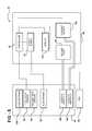
- FIG. 1is a block diagram of an electrosurgical apparatus showing interconnections between a handheld unit and a control unit in a bipolar operation;
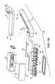
- FIG. 2is a perspective view of the handheld unit showing an electrode positioning mechanism in a second position
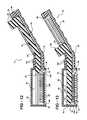
- FIG. 3is a cross-sectional side view of a first embodiment of the handheld unit showing the electrode positioning mechanism in a first position;
- FIG. 4is a cross-sectional side view of a first embodiment of the handheld unit showing the electrode positioning mechanism in the second position;
- FIG. 5is a block diagram of the electrosurgical apparatus showing interconnections between the handheld unit and the control unit in a monopolar operation;
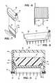
- FIG. 6is a partial front view of a comb of electrodes of the first embodiment
- FIG. 7is an exploded perspective view of the comb of electrodes and a holder
- FIG. 8is a perspective view of the holder holding the comb of electrodes
- FIG. 9is a cross-sectional front view of the first embodiment of the handheld unit showing the electrode positioning mechanism engaging the holder;
- FIG. 10is an exploded perspective view of the first embodiment of the handheld unit
- FIG. 11is an exploded perspective view of a plurality of holders connected by a wire in the monopolar operation
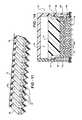
- FIG. 12is a cross-sectional side view of a second embodiment of the handheld unit showing the electrode positioning mechanism in the first position;
- FIG. 13is a cross-sectional side view of a second embodiment of the handheld unit showing the electrode positioning mechanism in the second position;
- FIG. 14is a cross-sectional front view of the second embodiment of the handheld unit showing the electrode positioning mechanism engaging capsules supporting the electrodes;
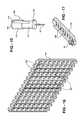
- FIG. 15is a perspective view of one of the capsules of the second embodiment supporting one of the electrodes
- FIG. 16is a perspective view of a plate of the second embodiment for supporting a plurality of capsules
- FIG. 17is a perspective view of a conductive strip of the second embodiment for conducting electrical current to a plurality of capsules
- FIG. 18is an exploded perspective view of a plurality of plates connected by wires in the bipolar operation
- FIG. 19is cross-sectional side view of a third embodiment of the handheld unit showing the electrode positioning mechanism in the first position
- FIG. 20is cross-sectional side view of the third embodiment of the handheld unit showing the electrode positioning mechanism in the second position
- FIG. 21is a cross-sectional front view of the third embodiment of the handheld unit showing the electrode positioning mechanism engaging a block supporting the electrodes;
- FIG. 22is a perspective view of the block of the third embodiment.
- an electrosurgical apparatus 30is shown in FIG. 1 .
- the apparatus 30is capable of delivering electrical current to skin using a plurality of electrodes 32 which enter the skin.
- the apparatus 30is utilized in skin tightening procedures.
- other uses of the apparatus 30will be evident to those skilled in the art.
- the apparatus 30includes a handheld unit 34 , as shown in FIG. 2 .
- the handheld unit 34includes a housing 36 for supporting and concealing the plurality of electrodes 32 as well as other components described in greater detail below.
- the housing 36is preferably formed of plastic; however, other materials may also be suitable, including, but not limited to, fiberglass or metal.
- the housing 36is connected to a handle portion 38 .
- the handle portion 38designed to be held by an operator of the apparatus 30 , such as a physician, nurse, or technician.
- the housing 36defines a cavity 40 in which the electrodes 32 are concealed when not in operation.
- the housing 36includes an edge 42 defining an opening 44 providing access to the cavity 40 .
- the edge 42includes a plurality of edge segments 43 .
- the edge segments 43are coplanar with one another.
- the edge 42forms a substantially flat surface.
- the edge 42preferably also includes a seal 46 formed of an elastomeric material, such as rubber. However, other materials may be utilized to form the seal 46 .
- the edge 42 and/or the seal 46are disposable on the skin as is described in greater detail below.
- each of the electrodes 32is generally perpendicular with the edge when the electrode 32 is in the second position. Said another way, the electrode 32 extends “straight into” the skin at about a 90 degree angle. This direction of entry causes the least damage to the skin to quicken surgical recovery time.
- the apparatus 30also includes a control unit 48 .
- the control unit 48is preferably separate from the handheld unit 34 to manage the overall weight of the handheld unit 34 .
- those skilled in the artrealize that some or all of the features of the control unit 48 may be incorporated within the handheld unit 34 if desired.
- the control unit 48includes a power supply 50 for supplying the electrical current to the electrodes 32 .
- the power supply 50preferably converts commercial AC electrical power, e.g., a 120 volt, 60 hertz signal, to a radio frequency (RF) signal, i.e., an AC signal operating at a radio frequency.
- RFradio frequency
- a cable (not shown) or other electrical connectionallows transmission of the RF signal from the power supply 50 in the control unit 48 to the electrodes 32 in the handheld unit 34 .
- One or more wires 51are preferably disposed within the housing 36 of the handheld unit 34 to conduct the RF signal within the handheld unit 34 .
- the control unit 48also preferably includes a controller 52 for controlling operation of the apparatus 30 .
- the controller 52is preferably implemented as a microprocessor-based device. However, the controller 52 may be implemented as a logic circuit or other implementation as well known to those skilled in the art.
- the apparatus 30may be configured for either bipolar or monopolar operation. Specifically, in bipolar operation, as shown in FIG. 1 , the RF signal is applied through a first set 54 of the electrodes 32 and utilizes a second set 56 of electrodes 32 as a return path to the power supply 50 . In monopolar operation, as shown in FIG. 5 , the RF signal is applied through all of the electrodes 32 and a pad 58 , connectable to the skin of the patient, provides the return path to the power supply 50 .
- the electrodes 32are preferably formed of a metal such that they are electrically conductive. Most preferably, the electrodes 32 are formed of stainless steel, but other suitable materials are known to those skilled in the art. Each electrode 32 is preferably shaped like a needle. That is, an end of each electrode forms a sharp, angled point allowing the electrode 32 to puncture the skin.
- each electrode 32convey electrical current to the skin.
- each electrode 32is partially coated with a dielectric, i.e., nonconductive, coating 60 .
- the dielectric coating 60acts as an insulator to prevent the conduction of the electric current out of the electrode 32 at areas of the electrode 32 covered by the coating. More preferably, about 0.5 mm of each electrode, at a tip end of the electrode, is uncoated with the dielectric coating. Thus, the electric current flows from the electrode at the tip end.
- Each of the electrodes 32is movable between a first position and a second position.
- the electrode 32In the first position, as shown in FIG. 3 , the electrode 32 is completely concealed within the cavity 40 formed by the housing 36 , i.e., the electrode 32 does not protrude through the opening 44 .
- the first positionmay be referred to as the retracted position.
- the electrode 32In the second position, as shown in FIG. 4 , the electrode 32 protrudes through the opening 44 . This second position may be referred to as an extended position.
- the edge 42 and/or seal 46is disposed on the skin of the patient, the electrode 32 will pierce the skin in the second position.
- the apparatusincludes an electrode positioning mechanism 74 operatively engageable with the electrodes 32 for moving the electrodes 32 between the first and second positions.
- the mechanism 74operatively engages at least one electrode 32 as it moves.
- the mechanism 74operatively engages at least two of the plurality of electrodes 32 simultaneously such that the at least two electrodes 32 move between the positions in unison.
- the handle portion 38defines at least one channel 76 that accommodates the mechanism 74 .
- the mechanism 74slidably engages the handle portion 38 while sliding through the channel 76 .
- the handle portion 38includes at least one bend 78 such that part of the handle portion 38 is non-parallel to the edge 42 of the housing 36 , as shown in FIGS. 3 and 4 .
- the mechanism 74must be flexible to accommodate the change in direction provided by the bend 78 and other contours formed by the housing 36 .
- the mechanism 74is preferably formed of an elastomeric material.
- the mechanism 74may be formed of any other flexible material.
- it is preferred that the mechanism 74is non-conductive or coated with a non-conductive material.
- the mechanism 74includes a proximal end 80 and a distal end 82 .
- the distal end 82is tapered to provide an angled surface 84 for operatively engaging the electrodes 32 as the mechanism 74 is moved from the first position to the second position.
- the proximal end 80 of the mechanismincludes an engagement tab 86 .
- the engagement tab 86allows manual operation of the mechanism 74 by the user.
- the engagement tab 86 and handle portion 38mechanically engage one another to prevent unintended movement of the mechanism 74 towards the first position.
- the housing 34defines saw-tooth stubs 88 projecting into the channel 76 and the engagement tab 86 includes ribs 90 for engaging the stubs 88 .
- the usersqueezes walls (not numbered) of the tab 86 together to release the ribs 80 from the stubs 88 and allow the mechanism 74 to slide freely.
- other manual techniques for preventing movement of the mechanism 74are known to those skilled in the art.
- automatically powered techniquese.g., a motor, may be implemented to move the mechanism 74 between the first and second positions.
- the handheld unit 34preferably includes at least one sensor 94 , 96 for sensing the position of the mechanism.
- the at least one sensor 94 , 96is implemented as a first proximity sensor 94 disposed adjacent one longitudinal end of the channel 76 and a second proximity sensor 96 disposed adjacent the other longitudinal end of the channel 76 .
- the proximity sensors 94 , 96sense the presence of the engagement tab 86 of the electrode positioning mechanism 74 .
- the first proximity sensor 94senses when the mechanism 74 is fully retracted, i.e., when the mechanism 74 is not engaging any of the electrodes 32 , such that all electrodes 32 are in the first position.
- the second proximity sensor 96senses when the mechanism 74 is fully extended, i.e., when the mechanism 74 is engaging all of the electrodes 32 , such that all electrodes 32 are in the second position.
- the proximity sensors 94 , 96are in communication with the controller 52 to communicate the position of the mechanism 74 to the controller 52 .
- a communications cable(not shown) electrically connects the proximity sensors 94 , 96 to the controller.
- FIGS. 3, 4, and 6-10illustrate a first embodiment of the invention.
- the electrodes 32are arranged into a plurality of combs 62 .
- each comb 62is preferably formed of a single piece of metal which defines several electrodes 32 .
- a flat section 64electrically connects the electrodes 32 of each comb 62 together.
- a pin 66extends from the flat section 64 opposite the electrodes 32 to allow electrical connection to the comb 62 .
- the flat section 64 of each combis insulated with a dielectric coating. It is also preferred that a portion of each electrode 32 is insulated with the dielectric coating, as described above, to leave about 0.5 mm of each electrode 32 exposed to conduct the electrical current.
- each comb 62is supported by a holder 68 , as shown in FIGS. 7 and 8 .
- the holder 68is preferably formed of a non-conductive, i.e., insulating material, such as plastic.
- Each holder 68includes a pair of tabs 70 to slidably engage in grooves 72 defined in the housing 36 of the handheld unit 34 .
- the grooves 72are best observed with reference to FIG. 10 .
- the holder 68may slide to move the electrodes 32 from the first to the second position when engaged by the electrode positioning mechanism 74 .
- the combs 62 and holders 68are arranged in successive rows.
- At least one coil 92extends from a top of each holder 68 to return the holder 68 and the electrodes 32 to the first position after retreat of the mechanism 74 .
- the coil 92electrically connects the comb 92 to one of the wires 51 .
- the coil 92 of each holder 68 in successive rowsalternates between the two wires 51 , where one wire 51 provides a supply path from the power supply 50 and the other wire 51 provides a return path.
- the monopolar configurationas shown in FIG. 11 , only one wire 51 is utilized as a supply path.
- the apparatus 30includes a vacuum pump 98 , preferably disposed within the control unit 48 , as shown in FIG. 1 .
- the vacuum pump 98is operatively connected to a motor (not shown) and generates a vacuum as is well known to those skilled in the art.
- the vacuum pump 98is in fluid communication with the cavity 40 of the handheld unit 34 .
- the vacuum pump 98provides suction in the cavity 40 such that the edge 42 of the housing and/or the seal 46 sealingly engages with the skin when a vacuum is applied.
- a vacuum manifold 100is disposed within the cavity 40 to provide an even suction throughout the length of the cavity 40 .
- the vacuum manifold 100is preferably in fluid communication with the vacuum pump 98 via vacuum tubing and/or a vacuum cylinders (neither numbered) molded into the housing 36 .
- vacuum tubingand/or a vacuum cylinders (neither numbered) molded into the housing 36 .
- the apparatus 30also includes a coolant supply 102 .
- the coolant supply 102is also preferably disposed within the control unit 48 .
- the coolant supply 102is in fluid communication with the cavity 40 for supplying a coolant directly to the skin.
- the coolantis preferably not electrically conductive, i.e., a dielectric, such that the coolant will not create electrical arcs between the electrodes 32 .
- the coolantmay be deionized water, however other suitable coolants are known to those skilled in the art.
- a coolant pump(not shown) may be utilized to pump coolant from the coolant supply 102 to the cavity 40 .
- a coolant manifold 104is preferably disposed within the cavity 40 and in fluid communication with the coolant supply 102 for evenly applying the coolant to the skin.
- the handheld unit 34includes a plurality of pushbuttons 105 for controlling operation of the apparatus 30 .
- the pushbuttons 105are preferably in communication with the controller 52 , i.e., the pushbuttons 105 are electrically connected to the controller 52 .
- the pushbuttons 105working in coordination with the controller 52 , allow control over the overall power of the apparatus 30 , the application of the vacuum, the application of the coolant, and the energization of the electrodes 32 .
- those skilled in the artrealize other suitable user interfaces for control of the apparatus 30 besides the preferred pushbuttons 105 .
- the pushbuttons 105may include light emitting diodes (LEDs) (not shown) or other light generating sources to provide feedback to the user as to the status of the overall power, vacuum, coolant, and electrodes 32 .
- the control panel 48may also include a display 132 for also displaying these statuses, as well as other aspects of the apparatus 30 .
- a speaker(not shown) may be integrated with the handheld device 34 or the control panel 48 to provide audible feedback to apparatus 30 functionality.
- the apparatus 30may be utilized in skin tightening procedures.
- the handheld unit 34is positioned such that the opening 44 is disposed over the area of skin to be treated. Accordingly, the edge 42 and/or seal 46 is placed in contact with the skin.
- the vacuum pump 98is activated, preferably using the pushbuttons 105 .
- a vacuum suctionoccurs within the cavity 40 .
- the edge 42 and/or seal 46thus sealingly engage the skin.
- the electrode positioning mechanism 74is pushed inwards toward the cavity 40 .
- the mechanism 74engages the electrodes 32 , moving them from the first position to the second position.
- the electrodes 32pierce the skin during this movement.
- the electrodes 32penetrate the skin to a maximum depth of about 0.8 to 2.3 mm when in the second position. As stated above, it is preferred that only 0.5 mm of each electrode 32 is not coated with the dielectric coating and thus is able to conduct electricity to the skin. For the skin tightening procedure, it is preferred that this exposed portion of the electrodes 32 is disposed in the subcutaneous layer of the skin.
- the second proximity sensor 96senses when the mechanism 74 is fully extended, and thus all electrodes 32 are in the second position.
- the coolantmay then be applied to the skin.
- the controller 52will activate the coolant pump in sequence when the appropriate pushbutton 105 is pressed.
- the controller 52preferably prevents coolant application until the mechanism 74 is in the second position and the vacuum is maintained.
- the controller 52may automatically apply the coolant once the mechanism 74 reaches the second position without activation of the pushbutton 105 .
- the coolantdisperses from the coolant manifold 104 which is on the opposite side of the cavity 40 from the vacuum manifold 100 . Accordingly, the coolant is suctioned across from the coolant manifold 104 , across the skin, and into the vacuum manifold 100 . Thus, coolant is applied directly and evenly to all portions of the skin within the edges 42 . Since the coolant is applied directly to the skin, it is very effective in cooling the outer layer of the skin during the procedure.
- the vacuum pump 98 and coolant supply 102may be interconnected to recover coolant used in the procedure.
- the coolant used in the proceduremay be disposed of to avoid contamination.
- the electric currentis then applied to the skin via the electrodes 32 .
- activation of the electrodes 32is via the appropriate pushbutton 105 .
- application of the electric currentmay be automatic after application of the coolant.
- the electric currentis supplied as an RF signal.
- the electric currentmay be activated and maintained for a set length of time.
- the electric currentmay be deactivated based on a measured resistance of the skin, as is well known to those skilled in the art.
- the coolantcontinues to flow while the electric current is activated, to cool the skin while being heated by the electrodes 32 .
- the coolantmay be deactivated as well.
- the electrodes 32are preferably retracted to their first position by moving the mechanism 86 from the second position back to the first position.
- the vacuumis deactivated and the handheld unit 34 is removed from the patient's skin.
- the handheld unit 34may be repositioned on other areas of the skin to repeat the procedure as necessary.
- the apparatus 30creates mechanical and thermal injuries to the skin. As these injuries heal, the effect is tightening of the skin, which is normally perceived to be the appearance of younger and tighter skin.
- each electrode 32is part of an individualized capsule 106 preferably having a cylindrical shape.
- the capsule 106acts as the electrode carrier.
- each capsule 106is formed as a unitary part formed of a metal, such as stainless steel.
- the electrode 32extends from a disc 108 .
- the disc and portions of the electrodeare coated with the dielectric coating to prevent electric current from flowing out of the disc 108 or coated portions of the electrode 32 .
- about 0.5 mm of each electrode, at the tip end of the electrode 32is uncoated.
- a throat 110extends from the other side of the disc 108 opposite of the electrode 32 and a shoulder 112 extends from the throat 110 .
- the throat 110has a diameter that is less than a diameter of the plate 108 and the shoulder 112 .
- the throat 110 and shoulder 112are not covered with the dielectric coating such that electric current may flow though them.
- Each capsule 106defines a slot 114 extending through the shoulder 112 and into the throat 110 .
- the slot 114allows the capsule 106 to be compressed for removal as described below.
- the shoulder 112 of each capsule 106also defines a beveled top edge 116 .
- the beveled top edge 116 of the capsule 106engages with the angled surface 84 of the electrode positioning mechanism 74 .
- the handheld unit 34 of the second embodimentalso includes at least one plate 118 for supporting the capsules 106 .
- the plate 118is preferably formed of plastic or other non-conductive material. Alternatively, the plate may be formed of a metal and coated to prevent electrical conduction.
- the plate 118defines a plurality of holes 120 . The diameter of each hole 120 is sized larger than the diameter of the throat 110 of each capsule 106 , but smaller than the diameter of the disc 108 and the shoulder 112 . Accordingly, the throat 110 of the capsule may slidably engage the plate 118 to move between the first and second positions.
- Each capsule 106may be removed from the plate 118 by compressing the capsule 106 as described above.
- the plate 118also defines recesses 122 that encompass a plurality of holes 120 , such as a row or column of holes 120 .
- the recesses 122each accommodate a conductive strip 124 , as shown in FIG. 17 .
- Each conductive strip 124is formed of a conductive material, such as metal, and also defines a plurality of holes 126 that align with the holes 120 of the plate 118 . Therefore, each capsule 106 slidably engages both the plate 118 and the conductive strip 124 . Accordingly, the capsules 106 and electrodes 32 in each row (or column) are electrically connected together. At least one coil 92 extends from a top of each conductive strip 124 .
- the coil 92 in the second embodimentfunctions to return the electrodes 32 to the first position after retreat of the electrode positioning mechanism 74 .
- the coil 92serves as the electrical contact between the conductive strip 124 and the wire 51 , as shown in FIG. 18 .
- the electrodes 32are supported by and project from a block 128 .
- the blockacts as the electrode carrier.
- the block 128is formed of a flexible material allowing it to curve and bend, as can be seen in FIG. 19 .
- the electrodes 32are divided into a groups (not numbered) of electrodes 32 that are electrically connected together within the block 128 . Each group includes a pin 130 extending out of the block 128 for electrical connection to the power supply.
- the groups of electrodes 32may be arranged in rows or columns or other suitable patterns.
Landscapes
- Health & Medical Sciences (AREA)
- Surgery (AREA)
- Engineering & Computer Science (AREA)
- Life Sciences & Earth Sciences (AREA)
- Biomedical Technology (AREA)
- Otolaryngology (AREA)
- Nuclear Medicine, Radiotherapy & Molecular Imaging (AREA)
- Plasma & Fusion (AREA)
- Physics & Mathematics (AREA)
- Heart & Thoracic Surgery (AREA)
- Medical Informatics (AREA)
- Molecular Biology (AREA)
- Animal Behavior & Ethology (AREA)
- General Health & Medical Sciences (AREA)
- Public Health (AREA)
- Veterinary Medicine (AREA)
- Surgical Instruments (AREA)
Abstract
Description
Claims (25)
Priority Applications (1)
| Application Number | Priority Date | Filing Date | Title |
|---|---|---|---|
| US11/773,705US9737359B2 (en) | 2006-07-05 | 2007-07-05 | Apparatus and method for skin tightening and corrective forming |
Applications Claiming Priority (2)
| Application Number | Priority Date | Filing Date | Title |
|---|---|---|---|
| US81870206P | 2006-07-05 | 2006-07-05 | |
| US11/773,705US9737359B2 (en) | 2006-07-05 | 2007-07-05 | Apparatus and method for skin tightening and corrective forming |
Publications (2)
| Publication Number | Publication Date |
|---|---|
| US20090105706A1 US20090105706A1 (en) | 2009-04-23 |
| US9737359B2true US9737359B2 (en) | 2017-08-22 |
Family
ID=38895209
Family Applications (1)
| Application Number | Title | Priority Date | Filing Date |
|---|---|---|---|
| US11/773,705Active2031-02-13US9737359B2 (en) | 2006-07-05 | 2007-07-05 | Apparatus and method for skin tightening and corrective forming |
Country Status (4)
| Country | Link |
|---|---|
| US (1) | US9737359B2 (en) |
| EP (1) | EP2034917A2 (en) |
| CN (2) | CN101534734B (en) |
| WO (1) | WO2008005477A2 (en) |
Cited By (2)
| Publication number | Priority date | Publication date | Assignee | Title |
|---|---|---|---|---|
| USD850638S1 (en) | 2017-12-05 | 2019-06-04 | Hoon Cha | Electronic skin care device |
| US11250492B2 (en)* | 2016-03-22 | 2022-02-15 | Paypal, Inc. | Automatic population of data on an internet web page via a browser plugin |
Families Citing this family (24)
| Publication number | Priority date | Publication date | Assignee | Title |
|---|---|---|---|---|
| US20060047281A1 (en) | 2004-09-01 | 2006-03-02 | Syneron Medical Ltd. | Method and system for invasive skin treatment |
| US8700176B2 (en) | 2006-07-27 | 2014-04-15 | Pollogen Ltd. | Apparatus and method for non-invasive treatment of skin tissue |
| TW200831446A (en) | 2006-11-15 | 2008-08-01 | Du Pont | Processes for producing pentafluoropropenes and certain azeotropes comprising HF and certain halopropenes of the formula C3HCIF4 |
| WO2009047774A2 (en)* | 2007-10-09 | 2009-04-16 | Transpharma Ltd. | Magnetic patch coupling |
| JP2011505899A (en)* | 2007-12-05 | 2011-03-03 | シネロン メディカル リミテッド | Disposable electromagnetic energy applicator and method of using the same |
| MX2010007860A (en) | 2008-01-17 | 2010-11-30 | Syneron Medical Ltd | A hair removal apparatus for personal use and the method of using same. |
| EP2237732A4 (en)* | 2008-01-24 | 2011-06-01 | Syneron Medical Ltd | A device, apparatus, and method of adipose tissue treatment |
| WO2012118293A2 (en) | 2011-03-03 | 2012-09-07 | Na Jongju | Skin care method, apparatus and system |
| EP2334249B1 (en) | 2008-09-21 | 2013-03-13 | Syneron Medical Ltd. | A method and apparatus for personal skin treatment |
| US8357150B2 (en) | 2009-07-20 | 2013-01-22 | Syneron Medical Ltd. | Method and apparatus for fractional skin treatment |
| US8606366B2 (en) | 2009-02-18 | 2013-12-10 | Syneron Medical Ltd. | Skin treatment apparatus for personal use and method for using same |
| US20100211055A1 (en)* | 2009-02-18 | 2010-08-19 | Shimon Eckhouse | Method for body toning and an integrated data management system for the same |
| EP2730313A1 (en) | 2009-02-25 | 2014-05-14 | Syneron Medical Ltd. | Electrical skin rejuvenation |
| US20120158100A1 (en)* | 2010-06-21 | 2012-06-21 | Kevin Schomacker | Driving Microneedle Arrays into Skin and Delivering RF Energy |
| EP4309639A3 (en) | 2011-06-14 | 2024-02-14 | ViOL Co., Ltd. | Apparatus and method for improving skin using a ra-effect or ra plus-effect |
| KR101286752B1 (en)* | 2012-09-03 | 2013-07-16 | 라종주 | Apparatus for surgical procedure in the body, and endoscope equipped therewith |
| US9788887B2 (en)* | 2015-02-20 | 2017-10-17 | Elliquence | Surgical tool and method having multiple electrodes |
| US10220195B2 (en)* | 2016-06-08 | 2019-03-05 | Eclipse Medcorp, Llc | Radio frequency needling device for use with disposable needle cartridges |
| WO2019046333A1 (en)* | 2017-08-29 | 2019-03-07 | Patchmi, Inc. | Microneedle treatment system |
| KR102192606B1 (en)* | 2018-09-06 | 2020-12-17 | 주식회사 루트로닉 | A Handpiece for treatment, AN TREATMENT APPARATUS AND A METHOD FOR CONTROLLING THAT |
| KR102147856B1 (en)* | 2019-07-17 | 2020-08-25 | 주식회사 제이시스메디칼 | Needle tip for providing current, handpiece and skin treating device |
| KR102156034B1 (en)* | 2019-09-17 | 2020-09-15 | (주)제이시스메디칼 | Apparatus for treating skin using radio frequency |
| WO2021224678A1 (en) | 2020-05-04 | 2021-11-11 | Btl Medical Technologies S.R.O. | Device and method for unattended treatment of a patient |
| US11878167B2 (en) | 2020-05-04 | 2024-01-23 | Btl Healthcare Technologies A.S. | Device and method for unattended treatment of a patient |
Citations (41)
| Publication number | Priority date | Publication date | Assignee | Title |
|---|---|---|---|---|
| US4920968A (en) | 1987-01-20 | 1990-05-01 | Haruo Takase | Needle base with plural needles for subcutaneously applying electric current |
| US5452513A (en)* | 1994-06-29 | 1995-09-26 | Eric Hulsman | Suture cutter |
| US5582611A (en)* | 1992-05-19 | 1996-12-10 | Olympus Optical Co., Ltd. | Surgical device for stapling and/or fastening body tissues |
| US5611806A (en) | 1994-05-23 | 1997-03-18 | Samsung Electro-Mechanics Co., Ltd. | Skin perforating device for transdermal medication |
| US5618295A (en) | 1993-10-16 | 1997-04-08 | Samsung Electro-Mechanics Co., Ltd. | Apparatus for preparing skin in advance |
| US5660836A (en) | 1995-05-05 | 1997-08-26 | Knowlton; Edward W. | Method and apparatus for controlled contraction of collagen tissue |
| US5755753A (en) | 1995-05-05 | 1998-05-26 | Thermage, Inc. | Method for controlled contraction of collagen tissue |
| US5948011A (en) | 1995-05-05 | 1999-09-07 | Thermage, Inc. | Method for controlled contraction of collagen tissue via non-continuous energy delivery |
| US5964729A (en) | 1994-05-23 | 1999-10-12 | Samsung Electro-Mechanics Co., Ltd. | Perforating device for dermal administration |
| US6277116B1 (en) | 1994-05-06 | 2001-08-21 | Vidaderm | Systems and methods for shrinking collagen in the dermis |
| US6391038B2 (en)* | 1999-07-28 | 2002-05-21 | Cardica, Inc. | Anastomosis system and method for controlling a tissue site |
| US6428538B1 (en)* | 1995-10-20 | 2002-08-06 | United States Surgical Corporation | Apparatus and method for thermal treatment of body tissue |
| US20020120260A1 (en)* | 2001-02-28 | 2002-08-29 | Morris David L. | Tissue surface treatment apparatus and method |
| US6556869B1 (en) | 1999-12-01 | 2003-04-29 | Vertis Neuroscience, Inc. | Electrode introducer for a percutaneous electrical therapy system |
| US20030153905A1 (en)* | 2002-01-25 | 2003-08-14 | Edwards Stuart Denzil | Selective ablation system |
| US20030216727A1 (en)* | 2001-03-30 | 2003-11-20 | Long Gary L. | Medical device with improved wall construction |
| US6697670B2 (en) | 2001-08-17 | 2004-02-24 | Minnesota Medical Physics, Llc | Apparatus and method for reducing subcutaneous fat deposits by electroporation with improved comfort of patients |
| US6743211B1 (en) | 1999-11-23 | 2004-06-01 | Georgia Tech Research Corporation | Devices and methods for enhanced microneedle penetration of biological barriers |
| US6795728B2 (en) | 2001-08-17 | 2004-09-21 | Minnesota Medical Physics, Llc | Apparatus and method for reducing subcutaneous fat deposits by electroporation |
| US6892099B2 (en) | 2001-02-08 | 2005-05-10 | Minnesota Medical Physics, Llc | Apparatus and method for reducing subcutaneous fat deposits, virtual face lift and body sculpturing by electroporation |
| US20050145671A1 (en)* | 2002-05-10 | 2005-07-07 | Viola Frank J. | Surgical stapling apparatus having a wound closure material applicator assembly |
| US20050159778A1 (en)* | 2002-05-10 | 2005-07-21 | Russell Heinrich | Electrosurgical stapling apparatus |
| US7013179B2 (en) | 2000-01-07 | 2006-03-14 | Biowave Corporation | Percutaneous electrode array |
| US20060085056A1 (en) | 2004-10-19 | 2006-04-20 | Schouenborg Jens O R | Method and means for electrical stimulation of cutaneous sensory receptors |
| US20060089688A1 (en) | 2004-10-25 | 2006-04-27 | Dorin Panescu | Method and apparatus to reduce wrinkles through application of radio frequency energy to nerves |
| US20070142885A1 (en) | 2005-11-29 | 2007-06-21 | Reliant Technologies, Inc. | Method and Apparatus for Micro-Needle Array Electrode Treatment of Tissue |
| US20080082090A1 (en) | 2004-04-01 | 2008-04-03 | The General Hospital Corporation | Method and apparatus for dermatological treatment and tissue reshaping |
| US20090093864A1 (en) | 2007-10-08 | 2009-04-09 | Anderson Robert S | Methods and devices for applying energy to tissue |
| US20090112205A1 (en)* | 2007-10-31 | 2009-04-30 | Primaeva Medical, Inc. | Cartridge electrode device |
| US7585297B2 (en) | 1998-02-27 | 2009-09-08 | James A Baker | RF electrode array for low-rate collagen shrinkage in capsular shift procedures and methods of use |
| US20100023003A1 (en) | 2005-12-22 | 2010-01-28 | Spamedica International Srl | Skin rejuvination resurfacing device and method of use |
| US20100116867A1 (en)* | 2008-11-10 | 2010-05-13 | Balbierz Daniel J | Multi-fire stapling systems and methods for delivering arrays of staples |
| US7824394B2 (en) | 2004-04-01 | 2010-11-02 | The General Hospital Corporation | Method and apparatus for dermatological treatment and tissue reshaping |
| US20110009737A1 (en) | 2009-06-09 | 2011-01-13 | The General Hospital Corporation | Method and apparatus for dermatological treatment and tissue reshaping |
| US20110092884A1 (en) | 2009-01-23 | 2011-04-21 | Dong Hwan Kang | Device for Skin Treatment |
| US20110130618A1 (en) | 2008-06-29 | 2011-06-02 | Venus Technologies Ltd | Esthetic apparatus useful for increasing skin rejuvenation and methods thereof |
| US8007493B2 (en) | 2006-10-16 | 2011-08-30 | Syneron Medical Ltd. | Methods and devices for treating tissue |
| US20110270364A1 (en) | 2007-08-01 | 2011-11-03 | Syneron Medical Ltd. | Method and device for collagen growth stimulation |
| US8133216B2 (en) | 2006-10-16 | 2012-03-13 | Syneron Medical Ltd. | Methods and devices for treating tissue |
| US20120150266A1 (en) | 2009-08-04 | 2012-06-14 | Pinchas Shalev | Cosmetic skin rejuvination |
| US20120158100A1 (en) | 2010-06-21 | 2012-06-21 | Kevin Schomacker | Driving Microneedle Arrays into Skin and Delivering RF Energy |
- 2007
- 2007-07-05WOPCT/US2007/015441patent/WO2008005477A2/enactiveApplication Filing
- 2007-07-05EPEP07796668Apatent/EP2034917A2/ennot_activeWithdrawn
- 2007-07-05CNCN2007800307592Apatent/CN101534734B/enactiveActive
- 2007-07-05CNCN201210210684.9Apatent/CN102764154B/enactiveActive
- 2007-07-05USUS11/773,705patent/US9737359B2/enactiveActive
Patent Citations (56)
| Publication number | Priority date | Publication date | Assignee | Title |
|---|---|---|---|---|
| US4920968A (en) | 1987-01-20 | 1990-05-01 | Haruo Takase | Needle base with plural needles for subcutaneously applying electric current |
| US5582611A (en)* | 1992-05-19 | 1996-12-10 | Olympus Optical Co., Ltd. | Surgical device for stapling and/or fastening body tissues |
| US5618295A (en) | 1993-10-16 | 1997-04-08 | Samsung Electro-Mechanics Co., Ltd. | Apparatus for preparing skin in advance |
| US6277116B1 (en) | 1994-05-06 | 2001-08-21 | Vidaderm | Systems and methods for shrinking collagen in the dermis |
| US5964729A (en) | 1994-05-23 | 1999-10-12 | Samsung Electro-Mechanics Co., Ltd. | Perforating device for dermal administration |
| US5611806A (en) | 1994-05-23 | 1997-03-18 | Samsung Electro-Mechanics Co., Ltd. | Skin perforating device for transdermal medication |
| US5452513A (en)* | 1994-06-29 | 1995-09-26 | Eric Hulsman | Suture cutter |
| US6377855B1 (en) | 1995-05-05 | 2002-04-23 | Thermage, Inc. | Method and apparatus for controlled contraction of collagen tissue |
| US6387380B1 (en) | 1995-05-05 | 2002-05-14 | Thermage, Inc. | Apparatus for controlled contraction of collagen tissue |
| US5948011A (en) | 1995-05-05 | 1999-09-07 | Thermage, Inc. | Method for controlled contraction of collagen tissue via non-continuous energy delivery |
| US5871524A (en) | 1995-05-05 | 1999-02-16 | Thermage, Inc. | Apparatus for controlled contraction of collagen tissue |
| US6241753B1 (en) | 1995-05-05 | 2001-06-05 | Thermage, Inc. | Method for scar collagen formation and contraction |
| US5755753A (en) | 1995-05-05 | 1998-05-26 | Thermage, Inc. | Method for controlled contraction of collagen tissue |
| US6311090B1 (en) | 1995-05-05 | 2001-10-30 | Thermage, Inc. | Method and apparatus for controlled contraction of collagen tissue |
| US5660836A (en) | 1995-05-05 | 1997-08-26 | Knowlton; Edward W. | Method and apparatus for controlled contraction of collagen tissue |
| US6377854B1 (en) | 1995-05-05 | 2002-04-23 | Thermage, Inc. | Method for controlled contraction of collagen in fibrous septae in subcutaneous fat layers |
| US6381497B1 (en) | 1995-05-05 | 2002-04-30 | Thermage, Inc. | Method for smoothing contour irregularity of skin surface by controlled contraction of collagen tissue |
| US6381498B1 (en) | 1995-05-05 | 2002-04-30 | Thermage, Inc. | Method and apparatus for controlled contraction of collagen tissue |
| US5919219A (en) | 1995-05-05 | 1999-07-06 | Thermage, Inc. | Method for controlled contraction of collagen tissue using RF energy |
| US6453202B1 (en) | 1995-05-05 | 2002-09-17 | Thermage, Inc. | Method and apparatus for controlled contraction of collagen tissue |
| US6405090B1 (en) | 1995-05-05 | 2002-06-11 | Thermage, Inc. | Method and apparatus for tightening skin by controlled contraction of collagen tissue |
| US6428538B1 (en)* | 1995-10-20 | 2002-08-06 | United States Surgical Corporation | Apparatus and method for thermal treatment of body tissue |
| US7585297B2 (en) | 1998-02-27 | 2009-09-08 | James A Baker | RF electrode array for low-rate collagen shrinkage in capsular shift procedures and methods of use |
| US6391038B2 (en)* | 1999-07-28 | 2002-05-21 | Cardica, Inc. | Anastomosis system and method for controlling a tissue site |
| US6743211B1 (en) | 1999-11-23 | 2004-06-01 | Georgia Tech Research Corporation | Devices and methods for enhanced microneedle penetration of biological barriers |
| US6556869B1 (en) | 1999-12-01 | 2003-04-29 | Vertis Neuroscience, Inc. | Electrode introducer for a percutaneous electrical therapy system |
| US7013179B2 (en) | 2000-01-07 | 2006-03-14 | Biowave Corporation | Percutaneous electrode array |
| US7130696B2 (en) | 2000-01-07 | 2006-10-31 | Biowave Corporation | Percutaneous electrode array |
| US6892099B2 (en) | 2001-02-08 | 2005-05-10 | Minnesota Medical Physics, Llc | Apparatus and method for reducing subcutaneous fat deposits, virtual face lift and body sculpturing by electroporation |
| US20020120260A1 (en)* | 2001-02-28 | 2002-08-29 | Morris David L. | Tissue surface treatment apparatus and method |
| US20030216727A1 (en)* | 2001-03-30 | 2003-11-20 | Long Gary L. | Medical device with improved wall construction |
| US6697670B2 (en) | 2001-08-17 | 2004-02-24 | Minnesota Medical Physics, Llc | Apparatus and method for reducing subcutaneous fat deposits by electroporation with improved comfort of patients |
| US6795728B2 (en) | 2001-08-17 | 2004-09-21 | Minnesota Medical Physics, Llc | Apparatus and method for reducing subcutaneous fat deposits by electroporation |
| US20030153905A1 (en)* | 2002-01-25 | 2003-08-14 | Edwards Stuart Denzil | Selective ablation system |
| US20050145671A1 (en)* | 2002-05-10 | 2005-07-07 | Viola Frank J. | Surgical stapling apparatus having a wound closure material applicator assembly |
| US20050159778A1 (en)* | 2002-05-10 | 2005-07-21 | Russell Heinrich | Electrosurgical stapling apparatus |
| US7824394B2 (en) | 2004-04-01 | 2010-11-02 | The General Hospital Corporation | Method and apparatus for dermatological treatment and tissue reshaping |
| US20080082090A1 (en) | 2004-04-01 | 2008-04-03 | The General Hospital Corporation | Method and apparatus for dermatological treatment and tissue reshaping |
| US20110046615A1 (en) | 2004-04-01 | 2011-02-24 | The General Hospital Corporation | Method and apparatus for dermatological treatment and tissue reshaping |
| US20060085056A1 (en) | 2004-10-19 | 2006-04-20 | Schouenborg Jens O R | Method and means for electrical stimulation of cutaneous sensory receptors |
| US20060089688A1 (en) | 2004-10-25 | 2006-04-27 | Dorin Panescu | Method and apparatus to reduce wrinkles through application of radio frequency energy to nerves |
| US20110190726A1 (en) | 2005-11-29 | 2011-08-04 | Reliant Technologies, Inc. | Method and apparatus for micro-needle array electrode treatment of tissue |
| US20070142885A1 (en) | 2005-11-29 | 2007-06-21 | Reliant Technologies, Inc. | Method and Apparatus for Micro-Needle Array Electrode Treatment of Tissue |
| US20100023003A1 (en) | 2005-12-22 | 2010-01-28 | Spamedica International Srl | Skin rejuvination resurfacing device and method of use |
| US8007493B2 (en) | 2006-10-16 | 2011-08-30 | Syneron Medical Ltd. | Methods and devices for treating tissue |
| US8133216B2 (en) | 2006-10-16 | 2012-03-13 | Syneron Medical Ltd. | Methods and devices for treating tissue |
| US8135475B2 (en) | 2007-08-01 | 2012-03-13 | Syneron Medical Ltd. | Method and device for collagen growth stimulation |
| US20110270364A1 (en) | 2007-08-01 | 2011-11-03 | Syneron Medical Ltd. | Method and device for collagen growth stimulation |
| US20090093864A1 (en) | 2007-10-08 | 2009-04-09 | Anderson Robert S | Methods and devices for applying energy to tissue |
| US20090112205A1 (en)* | 2007-10-31 | 2009-04-30 | Primaeva Medical, Inc. | Cartridge electrode device |
| US20110130618A1 (en) | 2008-06-29 | 2011-06-02 | Venus Technologies Ltd | Esthetic apparatus useful for increasing skin rejuvenation and methods thereof |
| US20100116867A1 (en)* | 2008-11-10 | 2010-05-13 | Balbierz Daniel J | Multi-fire stapling systems and methods for delivering arrays of staples |
| US20110092884A1 (en) | 2009-01-23 | 2011-04-21 | Dong Hwan Kang | Device for Skin Treatment |
| US20110009737A1 (en) | 2009-06-09 | 2011-01-13 | The General Hospital Corporation | Method and apparatus for dermatological treatment and tissue reshaping |
| US20120150266A1 (en) | 2009-08-04 | 2012-06-14 | Pinchas Shalev | Cosmetic skin rejuvination |
| US20120158100A1 (en) | 2010-06-21 | 2012-06-21 | Kevin Schomacker | Driving Microneedle Arrays into Skin and Delivering RF Energy |
Non-Patent Citations (1)
| Title |
|---|
| International Search Report and Written Opinion for PCT Application No. PCT/US2007/015441 mailed on Jan. 31, 2008; 9 pages. |
Cited By (3)
| Publication number | Priority date | Publication date | Assignee | Title |
|---|---|---|---|---|
| US11250492B2 (en)* | 2016-03-22 | 2022-02-15 | Paypal, Inc. | Automatic population of data on an internet web page via a browser plugin |
| US12148020B2 (en) | 2016-03-22 | 2024-11-19 | Paypal, Inc. | Automatic population of data for checkout interface |
| USD850638S1 (en) | 2017-12-05 | 2019-06-04 | Hoon Cha | Electronic skin care device |
Also Published As
| Publication number | Publication date |
|---|---|
| CN102764154B (en) | 2015-05-06 |
| EP2034917A2 (en) | 2009-03-18 |
| WO2008005477A2 (en) | 2008-01-10 |
| CN102764154A (en) | 2012-11-07 |
| WO2008005477A3 (en) | 2008-03-27 |
| CN101534734A (en) | 2009-09-16 |
| US20090105706A1 (en) | 2009-04-23 |
| CN101534734B (en) | 2012-08-08 |
Similar Documents
| Publication | Publication Date | Title |
|---|---|---|
| US9737359B2 (en) | Apparatus and method for skin tightening and corrective forming | |
| US20240416050A1 (en) | Medicine injecting tip, hand piece, and skin treating device | |
| US6056747A (en) | Apparatus and method for treatment of body tissues | |
| US8845630B2 (en) | Devices and methods for percutaneous energy delivery | |
| JP6244385B2 (en) | Disposable patch for personal aesthetic skin treatment | |
| JP3428986B2 (en) | Electrosurgical device suitable for laparoscopic surgery | |
| US6102907A (en) | Apparatus and device for use therein and method for ablation of tissue | |
| US8906012B2 (en) | Electrosurgical devices with wire electrode | |
| KR101464058B1 (en) | A disposable electromagnetic energy applicator and method of using it | |
| US20090093864A1 (en) | Methods and devices for applying energy to tissue | |
| US20190209234A1 (en) | Radio frequency handpiece for medical treatments | |
| EP1965715B1 (en) | Liquid delivery apparatus for tissue ablation | |
| US20100210993A1 (en) | Skin treatment apparatus for personal use and method for using same | |
| US20080312648A1 (en) | Fat removal and sculpting device | |
| WO2009104178A2 (en) | A skin treatment apparatus for personal use and method for using same | |
| KR20180111203A (en) | The apparatus of rf treatment and the method of controlling taht and the method of skin treatment using rf-energy | |
| EP2674124B1 (en) | Electrosurgical dissector with thermal management | |
| KR20190022102A (en) | An skin treatment apparatus using rf energy and a method for skin treatment using that | |
| JP2001178740A5 (en) | Endoscopic treatment equipment, probes, and treatment equipment | |
| US9987071B2 (en) | Surgical instrument with end-effector assembly including three jaw members | |
| KR20100096124A (en) | Cartridge electrode device | |
| KR20180111202A (en) | The apparatus of rf treatment and the method of controlling taht and the method of skin treatment using rf-energy | |
| KR20190035663A (en) | The apparatus of rf treatment and the method of controlling taht and the method of skin treatment using rf-energy | |
| CN105686878A (en) | Energizable attachment for surgical devices | |
| CN120078506B (en) | Minimally invasive cutter and system for endoscope with switchable cold and hot therapy states |
Legal Events
| Date | Code | Title | Description |
|---|---|---|---|
| AS | Assignment | Owner name:BOVIE MEDICAL CORPORATION, FLORIDA Free format text:ASSIGNMENT OF ASSIGNORS INTEREST;ASSIGNOR:LIVNEH, STEVE, MR.;REEL/FRAME:019742/0270 Effective date:20070821 | |
| AS | Assignment | Owner name:LIVNEH, STEVE, CANADA Free format text:ASSIGNMENT OF ASSIGNORS INTEREST;ASSIGNOR:BOVIE MEDICAL CORPORATION;REEL/FRAME:028199/0578 Effective date:20120508 | |
| AS | Assignment | Owner name:RF KINETICS INC., CANADA Free format text:ASSIGNMENT OF ASSIGNORS INTEREST;ASSIGNOR:LIVNEH, STEVE;REEL/FRAME:036383/0091 Effective date:20150820 | |
| STCF | Information on status: patent grant | Free format text:PATENTED CASE | |
| MAFP | Maintenance fee payment | Free format text:PAYMENT OF MAINTENANCE FEE, 4TH YR, SMALL ENTITY (ORIGINAL EVENT CODE: M2551); ENTITY STATUS OF PATENT OWNER: SMALL ENTITY Year of fee payment:4 | |
| MAFP | Maintenance fee payment | Free format text:PAYMENT OF MAINTENANCE FEE, 8TH YR, SMALL ENTITY (ORIGINAL EVENT CODE: M2552); ENTITY STATUS OF PATENT OWNER: SMALL ENTITY Year of fee payment:8 | |
| AS | Assignment | Owner name:JIANGSU RONG FU KANG MEDICAL INSTRUMENTS CO., LTD., CHINA Free format text:ASSIGNMENT OF ASSIGNORS INTEREST;ASSIGNOR:RF KINETICS INC.;REEL/FRAME:072065/0441 Effective date:20250813 |