US9737339B2 - Posterio spinal fixation - Google Patents
Posterio spinal fixationDownload PDFInfo
- Publication number
- US9737339B2 US9737339B2US11/667,365US66736505AUS9737339B2US 9737339 B2US9737339 B2US 9737339B2US 66736505 AUS66736505 AUS 66736505AUS 9737339 B2US9737339 B2US 9737339B2
- Authority
- US
- United States
- Prior art keywords
- connecting element
- bone engaging
- screw
- guide
- guide member
- Prior art date
- Legal status (The legal status is an assumption and is not a legal conclusion. Google has not performed a legal analysis and makes no representation as to the accuracy of the status listed.)
- Active, expires
Links
Images


Classifications
- A—HUMAN NECESSITIES
- A61—MEDICAL OR VETERINARY SCIENCE; HYGIENE
- A61B—DIAGNOSIS; SURGERY; IDENTIFICATION
- A61B17/00—Surgical instruments, devices or methods
- A61B17/56—Surgical instruments or methods for treatment of bones or joints; Devices specially adapted therefor
- A61B17/58—Surgical instruments or methods for treatment of bones or joints; Devices specially adapted therefor for osteosynthesis, e.g. bone plates, screws or setting implements
- A61B17/68—Internal fixation devices, including fasteners and spinal fixators, even if a part thereof projects from the skin
- A61B17/70—Spinal positioners or stabilisers, e.g. stabilisers comprising fluid filler in an implant
- A61B17/7001—Screws or hooks combined with longitudinal elements which do not contact vertebrae
- A61B17/7035—Screws or hooks, wherein a rod-clamping part and a bone-anchoring part can pivot relative to each other
- A61B17/7037—Screws or hooks, wherein a rod-clamping part and a bone-anchoring part can pivot relative to each other wherein pivoting is blocked when the rod is clamped
- A—HUMAN NECESSITIES
- A61—MEDICAL OR VETERINARY SCIENCE; HYGIENE
- A61B—DIAGNOSIS; SURGERY; IDENTIFICATION
- A61B17/00—Surgical instruments, devices or methods
- A61B17/56—Surgical instruments or methods for treatment of bones or joints; Devices specially adapted therefor
- A61B17/58—Surgical instruments or methods for treatment of bones or joints; Devices specially adapted therefor for osteosynthesis, e.g. bone plates, screws or setting implements
- A61B17/68—Internal fixation devices, including fasteners and spinal fixators, even if a part thereof projects from the skin
- A61B17/70—Spinal positioners or stabilisers, e.g. stabilisers comprising fluid filler in an implant
- A61B17/7001—Screws or hooks combined with longitudinal elements which do not contact vertebrae
- A61B17/7002—Longitudinal elements, e.g. rods
- A61B17/7004—Longitudinal elements, e.g. rods with a cross-section which varies along its length
- A61B17/7005—Parts of the longitudinal elements, e.g. their ends, being specially adapted to fit in the screw or hook heads
- A—HUMAN NECESSITIES
- A61—MEDICAL OR VETERINARY SCIENCE; HYGIENE
- A61B—DIAGNOSIS; SURGERY; IDENTIFICATION
- A61B17/00—Surgical instruments, devices or methods
- A61B17/56—Surgical instruments or methods for treatment of bones or joints; Devices specially adapted therefor
- A61B17/58—Surgical instruments or methods for treatment of bones or joints; Devices specially adapted therefor for osteosynthesis, e.g. bone plates, screws or setting implements
- A61B17/68—Internal fixation devices, including fasteners and spinal fixators, even if a part thereof projects from the skin
- A61B17/70—Spinal positioners or stabilisers, e.g. stabilisers comprising fluid filler in an implant
- A61B17/7074—Tools specially adapted for spinal fixation operations other than for bone removal or filler handling
- A61B17/7076—Tools specially adapted for spinal fixation operations other than for bone removal or filler handling for driving, positioning or assembling spinal clamps or bone anchors specially adapted for spinal fixation
- A61B17/7077—Tools specially adapted for spinal fixation operations other than for bone removal or filler handling for driving, positioning or assembling spinal clamps or bone anchors specially adapted for spinal fixation for moving bone anchors attached to vertebrae, thereby displacing the vertebrae
- A61B17/708—Tools specially adapted for spinal fixation operations other than for bone removal or filler handling for driving, positioning or assembling spinal clamps or bone anchors specially adapted for spinal fixation for moving bone anchors attached to vertebrae, thereby displacing the vertebrae with tubular extensions coaxially mounted on the bone anchors
- A—HUMAN NECESSITIES
- A61—MEDICAL OR VETERINARY SCIENCE; HYGIENE
- A61B—DIAGNOSIS; SURGERY; IDENTIFICATION
- A61B17/00—Surgical instruments, devices or methods
- A61B17/56—Surgical instruments or methods for treatment of bones or joints; Devices specially adapted therefor
- A61B17/58—Surgical instruments or methods for treatment of bones or joints; Devices specially adapted therefor for osteosynthesis, e.g. bone plates, screws or setting implements
- A61B17/68—Internal fixation devices, including fasteners and spinal fixators, even if a part thereof projects from the skin
- A61B17/70—Spinal positioners or stabilisers, e.g. stabilisers comprising fluid filler in an implant
- A61B17/7074—Tools specially adapted for spinal fixation operations other than for bone removal or filler handling
- A61B17/7083—Tools for guidance or insertion of tethers, rod-to-anchor connectors, rod-to-rod connectors, or longitudinal elements
- A61B17/7085—Tools for guidance or insertion of tethers, rod-to-anchor connectors, rod-to-rod connectors, or longitudinal elements for insertion of a longitudinal element down one or more hollow screw or hook extensions, i.e. at least a part of the element within an extension has a component of movement parallel to the extension's axis
- A—HUMAN NECESSITIES
- A61—MEDICAL OR VETERINARY SCIENCE; HYGIENE
- A61B—DIAGNOSIS; SURGERY; IDENTIFICATION
- A61B17/00—Surgical instruments, devices or methods
- A61B17/56—Surgical instruments or methods for treatment of bones or joints; Devices specially adapted therefor
- A61B17/58—Surgical instruments or methods for treatment of bones or joints; Devices specially adapted therefor for osteosynthesis, e.g. bone plates, screws or setting implements
- A61B17/68—Internal fixation devices, including fasteners and spinal fixators, even if a part thereof projects from the skin
- A61B17/70—Spinal positioners or stabilisers, e.g. stabilisers comprising fluid filler in an implant
- A61B17/7074—Tools specially adapted for spinal fixation operations other than for bone removal or filler handling
- A61B17/7092—Tools specially adapted for spinal fixation operations other than for bone removal or filler handling for checking pedicle hole has correct depth or has an intact wall
- A—HUMAN NECESSITIES
- A61—MEDICAL OR VETERINARY SCIENCE; HYGIENE
- A61B—DIAGNOSIS; SURGERY; IDENTIFICATION
- A61B17/00—Surgical instruments, devices or methods
- A61B17/56—Surgical instruments or methods for treatment of bones or joints; Devices specially adapted therefor
- A61B17/58—Surgical instruments or methods for treatment of bones or joints; Devices specially adapted therefor for osteosynthesis, e.g. bone plates, screws or setting implements
- A61B17/68—Internal fixation devices, including fasteners and spinal fixators, even if a part thereof projects from the skin
- A61B17/70—Spinal positioners or stabilisers, e.g. stabilisers comprising fluid filler in an implant
- A61B17/7001—Screws or hooks combined with longitudinal elements which do not contact vertebrae
- A61B17/7002—Longitudinal elements, e.g. rods
- A61B17/7004—Longitudinal elements, e.g. rods with a cross-section which varies along its length
- A—HUMAN NECESSITIES
- A61—MEDICAL OR VETERINARY SCIENCE; HYGIENE
- A61B—DIAGNOSIS; SURGERY; IDENTIFICATION
- A61B17/00—Surgical instruments, devices or methods
- A61B17/56—Surgical instruments or methods for treatment of bones or joints; Devices specially adapted therefor
- A61B17/58—Surgical instruments or methods for treatment of bones or joints; Devices specially adapted therefor for osteosynthesis, e.g. bone plates, screws or setting implements
- A61B17/68—Internal fixation devices, including fasteners and spinal fixators, even if a part thereof projects from the skin
- A61B17/70—Spinal positioners or stabilisers, e.g. stabilisers comprising fluid filler in an implant
- A61B17/7001—Screws or hooks combined with longitudinal elements which do not contact vertebrae
- A61B17/7002—Longitudinal elements, e.g. rods
- A61B17/7011—Longitudinal element being non-straight, e.g. curved, angled or branched
- A—HUMAN NECESSITIES
- A61—MEDICAL OR VETERINARY SCIENCE; HYGIENE
- A61B—DIAGNOSIS; SURGERY; IDENTIFICATION
- A61B17/00—Surgical instruments, devices or methods
- A61B17/56—Surgical instruments or methods for treatment of bones or joints; Devices specially adapted therefor
- A61B17/58—Surgical instruments or methods for treatment of bones or joints; Devices specially adapted therefor for osteosynthesis, e.g. bone plates, screws or setting implements
- A61B17/68—Internal fixation devices, including fasteners and spinal fixators, even if a part thereof projects from the skin
- A61B17/70—Spinal positioners or stabilisers, e.g. stabilisers comprising fluid filler in an implant
- A61B17/7001—Screws or hooks combined with longitudinal elements which do not contact vertebrae
- A61B17/7032—Screws or hooks with U-shaped head or back through which longitudinal rods pass
- A—HUMAN NECESSITIES
- A61—MEDICAL OR VETERINARY SCIENCE; HYGIENE
- A61B—DIAGNOSIS; SURGERY; IDENTIFICATION
- A61B17/00—Surgical instruments, devices or methods
- A61B17/56—Surgical instruments or methods for treatment of bones or joints; Devices specially adapted therefor
- A61B17/58—Surgical instruments or methods for treatment of bones or joints; Devices specially adapted therefor for osteosynthesis, e.g. bone plates, screws or setting implements
- A61B17/68—Internal fixation devices, including fasteners and spinal fixators, even if a part thereof projects from the skin
- A61B17/70—Spinal positioners or stabilisers, e.g. stabilisers comprising fluid filler in an implant
- A61B17/7074—Tools specially adapted for spinal fixation operations other than for bone removal or filler handling
- A61B17/7076—Tools specially adapted for spinal fixation operations other than for bone removal or filler handling for driving, positioning or assembling spinal clamps or bone anchors specially adapted for spinal fixation
- A—HUMAN NECESSITIES
- A61—MEDICAL OR VETERINARY SCIENCE; HYGIENE
- A61B—DIAGNOSIS; SURGERY; IDENTIFICATION
- A61B17/00—Surgical instruments, devices or methods
- A61B17/56—Surgical instruments or methods for treatment of bones or joints; Devices specially adapted therefor
- A61B17/58—Surgical instruments or methods for treatment of bones or joints; Devices specially adapted therefor for osteosynthesis, e.g. bone plates, screws or setting implements
- A61B17/68—Internal fixation devices, including fasteners and spinal fixators, even if a part thereof projects from the skin
- A61B17/70—Spinal positioners or stabilisers, e.g. stabilisers comprising fluid filler in an implant
- A61B17/7074—Tools specially adapted for spinal fixation operations other than for bone removal or filler handling
- A61B17/7091—Tools specially adapted for spinal fixation operations other than for bone removal or filler handling for applying, tightening or removing longitudinal element-to-bone anchor locking elements, e.g. caps, set screws, nuts or wedges
- A—HUMAN NECESSITIES
- A61—MEDICAL OR VETERINARY SCIENCE; HYGIENE
- A61B—DIAGNOSIS; SURGERY; IDENTIFICATION
- A61B17/00—Surgical instruments, devices or methods
- A61B17/02—Surgical instruments, devices or methods for holding wounds open, e.g. retractors; Tractors
- A61B17/025—Joint distractors
- A61B2017/0256—Joint distractors for the spine
Definitions
- the present inventionrelates to medical devices and methods generally aimed at spinal surgery.
- the disclosed system and associated methodsrelate to performing spinal fixation.
- Fixation systemsare often surgically implanted into a patient to aid in the stabilization of a damaged spine or to aid in the correction of other spinal geometric deformities.
- Spinal fixation systemsare often constructed as a framework stabilizing a particular section of the spine.
- Existing systemsoften use a combination of rods, plates, pedicle screws and bone hooks for fixing the framework to the affected vertebrae.
- the configuration required for each patientvaries due to the patient's specific anatomical characteristics and ailments.
- there is a need for a modular spinal fixation systemthat allows for a large degree of custom configurations.
- Existing systemare limited in their ability to be used for percutaneous procedures and, of those available, various drawbacks exist.
- the present inventionis directed at addressing this need and eliminating, or at least reducing, the effects of the shortcomings of the prior art.
- the spinal fixation system of the present inventionis designed to effect fixation between at least two vertebral bodies within a spine and, in an important aspect, is configured to be introduced into the spine in a tissue sparing, minimally disruptive manner.
- the spinal fixation system of the present inventionincludes both a “single level” embodiment for effecting fixation between two adjacent vertebral bodies within a spine and a “multi-level” embodiment for effecting fixation between more than two vertebral bodies within the spine.
- the spinal fixation systemincludes at least one pair of pedicle screws (one for each adjacent vertebral body) and an elongated connecting member for connecting the two pedicle screws.
- the spinal fixation systemincludes an elongated connecting member that spans at least three vertebrae (e.g. two vertebral levels) and may include a corresponding number of pedicle screws as the number of vertebrae to be affixed or at least two pedicle screws securing the superior and inferior vertebral bodies (with no pedicle screw coupled at one or more of the centrally located vertebral bodies).
- the pedicle screwsin either embodiment may have a shaft rigidly fixed to a housing (so-called “fixed-axis” screws) and/or have a shaft adjustably coupled to a housing (so-called “poly-axial” or “multi-axial” screws).
- the pedicle screwsmay be applied between the vertebral bodies on one side of the spine or bilaterally on both sides of the spine.
- the elongated connecting membersare equipped with shaped ends dimensioned to be received within correspondingly shaped receiving areas within the pedicle screw housing.
- the shaped ends of the connecting membersare advantageous in terms of facilitating the ease of introduction into, and engagement within, the pedicle screw housing.
- the shaped ends of the connecting membersare also advantageous when employed with multi-axial pedicle screws by allowing a surgeon to perform “instrument free” compression and/or distraction of the vertebral bodies by rotating the pedicle screw housing about the shaped end of the connecting member. This is accomplished via the use of a minimally disruptive introduction system forming part of the present invention.
- the minimally disruptive introduction system of the present inventionincludes a guide assembly for guiding (as a first step) each pedicle screw into the respective vertebra and (as a second step) guiding the connecting element such that the shaped ends are disposed within the correspondingly shaped receiving area of the pedicle screw housings.
- the minimally disruptive introduction systemmay also include a variety of additional instruments for facilitating the introduction of the pedicle screws (e.g., a spinal access needle (e.g. Jamshidi needle), a guide wire (e.g. K-wire), a pedicle screw driver, a cannulated tap, etc. . . . ), instruments for locking the connecting member to the pedicle screws (e.g., a locking element driver, etc. .
- the minimally disruptive introduction systemis advantageous in that it provides the ability to access the spinal target site with a generally small incision and with minimal tissue disruption.
- FIG. 1is a perspective view of a “single level” spinal fixation system for use according to the present invention, including (by way of example only) first and second pedicle screws and a connecting element having dual shaped portions on either end;
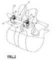
- FIG. 2is a perspective view of a “single level” spinal fixation system in use according to the present invention, including (by way of example only) first and second pedicle screws and a connecting element having dual shaped portions on either end;
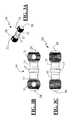
- FIGS. 3A-3Cillustrate an elongated connecting element having shaped ends for use in a single level fixation according to the present invention
- FIGS. 4A-4Cillustrate another embodiment of an elongated connecting element having shaped ends for use in a single level fixation
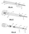
- FIG. 5illustrates a system for surgically introducing the “single level” spinal fixation system of FIG. 1 in a minimally invasive fashion, including (By way of example) a tap insulator, guide assembly (comprising a guide member and an inner sleeve), guide assembly insulator, pedicle screw driver, and a lock screw driver;
- a tap insulatorcomprising a tap insulator, guide assembly (comprising a guide member and an inner sleeve), guide assembly insulator, pedicle screw driver, and a lock screw driver;
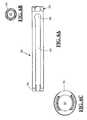
- FIGS. 6A-6Cillustrate in detail various aspects of the guide member forming part of the guide assembly according to one exemplary embodiment of the present invention
- FIG. 7A-7Eillustrate in detail various aspects of the inner sleeve forming part of the guide assembly according to one exemplary embodiment of the present invention
- FIG. 8A-8Eillustrate in detail various aspects of the pedicle screw driver according to an exemplary embodiment of the present invention
- FIGS. 9A-9Eillustrate in detail various aspects of the lock screw driver 44 according to an exemplary embodiment of the present invention.
- FIGS. 10A-10Eillustrate in detail various aspects of the tap insulator 32 according to one exemplary embodiment of the present invention
- FIGS. 11A-11Eillustrate in detail various aspects of the guide insulator 40 according to an exemplary embodiment of the present invention
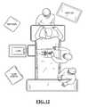
- FIG. 12is an overhead view of a first step in employing the spinal fixation system of FIG. 1 and the minimally invasive insertion system of FIG. 5 , including (by way of example), preparing the OR, placing the patient on the operating table, and making the desired incisions;
- FIG. 13illustrates a method of accessing a pedicle target site with a Jamshidi needle (and optional EMG based pedicel integrity testing) during the minimally invasive insertion of the spinal fixation system of FIG. 1 according to an exemplary embodiment of the present invention
- FIG. 14illustrates the tap insulator of FIG. 10 in use during the minimally invasive insertion of the spinal fixation system of FIG. 1 according to an exemplary embodiment of the present invention
- FIG. 15illustrates the tap insulator of FIG. 10 in combination with a tap (and optional EMG based integrity tester) during the minimally invasive insertion of the spinal fixation system of FIG. 1 according to an exemplary embodiment of the present invention
- FIGS. 16-18illustrate the method of preparing a pedicle screw and the guide assembly of FIG. 5 for minimally invasive insertion according to an exemplary embodiment of the present invention
- FIG. 19illustrates the minimally invasive insertion of the a pedicle screw using the minimally invasive insertion system of FIG. 5 according to an exemplary embodiment of the present invention
- FIG. 20is an illustration of the guide assembly after screw insertion is complete and the screw driver has been removed;
- FIG. 21illustrates a method of selecting an appropriately sized connecting element according to an exemplary embodiment of the present invention
- FIG. 22illustrates the removal of the inner sleeve members during the minimally invasive insertion of the spinal fixation system of FIG. 1 according to an exemplary embodiment of the present invention
- FIG. 23illustrates the insertion of the shaped ends of the connecting element into the guide member keyhole during the minimally invasive insertion of the spinal fixation system of FIG. 1 according to an exemplary embodiment of the present invention
- FIG. 24illustrates the significant aspect of guiding of the connecting element into the pedicle screw during the minimally invasive insertion of the spinal fixation system of FIG. 1 according to an exemplary embodiment of the present invention
- FIG. 25illustrates the method of inserting lock screws for locking the connecting element in place within the pedicle screw during the minimally invasive insertion of the spinal fixation system of FIG. 1 according to an exemplary embodiment of the present invention
- FIGS. 26-7illustrate a method of performing compression by deflecting guide members away from each other during the minimally invasive insertion of the spinal fixation system of FIG. 1 , according to an exemplary embodiment of the present invention
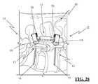
- FIG. 28illustrates the spinal fixation system of FIG. 1 after insertion using the minimally invasive insertion system of FIG. 5 , according to an exemplary embodiment of the present invention
- FIG. 29is a perspective view of a “multi level” spinal fixation system in use according to the present invention, including (by way of example only) first, second and third pedicle screws and a connecting element having dual shaped portions on either end, according to an exemplary embodiment of the present invention
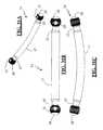
- FIGS. 30A-30Cillustrate an embodiment of an elongated connecting element having shaped ends for use in a “multi level” fixation, according to an exemplary embodiment of the present invention
- FIGS. 31A-31Cillustrate another embodiment of an elongated connecting element having shaped ends for use in a “multi level” fixation, according to an exemplary embodiment of the present invention
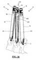
- FIG. 32illustrates a system for surgically introducing the “multi level” spinal fixation system of FIG. 29 in a minimally invasive fashion, including (By way of example) a tap insulator, guide assembly (comprising a guide member and an inner sleeve), guide assembly insulator, pedicle screw driver, and a lock screw driver, split guide member, and a counter torque tube, according to an exemplary embodiment of the present invention;
- FIGS. 33A-33Cillustrate in detail various aspects of the split guide member according to an exemplary embodiment of the present invention
- FIGS. 34A-34Cillustrate in detail the center torque tube of according to an exemplary embodiment of the present invention
- FIG. 35illustrates a guide assembly in use during minimally invasive pedicle screw insertion according to an exemplary embodiment of the present invention
- FIG. 36illustrates two guide assemblies and a center guide assembly during use during a “multi level” spinal fixation, according to an exemplary embodiment of the present invention
- FIG. 37illustrates two guide members and a split guide member after removal of sleeve members during a “multi level” spinal fixation, according to an exemplary embodiment of the present invention
- FIG. 38illustrates insertion of the connecting element through the split guide and guide members during a “multi level” spinal fixation, according to an exemplary embodiment of the present invention
- FIG. 39illustrates the use of a counter torque wrench for insertion of a lock screw during a “multi level” spinal fixation, according to an exemplary embodiment of the present invention
- FIG. 40illustrates the use of the counter torque tube during insertion of the center lock screw during a “multi level” spinal fixation, according to an exemplary embodiment of the present invention.
- FIG. 41illustrates the spinal fixation system of FIG. 1 after insertion using the minimally invasive insertion system of FIG. 5 , according to an exemplary embodiment of the present invention.
- FIGS. 1 and 2illustrate a spinal fixation system 10 according to the “single level” embodiment of the present invention.
- the spinal fixation system 10includes a pair of pedicle screw assemblies 12 and a generally elongate connecting element 14 having shaped ends 28 .
- the pedicle screw assemblies 12are poly-axial in nature, with a screw member 16 , a housing 18 , and a locking screw 20 , of the type shown and described in commonly owned and co-pending U.S. patent application Ser. No. 11/031,506 entitled “System and Method for Performing Spinal Fixation” filed Jan. 6, 2005 (“the '506 application”), the entire contents of which is hereby incorporated by reference as if set forth fully herein.
- the screw member 16 and housing 18are separate articles such that the angle of the housing 18 relative to the screw member 16 may be varied in any number of fashions prior to locking them together, hence the term “poly axial” to describe this type of pedicle screw assembly 12 according to the present invention.
- the screw member 16includes a thread 22 suitable for introduction into and purchase within bone.
- Each housing 18includes first and second branches 24 , 26 , which collectively form a generally “U-shaped” structure defining or containing an area dimensioned to receive the shaped end 28 formed either end of the connecting element 14 (according to one aspect of the present invention) and thereafter the locking screw 20 .
- each component of the poly-axial pedicle screw assembly 12is cannulated (i.e. it is equipped with a longitudinal lumen extending through the locking screw 20 and screw member 16 ) such that a K-wire may be used to guide the poly-axial pedicle screw assembly 12 into the patient according to the present invention.
- FIGS. 3A-3C and 4A-4Cillustrate various connecting elements 14 for use in the “single level” embodiment of the present invention.
- each connecting element 14includes two neck regions 15 extending between a central region 17 and the shaped ends 28 .
- the shaped ends 28are generally spherical and include an aperture or cannulation 31 capable of receiving a guide wire therethrough.
- the shaped ends 28may be partially spherical, non-cannulated, and/or comprise any form or shape capable of being disposed wholly within the housing 18 of the pedicle screw assembly 12 , including but not limited to the generally spherical shape shown and described herein and in the '506 application, as well as the non-spherical shaped ends disclosed in commonly owned and co-pending U.S. patent application Ser. No. 10/894,533 (“the '533 application”), the entire contents of which are incorporated by reference as if set forth fully herein.
- Connecting element 14may be provided having any of a range of suitable dimensions to accommodate the anatomical and pathologic considerations of the given patient for a single level application, including but not limited to a length (including the shaped ends 28 ) ranging from 15 mm to 25 mm. Although shown as generally straight, it will be appreciated that the connecting element 14 may be curved slightly (particularly for the larger sizes) to better accommodate the natural curvature of the spine over a single level.
- the feature of providing shaped ends 28 on the connecting element 14avoids the “overhang” prevalent with prior art pedicle systems which employ straight rods as connecting elements (without shaped ends).
- This featureis also advantageous in that it provides the ability to rotate the housing 18 of the poly-axial pedicle screw assemblies 12 about the shaped end 28 to accomplish “instrument free” compression and/or distraction via the use of the introduction devices forming part of the present invention (described below) as opposed to separate and distinct compression and/or distraction instruments.
- Thisit will be appreciated, saves valuable operative time in eliminating the use of dedicated compression and/or distraction tools, as well as the associated cost of manufacturing and providing such dedicated compression and/or distraction instruments.
- FIG. 5illustrates a minimally disruptive introduction system 30 for introducing the spinal fixation system 10 according to the “single level” embodiment of the present invention.
- the introduction system 30includes (by way of example only) a tap insulator 32 , a guide assembly 34 (comprising a guide member 36 and an inner sleeve 38 ), a guide assembly insulator 40 , a pedicle screw driver 42 , and a lock screw driver 44 .
- the introduction system 30may also include a spinal access needle for accessing a pedicle target site (e.g. Jamshidi needle), a guide wire (e.g.
- K-wirefor placement through the spinal access needle and creating an initial hole in the pedicle target site
- a guide wire insulatorfor insulating the guide wire during optional EMG-based pedicle integrity testing during the guide wire introduction process
- a cannulated tapfor advancement over the guide wire to prepare a tapped pilot hole.
- the guide assembly 34is dimensioned to introduce (as a first step) each pedicle screw 12 into a target pedicle site—preferably with the assistance of the pedicle screw driver 42 —and (as a second step) guide the shaped ends 28 of the connecting element 14 into the receiving area of the pedicle screw housing 18 .
- the locking element driver 44may be employed to secure the locking element 20 within the pedicle screw housing 18 to thereby lock the connecting element 14 to the pedicle screw assembly 12 .
- the tap insulator 32 and guide assembly insulator 40may be employed during optional EMG-based pedicle integrity testing, such as shown and described in commonly owned and co-pending U.S. patent application Ser. No.
- FIGS. 6A-6Cillustrate in detail various aspects of the guide member 36 forming part of the guide assembly 34 according to an exemplary embodiment of the present invention.
- Guide member 36has a generally elongated cylindrical shape with a length sufficient to extend from a pedicle target site at a distal end 56 , to a position outside the surgical corridor at a proximal end 58 , as best viewed in FIG. 20 .
- An interior lumen 60extends from distal end 56 to proximal end 58 .
- the guide member 36includes a guide channel 64 having an enlarged keyhole opening 66 at a proximal end and an open distal end.
- the guide channel 64passes into the interior lumen 60 and extends substantially along the guide from distal end 56 to a position short of proximal end 58 .
- the keyhole opening 66is dimensioned to receive the shaped end 28 of connecting element 14 such that the shaped end 28 will be disposed within the interior lumen 60 .
- the neck portion 15 of the connecting element 14may pass through the guide channel 64 such that the shaped ends 28 may be advanced into engagement within the pedicle screw housing 18 .
- the shaped end 28is provided having a diameter that is larger than the width of the guide channel 64 , such that the shaped end 28 is retained within the interior lumen 60 during this process.
- Guide member 36preferably comprises a surgical grade metal such as, by way of example, stainless steel, aluminum and/or titanium, although other biologically suitable compositions (such as, by way of example, plastics, ceramics, and/or carbon composites) may be employed as well.
- the guide member 36may be provided having any number of suitable dimensions to accommodate the anatomical and pathologic considerations of the given patient, including but not limited to a length ranging from 4 to 6 inches.
- FIGS. 7A-7Eillustrate in detail various aspects of the inner sleeve member 38 forming part of the guide assembly 34 according to an exemplary embodiment of the present invention.
- Inner sleeve member 38has a generally elongated cylinder shape with a distal end 68 , a proximal end 70 , and a center region 72 .
- Distal end 68includes a threaded region 74 for engaging a corresponding threaded region within screw housing 18 of pedicle screw 12 , thereby coupling pedicle screw 12 to the guide assembly for insertion into the pedicle target site.
- Center region 72is dimensioned to extend through interior lumen 60 of guide member 36 such that distal end 68 may engage with screw housing 18 when fully inserted.
- Proximal end 70has a circumference generally greater than center region 72 and may not pass into interior lumen 60 of guide member 36 .
- Proximal end 70may also include knurling to increase operator control.
- Inner sleeve 38also includes an interior lumen 76 extending from distal end 68 to proximal end 70 and dimensioned to receive the pedicle screw driver 42 for the purpose of tightening the pedicle screw assembly 12 prior to introducing the shaped end 28 of the connecting element 14 into the housing 18 .
- FIGS. 8A-8Eillustrate in detail various aspects of the pedicle screw driver 42 according to an exemplary embodiment of the present invention.
- Screw driver 42is dimensioned to be inserted through the inner sleeve member 38 of guide assembly 34 .
- a distal end 84( FIGS. 8D-8E ) is configured to engage screw member 16 of pedicle screw 12 .
- a proximal end 86( FIGS. 8B-8C ) is configured to engage and attach to any of a variety of suitable handles.
- Pedicle screw driver 42may preferably include an interior lumen 88 ( FIG. 8D-8E ) extending from distal end 84 to proximal end 86 to allow insertion over a guide wire (not shown).
- FIGS. 9A-9Eillustrate in detail various aspects of the lock screw driver 44 according to an exemplary embodiment of the present invention.
- Lock screw driver 44is dimensioned to be inserted through the interior lumen 60 of guide member 36 .
- a distal end 90( FIGS. 9D-9E ) is configured to engage a receiving area within the lock screw 20 of spinal fixation system 10 .
- a proximal end 92( FIGS. 9B-9C ) is configured to engage and attach to any of a variety of suitable handles.
- FIGS. 10A-10Eillustrate in detail various aspects of the tap insulator 32 according to one exemplary embodiment of the present invention.
- Tap insulator 32has a generally elongated cylinder shape with a length sufficient to extend from a vertebral pedicle at a distal end 50 , to a position outside the surgical corridor at a proximal end 52 , as best viewed in FIGS. 14-15 .
- the tap insulator 32is provided with an interior lumen 54 ( FIGS. 10B, 10E ) extending from the distal end 50 to the proximal end 52 , which is dimensioned to allow passage of a tap (preferably cannulated) to a pedicle target site.
- Tap insulator 32is designed to insulate tissue from electrical signals passed through the tap (not shown) during optional EMG-based pedicle integrity testing during tapping, as set forth in greater detail in the NeuroVision Applications. Tap insulator 32 accomplishes this by being constructed of any number of suitable non-conductive materials, including but not limited to a durable plastic such as, by way of example, Raedel, and/or surgical grade metal (such as, by way of example, aluminum or titanium) with an insulating coating.
- the tap insulator 32may be provided having any number of suitable dimensions to accommodate the anatomical and pathologic considerations of the given patient, including but not limited to a length ranging from 4 to 7 inches.
- Distal end 50( FIG. 10D ) may be tapered to minimize tissue impaction during insertion and proximal end 52 ( FIG. 10C ) may include knurling to increase operator control over the instrument.
- FIGS. 11A-11Eillustrate in detail various aspects of the guide insulator 40 according to an exemplary embodiment of the present invention.
- Guide insulator 40has a generally elongated cylinder shape with a length sufficient to extend from a vertebral pedicle at a distal end 78 , to a position outside the surgical corridor at a proximal end 80 , as best viewed in FIG. 19 .
- Guide insulator 40is provided with an interior lumen 82 ( FIGS. 11B, 11E ) extending from distal end 78 to proximal end 80 .
- the lumen 82is dimensioned to allow guide assembly 34 to extend through to the pedicle target site and to allow guide insulator 40 to be passed over the exterior surface of tap insulator 32 to the pedicle target site.
- Guide insulator 40is designed to insulate tissue from electrical signals passed through the driver and pedicle screw (not shown) during optional EMG-based pedicle integrity testing during screw placement, as set forth in greater detail in the NeuroVision Applications.
- Guide insulator 40accomplishes this by being constructed of any number of suitable non-conductive materials, including but not limited to a durable plastic such as, by way of example, Raedel, and/or surgical grade metal (such as, by way of example, aluminum or titanium) with an insulating coating.
- the guide insulator 40may be provided having any number of suitable dimensions to accommodate the anatomical and pathologic considerations of the given patient, including but not limited to a length ranging from 4 to 7 inches.
- Proximal end 80may include knurling to increase operator control over the instrument.
- a first stepinvolves placing a patient on an operating table, preferably in the prone position, and thereafter making small incisions over the desired vertebra.
- a pedicle target sitemay then be accessed and a pilot hole formed using a spinal access needle 95 (ie. Jamshidi needle), as shown in FIG. 13 .
- Optional EMG-based pedicle integrity testingmay be performed at this stage by coupling a non-insulated portion of the spinal access needle 95 to a clip 97 to establish electrical communication with a neuromonitoring system of the type in the NeuroVision Applications.
- the spinal access needle 95is preferably insulated along the shaft such that the electrical signals selectively transmitted to the spinal access needle via the neuromonitoring system are transmitted at or near the distal end of the access needle 95 . This avoids shunting the electrical signals into the tissue of the patient, and focuses the electrical stimulation at the working end of the spinal access needle 95 . If the spinal access needle 95 breaches the pedicle, the electrical stimulation will transmit through the hole or breach and stimulate adjacent neural elements. By monitoring the degree of this evoked response, the surgeon may assess if the integrity of the pedicle has been breached during pilot hole formation.
- a guide wire 94(e.g. K-wire) may then be inserted into the pedicle through a cannulation formed in the pedicle access needle 95 .
- the pedicle access needle 95may thereafter be carefully removed such that only the K-wire 94 remains in the pilot hole.
- a K-wire insulator 96(of the type disclosed in the NeuroVision Applications) may be inserted over the K-wire 94 and then the tap insulator 32 may be inserted over the K-wire insulator 96 , both while performing optional EMG-based pedicle integrity testing as described in the NeuroVision Applications.
- the next stepinvolves tapping the previously formed pilot hole.
- a cannulated tap 98is inserted over the K-wire 94 and through the tap insulator 32 to the pedicle target site.
- the pilot holemay then be tapped while performing optional EMG-based pedicle integrity testing as described in the NeuroVision Applications in order to detect any breach in the pedicle caused during the tapping process. If the pedicle integrity assessment is positive (meaning a high stimulation threshold), then pilot hole preparation may be considered complete and the tap 98 removed from the tap insulator 32 . This procedure may be repeated to prepare a pilot hole for each pedicle in which a pedicle screw assembly 12 will be placed.
- FIGS. 16-18illustrate the method of preparing a pedicle screw assembly 12 and the guide assembly 34 for use in pedicle screw placement according to one embodiment of the present invention.
- the screw housing 18 of pedicle screw assembly 12is inserted into the distal end of guide member 36 as shown in FIG. 16 .
- the next step, shown in FIG. 17involves inserting inner sleeve member 38 through the guide member 36 such that the threaded region 74 of inner sleeve member 38 is engaged with a corresponding threaded region in screw housing 18 .
- FIG. 17illustrates the method of preparing a pedicle screw assembly 12 and the guide assembly 34 for use in pedicle screw placement according to one embodiment of the present invention.
- the screw housing 18 of pedicle screw assembly 12is inserted into the distal end of guide member 36 as shown in FIG. 16 .
- the next step, shown in FIG. 17involves inserting inner sleeve member 38 through the guide member 36 such that the threaded region 74 of inner sleeve
- the pedicle screw driver 42is then inserted through the inner sleeve member 38 and engaged into a receiving area within the proximal end of the screw member 16 of pedicle screw assembly 12 .
- the surgeonmay undertake to place the pedicle screw assembly 12 into a pedicle according to the present invention.
- the guide insulator 40is first inserted to the pedicle target site over the tap insulator 32 . With the guide insulator 40 in place, the tap insulator 32 (and tap 98 , if still present inside the insulator 32 ) may then be removed. The guide assembly 34 with the pedicle screw assembly 12 coupled thereto may then be placed over the K-wire 94 and inserted to the pedicle target site through the guide insulator 40 , illustrated in FIG. 19 , preferably while performing optional EMG-based pedicle integrity testing as described in the NeuroVision Applications to monitor for potential pedicle breaches during screw placement.
- the pedicle screw driver 42 and guide insulator 40may be removed so as to leave only the guide assembly 34 in place, as shown in FIG. 20 . This process may be repeated for each pedicle screw assembly 12 to be placed.
- the surgeonmay then select a connecting element 14 of appropriate size.
- the connecting element 14may be selected by matching it to the length of the guide assemblies 34 after they have been brought into a generally parallel arrangement as shown. Slightly longer or slightly shorter connecting elements 14 may be selected based the experience and particular needs of the surgeon. By way of example only, a longer connecting element 14 may be selected if extra distraction is desired and/or a shorter connecting element 14 may be selected if extra compression is desired.
- the inner sleeve members 38may then be unthreaded from each screw housing 18 and removed from the guide member 36 as shown in FIG. 22 , taking care not to dislodge the guide member 36 from the screw housing 18 .
- the shaped ends 28 of the connecting element 14may then be inserted into the keyhole 66 on each guide member 36 , as seen in FIG. 23 .
- the connecting element 14may be urged downwards within the guide channels 64 of the guide member 36 , through the minimally disruptive incision created between the adjacent guide members 36 (between the patient's skin and the approximate pedicle target site), until the shaped ends 28 are positioned within the correspondingly shaped receiving areas within the pedicle screw housing 18 .
- a pushing instrument(not shown) may be used to push the connecting element 14 down the guide member 36 .
- the lock screws 20 of the spinal fixation system 10may then be advanced through the guide member 36 and locked over the shaped ends 28 of the connecting element 14 via the lock screw driver 44 . If distraction or compression is desired, the lock screws 20 may be tightened until snug and then backed off slightly. According to important aspects of the present invention, “instrument free” distraction may be achieved simply be deflecting the guide members 36 toward each other (as in FIG. 25 ) and retightening the lock screws 20 , while “instrument free” compression may be accomplished by deflecting the guide members 36 away from each other (as in FIG. 26-27 ).
- instrument freeis used herein to mean that the present invention can accomplish desired compression and/or distraction without the need for separate, dedicated compression and/or distraction instruments. This, it will be appreciated, is advantageous in that it saves valuable operative time by not causing the surgeon to switch instruments in order to perform compression and/or distraction, and also saves manufacturing costs via the elimination of the otherwise dedicated compression and/or distraction instruments.
- a counter torque wrench 46may be applied to the proximal end of the guide member 36 to facilitate the final tightening of the lock screws 20 .
- the guide members 36may then be removed, which results in the final implanted “single level” spinal fixation system 10 as shown in FIG. 28 .
- the proceduremay be repeated on the contralateral side to achieve greater fixation.
- the proceduremay also be carried out simultaneously on both sides if desired.
- the spinal fixation system 10 of the present inventionvia the use of the introduction system 30 of the present invention, advantageously accomplishes minimally disruptive spinal fixation between adjacent vertebral bodies.
- FIG. 29illustrates the spinal fixation system 10 according to the “multi-level” embodiment of the present invention, meaning it spans at least three vertebrae (e.g. two vertebral levels).
- the spinal fixation system 10accomplishes this, by way of example only, via the use of at least three pedicle screw assemblies 12 implanted in adjacent pedicles along the spine and by providing the connecting element 14 having length and configuration sufficient to be coupled to each pedicle screw assembly 12 .
- the pedicle screw assemblies 12 employed in the multi-level embodimentare identical in construction as shown and described above with reference to the single level embodiment, such that a repeat discussion of the common elements is unnecessary.
- FIGS. 30A-30C and 31A-31Cillustrate various connecting elements 14 for use in the “multi-level” embodiment of the present invention.
- the main distinction from the “single level” embodimentis that the connecting elements 14 are preferably slightly curved in nature so as to better accommodate the natural curvature of the spine over multiple vertebral levels.
- the “multi-level” connecting elements 14may be provided having any of a range of suitable dimensions to accommodate the anatomical and pathologic considerations of the given patient for multi-level applications, including but not limited to a length (including the shaped ends 28 ) ranging from 25 mm to 70 mm.
- the connecting elements 14 in the multi-level embodimentmay be provided as generally straight if desired.
- the connecting elements 14 of the multi-level embodimentare identical in construction to those shown and described above with reference to the single level embodiment, such that a repeat discussion of the common elements is unnecessary.
- the shaped ends 28 on the connecting element 14provide the same advantages described with reference to the single level embodiment, namely it avoids the “overhang” prevalent with prior art pedicle systems which employ straight rods as connecting elements (without shaped ends), and provides the ability to rotate the housing of the poly-axial pedicle screw assemblies 12 about the shaped end 28 to accomplish “instrument free” compression and/or distraction via the use of the guide members 36 of the minimally disruptive introduction system 30 of the present invention.
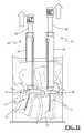
- FIG. 32illustrates the minimally disruptive introduction system 30 for introducing the spinal fixation system 10 according to the “multi-level” embodiment of the present invention.
- the introduction system 30includes a spilt guide member 360 and a counter torque tube 365 in addition to the instruments shown and described above with reference to the “single level” embodiment.
- the split guide member 360When coupled together with the inner sleeve 38 (as will be described below), the split guide member 360 comprises a center guide assembly 340 .
- the introduction system 30 of the multi-level embodimentis identical in construction to that shown and described above with reference to the single level embodiment, such that a repeat discussion of the common elements is unnecessary.
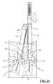
- FIGS. 33A-33Cillustrate in detail various aspects of the split guide member 360 according to an exemplary embodiment of the present invention.
- Split guide member 360has a generally elongated cylindrical shape with a length sufficient to extend from a pedicle target site at a distal end 560 , to a position outside the surgical corridor at a proximal end 580 , as best viewed in FIG. 39 .
- An interior lumen 600extends from distal end 560 to proximal end 580 .
- the split guide member 360includes a guide channel 640 having an enlarged keyhole opening 660 at a proximal end and an open distal end.
- two guide channels 640are located on split guide member 360 approximately 180 degrees from one another.
- Guide channels 640pass into the interior lumen 600 and extend substantially along the split guide member 360 from distal end 560 to a position short of proximal end 580 .
- the proximal ends of guide channels 640comprise keyholes 660 dimensioned to receive the shaped end 28 of the multi-level connecting element 14 . More specifically, the shaped end 28 on one end of the connecting element 14 is preferably passed though the keyhole 660 on one side of the split guide member 360 and then through the keyhole 660 on the other side of the split guide member 360 such that the central section 17 of the connecting element 14 may thereafter be passed downward through the guide channel 640 .
- the split guide 360also includes two longitudinal grooves 645 positioned approximately ninety (90) degrees from the guide channels 640 and extending from the proximal end 580 to a point short of the distal end distal end 560 . As will be discussed below, grooves 645 mate with interior ridges 395 provided on the counter torque tube 365 .
- Split guide member 360preferably comprises a surgical grade metal such as, by way of example, stainless steel, aluminum and/or titanium, although other biologically suitable compositions (such as, by way of example, plastics, ceramics, and/or carbon composites) may be employed as well.
- the split guide member 360may be provided having any number of suitable dimensions to accommodate the anatomical and pathologic considerations of the given patient, including but not limited to a length ranging from 4 to 6 inches.
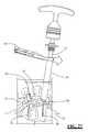
- FIGS. 34A-34Cillustrate in detail the center torque tube 365 of the system 30 according to an exemplary embodiment of the present invention.
- Counter torque tube 365comprises a handle 375 and a generally elongate tube 385 .
- the handle 375may be fixedly or detachably coupled to the elongate tube 385 .
- Tube 385has a generally elongated cylinder shape with a length matching approximately that of the spilt guide member 360 , as shown in FIG. 40 .
- the tube 385includes a lumen 387 extending between a distal end to a proximal end with one or more ridges 395 disposed along the interior of the lumen 387 .
- the ridges 395are preferably disposed generally parallel to the central longitudinal axis of the tube 385 .
- the ridges 395may be provided with any suitable length, such as the approximate length of the grooves 645 of the split guide member 360 or any length short of that so long as it's sufficient to adequately engage the grooves 645 to prevent the unwanted rotation of the split guide member 360 when tightening the lock screws 20 .
- the distal end of the tube 385may also be equipped with a pair of recesses 389 located approximately ninety (90) degrees from one another and dimensioned to accommodate the central portion 17 of the connecting element 14 as shown in FIG. 40 .
- Tube 385preferably comprises a surgical grade metal such as, by way of example, stainless steel, aluminum and/or titanium, although other biologically suitable compositions (such as, by way of example, plastics, ceramics, and/or carbon composites) may be employed as well.
- the tube 385may be provided having any number of suitable dimensions to accommodate the anatomical and pathologic considerations of the given patient, including but not limited to a length ranging from 4 to 6 inches.
- the handle 375may be any number of suitable lengths and dimensions to provide the surgeon with a sufficient purchase on the tube 385 during use.
- the spinal fixation system 10 and minimally disruptive introduction system 30 of the “multi-level” embodiment of the present invention systemmay be employed as follows (with common steps from the “single level” embodiment selectively omitted as unnecessary).
- Pedicle target sitesare accessed and pilot holes are formed and tapped according to the procedure described above with reference to FIGS. 13-15 .
- Coupling the pedicle screw assemblies 12 to the guide assemblies 34may then be carried out as described above with reference to FIGS. 16-18 .
- an additional pedicle screw assembly 12may be coupled to a center guide assembly 340 ( FIG. 32 ) by substituting the guide member 36 for the split guide member 360 in the process described above with reference to FIGS. 16-18 .
- the spinal fixation system 10 and introduction system 30 of the “multi-level” embodimentmay be introduced in the same minimally disruptive manner with the same benefits described in detail above.
- the guide insulator 40 and guide assembly 34are introduced into one of the superior or inferior pedicle target sites, as described above with reference to FIG. 19 .
- FIG. 35the guide insulator 40 and guide assembly 34 are introduced into one of the superior or inferior pedicle target sites, as described above with reference to FIG. 19 .
- the center guide assembly 340should then be positioned over a centrally located vertebra (such as the middle vertebra shown in the two level example shown by way of example) and the central pedicle screw assembly 12 introduced in the same manner as the superior and inferior pedicle screw assemblies 12 as described above with reference to FIGS. 19-20 .
- a centrally located vertebrasuch as the middle vertebra shown in the two level example shown by way of example
- the central pedicle screw assembly 12introduced in the same manner as the superior and inferior pedicle screw assemblies 12 as described above with reference to FIGS. 19-20 .
- An appropriately sized connecting element 14may be selected based on the experience and particular needs of the surgeon and patient anatomy, including but not limited to the manner described above with reference to FIG. 21 (using the guide assemblies 34 ).
- the inner sleeve members 38may be unthreaded and removed from the guide assemblies 34 and 340 , as shown in FIG. 37 , taking care not to dislodge the guide members 36 and/or split guide member 360 from screw housings 18 .
- the connecting element 14may then be inserted through the split guide member 360 utilizing the keyholes 660 as described above with reference to FIGS. 33A-33C .
- the shaped ends 28are then inserted into the superior and inferior guide members 36 by way of keyholes 66 as described above with reference to FIG. 23 .
- the connecting element 14may then be advanced downwards into the guide channels 64 and 640 of the respective guide members 36 , 360 such that the shaped ends 28 are disposed within the superior and inferior pedicle screw housings 18 as described above with reference to FIG. 24 and the central portion 17 is disposed within the central pedicle screw housing 18 as shown in FIG. 38 .
- a rod pusher or rod clamp 102may be used to push connecting element 14 down the guide members 36 and split guide member 360 , as pictured in FIG. 38 .
- FIG. 39illustrates the step of inserting lock screws 20 through the guide members 36 and split guide 360 using the lock screw driver 44 .
- the lock screws 20may be tightened until snug and then backed off slightly.
- Distractionmay be achieved in a preferred method by tightening the center lock screw 20 as shown in FIG. 40 and deflecting the guide members 36 toward each other as described above with reference to FIG. 25 .
- Compressionmay be achieved in a preferred method by tightening the center lock screw 20 as shown in FIG. 40 and deflecting the guide members 36 away from each other as described above with reference to FIGS. 26-27 .
- the central lock screws 20are preferably tightened by utilizing the counter torque tube 365 .
- the counter torque tube 365is inserted over the split guide member 360 such that its interior ridges 395 mate with the grooves 645 of guide 360 , thereby preventing rotational movement as torque is applied to the lock screws 20 until a final locked position is achieved.
- a counter torque wrench 46may be applied to the superior and/or inferior guide members 36 to facilitate the final tightening of the superior and/or inferior lock screws 20 .
- the guide member 36 and split guide member 360are removed and multilevel fixation is complete. If desired the procedure may be repeated on the contralateral side to achieve greater fixation. Alternatively, the procedure may be carried out simultaneously on both sides.
Landscapes
- Health & Medical Sciences (AREA)
- Orthopedic Medicine & Surgery (AREA)
- Neurology (AREA)
- Life Sciences & Earth Sciences (AREA)
- Surgery (AREA)
- Heart & Thoracic Surgery (AREA)
- Engineering & Computer Science (AREA)
- Biomedical Technology (AREA)
- Nuclear Medicine, Radiotherapy & Molecular Imaging (AREA)
- Medical Informatics (AREA)
- Molecular Biology (AREA)
- Animal Behavior & Ethology (AREA)
- General Health & Medical Sciences (AREA)
- Public Health (AREA)
- Veterinary Medicine (AREA)
- Surgical Instruments (AREA)
Abstract
Description
Claims (36)
Priority Applications (1)
| Application Number | Priority Date | Filing Date | Title |
|---|---|---|---|
| US11/667,365US9737339B2 (en) | 2004-09-08 | 2005-09-08 | Posterio spinal fixation |
Applications Claiming Priority (3)
| Application Number | Priority Date | Filing Date | Title |
|---|---|---|---|
| US60847604P | 2004-09-08 | 2004-09-08 | |
| PCT/US2005/032300WO2006029373A1 (en) | 2004-09-08 | 2005-09-08 | Systems and methods for performing spinal fixation |
| US11/667,365US9737339B2 (en) | 2004-09-08 | 2005-09-08 | Posterio spinal fixation |
Publications (2)
| Publication Number | Publication Date |
|---|---|
| US20080183214A1 US20080183214A1 (en) | 2008-07-31 |
| US9737339B2true US9737339B2 (en) | 2017-08-22 |
Family
ID=36036700
Family Applications (1)
| Application Number | Title | Priority Date | Filing Date |
|---|---|---|---|
| US11/667,365Active2031-07-21US9737339B2 (en) | 2004-09-08 | 2005-09-08 | Posterio spinal fixation |
Country Status (3)
| Country | Link |
|---|---|
| US (1) | US9737339B2 (en) |
| EP (1) | EP1814472B1 (en) |
| WO (1) | WO2006029373A1 (en) |
Cited By (13)
| Publication number | Priority date | Publication date | Assignee | Title |
|---|---|---|---|---|
| US10653454B2 (en) | 2007-07-13 | 2020-05-19 | Mighty Oak Medical, Inc. | Spinal fixation systems |
| US10743890B2 (en) | 2016-08-11 | 2020-08-18 | Mighty Oak Medical, Inc. | Drill apparatus and surgical fixation devices and methods for using the same |
| USD895111S1 (en) | 2018-06-04 | 2020-09-01 | Mighty Oak Medical, Inc. | Sacro-iliac guide |
| US10898240B2 (en) | 2016-11-18 | 2021-01-26 | Jgmg Bengochea, Llc | Implants and instruments for enhancing vertebral alignment and sagittal balance |
| US11039889B2 (en) | 2010-06-29 | 2021-06-22 | Mighty Oak Medical, Inc. | Patient-matched apparatus and methods for performing surgical procedures |
| USD948717S1 (en) | 2018-06-04 | 2022-04-12 | Mighty Oak Medical, Inc. | Sacro-iliac guide |
| US11376073B2 (en) | 2010-06-29 | 2022-07-05 | Mighty Oak Medical Inc. | Patient-matched apparatus and methods for performing surgical procedures |
| US11583318B2 (en) | 2018-12-21 | 2023-02-21 | Paradigm Spine, Llc | Modular spine stabilization system and associated instruments |
| US11633254B2 (en) | 2018-06-04 | 2023-04-25 | Mighty Oak Medical, Inc. | Patient-matched apparatus for use in augmented reality assisted surgical procedures and methods for using the same |
| US11806197B2 (en) | 2010-06-29 | 2023-11-07 | Mighty Oak Medical, Inc. | Patient-matched apparatus for use in spine related surgical procedures and methods for using the same |
| US12016573B2 (en) | 2016-08-11 | 2024-06-25 | Mighty Oak Medical, Inc. | Drill apparatus and surgical fixation devices and methods for using the same |
| US12357413B2 (en) | 2010-06-29 | 2025-07-15 | Mighty Oak Medical, Inc. | Patient-matched apparatus for use in spine related surgical procedures and methods for using the same |
| US12440276B2 (en) | 2024-03-14 | 2025-10-14 | Mighty Oak Medical, Inc. | Systems and methods for presurgical planning |
Families Citing this family (72)
| Publication number | Priority date | Publication date | Assignee | Title |
|---|---|---|---|---|
| US8353932B2 (en)* | 2005-09-30 | 2013-01-15 | Jackson Roger P | Polyaxial bone anchor assembly with one-piece closure, pressure insert and plastic elongate member |
| EP1417000B1 (en) | 2001-07-11 | 2018-07-11 | Nuvasive, Inc. | System for determining nerve proximity during surgery |
| JP2005503857A (en) | 2001-09-25 | 2005-02-10 | ヌバシブ, インコーポレイテッド | Systems and methods for performing surgical procedures and surgical diagnosis |
| US20100168751A1 (en)* | 2002-03-19 | 2010-07-01 | Anderson D Greg | Method, Implant & Instruments for Percutaneous Expansion of the Spinal Canal |
| US7582058B1 (en) | 2002-06-26 | 2009-09-01 | Nuvasive, Inc. | Surgical access system and related methods |
| US8137284B2 (en) | 2002-10-08 | 2012-03-20 | Nuvasive, Inc. | Surgical access system and related methods |
| US7691057B2 (en) | 2003-01-16 | 2010-04-06 | Nuvasive, Inc. | Surgical access system and related methods |
| US7905840B2 (en) | 2003-10-17 | 2011-03-15 | Nuvasive, Inc. | Surgical access system and related methods |
| JP4463819B2 (en) | 2003-09-25 | 2010-05-19 | ヌヴァシヴ インコーポレイテッド | Surgical access system |
| US9055934B2 (en)* | 2004-08-26 | 2015-06-16 | Zimmer Spine, Inc. | Methods and apparatus for access to and/or treatment of the spine |
| US7547318B2 (en)* | 2004-03-19 | 2009-06-16 | Depuy Spine, Inc. | Spinal fixation element and methods |
| US7927356B2 (en)* | 2006-07-07 | 2011-04-19 | Warsaw Orthopedic, Inc. | Dynamic constructs for spinal stabilization |
| US7806913B2 (en) | 2006-08-16 | 2010-10-05 | Depuy Spine, Inc. | Modular multi-level spine stabilization system and method |
| US7686809B2 (en) | 2006-09-25 | 2010-03-30 | Stryker Spine | Rod inserter and rod with reduced diameter end |
| US7998144B2 (en) | 2006-12-22 | 2011-08-16 | Aesculap Ag | Surgical instrument and osteosynthesis device |
| US7922731B2 (en) | 2006-12-22 | 2011-04-12 | Aesculap Ag | Surgical instrument and osteosynthesis device |
| US20080161853A1 (en) | 2006-12-28 | 2008-07-03 | Depuy Spine, Inc. | Spine stabilization system with dynamic screw |
| EP2047812B1 (en)* | 2007-10-11 | 2011-12-14 | BIEDERMANN MOTECH GmbH | Bone anchoring device |
| US9060813B1 (en) | 2008-02-29 | 2015-06-23 | Nuvasive, Inc. | Surgical fixation system and related methods |
| US20100004693A1 (en)* | 2008-07-01 | 2010-01-07 | Peter Thomas Miller | Cam locking spine stabilization system and method |
| US8118837B2 (en)* | 2008-07-03 | 2012-02-21 | Zimmer Spine, Inc. | Tapered-lock spinal rod connectors and methods for use |
| US8197512B1 (en)* | 2008-07-16 | 2012-06-12 | Zimmer Spine, Inc. | System and method for spine stabilization using resilient inserts |
| US8167914B1 (en) | 2008-07-16 | 2012-05-01 | Zimmer Spine, Inc. | Locking insert for spine stabilization and method of use |
| EP2153786B1 (en) | 2008-08-12 | 2011-10-26 | BIEDERMANN MOTECH GmbH | Modular system for the stabilization of the spinal column |
| EP2378981B1 (en)* | 2008-08-18 | 2018-09-26 | Retrospine Pty Ltd. | Retractor blade and assembly for spinal surgery |
| US8876869B1 (en)* | 2009-06-19 | 2014-11-04 | Nuvasive, Inc. | Polyaxial bone screw assembly |
| US8506598B1 (en) | 2009-06-26 | 2013-08-13 | Nuvasive, Inc. | Anchors for spinal fixation and correcting spinal deformity |
| USD642268S1 (en)* | 2009-08-26 | 2011-07-26 | Theken Spine, Llc | Hex rod for spinal surgery |
| DE112010004338B4 (en) | 2009-11-10 | 2019-06-27 | Nuvasive, Inc. | DEVICE FOR IMPLEMENTING SPINE SURGERY |
| WO2011126825A2 (en)* | 2010-03-29 | 2011-10-13 | Anderson D Greg | Device and method for expanding the spinal canal with spinal column stabilization and spinal deformity correction |
| WO2017066518A1 (en) | 2010-06-29 | 2017-04-20 | Mighty Oak Medical, Inc. | Patient-matched apparatus and methods for performing surgical procedures |
| KR101859932B1 (en) | 2010-06-29 | 2018-05-21 | 조지 프레이 | Patient matching surgical guide and method for using the same |
| US9642633B2 (en) | 2010-06-29 | 2017-05-09 | Mighty Oak Medical, Inc. | Patient-matched apparatus and methods for performing surgical procedures |
| US8870889B2 (en) | 2010-06-29 | 2014-10-28 | George Frey | Patient matching surgical guide and method for using the same |
| CN109171845B (en) | 2010-08-23 | 2021-04-13 | 纽文思公司 | Retractor Assembly |
| US9198692B1 (en) | 2011-02-10 | 2015-12-01 | Nuvasive, Inc. | Spinal fixation anchor |
| US9387013B1 (en) | 2011-03-01 | 2016-07-12 | Nuvasive, Inc. | Posterior cervical fixation system |
| WO2012127268A1 (en)* | 2011-03-18 | 2012-09-27 | Scient'x | A fitting tool for a pedicular anchoring system |
| US20160270802A1 (en)* | 2011-03-25 | 2016-09-22 | National Cheng Kung University | Guiding element for spinal drilling operation and guiding assembly comprising the same |
| US20120245587A1 (en)* | 2011-03-25 | 2012-09-27 | Jing-Jing Fang | Method for spinal drilling operation and guiding assembly |
| US8790406B1 (en) | 2011-04-01 | 2014-07-29 | William D. Smith | Systems and methods for performing spine surgery |
| US9907582B1 (en) | 2011-04-25 | 2018-03-06 | Nuvasive, Inc. | Minimally invasive spinal fixation system and related methods |
| US9307972B2 (en) | 2011-05-10 | 2016-04-12 | Nuvasive, Inc. | Method and apparatus for performing spinal fusion surgery |
| USD738498S1 (en) | 2013-12-16 | 2015-09-08 | George Frey | Sacroiliac surgical guide |
| USD705929S1 (en) | 2011-06-29 | 2014-05-27 | George A. Frey | Surgical guide |
| USD745672S1 (en) | 2012-09-18 | 2015-12-15 | George Frey | Thoracic surgical guide |
| USD672038S1 (en) | 2011-06-29 | 2012-12-04 | George Frey | Surgical guide |
| USD775335S1 (en) | 2011-06-29 | 2016-12-27 | Mighty Oak Medical, Inc. | Multi-level surgical guide |
| US9622779B2 (en) | 2011-10-27 | 2017-04-18 | DePuy Synthes Products, Inc. | Method and devices for a sub-splenius / supra-levator scapulae surgical access technique |
| US9655505B1 (en) | 2012-02-06 | 2017-05-23 | Nuvasive, Inc. | Systems and methods for performing neurophysiologic monitoring during spine surgery |
| US9066701B1 (en) | 2012-02-06 | 2015-06-30 | Nuvasive, Inc. | Systems and methods for performing neurophysiologic monitoring during spine surgery |
| US20150342621A1 (en)* | 2014-05-29 | 2015-12-03 | Avery M. Jackson, III | Illuminated endoscopic pedicle probe with dynamic real time monitoring for proximity to nerves |
| US20140142420A1 (en) | 2012-05-16 | 2014-05-22 | Avery M. Jackson, III | Illuminated Endoscopic Pedicle Probe With Replaceable Tip |
| USD745673S1 (en) | 2012-09-18 | 2015-12-15 | George Frey | Lumbar surgical guide |
| USD745671S1 (en) | 2012-09-18 | 2015-12-15 | George Frey | Transitional surgical guide |
| US9757067B1 (en) | 2012-11-09 | 2017-09-12 | Nuvasive, Inc. | Systems and methods for performing neurophysiologic monitoring during spine surgery |
| JP6259513B2 (en) | 2013-06-07 | 2018-01-10 | フライ, ジョージFREY, George | Patient-compatible instruments and methods for performing surgical procedures |
| US9517089B1 (en) | 2013-10-08 | 2016-12-13 | Nuvasive, Inc. | Bone anchor with offset rod connector |
| US9744050B1 (en) | 2013-12-06 | 2017-08-29 | Stryker European Holdings I, Llc | Compression and distraction system for percutaneous posterior spinal fusion |
| US10159579B1 (en) | 2013-12-06 | 2018-12-25 | Stryker European Holdings I, Llc | Tubular instruments for percutaneous posterior spinal fusion systems and methods |
| EP3193755B1 (en) | 2014-09-19 | 2022-02-09 | In Queue Innovations, LLC | Fusion systems of assembly and use |
| BR112017005408B1 (en) | 2014-09-19 | 2022-05-10 | Duet Spine Holdings, Llc | Single-level fusion system and assembly method thereof |
| DE102015010741A1 (en)* | 2015-03-19 | 2016-09-22 | Ngmedical Gmbh | Polyaxial pedicle screw with spherical segment-shaped head |
| US9439692B1 (en)* | 2015-10-09 | 2016-09-13 | Spine Wave, Inc. | Minimally invasive spinal fixation system and method therefor |
| US10194960B1 (en) | 2015-12-03 | 2019-02-05 | Nuvasive, Inc. | Spinal compression instrument and related methods |
| CN106901824B (en)* | 2015-12-23 | 2019-08-20 | 上海三友医疗器械股份有限公司 | A kind of upper nail for pedicle screw fixation system sets stick device |
| CN106901825B (en)* | 2015-12-23 | 2019-08-20 | 上海三友医疗器械股份有限公司 | A kind of installation tool of pedicle screw fixation system |
| US10188428B2 (en)* | 2017-05-15 | 2019-01-29 | Loubert S. Suddaby | Subcutaneous implantable device for gradually aligning a spine |
| USD858765S1 (en) | 2017-10-26 | 2019-09-03 | Mighty Oak Medical, Inc. | Cortical surgical guide |
| USD857893S1 (en) | 2017-10-26 | 2019-08-27 | Mighty Oak Medical, Inc. | Cortical surgical guide |
| USD912821S1 (en) | 2020-01-14 | 2021-03-09 | Duet Spine Holdings, Llc | Halo screw implant |
| US11246637B2 (en) | 2020-05-11 | 2022-02-15 | Alphatec Spine, Inc. | Stimulating targeting needle |
Citations (68)
| Publication number | Priority date | Publication date | Assignee | Title |
|---|---|---|---|---|
| US3848601A (en)* | 1972-06-14 | 1974-11-19 | G Ma | Method for interbody fusion of the spine |
| US4655216A (en) | 1985-07-23 | 1987-04-07 | Alfred Tischer | Combination instrument for laparoscopical tube sterilization |
| DE4238339A1 (en) | 1992-11-13 | 1994-05-19 | Peter Brehm | Fastening screw for spinal column support rod - has hollow slotted head with female thread to accommodate grub-screw to firmly clamp rod in place |
| US5540688A (en)* | 1991-05-30 | 1996-07-30 | Societe "Psi" | Intervertebral stabilization device incorporating dampers |
| US5720751A (en) | 1996-11-27 | 1998-02-24 | Jackson; Roger P. | Tools for use in seating spinal rods in open ended implants |
| US5984923A (en)* | 1996-05-09 | 1999-11-16 | Science Et Medecine (Sem) | Anti-shifting system for spinal arthrodesis bar |
| US6113639A (en)* | 1999-03-23 | 2000-09-05 | Raymedica, Inc. | Trial implant and trial implant kit for evaluating an intradiscal space |
| US6139549A (en) | 1996-04-09 | 2000-10-31 | Waldemar Link (Gmbh & Co.) | Spinal fixing device |
| US6183472B1 (en) | 1998-04-09 | 2001-02-06 | Howmedica Gmbh | Pedicle screw and an assembly aid therefor |
| WO2001028436A1 (en) | 1999-10-20 | 2001-04-26 | Sdgi Holdings, Inc. | Instruments and methods for stabilization of bony structures |
| US6235028B1 (en) | 2000-02-14 | 2001-05-22 | Sdgi Holdings, Inc. | Surgical guide rod |
| US20010021853A1 (en) | 2000-03-10 | 2001-09-13 | Richard Wolf Gmbh | Surgical instrument for applying implants |
| US6299616B1 (en) | 1998-11-07 | 2001-10-09 | Aesculap Ag & Co. Kg | Endoscopic insertion apparatus |
| US6379364B1 (en) | 2000-04-28 | 2002-04-30 | Synthes (Usa) | Dual drill guide for a locking bone plate |
| US6440133B1 (en) | 2001-07-03 | 2002-08-27 | Sdgi Holdings, Inc. | Rod reducer instruments and methods |
| US6511484B2 (en) | 2001-06-29 | 2003-01-28 | Depuy Acromed, Inc. | Tool and system for aligning and applying fastener to implanted anchor |
| US6547795B2 (en) | 2001-08-13 | 2003-04-15 | Depuy Acromed, Inc. | Surgical guide system for stabilization of the spine |
| US20030199872A1 (en) | 2002-04-17 | 2003-10-23 | Stryker Spine | Rod persuader |
| US20030208203A1 (en) | 2002-05-06 | 2003-11-06 | Roy Lim | Minimally invasive instruments and methods for inserting implants |
| US6648888B1 (en) | 2002-09-06 | 2003-11-18 | Endius Incorporated | Surgical instrument for moving a vertebra |
| WO2004041100A1 (en) | 2002-10-30 | 2004-05-21 | Spinal Concepts, Inc. | Spinal stabilization system insertion and methods |
| US20040147937A1 (en) | 2003-01-24 | 2004-07-29 | Depuy Spine, Inc. | Spinal rod approximators |
| EP1470790A1 (en) | 2003-04-24 | 2004-10-27 | Centerpulse Orthopedics Ltd. | Instrumentsystem for pedicle screw |
| US20050065517A1 (en) | 2003-09-24 | 2005-03-24 | Chin Kingsley Richard | Methods and devices for improving percutaneous access in minimally invasive surgeries |
| US20050085813A1 (en) | 2003-10-21 | 2005-04-21 | Innovative Spinal Technologies | System and method for stabilizing of internal structures |
| US20050131420A1 (en) | 2003-12-16 | 2005-06-16 | Techiera Richard C. | Pivoting implant holder |
| US20050131419A1 (en) | 2003-12-16 | 2005-06-16 | Mccord David | Pivoting implant holder |
| US20050131421A1 (en) | 2003-12-16 | 2005-06-16 | Anderson David G. | Methods and devices for minimally invasive spinal fixation element placement |
| US20050131422A1 (en) | 2003-12-16 | 2005-06-16 | Anderson David G. | Methods and devices for spinal fixation element placement |
| US20050131408A1 (en) | 2003-12-16 | 2005-06-16 | Sicvol Christopher W. | Percutaneous access devices and bone anchor assemblies |
| WO2005058141A2 (en) | 2003-12-17 | 2005-06-30 | Depuy Spine, Inc. | Instruments and methods for bone anchor engagement and spinal rod reduction |
| US6929606B2 (en) | 2001-01-29 | 2005-08-16 | Depuy Spine, Inc. | Retractor and method for spinal pedicle screw placement |
| US20050192589A1 (en) | 2004-02-06 | 2005-09-01 | Douglas Raymond | Devices and methods for inserting a spinal fixation element |
| US20050192579A1 (en) | 2004-02-27 | 2005-09-01 | Jackson Roger P. | Orthopedic implant rod reduction tool set and method |
| US20050192570A1 (en) | 2004-02-27 | 2005-09-01 | Jackson Roger P. | Orthopedic implant rod reduction tool set and method |
| EP1574175A1 (en) | 2004-03-09 | 2005-09-14 | Showa IKA Kohgyo Co., Ltd. | Auxiliary instrument for fixing rod |
| US20050215999A1 (en) | 2004-03-19 | 2005-09-29 | Depuy Spine, Inc. | Spinal fixation element and methods |
| US6951538B2 (en) | 2001-01-29 | 2005-10-04 | Depuy Spine, Inc. | Retractor and method for spinal pedicle screw placement |
| US20050228400A1 (en) | 2004-03-31 | 2005-10-13 | Chao Nam T | Instrument for inserting, adjusting and removing pedicle screws and other orthopedic implants |
| US20050228380A1 (en) | 2004-04-09 | 2005-10-13 | Depuy Spine Inc. | Instruments and methods for minimally invasive spine surgery |
| US20050245928A1 (en) | 2004-05-03 | 2005-11-03 | Innovative Spinal Technologies | System and method for displacement of bony structures |
| US20060036255A1 (en) | 2004-08-13 | 2006-02-16 | Pond John D Jr | System and method for positioning a connecting member adjacent the spinal column in minimally invasive procedures |
| US20060036244A1 (en) | 2003-10-21 | 2006-02-16 | Innovative Spinal Technologies | Implant assembly and method for use in an internal structure stabilization system |
| US20060069391A1 (en) | 2004-02-27 | 2006-03-30 | Jackson Roger P | Spinal fixation tool attachment structure |
| US20060074418A1 (en) | 2004-09-24 | 2006-04-06 | Jackson Roger P | Spinal fixation tool set and method for rod reduction and fastener insertion |
| US20060079894A1 (en) | 2003-10-21 | 2006-04-13 | Innovative Spinal Technologies | Connector transfer tool for internal structure stabilization systems |
| US20060079909A1 (en) | 2003-12-17 | 2006-04-13 | Runco Thomas J | Instruments and methods for bone anchor engagement and spinal rod reduction |
| US20060089651A1 (en) | 2004-10-26 | 2006-04-27 | Trudeau Jeffrey L | Apparatus and method for anchoring a surgical rod |
| US20060095035A1 (en) | 2004-11-03 | 2006-05-04 | Jones Robert J | Instruments and methods for reduction of vertebral bodies |
| US20060106394A1 (en) | 2004-11-16 | 2006-05-18 | Innovative Spinal Technologies, Inc. | Off-axis anchor guidance system |
| US20060111715A1 (en) | 2004-02-27 | 2006-05-25 | Jackson Roger P | Dynamic stabilization assemblies, tool set and method |
| US20060111712A1 (en) | 2004-11-23 | 2006-05-25 | Jackson Roger P | Spinal fixation tool set and method |
| US20060122597A1 (en) | 2004-12-02 | 2006-06-08 | Jones Robert J | Instruments and methods for adjusting separation distance of vertebral bodies with a minimally invasive spinal stabilization procedure |
| WO2006091863A2 (en) | 2005-02-23 | 2006-08-31 | Pioneer Laboratories, Inc. | Minimally invasive surgical system |
| US20060200132A1 (en) | 2005-03-04 | 2006-09-07 | Chao Nam T | Instruments and methods for manipulating a vertebra |
| US20060247658A1 (en) | 2005-04-28 | 2006-11-02 | Pond John D Jr | Instrument and method for guiding surgical implants and instruments during surgery |
| US20060264934A1 (en) | 2005-05-18 | 2006-11-23 | Medicinelodge, Inc. | System and method for orthopedic implant configuration |
| WO2006127425A2 (en) | 2005-05-23 | 2006-11-30 | Custom Spine, Inc. | Rod reducer |
| US20060281838A1 (en) | 2005-06-08 | 2006-12-14 | Thomas Steinhausler | Non-provisional patent application |
| US20060293693A1 (en) | 2005-06-08 | 2006-12-28 | Innovative Spine, Llc | Sleeve assembly for spinal stabilization system and methods of use |
| WO2007021588A1 (en) | 2005-08-12 | 2007-02-22 | Stryker Spine | System and method for spinal implant placement |
| US20070049931A1 (en) | 2005-08-26 | 2007-03-01 | Sdgi Holdings, Inc. | Instruments for minimally invasive stabilization of bony structures |
| US20070167949A1 (en) | 2004-10-20 | 2007-07-19 | Moti Altarac | Screw systems and methods for use in stabilization of bone structures |
| US20080073323A1 (en) | 1999-12-20 | 2008-03-27 | Full Robert J | Adhesive microstructure and method of forming same |
| US20080091213A1 (en) | 2004-02-27 | 2008-04-17 | Jackson Roger P | Tool system for dynamic spinal implants |
| WO2008051255A1 (en) | 2005-11-17 | 2008-05-02 | Kingsley Richard Chin | System and method for implanting spinal stabilization devices |
| US20080288005A1 (en) | 2004-02-27 | 2008-11-20 | Jackson Roger P | Orthopedic implant rod reduction tool set and method |
| US7481813B1 (en) | 2004-11-19 | 2009-01-27 | Alphatec Spine, Inc. | Securing device and corresponding methods thereof for bone fixation systems |
Family Cites Families (6)
| Publication number | Priority date | Publication date | Assignee | Title |
|---|---|---|---|---|
| US6802844B2 (en) | 2001-03-26 | 2004-10-12 | Nuvasive, Inc | Spinal alignment apparatus and methods |
| US7664544B2 (en) | 2002-10-30 | 2010-02-16 | Nuvasive, Inc. | System and methods for performing percutaneous pedicle integrity assessments |
| JP4047112B2 (en)* | 2002-09-12 | 2008-02-13 | 昭和医科工業株式会社 | Rod part fixing structure of vertebra connecting member |
| EP1675508B1 (en) | 2003-08-05 | 2016-04-20 | NuVasive, Inc. | System for performing dynamic pedicle integrity assessments |
| US7833251B1 (en) | 2004-01-06 | 2010-11-16 | Nuvasive, Inc. | System and method for performing spinal fixation |
| US20060003624A1 (en)* | 2004-06-14 | 2006-01-05 | Dow Richard M | Interposer structure and method |
- 2005
- 2005-09-08EPEP05797710.0Apatent/EP1814472B1/ennot_activeExpired - Lifetime
- 2005-09-08WOPCT/US2005/032300patent/WO2006029373A1/enactiveApplication Filing
- 2005-09-08USUS11/667,365patent/US9737339B2/enactiveActive
Patent Citations (86)
| Publication number | Priority date | Publication date | Assignee | Title |
|---|---|---|---|---|
| US3848601A (en)* | 1972-06-14 | 1974-11-19 | G Ma | Method for interbody fusion of the spine |
| US4655216A (en) | 1985-07-23 | 1987-04-07 | Alfred Tischer | Combination instrument for laparoscopical tube sterilization |
| US5540688A (en)* | 1991-05-30 | 1996-07-30 | Societe "Psi" | Intervertebral stabilization device incorporating dampers |
| DE4238339A1 (en) | 1992-11-13 | 1994-05-19 | Peter Brehm | Fastening screw for spinal column support rod - has hollow slotted head with female thread to accommodate grub-screw to firmly clamp rod in place |
| US6139549A (en) | 1996-04-09 | 2000-10-31 | Waldemar Link (Gmbh & Co.) | Spinal fixing device |
| US5984923A (en)* | 1996-05-09 | 1999-11-16 | Science Et Medecine (Sem) | Anti-shifting system for spinal arthrodesis bar |
| US5720751A (en) | 1996-11-27 | 1998-02-24 | Jackson; Roger P. | Tools for use in seating spinal rods in open ended implants |
| US6183472B1 (en) | 1998-04-09 | 2001-02-06 | Howmedica Gmbh | Pedicle screw and an assembly aid therefor |
| US6299616B1 (en) | 1998-11-07 | 2001-10-09 | Aesculap Ag & Co. Kg | Endoscopic insertion apparatus |
| US6113639A (en)* | 1999-03-23 | 2000-09-05 | Raymedica, Inc. | Trial implant and trial implant kit for evaluating an intradiscal space |
| WO2001028436A1 (en) | 1999-10-20 | 2001-04-26 | Sdgi Holdings, Inc. | Instruments and methods for stabilization of bony structures |
| US20020161368A1 (en)* | 1999-10-20 | 2002-10-31 | Foley Kevin T. | Instruments and methods for stabilization of bony structures |
| US20050021031A1 (en) | 1999-10-20 | 2005-01-27 | Foley Kevin T. | Instruments and methods for stabilization of bony structures |
| US7188626B2 (en) | 1999-10-20 | 2007-03-13 | Warsaw Orthopedic, Inc. | Instruments and methods for stabilization of bony structures |
| US7011660B2 (en) | 1999-10-20 | 2006-03-14 | Sdgi Holdings, Inc. | Instruments and methods for stabilization of bony structures |
| US7008422B2 (en) | 1999-10-20 | 2006-03-07 | Sdgi Holdings, Inc. | Instruments and methods for stabilization of bony structures |
| US6530929B1 (en) | 1999-10-20 | 2003-03-11 | Sdgi Holdings, Inc. | Instruments for stabilization of bony structures |
| US20080073323A1 (en) | 1999-12-20 | 2008-03-27 | Full Robert J | Adhesive microstructure and method of forming same |
| US6235028B1 (en) | 2000-02-14 | 2001-05-22 | Sdgi Holdings, Inc. | Surgical guide rod |
| US20010021853A1 (en) | 2000-03-10 | 2001-09-13 | Richard Wolf Gmbh | Surgical instrument for applying implants |
| US6379364B1 (en) | 2000-04-28 | 2002-04-30 | Synthes (Usa) | Dual drill guide for a locking bone plate |
| US6929606B2 (en) | 2001-01-29 | 2005-08-16 | Depuy Spine, Inc. | Retractor and method for spinal pedicle screw placement |
| US6951538B2 (en) | 2001-01-29 | 2005-10-04 | Depuy Spine, Inc. | Retractor and method for spinal pedicle screw placement |
| US6511484B2 (en) | 2001-06-29 | 2003-01-28 | Depuy Acromed, Inc. | Tool and system for aligning and applying fastener to implanted anchor |
| US6440133B1 (en) | 2001-07-03 | 2002-08-27 | Sdgi Holdings, Inc. | Rod reducer instruments and methods |
| US6547795B2 (en) | 2001-08-13 | 2003-04-15 | Depuy Acromed, Inc. | Surgical guide system for stabilization of the spine |
| US20030199872A1 (en) | 2002-04-17 | 2003-10-23 | Stryker Spine | Rod persuader |
| US20030208203A1 (en) | 2002-05-06 | 2003-11-06 | Roy Lim | Minimally invasive instruments and methods for inserting implants |
| US6648888B1 (en) | 2002-09-06 | 2003-11-18 | Endius Incorporated | Surgical instrument for moving a vertebra |
| US20040172022A1 (en) | 2002-10-30 | 2004-09-02 | Landry Michael E. | Bone fastener assembly for a spinal stabilization system |
| US20060142761A1 (en) | 2002-10-30 | 2006-06-29 | Landry Michael E | Spinal stabilization systems and methods |
| US20060084993A1 (en) | 2002-10-30 | 2006-04-20 | Landry Michael E | Spinal stabilization systems and methods |
| US20040143265A1 (en) | 2002-10-30 | 2004-07-22 | Landry Michael E. | Spinal stabilization systems and methods using minimally invasive surgical procedures |
| US20040138662A1 (en) | 2002-10-30 | 2004-07-15 | Landry Michael E. | Spinal stabilization systems and methods |
| WO2004041100A1 (en) | 2002-10-30 | 2004-05-21 | Spinal Concepts, Inc. | Spinal stabilization system insertion and methods |
| US20040147937A1 (en) | 2003-01-24 | 2004-07-29 | Depuy Spine, Inc. | Spinal rod approximators |
| EP1470790A1 (en) | 2003-04-24 | 2004-10-27 | Centerpulse Orthopedics Ltd. | Instrumentsystem for pedicle screw |
| US20050065517A1 (en) | 2003-09-24 | 2005-03-24 | Chin Kingsley Richard | Methods and devices for improving percutaneous access in minimally invasive surgeries |
| US20050085813A1 (en) | 2003-10-21 | 2005-04-21 | Innovative Spinal Technologies | System and method for stabilizing of internal structures |
| US20060079894A1 (en) | 2003-10-21 | 2006-04-13 | Innovative Spinal Technologies | Connector transfer tool for internal structure stabilization systems |
| US20060106380A1 (en) | 2003-10-21 | 2006-05-18 | Innovative Spinal Technologies | Extension for use with stabilization systems for internal structures |
| US20060036244A1 (en) | 2003-10-21 | 2006-02-16 | Innovative Spinal Technologies | Implant assembly and method for use in an internal structure stabilization system |
| US20050131419A1 (en) | 2003-12-16 | 2005-06-16 | Mccord David | Pivoting implant holder |
| US7179261B2 (en) | 2003-12-16 | 2007-02-20 | Depuy Spine, Inc. | Percutaneous access devices and bone anchor assemblies |
| US20050131420A1 (en) | 2003-12-16 | 2005-06-16 | Techiera Richard C. | Pivoting implant holder |
| US20050131408A1 (en) | 2003-12-16 | 2005-06-16 | Sicvol Christopher W. | Percutaneous access devices and bone anchor assemblies |
| US20070167954A1 (en) | 2003-12-16 | 2007-07-19 | Christopher Sicvol | Percutaneous Access Devices And Bone Anchor Assemblies |
| US20050154389A1 (en) | 2003-12-16 | 2005-07-14 | Depuy Spine, Inc. | Methods and devices for minimally invasive spinal fixation element placement |
| US20050131422A1 (en) | 2003-12-16 | 2005-06-16 | Anderson David G. | Methods and devices for spinal fixation element placement |
| US20050131421A1 (en) | 2003-12-16 | 2005-06-16 | Anderson David G. | Methods and devices for minimally invasive spinal fixation element placement |
| WO2005058141A2 (en) | 2003-12-17 | 2005-06-30 | Depuy Spine, Inc. | Instruments and methods for bone anchor engagement and spinal rod reduction |
| US20060079909A1 (en) | 2003-12-17 | 2006-04-13 | Runco Thomas J | Instruments and methods for bone anchor engagement and spinal rod reduction |
| US20050192589A1 (en) | 2004-02-06 | 2005-09-01 | Douglas Raymond | Devices and methods for inserting a spinal fixation element |
| US20060069391A1 (en) | 2004-02-27 | 2006-03-30 | Jackson Roger P | Spinal fixation tool attachment structure |
| US20050192570A1 (en) | 2004-02-27 | 2005-09-01 | Jackson Roger P. | Orthopedic implant rod reduction tool set and method |
| US20080091213A1 (en) | 2004-02-27 | 2008-04-17 | Jackson Roger P | Tool system for dynamic spinal implants |
| US20080288005A1 (en) | 2004-02-27 | 2008-11-20 | Jackson Roger P | Orthopedic implant rod reduction tool set and method |
| US20100004696A1 (en) | 2004-02-27 | 2010-01-07 | Jackson Roger P | Orthopedic implant rod reduction tool set and method |
| US20050192579A1 (en) | 2004-02-27 | 2005-09-01 | Jackson Roger P. | Orthopedic implant rod reduction tool set and method |
| US20060111715A1 (en) | 2004-02-27 | 2006-05-25 | Jackson Roger P | Dynamic stabilization assemblies, tool set and method |
| EP1574175A1 (en) | 2004-03-09 | 2005-09-14 | Showa IKA Kohgyo Co., Ltd. | Auxiliary instrument for fixing rod |
| US20050215999A1 (en) | 2004-03-19 | 2005-09-29 | Depuy Spine, Inc. | Spinal fixation element and methods |
| US20050228400A1 (en) | 2004-03-31 | 2005-10-13 | Chao Nam T | Instrument for inserting, adjusting and removing pedicle screws and other orthopedic implants |
| US20050228380A1 (en) | 2004-04-09 | 2005-10-13 | Depuy Spine Inc. | Instruments and methods for minimally invasive spine surgery |
| US20050245928A1 (en) | 2004-05-03 | 2005-11-03 | Innovative Spinal Technologies | System and method for displacement of bony structures |
| US20060036255A1 (en) | 2004-08-13 | 2006-02-16 | Pond John D Jr | System and method for positioning a connecting member adjacent the spinal column in minimally invasive procedures |
| US20060074418A1 (en) | 2004-09-24 | 2006-04-06 | Jackson Roger P | Spinal fixation tool set and method for rod reduction and fastener insertion |
| WO2006042188A2 (en) | 2004-10-08 | 2006-04-20 | Innovative Spinal Technologies | A spinal implant stabilization system |
| US20070167949A1 (en) | 2004-10-20 | 2007-07-19 | Moti Altarac | Screw systems and methods for use in stabilization of bone structures |
| US20060089651A1 (en) | 2004-10-26 | 2006-04-27 | Trudeau Jeffrey L | Apparatus and method for anchoring a surgical rod |
| US20060095035A1 (en) | 2004-11-03 | 2006-05-04 | Jones Robert J | Instruments and methods for reduction of vertebral bodies |
| US20060106394A1 (en) | 2004-11-16 | 2006-05-18 | Innovative Spinal Technologies, Inc. | Off-axis anchor guidance system |
| US7481813B1 (en) | 2004-11-19 | 2009-01-27 | Alphatec Spine, Inc. | Securing device and corresponding methods thereof for bone fixation systems |
| WO2006057837A1 (en) | 2004-11-23 | 2006-06-01 | Jackson Roger P | Spinal fixation tool attachment structure |
| US20060111712A1 (en) | 2004-11-23 | 2006-05-25 | Jackson Roger P | Spinal fixation tool set and method |
| US20060122597A1 (en) | 2004-12-02 | 2006-06-08 | Jones Robert J | Instruments and methods for adjusting separation distance of vertebral bodies with a minimally invasive spinal stabilization procedure |
| WO2006091863A2 (en) | 2005-02-23 | 2006-08-31 | Pioneer Laboratories, Inc. | Minimally invasive surgical system |
| US20060200132A1 (en) | 2005-03-04 | 2006-09-07 | Chao Nam T | Instruments and methods for manipulating a vertebra |
| US20060247658A1 (en) | 2005-04-28 | 2006-11-02 | Pond John D Jr | Instrument and method for guiding surgical implants and instruments during surgery |
| US20060264934A1 (en) | 2005-05-18 | 2006-11-23 | Medicinelodge, Inc. | System and method for orthopedic implant configuration |
| WO2006127425A2 (en) | 2005-05-23 | 2006-11-30 | Custom Spine, Inc. | Rod reducer |
| US20060293693A1 (en) | 2005-06-08 | 2006-12-28 | Innovative Spine, Llc | Sleeve assembly for spinal stabilization system and methods of use |
| US20060281838A1 (en) | 2005-06-08 | 2006-12-14 | Thomas Steinhausler | Non-provisional patent application |
| WO2007021588A1 (en) | 2005-08-12 | 2007-02-22 | Stryker Spine | System and method for spinal implant placement |
| US20070049931A1 (en) | 2005-08-26 | 2007-03-01 | Sdgi Holdings, Inc. | Instruments for minimally invasive stabilization of bony structures |
| WO2008051255A1 (en) | 2005-11-17 | 2008-05-02 | Kingsley Richard Chin | System and method for implanting spinal stabilization devices |
Cited By (20)
| Publication number | Priority date | Publication date | Assignee | Title |
|---|---|---|---|---|
| US10653454B2 (en) | 2007-07-13 | 2020-05-19 | Mighty Oak Medical, Inc. | Spinal fixation systems |
| US11806197B2 (en) | 2010-06-29 | 2023-11-07 | Mighty Oak Medical, Inc. | Patient-matched apparatus for use in spine related surgical procedures and methods for using the same |
| US12357413B2 (en) | 2010-06-29 | 2025-07-15 | Mighty Oak Medical, Inc. | Patient-matched apparatus for use in spine related surgical procedures and methods for using the same |
| US11039889B2 (en) | 2010-06-29 | 2021-06-22 | Mighty Oak Medical, Inc. | Patient-matched apparatus and methods for performing surgical procedures |
| US11376073B2 (en) | 2010-06-29 | 2022-07-05 | Mighty Oak Medical Inc. | Patient-matched apparatus and methods for performing surgical procedures |
| US10743890B2 (en) | 2016-08-11 | 2020-08-18 | Mighty Oak Medical, Inc. | Drill apparatus and surgical fixation devices and methods for using the same |
| US10758283B2 (en) | 2016-08-11 | 2020-09-01 | Mighty Oak Medical, Inc. | Fixation devices having fenestrations and methods for using the same |
| USD895837S1 (en) | 2016-08-11 | 2020-09-08 | Mighty Oak Medical, Inc. | Surgical guide tray |
| US12016573B2 (en) | 2016-08-11 | 2024-06-25 | Mighty Oak Medical, Inc. | Drill apparatus and surgical fixation devices and methods for using the same |
| US11376049B2 (en) | 2016-08-11 | 2022-07-05 | Mighty Oak Medical Inc. | Fixation devices having fenestrations and methods for using the same |
| US11925400B2 (en) | 2016-08-11 | 2024-03-12 | Mighty Oak Medical, Inc. | Fixation devices having fenestrations and methods for using the same |
| US10898240B2 (en) | 2016-11-18 | 2021-01-26 | Jgmg Bengochea, Llc | Implants and instruments for enhancing vertebral alignment and sagittal balance |
| US11944353B2 (en) | 2016-11-18 | 2024-04-02 | Jgmg Bengochea, Llc | Implants and instruments for enhancing vertebral alignment and sagittal balance |
| US11633254B2 (en) | 2018-06-04 | 2023-04-25 | Mighty Oak Medical, Inc. | Patient-matched apparatus for use in augmented reality assisted surgical procedures and methods for using the same |
| USD948717S1 (en) | 2018-06-04 | 2022-04-12 | Mighty Oak Medical, Inc. | Sacro-iliac guide |
| US12350111B2 (en) | 2018-06-04 | 2025-07-08 | Mighty Oak Medical, Inc. | Patient-matched apparatus for use in robotic assisted surgical procedures and methods for using the same |
| USD895111S1 (en) | 2018-06-04 | 2020-09-01 | Mighty Oak Medical, Inc. | Sacro-iliac guide |
| US11583318B2 (en) | 2018-12-21 | 2023-02-21 | Paradigm Spine, Llc | Modular spine stabilization system and associated instruments |
| US12114895B2 (en) | 2018-12-21 | 2024-10-15 | Xtant Medical Holdings, Inc. | Modular spine stabilization system and associated instruments |
| US12440276B2 (en) | 2024-03-14 | 2025-10-14 | Mighty Oak Medical, Inc. | Systems and methods for presurgical planning |
Also Published As
| Publication number | Publication date |
|---|---|
| EP1814472A1 (en) | 2007-08-08 |
| EP1814472B1 (en) | 2018-10-24 |
| US20080183214A1 (en) | 2008-07-31 |
| WO2006029373A1 (en) | 2006-03-16 |
| EP1814472A4 (en) | 2015-04-29 |
Similar Documents
| Publication | Publication Date | Title |
|---|---|---|
| US9737339B2 (en) | Posterio spinal fixation | |
| US10555762B2 (en) | Devices and methods for inserting a vertebral fixation member | |
| US8277491B2 (en) | Methods and devices for minimally invasive spinal fixation element placement | |
| US8317796B2 (en) | Reduction tool | |
| CA2587011C (en) | Minimally invasive spinal fixation guide systems and methods | |
| US7666188B2 (en) | Methods and devices for spinal fixation element placement | |
| EP2529668B1 (en) | Apparatus for access to and/or treatment of the spine | |
| US8262662B2 (en) | Break-off screw extensions | |
| US12035949B2 (en) | Percutaneous transverse connector system | |
| CA2548729C (en) | Methods and devices for minimally invasive spinal fixation element placement | |
| US20220079572A1 (en) | Surgical system |
Legal Events
| Date | Code | Title | Description |
|---|---|---|---|
| AS | Assignment | Owner name:BANK OF AMERICA, N.A., AS ADMINISTRATIVE AGENT, CALIFORNIA Free format text:NOTICE OF GRANT OF SECURITY INTEREST IN PATENTS;ASSIGNORS:NUVASIVE, INC.;IMPULSE MONITORING, INC.;REEL/FRAME:040634/0404 Effective date:20160208 Owner name:BANK OF AMERICA, N.A., AS ADMINISTRATIVE AGENT, CA Free format text:NOTICE OF GRANT OF SECURITY INTEREST IN PATENTS;ASSIGNORS:NUVASIVE, INC.;IMPULSE MONITORING, INC.;REEL/FRAME:040634/0404 Effective date:20160208 | |
| AS | Assignment | Owner name:BANK OF AMERICA, N.A., AS ADMINISTRATIVE AGENT, TE Free format text:NOTICE OF GRANT OF SECURITY INTEREST IN PATENTS;ASSIGNORS:NUVASIVE, INC.;BIOTRONIC NATIONAL, LLC;NUVASIVE CLINICAL SERVICES MONITORING, INC.;AND OTHERS;REEL/FRAME:042490/0236 Effective date:20170425 Owner name:BANK OF AMERICA, N.A., AS ADMINISTRATIVE AGENT, TEXAS Free format text:NOTICE OF GRANT OF SECURITY INTEREST IN PATENTS;ASSIGNORS:NUVASIVE, INC.;BIOTRONIC NATIONAL, LLC;NUVASIVE CLINICAL SERVICES MONITORING, INC.;AND OTHERS;REEL/FRAME:042490/0236 Effective date:20170425 | |
| STCF | Information on status: patent grant | Free format text:PATENTED CASE | |
| AS | Assignment | Owner name:BANK OF AMERICA, N.A., AS ADMINISTRATIVE AGENT, NORTH CAROLINA Free format text:SECURITY INTEREST;ASSIGNORS:NUVASIVE, INC.;NUVASIVE CLINICAL SERVICES MONITORING, INC.;NUVASIVE CLINICAL SERVICES, INC.;AND OTHERS;REEL/FRAME:052918/0595 Effective date:20200224 | |
| MAFP | Maintenance fee payment | Free format text:PAYMENT OF MAINTENANCE FEE, 4TH YR, SMALL ENTITY (ORIGINAL EVENT CODE: M2551); ENTITY STATUS OF PATENT OWNER: SMALL ENTITY Year of fee payment:4 | |
| FEPP | Fee payment procedure | Free format text:ENTITY STATUS SET TO UNDISCOUNTED (ORIGINAL EVENT CODE: BIG.); ENTITY STATUS OF PATENT OWNER: LARGE ENTITY | |
| MAFP | Maintenance fee payment | Free format text:PAYMENT OF MAINTENANCE FEE, 8TH YEAR, LARGE ENTITY (ORIGINAL EVENT CODE: M1552); ENTITY STATUS OF PATENT OWNER: LARGE ENTITY Year of fee payment:8 |