US9737083B2 - Device for transferring liquid, semiliquid or powdered products and system for mixing the products - Google Patents
Device for transferring liquid, semiliquid or powdered products and system for mixing the productsDownload PDFInfo
- Publication number
- US9737083B2 US9737083B2US14/706,112US201514706112AUS9737083B2US 9737083 B2US9737083 B2US 9737083B2US 201514706112 AUS201514706112 AUS 201514706112AUS 9737083 B2US9737083 B2US 9737083B2
- Authority
- US
- United States
- Prior art keywords
- transfer
- liquid
- semiliquid
- transfer channels
- transfer device
- Prior art date
- Legal status (The legal status is an assumption and is not a legal conclusion. Google has not performed a legal analysis and makes no representation as to the accuracy of the status listed.)
- Active
Links
- 239000007788liquidSubstances0.000titleclaimsabstractdescription38
- 238000007669thermal treatmentMethods0.000claimsdescription2
- 239000000796flavoring agentSubstances0.000description4
- 235000019634flavorsNutrition0.000description4
- 238000004140cleaningMethods0.000description3
- 230000000694effectsEffects0.000description2
- 230000008014freezingEffects0.000description2
- 238000007710freezingMethods0.000description2
- 235000015243ice creamNutrition0.000description2
- 239000000203mixtureSubstances0.000description2
- 230000000630rising effectEffects0.000description2
- XLYOFNOQVPJJNP-UHFFFAOYSA-NwaterSubstancesOXLYOFNOQVPJJNP-UHFFFAOYSA-N0.000description2
- 230000003670easy-to-cleanEffects0.000description1
- 230000005484gravityEffects0.000description1
- 239000004615ingredientSubstances0.000description1
- 238000007689inspectionMethods0.000description1
- 238000012423maintenanceMethods0.000description1
- 230000002093peripheral effectEffects0.000description1
- 230000001954sterilising effectEffects0.000description1
- 238000004659sterilization and disinfectionMethods0.000description1
Images


Classifications
- A—HUMAN NECESSITIES
- A23—FOODS OR FOODSTUFFS; TREATMENT THEREOF, NOT COVERED BY OTHER CLASSES
- A23G—COCOA; COCOA PRODUCTS, e.g. CHOCOLATE; SUBSTITUTES FOR COCOA OR COCOA PRODUCTS; CONFECTIONERY; CHEWING GUM; ICE-CREAM; PREPARATION THEREOF
- A23G9/00—Frozen sweets, e.g. ice confectionery, ice-cream; Mixtures therefor
- A23G9/04—Production of frozen sweets, e.g. ice-cream
- A23G9/08—Batch production
- A—HUMAN NECESSITIES
- A23—FOODS OR FOODSTUFFS; TREATMENT THEREOF, NOT COVERED BY OTHER CLASSES
- A23G—COCOA; COCOA PRODUCTS, e.g. CHOCOLATE; SUBSTITUTES FOR COCOA OR COCOA PRODUCTS; CONFECTIONERY; CHEWING GUM; ICE-CREAM; PREPARATION THEREOF
- A23G9/00—Frozen sweets, e.g. ice confectionery, ice-cream; Mixtures therefor
- A23G9/04—Production of frozen sweets, e.g. ice-cream
- A23G9/22—Details, component parts or accessories of apparatus insofar as not peculiar to a single one of the preceding groups
- B01F15/0201—
- B—PERFORMING OPERATIONS; TRANSPORTING
- B01—PHYSICAL OR CHEMICAL PROCESSES OR APPARATUS IN GENERAL
- B01F—MIXING, e.g. DISSOLVING, EMULSIFYING OR DISPERSING
- B01F35/00—Accessories for mixers; Auxiliary operations or auxiliary devices; Parts or details of general application
- B01F35/71—Feed mechanisms
- B01F35/712—Feed mechanisms for feeding fluids
- B—PERFORMING OPERATIONS; TRANSPORTING
- B01—PHYSICAL OR CHEMICAL PROCESSES OR APPARATUS IN GENERAL
- B01F—MIXING, e.g. DISSOLVING, EMULSIFYING OR DISPERSING
- B01F35/00—Accessories for mixers; Auxiliary operations or auxiliary devices; Parts or details of general application
- B01F35/71—Feed mechanisms
- B01F35/714—Feed mechanisms for feeding predetermined amounts
- B—PERFORMING OPERATIONS; TRANSPORTING
- B01—PHYSICAL OR CHEMICAL PROCESSES OR APPARATUS IN GENERAL
- B01F—MIXING, e.g. DISSOLVING, EMULSIFYING OR DISPERSING
- B01F35/00—Accessories for mixers; Auxiliary operations or auxiliary devices; Parts or details of general application
- B01F35/71—Feed mechanisms
- B01F35/717—Feed mechanisms characterised by the means for feeding the components to the mixer
- B01F35/7173—Feed mechanisms characterised by the means for feeding the components to the mixer using gravity, e.g. from a hopper
- B—PERFORMING OPERATIONS; TRANSPORTING
- B01—PHYSICAL OR CHEMICAL PROCESSES OR APPARATUS IN GENERAL
- B01F—MIXING, e.g. DISSOLVING, EMULSIFYING OR DISPERSING
- B01F35/00—Accessories for mixers; Auxiliary operations or auxiliary devices; Parts or details of general application
- B01F35/71—Feed mechanisms
- B01F35/717—Feed mechanisms characterised by the means for feeding the components to the mixer
- B01F35/71805—Feed mechanisms characterised by the means for feeding the components to the mixer using valves, gates, orifices or openings
- B—PERFORMING OPERATIONS; TRANSPORTING
- B67—OPENING, CLOSING OR CLEANING BOTTLES, JARS OR SIMILAR CONTAINERS; LIQUID HANDLING
- B67C—CLEANING, FILLING WITH LIQUIDS OR SEMILIQUIDS, OR EMPTYING, OF BOTTLES, JARS, CANS, CASKS, BARRELS, OR SIMILAR CONTAINERS, NOT OTHERWISE PROVIDED FOR; FUNNELS
- B67C11/00—Funnels, e.g. for liquids
- B67C11/02—Funnels, e.g. for liquids without discharge valves
- B—PERFORMING OPERATIONS; TRANSPORTING
- B01—PHYSICAL OR CHEMICAL PROCESSES OR APPARATUS IN GENERAL
- B01F—MIXING, e.g. DISSOLVING, EMULSIFYING OR DISPERSING
- B01F2101/00—Mixing characterised by the nature of the mixed materials or by the application field
- B01F2101/06—Mixing of food ingredients
- B01F2101/13—Mixing of ice-cream ingredients
- B01F2215/0021—
Definitions
- This inventionrelates to a device for transferring liquid, semiliquid or powdered products and to a system for mixing the products.
- machinescomprising a plurality of storage tanks containing basic products (liquid, semiliquid or powdered) and a hopper designed to receive the products from the tanks and to convey them towards a mixing chamber underneath.
- a need felt by this industryis the need, when the basic product is changed, to prevent the new basic product from being mixed with the previously used basic product outside the mixing chamber.
- This inventionhas for an aim to meet the above mentioned need.
- One aim of this inventionis to provide a device for transferring liquid, semiliquid or powdered basic products, applicable to machines for making liquid or semiliquid products, wherein mixing of the basic products being transferred is substantially prevented.
- Another aim of the inventionis to provide a device for transferring liquid, semiliquid or powdered basic products which does not necessitate cleaning and/or maintenance when the basic product/products being fed is/are changed
- a further aim of the inventionis to provide a device for transferring liquid, semiliquid or powdered basic products which is easy to disassemble for cleaning or inspection purposes.
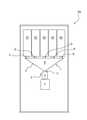
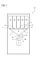
- FIG. 1is a schematic side view of a machine for making liquid and/or semiliquid products in which the transfer device of the invention is installed;
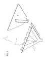
- FIGS. 2 and 3are perspective views of the transfer device in a disassembled condition
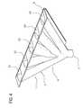
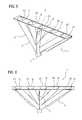
- FIGS. 4 to 6are perspective views of the transfer device in the assembled condition
- FIG. 7is a schematic side view of a further embodiment of a machine for making liquid and/or semiliquid products in which the transfer device of the invention is installed.
- the numeral 1denotes a device for transferring liquid, semiliquid or powdered basic products applicable to a machine 100 for making liquid and/or semiliquid products (preferably, but not necessarily, for making ice cream).
- the transfer device 1comprises a main body 2 configured to form a plurality of transfer channels C 1 , C 2 , C 3 , C 4 , C 5 defining respective conveying paths which are at least partly separate from one another.
- Each transfer channel (C 1 , C 2 , C 3 , C 4 , C 5 )has a respective inlet (I 1 , I 2 , I 3 , I 4 , I 5 ) which is separate from that of the other transfer channels (C 1 , C 2 , C 3 , C 4 , C 5 ).
- the main body 2has an outlet U shared by the transfer channels (C 1 , C 2 , C 3 , C 4 , C 5 ), in which the selfsame channels (C 1 , C 2 , C 3 , C 4 , C 5 ) converge.
- the main body 2has a plurality of inlets (I 1 , I 2 , I 3 , I 4 , I 5 ), one for each transfer channel (C 1 , C 2 , C 3 , C 4 , C 5 ).
- the main body 2comprises a rear wall A, in which seats are made which form the transfer channels (C 1 , C 2 , C 3 , C 4 , C 5 ), and a second, front wall B which can be coupled to the rear wall A for closing the seats (and thereby forming the transfer channels (C 1 , C 2 , C 3 , C 4 , C 5 ).
- the front wall Bis a flat wall (which, in use, is positioned vertically).
- one of the channels of the plurality of transfer channels(C 1 , C 2 , C 3 , C 4 , C 5 ) is positioned centrally and the other channels of the plurality of transfer channels (C 1 . C 2 , C 3 , C 4 , C 5 ) are positioned on either side of that one of the plurality of transfer channels (C 1 , C 2 , C 3 , C 4 , C 5 ) which is positioned centrally.
- a first portion of the other channels of the plurality of transfer channels(C 1 , C 2 , C 3 . C 4 , C 5 ) is positioned in a right-hand region, whilst a second portion of the other channels of the plurality of transfer channels (C 1 , C 2 , C 3 , C 4 , C 5 ) is positioned in a left-hand region, relative to that one of the plurality of transfer channels (C 1 , C 2 , C 3 , C 4 , C 5 ).
- the device 1preferably comprises a separating wall C which, in use, is associated with the main body 2 and positioned (inside the main body 2 ) in such a way that it affects the conveying path of at least some of the transfer channels (C 1 , C 2 , C 3 , C 4 , C 5 ).
- the separating wall Cis positioned in such a way that it affects the conveying path of all of the transfer channels (C 1 , C 2 , C 3 , C 4 , C 5 ).
- the separating wall Cis, in use, positioned substantially vertically.
- the separating wall Cis positioned inside the main body 2 .
- the separating wall Cis fixed to the front wall B in such a way as to be integral with the front wall B.
- each of the channelsis configured to define a main transfer direction which is inclined at an angle to a vertical direction.
- the transfer channels (C 1 , C 2 , C 3 , C 4 , C 5 )are oriented in such a way that they are angled, the angle of inclination increasing from the centre towards the periphery of the main body 2 .
- peripheral transfer channelsare inclined at a greater angle than the central transfer channels.
- main body 2has a tapered shape.
- the main body 2is tapered downwardly.
- FIG. 1Also defined according to the invention is a system for mixing liquid, semi-liquid or powdered basic products (illustrated in FIG. 1 ), comprising:
- the mixing chamber 4is provided with a basic products inlet which—in use—receives the basic products from the transfer device 1 .
- the mixing systemforms part of a machine 100 (schematically illustrated in FIG. 1 ) for making liquid and/or semiliquid products.
- the machine 100comprises the mixing system described previously and further comprises:
- the processing chamber 5is a mixing and freezing chamber where the mixture being processed comprising the basic products, the basic liquid and, if necessary, other ingredients, is stirred and simultaneously cooled in such a way as to increase the volume of the mixture by incorporating air into it (mixing and freezing).
- the basic products needed to make the required finished productare fed down from the respective tanks (S 1 , S 2 , S 3 , S 4 , S 5 ) where they are stored.
- each transfer channel (C 1 , C 2 , C 3 , C 4 , C 5 )is connected to one tank only in order to receive therefrom a predetermined basic product (liquid, semiliquid or powdered).
- each basic productoccupies one of the channels of the transfer device 1 and is gravity fed down the transfer path defined by the channel itself.
- the mixing of one or more basic productsoccurs only inside the mixing chamber 4 .
- the device 1advantageously prevents different basic products from being mixed outside the mixing chamber 4 .
- mixing outside the mixing chamber 4is absolutely to be avoided especially when two different “flavors” (that is, different types of finished product) requiring the use of two different basic products are made directly one after the other in effect, in such a case, it is important for one “flavor” not to contain any residues of the basic product of another flavor made beforehand.
- the separating wall Cadvantageously contributes to preventing the basic products, which are transferred through different transfer channels (C 1 , C 2 , C 3 , C 4 , C 5 ) from being mixed inside the main body 2 of the transfer device 1 .
- the fact that the separating wall C is verticalmeans that the basic products do not adhere to the wall C itself and, therefore, that no residues of the basic products remain inside the device 1 .
- the fact that the device 1comprises two walls, a rear wall A and a front wall B, which can be coupled to each other, makes the device 1 easy to disassemble for cleaning purpose.
- the transfer device 1 according to the inventionis particularly easy to clean.
- the mixing systemfurther comprises a selective connection device M operatively interposed between the outlet U of the transfer device 1 and the inlet of the mixing chamber 4 , the selective connection device being alternately switchable between two configurations (one configuration for making the connection and one configuration for breaking the connection), for alternately connecting or disconnecting the outlet U of the transfer device 1 and the inlet of the mixing chamber 4 .
- the outlet U of the transfer device 1 and the inlet of the mixing chamber 4are connected to each other to allow the basic products to pass freely from the transfer device 1 to the mixing chamber 4 , while in the configuration for breaking the connection, the outlet U of the transfer device 1 and the inlet of the mixing chamber 4 are not connected to each other (thus preventing the basic products from passing freely from the transfer device 1 to the mixing chamber 4 ).
- the purpose of the selective connection device Mis to (automatically) allow breaking the connection between the outlet U of the transfer device 1 and the inlet (of the basic products) of the mixing chamber 4 so as to prevent the steam (produced by the hot water) fed into the mixing chamber 4 (during use and, in particular, during sterilization) from rising up back into the channels (C 1 ,C 2 ,C 3 ,C 4 ,C 5 ) of the transfer device 1 , reaching the tanks and moistening the basic products.
- the selective connection device Mis preferably controlled by a drive and control unit forming part of the mixing system.
- the selective connection device Mallows the steam produced in the mixing chamber 4 to be extracted by suction (without flowing through the channels C 1 ,C 2 ,C 3 ,C 4 ,C 5 of the transfer device 1 ).
- the selective connection deviceis preferably in the configuration for breaking the connection so as to prevent the steam from rising up back towards the tanks of the basic products.
- the selective connection devicecomprises a valve M 1 (schematically illustrated in FIG. 7 ) operatively interposed between the outlet U of the transfer device 1 and the basic products inlet of the mixing chamber 4 .
- the valve M 1is switchable between a configuration for making the connection, where the outlet U of the transfer device 1 and the inlet of the mixing chamber 4 are connected to each other, and a configuration for breaking the connection, where the outlet U of the transfer device 1 and the inlet of the mixing chamber 4 are not connected to each other.
- the valve M 1may be of any type; more preferably, the valve is a ball valve or a slide valve.
- valve M 1is driven by an actuator M 2 (schematically illustrated in FIG. 7 ).
- the actuatoris an electric actuator.
- the electric actuatoris an electric motor.
Landscapes
- Chemical & Material Sciences (AREA)
- Engineering & Computer Science (AREA)
- Chemical Kinetics & Catalysis (AREA)
- Life Sciences & Earth Sciences (AREA)
- Food Science & Technology (AREA)
- Polymers & Plastics (AREA)
- Manufacturing & Machinery (AREA)
- Confectionery (AREA)
Abstract
Description
This application claims priority to Italian Patent Application No. BO2014A000270 filed May 7, 2014, which application is incorporated by reference herein.
This invention relates to a device for transferring liquid, semiliquid or powdered products and to a system for mixing the products.
Known in the ice cream machine industry are machines comprising a plurality of storage tanks containing basic products (liquid, semiliquid or powdered) and a hopper designed to receive the products from the tanks and to convey them towards a mixing chamber underneath.
A need felt by this industry is the need, when the basic product is changed, to prevent the new basic product from being mixed with the previously used basic product outside the mixing chamber.
This invention has for an aim to meet the above mentioned need.
One aim of this invention is to provide a device for transferring liquid, semiliquid or powdered basic products, applicable to machines for making liquid or semiliquid products, wherein mixing of the basic products being transferred is substantially prevented.
Another aim of the invention is to provide a device for transferring liquid, semiliquid or powdered basic products which does not necessitate cleaning and/or maintenance when the basic product/products being fed is/are changed
A further aim of the invention is to provide a device for transferring liquid, semiliquid or powdered basic products which is easy to disassemble for cleaning or inspection purposes.
These aims are achieved by a device for transferring liquid, semiliquid or powdered basic products and a mixing system, forming the object of the invention and comprising the technical features described herein.
The technical features, with reference to the above aims, are clearly described herein with advantages being apparent from the detailed description which follows, with reference to the accompanying drawings which illustrate a non-limiting example embodiment of the invention and in which:
With reference to the accompanying drawings, thenumeral 1 denotes a device for transferring liquid, semiliquid or powdered basic products applicable to amachine 100 for making liquid and/or semiliquid products (preferably, but not necessarily, for making ice cream).
According to the invention, thetransfer device 1 comprises amain body 2 configured to form a plurality of transfer channels C1, C2, C3, C4, C5 defining respective conveying paths which are at least partly separate from one another.
Each transfer channel (C1, C2, C3, C4, C5) has a respective inlet (I1, I2, I3, I4, I5) which is separate from that of the other transfer channels (C1, C2, C3, C4, C5).
Themain body 2 has an outlet U shared by the transfer channels (C1, C2, C3, C4, C5), in which the selfsame channels (C1, C2, C3, C4, C5) converge.
Further, as already stated, themain body 2 has a plurality of inlets (I1, I2, I3, I4, I5), one for each transfer channel (C1, C2, C3, C4, C5).
In the embodiment illustrated, themain body 2 comprises a rear wall A, in which seats are made which form the transfer channels (C1, C2, C3, C4, C5), and a second, front wall B which can be coupled to the rear wall A for closing the seats (and thereby forming the transfer channels (C1, C2, C3, C4, C5).
Preferably, the front wall B is a flat wall (which, in use, is positioned vertically).
With reference to the accompanying drawings, it should be noted that one of the channels of the plurality of transfer channels (C1, C2, C3, C4, C5) is positioned centrally and the other channels of the plurality of transfer channels (C1. C2, C3, C4, C5) are positioned on either side of that one of the plurality of transfer channels (C1, C2, C3, C4, C5) which is positioned centrally.
More specifically, it should be noted that a first portion of the other channels of the plurality of transfer channels (C1, C2, C3. C4, C5) is positioned in a right-hand region, whilst a second portion of the other channels of the plurality of transfer channels (C1, C2, C3, C4, C5) is positioned in a left-hand region, relative to that one of the plurality of transfer channels (C1, C2, C3, C4, C5).
According to another aspect, thedevice 1 preferably comprises a separating wall C which, in use, is associated with themain body 2 and positioned (inside the main body2) in such a way that it affects the conveying path of at least some of the transfer channels (C1, C2, C3, C4, C5).
More preferably, the separating wall C is positioned in such a way that it affects the conveying path of all of the transfer channels (C1, C2, C3, C4, C5).
It should be noted that in the embodiment illustrated, the separating wall C is, in use, positioned substantially vertically.
It should also be noted that the separating wall C is positioned inside themain body 2.
It should be noted that in the embodiment illustrated, the separating wall C is fixed to the front wall B in such a way as to be integral with the front wall B.
It should be noted that the transfer channels (C1, C2, C3, C4, C5) are oriented in such a way that they are angled relative to a vertical direction. In other words, each of the channels is configured to define a main transfer direction which is inclined at an angle to a vertical direction.
The transfer channels (C1, C2, C3, C4, C5) are oriented in such a way that they are angled, the angle of inclination increasing from the centre towards the periphery of themain body 2.
It should be noted therefore that the peripheral transfer channels are inclined at a greater angle than the central transfer channels.
It should also be noted that themain body 2 has a tapered shape.
More specifically, in use, themain body 2 is tapered downwardly.
Also defined according to the invention is a system for mixing liquid, semi-liquid or powdered basic products (illustrated inFIG. 1 ), comprising:
- a plurality of storage tanks (S1, S2, S3, S4, S5) for liquid, semi-liquid or powdered basic products;
- a
mixing chamber 4 for mixing said liquid, semi-liquid or powdered basic products, comprising adevice 6 for introducing a basic liquid (preferably water) into themixing chamber 4, and configured to allow mixing the basic liquid with the basic products; - the
transfer device 1 as described above, operatively interposed between the storage tanks (S1, S2, S3, S4, S5) and themixing chamber 4 for transferring the basic products from the tanks (S1, S2, S3, S4, S5) to themixing chamber 4.
It should be noted that themixing chamber 4 is provided with a basic products inlet which—in use—receives the basic products from thetransfer device 1.
The mixing system forms part of a machine100 (schematically illustrated inFIG. 1 ) for making liquid and/or semiliquid products.
Themachine 100 comprises the mixing system described previously and further comprises:
- a
processing chamber 5, equipped with a mixer and with thermal treatment means, operatively coupled with the mixing chamber (4) for receiving the basic products mixed with the basic liquid and for converting them into a liquid or semiliquid finished product.
- a
It should be noted that theprocessing chamber 5 is a mixing and freezing chamber where the mixture being processed comprising the basic products, the basic liquid and, if necessary, other ingredients, is stirred and simultaneously cooled in such a way as to increase the volume of the mixture by incorporating air into it (mixing and freezing).
Below is a brief description of how thetransfer device 1 operates and from which further advantageous technical features may be inferred.
It should be noted that to make a finished product (or “flavor”) in themachine 100, one or more basic products must be used.
The basic products needed to make the required finished product are fed down from the respective tanks (S1, S2, S3, S4, S5) where they are stored.
More specifically, it should be noted that the inlet (I1, I2, I3, I4, I5) of each transfer channel (C1, C2, C3, C4, C5) is connected to one tank only in order to receive therefrom a predetermined basic product (liquid, semiliquid or powdered).
After being released by the respective tank, each basic product occupies one of the channels of thetransfer device 1 and is gravity fed down the transfer path defined by the channel itself.
Thanks to the special structure of thetransfer device 1, the mixing of one or more basic products occurs only inside themixing chamber 4.
It should be noted, therefore, that thedevice 1 advantageously prevents different basic products from being mixed outside themixing chamber 4.
Indeed, mixing outside themixing chamber 4 is absolutely to be avoided especially when two different “flavors” (that is, different types of finished product) requiring the use of two different basic products are made directly one after the other in effect, in such a case, it is important for one “flavor” not to contain any residues of the basic product of another flavor made beforehand.
It should be noted that the separating wall C advantageously contributes to preventing the basic products, which are transferred through different transfer channels (C1, C2, C3, C4, C5) from being mixed inside themain body 2 of thetransfer device 1.
Moreover, the fact that the separating wall C is vertical means that the basic products do not adhere to the wall C itself and, therefore, that no residues of the basic products remain inside thedevice 1.
Also, advantageously, the fact that thedevice 1 comprises two walls, a rear wall A and a front wall B, which can be coupled to each other, makes thedevice 1 easy to disassemble for cleaning purpose.
In effect, in order to clean the transfer channels (C1, C2, C3, C4, C5), it is sufficient to remove the rear wall B to access the seats which define the channels.
It should be noted that thetransfer device 1 according to the invention is particularly easy to clean.
According to another aspect, illustrated in the embodiment shown inFIG. 7 , the mixing system further comprises a selective connection device M operatively interposed between the outlet U of thetransfer device 1 and the inlet of themixing chamber 4, the selective connection device being alternately switchable between two configurations (one configuration for making the connection and one configuration for breaking the connection), for alternately connecting or disconnecting the outlet U of thetransfer device 1 and the inlet of themixing chamber 4.
It should be noted that in the configuration for making the connection, the outlet U of thetransfer device 1 and the inlet of themixing chamber 4 are connected to each other to allow the basic products to pass freely from thetransfer device 1 to themixing chamber 4, while in the configuration for breaking the connection, the outlet U of thetransfer device 1 and the inlet of themixing chamber 4 are not connected to each other (thus preventing the basic products from passing freely from thetransfer device 1 to the mixing chamber4).
The purpose of the selective connection device M is to (automatically) allow breaking the connection between the outlet U of thetransfer device 1 and the inlet (of the basic products) of the mixingchamber 4 so as to prevent the steam (produced by the hot water) fed into the mixing chamber4 (during use and, in particular, during sterilization) from rising up back into the channels (C1,C2,C3,C4,C5) of thetransfer device 1, reaching the tanks and moistening the basic products.
It should be noted that the selective connection device M is preferably controlled by a drive and control unit forming part of the mixing system.
It should be noted that the selective connection device M allows the steam produced in the mixingchamber 4 to be extracted by suction (without flowing through the channels C1,C2,C3,C4,C5 of the transfer device1).
In use, therefore, when product is not required to be fed down through the channels C1,C2,C3,C4,C5 of thetransfer device 1, the selective connection device is preferably in the configuration for breaking the connection so as to prevent the steam from rising up back towards the tanks of the basic products.
In a preferred embodiment, the selective connection device comprises a valve M1 (schematically illustrated inFIG. 7 ) operatively interposed between the outlet U of thetransfer device 1 and the basic products inlet of the mixingchamber 4.
The valve M1 is switchable between a configuration for making the connection, where the outlet U of thetransfer device 1 and the inlet of the mixingchamber 4 are connected to each other, and a configuration for breaking the connection, where the outlet U of thetransfer device 1 and the inlet of the mixingchamber 4 are not connected to each other.
Preferably, the valve M1 may be of any type; more preferably, the valve is a ball valve or a slide valve.
Preferably, the valve M1 is driven by an actuator M2 (schematically illustrated inFIG. 7 ).
Preferably, the actuator is an electric actuator.
Still more preferably, the electric actuator is an electric motor.
Claims (13)
1. A transfer device for transferring liquid, semiliquid or powdered basic products, comprising:
a main body including a plurality of transfer channels defining respective conveying paths which are at least partly separate from one another, the main body including a plurality of inlets, one for each of the plurality of transfer channels, the main body comprising an outlet shared by the plurality of transfer channels, in which the plurality of transfer channels converge;
wherein the main body comprises a rear wall, in which seats are made which form the plurality of transfer channels, and a separate front wall reversibly couplable with the rear wall for closing the seats.
2. The transfer device according toclaim 1 , wherein the front wall is a flat wall.
3. The transfer device according toclaim 1 , wherein one of the plurality of transfer channels is positioned centrally and the other of the plurality of transfer channels are positioned on either side of the one of the plurality of transfer channels which is positioned centrally.
4. The transfer device according toclaim 3 , wherein a first portion of the other of the plurality of transfer channels is positioned in a right-hand region, whilst a second portion of the other of the plurality of transfer channels is positioned in a left-hand region, relative to said one of the plurality of transfer channels.
5. The transfer device according toclaim 1 , and further comprising a separating wall positioned in the main body and extending between the rear wall and the front wall to affect a conveying path of at least some of the plurality of transfer channels.
6. The transfer device according toclaim 5 , wherein the separating wall is, in use, positioned substantially vertically.
7. The transfer device according toclaim 1 , and further comprising a separating wall positioned in the main body and extending between the rear wall and the front we to affect a conveying path of all of the plurality of transfer channels.
8. The transfer device according toclaim 1 , wherein the main body comprises:
a separating wall positioned in the main body and extending between the rear wall and the front wall to affect a conveying path of at least some of the plurality of transfer channels,
wherein the separating wall is secured to the front wall.
9. The transfer device according toclaim 1 , wherein the plurality of transfer channels are oriented to be angled relative to a vertical direction.
10. The transfer device according toclaim 9 , wherein the plurality of transfer channels are oriented to be angled, with an angle of inclination of the plurality of transfer channels increasing towards a periphery of the main body.
11. A system for mixing liquid, semiliquid or powdered basic products, comprising:
a plurality of storage tanks for liquid, semiliquid or powdered basic products;
a mixing chamber for mixing the liquid, semiliquid or powdered basic products, comprising a device for introducing a basic liquid into the mixing chamber and allowing mixing of the basic liquid with the liquid, semiliquid or powdered basic products;
a transfer device according toclaim 1 , operatively interposed between the plurality of storage tanks and the mixing chamber for transferring the liquid, semiliquid or powdered basic products from the storage tanks to the mixing chamber.
12. The system according toclaim 11 , and further comprising a selective connection device operatively interposed between an outlet of the transfer device and a basic products inlet of the mixing chamber, the selective connection device being alternately switchable between two configurations, for alternately connecting or disconnecting the outlet of the transfer device and the basic products inlet of the mixing chamber.
13. A machine for making liquid or semiliquid products, comprising the mixing system ofclaim 12 , and further comprising:
a processing chamber, including a mixer and a thermal treatment system, operatively coupled with the mixing chamber for receiving the liquid, semiliquid or powdered basic products mixed with the basic liquid and for converting them into a liquid or semiliquid finished product.
Applications Claiming Priority (3)
| Application Number | Priority Date | Filing Date | Title |
|---|---|---|---|
| ITBO2014A0270 | 2014-05-07 | ||
| ITBO20140270 | 2014-05-07 | ||
| ITBO2014A000270 | 2014-05-07 |
Publications (2)
| Publication Number | Publication Date |
|---|---|
| US20150320078A1 US20150320078A1 (en) | 2015-11-12 |
| US9737083B2true US9737083B2 (en) | 2017-08-22 |
Family
ID=51178986
Family Applications (1)
| Application Number | Title | Priority Date | Filing Date |
|---|---|---|---|
| US14/706,112ActiveUS9737083B2 (en) | 2014-05-07 | 2015-05-07 | Device for transferring liquid, semiliquid or powdered products and system for mixing the products |
Country Status (1)
| Country | Link |
|---|---|
| US (1) | US9737083B2 (en) |
Families Citing this family (7)
| Publication number | Priority date | Publication date | Assignee | Title |
|---|---|---|---|---|
| ITUB20154199A1 (en) | 2015-10-07 | 2017-04-07 | Carpigiani Group Ali Spa | MACHINE AND METHOD FOR THE REALIZATION OF LIQUID AND SEMILIQUID PRODUCTS OF THE HOT OR COLD TYPE. |
| WO2017118524A1 (en) | 2016-01-08 | 2017-07-13 | Unilever Plc | Apparatus for delivering frozen confection comprising particulate material |
| CN108471774A (en) | 2016-01-08 | 2018-08-31 | 荷兰联合利华有限公司 | Equipment for conveying frozen confectionery including granular material |
| IT201600074471A1 (en)* | 2016-07-15 | 2018-01-15 | Ali Group Srl Carpigiani | MACHINE AND METHOD FOR THE PRODUCTION OF LIQUID AND SEMIQUID PRODUCTS OF THE ICE CREAM, PASTRY OR RESTAURANT SECTOR. |
| IT201600100869A1 (en) | 2016-10-07 | 2018-04-07 | Ali Group Srl Carpigiani | METHOD AND CLEANING SYSTEM OF A MACHINE FOR THE REALIZATION OF LIQUID AND / OR SEMIQUINE FOODSTUFFS IN THE ICE-CREAM, PASTRY OR RESTAURANT SECTOR |
| US11076613B2 (en)* | 2016-10-24 | 2021-08-03 | The Vollrath Company, L.L.C. | Frozen food product dispensing machine including mixing manifold |
| IT201700043975A1 (en) | 2017-04-21 | 2018-10-21 | Ali Group Srl Carpigiani | MACHINE AND METHOD FOR THE PRODUCTION OF LIQUID AND SEMIQUID PRODUCTS OF THE ICE CREAM SECTOR. |
Citations (13)
| Publication number | Priority date | Publication date | Assignee | Title |
|---|---|---|---|---|
| US4363223A (en) | 1980-08-26 | 1982-12-14 | Inventco Sales Limited | Apparatus for producing and dispensing cold products |
| US4691850A (en)* | 1984-08-09 | 1987-09-08 | Kirschmann John D | Chemical dispensing system |
| US4747272A (en)* | 1985-10-04 | 1988-05-31 | Cherry-Burrell Corporation | Frozen comestibles with improved over-run control |
| US5292030A (en) | 1990-08-06 | 1994-03-08 | Kateman Family Limited Partnership | Method and apparatus for producing and dispensing aerated products |
| WO1998029328A1 (en) | 1996-12-26 | 1998-07-09 | Frank Jimmy I | A method and apparatus for monitoring and controlling the amount of liquid in a mixing chamber |
| US20030012864A1 (en) | 2001-01-25 | 2003-01-16 | Gerber Ernest C. | Product blender and dispenser |
| US6698228B2 (en)* | 2001-11-02 | 2004-03-02 | Moobella, Llc | Method and apparatus for producing and dispensing an aerated and/or blended food product |
| US20060134275A1 (en)* | 2002-07-19 | 2006-06-22 | Sanyo Electric Co., Ltd., | Liquid containing bag and frozen dessert manufacturing apparatus using the same |
| WO2006076733A2 (en) | 2005-01-14 | 2006-07-20 | Moobella Llc | Systems and methods for dispensing product |
| EP2095720A2 (en) | 2008-02-29 | 2009-09-02 | Carpigiani Group - Ali S.p.A. | Machine for producing and dispensing ice cream shop products. |
| EP2625964A2 (en) | 2012-02-09 | 2013-08-14 | Francesco Bravo | Machine with an improved cooling system for the production of ice-cream in doses |
| US8800610B2 (en)* | 2009-07-10 | 2014-08-12 | Krones Ag | Filling device for filling containers |
| US9186636B2 (en)* | 2012-04-19 | 2015-11-17 | Lingyu Dong | Frosty swirl machine |
- 2015
- 2015-05-07USUS14/706,112patent/US9737083B2/enactiveActive
Patent Citations (20)
| Publication number | Priority date | Publication date | Assignee | Title |
|---|---|---|---|---|
| US4363223A (en) | 1980-08-26 | 1982-12-14 | Inventco Sales Limited | Apparatus for producing and dispensing cold products |
| US4691850A (en)* | 1984-08-09 | 1987-09-08 | Kirschmann John D | Chemical dispensing system |
| US4747272A (en)* | 1985-10-04 | 1988-05-31 | Cherry-Burrell Corporation | Frozen comestibles with improved over-run control |
| US5292030A (en) | 1990-08-06 | 1994-03-08 | Kateman Family Limited Partnership | Method and apparatus for producing and dispensing aerated products |
| US5433967A (en)* | 1990-08-06 | 1995-07-18 | Kateman Family Limited Partnership | Method for producing and dispensing aerated or blended food products |
| US5603257A (en)* | 1990-08-06 | 1997-02-18 | Turbo Dynamix Limited Partnership | Apparatus for producing and dispensing aerated or blended fluid products |
| US5806550A (en)* | 1995-09-29 | 1998-09-15 | Frank Jimmy I | Method and apparatus for monitoring and controlling the amount of liquid in a mixing chamber |
| WO1998029328A1 (en) | 1996-12-26 | 1998-07-09 | Frank Jimmy I | A method and apparatus for monitoring and controlling the amount of liquid in a mixing chamber |
| US20050175767A1 (en)* | 2001-01-25 | 2005-08-11 | Gerber Ernest C. | Product blender and dispenser |
| US20030012864A1 (en) | 2001-01-25 | 2003-01-16 | Gerber Ernest C. | Product blender and dispenser |
| US6698228B2 (en)* | 2001-11-02 | 2004-03-02 | Moobella, Llc | Method and apparatus for producing and dispensing an aerated and/or blended food product |
| US20060134275A1 (en)* | 2002-07-19 | 2006-06-22 | Sanyo Electric Co., Ltd., | Liquid containing bag and frozen dessert manufacturing apparatus using the same |
| US8479531B2 (en)* | 2002-07-19 | 2013-07-09 | Sanyo Electric Co., Ltd. | Liquid containing bag and frozen dessert manufacturing apparatus using the same |
| WO2006076733A2 (en) | 2005-01-14 | 2006-07-20 | Moobella Llc | Systems and methods for dispensing product |
| US20070251260A1 (en)* | 2005-01-14 | 2007-11-01 | Baxter James R | Systems and methods for dispensing product |
| EP2095720A2 (en) | 2008-02-29 | 2009-09-02 | Carpigiani Group - Ali S.p.A. | Machine for producing and dispensing ice cream shop products. |
| US20090217825A1 (en)* | 2008-02-29 | 2009-09-03 | Gino Cocchi | Machine for producing and dispensing ice cream shop products |
| US8800610B2 (en)* | 2009-07-10 | 2014-08-12 | Krones Ag | Filling device for filling containers |
| EP2625964A2 (en) | 2012-02-09 | 2013-08-14 | Francesco Bravo | Machine with an improved cooling system for the production of ice-cream in doses |
| US9186636B2 (en)* | 2012-04-19 | 2015-11-17 | Lingyu Dong | Frosty swirl machine |
Non-Patent Citations (1)
| Title |
|---|
| Italian Search Report dated Jan. 22, 2015 from counterpart App No. BO20140270. |
Also Published As
| Publication number | Publication date |
|---|---|
| US20150320078A1 (en) | 2015-11-12 |
Similar Documents
| Publication | Publication Date | Title |
|---|---|---|
| US9737083B2 (en) | Device for transferring liquid, semiliquid or powdered products and system for mixing the products | |
| US10905134B2 (en) | Base/additive product feeding unit for a machine for the production and/or distribution of an ice cream product and machine comprising said unit | |
| CN107788200B (en) | Machines for making liquid or semi-liquid products | |
| EP2866579B1 (en) | Frozen food dispensing machine and method of operation | |
| CN103249666B (en) | Be applicable to the method and apparatus distributing beverage from liquid concentrate | |
| US10478011B2 (en) | Method for preparing a fresh brewed cold coffee beverage and coffee machine for conducting such method | |
| US10556258B2 (en) | Method for cleaning a machine for liquid or semi-liquid food products | |
| US20140322415A1 (en) | Device for producing milk foam | |
| US10653164B2 (en) | Ice cream dispensing device and method and machine for making ice cream | |
| CN102046051A (en) | Mixing and dispensing apparatus with movable mixing chamber | |
| GB2526664A (en) | Device for producing soft ice-cream | |
| CN103771315B (en) | For the device at least one container filling fill thing | |
| CN110313832A (en) | The beverage dispenser converted is rushed suitable for magma | |
| CN106616413B (en) | Chicken feet material mixer | |
| US12285712B2 (en) | Dust collection device and method for filtering powder | |
| CN216748877U (en) | Feeding mechanism and meal making and selling machine | |
| CN212437181U (en) | Small-size cooking pot for grain cooking | |
| CN102334915B (en) | Device for tempering | |
| CN208194230U (en) | A kind of united stainless steel material-compound tank of multiple-tank body | |
| CN115444278A (en) | Liquid heat exchange device for making iced drinks and method for making iced coffee | |
| US473885A (en) | merrell | |
| ITBO20110133A1 (en) | EQUIPMENT FOR THE PREPARATION OF GAS COOLED DRINKS |
Legal Events
| Date | Code | Title | Description |
|---|---|---|---|
| AS | Assignment | Owner name:ALI S.P.A. - CARPIGIANI GROUP, ITALY Free format text:ASSIGNMENT OF ASSIGNORS INTEREST;ASSIGNOR:COCCHI, ANDREA;REEL/FRAME:035583/0970 Effective date:20150507 | |
| STCF | Information on status: patent grant | Free format text:PATENTED CASE | |
| AS | Assignment | Owner name:ALI GROUP S.R.L. - CARPIGIANI, ITALY Free format text:ASSIGNMENT OF ASSIGNORS INTEREST;ASSIGNOR:ALI S.P.A. - CARPIGIANI GROUP;REEL/FRAME:048288/0459 Effective date:20180219 | |
| MAFP | Maintenance fee payment | Free format text:PAYMENT OF MAINTENANCE FEE, 4TH YEAR, LARGE ENTITY (ORIGINAL EVENT CODE: M1551); ENTITY STATUS OF PATENT OWNER: LARGE ENTITY Year of fee payment:4 | |
| MAFP | Maintenance fee payment | Free format text:PAYMENT OF MAINTENANCE FEE, 8TH YEAR, LARGE ENTITY (ORIGINAL EVENT CODE: M1552); ENTITY STATUS OF PATENT OWNER: LARGE ENTITY Year of fee payment:8 |