US9736789B2 - Power line communication-based local hotspot with wireless power control capability - Google Patents
Power line communication-based local hotspot with wireless power control capabilityDownload PDFInfo
- Publication number
- US9736789B2 US9736789B2US13/725,144US201213725144AUS9736789B2US 9736789 B2US9736789 B2US 9736789B2US 201213725144 AUS201213725144 AUS 201213725144AUS 9736789 B2US9736789 B2US 9736789B2
- Authority
- US
- United States
- Prior art keywords
- radio frequency
- power level
- wireless hotspot
- wireless
- frequency output
- Prior art date
- Legal status (The legal status is an assumption and is not a legal conclusion. Google has not performed a legal analysis and makes no representation as to the accuracy of the status listed.)
- Expired - Fee Related
Links
Images


Classifications
- H—ELECTRICITY
- H02—GENERATION; CONVERSION OR DISTRIBUTION OF ELECTRIC POWER
- H02J—CIRCUIT ARRANGEMENTS OR SYSTEMS FOR SUPPLYING OR DISTRIBUTING ELECTRIC POWER; SYSTEMS FOR STORING ELECTRIC ENERGY
- H02J13/00—Circuit arrangements for providing remote indication of network conditions, e.g. an instantaneous record of the open or closed condition of each circuitbreaker in the network; Circuit arrangements for providing remote control of switching means in a power distribution network, e.g. switching in and out of current consumers by using a pulse code signal carried by the network
- H02J13/00006—Circuit arrangements for providing remote indication of network conditions, e.g. an instantaneous record of the open or closed condition of each circuitbreaker in the network; Circuit arrangements for providing remote control of switching means in a power distribution network, e.g. switching in and out of current consumers by using a pulse code signal carried by the network characterised by information or instructions transport means between the monitoring, controlling or managing units and monitored, controlled or operated power network element or electrical equipment
- H02J13/00028—Circuit arrangements for providing remote indication of network conditions, e.g. an instantaneous record of the open or closed condition of each circuitbreaker in the network; Circuit arrangements for providing remote control of switching means in a power distribution network, e.g. switching in and out of current consumers by using a pulse code signal carried by the network characterised by information or instructions transport means between the monitoring, controlling or managing units and monitored, controlled or operated power network element or electrical equipment involving the use of Internet protocols
- H—ELECTRICITY
- H04—ELECTRIC COMMUNICATION TECHNIQUE
- H04W—WIRELESS COMMUNICATION NETWORKS
- H04W52/00—Power management, e.g. Transmission Power Control [TPC] or power classes
- H04W52/04—Transmission power control [TPC]
- H04W52/18—TPC being performed according to specific parameters
- H04W52/24—TPC being performed according to specific parameters using SIR [Signal to Interference Ratio] or other wireless path parameters
- H04W52/245—TPC being performed according to specific parameters using SIR [Signal to Interference Ratio] or other wireless path parameters taking into account received signal strength
- H—ELECTRICITY
- H02—GENERATION; CONVERSION OR DISTRIBUTION OF ELECTRIC POWER
- H02J—CIRCUIT ARRANGEMENTS OR SYSTEMS FOR SUPPLYING OR DISTRIBUTING ELECTRIC POWER; SYSTEMS FOR STORING ELECTRIC ENERGY
- H02J13/00—Circuit arrangements for providing remote indication of network conditions, e.g. an instantaneous record of the open or closed condition of each circuitbreaker in the network; Circuit arrangements for providing remote control of switching means in a power distribution network, e.g. switching in and out of current consumers by using a pulse code signal carried by the network
- H02J13/00002—Circuit arrangements for providing remote indication of network conditions, e.g. an instantaneous record of the open or closed condition of each circuitbreaker in the network; Circuit arrangements for providing remote control of switching means in a power distribution network, e.g. switching in and out of current consumers by using a pulse code signal carried by the network characterised by monitoring
- H—ELECTRICITY
- H02—GENERATION; CONVERSION OR DISTRIBUTION OF ELECTRIC POWER
- H02J—CIRCUIT ARRANGEMENTS OR SYSTEMS FOR SUPPLYING OR DISTRIBUTING ELECTRIC POWER; SYSTEMS FOR STORING ELECTRIC ENERGY
- H02J13/00—Circuit arrangements for providing remote indication of network conditions, e.g. an instantaneous record of the open or closed condition of each circuitbreaker in the network; Circuit arrangements for providing remote control of switching means in a power distribution network, e.g. switching in and out of current consumers by using a pulse code signal carried by the network
- H02J13/00006—Circuit arrangements for providing remote indication of network conditions, e.g. an instantaneous record of the open or closed condition of each circuitbreaker in the network; Circuit arrangements for providing remote control of switching means in a power distribution network, e.g. switching in and out of current consumers by using a pulse code signal carried by the network characterised by information or instructions transport means between the monitoring, controlling or managing units and monitored, controlled or operated power network element or electrical equipment
- H02J13/00007—Circuit arrangements for providing remote indication of network conditions, e.g. an instantaneous record of the open or closed condition of each circuitbreaker in the network; Circuit arrangements for providing remote control of switching means in a power distribution network, e.g. switching in and out of current consumers by using a pulse code signal carried by the network characterised by information or instructions transport means between the monitoring, controlling or managing units and monitored, controlled or operated power network element or electrical equipment using the power network as support for the transmission
- H02J13/00009—Circuit arrangements for providing remote indication of network conditions, e.g. an instantaneous record of the open or closed condition of each circuitbreaker in the network; Circuit arrangements for providing remote control of switching means in a power distribution network, e.g. switching in and out of current consumers by using a pulse code signal carried by the network characterised by information or instructions transport means between the monitoring, controlling or managing units and monitored, controlled or operated power network element or electrical equipment using the power network as support for the transmission using pulsed signals
- H—ELECTRICITY
- H02—GENERATION; CONVERSION OR DISTRIBUTION OF ELECTRIC POWER
- H02J—CIRCUIT ARRANGEMENTS OR SYSTEMS FOR SUPPLYING OR DISTRIBUTING ELECTRIC POWER; SYSTEMS FOR STORING ELECTRIC ENERGY
- H02J13/00—Circuit arrangements for providing remote indication of network conditions, e.g. an instantaneous record of the open or closed condition of each circuitbreaker in the network; Circuit arrangements for providing remote control of switching means in a power distribution network, e.g. switching in and out of current consumers by using a pulse code signal carried by the network
- H02J13/00006—Circuit arrangements for providing remote indication of network conditions, e.g. an instantaneous record of the open or closed condition of each circuitbreaker in the network; Circuit arrangements for providing remote control of switching means in a power distribution network, e.g. switching in and out of current consumers by using a pulse code signal carried by the network characterised by information or instructions transport means between the monitoring, controlling or managing units and monitored, controlled or operated power network element or electrical equipment
- H02J13/00012—Circuit arrangements for providing remote indication of network conditions, e.g. an instantaneous record of the open or closed condition of each circuitbreaker in the network; Circuit arrangements for providing remote control of switching means in a power distribution network, e.g. switching in and out of current consumers by using a pulse code signal carried by the network characterised by information or instructions transport means between the monitoring, controlling or managing units and monitored, controlled or operated power network element or electrical equipment using an auxiliary transmission line
- H02J13/0024—
- H02J13/0055—
- H02J13/0082—
- G—PHYSICS
- G01—MEASURING; TESTING
- G01D—MEASURING NOT SPECIALLY ADAPTED FOR A SPECIFIC VARIABLE; ARRANGEMENTS FOR MEASURING TWO OR MORE VARIABLES NOT COVERED IN A SINGLE OTHER SUBCLASS; TARIFF METERING APPARATUS; MEASURING OR TESTING NOT OTHERWISE PROVIDED FOR
- G01D2204/00—Indexing scheme relating to details of tariff-metering apparatus
- G01D2204/10—Analysing; Displaying
- G01D2204/12—Determination or prediction of behaviour, e.g. likely power consumption or unusual usage patterns
- Y—GENERAL TAGGING OF NEW TECHNOLOGICAL DEVELOPMENTS; GENERAL TAGGING OF CROSS-SECTIONAL TECHNOLOGIES SPANNING OVER SEVERAL SECTIONS OF THE IPC; TECHNICAL SUBJECTS COVERED BY FORMER USPC CROSS-REFERENCE ART COLLECTIONS [XRACs] AND DIGESTS
- Y02—TECHNOLOGIES OR APPLICATIONS FOR MITIGATION OR ADAPTATION AGAINST CLIMATE CHANGE
- Y02B—CLIMATE CHANGE MITIGATION TECHNOLOGIES RELATED TO BUILDINGS, e.g. HOUSING, HOUSE APPLIANCES OR RELATED END-USER APPLICATIONS
- Y02B90/00—Enabling technologies or technologies with a potential or indirect contribution to GHG emissions mitigation
- Y02B90/20—Smart grids as enabling technology in buildings sector
- Y02B90/244—
- Y—GENERAL TAGGING OF NEW TECHNOLOGICAL DEVELOPMENTS; GENERAL TAGGING OF CROSS-SECTIONAL TECHNOLOGIES SPANNING OVER SEVERAL SECTIONS OF THE IPC; TECHNICAL SUBJECTS COVERED BY FORMER USPC CROSS-REFERENCE ART COLLECTIONS [XRACs] AND DIGESTS
- Y02—TECHNOLOGIES OR APPLICATIONS FOR MITIGATION OR ADAPTATION AGAINST CLIMATE CHANGE
- Y02E—REDUCTION OF GREENHOUSE GAS [GHG] EMISSIONS, RELATED TO ENERGY GENERATION, TRANSMISSION OR DISTRIBUTION
- Y02E60/00—Enabling technologies; Technologies with a potential or indirect contribution to GHG emissions mitigation
- Y02E60/74—
- Y02E60/7815—
- Y02E60/7823—
- Y—GENERAL TAGGING OF NEW TECHNOLOGICAL DEVELOPMENTS; GENERAL TAGGING OF CROSS-SECTIONAL TECHNOLOGIES SPANNING OVER SEVERAL SECTIONS OF THE IPC; TECHNICAL SUBJECTS COVERED BY FORMER USPC CROSS-REFERENCE ART COLLECTIONS [XRACs] AND DIGESTS
- Y04—INFORMATION OR COMMUNICATION TECHNOLOGIES HAVING AN IMPACT ON OTHER TECHNOLOGY AREAS
- Y04S—SYSTEMS INTEGRATING TECHNOLOGIES RELATED TO POWER NETWORK OPERATION, COMMUNICATION OR INFORMATION TECHNOLOGIES FOR IMPROVING THE ELECTRICAL POWER GENERATION, TRANSMISSION, DISTRIBUTION, MANAGEMENT OR USAGE, i.e. SMART GRIDS
- Y04S10/00—Systems supporting electrical power generation, transmission or distribution
- Y04S10/30—State monitoring, e.g. fault, temperature monitoring, insulator monitoring, corona discharge
- Y—GENERAL TAGGING OF NEW TECHNOLOGICAL DEVELOPMENTS; GENERAL TAGGING OF CROSS-SECTIONAL TECHNOLOGIES SPANNING OVER SEVERAL SECTIONS OF THE IPC; TECHNICAL SUBJECTS COVERED BY FORMER USPC CROSS-REFERENCE ART COLLECTIONS [XRACs] AND DIGESTS
- Y04—INFORMATION OR COMMUNICATION TECHNOLOGIES HAVING AN IMPACT ON OTHER TECHNOLOGY AREAS
- Y04S—SYSTEMS INTEGRATING TECHNOLOGIES RELATED TO POWER NETWORK OPERATION, COMMUNICATION OR INFORMATION TECHNOLOGIES FOR IMPROVING THE ELECTRICAL POWER GENERATION, TRANSMISSION, DISTRIBUTION, MANAGEMENT OR USAGE, i.e. SMART GRIDS
- Y04S20/00—Management or operation of end-user stationary applications or the last stages of power distribution; Controlling, monitoring or operating thereof
- Y04S20/30—Smart metering, e.g. specially adapted for remote reading
- Y04S20/327—
- Y—GENERAL TAGGING OF NEW TECHNOLOGICAL DEVELOPMENTS; GENERAL TAGGING OF CROSS-SECTIONAL TECHNOLOGIES SPANNING OVER SEVERAL SECTIONS OF THE IPC; TECHNICAL SUBJECTS COVERED BY FORMER USPC CROSS-REFERENCE ART COLLECTIONS [XRACs] AND DIGESTS
- Y04—INFORMATION OR COMMUNICATION TECHNOLOGIES HAVING AN IMPACT ON OTHER TECHNOLOGY AREAS
- Y04S—SYSTEMS INTEGRATING TECHNOLOGIES RELATED TO POWER NETWORK OPERATION, COMMUNICATION OR INFORMATION TECHNOLOGIES FOR IMPROVING THE ELECTRICAL POWER GENERATION, TRANSMISSION, DISTRIBUTION, MANAGEMENT OR USAGE, i.e. SMART GRIDS
- Y04S40/00—Systems for electrical power generation, transmission, distribution or end-user application management characterised by the use of communication or information technologies, or communication or information technology specific aspects supporting them
- Y04S40/12—Systems for electrical power generation, transmission, distribution or end-user application management characterised by the use of communication or information technologies, or communication or information technology specific aspects supporting them characterised by data transport means between the monitoring, controlling or managing units and monitored, controlled or operated electrical equipment
- Y04S40/121—Systems for electrical power generation, transmission, distribution or end-user application management characterised by the use of communication or information technologies, or communication or information technology specific aspects supporting them characterised by data transport means between the monitoring, controlling or managing units and monitored, controlled or operated electrical equipment using the power network as support for the transmission
- Y04S40/122—
Definitions
- the inventionrelates to providing wireless coverage within a local area network. More specifically the invention is directed to providing multiple hotspots providing effective area coverage within a wireless local area network with the hotspots spatially separated, but operating simultaneously.
- PLCpower line communication
- One such application that is emergingis providing effective wireless coverage within a local area (wireless LAN area) such as an office, home, small business location, etc. using multiple wireless hotspot sensor (WHS) devices simultaneously.
- a local areawireless LAN area
- WSSwireless hotspot sensor
- One problem of having multiple WHS devices or units operating using the same frequency in proximity to each otheris interference and fading within the coverage area due to signal overlap from the transmitted signals from multiple WHS devices.
- Multiple WHS devicesbecome necessary when the wireless LAN area that needs to be covered by wireless connectivity exceeds the capability of a single WHS device.
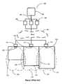
- FIG. 1is a pictorial depiction 100 of prior art.
- the data from a data store 101is modulated in the modulators 102 , 103 , and 104 , each using a different frequency.
- the modulated frequencyis impressed over the same transmission medium and sent through the cloud 105 .
- the transmitted modulated datais received and separated into the three frequencies using the filters 120 , 121 , and 122 .
- the datais transmitted by the adjacent WHS devices 123 , 124 , and 125 , each using a different frequency.
- adjacent WHS devicesoperate at different frequencies covering the three adjacent rooms 110 , 111 , and 112 .
- the adjacent sensor devices 123 , 124 , and 125are designed to have differing frequencies that do not interfere with each other even though the sensors are close to each other.
- With the transmitted power lobes 126 , 127 , and 128 overlapping at regions 130 and 131if a single frequency spectrum is used for transmission of data by the sensors, then fading and interference in will occur in the regions of overlap 130 and 131 , limiting the coverage provided.
- sensors with multiple frequenciesis an elegant solution to the interference and fading problem when covering a LAN covering a large area
- the use of multiple frequenciesrequires transmitters, filters, and sensors for each distinct frequency used by sensors that are adjacent to each other. This is an expensive solution.
- thisis the only solution available today where multiple hotspots are needed to cover large areas within a wireless LAN because it is not feasible to cover the area with a single WHS unit.
- a WHS systemcomprises multiple WHSs in a local area network (LAN) in which each of the multiple sensors transmits using the same frequency spectrum.
- Each of the WHSscomprises a switch and a power level indicator.
- the switch on each sensormay be used to adjust the radio frequency (RF) power levels transmitted by the sensor.
- the power level indicator on each sensorprovides an indication of how much power is being used to transmit the wireless signal.
- the power lobe for one sensormay interfere with the power lobe of another adjacent sensor, causing interference and fading.
- a methodis provided for adjusting the power of each sensor independently so as to optimize coverage of the local area and to minimize interference and fading.
- Coverage provided by the power lobe generated by each sensoris measured or checked at usable locations within the expected coverage area using a standard wireless transmitter-receiver unit, and the power is increased to maximize coverage. However, if the power level setting that provides coverage causes interference or fading at the receiver at usable locations, then the power is decreased to minimize the interference or fading. Determining coverage, interference, and fading determines whether to increase, decrease, or maintain the power level for each sensor, thereby providing the best usable wireless coverage within the LAN. (Usable locations are locations within the coverage area where systems and communication devices that connect to the internet typically would be placed.)
- a PLC networkmay be used to provide a wired connection within a PLC LAN to the WHS devices.
- the PLC LANmay provide connectivity to appliances connected by wire to it.
- the use of existing power lines as the source of power and data to the WHS deviceseliminates the need and cost of data capable high frequency wiring within the PLC LAN to transport the data to the wireless sensor devices.
- PLC-connected WHSsproviding wireless capability that caters to the needs of communication and streaming media delivery within a home or office may be a beneficial application of PLC technology.
- FIG. 1is a block diagram showing the prior art use of different frequencies for adjacent wireless hot spots that enable interference and fading free connections.
- FIG. 2is a block diagram of a WHS enabled to adjust the power level, to three different values, using a switch with LEDs for power level indication, according to an embodiment of the present invention.
- FIG. 3is a table showing the power levels and LED setting of the WHS of FIG. 2 , according to an embodiment of the present invention.
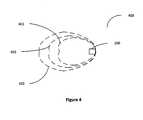
- FIG. 4is a diagram showing coverage provided by the WHS of FIG. 2 for the different switch positions, according to an embodiment of the present invention.
- FIG. 5is a block diagram showing the interference caused by overlap of power lobes when using multiple WHSs, adjacent to one another, having the same frequency spectrum, in a wireless LAN, according to an embodiment of the present invention.
- FIG. 6is a block diagram showing the use of the adjustable power, wireless hot spot sensor, to enable coverage of adjacent areas with reduced interference and fading when using the same frequency spectrum, according to an embodiment of the present invention.
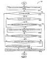
- FIG. 7is a flow chart showing of using the switches to adjust the power output of each of the WHSs to optimize the coverage, according to an embodiment of the present invention.
- a method and a system for providing wireless communication facility with low interference between multiple wireless devices providing hotspot wireless coverage within a local area of an integrated enterprise or integrated home environmentis disclosed.
- the sensor devices implementing hotspotsmay be connected to a PLC LAN and enabled with wireless power output control capability, allowing the coverage of area of each sensor device to be adjusted.
- the power output controlis by a switch which allows the power output to be increased and decreased depending on coverage required and the output of the nearest hotspot.
- the power output levelis indicated on the sensor by LEDs to enable resetting and adjustment.
- the use of power control and elimination of coverage overlapallow multiple hotspots to be used for achieving good connectivity while reducing interferences and noise within hotspots during connection and use.
- FIG. 2is a block diagram 200 of a WHS according to an embodiment of the present invention, enabled to adjust the power level, to three different values, using a toggle switch 205 with LEDs 206 , 207 , and 208 for power level indication.
- the WHS 200comprises the wireless communication processor system 201 , which may have a communication CPU associated with a wireless transmitter-receiver unit for communicating over a network such as 802.11N.
- the communication processor systemalso has receiving and transmitting antennas 202 and 203 , to enable connection to the wireless devices in the vicinity.
- the communication processor system 201is connected to the power level toggle switch 205 that allows the transmitted power levels to be adjusted and connected to power level indicator LEDs 206 , 207 , 208 that may indicate the transmitted power level.
- the WHSmay be connected to a PLC LAN or other type of LAN that is connected to the internet via a gateway to provide the necessary connectivity and communication capability to the outside world for the devices connected via the WHS.
- the WHS 200can be connected to the PLC network through a data communication enabled power switch unit (ETH), described in related U.S. application Ser. No. 13/153,194 described above.
- ETHdata communication enabled power switch unit
- FIG. 3shows a table of settings for toggle switch 205 and the transmitter power delivered by the WHS 200 .
- the transmission power settingis in a “RF power off” state 301 which is indicated by all LEDs 206 , 207 , and 208 being in the off state, that is, with no LEDs 206 , 207 , or 208 powered or lighted.
- Pressing and holding the toggle switch for a 3 second interval while in state 301causes the sensor to transition to “RF power low” 302 state indicated by LED 1 206 in an on state (powered and lighted) while the other two LEDs 207 and 208 are in the off state.
- Pressing and holding the toggle switch for a 3 second interval while in state 302causes the sensor to transition to “RF power medium” 303 state indicated by LED 1 206 and LED 2 207 in an on state while LED 208 is in the off state. Pressing and holding the toggle switch for a 3 second interval while in state 303 causes the sensor to transition to “RF power high” 304 state indicated by all LED's (LED 1 206 , LED 2 207 , and LED 3 208 ) in an on state. Pressing and holding the toggle switch for a 3 second interval while in state 304 returns the sensor to the “RF power off” 301 state.
- the type of switch used and the indication patternare only provided as an example and may modified. Electronic switching based on recognized fading and interference patterns are also possible as an alternate implementation to the switch described, as technology improves and costs come down for automated sensing and control. Also the number of power levels and states of the WHS 200 may be changed to add more power states without prejudice.
- FIG. 4is a diagrammatic representation 400 , which shows the set of exemplary transmission power lobes for the four power level setting selectable using the toggle switch 205 of the WHS 200 .
- the switchis set to RF power off 301 the sensor 200 puts out no transmitted power and no data is transmitted.
- the toggle switch 205is depressed and held for 3 seconds, the LED 1 lights up indicating the low setting for transmitted power as indicated by the power lobes 401 of the transmitted power from the WHS 200 . Further depressing the toggle switch for another 3 seconds changes the power transmission indication to have LED 1 and LED 2 lighted showing RF power transmission of medium power with the coverage provided by the power transmitted shown by the power lobes 402 .
- a third toggle of the switchby 3 seconds lights up the three LEDs, 206 , 207 and 208 , and maximum available RF power is output by the WHS 200 with coverage provided by the power lobes 403 .
- FIG. 5is an exemplary block diagram representation 500 showing the use of a single power level setting for multiple adjacent WHSs, 200 - 1 to 200 - 5 covering rooms or areas 501 to 505 .
- the wireless LAN areais completely covered but the coverage creates power lobe overlaps 510 - 1 to 510 - 4 where the interference and fading occur.
- the phrase “wireless LAN area” as used hereinrefers to a set of points in three-dimensional space in which one or more wireless signals is intended to be received by wireless receivers with sufficient signal strength for use in performing data transactions.
- FIG. 6is an exemplary block diagram representation 600 of the same wireless LAN area as in FIG. 5 with the WHSs 200 - 1 to 200 - 5 which have the power settings adjusted to reduce the power lobe overlaps while still providing coverage within the wireless LAN.
- the method for setting the power levels 403 to 401 of each of the WHSs 200 used to cover the wireless LAN area while providing good coverage with reduced fading and interferenceis shown in flow chart of FIG. 7 .
- the capability to adjust the power of the WHSthe fading and interference caused by overlapping power lobes of adjacent WHSs can be reduced.
- FIG. 7Using the capability to adjust the power of the WHS, the fading and interference caused by overlapping power lobes of adjacent WHSs can be reduced.
- FIG. 6shows the use of WHSs 200 - 1 to 200 - 5 to provide optimum coverage of the wireless LAN area with power settings adjusted to reduce the fading and interference caused by overlapping power lobes when the adjacent WHSs have the same transmission frequency spectrum.
- the exemplary area of the wireless LANcomprising the room blocks 501 to 505 .
- the WHSs 200 - 1 and 200 - 5 in the large room areas 501 and 505are set to the switch condition 304 to deliver the maximum RF power coverage illustrated by power lobes 403 - 1 and 403 - 2 respectively.
- the WHSs in rooms 502 and 504 , 200 - 2 and 200 - 4are set to the switch condition 303 for delivering medium RF power providing coverage illustrated by power lobes 402 - 1 and 402 - 2 respectively.
- the RF power setting of the WHS 200 - 3 in room 500 - 3is set as in switch setting 302 to deliver the low level of RF power 401 - 1 .
- the transmission power lobes overlapis reduced by the selection of the appropriate power level 401 to 403 , thereby reducing the fading and interference when using wireless enabled devices within the wireless LAN.
- FIG. 7is an exemplary and non-limiting flow chart 700 showing how the power level setting of a WHS can be done to have minimum fading and interference when used adjacent to another WHS transmitting on the same frequency spectrum.
- the WHSis connected and powered on and set to the lowest power level providing the lowest RF coverage with the transmitted power lobes (S 701 ).
- the physical coverage providedis checked to see if it is adequate (S 702 ).
- a wireless transmitter-receiver unitis placed at various use locations within the expected coverage area. If the signal strength received at a particular use location is strong enough to support normal data transactions, then the particular use location may be considered to be adequately covered.
- one or more sample data transactionsmay be attempted, and if the data transactions complete successfully, the particular use location may be determined to be adequately covered. For example, an email message may be sent and received or a video streamed to the receiver over the wireless signal between the transmitter and the WHS. If all tested locations within the coverage area have adequate coverage, then the WHS is considered to provide adequate coverage for the wireless LAN area.
- the WHSis considered optimized for use, and the power setting exercise is stopped. (S 709 ). If the coverage is not adequate, that is, one or more required use locations within the expected wireless coverage areas are not covered by the WHS, then the area is checked to see if there are WHS that are adjacent to the current WHS providing coverage (S 703 ). If Adjacent WHSs are present, the required coverage area is checked to see if there are areas of fading and interference within the current coverage area. This may be done by using the wireless transmitter-receiver unit at typical use locations and identifying loss of reception due to fading and interference (S 704 ).
- loss of reception due to fading at typical use locationsmay be determined by measuring signal strength of useful signal at each use location and comparing the signal strength against a threshold signal strength. Fading may be detected when the measured signal strength of usable data intermittently falls below the threshold signal strength. Interference is when the noise level due to multiple transmissions of the received signals becomes large and obscures the usable signal received at a location. Fading and/or interference make the received signal unusable or difficult to understand.
- fading and/or interferencemay be detected by failing to perform a data transaction that succeeds when only the nearest hotspot is transmitting. If fading and interference exist, the power level of the current WHS cannot be increased without adversely impacting the operation of the adjacent WHS unit and hence the current WHS unit is operating at its optimum power level. Further optimization is hence stopped (S 709 ).
- fading and interferenceare determined to exist when fading or interference is detected at any of the tested locations.
- an algorithm, expert system, or human judgmentmay be used to determine if fading and interference exist for the covered area as a whole based on the determinations for each tested location.
- the power setting of the WHSis increased by one setting, providing the next level of RF coverage of the area using the power lobes (S 705 .)
- the coverage areais again checked to see if there are problem areas of fading and interference (S 706 ). If such areas exist with the increased power level then the power level is reduced by one level and further optimization of the power setting of the WHS is stopped (S 708 ).
- the power level settingis checked to see if the power setting is at the highest level or not (S 707 ). If the power setting of the WHS is found to be at the maximum level then the WHS is providing the best coverage it can with minimum fading and interference and so the optimization of the power setting is complete and the optimization is stopped (S 709 ).
- step S 702If the power setting is not at the maximum level then the optimization operation is repeated from step S 702 until the coverage is found to be adequate, the fading and interference impact adjacent WHS coverage, or the WHS power setting reaches maximum power level under which conditions the optimization is complete, and the operation of optimizing the power setting of the WHS is stopped (S 709 ).
Landscapes
- Engineering & Computer Science (AREA)
- Power Engineering (AREA)
- Computer Networks & Wireless Communication (AREA)
- Signal Processing (AREA)
- Mobile Radio Communication Systems (AREA)
Abstract
Description
This application is a continuation-in-part of U.S. patent application Ser. No. 13/153,194 entitled, “A SET OF SENSOR UNITS FOR COMMUNICATION ENABLED FOR STREAMING MEDIA DELIVERY WITH MONITORING AND CONTROL OF POWER USAGE OF CONNECTED APPLIANCES” filed on Jun. 3, 2011; which in turn is a continuation-in-part of U.S. patent application Ser. No. 13/032,454 entitled, “METHOD AND APPARATUS FOR USING PLC-BASED SENSOR UNITS FOR COMMUNICATION AND STREAMING MEDIA DELIVERY, AND FOR MONITORING AND CONTROL OF POWER USAGE OF CONNECTED APPLIANCES, filed Feb. 22, 2011, both of which applications are incorporated herein in their entirety by this reference thereto.
Technical Field
The invention relates to providing wireless coverage within a local area network. More specifically the invention is directed to providing multiple hotspots providing effective area coverage within a wireless local area network with the hotspots spatially separated, but operating simultaneously.
Description of the Background Art
Communications via power lines has been known from early in the 20thcentury. Due to its higher costs and other limitations for extending connectivity, the use of power line communication (PLC) systems has been limited to local area networks (LANs) within homes or offices or, at best, within apartment complexes. PLC has also found a limited number of applications where other types of communication methods do not provide the security and remote connectivity, such as for power line control applications. Basic devices for connecting to the power line for communication and power supply have been designed and used to provide service within LANs. Due to more efficient competing technologies, the infrastructure for PLC never developed to make it a mainstream technology. As a result, more advanced devices for communication using the PLC technology also were never developed.
It is advantageous to identify applications where PLC technology can be optimally used and to develop devices and systems to cater to such applications. One such application that is emerging is providing effective wireless coverage within a local area (wireless LAN area) such as an office, home, small business location, etc. using multiple wireless hotspot sensor (WHS) devices simultaneously.
One problem of having multiple WHS devices or units operating using the same frequency in proximity to each other is interference and fading within the coverage area due to signal overlap from the transmitted signals from multiple WHS devices. Multiple WHS devices become necessary when the wireless LAN area that needs to be covered by wireless connectivity exceeds the capability of a single WHS device.
Prior art technology uses transmitters with different frequencies to eliminate interference when multiple WHS devices have to be provided adjacent to each other within a wireless LAN to have wireless coverage of the wireless LAN area.FIG. 1 is apictorial depiction 100 of prior art. The data from adata store 101 is modulated in themodulators cloud 105. The transmitted modulated data is received and separated into the three frequencies using thefilters adjacent WHS devices adjacent rooms adjacent sensor devices power lobes regions overlap
A WHS system is provided that comprises multiple WHSs in a local area network (LAN) in which each of the multiple sensors transmits using the same frequency spectrum. Each of the WHSs comprises a switch and a power level indicator. The switch on each sensor may be used to adjust the radio frequency (RF) power levels transmitted by the sensor. The power level indicator on each sensor provides an indication of how much power is being used to transmit the wireless signal.
When sensors in close proximity transmit on a common frequency spectrum, the power lobe for one sensor may interfere with the power lobe of another adjacent sensor, causing interference and fading. A method is provided for adjusting the power of each sensor independently so as to optimize coverage of the local area and to minimize interference and fading.
Coverage provided by the power lobe generated by each sensor is measured or checked at usable locations within the expected coverage area using a standard wireless transmitter-receiver unit, and the power is increased to maximize coverage. However, if the power level setting that provides coverage causes interference or fading at the receiver at usable locations, then the power is decreased to minimize the interference or fading. Determining coverage, interference, and fading determines whether to increase, decrease, or maintain the power level for each sensor, thereby providing the best usable wireless coverage within the LAN. (Usable locations are locations within the coverage area where systems and communication devices that connect to the internet typically would be placed.)
In addition, a PLC network may be used to provide a wired connection within a PLC LAN to the WHS devices. The PLC LAN may provide connectivity to appliances connected by wire to it. The use of existing power lines as the source of power and data to the WHS devices eliminates the need and cost of data capable high frequency wiring within the PLC LAN to transport the data to the wireless sensor devices. PLC-connected WHSs providing wireless capability that caters to the needs of communication and streaming media delivery within a home or office may be a beneficial application of PLC technology.
A method and a system for providing wireless communication facility with low interference between multiple wireless devices providing hotspot wireless coverage within a local area of an integrated enterprise or integrated home environment is disclosed. The sensor devices implementing hotspots may be connected to a PLC LAN and enabled with wireless power output control capability, allowing the coverage of area of each sensor device to be adjusted. The power output control is by a switch which allows the power output to be increased and decreased depending on coverage required and the output of the nearest hotspot. The power output level is indicated on the sensor by LEDs to enable resetting and adjustment. The use of power control and elimination of coverage overlap allow multiple hotspots to be used for achieving good connectivity while reducing interferences and noise within hotspots during connection and use.
The type of switch used and the indication pattern are only provided as an example and may modified. Electronic switching based on recognized fading and interference patterns are also possible as an alternate implementation to the switch described, as technology improves and costs come down for automated sensing and control. Also the number of power levels and states of theWHS 200 may be changed to add more power states without prejudice.
If the overall physical coverage provided is adequate, the WHS is considered optimized for use, and the power setting exercise is stopped. (S709). If the coverage is not adequate, that is, one or more required use locations within the expected wireless coverage areas are not covered by the WHS, then the area is checked to see if there are WHS that are adjacent to the current WHS providing coverage (S703). If Adjacent WHSs are present, the required coverage area is checked to see if there are areas of fading and interference within the current coverage area. This may be done by using the wireless transmitter-receiver unit at typical use locations and identifying loss of reception due to fading and interference (S704).
In an embodiment, loss of reception due to fading at typical use locations may be determined by measuring signal strength of useful signal at each use location and comparing the signal strength against a threshold signal strength. Fading may be detected when the measured signal strength of usable data intermittently falls below the threshold signal strength. Interference is when the noise level due to multiple transmissions of the received signals becomes large and obscures the usable signal received at a location. Fading and/or interference make the received signal unusable or difficult to understand. In another embodiment, fading and/or interference may be detected by failing to perform a data transaction that succeeds when only the nearest hotspot is transmitting. If fading and interference exist, the power level of the current WHS cannot be increased without adversely impacting the operation of the adjacent WHS unit and hence the current WHS unit is operating at its optimum power level. Further optimization is hence stopped (S709).
In an embodiment, fading and interference are determined to exist when fading or interference is detected at any of the tested locations. In an alternate embodiment, an algorithm, expert system, or human judgment may be used to determine if fading and interference exist for the covered area as a whole based on the determinations for each tested location.
If no adjacent WHS are found or if adjacent WHS exist but there are no problem areas of fading and interference then the power setting of the WHS is increased by one setting, providing the next level of RF coverage of the area using the power lobes (S705.) The coverage area is again checked to see if there are problem areas of fading and interference (S706). If such areas exist with the increased power level then the power level is reduced by one level and further optimization of the power setting of the WHS is stopped (S708).
If no problem areas of fading and interference are found during the check at S706, the power level setting is checked to see if the power setting is at the highest level or not (S707). If the power setting of the WHS is found to be at the maximum level then the WHS is providing the best coverage it can with minimum fading and interference and so the optimization of the power setting is complete and the optimization is stopped (S709).
If the power setting is not at the maximum level then the optimization operation is repeated from step S702 until the coverage is found to be adequate, the fading and interference impact adjacent WHS coverage, or the WHS power setting reaches maximum power level under which conditions the optimization is complete, and the operation of optimizing the power setting of the WHS is stopped (S709).
In a wireless LAN with multiple WHSs providing the necessary area coverage, it is necessary to check and optimize each of the WHSs as indicated above. This is necessary to achieve a low level of fading and interference while providing adequate coverage of areas within the wireless LAN.
A person skilled-in-the-art would readily appreciate that the invention disclosed herein is described with respect to specific exemplary embodiments of the devices and systems currently used. However, these described embodiments should not be considered limitations on the scope of the invention. Specifically, other implementations of the disclosed invention are envisioned and hence the invention should not be considered to be limited, to the specific embodiments discussed herein above. These units, devices, and systems may be implemented as hardware and/or software implemented and running over hardware as assembly of individual components, as a combination of components and integrated circuits, or SOCs. The invention should not be considered as being limited in scope based on specific block level details, but should be considered on the basis of current and future envisioned functionality.
Although the invention is described herein with reference to the preferred embodiment, one skilled in the art will readily appreciate that other implementations and applications may be substituted for those set forth herein without departing from the spirit and scope of the present invention. Accordingly, the invention should only be limited by the Claims included below.
Claims (18)
1. A wireless hotspot sensor system comprising:
a plurality of wireless hotspot sensors distributed over an area corresponding to a local area network (LAN);
wherein each of the wireless hotspot sensors is enabled to transmit a radio frequency output signal in at least an axial direction outward from the corresponding wireless hotspot sensor, wherein the corresponding radio frequency output signal has a directional power lobe defined in the axial direction, wherein the directional power lobe has an adjustable radio frequency output power level;
wherein each of the wireless hotspot sensors includes a switch for adjusting the radio frequency output power level of the corresponding directional power lobe, and a power level indicator for monitoring the radio frequency output power level of the corresponding directional power lobe;
wherein each of the wireless hotspot sensors are interconnected using a power line communication (PLC) network within the LAN;
wherein the wireless hotspot sensors are spatially separated from each other, and are enabled to simultaneously transmit a common output signal over a common radio frequency spectrum to provide wireless coverage in the LAN;
wherein each of the wireless hotspot sensors is enabled to adjust the corresponding radio frequency output power level responsive to activation of the corresponding switch;
wherein each of the wireless hotspot sensors is further configured to indicate the current corresponding radio frequency output power level through the corresponding power level indicator; and
wherein the radio frequency output power level of each of the wireless hotspot sensors is enabled to provide effective wireless area coverage within the LAN while eliminating or reducing wireless interference and fading due to a first directional power lobe of a first wireless hotspot sensor of the wireless hotspot sensors interfering with a second directional power lobe of a second wireless hotspot sensor of the wireless hotspot sensors, transmitting on the same radio frequency on the LAN.
2. The wireless hotspot sensor system ofclaim 1 , wherein:
the first wireless hotspot sensor is adjusted to transmit at a first radio frequency power level;
the second wireless hotspot sensor is adjusted to transmit at a second radio frequency output power level; and
the first radio frequency power level is different from the second radio frequency output power level.
3. The wireless hotspot sensor system ofclaim 2 ,
wherein the first directional power lobe and the second directional power lobe overlap when operated at a maximum power level; and
wherein the first radio frequency output power level and the second radio frequency output power level are adjusted to values that reduce an overlap of the first directional power lobe and the second directional power lobe.
4. The wireless hotspot sensor system ofclaim 3 , wherein the first and second wireless hotspot sensors are located in adjacent rooms.
5. The wireless hotspot sensor system ofclaim 1 , wherein the plurality of wireless hotspot sensors are adjusted to improve area coverage within the LAN.
6. The wireless hotspot sensor system ofclaim 1 , wherein the wireless hotspot sensors are configured to provide any of communication or streaming of media through the PLC.
7. The wireless hotspot sensor system ofclaim 1 , wherein the switch on each wireless hotspot sensor is a toggle switch, which when pressed, advances the power level by one power level setting.
8. The wireless hotspot sensor system ofclaim 1 , wherein the power level indicator on each wireless hotspot sensor comprises a plurality of LED's, each LED of the plurality of LED's having an “on” or “off” state; and
wherein the radio frequency power level is indicated based on the combination of states of the plurality of LED's.
9. A method comprising:
distributing a plurality of wireless hotspot sensors over an area corresponding to a wireless local area network (LAN), wherein each of the wireless hotspot sensors is enabled to transmit a radio frequency output signal, in at least an axial direction outward from the corresponding wireless hotspot sensor, wherein the corresponding radio frequency output signal has a directional power lobe defined in the axial direction, wherein the directional power lobe has an adjustable radio frequency output power level, wherein each of the wireless hotspot sensors includes a switch for adjusting a radio frequency output power level of the corresponding directional power lobe, and a power level indicator for monitoring the radio frequency output power level of the corresponding directional power lobe, wherein the wireless hotspot sensors are spatially separated from each other;
interconnecting each of the wireless hotspot sensors using a power line communication (PLC) network within the LAN;
simultaneously transmitting a common radio frequency output signal from each of the wireless hotspot sensors over a common radio frequency spectrum to provide wireless coverage within the LAN; and
for each of the wireless hotspot sensors, activating the corresponding switch to adjust the radio frequency output power level of the transmitted radio frequency output signal, wherein the current transmitted radio frequency output power level is indicated by the corresponding power level indicator, to provide effective wireless area coverage within the LAN while eliminating or reducing wireless interference and fading due to a first directional power lobe of a first wireless hotspot sensor of the wireless hotspot sensors interfering with a second directional power lobe of a second wireless hotspot sensor of the wireless hotspot sensors, transmitting on the same radio frequency on the LAN.
10. The method ofclaim 9 , wherein adjusting the radio frequency output power level of the corresponding directional power lobe of each corresponding wireless hotspot sensor comprises:
if the corresponding wireless hotspot sensor is in an “off” state, setting the radio frequency output power level of the corresponding directional power lobe to a lowest power setting;
determining whether or not coverage is adequate;
determining whether or not there are problem areas of fading or interference; and
responsive to determining that coverage is adequate, leaving the radio frequency output power level at the current level.
11. The method ofclaim 10 , wherein determining whether or not coverage is adequate comprises:
selecting a plurality of locations within the wireless LAN area where coverage is required; and
for each location of the plurality of locations determining whether a received output signal generated by the corresponding wireless hotspot sensor is sufficient to enable data transactions to succeed;
wherein determining whether the received output signal is sufficient to enable data transactions to succeed comprises using a wireless transmitter-receiver to perform any of:
attempting to perform a data transaction, and responsive to the data transaction succeeding, determining that the coverage at said each location is adequate; or
measuring signal strength of the received signal, comparing the output signal strength against a signal strength threshold, and responsive to determining that the signal strength is above the signal strength threshold, determining that the coverage at said each location is adequate.
12. The method ofclaim 10 , wherein adjusting the radio frequency output power level of the corresponding directional power lobe of each corresponding wireless hotspot sensor further comprises:
responsive to determining that coverage is not adequate and that there are no problem areas of fading or interference, increasing the output power level for each wireless hotspot sensor.
13. The method ofclaim 12 , wherein adjusting the radio frequency output power level of the corresponding directional power lobe of each corresponding wireless hotspot sensor further comprises:
determining whether or not increasing the output power level has resulted in areas of interference or fading; and
responsive to determining that increasing the transmitted radio frequency power level has resulted in areas of interference or fading, decreasing the transmitted radio frequency output power level to a previous level.
14. The method ofclaim 12 , wherein adjusting the transmitted radio frequency output power level of the corresponding directional power lobe of each wireless hotspot sensor further comprises:
determining whether or not the increasing the transmitted radio frequency output power level has resulted in areas of interference or fading;
responsive to determining that increasing the transmitted radio frequency output power level has not resulted in areas of interference or fading:
further determining whether or not the transmitted radio frequency output power level has reached the highest power level;
responsive to determining that the transmitted radio frequency output power level has reached the highest power level, leaving the transmitted radio frequency output power level at the highest power level; and
responsive to determining that the transmitted radio frequency output power level has not reached the highest power level, repeating the method ofclaim 10 with the current power level.
15. The method ofclaim 9 , wherein the wireless hotspot sensors provide connectivity for any of communication or streaming of media through the PLC.
16. A method comprising:
distributing a plurality of wireless hotspot sensors over an area corresponding to a wireless local area network (LAN), wherein each of the wireless hotspot sensors is enabled to transmit a radio frequency output signal in at least an axial direction outward from the corresponding wireless hotspot sensor, wherein the corresponding radio frequency output signal has a directional power lobe defined in the axial direction, wherein the directional power lobe has an adjustable radio frequency output power level, wherein each of the wireless hotspot sensors includes a switch for adjusting a radio frequency output power level for the corresponding directional power lobe, and a power level indicator for monitoring the radio frequency output power level of the corresponding directional power lobe, wherein each of the wireless hotspot sensors are spatially separated from each other;
interconnecting each of the wireless hotspot sensors using a power line communication (PLC) network within the wireless LAN;
simultaneously transmitting a common radio frequency output signal from each of the wireless hotspot sensors over a common radio frequency spectrum to provide wireless coverage within the wireless LAN;
obtaining a first set of data including locations within the wireless LAN of fading and interference of a first directional power lobe generated by a particular wireless hotspot sensor in the presence of adjacent wireless hotspot sensors that are simultaneously transmitting on the common radio frequency;
based on the first set of data, using the switch on the particular wireless hotspot sensor to adjust the radio frequency output power level of the corresponding transmitted output signal;
obtaining a subsequent set of data including locations within the wireless LAN of fading and interference of a second directional power lobe generated by the particular wireless hotspot sensor after the adjustment is made;
based on the second set of data, using the switch on the particular wireless hotspot sensor to adjust the radio frequency output power level of the corresponding transmitted output signal; and
repeating the method for each of the other wireless hotspot sensors to provide effective wireless area coverage within the wireless LAN while eliminating or reducing wireless interference and fading due to the first directional power lobe interfering with the second directional power lobe, on the common radio frequency on the wireless LAN.
17. The method ofclaim 16 wherein the wireless hotspot sensors receive power and data through the PLC.
18. The method ofclaim 16 wherein the locations within the wireless LAN area of fading and interference is determined by:
selecting a plurality of locations within the wireless LAN area where coverage is required;
for each location of the plurality of locations determining whether a radio frequency output signal generated by the corresponding wireless hotspot sensor is sufficient to enable data transactions to succeed;
wherein determining whether a radio frequency output signal is sufficient to enable data transactions to succeed comprises using a wireless transmitter-receiver to perform at least one of:
attempting to perform a pre-determined data transaction, and responsive to the data transaction failing, determining that said each location is a location of fading and interference; or
measuring a signal strength of a received output signal, comparing the output signal strength against a pre-determined threshold, and responsive to determining that the signal strength is below the pre-determined threshold, determining that said each location is a location of fading and interference.
Priority Applications (1)
| Application Number | Priority Date | Filing Date | Title |
|---|---|---|---|
| US13/725,144US9736789B2 (en) | 2011-02-22 | 2012-12-21 | Power line communication-based local hotspot with wireless power control capability |
Applications Claiming Priority (3)
| Application Number | Priority Date | Filing Date | Title |
|---|---|---|---|
| US13/032,454US8755946B2 (en) | 2011-02-22 | 2011-02-22 | Method and apparatus for using PLC-based sensor units for communication and streaming media delivery, and for monitoring and control of power usage of connected appliances |
| US13/153,194US8364326B2 (en) | 2011-02-22 | 2011-06-03 | Set of sensor units for communication enabled for streaming media delivery with monitoring and control of power usage of connected appliances |
| US13/725,144US9736789B2 (en) | 2011-02-22 | 2012-12-21 | Power line communication-based local hotspot with wireless power control capability |
Related Parent Applications (1)
| Application Number | Title | Priority Date | Filing Date |
|---|---|---|---|
| US13/153,194Continuation-In-PartUS8364326B2 (en) | 2011-02-22 | 2011-06-03 | Set of sensor units for communication enabled for streaming media delivery with monitoring and control of power usage of connected appliances |
Publications (2)
| Publication Number | Publication Date |
|---|---|
| US20130182588A1 US20130182588A1 (en) | 2013-07-18 |
| US9736789B2true US9736789B2 (en) | 2017-08-15 |
Family
ID=48779889
Family Applications (1)
| Application Number | Title | Priority Date | Filing Date |
|---|---|---|---|
| US13/725,144Expired - Fee RelatedUS9736789B2 (en) | 2011-02-22 | 2012-12-21 | Power line communication-based local hotspot with wireless power control capability |
Country Status (1)
| Country | Link |
|---|---|
| US (1) | US9736789B2 (en) |
Cited By (1)
| Publication number | Priority date | Publication date | Assignee | Title |
|---|---|---|---|---|
| US10602462B1 (en) | 2018-11-30 | 2020-03-24 | International Business Machines Corporation | Hotspot channel congestion mitigation |
Families Citing this family (1)
| Publication number | Priority date | Publication date | Assignee | Title |
|---|---|---|---|---|
| US20150057966A1 (en)* | 2013-08-23 | 2015-02-26 | Xband Technology Corporation | Jump Sensor Device |
Citations (166)
| Publication number | Priority date | Publication date | Assignee | Title |
|---|---|---|---|---|
| US5090024A (en)* | 1989-08-23 | 1992-02-18 | Intellon Corporation | Spread spectrum communications system for networks |
| US5553072A (en)* | 1995-01-30 | 1996-09-03 | Northrop Grumman Corporation | Communication apparatus and method |
| US5572438A (en)* | 1995-01-05 | 1996-11-05 | Teco Energy Management Services | Engery management and building automation system |
| US5630204A (en) | 1995-05-01 | 1997-05-13 | Bell Atlantic Network Services, Inc. | Customer premise wireless distribution of broad band signals and two-way communication of control signals over power lines |
| US5999612A (en)* | 1997-05-27 | 1999-12-07 | International Business Machines Corporation | Integrated telephony and data services over cable networks |
| US6252883B1 (en)* | 1997-02-27 | 2001-06-26 | Aloha Networks, Inc. | Home and personal data services overlay communications system |
| US20020023267A1 (en) | 2000-05-31 | 2002-02-21 | Hoang Khoi Nhu | Universal digital broadcast system and methods |
| US20020026532A1 (en) | 2000-08-31 | 2002-02-28 | Ryuichi Maeda | Protocol conversion connector of communication network-adapted type and indoor communication network system |
| US6378131B2 (en)* | 1996-11-15 | 2002-04-23 | Itt Manufacturing Enterprises, Inc. | Local upstream hub for one-way cable system data/video/services requests |
| US20020114336A1 (en) | 2001-02-21 | 2002-08-22 | Yu-Chun Chow | Gateway apparatus for performing communication between WAN and LAN |
| US6453687B2 (en) | 2000-01-07 | 2002-09-24 | Robertshaw Controls Company | Refrigeration monitor unit |
| US20020165943A1 (en) | 2000-05-31 | 2002-11-07 | Hoang Khoi Nhu | Universal STB architectures and control methods |
| US20030050737A1 (en) | 2001-09-10 | 2003-03-13 | Robert Osann | Energy-smart home system |
| US6553418B1 (en)* | 1999-01-02 | 2003-04-22 | Daniel J. Collins | Energy information and control system |
| US6633823B2 (en)* | 2000-07-13 | 2003-10-14 | Nxegen, Inc. | System and method for monitoring and controlling energy usage |
| US20040022304A1 (en) | 2002-06-21 | 2004-02-05 | John Santhoff | Ultra-wideband communication though local power lines |
| US20040070912A1 (en) | 2002-09-30 | 2004-04-15 | Amperion, Inc. | Method and system to increase the throughput of a communications system that uses an electrical power distribution system as a communications pathway |
| US20040106412A1 (en) | 2002-08-08 | 2004-06-03 | Rajiv Laroia | Method of creating and utilizing diversity in multiple carrier communication system |
| US20040139472A1 (en) | 1997-03-21 | 2004-07-15 | Thierry Furet | Transmission and reception of television programmes and other data |
| US20040138786A1 (en) | 1994-12-30 | 2004-07-15 | Power Measurement, Ltd. | Method and system for master slave protocol communication in an intelligent electronic device |
| US20040148632A1 (en) | 2003-01-23 | 2004-07-29 | Ji-Hyun Park | Remote controller and set-top-box therefor |
| US20040155985A1 (en) | 2001-06-05 | 2004-08-12 | Frank Dethier | Interface unit |
| US20040193329A1 (en) | 1994-12-30 | 2004-09-30 | Ransom Douglas S. | System and method for securing energy management systems |
| US20040203989A1 (en)* | 2002-09-12 | 2004-10-14 | Broadcom Corporation | Using location information to control transmission signal levels of wireless devices |
| US20040212481A1 (en) | 2000-05-23 | 2004-10-28 | Satius, Inc. | High frequency network multiplexed communications over various lines using multiple modulated carrier frequencies |
| US6826607B1 (en) | 1999-10-06 | 2004-11-30 | Sensoria Corporation | Apparatus for internetworked hybrid wireless integrated network sensors (WINS) |
| US6834045B1 (en)* | 2000-07-11 | 2004-12-21 | Lappetelaeinen Antti | Assembly, and associated method, for facilitating frequency allocations in a radio communications system to attain statistical spreading of electromagnetic energy |
| US20050008345A1 (en) | 2003-07-01 | 2005-01-13 | Choi Yong-Hun | Digital audio/video apparatus and method that can perform additional operations |
| US20050018766A1 (en) | 2003-07-21 | 2005-01-27 | Sony Corporation And Sony Electronics, Inc. | Power-line communication based surveillance system |
| US6854059B2 (en) | 2000-06-07 | 2005-02-08 | Conexant Systems, Inc. | Method and apparatus for medium access control in powerline communication network systems |
| US20050030968A1 (en)* | 2003-08-07 | 2005-02-10 | Skypilot Network, Inc. | Communication protocol for a wireless mesh architecture |
| US6882709B1 (en) | 1999-04-14 | 2005-04-19 | General Instrument Corporation | Enhanced broadband telephony services |
| US20050160467A1 (en) | 2004-01-19 | 2005-07-21 | Alcatel | Multimedia telecommunication system with a multipurpose multimedia device |
| US20050157215A1 (en) | 2003-09-11 | 2005-07-21 | Echostar Techonologies Corporation | Method and apparatus for detecting an inactive channel selecting resource in a television converter |
| US6934862B2 (en) | 2000-01-07 | 2005-08-23 | Robertshaw Controls Company | Appliance retrofit monitoring device with a memory storing an electronic signature |
| US20050184867A1 (en) | 2001-09-10 | 2005-08-25 | Osann Robert Jr. | Home intrusion confrontation avoidance system |
| US20050207079A1 (en) | 2004-03-17 | 2005-09-22 | Tiller David S | System and apparatus for a multifunctional powerline carrier device with data management and power surge protector |
| US6956464B2 (en) | 2003-05-14 | 2005-10-18 | Abocom Systems, Inc. | Power apparatus having built-in powerline networking adapter |
| US6961641B1 (en) | 1994-12-30 | 2005-11-01 | Power Measurement Ltd. | Intra-device communications architecture for managing electrical power distribution and consumption |
| US20050272402A1 (en) | 2004-05-10 | 2005-12-08 | Alon Ferentz | Method for rapid port power reduction |
| US6988025B2 (en)* | 2000-11-28 | 2006-01-17 | Power Measurement Ltd. | System and method for implementing XML on an energy management device |
| US20060049694A1 (en) | 2004-09-03 | 2006-03-09 | Lawrence Kates | Method and apparatus for load management in an electric power system |
| US7020701B1 (en) | 1999-10-06 | 2006-03-28 | Sensoria Corporation | Method for collecting and processing data using internetworked wireless integrated network sensors (WINS) |
| US20060083206A1 (en)* | 2004-10-19 | 2006-04-20 | Samsung Electronics Co., Ltd. | Sub-access point, system, and method for adjusting power of transmission signal |
| US20060088149A1 (en) | 2004-10-27 | 2006-04-27 | Samsung Electronics Co., Ltd. | Set-top-box apparatus and method of providing VoIP service information |
| US20060099954A1 (en)* | 2004-11-11 | 2006-05-11 | M/A Com Inc. | Wireless communication network |
| US20060168624A1 (en) | 2004-11-22 | 2006-07-27 | John Carney | Method and system for delivering enhanced TV content |
| US7113763B2 (en) | 2002-06-03 | 2006-09-26 | Nokia Corporation | Bluetooth access point and remote bluetooth modules for powerline based networking |
| US20060222086A1 (en) | 2005-03-29 | 2006-10-05 | Frye Bernard F Jr | Multi-unit power line communications system and method |
| US20060227884A1 (en) | 2005-04-08 | 2006-10-12 | Matsushita Electric Industrial Co., Ltd. | Relay apparatus and electric appliance |
| US7136936B2 (en) | 2003-10-03 | 2006-11-14 | Asoka Usa Corporation | Method and system for virtual powerline local area networks |
| US7142094B1 (en) | 2002-02-20 | 2006-11-28 | Current Grid, Llc | Last leg power grid high-speed data transmitter and receiver structures |
| US7173938B1 (en) | 2001-05-18 | 2007-02-06 | Current Grid, Llc | Method and apparatus for processing outbound data within a powerline based communication system |
| US20070043477A1 (en) | 2002-03-28 | 2007-02-22 | Ehlers Gregory A | System and method of controlling an HVAC system |
| US20070061487A1 (en) | 2005-02-01 | 2007-03-15 | Moore James F | Systems and methods for use of structured and unstructured distributed data |
| US7194528B1 (en) | 2001-05-18 | 2007-03-20 | Current Grid, Llc | Method and apparatus for processing inbound data within a powerline based communication system |
| US20070130598A1 (en) | 2005-12-01 | 2007-06-07 | Electronics And Telecommunications Research Institute | Digital satellite broadcasting set-top box, and home network control system employing the same |
| US7231280B2 (en) | 2004-12-14 | 2007-06-12 | Costa Enterprises, L.L.C. | Dynamic control system for power sub-network |
| US7231281B2 (en) | 2004-12-14 | 2007-06-12 | Costa Enterprises, L.L.C. | Dynamic control system for power sub-network |
| US20070132579A1 (en) | 2005-12-12 | 2007-06-14 | Lg Electronics Inc. | Electric device with wireless communication module |
| US7245472B2 (en) | 2001-05-18 | 2007-07-17 | Curretn Grid, Llc | Medium voltage signal coupling structure for last leg power grid high-speed data network |
| US20070183543A1 (en) | 2006-02-03 | 2007-08-09 | Yung-Wei Lu | Power line communication (PLC) noise isolation device |
| US20070204286A1 (en) | 2006-02-28 | 2007-08-30 | Sony Electronics Inc. | System and method for transcoding signal content |
| US20070213879A1 (en) | 2006-03-09 | 2007-09-13 | Sony Corporation | Systems and methods for use in providing local power line communication |
| US20070233323A1 (en) | 2006-04-04 | 2007-10-04 | Panduit Corp. | Building automation system controller |
| US20070229231A1 (en) | 2005-10-03 | 2007-10-04 | Hurwitz Jonathan E D | Multi-Wideband Communications over Multiple Mediums within a Network |
| US20070250900A1 (en) | 2006-04-07 | 2007-10-25 | Andrew Marcuvitz | Media gateway and server |
| US7319717B2 (en) | 2005-06-28 | 2008-01-15 | International Broadband Electric Communications, Inc. | Device and method for enabling communications signals using a medium voltage power line |
| US7345998B2 (en) | 2004-12-15 | 2008-03-18 | Smart Labs, Inc. | Mesh network of intelligent devices communicating via powerline and radio frequency |
| US7363398B2 (en) | 2002-08-16 | 2008-04-22 | The Board Of Trustees Of The Leland Stanford Junior University | Intelligent total access system |
| US20080106146A1 (en) | 2004-11-02 | 2008-05-08 | Lg Electronics Inc. | Management System for In-House Power Quantity Consumed |
| US20080130640A1 (en) | 2005-10-03 | 2008-06-05 | Jonathan Ephraim David Hurwitz | Multi-Wideband Communications over Multiple Mediums |
| US20080137572A1 (en) | 2006-12-08 | 2008-06-12 | Wan-Ki Park | Apparatus and method for controlling home appliances using zigbee wireless communication |
| US20080195562A1 (en) | 2007-02-09 | 2008-08-14 | Poweronedata Corporation | Automated meter reading system |
| US7423546B1 (en) | 1999-08-20 | 2008-09-09 | Indesit Comapny S.P.A. | Device, system and method for monitoring a household electric appliance |
| US20080221737A1 (en) | 2007-03-08 | 2008-09-11 | Kurt Josephson | Networked electrical interface |
| US20080259888A1 (en)* | 2007-04-18 | 2008-10-23 | Sony Corporation | Communications system and communication apparatus |
| US7444401B1 (en) | 2002-11-18 | 2008-10-28 | Arkion Systems Llc | Method and apparatus for inexpensively monitoring and controlling remotely distributed appliances |
| US7463986B2 (en) | 2002-10-25 | 2008-12-09 | Hudson Bay Wireless Llc | Electrical power metering system |
| US20080317070A1 (en) | 2000-04-17 | 2008-12-25 | Adaptive Networks, Inc. | Power line communication network |
| US20090093916A1 (en) | 2003-10-15 | 2009-04-09 | Ice Energy, Inc. | Utility managed virtual power plant utilizing aggregated thermal energy storage |
| US20090099629A1 (en) | 2007-10-12 | 2009-04-16 | Medivance Incorporated | System and method for patient temperature control |
| US20090117915A1 (en) | 2007-11-06 | 2009-05-07 | Samsung Electro-Mechanics Co., Ltd. | Mobile device and method of obtaining position data of the same |
| US20090135848A1 (en)* | 2007-11-26 | 2009-05-28 | Asoka Usa Corporation | System and Method for Repeater in a Power Line Network |
| US20090175321A1 (en)* | 2008-01-08 | 2009-07-09 | Sony Corporation | Communication system and communication apparatus |
| US20090182862A1 (en)* | 2008-01-10 | 2009-07-16 | Allan Thomson | Optimization for wireless access point management |
| US20090187499A1 (en) | 2008-01-21 | 2009-07-23 | David Mulder | System, Method and Computer Program Product for Providing Demand Response Functionality |
| US20090190553A1 (en)* | 2006-06-06 | 2009-07-30 | Yoichi Masuda | Radio communication system, radio terminal, base station, and base station search method |
| US20090195349A1 (en) | 2008-02-01 | 2009-08-06 | Energyhub | System and method for home energy monitor and control |
| US20090225679A1 (en)* | 2002-01-11 | 2009-09-10 | Broadcom Corporation | Reconfiguration of a communication system |
| US20090262665A1 (en) | 2008-04-22 | 2009-10-22 | Samsung Electronics., Ltd. | Communication system using zigbee and method of controlling the same |
| US20100027599A1 (en) | 2008-07-30 | 2010-02-04 | Anthony Di Chiro | Power Line Communications Adapter |
| US20100070217A1 (en) | 2008-09-18 | 2010-03-18 | Adapta Strategy | System and method for monitoring and management of utility usage |
| US20100076701A1 (en) | 2004-04-09 | 2010-03-25 | Loadstar Sensors, Inc. | Resistive force sensing device and method with an advanced communication interface |
| US20100075661A1 (en)* | 2008-09-25 | 2010-03-25 | Aihua Edward Li | Method and System for Tuning and Self-Monitoring of Wireless Networks |
| US7688841B2 (en) | 2003-07-09 | 2010-03-30 | Mosaid Technologies Incorporated | Modular outlet |
| US20100082499A1 (en) | 2008-03-28 | 2010-04-01 | Luff Robert A | Systems, methods, and apparatus to generate an energy consumption index |
| US20100094475A1 (en) | 2007-10-14 | 2010-04-15 | Gilbert Masters | Electrical Energy Usage Monitoring System |
| US20100095335A1 (en) | 2008-10-15 | 2010-04-15 | At&T Services, Inc. | System and method for distributing video data over an electrical power line |
| US20100091745A1 (en)* | 2008-10-10 | 2010-04-15 | Nortel Networks, Limited | Coverage optimisation for wireless networks |
| US7701331B2 (en) | 2006-06-12 | 2010-04-20 | Tran Bao Q | Mesh network door lock |
| US20100097528A1 (en) | 2008-10-17 | 2010-04-22 | Samsung Electronics Co., Ltd. | Apparatus and method for receiving two modes of broadcasts using one tuner in set-top-box |
| US20100102987A1 (en) | 2001-05-18 | 2010-04-29 | Heng Lou | Power Line Communication Device having Virtual Local Area Network Functionality |
| US20100105336A1 (en)* | 2008-10-24 | 2010-04-29 | Qualcomm Incorporated | Active set management with hotspot carriers |
| US20100106342A1 (en) | 2008-10-28 | 2010-04-29 | Korea Electric Power Corporation | Day-ahead load reduction system based on customer baseline load |
| US20100121968A1 (en) | 2008-11-11 | 2010-05-13 | Qwebl, Inc. | System and method for automating operations of household systems from remote applications |
| US20100128711A1 (en)* | 2001-11-28 | 2010-05-27 | John Klein | Transmit power control for mobile unit |
| US20100138066A1 (en) | 2008-11-14 | 2010-06-03 | Thinkeco Power Inc. | System and method of democratizing power to create a meta-exchange |
| US7734380B2 (en)* | 1997-02-12 | 2010-06-08 | Power Measurement Ltd. | Push communications architecture for intelligent electronic devices |
| US7738999B2 (en) | 2001-08-15 | 2010-06-15 | Hunt Technologies, Inc. | System for controlling electrically-powered devices in an integrated wireless network |
| US20100156666A1 (en) | 2008-12-24 | 2010-06-24 | Kwangsoon Choi | System and methods for monitoring energy consumption and reducing standby power |
| US20100169940A1 (en) | 2008-12-29 | 2010-07-01 | Embarq Holdings Company, Llc | Method and apparatus for communicating data via a cable card |
| US7751795B2 (en) | 2002-01-25 | 2010-07-06 | Ksc Industries Incorporated | Wired, wireless, infrared, and powerline audio entertainment systems |
| US20100182160A1 (en) | 2009-01-21 | 2010-07-22 | Ming-Wei Lu | Remote control with passive RFID tag and Zigbee arrangement |
| US20100204850A1 (en) | 2007-06-26 | 2010-08-12 | Eandis | Distributor power line communication system |
| US7778152B2 (en) | 2008-02-14 | 2010-08-17 | Asoka Usa Corporation | Non-intrusive method and system for coupling powerline communications signals to a powerline network |
| US20100207728A1 (en) | 2009-02-18 | 2010-08-19 | General Electric Corporation | Energy management |
| US20100217449A1 (en) | 2009-02-20 | 2010-08-26 | International Business Machines Corporation | System and method to manage power consumption |
| US20100228601A1 (en) | 2008-10-01 | 2010-09-09 | Silver Spring Networks, Inc. | Method and System of Applying Environmental Incentives |
| US20100233975A1 (en) | 2009-03-10 | 2010-09-16 | Minebea Co., Ltd. | Automated power control to optimize power consumption and improved wireless connection |
| US20100250497A1 (en) | 2007-01-05 | 2010-09-30 | Redlich Ron M | Electromagnetic pulse (EMP) hardened information infrastructure with extractor, cloud dispersal, secure storage, content analysis and classification and method therefor |
| US7825793B1 (en) | 2006-06-21 | 2010-11-02 | Sunrise Technologies, Inc. | Remote monitoring and control system |
| US7848759B2 (en)* | 2001-11-08 | 2010-12-07 | Kim Byoung-Jo J | Frequency assignment for multi-cell IEEE 802.11 wireless networks |
| US20100332164A1 (en) | 2008-02-05 | 2010-12-30 | Indesit Company S.P.A. | Communication device for household electric appliances and monitoring system using said device |
| US20100327766A1 (en) | 2006-03-28 | 2010-12-30 | Recker Michael V | Wireless emergency lighting system |
| US20110035491A1 (en) | 1999-10-06 | 2011-02-10 | Gelvin David C | Method for Internetworked Hybrid Wireless Integrated Network Sensors (WINS) |
| US20110040785A1 (en) | 2008-05-07 | 2011-02-17 | PowerHouse dynamics, Inc. | System and method to monitor and manage performance of appliances |
| US20110037589A1 (en) | 2009-08-11 | 2011-02-17 | Rong Zhi Xin Science and Technology Development (Beijing) Co., Ltd. | Wireless monitoring system and method |
| US20110054710A1 (en) | 2009-08-21 | 2011-03-03 | Imes Kevin R | Energy management system and method |
| US20110054700A1 (en) | 2009-08-25 | 2011-03-03 | Jetlun Corporation | System for using a plurality of remote sensing devices for energy management |
| US20110066300A1 (en) | 2009-09-11 | 2011-03-17 | General Electric Company | Method and system for demand response in a distribution network |
| US20110077758A1 (en) | 2007-05-24 | 2011-03-31 | Alexander Bach Tran | Smart air ventilation system |
| US20110082599A1 (en) | 2009-10-06 | 2011-04-07 | Makarand Shinde | Optimizing Utility Usage by Smart Monitoring |
| US20110087522A1 (en) | 2009-10-08 | 2011-04-14 | International Business Machines Corporation | Method for deploying a probing environment for provisioned services to recommend optimal balance in service level agreement user experience and environmental metrics |
| US20110089752A1 (en) | 2008-02-21 | 2011-04-21 | Cnh Italia Spa | Electronically Controlled Brake Apparatus for Tractors |
| US20110093221A1 (en) | 2009-10-16 | 2011-04-21 | Savraj Singh Dhanjal | System to monitor energy use |
| US20110121654A1 (en) | 2006-03-28 | 2011-05-26 | Recker Michael V | Remote switch sensing in lighting devices |
| US7961111B2 (en) | 2007-12-26 | 2011-06-14 | Audiovox Corporation | Home control protection system |
| US20110147190A1 (en)* | 2009-12-21 | 2011-06-23 | Lutron Electronics Co., Inc. | Control Button Having a Single Return Spring for Multiple Buttons |
| US20110161251A1 (en) | 2005-01-18 | 2011-06-30 | Carey Margaret M | Method and System for Tracking and Budgeting Energy Usage |
| US20110184581A1 (en) | 2008-08-27 | 2011-07-28 | Herman Miller, Inc. | Energy Distribution Management System |
| US20110196547A1 (en) | 2010-02-09 | 2011-08-11 | Jong Soo Park | Apparatus for controlling a power using a smart device and method thereof |
| US20110202190A1 (en) | 2010-02-15 | 2011-08-18 | General Electric Company | Low cost and flexible energy management system defined in a single unitary housing |
| US20110215736A1 (en) | 2010-03-08 | 2011-09-08 | Horbst Joseph E | Method and system for lighting control and monitoring |
| US20110231320A1 (en) | 2009-12-22 | 2011-09-22 | Irving Gary W | Energy management systems and methods |
| US20110238235A1 (en) | 2011-02-22 | 2011-09-29 | Asoka Usa Corporation | Set Of Sensor Units For Communication Enabled For Streaming Media Delivery With Monitoring And Control Of Power Usage Of Connected Appliances |
| US20110264286A1 (en) | 2010-04-27 | 2011-10-27 | Jong Soo Park | Smart control device |
| US20110264291A1 (en) | 2010-04-26 | 2011-10-27 | Accenture Global Services Gmbh | Methods and Systems for Analyzing Energy Usage |
| US20110263277A1 (en)* | 2010-04-23 | 2011-10-27 | Fabiel Zuniga Gallegos | Method and system for radio frequency coverage prediction in a multi-level wireless network |
| US20110271317A1 (en) | 2011-02-22 | 2011-11-03 | Xia Mingyao | Set-Top-Box Having a Built-In Master Node That Provides an External Interface for Communication and Control in a Power-Line-Based Residential Communication System |
| US20110307109A1 (en) | 2010-05-27 | 2011-12-15 | Sri-Jayantha Sri M | Smarter-Grid: Method to Forecast Electric Energy Production and Utilization Subject to Uncertain Environmental Variables |
| US20120001548A1 (en) | 2008-11-26 | 2012-01-05 | Wireless Environment, Llc | Switch sensing emergency lighting device |
| US20120053737A1 (en) | 2011-01-06 | 2012-03-01 | General Electric Company | Home energy management system incorporating a pool pump |
| US20120066023A1 (en) | 2011-02-22 | 2012-03-15 | Xia Mingyao | Green Energy Database Including Verifiable Information for Implementing a National Level Green Energy Policy |
| US20120095610A1 (en) | 2007-03-14 | 2012-04-19 | Zonit Structured Solutions, Llc. | Smart nema outlets and associated networks |
| US20120109395A1 (en) | 2010-10-28 | 2012-05-03 | General Electric Company | Controlling multiple smart appliances with a single communication interface |
| US8290628B2 (en) | 2010-07-23 | 2012-10-16 | Lg Electronics Inc. | Air conditioner and method for controlling the same |
| US20120265357A1 (en) | 2011-04-13 | 2012-10-18 | Fujitsu Limited | Measure Energy Consumption and Determine Energy-Consumption Patterns for Electricity-Consuming Devices |
| US20120271472A1 (en) | 2011-04-22 | 2012-10-25 | Joulex, Inc. | System and methods for sustainable energy management, monitoring, and control of electronic devices |
| US8306634B2 (en) | 2008-12-23 | 2012-11-06 | Samsung Electronics Co., Ltd. | Adaptive and user location-based power saving system |
| US20130013234A1 (en) | 2011-07-08 | 2013-01-10 | Siemens Schweiz Ag | Distributed Energy Grid Management |
| US20130054044A1 (en) | 2011-08-22 | 2013-02-28 | Cisco Technology, Inc. | Adaptive control of power grid operations based on energy profiles |
| US20130116846A1 (en) | 2010-05-21 | 2013-05-09 | American Power Conversion Corporation | Method and apparatus for controlling distribution of power |
| US20130158911A1 (en) | 2010-06-25 | 2013-06-20 | Enmodus Limited | Quantised monitoring of power-consumption |
| US8503150B2 (en) | 2008-03-17 | 2013-08-06 | Universiti Malaysia Pahang | Electrical interface protecting apparatus |
| US8644166B2 (en) | 2011-06-03 | 2014-02-04 | Asoka Usa Corporation | Sensor having an integrated Zigbee® device for communication with Zigbee® enabled appliances to control and monitor Zigbee® enabled appliances |
- 2012
- 2012-12-21USUS13/725,144patent/US9736789B2/ennot_activeExpired - Fee Related
Patent Citations (196)
| Publication number | Priority date | Publication date | Assignee | Title |
|---|---|---|---|---|
| US5090024A (en)* | 1989-08-23 | 1992-02-18 | Intellon Corporation | Spread spectrum communications system for networks |
| US20040138786A1 (en) | 1994-12-30 | 2004-07-15 | Power Measurement, Ltd. | Method and system for master slave protocol communication in an intelligent electronic device |
| US6990395B2 (en)* | 1994-12-30 | 2006-01-24 | Power Measurement Ltd. | Energy management device and architecture with multiple security levels |
| US6961641B1 (en) | 1994-12-30 | 2005-11-01 | Power Measurement Ltd. | Intra-device communications architecture for managing electrical power distribution and consumption |
| US20040193329A1 (en) | 1994-12-30 | 2004-09-30 | Ransom Douglas S. | System and method for securing energy management systems |
| US5572438A (en)* | 1995-01-05 | 1996-11-05 | Teco Energy Management Services | Engery management and building automation system |
| US5553072A (en)* | 1995-01-30 | 1996-09-03 | Northrop Grumman Corporation | Communication apparatus and method |
| US5630204A (en) | 1995-05-01 | 1997-05-13 | Bell Atlantic Network Services, Inc. | Customer premise wireless distribution of broad band signals and two-way communication of control signals over power lines |
| US6378131B2 (en)* | 1996-11-15 | 2002-04-23 | Itt Manufacturing Enterprises, Inc. | Local upstream hub for one-way cable system data/video/services requests |
| US7734380B2 (en)* | 1997-02-12 | 2010-06-08 | Power Measurement Ltd. | Push communications architecture for intelligent electronic devices |
| US6252883B1 (en)* | 1997-02-27 | 2001-06-26 | Aloha Networks, Inc. | Home and personal data services overlay communications system |
| US20040139472A1 (en) | 1997-03-21 | 2004-07-15 | Thierry Furet | Transmission and reception of television programmes and other data |
| US5999612A (en)* | 1997-05-27 | 1999-12-07 | International Business Machines Corporation | Integrated telephony and data services over cable networks |
| US6553418B1 (en)* | 1999-01-02 | 2003-04-22 | Daniel J. Collins | Energy information and control system |
| US6882709B1 (en) | 1999-04-14 | 2005-04-19 | General Instrument Corporation | Enhanced broadband telephony services |
| US7423546B1 (en) | 1999-08-20 | 2008-09-09 | Indesit Comapny S.P.A. | Device, system and method for monitoring a household electric appliance |
| US6826607B1 (en) | 1999-10-06 | 2004-11-30 | Sensoria Corporation | Apparatus for internetworked hybrid wireless integrated network sensors (WINS) |
| US20110035491A1 (en) | 1999-10-06 | 2011-02-10 | Gelvin David C | Method for Internetworked Hybrid Wireless Integrated Network Sensors (WINS) |
| US7020701B1 (en) | 1999-10-06 | 2006-03-28 | Sensoria Corporation | Method for collecting and processing data using internetworked wireless integrated network sensors (WINS) |
| US6453687B2 (en) | 2000-01-07 | 2002-09-24 | Robertshaw Controls Company | Refrigeration monitor unit |
| US6934862B2 (en) | 2000-01-07 | 2005-08-23 | Robertshaw Controls Company | Appliance retrofit monitoring device with a memory storing an electronic signature |
| US20080317070A1 (en) | 2000-04-17 | 2008-12-25 | Adaptive Networks, Inc. | Power line communication network |
| US20040212481A1 (en) | 2000-05-23 | 2004-10-28 | Satius, Inc. | High frequency network multiplexed communications over various lines using multiple modulated carrier frequencies |
| US20020170059A1 (en) | 2000-05-31 | 2002-11-14 | Hoang Khoi Nhu | Universal STB architectures and control methods |
| US20020165943A1 (en) | 2000-05-31 | 2002-11-07 | Hoang Khoi Nhu | Universal STB architectures and control methods |
| US20020023267A1 (en) | 2000-05-31 | 2002-02-21 | Hoang Khoi Nhu | Universal digital broadcast system and methods |
| US6854059B2 (en) | 2000-06-07 | 2005-02-08 | Conexant Systems, Inc. | Method and apparatus for medium access control in powerline communication network systems |
| US6834045B1 (en)* | 2000-07-11 | 2004-12-21 | Lappetelaeinen Antti | Assembly, and associated method, for facilitating frequency allocations in a radio communications system to attain statistical spreading of electromagnetic energy |
| US6633823B2 (en)* | 2000-07-13 | 2003-10-14 | Nxegen, Inc. | System and method for monitoring and controlling energy usage |
| US20020026532A1 (en) | 2000-08-31 | 2002-02-28 | Ryuichi Maeda | Protocol conversion connector of communication network-adapted type and indoor communication network system |
| US6988025B2 (en)* | 2000-11-28 | 2006-01-17 | Power Measurement Ltd. | System and method for implementing XML on an energy management device |
| US20020114336A1 (en) | 2001-02-21 | 2002-08-22 | Yu-Chun Chow | Gateway apparatus for performing communication between WAN and LAN |
| US20020026646A1 (en) | 2001-04-24 | 2002-02-28 | Hoang Khoi Nhu | Universal STB architectures and control methods |
| US20100102987A1 (en) | 2001-05-18 | 2010-04-29 | Heng Lou | Power Line Communication Device having Virtual Local Area Network Functionality |
| US7173938B1 (en) | 2001-05-18 | 2007-02-06 | Current Grid, Llc | Method and apparatus for processing outbound data within a powerline based communication system |
| US7773361B2 (en) | 2001-05-18 | 2010-08-10 | Current Grid, Llc | Medium voltage signal coupling structure for last leg power grid high-speed data network |
| US7245472B2 (en) | 2001-05-18 | 2007-07-17 | Curretn Grid, Llc | Medium voltage signal coupling structure for last leg power grid high-speed data network |
| US7194528B1 (en) | 2001-05-18 | 2007-03-20 | Current Grid, Llc | Method and apparatus for processing inbound data within a powerline based communication system |
| US20040155985A1 (en) | 2001-06-05 | 2004-08-12 | Frank Dethier | Interface unit |
| US7738999B2 (en) | 2001-08-15 | 2010-06-15 | Hunt Technologies, Inc. | System for controlling electrically-powered devices in an integrated wireless network |
| US20050184867A1 (en) | 2001-09-10 | 2005-08-25 | Osann Robert Jr. | Home intrusion confrontation avoidance system |
| US20030050737A1 (en) | 2001-09-10 | 2003-03-13 | Robert Osann | Energy-smart home system |
| US20080024605A1 (en) | 2001-09-10 | 2008-01-31 | Osann Robert Jr | Concealed pinhole camera for video surveillance |
| US6993417B2 (en) | 2001-09-10 | 2006-01-31 | Osann Jr Robert | System for energy sensing analysis and feedback |
| US20080015740A1 (en) | 2001-09-10 | 2008-01-17 | Osann Robert Jr | Temperature control system with multiple networked sensors |
| US7848759B2 (en)* | 2001-11-08 | 2010-12-07 | Kim Byoung-Jo J | Frequency assignment for multi-cell IEEE 802.11 wireless networks |
| US20100128711A1 (en)* | 2001-11-28 | 2010-05-27 | John Klein | Transmit power control for mobile unit |
| US20090225679A1 (en)* | 2002-01-11 | 2009-09-10 | Broadcom Corporation | Reconfiguration of a communication system |
| US7751795B2 (en) | 2002-01-25 | 2010-07-06 | Ksc Industries Incorporated | Wired, wireless, infrared, and powerline audio entertainment systems |
| US7142094B1 (en) | 2002-02-20 | 2006-11-28 | Current Grid, Llc | Last leg power grid high-speed data transmitter and receiver structures |
| US20070043477A1 (en) | 2002-03-28 | 2007-02-22 | Ehlers Gregory A | System and method of controlling an HVAC system |
| US7113763B2 (en) | 2002-06-03 | 2006-09-26 | Nokia Corporation | Bluetooth access point and remote bluetooth modules for powerline based networking |
| US20040022304A1 (en) | 2002-06-21 | 2004-02-05 | John Santhoff | Ultra-wideband communication though local power lines |
| US20040106412A1 (en) | 2002-08-08 | 2004-06-03 | Rajiv Laroia | Method of creating and utilizing diversity in multiple carrier communication system |
| US7363398B2 (en) | 2002-08-16 | 2008-04-22 | The Board Of Trustees Of The Leland Stanford Junior University | Intelligent total access system |
| US20040203989A1 (en)* | 2002-09-12 | 2004-10-14 | Broadcom Corporation | Using location information to control transmission signal levels of wireless devices |
| US20040070912A1 (en) | 2002-09-30 | 2004-04-15 | Amperion, Inc. | Method and system to increase the throughput of a communications system that uses an electrical power distribution system as a communications pathway |
| US7463986B2 (en) | 2002-10-25 | 2008-12-09 | Hudson Bay Wireless Llc | Electrical power metering system |
| US20090040057A1 (en) | 2002-11-18 | 2009-02-12 | Arkion Systems Llc | Method and Apparatus for Inexpensively Monitoring and Controlling Remotely Distributed Appliances |
| US7752309B2 (en) | 2002-11-18 | 2010-07-06 | Mueller International, Inc. | Method and apparatus for inexpensively monitoring and controlling remotely distributed appliances |
| US7444401B1 (en) | 2002-11-18 | 2008-10-28 | Arkion Systems Llc | Method and apparatus for inexpensively monitoring and controlling remotely distributed appliances |
| US20090319853A1 (en) | 2002-11-18 | 2009-12-24 | Seyamak Keyghobad | Method and apparatus for inexpensively monitoring and controlling remotely distributed appliances |
| US20090287966A1 (en) | 2002-11-18 | 2009-11-19 | Seyamak Keyghobad | Method and apparatus for inexpensively monitoring and controlling remotely distributed appliances |
| US20090287838A1 (en) | 2002-11-18 | 2009-11-19 | Seyamak Keyghobad | Method and apparatus for inexpensively monitoring and controlling remotely distributed appliances |
| US20040148632A1 (en) | 2003-01-23 | 2004-07-29 | Ji-Hyun Park | Remote controller and set-top-box therefor |
| US6956464B2 (en) | 2003-05-14 | 2005-10-18 | Abocom Systems, Inc. | Power apparatus having built-in powerline networking adapter |
| US20050008345A1 (en) | 2003-07-01 | 2005-01-13 | Choi Yong-Hun | Digital audio/video apparatus and method that can perform additional operations |
| US7688841B2 (en) | 2003-07-09 | 2010-03-30 | Mosaid Technologies Incorporated | Modular outlet |
| US20050018766A1 (en) | 2003-07-21 | 2005-01-27 | Sony Corporation And Sony Electronics, Inc. | Power-line communication based surveillance system |
| US20050030968A1 (en)* | 2003-08-07 | 2005-02-10 | Skypilot Network, Inc. | Communication protocol for a wireless mesh architecture |
| US7690949B2 (en) | 2003-09-07 | 2010-04-06 | Mosaid Technologies Incorporated | Modular outlet |
| US20050157215A1 (en) | 2003-09-11 | 2005-07-21 | Echostar Techonologies Corporation | Method and apparatus for detecting an inactive channel selecting resource in a television converter |
| US7136936B2 (en) | 2003-10-03 | 2006-11-14 | Asoka Usa Corporation | Method and system for virtual powerline local area networks |
| US7461174B2 (en) | 2003-10-03 | 2008-12-02 | Asoka Usa Corporation | Method and system for virtual powerline local area networks |
| US7415541B2 (en) | 2003-10-03 | 2008-08-19 | Asoka Usa Corporation | Method and system for virtual powerline local area networks |
| US7769907B2 (en) | 2003-10-03 | 2010-08-03 | Asoka Usa Corporation | Method and system for virtual powerline local area networks |
| US7769908B2 (en) | 2003-10-03 | 2010-08-03 | Asoka Usa Corporation | Method and system for virtual powerline local area networks |
| US20090093916A1 (en) | 2003-10-15 | 2009-04-09 | Ice Energy, Inc. | Utility managed virtual power plant utilizing aggregated thermal energy storage |
| US20050160467A1 (en) | 2004-01-19 | 2005-07-21 | Alcatel | Multimedia telecommunication system with a multipurpose multimedia device |
| US20050207079A1 (en) | 2004-03-17 | 2005-09-22 | Tiller David S | System and apparatus for a multifunctional powerline carrier device with data management and power surge protector |
| US20100076701A1 (en) | 2004-04-09 | 2010-03-25 | Loadstar Sensors, Inc. | Resistive force sensing device and method with an advanced communication interface |
| US20050272402A1 (en) | 2004-05-10 | 2005-12-08 | Alon Ferentz | Method for rapid port power reduction |
| US20060049694A1 (en) | 2004-09-03 | 2006-03-09 | Lawrence Kates | Method and apparatus for load management in an electric power system |
| US20060083206A1 (en)* | 2004-10-19 | 2006-04-20 | Samsung Electronics Co., Ltd. | Sub-access point, system, and method for adjusting power of transmission signal |
| US20060088149A1 (en) | 2004-10-27 | 2006-04-27 | Samsung Electronics Co., Ltd. | Set-top-box apparatus and method of providing VoIP service information |
| US20080106146A1 (en) | 2004-11-02 | 2008-05-08 | Lg Electronics Inc. | Management System for In-House Power Quantity Consumed |
| US20060099954A1 (en)* | 2004-11-11 | 2006-05-11 | M/A Com Inc. | Wireless communication network |
| US20060168624A1 (en) | 2004-11-22 | 2006-07-27 | John Carney | Method and system for delivering enhanced TV content |
| US7231281B2 (en) | 2004-12-14 | 2007-06-12 | Costa Enterprises, L.L.C. | Dynamic control system for power sub-network |
| US7231280B2 (en) | 2004-12-14 | 2007-06-12 | Costa Enterprises, L.L.C. | Dynamic control system for power sub-network |
| US7345998B2 (en) | 2004-12-15 | 2008-03-18 | Smart Labs, Inc. | Mesh network of intelligent devices communicating via powerline and radio frequency |
| US20110161251A1 (en) | 2005-01-18 | 2011-06-30 | Carey Margaret M | Method and System for Tracking and Budgeting Energy Usage |
| US20070061487A1 (en) | 2005-02-01 | 2007-03-15 | Moore James F | Systems and methods for use of structured and unstructured distributed data |
| US20060222086A1 (en) | 2005-03-29 | 2006-10-05 | Frye Bernard F Jr | Multi-unit power line communications system and method |
| US20060227884A1 (en) | 2005-04-08 | 2006-10-12 | Matsushita Electric Industrial Co., Ltd. | Relay apparatus and electric appliance |
| US7319717B2 (en) | 2005-06-28 | 2008-01-15 | International Broadband Electric Communications, Inc. | Device and method for enabling communications signals using a medium voltage power line |
| US8213895B2 (en) | 2005-10-03 | 2012-07-03 | Broadcom Europe Limited | Multi-wideband communications over multiple mediums within a network |
| US20080130640A1 (en) | 2005-10-03 | 2008-06-05 | Jonathan Ephraim David Hurwitz | Multi-Wideband Communications over Multiple Mediums |
| US20070229231A1 (en) | 2005-10-03 | 2007-10-04 | Hurwitz Jonathan E D | Multi-Wideband Communications over Multiple Mediums within a Network |
| US20070130598A1 (en) | 2005-12-01 | 2007-06-07 | Electronics And Telecommunications Research Institute | Digital satellite broadcasting set-top box, and home network control system employing the same |
| US20070132579A1 (en) | 2005-12-12 | 2007-06-14 | Lg Electronics Inc. | Electric device with wireless communication module |
| US20070183543A1 (en) | 2006-02-03 | 2007-08-09 | Yung-Wei Lu | Power line communication (PLC) noise isolation device |
| US20070204286A1 (en) | 2006-02-28 | 2007-08-30 | Sony Electronics Inc. | System and method for transcoding signal content |
| US20100292858A1 (en) | 2006-03-09 | 2010-11-18 | Sony Corporation | Systems and methods for use in providing local power line communication |
| US20070213879A1 (en) | 2006-03-09 | 2007-09-13 | Sony Corporation | Systems and methods for use in providing local power line communication |
| US20100327766A1 (en) | 2006-03-28 | 2010-12-30 | Recker Michael V | Wireless emergency lighting system |
| US20110121654A1 (en) | 2006-03-28 | 2011-05-26 | Recker Michael V | Remote switch sensing in lighting devices |
| US7734572B2 (en) | 2006-04-04 | 2010-06-08 | Panduit Corp. | Building automation system controller |
| US20070233323A1 (en) | 2006-04-04 | 2007-10-04 | Panduit Corp. | Building automation system controller |
| US20100241245A1 (en) | 2006-04-04 | 2010-09-23 | Panduit Corp. | Building Automation System Controller |
| US20070250900A1 (en) | 2006-04-07 | 2007-10-25 | Andrew Marcuvitz | Media gateway and server |
| US20090190553A1 (en)* | 2006-06-06 | 2009-07-30 | Yoichi Masuda | Radio communication system, radio terminal, base station, and base station search method |
| US7701331B2 (en) | 2006-06-12 | 2010-04-20 | Tran Bao Q | Mesh network door lock |
| US7825793B1 (en) | 2006-06-21 | 2010-11-02 | Sunrise Technologies, Inc. | Remote monitoring and control system |
| US20080137572A1 (en) | 2006-12-08 | 2008-06-12 | Wan-Ki Park | Apparatus and method for controlling home appliances using zigbee wireless communication |
| US20100250497A1 (en) | 2007-01-05 | 2010-09-30 | Redlich Ron M | Electromagnetic pulse (EMP) hardened information infrastructure with extractor, cloud dispersal, secure storage, content analysis and classification and method therefor |
| US20080195562A1 (en) | 2007-02-09 | 2008-08-14 | Poweronedata Corporation | Automated meter reading system |
| US20080221737A1 (en) | 2007-03-08 | 2008-09-11 | Kurt Josephson | Networked electrical interface |
| US8374729B2 (en) | 2007-03-14 | 2013-02-12 | Zonit Structured Solutions, Llc | Smart electrical outlets and associated networks |
| US20120095610A1 (en) | 2007-03-14 | 2012-04-19 | Zonit Structured Solutions, Llc. | Smart nema outlets and associated networks |
| US20080259888A1 (en)* | 2007-04-18 | 2008-10-23 | Sony Corporation | Communications system and communication apparatus |
| US20110077758A1 (en) | 2007-05-24 | 2011-03-31 | Alexander Bach Tran | Smart air ventilation system |
| US20100204850A1 (en) | 2007-06-26 | 2010-08-12 | Eandis | Distributor power line communication system |
| US20090099629A1 (en) | 2007-10-12 | 2009-04-16 | Medivance Incorporated | System and method for patient temperature control |
| US20100094475A1 (en) | 2007-10-14 | 2010-04-15 | Gilbert Masters | Electrical Energy Usage Monitoring System |
| US20090117915A1 (en) | 2007-11-06 | 2009-05-07 | Samsung Electro-Mechanics Co., Ltd. | Mobile device and method of obtaining position data of the same |
| US20090135848A1 (en)* | 2007-11-26 | 2009-05-28 | Asoka Usa Corporation | System and Method for Repeater in a Power Line Network |
| US7961111B2 (en) | 2007-12-26 | 2011-06-14 | Audiovox Corporation | Home control protection system |
| US20090175321A1 (en)* | 2008-01-08 | 2009-07-09 | Sony Corporation | Communication system and communication apparatus |
| US20090182862A1 (en)* | 2008-01-10 | 2009-07-16 | Allan Thomson | Optimization for wireless access point management |
| US20090187499A1 (en) | 2008-01-21 | 2009-07-23 | David Mulder | System, Method and Computer Program Product for Providing Demand Response Functionality |
| US20090195349A1 (en) | 2008-02-01 | 2009-08-06 | Energyhub | System and method for home energy monitor and control |
| US20100332164A1 (en) | 2008-02-05 | 2010-12-30 | Indesit Company S.P.A. | Communication device for household electric appliances and monitoring system using said device |
| US7778152B2 (en) | 2008-02-14 | 2010-08-17 | Asoka Usa Corporation | Non-intrusive method and system for coupling powerline communications signals to a powerline network |
| US20110089752A1 (en) | 2008-02-21 | 2011-04-21 | Cnh Italia Spa | Electronically Controlled Brake Apparatus for Tractors |
| US8503150B2 (en) | 2008-03-17 | 2013-08-06 | Universiti Malaysia Pahang | Electrical interface protecting apparatus |
| US20100082499A1 (en) | 2008-03-28 | 2010-04-01 | Luff Robert A | Systems, methods, and apparatus to generate an energy consumption index |
| US20090262665A1 (en) | 2008-04-22 | 2009-10-22 | Samsung Electronics., Ltd. | Communication system using zigbee and method of controlling the same |
| US7826395B2 (en) | 2008-04-22 | 2010-11-02 | Samsung Electronics Co., Ltd. | Communication system using zigbee and method of controlling the same |
| US20110040785A1 (en) | 2008-05-07 | 2011-02-17 | PowerHouse dynamics, Inc. | System and method to monitor and manage performance of appliances |
| US20100027599A1 (en) | 2008-07-30 | 2010-02-04 | Anthony Di Chiro | Power Line Communications Adapter |
| US20110184581A1 (en) | 2008-08-27 | 2011-07-28 | Herman Miller, Inc. | Energy Distribution Management System |
| US20100070217A1 (en) | 2008-09-18 | 2010-03-18 | Adapta Strategy | System and method for monitoring and management of utility usage |
| US20100075661A1 (en)* | 2008-09-25 | 2010-03-25 | Aihua Edward Li | Method and System for Tuning and Self-Monitoring of Wireless Networks |
| US20100228601A1 (en) | 2008-10-01 | 2010-09-09 | Silver Spring Networks, Inc. | Method and System of Applying Environmental Incentives |
| US20100091745A1 (en)* | 2008-10-10 | 2010-04-15 | Nortel Networks, Limited | Coverage optimisation for wireless networks |
| US20100095335A1 (en) | 2008-10-15 | 2010-04-15 | At&T Services, Inc. | System and method for distributing video data over an electrical power line |
| US20100097528A1 (en) | 2008-10-17 | 2010-04-22 | Samsung Electronics Co., Ltd. | Apparatus and method for receiving two modes of broadcasts using one tuner in set-top-box |
| US20100105336A1 (en)* | 2008-10-24 | 2010-04-29 | Qualcomm Incorporated | Active set management with hotspot carriers |
| US20100106342A1 (en) | 2008-10-28 | 2010-04-29 | Korea Electric Power Corporation | Day-ahead load reduction system based on customer baseline load |
| US20100121968A1 (en) | 2008-11-11 | 2010-05-13 | Qwebl, Inc. | System and method for automating operations of household systems from remote applications |
| US20100138066A1 (en) | 2008-11-14 | 2010-06-03 | Thinkeco Power Inc. | System and method of democratizing power to create a meta-exchange |
| US20120001548A1 (en) | 2008-11-26 | 2012-01-05 | Wireless Environment, Llc | Switch sensing emergency lighting device |
| US8306634B2 (en) | 2008-12-23 | 2012-11-06 | Samsung Electronics Co., Ltd. | Adaptive and user location-based power saving system |
| US20100156666A1 (en) | 2008-12-24 | 2010-06-24 | Kwangsoon Choi | System and methods for monitoring energy consumption and reducing standby power |
| US20100169940A1 (en) | 2008-12-29 | 2010-07-01 | Embarq Holdings Company, Llc | Method and apparatus for communicating data via a cable card |
| US20100182160A1 (en) | 2009-01-21 | 2010-07-22 | Ming-Wei Lu | Remote control with passive RFID tag and Zigbee arrangement |
| US20100207728A1 (en) | 2009-02-18 | 2010-08-19 | General Electric Corporation | Energy management |
| US20100217449A1 (en) | 2009-02-20 | 2010-08-26 | International Business Machines Corporation | System and method to manage power consumption |
| US20100233975A1 (en) | 2009-03-10 | 2010-09-16 | Minebea Co., Ltd. | Automated power control to optimize power consumption and improved wireless connection |
| US20110037589A1 (en) | 2009-08-11 | 2011-02-17 | Rong Zhi Xin Science and Technology Development (Beijing) Co., Ltd. | Wireless monitoring system and method |
| US20110054710A1 (en) | 2009-08-21 | 2011-03-03 | Imes Kevin R | Energy management system and method |
| US20110054700A1 (en) | 2009-08-25 | 2011-03-03 | Jetlun Corporation | System for using a plurality of remote sensing devices for energy management |
| US20110066300A1 (en) | 2009-09-11 | 2011-03-17 | General Electric Company | Method and system for demand response in a distribution network |
| US20110082599A1 (en) | 2009-10-06 | 2011-04-07 | Makarand Shinde | Optimizing Utility Usage by Smart Monitoring |
| US20110087522A1 (en) | 2009-10-08 | 2011-04-14 | International Business Machines Corporation | Method for deploying a probing environment for provisioned services to recommend optimal balance in service level agreement user experience and environmental metrics |
| US20110093221A1 (en) | 2009-10-16 | 2011-04-21 | Savraj Singh Dhanjal | System to monitor energy use |
| US20110147190A1 (en)* | 2009-12-21 | 2011-06-23 | Lutron Electronics Co., Inc. | Control Button Having a Single Return Spring for Multiple Buttons |
| US20110231320A1 (en) | 2009-12-22 | 2011-09-22 | Irving Gary W | Energy management systems and methods |
| US20110196547A1 (en) | 2010-02-09 | 2011-08-11 | Jong Soo Park | Apparatus for controlling a power using a smart device and method thereof |
| US8412387B2 (en) | 2010-02-09 | 2013-04-02 | Lg Electronics Inc. | Apparatus for controlling a power using a smart device and method thereof |
| US20110202910A1 (en) | 2010-02-15 | 2011-08-18 | General Electric Company | Low cost and flexible energy management system |
| US20110202190A1 (en) | 2010-02-15 | 2011-08-18 | General Electric Company | Low cost and flexible energy management system defined in a single unitary housing |
| US8295990B2 (en) | 2010-02-15 | 2012-10-23 | General Electric Company | Low cost and flexible energy management system with a scheduling capability |
| US20110202198A1 (en) | 2010-02-15 | 2011-08-18 | General Electric Company | Low cost and flexible energy management system with a scheduling capability |
| US20110215736A1 (en) | 2010-03-08 | 2011-09-08 | Horbst Joseph E | Method and system for lighting control and monitoring |
| US20110263277A1 (en)* | 2010-04-23 | 2011-10-27 | Fabiel Zuniga Gallegos | Method and system for radio frequency coverage prediction in a multi-level wireless network |
| US20110264291A1 (en) | 2010-04-26 | 2011-10-27 | Accenture Global Services Gmbh | Methods and Systems for Analyzing Energy Usage |
| US8868248B2 (en) | 2010-04-27 | 2014-10-21 | Lg Electronics Inc. | Smart control device |
| US20110264286A1 (en) | 2010-04-27 | 2011-10-27 | Jong Soo Park | Smart control device |
| US20130116846A1 (en) | 2010-05-21 | 2013-05-09 | American Power Conversion Corporation | Method and apparatus for controlling distribution of power |
| US20110307109A1 (en) | 2010-05-27 | 2011-12-15 | Sri-Jayantha Sri M | Smarter-Grid: Method to Forecast Electric Energy Production and Utilization Subject to Uncertain Environmental Variables |
| US20130158911A1 (en) | 2010-06-25 | 2013-06-20 | Enmodus Limited | Quantised monitoring of power-consumption |
| US8290628B2 (en) | 2010-07-23 | 2012-10-16 | Lg Electronics Inc. | Air conditioner and method for controlling the same |
| US20120109395A1 (en) | 2010-10-28 | 2012-05-03 | General Electric Company | Controlling multiple smart appliances with a single communication interface |
| US20120053737A1 (en) | 2011-01-06 | 2012-03-01 | General Electric Company | Home energy management system incorporating a pool pump |
| US8364326B2 (en) | 2011-02-22 | 2013-01-29 | Asoka Usa Corporation | Set of sensor units for communication enabled for streaming media delivery with monitoring and control of power usage of connected appliances |
| US20110238235A1 (en) | 2011-02-22 | 2011-09-29 | Asoka Usa Corporation | Set Of Sensor Units For Communication Enabled For Streaming Media Delivery With Monitoring And Control Of Power Usage Of Connected Appliances |
| US20110271317A1 (en) | 2011-02-22 | 2011-11-03 | Xia Mingyao | Set-Top-Box Having a Built-In Master Node That Provides an External Interface for Communication and Control in a Power-Line-Based Residential Communication System |
| US20120066023A1 (en) | 2011-02-22 | 2012-03-15 | Xia Mingyao | Green Energy Database Including Verifiable Information for Implementing a National Level Green Energy Policy |
| US9063528B2 (en) | 2011-02-22 | 2015-06-23 | Asoka Usa Corporation | Set of sensor units for communication enabled for streaming media delivery with monitoring and control of power usage of connected appliances |
| US20120265357A1 (en) | 2011-04-13 | 2012-10-18 | Fujitsu Limited | Measure Energy Consumption and Determine Energy-Consumption Patterns for Electricity-Consuming Devices |
| US20120271472A1 (en) | 2011-04-22 | 2012-10-25 | Joulex, Inc. | System and methods for sustainable energy management, monitoring, and control of electronic devices |
| US8644166B2 (en) | 2011-06-03 | 2014-02-04 | Asoka Usa Corporation | Sensor having an integrated Zigbee® device for communication with Zigbee® enabled appliances to control and monitor Zigbee® enabled appliances |
| US20130013234A1 (en) | 2011-07-08 | 2013-01-10 | Siemens Schweiz Ag | Distributed Energy Grid Management |
| US20130054044A1 (en) | 2011-08-22 | 2013-02-28 | Cisco Technology, Inc. | Adaptive control of power grid operations based on energy profiles |
Non-Patent Citations (1)
| Title |
|---|
| Heile, , "Smart Grids for Green Communcations", IEEE Wireless Communications, Jun. 2010, pp. 4-6 (online). Retrieved on Jul. 4, 2012, internet URL:,http://dl.comsoc.org/livepubs/pci/public/2010/jun/pdf/wciindpersp.pdf>, entire document, 4-6. |
Cited By (1)
| Publication number | Priority date | Publication date | Assignee | Title |
|---|---|---|---|---|
| US10602462B1 (en) | 2018-11-30 | 2020-03-24 | International Business Machines Corporation | Hotspot channel congestion mitigation |
Also Published As
| Publication number | Publication date |
|---|---|
| US20130182588A1 (en) | 2013-07-18 |
Similar Documents
| Publication | Publication Date | Title |
|---|---|---|
| EP2656670B1 (en) | Multi-band channel capacity for meter network | |
| US8005050B2 (en) | Localization of a mobile device in distributed antenna communications system | |
| US11291056B2 (en) | Method and device for wireless communication between connected objects and gateways | |
| RU2012110177A (en) | DATA TRANSMISSION SYSTEM, METHOD, BASE STATION AND DATA TRANSMISSION DEVICE | |
| RU2010108515A (en) | ADAPTING TRANSMISSION POWER FOR NEARBY NODES | |
| EP2645797B1 (en) | Communication device with selective spectrum assignment and related methods | |
| EP2356844A1 (en) | A method of sensing | |
| JP2009118320A (en) | Wireless communication system | |
| CN106688264B (en) | Adaptive beacon transmission | |
| CN104066205A (en) | Device connection method and device connection device based on received signal intensity | |
| US20150271642A1 (en) | Wireless network scheduling and locating | |
| US9736789B2 (en) | Power line communication-based local hotspot with wireless power control capability | |
| CA2543615A1 (en) | Network topology formation | |
| US7816803B1 (en) | Power line control system | |
| US10285177B2 (en) | System and method for automatic monitoring and control of sensors and machines in remote locations | |
| US20110305175A1 (en) | Self-contained antenna device with quick aiming switching | |
| JP2004096595A (en) | Wireless lan system, base device, and terminal device | |
| JP5369810B2 (en) | Wireless system | |
| CN108880601B (en) | Communication frequency selection method and device based on USRP | |
| TWI523363B (en) | Power meter and power metering system | |
| JP2019205019A (en) | Power line carrier communication system and power line carrier communication method | |
| JP2013106335A (en) | Radio equipment | |
| KR101897536B1 (en) | Wireless communications system using acknowledgement time slot | |
| US20180048404A1 (en) | Transmission device, wireless network transmission system and method thereof | |
| JP2014216993A (en) | Radio communication apparatus |
Legal Events
| Date | Code | Title | Description |
|---|---|---|---|
| AS | Assignment | Owner name:ASOKA USA CORPORATION, CALIFORNIA Free format text:ASSIGNMENT OF ASSIGNORS INTEREST;ASSIGNORS:XIA, MINGYAO;GRUBEL, ERIC;CASTELLANO, DAN;SIGNING DATES FROM 20121213 TO 20121220;REEL/FRAME:042091/0185 | |
| STCF | Information on status: patent grant | Free format text:PATENTED CASE | |
| FEPP | Fee payment procedure | Free format text:MAINTENANCE FEE REMINDER MAILED (ORIGINAL EVENT CODE: REM.); ENTITY STATUS OF PATENT OWNER: SMALL ENTITY | |
| LAPS | Lapse for failure to pay maintenance fees | Free format text:PATENT EXPIRED FOR FAILURE TO PAY MAINTENANCE FEES (ORIGINAL EVENT CODE: EXP.); ENTITY STATUS OF PATENT OWNER: SMALL ENTITY | |
| STCH | Information on status: patent discontinuation | Free format text:PATENT EXPIRED DUE TO NONPAYMENT OF MAINTENANCE FEES UNDER 37 CFR 1.362 | |
| FP | Lapsed due to failure to pay maintenance fee | Effective date:20210815 |