US9733120B2 - Systems and methods for spread spectrum distributed acoustic sensor monitoring - Google Patents
Systems and methods for spread spectrum distributed acoustic sensor monitoringDownload PDFInfo
- Publication number
- US9733120B2 US9733120B2US14/903,503US201314903503AUS9733120B2US 9733120 B2US9733120 B2US 9733120B2US 201314903503 AUS201314903503 AUS 201314903503AUS 9733120 B2US9733120 B2US 9733120B2
- Authority
- US
- United States
- Prior art keywords
- interest
- occurrences
- generate acoustic
- monitoring regions
- acoustic perturbations
- Prior art date
- Legal status (The legal status is an assumption and is not a legal conclusion. Google has not performed a legal analysis and makes no representation as to the accuracy of the status listed.)
- Ceased, expires
Links
- 238000000034methodMethods0.000titleclaimsabstractdescription39
- 238000012544monitoring processMethods0.000titleclaimsabstractdescription37
- 238000001228spectrumMethods0.000titledescription18
- 239000000835fiberSubstances0.000claimsabstractdescription43
- 230000003287optical effectEffects0.000claimsdescription20
- 239000013307optical fiberSubstances0.000claimsdescription16
- 230000001427coherent effectEffects0.000claimsdescription11
- 238000001914filtrationMethods0.000claimsdescription6
- 238000005070samplingMethods0.000claimsdescription6
- 108091026890Coding regionProteins0.000claimsdescription4
- 239000012530fluidSubstances0.000claimsdescription4
- 230000000737periodic effectEffects0.000claimsdescription4
- 239000004576sandSubstances0.000claimsdescription3
- 230000003111delayed effectEffects0.000description5
- 230000008569processEffects0.000description4
- 238000013459approachMethods0.000description3
- 230000008901benefitEffects0.000description3
- 238000001514detection methodMethods0.000description3
- 238000005516engineering processMethods0.000description3
- 239000002184metalSubstances0.000description3
- 229910052751metalInorganic materials0.000description3
- 238000002310reflectometryMethods0.000description3
- 239000002131composite materialSubstances0.000description2
- 238000005314correlation functionMethods0.000description2
- 238000013461designMethods0.000description2
- 238000002839fiber optic waveguideMethods0.000description2
- PCHJSUWPFVWCPO-UHFFFAOYSA-NgoldChemical compound[Au]PCHJSUWPFVWCPO-UHFFFAOYSA-N0.000description2
- 239000010931goldSubstances0.000description2
- 229910052737goldInorganic materials0.000description2
- 238000002347injectionMethods0.000description2
- 239000007924injectionSubstances0.000description2
- 238000004519manufacturing processMethods0.000description2
- 238000005259measurementMethods0.000description2
- 239000003129oil wellSubstances0.000description2
- 239000000523sampleSubstances0.000description2
- 238000000926separation methodMethods0.000description2
- 230000003595spectral effectEffects0.000description2
- 230000007480spreadingEffects0.000description2
- 238000006467substitution reactionMethods0.000description2
- 230000001133accelerationEffects0.000description1
- 230000009471actionEffects0.000description1
- 238000007792additionMethods0.000description1
- 239000003570airSubstances0.000description1
- 230000004075alterationEffects0.000description1
- 238000004458analytical methodMethods0.000description1
- 230000003466anti-cipated effectEffects0.000description1
- 238000005311autocorrelation functionMethods0.000description1
- 230000035559beat frequencyEffects0.000description1
- 239000013626chemical specieSubstances0.000description1
- 238000004891communicationMethods0.000description1
- 238000010276constructionMethods0.000description1
- 238000010586diagramMethods0.000description1
- 238000006073displacement reactionMethods0.000description1
- 239000000284extractSubstances0.000description1
- 239000011521glassSubstances0.000description1
- 238000003780insertionMethods0.000description1
- 230000037431insertionEffects0.000description1
- 238000009434installationMethods0.000description1
- 230000010354integrationEffects0.000description1
- 239000007788liquidSubstances0.000description1
- 239000000203mixtureSubstances0.000description1
- 238000012986modificationMethods0.000description1
- 230000004048modificationEffects0.000description1
- 230000008707rearrangementEffects0.000description1
- 230000004044responseEffects0.000description1
- 239000007787solidSubstances0.000description1
- 239000000243solutionSubstances0.000description1
- 230000001360synchronised effectEffects0.000description1
- XLYOFNOQVPJJNP-UHFFFAOYSA-NwaterSubstancesOXLYOFNOQVPJJNP-UHFFFAOYSA-N0.000description1
Images


Classifications
- G—PHYSICS
- G01—MEASURING; TESTING
- G01H—MEASUREMENT OF MECHANICAL VIBRATIONS OR ULTRASONIC, SONIC OR INFRASONIC WAVES
- G01H9/00—Measuring mechanical vibrations or ultrasonic, sonic or infrasonic waves by using radiation-sensitive means, e.g. optical means
- G01H9/004—Measuring mechanical vibrations or ultrasonic, sonic or infrasonic waves by using radiation-sensitive means, e.g. optical means using fibre optic sensors
- E21B47/123—
- E—FIXED CONSTRUCTIONS
- E21—EARTH OR ROCK DRILLING; MINING
- E21B—EARTH OR ROCK DRILLING; OBTAINING OIL, GAS, WATER, SOLUBLE OR MELTABLE MATERIALS OR A SLURRY OF MINERALS FROM WELLS
- E21B47/00—Survey of boreholes or wells
- E21B47/12—Means for transmitting measuring-signals or control signals from the well to the surface, or from the surface to the well, e.g. for logging while drilling
- E21B47/13—Means for transmitting measuring-signals or control signals from the well to the surface, or from the surface to the well, e.g. for logging while drilling by electromagnetic energy, e.g. radio frequency
- E21B47/135—Means for transmitting measuring-signals or control signals from the well to the surface, or from the surface to the well, e.g. for logging while drilling by electromagnetic energy, e.g. radio frequency using light waves, e.g. infrared or ultraviolet waves
- G—PHYSICS
- G01—MEASURING; TESTING
- G01D—MEASURING NOT SPECIALLY ADAPTED FOR A SPECIFIC VARIABLE; ARRANGEMENTS FOR MEASURING TWO OR MORE VARIABLES NOT COVERED IN A SINGLE OTHER SUBCLASS; TARIFF METERING APPARATUS; MEASURING OR TESTING NOT OTHERWISE PROVIDED FOR
- G01D5/00—Mechanical means for transferring the output of a sensing member; Means for converting the output of a sensing member to another variable where the form or nature of the sensing member does not constrain the means for converting; Transducers not specially adapted for a specific variable
- G01D5/26—Mechanical means for transferring the output of a sensing member; Means for converting the output of a sensing member to another variable where the form or nature of the sensing member does not constrain the means for converting; Transducers not specially adapted for a specific variable characterised by optical transfer means, i.e. using infrared, visible, or ultraviolet light
- G01D5/32—Mechanical means for transferring the output of a sensing member; Means for converting the output of a sensing member to another variable where the form or nature of the sensing member does not constrain the means for converting; Transducers not specially adapted for a specific variable characterised by optical transfer means, i.e. using infrared, visible, or ultraviolet light with attenuation or whole or partial obturation of beams of light
- G01D5/34—Mechanical means for transferring the output of a sensing member; Means for converting the output of a sensing member to another variable where the form or nature of the sensing member does not constrain the means for converting; Transducers not specially adapted for a specific variable characterised by optical transfer means, i.e. using infrared, visible, or ultraviolet light with attenuation or whole or partial obturation of beams of light the beams of light being detected by photocells
- G01D5/353—Mechanical means for transferring the output of a sensing member; Means for converting the output of a sensing member to another variable where the form or nature of the sensing member does not constrain the means for converting; Transducers not specially adapted for a specific variable characterised by optical transfer means, i.e. using infrared, visible, or ultraviolet light with attenuation or whole or partial obturation of beams of light the beams of light being detected by photocells influencing the transmission properties of an optical fibre
- G01D5/35338—Mechanical means for transferring the output of a sensing member; Means for converting the output of a sensing member to another variable where the form or nature of the sensing member does not constrain the means for converting; Transducers not specially adapted for a specific variable characterised by optical transfer means, i.e. using infrared, visible, or ultraviolet light with attenuation or whole or partial obturation of beams of light the beams of light being detected by photocells influencing the transmission properties of an optical fibre using other arrangements than interferometer arrangements
- G01D5/35354—Sensor working in reflection
- G01D5/35358—Sensor working in reflection using backscattering to detect the measured quantity
- G01D5/35361—Sensor working in reflection using backscattering to detect the measured quantity using elastic backscattering to detect the measured quantity, e.g. using Rayleigh backscattering
- G—PHYSICS
- G01—MEASURING; TESTING
- G01H—MEASUREMENT OF MECHANICAL VIBRATIONS OR ULTRASONIC, SONIC OR INFRASONIC WAVES
- G01H3/00—Measuring characteristics of vibrations by using a detector in a fluid
- G—PHYSICS
- G01—MEASURING; TESTING
- G01N—INVESTIGATING OR ANALYSING MATERIALS BY DETERMINING THEIR CHEMICAL OR PHYSICAL PROPERTIES
- G01N29/00—Investigating or analysing materials by the use of ultrasonic, sonic or infrasonic waves; Visualisation of the interior of objects by transmitting ultrasonic or sonic waves through the object
- G01N29/14—Investigating or analysing materials by the use of ultrasonic, sonic or infrasonic waves; Visualisation of the interior of objects by transmitting ultrasonic or sonic waves through the object using acoustic emission techniques
- G—PHYSICS
- G01—MEASURING; TESTING
- G01N—INVESTIGATING OR ANALYSING MATERIALS BY DETERMINING THEIR CHEMICAL OR PHYSICAL PROPERTIES
- G01N29/00—Investigating or analysing materials by the use of ultrasonic, sonic or infrasonic waves; Visualisation of the interior of objects by transmitting ultrasonic or sonic waves through the object
- G01N29/22—Details, e.g. general constructional or apparatus details
- G01N29/24—Probes
- G01N29/2418—Probes using optoacoustic interaction with the material, e.g. laser radiation, photoacoustics
- G—PHYSICS
- G01—MEASURING; TESTING
- G01N—INVESTIGATING OR ANALYSING MATERIALS BY DETERMINING THEIR CHEMICAL OR PHYSICAL PROPERTIES
- G01N2201/00—Features of devices classified in G01N21/00
- G01N2201/08—Optical fibres; light guides
- G01N2201/088—Using a sensor fibre
Definitions
- Fiber-optic sensorsare increasingly being used as devices for sensing some quantity, typically temperature or mechanical strain, but sometimes also displacements, vibrations, pressure, acceleration, rotations, or concentrations of chemical species.
- the general principle of such devicesis that light from a laser is sent through an optical fiber and there experiences subtle changes of its parameters either in the fiber itself or in one or several point-location sensing fiber Bragg gratings and then reaches a detector arrangement which measures these changes.
- DASDistributed Acoustic Sensing
- DAS optical fiberscan be deployed into almost any region of interest and used to monitor for occurrences that generate acoustic perturbations.
- DASis quickly becoming recognized as a powerful tool for remote sensing in oil and gas operations.
- the list of existing and potential applications in remote sensing for this new technologycontinues to grow and includes not only downhole or subsurface applications but other applications in which acoustic perturbations are of interest, such as subsea umbilical's and risers, and in the security field for perimeter security. Basically any structure can be monitored for acoustic perturbations in this way.
- the optical phaseideally will vary linearly with the acoustic pressure wave. Once a light pulse is injected, a period of time should be surpassed before injecting another pulse of light. This amount of time is twice the transit time of light from the injection location to the end of the fiber. This is done to ensure there is no light in the fiber when another pulse of light is injected.
- the pulse repetition frequency of the DASis the reciprocal of the wait time between light injections. Half of the pulse repetition frequency is the well-known Nyquist frequency, which is the maximum acoustic bandwidth available for monitoring.
- FIG. 1is a symbolic illustration of the way return signals from spread spectrum system are summations of many time delayed binary modulations.
- FIG. 3illustrates a more detailed view of the details within element 7 of FIG. 2 .
- FIG. 4illustrates a more detailed view of the details within element 202 of FIG. 3 .
- FIG. 5illustrates some options of wellbore monitoring of an oil well.
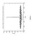
- FIG. 6illustrates an auto-correlation plot of a spread spectrum code.
- FIG. 7illustrates a flow chart representation of the method steps used in an embodiment of this description.
- Each of the reflected signalsoccupies a unique time-delay slot or bin. And by delaying and multiplying the code sequence and multiplying it by the received signal, we can recover the frequency-modulated signal.
- a master or carrier waveis modulated by a single code sequence and delayed by the appropriate time interval specific to a particular signal. All such signals are combined by the action of the fiber optic and the transmitted signal consists of a continuous wave pulse that is multiplied by a single coding sequence and transmitted as a composite optical signal to a receiver where these are collected and photo detected. By filtering the photo detected composite optical signal with the master or reference carrier wave, each individual optical signal is sorted or de-multiplexed into separate electronic signal channels.
- the phase of the de-multiplexed signalcan then be extracted by a frequency modulation (FM) demodulation scheme.
- FMfrequency modulation
- Time-domain reflectometry methodsdo not sample the optical medium fast enough to detect tens or hundreds of kilohertz bandwidth variations in the medium. There is a considerable range of events that occur in a well that produce acoustic perturbations. Multiple fluids and phases (gas bubbles, solids, and some liquid mixtures) may produce recognizable acoustic signatures.
- the extension of reflectometry into much higher frequencies by the use of the spread spectrum technique of this disclosurecan open acoustic monitoring into a realm of new application space—to include an increasing interest in listening for sand flow, high bandwidth telemetry, listening for proppant in hydraulic fracturing operations, measuring fluid flow by acoustic signatures (particularly with active ultrasonic flow monitoring systems), monitoring flow regimes, listening for wellbore leaks (often high frequency), listening for cavitation in flow, listening for plug leaks or inter-zone leaks, monitoring vortex shedding, and wireline sonic logging.
- a fiber optic sensor arrayis typically time-domain multiplexed by the time-of-transversal of an interrogation light wave to each sensor and back to a common optical collection and detection point
- the continuous wave output of a long coherence length phase-stable infrared laseris modulated with pseudo-random binary code sequences.
- Thisis the spread spectrum modulation of a laser using special binary codes.
- These binary code sequencesconsist however of ones and negative ones instead of ones and zeros.
- pseudorandom number sequencesmust respect certain rules, such as length, auto-correlation, cross-correlation, orthogonality, correlation sidelobe behavior, and bits balancing.
- the more popular pseudorandom number sequenceshave names such as Barker, M-Sequence, Gold, Hadamard-Walsh, etc.
- the focusis on auto-correlation.
- the only property of the code currently being usedis the fact that, when the code is multiplied by itself, the result is one when the two versions of the code are time-aligned and a small noise-like signal when they are not time-aligned.
- the auto-correlation function of the codeinforms us of how much time-delay we can impose on the code before the product becomes noise-like. The more impulsive the auto-correlation signal, the smaller the delay we need to have a noise-like signal.
- An example of the power of autocorrelation in providing strong signal-to-noise ratiosis shown in FIG. 6 .
- the correlation function of a signal with itselfis negligible except when the function overlap is perfect or synchronized.
- the correlation function of two different signals of a binary code setresult in a negligible output.
- the presence of other coded signals superimposed on particular coded signaldoes not appreciably or noticeably affect the detection of said code sequence.
- Range determination along the fiberis made possible via the correlation properties of the spread spectrum encoding which uniquely encodes the time-of-flight along the length of the fiber.
- the response at the receive end of the fiberwill be the summation of Rayleigh backscattered signal from the continuum of virtual mirrors along the fiber.
- Each time-shifted signalcan be treated independently since the signal from each virtual mirror will not correlate with each other. This is a key property and advantage of spread spectrum methods.
- Advantages of spread spectruminclude resistance to interference, particularly from signals with different spread spectrum coded signals.
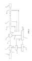
- FIG. 1This is illustrated symbolically in FIG. 1 , which is neither prior art nor the system of this disclosure but a symbolic representation of a return signal R S that is the summation of multiple delayed output returned optical signals R 1 , R 2 , R 3 , R 4 returned from various regions Z 1 , Z 2 , . . . Z n along an extended optical fiber.
- Modulator Mbased on a pseudorandom code provided by code generator G modulates a light source L.
- Each backscattered signal R 1 , R 2 , R 3 , R 4comes from a different position, but arrives back at a detection system D as a net sum binary modulation that can be deconstructed using heterodyne or homodyne demodulation, decoding, and FM demodulation.
- h LP (t)is a low-pass filter that removes the undesired spectral components around 2 ⁇ s .
- ⁇ ⁇0.
- the demodulated baseband signalcan be decoded by:
- h PB (t)is a band pass filter for heterodyne demodulation or a low-pass filter for homodyne demodulation.
- the received signalcan be written as: b ( t,z i ) ⁇ E ss r ( z 1 )[ ⁇ 0 ⁇ h PB ( t ⁇ ) ⁇ A cos( ⁇ ⁇ ⁇ 2 ⁇ s c L ⁇ 1 ⁇ circumflex over (z) ⁇ ( ⁇ , z 1 )) d ⁇ ]dz 1
- the FM signal bandwidthis ⁇ FM
- most of the information of region in 2is spread by the function d(t), and has bandwidth 2( ⁇ c + ⁇ FM ) and is centered around frequency ⁇ ⁇
- most of the information of region in 1is concentrated in frequency, has a bandwidth of ⁇ FM , and is centered around frequency ⁇ ⁇ .
- the decoded signalthen, can be written as: b ( t,z i ) ⁇ z i ⁇ c L ⁇ ⁇ 1 z i +c L ⁇ ⁇ 1 E ss r ( ⁇ A cos( ⁇ ⁇ ⁇ 2 ⁇ sc L ⁇ 1 ⁇ circumflex over (z) ⁇ ( ⁇ , z )) dz+v ( t,z ),
- ⁇ Ais the bandwidth of the modulating signal.
- ⁇ FMusually covers 98% of the energy of the FM signal.
- ⁇ Ais actually the bandwidth of the derivative of p(t, z i ).
- the worst-caselargest possible value of ⁇ A
- a bandwidth for the acoustic pressurecan be arbitrarily chosen and then the assumed FM signal bandwidth can be determined.
- M-Sequencesare bipolar sequences that can be generated through the use of a feedback-shift register (FSR).
- FSRfeedback-shift register
- R c ⁇ ( ⁇ )⁇ 1 - N + 1 NT c ⁇ ⁇ ⁇ ⁇ , ⁇ ⁇ ⁇ ⁇ T c - 1 N , T c ⁇ ⁇ ⁇ ⁇ T b ,
- the symbol period T cis related to the autocorrelation properties of the sequence. Also, it can be seen that the shorter the period the more different two time shifted codes become. Hence, the parameter ⁇ is directly proportional to T c : ⁇ T c ,
- T cThe smaller the T c , the better is the ability of the code to pick out the signal from a desired position.
- the symbol periodis also related to the code bandwidth.
- ⁇ ⁇is the spread in frequency introduced by frequency modulation and ⁇ A is the acoustic signal bandwidth.
- T bNT c > 2 ⁇ L c L ,
- Lis the length of the fiber optic
- T b2 ⁇ ⁇ L c L + ⁇ , where ⁇ is small when compared to
- a fiber optic waveguide 2is positioned into a region of interest, which may be an oil or gas wellbore, oil or gas reservoir, or an extended pipeline. Some possible deployments will be illustrated in a later figure.
- a light source 1is used to generate a continuous primary coherent signal of a pre-determined wavelength that is fed to the fiber optic waveguide.
- a binary code sequence generator 4coupled to a master clock 6 supplies an electronic code c(t) to an optical modulator 3 that receives the primary coherent light signal and modulates it based on the input from the binary code sequence generator.
- the now modulated light signal from modulator 3then enters an optical circulator/coupler 5 that receives the modulated light signal and passes it into the optical fiber span positioned in the region of interest.
- Positions Z 1 , Z 2 , . . . Z n along the deployed optical fiber spanrepresent locations at lengths L 1 , L 2 , . . . L n at which the modulated light signal interacts with the optical fiber and returns backscattered Rayleigh signals.
- the numeral 8represent the terminal end of the deployed optical waveguide.
- the backscattered Rayleigh signalsare directed by the optical circulator/coupler 5 into a detector 7 that performs functions of heterodyne demodulation, decoding, and FM demodulation.
- Detector 7also has photo detectors for detecting and measuring the light signals and a processor for directing all of the functions of demodulation and decoding necessary to produce measured the desired acoustic pressure signals p(t,z) along the length of the deployed optical fiber span.
- FIG. 3A more detailed depiction of the detector system 7 , to explain the separate functions of heterodyne or homodyne demodulation, decoding, and FM demodulation is shown in FIG. 3 .
- the optical signalis heterodyne demodulated by combining the optical signal E b (t) with another optical signal cos(( ⁇ s + ⁇ ⁇ ) t that is shifted in frequency by ⁇ s + ⁇ ⁇ relative to the received signal.
- ⁇ ⁇0.
- the output of demodulator 201now an electronic signal, is submitted to decoder 202 , which extracts the information of the positions Z 1 , Z 2 , . . .
- the phase of each of the signalsare then extracted by the FM Demodulator and the acoustic pressure signal p(t,z 1 ) . . . p(t,z n ) associated with each position along the fiber is obtained.
- the elements of the detector systemwould be photo detectors and a processor for controlling all of the functions and computations of the detector system and providing the output of acoustic pressure signals.
- FIG. 4exhibits more details regarding decoder 202 of FIG. 3 .
- the decoderprovides circuitry for separating the electronic signal b(t) from the heterodyne demodulator into separate branches representing the positions Z 1 , Z 2 , . . . , Z n along the sensing fiber optic.
- the binary coding sequence c(t)is also split into several signals, each signal being time delayed with a delay proportional to the time it takes for the code to arrive at a defined position of the fiber.
- the circuitry for providing this functionalitycould be provided either analogically or digitally.
- the electronic signal and the delayed coding sequencesare then multiplied in time and band-pass filtered (low-pass filtered in the case of homodyne demodulation) to obtain a signal that only contains the information of a certain position of the optical fiber.
- Configuration 27is a fairly typical retrievable wireline in which a fiber optic cable 33 is deployed within metal tubing 34 and down to a bottom hole gauge or termination 36 .
- the metal tubing 34is surrounded by production casing 32 , which is surrounded by a surface casing 31 near the surface.
- Configuration 28represents a permanent tubing installation in which a fiber optic cable 33 is attached to metal tubing 34 .
- configuration 29represents a casing attachment in which the fiber optic cable 33 is attached outside the production casing 32 .
- there are other possible configurations (not shown) when using distributed sensing systems in applicationssuch as perimeter security systems, monitoring of subsea umbilical's, risers, or pipelines.
- FIG. 7spells out the preferred code requirements for the Maximal Length Sequences (M-Sequences) proposed in this disclosure along with the use of auto-correlation.
- the practitionerspecifies the fiber optic length, the desired spatial sampling, and the acoustic bandwidth.
- Tbis chosen so that it is very close to
Landscapes
- Physics & Mathematics (AREA)
- General Physics & Mathematics (AREA)
- Engineering & Computer Science (AREA)
- Life Sciences & Earth Sciences (AREA)
- Remote Sensing (AREA)
- Biochemistry (AREA)
- Health & Medical Sciences (AREA)
- General Health & Medical Sciences (AREA)
- Chemical & Material Sciences (AREA)
- Immunology (AREA)
- Pathology (AREA)
- Analytical Chemistry (AREA)
- Geology (AREA)
- Mining & Mineral Resources (AREA)
- Optics & Photonics (AREA)
- Acoustics & Sound (AREA)
- Electromagnetism (AREA)
- Geophysics (AREA)
- Environmental & Geological Engineering (AREA)
- Fluid Mechanics (AREA)
- General Life Sciences & Earth Sciences (AREA)
- Geochemistry & Mineralogy (AREA)
- Measurement Of Mechanical Vibrations Or Ultrasonic Waves (AREA)
- Investigating Or Analysing Materials By Optical Means (AREA)
Abstract
Description
- 1) Gold
- 2) Kasami
- 3) Golay
- 4) Hadamard-Walsh
- 5) M-Sequences (binary maximal-length linear feedback shift register sequences)
Ei(t)=c(t)cos(ωst),
Eb(t)=∫0zr(z)μAc(t−2cL−1{circumflex over (z)}(t,z))Esscos(ωs(t−2cL−1{circumflex over (z)}(t,z)))dz,
{circumflex over (z)}(t,z)=z+μL∫0zp(t,x)dx,
c(τ−2cL−1{circumflex over (z)}(τ,z))=c(τ−2cL−1(z+μL∫0zp(t,x)dx))≈c(τ−2cL−1z),


- The larger the bandwidth of σcrelative to σFM, the easier it is to remove the interference from other spatial regions of the fiber.
- The smaller the value of ε, the better the tuning of the spatial information, thus allowing more spatial points to be sampled.
- On the other hand, the value of E cannot be so small as to make the approximation that the time delay variation caused by the acoustic pressure is negligible compared to the time delay caused by the time of flight of the optic wave invalid.
- The higher the beat frequency Δω, the more selective the filter hPBmust be.
- The center frequency should be high enough so that it is possible to retrieve the acoustic pressure signal.
sFM(t)=Accos(ωct+fΔΨ(t)),
σFM=2(fΔ+σA),
- Its auto-correlation is
- where Tb=NTc.
- The product of two time-aligned codes is c2(t)=1.
- Its power spectral density is
- and the spectrum is discrete-valued and has an envelope that follows that of a sinc2(•) function. Using this information it is possible to approximate the signal bandwidth. Hence, the bandwidth of σccan be approximated as 2/Tc.
ε∝Tc,
σc=2/Tc>>2(σΔ+σA),
- 1. Specify the fiber optic cable length L, the desired spatial sampling Δz, and acoustic signal bandwidth σA.
- 2. Choose Tbso that
where ρ is small when compared to
- 3. Choose N so that NTc=Tband Tcso that
Then in step430 N is chosen so that NTc=Tband Tcso that
Claims (22)
Priority Applications (1)
| Application Number | Priority Date | Filing Date | Title |
|---|---|---|---|
| US16/542,187USRE49680E1 (en) | 2013-08-12 | 2013-08-12 | Systems and methods for spread spectrum distributed acoustic sensor monitoring |
Applications Claiming Priority (1)
| Application Number | Priority Date | Filing Date | Title |
|---|---|---|---|
| PCT/US2013/054588WO2015023255A1 (en) | 2013-08-12 | 2013-08-12 | Systems and methods for spread spectrum distributed acoustic sensor monitoring |
Related Child Applications (1)
| Application Number | Title | Priority Date | Filing Date |
|---|---|---|---|
| US16542187Reissue | 2019-08-15 |
Publications (2)
| Publication Number | Publication Date |
|---|---|
| US20160146662A1 US20160146662A1 (en) | 2016-05-26 |
| US9733120B2true US9733120B2 (en) | 2017-08-15 |
Family
ID=52468525
Family Applications (2)
| Application Number | Title | Priority Date | Filing Date |
|---|---|---|---|
| US14/903,503CeasedUS9733120B2 (en) | 2013-08-12 | 2013-08-12 | Systems and methods for spread spectrum distributed acoustic sensor monitoring |
| US16/542,187Active2033-12-03USRE49680E1 (en) | 2013-08-12 | 2013-08-12 | Systems and methods for spread spectrum distributed acoustic sensor monitoring |
Family Applications After (1)
| Application Number | Title | Priority Date | Filing Date |
|---|---|---|---|
| US16/542,187Active2033-12-03USRE49680E1 (en) | 2013-08-12 | 2013-08-12 | Systems and methods for spread spectrum distributed acoustic sensor monitoring |
Country Status (2)
| Country | Link |
|---|---|
| US (2) | US9733120B2 (en) |
| WO (1) | WO2015023255A1 (en) |
Cited By (17)
| Publication number | Priority date | Publication date | Assignee | Title |
|---|---|---|---|---|
| US20160320232A1 (en)* | 2014-01-21 | 2016-11-03 | Halliburton Energy Services, Inc. | Systems and Methods for Multiple-Code Continuous-Wave Distributed Accoustic Sensing |
| US20160377528A1 (en)* | 2013-12-02 | 2016-12-29 | Commissariat A L'energie Atomique Et Aux Energies Alternatives | Testing of an industrial structure |
| US10975687B2 (en) | 2017-03-31 | 2021-04-13 | Bp Exploration Operating Company Limited | Well and overburden monitoring using distributed acoustic sensors |
| US11053791B2 (en) | 2016-04-07 | 2021-07-06 | Bp Exploration Operating Company Limited | Detecting downhole sand ingress locations |
| US11098576B2 (en) | 2019-10-17 | 2021-08-24 | Lytt Limited | Inflow detection using DTS features |
| US11162353B2 (en) | 2019-11-15 | 2021-11-02 | Lytt Limited | Systems and methods for draw down improvements across wellbores |
| US11199085B2 (en) | 2017-08-23 | 2021-12-14 | Bp Exploration Operating Company Limited | Detecting downhole sand ingress locations |
| US11199084B2 (en) | 2016-04-07 | 2021-12-14 | Bp Exploration Operating Company Limited | Detecting downhole events using acoustic frequency domain features |
| US11333573B2 (en) | 2014-08-28 | 2022-05-17 | Adelos, Inc. | Noise management for optical time delay interferometry |
| US11333636B2 (en) | 2017-10-11 | 2022-05-17 | Bp Exploration Operating Company Limited | Detecting events using acoustic frequency domain features |
| US11466563B2 (en) | 2020-06-11 | 2022-10-11 | Lytt Limited | Systems and methods for subterranean fluid flow characterization |
| US11473424B2 (en) | 2019-10-17 | 2022-10-18 | Lytt Limited | Fluid inflow characterization using hybrid DAS/DTS measurements |
| US11593683B2 (en) | 2020-06-18 | 2023-02-28 | Lytt Limited | Event model training using in situ data |
| US11643923B2 (en) | 2018-12-13 | 2023-05-09 | Bp Exploration Operating Company Limited | Distributed acoustic sensing autocalibration |
| USRE49680E1 (en) | 2013-08-12 | 2023-10-03 | Adelos, Llc | Systems and methods for spread spectrum distributed acoustic sensor monitoring |
| US11859488B2 (en) | 2018-11-29 | 2024-01-02 | Bp Exploration Operating Company Limited | DAS data processing to identify fluid inflow locations and fluid type |
| US12196074B2 (en) | 2019-09-20 | 2025-01-14 | Lytt Limited | Systems and methods for sand ingress prediction for subterranean wellbores |
Families Citing this family (19)
| Publication number | Priority date | Publication date | Assignee | Title |
|---|---|---|---|---|
| NZ753554A (en)* | 2016-11-08 | 2020-05-29 | Baker Hughes A Ge Co Llc | Dual telemetric coiled tubing system |
| US10330526B1 (en) | 2017-12-06 | 2019-06-25 | Saudi Arabian Oil Company | Determining structural tomographic properties of a geologic formation |
| GB2578116A (en) | 2018-10-16 | 2020-04-22 | Aiq Dienstleistungen Ug Haftungsbeschraenkt | High rate distributed acoustic sensing using high power light pulses |
| CN109538197B (en)* | 2018-11-01 | 2020-06-05 | 中国石油大学(北京) | Method and device for determining drilling track of oil and gas reservoir and storage medium |
| US11319803B2 (en) | 2019-04-23 | 2022-05-03 | Baker Hughes Holdings Llc | Coiled tubing enabled dual telemetry system |
| FR3097337B1 (en)* | 2019-06-13 | 2021-07-23 | Commissariat Energie Atomique | Acousto-optical imaging system |
| US11835675B2 (en) | 2019-08-07 | 2023-12-05 | Saudi Arabian Oil Company | Determination of geologic permeability correlative with magnetic permeability measured in-situ |
| CN111289088B (en)* | 2020-03-20 | 2024-12-13 | 电子科技大学 | A multi-channel telemetry optical fiber sensing system and method |
| FR3116898A1 (en)* | 2020-11-30 | 2022-06-03 | Saipem S.A. | Method and system for the temporal determination of a phase interface level of a multiphase fluid present in a vertical pipe |
| US11840919B2 (en) | 2021-01-04 | 2023-12-12 | Saudi Arabian Oil Company | Photoacoustic nanotracers |
| CN113125559B (en)* | 2021-04-16 | 2022-07-26 | 山东正元地球物理信息技术有限公司 | Method for identifying pipeline position based on micro-motion information |
| US11879328B2 (en) | 2021-08-05 | 2024-01-23 | Saudi Arabian Oil Company | Semi-permanent downhole sensor tool |
| AU2022373462B2 (en)* | 2021-10-20 | 2025-04-03 | X Development Llc | Detecting seismic events using multispan signals |
| US12253467B2 (en) | 2021-12-13 | 2025-03-18 | Saudi Arabian Oil Company | Determining partition coefficients of tracer analytes |
| US11860077B2 (en) | 2021-12-14 | 2024-01-02 | Saudi Arabian Oil Company | Fluid flow sensor using driver and reference electromechanical resonators |
| US12000278B2 (en) | 2021-12-16 | 2024-06-04 | Saudi Arabian Oil Company | Determining oil and water production rates in multiple production zones from a single production well |
| US11867049B1 (en) | 2022-07-19 | 2024-01-09 | Saudi Arabian Oil Company | Downhole logging tool |
| US11913329B1 (en) | 2022-09-21 | 2024-02-27 | Saudi Arabian Oil Company | Untethered logging devices and related methods of logging a wellbore |
| CN119197740B (en)* | 2024-11-25 | 2025-03-07 | 浙江亨特科技有限公司 | A monitoring and early warning method and system for distributed optical fiber acoustic wave sensors |
Citations (21)
| Publication number | Priority date | Publication date | Assignee | Title |
|---|---|---|---|---|
| US5000568A (en) | 1986-11-26 | 1991-03-19 | Hewlett-Packard Company | Spread spectrum optical time domain reflectometer |
| US5194847A (en) | 1991-07-29 | 1993-03-16 | Texas A & M University System | Apparatus and method for fiber optic intrusion sensing |
| US5353627A (en) | 1993-08-19 | 1994-10-11 | Texaco Inc. | Passive acoustic detection of flow regime in a multi-phase fluid flow |
| US5635829A (en) | 1994-08-12 | 1997-06-03 | Matsushita Electric Industrial Co., Ltd. | Optical sensor |
| US5686986A (en) | 1995-09-26 | 1997-11-11 | Ando Electric Co., Ltd. | Optical fiber characteristic measuring device |
| US5696863A (en)* | 1982-08-06 | 1997-12-09 | Kleinerman; Marcos Y. | Distributed fiber optic temperature sensors and systems |
| US5991479A (en)* | 1984-05-14 | 1999-11-23 | Kleinerman; Marcos Y. | Distributed fiber optic sensors and systems |
| US6173091B1 (en) | 1997-11-17 | 2001-01-09 | Northrop Grumman Corporation | Fiber optic Fabry-Perot sensor for measuring absolute strain |
| US6285806B1 (en) | 1998-05-31 | 2001-09-04 | The United States Of America As Represented By The Secretary Of The Navy | Coherent reflectometric fiber Bragg grating sensor array |
| US20060028636A1 (en) | 2004-08-06 | 2006-02-09 | Payton Robert M | Natural fiber span reflectometer providing a virtual phase signal sensing array capability |
| US20060066839A1 (en) | 2004-08-06 | 2006-03-30 | Payton Robert M | Natural fiber span reflectometer providing a virtual signal sensing array capability |
| US7268863B2 (en) | 2004-08-06 | 2007-09-11 | The United States Of America As Represented By The Secretary Of The Navy | Natural fiber span reflectometer providing a spread spectrum virtual sensing array capability |
| US7274441B2 (en) | 2004-08-06 | 2007-09-25 | The United States Of America Represented By The Secretary Of The Navy | Natural fiber span reflectometer providing a virtual differential signal sensing array capability |
| US20090252491A1 (en)* | 2006-02-24 | 2009-10-08 | Peter Healey | Sensing a disturbance |
| US7946341B2 (en) | 2007-11-02 | 2011-05-24 | Schlumberger Technology Corporation | Systems and methods for distributed interferometric acoustic monitoring |
| US20110228255A1 (en)* | 2008-11-27 | 2011-09-22 | Neubrex Co., Ltd | Distributed optical fiber sensor |
| JP2013079906A (en) | 2011-10-05 | 2013-05-02 | Neubrex Co Ltd | Distribution type optical fiber acoustic wave detection device |
| KR20130081062A (en) | 2012-01-06 | 2013-07-16 | (주)파이버프로 | Apparatus for fiber optic perturbation sensing and method of the same |
| JP2013181789A (en) | 2012-02-29 | 2013-09-12 | Oki Electric Ind Co Ltd | Interference type optical fiber sensor |
| US20150211983A1 (en)* | 2014-01-28 | 2015-07-30 | Schlumberger Technology Corporation | Fluid analysis by optical spectroscopy with photoacoustic detection |
| US20160320232A1 (en)* | 2014-01-21 | 2016-11-03 | Halliburton Energy Services, Inc. | Systems and Methods for Multiple-Code Continuous-Wave Distributed Accoustic Sensing |
Family Cites Families (79)
| Publication number | Priority date | Publication date | Assignee | Title |
|---|---|---|---|---|
| US4238856A (en) | 1979-01-24 | 1980-12-09 | The United States Of America As Represented By The Secretary Of The Navy | Fiber-optic acoustic sensor |
| GB2190186B (en) | 1986-05-09 | 1990-12-19 | Dr Jeremy Kenneth Arth Everard | Greatly enhanced spatial detection of optical backscatter for sensor applications |
| GB2193610A (en) | 1986-08-05 | 1988-02-10 | Stc Plc | Coherent mixing of optical signals |
| US4817101A (en) | 1986-09-26 | 1989-03-28 | The United States Of America As Represented By The United States Department Of Energy | Heterodyne laser spectroscopy system |
| US4775216A (en) | 1987-02-02 | 1988-10-04 | Litton Systems, Inc. | Fiber optic sensor array and method |
| US4889986A (en) | 1988-08-18 | 1989-12-26 | The United States Of America As Represented By The Secretary Of The Navy | Serial interferometric fiber-optic sensor array |
| DE68907886T2 (en) | 1989-01-24 | 1994-01-13 | Hewlett Packard Gmbh | Method and device for using optical time domain reflectometers. |
| US5146359A (en) | 1989-01-26 | 1992-09-08 | The Furukawa Electric Co., Ltd. | Double-stage phase-diversity receiver |
| US5115332A (en) | 1989-07-20 | 1992-05-19 | Fujitsu Limited | Receiver for coherent optical communication |
| US5177764A (en) | 1989-12-28 | 1993-01-05 | Harmonic Lightwaves, Inc. | Unidirectional, planar ring laser with birefringence |
| US5212825A (en) | 1990-11-09 | 1993-05-18 | Litton Systems, Inc. | Synthetic heterodyne demodulator circuit |
| US5956355A (en) | 1991-04-29 | 1999-09-21 | Massachusetts Institute Of Technology | Method and apparatus for performing optical measurements using a rapidly frequency-tuned laser |
| US5371588A (en) | 1993-11-10 | 1994-12-06 | University Of Maryland, College Park | Surface profile and material mapper using a driver to displace the sample in X-Y-Z directions |
| GB9324333D0 (en) | 1993-11-26 | 1994-01-12 | Sensor Dynamics Ltd | Measurement of one or more physical parameters |
| US6008487A (en) | 1995-02-02 | 1999-12-28 | Yokogawa Electric Corporation | Optical-fiber inspection device |
| US5844235A (en) | 1995-02-02 | 1998-12-01 | Yokogawa Electric Corporation | Optical frequency domain reflectometer for use as an optical fiber testing device |
| US5633741A (en) | 1995-02-23 | 1997-05-27 | Lucent Technologies Inc. | Multichannel optical fiber communications |
| US6216540B1 (en) | 1995-06-06 | 2001-04-17 | Robert S. Nelson | High resolution device and method for imaging concealed objects within an obscuring medium |
| US5694408A (en) | 1995-06-07 | 1997-12-02 | Mcdonnell Douglas Corporation | Fiber optic laser system and associated lasing method |
| WO1997046870A1 (en) | 1996-06-06 | 1997-12-11 | Gn Nettest (New York) | Retroflectively reducing coherence noise in reflectometers |
| DE69631475T2 (en) | 1996-07-16 | 2005-01-13 | Perkin-Elmer Ltd., Beaconsfield | Control of a microscope screen |
| US6111816A (en) | 1997-02-03 | 2000-08-29 | Teratech Corporation | Multi-dimensional beamforming device |
| US5847816A (en) | 1997-01-14 | 1998-12-08 | Mcdonnell Douglas Corporation | Fiber optic micro-doppler ladar system and operating method therefor |
| US5847817A (en) | 1997-01-14 | 1998-12-08 | Mcdonnell Douglas Corporation | Method for extending range and sensitivity of a fiber optic micro-doppler ladar system and apparatus therefor |
| US6043921A (en) | 1997-08-12 | 2000-03-28 | The United States Of America As Represented By The Secretary Of The Navy | Fading-free optical phase rate receiver |
| US6034760A (en) | 1997-10-21 | 2000-03-07 | Flight Safety Technologies, Inc. | Method of detecting weather conditions in the atmosphere |
| DE19807891A1 (en) | 1998-02-25 | 1999-08-26 | Abb Research Ltd | Fiber-laser sensor for measurement of elongation, temperature or especially isotropic pressure in oil well |
| US6127948A (en) | 1998-06-17 | 2000-10-03 | Gurley Precision Instruments, Inc. | Bidirectional synthesis of pseudorandom sequences for arbitrary encoding resolutions |
| DE69929627T2 (en) | 1998-11-02 | 2006-09-14 | Airbiquity Inc., Bainbridge Island | GEO-ROOM ADDRESSING TO THE INTERNET PROTOCOL |
| DE19860410A1 (en) | 1998-12-28 | 2000-06-29 | Abb Research Ltd | Fiber laser sensor for measuring differential pressures and flow velocities |
| CA2271918A1 (en) | 1999-05-11 | 2000-11-11 | Lee A. Danisch | Transversely coupled fiber optic sensor for measuring and classifying contact and shape |
| US6626043B1 (en) | 2000-01-31 | 2003-09-30 | Weatherford/Lamb, Inc. | Fluid diffusion resistant glass-encased fiber optic sensor |
| JP2001356070A (en) | 2000-06-13 | 2001-12-26 | Ando Electric Co Ltd | Optical fiber strain measurement device |
| GB2372100B (en) | 2001-02-13 | 2003-04-16 | Marconi Caswell Ltd | Optical Waveguide Bragg Grating System |
| JP4048729B2 (en) | 2001-04-24 | 2008-02-20 | 横河電機株式会社 | Optical fiber characteristic measuring device |
| US6571034B2 (en) | 2001-06-28 | 2003-05-27 | Corning Incorporated | Spectrally-shaped optical components using a wavelength-dispersive element and a reflective array |
| US20080301298A1 (en) | 2002-07-29 | 2008-12-04 | Linda Bernardi | Identifying a computing device |
| CA2498924A1 (en) | 2002-10-04 | 2004-04-22 | Sabeus Photonics, Inc. | Rugged fiber optic array |
| AU2002344444A1 (en) | 2002-11-01 | 2004-05-25 | Kinzo Kishida | Distributed optical fiber sensor system |
| US7460793B2 (en) | 2002-12-11 | 2008-12-02 | Michael George Taylor | Coherent optical detection and signal processing method and system |
| US7576648B2 (en) | 2003-08-01 | 2009-08-18 | Senstar-Stellar Corporation | Cable guided intrusion detection sensor, system and method |
| US7488929B2 (en) | 2003-08-13 | 2009-02-10 | Zygo Corporation | Perimeter detection using fiber optic sensors |
| CN100346669C (en) | 2003-09-18 | 2007-10-31 | 复旦大学 | Non-microphone voice transmission device |
| US20050149264A1 (en) | 2003-12-30 | 2005-07-07 | Schlumberger Technology Corporation | System and Method to Interpret Distributed Temperature Sensor Data and to Determine a Flow Rate in a Well |
| US7142736B2 (en) | 2004-01-05 | 2006-11-28 | Optellios, Inc. | Distributed fiber sensor with interference detection and polarization state management |
| US20050174563A1 (en) | 2004-02-11 | 2005-08-11 | Evans Alan F. | Active fiber loss monitor and method |
| GB0409865D0 (en) | 2004-05-01 | 2004-06-09 | Sensornet Ltd | Direct measurement of brillouin frequency in distributed optical sensing systems |
| US7030975B2 (en) | 2004-05-13 | 2006-04-18 | The Boeing Company | Mixer-based in-service time domain reflectometer apparatus and methods |
| US7667830B2 (en) | 2004-05-13 | 2010-02-23 | The Boeing Company | Mixer-based time domain reflectometer and method |
| US7187816B2 (en) | 2004-12-13 | 2007-03-06 | Purdue Research Foundation | In-fiber whitelight interferometry using long-period fiber grating |
| EP1712888A1 (en) | 2005-04-11 | 2006-10-18 | Agilent Technologies Inc | Time-of-flight measurement using pulse sequences |
| EP1746403A1 (en) | 2005-07-19 | 2007-01-24 | Agilent Technologies, Inc. | Optical reflectometry analysis with a time-adjustment of partial responses |
| US20090222541A1 (en) | 2005-11-08 | 2009-09-03 | Nortel Networks Limited | Dynamic sensor network registry |
| US8024974B2 (en) | 2005-11-23 | 2011-09-27 | 3M Innovative Properties Company | Cantilevered bioacoustic sensor and method using same |
| US7548071B2 (en) | 2006-01-31 | 2009-06-16 | University Of Utah Research Foundation | Reflectometry test system using a sliding pseudo-noise reference |
| EP1881338B1 (en) | 2006-07-20 | 2011-09-07 | Semiconductor Energy Laboratory Co., Ltd. | Position information detection system and position information detection method |
| GB2440952B (en) | 2006-08-16 | 2009-04-08 | Schlumberger Holdings | Measuring brillouin backscatter from an optical fibre using digitisation |
| GB2442486B (en) | 2006-10-06 | 2009-01-07 | Schlumberger Holdings | Measuring brillouin backscatter from an optical fibre using a tracking signal |
| GB2442745B (en) | 2006-10-13 | 2011-04-06 | At & T Corp | Method and apparatus for acoustic sensing using multiple optical pulses |
| US8045143B2 (en) | 2006-10-23 | 2011-10-25 | The Boeing Company | Optical phase domain reflectometer |
| WO2008063598A2 (en) | 2006-11-17 | 2008-05-29 | Honda Motor Co., Ltd. | Fully bayesian linear regression |
| JP5122120B2 (en) | 2006-12-13 | 2013-01-16 | 横河電機株式会社 | Optical fiber characteristic measuring device |
| ES2326152B1 (en) | 2006-12-29 | 2010-06-29 | Universitat Politecnica De Catalunya (Upc) | HOMODINE RECEIVER FOR OPTICAL COMMUNICATIONS WITH PROCESSING AFTER. |
| US7339721B1 (en) | 2007-02-28 | 2008-03-04 | Corning Incorporated | Optical fiber light source based on third-harmonic generation |
| DE102007046507B4 (en) | 2007-09-28 | 2024-10-31 | Carl Zeiss Meditec Ag | short-coherence interferometer |
| CN101226100B (en) | 2008-01-31 | 2010-08-25 | 太原理工大学 | Chaos light time domain reflectometer and measuring method thereof |
| US7646944B2 (en) | 2008-05-16 | 2010-01-12 | Celight, Inc. | Optical sensor with distributed sensitivity |
| EP2361393B1 (en) | 2008-11-06 | 2020-12-23 | Services Petroliers Schlumberger | Distributed acoustic wave detection |
| US8417490B1 (en) | 2009-05-11 | 2013-04-09 | Eagle Harbor Holdings, Llc | System and method for the configuration of an automotive vehicle with modeled sensors |
| CN201829006U (en) | 2010-08-04 | 2011-05-11 | 武汉安通科技产业发展有限公司 | Optical fiber sensing intelligent addressing perimeter intrusion alarm system |
| EP2596387B1 (en) | 2010-09-01 | 2021-10-06 | Services Pétroliers Schlumberger | Distributed fiber optic sensor system with improved linearity |
| TW201315170A (en) | 2011-09-27 | 2013-04-01 | Chunghwa Telecom Co Ltd | Light frequency domain reflective optical network test method |
| US20130229649A1 (en) | 2012-03-01 | 2013-09-05 | Ming-Jun Li | Optical brillouin sensing systems |
| TWM439805U (en) | 2012-05-29 | 2012-10-21 | Zealtek Electronic Co Ltd | Composite fiber events inspection and test device |
| US10031246B2 (en) | 2012-11-15 | 2018-07-24 | The United States Of America As Represented By The Secretary Of The Army | RF-photonic system for acoustic and/or vibrational sensing using optical fiber and method thereof |
| US9581489B2 (en) | 2013-01-26 | 2017-02-28 | Halliburton Energy Services, Inc. | Distributed acoustic sensing with multimode fiber |
| FI125558B (en) | 2013-05-29 | 2015-11-30 | Iprotoxi Oy | Device for controlling sensors |
| US9733120B2 (en) | 2013-08-12 | 2017-08-15 | Halliburton Energy Services, Inc. | Systems and methods for spread spectrum distributed acoustic sensor monitoring |
| WO2016033199A1 (en) | 2014-08-28 | 2016-03-03 | Adelos, Inc. | Real-time fiber optic interferometry controller |
- 2013
- 2013-08-12USUS14/903,503patent/US9733120B2/ennot_activeCeased
- 2013-08-12WOPCT/US2013/054588patent/WO2015023255A1/enactiveApplication Filing
- 2013-08-12USUS16/542,187patent/USRE49680E1/enactiveActive
Patent Citations (22)
| Publication number | Priority date | Publication date | Assignee | Title |
|---|---|---|---|---|
| US5696863A (en)* | 1982-08-06 | 1997-12-09 | Kleinerman; Marcos Y. | Distributed fiber optic temperature sensors and systems |
| US5991479A (en)* | 1984-05-14 | 1999-11-23 | Kleinerman; Marcos Y. | Distributed fiber optic sensors and systems |
| US5000568A (en) | 1986-11-26 | 1991-03-19 | Hewlett-Packard Company | Spread spectrum optical time domain reflectometer |
| US5194847A (en) | 1991-07-29 | 1993-03-16 | Texas A & M University System | Apparatus and method for fiber optic intrusion sensing |
| US5353627A (en) | 1993-08-19 | 1994-10-11 | Texaco Inc. | Passive acoustic detection of flow regime in a multi-phase fluid flow |
| US5635829A (en) | 1994-08-12 | 1997-06-03 | Matsushita Electric Industrial Co., Ltd. | Optical sensor |
| US5686986A (en) | 1995-09-26 | 1997-11-11 | Ando Electric Co., Ltd. | Optical fiber characteristic measuring device |
| US6173091B1 (en) | 1997-11-17 | 2001-01-09 | Northrop Grumman Corporation | Fiber optic Fabry-Perot sensor for measuring absolute strain |
| US6285806B1 (en) | 1998-05-31 | 2001-09-04 | The United States Of America As Represented By The Secretary Of The Navy | Coherent reflectometric fiber Bragg grating sensor array |
| US20060066839A1 (en) | 2004-08-06 | 2006-03-30 | Payton Robert M | Natural fiber span reflectometer providing a virtual signal sensing array capability |
| US20060028636A1 (en) | 2004-08-06 | 2006-02-09 | Payton Robert M | Natural fiber span reflectometer providing a virtual phase signal sensing array capability |
| US7030971B1 (en) | 2004-08-06 | 2006-04-18 | The United States Of America Represented By The Secretary Of The Navy | Natural fiber span reflectometer providing a virtual signal sensing array capability |
| US7268863B2 (en) | 2004-08-06 | 2007-09-11 | The United States Of America As Represented By The Secretary Of The Navy | Natural fiber span reflectometer providing a spread spectrum virtual sensing array capability |
| US7274441B2 (en) | 2004-08-06 | 2007-09-25 | The United States Of America Represented By The Secretary Of The Navy | Natural fiber span reflectometer providing a virtual differential signal sensing array capability |
| US20090252491A1 (en)* | 2006-02-24 | 2009-10-08 | Peter Healey | Sensing a disturbance |
| US7946341B2 (en) | 2007-11-02 | 2011-05-24 | Schlumberger Technology Corporation | Systems and methods for distributed interferometric acoustic monitoring |
| US20110228255A1 (en)* | 2008-11-27 | 2011-09-22 | Neubrex Co., Ltd | Distributed optical fiber sensor |
| JP2013079906A (en) | 2011-10-05 | 2013-05-02 | Neubrex Co Ltd | Distribution type optical fiber acoustic wave detection device |
| KR20130081062A (en) | 2012-01-06 | 2013-07-16 | (주)파이버프로 | Apparatus for fiber optic perturbation sensing and method of the same |
| JP2013181789A (en) | 2012-02-29 | 2013-09-12 | Oki Electric Ind Co Ltd | Interference type optical fiber sensor |
| US20160320232A1 (en)* | 2014-01-21 | 2016-11-03 | Halliburton Energy Services, Inc. | Systems and Methods for Multiple-Code Continuous-Wave Distributed Accoustic Sensing |
| US20150211983A1 (en)* | 2014-01-28 | 2015-07-30 | Schlumberger Technology Corporation | Fluid analysis by optical spectroscopy with photoacoustic detection |
Cited By (21)
| Publication number | Priority date | Publication date | Assignee | Title |
|---|---|---|---|---|
| USRE49680E1 (en) | 2013-08-12 | 2023-10-03 | Adelos, Llc | Systems and methods for spread spectrum distributed acoustic sensor monitoring |
| US20160377528A1 (en)* | 2013-12-02 | 2016-12-29 | Commissariat A L'energie Atomique Et Aux Energies Alternatives | Testing of an industrial structure |
| US10324026B2 (en)* | 2013-12-02 | 2019-06-18 | Commissariat A L'energie Atomique Et Aux Energies Alternatives | Testing of an industrial structure |
| US20160320232A1 (en)* | 2014-01-21 | 2016-11-03 | Halliburton Energy Services, Inc. | Systems and Methods for Multiple-Code Continuous-Wave Distributed Accoustic Sensing |
| US10139268B2 (en)* | 2014-01-21 | 2018-11-27 | Halliburton Energy Services, Inc. | Systems and methods for multiple-code continuous-wave distributed acoustic sensing |
| US11333573B2 (en) | 2014-08-28 | 2022-05-17 | Adelos, Inc. | Noise management for optical time delay interferometry |
| US11215049B2 (en) | 2016-04-07 | 2022-01-04 | Bp Exploration Operating Company Limited | Detecting downhole events using acoustic frequency domain features |
| US11199084B2 (en) | 2016-04-07 | 2021-12-14 | Bp Exploration Operating Company Limited | Detecting downhole events using acoustic frequency domain features |
| US11053791B2 (en) | 2016-04-07 | 2021-07-06 | Bp Exploration Operating Company Limited | Detecting downhole sand ingress locations |
| US11530606B2 (en) | 2016-04-07 | 2022-12-20 | Bp Exploration Operating Company Limited | Detecting downhole sand ingress locations |
| US10975687B2 (en) | 2017-03-31 | 2021-04-13 | Bp Exploration Operating Company Limited | Well and overburden monitoring using distributed acoustic sensors |
| US11199085B2 (en) | 2017-08-23 | 2021-12-14 | Bp Exploration Operating Company Limited | Detecting downhole sand ingress locations |
| US11333636B2 (en) | 2017-10-11 | 2022-05-17 | Bp Exploration Operating Company Limited | Detecting events using acoustic frequency domain features |
| US11859488B2 (en) | 2018-11-29 | 2024-01-02 | Bp Exploration Operating Company Limited | DAS data processing to identify fluid inflow locations and fluid type |
| US11643923B2 (en) | 2018-12-13 | 2023-05-09 | Bp Exploration Operating Company Limited | Distributed acoustic sensing autocalibration |
| US12196074B2 (en) | 2019-09-20 | 2025-01-14 | Lytt Limited | Systems and methods for sand ingress prediction for subterranean wellbores |
| US11098576B2 (en) | 2019-10-17 | 2021-08-24 | Lytt Limited | Inflow detection using DTS features |
| US11473424B2 (en) | 2019-10-17 | 2022-10-18 | Lytt Limited | Fluid inflow characterization using hybrid DAS/DTS measurements |
| US11162353B2 (en) | 2019-11-15 | 2021-11-02 | Lytt Limited | Systems and methods for draw down improvements across wellbores |
| US11466563B2 (en) | 2020-06-11 | 2022-10-11 | Lytt Limited | Systems and methods for subterranean fluid flow characterization |
| US11593683B2 (en) | 2020-06-18 | 2023-02-28 | Lytt Limited | Event model training using in situ data |
Also Published As
| Publication number | Publication date |
|---|---|
| USRE49680E1 (en) | 2023-10-03 |
| WO2015023255A1 (en) | 2015-02-19 |
| US20160146662A1 (en) | 2016-05-26 |
Similar Documents
| Publication | Publication Date | Title |
|---|---|---|
| US9733120B2 (en) | Systems and methods for spread spectrum distributed acoustic sensor monitoring | |
| US10139268B2 (en) | Systems and methods for multiple-code continuous-wave distributed acoustic sensing | |
| EP3662308B1 (en) | Simultaneous distributed measurement monitoring over multiple fibers | |
| US11333573B2 (en) | Noise management for optical time delay interferometry | |
| US10120104B2 (en) | Downhole surveillance | |
| CA3064870C (en) | Angular response compensation for das vsp | |
| CA2924957C (en) | Fiber optic distributed acoustic measurements via fmcw interrogation | |
| US20120237205A1 (en) | System and method to compensate for arbitrary optical fiber lead-ins in an optical frequency domain reflectometry system | |
| CA2999465A1 (en) | Fiber optic distributed acoustic sensor omnidirectional antenna for use in downhole and marine applications | |
| CN107923846A (en) | Optical fiber senses | |
| US20220283330A1 (en) | Gauge Length Correction For Seismic Attenuation From Distributed Acoustic System Fiber Optic Data | |
| NO20170436A1 (en) | Well Monitoring with Optical Electromagnetic Sensing System | |
| US10018749B2 (en) | Distributed optical sensors for acoustic and vibration monitoring | |
| US11675099B2 (en) | De-spiking distributed acoustic sensor seismic profile | |
| Liu et al. | The Applications of Interferometric Fiber-Optic Sensors in Oilfield |
Legal Events
| Date | Code | Title | Description |
|---|---|---|---|
| AS | Assignment | Owner name:HALLIBURTON ENERGY SERVICES, INC., TEXAS Free format text:ASSIGNMENT OF ASSIGNORS INTEREST;ASSIGNORS:STOCKELY, CHRISTOPHER L;SKINNER, NEAL G.;NUNES, LEONARDO;REEL/FRAME:037566/0692 Effective date:20130808 Owner name:HALLIBURTON ENERGY SERVICES, INC., TEXAS Free format text:ASSIGNMENT OF ASSIGNORS INTEREST;ASSIGNORS:STOKELY, CHRISTOPHER L.;SKINNER, NEAL G.;NUNES, LEONARDO;REEL/FRAME:037566/0703 Effective date:20130808 | |
| AS | Assignment | Owner name:HALLIBURTON ENERGY SERVICES, INC., TEXAS Free format text:ASSIGNMENT OF ASSIGNORS INTEREST;ASSIGNORS:STOKELY, CHRISTOPHER L.;NUNES, LEONARDO;SKINNER, NEAL G.;REEL/FRAME:037711/0266 Effective date:20130808 | |
| STCF | Information on status: patent grant | Free format text:PATENTED CASE | |
| AS | Assignment | Owner name:ADELOS, INC., MONTANA Free format text:ASSIGNMENT OF ASSIGNORS INTEREST;ASSIGNOR:HALLIBURTON ENERGY SERVICES, INC.;REEL/FRAME:046684/0055 Effective date:20180723 | |
| RF | Reissue application filed | Effective date:20190815 | |
| AS | Assignment | Owner name:REGIONS BANK, AS ADMINISTRATIVE AGENT, GEORGIA Free format text:NOTICE OF GRANT OF SECURITY INTEREST IN PATENTS;ASSIGNOR:ADELOS, INC.;REEL/FRAME:054806/0322 Effective date:20200917 | |
| MAFP | Maintenance fee payment | Free format text:PAYMENT OF MAINTENANCE FEE, 4TH YEAR, LARGE ENTITY (ORIGINAL EVENT CODE: M1551); ENTITY STATUS OF PATENT OWNER: LARGE ENTITY Year of fee payment:4 | |
| AS | Assignment | Owner name:ADELOS, LLC, CALIFORNIA Free format text:ASSIGNMENT OF ASSIGNORS INTEREST;ASSIGNOR:ADELOS, INC.;REEL/FRAME:063280/0061 Effective date:20201229 | |
| AS | Assignment | Owner name:RGA REINSURANCE COMPANY, MISSOURI Free format text:SECURITY INTEREST;ASSIGNOR:ADELOS, LLC;REEL/FRAME:070071/0142 Effective date:20250131 | |
| AS | Assignment | Owner name:ADELOS, INC., MONTANA Free format text:RELEASE BY SECURED PARTY;ASSIGNOR:REGIONS BANK, AS ADMINISTRATIVE AGENT;REEL/FRAME:070094/0149 Effective date:20250131 |