US9732778B2 - Magnetic panel insert mount - Google Patents
Magnetic panel insert mountDownload PDFInfo
- Publication number
- US9732778B2 US9732778B2US14/825,044US201514825044AUS9732778B2US 9732778 B2US9732778 B2US 9732778B2US 201514825044 AUS201514825044 AUS 201514825044AUS 9732778 B2US9732778 B2US 9732778B2
- Authority
- US
- United States
- Prior art keywords
- insert
- magnet
- open end
- panel
- central bore
- Prior art date
- Legal status (The legal status is an assumption and is not a legal conclusion. Google has not performed a legal analysis and makes no representation as to the accuracy of the status listed.)
- Active
Links
Images


Classifications
- F—MECHANICAL ENGINEERING; LIGHTING; HEATING; WEAPONS; BLASTING
- F16—ENGINEERING ELEMENTS AND UNITS; GENERAL MEASURES FOR PRODUCING AND MAINTAINING EFFECTIVE FUNCTIONING OF MACHINES OR INSTALLATIONS; THERMAL INSULATION IN GENERAL
- F16B—DEVICES FOR FASTENING OR SECURING CONSTRUCTIONAL ELEMENTS OR MACHINE PARTS TOGETHER, e.g. NAILS, BOLTS, CIRCLIPS, CLAMPS, CLIPS OR WEDGES; JOINTS OR JOINTING
- F16B5/00—Joining sheets or plates, e.g. panels, to one another or to strips or bars parallel to them
- F16B5/02—Joining sheets or plates, e.g. panels, to one another or to strips or bars parallel to them by means of fastening members using screw-thread
- F16B5/0208—Joining sheets or plates, e.g. panels, to one another or to strips or bars parallel to them by means of fastening members using screw-thread using panel fasteners, i.e. permanent attachments allowing for quick assembly
- F—MECHANICAL ENGINEERING; LIGHTING; HEATING; WEAPONS; BLASTING
- F16—ENGINEERING ELEMENTS AND UNITS; GENERAL MEASURES FOR PRODUCING AND MAINTAINING EFFECTIVE FUNCTIONING OF MACHINES OR INSTALLATIONS; THERMAL INSULATION IN GENERAL
- F16B—DEVICES FOR FASTENING OR SECURING CONSTRUCTIONAL ELEMENTS OR MACHINE PARTS TOGETHER, e.g. NAILS, BOLTS, CIRCLIPS, CLAMPS, CLIPS OR WEDGES; JOINTS OR JOINTING
- F16B1/00—Devices for securing together, or preventing relative movement between, constructional elements or machine parts
- F—MECHANICAL ENGINEERING; LIGHTING; HEATING; WEAPONS; BLASTING
- F16—ENGINEERING ELEMENTS AND UNITS; GENERAL MEASURES FOR PRODUCING AND MAINTAINING EFFECTIVE FUNCTIONING OF MACHINES OR INSTALLATIONS; THERMAL INSULATION IN GENERAL
- F16B—DEVICES FOR FASTENING OR SECURING CONSTRUCTIONAL ELEMENTS OR MACHINE PARTS TOGETHER, e.g. NAILS, BOLTS, CIRCLIPS, CLAMPS, CLIPS OR WEDGES; JOINTS OR JOINTING
- F16B5/00—Joining sheets or plates, e.g. panels, to one another or to strips or bars parallel to them
- F16B5/01—Joining sheets or plates, e.g. panels, to one another or to strips or bars parallel to them by means of fastening elements specially adapted for honeycomb panels
- F—MECHANICAL ENGINEERING; LIGHTING; HEATING; WEAPONS; BLASTING
- F16—ENGINEERING ELEMENTS AND UNITS; GENERAL MEASURES FOR PRODUCING AND MAINTAINING EFFECTIVE FUNCTIONING OF MACHINES OR INSTALLATIONS; THERMAL INSULATION IN GENERAL
- F16B—DEVICES FOR FASTENING OR SECURING CONSTRUCTIONAL ELEMENTS OR MACHINE PARTS TOGETHER, e.g. NAILS, BOLTS, CIRCLIPS, CLAMPS, CLIPS OR WEDGES; JOINTS OR JOINTING
- F16B11/00—Connecting constructional elements or machine parts by sticking or pressing them together, e.g. cold pressure welding
- F16B11/006—Connecting constructional elements or machine parts by sticking or pressing them together, e.g. cold pressure welding by gluing
- F16B2001/0035—
- F—MECHANICAL ENGINEERING; LIGHTING; HEATING; WEAPONS; BLASTING
- F16—ENGINEERING ELEMENTS AND UNITS; GENERAL MEASURES FOR PRODUCING AND MAINTAINING EFFECTIVE FUNCTIONING OF MACHINES OR INSTALLATIONS; THERMAL INSULATION IN GENERAL
- F16B—DEVICES FOR FASTENING OR SECURING CONSTRUCTIONAL ELEMENTS OR MACHINE PARTS TOGETHER, e.g. NAILS, BOLTS, CIRCLIPS, CLAMPS, CLIPS OR WEDGES; JOINTS OR JOINTING
- F16B2200/00—Constructional details of connections not covered for in other groups of this subclass
- F16B2200/83—Use of a magnetic material
- F—MECHANICAL ENGINEERING; LIGHTING; HEATING; WEAPONS; BLASTING
- F16—ENGINEERING ELEMENTS AND UNITS; GENERAL MEASURES FOR PRODUCING AND MAINTAINING EFFECTIVE FUNCTIONING OF MACHINES OR INSTALLATIONS; THERMAL INSULATION IN GENERAL
- F16B—DEVICES FOR FASTENING OR SECURING CONSTRUCTIONAL ELEMENTS OR MACHINE PARTS TOGETHER, e.g. NAILS, BOLTS, CIRCLIPS, CLAMPS, CLIPS OR WEDGES; JOINTS OR JOINTING
- F16B3/00—Key-type connections; Keys
- F16B3/005—Key-type connections; Keys the key being formed by solidification of injected material
- Y—GENERAL TAGGING OF NEW TECHNOLOGICAL DEVELOPMENTS; GENERAL TAGGING OF CROSS-SECTIONAL TECHNOLOGIES SPANNING OVER SEVERAL SECTIONS OF THE IPC; TECHNICAL SUBJECTS COVERED BY FORMER USPC CROSS-REFERENCE ART COLLECTIONS [XRACs] AND DIGESTS
- Y10—TECHNICAL SUBJECTS COVERED BY FORMER USPC
- Y10S—TECHNICAL SUBJECTS COVERED BY FORMER USPC CROSS-REFERENCE ART COLLECTIONS [XRACs] AND DIGESTS
- Y10S428/00—Stock material or miscellaneous articles
- Y10S428/90—Magnetic feature
- Y—GENERAL TAGGING OF NEW TECHNOLOGICAL DEVELOPMENTS; GENERAL TAGGING OF CROSS-SECTIONAL TECHNOLOGIES SPANNING OVER SEVERAL SECTIONS OF THE IPC; TECHNICAL SUBJECTS COVERED BY FORMER USPC CROSS-REFERENCE ART COLLECTIONS [XRACs] AND DIGESTS
- Y10—TECHNICAL SUBJECTS COVERED BY FORMER USPC
- Y10T—TECHNICAL SUBJECTS COVERED BY FORMER US CLASSIFICATION
- Y10T24/00—Buckles, buttons, clasps, etc.
- Y10T24/32—Buckles, buttons, clasps, etc. having magnetic fastener
- Y10T403/56—
Definitions
- the inventionrelates to magnetic temporary attachment of devices such as a phone, artwork and the like to the interior paneling of an aircraft.
- Honeycomb panelis used for partitions and other interior structures in commercial aircraft. Various devices must be attached to the honeycomb panel. In order to provide attachment points, potted inserts have long been installed in honeycomb panel.
- FIGS. 1 to 12An example of a potted insert and a method for its installation in honeycomb panel is illustrated in Gauron, U.S. Pat. No. 4,812,493, FIGS. 1 to 12. These inserts have a female thread center bore adapted to receive a male thread fastener.
- the threaded connectionis intended to secure the attached device to the panel in a way which is resistant to unauthorized manipulation and the effects of vibration. Detachment is intended to require the use of a tool.
- this threaded connectionis not suitable where it is desired that the device be temporarily and securely held while at the same time being manually, repeatedly attachable and detachable from the panel. The present invention addresses this need.
- the present inventionrelates to a magnetic insert receptacle wherein the insert has received therein a magnet or magnetically conductive stud for the purpose of temporarily yet securing affixing an item or device to an aircraft wall, table, etc.
- Applicationsinclude holding logos/artwork to partition walls, keeping loose objects in the aircraft cabin, portable devices (e.g., remote controls, phones, etc.) in place during takeoff/landing/turbulence and/or for general securing of lightweight yet removable features within an aircraft, yacht, etc.
- a panel insertcomprising an external body, preferably generally cylindrical, having at least one open end, said body having a central bore, a magnet received in said bore and having a smooth surface facing an open end of the body, said magnet being secured in the central bore of said body.
- a panel insertcomprising an external body having a closed end and an open end, said body having a central bore terminating at said open end, a magnet received in said bore and having a smooth surface facing said open end of the body, said magnet being affixed in the central bore of said body.
- a panel insertcomprising an external body having a closed end and an open end, said body having a central bore terminating at said open end, a first magnet received in said bore and having a smooth surface facing said open end of the body, said magnet being affixed in said bore, a second magnet of opposite polarity received in the open end of said body, said magnet having a surface adapted to snugly abut the smooth surface of said first magnet.
- a panel insertcomprising an external body having a closed end and an open end, said body having a generally cylindrical central bore extending from said closed end and terminating at said open end, a disk-like flange extending around said open end of said body such that when the insert is mounted in a panel, the flange is flush with the surface of the panel, said disk having space apart openings for receiving potting material and the venting of air, a female threaded central opening in said closed end of the body, a magnet received in said bore and having a smooth surface facing the open end of said body, a hole extending through the center of said magnet, and a male thread fastener received in said female threaded central opening to affix said magnet to said body, said male thread fastener having a head which is received flush with the surface of the magnet facing said open end of said body.
- a panel insertcomprising an external body having a closed end and an open end, said body having a generally cylindrical central bore extending from said closed end and terminating at said open end, a disk-like flange extending around said open end of the body such that when the insert is mounted in a panel, the flange is flush with the surface of the panel, said disk having spaced apart openings for receiving potting material and the venting of air, a female threaded central opening in said closed end of the body, a first magnet received in said bore and having a smooth surface facing the open end of said body, a hole extending through the center of said magnet, and a male thread fastener received in said female threaded central opening to affix said first magnet to said body, said male thread fastener having a head which is received flush with the surface of the magnet facing said open end of said body, a second magnet of opposite polarity received in said open end of said body and having a complementary smooth surface abutting the said smooth surface of said first magnet to permit said second magnet to be repeatedly,
- a panel insertcomprising an external body having a closed end and an open end, said body having a generally cylindrical central bore extending from said closed end and terminating at said open end, a disk-like flange extending around said open end of the body such that when the insert is mounted in a panel, the flange is flush with the surface of the panel, said disk having spaced apart openings for receiving potting material and the venting of air, a female threaded central opening in said closed end of the body, a first magnet received in said bore and having a smooth surface facing the open end of said body, a hole extending through the center of said magnet, and a male thread fastener received in said female threaded central opening to affix said first magnet to said body, said male thread fastener having a head which is received flush with the surface of the magnet facing said open end of said body, a body of ferromagnetic material received in said open end of said body and having a complementary smooth surface abutting the said smooth surface of said magnet to permit said ferromagnetic body
- the second magnet or the ferromagnetic bodyis affixed to a device such as artwork, logos, a remote control or phone.
- the first magnetcan be affixed to the panel insert body so that its exposed surface is flush with the flange of the insert and the adjacent surface of the panel.
- the second magnet or the body of ferromagnetic materialcan be simply laid on the smooth exposed surface of the magnet affixed to the insert body.
- the device itselfcan be made to have magnetic or ferromagnetic properties, wholly or by an attachment, which allow them to be repeatedly attachably and detachably held by the magnet affixed to the panel insert.
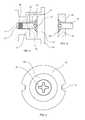
- FIG. 1is a longitudinal sectional view of a preferred embodiment of the insert of this invention with the first magnet in place and held by a male thread fastener.
- FIG. 2is a top view of the insert panel fastener of FIG. 1 .
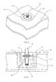
- FIG. 3shows one embodiment of the second magnet which can be used with the insert of FIGS. 1 and 2 .
- FIG. 4shows the insert of FIGS. 1 and 2 and the second magnet of FIG. 3 after it has been installed in a panel.
- FIG. 5shows in sectional view the insert of FIG. 1 with the second magnet of FIG. 3 magnetically retained therein.
- FIG. 6is a sectional view of the insert and second magnet of FIG. 5 with a device, e.g., a cell phone housing held to the screw thread projecting from the top of the second magnet.
- a devicee.g., a cell phone housing held to the screw thread projecting from the top of the second magnet.
- FIG. 7is an alternate preferred embodiment wherein the screw thread projecting from the second magnet in FIG. 5 has been eliminated and the device is affixed to the second magnet by an adhesive bond.
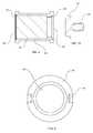
- FIG. 8is a top view of another alternate preferred embodiment of an insert wherein there is only one magnet, that being within the insert, a body of a ferromagnetic material is repeatedly attachable and detachable from said magnet due to magnetic attraction being said magnet and said ferromagnetic bodies.
- FIG. 9is a side view in half-section showing the insert of FIG. 8 .
- FIG. 10is a full sectional view of the insert of FIGS. 8 and 9 together with a member made of a ferromagnetic material such as carbon steel or stainless steel which can be held by a magnet.
- a deviceis intended to be attached to said non-magnetic member.
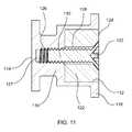
- FIG. 11is a sectional view of another embodiment of the panel insert taken along the line 11 - 11 in FIG. 12 .
- FIG. 12is a top view of the insert of FIG. 11 .
- the first magnet 22 inside the body 10is securely attached to the body by a screw 30 as is shown in FIGS. 1 and 2 .
- FIG. 3shows the second magnet 34 which when inserted into the body is attachably and detachably held by the magnet 22 in the body.
- the two magnetsare of opposite polarity.
- the central threaded element 38 in FIG. 3is an attachment point for the remote control or phone, etc., and can be replaced by adhesive if use of a screw would damage the remote control or phone.
- the insert body 10has a generally cylindrical open end 12 and a closed end 14 , and is adapted to be received in honeycomb sandwich panel 16 .
- the body 10has a circular flange 18 projecting from open end 12 .
- the flange 18preferably has spaced apart, preferably diametrically opposed, cutouts or holes 20 , one for the introduction of potting material 21 , and the other for the venting of air.
- the method of potting inserts in honeycomb panel and the installation of inserts so that the flange 18 is flush with the adjacent surface of the honeycomb panelis familiar to those skilled in the art.
- a cylindrical first magnet 22 having a generally smooth flat outer surface 24 facing the open end of body 10is snugly received in the open end 12 .
- a female thread 26is centrally disposed in opening 27 which extends into the closed end 14 of body 10 , stopping short of the terminus of the closed end.
- the first magnet 22has a centrally disposed countersunk threaded clearance hole 28 that allows the male threaded fastener 30 to mate with the female threads 26 in insert body 10 .
- a male thread fastener 30is received in thread 26 to secure the magnet 22 to insert body 10 .
- the male thread fastener 30has a head 32 which is received in the surface 24 of magnet 22 to form a surface which is flush with surface 24 , as shown in FIG. 1 .
- a second magnet 34 of opposite polarity to magnet 22having a smooth surface 36 , preferably of approximately the same diameter as magnet 22 , can be inserted and magnetically retained in the open end 12 of insert body 10 .
- the magnetic attachmentcan be overcome by ordinary manual force, so the attachment and detachment of the two magnets can be repeated as often as is required.
- FIGS. 6 and 7illustrate the practical application of the invention.
- the magnet 34may have a male thread stud 38 projecting from the surface 40 opposed to its smooth surface 36 .
- the stud 38can be threadably attached to a device such as artwork, logos, a remote control or phone.
- the stud 38can be replaced by an adhesive bonding layer 42 , as shown in FIG. 7 .
- the artwork, logos, remote control or phoneis indicated generally by the casing or frame 44 .
- the magnet 34need not be sized to the magnet 22 . Instead, the magnet 34 can be smaller and stud-like while still being held by magnet 22 .
- magnet 22need not be snugly received in the open end 12 of insert body 10 .
- magnets 22 and 34can be of any shape so long as the facing surfaces 24 and 36 are essentially smooth to provide a close abutting relationship.
- the insertcan be secured to the honeycomb panel by potting or any other means known in the art.
- the panelis preferably honeycomb. However, any type of panel normally provided with inserts may be used.
- the insertcan first be assembled to the first magnet 22 by screw 30 and then installed in the panel. Alternatively, the insert can be installed in the panel and the first magnet subsequently secured to the insert by screw 30 .
- the first magnet 22need not be held by screw 30 . Instead, the first magnet can be swagged into or adhesively bonded to the opening 12 in insert body 10 .
- the magnetsare preferably noedymium.
- the insert body 10 of the insertcan be steel, aluminum, stainless steel, titanium, or plastic of the types well-known in the art.
- the body 10is normally non-magnetic.
- insert 46has potting cutouts or holes 48 in top flange 50 .
- the interior of insert 46has an opening 52 at the top and, initially, an opening at the opposite end 54 .
- a magnet 56is snugly received in insert 46 .
- the magnet 56can be swagged in insert 46 or, as shown in FIG. 9 , the inside wall of insert 46 can be provided with an area of reduced diameter to form a projection 58 .
- the magnet 56is then held within the insert 46 between the projection 58 at one of its ends and the other end of magnet 56 is held by element 60 which can be a metal shim which is swagged into the interior of insert 46 , securing magnet 56 in place.
- the second magnetis replaced by a ferromagnetic element 62 , preferably made of carbon steel or stainless steel which can be attached to and held by magnet 56 and manually detached from said magnet.
- the ferromagnetic element 62can be provided with a threaded stud 64 . Stud 64 can be attached to devices as explained above. The stud 64 can also be eliminated and replaced by an adhesive bonding layer to adhere to a device.
- the body 110 of the inserthas a closed end 114 and an open end 112 .
- the body 110has a flange 118 .
- a magnet 122is received in the open end 112 and has a smooth surface 124 .
- the magnet 122is affixed in the central bore of said body 110 .
- the magnetic member 122is generally circular in cross-section and received in the central opening with said smooth surface being flush with the open end 112 of the body 110 .
- a female thread 128is disposed in opening 127 .
- the magnet 122has a center hole 128 .
- Fastener 130is received in thread 126 to secure magnet 122 to insert body 110 .
- the head 132 of fastener 130is received in the surface 124 of magnet 122 to form a surface flush with surface 124 .
- the outer surface of magnet 122 including head 132is flush with the surrounding flange 118 .
Landscapes
- Engineering & Computer Science (AREA)
- General Engineering & Computer Science (AREA)
- Mechanical Engineering (AREA)
- Connection Of Plates (AREA)
- Casings For Electric Apparatus (AREA)
- Supports Or Holders For Household Use (AREA)
Abstract
Description
This application is a divisional of pending application Ser. No. 13/626,262 filed Sep. 25, 2012, the disclosures of which are incorporated herein by reference.
The invention relates to magnetic temporary attachment of devices such as a phone, artwork and the like to the interior paneling of an aircraft.
Honeycomb panel is used for partitions and other interior structures in commercial aircraft. Various devices must be attached to the honeycomb panel. In order to provide attachment points, potted inserts have long been installed in honeycomb panel.
An example of a potted insert and a method for its installation in honeycomb panel is illustrated in Gauron, U.S. Pat. No. 4,812,493, FIGS. 1 to 12. These inserts have a female thread center bore adapted to receive a male thread fastener. The threaded connection is intended to secure the attached device to the panel in a way which is resistant to unauthorized manipulation and the effects of vibration. Detachment is intended to require the use of a tool. However, this threaded connection is not suitable where it is desired that the device be temporarily and securely held while at the same time being manually, repeatedly attachable and detachable from the panel. The present invention addresses this need.
The present invention relates to a magnetic insert receptacle wherein the insert has received therein a magnet or magnetically conductive stud for the purpose of temporarily yet securing affixing an item or device to an aircraft wall, table, etc. Applications include holding logos/artwork to partition walls, keeping loose objects in the aircraft cabin, portable devices (e.g., remote controls, phones, etc.) in place during takeoff/landing/turbulence and/or for general securing of lightweight yet removable features within an aircraft, yacht, etc.
A panel insert comprising an external body, preferably generally cylindrical, having at least one open end, said body having a central bore, a magnet received in said bore and having a smooth surface facing an open end of the body, said magnet being secured in the central bore of said body.
A panel insert comprising an external body having a closed end and an open end, said body having a central bore terminating at said open end, a magnet received in said bore and having a smooth surface facing said open end of the body, said magnet being affixed in the central bore of said body.
A panel insert comprising an external body having a closed end and an open end, said body having a central bore terminating at said open end, a first magnet received in said bore and having a smooth surface facing said open end of the body, said magnet being affixed in said bore, a second magnet of opposite polarity received in the open end of said body, said magnet having a surface adapted to snugly abut the smooth surface of said first magnet.
A panel insert comprising an external body having a closed end and an open end, said body having a generally cylindrical central bore extending from said closed end and terminating at said open end, a disk-like flange extending around said open end of said body such that when the insert is mounted in a panel, the flange is flush with the surface of the panel, said disk having space apart openings for receiving potting material and the venting of air, a female threaded central opening in said closed end of the body, a magnet received in said bore and having a smooth surface facing the open end of said body, a hole extending through the center of said magnet, and a male thread fastener received in said female threaded central opening to affix said magnet to said body, said male thread fastener having a head which is received flush with the surface of the magnet facing said open end of said body.
A panel insert comprising an external body having a closed end and an open end, said body having a generally cylindrical central bore extending from said closed end and terminating at said open end, a disk-like flange extending around said open end of the body such that when the insert is mounted in a panel, the flange is flush with the surface of the panel, said disk having spaced apart openings for receiving potting material and the venting of air, a female threaded central opening in said closed end of the body, a first magnet received in said bore and having a smooth surface facing the open end of said body, a hole extending through the center of said magnet, and a male thread fastener received in said female threaded central opening to affix said first magnet to said body, said male thread fastener having a head which is received flush with the surface of the magnet facing said open end of said body, a second magnet of opposite polarity received in said open end of said body and having a complementary smooth surface abutting the said smooth surface of said first magnet to permit said second magnet to be repeatedly, manually attached and detached from said first magnet.
A panel insert comprising an external body having a closed end and an open end, said body having a generally cylindrical central bore extending from said closed end and terminating at said open end, a disk-like flange extending around said open end of the body such that when the insert is mounted in a panel, the flange is flush with the surface of the panel, said disk having spaced apart openings for receiving potting material and the venting of air, a female threaded central opening in said closed end of the body, a first magnet received in said bore and having a smooth surface facing the open end of said body, a hole extending through the center of said magnet, and a male thread fastener received in said female threaded central opening to affix said first magnet to said body, said male thread fastener having a head which is received flush with the surface of the magnet facing said open end of said body, a body of ferromagnetic material received in said open end of said body and having a complementary smooth surface abutting the said smooth surface of said magnet to permit said ferromagnetic body to be repeatedly attached and detached from said magnet.
The second magnet or the ferromagnetic body is affixed to a device such as artwork, logos, a remote control or phone. The first magnet can be affixed to the panel insert body so that its exposed surface is flush with the flange of the insert and the adjacent surface of the panel. In this case, the second magnet or the body of ferromagnetic material can be simply laid on the smooth exposed surface of the magnet affixed to the insert body. The device itself (artwork logo or phone) can be made to have magnetic or ferromagnetic properties, wholly or by an attachment, which allow them to be repeatedly attachably and detachably held by the magnet affixed to the panel insert.
Turning to the drawings:
Thefirst magnet 22 inside thebody 10 is securely attached to the body by ascrew 30 as is shown inFIGS. 1 and 2 .
Turning to the drawings in more detail, theinsert body 10 has a generally cylindricalopen end 12 and a closedend 14, and is adapted to be received inhoneycomb sandwich panel 16. Thebody 10 has acircular flange 18 projecting fromopen end 12. Theflange 18 preferably has spaced apart, preferably diametrically opposed, cutouts orholes 20, one for the introduction ofpotting material 21, and the other for the venting of air. The method of potting inserts in honeycomb panel and the installation of inserts so that theflange 18 is flush with the adjacent surface of the honeycomb panel is familiar to those skilled in the art.
A cylindricalfirst magnet 22 having a generally smooth flatouter surface 24 facing the open end ofbody 10 is snugly received in theopen end 12.
Afemale thread 26 is centrally disposed in opening27 which extends into the closedend 14 ofbody 10, stopping short of the terminus of the closed end.
Thefirst magnet 22 has a centrally disposed countersunk threadedclearance hole 28 that allows the male threadedfastener 30 to mate with thefemale threads 26 ininsert body 10.
Amale thread fastener 30 is received inthread 26 to secure themagnet 22 to insertbody 10. Themale thread fastener 30 has ahead 32 which is received in thesurface 24 ofmagnet 22 to form a surface which is flush withsurface 24, as shown inFIG. 1 .
Once the insert with the first magnet has been installed in a panel, asecond magnet 34 of opposite polarity tomagnet 22, having asmooth surface 36, preferably of approximately the same diameter asmagnet 22, can be inserted and magnetically retained in theopen end 12 ofinsert body 10. The magnetic attachment can be overcome by ordinary manual force, so the attachment and detachment of the two magnets can be repeated as often as is required.
Themagnet 34 may have amale thread stud 38 projecting from thesurface 40 opposed to itssmooth surface 36.
As shown inFIG. 6 , thestud 38 can be threadably attached to a device such as artwork, logos, a remote control or phone.
Alternatively, thestud 38 can be replaced by anadhesive bonding layer 42, as shown inFIG. 7 .
The artwork, logos, remote control or phone is indicated generally by the casing orframe 44.
In another embodiment, themagnet 34 need not be sized to themagnet 22. Instead, themagnet 34 can be smaller and stud-like while still being held bymagnet 22.
Themagnet 22 need not be snugly received in theopen end 12 ofinsert body 10. In general,magnets
In use, the insert can be secured to the honeycomb panel by potting or any other means known in the art. The panel is preferably honeycomb. However, any type of panel normally provided with inserts may be used.
The insert can first be assembled to thefirst magnet 22 byscrew 30 and then installed in the panel. Alternatively, the insert can be installed in the panel and the first magnet subsequently secured to the insert byscrew 30.
Thefirst magnet 22 need not be held byscrew 30. Instead, the first magnet can be swagged into or adhesively bonded to theopening 12 ininsert body 10.
The magnets are preferably noedymium.
Theinsert body 10 of the insert can be steel, aluminum, stainless steel, titanium, or plastic of the types well-known in the art. Thebody 10 is normally non-magnetic.
In the additional alternate preferred embodiment ofFIGS. 8 to 10 , insert46 has potting cutouts orholes 48 intop flange 50. The interior ofinsert 46 has anopening 52 at the top and, initially, an opening at theopposite end 54. Amagnet 56 is snugly received ininsert 46. Themagnet 56 can be swagged ininsert 46 or, as shown inFIG. 9 , the inside wall ofinsert 46 can be provided with an area of reduced diameter to form aprojection 58. Themagnet 56 is then held within theinsert 46 between theprojection 58 at one of its ends and the other end ofmagnet 56 is held byelement 60 which can be a metal shim which is swagged into the interior ofinsert 46, securingmagnet 56 in place.
In the embodiment ofFIGS. 8 to 10 , the second magnet is replaced by aferromagnetic element 62, preferably made of carbon steel or stainless steel which can be attached to and held bymagnet 56 and manually detached from said magnet. Theferromagnetic element 62 can be provided with a threadedstud 64.Stud 64 can be attached to devices as explained above. Thestud 64 can also be eliminated and replaced by an adhesive bonding layer to adhere to a device.
InFIGS. 11 and 12 , thebody 110 of the insert has aclosed end 114 and anopen end 112. Thebody 110 has aflange 118. Amagnet 122 is received in theopen end 112 and has asmooth surface 124. Themagnet 122 is affixed in the central bore of saidbody 110. In the panel insert themagnetic member 122 is generally circular in cross-section and received in the central opening with said smooth surface being flush with theopen end 112 of thebody 110. Afemale thread 128 is disposed inopening 127. Themagnet 122 has acenter hole 128.Fastener 130 is received inthread 126 to securemagnet 122 to insertbody 110. Thehead 132 offastener 130 is received in thesurface 124 ofmagnet 122 to form a surface flush withsurface 124. The outer surface ofmagnet 122 includinghead 132 is flush with the surroundingflange 118.
Claims (5)
1. A panel insert comprising an external body having an open end and an opposed closed end,
said body having a central bore, a magnet having two ends received in said bore, one end of said magnet having a surface facing the open end of the body, said magnet being secured in said central bore of said body,
wherein the central bore is generally circular in cross-section,
wherein said insert has a flange around its open end, said flange having potting cutouts or holes therein, the interior of the insert has an opening at the open end, the magnet is snugly received in the insert, and the inside wall of the insert is provided with an area of reduced diameter to form a projection such that the said one end of the magnet is held within the insert by the projection and the other end of the magnet is secured in said insert by a closure forming the closed end of the insert body.
2. A combination comprising a honeycomb panel and a panel insert, said panel insert being snugly received in a hole in said honeycomb panel and held therein by potting material, said insert comprising an external body having an open end and an opposed closed end,
said body having a central bore, a magnet having two ends received in said bore, one end of said magnet having a surface facing the open end of the body, said magnet being secured in said central bore of said body,
wherein the central bore is generally circular in cross-section,
wherein the insert has potting cutouts or holes in a flange, the interior of the insert has an opening at the open end, the magnet is snugly received in the insert, and the inside wall of the insert is provided with an area of reduced diameter to form a projection such that the said one end of the magnet is held within the insert by the projection and the other end of the magnet is secured in said insert by an element forming the closed end of said insert body.
3. The combination ofclaim 2 wherein said element securing said magnet in place is swagged in said insert body forming the closed end of the insert.
4. The combination ofclaim 2 wherein a ferromagnetic member is attachably and detachably held in said central bore by magnetic attraction.
5. The combination ofclaim 2 wherein a ferromagnetic member is attachably and detachably held in said central bore by magnetic attraction and further including a device attached to said ferromagnetic member.
Priority Applications (1)
| Application Number | Priority Date | Filing Date | Title |
|---|---|---|---|
| US14/825,044US9732778B2 (en) | 2012-09-25 | 2015-08-12 | Magnetic panel insert mount |
Applications Claiming Priority (2)
| Application Number | Priority Date | Filing Date | Title |
|---|---|---|---|
| US13/626,262US9140279B2 (en) | 2012-09-25 | 2012-09-25 | Magnetic mount |
| US14/825,044US9732778B2 (en) | 2012-09-25 | 2015-08-12 | Magnetic panel insert mount |
Related Parent Applications (1)
| Application Number | Title | Priority Date | Filing Date |
|---|---|---|---|
| US13/626,262DivisionUS9140279B2 (en) | 2012-09-25 | 2012-09-25 | Magnetic mount |
Publications (2)
| Publication Number | Publication Date |
|---|---|
| US20150345524A1 US20150345524A1 (en) | 2015-12-03 |
| US9732778B2true US9732778B2 (en) | 2017-08-15 |
Family
ID=49301276
Family Applications (2)
| Application Number | Title | Priority Date | Filing Date |
|---|---|---|---|
| US13/626,262ActiveUS9140279B2 (en) | 2012-09-25 | 2012-09-25 | Magnetic mount |
| US14/825,044ActiveUS9732778B2 (en) | 2012-09-25 | 2015-08-12 | Magnetic panel insert mount |
Family Applications Before (1)
| Application Number | Title | Priority Date | Filing Date |
|---|---|---|---|
| US13/626,262ActiveUS9140279B2 (en) | 2012-09-25 | 2012-09-25 | Magnetic mount |
Country Status (2)
| Country | Link |
|---|---|
| US (2) | US9140279B2 (en) |
| EP (1) | EP2711563B1 (en) |
Families Citing this family (17)
| Publication number | Priority date | Publication date | Assignee | Title |
|---|---|---|---|---|
| EP2748690A4 (en)* | 2011-08-25 | 2015-08-05 | Iomounts Llc | Apparatus and methods for supporting an article |
| TWM500127U (en)* | 2014-12-19 | 2015-05-01 | Rong-Zhang Lin | Reinforcing bar coupler |
| US9991922B2 (en) | 2015-01-05 | 2018-06-05 | Iomounts, Llc | Apparatus and method for supporting an article |
| CN106304700B (en)* | 2015-05-13 | 2019-03-22 | 纬创资通(中山)有限公司 | Embedded combination seat and manufacturing method thereof, base and combined shell |
| ITUB20152752A1 (en)* | 2015-07-17 | 2015-10-17 | Giancarlo Acquaro | UNIVERSAL MECHANICAL-MAGNETIC CONNECTOR THAT ALLOWS THE CONNECTION BETWEEN THE SAME OR DIFFERENT PARTS BETWEEN THEM WITHOUT THE USE OF SCREWS AND BOLTS. |
| US10562274B1 (en) | 2016-02-22 | 2020-02-18 | Apple Inc. | Glass fastening and sealing systems |
| US10625866B2 (en) | 2017-01-12 | 2020-04-21 | Bell Helicopter Textron Inc. | Flexible foldover seat configurations for emergency egress of aircraft |
| US10604262B2 (en) | 2017-01-12 | 2020-03-31 | Bell Helicopter Textron Inc. | Flexible aircraft seat configurations |
| US10933969B2 (en)* | 2017-01-12 | 2021-03-02 | Bell Helicopter Textron Inc. | Puck attachment mechanism for flexible aircraft configuration |
| EP3568847A1 (en)* | 2017-01-13 | 2019-11-20 | Daktronics, Inc. | Mounting structures for a banner display |
| US10273998B2 (en)* | 2017-04-03 | 2019-04-30 | Spectrum Brands, Inc. | Magnetic cleat for accessory bar |
| US10655657B2 (en)* | 2018-05-28 | 2020-05-19 | Travis Hurley | Connecting apparatus |
| US10926861B2 (en) | 2018-06-04 | 2021-02-23 | Textron Innovations Inc. | Puck cover |
| US20240277117A1 (en)* | 2021-10-22 | 2024-08-22 | Steven GRABOWSKI | Magnetic fastener system |
| WO2023069627A1 (en)* | 2021-10-22 | 2023-04-27 | Grabowski Steven | Magnetic fastener system |
| US11690363B1 (en)* | 2022-06-09 | 2023-07-04 | Ben Nevis McGee | Net retention |
| CN115307006A (en)* | 2022-09-01 | 2022-11-08 | 杭州三奇建设发展有限公司 | Novel material polymorphic combinable component |
Citations (161)
| Publication number | Priority date | Publication date | Assignee | Title |
|---|---|---|---|---|
| US346452A (en) | 1886-08-03 | William natpian bakeb | ||
| US876912A (en) | 1906-10-16 | 1908-01-14 | Harvey A Pike | Flexible stay-bolt. |
| US1295868A (en) | 1918-05-03 | 1919-03-04 | Flannery Bolt Co | Stay-bolt structure. |
| US1410004A (en) | 1921-02-16 | 1922-03-21 | Flannery Bolt Co | Stay-bolt structure |
| US1811736A (en) | 1929-07-19 | 1931-06-23 | Dual Aircraft Motors Inc Ltd | Piston rod coupling |
| US1864080A (en) | 1927-12-10 | 1932-06-21 | Mechanical Rubber Co | Nonmetallic connection |
| US2429103A (en) | 1944-07-05 | 1947-10-14 | Mitchell Robert | Threaded fastener |
| US2521885A (en) | 1947-02-26 | 1950-09-12 | John G Vasquez | Magnetic retainer |
| US2631048A (en) | 1949-04-15 | 1953-03-10 | Frederick E Palmer | Rotary joint |
| US2880830A (en) | 1957-02-21 | 1959-04-07 | Frederick W Rohe | Sandwich panel and flanged insert nut assembly |
| US2979335A (en) | 1960-07-25 | 1961-04-11 | Mark W Pruitt | Combination golf club and magnetically held marker |
| US2991816A (en) | 1958-10-03 | 1961-07-11 | Gen Dynamics Corp | Fastener means with nut member having pilot portion for aligning holes in panels |
| US3009746A (en) | 1959-07-20 | 1961-11-21 | Fred L Haushalter | Bearing structure |
| US3029824A (en)* | 1957-07-26 | 1962-04-17 | Standard Packaging Corp | Smoker's article |
| US3058765A (en) | 1958-09-19 | 1962-10-16 | American Metal Prod | Preloaded ball joint assembly |
| US3111736A (en) | 1961-12-07 | 1963-11-26 | Monarch Tool & Machinery Co | Separable two-part magnetic connector |
| US3177916A (en) | 1963-02-20 | 1965-04-13 | Rosan Eng Corp | Self-aligning two-part threaded fastener unit |
| US3181850A (en) | 1962-12-20 | 1965-05-04 | Ford Motor Co | Vibration isolating device |
| US3245165A (en) | 1965-06-18 | 1966-04-12 | Hancock Telecontrol Corp | Attaching device for holding an object on a support |
| US3258285A (en) | 1964-10-01 | 1966-06-28 | Roy K Smith | Door stop and holder |
| US3262480A (en) | 1964-04-10 | 1966-07-26 | Federal Screw Works | Nut enclosed in plastic bearing member |
| US3265107A (en) | 1964-02-03 | 1966-08-09 | Multi Flex Seals Inc | Sealing threaded nut construction |
| US3282015A (en) | 1962-04-20 | 1966-11-01 | Frederick W Rohe | Moldable insert fastener with dual potting ports in head |
| US3288511A (en)* | 1965-07-20 | 1966-11-29 | John B Tavano | Two-part magnetic catch for doors or the like |
| US3289724A (en) | 1964-02-20 | 1966-12-06 | Penn Eng & Mfg Corp | Self-locking nut having secured locking ring |
| GB1056797A (en) | 1963-10-08 | 1967-01-25 | John Wright And Sons Veneers L | Securing panelling magnetically |
| US3302566A (en) | 1964-07-22 | 1967-02-07 | Paul G Blanchet | Handle and stamp body magnetically coupled |
| US3339609A (en) | 1965-08-02 | 1967-09-05 | Delron Company Inc | Floating nut insert |
| US3388627A (en) | 1966-05-13 | 1968-06-18 | George A. Tinnerman | Composite fastener assembly |
| US3392225A (en) | 1965-06-21 | 1968-07-09 | Frederick W Rohe | Method for installing molded-in inserts in sandwich panels |
| US3429598A (en) | 1965-10-15 | 1969-02-25 | Moog Industries Inc | Ball joint unit for steerable vehicle wheels |
| US3434261A (en) | 1964-03-30 | 1969-03-25 | Frederick W Rohe | Molded-in insert with floating nut |
| US3445559A (en) | 1967-02-27 | 1969-05-20 | Olympic Plastics Co Inc | Method of making a self-locking structure |
| US3468212A (en) | 1966-05-13 | 1969-09-23 | George A Tinnerman | Composite fastener |
| US3520342A (en) | 1968-05-27 | 1970-07-14 | Helmut Rieke | Self-locking threaded fastener |
| US3729040A (en) | 1971-05-26 | 1973-04-24 | Standard Pressed Steel Co | Floating replaceable anchor nut assembly |
| US3742808A (en) | 1970-11-23 | 1973-07-03 | Vsi Corp | Composite, self-sealing female fastener |
| GB1392095A (en) | 1972-07-26 | 1975-04-23 | Rawlplug Co Ltd | Fixing device |
| US3964531A (en) | 1972-02-04 | 1976-06-22 | Dzus Fastener Co., Inc. | Panel insert |
| US4027711A (en)* | 1973-11-12 | 1977-06-07 | Tummarello Natale J | Means for mounting concrete structural members |
| US4069864A (en) | 1976-06-28 | 1978-01-24 | Martin Marietta Corporation | Gas filled swivel joint for cryogenic heat pipes |
| US4092078A (en) | 1976-12-07 | 1978-05-30 | Lemforder Metallwaren Ag | Elastic connection for an axial joint with connecting linkage of a motor vehicle steering gear |
| US4117261A (en) | 1976-07-06 | 1978-09-26 | The Boeing Company | Insulating stand-off and method of assembling same |
| US4126170A (en) | 1975-06-09 | 1978-11-21 | Abbott Screw And Manufacturing Co. | Sealing nut with preformed turtleneck insert |
| US4248285A (en) | 1976-04-07 | 1981-02-03 | Christian Flaig | Safety nut and method for making |
| US4397437A (en) | 1980-07-21 | 1983-08-09 | Robroy Industries | Beam clamp |
| US4480361A (en) | 1981-12-16 | 1984-11-06 | Tamao Morita | Clasp utilizing attractive force of permanent magnet |
| US4480596A (en) | 1978-04-20 | 1984-11-06 | Tdk Corporation | Magnetic elastic lumbar belt |
| US4488844A (en) | 1982-06-07 | 1984-12-18 | Jacobson Mfg. Co., Inc. | Floating fastener retainer assembly with removable fasteners |
| US4509308A (en) | 1982-04-08 | 1985-04-09 | Messerschmitt-Boelkow-Blohm Gmbh | Mounting assembly and method for installing dowels in compound panels |
| US4577450A (en) | 1983-06-06 | 1986-03-25 | The Boeing Company | Waterproof floor panel fastening system, accessible from above |
| US4679958A (en) | 1981-10-23 | 1987-07-14 | Nifco, Inc. | Ball joint |
| US4689928A (en) | 1985-04-15 | 1987-09-01 | Dutton Hugh J | Architectural plate glass support system |
| US4725159A (en) | 1986-07-16 | 1988-02-16 | Trw Inc. | Bearing for a joint |
| EP0273515A1 (en) | 1986-12-22 | 1988-07-06 | Richard F. Gauron | Inset panel fastener and method |
| US4761860A (en) | 1987-03-27 | 1988-08-09 | American Cord & Webbing Co., Inc. | Two part grommet with interengaging projections |
| US4815920A (en) | 1986-08-22 | 1989-03-28 | Bridgestone Corporation | Lock nut with synthetic resin threading |
| US4817264A (en) | 1987-08-10 | 1989-04-04 | Shur-Lok Corporation | Fastener and assembly process |
| US4822224A (en) | 1987-11-05 | 1989-04-18 | Chrysler Motors Corporation | Harness retainer stud |
| US4846612A (en) | 1987-10-19 | 1989-07-11 | Shur-Lok Corporation | Sandwich panel fastener |
| US4872903A (en) | 1987-10-08 | 1989-10-10 | Rockwell-Cim | Screw jack safe against overload for a movable element such as a seat structure |
| US4880343A (en) | 1987-09-30 | 1989-11-14 | Matsumoto Kokan Co., Ltd. | Lock nut having lock member of shape memory recovery alloy |
| US4883399A (en) | 1988-12-05 | 1989-11-28 | Maclean-Fogg Company | Plastic encapsulated nut and washer assembly |
| US4887950A (en) | 1985-02-22 | 1989-12-19 | Bridgestone Corporation | Waterproof nut |
| US4902180A (en) | 1986-12-22 | 1990-02-20 | Gauron Richard F | Inset panel fastener |
| US4901405A (en)* | 1988-08-25 | 1990-02-20 | Grover Alfred H | Self-aligning magnetic necklace clasp |
| US4973208A (en) | 1989-08-31 | 1990-11-27 | Gauron Richard F | Inset panel fastener with floating member |
| US4981735A (en) | 1989-09-05 | 1991-01-01 | The United States Of America As Represented By The Secretary Of The Army | Two piece threaded mounting insert with adhesive for use with honeycomb composite |
| JPH03140612A (en) | 1989-10-25 | 1991-06-14 | Avibank Mfg Inc | Nut with sleeve and lock |
| US5069431A (en) | 1987-10-19 | 1991-12-03 | Nissan Motor Company, Limited | Bush assembly |
| US5092550A (en) | 1987-07-23 | 1992-03-03 | Maclean-Fogg Company | Leveling apparatus |
| US5141203A (en) | 1991-02-21 | 1992-08-25 | Westinghouse Electric Corp. | Snubber for a machinery supporting foundation |
| US5143456A (en) | 1990-11-13 | 1992-09-01 | Lemforder Metallwaren Ag | Elastic sliding bearing |
| US5146668A (en) | 1991-06-18 | 1992-09-15 | Bulent Gulistan | Method for manufacturing part for floating nut assembly |
| US5154530A (en) | 1991-03-05 | 1992-10-13 | Trw Inc. | Ball joint |
| US5158269A (en) | 1990-10-11 | 1992-10-27 | Gencorp Inc. | Dual/slipper shock mount |
| US5230580A (en) | 1991-03-23 | 1993-07-27 | Trw Ehrenreich Gmbh & Co. Kg | Ball joint |
| US5248134A (en) | 1992-02-21 | 1993-09-28 | General Motors Corporation | Snap-in upper mount assembly and method of use |
| US5261748A (en) | 1991-03-29 | 1993-11-16 | Kinugawa Rubber Ind. Co., Ltd. | Structure for bushing |
| US5266258A (en) | 1992-01-15 | 1993-11-30 | Psm International Plc | Method of sealingly seating a metal insert in a thermoplastic component |
| JPH05325466A (en) | 1992-05-22 | 1993-12-10 | Sony Corp | Method and device for attaching magnetic plate to disk substrate |
| US5295671A (en) | 1991-11-06 | 1994-03-22 | Toyoda Gosei Co., Ltd. | Vibration insulating mount |
| US5378099A (en) | 1993-07-01 | 1995-01-03 | Gauron; Richard F. | Inset panel fastener with shoulder-engaging floating member |
| US5405004A (en) | 1992-03-23 | 1995-04-11 | Vest; Gary W. | Tool and parts tray |
| US5432986A (en) | 1993-06-15 | 1995-07-18 | Sexton; Jason | Magnetic fastener |
| US5540514A (en) | 1993-11-30 | 1996-07-30 | Saint-Gobain Vitrage | Mechanical connection between a glazing element and a supporting structure |
| US5553984A (en) | 1995-01-10 | 1996-09-10 | Smith; Donald E. | Encapsulated nut |
| US5603472A (en) | 1995-06-07 | 1997-02-18 | Physical Systems, Inc. | Flush mounted panel fastener |
| US5632582A (en) | 1996-07-10 | 1997-05-27 | Gauron; Richard F. | Inset panel fastener with two-part stem |
| US5655758A (en) | 1995-03-28 | 1997-08-12 | Toyoda Gosei Co., Ltd. | Bushing for vehicle suspension |
| US5711100A (en)* | 1993-06-14 | 1998-01-27 | Elmer; William A. | Vehicle advertising sign, system and method |
| US5713706A (en) | 1995-12-19 | 1998-02-03 | Shur-Lok Corporation | Plastic composite fastener for self-cutting and frictional welding |
| US5746411A (en) | 1994-02-09 | 1998-05-05 | Michel Bruas | Suspension pad designed to be interposed between two structural elements, in particular between a frame and a container tank |
| US5779413A (en) | 1996-02-23 | 1998-07-14 | Fairchild Holding Corp. | Fastener system having improved locking element |
| US5876023A (en) | 1996-09-18 | 1999-03-02 | Lord Corporation | Vibration isolation insert for aircraft floor planels and the like |
| GB2336247A (en) | 1998-03-16 | 1999-10-13 | W E Veale & Co Limited | A clamping system using a clip-in magnet arrangement |
| US6065742A (en) | 1996-09-13 | 2000-05-23 | Lord Corporation | Multi-directional tuned vibration absorber |
| US6102610A (en) | 1994-12-21 | 2000-08-15 | United Technologies Corporation | Brittle composite structure for resiliently accomodating thermal expansion |
| US6138980A (en) | 1999-06-24 | 2000-10-31 | Lord Corporation | Pilot mounting |
| US6216833B1 (en) | 1999-07-22 | 2001-04-17 | Bridgestone/Firestone, Inc. | Vibration damper and method of making same |
| US6227751B1 (en) | 1997-11-11 | 2001-05-08 | Mero Systeme Gmbh & Co. Kg | Mount for plate-shaped components |
| US6264412B1 (en) | 1999-01-26 | 2001-07-24 | Sakura Rubber Co., Ltd. | Honeycomb panel fixing device |
| US6287064B1 (en) | 1999-12-10 | 2001-09-11 | Western Sky Industries, Inc. | Clip type fastener assembly |
| US6305656B1 (en) | 1999-02-26 | 2001-10-23 | Dash-It Usa Inc. | Magnetic coupler and various embodiments thereof |
| US6328513B1 (en) | 1999-05-19 | 2001-12-11 | Nichias Corporation | Vibration floating washer assembly and method of attaching the same to heat insulating plate |
| US6343889B1 (en) | 1998-09-28 | 2002-02-05 | Odyssey X-Treme Technologies, Inc. | Split-socket ball joint |
| GB2366832A (en) | 2000-09-13 | 2002-03-20 | Metal Merlin Ltd | Magnetic fastener |
| US20020038927A1 (en) | 2000-10-04 | 2002-04-04 | Mannesmann Boge Gmbh | Hydraulically damping rubber bearing |
| US6382865B1 (en) | 1999-06-21 | 2002-05-07 | Richard C. Paxman | Base-mounted lubricated ball joint |
| US20020056953A1 (en) | 2000-11-15 | 2002-05-16 | R.M. Wade & Co. | Shock-absorbing mount |
| US6394432B1 (en) | 1998-06-10 | 2002-05-28 | Lord Corporation | Vibration and/or shock absorbing devices and compensator elements utilized therein |
| US6443679B1 (en) | 1999-11-23 | 2002-09-03 | Schwarz Verbindings-Systeme Gmbh | Vibration-damping connecting arrangement for the detachable connection of two components with a releasing part, which can be moved on a bolt guided by a bush |
| US20020131815A1 (en) | 2001-03-15 | 2002-09-19 | Construccions Metalliques Bellapart, S.A. | System for attaching laminated glass panels |
| DE10117562A1 (en) | 2001-04-02 | 2002-10-17 | Seyit Mehmet Arslan | Magnetic fastener for foot mats in motor vehicles consists of magnet, metal plate with fastening screw, and counter part to magnet |
| US6481943B2 (en) | 2000-03-24 | 2002-11-19 | Emhart Llc | Holding element with expandable component |
| US20020175251A1 (en) | 2001-05-22 | 2002-11-28 | Robinson Christopher J. | Sensor mount attachment device |
| JP2003113825A (en) | 2001-10-04 | 2003-04-18 | Nippon Pop Rivets & Fasteners Ltd | Elastic fastening tool |
| US6588820B2 (en) | 2000-12-04 | 2003-07-08 | Cooper Technology Services, Llc | Two stage body mount rebound cushion |
| US6695295B2 (en) | 2000-11-15 | 2004-02-24 | R.M. Wade & Co. | Vibration-isolating device |
| US6715746B2 (en) | 2000-07-21 | 2004-04-06 | Lord Corporation | Vibration isolation device with load dependent stiffness |
| US6748820B2 (en) | 2000-11-09 | 2004-06-15 | Dura Global Technologies,Inc. | Self-adjusting isolator for reducing cable lash in transmission shift systems |
| US6789993B2 (en) | 2000-07-28 | 2004-09-14 | Aoyama Seisakusho Co., Ltd. | Fastener for clamping members having a certain spacing from each other while maintaining the certain spacing therebetween |
| US20040265091A1 (en) | 2003-06-30 | 2004-12-30 | Cheung Kwun-Wing W. | Universal bulkhead fitting |
| US6910670B2 (en) | 2002-10-30 | 2005-06-28 | Tokai Rubber Industries, Ltd. | Suspension rubber bushing of vertical mount type |
| US7048487B2 (en) | 2003-06-25 | 2006-05-23 | The Gates Corporation | Connector |
| US7052002B2 (en) | 2004-02-12 | 2006-05-30 | Tokai Rubber Industries, Ltd. | Vibration-damping device |
| US20060137294A1 (en) | 2004-01-13 | 2006-06-29 | Waits Jr Bobby L | Expanded fastener for a honeycomb structure and method of assembly |
| US20060237605A1 (en)* | 2005-04-26 | 2006-10-26 | Mag Clip Corporation | Magnetic attachment element |
| US7131786B2 (en) | 2001-07-20 | 2006-11-07 | Enidine Gmbh | Process and device for the damping of motion between two cylindrical parts sliding with one another in translation and friction |
| US7163200B2 (en) | 2005-03-09 | 2007-01-16 | Basf Corporation | Interlocking mount assembly for a vehicle |
| US7179039B2 (en) | 2002-11-26 | 2007-02-20 | Schwarz Verbindungs-Systeme Gmbh | Vibration-damping ring insert arrangement and component connection arrangement incorporating the same |
| US7250003B2 (en) | 2005-07-21 | 2007-07-31 | Thompson Steven L | Encapsulated fastener and method and tooling for manufacturing same |
| US7261365B2 (en) | 2005-03-09 | 2007-08-28 | Basf Corporation | Vehicle body mount assembly |
| US7275347B2 (en) | 2003-02-03 | 2007-10-02 | Hayes Interests, Inc. | Post-tension anchor seal cap |
| US20080014043A1 (en) | 2006-07-13 | 2008-01-17 | David Zasloff | Peg board mounting device |
| US20080120865A1 (en)* | 2006-11-28 | 2008-05-29 | Smith Holly M | Magnetic drying apparatus |
| US20080210835A1 (en)* | 2007-03-02 | 2008-09-04 | Gary Wayne Bagnall | Magnetic Attachment Apparatus |
| US20080227379A1 (en) | 2007-03-15 | 2008-09-18 | Chung-Liang Hung | Magnetic fan-attaching structure and magnetic attaching element thereof |
| US20080253859A1 (en) | 2007-04-12 | 2008-10-16 | Johnson Lawrence W | Cage nut fastening system |
| US7465136B2 (en) | 2005-07-11 | 2008-12-16 | Nigayama Electric Co., Ltd. | Insert nut and insert t-nut |
| DE102007032568A1 (en) | 2007-07-12 | 2009-02-05 | Fidlock Gmbh | Magnetic connector i.e. magnetic lock, has elements deformed by viscoelastic deformation on pre-determined measure under magnetic force influence and magnetic pole surface, and anchor surface laid in pre-determined opposite position |
| US7496994B1 (en) | 2007-10-04 | 2009-03-03 | Theresa Headley | Connecting device using a magnet |
| US20090194575A1 (en)* | 2005-03-21 | 2009-08-06 | R.W.H., Llc | Anchoring Pin Insertion Unit and Method |
| US7618013B2 (en) | 2004-01-14 | 2009-11-17 | Elmer William A | Magnetic assembly and method |
| WO2009142513A1 (en) | 2008-05-20 | 2009-11-26 | Roderick Nigel Redgrave | A closure mechanism |
| US20100008104A1 (en) | 2008-07-12 | 2010-01-14 | Rosenthal Horst | Point holder |
| US20100034625A1 (en) | 2008-08-08 | 2010-02-11 | Applied Materials, Inc. | Magnetic pad for end-effectors |
| US20100086377A1 (en) | 2008-10-04 | 2010-04-08 | De Mola Manuel Loret | Vibration isolation fastener insert |
| US7802953B2 (en) | 2007-03-16 | 2010-09-28 | Robert Stephen | Inset panel fastener |
| US20110001025A1 (en) | 2007-12-04 | 2011-01-06 | Fidlock Gmbh | Magnetic Coupling Device |
| US20110018665A1 (en) | 2008-05-20 | 2011-01-27 | Cedar Ridge Research, Llc. | Correlated Magnetic Assemblies for Securing Objects in a Vehicle |
| US7922135B2 (en)* | 2001-03-30 | 2011-04-12 | Robert Granata | Articulating fastener assembly |
| US8001661B2 (en) | 2005-12-01 | 2011-08-23 | Modern Muse, Inc. | Apparatus for securing ornamentation to personal items |
| US20110308048A1 (en) | 2010-06-17 | 2011-12-22 | Racca Enterprises, Inc. | Clip with magnetic detent for securing lighter to pack of cigarettes |
| US8206459B1 (en) | 2009-03-18 | 2012-06-26 | Rehabilitation Institute Of Chicago | Prosthetic-to-liner attachment mechanism |
| US20130105642A1 (en)* | 2011-10-28 | 2013-05-02 | Arielle Marq Incorporated | Magnetic apparatus for securing an object and method for magnetically securing an object |
| US20130276269A1 (en) | 2012-04-23 | 2013-10-24 | Yung-Fa SU | Belt buckle structure |
| US8568072B2 (en) | 2008-06-23 | 2013-10-29 | Toyota Jidosha Kabushiki Kaisha | Screw hole seal structure, and production method for fiber-reinforced resin member |
| US8739371B2 (en) | 2010-11-18 | 2014-06-03 | Fidlock Gmbh | Locking device |
| US8875542B2 (en)* | 2011-01-17 | 2014-11-04 | Noah Severs | Magnetic interchangeable jewelry |
| US20160047494A1 (en)* | 2009-05-13 | 2016-02-18 | Termax Corporation | Magnetic Cable Fastener |
Family Cites Families (3)
| Publication number | Priority date | Publication date | Assignee | Title |
|---|---|---|---|---|
| US4812493A (en) | 1987-04-10 | 1989-03-14 | Adhesive Coatings Co. | Dual cure rate water-based coating compositions |
| US6363584B1 (en)* | 2000-01-20 | 2002-04-02 | George Gero | Cuff link with changeable element |
| US8371141B2 (en)* | 2009-02-03 | 2013-02-12 | Magnet House Jewelry, Llc | Jewelry apparatus |
- 2012
- 2012-09-25USUS13/626,262patent/US9140279B2/enactiveActive
- 2013
- 2013-09-23EPEP13185591.8Apatent/EP2711563B1/enactiveActive
- 2015
- 2015-08-12USUS14/825,044patent/US9732778B2/enactiveActive
Patent Citations (166)
| Publication number | Priority date | Publication date | Assignee | Title |
|---|---|---|---|---|
| US346452A (en) | 1886-08-03 | William natpian bakeb | ||
| US876912A (en) | 1906-10-16 | 1908-01-14 | Harvey A Pike | Flexible stay-bolt. |
| US1295868A (en) | 1918-05-03 | 1919-03-04 | Flannery Bolt Co | Stay-bolt structure. |
| US1410004A (en) | 1921-02-16 | 1922-03-21 | Flannery Bolt Co | Stay-bolt structure |
| US1864080A (en) | 1927-12-10 | 1932-06-21 | Mechanical Rubber Co | Nonmetallic connection |
| US1811736A (en) | 1929-07-19 | 1931-06-23 | Dual Aircraft Motors Inc Ltd | Piston rod coupling |
| US2429103A (en) | 1944-07-05 | 1947-10-14 | Mitchell Robert | Threaded fastener |
| US2521885A (en) | 1947-02-26 | 1950-09-12 | John G Vasquez | Magnetic retainer |
| US2631048A (en) | 1949-04-15 | 1953-03-10 | Frederick E Palmer | Rotary joint |
| US2880830A (en) | 1957-02-21 | 1959-04-07 | Frederick W Rohe | Sandwich panel and flanged insert nut assembly |
| US3029824A (en)* | 1957-07-26 | 1962-04-17 | Standard Packaging Corp | Smoker's article |
| US3058765A (en) | 1958-09-19 | 1962-10-16 | American Metal Prod | Preloaded ball joint assembly |
| US2991816A (en) | 1958-10-03 | 1961-07-11 | Gen Dynamics Corp | Fastener means with nut member having pilot portion for aligning holes in panels |
| US3009746A (en) | 1959-07-20 | 1961-11-21 | Fred L Haushalter | Bearing structure |
| US2979335A (en) | 1960-07-25 | 1961-04-11 | Mark W Pruitt | Combination golf club and magnetically held marker |
| US3111736A (en) | 1961-12-07 | 1963-11-26 | Monarch Tool & Machinery Co | Separable two-part magnetic connector |
| US3282015A (en) | 1962-04-20 | 1966-11-01 | Frederick W Rohe | Moldable insert fastener with dual potting ports in head |
| US3181850A (en) | 1962-12-20 | 1965-05-04 | Ford Motor Co | Vibration isolating device |
| US3177916A (en) | 1963-02-20 | 1965-04-13 | Rosan Eng Corp | Self-aligning two-part threaded fastener unit |
| GB1056797A (en) | 1963-10-08 | 1967-01-25 | John Wright And Sons Veneers L | Securing panelling magnetically |
| US3265107A (en) | 1964-02-03 | 1966-08-09 | Multi Flex Seals Inc | Sealing threaded nut construction |
| US3289724A (en) | 1964-02-20 | 1966-12-06 | Penn Eng & Mfg Corp | Self-locking nut having secured locking ring |
| US3434261A (en) | 1964-03-30 | 1969-03-25 | Frederick W Rohe | Molded-in insert with floating nut |
| US3262480A (en) | 1964-04-10 | 1966-07-26 | Federal Screw Works | Nut enclosed in plastic bearing member |
| US3302566A (en) | 1964-07-22 | 1967-02-07 | Paul G Blanchet | Handle and stamp body magnetically coupled |
| US3258285A (en) | 1964-10-01 | 1966-06-28 | Roy K Smith | Door stop and holder |
| US3245165A (en) | 1965-06-18 | 1966-04-12 | Hancock Telecontrol Corp | Attaching device for holding an object on a support |
| DE1500949B1 (en) | 1965-06-21 | 1970-01-29 | Shur Lok Corp | Installation device for dowels in lightweight composite panels |
| US3392225A (en) | 1965-06-21 | 1968-07-09 | Frederick W Rohe | Method for installing molded-in inserts in sandwich panels |
| US3288511A (en)* | 1965-07-20 | 1966-11-29 | John B Tavano | Two-part magnetic catch for doors or the like |
| US3339609A (en) | 1965-08-02 | 1967-09-05 | Delron Company Inc | Floating nut insert |
| US3429598A (en) | 1965-10-15 | 1969-02-25 | Moog Industries Inc | Ball joint unit for steerable vehicle wheels |
| US3388627A (en) | 1966-05-13 | 1968-06-18 | George A. Tinnerman | Composite fastener assembly |
| US3468212A (en) | 1966-05-13 | 1969-09-23 | George A Tinnerman | Composite fastener |
| US3445559A (en) | 1967-02-27 | 1969-05-20 | Olympic Plastics Co Inc | Method of making a self-locking structure |
| US3520342A (en) | 1968-05-27 | 1970-07-14 | Helmut Rieke | Self-locking threaded fastener |
| US3635272A (en) | 1968-05-27 | 1972-01-18 | Helmut Rieke | Threaded fastening device and method of making the same |
| US3742808A (en) | 1970-11-23 | 1973-07-03 | Vsi Corp | Composite, self-sealing female fastener |
| US3729040A (en) | 1971-05-26 | 1973-04-24 | Standard Pressed Steel Co | Floating replaceable anchor nut assembly |
| US3964531A (en) | 1972-02-04 | 1976-06-22 | Dzus Fastener Co., Inc. | Panel insert |
| GB1392095A (en) | 1972-07-26 | 1975-04-23 | Rawlplug Co Ltd | Fixing device |
| US4027711A (en)* | 1973-11-12 | 1977-06-07 | Tummarello Natale J | Means for mounting concrete structural members |
| US4126170A (en) | 1975-06-09 | 1978-11-21 | Abbott Screw And Manufacturing Co. | Sealing nut with preformed turtleneck insert |
| US4248285A (en) | 1976-04-07 | 1981-02-03 | Christian Flaig | Safety nut and method for making |
| US4069864A (en) | 1976-06-28 | 1978-01-24 | Martin Marietta Corporation | Gas filled swivel joint for cryogenic heat pipes |
| US4117261A (en) | 1976-07-06 | 1978-09-26 | The Boeing Company | Insulating stand-off and method of assembling same |
| US4092078A (en) | 1976-12-07 | 1978-05-30 | Lemforder Metallwaren Ag | Elastic connection for an axial joint with connecting linkage of a motor vehicle steering gear |
| US4480596A (en) | 1978-04-20 | 1984-11-06 | Tdk Corporation | Magnetic elastic lumbar belt |
| US4397437A (en) | 1980-07-21 | 1983-08-09 | Robroy Industries | Beam clamp |
| US4679958A (en) | 1981-10-23 | 1987-07-14 | Nifco, Inc. | Ball joint |
| US4480361A (en) | 1981-12-16 | 1984-11-06 | Tamao Morita | Clasp utilizing attractive force of permanent magnet |
| US4509308A (en) | 1982-04-08 | 1985-04-09 | Messerschmitt-Boelkow-Blohm Gmbh | Mounting assembly and method for installing dowels in compound panels |
| US4488844A (en) | 1982-06-07 | 1984-12-18 | Jacobson Mfg. Co., Inc. | Floating fastener retainer assembly with removable fasteners |
| US4577450A (en) | 1983-06-06 | 1986-03-25 | The Boeing Company | Waterproof floor panel fastening system, accessible from above |
| US4887950A (en) | 1985-02-22 | 1989-12-19 | Bridgestone Corporation | Waterproof nut |
| US4689928A (en) | 1985-04-15 | 1987-09-01 | Dutton Hugh J | Architectural plate glass support system |
| US4725159A (en) | 1986-07-16 | 1988-02-16 | Trw Inc. | Bearing for a joint |
| US4815920A (en) | 1986-08-22 | 1989-03-28 | Bridgestone Corporation | Lock nut with synthetic resin threading |
| US4812193A (en) | 1986-12-22 | 1989-03-14 | Gauron Richard F | Inset panel fastener and method of using |
| EP0273515A1 (en) | 1986-12-22 | 1988-07-06 | Richard F. Gauron | Inset panel fastener and method |
| US4902180A (en) | 1986-12-22 | 1990-02-20 | Gauron Richard F | Inset panel fastener |
| US4761860A (en) | 1987-03-27 | 1988-08-09 | American Cord & Webbing Co., Inc. | Two part grommet with interengaging projections |
| US5092550A (en) | 1987-07-23 | 1992-03-03 | Maclean-Fogg Company | Leveling apparatus |
| US4817264A (en) | 1987-08-10 | 1989-04-04 | Shur-Lok Corporation | Fastener and assembly process |
| US4880343A (en) | 1987-09-30 | 1989-11-14 | Matsumoto Kokan Co., Ltd. | Lock nut having lock member of shape memory recovery alloy |
| US4872903A (en) | 1987-10-08 | 1989-10-10 | Rockwell-Cim | Screw jack safe against overload for a movable element such as a seat structure |
| US4846612A (en) | 1987-10-19 | 1989-07-11 | Shur-Lok Corporation | Sandwich panel fastener |
| US5069431A (en) | 1987-10-19 | 1991-12-03 | Nissan Motor Company, Limited | Bush assembly |
| US4822224A (en) | 1987-11-05 | 1989-04-18 | Chrysler Motors Corporation | Harness retainer stud |
| US4901405A (en)* | 1988-08-25 | 1990-02-20 | Grover Alfred H | Self-aligning magnetic necklace clasp |
| US4883399A (en) | 1988-12-05 | 1989-11-28 | Maclean-Fogg Company | Plastic encapsulated nut and washer assembly |
| US4973208A (en) | 1989-08-31 | 1990-11-27 | Gauron Richard F | Inset panel fastener with floating member |
| US4981735A (en) | 1989-09-05 | 1991-01-01 | The United States Of America As Represented By The Secretary Of The Army | Two piece threaded mounting insert with adhesive for use with honeycomb composite |
| JPH03140612A (en) | 1989-10-25 | 1991-06-14 | Avibank Mfg Inc | Nut with sleeve and lock |
| US5158269A (en) | 1990-10-11 | 1992-10-27 | Gencorp Inc. | Dual/slipper shock mount |
| US5143456A (en) | 1990-11-13 | 1992-09-01 | Lemforder Metallwaren Ag | Elastic sliding bearing |
| US5141203A (en) | 1991-02-21 | 1992-08-25 | Westinghouse Electric Corp. | Snubber for a machinery supporting foundation |
| US5154530A (en) | 1991-03-05 | 1992-10-13 | Trw Inc. | Ball joint |
| US5230580A (en) | 1991-03-23 | 1993-07-27 | Trw Ehrenreich Gmbh & Co. Kg | Ball joint |
| US5261748A (en) | 1991-03-29 | 1993-11-16 | Kinugawa Rubber Ind. Co., Ltd. | Structure for bushing |
| US5146668A (en) | 1991-06-18 | 1992-09-15 | Bulent Gulistan | Method for manufacturing part for floating nut assembly |
| US5295671A (en) | 1991-11-06 | 1994-03-22 | Toyoda Gosei Co., Ltd. | Vibration insulating mount |
| US5266258A (en) | 1992-01-15 | 1993-11-30 | Psm International Plc | Method of sealingly seating a metal insert in a thermoplastic component |
| US5248134A (en) | 1992-02-21 | 1993-09-28 | General Motors Corporation | Snap-in upper mount assembly and method of use |
| US5405004A (en) | 1992-03-23 | 1995-04-11 | Vest; Gary W. | Tool and parts tray |
| JPH05325466A (en) | 1992-05-22 | 1993-12-10 | Sony Corp | Method and device for attaching magnetic plate to disk substrate |
| USRE44480E1 (en) | 1993-06-14 | 2013-09-10 | William A. Elmer | Vehicle advertising sign, system and method |
| US5711100A (en)* | 1993-06-14 | 1998-01-27 | Elmer; William A. | Vehicle advertising sign, system and method |
| US5432986A (en) | 1993-06-15 | 1995-07-18 | Sexton; Jason | Magnetic fastener |
| US5378099A (en) | 1993-07-01 | 1995-01-03 | Gauron; Richard F. | Inset panel fastener with shoulder-engaging floating member |
| US5540514A (en) | 1993-11-30 | 1996-07-30 | Saint-Gobain Vitrage | Mechanical connection between a glazing element and a supporting structure |
| US5746411A (en) | 1994-02-09 | 1998-05-05 | Michel Bruas | Suspension pad designed to be interposed between two structural elements, in particular between a frame and a container tank |
| US6102610A (en) | 1994-12-21 | 2000-08-15 | United Technologies Corporation | Brittle composite structure for resiliently accomodating thermal expansion |
| US5553984A (en) | 1995-01-10 | 1996-09-10 | Smith; Donald E. | Encapsulated nut |
| US5655758A (en) | 1995-03-28 | 1997-08-12 | Toyoda Gosei Co., Ltd. | Bushing for vehicle suspension |
| US5603472A (en) | 1995-06-07 | 1997-02-18 | Physical Systems, Inc. | Flush mounted panel fastener |
| US5713706A (en) | 1995-12-19 | 1998-02-03 | Shur-Lok Corporation | Plastic composite fastener for self-cutting and frictional welding |
| US5779413A (en) | 1996-02-23 | 1998-07-14 | Fairchild Holding Corp. | Fastener system having improved locking element |
| US5632582A (en) | 1996-07-10 | 1997-05-27 | Gauron; Richard F. | Inset panel fastener with two-part stem |
| US6065742A (en) | 1996-09-13 | 2000-05-23 | Lord Corporation | Multi-directional tuned vibration absorber |
| US5876023A (en) | 1996-09-18 | 1999-03-02 | Lord Corporation | Vibration isolation insert for aircraft floor planels and the like |
| US5876024A (en) | 1996-09-18 | 1999-03-02 | Lord Corporation | Vibration isolation insert for aircraft floor panels and the like |
| US6227751B1 (en) | 1997-11-11 | 2001-05-08 | Mero Systeme Gmbh & Co. Kg | Mount for plate-shaped components |
| GB2336247A (en) | 1998-03-16 | 1999-10-13 | W E Veale & Co Limited | A clamping system using a clip-in magnet arrangement |
| US6394432B1 (en) | 1998-06-10 | 2002-05-28 | Lord Corporation | Vibration and/or shock absorbing devices and compensator elements utilized therein |
| US6343889B1 (en) | 1998-09-28 | 2002-02-05 | Odyssey X-Treme Technologies, Inc. | Split-socket ball joint |
| US6264412B1 (en) | 1999-01-26 | 2001-07-24 | Sakura Rubber Co., Ltd. | Honeycomb panel fixing device |
| US6305656B1 (en) | 1999-02-26 | 2001-10-23 | Dash-It Usa Inc. | Magnetic coupler and various embodiments thereof |
| US6328513B1 (en) | 1999-05-19 | 2001-12-11 | Nichias Corporation | Vibration floating washer assembly and method of attaching the same to heat insulating plate |
| US6382865B1 (en) | 1999-06-21 | 2002-05-07 | Richard C. Paxman | Base-mounted lubricated ball joint |
| US6138980A (en) | 1999-06-24 | 2000-10-31 | Lord Corporation | Pilot mounting |
| US6216833B1 (en) | 1999-07-22 | 2001-04-17 | Bridgestone/Firestone, Inc. | Vibration damper and method of making same |
| US6443679B1 (en) | 1999-11-23 | 2002-09-03 | Schwarz Verbindings-Systeme Gmbh | Vibration-damping connecting arrangement for the detachable connection of two components with a releasing part, which can be moved on a bolt guided by a bush |
| US6287064B1 (en) | 1999-12-10 | 2001-09-11 | Western Sky Industries, Inc. | Clip type fastener assembly |
| US6481943B2 (en) | 2000-03-24 | 2002-11-19 | Emhart Llc | Holding element with expandable component |
| US6715746B2 (en) | 2000-07-21 | 2004-04-06 | Lord Corporation | Vibration isolation device with load dependent stiffness |
| US6789993B2 (en) | 2000-07-28 | 2004-09-14 | Aoyama Seisakusho Co., Ltd. | Fastener for clamping members having a certain spacing from each other while maintaining the certain spacing therebetween |
| GB2366832A (en) | 2000-09-13 | 2002-03-20 | Metal Merlin Ltd | Magnetic fastener |
| US20020038927A1 (en) | 2000-10-04 | 2002-04-04 | Mannesmann Boge Gmbh | Hydraulically damping rubber bearing |
| US6748820B2 (en) | 2000-11-09 | 2004-06-15 | Dura Global Technologies,Inc. | Self-adjusting isolator for reducing cable lash in transmission shift systems |
| US6695295B2 (en) | 2000-11-15 | 2004-02-24 | R.M. Wade & Co. | Vibration-isolating device |
| US20020056953A1 (en) | 2000-11-15 | 2002-05-16 | R.M. Wade & Co. | Shock-absorbing mount |
| US6588820B2 (en) | 2000-12-04 | 2003-07-08 | Cooper Technology Services, Llc | Two stage body mount rebound cushion |
| US20020131815A1 (en) | 2001-03-15 | 2002-09-19 | Construccions Metalliques Bellapart, S.A. | System for attaching laminated glass panels |
| US7922135B2 (en)* | 2001-03-30 | 2011-04-12 | Robert Granata | Articulating fastener assembly |
| DE10117562A1 (en) | 2001-04-02 | 2002-10-17 | Seyit Mehmet Arslan | Magnetic fastener for foot mats in motor vehicles consists of magnet, metal plate with fastening screw, and counter part to magnet |
| US20020175251A1 (en) | 2001-05-22 | 2002-11-28 | Robinson Christopher J. | Sensor mount attachment device |
| US7131786B2 (en) | 2001-07-20 | 2006-11-07 | Enidine Gmbh | Process and device for the damping of motion between two cylindrical parts sliding with one another in translation and friction |
| JP2003113825A (en) | 2001-10-04 | 2003-04-18 | Nippon Pop Rivets & Fasteners Ltd | Elastic fastening tool |
| US6910670B2 (en) | 2002-10-30 | 2005-06-28 | Tokai Rubber Industries, Ltd. | Suspension rubber bushing of vertical mount type |
| US7179039B2 (en) | 2002-11-26 | 2007-02-20 | Schwarz Verbindungs-Systeme Gmbh | Vibration-damping ring insert arrangement and component connection arrangement incorporating the same |
| US7275347B2 (en) | 2003-02-03 | 2007-10-02 | Hayes Interests, Inc. | Post-tension anchor seal cap |
| US7048487B2 (en) | 2003-06-25 | 2006-05-23 | The Gates Corporation | Connector |
| US20040265091A1 (en) | 2003-06-30 | 2004-12-30 | Cheung Kwun-Wing W. | Universal bulkhead fitting |
| US20060137294A1 (en) | 2004-01-13 | 2006-06-29 | Waits Jr Bobby L | Expanded fastener for a honeycomb structure and method of assembly |
| US7618013B2 (en) | 2004-01-14 | 2009-11-17 | Elmer William A | Magnetic assembly and method |
| US7052002B2 (en) | 2004-02-12 | 2006-05-30 | Tokai Rubber Industries, Ltd. | Vibration-damping device |
| US7163200B2 (en) | 2005-03-09 | 2007-01-16 | Basf Corporation | Interlocking mount assembly for a vehicle |
| US7261365B2 (en) | 2005-03-09 | 2007-08-28 | Basf Corporation | Vehicle body mount assembly |
| US20090194575A1 (en)* | 2005-03-21 | 2009-08-06 | R.W.H., Llc | Anchoring Pin Insertion Unit and Method |
| US20060237605A1 (en)* | 2005-04-26 | 2006-10-26 | Mag Clip Corporation | Magnetic attachment element |
| US7465136B2 (en) | 2005-07-11 | 2008-12-16 | Nigayama Electric Co., Ltd. | Insert nut and insert t-nut |
| US7250003B2 (en) | 2005-07-21 | 2007-07-31 | Thompson Steven L | Encapsulated fastener and method and tooling for manufacturing same |
| US8001661B2 (en) | 2005-12-01 | 2011-08-23 | Modern Muse, Inc. | Apparatus for securing ornamentation to personal items |
| US20080014043A1 (en) | 2006-07-13 | 2008-01-17 | David Zasloff | Peg board mounting device |
| US20080120865A1 (en)* | 2006-11-28 | 2008-05-29 | Smith Holly M | Magnetic drying apparatus |
| US20080210835A1 (en)* | 2007-03-02 | 2008-09-04 | Gary Wayne Bagnall | Magnetic Attachment Apparatus |
| US20080227379A1 (en) | 2007-03-15 | 2008-09-18 | Chung-Liang Hung | Magnetic fan-attaching structure and magnetic attaching element thereof |
| US7802953B2 (en) | 2007-03-16 | 2010-09-28 | Robert Stephen | Inset panel fastener |
| US20080253859A1 (en) | 2007-04-12 | 2008-10-16 | Johnson Lawrence W | Cage nut fastening system |
| DE102007032568A1 (en) | 2007-07-12 | 2009-02-05 | Fidlock Gmbh | Magnetic connector i.e. magnetic lock, has elements deformed by viscoelastic deformation on pre-determined measure under magnetic force influence and magnetic pole surface, and anchor surface laid in pre-determined opposite position |
| US7496994B1 (en) | 2007-10-04 | 2009-03-03 | Theresa Headley | Connecting device using a magnet |
| US20110001025A1 (en) | 2007-12-04 | 2011-01-06 | Fidlock Gmbh | Magnetic Coupling Device |
| WO2009142513A1 (en) | 2008-05-20 | 2009-11-26 | Roderick Nigel Redgrave | A closure mechanism |
| US20110018665A1 (en) | 2008-05-20 | 2011-01-27 | Cedar Ridge Research, Llc. | Correlated Magnetic Assemblies for Securing Objects in a Vehicle |
| US8568072B2 (en) | 2008-06-23 | 2013-10-29 | Toyota Jidosha Kabushiki Kaisha | Screw hole seal structure, and production method for fiber-reinforced resin member |
| US20100008104A1 (en) | 2008-07-12 | 2010-01-14 | Rosenthal Horst | Point holder |
| US20100034625A1 (en) | 2008-08-08 | 2010-02-11 | Applied Materials, Inc. | Magnetic pad for end-effectors |
| US20100086377A1 (en) | 2008-10-04 | 2010-04-08 | De Mola Manuel Loret | Vibration isolation fastener insert |
| US8206459B1 (en) | 2009-03-18 | 2012-06-26 | Rehabilitation Institute Of Chicago | Prosthetic-to-liner attachment mechanism |
| US20160047494A1 (en)* | 2009-05-13 | 2016-02-18 | Termax Corporation | Magnetic Cable Fastener |
| US20110308048A1 (en) | 2010-06-17 | 2011-12-22 | Racca Enterprises, Inc. | Clip with magnetic detent for securing lighter to pack of cigarettes |
| US8739371B2 (en) | 2010-11-18 | 2014-06-03 | Fidlock Gmbh | Locking device |
| US8875542B2 (en)* | 2011-01-17 | 2014-11-04 | Noah Severs | Magnetic interchangeable jewelry |
| US20130105642A1 (en)* | 2011-10-28 | 2013-05-02 | Arielle Marq Incorporated | Magnetic apparatus for securing an object and method for magnetically securing an object |
| US20130276269A1 (en) | 2012-04-23 | 2013-10-24 | Yung-Fa SU | Belt buckle structure |
Also Published As
| Publication number | Publication date |
|---|---|
| EP2711563B1 (en) | 2016-11-02 |
| US9140279B2 (en) | 2015-09-22 |
| EP2711563A3 (en) | 2015-12-02 |
| US20150345524A1 (en) | 2015-12-03 |
| EP2711563A2 (en) | 2014-03-26 |
| US20140084119A1 (en) | 2014-03-27 |
Similar Documents
| Publication | Publication Date | Title |
|---|---|---|
| US9732778B2 (en) | Magnetic panel insert mount | |
| US10696403B2 (en) | Aircraft monument floor mounting system | |
| US9003662B2 (en) | Insert and method for anchoring in a cored panel | |
| CA2787421A1 (en) | Apparatus for attaching a member to a core-stiffened structure and a combination thereof | |
| US7195436B1 (en) | Inset panel fastener | |
| US20110008125A1 (en) | Threaded flanged bushing for fastening applications | |
| US20160245318A1 (en) | Penetrated floating nut | |
| US20070297869A1 (en) | Through insert with floating capability | |
| CN105916659A (en) | Insert and method of attaching insert to structure | |
| WO2020040160A1 (en) | Magnetic product and magnet hook | |
| US11592173B1 (en) | Fastenerless shelves and candle holders | |
| JP7085720B2 (en) | Mounting tool for non-magnetic material | |
| CN109154348B (en) | Vibration isolation support | |
| US7896309B1 (en) | Magnetic alignment tool for foam inserts contained within precast wall panels | |
| CN220281671U (en) | Aluminum honeycomb floor mooring ring | |
| US20160107740A1 (en) | Inspection device and method for use | |
| CN206368612U (en) | Concealed sliding catch | |
| KR20140140670A (en) | Solar panel mounting structure | |
| US10412499B2 (en) | Loudspeaker driver/exciter with unique design to facilitate mounting | |
| CA3090021A1 (en) | Adjustable potted insert | |
| KR200498449Y1 (en) | An interior ventilation diffuser in which a cover coupling structure using magnetic force is applied | |
| JP3068354U (en) | Door open condition holder | |
| FI128464B (en) | Fastener | |
| CN209191339U (en) | A kind of Quick Release quick-release structure of composite material cellular board | |
| US20210039826A1 (en) | Methods and devices for integrating and adapting products with tethering systems |
Legal Events
| Date | Code | Title | Description |
|---|---|---|---|
| STCF | Information on status: patent grant | Free format text:PATENTED CASE | |
| MAFP | Maintenance fee payment | Free format text:PAYMENT OF MAINTENANCE FEE, 4TH YEAR, LARGE ENTITY (ORIGINAL EVENT CODE: M1551); ENTITY STATUS OF PATENT OWNER: LARGE ENTITY Year of fee payment:4 | |
| AS | Assignment | Owner name:ROYAL BANK OF CANADA, CANADA Free format text:SECURITY INTEREST;ASSIGNOR:THE YOUNG ENGINEERS, INC.;REEL/FRAME:056538/0813 Effective date:20210611 | |
| MAFP | Maintenance fee payment | Free format text:PAYMENT OF MAINTENANCE FEE, 8TH YEAR, LARGE ENTITY (ORIGINAL EVENT CODE: M1552); ENTITY STATUS OF PATENT OWNER: LARGE ENTITY Year of fee payment:8 |