US9730721B2 - Ultrasonic system and method for minimally invasive tissue treatment - Google Patents
Ultrasonic system and method for minimally invasive tissue treatmentDownload PDFInfo
- Publication number
- US9730721B2 US9730721B2US14/514,262US201414514262AUS9730721B2US 9730721 B2US9730721 B2US 9730721B2US 201414514262 AUS201414514262 AUS 201414514262AUS 9730721 B2US9730721 B2US 9730721B2
- Authority
- US
- United States
- Prior art keywords
- cannula
- delivery device
- ultrasonic energy
- deliver
- housing
- Prior art date
- Legal status (The legal status is an assumption and is not a legal conclusion. Google has not performed a legal analysis and makes no representation as to the accuracy of the status listed.)
- Active
Links
Images


Classifications
- A—HUMAN NECESSITIES
- A61—MEDICAL OR VETERINARY SCIENCE; HYGIENE
- A61B—DIAGNOSIS; SURGERY; IDENTIFICATION
- A61B17/00—Surgical instruments, devices or methods
- A61B17/32—Surgical cutting instruments
- A61B17/320068—Surgical cutting instruments using mechanical vibrations, e.g. ultrasonic
- A—HUMAN NECESSITIES
- A61—MEDICAL OR VETERINARY SCIENCE; HYGIENE
- A61B—DIAGNOSIS; SURGERY; IDENTIFICATION
- A61B17/00—Surgical instruments, devices or methods
- A61B17/32—Surgical cutting instruments
- A61B17/3205—Excision instruments
- A—HUMAN NECESSITIES
- A61—MEDICAL OR VETERINARY SCIENCE; HYGIENE
- A61B—DIAGNOSIS; SURGERY; IDENTIFICATION
- A61B8/00—Diagnosis using ultrasonic, sonic or infrasonic waves
- A61B8/44—Constructional features of the ultrasonic, sonic or infrasonic diagnostic device
- A61B8/4444—Constructional features of the ultrasonic, sonic or infrasonic diagnostic device related to the probe
- A—HUMAN NECESSITIES
- A61—MEDICAL OR VETERINARY SCIENCE; HYGIENE
- A61B—DIAGNOSIS; SURGERY; IDENTIFICATION
- A61B17/00—Surgical instruments, devices or methods
- A61B17/32—Surgical cutting instruments
- A61B17/320068—Surgical cutting instruments using mechanical vibrations, e.g. ultrasonic
- A61B2017/32007—Surgical cutting instruments using mechanical vibrations, e.g. ultrasonic with suction or vacuum means
- A—HUMAN NECESSITIES
- A61—MEDICAL OR VETERINARY SCIENCE; HYGIENE
- A61B—DIAGNOSIS; SURGERY; IDENTIFICATION
- A61B17/00—Surgical instruments, devices or methods
- A61B17/32—Surgical cutting instruments
- A61B17/320068—Surgical cutting instruments using mechanical vibrations, e.g. ultrasonic
- A61B2017/320084—Irrigation sleeves
- A—HUMAN NECESSITIES
- A61—MEDICAL OR VETERINARY SCIENCE; HYGIENE
- A61B—DIAGNOSIS; SURGERY; IDENTIFICATION
- A61B90/00—Instruments, implements or accessories specially adapted for surgery or diagnosis and not covered by any of the groups A61B1/00 - A61B50/00, e.g. for luxation treatment or for protecting wound edges
- A61B90/36—Image-producing devices or illumination devices not otherwise provided for
- A61B90/37—Surgical systems with images on a monitor during operation
- A61B2090/378—Surgical systems with images on a monitor during operation using ultrasound
- A—HUMAN NECESSITIES
- A61—MEDICAL OR VETERINARY SCIENCE; HYGIENE
- A61B—DIAGNOSIS; SURGERY; IDENTIFICATION
- A61B90/00—Instruments, implements or accessories specially adapted for surgery or diagnosis and not covered by any of the groups A61B1/00 - A61B50/00, e.g. for luxation treatment or for protecting wound edges
- A61B90/20—Surgical microscopes characterised by non-optical aspects
Definitions
- a number of surgical procedureshave been described to treat chronic lateral epicondylalgia.
- Particular open techniquestypically require open surgical dissection down to the pathological tissue and therefore necessitate repair of the surgically compromised normal tissue.
- Some arthroscopic techniquescan be slightly less invasive, but these arthroscopic elbow techniques have been associated with neurological complications and may require the use of a high-cost operating suite and associated personnel.
- Various percutaneous techniqueshave been described which release, ablate or resect the pathological tissue. These percutaneous techniques, however, generally require a noticeable skin incision, some surgical dissection, and the afore-mentioned use of a high-cost operating suite and supportive equipment and personnel.
- the systemincludes a delivery device and a controller adapted to deliver a power signal to the delivery device.
- the delivery deviceis adapted to deliver ultrasonic energy to musculoskeletal tissue and includes a housing portion, an ultrasound transducer, and a tip portion.
- the housing portiondefines a compartment and has an aspiration conduit and an irrigation conduit.
- the ultrasound transduceris disposed in the compartment of the housing portion and is adapted to translate a power signal to ultrasonic energy.
- the tip portionis coupled to the housing portion and is adapted to deliver fluid coming through the irrigation conduit to a musculoskeletal tissue site and to deliver detritus coming from the musculoskeletal tissue site through the aspiration channel.
- the tip portionincludes a cannula and a sleeve.
- the cannulahas a proximal portion and a distal portion, where the cannula is coupled to the ultrasound transducer to receive ultrasonic energy from the ultrasound transducer and deliver the ultrasonic energy to the musculoskeletal tissue site.
- the sleeveis adapted for percutaneous insertion and forms a lumen receiving the proximal portion of the cannula.
- a delivery deviceis connected to a vacuum source, a fluid source, and a power signal source.
- the delivery devicehas a housing portion maintaining an ultrasound transducer and a tip portion having a sleeve and a cannula.
- the cannulais coupled to the ultrasound transducer and received in the sleeve to define a covered portion and an exposed portion.
- Ultrasonic energyis generated by sending a power signal from the power signal source to the ultrasound transducer.
- the ultrasonic energyis transmitted from the ultrasound transducer to the cannula, such that the exposed portion of the cannula delivers ultrasonic energy at a frequency that is pre-selected to debride musculoskeletal tissue upon percutaneous insertion of the tip portion.
- FIG. 1shows a system for accessing and treating tissue, according to some embodiments.
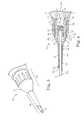
- FIG. 2is a longitudinal section of a delivery device of the system of FIG. 1 , according to some embodiments.
- FIG. 3is an enlarged perspective view of a tip portion of the delivery device of FIG. 1 , according to some embodiments.
- FIG. 4is a longitudinal section of the view of FIG. 3 , according to some embodiments.
- FIG. 5is a schematic view of a controller of the system of FIG. 1 , according to some embodiments.
- FIG. 6is a schematic view of a user interface of the controller of FIG. 5 , according to some embodiments.
- FIGS. 7A, 7B, and 7Cshow a tubing cassette of the controller of FIG. 5 , according to some embodiments.
- FIG. 8shows a tenotomy procedure using the system of FIG. 1 under ultrasonic guidance, according to some embodiments.
- the systemincludes a delivery device that is pre-tuned to an ultrasonic energy frequency range selected for debridement of pathologic musculoskeletal tissue.
- the delivery devicealso termed a hand piece, includes echogenic material and/or etching to facilitate ultrasonic imaging and is adapted for percutaneous insertion without producing a noticeable skin incision. Portions of the system, including the delivery device and associated tubing set, are optionally adapted to be discarded after a single use.
- a high-frequency ultrasound transducer and associated ultrasound imaging equipmentprovide visual detail of the tendinopathic changes of lateral epicondylalgia, so pathologic tissue is better identified at the time of a procedure without the need to cut the skin. Thereafter, pathologic tissue or other target tissue is accessible and treatable using the system without a noticeable skin incision.
- One procedureincludes an ultrasound-guided percutaneous tenotomy for chronic lateral epicondylalgia, where the use of ultrasound equipment and echogenic instrumentation helps provide precise localization and treatment of the pathological tissue under real-time guidance while minimizing trauma to non-affected tissues.
- Other tissues in the elbow joint and in other parts of the bodyare contemplated for treatment using systems described herein.
- systemsadditionally or alternatively serve to deliver therapeutic agents to the site before or after tissue is treated or are used to accomplish a variety of tissue treatments (e.g., tissue disruption, debridement, decortication, or others).
- FIG. 1shows a system 10 for percutaneously accessing and acting upon target tissue while helping reduce collateral trauma, according to some embodiments.
- the percutaneous, minimally-invasive nature of the system 10facilitates treatment of a patient in an office setting under local anesthesia. Treatment in an office setting is advantageous in several respects, including patient comfort and convenience and avoiding costs associated with operating room time and general anesthesia, for example.
- the system 10includes a delivery device 12 adapted to deliver ultrasonic energy to musculoskeletal tissue and a controller 14 connected to the delivery device 12 (e.g., via wired communication, wireless communication, or combinations thereof).
- various components of the delivery device 12 contemplated for tissue contactare formed of biocompatible and/or other suitable materials depending upon implementation.
- the delivery device 12is optionally ergonomically designed, adapted to be hand held (e.g., as a stylet) or otherwise adapted to be manually operated using a single hand. In other implementations, the delivery device 12 is adapted to be manipulated automatically or semi-automatically (e.g., as part of a robotic system).
- FIG. 2shows a longitudinal section of the delivery device 12 , according to some embodiments. As shown in FIG. 2 , the delivery device 12 includes a housing portion 20 , an ultrasound transducer 22 maintained within the housing portion 20 , and a tip portion 24 that is removably coupled to the housing portion 20 , according to some embodiments.
- the housing portion 20provides means for maintaining the transducer 22 and forms an irrigation conduit 26 and a vacuum conduit 28 , where the housing portion 20 includes a body 30 and a mounting post 32 received in the body 30 . As illustrated, portions of the irrigation and vacuum conduits 26 , 28 are formed by the body 30 and mounting post 32 .
- the body 30defines an inner compartment 34 and extends from a proximal end 36 to a distal end 38 , the body 30 forming a nose portion 40 toward the distal end 38 , a grip portion 42 proximal from the nose portion 40 , and a fluid bypass 44 separated from and extending adjacent to the inner compartment 34 .
- the body 30is formed of Acrylonitrile Butadiene Styrene, although a variety of materials are contemplated.
- the inner compartment 34is generally an elongate space within the body 30 , extending through the grip portion 42 distally through the nose portion 40 .
- the inner compartment 34is adapted to receive the ultrasound transducer 22 and the mounting post 32 , as well as any other incorporated components (e.g., a power signal source such as a battery and control circuitry, or other features) and forms a part of the irrigation conduit 26 in combination with the mounting post 32 as subsequently described.
- the nose portion 40is generally narrowed in diameter relative to the grip portion 42 . As shown, the nose portion 40 optionally includes external threading 50 for releasably mating with the tip portion 24 .
- the grip portion 42includes a contoured profile to enhance grip and facilitate manual control of the device 12 by a user.
- the fluid bypass 44extends along an external portion of the grip portion 42 according to some implementations, where the fluid bypass 44 defines a hollow lumen 54 having an inlet 56 from the inner compartment 34 near the proximal end 36 of the body 30 and an outlet 58 back into the inner compartment 34 . As subsequently described, the fluid bypass 44 also forms a portion of the irrigation conduit 26 .
- the mounting post 32includes a neck 64 , a collar 66 , and a stem 68 and defines an inner lumen 70 which forms a portion of the vacuum conduit 28 .
- the neck 64is elongate and tubular and includes internal threading 72 within the inner lumen 70 .
- the collar 66has a relatively larger diameter than the neck 64 and resides intermediate the neck 64 and stem 68 , where the neck 64 extends distally from the collar 66 and the stem 68 extends proximally from the collar 66 .
- the collar 66optionally includes a gasket 74 , or O-ring, for forming a fluid seal with the inner compartment 34 of the body 30 proximal to the outlet 58 of the fluid bypass 44 .
- the stem 68has a relatively smaller diameter than the collar 66 and is adapted to coaxially receive the ultrasound transducer 22 according to some embodiments.
- the stem 68is optionally formed of first and second tubular members 68 A, 68 B coupled via complementary threading and/or a frictional fit, for example.
- the neck 64 , the collar 66 , and the first tubular member 68 A of the stem 68are formed of a material that is suitable for conveying ultrasonic energy.
- the neck 64 , collar 66 , and the first tubular member 68 Aare optionally formed of a stainless steel alloy, although a variety of materials are contemplated.
- the second tubular member 68 B of the stem 68 Ais formed of a dampening or insulating material, such as a relatively soft polymeric material, for reducing or inhibiting proximal transmission of ultrasonic energy or other undesirable ultrasonic energy transmission.
- the second tubular member 68 Bis optionally formed of polytetrafluoroethylene, although a variety of materials are contemplated.
- the ultrasound transducer 22is maintained in the inner compartment 34 of the housing portion 20 by the mounting post 32 and provides means for generating ultrasonic energy from a power signal.
- the ultrasonic energyis optionally applied in a pulsed fashion or continuous fashion as desired.
- the transducer 22optionally takes a variety of forms, but according to some embodiments includes an enclosure 80 housing a plurality of piezoelectric crystals 82 and electrodes and a power conduit 84 for carrying a power signal to the transducer 22 .
- the transducer 22is adapted to translate a power signal from the controller 14 to ultrasonic energy.
- the enclosure 80 of the transducer 22is mounted to first tubular member 68 A of the stem 68 such that ultrasonic energy generated by the transducer 22 is conveyed into and through the mounting post 32 distally to the neck 64 of the mounting post 32 .
- the transducer 22is optionally adapted to generate longitudinal vibration, transverse vibration, or combinations thereof at desired frequencies.
- the number and configuration of the piezoelectric crystals 82are optionally varied to modify the ultrasonic frequency used for tissue treatment.
- the vacuum conduit 28is generally formed by the mounting post 32 , where the inner lumen 70 of the mounting post 32 provides an aspiration duct through the housing portion 20 .
- the second tubular member 68 Bis optionally secured to the proximal end 36 of the body 30 and capped with a connector as desired.
- the second tubular member 68 Bis configured to include a removable filter and/or a collection container for collecting and filtering detritus from the target site.
- the irrigation conduit 26is formed by a combination of the body 30 and mounting post 32 of the housing portion 20 .
- assembly of the housing portion 20 and the mounting post 32includes coaxially receiving the mounting post 32 within the inner compartment 34 of the body 30 such that the gasket 74 engages the body 30 proximal to the outlet 58 of the fluid bypass 44 .
- the mounting post 32is optionally frictionally fit, adhered, welded, or otherwise secured within the body 30 according to various embodiments.
- the power conduit 84 of the transducer 22is extended distally from the enclosure 80 , secured to the proximal end 36 of the body 30 , and is optionally capped with a connector as desired.
- the irrigation conduit 26is defined by a first portion 26 A, a second portion 26 B, a third portion 26 C, and a fourth portion 26 D.
- the first portion 26 Aoptionally includes a tubular connector secured to the body 30 at the proximal end 36 and coupled to the inlet 56 of the fluid bypass 44 .
- the second portion 26 Bincludes the fluid bypass 44 .
- the third portion 26 Cincludes a portion of the inner compartment 34 between the neck 64 of the mounting post 32 and the body 30 that is distal to the collar 66 of the mounting post 32 and proximal to the nose portion 40 of the body 30 .
- the fourth portion 26 Dincludes a part of the inner compartment 34 between the nose portion 40 of the body 30 and the neck 64 of the mounting post 32 .
- fluid flow F passing into the irrigation conduit 28 in a distal directionpasses sequentially through the first, second, third, and fourth portions 26 A, 26 B, 26 C, 26 D with fluid encircling, or circumscribing the neck 64 of the mounting post 32 .
- the tip portion 24is adapted to be coupled to the housing portion 20 , deliver fluid coming through the irrigation conduit 26 to a target site, deliver detritus flow D coming from the target site into the vacuum conduit 28 , and deliver ultrasonic energy from the transducer 22 (conveyed via the mounting post 32 ) to the target site.
- the tip portion 24provides means for transmitting the ultrasonic energy to a percutaneous musculoskeletal site at a pre-tuned frequency selected to debride musculoskeletal tissue.
- FIG. 3is an enlarged isometric view of the tip portion 24 with the body portion 22 of the device 12 being largely cut away and FIG. 4 is a longitudinal section of the view of FIG. 3 , according to some embodiments.
- the tip portion 24defines a distal section 24 A adapted for percutaneous insertion without having to form an incision in the skin and a proximal section 24 B adapted for coupling to the housing portion 20 .
- the tip portion 24includes a cannula 90 and a sleeve 92 covering a section of the cannula 90 to define a covered portion 90 A and an exposed portion 90 B of the cannula 90 .
- the tip portion 24also defines an irrigation conduit 96 and a vacuum conduit 98 .
- the cannula 90is a generally hollow tubular member having a distal, insertion portion 100 and a proximal, coupling portion 102 .
- the cannula 90also defines an inner lumen 104 extending longitudinally through the insertion and coupling portions 100 , 102 .
- the cannula 90is formed of an echogenic, biocompatible material suitable for conveying ultrasonic energy.
- the cannula 90is optionally formed of a stainless steel alloy according to various embodiments.
- the cannula 90is covered or coated with echogenic material.
- the coupling portion 102 of the cannula 90includes a threaded base 108 and a flange 110 extending distally from the threaded base 108 .
- the threaded base 108is adapted to mate with the internal threading 72 of the mounting post 32 with the flange 110 abutting the mounting post 32 .
- the flange 110has a relatively larger diameter than the threaded base 108 and necks down in diameter to transition to the insertion portion 100 .
- the insertion portion 100 of the cannula 90extends smoothly from the coupling portion 102 of the cannula 90 to a terminal end 114 and is adapted for percutaneous insertion.
- the terminal end 114 of the insertion portion 100is formed at a sharp angle or in other embodiments is simply squared off (not shown). Additionally, the insertion portion 100 optionally includes serrated edges or other surface features (not shown) for enhancing ultrasonic debridement.
- the insertion portion 100 of the cannula 90has a size of about 12 gauge or less, about 12 gauge to about 25 gauge, or about 14 gauge to about 22 gauge, for example.
- the insertion portion 100has a lateral width of about 2.5 mm or less, about 2.2 mm to about 0.4 mm, or about 2.1 mm to about 0.5 mm, for example.
- the length of the insertion portion 100is about 3.0 inches to about 0.25 inches, about 2.7 inches to about 0.5 inches, or about 2.5 inches to about 1.0 inch, for example.
- the sleeve 92is a generally hollow tubular member adapted to extend over the covered portion 90 B of the cannula 90 .
- the sleeve 92reduces unwanted, collateral transmission of heat, ultrasonic energy, or other byproducts of the ultrasonic energy being conveyed along the covered portion 90 B of the cannula 90 and also helps provide a path for irrigation fluid to the exposed portion 90 A of the cannula 90 .
- the sleeve 92reduces or eliminates damage to non-target body tissues as a result of unwanted transmission of ultrasonic energy.
- the sleeve 92has a proximal, coupling portion 116 and a distal, insertion portion 118 extending from the coupling portion 116 and defining an inner lumen 120 .
- the sleeve 92 or a portion thereofis optionally formed of an echogenic, biocompatible material suitable for dampening products of ultrasonic energy (e.g., heat and vibration).
- the sleeve 92is coated with an echogenic material.
- the sleeve 92is formed of a material exhibiting a differential echogenicity to that of the cannula 90 .
- both the cannula 90 and sleeve 92facilitate ultrasonic imaging and separate identification during percutaneous insertion.
- the sleeve 92is formed of an echogenic polytetrafluoroethylene, although other materials are contemplated.
- the coupling portion 116 of the sleeve 92includes internal threading 126 adapted to mate with nose portion 40 of the body 30 and necks down in diameter to transition to the insertion portion 118 of the sleeve 92 .
- the coupling portion 116also includes a gasket 128 or O-ring for forming a fluid seal with the nose portion 40 .
- the insertion portion 118 of the sleeve 92extends smoothly from the coupling portion 116 to a terminal end 130 and is adapted for percutaneous insertion.
- the terminal end 130 of the insertion portion 118is optionally formed with a sharp angle or in other embodiments is simply squared off (not shown).
- the insertion portion 118is adapted to leave the exposed portion 90 B of the cannula 90 a length of about 10 mm or less, for example between from 2 mm to about 10 mm, although a variety of dimensions are contemplated.
- the insertion portion 118 of the sleeve 92has a size of about 12 gauge or less, about 12 gauge to about 25 gauge, or about 14 gauge to about 22 gauge, for example.
- the insertion portion 118has a lateral width of about 2.5 mm or less, about 2.2 mm to about 0.4 mm, or about 2.1 mm to about 0.5 mm, for example.
- the length of the insertion portion 118is about 3.0 inches to about 0.25 inches, about 2.7 inches to about 0.5 inches, or about 2.5 inches to about 1.0 inch, for example.
- the vacuum conduit 98is generally formed by the cannula 90 , where the inner lumen 104 of the cannula 90 provides an aspiration duct through the tip portion 24 with an inlet at the terminal end 114 of the cannula 90 .
- the irrigation conduit 96is formed upon securing the cannula 90 and the sleeve 92 relative to one another.
- the cannula 90 and sleeve 92are separately secured to the housing portion 20 of the delivery device 12 and do not contact one another.
- the cannula 90 and the sleeve 92define a gap between them to form the irrigation conduit 96 of the tip portion 24 , with an inlet 96 A into the irrigation conduit 96 being defined between the coupling portions 100 , 116 of the cannula 90 and the sleeve 92 , the inlet 96 A being positioned distal to the gasket 128 .
- An outlet from the irrigation conduit 96 Bis defined between the terminal end 130 of the sleeve 92 and the cannula 90 .
- fluid F passing into the irrigation conduit 96 in a distal directionpasses from the irrigation conduit 26 into the inlet 96 A and out from the outlet 96 B with fluid generally encircling, or circumscribing the insertion portion 100 of the cannula 90 and being directed toward the exposed portion 90 B of the cannula 90 .
- assembly of the delivery device 12includes removably securing the tip portion 24 to the housing portion by screwing the tip portion 24 onto the housing portion 20 with the coupling portion 102 of the cannula 90 coming into close contact with the neck 64 of the mounting post 32 such that ultrasonic energy generated by the transducer 22 is transferred from the mounting post 32 to the cannula 90 and vacuum is able to be pulled through the vacuum conduits 28 , 98 .
- the gasket 74 of the tip portion 24seals sleeve 92 to the nose portion 40 such that fluid is able to be delivered through the irrigation conduits 26 , 96 .
- the insertion portions 100 , 118 of the tip portion 24help facilitate atraumatic skin and soft tissue penetration—also described as percutaneous access without a need for a separate incision—under ultrasonic imaging.
- the delivery device 12is pre-tuned to a selected ultrasonic energy frequency or frequency range. For example, it has surprisingly been found that an ultrasonic energy frequency range from about 25 kHz to about 29 kHz effectively debrides pathologic musculoskeletal tissue (e.g., scar tissue associated with a tendon) while reducing the likelihood of trauma to healthy soft tissue.
- Various features of the delivery device 12influence the ultrasonic energy frequency being delivered from the exposed portion 90 B of the cannula 90 , including size, shape, and material of the mounting post 32 , size, shape, and material of the cannula 90 , and configuration of the transducer 22 (including size, shape, and number of piezoelectric crystals, for example).
- FIG. 5is a schematic view of the controller 14 , according to some embodiments.
- the controller 14includes a housing 200 ; a command module 202 including a user interface 204 , a power source 206 , and a processor 207 ; a vacuum source 208 ; an irrigation source 210 ; and a tubing cassette 212 .
- the housing 200is generally shown in FIG. 1 and serves to house the various components and provide connector ports, for example.
- the command module 202is adapted to control flow from the vacuum source 208 , control flow from the irrigation source 210 , power the delivery device 12 , and send and receive instructions to and from a user via the user interface 204 , where the processor 207 of the command module 202 includes software and hardware (e.g., ASIC or general purposes ICs, memory, ports, etc.) for providing means to generate and deliver a power signal to the delivery device 12 .
- the command module 202includes signal filter means 207 A for delivering a conditioned power signal (e.g., a sinusoidal power signal at a selected amplitude and frequency) to the delivery device 12 .
- a conditioned power signale.g., a sinusoidal power signal at a selected amplitude and frequency
- the user interface 204includes a touch screen system and provides a means for controlling the system 10 via a sequentially-oriented operation process as will be subsequently described.
- the power source 206optionally includes a battery, a capacitor, a transformer connected to an external power source, such as a wall socket, combinations thereof, or other means for providing electrical power to the system 10 .
- the power source 206directly or indirectly delivers power to the various components of the controller 14 as appropriate.
- the vacuum source 208is optionally a vacuum pump (e.g., a peristaltic pump) disposed within the housing 200 , though in other embodiments the vacuum source 208 is a connection to an external vacuum source (e.g., “house” vacuum), or other source for providing vacuum or aspiration flow D.
- the controller 14also optionally includes a collection container 208 A for receiving detritus, fluid, or other matter being aspirated by the aspiration flow D.
- the irrigation source 210includes a reservoir of irrigant (e.g., saline) that is pressurized by gravity, a plunger (e.g., a syringe), or a pump (e.g., a peristaltic pump operated by the controller 14 and optionally disposed within the housing 200 ) to generate fluid flow F.
- the controller 14also optionally includes a valve actuator 214 for directing fluid flow F into the vacuum conduits 28 , 98 of the delivery device 12 , for example to for flushing purposes.
- FIG. 6shows a display of the user interface 204 .
- the user interface 204provides a user (not shown) an intuitive sequence for operating the system 10 as will be described in greater detail below.
- the user interface 204includes a prime phase 220 , a purge phase 222 , and a reset phase 224 and allows sequential operation of the delivery device 12 starting with an ultrasound level selection 230 , an irrigation level selection 232 , and an aspiration level selection 234 , where a user is allowed to first select the ultrasound level 230 , then the irrigation level 232 , and finally the aspiration level 234 in sequence when operating the system 10 .
- the selections 230 , 232 , 234are illuminated sequentially, first with the ultrasound level selection 230 , and a user is not allowed to make a subsequent selection until the selection at hand has been made.
- the ultrasound energy and irrigant, or fluid floware generally delivered concurrently, while aspiration flow is delivered intermittently.
- the ultrasound energy and irrigant flowoptionally cease during aspiration and are restarted once treatment is reinitiated.
- irrigant flowceases and ultrasound energy continues during aspiration, although some of the beneficial effects from using irrigant during ultrasonic treatment (e.g., continuous tip cooling and tissue emulsification, as well as others) are potentially reduced by such operation.
- the tubing cassette 212is removable from the housing 200 and includes a housing 296 , a valve 298 , a vacuum line 300 , and an irrigation line 302 (designated by broken lines) maintained by the housing 296 , the vacuum and irrigation lines 300 , 302 providing connections between the vacuum source 208 and the delivery device 12 and between the irrigation source 210 and the delivery device 12 .
- the vacuum line 300is also optionally connected to the collection container 208 A as previously referenced.
- the vacuum and irrigation lines 300 , 302include a plurality of interconnected segments of medical tubing, although unitary constructs are a potential option as well.
- the collection container 208 Ais shown generally separate from the cassette 212 , in some embodiments the collection container 208 A is maintained by, formed as a part of, or is a component within the cassette 212 .
- the cassette 212provides means for connecting the vacuum line 300 to the vacuum source 208 in a relatively sterile manner.
- the vacuum source 208includes a peristaltic pump
- the cassette 212includes a seat structure 296 A for causing the vacuum line 300 to engage a pump drive 208 B of the vacuum source 208 that generates aspiration flow in the vacuum line 300 .
- FIG. 7Ashows an interior side of the tubing cassette 212 and FIG. 7B shows a bottom side of the tubing cassette 212 , according to some embodiments.
- FIG. 7Cis a schematic view of the tubing cassette 212 , according to some embodiments.
- the tubing cassette 212includes a housing 296 , a seat structure 296 A, a valve 298 , a vacuum line 300 , and an irrigation line 302 (the vacuum and irrigation lines 300 , 302 optionally being collectively referred to as a tubing set).
- the pump drive 208 BFIG.
- the vacuum source 208e.g., a peristaltic pump
- the valve 298is engaged by the valve actuator 214 to press the valve 298 closed such that flow from the irrigation line 302 will not travel through the vacuum line 300 to the delivery device 12 (designated generally by a broken line rectangle in FIG. 7C ).
- the valve 298is released and fluid is able to flow into the vacuum line 300 to the device and through the vacuum conduits 28 , 98 .
- the irrigant flowing through the irrigation line 302is optionally gravity pressurized or otherwise forced through the system 10 .
- the housing portion 20 of the delivery device 12includes or is connectable to one or more complementary working instruments (not shown), such as a trocar or percutaneous imaging head.
- Assembly of the system 10includes remotely connecting the delivery device 12 to the controller 14 , where the controller 14 is a separate, remote module from the delivery device 12 .
- the delivery device 12 and the controller 14or portions thereof, are formed as a single unit.
- a power line 304is used to remotely connect the controller 14 to the power conduit 84 ( FIG. 2 ) of the transducer 22 such that the controller 14 is able to supply a power signal to the delivery device 14 .
- the tubing cassette 212is removably coupled to the housing 200 of the controller 14 and the vacuum line 300 is connected to the vacuum conduit 28 ( FIG. 2 ) and the irrigation line 302 is connected to the irrigation source 210 ( FIG. 2 ).
- a user(not shown) is then manipulates the delivery device 12 under ultrasonic guidance and control delivery of ultrasonic energy, fluid flow, and vacuum flow using the interface 204 of the controller 14 , according to some embodiment.
- FIG. 8illustrates a method of delivering ultrasonic energy to a target musculoskeletal tissue site under ultrasonic imaging.
- the distal section 24 A ( FIG. 2 ) of the tip portion 24is adapted to penetrate the skin and soft tissue, thereby facilitating percutaneous access to target musculoskeletal tissue site.
- advancement of the distal section 24 A of the tip portion 24 to a target musculoskeletal tissue site 400is optionally performed under guidance of an ultrasound imaging system 402 including a high-frequency ultrasound transducer 404 (e.g., a frequency greater than about 10 MHz) and an imaging device 406 .
- the imaging system 402in combination with the echogenic nature of the tip portion 24 , permits intra-operative identification of the target tissue site 400 in need of treatment and an ability to percutaneously deliver ultrasonic energy from the exposed portion 90 A of the cannula 90 to the target tissue site 400 .
- Some methods of delivering ultrasonic energy to the target tissue site 400include connecting the delivery device 12 to the vacuum source 208 , the irrigation source 210 , and the power source 206 of the controller 14 (directly or via the command module 202 ).
- Ultrasonic energyis generated by sending a power signal from the command module 202 to the ultrasound transducer 22 .
- the ultrasonic energyis transmitted from the ultrasound transducer 22 to the cannula 90 , such that the exposed portion 90 B of the cannula 90 delivers ultrasonic energy at a frequency that is pre-selected to debride musculoskeletal tissue upon percutaneous insertion of the distal section 24 A of the tip portion 24 to the target musculoskeletal tissue site 400 .
- the user interface 204is optionally operated by a user to sequentially start up the delivery device 12 , including initiating ultrasonic energy delivery, irrigation flow to the device 12 , and aspiration flow from the device 12 .
- the tubing cassette 212is removed from the controller 14 , discarded, and replaced with a second, sterile tubing cassette (not shown) and is either pre-connected or subsequently connected to a second, sterile delivery device (not shown) to sterilize the system 10 for a new procedure.
- a plurality of disposable delivery devices similar to the delivery device 12are provided with corresponding disposable cassettes, such as the cassette 212 for each delivery device.
- Individually pre-tuning the devices to an appropriate ultrasonic energy frequency, such as that previously described, before delivery to the userremoves a need to test and adjust power signal parameters or delivery device configurations prior to or during each procedure.
- a single use cassette/delivery device kitis set up or configured prior to delivery to the end user, is then used in a treatment procedure, and is optionally discarded at the end of the procedure, thereby reducing operation time, a requisite skill level for “tuning” the system 10 , and/or additional components or systems for tuning the delivery device 12 .
- the combination of the cassette 212 and delivery device 12eliminates a need to sterilize equipment before a procedure, as all components that come into contact with bodily fluids are pre-sterilized and discarded at the end of the procedure.
- the system 10is used in any of a variety of procedures.
- the system 10is used to perform an ultrasound-guided percutaneous tenotomy.
- Some methodsinclude the target tissue site 400 being pathologic tissues (e.g., a region of scar tissue associated with a tendon 410 ), where the pathologic tissue is identified using high frequency ultrasonic imaging, the tip portion 24 is percutaneously delivered, and in particular the distal section 24 A, to the target tissue site 400 under ultrasonic imaging, and ultrasonic energy is delivered through the cannula 90 to debride the musculoskeletal tissue (e.g., scar tissue) forming the target tissue site 400 .
- pathologic tissuese.g., a region of scar tissue associated with a tendon 410
- the tip portion 24is percutaneously delivered, and in particular the distal section 24 A, to the target tissue site 400 under ultrasonic imaging
- ultrasonic energyis delivered through the cannula 90 to debride the musculoskeletal tissue (e.g., scar tissue
- Some methodsinclude identifying the target tissue site 400 entirely at the time of a procedure without cutting the skin of the patient.
- the delivery device 12is pre-tuned to deliver ultrasonic energy at a frequency that reduces the likelihood of trauma to healthy soft tissue while promoting debridement of the pathologic tissue.
- the percutaneous, minimally invasive nature of such a procedurefacilitates access and treatment of such body tissue as part of an office-based procedure under local anesthesia.
- the patientis discharged to home after a short period of in-office observation due to the minimally invasive nature of the procedure (e.g., as no local anesthesia would be necessary).
- a short period of in-office observationdue to the minimally invasive nature of the procedure (e.g., as no local anesthesia would be necessary).
- post-procedure painis typically variable, but often ranges from essentially no pain to moderately severe pain lasting less than 72 hours.
- various embodiments of the system 10provide for an office-based procedure under local anesthesia, thereby resulting in cost-savings to the patient by avoiding the costs of operating room time, where a patient may only need ice or cooling packs for analgesia and edema control after the treatment.
Landscapes
- Health & Medical Sciences (AREA)
- Life Sciences & Earth Sciences (AREA)
- Surgery (AREA)
- Engineering & Computer Science (AREA)
- Molecular Biology (AREA)
- Animal Behavior & Ethology (AREA)
- Veterinary Medicine (AREA)
- Biomedical Technology (AREA)
- Heart & Thoracic Surgery (AREA)
- Medical Informatics (AREA)
- Public Health (AREA)
- Nuclear Medicine, Radiotherapy & Molecular Imaging (AREA)
- General Health & Medical Sciences (AREA)
- Dentistry (AREA)
- Mechanical Engineering (AREA)
- Physics & Mathematics (AREA)
- Biophysics (AREA)
- Pathology (AREA)
- Radiology & Medical Imaging (AREA)
- Surgical Instruments (AREA)
Abstract
Description
Claims (17)
Priority Applications (2)
| Application Number | Priority Date | Filing Date | Title |
|---|---|---|---|
| US14/514,262US9730721B2 (en) | 2009-12-31 | 2014-10-14 | Ultrasonic system and method for minimally invasive tissue treatment |
| US14/830,315US9888937B2 (en) | 2009-12-31 | 2015-08-19 | System and method for minimally invasive tissue treatment using ultrasonic cannula |
Applications Claiming Priority (2)
| Application Number | Priority Date | Filing Date | Title |
|---|---|---|---|
| US12/650,832US9795404B2 (en) | 2009-12-31 | 2009-12-31 | System and method for minimally invasive ultrasonic musculoskeletal tissue treatment |
| US14/514,262US9730721B2 (en) | 2009-12-31 | 2014-10-14 | Ultrasonic system and method for minimally invasive tissue treatment |
Related Parent Applications (1)
| Application Number | Title | Priority Date | Filing Date |
|---|---|---|---|
| US12/650,832ContinuationUS9795404B2 (en) | 2009-12-31 | 2009-12-31 | System and method for minimally invasive ultrasonic musculoskeletal tissue treatment |
Related Child Applications (1)
| Application Number | Title | Priority Date | Filing Date |
|---|---|---|---|
| US14/830,315ContinuationUS9888937B2 (en) | 2009-12-31 | 2015-08-19 | System and method for minimally invasive tissue treatment using ultrasonic cannula |
Publications (2)
| Publication Number | Publication Date |
|---|---|
| US20150039005A1 US20150039005A1 (en) | 2015-02-05 |
| US9730721B2true US9730721B2 (en) | 2017-08-15 |
Family
ID=44188379
Family Applications (3)
| Application Number | Title | Priority Date | Filing Date |
|---|---|---|---|
| US12/650,832Active2034-02-14US9795404B2 (en) | 2009-12-31 | 2009-12-31 | System and method for minimally invasive ultrasonic musculoskeletal tissue treatment |
| US14/514,262ActiveUS9730721B2 (en) | 2009-12-31 | 2014-10-14 | Ultrasonic system and method for minimally invasive tissue treatment |
| US14/830,315ActiveUS9888937B2 (en) | 2009-12-31 | 2015-08-19 | System and method for minimally invasive tissue treatment using ultrasonic cannula |
Family Applications Before (1)
| Application Number | Title | Priority Date | Filing Date |
|---|---|---|---|
| US12/650,832Active2034-02-14US9795404B2 (en) | 2009-12-31 | 2009-12-31 | System and method for minimally invasive ultrasonic musculoskeletal tissue treatment |
Family Applications After (1)
| Application Number | Title | Priority Date | Filing Date |
|---|---|---|---|
| US14/830,315ActiveUS9888937B2 (en) | 2009-12-31 | 2015-08-19 | System and method for minimally invasive tissue treatment using ultrasonic cannula |
Country Status (7)
| Country | Link |
|---|---|
| US (3) | US9795404B2 (en) |
| EP (1) | EP2519169B1 (en) |
| CN (1) | CN102917656B (en) |
| AU (1) | AU2010339574B2 (en) |
| CA (1) | CA2786152C (en) |
| ES (1) | ES2885228T3 (en) |
| WO (1) | WO2011082219A1 (en) |
Cited By (3)
| Publication number | Priority date | Publication date | Assignee | Title |
|---|---|---|---|---|
| US11253285B2 (en) | 2016-04-04 | 2022-02-22 | University Of Utah Research Foundation | Subcutaneous cutting device |
| US11406415B2 (en) | 2012-06-11 | 2022-08-09 | Tenex Health, Inc. | Systems and methods for tissue treatment |
| US11457937B2 (en) | 2014-09-02 | 2022-10-04 | Tenex Health, Inc. | Subcutaneous wound debridement |
Families Citing this family (26)
| Publication number | Priority date | Publication date | Assignee | Title |
|---|---|---|---|---|
| AU2009215477B2 (en)* | 2008-02-20 | 2014-10-23 | Mayo Foundation For Medical Education And Research | Systems, devices and methods for accessing body tissue |
| CA2715895A1 (en)* | 2008-02-20 | 2009-08-27 | Mayo Foundation For Medical Education And Research | Ultrasound guided systems and methods |
| US9795404B2 (en) | 2009-12-31 | 2017-10-24 | Tenex Health, Inc. | System and method for minimally invasive ultrasonic musculoskeletal tissue treatment |
| US9149291B2 (en) | 2012-06-11 | 2015-10-06 | Tenex Health, Inc. | Systems and methods for tissue treatment |
| US20150250494A1 (en)* | 2012-11-26 | 2015-09-10 | Sanusi Umar | Ultrasonic Follicle Unit Extraction Device and Method |
| CN105073045A (en)* | 2013-03-13 | 2015-11-18 | 柯惠Lp公司 | Clamp ultrasound probe for lung surgery |
| US20160096040A1 (en)* | 2014-10-02 | 2016-04-07 | Tenex Health, Inc. | Laminated Needles and Methods of Making and Using Same |
| US9763689B2 (en)* | 2015-05-12 | 2017-09-19 | Tenex Health, Inc. | Elongated needles for ultrasonic applications |
| CN106175877B (en)* | 2015-08-14 | 2019-04-02 | 北京宏仁凝瑞科技发展有限公司 | Ultrasonic surgical blade system |
| CA3029756C (en) | 2016-04-25 | 2023-10-31 | Integra Lifesciences Nr Ireland Limited | Flue for ultrasonic aspiration surgical horn |
| USD820441S1 (en) | 2016-06-13 | 2018-06-12 | Integra Lifesciences Nr Ireland Limited | Surgical handpiece nosecone |
| US12109352B2 (en) | 2016-05-20 | 2024-10-08 | Integra Lifesciences Enterprises, Lllp | Ergonomic tubing attachment for medical apparatus |
| CA3029759A1 (en) | 2016-05-24 | 2017-11-30 | Integra Lifesciences Nr Ireland Limited | Ergonomic tubing attachment for medical apparatus |
| WO2018000102A1 (en) | 2016-07-01 | 2018-01-04 | Swan Cytologics Inc. | Method and apparatus for extracting and delivery of entities |
| EP3541305B1 (en)* | 2016-11-16 | 2020-12-23 | Integra Lifesciences NR Ireland Limited | Ultrasonic surgical handpiece |
| US10687840B1 (en) | 2016-11-17 | 2020-06-23 | Integra Lifesciences Nr Ireland Limited | Ultrasonic transducer tissue selectivity |
| US11096568B2 (en)* | 2017-04-06 | 2021-08-24 | Boston Scientific Scimed, Inc. | Access device methods of using the same |
| US11369513B2 (en)* | 2017-11-22 | 2022-06-28 | Surgical Design Corporation | Low-cost disposable ultrasonic surgical handpiece |
| EP3773266A4 (en) | 2018-04-06 | 2022-01-19 | Tendonova Corporation | IMPROVED TISSUE TREATMENT DEVICES AND METHODS OF USE THEREOF |
| CN119791782A (en)* | 2018-09-24 | 2025-04-11 | 史赛克公司 | Ultrasonic surgical handpiece assembly |
| CN112888389B (en)* | 2018-10-23 | 2024-10-01 | 塔拉斯有限责任公司 | Safety assembly for performing endodermal radiofrequency therapy |
| WO2020183472A1 (en) | 2019-03-13 | 2020-09-17 | Sonidental Ltd | An ultrasonic irrigator device for in-body cleaning and disinfection |
| CN110680460B (en)* | 2019-09-25 | 2021-09-07 | 江苏邦士医疗科技有限公司 | Ultrasonic surgical operation system capable of improving electroacoustic conversion efficiency |
| US12144887B2 (en) | 2020-05-18 | 2024-11-19 | Agitated Solutions Inc. | Guiding musculoskeletal procedures |
| JP7678085B2 (en)* | 2020-08-14 | 2025-05-15 | ジャイラス エーシーエムアイ インク ディー/ビー/エー オリンパス サージカル テクノロジーズ アメリカ | Stone fragment capture system for lithotripsy systems. |
| US12144563B1 (en)* | 2021-03-15 | 2024-11-19 | Agitated Solutions Inc. | Ultrasound-guided procedures |
Citations (95)
| Publication number | Priority date | Publication date | Assignee | Title |
|---|---|---|---|---|
| US3575622A (en) | 1969-08-28 | 1971-04-20 | Gen Motors Corp | Rotor resistor assembly for ac induction motors |
| US3589363A (en) | 1967-07-25 | 1971-06-29 | Cavitron Corp | Material removal apparatus and method employing high frequency vibrations |
| US3990452A (en) | 1975-06-13 | 1976-11-09 | Fibra-Sonics, Inc. | Medical machine for performing surgery and treating using ultrasonic energy |
| US4188952A (en) | 1973-12-28 | 1980-02-19 | Loschilov Vladimir I | Surgical instrument for ultrasonic separation of biological tissue |
| US4428748A (en) | 1980-04-09 | 1984-01-31 | Peyman Gholam A | Combined ultrasonic emulsifier and mechanical cutter for surgery |
| US4515583A (en) | 1983-10-17 | 1985-05-07 | Coopervision, Inc. | Operative elliptical probe for ultrasonic surgical instrument and method of its use |
| US4531934A (en) | 1982-04-13 | 1985-07-30 | Gorkovsky Gosudarstvenny Meditsinsky Institute Imini S.M. Kirova | Apparatus for the fragmentation and aspiration of ocular tissue |
| US4867141A (en) | 1986-06-18 | 1989-09-19 | Olympus Optical Co., Ltd. | Medical treatment apparatus utilizing ultrasonic wave |
| US4870953A (en) | 1987-11-13 | 1989-10-03 | Donmicheal T Anthony | Intravascular ultrasonic catheter/probe and method for treating intravascular blockage |
| US4920954A (en) | 1988-08-05 | 1990-05-01 | Sonic Needle Corporation | Ultrasonic device for applying cavitation forces |
| US5038756A (en) | 1989-10-30 | 1991-08-13 | Storz Instrument Company | Needle interface boot for ultrasonic surgical instrument |
| US5042461A (en) | 1988-05-17 | 1991-08-27 | Sumitomo Bakelite Company Limited | Horn used in an ultrasonic surgical operating instrument |
| US5267954A (en) | 1991-01-11 | 1993-12-07 | Baxter International Inc. | Ultra-sound catheter for removing obstructions from tubular anatomical structures such as blood vessels |
| US5275607A (en) | 1991-09-23 | 1994-01-04 | Visionary Medical, Inc. | Intraocular surgical scissors |
| US5344395A (en) | 1989-11-13 | 1994-09-06 | Scimed Life Systems, Inc. | Apparatus for intravascular cavitation or delivery of low frequency mechanical energy |
| US5413556A (en) | 1992-02-05 | 1995-05-09 | Inventive Systems, Inc. | Phacoemulsification handpiece |
| US5417654A (en) | 1994-02-02 | 1995-05-23 | Alcon Laboratories, Inc. | Elongated curved cavitation-generating tip for disintegrating tissue |
| US5480379A (en) | 1991-05-22 | 1996-01-02 | La Rosa; Antonio | Ultrasonic dissector and detacher for atherosclerotic plaque and method of using same |
| US5514086A (en) | 1994-09-22 | 1996-05-07 | Sonique Surgical Systems, Inc. | Multipiece ultrasonic probe for liposuction |
| US5562609A (en) | 1994-10-07 | 1996-10-08 | Fibrasonics, Inc. | Ultrasonic surgical probe |
| US5580347A (en) | 1991-07-31 | 1996-12-03 | Mentor Ophthalmics, Inc. | Controlling operation of handpieces during ophthalmic surgery |
| US5626563A (en) | 1993-01-12 | 1997-05-06 | Minnesota Mining And Manufacturing Company | Irrigation system with tubing cassette |
| US5814016A (en) | 1991-07-16 | 1998-09-29 | Heartport, Inc. | Endovascular system for arresting the heart |
| US5910110A (en) | 1995-06-07 | 1999-06-08 | Mentor Ophthalmics, Inc. | Controlling pressure in the eye during surgery |
| US5911700A (en) | 1997-03-11 | 1999-06-15 | Microaire Surgical Instruments | Power assisted liposuction and lipoinjection equipment |
| USD418916S (en) | 1998-09-16 | 2000-01-11 | Mentor Ophthalmics, Inc. | Tube set for surgical instrument |
| US6033375A (en) | 1997-12-23 | 2000-03-07 | Fibrasonics Inc. | Ultrasonic probe with isolated and teflon coated outer cannula |
| US6077285A (en) | 1998-06-29 | 2000-06-20 | Alcon Laboratories, Inc. | Torsional ultrasound handpiece |
| US6102046A (en) | 1995-11-22 | 2000-08-15 | Arthrocare Corporation | Systems and methods for electrosurgical tissue revascularization |
| CN2402273Y (en) | 1999-12-25 | 2000-10-25 | 李保灿 | Automatic cervical intervertebral disc rotary-removal and aspiration therapeutical apparatus |
| US6206014B1 (en) | 1999-03-26 | 2001-03-27 | American Optisurgical Incorporated | Automated system for rinsing a fluid line of a medical system |
| US6214017B1 (en) | 1998-09-25 | 2001-04-10 | Sherwood Services Ag | Ultrasonic surgical apparatus |
| US6234993B1 (en) | 1999-11-04 | 2001-05-22 | Microsurgical Technology, Inc. | Low profile phaco handpiece |
| US6270471B1 (en) | 1997-12-23 | 2001-08-07 | Misonix Incorporated | Ultrasonic probe with isolated outer cannula |
| EP0709077B1 (en) | 1991-10-08 | 2002-03-27 | Surgical Design Corporation | Ultrasonic handpiece |
| US6379351B1 (en) | 1997-08-27 | 2002-04-30 | Arthrocare Corporation | Electrosurgical method for the removal of pacemaker leads |
| US20020068930A1 (en) | 1995-11-22 | 2002-06-06 | Arthrocare Corporation | Systems and methods for electrosurgical tendon vascularization |
| US6402769B1 (en) | 1998-06-29 | 2002-06-11 | Alcon Universal Ltd. | Torsional ultrasound handpiece |
| US20020107538A1 (en) | 2000-07-28 | 2002-08-08 | Norikiyo Shibata | Ultrasonic operation system |
| US6437266B1 (en) | 2000-09-22 | 2002-08-20 | General Electric Company | Electrical contact arm assembly for a circuit breaker |
| US6461301B2 (en) | 2000-03-21 | 2002-10-08 | Radi Medical Systems Ab | Resonance based pressure transducer system |
| US20020183720A1 (en) | 1999-03-29 | 2002-12-05 | Hill Irma P. | Injection catheter |
| US6524251B2 (en) | 1999-10-05 | 2003-02-25 | Omnisonics Medical Technologies, Inc. | Ultrasonic device for tissue ablation and sheath for use therewith |
| US6551337B1 (en) | 1999-10-05 | 2003-04-22 | Omnisonics Medical Technologies, Inc. | Ultrasonic medical device operating in a transverse mode |
| US6562054B1 (en)* | 1998-12-02 | 2003-05-13 | Paul J. Weber | Liposuction cannulas with removable memory wire |
| US6623444B2 (en) | 2001-03-21 | 2003-09-23 | Advanced Medical Applications, Inc. | Ultrasonic catheter drug delivery method and device |
| US6660013B2 (en) | 1999-10-05 | 2003-12-09 | Omnisonics Medical Technologies, Inc. | Apparatus for removing plaque from blood vessels using ultrasonic energy |
| US6695782B2 (en) | 1999-10-05 | 2004-02-24 | Omnisonics Medical Technologies, Inc. | Ultrasonic probe device with rapid attachment and detachment means |
| US6695781B2 (en) | 1999-10-05 | 2004-02-24 | Omnisonics Medical Technologies, Inc. | Ultrasonic medical device for tissue remodeling |
| US20040133168A1 (en) | 2002-12-23 | 2004-07-08 | Salcudean Septimiu E. | Steerable needle |
| US20040162546A1 (en) | 2003-02-19 | 2004-08-19 | Liang Marc D. | Minimally invasive fat cavitation method |
| US20040259483A1 (en) | 2003-06-17 | 2004-12-23 | Cabot Microelectronics Corporation | Ultrasonic welding method for the manufacture of a polishing pad comprising an optically transmissive region |
| US20040267121A1 (en) | 2003-06-12 | 2004-12-30 | Sarvazyan Armen P. | Device and method for biopsy guidance using a tactile breast imager |
| US20050101984A1 (en) | 2003-11-06 | 2005-05-12 | Nmt Medical, Inc. | Transseptal puncture apparatus |
| US20050209621A1 (en) | 2004-03-22 | 2005-09-22 | Alcon, Inc. | Method of controlling a surgical system based on irrigation flow |
| US20050228288A1 (en) | 2003-01-16 | 2005-10-13 | Charlotte-Mecklenburg Hospital Authority D/B/A Carolinas Medical Center | Echogenic needle for transvaginal ultrasound directed reduction of uterine fibroids and an associated method |
| US6964647B1 (en) | 2000-10-06 | 2005-11-15 | Ellaz Babaev | Nozzle for ultrasound wound treatment |
| US6980419B2 (en) | 2003-03-12 | 2005-12-27 | Zonare Medical Systems, Inc. | Portable ultrasound unit and docking station |
| EP1634542A1 (en) | 1999-05-04 | 2006-03-15 | Curon Medical, Inc. | Integrated tissue heating and cooling apparatus |
| CN2774407Y (en) | 2005-04-07 | 2006-04-26 | 刘瑞雪 | New born child umbilical cord trocar |
| US7077820B1 (en) | 2002-10-21 | 2006-07-18 | Advanced Medical Optics, Inc. | Enhanced microburst ultrasonic power delivery system and method |
| US20060195106A1 (en) | 2005-02-02 | 2006-08-31 | Jones Bryan S | Ultrasonic cutting device |
| US20060241450A1 (en) | 2003-03-17 | 2006-10-26 | Biotelligent Inc. | Ultrasound guided tissue measurement system |
| CN2879983Y (en) | 2006-01-25 | 2007-03-21 | 广东省计划生育科学技术研究所 | Puncture aspiration irrigation apparatus |
| US20070250041A1 (en) | 2006-04-19 | 2007-10-25 | Werp Peter R | Extendable Interventional Medical Devices |
| US20070255196A1 (en) | 2006-04-19 | 2007-11-01 | Wuchinich David G | Ultrasonic liquefaction method and apparatus using a tapered ultrasonic tip |
| US20070276352A1 (en) | 2002-06-04 | 2007-11-29 | Stemcor Systems, Inc. | Removable device and method for tissue disruption |
| WO2007143686A2 (en) | 2006-06-07 | 2007-12-13 | Eilaz Babaev | Apparatus and method for the treatment of tissue with ultrasound energy by direct contact |
| US20080004621A1 (en) | 1995-11-22 | 2008-01-03 | Arthrocare Corporation | Electrosurgical apparatus and methods for treatment and removal of tissue |
| US20080033349A1 (en) | 2006-08-01 | 2008-02-07 | Nidek Co., Ltd. | Irrigation/aspiration apparatus |
| WO2008027223A2 (en) | 2006-08-29 | 2008-03-06 | Misonix Incorporated | Ultrasonic wound treatment method and apparatus |
| US20080058775A1 (en) | 2006-08-29 | 2008-03-06 | Darian Alexander L | Ultrasonic debrider probe and method of use |
| WO2008040020A2 (en) | 2006-09-28 | 2008-04-03 | Puricore, Inc. | Apparatus and method for wound, cavity, and bone treatment |
| US20080195002A1 (en) | 2000-08-24 | 2008-08-14 | Timi 3 Systems, Inc. | Systems and methods for applying ultrasonic energy to the thoracic cavity |
| US20080234710A1 (en)* | 2007-03-22 | 2008-09-25 | Neurohr Mark A | Ultrasonic surgical instruments |
| CN101332340A (en) | 2007-06-29 | 2008-12-31 | 深圳市蓝韵实业有限公司 | Ultrasound power device and ultrasound tumour therapeutic system |
| US7507212B2 (en) | 2004-04-28 | 2009-03-24 | Olympus Corporation | Ultrasonic treatment device with mist suctioning structure |
| US20090112098A1 (en) | 2005-09-16 | 2009-04-30 | Shahram Vaezy | Thin-profile therapeutic ultrasound applicators |
| WO2009105628A2 (en) | 2008-02-20 | 2009-08-27 | Mayo Foundation For Medical Education And Research | Systems, devices and methods for accessing body tissue |
| US20090312693A1 (en) | 2008-06-13 | 2009-12-17 | Vytronus, Inc. | System and method for delivering energy to tissue |
| US20100056986A1 (en) | 2008-08-22 | 2010-03-04 | Blake Allen | Removable adapter for phacoemulsification handpiece having irrigation and aspiration fluid paths |
| US20100076476A1 (en) | 2008-07-25 | 2010-03-25 | To John T | Systems and methods for cable-based tissue removal |
| US20100211083A1 (en) | 2006-04-26 | 2010-08-19 | Lsi Solutions, Inc. | Medical instrument to place a pursestring suture, open a hole and pass a guidewire |
| US7845235B2 (en) | 2007-11-06 | 2010-12-07 | Costin Sandu | Non-invasive system and method for measuring vacuum pressure in a fluid |
| US7850707B2 (en) | 2003-01-15 | 2010-12-14 | Nidek Co., Ltd. | Ultrasonic surgery apparatus |
| US20110040212A1 (en) | 2009-08-14 | 2011-02-17 | Ethicon Endo-Surgery, Inc. | Ultrasonic Surgical Apparatus and Methods for Use Thereof |
| US20110160620A1 (en) | 2009-12-31 | 2011-06-30 | Tenex Health, Inc. | System and method for minimally invasive tissue treatment |
| US20110251461A1 (en) | 2008-08-01 | 2011-10-13 | Universidad De Sevilla | Progressive surgical distraction device for atraumatic access |
| US8070711B2 (en) | 2009-12-09 | 2011-12-06 | Alcon Research, Ltd. | Thermal management algorithm for phacoemulsification system |
| US8075503B2 (en) | 2006-01-23 | 2011-12-13 | Kci Licensing, Inc. | System and method for treating a wound using ultrasonic debridement |
| WO2012019136A2 (en) | 2010-08-05 | 2012-02-09 | Forsight Vision 4, Inc. | Injector apparatus and method for drug delivery |
| US20120078164A1 (en) | 2007-06-29 | 2012-03-29 | Actuated Medical, Inc. | Medical tool for reduced penetration force |
| US20120083728A1 (en) | 2009-12-08 | 2012-04-05 | Gary Sorensen | Phacoemulsification hand piece with integrated aspiration pump |
| US8303505B2 (en) | 2005-12-02 | 2012-11-06 | Abbott Cardiovascular Systems Inc. | Methods and apparatuses for image guided medical procedures |
| US20130331872A1 (en) | 2012-06-11 | 2013-12-12 | Tate Ray Parham | Systems and methods for tissue treatment |
Family Cites Families (6)
| Publication number | Priority date | Publication date | Assignee | Title |
|---|---|---|---|---|
| US3025672A (en) | 1959-07-21 | 1962-03-20 | Gen Motors Corp | Engine accessory installation |
| US5897524A (en) | 1997-03-24 | 1999-04-27 | Wortrich; Theodore S. | Compact cassette for ophthalmic surgery |
| US9084622B2 (en) | 2006-08-02 | 2015-07-21 | Omnitek Partners Llc | Automated laser-treatment system with real-time integrated 3D vision system for laser debridement and the like |
| US20080097252A1 (en)* | 2006-08-25 | 2008-04-24 | Eilaz Babaev | Ultrasound and Pressure Therapy Wound Care Device |
| US9962181B2 (en) | 2014-09-02 | 2018-05-08 | Tenex Health, Inc. | Subcutaneous wound debridement |
| US20160096040A1 (en) | 2014-10-02 | 2016-04-07 | Tenex Health, Inc. | Laminated Needles and Methods of Making and Using Same |
- 2009
- 2009-12-31USUS12/650,832patent/US9795404B2/enactiveActive
- 2010
- 2010-12-29ESES10841671Tpatent/ES2885228T3/enactiveActive
- 2010-12-29EPEP10841671.0Apatent/EP2519169B1/enactiveActive
- 2010-12-29WOPCT/US2010/062341patent/WO2011082219A1/enactiveApplication Filing
- 2010-12-29CNCN201080064988.8Apatent/CN102917656B/ennot_activeExpired - Fee Related
- 2010-12-29CACA2786152Apatent/CA2786152C/enactiveActive
- 2010-12-29AUAU2010339574Apatent/AU2010339574B2/enactiveActive
- 2014
- 2014-10-14USUS14/514,262patent/US9730721B2/enactiveActive
- 2015
- 2015-08-19USUS14/830,315patent/US9888937B2/enactiveActive
Patent Citations (99)
| Publication number | Priority date | Publication date | Assignee | Title |
|---|---|---|---|---|
| US3589363A (en) | 1967-07-25 | 1971-06-29 | Cavitron Corp | Material removal apparatus and method employing high frequency vibrations |
| US3575622A (en) | 1969-08-28 | 1971-04-20 | Gen Motors Corp | Rotor resistor assembly for ac induction motors |
| US4188952A (en) | 1973-12-28 | 1980-02-19 | Loschilov Vladimir I | Surgical instrument for ultrasonic separation of biological tissue |
| US3990452A (en) | 1975-06-13 | 1976-11-09 | Fibra-Sonics, Inc. | Medical machine for performing surgery and treating using ultrasonic energy |
| US4428748A (en) | 1980-04-09 | 1984-01-31 | Peyman Gholam A | Combined ultrasonic emulsifier and mechanical cutter for surgery |
| US4531934A (en) | 1982-04-13 | 1985-07-30 | Gorkovsky Gosudarstvenny Meditsinsky Institute Imini S.M. Kirova | Apparatus for the fragmentation and aspiration of ocular tissue |
| US4515583A (en) | 1983-10-17 | 1985-05-07 | Coopervision, Inc. | Operative elliptical probe for ultrasonic surgical instrument and method of its use |
| US4867141A (en) | 1986-06-18 | 1989-09-19 | Olympus Optical Co., Ltd. | Medical treatment apparatus utilizing ultrasonic wave |
| US4870953A (en) | 1987-11-13 | 1989-10-03 | Donmicheal T Anthony | Intravascular ultrasonic catheter/probe and method for treating intravascular blockage |
| US5042461A (en) | 1988-05-17 | 1991-08-27 | Sumitomo Bakelite Company Limited | Horn used in an ultrasonic surgical operating instrument |
| US4920954A (en) | 1988-08-05 | 1990-05-01 | Sonic Needle Corporation | Ultrasonic device for applying cavitation forces |
| US5038756A (en) | 1989-10-30 | 1991-08-13 | Storz Instrument Company | Needle interface boot for ultrasonic surgical instrument |
| US5344395A (en) | 1989-11-13 | 1994-09-06 | Scimed Life Systems, Inc. | Apparatus for intravascular cavitation or delivery of low frequency mechanical energy |
| US5267954A (en) | 1991-01-11 | 1993-12-07 | Baxter International Inc. | Ultra-sound catheter for removing obstructions from tubular anatomical structures such as blood vessels |
| US5480379A (en) | 1991-05-22 | 1996-01-02 | La Rosa; Antonio | Ultrasonic dissector and detacher for atherosclerotic plaque and method of using same |
| US5814016A (en) | 1991-07-16 | 1998-09-29 | Heartport, Inc. | Endovascular system for arresting the heart |
| US5580347A (en) | 1991-07-31 | 1996-12-03 | Mentor Ophthalmics, Inc. | Controlling operation of handpieces during ophthalmic surgery |
| US5275607A (en) | 1991-09-23 | 1994-01-04 | Visionary Medical, Inc. | Intraocular surgical scissors |
| EP0709077B1 (en) | 1991-10-08 | 2002-03-27 | Surgical Design Corporation | Ultrasonic handpiece |
| US5413556A (en) | 1992-02-05 | 1995-05-09 | Inventive Systems, Inc. | Phacoemulsification handpiece |
| US5626563A (en) | 1993-01-12 | 1997-05-06 | Minnesota Mining And Manufacturing Company | Irrigation system with tubing cassette |
| US5417654A (en) | 1994-02-02 | 1995-05-23 | Alcon Laboratories, Inc. | Elongated curved cavitation-generating tip for disintegrating tissue |
| US5514086A (en) | 1994-09-22 | 1996-05-07 | Sonique Surgical Systems, Inc. | Multipiece ultrasonic probe for liposuction |
| US5562609A (en) | 1994-10-07 | 1996-10-08 | Fibrasonics, Inc. | Ultrasonic surgical probe |
| US5910110A (en) | 1995-06-07 | 1999-06-08 | Mentor Ophthalmics, Inc. | Controlling pressure in the eye during surgery |
| US20020068930A1 (en) | 1995-11-22 | 2002-06-06 | Arthrocare Corporation | Systems and methods for electrosurgical tendon vascularization |
| US20080004621A1 (en) | 1995-11-22 | 2008-01-03 | Arthrocare Corporation | Electrosurgical apparatus and methods for treatment and removal of tissue |
| US6102046A (en) | 1995-11-22 | 2000-08-15 | Arthrocare Corporation | Systems and methods for electrosurgical tissue revascularization |
| US6139518A (en) | 1997-02-07 | 2000-10-31 | Microaire Surgical Instruments, Inc. | Powered assisted liposuction and lipoinjection equipment |
| US5911700A (en) | 1997-03-11 | 1999-06-15 | Microaire Surgical Instruments | Power assisted liposuction and lipoinjection equipment |
| US6379351B1 (en) | 1997-08-27 | 2002-04-30 | Arthrocare Corporation | Electrosurgical method for the removal of pacemaker leads |
| US6033375A (en) | 1997-12-23 | 2000-03-07 | Fibrasonics Inc. | Ultrasonic probe with isolated and teflon coated outer cannula |
| US6270471B1 (en) | 1997-12-23 | 2001-08-07 | Misonix Incorporated | Ultrasonic probe with isolated outer cannula |
| US6077285A (en) | 1998-06-29 | 2000-06-20 | Alcon Laboratories, Inc. | Torsional ultrasound handpiece |
| US6402769B1 (en) | 1998-06-29 | 2002-06-11 | Alcon Universal Ltd. | Torsional ultrasound handpiece |
| USD418916S (en) | 1998-09-16 | 2000-01-11 | Mentor Ophthalmics, Inc. | Tube set for surgical instrument |
| US6214017B1 (en) | 1998-09-25 | 2001-04-10 | Sherwood Services Ag | Ultrasonic surgical apparatus |
| US6562054B1 (en)* | 1998-12-02 | 2003-05-13 | Paul J. Weber | Liposuction cannulas with removable memory wire |
| US6206014B1 (en) | 1999-03-26 | 2001-03-27 | American Optisurgical Incorporated | Automated system for rinsing a fluid line of a medical system |
| US20020183720A1 (en) | 1999-03-29 | 2002-12-05 | Hill Irma P. | Injection catheter |
| EP1634542A1 (en) | 1999-05-04 | 2006-03-15 | Curon Medical, Inc. | Integrated tissue heating and cooling apparatus |
| US6695782B2 (en) | 1999-10-05 | 2004-02-24 | Omnisonics Medical Technologies, Inc. | Ultrasonic probe device with rapid attachment and detachment means |
| US6524251B2 (en) | 1999-10-05 | 2003-02-25 | Omnisonics Medical Technologies, Inc. | Ultrasonic device for tissue ablation and sheath for use therewith |
| US6551337B1 (en) | 1999-10-05 | 2003-04-22 | Omnisonics Medical Technologies, Inc. | Ultrasonic medical device operating in a transverse mode |
| US6660013B2 (en) | 1999-10-05 | 2003-12-09 | Omnisonics Medical Technologies, Inc. | Apparatus for removing plaque from blood vessels using ultrasonic energy |
| US6695781B2 (en) | 1999-10-05 | 2004-02-24 | Omnisonics Medical Technologies, Inc. | Ultrasonic medical device for tissue remodeling |
| US6234993B1 (en) | 1999-11-04 | 2001-05-22 | Microsurgical Technology, Inc. | Low profile phaco handpiece |
| CN2402273Y (en) | 1999-12-25 | 2000-10-25 | 李保灿 | Automatic cervical intervertebral disc rotary-removal and aspiration therapeutical apparatus |
| US6461301B2 (en) | 2000-03-21 | 2002-10-08 | Radi Medical Systems Ab | Resonance based pressure transducer system |
| US20020107538A1 (en) | 2000-07-28 | 2002-08-08 | Norikiyo Shibata | Ultrasonic operation system |
| US20080195002A1 (en) | 2000-08-24 | 2008-08-14 | Timi 3 Systems, Inc. | Systems and methods for applying ultrasonic energy to the thoracic cavity |
| US6437266B1 (en) | 2000-09-22 | 2002-08-20 | General Electric Company | Electrical contact arm assembly for a circuit breaker |
| US6964647B1 (en) | 2000-10-06 | 2005-11-15 | Ellaz Babaev | Nozzle for ultrasound wound treatment |
| US20090024076A1 (en) | 2000-10-06 | 2009-01-22 | Celleration, Inc. | Nozzle for ultrasound wound treatment |
| US6623444B2 (en) | 2001-03-21 | 2003-09-23 | Advanced Medical Applications, Inc. | Ultrasonic catheter drug delivery method and device |
| US20070276352A1 (en) | 2002-06-04 | 2007-11-29 | Stemcor Systems, Inc. | Removable device and method for tissue disruption |
| US7077820B1 (en) | 2002-10-21 | 2006-07-18 | Advanced Medical Optics, Inc. | Enhanced microburst ultrasonic power delivery system and method |
| US20040133168A1 (en) | 2002-12-23 | 2004-07-08 | Salcudean Septimiu E. | Steerable needle |
| US7850707B2 (en) | 2003-01-15 | 2010-12-14 | Nidek Co., Ltd. | Ultrasonic surgery apparatus |
| US20050228288A1 (en) | 2003-01-16 | 2005-10-13 | Charlotte-Mecklenburg Hospital Authority D/B/A Carolinas Medical Center | Echogenic needle for transvaginal ultrasound directed reduction of uterine fibroids and an associated method |
| US20040162546A1 (en) | 2003-02-19 | 2004-08-19 | Liang Marc D. | Minimally invasive fat cavitation method |
| US6980419B2 (en) | 2003-03-12 | 2005-12-27 | Zonare Medical Systems, Inc. | Portable ultrasound unit and docking station |
| US20060241450A1 (en) | 2003-03-17 | 2006-10-26 | Biotelligent Inc. | Ultrasound guided tissue measurement system |
| US20040267121A1 (en) | 2003-06-12 | 2004-12-30 | Sarvazyan Armen P. | Device and method for biopsy guidance using a tactile breast imager |
| US20040259483A1 (en) | 2003-06-17 | 2004-12-23 | Cabot Microelectronics Corporation | Ultrasonic welding method for the manufacture of a polishing pad comprising an optically transmissive region |
| US20050101984A1 (en) | 2003-11-06 | 2005-05-12 | Nmt Medical, Inc. | Transseptal puncture apparatus |
| US20050209621A1 (en) | 2004-03-22 | 2005-09-22 | Alcon, Inc. | Method of controlling a surgical system based on irrigation flow |
| US7507212B2 (en) | 2004-04-28 | 2009-03-24 | Olympus Corporation | Ultrasonic treatment device with mist suctioning structure |
| US20060195106A1 (en) | 2005-02-02 | 2006-08-31 | Jones Bryan S | Ultrasonic cutting device |
| CN2774407Y (en) | 2005-04-07 | 2006-04-26 | 刘瑞雪 | New born child umbilical cord trocar |
| US20090112098A1 (en) | 2005-09-16 | 2009-04-30 | Shahram Vaezy | Thin-profile therapeutic ultrasound applicators |
| US8303505B2 (en) | 2005-12-02 | 2012-11-06 | Abbott Cardiovascular Systems Inc. | Methods and apparatuses for image guided medical procedures |
| US8075503B2 (en) | 2006-01-23 | 2011-12-13 | Kci Licensing, Inc. | System and method for treating a wound using ultrasonic debridement |
| CN2879983Y (en) | 2006-01-25 | 2007-03-21 | 广东省计划生育科学技术研究所 | Puncture aspiration irrigation apparatus |
| US20070255196A1 (en) | 2006-04-19 | 2007-11-01 | Wuchinich David G | Ultrasonic liquefaction method and apparatus using a tapered ultrasonic tip |
| US20070250041A1 (en) | 2006-04-19 | 2007-10-25 | Werp Peter R | Extendable Interventional Medical Devices |
| US20100211083A1 (en) | 2006-04-26 | 2010-08-19 | Lsi Solutions, Inc. | Medical instrument to place a pursestring suture, open a hole and pass a guidewire |
| WO2007143686A2 (en) | 2006-06-07 | 2007-12-13 | Eilaz Babaev | Apparatus and method for the treatment of tissue with ultrasound energy by direct contact |
| US20080033349A1 (en) | 2006-08-01 | 2008-02-07 | Nidek Co., Ltd. | Irrigation/aspiration apparatus |
| US8025672B2 (en) | 2006-08-29 | 2011-09-27 | Misonix, Incorporated | Ultrasonic wound treatment method and apparatus |
| WO2008027223A2 (en) | 2006-08-29 | 2008-03-06 | Misonix Incorporated | Ultrasonic wound treatment method and apparatus |
| US20080058775A1 (en) | 2006-08-29 | 2008-03-06 | Darian Alexander L | Ultrasonic debrider probe and method of use |
| WO2008040020A2 (en) | 2006-09-28 | 2008-04-03 | Puricore, Inc. | Apparatus and method for wound, cavity, and bone treatment |
| US20080234710A1 (en)* | 2007-03-22 | 2008-09-25 | Neurohr Mark A | Ultrasonic surgical instruments |
| US20120078164A1 (en) | 2007-06-29 | 2012-03-29 | Actuated Medical, Inc. | Medical tool for reduced penetration force |
| CN101332340A (en) | 2007-06-29 | 2008-12-31 | 深圳市蓝韵实业有限公司 | Ultrasound power device and ultrasound tumour therapeutic system |
| US7845235B2 (en) | 2007-11-06 | 2010-12-07 | Costin Sandu | Non-invasive system and method for measuring vacuum pressure in a fluid |
| WO2009105628A2 (en) | 2008-02-20 | 2009-08-27 | Mayo Foundation For Medical Education And Research | Systems, devices and methods for accessing body tissue |
| US20100312102A1 (en) | 2008-02-20 | 2010-12-09 | Mayo Foundation For Medical Education And Research | Systems, devices, and methods for accessing body tissue |
| US20090312693A1 (en) | 2008-06-13 | 2009-12-17 | Vytronus, Inc. | System and method for delivering energy to tissue |
| US20100076476A1 (en) | 2008-07-25 | 2010-03-25 | To John T | Systems and methods for cable-based tissue removal |
| US20110251461A1 (en) | 2008-08-01 | 2011-10-13 | Universidad De Sevilla | Progressive surgical distraction device for atraumatic access |
| US20100056986A1 (en) | 2008-08-22 | 2010-03-04 | Blake Allen | Removable adapter for phacoemulsification handpiece having irrigation and aspiration fluid paths |
| US20110040212A1 (en) | 2009-08-14 | 2011-02-17 | Ethicon Endo-Surgery, Inc. | Ultrasonic Surgical Apparatus and Methods for Use Thereof |
| US20120083728A1 (en) | 2009-12-08 | 2012-04-05 | Gary Sorensen | Phacoemulsification hand piece with integrated aspiration pump |
| US8070711B2 (en) | 2009-12-09 | 2011-12-06 | Alcon Research, Ltd. | Thermal management algorithm for phacoemulsification system |
| US20110160620A1 (en) | 2009-12-31 | 2011-06-30 | Tenex Health, Inc. | System and method for minimally invasive tissue treatment |
| WO2012019136A2 (en) | 2010-08-05 | 2012-02-09 | Forsight Vision 4, Inc. | Injector apparatus and method for drug delivery |
| US20130331872A1 (en) | 2012-06-11 | 2013-12-12 | Tate Ray Parham | Systems and methods for tissue treatment |
Non-Patent Citations (13)
| Title |
|---|
| International Application No. PCT/US2015/048075 filed on Sep. 2, 2015. |
| International Application No. PCT/US2015/053812 filed on Oct. 2, 2015. |
| International Search Report and Written Opinion issued in PCT/US2009/034659, mailed Oct. 1, 2009. |
| International Search Report and Written Opinion issued in PCT/US2010/062341, mailed Mar. 25, 2011. |
| International Search Report and Written Opinion mailed on Dec. 28, 2015 for International Application No. PCT/US2015/053812 filed on Oct. 2, 2015. |
| International Search Report and Written Opinion mailed on Nov. 27, 2015 for International Application No. PCT/US2015/048075 filed on Sep. 2, 2015. |
| Kowalewski et al., Issues in Vacuum Brazing, May 1, 2006, available at https://www.secowarwick.com/assets/Documents/Articles/Vacuum-Furnaces/Issues-in-vacuum-brazing-VAC.pdf. |
| Lin et al., Clinical Outcomes of Ultrasound-Guided Aspiration and Lavage in Calcific Tendinosis of the Shoulder. HSSJ, 3:99-105 (2007), published online 2006. |
| Supplementary European Search Report Issued in EP Application No. 09712545, mailed Jun. 20, 2011. |
| Supplementary European Search Report Issued in EP Application No. 09713554.5, mailed Apr. 15, 2013. |
| U.S. Appl. No. 14/475,129, filed Sep. 2, 2014. |
| U.S. Appl. No. 14/505,392, filed Oct. 2, 2014. |
| U.S. Appl. No. 14/710,478, filed May 12, 2015. |
Cited By (3)
| Publication number | Priority date | Publication date | Assignee | Title |
|---|---|---|---|---|
| US11406415B2 (en) | 2012-06-11 | 2022-08-09 | Tenex Health, Inc. | Systems and methods for tissue treatment |
| US11457937B2 (en) | 2014-09-02 | 2022-10-04 | Tenex Health, Inc. | Subcutaneous wound debridement |
| US11253285B2 (en) | 2016-04-04 | 2022-02-22 | University Of Utah Research Foundation | Subcutaneous cutting device |
Also Published As
| Publication number | Publication date |
|---|---|
| CN102917656A (en) | 2013-02-06 |
| EP2519169A4 (en) | 2016-10-05 |
| AU2010339574A1 (en) | 2012-07-19 |
| CA2786152A1 (en) | 2011-07-07 |
| US9795404B2 (en) | 2017-10-24 |
| AU2010339574B2 (en) | 2014-08-28 |
| CA2786152C (en) | 2019-03-19 |
| US20150351790A1 (en) | 2015-12-10 |
| EP2519169A1 (en) | 2012-11-07 |
| ES2885228T3 (en) | 2021-12-13 |
| EP2519169B1 (en) | 2021-08-11 |
| US20110160620A1 (en) | 2011-06-30 |
| US20150039005A1 (en) | 2015-02-05 |
| WO2011082219A1 (en) | 2011-07-07 |
| US9888937B2 (en) | 2018-02-13 |
| CN102917656B (en) | 2016-08-17 |
Similar Documents
| Publication | Publication Date | Title |
|---|---|---|
| US9730721B2 (en) | Ultrasonic system and method for minimally invasive tissue treatment | |
| US10517628B2 (en) | Systems and methods for tissue treatment | |
| US9993259B2 (en) | Systems, devices, and methods for accessing body tissue | |
| RU2300393C2 (en) | Device and method of liposuction and surrounding members of aspiration system and methods | |
| CN106068104B (en) | Ultrasonic Bone Cutting Instruments | |
| US20170252521A1 (en) | System For Positioning A Distal End Of A Surgical Device Within A Patient For Surgery And To Administer A Fluid To The Surgery Site | |
| US20220346825A1 (en) | Systems and methods for tissue treatment | |
| HK1178412B (en) | System for minimally invasive tissue treatment |
Legal Events
| Date | Code | Title | Description |
|---|---|---|---|
| AS | Assignment | Owner name:TENEX HEALTH, INC., CALIFORNIA Free format text:ASSIGNMENT OF ASSIGNORS INTEREST;ASSIGNORS:GILL, JAGJIT;BARNES, DARRYL E.;SMITH, JAY;AND OTHERS;SIGNING DATES FROM 20100112 TO 20100315;REEL/FRAME:035572/0280 | |
| AS | Assignment | Owner name:SQUARE 1 BANK, NORTH CAROLINA Free format text:SECURITY INTEREST;ASSIGNOR:TENEX HEALTH, INC.;REEL/FRAME:036738/0244 Effective date:20151005 | |
| AS | Assignment | Owner name:WILEMON, WILLIAM C., CALIFORNIA Free format text:SECURITY INTEREST;ASSIGNOR:PACIFIC WESTERN BANK (AS SUCCESSOR IN INTEREST BY MERGER TO SQUARE 1 BANK);REEL/FRAME:037188/0224 Effective date:20151130 Owner name:VCI TXI, LLC, NORTH CAROLINA Free format text:SECURITY INTEREST;ASSIGNOR:PACIFIC WESTERN BANK (AS SUCCESSOR IN INTEREST BY MERGER TO SQUARE 1 BANK);REEL/FRAME:037188/0224 Effective date:20151130 Owner name:GARY S. HOLMES REVOCABLE TRUST, MINNESOTA Free format text:SECURITY INTEREST;ASSIGNOR:PACIFIC WESTERN BANK (AS SUCCESSOR IN INTEREST BY MERGER TO SQUARE 1 BANK);REEL/FRAME:037188/0224 Effective date:20151130 Owner name:GILL, JAGI, MINNESOTA Free format text:SECURITY INTEREST;ASSIGNOR:PACIFIC WESTERN BANK (AS SUCCESSOR IN INTEREST BY MERGER TO SQUARE 1 BANK);REEL/FRAME:037188/0224 Effective date:20151130 | |
| AS | Assignment | Owner name:SWK FUNDING LLC, TEXAS Free format text:SECURITY INTEREST;ASSIGNOR:TENEX HEALTH, INC.;REEL/FRAME:039073/0180 Effective date:20160630 | |
| AS | Assignment | Owner name:TENEX HEALTH, INC., CALIFORNIA Free format text:RELEASE BY SECURED PARTY;ASSIGNORS:GARY S. HOLMES REVOCABLE TRUST;VCI TXI, LLC;WILEMON, WILLIAM C.;AND OTHERS;REEL/FRAME:039088/0668 Effective date:20160630 | |
| STCF | Information on status: patent grant | Free format text:PATENTED CASE | |
| AS | Assignment | Owner name:TENEX HEALTH, INC., CALIFORNIA Free format text:ASSIGNMENT OF ASSIGNORS INTEREST;ASSIGNORS:GILL, JAGJIT;BARNES, DARRYL E.;SMITH, JAY;AND OTHERS;SIGNING DATES FROM 20100112 TO 20100315;REEL/FRAME:043392/0251 | |
| FEPP | Fee payment procedure | Free format text:SURCHARGE FOR LATE PAYMENT, SMALL ENTITY (ORIGINAL EVENT CODE: M2554); ENTITY STATUS OF PATENT OWNER: SMALL ENTITY | |
| MAFP | Maintenance fee payment | Free format text:PAYMENT OF MAINTENANCE FEE, 4TH YR, SMALL ENTITY (ORIGINAL EVENT CODE: M2551); ENTITY STATUS OF PATENT OWNER: SMALL ENTITY Year of fee payment:4 | |
| AS | Assignment | Owner name:AVENUE VENTURE OPPORTUNITIES FUND, LP, NEW YORK Free format text:SECURITY AGREEMENT;ASSIGNOR:TENEX HEALTH, INC.;REEL/FRAME:055811/0319 Effective date:20210401 | |
| AS | Assignment | Owner name:TENEX HEALTH, INC., CALIFORNIA Free format text:RELEASE BY SECURED PARTY;ASSIGNOR:SWK FUNDING LLC;REEL/FRAME:055808/0866 Effective date:20210401 | |
| MAFP | Maintenance fee payment | Free format text:PAYMENT OF MAINTENANCE FEE, 8TH YR, SMALL ENTITY (ORIGINAL EVENT CODE: M2552); ENTITY STATUS OF PATENT OWNER: SMALL ENTITY Year of fee payment:8 |