US9730612B2 - Devices and methods for detection of slippage of magnetic coupling in implantable medical devices - Google Patents
Devices and methods for detection of slippage of magnetic coupling in implantable medical devicesDownload PDFInfo
- Publication number
- US9730612B2 US9730612B2US14/737,192US201514737192AUS9730612B2US 9730612 B2US9730612 B2US 9730612B2US 201514737192 AUS201514737192 AUS 201514737192AUS 9730612 B2US9730612 B2US 9730612B2
- Authority
- US
- United States
- Prior art keywords
- magnetic field
- driven
- driving magnetic
- driven magnet
- sensor
- Prior art date
- Legal status (The legal status is an assumption and is not a legal conclusion. Google has not performed a legal analysis and makes no representation as to the accuracy of the status listed.)
- Active
Links
- 238000001514detection methodMethods0.000titleclaimsabstractdescription17
- 230000008878couplingEffects0.000titleclaimsabstractdescription12
- 238000010168coupling processMethods0.000titleclaimsabstractdescription12
- 238000005859coupling reactionMethods0.000titleclaimsabstractdescription12
- 238000000034methodMethods0.000titleclaimsdescription10
- 230000006698inductionEffects0.000claimsabstractdescription51
- 230000036461convulsionEffects0.000claimsdescription34
- 230000008859changeEffects0.000claimsdescription13
- 230000000007visual effectEffects0.000claimsdescription4
- 230000004044responseEffects0.000claimsdescription3
- 238000001914filtrationMethods0.000claims1
- 239000007943implantSubstances0.000description10
- 206010028347Muscle twitchingDiseases0.000description5
- 210000000988bone and boneAnatomy0.000description5
- 239000003990capacitorSubstances0.000description5
- 239000004020conductorSubstances0.000description5
- 230000009977dual effectEffects0.000description2
- 208000010392Bone FracturesDiseases0.000description1
- 206010037779RadiculopathyDiseases0.000description1
- QJVKUMXDEUEQLH-UHFFFAOYSA-N[B].[Fe].[Nd]Chemical compound[B].[Fe].[Nd]QJVKUMXDEUEQLH-UHFFFAOYSA-N0.000description1
- 239000000853adhesiveSubstances0.000description1
- 230000001070adhesive effectEffects0.000description1
- 210000003484anatomyAnatomy0.000description1
- 230000006835compressionEffects0.000description1
- 238000007906compressionMethods0.000description1
- 238000010276constructionMethods0.000description1
- 125000004122cyclic groupChemical group0.000description1
- 238000005286illuminationMethods0.000description1
- 238000001727in vivoMethods0.000description1
- 238000010348incorporationMethods0.000description1
- 206010025005lumbar spinal stenosisDiseases0.000description1
- 230000005415magnetizationEffects0.000description1
- 238000004519manufacturing processMethods0.000description1
- 238000005259measurementMethods0.000description1
- 230000007246mechanismEffects0.000description1
- 238000012986modificationMethods0.000description1
- 230000004048modificationEffects0.000description1
- 229910001172neodymium magnetInorganic materials0.000description1
- 238000012545processingMethods0.000description1
- 229910052761rare earth metalInorganic materials0.000description1
- 150000002910rare earth metalsChemical class0.000description1
- 206010039722scoliosisDiseases0.000description1
- 208000005198spinal stenosisDiseases0.000description1
- 208000024891symptomDiseases0.000description1
Images


Classifications
- A—HUMAN NECESSITIES
- A61—MEDICAL OR VETERINARY SCIENCE; HYGIENE
- A61B—DIAGNOSIS; SURGERY; IDENTIFICATION
- A61B5/00—Measuring for diagnostic purposes; Identification of persons
- A61B5/06—Devices, other than using radiation, for detecting or locating foreign bodies ; Determining position of diagnostic devices within or on the body of the patient
- A61B5/061—Determining position of a probe within the body employing means separate from the probe, e.g. sensing internal probe position employing impedance electrodes on the surface of the body
- A61B5/062—Determining position of a probe within the body employing means separate from the probe, e.g. sensing internal probe position employing impedance electrodes on the surface of the body using magnetic field
- A—HUMAN NECESSITIES
- A61—MEDICAL OR VETERINARY SCIENCE; HYGIENE
- A61B—DIAGNOSIS; SURGERY; IDENTIFICATION
- A61B17/00—Surgical instruments, devices or methods
- A61B17/02—Surgical instruments, devices or methods for holding wounds open, e.g. retractors; Tractors
- A61B17/025—Joint distractors
- A—HUMAN NECESSITIES
- A61—MEDICAL OR VETERINARY SCIENCE; HYGIENE
- A61B—DIAGNOSIS; SURGERY; IDENTIFICATION
- A61B17/00—Surgical instruments, devices or methods
- A61B17/56—Surgical instruments or methods for treatment of bones or joints; Devices specially adapted therefor
- A61B17/58—Surgical instruments or methods for treatment of bones or joints; Devices specially adapted therefor for osteosynthesis, e.g. bone plates, screws or setting implements
- A61B17/68—Internal fixation devices, including fasteners and spinal fixators, even if a part thereof projects from the skin
- A61B17/70—Spinal positioners or stabilisers, e.g. stabilisers comprising fluid filler in an implant
- A61B17/7001—Screws or hooks combined with longitudinal elements which do not contact vertebrae
- A61B17/7002—Longitudinal elements, e.g. rods
- A61B17/7014—Longitudinal elements, e.g. rods with means for adjusting the distance between two screws or hooks
- A61B17/7016—Longitudinal elements, e.g. rods with means for adjusting the distance between two screws or hooks electric or electromagnetic means
- A—HUMAN NECESSITIES
- A61—MEDICAL OR VETERINARY SCIENCE; HYGIENE
- A61B—DIAGNOSIS; SURGERY; IDENTIFICATION
- A61B17/00—Surgical instruments, devices or methods
- A61B17/56—Surgical instruments or methods for treatment of bones or joints; Devices specially adapted therefor
- A61B17/58—Surgical instruments or methods for treatment of bones or joints; Devices specially adapted therefor for osteosynthesis, e.g. bone plates, screws or setting implements
- A61B17/68—Internal fixation devices, including fasteners and spinal fixators, even if a part thereof projects from the skin
- A61B17/72—Intramedullary devices, e.g. pins or nails
- A61B17/7216—Intramedullary devices, e.g. pins or nails for bone lengthening or compression
- A—HUMAN NECESSITIES
- A61—MEDICAL OR VETERINARY SCIENCE; HYGIENE
- A61B—DIAGNOSIS; SURGERY; IDENTIFICATION
- A61B5/00—Measuring for diagnostic purposes; Identification of persons
- A61B5/48—Other medical applications
- A61B5/4851—Prosthesis assessment or monitoring
- A—HUMAN NECESSITIES
- A61—MEDICAL OR VETERINARY SCIENCE; HYGIENE
- A61B—DIAGNOSIS; SURGERY; IDENTIFICATION
- A61B5/00—Measuring for diagnostic purposes; Identification of persons
- A61B5/72—Signal processing specially adapted for physiological signals or for diagnostic purposes
- A61B5/7235—Details of waveform analysis
- A61B5/725—Details of waveform analysis using specific filters therefor, e.g. Kalman or adaptive filters
- A—HUMAN NECESSITIES
- A61—MEDICAL OR VETERINARY SCIENCE; HYGIENE
- A61B—DIAGNOSIS; SURGERY; IDENTIFICATION
- A61B5/00—Measuring for diagnostic purposes; Identification of persons
- A61B5/74—Details of notification to user or communication with user or patient; User input means
- A61B5/7405—Details of notification to user or communication with user or patient; User input means using sound
- A—HUMAN NECESSITIES
- A61—MEDICAL OR VETERINARY SCIENCE; HYGIENE
- A61B—DIAGNOSIS; SURGERY; IDENTIFICATION
- A61B5/00—Measuring for diagnostic purposes; Identification of persons
- A61B5/74—Details of notification to user or communication with user or patient; User input means
- A61B5/742—Details of notification to user or communication with user or patient; User input means using visual displays
- A—HUMAN NECESSITIES
- A61—MEDICAL OR VETERINARY SCIENCE; HYGIENE
- A61B—DIAGNOSIS; SURGERY; IDENTIFICATION
- A61B5/00—Measuring for diagnostic purposes; Identification of persons
- A61B5/74—Details of notification to user or communication with user or patient; User input means
- A61B5/7455—Details of notification to user or communication with user or patient; User input means characterised by tactile indication, e.g. vibration or electrical stimulation
- A—HUMAN NECESSITIES
- A61—MEDICAL OR VETERINARY SCIENCE; HYGIENE
- A61B—DIAGNOSIS; SURGERY; IDENTIFICATION
- A61B5/00—Measuring for diagnostic purposes; Identification of persons
- A61B5/74—Details of notification to user or communication with user or patient; User input means
- A61B5/746—Alarms related to a physiological condition, e.g. details of setting alarm thresholds or avoiding false alarms
- H—ELECTRICITY
- H01—ELECTRIC ELEMENTS
- H01F—MAGNETS; INDUCTANCES; TRANSFORMERS; SELECTION OF MATERIALS FOR THEIR MAGNETIC PROPERTIES
- H01F27/00—Details of transformers or inductances, in general
- H01F27/28—Coils; Windings; Conductive connections
- H01F27/2823—Wires
- H—ELECTRICITY
- H01—ELECTRIC ELEMENTS
- H01F—MAGNETS; INDUCTANCES; TRANSFORMERS; SELECTION OF MATERIALS FOR THEIR MAGNETIC PROPERTIES
- H01F27/00—Details of transformers or inductances, in general
- H01F27/40—Structural association with built-in electric component, e.g. fuse
- H01F27/402—Association of measuring or protective means
- H—ELECTRICITY
- H01—ELECTRIC ELEMENTS
- H01F—MAGNETS; INDUCTANCES; TRANSFORMERS; SELECTION OF MATERIALS FOR THEIR MAGNETIC PROPERTIES
- H01F7/00—Magnets
- H01F7/02—Permanent magnets [PM]
- H01F7/0273—Magnetic circuits with PM for magnetic field generation
- H01F7/0294—Detection, inspection, magnetic treatment
- H—ELECTRICITY
- H01—ELECTRIC ELEMENTS
- H01F—MAGNETS; INDUCTANCES; TRANSFORMERS; SELECTION OF MATERIALS FOR THEIR MAGNETIC PROPERTIES
- H01F7/00—Magnets
- H01F7/06—Electromagnets; Actuators including electromagnets
- H01F7/20—Electromagnets; Actuators including electromagnets without armatures
- A—HUMAN NECESSITIES
- A61—MEDICAL OR VETERINARY SCIENCE; HYGIENE
- A61B—DIAGNOSIS; SURGERY; IDENTIFICATION
- A61B17/00—Surgical instruments, devices or methods
- A61B2017/00831—Material properties
- A61B2017/00876—Material properties magnetic
- A—HUMAN NECESSITIES
- A61—MEDICAL OR VETERINARY SCIENCE; HYGIENE
- A61B—DIAGNOSIS; SURGERY; IDENTIFICATION
- A61B17/00—Surgical instruments, devices or methods
- A61B2017/00982—General structural features
- A61B2017/00991—Telescopic means
- A—HUMAN NECESSITIES
- A61—MEDICAL OR VETERINARY SCIENCE; HYGIENE
- A61B—DIAGNOSIS; SURGERY; IDENTIFICATION
- A61B17/00—Surgical instruments, devices or methods
- A61B17/02—Surgical instruments, devices or methods for holding wounds open, e.g. retractors; Tractors
- A61B17/025—Joint distractors
- A61B2017/0256—Joint distractors for the spine
- A—HUMAN NECESSITIES
- A61—MEDICAL OR VETERINARY SCIENCE; HYGIENE
- A61B—DIAGNOSIS; SURGERY; IDENTIFICATION
- A61B90/00—Instruments, implements or accessories specially adapted for surgery or diagnosis and not covered by any of the groups A61B1/00 - A61B50/00, e.g. for luxation treatment or for protecting wound edges
- A61B90/06—Measuring instruments not otherwise provided for
- A61B2090/061—Measuring instruments not otherwise provided for for measuring dimensions, e.g. length
- A—HUMAN NECESSITIES
- A61—MEDICAL OR VETERINARY SCIENCE; HYGIENE
- A61B—DIAGNOSIS; SURGERY; IDENTIFICATION
- A61B2562/00—Details of sensors; Constructional details of sensor housings or probes; Accessories for sensors
- A61B2562/02—Details of sensors specially adapted for in-vivo measurements
- A61B2562/0223—Magnetic field sensors
Definitions
- the field of the inventiongenerally relates to implantable medical devices and more particularly, implantable medical devices that undergo changes in length.
- a bone lengthening deviceis one type of implantable device that is typically inserted into first and second portions of a severed or broken bone. The device is then periodically lengthened to distract or grow the bone over a period of time. Such adjustments made to the bone lengthening device may be invasive or even non-invasive.
- growing rods or distraction devicesmay be secured to a subject's spine. These devices may be used to correct a medical condition such as scoliosis. In still other applications, these devices may be used to increase the distance between adjacent vertebrae to reduce symptoms associated with lumbar spinal stenosis or pinched nerves.
- Other bonessuch as the jaw bone may include an implantable medical device that is configured to elongate over time.
- U.S. Patent Application Publication No. 2010/0094302discloses a non-invasive medical implant device that uses microphone sensor on an external adjustment device to sense when an internally-located magnet is undergoing rotation. Specifically, the microphone sensor picks up an acoustic signal (e.g., click) that is periodically generated by rotation of an internal magnet that is part of the implantable medical device. By counting the number of clicks, the external adjustment device can then translate this into an estimated length of the device.
- an acoustic signale.g., click
- Stalled distractionrefers to the phenomenon that occurs when the implant magnet (i.e., the magnet located within the device implanted inside the body) ceases complete rotations and there is a slipping in the magnetic coupling between the magnetic field(s) of the implant magnet and the externally applied magnetic field(s). This can occur, for example, when the compressive force on the implant drive mechanism exceeds the available distraction force provided by the torque coupling of the externally applied magnetic field (either by an electromagnet or permanent magnet) to the implant magnet. In such instances, while the external magnetic field may be rotating, the internal magnet contained within the implanted device may be prevented from rotating.
- the length of the implantmay be based on the number of rotations of an externally applied magnetic field which is based on the assumption that the internal magnet rotates in a corresponding manner. If magnetic coupling between the internal magnet and the externally applied magnetic field is interrupted due to slippage, one may not know the actual length of the implant because the internal magnet failed to rotate in accordance with the externally applied magnetic field.
- the externally applied magnetic fielde.g., five rotations
- the externally applied magnetic fieldmay lead one to estimate an implant length that is larger than the actual implant length because the internal magnet slipped and failed to rotate in 1:1 correspondence with the externally applied magnetic field (e.g., internally located magnet only rotated three times).
- a device for the detection of slippage of magnetic coupling between an implanted medical device having a magnet and an externally applied magnetic fieldincludes at least one external magnet configured to apply the externally applied magnetic field, an induction coil disposed external to the subject and between the at least one external magnet and the implanted medical device, and a detection circuit operatively coupled to the induction coil and configured to detect slippage between the rotational orientation of the magnet of the implanted device and the externally applied magnetic field based at least in part on the measured varying frequency components of the voltage waveform across the induction coil.
- a method of detecting slippage of magnetic coupling between an implanted medical device having a magnet and an externally applied magnetic fieldincludes applying a moving external magnetic field to the magnet of the implanted device; interposing an induction coil between the implanted medical device and the externally applied magnetic field; measuring a time varying voltage signal across the induction coil; and detecting slippage of the magnetic coupling based at least in part on detecting a perturbation in the measured time varying voltage signal.
- FIG. 1illustrates an implanted medical device according to one embodiment.
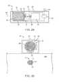
- FIG. 2Aillustrates an external adjustment device according to one embodiment.
- the external adjustment deviceincludes a single permanent magnet configured for rotational movement.
- FIG. 2Bis a side view of the external adjustment device of FIG. 2A .
- FIG. 2Cillustrates an external adjustment device according to one embodiment.
- the external adjustment deviceincludes a single electromagnet configured to generate a rotating magnetic field.
- FIG. 2Dis a side view of the external adjustment device of FIG. 2C .
- FIG. 3illustrates a magnet assembly containing a permanent magnet therein.
- An induction coilis disposed adjacent to the magnet assembly.
- FIG. 4is graph of the signal captured by the induction coil on the external adjustment device of FIGS. 2A and 2B .
- the induction coilwas a forty (40) turn coil.
- the illustrated signalis amplified 100 ⁇ .
- FIG. 5is a graph of the perturbation or twitch signal superimposed on the signal of the external adjustment device captured by the induction coil.
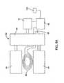
- FIG. 6is a perturbation or twitch detection circuit for the external adjustment device of FIGS. 2A and 2B .
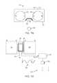
- FIG. 7Aillustrates a side view of an external adjustment device according to another embodiment.
- FIG. 7Billustrates a bottom view of the external adjustment device of FIG. 7A .
- FIG. 7Cillustrates a side view of an external adjustment device according to another embodiment.
- FIG. 7Dillustrates a bottom view of the external adjustment device of FIG. 7C .
- FIG. 8schematically represents a two magnet external adjustment device.
- FIG. 8Aschematically represents an external adjustment device having two electromagnets.
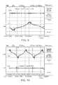
- FIG. 9is a graph of the signal of a two magnet external adjustment device captured by an induction coil.
- the induction coilis a coil having 20 turns and the signal is amplified 23 ⁇ .
- FIG. 10is a graph of the perturbation or twitch signal superimposed on the signal (complete waveform) of a two magnet external adjustment device captured by the induction coil.
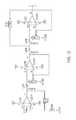
- FIG. 11is a schematic of a 3rd order Bessel filter circuit (fc ⁇ 200 Hz) used to form an active filter network.
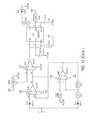
- FIG. 12is a schematic of a circuit for twitch detection for the dual magnet embodiment of FIGS. 7A and 7B with a visual alert indicator.
- FIG. 1illustrates an implantable medical device 10 according to one embodiment.
- the implantable medical device 10may include a distraction device such as an expandable or growing rod that is implanted inside the body although other implantable medical devices 10 that change in length and/or force are also contemplated.
- the implantable medical device 10may be used in various anatomical spaces, for example, including along the spine or within or across other bones of the body.
- the implantable medical device 10includes a housing 12 and a telescoping rod 14 that moves in a telescoping fashion into and out of the housing 12 in the direction of arrow A.
- the housing 12includes a first end 16 that can be secured directly to the anatomical structure using any number of fasteners known to those skilled in the art such as screws, hooks, adhesives, and the like. Likewise, the distal end 15 of the rod 14 can be secured in a similar manner.
- a second end 18 of the housingincludes a recessed portion 20 in which the telescoping rod 14 is permitted to move in a telescoping fashion.
- Located inside the housing 12is a magnetic assembly 22 that is rotationally mounted therein using, for example, respective bearings 24 , 26 .
- the magnetic assembly 22includes a permanent magnet 28 contained therein.
- the permanent magnet 28may include, for example, a rare earth magnet formed from, for instance, Neodymium-Iron-Boron.
- the magnetmay be made from a grade of N35 or higher, for example a grade of N50.
- the magnetic assembly 22is secured at one end thereof to a screw 30 that extends longitudinally through the recess 20 of the housing 12 and interfaces with a nut 32 that is contained within the rod 14 .
- Rotation of the magnetic assembly 22results in corresponding rotation of the screw 30 which, due to the interface between the screw 30 and the nut 32 , results in telescopic movement of the rod 14 in the direction of arrow A.
- Rotational movement in one directionwill cause the implantable medical device 10 to lengthen (e.g., distraction) while rotational movement in a second, opposing direction will cause the implantable medical device 10 to shorten (e.g., compression). While FIG.
- FIG. 1illustrates one particular embodiment of an implantable medical device 10 it should be understood that the particular nature or construction of the implantable medical device 10 may vary considerably.
- the devices and methods contemplated hereinwork with any implantable medical device 10 that contains a magnet that is configured for rotation in response to an externally applied moving magnetic field.
- FIGS. 2A and 2Billustrate one embodiment of an external adjustment device 40 according to one embodiment.
- the external adjustment device 40is used to rotate the magnetic assembly 22 disposed within the implantable medical device 10 .
- the external adjustment device 40is illustrated as including a housing 42 that contains the various components into an integrated unit.
- a motor 44is disposed within the housing 42 and includes an output shaft 46 .
- the output shaft 46is connected though optional gear(s) 48 to an output shaft 50 .
- the output shaft 50may turn at different rotational speeds as compared to the output shaft 46 of the motor 44 .
- the gear(s) 48are optional and it may be possible that no intervening gears are used.
- the output shaft 46is coupled to a magnet assembly 52 .
- the magnet assembly 52includes a permanent magnet 54 that is rotationally mounted within a stationary outer housing 56 .
- the outer housing 56thus remains stationary while the permanent magnet 54 located therein is able to rotate about a rotational axis 58 (e.g., in the direction of arrow B).
- the magnet assembly 52includes an electromagnet 55 (rather than a permanent magnet 54 ) to create a rotating magnetic field.
- an induction coil 60is disposed on the outer housing 56 holding the permanent magnet 54 .
- the induction coil 60may include a wire or other conductor.
- the induction coil 60is a coiled wire.
- the changing magnetic field between the magnetically coupled permanent magnet 28 of the internally-disposed magnetic assembly 22 and the rotating permanent magnet 54 of the external adjustment device 40induces a current in the induction coil 60 that is proportional to the rate of change of the magnetic field. More specifically, the induced current over the resistance of the induction coil 60 produces a voltage across the length of the conductor or wire that makes up the induction coil 60 . This voltage varies with the rate of change of the magnetic field surrounding the induction coil 60 . As explained below, the time-varying voltage is the signal that can be monitored to detect slippage between the permanent magnet 28 of the implantable medical device 10 and the permanent magnet 54 of the external adjustment device 40 .
- the external adjustment device 40includes circuitry 62 (e.g., detection circuitry) that is used to monitor the time varying voltage signal in the induction coil 60 .
- This same circuitry 62may also be used, optionally, to control the motor 44 .
- the circuitry 62may interface with inputs 66 , 68 (e.g., buttons) that drive the motor 44 in opposing directions.
- the circuitry 62may receive instructions input from the user on the desired degree of change of length of the implantable medical device 10 (e.g., distract 1 mm)
- the circuitry 62may be integrated into one or more processors or the like that is located within the external adjustment device 40 .
- the electronics for the circuitry 62 and the motor 44may be supplied using a cable the plugs into a standard A/C wall outlet or it may be powered by one or more batteries contained in the external adjustment device 40 .
- the circuitry 62is used to detect slippage of magnetic coupling between the permanent magnet 28 of the implantable device 10 and the permanent magnet 54 of the external adjustment device 40 .
- the circuitry 62monitors the time varying voltage signal from the induction coil 60 and looks for perturbations in this signal. Perturbations or “twitches” of the voltage signal are, as explained below, are indicative that slippage between the permanent magnet 28 of the implantable device 10 and the permanent magnet 54 of the external adjustment device 40 .
- the permanent magnet 28 of the implantable device 10will also rotate provided that the permanent magnet 28 of the implantable device 10 is not restricted from rotational movement.
- the permanent magnet 28 of the implantable device 10is restricted from movement and the permanent magnet 54 of the external adjustment device 40 rotates, one can define a “lagging angle” as the angle through which the permanent magnet 28 of the implantable device 10 would have rotated but for the restriction.
- the permanent magnet 28 of the implantable device 10accelerates and then decelerates through this lagging angle and results in a “twitch.”
- the twitchis detected by the circuitry 62 which indicates slippage between the two respective magnetic fields.
- rotating the permanent magnet 28 in the distraction directionincreases the torque required to rotate it further in that direction.
- rotating the permanent magnet 28 in the retraction directionreduces the torque required to then rotate it in the distraction direction (assuming device is not in tension yet). If the permanent magnet 28 stalls during distraction, when the lagging angle reaches 180° the permanent magnet 28 will reverse direction and twitch until the fields align, distraction torque is applied, and the permanent magnet 28 again rotates in the distraction direction with increasing torque as the lagging angle increases.
- the magnetic field orientations of the coupled magnets 28 , 54rotate through a cycle.
- the cyclerepeats with every rotation of the permanent magnet 54 of the external adjustment device 40 .
- the scalar amount of torque imparted by the coupled fields on the permanent magnet 28rises and falls on the same cycle. If at some point the permanent magnet 28 stalls, the permanent magnet 28 will twitch with every subsequent magnet 54 rotation cycle until the distraction force is lowered.
- the changing magnetic field or perturbation caused by the twitchis sensed by the induction coil 60 .
- the changing magnetic fieldinduces a current in the conductor or wire of the induction coil 60 .
- a 90° rotation of the permanent magnet 28 over 6 millisecondsproduces a change in the coupled magnetic field large enough to be detected with the required discretion to be a reliable indication of stalled distraction.
- the induced current over the resistance in the conductor or wire of the induction coil 60produces a voltage potential across the length of conductor or wire in the induction coil 60 . This voltage varies with the rate of change of the magnetic field surrounding the induction coil 60 . It is this time varying voltage that is the signal from which the twitch can be identified.
- the external adjustment device 40includes an indicator 70 that is operatively coupled to circuitry 62 .
- the indicator 70alerts the user of the external adjustment device 40 to slippage of magnetic coupling.
- This indictor 70may include a visual indicator such as illumination of a light or LED.
- the indicator 70may also include an audible indicator that emits a tone or other sound to indicate slippage.
- the indicator 70may include a tactile indicator that vibrates or otherwise causes movement that may be sensed by the user holding the external adjustment device 40 .
- a piezoelectric-based vibrating elementmay, for example, be used.
- FIG. 3illustrates the magnet assembly 52 of the external adjustment device 40 with an oval-shaped induction coil 60 in the shape of a coil.
- the induction coil 60may be mounted on the surface of the magnet assembly 52 or it can be mounted elsewhere in or on the external adjustment device 40 such that the induction coil 60 is interposed and stationary between the permanent magnet 28 of the implantable medical device 10 and the permanent magnet 54 of the external adjustment device 40 .
- the induction coil 60does not need to lie in a plane between the permanent magnet 28 and the permanent magnet 54 of the external adjustment device 40 .
- the induction coil 60may, for example, be laterally offset from a plane or line connecting permanent magnet 28 to permanent magnet 54 .
- the induction coil 60does not have to be coil-shaped as any shape will respond to changes in the magnetic field.
- the external adjustment device 40is brought in close proximity to the subject 200 as seen in FIG. 2B whereby the permanent magnet 54 of the external adjustment device 40 is actuated.
- the rotational speed of the permanent magnet 54 of the external adjustment device 40may vary but it is generally around 30 rpm (a period of 0.5 Hz).
- Rotation of the magnetic field of the permanent magnet 54 of the magnet assembly 52induces a time varying voltage across the induction coil 60 that approximates a sinusoid.
- a one inch diameter, 40 turn coiled induction coil 60which is reoriented into the shape shown in in FIG. 3 produces a 10 mV peak to peak cyclic signal when mounted 4 mm from the surface of a two inch diameter ⁇ 1.5′′ long permanent magnet 54 as seen in FIG.
- Different permanent magnets 54(different in dimension or bulk magnetization) would induce different signals in the induction coil 60 (both shape and amplitude) depending on the change in the strength and direction of the magnetic field vector acting on the induction coil 60 as the permanent magnet 54 rotates.
- FIG. 5illustrates a similar sinusoidal signal obtained from an induction coil 60 interposed between a rotating permanent magnet 54 and a permanent magnet 28 of the implantable medical device 10 .
- the permanent magnet 28is stalled and a twitch signal is produced and captured by the induction coil 60 .
- the twitch signalsare shown superimposed on the sinusoidal signal of the rotating permanent magnet 54 in FIG. 5 .
- the shape and amplitude of the twitcheswill vary depending on the relative alignment of the fields at the time of the stall.
- the frequency of the twitch signalis between about 150 Hz and about 200 Hz (e.g., ⁇ 170 Hz) which is high enough relative to the signal produced by the magnet of the permanent magnet 54 of the external adjustment device 40 such that it can be separated by passive networks, rectified, and normalized using a comparator as part of circuitry 62 .
- the resultant signalcan be used to trigger an alert to the user via indicator 70 as notification that the stall has been detected.
- detection of one or more twitchesmay automatically prevent additional rotations of the permanent magnet 54 of the external adjustment device 40 , for example by control circuitry stopping a motor that control rotation of the permanent magnet 54 .
- FIG. 6A circuit suitable to accomplish this detection is shown in FIG. 6 .
- Op-amp U 1 Aprovides an initial voltage gain of 100.
- Capacitor CP 1 and resistor R 3form a passive high pass filter with a 3 db cut off frequency of ⁇ 15 Hz. This removes the 0.5 Hz sinusoidal component (generated by external adjustment device 40 ) from the waveform.
- Op-amps U 1 B and U 1 C(with diodes D 1 and D 2 ) rectify the waveform such that all voltages are positive.
- FIG. 5shows that there are instances when the highest angular velocity of the twitch is in the direction that produces a negative potential. Rectifying the waveform ensures that the largest angular velocity component of the twitch is utilized in the detection.
- Op-amp U 1 Dis a comparator whose reference is set by variable resistor RV 1 .
- the referenceis set at ⁇ 2 ⁇ the amplitude of noise in the waveform. This eliminates false positive trigger events.
- the output of op-amp U 1 Dis the positive rail voltage for the duration that the twitch potential is above the reference.
- the output of op-amp U 1 Dprovides the trigger pulse to integrated circuit U 2 , a 555 timer configured as a mono-stable tank circuit. Timing components capacitor C 3 and resistor R 8 determine that the light emitting diode LED D 3 will light for ⁇ 0.3 seconds when a trigger pulse is sensed.
- FIGS. 7A, 7B, 7C, 7D, 8, and 8Aillustrate alternative embodiments of an external adjustment device 80 .
- This external adjustment device 80is different from the external adjustment device of FIGS. 2A, 2B, 2C, and 2D in that there are two (2) permanent magnets 82 , 84 , or electromagnets 83 , 85 , whose magnetic fields, or, in the case of electromagnets 83 and 85 , the magnetic fields they create, are aligned and rotate in synchronization.
- the two (2) permanent magnets are 82 , 84are positioned close enough such that their respective magnetic fields cycle through attraction and repulsion. As seen in FIG.
- both permanent magnets 82 , 84are driven using a motor 86 that couples to each permanent magnet 82 , 84 via gearing 88 .
- Examples of external adjustment devices having two permanent magnets and usable in connection with the devices and methods disclosed hereininclude those disclosed in U.S. Pat. No. 7,862,502, U.S. Patent Application Nos. 2010-0217271 and 2012-0004494, which are incorporated herein by reference.
- An induction coil 90is disposed between each permanent magnet 82 , 84 .
- the induction coil 90may include a coil, loop, or other structure as described herein and may be mounted on or within a housing 92 forming the external adjustment device 80 . As best seen in FIG. 7A , the induction coil 90 may have an arcuate shape that conforms to the recess 94 formed in the housing 92 between permanent magnets 82 , 84 .
- the induction coil 90is coupled to ground 96 at one end (as seen in FIGS. 7B and 8 ) while the opposing end of the induction coil is coupled to circuitry 98 where the time varying voltage signal is monitored as explained herein.
- the circuitry 98may also optionally interface with the motor 86 so as to control the rotation of the permanent magnets 82 , 84 .
- the circuitry 98is connected to an indicator 100 that is similar to the indicator 70 described with the respect to the prior embodiment.
- the indicator 100may alert a user of the external adjustment device 80 to slippage of the permanent magnet 28 of the implantable device 10 using a visual, auditory, or tactile/haptic signal.
- FIG. 7Billustrates the oscillating raw signal 102 received by the induction coil 90 . This signal 102 is then processed and monitored by circuitry 98 in which the higher frequency twitches are passed and rectified (seen as signal 104 ) which is used to trigger an alert at indicator 100 .
- the permanent magnets 82 , 84 of the external adjustment device 80are connected with gearing 88 (e.g., multiple gears) that have some level of lash. This allows for the production of an external adjustment device 80 twitch in the same way that the permanent magnet 28 of the implantable medical device 10 (i.e., driven magnet) twitches are produced, however, these may be removed by the circuitry 98 during processing of the signal. Additionally, the strong magnetic coupling of the permanent magnets 82 , 84 of the external adjustment device 80 adds higher order components to the base external adjustment device 80 waveform produced by the induction coil 90 (as seen in FIG. 9 ). The lower trace in FIG.
- C(t)shows the signal from a 20 turn, one inch diameter pickup coil induction coil 90 mounted to a dual magnet external adjustment device 80 as shown in FIGS. 7A and 7B .
- the higher frequency componentsare the magnet twitch of the external adjustment device 80 .
- the wavelength of these componentswas measured to be ⁇ 50 Hz—100 ⁇ the frequency of the single magnet external adjustment device 40 from the embodiment illustrated in FIGS. 2A and 2B .
- the complete waveform with the driven magnet twitchis illustrated in the upper trace FIG. 10 .
- the circuitry 98includes an active filter network that is used to separate the ⁇ 150-200 Hz twitch signal from the driven magnet 28 from the base waveform produced by the external adjustment device 80 so that the twitch of the permanent magnet 28 of the implantable medical device 10 is not masked by the twitch caused by the attraction of the permanent magnets 82 , 84 of the external adjustment device 80 to each other.
- a third order Bessel filterwas developed for this purpose and is illustrated in FIG. 11 .
- the circuit componentsinclude op-amps U 2 B, U 2 C; resistors R 12 , R 13 , R 14 ; and capacitors CP 4 , CP 5 , and CP 6 .
- the frequency response of the filterwas measured at the two (2) points of interest as shown below in Table 1.
- the filtered waveformis shown as the lower trace in FIG. 10 .
- This waveformcan be rectified and normalized using a comparator as in the embodiment of FIGS. 2A and 2B .
- the resultant signalcan be used to trigger an alert indicator 100 as notification that the stall has been detected.
- Circuitry 98 suitable to accomplish this detectionis shown in FIG. 12 .
- Op-amp U 3 Aprovides an initial voltage gain of 23.
- Capacitor CP 7 and resistor R 17 and op-amps U 3 B and U 3 Cform the active filter of FIG. 11 . This removes the ⁇ 50 Hz components of the external adjustment device 80 from the waveform.
- Op-amps U 3 D and U 3 Erectify the waveform such that all voltages are positive.
- FIG. 10shows that there are instances when the highest angular velocity of the twitch is in the direction that produces a negative potential. Rectifying the waveform ensures that the largest angular velocity component of the twitch is utilized in the detection.
- Op-amp U 3 Fis a comparator whose reference is set by variable resistor RV 2 . The reference is set at ⁇ 2 ⁇ the amplitude of noise in the waveform. This eliminates false positive trigger events.
- the output of op-amp U 3 Fis the positive rail voltage for the duration that the twitch potential is above the reference.
- op-amp U 3 Fprovides the trigger pulse to integrated circuit U 3 , a 555 timer configured as a mono-stable tank circuit.
- Timing componentsincluding capacitor CP 10 and resistor R 25 determine that the LED D 6 will lite for ⁇ 0.3 seconds when a trigger pulse is sensed.
Landscapes
- Health & Medical Sciences (AREA)
- Life Sciences & Earth Sciences (AREA)
- Engineering & Computer Science (AREA)
- Surgery (AREA)
- Orthopedic Medicine & Surgery (AREA)
- Physics & Mathematics (AREA)
- Veterinary Medicine (AREA)
- Heart & Thoracic Surgery (AREA)
- Medical Informatics (AREA)
- Molecular Biology (AREA)
- Biomedical Technology (AREA)
- Animal Behavior & Ethology (AREA)
- General Health & Medical Sciences (AREA)
- Public Health (AREA)
- Neurology (AREA)
- Pathology (AREA)
- Biophysics (AREA)
- Power Engineering (AREA)
- Electromagnetism (AREA)
- Nuclear Medicine, Radiotherapy & Molecular Imaging (AREA)
- Physiology (AREA)
- Human Computer Interaction (AREA)
- Transplantation (AREA)
- Artificial Intelligence (AREA)
- Computer Vision & Pattern Recognition (AREA)
- Psychiatry (AREA)
- Signal Processing (AREA)
- Prostheses (AREA)
- Magnetic Treatment Devices (AREA)
- Magnetic Resonance Imaging Apparatus (AREA)
Abstract
Description
| TABLE 1 | |||
| Frequency [=] Hz | Output V [=] | ||
| 50 | 0.26 | ||
| 170 | 2.64 | ||
Claims (23)
Priority Applications (1)
| Application Number | Priority Date | Filing Date | Title |
|---|---|---|---|
| US14/737,192US9730612B2 (en) | 2012-06-06 | 2015-06-11 | Devices and methods for detection of slippage of magnetic coupling in implantable medical devices |
Applications Claiming Priority (2)
| Application Number | Priority Date | Filing Date | Title |
|---|---|---|---|
| US13/490,107US9078711B2 (en) | 2012-06-06 | 2012-06-06 | Devices and methods for detection of slippage of magnetic coupling in implantable medical devices |
| US14/737,192US9730612B2 (en) | 2012-06-06 | 2015-06-11 | Devices and methods for detection of slippage of magnetic coupling in implantable medical devices |
Related Parent Applications (1)
| Application Number | Title | Priority Date | Filing Date |
|---|---|---|---|
| US13/490,107ContinuationUS9078711B2 (en) | 2012-06-06 | 2012-06-06 | Devices and methods for detection of slippage of magnetic coupling in implantable medical devices |
Publications (2)
| Publication Number | Publication Date |
|---|---|
| US20150272471A1 US20150272471A1 (en) | 2015-10-01 |
| US9730612B2true US9730612B2 (en) | 2017-08-15 |
Family
ID=49712561
Family Applications (2)
| Application Number | Title | Priority Date | Filing Date |
|---|---|---|---|
| US13/490,107Active2033-04-12US9078711B2 (en) | 2012-06-06 | 2012-06-06 | Devices and methods for detection of slippage of magnetic coupling in implantable medical devices |
| US14/737,192ActiveUS9730612B2 (en) | 2012-06-06 | 2015-06-11 | Devices and methods for detection of slippage of magnetic coupling in implantable medical devices |
Family Applications Before (1)
| Application Number | Title | Priority Date | Filing Date |
|---|---|---|---|
| US13/490,107Active2033-04-12US9078711B2 (en) | 2012-06-06 | 2012-06-06 | Devices and methods for detection of slippage of magnetic coupling in implantable medical devices |
Country Status (3)
| Country | Link |
|---|---|
| US (2) | US9078711B2 (en) |
| DE (1) | DE112013002825B4 (en) |
| WO (1) | WO2013184717A1 (en) |
Cited By (3)
| Publication number | Priority date | Publication date | Assignee | Title |
|---|---|---|---|---|
| US20230041121A1 (en)* | 2021-08-03 | 2023-02-09 | Nuvasive Specialized Orthopedics, Inc. | Adjustable implant |
| US20230248398A1 (en)* | 2009-04-29 | 2023-08-10 | Nuvasive Specialized Orthopedics, Inc. | Interspinous process device and method |
| US12433649B2 (en) | 2019-02-13 | 2025-10-07 | The Trustees Of The University Of Pennsylvania | Systems and methods for a smart, implantable cranio-maxillo-facial distractor |
Families Citing this family (17)
| Publication number | Priority date | Publication date | Assignee | Title |
|---|---|---|---|---|
| AU2009310439B2 (en)* | 2008-10-31 | 2016-05-26 | Implantica Patent Ltd. | Device and method for bone adjustment with anchoring function |
| US9078711B2 (en) | 2012-06-06 | 2015-07-14 | Ellipse Technologies, Inc. | Devices and methods for detection of slippage of magnetic coupling in implantable medical devices |
| US10551215B2 (en)* | 2015-06-11 | 2020-02-04 | Analog Devices Global Unlimited Company | Systems, circuits and methods for determining a position of a movable object |
| US12262917B2 (en) | 2016-05-19 | 2025-04-01 | Auctus Surgical, Inc. | Spinal curvature modulation systems and methods |
| CN109152596B (en) | 2016-05-19 | 2022-07-08 | 奥图斯外科手术股份有限公司 | Spinal curvature adjustment system |
| US10893369B2 (en) | 2017-06-02 | 2021-01-12 | Cochlear Limited | Controlled fitting of an implantable medical device |
| US11589901B2 (en)* | 2019-02-08 | 2023-02-28 | Nuvasive Specialized Orthopedics, Inc. | External adjustment device |
| CA3139557A1 (en) | 2019-06-11 | 2020-12-17 | Yves Moser | External actuation device for adjustable implanted medical device |
| WO2022015898A1 (en) | 2020-07-17 | 2022-01-20 | Nuvasive Specialized Orthopedics, Inc. | Extramedullary device and system |
| US20220265326A1 (en) | 2021-02-23 | 2022-08-25 | Nuvasive Specialized Orthopedics, Inc. | Adjustable implant, system and methods |
| US11737787B1 (en) | 2021-05-27 | 2023-08-29 | Nuvasive, Inc. | Bone elongating devices and methods of use |
| US20240358412A1 (en) | 2021-06-25 | 2024-10-31 | Nuvasive Specialized Orthopedics, Inc. | Adjustable implant, system and methods |
| US20230397935A1 (en) | 2022-06-13 | 2023-12-14 | Nuvasive Specialized Orthopedics, Inc. | Distraction loss magnet on-off mechanism |
| US20240050134A1 (en) | 2022-08-15 | 2024-02-15 | Nuvasive Specialized Orthopedics, Inc. | Intermedullary lengthening implant with integrated load sensor |
| US20240225704A9 (en) | 2022-10-21 | 2024-07-11 | Nuvasive Specialized Orthopedics, Inc. | Extramedullary device |
| US20240358418A1 (en) | 2023-04-25 | 2024-10-31 | Nuvasive Specialized Orthopedics, Inc. | Flat plate mechanisms for bone lengthening |
| US20240366273A1 (en) | 2023-05-03 | 2024-11-07 | Nuvasive Specialized Orthopedics, Inc. | Adjustable implant |
Citations (117)
| Publication number | Priority date | Publication date | Assignee | Title |
|---|---|---|---|---|
| US3512901A (en) | 1967-07-28 | 1970-05-19 | Carrier Corp | Magnetically coupled pump with slip detection means |
| US4973331A (en) | 1989-03-08 | 1990-11-27 | Autogenesis Corporation | Automatic compression-distraction-torsion method and apparatus |
| US5491407A (en)* | 1995-02-03 | 1996-02-13 | Kearney-National, Inc. | Wheel bearing speed sensor |
| US5626579A (en) | 1993-02-12 | 1997-05-06 | The Cleveland Clinic Foundation | Bone transport and lengthening system |
| US5672175A (en) | 1993-08-27 | 1997-09-30 | Martin; Jean Raymond | Dynamic implanted spinal orthosis and operative procedure for fitting |
| US5704939A (en) | 1996-04-09 | 1998-01-06 | Justin; Daniel F. | Intramedullary skeletal distractor and method |
| US5762599A (en) | 1994-05-02 | 1998-06-09 | Influence Medical Technologies, Ltd. | Magnetically-coupled implantable medical devices |
| US5961553A (en) | 1995-02-13 | 1999-10-05 | Medinov-Amp | Long bone elongation device |
| US6336929B1 (en) | 1998-01-05 | 2002-01-08 | Orthodyne, Inc. | Intramedullary skeletal distractor and method |
| US6375682B1 (en) | 2001-08-06 | 2002-04-23 | Lewis W. Fleischmann | Collapsible, rotatable and expandable spinal hydraulic prosthetic device |
| US6416516B1 (en) | 1999-02-16 | 2002-07-09 | Wittenstein Gmbh & Co. Kg | Active intramedullary nail for the distraction of bone parts |
| US6570375B2 (en)* | 2001-03-08 | 2003-05-27 | Daimlerchrysler Corporation | Wheel speed sensor with positive mounting latch |
| US6657351B2 (en) | 1998-02-10 | 2003-12-02 | Light Sciences Corporation | Contactless energy transfer apparatus |
| US6667725B1 (en) | 2002-08-20 | 2003-12-23 | The United States Of America As Represented By The Administrator Of The National Aeronautics And Space Administration | Radio frequency telemetry system for sensors and actuators |
| US20040023623A1 (en) | 2000-11-09 | 2004-02-05 | Roman Stauch | Device for controlling, regulating and/or putting an active implant into operation |
| US6706042B2 (en) | 2001-03-16 | 2004-03-16 | Finsbury (Development) Limited | Tissue distractor |
| US6796984B2 (en) | 2000-02-29 | 2004-09-28 | Soubeiran Andre Arnaud | Device for relative displacement of two bodies |
| US6835207B2 (en) | 1996-07-22 | 2004-12-28 | Fred Zacouto | Skeletal implant |
| US6849076B2 (en) | 2000-04-13 | 2005-02-01 | University College London | Surgical distraction device |
| US20050080427A1 (en) | 2002-07-18 | 2005-04-14 | Assaf Govari | Distal targeting of locking screws in intramedullary nails |
| US20050090823A1 (en) | 2003-10-28 | 2005-04-28 | Bartimus Christopher S. | Posterior fixation system |
| US20050159754A1 (en) | 2004-01-21 | 2005-07-21 | Odrich Ronald B. | Periosteal distraction bone growth |
| US20050234448A1 (en) | 2004-03-19 | 2005-10-20 | Mccarthy James | Implantable bone-lengthening device |
| US20050246020A1 (en) | 2004-04-30 | 2005-11-03 | Southworth Carleton B | Implant system with migration measurement capacity |
| US20050261779A1 (en) | 2003-11-17 | 2005-11-24 | Meyer Rudolf X | Expansible rod-type prosthesis and external magnetic apparatus |
| US20060036324A1 (en) | 2004-08-03 | 2006-02-16 | Dan Sachs | Adjustable spinal implant device and method |
| US20060036259A1 (en) | 2004-08-03 | 2006-02-16 | Carl Allen L | Spine treatment devices and methods |
| US20060032314A1 (en) | 2002-07-10 | 2006-02-16 | Hnat William P | Strain sensing system |
| US20060036323A1 (en) | 2004-08-03 | 2006-02-16 | Carl Alan L | Facet device and method |
| US7001346B2 (en) | 2001-11-14 | 2006-02-21 | Michael R. White | Apparatus and methods for making intraoperative orthopedic measurements |
| US20060052782A1 (en) | 2004-06-07 | 2006-03-09 | Chad Morgan | Orthopaedic implant with sensors |
| US20060069447A1 (en) | 2004-09-30 | 2006-03-30 | Disilvestro Mark R | Adjustable, remote-controllable orthopaedic prosthesis and associated method |
| US20060070451A1 (en) | 2004-09-24 | 2006-04-06 | University Of Louisville Research Foundation, Inc. | MEMS capacitive cantilever strain sensor, devices, and formation methods |
| US7063706B2 (en) | 2001-11-19 | 2006-06-20 | Wittenstein Ag | Distraction device |
| US20060136062A1 (en) | 2004-12-17 | 2006-06-22 | Dinello Alexandre | Height-and angle-adjustable motion disc implant |
| WO2006090380A2 (en) | 2005-02-22 | 2006-08-31 | Orthogon Technologies 2003 Ltd. | Device and method for vertebral column distraction and oscillation |
| WO2006103074A1 (en) | 2005-03-31 | 2006-10-05 | Covidien Ag | Connector for medical applications |
| US20060235424A1 (en) | 2005-04-01 | 2006-10-19 | Foster-Miller, Inc. | Implantable bone distraction device and method |
| US7135022B2 (en) | 2001-05-23 | 2006-11-14 | Orthogon 2003 Ltd. | Magnetically-actuable intramedullary device |
| US20060293683A1 (en) | 2003-04-16 | 2006-12-28 | Roman Stauch | Device for lengthening bones or bone parts |
| US20070010814A1 (en) | 2003-08-28 | 2007-01-11 | Roman Stauch | Device for extending bones |
| US20070179493A1 (en) | 2006-01-13 | 2007-08-02 | Kim Richard C | Magnetic spinal implant device |
| US20070264605A1 (en) | 2005-05-19 | 2007-11-15 | Theodore Belfor | System and method to bioengineer facial form in adults |
| US20070276378A1 (en) | 2004-09-29 | 2007-11-29 | The Regents Of The University Of California | Apparatus and methods for magnetic alteration of anatomical features |
| US20070276369A1 (en) | 2006-05-26 | 2007-11-29 | Sdgi Holdings, Inc. | In vivo-customizable implant |
| US20080033436A1 (en) | 2004-08-30 | 2008-02-07 | Vermillion Technologies, Llc | Device and method for treatment of spinal deformity |
| US7357635B2 (en) | 2004-05-19 | 2008-04-15 | Orthovisage Inc. | System and method to bioengineer facial form in adults |
| US20080097188A1 (en) | 2006-10-20 | 2008-04-24 | Ellipse Technologies, Inc. | External sensing systems and methods for gastric restriction devices |
| US20080097487A1 (en) | 2006-10-20 | 2008-04-24 | Scott Pool | Method and apparatus for adjusting a gastrointestinal restriction device |
| US20080097496A1 (en) | 2006-10-20 | 2008-04-24 | Arvin Chang | System and method for securing an implantable interface to a mammal |
| US20080161933A1 (en) | 2005-09-26 | 2008-07-03 | Innvotec Surgical, Inc. | Selectively expanding spine cage, hydraulically controllable in three dimensions for vertebral body replacement |
| US20080167685A1 (en) | 2007-01-05 | 2008-07-10 | Warsaw Orthopedic, Inc. | System and Method For Percutanously Curing An Implantable Device |
| US20080172072A1 (en) | 2007-01-11 | 2008-07-17 | Ellipse Technologies, Inc. | Internal sensors for use with gastric restriction devices |
| US20080228186A1 (en) | 2005-04-01 | 2008-09-18 | The Regents Of The University Of Colorado | Graft Fixation Device |
| US20080255615A1 (en) | 2007-03-27 | 2008-10-16 | Warsaw Orthopedic, Inc. | Treatments for Correcting Spinal Deformities |
| US7458981B2 (en) | 2004-03-09 | 2008-12-02 | The Board Of Trustees Of The Leland Stanford Junior University | Spinal implant and method for restricting spinal flexion |
| US20080300597A1 (en) | 2005-08-23 | 2008-12-04 | Smith & Nephew, Inc. | Telemetric Orthopaedic Implant |
| US20090076597A1 (en) | 2007-09-19 | 2009-03-19 | Jonathan Micheal Dahlgren | System for mechanical adjustment of medical implants |
| US20090093890A1 (en) | 2007-10-04 | 2009-04-09 | Daniel Gelbart | Precise control of orthopedic actuators |
| US20090112262A1 (en) | 2007-10-30 | 2009-04-30 | Scott Pool | Skeletal manipulation system |
| US7531002B2 (en) | 2004-04-16 | 2009-05-12 | Depuy Spine, Inc. | Intervertebral disc with monitoring and adjusting capabilities |
| US20090171356A1 (en) | 2008-01-02 | 2009-07-02 | International Business Machines Corporation | Bone Repositioning Apparatus and System |
| US20090192514A1 (en) | 2007-10-09 | 2009-07-30 | Feinberg Stephen E | Implantable distraction osteogenesis device and methods of using same |
| US7601156B2 (en) | 2001-12-05 | 2009-10-13 | Randolph C. Robinson | Limb lengthener |
| US7611526B2 (en) | 2004-08-03 | 2009-11-03 | K Spine, Inc. | Spinous process reinforcement device and method |
| US20090273353A1 (en) | 2003-09-16 | 2009-11-05 | Cardiomems | Strain monitoring system and apparatus |
| US7666184B2 (en) | 2003-08-28 | 2010-02-23 | Wittenstein Ag | Planetary roll system, in particular for a device for extending bones |
| US20100094302A1 (en) | 2008-10-13 | 2010-04-15 | Scott Pool | Spinal distraction system |
| US20100100185A1 (en) | 2008-10-22 | 2010-04-22 | Warsaw Orthopedic, Inc. | Intervertebral Disc Prosthesis Having Viscoelastic Properties |
| US7776091B2 (en) | 2004-06-30 | 2010-08-17 | Depuy Spine, Inc. | Adjustable posterior spinal column positioner |
| US20100217271A1 (en) | 2009-02-23 | 2010-08-26 | Ellipse Technologies, Inc. | Spinal distraction system |
| US20100228167A1 (en) | 2005-08-01 | 2010-09-09 | Mordechay Ilovich | Implantable Magnetically Activated Actuator |
| US7794476B2 (en) | 2003-08-08 | 2010-09-14 | Warsaw Orthopedic, Inc. | Implants formed of shape memory polymeric material for spinal fixation |
| US20100249847A1 (en) | 2006-06-29 | 2010-09-30 | Searete Llc, A Limited Liability Corporation Of The State Of Delaware | Position augmenting mechanism |
| US7811328B2 (en) | 2005-04-29 | 2010-10-12 | Warsaw Orthopedic, Inc. | System, device and methods for replacing the intervertebral disc with a magnetic or electromagnetic prosthesis |
| US20100262239A1 (en) | 2009-04-14 | 2010-10-14 | Searete Llc, A Limited Liability Corporation Of The State Delaware | Adjustable orthopedic implant and method for treating an orthopedic condition in a subject |
| US20100274114A1 (en) | 2007-06-07 | 2010-10-28 | Denker Stephen T | Signal sensing in an implanted apparatus with an internal reference |
| US20110004076A1 (en) | 2008-02-01 | 2011-01-06 | Smith & Nephew, Inc. | System and method for communicating with an implant |
| US7887566B2 (en) | 2004-09-16 | 2011-02-15 | Hynes Richard A | Intervertebral support device with bias adjustment and related methods |
| US20110152725A1 (en) | 2008-09-02 | 2011-06-23 | Christian M. Puttlitz Consulting, Llc | Biomems sensor and apparatuses and methods therefor |
| US20110257655A1 (en) | 2008-10-02 | 2011-10-20 | Copf Jr Franz | Instrument for measuring the distraction pressure between vertebral bodies |
| US8043299B2 (en) | 2006-11-06 | 2011-10-25 | Janet Conway | Internal bone transport |
| US20120004494A1 (en) | 2010-06-30 | 2012-01-05 | Timothy John Payne | External adjustment device for distraction device |
| US20120053633A1 (en) | 2010-08-26 | 2012-03-01 | Wittenstein Ag | Actuator for correcting scoliosis |
| US8147549B2 (en) | 2008-11-24 | 2012-04-03 | Warsaw Orthopedic, Inc. | Orthopedic implant with sensor communications antenna and associated diagnostics measuring, monitoring, and response system |
| US8147517B2 (en) | 2006-05-23 | 2012-04-03 | Warsaw Orthopedic, Inc. | Systems and methods for adjusting properties of a spinal implant |
| US20120088953A1 (en) | 2010-10-08 | 2012-04-12 | Jerry King | Fractured Bone Treatment Methods And Fractured Bone Treatment Assemblies |
| US20120109207A1 (en) | 2010-10-29 | 2012-05-03 | Warsaw Orthopedic, Inc. | Enhanced Interfacial Conformance for a Composite Rod for Spinal Implant Systems with Higher Modulus Core and Lower Modulus Polymeric Sleeve |
| US8177789B2 (en) | 2007-10-01 | 2012-05-15 | The General Hospital Corporation | Distraction osteogenesis methods and devices |
| US20120136229A1 (en) | 2004-07-08 | 2012-05-31 | Deborah Schenberger | Strain monitoring system and apparatus |
| US8221420B2 (en) | 2009-02-16 | 2012-07-17 | Aoi Medical, Inc. | Trauma nail accumulator |
| US20120203282A1 (en) | 2007-06-06 | 2012-08-09 | K Spine, Inc. | Medical device and method to correct deformity |
| US8241331B2 (en) | 2007-11-08 | 2012-08-14 | Spine21 Ltd. | Spinal implant having a post-operative adjustable dimension |
| US8252063B2 (en) | 2009-03-04 | 2012-08-28 | Wittenstein Ag | Growing prosthesis |
| US20120232834A1 (en) | 2005-11-28 | 2012-09-13 | Orthosensor, Inc. | Method and system for assessing orthopedic alignment using tracking sensors |
| US8282671B2 (en) | 2010-10-25 | 2012-10-09 | Orthonex | Smart device for non-invasive skeletal adjustment |
| US8298240B2 (en) | 2006-04-06 | 2012-10-30 | Synthes (Usa) | Remotely adjustable tissue displacement device |
| US20120283781A1 (en) | 2009-11-25 | 2012-11-08 | Uri Arnin | Spinal rod having a post-operative adjustable dimension |
| US8469908B2 (en) | 2007-04-06 | 2013-06-25 | Wilson T. Asfora | Analgesic implant device and system |
| WO2013119528A1 (en) | 2012-02-07 | 2013-08-15 | Io Surgical, Llc | Sensor system, implantable sensor and method for remote sensing of a stimulus in vivo |
| US8529606B2 (en) | 2009-03-10 | 2013-09-10 | Simpirica Spine, Inc. | Surgical tether apparatus and methods of use |
| US20130253344A1 (en) | 2012-03-26 | 2013-09-26 | Medtronic, Inc. | Intravascular implantable medical device introduction |
| US8562653B2 (en) | 2009-03-10 | 2013-10-22 | Simpirica Spine, Inc. | Surgical tether apparatus and methods of use |
| US8568457B2 (en) | 2009-12-01 | 2013-10-29 | DePuy Synthes Products, LLC | Non-fusion scoliosis expandable spinal rod |
| US20130296940A1 (en) | 2012-04-17 | 2013-11-07 | Aurora Spine, Llc | Dynamic and non-dynamic interspinous fusion implant and bone growth stimulation system |
| US20140005788A1 (en) | 2010-05-24 | 2014-01-02 | Aalto University Foundation | Implantable treatment device fixed or interlinked to bone |
| US8632544B2 (en) | 2008-03-19 | 2014-01-21 | Synoste Oy | Internal osteodistraction device |
| US8641723B2 (en) | 2010-06-03 | 2014-02-04 | Orthonex LLC | Skeletal adjustment device |
| US8663285B2 (en) | 2009-09-03 | 2014-03-04 | Dalmatic Lystrup A/S | Expansion devices |
| US8777947B2 (en) | 2010-03-19 | 2014-07-15 | Smith & Nephew, Inc. | Telescoping IM nail and actuating mechanism |
| US20140236311A1 (en) | 2011-06-27 | 2014-08-21 | University Of Cape Town | Endoprosthesis |
| US20140296918A1 (en) | 2011-12-12 | 2014-10-02 | Stephen D. Fening | Noninvasive device for adjusting fastener |
| US8870959B2 (en) | 2009-11-24 | 2014-10-28 | Spine21 Ltd. | Spinal fusion cage having post-operative adjustable dimensions |
| US8961567B2 (en) | 2010-11-22 | 2015-02-24 | DePuy Synthes Products, LLC | Non-fusion scoliosis expandable spinal rod |
| US8992527B2 (en) | 2009-06-24 | 2015-03-31 | Jean-Marc Guichet | Elongation nail for long bone or similar |
| US20150105824A1 (en) | 2005-04-12 | 2015-04-16 | Nathan C. Moskowitz | Bi-directional fixating transvertebral body screws, zero-profile horizontal intervertebral miniplates, total intervertebral body fusion devices, and posterior motion-calibrating interarticulating joint stapling device for spinal fusion |
| US9078711B2 (en) | 2012-06-06 | 2015-07-14 | Ellipse Technologies, Inc. | Devices and methods for detection of slippage of magnetic coupling in implantable medical devices |
- 2012
- 2012-06-06USUS13/490,107patent/US9078711B2/enactiveActive
- 2013
- 2013-06-04WOPCT/US2013/044168patent/WO2013184717A1/enactiveApplication Filing
- 2013-06-04DEDE112013002825.5Tpatent/DE112013002825B4/enactiveActive
- 2015
- 2015-06-11USUS14/737,192patent/US9730612B2/enactiveActive
Patent Citations (135)
| Publication number | Priority date | Publication date | Assignee | Title |
|---|---|---|---|---|
| US3512901A (en) | 1967-07-28 | 1970-05-19 | Carrier Corp | Magnetically coupled pump with slip detection means |
| US4973331A (en) | 1989-03-08 | 1990-11-27 | Autogenesis Corporation | Automatic compression-distraction-torsion method and apparatus |
| US5626579A (en) | 1993-02-12 | 1997-05-06 | The Cleveland Clinic Foundation | Bone transport and lengthening system |
| US5672175A (en) | 1993-08-27 | 1997-09-30 | Martin; Jean Raymond | Dynamic implanted spinal orthosis and operative procedure for fitting |
| US5762599A (en) | 1994-05-02 | 1998-06-09 | Influence Medical Technologies, Ltd. | Magnetically-coupled implantable medical devices |
| US5491407A (en)* | 1995-02-03 | 1996-02-13 | Kearney-National, Inc. | Wheel bearing speed sensor |
| US5961553A (en) | 1995-02-13 | 1999-10-05 | Medinov-Amp | Long bone elongation device |
| US5704939A (en) | 1996-04-09 | 1998-01-06 | Justin; Daniel F. | Intramedullary skeletal distractor and method |
| US6835207B2 (en) | 1996-07-22 | 2004-12-28 | Fred Zacouto | Skeletal implant |
| US20050055025A1 (en) | 1996-07-22 | 2005-03-10 | Fred Zacouto | Skeletal implant |
| US6336929B1 (en) | 1998-01-05 | 2002-01-08 | Orthodyne, Inc. | Intramedullary skeletal distractor and method |
| US6657351B2 (en) | 1998-02-10 | 2003-12-02 | Light Sciences Corporation | Contactless energy transfer apparatus |
| US6416516B1 (en) | 1999-02-16 | 2002-07-09 | Wittenstein Gmbh & Co. Kg | Active intramedullary nail for the distraction of bone parts |
| US6796984B2 (en) | 2000-02-29 | 2004-09-28 | Soubeiran Andre Arnaud | Device for relative displacement of two bodies |
| US6849076B2 (en) | 2000-04-13 | 2005-02-01 | University College London | Surgical distraction device |
| US20040023623A1 (en) | 2000-11-09 | 2004-02-05 | Roman Stauch | Device for controlling, regulating and/or putting an active implant into operation |
| US6570375B2 (en)* | 2001-03-08 | 2003-05-27 | Daimlerchrysler Corporation | Wheel speed sensor with positive mounting latch |
| US6706042B2 (en) | 2001-03-16 | 2004-03-16 | Finsbury (Development) Limited | Tissue distractor |
| US7135022B2 (en) | 2001-05-23 | 2006-11-14 | Orthogon 2003 Ltd. | Magnetically-actuable intramedullary device |
| US6375682B1 (en) | 2001-08-06 | 2002-04-23 | Lewis W. Fleischmann | Collapsible, rotatable and expandable spinal hydraulic prosthetic device |
| US7001346B2 (en) | 2001-11-14 | 2006-02-21 | Michael R. White | Apparatus and methods for making intraoperative orthopedic measurements |
| US7063706B2 (en) | 2001-11-19 | 2006-06-20 | Wittenstein Ag | Distraction device |
| US7601156B2 (en) | 2001-12-05 | 2009-10-13 | Randolph C. Robinson | Limb lengthener |
| US20060032314A1 (en) | 2002-07-10 | 2006-02-16 | Hnat William P | Strain sensing system |
| US20050080427A1 (en) | 2002-07-18 | 2005-04-14 | Assaf Govari | Distal targeting of locking screws in intramedullary nails |
| US6667725B1 (en) | 2002-08-20 | 2003-12-23 | The United States Of America As Represented By The Administrator Of The National Aeronautics And Space Administration | Radio frequency telemetry system for sensors and actuators |
| US20060293683A1 (en) | 2003-04-16 | 2006-12-28 | Roman Stauch | Device for lengthening bones or bone parts |
| US7794476B2 (en) | 2003-08-08 | 2010-09-14 | Warsaw Orthopedic, Inc. | Implants formed of shape memory polymeric material for spinal fixation |
| US20070010814A1 (en) | 2003-08-28 | 2007-01-11 | Roman Stauch | Device for extending bones |
| US7666184B2 (en) | 2003-08-28 | 2010-02-23 | Wittenstein Ag | Planetary roll system, in particular for a device for extending bones |
| US20090273353A1 (en) | 2003-09-16 | 2009-11-05 | Cardiomems | Strain monitoring system and apparatus |
| US20050090823A1 (en) | 2003-10-28 | 2005-04-28 | Bartimus Christopher S. | Posterior fixation system |
| US20050261779A1 (en) | 2003-11-17 | 2005-11-24 | Meyer Rudolf X | Expansible rod-type prosthesis and external magnetic apparatus |
| US20050159754A1 (en) | 2004-01-21 | 2005-07-21 | Odrich Ronald B. | Periosteal distraction bone growth |
| US8105363B2 (en) | 2004-03-09 | 2012-01-31 | The Board Of Trustees Of The Leland Stanford Junior University | Spinal implant and method for restricting spinal flexion |
| US8216275B2 (en) | 2004-03-09 | 2012-07-10 | The Board Of Trustees Of The Leland Stanford Junior University | Spinal implant and method for restricting spinal flexion |
| US8486110B2 (en) | 2004-03-09 | 2013-07-16 | The Board Of Trustees Of The Leland Stanford Junior University | Spinal implant and method for restricting spinal flexion |
| US7458981B2 (en) | 2004-03-09 | 2008-12-02 | The Board Of Trustees Of The Leland Stanford Junior University | Spinal implant and method for restricting spinal flexion |
| US20050234448A1 (en) | 2004-03-19 | 2005-10-20 | Mccarthy James | Implantable bone-lengthening device |
| US7531002B2 (en) | 2004-04-16 | 2009-05-12 | Depuy Spine, Inc. | Intervertebral disc with monitoring and adjusting capabilities |
| US20050246020A1 (en) | 2004-04-30 | 2005-11-03 | Southworth Carleton B | Implant system with migration measurement capacity |
| US7357635B2 (en) | 2004-05-19 | 2008-04-15 | Orthovisage Inc. | System and method to bioengineer facial form in adults |
| US20060052782A1 (en) | 2004-06-07 | 2006-03-09 | Chad Morgan | Orthopaedic implant with sensors |
| US7776091B2 (en) | 2004-06-30 | 2010-08-17 | Depuy Spine, Inc. | Adjustable posterior spinal column positioner |
| US20120136229A1 (en) | 2004-07-08 | 2012-05-31 | Deborah Schenberger | Strain monitoring system and apparatus |
| US20120136278A1 (en) | 2004-07-08 | 2012-05-31 | Deborah Schenberger | Strain monitoring system and apparatus |
| US20060036259A1 (en) | 2004-08-03 | 2006-02-16 | Carl Allen L | Spine treatment devices and methods |
| US20060036324A1 (en) | 2004-08-03 | 2006-02-16 | Dan Sachs | Adjustable spinal implant device and method |
| US20060036323A1 (en) | 2004-08-03 | 2006-02-16 | Carl Alan L | Facet device and method |
| US7611526B2 (en) | 2004-08-03 | 2009-11-03 | K Spine, Inc. | Spinous process reinforcement device and method |
| US20080033436A1 (en) | 2004-08-30 | 2008-02-07 | Vermillion Technologies, Llc | Device and method for treatment of spinal deformity |
| US7887566B2 (en) | 2004-09-16 | 2011-02-15 | Hynes Richard A | Intervertebral support device with bias adjustment and related methods |
| US20060070451A1 (en) | 2004-09-24 | 2006-04-06 | University Of Louisville Research Foundation, Inc. | MEMS capacitive cantilever strain sensor, devices, and formation methods |
| US20070276378A1 (en) | 2004-09-29 | 2007-11-29 | The Regents Of The University Of California | Apparatus and methods for magnetic alteration of anatomical features |
| US8439915B2 (en) | 2004-09-29 | 2013-05-14 | The Regents Of The University Of California | Apparatus and methods for magnetic alteration of anatomical features |
| US20060069447A1 (en) | 2004-09-30 | 2006-03-30 | Disilvestro Mark R | Adjustable, remote-controllable orthopaedic prosthesis and associated method |
| US8419801B2 (en) | 2004-09-30 | 2013-04-16 | DePuy Synthes Products, LLC | Adjustable, remote-controllable orthopaedic prosthesis and associated method |
| US20060136062A1 (en) | 2004-12-17 | 2006-06-22 | Dinello Alexandre | Height-and angle-adjustable motion disc implant |
| WO2006090380A2 (en) | 2005-02-22 | 2006-08-31 | Orthogon Technologies 2003 Ltd. | Device and method for vertebral column distraction and oscillation |
| WO2006103074A1 (en) | 2005-03-31 | 2006-10-05 | Covidien Ag | Connector for medical applications |
| US20060235424A1 (en) | 2005-04-01 | 2006-10-19 | Foster-Miller, Inc. | Implantable bone distraction device and method |
| US20080228186A1 (en) | 2005-04-01 | 2008-09-18 | The Regents Of The University Of Colorado | Graft Fixation Device |
| US20150105824A1 (en) | 2005-04-12 | 2015-04-16 | Nathan C. Moskowitz | Bi-directional fixating transvertebral body screws, zero-profile horizontal intervertebral miniplates, total intervertebral body fusion devices, and posterior motion-calibrating interarticulating joint stapling device for spinal fusion |
| US7811328B2 (en) | 2005-04-29 | 2010-10-12 | Warsaw Orthopedic, Inc. | System, device and methods for replacing the intervertebral disc with a magnetic or electromagnetic prosthesis |
| US8211179B2 (en) | 2005-04-29 | 2012-07-03 | Warsaw Orthopedic | System, device and methods for replacing the intervertebral disc with a magnetic or electromagnetic prosthesis |
| US20070264605A1 (en) | 2005-05-19 | 2007-11-15 | Theodore Belfor | System and method to bioengineer facial form in adults |
| US20100228167A1 (en) | 2005-08-01 | 2010-09-09 | Mordechay Ilovich | Implantable Magnetically Activated Actuator |
| US20080300597A1 (en) | 2005-08-23 | 2008-12-04 | Smith & Nephew, Inc. | Telemetric Orthopaedic Implant |
| US20080161933A1 (en) | 2005-09-26 | 2008-07-03 | Innvotec Surgical, Inc. | Selectively expanding spine cage, hydraulically controllable in three dimensions for vertebral body replacement |
| US20120232834A1 (en) | 2005-11-28 | 2012-09-13 | Orthosensor, Inc. | Method and system for assessing orthopedic alignment using tracking sensors |
| US20070179493A1 (en) | 2006-01-13 | 2007-08-02 | Kim Richard C | Magnetic spinal implant device |
| US8298240B2 (en) | 2006-04-06 | 2012-10-30 | Synthes (Usa) | Remotely adjustable tissue displacement device |
| US8894663B2 (en) | 2006-04-06 | 2014-11-25 | DePuy Synthes Products, LLC | Remotely adjustable tissue displacement device |
| US8147517B2 (en) | 2006-05-23 | 2012-04-03 | Warsaw Orthopedic, Inc. | Systems and methods for adjusting properties of a spinal implant |
| US20070276369A1 (en) | 2006-05-26 | 2007-11-29 | Sdgi Holdings, Inc. | In vivo-customizable implant |
| US20100249847A1 (en) | 2006-06-29 | 2010-09-30 | Searete Llc, A Limited Liability Corporation Of The State Of Delaware | Position augmenting mechanism |
| US20080097188A1 (en) | 2006-10-20 | 2008-04-24 | Ellipse Technologies, Inc. | External sensing systems and methods for gastric restriction devices |
| US20080097487A1 (en) | 2006-10-20 | 2008-04-24 | Scott Pool | Method and apparatus for adjusting a gastrointestinal restriction device |
| US20080097496A1 (en) | 2006-10-20 | 2008-04-24 | Arvin Chang | System and method for securing an implantable interface to a mammal |
| US20080097249A1 (en) | 2006-10-20 | 2008-04-24 | Ellipse Technologies, Inc. | External sensing system for gastric restriction devices |
| US7862502B2 (en) | 2006-10-20 | 2011-01-04 | Ellipse Technologies, Inc. | Method and apparatus for adjusting a gastrointestinal restriction device |
| US20110237861A1 (en)* | 2006-10-20 | 2011-09-29 | Ellipse Technologies, Inc. | Adjustable implant and method of use |
| US8043299B2 (en) | 2006-11-06 | 2011-10-25 | Janet Conway | Internal bone transport |
| US20080167685A1 (en) | 2007-01-05 | 2008-07-10 | Warsaw Orthopedic, Inc. | System and Method For Percutanously Curing An Implantable Device |
| US20080172072A1 (en) | 2007-01-11 | 2008-07-17 | Ellipse Technologies, Inc. | Internal sensors for use with gastric restriction devices |
| US20080255615A1 (en) | 2007-03-27 | 2008-10-16 | Warsaw Orthopedic, Inc. | Treatments for Correcting Spinal Deformities |
| US8469908B2 (en) | 2007-04-06 | 2013-06-25 | Wilson T. Asfora | Analgesic implant device and system |
| US20120203282A1 (en) | 2007-06-06 | 2012-08-09 | K Spine, Inc. | Medical device and method to correct deformity |
| US20100274114A1 (en) | 2007-06-07 | 2010-10-28 | Denker Stephen T | Signal sensing in an implanted apparatus with an internal reference |
| US20090076597A1 (en) | 2007-09-19 | 2009-03-19 | Jonathan Micheal Dahlgren | System for mechanical adjustment of medical implants |
| US8177789B2 (en) | 2007-10-01 | 2012-05-15 | The General Hospital Corporation | Distraction osteogenesis methods and devices |
| US20090093890A1 (en) | 2007-10-04 | 2009-04-09 | Daniel Gelbart | Precise control of orthopedic actuators |
| US20090192514A1 (en) | 2007-10-09 | 2009-07-30 | Feinberg Stephen E | Implantable distraction osteogenesis device and methods of using same |
| US20090112263A1 (en) | 2007-10-30 | 2009-04-30 | Scott Pool | Skeletal manipulation system |
| US8057472B2 (en) | 2007-10-30 | 2011-11-15 | Ellipse Technologies, Inc. | Skeletal manipulation method |
| US20090112262A1 (en) | 2007-10-30 | 2009-04-30 | Scott Pool | Skeletal manipulation system |
| US20090112207A1 (en) | 2007-10-30 | 2009-04-30 | Blair Walker | Skeletal manipulation method |
| US8241331B2 (en) | 2007-11-08 | 2012-08-14 | Spine21 Ltd. | Spinal implant having a post-operative adjustable dimension |
| US8968406B2 (en) | 2007-11-08 | 2015-03-03 | Spine21 Ltd. | Spinal implant having a post-operative adjustable dimension |
| US20090171356A1 (en) | 2008-01-02 | 2009-07-02 | International Business Machines Corporation | Bone Repositioning Apparatus and System |
| US20110004076A1 (en) | 2008-02-01 | 2011-01-06 | Smith & Nephew, Inc. | System and method for communicating with an implant |
| US8632544B2 (en) | 2008-03-19 | 2014-01-21 | Synoste Oy | Internal osteodistraction device |
| US20110152725A1 (en) | 2008-09-02 | 2011-06-23 | Christian M. Puttlitz Consulting, Llc | Biomems sensor and apparatuses and methods therefor |
| US20110257655A1 (en) | 2008-10-02 | 2011-10-20 | Copf Jr Franz | Instrument for measuring the distraction pressure between vertebral bodies |
| US20100094302A1 (en) | 2008-10-13 | 2010-04-15 | Scott Pool | Spinal distraction system |
| US20100100185A1 (en) | 2008-10-22 | 2010-04-22 | Warsaw Orthopedic, Inc. | Intervertebral Disc Prosthesis Having Viscoelastic Properties |
| US8147549B2 (en) | 2008-11-24 | 2012-04-03 | Warsaw Orthopedic, Inc. | Orthopedic implant with sensor communications antenna and associated diagnostics measuring, monitoring, and response system |
| US8221420B2 (en) | 2009-02-16 | 2012-07-17 | Aoi Medical, Inc. | Trauma nail accumulator |
| US20100217271A1 (en) | 2009-02-23 | 2010-08-26 | Ellipse Technologies, Inc. | Spinal distraction system |
| US8252063B2 (en) | 2009-03-04 | 2012-08-28 | Wittenstein Ag | Growing prosthesis |
| US8529606B2 (en) | 2009-03-10 | 2013-09-10 | Simpirica Spine, Inc. | Surgical tether apparatus and methods of use |
| US8562653B2 (en) | 2009-03-10 | 2013-10-22 | Simpirica Spine, Inc. | Surgical tether apparatus and methods of use |
| US20100262239A1 (en) | 2009-04-14 | 2010-10-14 | Searete Llc, A Limited Liability Corporation Of The State Delaware | Adjustable orthopedic implant and method for treating an orthopedic condition in a subject |
| US8992527B2 (en) | 2009-06-24 | 2015-03-31 | Jean-Marc Guichet | Elongation nail for long bone or similar |
| US8663285B2 (en) | 2009-09-03 | 2014-03-04 | Dalmatic Lystrup A/S | Expansion devices |
| US8870959B2 (en) | 2009-11-24 | 2014-10-28 | Spine21 Ltd. | Spinal fusion cage having post-operative adjustable dimensions |
| US20120283781A1 (en) | 2009-11-25 | 2012-11-08 | Uri Arnin | Spinal rod having a post-operative adjustable dimension |
| US8568457B2 (en) | 2009-12-01 | 2013-10-29 | DePuy Synthes Products, LLC | Non-fusion scoliosis expandable spinal rod |
| US20140142631A1 (en) | 2009-12-01 | 2014-05-22 | DePuy Synthes Products, LLC | Non-fusion scoliosis expandable spinal rod |
| US20140324047A1 (en) | 2010-03-19 | 2014-10-30 | Smith & Nephew, Inc. | Telescoping im nail and actuating mechanism |
| US8777947B2 (en) | 2010-03-19 | 2014-07-15 | Smith & Nephew, Inc. | Telescoping IM nail and actuating mechanism |
| US20140005788A1 (en) | 2010-05-24 | 2014-01-02 | Aalto University Foundation | Implantable treatment device fixed or interlinked to bone |
| US8641723B2 (en) | 2010-06-03 | 2014-02-04 | Orthonex LLC | Skeletal adjustment device |
| US20120004494A1 (en) | 2010-06-30 | 2012-01-05 | Timothy John Payne | External adjustment device for distraction device |
| US20120053633A1 (en) | 2010-08-26 | 2012-03-01 | Wittenstein Ag | Actuator for correcting scoliosis |
| US20120088953A1 (en) | 2010-10-08 | 2012-04-12 | Jerry King | Fractured Bone Treatment Methods And Fractured Bone Treatment Assemblies |
| US8282671B2 (en) | 2010-10-25 | 2012-10-09 | Orthonex | Smart device for non-invasive skeletal adjustment |
| US20120109207A1 (en) | 2010-10-29 | 2012-05-03 | Warsaw Orthopedic, Inc. | Enhanced Interfacial Conformance for a Composite Rod for Spinal Implant Systems with Higher Modulus Core and Lower Modulus Polymeric Sleeve |
| US8961567B2 (en) | 2010-11-22 | 2015-02-24 | DePuy Synthes Products, LLC | Non-fusion scoliosis expandable spinal rod |
| US20140236311A1 (en) | 2011-06-27 | 2014-08-21 | University Of Cape Town | Endoprosthesis |
| US20140296918A1 (en) | 2011-12-12 | 2014-10-02 | Stephen D. Fening | Noninvasive device for adjusting fastener |
| WO2013119528A1 (en) | 2012-02-07 | 2013-08-15 | Io Surgical, Llc | Sensor system, implantable sensor and method for remote sensing of a stimulus in vivo |
| US20130253344A1 (en) | 2012-03-26 | 2013-09-26 | Medtronic, Inc. | Intravascular implantable medical device introduction |
| US20130296940A1 (en) | 2012-04-17 | 2013-11-07 | Aurora Spine, Llc | Dynamic and non-dynamic interspinous fusion implant and bone growth stimulation system |
| US9078711B2 (en) | 2012-06-06 | 2015-07-14 | Ellipse Technologies, Inc. | Devices and methods for detection of slippage of magnetic coupling in implantable medical devices |
Non-Patent Citations (3)
| Title |
|---|
| International Search Report dated Oct. 21, 2013 PCT/US13/44168 in 3 pages. |
| Montague, R.G. et al., Magnetic Gear Dynamics for Servo Control, Department of Electronic and Electrical Engineering, The University of Sheffield, Mappin Street, Sheffield, S1 3JD, United Kingdom, pp. 1192-1197, IEEE (2010). |
| Montague, R.G. et al., Servo Control of Magnetic Gears, IEEE/Asme Transactions on Mechatronics, vol. 17, No. 2, pp. 269-278 (Apr. 2012). |
Cited By (4)
| Publication number | Priority date | Publication date | Assignee | Title |
|---|---|---|---|---|
| US20230248398A1 (en)* | 2009-04-29 | 2023-08-10 | Nuvasive Specialized Orthopedics, Inc. | Interspinous process device and method |
| US12433649B2 (en) | 2019-02-13 | 2025-10-07 | The Trustees Of The University Of Pennsylvania | Systems and methods for a smart, implantable cranio-maxillo-facial distractor |
| US20230041121A1 (en)* | 2021-08-03 | 2023-02-09 | Nuvasive Specialized Orthopedics, Inc. | Adjustable implant |
| US12023073B2 (en)* | 2021-08-03 | 2024-07-02 | Nuvasive Specialized Orthopedics, Inc. | Adjustable implant |
Also Published As
| Publication number | Publication date |
|---|---|
| US9078711B2 (en) | 2015-07-14 |
| US20130328553A1 (en) | 2013-12-12 |
| DE112013002825B4 (en) | 2022-12-08 |
| DE112013002825T5 (en) | 2015-04-02 |
| US20150272471A1 (en) | 2015-10-01 |
| WO2013184717A1 (en) | 2013-12-12 |
Similar Documents
| Publication | Publication Date | Title |
|---|---|---|
| US9730612B2 (en) | Devices and methods for detection of slippage of magnetic coupling in implantable medical devices | |
| US12127764B2 (en) | External adjustment device | |
| EP2357021A3 (en) | Determining stimulation levels for transcranial magnetic stimulation | |
| CN208511024U (en) | A kind of magnetic induction triggering myoelectricity collector suitable for transcranial magnetic stimulation instrument | |
| US9788726B2 (en) | Device and method for measuring vibration transmittance of sternum | |
| US10478096B2 (en) | Neural event detection | |
| EP4406591A3 (en) | Medical device operational modes | |
| RU2019136629A (en) | RELIABLE COLLECTION OF PHOTOSPHOTISMOGRAPHIC DATA | |
| CN104883997A (en) | Combination for determining the laden power by the pressure on teeth and the dynamic load measurement through the brushing motion | |
| RU2008129703A (en) | MONITORING DEVICE FOR MONITORING THE FREQUENCY OF THE HEART REDUCTIONS AND / OR VARIATION OF THE FREQUENCY OF THE HEARTING RATE OF THE USER | |
| US10478097B2 (en) | Neural event detection | |
| US20150011899A1 (en) | Device and method for monitoring variation of animal respiration and/or heartbeat | |
| WO2012013360A1 (en) | Implantable electrode device, in particular for sensing an intracardiac electrogram | |
| US20170326024A1 (en) | Vibrotactile stimulation device | |
| EP0940903A2 (en) | Charging method and charging arrangement | |
| JP2022552258A (en) | Sensor device for compression garment | |
| TW200924719A (en) | Inspection device and method for irregular bone defects of dental implant | |
| JP2024509771A (en) | Adjustable implants, systems, and methods | |
| US20150150474A1 (en) | System, Apparatus and Method for Detecting Bone Defects | |
| Teichmann et al. | MonitoRing–magnetic induction measurement at your fingertip | |
| WO2020136259A1 (en) | Distance measuring device for detecting sleep disorders | |
| EP4483783A1 (en) | System and method for detecting and compensating tremors | |
| Loeb et al. | A modular approach to sensing limb position in FES patients | |
| SE508338C2 (en) | Method and apparatus for measuring elasticity | |
| HK1023456A (en) | Charging method and charging arrangement |
Legal Events
| Date | Code | Title | Description |
|---|---|---|---|
| AS | Assignment | Owner name:ELLIPSE TECHNOLOGIES, INC., CALIFORNIA Free format text:ASSIGNMENT OF ASSIGNORS INTEREST;ASSIGNOR:QUICK, RICHARD L.;REEL/FRAME:035918/0320 Effective date:20120531 | |
| AS | Assignment | Owner name:NUVASIVE, INC., CALIFORNIA Free format text:ASSIGNMENT OF ASSIGNORS INTEREST;ASSIGNOR:ELLIPSE TECHNOLOGIES, INC.;REEL/FRAME:038270/0041 Effective date:20160104 | |
| AS | Assignment | Owner name:NUVASIVE SPECIALIZED ORTHOPEDICS, INC., CALIFORNIA Free format text:CORRECTIVE ASSIGNMENT TO CORRECT THE NATURE OF CONVEYANCE PREVIOUSLY RECORDED AT REEL: 038270 FRAME: 0041. ASSIGNOR(S) HEREBY CONFIRMS THE MERGER;ASSIGNOR:ELLIPSE TECHNOLOGIES, INC.;REEL/FRAME:039940/0818 Effective date:20160104 | |
| AS | Assignment | Owner name:BANK OF AMERICA, N.A., AS ADMINISTRATIVE AGENT, CALIFORNIA Free format text:NOTICE OF GRANT OF SECURITY INTEREST IN PATENTS;ASSIGNORS:NUVASIVE, INC.;IMPULSE MONITORING, INC.;REEL/FRAME:040634/0404 Effective date:20160208 Owner name:BANK OF AMERICA, N.A., AS ADMINISTRATIVE AGENT, CA Free format text:NOTICE OF GRANT OF SECURITY INTEREST IN PATENTS;ASSIGNORS:NUVASIVE, INC.;IMPULSE MONITORING, INC.;REEL/FRAME:040634/0404 Effective date:20160208 | |
| STCF | Information on status: patent grant | Free format text:PATENTED CASE | |
| AS | Assignment | Owner name:BANK OF AMERICA, N.A., AS ADMINISTRATIVE AGENT, NORTH CAROLINA Free format text:SECURITY INTEREST;ASSIGNORS:NUVASIVE, INC.;NUVASIVE CLINICAL SERVICES MONITORING, INC.;NUVASIVE CLINICAL SERVICES, INC.;AND OTHERS;REEL/FRAME:052918/0595 Effective date:20200224 | |
| MAFP | Maintenance fee payment | Free format text:PAYMENT OF MAINTENANCE FEE, 4TH YEAR, LARGE ENTITY (ORIGINAL EVENT CODE: M1551); ENTITY STATUS OF PATENT OWNER: LARGE ENTITY Year of fee payment:4 | |
| MAFP | Maintenance fee payment | Free format text:PAYMENT OF MAINTENANCE FEE, 8TH YEAR, LARGE ENTITY (ORIGINAL EVENT CODE: M1552); ENTITY STATUS OF PATENT OWNER: LARGE ENTITY Year of fee payment:8 |