US9729416B1 - Anomaly detection using device relationship graphs - Google Patents
Anomaly detection using device relationship graphsDownload PDFInfo
- Publication number
- US9729416B1 US9729416B1US15/207,213US201615207213AUS9729416B1US 9729416 B1US9729416 B1US 9729416B1US 201615207213 AUS201615207213 AUS 201615207213AUS 9729416 B1US9729416 B1US 9729416B1
- Authority
- US
- United States
- Prior art keywords
- network
- agents
- relation model
- device relation
- network traffic
- Prior art date
- Legal status (The legal status is an assumption and is not a legal conclusion. Google has not performed a legal analysis and makes no representation as to the accuracy of the status listed.)
- Active
Links
Images


Classifications
- H—ELECTRICITY
- H04—ELECTRIC COMMUNICATION TECHNIQUE
- H04L—TRANSMISSION OF DIGITAL INFORMATION, e.g. TELEGRAPHIC COMMUNICATION
- H04L43/00—Arrangements for monitoring or testing data switching networks
- H04L43/08—Monitoring or testing based on specific metrics, e.g. QoS, energy consumption or environmental parameters
- H04L43/0823—Errors, e.g. transmission errors
- H—ELECTRICITY
- H04—ELECTRIC COMMUNICATION TECHNIQUE
- H04L—TRANSMISSION OF DIGITAL INFORMATION, e.g. TELEGRAPHIC COMMUNICATION
- H04L41/00—Arrangements for maintenance, administration or management of data switching networks, e.g. of packet switching networks
- H04L41/06—Management of faults, events, alarms or notifications
- H04L41/0631—Management of faults, events, alarms or notifications using root cause analysis; using analysis of correlation between notifications, alarms or events based on decision criteria, e.g. hierarchy, tree or time analysis
- H04L41/065—Management of faults, events, alarms or notifications using root cause analysis; using analysis of correlation between notifications, alarms or events based on decision criteria, e.g. hierarchy, tree or time analysis involving logical or physical relationship, e.g. grouping and hierarchies
- H—ELECTRICITY
- H04—ELECTRIC COMMUNICATION TECHNIQUE
- H04L—TRANSMISSION OF DIGITAL INFORMATION, e.g. TELEGRAPHIC COMMUNICATION
- H04L41/00—Arrangements for maintenance, administration or management of data switching networks, e.g. of packet switching networks
- H04L41/14—Network analysis or design
- H04L41/145—Network analysis or design involving simulating, designing, planning or modelling of a network
- H—ELECTRICITY
- H04—ELECTRIC COMMUNICATION TECHNIQUE
- H04L—TRANSMISSION OF DIGITAL INFORMATION, e.g. TELEGRAPHIC COMMUNICATION
- H04L43/00—Arrangements for monitoring or testing data switching networks
- H04L43/08—Monitoring or testing based on specific metrics, e.g. QoS, energy consumption or environmental parameters
- H04L43/0876—Network utilisation, e.g. volume of load or congestion level
- H—ELECTRICITY
- H04—ELECTRIC COMMUNICATION TECHNIQUE
- H04L—TRANSMISSION OF DIGITAL INFORMATION, e.g. TELEGRAPHIC COMMUNICATION
- H04L43/00—Arrangements for monitoring or testing data switching networks
- H04L43/16—Threshold monitoring
- H—ELECTRICITY
- H04—ELECTRIC COMMUNICATION TECHNIQUE
- H04L—TRANSMISSION OF DIGITAL INFORMATION, e.g. TELEGRAPHIC COMMUNICATION
- H04L67/00—Network arrangements or protocols for supporting network services or applications
- H04L67/01—Protocols
- H04L67/10—Protocols in which an application is distributed across nodes in the network
- H04L67/104—Peer-to-peer [P2P] networks
- H04L67/1044—Group management mechanisms
- H—ELECTRICITY
- H04—ELECTRIC COMMUNICATION TECHNIQUE
- H04L—TRANSMISSION OF DIGITAL INFORMATION, e.g. TELEGRAPHIC COMMUNICATION
- H04L69/00—Network arrangements, protocols or services independent of the application payload and not provided for in the other groups of this subclass
- H04L69/16—Implementation or adaptation of Internet protocol [IP], of transmission control protocol [TCP] or of user datagram protocol [UDP]
Definitions
- the present inventionrelates generally to network monitoring, and more particularly, but not exclusively, to monitoring networks in a distributed network monitoring environment.
- OSIOpen Systems Interconnection
- IPInternet Protocol
- TCP/IPTransmission Control Protocol/Internet Protocol
- the TCP/IP modelis similar to the OSI model except that it defines four layers instead of seven.
- the TCP/IP model's four layers for network communication protocolare arranged in the following order: Link (1), Internet (2), Transport (3), and Application (4).
- Link (1)Link (1)
- Internet (2)Internet (2)
- Transport (3)Transport (3)
- Application (4)Application (4)
- the TCP/IP modelcollapses the OSI model's Application, Presentation, and Session layers into its Application layer.
- the OSI's Physical layeris either assumed or is collapsed into the TCP/IP model's Link layer.
- TCP/IP modelversus the OSI model
- both of these modelsdescribe stacks that include basically the same protocols.
- the TCP protocolis listed on the fourth layer of the OSI model and on the third layer of the TCP/IP model.
- packet sniffermay be employed to generally monitor and record packets of data as they are communicated over a network.
- Some packet snifferscan display data included in each packet and provide statistics regarding a monitored stream of packets.
- program analyzerssome types of network monitors are referred to as “protocol analyzers” in part because they can provide additional analysis of monitored and recorded packets regarding a type of network, communication protocol, or application.
- packet sniffers and protocol analyzerspassively monitor network traffic without participating in the communication protocols. In some instances, they receive a copy of each packet on a particular network segment or VLAN from one or more members of the network segment. They may receive these packet copies through a port mirror on a managed Ethernet switch, e.g., a Switched Port Analyzer (SPAN) port, a Roving Analysis Port (RAP), or the like, or combinations thereof.
- Port mirroringenables analysis and debugging of network communications. Port mirroring can be performed for inbound or outbound traffic (or both) on single or multiple interfaces.
- packet copiesmay be provided to the network monitors from a specialized network tap or from a software agent running on the client or server.
- port mirroringmay be performed on a virtual switch that is incorporated within the hypervisor.
- a proxyis actively arranged between two endpoints, such as a client device and a server device.
- the proxyintercepts each packet sent by each endpoint and optionally transforms and forwards the payload to the other endpoint.
- Proxiesoften enable a variety of additional services such as load balancing, caching, content filtering, and access control.
- the proxymay operate as a network monitor. In other instances, the proxy may forward a copy of the packets to a separate network monitor.
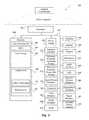
- FIG. 1illustrates a system environment in which various embodiments may be implemented
- FIG. 2illustrates a schematic embodiment of a client computer
- FIG. 3illustrates a schematic embodiment of a network computer
- FIG. 4illustrates a logical architecture of a system for anomaly detection using device relationship graphs in accordance with at least one of the various embodiments
- FIG. 5illustrates a logical representation of a network in accordance with at least one of the various embodiments
- FIG. 6illustrates a logical representation of a portion of a device relation model in accordance with at least one of the various embodiments
- FIGS. 7A and 7Billustrate how a device relation model may evolve as the NMCs gather more information about the relationships between the agents in a network
- FIGS. 8A and 8Bprovide additional illustration of how a device relation model may evolve as the NMCs gather more information about the relationships between the agents in a network;
- FIG. 9illustrates a logical architecture of a network that includes agents in accordance with the one or more embodiments
- FIG. 10illustrates a logical representation of a data structure for a device relation model that includes agents in accordance with the one or more embodiments
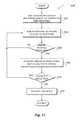
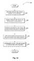
- FIG. 11illustrates an overview flowchart of a process for anomaly detection using device relationship graphs in accordance with at least one of the various embodiments
- FIG. 12illustrates a flowchart of a process for anomaly detection using device relationship graphs in accordance with at least one of the various embodiments
- FIG. 13illustrates a flowchart of a process for modeling agent relationships using device relation model in accordance with at least one of the various embodiments.
- FIG. 14illustrates a flowchart of a process for modeling agent relationships using device relation model in accordance with at least one of the various embodiments.
- the term “or”is an inclusive “or” operator, and is equivalent to the term “and/or,” unless the context clearly dictates otherwise.
- the term “based on”is not exclusive and allows for being based on additional factors not described, unless the context clearly dictates otherwise.
- the meaning of “a,” “an,” and “the”include plural references.
- the meaning of “in”includes “in” and “on.”
- the term “session”refers to a semi-permanent interactive packet interchange between two or more communicating endpoints, such as network devices.
- a sessionis set up or established at a certain point in time, and torn down at a later point in time.
- An established communication sessionmay involve more than one message in each direction.
- a sessionmay have stateful communication where at least one of the communicating network devices saves information about the session history to be able to communicate.
- a sessionmay also provide stateless communication, where the communication consists of independent requests with responses between the endpoints.
- An established sessionis the basic requirement to perform a connection-oriented communication.
- a sessionalso is the basic step to transmit in connectionless communication modes.
- connectionrefers to communication sessions with a semi-permanent connection for interactive packet interchange between two or more communicating endpoints, such as network devices.
- the connectionmay be established before application data is transferred, and where a stream of data is delivered in the same or different order than it was sent.
- the alternative to connection-oriented transmissionis connectionless communication.
- IPInternet Protocol
- UDPUniversal Datagram Protocol
- IPInternet Protocol
- UDPUniversal Datagram Protocol
- Packets associated with a TCP protocol connectionmay also be routed independently and could be delivered over different paths.
- the network communication systemmay provide the packets to application endpoints in the correct order.
- Connection-oriented communicationmay be a packet-mode virtual circuit connection.
- a transport layer virtual circuit protocolsuch as the TCP protocol can deliver packets of data in order although the lower layer switching is connectionless.
- a connection-oriented transport layer protocolsuch as TCP can also provide connection-oriented communications over connectionless communication. For example, if TCP is based on a connectionless network layer protocol (such as IP), this TCP/IP protocol can then achieve in-order delivery of a byte stream of data, by means of segment sequence numbering on the sender side, packet buffering and data packet reordering on the receiver side.
- IPconnectionless network layer protocol
- the virtual circuit connectionmay be established in a datalink layer or network layer switching mode, where all data packets belonging to the same traffic stream are delivered over the same path, and traffic flows are identified by some connection identifier rather than by complete routing information, which enables fast hardware based switching.
- the terms “session flow” and “network flow”refer to one or more network packets or a stream of network packets that are communicated in a session that is established between at least two endpoints, such as two network devices.
- flowsmay be useful if one or more of the endpoints of a session may be behind a network traffic management device, such as a firewall, switch, router, load balancer, or the like.
- a network traffic management devicesuch as a firewall, switch, router, load balancer, or the like.
- such flowsmay be used to ensure that the packets sent between the endpoints of a flow may be routed appropriately.
- establishing a TCP based connection between endpointsbegins with the execution of an initialization protocol and creates a single bi-directional flow between two endpoints, e.g., one direction of flow going from endpoint A to endpoint B, the other direction of the flow going from endpoint B to endpoint A, where each endpoint is at least identified by an IP address and a TCP port.
- protocols or network applicationsmay establish a separate flow for control information that enables management of at least one or more flows between two or more endpoints.
- network flowsmay be half-flows that may be unidirectional.
- tuplerefers to a set of values that identify a source and destination of a network packet, which may, under some circumstances, be a part of a network connection.
- a tuplemay include a source Internet Protocol (IP) address, a destination IP address, a source port number, a destination port number, virtual LAN segment identifier (VLAN ID), tunnel identifier, routing interface identifier, physical interface identifier, or a protocol identifier. Tuples may be used to identify network flows (e.g., connection flows).
- IPInternet Protocol
- VLAN IDvirtual LAN segment identifier
- Tuplesmay be used to identify network flows (e.g., connection flows).
- related flowsare network flows that while separate they are operating cooperatively.
- some protocolssuch as, FTP, SIP, RTP, VIOP, custom protocols, or the like, may provide control communication over one network flow and data communication over other network flows.
- configuration rulesmay define one or more criteria that are used to recognize that two or more network flows should be considered related flows. For example, configuration rules may define that flows containing a particular field value should be grouped with other flows having the same field value, such as, a cookie value, or the like.
- the terms “network monitor”, “network monitoring computer”, or “NMC”refer to an application (software, hardware, or some combination) that is arranged to monitor and record flows of packets in a session that are communicated between at least two endpoints over at least one network.
- the NMCcan provide information for assessing different aspects of these monitored flows.
- the NMCmay passively monitor network packet traffic without participating in the communication protocols. This monitoring may be performed for a variety of reasons, including troubleshooting and proactive remediation, end-user experience monitoring, SLA monitoring, capacity planning, application lifecycle management, infrastructure change management, infrastructure optimization, business intelligence, security, and regulatory compliance.
- the NMCcan receive network communication for monitoring through a variety of means including network taps, wireless receivers, port mirrors or directed tunnels from network switches, clients or servers including the endpoints themselves, or other infrastructure devices.
- the NMCmay receive a copy of each packet on a particular network segment or virtual local area network (VLAN). Also, for at least some of the various embodiments, they may receive these packet copies through a port mirror on a managed Ethernet switch, e.g., a Switched Port Analyzer (SPAN) port, a Roving Analysis Port (RAP), or the like, or combination thereof.
- Port mirroringenables analysis and debugging of network communications. Port mirroring can be performed for inbound or outbound traffic (or both) on single or multiple interfaces.
- the NMCmay track network connections from and to end points such as a client and/or a server.
- the NMCmay also extract information from the packets including protocol information at various layers of the communication protocol stack.
- the NMCmay reassemble or reconstruct the stream of data exchanged between the endpoints.
- the NMCmay perform decryption of the payload at various layers of the protocol stack.
- the NMCmay passively monitor the network traffic or it may participate in the protocols as a proxy.
- the NMCmay attempt to classify the network traffic according to communication protocols that are used.
- the NMCmay also perform one or more actions for classifying protocols that may be a necessary precondition for application classification. While some protocols run on well-known ports, others do not. Thus, even if there is traffic on a well-known port, it is not necessarily the protocol generally understood to be assigned to that port. As a result, the NMC may perform protocol classification using one or more techniques, such as, signature matching, statistical analysis, traffic analysis, and other heuristics. In some cases, the NMC may use adaptive protocol classification techniques where information used to classify the protocols may be accumulated and/or applied over time to further classify the observed protocols. In some embodiments, NMCs may be arranged to employ stateful analysis.
- an NMDmay use network packet payload data to drive a state machine that mimics the protocol state changes in the client/server flows being monitored.
- the NMCmay categorize the traffic where categories might include file transfers, streaming audio, streaming video, database access, interactive, gaming, and the like.
- the NMCmay attempt to determine whether the traffic corresponds to known communications protocols, such as HTTP, FTP, SMTP, RTP, TDS, TCP, IP, and the like.
- NMCs and/or NMC functionalitymay be implemented using hardware or software based proxy devices that may be arranged to intercept network traffic in the monitored networks.
- layerand “model layer” refer to a layer of one or more communication protocols in a stack of communication protocol layers that are defined by a model, such as the OSI model and the TCP/IP (IP) model.
- the OSI modeldefines seven layers and the TCP/IP model defines four layers of communication protocols.
- bitsare communicated between computing devices over some type of media, such as cables, network interface cards, radio wave transmitters, and the like.
- Data Linkbits are encoded into packets and packets are also decoded into bits.
- the Data Link layeralso has two sub-layers, the Media Access Control (MAC) sub-layer and the Logical Link Control (LLC) sub-layer.
- the MAC sub-layercontrols how a computing device gains access to the data and permission to transmit it.
- the LLC sub-layercontrols frame synchronization, flow control and error checking.
- Networklogical paths are created, known as virtual circuits, to communicated data from node to node. Routing, forwarding, addressing, internetworking, error handling, congestion control, and packet sequencing are functions of the Network layer.
- Transporttransparent transfer of data between end computing devices, or hosts, is provided. The Transport layer is responsible for end to end recovery and flow control to ensure complete data transfer over the network.
- the Session layersets up, coordinates, and terminates conversations, exchanges, and dialogues between applications at each end of a connection.
- the Session layersets up, coordinates, and terminates conversations, exchanges, and dialogues between applications at each end of a connection.
- independence from differences in data representation, e.g., encryptionis provided by translating from application to network format and vice versa.
- the Presentation layertransforms data into the form that the protocols at the Application layer (7) can accept.
- the Presentation layergenerally handles the formatting and encrypting/decrypting of data that is communicated across a network.
- the Application layerprovides services for file transfer, messaging, and displaying data.
- Protocols at the Application layerinclude FTP, HTTP, and Telnet.
- the TCP/IP modelcollapses the OSI model's Application, Presentation, and Session layers into its Application layer. Also, the OSI's Physical layer is either assumed or may be collapsed into the TCP/IP model's Link layer. Although some communication protocols may be listed at different numbered or named layers of the TCP/IP model versus the OSI model, both of these models describe stacks that include basically the same protocols.
- agentrefers to an actor in the monitored network. Agents may include applications, services, programs, processes, network devices, or the like, operating in the monitored network. For example, individual agents may include, web clients, web servers, database clients, database servers, mobile app clients, payment processors, groupware clients, groupware services, or the like. In some cases, multiple agents may co-exist on the same network computer, process, application, or cloud compute instance.
- Device relation modelrefers to a data structure that is used to represent relationships between and among different agents in a monitored network.
- Device relation modelsmay be graph models comprised of nodes and edges stored in the memory of a network computer.
- the network computermay automatically update the configuration and composition of the device relation model stored in the memory of the network computer to reflect the relationships between two or more agents in the monitored network.
- Nodes of the graph modelmay represent agents in the network and the edges of the graph model represent the relationship between agents in the network.
- Device relation modelsmay improve the performance of computers at least by enabling a compact representation of agents and relationships in large networks to reduce memory requirements.
- a device relation modelthat may be comprised of two or more nodes and one or more edges stored in memory of the network computer may be provided to a network monitoring computer (NMC), such that each node represents an agent and each edge represents a relationship between two agents.
- NMCnetwork monitoring computer
- providing the device relation modelmay include: adding one or more nodes to the device relation model based on the network traffic, wherein the one or more nodes each represent an agent in the network; and adding one or more edges to the device relation model based on the network traffic such that the one or more edges correspond to an association between two agents.
- providing the device relation modelmay include: providing one or more weight values that may be associated with the one or more edges such that the one or more weight values may indicate a strength of an association between two agents; and removing one or more of the one or more edges from the device relation model that may be associated with a weight value that may be less than a defined threshold.
- providing the device relation modelmay further include, if the network traffic from two or more non-associated agents may be correlated, one or more phantom edges may be added to the device relation model to associate the two or more non-associated agents with each other.
- providing the device relation modelmay also include: associating the one or more agents with applications based on their network traffic; and assigning the one or more agents to one or more groups based on their network traffic and their associated applications.
- the NMCmay be arranged to perform further actions to process the error signals.
- the one or more error signalsmay include monitored network traffic that is associated with one or more of application errors, timeouts, authentication errors, custom errors, or the like, or combination thereof.
- error signalsare not limited to the application layer.
- error signalsmay correspond to potential problems at the networking level, such as, TCP retransmits, throttles, and other transport related problems that may be known to cause application stalls.
- the device relation modelmay be traversed to identify one or more agents that may be associated with the one or more error signals such that the one or more agents may be associated with each other in the device relation model.
- the network traffic associated with the one or more error signals and the one or more agentsmay be analyzed by one or more NMCs.
- analyzing the network trafficmay further include: comparing a portion of the error signals that may be associated with one or more of the one or more agents with another portion of the error signals that may be associated with one or more other agents of the one or more agents; and associating the one or more error signals with the one or more anomalies of the network traffic based on a result of the comparison.
- one or more usersmay be notified of the one or more anomalies in the network.
- the device relation modelmay be updated based on the network, wherein the device relation model is updated upon a discovery of one or more of new computing devices in the network, new applications in the network, or new associations between agents.
- FIG. 1shows components of one embodiment of an environment in which embodiments of the invention may be practiced. Not all of the components may be required to practice the invention, and variations in the arrangement and type of the components may be made without departing from the spirit or scope of the invention.
- system 100 of FIG. 1includes local area networks (LANs)/wide area networks (WANs)—(network) 110 , wireless network 108 , client computers 102 - 105 , Application Server Computer 116 , Application Server Computer 117 , Network monitoring computer 119 , or the like.
- LANslocal area networks
- WANswide area networks
- client computers 102 - 105may operate over one or more wired and/or wireless networks, such as networks 108 , and/or 110 .
- client computers 102 - 105may include virtually any computer capable of communicating over a network to send and receive information, perform various online activities, offline actions, or the like.
- one or more of client computers 102 - 105may be configured to operate within a business or other entity to perform a variety of services for the business or other entity.
- client computers 102 - 105may be configured to operate as a web server, firewall, client application, media player, mobile telephone, game console, desktop computer, or the like.
- client computers 102 - 105are not constrained to these services and may also be employed, for example, as for end-user computing in other embodiments. It should be recognized that more or less client computers (as shown in FIG. 1 ) may be included within a system such as described herein, and embodiments are therefore not constrained by the number or type of client computers employed.
- Computers that may operate as client computer 102may include computers that typically connect using a wired or wireless communications medium such as personal computers, multiprocessor systems, microprocessor-based or programmable electronic devices, network PCs, or the like.
- client computers 102 - 105may include virtually any portable computer capable of connecting to another computer and receiving information such as, laptop computer 103 , mobile computer 104 , tablet computers 105 , or the like.
- portable computersare not so limited and may also include other portable computers such as cellular telephones, display pagers, radio frequency (RF) devices, infrared (IR) devices, Personal Digital Assistants (PDAs), handheld computers, wearable computers, integrated devices combining one or more of the preceding computers, or the like.
- client computers 102 - 105typically range widely in terms of capabilities and features.
- client computers 102 - 105may access various computing applications, including a browser, or other web-based application.
- a web-enabled client computermay include a browser application that is configured to send requests and receive responses over the web.
- the browser applicationmay be configured to receive and display graphics, text, multimedia, and the like, employing virtually any web-based language.
- the browser applicationis enabled to employ JavaScript, HyperText Markup Language (HTML), eXtensible Markup Language (XML), JavaScript Object Notation (JSON), Cascading Style Sheets (CSS), or the like, or combination thereof, to display and send a message.
- a user of the client computermay employ the browser application to perform various activities over a network (online). However, another application may also be used to perform various online activities.
- Client computers 102 - 105also may include at least one other client application that is configured to receive and/or send content between another computer.
- the client applicationmay include a capability to send and/or receive content, or the like.
- the client applicationmay further provide information that identifies itself, including a type, capability, name, and the like.
- client computers 102 - 105may uniquely identify themselves through any of a variety of mechanisms, including an Internet Protocol (IP) address, a phone number, Mobile Identification Number (MIN), an electronic serial number (ESN), a client certificate, or other device identifier.
- IPInternet Protocol
- MINMobile Identification Number
- ESNelectronic serial number
- client certificateor other device identifier.
- Such informationmay be provided in one or more network packets, or the like, sent between other client computers, application server computer 116 , application server computer 117 , network monitoring computer 118 , or other computers.
- Client computers 102 - 105may further be configured to include a client application that enables an end-user to log into an end-user account that may be managed by another computer, such as application server computer 116 , application server computer 117 , network monitoring computer 118 , or the like.
- Such an end-user accountin one non-limiting example, may be configured to enable the end-user to manage one or more online activities, including in one non-limiting example, project management, software development, system administration, configuration management, search activities, social networking activities, browse various websites, communicate with other users, or the like.
- client computersmay be arranged to enable users to provide configuration information, or the like, to network monitoring computer 118 .
- client computersmay be arranged to enable users to display reports, interactive user-interfaces, and/or results provided by network monitor computer 118 .
- Wireless network 108is configured to couple client computers 103 - 105 and its components with network 110 .
- Wireless network 108may include any of a variety of wireless sub-networks that may further overlay stand-alone ad-hoc networks, and the like, to provide an infrastructure-oriented connection for client computers 103 - 105 .
- Such sub-networksmay include mesh networks, Wireless LAN (WLAN) networks, cellular networks, and the like.
- the systemmay include more than one wireless network.
- Wireless network 108may further include an autonomous system of terminals, gateways, routers, and the like connected by wireless radio links, and the like. These connectors may be configured to move freely and randomly and organize themselves arbitrarily, such that the topology of wireless network 108 may change rapidly.
- Wireless network 108may further employ a plurality of access technologies including 2nd (2G), 3rd (3G), 4th (4G) 5th (5G) generation radio access for cellular systems, WLAN, Wireless Router (WR) mesh, and the like.
- Access technologiessuch as 2G, 3G, 4G, 5G, and future access networks may enable wide area coverage for mobile computers, such as client computers 103 - 105 with various degrees of mobility.
- wireless network 108may enable a radio connection through a radio network access such as Global System for Mobil communication (GSM), General Packet Radio Services (GPRS), Enhanced Data GSM Environment (EDGE), code division multiple access (CDMA), time division multiple access (TDMA), Wideband Code Division Multiple Access (WCDMA), High Speed Downlink Packet Access (HSDPA), Long Term Evolution (LTE), and the like.
- GSMGlobal System for Mobil communication
- GPRSGeneral Packet Radio Services
- EDGEEnhanced Data GSM Environment
- CDMAcode division multiple access
- TDMAtime division multiple access
- WCDMAWideband Code Division Multiple Access
- HSDPAHigh Speed Downlink Packet Access
- LTELong Term Evolution
- Network 110is configured to couple network computers with other computers, including, application server computer 116 , application server computer 117 , network monitoring computer 118 , client computers 102 - 105 through wireless network 108 , or the like.
- Network 110is enabled to employ any form of computer readable media for communicating information from one electronic device to another.
- network 110can include the Internet in addition to local area networks (LANs), wide area networks (WANs), direct connections, such as through a universal serial bus (USB) port, Ethernet port, other forms of computer-readable media, or any combination thereof.
- LANslocal area networks
- WANswide area networks
- USBuniversal serial bus
- Ethernet portsuch as Ethernet port
- a routeracts as a link between LANs, enabling messages to be sent from one to another.
- communication links within LANstypically include twisted wire pair or coaxial cable
- communication links between networksmay utilize analog telephone lines, full or fractional dedicated digital lines including T1, T2, T3, and T4, and/or other carrier mechanisms including, for example, E-carriers, Integrated Services Digital Networks (ISDNs), Digital Subscriber Lines (DSLs), wireless links including satellite links, or other communications links known to those skilled in the art.
- ISDNsIntegrated Services Digital Networks
- DSLsDigital Subscriber Lines
- communication linksmay further employ any of a variety of digital signaling technologies, including without limit, for example, DS-0, DS-1, DS-2, DS-3, DS-4, OC-3, OC-12, OC-48, or the like.
- remote computers and other related electronic devicescould be remotely connected to either LANs or WANs via a modem and temporary telephone link.
- network 110may be configured to transport information of an Internet Protocol (IP).
- IPInternet Protocol
- communication mediatypically embodies computer readable instructions, data structures, program modules, or other transport mechanism and includes any information non-transitory delivery media or transitory delivery media.
- communication mediaincludes wired media such as twisted pair, coaxial cable, fiber optics, wave guides, and other wired media and wireless media such as acoustic, RF, infrared, and other wireless media.
- application server computer 116 and/or application server computer 117is described in more detail below in conjunction with FIG. 3 . Briefly, however, application server computer 116 - 117 includes virtually any network computer capable of hosting applications and/or providing services in network environment.
- network monitoring computer 118may include include virtually any network computer capable of passively monitoring communication traffic in a network environment.
- FIG. 1illustrates application server computer 116 , application server computer 117 , and network monitor device 118 , each as a single computer, the innovations and/or embodiments are not so limited.
- one or more functions of application server computers 116 - 117 , and/or network monitoring computer 118 , or the like,may be distributed across one or more distinct network computers.
- network monitoring computer 118may be implemented using a plurality of network computers.
- application server computers 116 - 117 , and/or network monitoring computer 118may be implemented using one or more cloud instances in one or more cloud networks. Accordingly, these innovations and embodiments are not to be construed as being limited to a single environment, and other configurations, and other architectures are also envisaged.
- FIG. 2shows one embodiment of client computer 200 that may include many more or less components than those shown.
- Client computer 200may represent, for example, at least one embodiment of mobile computers or client computers shown in FIG. 1 .
- Client computer 200may include processor 202 in communication with memory 204 via bus 228 .
- Client computer 200may also include power supply 230 , network interface 232 , audio interface 256 , display 250 , keypad 252 , illuminator 254 , video interface 242 , input/output interface 238 , haptic interface 264 , global positioning systems (GPS) receiver 258 , open air gesture interface 260 , temperature interface 262 , camera(s) 240 , projector 246 , pointing device interface 266 , processor-readable stationary storage device 234 , and processor-readable removable storage device 236 .
- Client computer 200may optionally communicate with a base station (not shown), or directly with another computer. And in one embodiment, although not shown, a gyroscope may be employed within client computer 200 to measuring and/or maintaining an orientation of client computer 200 .
- Power supply 230may provide power to client computer 200 .
- a rechargeable or non-rechargeable batterymay be used to provide power.
- the powermay also be provided by an external power source, such as an AC adapter or a powered docking cradle that supplements and/or recharges the battery.
- Network interface 232includes circuitry for coupling client computer 200 to one or more networks, and is constructed for use with one or more communication protocols and technologies including, but not limited to, protocols and technologies that implement any portion of the OSI model for mobile communication (GSM), CDMA, time division multiple access (TDMA), UDP, TCP/IP, SMS, MMS, GPRS, WAP, UWB, WiMax, SIP/RTP, GPRS, EDGE, WCDMA, LTE, UMTS, OFDM, CDMA2000, EV-DO, HSDPA, or any of a variety of other wireless communication protocols.
- GSMOSI model for mobile communication
- CDMACode Division Multiple Access
- TDMAtime division multiple access
- UDPUser Datagram Protocol/IP
- SMSSMS
- MMSmobility management Entity
- GPRSWireless Fidelity
- WAPWireless Fidelity
- UWBWireless Fidelity
- WiMaxWireless Fidelity
- SIP/RTPGPRS
- EDGEWCDMA
- Audio interface 256may be arranged to produce and receive audio signals such as the sound of a human voice.
- audio interface 256may be coupled to a speaker and microphone (not shown) to enable telecommunication with others and/or generate an audio acknowledgement for some action.
- a microphone in audio interface 256can also be used for input to or control of client computer 200 , e.g., using voice recognition, detecting touch based on sound, and the like.
- Display 250may be a liquid crystal display (LCD), gas plasma, electronic ink, light emitting diode (LED), Organic LED (OLED) or any other type of light reflective or light transmissive display that can be used with a computer.
- Display 250may also include a touch interface 244 arranged to receive input from an object such as a stylus or a digit from a human hand, and may use resistive, capacitive, surface acoustic wave (SAW), infrared, radar, or other technologies to sense touch and/or gestures.
- SAWsurface acoustic wave
- Projector 246may be a remote handheld projector or an integrated projector that is capable of projecting an image on a remote wall or any other reflective object such as a remote screen.
- Video interface 242may be arranged to capture video images, such as a still photo, a video segment, an infrared video, or the like.
- video interface 242may be coupled to a digital video camera, a web-camera, or the like.
- Video interface 242may comprise a lens, an image sensor, and other electronics.
- Image sensorsmay include a complementary metal-oxide-semiconductor (CMOS) integrated circuit, charge-coupled device (CCD), or any other integrated circuit for sensing light.
- CMOScomplementary metal-oxide-semiconductor
- CCDcharge-coupled device
- Keypad 252may comprise any input device arranged to receive input from a user.
- keypad 252may include a push button numeric dial, or a keyboard.
- Keypad 252may also include command buttons that are associated with selecting and sending images.
- Illuminator 254may provide a status indication and/or provide light. Illuminator 254 may remain active for specific periods of time or in response to event messages. For example, when illuminator 254 is active, it may backlight the buttons on keypad 252 and stay on while the client computer is powered. Also, illuminator 254 may backlight these buttons in various patterns when particular actions are performed, such as dialing another client computer. Illuminator 254 may also cause light sources positioned within a transparent or translucent case of the client computer to illuminate in response to actions.
- client computer 200may also comprise hardware security module (HSM) 268 for providing additional tamper resistant safeguards for generating, storing and/or using security/cryptographic information such as, keys, digital certificates, passwords, passphrases, two-factor authentication information, or the like.
- HSMhardware security module
- hardware security modulemay be employed to support one or more standard public key infrastructures (PKI), and may be employed to generate, manage, and/or store keys pairs, or the like.
- PKIpublic key infrastructure
- HSM 268may be a stand-alone computer, in other cases, HSM 268 may be arranged as a hardware card that may be added to a client computer.
- Client computer 200may also comprise input/output interface 238 for communicating with external peripheral devices or other computers such as other client computers and network computers.
- the peripheral devicesmay include an audio headset, virtual reality headsets, display screen glasses, remote speaker system, remote speaker and microphone system, and the like.
- Input/output interface 238can utilize one or more technologies, such as Universal Serial Bus (USB), Infrared, WiFi, WiMax, BluetoothTM, and the like.
- Input/output interface 238may also include one or more sensors for determining geolocation information (e.g., GPS), monitoring electrical power conditions (e.g., voltage sensors, current sensors, frequency sensors, and so on), monitoring weather (e.g., thermostats, barometers, anemometers, humidity detectors, precipitation scales, or the like), or the like.
- Sensorsmay be one or more hardware sensors that collect and/or measure data that is external to client computer 200 .
- Haptic interface 264may be arranged to provide tactile feedback to a user of the client computer.
- the haptic interface 264may be employed to vibrate client computer 200 in a particular way when another user of a computer is calling.
- Temperature interface 262may be used to provide a temperature measurement input and/or a temperature changing output to a user of client computer 200 .
- Open air gesture interface 260may sense physical gestures of a user of client computer 200 , for example, by using single or stereo video cameras, radar, a gyroscopic sensor inside a computer held or worn by the user, or the like.
- Camera 240may be used to track physical eye movements of a user of client computer 200 .
- GPS transceiver 258can determine the physical coordinates of client computer 200 on the surface of the Earth, which typically outputs a location as latitude and longitude values. GPS transceiver 258 can also employ other geo-positioning mechanisms, including, but not limited to, triangulation, assisted GPS (AGPS), Enhanced Observed Time Difference (E-OTD), Cell Identifier (CI), Service Area Identifier (SAI), Enhanced Timing Advance (ETA), Base Station Subsystem (BSS), or the like, to further determine the physical location of client computer 200 on the surface of the Earth. It is understood that under different conditions, GPS transceiver 258 can determine a physical location for client computer 200 . In at least one embodiment, however, client computer 200 may, through other components, provide other information that may be employed to determine a physical location of the client computer, including for example, a Media Access Control (MAC) address, IP address, and the like.
- MACMedia Access Control
- Human interface componentscan be peripheral devices that are physically separate from client computer 200 , allowing for remote input and/or output to client computer 200 .
- information routed as described here through human interface componentssuch as display 250 or keyboard 252 can instead be routed through network interface 232 to appropriate human interface components located remotely.
- human interface peripheral componentsthat may be remote include, but are not limited to, audio devices, pointing devices, keypads, displays, cameras, projectors, and the like. These peripheral components may communicate over a Pico Network such as BluetoothTM, ZigbeeTM and the like.
- a client computer with such peripheral human interface componentsis a wearable computer, which might include a remote pico projector along with one or more cameras that remotely communicate with a separately located client computer to sense a user's gestures toward portions of an image projected by the pico projector onto a reflected surface such as a wall or the user's hand.
- a client computermay include web browser application 226 that is configured to receive and to send web pages, web-based messages, graphics, text, multimedia, and the like.
- the client computer's browser applicationmay employ virtually any programming language, including a wireless application protocol messages (WAP), and the like.
- WAPwireless application protocol
- the browser applicationis enabled to employ Handheld Device Markup Language (HDML), Wireless Markup Language (WML), WMLScript, JavaScript, Standard Generalized Markup Language (SGML), HyperText Markup Language (HTML), eXtensible Markup Language (XML), HTML5, and the like.
- HDMLHandheld Device Markup Language
- WMLWireless Markup Language
- WMLScriptWireless Markup Language
- JavaScriptStandard Generalized Markup Language
- SGMLStandard Generalized Markup Language
- HTMLHyperText Markup Language
- XMLeXtensible Markup Language
- HTML5HyperText Markup Language
- Memory 204may include RAM, ROM, and/or other types of memory. Memory 204 illustrates an example of computer-readable storage media (devices) for storage of information such as computer-readable instructions, data structures, program modules or other data. Memory 204 may store BIOS 208 for controlling low-level operation of client computer 200 . The memory may also store operating system 206 for controlling the operation of client computer 200 . It will be appreciated that this component may include a general-purpose operating system such as a version of UNIX, or LINUXTM, or a specialized client computer communication operating system such as Windows PhoneTM, or the Symbian® operating system. The operating system may include, or interface with a Java virtual machine module that enables control of hardware components and/or operating system operations via Java application programs.
- BIOS 208for controlling low-level operation of client computer 200 .
- the memorymay also store operating system 206 for controlling the operation of client computer 200 . It will be appreciated that this component may include a general-purpose operating system such as a version of UNIX, or LINU
- Memory 204may further include one or more data storage 210 , which can be utilized by client computer 200 to store, among other things, applications 220 and/or other data.
- data storage 210may also be employed to store information that describes various capabilities of client computer 200 . The information may then be provided to another device or computer based on any of a variety of methods, including being sent as part of a header during a communication, sent upon request, or the like.
- Data storage 210may also be employed to store social networking information including address books, buddy lists, aliases, user profile information, or the like.
- Data storage 210may further include program code, data, algorithms, and the like, for use by a processor, such as processor 202 to execute and perform actions.
- data storage 210might also be stored on another component of client computer 200 , including, but not limited to, non-transitory processor-readable removable storage device 236 , processor-readable stationary storage device 234 , or even external to the client computer.
- Applications 220may include computer executable instructions which, when executed by client computer 200 , transmit, receive, and/or otherwise process instructions and data. Applications 220 may include, for example, other client applications 224 , web browser 226 , or the like. Client computers may be arranged to exchange communications, such as, queries, searches, messages, notification messages, event messages, alerts, performance metrics, log data, API calls, or the like, combination thereof, with application servers and/or network monitoring computers.
- application programsinclude calendars, search programs, email client applications, IM applications, SMS applications, Voice Over Internet Protocol (VOIP) applications, contact managers, task managers, transcoders, database programs, word processing programs, security applications, spreadsheet programs, games, search programs, and so forth.
- VOIPVoice Over Internet Protocol
- client computer 200may include an embedded logic hardware device instead of a CPU, such as, an Application Specific Integrated Circuit (ASIC), Field Programmable Gate Array (FPGA), Programmable Array Logic (PAL), or the like, or combination thereof.
- the embedded logic hardware devicemay directly execute its embedded logic to perform actions.
- client computer 200may include a hardware microcontroller instead of a CPU.
- the microcontrollermay directly execute its own embedded logic to perform actions and access its own internal memory and its own external Input and Output Interfaces (e.g., hardware pins and/or wireless transceivers) to perform actions, such as System On a Chip (SOC), or the like.
- SOCSystem On a Chip
- FIG. 3shows one embodiment of network computer 300 that may be included in a system implementing at least one of the various embodiments.
- Network computer 300may include many more or less components than those shown in FIG. 3 . However, the components shown are sufficient to disclose an illustrative embodiment for practicing these innovations.
- Network computer 300may represent, for example, one embodiment of at least one of application server computers 116 - 117 and/or network monitoring computer 118 of FIG. 1 .
- network computer 300includes a processor 302 that may be in communication with a memory 304 via a bus 328 .
- processor 302may be comprised of one or more hardware processors, or one or more processor cores.
- one or more of the one or more processorsmay be specialized processors designed to perform one or more specialized actions, such as, those described herein.
- Network computer 300also includes a power supply 330 , network interface 332 , audio interface 356 , display 350 , keyboard 352 , input/output interface 338 , processor-readable stationary storage device 334 , and processor-readable removable storage device 336 .
- Power supply 330provides power to network computer 300 .
- Network interface 332includes circuitry for coupling network computer 300 to one or more networks, and is constructed for use with one or more communication protocols and technologies including, but not limited to, protocols and technologies that implement any portion of the Open Systems Interconnection model (OSI model), global system for mobile communication (GSM), code division multiple access (CDMA), time division multiple access (TDMA), user datagram protocol (UDP), transmission control protocol/Internet protocol (TCP/IP), Short Message Service (SMS), Multimedia Messaging Service (MMS), general packet radio service (GPRS), WAP, ultra wide band (UWB), IEEE 802.16 Worldwide Interoperability for Microwave Access (WiMax), Session Initiation Protocol/Real-time Transport Protocol (SIP/RTP), or any of a variety of other wired and wireless communication protocols.
- Network interface 332is sometimes known as a transceiver, transceiving device, or network interface card (NIC).
- Network computer 300may optionally communicate with a base station (not shown), or directly with another computer.
- Audio interface 356is arranged to produce and receive audio signals such as the sound of a human voice.
- audio interface 356may be coupled to a speaker and microphone (not shown) to enable telecommunication with others and/or generate an audio acknowledgement for some action.
- a microphone in audio interface 356can also be used for input to or control of network computer 300 , for example, using voice recognition.
- Display 350may be a liquid crystal display (LCD), gas plasma, electronic ink, light emitting diode (LED), Organic LED (OLED) or any other type of light reflective or light transmissive display that can be used with a computer.
- Display 350may be a handheld projector or pico projector capable of projecting an image on a wall or other object.
- Network computer 300may also comprise input/output interface 338 for communicating with external devices or computers not shown in FIG. 3 .
- Input/output interface 338can utilize one or more wired or wireless communication technologies, such as USBTM, FirewireTM, WiFi, WiMax, ThunderboltTM, Infrared, BluetoothTM, ZigbeeTM, serial port, parallel port, and the like.
- input/output interface 338may also include one or more sensors for determining geolocation information (e.g., GPS), monitoring electrical power conditions (e.g., voltage sensors, current sensors, frequency sensors, and so on), monitoring weather (e.g., thermostats, barometers, anemometers, humidity detectors, precipitation scales, or the like), or the like.
- Sensorsmay be one or more hardware sensors that collect and/or measure data that is external to network computer 300 .
- Human interface componentscan be physically separate from network computer 300 , allowing for remote input and/or output to network computer 300 . For example, information routed as described here through human interface components such as display 350 or keyboard 352 can instead be routed through the network interface 332 to appropriate human interface components located elsewhere on the network.
- Human interface componentsinclude any component that allows the computer to take input from, or send output to, a human user of a computer. Accordingly, pointing devices such as mice, styluses, track balls, or the like, may communicate through pointing device interface 358 to receive user input.
- GPS transceiver 340can determine the physical coordinates of network computer 300 on the surface of the Earth, which typically outputs a location as latitude and longitude values. GPS transceiver 340 can also employ other geo-positioning mechanisms, including, but not limited to, triangulation, assisted GPS (AGPS), Enhanced Observed Time Difference (E-OTD), Cell Identifier (CI), Service Area Identifier (SAI), Enhanced Timing Advance (ETA), Base Station Subsystem (BSS), or the like, to further determine the physical location of network computer 300 on the surface of the Earth. It is understood that under different conditions, GPS transceiver 340 can determine a physical location for network computer 300 . In at least one embodiment, however, network computer 300 may, through other components, provide other information that may be employed to determine a physical location of the client computer, including for example, a Media Access Control (MAC) address, IP address, and the like.
- MACMedia Access Control
- Memory 304may include Random Access Memory (RAM), Read-Only Memory (ROM), and/or other types of memory.
- Memory 304illustrates an example of computer-readable storage media (devices) for storage of information such as computer-readable instructions, data structures, program modules or other data.
- Memory 304stores a basic input/output system (BIOS) 308 for controlling low-level operation of network computer 300 .
- BIOSbasic input/output system
- the memoryalso stores an operating system 306 for controlling the operation of network computer 300 .
- this componentmay include a general-purpose operating system such as a version of UNIX, or LINUXTM, or a specialized operating system such as Microsoft Corporation's Windows® operating system, or the Apple Corporation's IOS® operating system.
- the operating systemmay include, or interface with a Java virtual machine module that enables control of hardware components and/or operating system operations via Java application programs. Likewise, other runtime environments may be included.
- Memory 304may further include one or more data storage 310 , which can be utilized by network computer 300 to store, among other things, applications 320 and/or other data.
- data storage 310may also be employed to store information that describes various capabilities of network computer 300 . The information may then be provided to another device or computer based on any of a variety of methods, including being sent as part of a header during a communication, sent upon request, or the like.
- Data storage 410may also be employed to store social networking information including address books, buddy lists, aliases, user profile information, or the like.
- Data storage 310may further include program code, data, algorithms, and the like, for use by a processor, such as processor 302 to execute and perform actions such as those actions described below.
- Data storage 310might also be stored on another component of network computer 300 , including, but not limited to, non-transitory media inside processor-readable removable storage device 336 , processor-readable stationary storage device 334 , or any other computer-readable storage device within network computer 300 , or even external to network computer 300 .
- Data storage 310may include, for example, capture database 312 , graph database 314 , protocol information 316 , or the like.
- Capture database 312may be a data store that contains one or more records, logs, events, or the like, produced during monitoring of the networks.
- Graph database 314may be arranged to store one or more data structures that represent device relation models.
- protocol information 316may store various rules and/or configuration information related to one or more network communication protocols (e.g., HL7) that may be employed, or the like.
- Applications 320may include computer executable instructions which, when executed by network computer 300 , transmit, receive, and/or otherwise process messages (e.g., SMS, Multimedia Messaging Service (MMS), Instant Message (IM), email, and/or other messages), audio, video, and enable telecommunication with another user of another mobile computer.
- Other examples of application programsinclude calendars, search programs, email client applications, IM applications, SMS applications, Voice Over Internet Protocol (VOIP) applications, contact managers, task managers, transcoders, database programs, word processing programs, security applications, spreadsheet programs, games, search programs, and so forth.
- Applications 320may include network monitoring application 322 that perform actions further described below.
- one or more of the applicationsmay be implemented as modules and/or components of another application. Further, in at least one of the various embodiments, applications may be implemented as operating system extensions, modules, plugins, or the like.
- network monitoring application 322may be operative in a cloud-based computing environment.
- these applications, and others, that comprise the management platformmay be executing within virtual machines and/or virtual servers that may be managed in a cloud-based based computing environment.
- the applicationsmay flow from one physical network computer within the cloud-based environment to another depending on performance and scaling considerations automatically managed by the cloud computing environment.
- virtual machines and/or virtual servers dedicated to network monitoring application 322may be provisioned and de-commissioned automatically.
- network monitoring application 322may be located in virtual servers running in a cloud-based computing environment rather than being tied to one or more specific physical network computers.
- network computer 300may also comprise hardware security module (HSM) 360 for providing additional tamper resistant safeguards for generating, storing and/or using security/cryptographic information such as, keys, digital certificates, passwords, passphrases, two-factor authentication information, or the like.
- HSMhardware security module
- hardware security modulemay be employ to support one or more standard public key infrastructures (PKI), and may be employed to generate, manage, and/or store keys pairs, or the like.
- PKIpublic key infrastructure
- HSM 360may be a stand-alone network computer, in other cases, HSM 360 may be arranged as a hardware card that may be installed in a network computer.
- the network computermay include an embedded logic hardware device instead of a CPU, such as, an Application Specific Integrated Circuit (ASIC), Field Programmable Gate Array (FPGA), Programmable Array Logic (PAL), or the like, or combination thereof.
- the embedded logic hardware devicemay directly execute its embedded logic to perform actions.
- the network computermay include one or more hardware microcontrollers instead of a CPU.
- the one or more microcontrollersmay directly execute their own embedded logic to perform actions and access their own internal memory and their own external Input and Output Interfaces (e.g., hardware pins and/or wireless transceivers) to perform actions, such as System On a Chip (SOC), or the like.
- SOCSystem On a Chip
- FIG. 4illustrates a logical architecture of system 400 for anomaly detection using device relationship graphs in accordance with at least one of the various embodiments.
- System 400may be arranged to include a plurality of network devices and/or network computers on first network 402 and a plurality of network devices and/or network computers on second network 404 . Communication between the first network and the second network is managed by switch 406 .
- NMC 408may be arranged to passively monitor and/or record packets (network packets) that are communicated in network connection flows between network devices and/or network computers on first network 402 and second network 404 . For example, the communication of flows of packets between the Host B network computer and the Host A network computer are managed by switch 406 and NMC 408 may be passively monitoring and recording some or all of the network traffic comprising these flows.
- NMC 408may be arranged to passively monitor network communication between and among hosts that are on the same network, such as, network computers 402 .
- NMC 408may be arranged to receive network communication for monitoring through a variety of means including network taps, wireless receivers, port mirrors or directed tunnels from network switches, clients or servers including the endpoints themselves, or other infrastructure devices.
- the NMCmay receive a copy of each packet on a particular network segment or virtual local area network (VLAN).
- NMCsmay receive these packet copies through a port mirror on a managed Ethernet switch, e.g., a Switched Port Analyzer (SPAN) port, or a Roving Analysis Port (RAP).
- Port mirroringenables analysis and debugging of network communications. Port mirroring can be performed for inbound or outbound traffic (or both) on single or multiple interfaces.
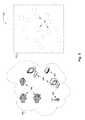
- FIG. 5illustrates a logical representation of network 500 in accordance with at least one of the various embodiments.
- network 502represent a physical network and the objects in the network.
- network 502includes, network computers 504 , client computers 506 , network devices, such as, network device 510 , and other items, such as, WI-FI hotspot 508 .
- networksmay have many more and/or different devices than shown in FIG. 5 .
- one or more network monitoring computersmay be arranged to monitor networks, such as, network 502 . (See, FIG. 4 ).
- NMCsmay be arranged to generate a device relation model that represents the items in a network.
- device relation model 512represents a device relation model corresponding to network 502 .
- device relation model 512includes nodes that represent the various agents that may be active in network 502 .
- agents 514may represent some of the agents that are operative in network 502 .
- device relation model 512shows nodes that corresponds to agents absent any edges.
- initially some or all of the relationships between the agentsmay be unknown to the monitoring NMC, so some or all of the edges may be unknown and therefor omitted from device relation model 512 .
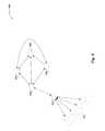
- FIG. 6illustrates a logical representation of a portion of device relation model 600 in accordance with at least one of the various embodiments.
- device relation modelsmay include nodes that represent agents and edges that represent relationships between the agents.
- agentsmay represent servers, clients, switches, routers, NMCs, load balancers, or the like.
- agent 602may be a server agent that has relationships with other servers, such as, agent 604 and agent 606 .
- agent 608may be a server or other service that has a relationship with agent 604 , agent 606 , and agent 602 .
- agent 604 and agent 610may have a relationship and client agents 612 may have direct relationships with agent 610 .
- NMCsmay be arranged to use device relation model 600 to discover relationships between groups of agents.
- device relation model 600may be used to determine that agent 602 , agent 604 , 610 , and client 612 may be in a related group because they are all on the same path through the graph.
- FIGS. 7A and 7Billustrate how a device relation model may evolve as the NMCs gather more information about the relationships between the agents in a network.
- FIG. 7Aillustrates a logical representation of device relation model 700 showing na ⁇ ve relationships between the agents in accordance with the one or more embodiments.
- a NMCmay initially determine the agents in a network by observing the network traffic to obtain the source/destination network address fields in the network packets that flow through the network.
- each unique network addressmay represent a different agent in the network.
- the NMCmay be arranged to observe responses to broadcast messages, or the like.
- the NMCmay be provided other configuration that defines some or all of the agents in the network.
- the NMChas discovered/identified six agents in the network (agent 702 through agent 712 ). Accordingly, in some embodiments, the NMC may be arranged to generate a device relation model, such as, device relation model 700 that represents the six discovered agents as nodes in the graph. Likewise, in some embodiments, edges in device relation model 700 may represent the initial relationships as determined by the NMC. For example, in the initial stages of monitoring a network the NMC may be arranged to determine relationships based on which agents are observed to be communicating with each other.
- a device relation modelsuch as, device relation model 700 that represents the six discovered agents as nodes in the graph.
- edges in device relation model 700may represent the initial relationships as determined by the NMC. For example, in the initial stages of monitoring a network the NMC may be arranged to determine relationships based on which agents are observed to be communicating with each other.
- NMCsmay be arranged to provide a device relation model that represents the relationships between the agents. Initially, in some embodiments, the NMC may define the initial relationships in the network based on which agents communicate with each other. However, in at least one of the various embodiments, as the NMC collects more information about the agents and their relationships to other agents, the NMC may modify device relation model 700 to reflect the deeper understanding of these relationships.
- FIG. 7Billustrates a logical representation of device relation model 700 showing informed relationships between the agents in accordance with the one or more embodiments.
- the NMCmay have observed enough network traffic to evaluate and weight the relationships of the agents in the network.
- the NMCmay be arranged to remove (or de-prioritize) edges from device relation model 700 that correspond to such relationships.
- agentse.g., Windows network domain controllers
- a networkmay be arranged to periodically exchange messages with one or more other agents for discovery/accountability purposes.
- some of the messaging observed by an NMCmay be routing and otherwise not resulting from an interesting relationship between the sender and receiver.
- NMCmay be arranged to evaluate the communication between agents to attempt to determine the type of relationships and the importance of the relationships. Accordingly, in at least one of the various embodiments, NMCs may be arranged to collected metrics associated with the various network flows flowing the network to identify the flows that may be important. Likewise, in at least one of the various embodiments, NMC may be arranged discover and recognize the communication protocols used by agents in monitored networks. In some embodiments, the NMCs may be arranged to use the collected metrics and its understanding of the communication protocol to establish and/or prioritize relationships between the agents in the networks.
- device relation model 700has been modified to include relationships determined to be of importance.
- the nodes representing agents 702 - 712are still present in but some of the edges that represent relationships in the network have been removed.
- device relation model 700includes an edge between agent 704 and agent 712 .
- device relation model 700omits the edge between agent 704 and agent 712 .
- the remaining edges in device relation model 700represent relationships between the agents that the NMC determined to be important.
- NMCmay employ a variety of metrics, conditions, heuristics, or the like, to identify relationships that may be of interest.
- an NMCmay be arranged to identify agents that represent certain applications on the network, such as, database servers, database clients, email servers, email clients, or the like, by identifying the communication protocols that may be used by the particular applications.
- the NMCmay determine an important relationship based on the number and/or rate of packets exchanged between one or more agents. Accordingly, the NMC may be configured to prioritize relationships between agents that exchange a high volume of traffic.
- the NMCmay analyze observed traffic to identify network packets that flow through particular paths in the device relation model.
- NMCsmay be arranged to trace or identify such paths connecting related agents by observing common data carried in the payloads and/or header fields of the network packets that are passed among agents in the network.
- an NMCmay be arranged to observe sequence numbers, session identifiers, HTTP cookies, query values, or the like, from all agent participating in transactions on the network.
- the NMCmay correlate observed network packets that may be requests and responses based on the contents of the network packets and information about the operation of the underlying applications and/or protocols.
- FIGS. 8A and 8Bprovide additional illustration of how a device relation model may evolve as the NMCs gather more information about the relationships between the agents in a network.
- FIG. 8Aillustrates a logical representation of device relation model 800 showing relationships between the agents based on observed network connections in accordance with the one or more embodiments.
- the NMChas provided device relation model 800 that represents the relationships between agent 802 through agent 812 .
- device relation model 800shows relationships that may be associated with actual network links (e.g., physical links or virtual links) between the agents in the network.
- the edges in device relation model 800may correspond to network flows that have been observed in the network.
- an NMCmay readily deduce these types of connection relationships by examining the source/destination fields in network packets observed in the network. Accordingly, in this example, agent 806 may have been observed exchanging data with agent 808 over the network.
- FIG. 8Billustrates a logical representation of device relation model 800 showing phantom edges that represent relationships between the agents in accordance with the one or more embodiments.
- networksmay include agents that have important logical/operational relationships even though they do not exchange network packets directly with each other.
- the NMChas discovered relationships between agent 802 and agent 808 even though they do not communicate directly with each other.
- the NMChas discovered relationships between agent 804 and agent 812 even though they do not communicate directly with each other.
- agent 808 , agent 810 , agent 812have also been found to be related even though their no direct network link or communication between them.
- the NMCmay be arranged to represent such relationships using phantom edges. Phantom edges may represent relationships between agents that do not correspond to direct network links.
- agent 802 and agent 804may be database clients and agent 808 , agent 810 , and agent 812 may be database servers.
- agent 802 and agent 804access the database servers through agent 806 .
- agent 806may be proxy-based load balancer of some kind. Accordingly, in this example there is no direct network link between the database clients and the database servers. Nor, as represented, do the database server agents (agent 808 , agent 810 , and agent 812 ) have direct connections to each other.
- the NMCmay determine that the three database server agents (agent 808 , agent 810 , and agent 812 ) are related because they are each receiving communications from the same load balancer (agent 806 ). Likewise, the NMC may determine a relationship between the database clients (agent 802 and agent 804 ) and the database servers (agent 808 , agent 810 , and agent 812 ) by observing the operation of the database transactions even though they do not communicate directly with each other.
- FIG. 9illustrates a logical architecture of network 900 that includes agents in accordance with the one or more embodiments.
- networksmay include several (100s, 1000s, or more) computers and/or devices that may put network traffic on the network.
- network monitoring computersNMCs
- NMCsmay be arranged to passively monitor the network traffic.
- NMCsmay have direct access to the wire traffic of the network enabling NMCs to access all of the network traffic in monitored networks.
- the NMCmay be arranged to identify agents in the network.
- Agentsmay include applications, services, programs, processes, network devices, or the like, operating in the monitored network.
- individual agentsmay include, web clients, web servers, database clients, database servers, mobile app clients, payment processors, groupware clients, groupware services, or the like.
- multiple agentsmay co-exist on the same network computer or cloud compute instance.
- client computer 902may be hosting web client 904 and DNS client 906 .
- server computer 908may be hosting web server 910 , database client 914 , and DNS client 921 .
- server computer 916may be arranged to host database server 918 and authorization client 920 ;
- server computer 922may be arranged to host authorization server 924 ;
- server computer 926may be arranged to DNS server 928 .
- some or all of the applications on a computermay correspond to agents.
- applications, services, or the like, that communicate using the networkmay be identified as agents by an NMC. Accordingly, there may be more than one agent per computer.
- Some server computersmay host many agents. Also, some server computers may be virtualized machine instances executing in a virtualized environment, such as, a cloud-based computing environment.
- an individual process or program running on a network computermay perform more than one type of operation on the network. Accordingly, some processes or programs may be represented as more than one agent.
- a web server applicationmay have an embedded database client.
- an individual web server applicationmay contribute two or more agents to the device relation model.
- the NMCmay be arranged to monitor the network traffic to identify the agents and to determine their roles. In at least one of the various embodiments, the NMC may monitor the communication protocols, payloads, ports, source/destination addresses, or the like, or combination thereof, to identify agents.
- the NMCmay be preloaded with configuration information that it may use to identify agents and the services/roles they may be performing in the network. For example, if an NMC observes a HTTP GET request coming from a computer, it may determine there is a web client agent running on the host. Likewise, if the NMC observes a HTTP 200 OK response originating from a computer it may determine that there is a web server agent in the network.
- the NMCmay use some or all of the tuple information included in network traffic to distinguish between different agents in the network. Further, the NMC may be arranged to track the connections and network flows established between separate agents by correlating the tuple information of the requests and responses between the agents.
- FIG. 10illustrates a logical representation of a data structure for device relation model 1000 that includes agents in accordance with the one or more embodiments.
- network monitoring computersNMCs
- device relation model 1000represents the agents discovered network 900 shown in FIG. 9 .
- NMCsmay arrange device relation models to represent the relationship the agents have to each other rather than just modeling the network topology.
- agent 1006 , agent 1010 , and agent 1018are each related to the DNS system in network 900 . Therefore, in this example, for some embodiments, the NMC may arrange device relation model 1000 such that all of the DNS related agents (agent 1006 , agent 1010 , and agent 1018 ) are neighbors in the graph. Accordingly, in some embodiments, even though agent 1006 corresponds to DNS client 906 on client computer 902 , the NMC may group agent 1006 with the other DNS agents rather than put it next other agents in the same computer.
- the NMCmay be arranged to generate device relation model 1000 based on the relationships that the agents have with each other. Accordingly, in some embodiments, the edges in the graph may be selected and/or prioritized (e.g., weighted) based on the type and/or strength of the relationship. In at least one of the various embodiments, the metrics used for prioritizing the edges in a device relation model may be selected/computed based on configuration information that includes rules, conditions, pattern matching, scripts, or the like. NMCs may be arranged to apply this configuration to the observed network packets (e.g., headers and payload, alike) to identify and evaluate relationships.
- the observed network packetse.g., headers and payload, alike
- the edge connecting agent 1004 and agent 1008is depicted thicker to represent the close relationship the web server agent has with the database client agent. This reflects that the web server may be hosting a data centric web application that fetches data from a database when it receives HTTP requests from clients.
- the relationship between the database client (agent 1008 ) and the database server (agent 1012 )is also a strong relationship.
- the relationship between the authorization client (agent 1014 ) and the authorization server (agent 1016 )is a strong relationship.
- the client (agent 1002 ) and DNS client 1 (agent 1006 )have a strong relationship and it follows that DNS client 1 (agent 1006 ) has a strong relationship with the DNS server (agent 1018 ).
- DNS client 2 (agent 1010 )has a weak relationship with the DNS server (agent 1018 ). In this example, this may make sense because DNS client 1 (agent 1006 ) is often used by the client (agent 1002 ) to send lookup requests to the DNS server.
- DNS client 2 (agent 1010 )is rarely used since it is running on the server computer (server computer 908 in FIG. 9 ) and it may rarely issues name lookup requests.
- the NMCmay traverse device relation model 1000 to identify agents that may be closely related together and associate them into a group. For example, in some embodiments, in device relation model 1000 , agent 1004 , agent 1008 , and agent 1012 may be grouped since they each have strong relationships with each other.
- the NMCmay be arranged to correlate error signals that may be associated with agent in the same to determine that an anomaly may be occurring.
- Related error signals that may propagate through a group of closely related agentsmay be recognized as a bigger problem that rises to an actual anomaly.
- the NMCmay be arranged to have configuration information, including, templates, patterns, protocol information, or the like, for identifying error signals in a group that may have correlations that indicate they indicate an anomaly.
- the NMCmay be arranged to capture/monitor incoming and outgoing network traffic for agents in a monitored network. Also, the NMC may be arranged to employ facilities, such as, state machines, mathematical models, or the like, to track expected/normal operations of different types of agents in a monitored network. Accordingly, in at least one of the various embodiments, the NMC may monitor the state of operations for agents that are working together. For example, a web client agent, such as, agent 1002 , may make an HTTP request to web server agent 1004 , that in turn triggers the web server agent 1004 to issue a database request to DB client agent 1008 that in turn is provided database server agent 1012 .
- a web client agentsuch as, agent 1002
- may make an HTTP request to web server agent 1004that in turn triggers the web server agent 1004 to issue a database request to DB client agent 1008 that in turn is provided database server agent 1012 .
- the NMCmay monitor the operation of each agent in the group by observing the network traffic exchanged between the agents in a group.
- the NMCmay be able to correlate the error at database server agent 1012 with the “timeout” error at web client agent 1002 to recognize what may be a serious anomaly.
- FIGS. 11-14represent generalized operations for anomaly detection using device relationship graphs in accordance with at least one of the various embodiments.
- processes 1100 , 1200 , 1300 , and 1400 described in conjunction with FIGS. 11-14may be implemented by and/or executed by one or more processors on a single network computer (or network monitoring computer), such as network computer 300 of FIG. 3 .
- these processes, or portions thereofmay be implemented by and/or executed on a plurality of network computers, such as network computer 300 of FIG. 3 .
- these processes, or portions thereofmay be implemented by and/or executed on one or more virtualized computers, such as, those in a cloud-based environment.
- embodimentsare not so limited and various combinations of network computers, client computers, or the like may be utilized.
- the processes described in conjunction with FIGS. 11-14may be used for anomaly detection using device relationship graphs in accordance with at least one of the various embodiments and/or architectures such as those described in conjunction with FIGS. 4-10 .
- some or all of the action performed by processes 1100 , 1200 , 1300 , and 1400may be executed in part by network monitoring application 322 running on one or more processors of one or more network computers.
- FIG. 11illustrates an overview flowchart of process 1100 for anomaly detection using device relationship graphs in accordance with at least one of the various embodiments.
- the NMCmay generate a device relation model of the agent in a monitored network.
- the NMCmay be arranged to observe wire traffic on the network to identify the agents in the network.
- the NMCmay have access to network traffic coming and going from each agent. Accordingly, the NMC may use tuple information included in the network traffic, such as source/destination addresses to identify agents in the network.
- the NMCmay continue to monitor traffic flowing through the monitored network.
- one or more NMCsmay monitor the same networks. As more information is discovered, the NMC may learn more about the operation of the network and the operation of the agents the device relation model.
- controlmay flow to block 1108 ; otherwise, control may loop back to block 1104 .
- the NMCmay be arranged to detect many events both expected and unexpected. In at least one of the various embodiments, some events may be indicative of errors. In some embodiments, these signals may be dropped connections, error codes in responses, unacknowledged requests, out of order communications, or the like, or combination thereof.
- the NMCmay be arranged to use configuration information, such as, rules-based policy rules, or the like, to determine if observed network traffic is associated with an error signal.
- configuration informationsuch as, rules-based policy rules, or the like, to determine if observed network traffic is associated with an error signal.
- the configuration informationmay include one or more defined patterns, conditions, or the like, that may be associated with errors.
- the NMCmay be arranged to analyze the error signals using the device relation model. In at least one of the various embodiments, the NMC may be arranged to perform an analysis to determine whether one or more error signals may be correlated with an anomaly. In some embodiments, many errors signals may simply be indicative of normal operations. For example, if many of the clients communicating with a monitored network are mobile phones, it may expect that several mobile phone client may appear to spontaneously quit responding. In this example, clients dropping connections may be normal as they may often drop out of connectivity. However, for example, if clients are dropping connections because of an agent further downstream, there NMC may make this correlation and report an anomaly.
- the NMCmay use the device relation model to see if the observed error signals correlate to anomaly that may include more than one agent. For example, if the NMC determines the two or more related agents are sending the same error signals it may indicate a potential problem within the group of agent. Alternatively, in some embodiments, the NMC may be arranged to correlate different kinds of error signals generated by different agents to identify an anomaly.
- controlmay flow to block 1112 ; otherwise, control may loop back to block 1104 .
- the NMCmay report or otherwise generate and store a record of the anomaly.
- the NMCmay be arranged to prioritize anomalies or otherwise, associate one or more actions that should be taken for a given anomaly. For example, some anomalies may cause a trouble ticket to be created and provided to an organization information technology teams. In other examples, the NMC may be arranged to report other anomalies to a live dashboard user-interface, or the like.
- controlmay be returned to a calling process.
- controlmay loop back to block 1104 for further monitoring of the network traffic.
- FIG. 12illustrates a flowchart of process 1200 for anomaly detection using device relationship graphs in accordance with at least one of the various embodiments.
- the NMCmay have detected one or more error signals.
- NMCsmay be arranged to use various methods, as discussed above, to identify errors or error signals that may be occurring in the network.
- the NMCmay traverse the device relation model to identify relationships between agents to identify one or more that may be considered grouped.
- grouped agents or agent groupsmay be comprised of agents that may have been determined to have relationships that may indicate one or more operational and/or significant relationship between the agents in the group.
- client agents and server agents for of the same network applicatione.g., web applications, database applications, authorization/certification applications, and so on
- the NMCmay analyze the network traffic that may be associated with the grouped agents. In at least one of the various embodiments, the NMC may be arranged to analyze the network traffic associated with each individual group to determine if the error signals from individual agents in the group are correlated to the operations/applications the group as a whole performing.
- the NMCmay chain together events and error signals to see if the errors may be related because the entire group is failing. For example, the NMC may analyze network traffic to determine if seemingly insignificant error signals (e.g., occasional timeouts, retries, resends, resets, checksum errors, or the like) may actually be representative of a larger anomaly that may be affecting one or more agents in the monitored network. As described, as client timing out for one application (e.g., a web server) may actually be caused by a failure at another application (e.g., a downstream database server). Accordingly, by analyzing error signals in the context of a group of agents, the NMC may identify one or more root causes of anomalies that may otherwise be difficult to identify.
- seemingly insignificant error signalse.g., occasional timeouts, retries, resends, resets, checksum errors, or the like
- client timing out for one applicatione.g., a web server
- another applicatione.g., a downstream database
- the NMCis flooded with many time out or connection failure error signals from different agents in the network, absent group-level analysis, it may be difficult to determine the root cause of the failure, such as, the failure of an important downstream or upstream resources.
- controlmay flow to block 1210 ; otherwise, control may be returned to a calling process.
- the NMCmay include configuration information that may be used to identify the conditions that correspond to the occurrence of various anomalies. Accordingly, if the error signals are determined to match the conditions for an anomaly, the NMC may signal that a particular anomaly has occurred or is occurring.
- the relationships between the agents emitting error signalsmay be analyzed to identify one or more upstream errors that may be triggering many downstream error signals. Accordingly, if the NMC identifies this dependency, the downstream error signal may be considered subsumed by a single anomaly. Thus, in some embodiments, the NMC may indicate the source of the downstream errors as the anomaly rather than reporting the downstream errors separately.
- one or more anomalies detected in other parts of the networkmay be determined to be dependent and/or caused by one or more other anomalies. Accordingly, dependent anomalies may be hidden/suppressed since they may be caused by one or more upstream anomalies.
- the NMCmay generate a report and/or notifications regarding the detected one or more anomalies. Accordingly, in at least one of the various embodiments, the NMC may be arranged to collapse large number of apparent error signals to a smaller number of actual anomalies using based on device relationship model. For example, in large networks, this may result in thousands of error signals being collapsed one anomaly corresponding to a single point of failure. Next, control may be returned to a calling process.
- FIG. 13illustrates a flowchart of process 1300 for modeling agent relationships using device relation model in accordance with at least one of the various embodiments.
- the network monitoring computermay monitor the network generating an initial device relation model based on observed connections between agents.
- the NMCmay make initial determination of agents and relationship based on the source/destination addresses observed in network traffic on the network. In at least one of the various embodiments, this information enables the NMC to identify agents in the network and begin constructing a rudimentary device relation model of the relationships between them.
- the NMCmay monitor the network to discover relationships between the agents.
- the NMCmay be arranged to continuously monitor the network traffic to uncover more details about the network and the agents in the network.
- the NMCmay correlate information from the different OSI layers and/or different agents to discover the roles of agents and their relationships to other agents. In some embodiments, some relationships may be indicative that two or more agents may be working together as a group to provide services.
- the NMCmay modify the device relation model based on discovered relationship between the agents.
- the NMCmay be configured to continuously update the relationships represented in the device relation model. In at least one of the various embodiments, this may involve prioritizing existing relationships, de-prioritizing existing relationships, removing/hiding relationships, adding new relationships, or the like, or combination thereof.
- removing or hiding a relationshipmay include removing or hiding its associated edge from the device relation model.
- the NMCmay employ the device relation model to identify anomalies in the network.
- the NMCmay continue use it for anomaly detection as described above.
- the NMCmay be arranged to maintain a working copy of the device relation model separate from the model that is being updated such that the working copy may be archived or discarded with the updated device relation model is ready for use.
- the NMCmay be arranged update portions of the device relation model as new information may be determined. Likewise, in some embodiments, the NMC may be arranged to add new agents to the device relation model if some are discovered. Also, in at least one of the various embodiments, agents may be removed or hidden after a defined period of inactivity.
- controlmay loop back to block 1304 ; otherwise, control may loop back block 1308 .
- the NMCmay be arranged to have timeout defined that upon expiry triggers the NMC to update the device relation model.
- the NMCmay be arranged to employ configuration information defines various conditions and/or metrics that if may trigger an update of the device relation model. For example, conditions may include, an observed increase in network traffic that exceeds a defined threshold, likewise, an increase in agents, an increase in non-anomaly related error signals, new applications being detected, or the like, or combination thereof.
- the device relation modelmay be updated continuously as the NMC monitors the network.
- one or more NMCsmay be dedicated to maintain the device relation model.
- some or all of the monitored network trafficmay be captured and analyzed separately from the monitoring operations.
- monitoringmay continue until a user disables the NMC from monitoring the network.
- FIG. 14illustrates a flowchart of process 1400 for modeling agent relationships using device relation model in accordance with at least one of the various embodiments.
- the NMCmay be provided a device relation model.
- an NMCmay be provided a new device relation model or it may be provided a device relation model that may have been revised one or more times.
- the NMCmay adjust the weights of edges in the device relation model.
- the NMCmay analyze monitored network traffic to identify relationships as well as the quality of the relationships. Further, in some embodiments, the NMC may be arranged to adjust the weights and/or priority of different relationships between agents in the network based on the monitored network traffic. Accordingly, the NMC may modify meta-data associated with edges in the graph to reflect the weight and/or priority of corresponding relationships.
- the NMCmay remove unimportant edges from the device relation model.
- relationships that initially seemed more importantmay be removed or hidden from the device relation model.
- a device relation modelmay include edges connecting every agent that participate in network traffic observed on the monitored network. Accordingly, overtime, the NMC may determine that one or more of those initial relationships may be weak or unimportant.
- a watchdog agentarranged to validate the health of agents on the network may be detected broadcasting periodic heartbeat and receiving responses from many agents. Initially, this may result in the NMC generating edges in the graph connecting each responding agent to the watchdog agent.
- the NMCmay be arranged to minimize the importance of certain relationships with the watchdog agent unless there is more activity than responding to heartbeat pings.
- the NMCmay include configuration information that explicitly filters or excludes some types of network traffic and/or agents from contributing to the device relation model.
- the NMCmay be configured to exclude one or more NMCs, traffic monitoring computers, certain types/patterns of network traffic, applications, endpoints, network addresses, or the like, or combination thereof, from being included in the device relation model.
- removing less important edges from the device relation modelsimplifies the device relation model and improves the operation of the NMCs. Simplifying the device relation model at least enables improved traversal performance because the graph is smaller and less complex as well as reducing the memory footprint of the device relation model.
- the NMCmay add one or more phantom edges to the device relation model based on relationships between one or more agents in the network.
- the NMCmay be arranged to generate a device relation model that models relationships between agents in the network rather just modeling connections and/or network topology.
- the NMCmay discover relationships between/among agents that may not have established direct connections with other or directly exchanged network traffic with each other. Accordingly, anomalies may be associated with agents that may not be providing or generating error signals based on phantom edges that indicate a relationship with other agents that may be emitting error signals.
- the NMCmay include one or more phantom edges in the device relation model that represent relationships between agents that may be otherwise unconnected.
- web serversmay be behind a load balancing proxy server that accepts web client requests that it forwards to one of a cluster of web servers. The web server may establish a network connection with the load balancer and then send it a response to the client's request. Then the load balancer may send the response to the client.
- the request/response network trafficdoes not travel directly between the web clients and the web server because the load balancer is disposed in between the web clients and the web servers.
- the NMCmay be arranged to include configuration information, such as, traffic patterns, heuristics, or the like, that enable it to associate the response traffic from the web server agents with the request traffic from the web client agents.
- configuration informationsuch as, traffic patterns, heuristics, or the like, that enable it to associate the response traffic from the web server agents with the request traffic from the web client agents.
- the NMCmay establish relationships between the web clients and the web servers as well as between the different web servers in the cluster.
- a network devicemay be disposed between a cluster of database servers to shard/partition (e.g., distribute) database requests among the database servers.
- shard/partitione.g., distribute
- field included the network trafficsuch as a user identifier may be hashed to produce a bucketing index value that may be used for selecting a particular database server.
- the NMCmay observe that the each of the database servers in the group are database server agents that may be exchanging content directly or indirectly with database clients. Accordingly, the NMC may determine that the database servers should be considered related even though they may not communicate often with each.
- the NMCmay analyze the relationships as depicted by the device relation model to identify agent groups.
- the NMCmay analyze network traffic and/or relationships in the device relation model to identify two or more agents that should be associated with each other in a group.
- an agentmay be a member of zero or more groups that same time.
- the criteria for assigning an agent to a groupmay be defined in configuration information.
- controlmay be returned to a calling process.
- each block of the flowchart illustration, and combinations of blocks in the flowchart illustrationcan be implemented by computer program instructions.
- These program instructionsmay be provided to a processor to produce a machine, such that the instructions, which execute on the processor, create means for implementing the actions specified in the flowchart block or blocks.
- the computer program instructionsmay be executed by a processor to cause a series of operational steps to be performed by the processor to produce a computer-implemented process such that the instructions, which execute on the processor to provide steps for implementing the actions specified in the flowchart block or blocks.
- the computer program instructionsmay also cause at least some of the operational steps shown in the blocks of the flowchart to be performed in parallel.
- blocks of the flowchart illustrationsupport combinations of means for performing the specified actions, combinations of steps for performing the specified actions and program instruction means for performing the specified actions. It will also be understood that each block of the flowchart illustration, and combinations of blocks in the flowchart illustration, can be implemented by special purpose hardware based systems, which perform the specified actions or steps, or combinations of special purpose hardware and computer instructions.
- special purpose hardware based systemswhich perform the specified actions or steps, or combinations of special purpose hardware and computer instructions.
- the logic in the illustrative flowchartsmay be executed using an embedded logic hardware device instead of a CPU, such as, an Application Specific Integrated Circuit (ASIC), Field Programmable Gate Array (FPGA), Programmable Array Logic (PAL), or the like, or combination thereof.
- the embedded logic hardware devicemay directly execute its embedded logic to perform actions.
- a microcontrollermay be arranged to directly execute its own embedded logic to perform actions and access its own internal memory and its own external Input and Output Interfaces (e.g., hardware pins and/or wireless transceivers) to perform actions, such as System On a Chip (SOC), or the like.
- SOCSystem On a Chip
Landscapes
- Engineering & Computer Science (AREA)
- Computer Networks & Wireless Communication (AREA)
- Signal Processing (AREA)
- Environmental & Geological Engineering (AREA)
- Physics & Mathematics (AREA)
- Computing Systems (AREA)
- Mathematical Physics (AREA)
- Theoretical Computer Science (AREA)
- Computer Security & Cryptography (AREA)
- Data Exchanges In Wide-Area Networks (AREA)
Abstract
Description
Claims (26)
Priority Applications (2)
| Application Number | Priority Date | Filing Date | Title |
|---|---|---|---|
| US15/207,213US9729416B1 (en) | 2016-07-11 | 2016-07-11 | Anomaly detection using device relationship graphs |
| US15/671,060US10382303B2 (en) | 2016-07-11 | 2017-08-07 | Anomaly detection using device relationship graphs |
Applications Claiming Priority (1)
| Application Number | Priority Date | Filing Date | Title |
|---|---|---|---|
| US15/207,213US9729416B1 (en) | 2016-07-11 | 2016-07-11 | Anomaly detection using device relationship graphs |
Related Child Applications (1)
| Application Number | Title | Priority Date | Filing Date |
|---|---|---|---|
| US15/671,060ContinuationUS10382303B2 (en) | 2016-07-11 | 2017-08-07 | Anomaly detection using device relationship graphs |
Publications (1)
| Publication Number | Publication Date |
|---|---|
| US9729416B1true US9729416B1 (en) | 2017-08-08 |
Family
ID=59411120
Family Applications (2)
| Application Number | Title | Priority Date | Filing Date |
|---|---|---|---|
| US15/207,213ActiveUS9729416B1 (en) | 2016-07-11 | 2016-07-11 | Anomaly detection using device relationship graphs |
| US15/671,060Active2037-02-09US10382303B2 (en) | 2016-07-11 | 2017-08-07 | Anomaly detection using device relationship graphs |
Family Applications After (1)
| Application Number | Title | Priority Date | Filing Date |
|---|---|---|---|
| US15/671,060Active2037-02-09US10382303B2 (en) | 2016-07-11 | 2017-08-07 | Anomaly detection using device relationship graphs |
Country Status (1)
| Country | Link |
|---|---|
| US (2) | US9729416B1 (en) |
Cited By (79)
| Publication number | Priority date | Publication date | Assignee | Title |
|---|---|---|---|---|
| CN107864063A (en)* | 2017-12-12 | 2018-03-30 | 北京奇艺世纪科技有限公司 | A kind of abnormality monitoring method, device and electronic equipment |
| US10326676B1 (en)* | 2019-01-08 | 2019-06-18 | Extrahop Networks, Inc. | Automated risk assessment based on machine generated investigation |
| US10594718B1 (en)* | 2018-08-21 | 2020-03-17 | Extrahop Networks, Inc. | Managing incident response operations based on monitored network activity |
| US10701096B1 (en)* | 2019-09-23 | 2020-06-30 | Adlumin, Inc. | Systems and methods for anomaly detection on core banking systems |
| US10728126B2 (en) | 2018-02-08 | 2020-07-28 | Extrahop Networks, Inc. | Personalization of alerts based on network monitoring |
| US10742530B1 (en) | 2019-08-05 | 2020-08-11 | Extrahop Networks, Inc. | Correlating network traffic that crosses opaque endpoints |
| US10742677B1 (en) | 2019-09-04 | 2020-08-11 | Extrahop Networks, Inc. | Automatic determination of user roles and asset types based on network monitoring |
| CN112333706A (en)* | 2019-07-16 | 2021-02-05 | 中国移动通信集团浙江有限公司 | Anomaly detection method, device, computing device and storage medium for IoT devices |
| US10965702B2 (en)* | 2019-05-28 | 2021-03-30 | Extrahop Networks, Inc. | Detecting injection attacks using passive network monitoring |
| US10979282B2 (en) | 2018-02-07 | 2021-04-13 | Extrahop Networks, Inc. | Ranking alerts based on network monitoring |
| US11012329B2 (en) | 2018-08-09 | 2021-05-18 | Extrahop Networks, Inc. | Correlating causes and effects associated with network activity |
| US11080294B1 (en) | 2021-02-03 | 2021-08-03 | Adlumin, Inc. | Systems and methods for data analytics |
| US11126533B2 (en)* | 2017-08-18 | 2021-09-21 | Vmware, Inc. | Temporal analysis of a computing environment using event data and component relationship data |
| US11165814B2 (en) | 2019-07-29 | 2021-11-02 | Extrahop Networks, Inc. | Modifying triage information based on network monitoring |
| US11165823B2 (en) | 2019-12-17 | 2021-11-02 | Extrahop Networks, Inc. | Automated preemptive polymorphic deception |
| US11165831B2 (en) | 2017-10-25 | 2021-11-02 | Extrahop Networks, Inc. | Inline secret sharing |
| US11296967B1 (en) | 2021-09-23 | 2022-04-05 | Extrahop Networks, Inc. | Combining passive network analysis and active probing |
| US11310256B2 (en) | 2020-09-23 | 2022-04-19 | Extrahop Networks, Inc. | Monitoring encrypted network traffic |
| KR20220064781A (en)* | 2020-11-12 | 2022-05-19 | 한국전자통신연구원 | Apparatus and method for identifying device based on behavior on a network |
| US11349861B1 (en) | 2021-06-18 | 2022-05-31 | Extrahop Networks, Inc. | Identifying network entities based on beaconing activity |
| US11388072B2 (en) | 2019-08-05 | 2022-07-12 | Extrahop Networks, Inc. | Correlating network traffic that crosses opaque endpoints |
| US11431744B2 (en) | 2018-02-09 | 2022-08-30 | Extrahop Networks, Inc. | Detection of denial of service attacks |
| US11451643B2 (en)* | 2020-03-30 | 2022-09-20 | Amazon Technologies, Inc. | Managed traffic processing for applications with multiple constituent services |
| US11457095B1 (en)* | 2017-08-31 | 2022-09-27 | F5, Inc. | Stateless communication using a stateful protocol |
| US11463466B2 (en) | 2020-09-23 | 2022-10-04 | Extrahop Networks, Inc. | Monitoring encrypted network traffic |
| US11546153B2 (en) | 2017-03-22 | 2023-01-03 | Extrahop Networks, Inc. | Managing session secrets for continuous packet capture systems |
| US11765249B2 (en) | 2017-11-27 | 2023-09-19 | Lacework, Inc. | Facilitating developer efficiency and application quality |
| US11770464B1 (en) | 2019-12-23 | 2023-09-26 | Lacework Inc. | Monitoring communications in a containerized environment |
| US11770398B1 (en) | 2017-11-27 | 2023-09-26 | Lacework, Inc. | Guided anomaly detection framework |
| US11785104B2 (en) | 2017-11-27 | 2023-10-10 | Lacework, Inc. | Learning from similar cloud deployments |
| US11792284B1 (en) | 2017-11-27 | 2023-10-17 | Lacework, Inc. | Using data transformations for monitoring a cloud compute environment |
| US11818156B1 (en) | 2017-11-27 | 2023-11-14 | Lacework, Inc. | Data lake-enabled security platform |
| US11831668B1 (en) | 2019-12-23 | 2023-11-28 | Lacework Inc. | Using a logical graph to model activity in a network environment |
| US11843606B2 (en) | 2022-03-30 | 2023-12-12 | Extrahop Networks, Inc. | Detecting abnormal data access based on data similarity |
| US11849000B2 (en) | 2017-11-27 | 2023-12-19 | Lacework, Inc. | Using real-time monitoring to inform static analysis |
| US11882141B1 (en) | 2017-11-27 | 2024-01-23 | Lacework Inc. | Graph-based query composition for monitoring an environment |
| US11895135B2 (en) | 2017-11-27 | 2024-02-06 | Lacework, Inc. | Detecting anomalous behavior of a device |
| US11894984B2 (en) | 2017-11-27 | 2024-02-06 | Lacework, Inc. | Configuring cloud deployments based on learnings obtained by monitoring other cloud deployments |
| US11909752B1 (en) | 2017-11-27 | 2024-02-20 | Lacework, Inc. | Detecting deviations from typical user behavior |
| US11916947B2 (en) | 2017-11-27 | 2024-02-27 | Lacework, Inc. | Generating user-specific polygraphs for network activity |
| US11954130B1 (en) | 2019-12-23 | 2024-04-09 | Lacework Inc. | Alerting based on pod communication-based logical graph |
| US11973784B1 (en) | 2017-11-27 | 2024-04-30 | Lacework, Inc. | Natural language interface for an anomaly detection framework |
| US12021888B1 (en) | 2017-11-27 | 2024-06-25 | Lacework, Inc. | Cloud infrastructure entitlement management by a data platform |
| US12034754B2 (en) | 2017-11-27 | 2024-07-09 | Lacework, Inc. | Using static analysis for vulnerability detection |
| US12032634B1 (en) | 2019-12-23 | 2024-07-09 | Lacework Inc. | Graph reclustering based on different clustering criteria |
| US12058160B1 (en) | 2017-11-22 | 2024-08-06 | Lacework, Inc. | Generating computer code for remediating detected events |
| US12095796B1 (en) | 2017-11-27 | 2024-09-17 | Lacework, Inc. | Instruction-level threat assessment |
| US12095794B1 (en) | 2017-11-27 | 2024-09-17 | Lacework, Inc. | Universal cloud data ingestion for stream processing |
| US12126643B1 (en) | 2017-11-27 | 2024-10-22 | Fortinet, Inc. | Leveraging generative artificial intelligence (‘AI’) for securing a monitored deployment |
| US12130878B1 (en) | 2017-11-27 | 2024-10-29 | Fortinet, Inc. | Deduplication of monitored communications data in a cloud environment |
| US12261866B1 (en) | 2017-11-27 | 2025-03-25 | Fortinet, Inc. | Time series anomaly detection |
| US12267345B1 (en) | 2017-11-27 | 2025-04-01 | Fortinet, Inc. | Using user feedback for attack path analysis in an anomaly detection framework |
| US12284197B1 (en) | 2017-11-27 | 2025-04-22 | Fortinet, Inc. | Reducing amounts of data ingested into a data warehouse |
| US12309182B1 (en) | 2017-11-27 | 2025-05-20 | Fortinet, Inc. | Customer onboarding and integration with anomaly detection systems |
| US12309185B1 (en) | 2017-11-27 | 2025-05-20 | Fortinet, Inc. | Architecture for a generative artificial intelligence (AI)-enabled assistant |
| US12309181B1 (en) | 2017-11-27 | 2025-05-20 | Fortinet, Inc. | Establishing a location profile for a user device |
| US12309236B1 (en) | 2017-11-27 | 2025-05-20 | Fortinet, Inc. | Analyzing log data from multiple sources across computing environments |
| US12323449B1 (en) | 2017-11-27 | 2025-06-03 | Fortinet, Inc. | Code analysis feedback loop for code created using generative artificial intelligence (‘AI’) |
| US12335286B1 (en) | 2017-11-27 | 2025-06-17 | Fortinet, Inc. | Compute environment security monitoring using data collected from a sub-kernel space |
| US12335348B1 (en) | 2017-11-27 | 2025-06-17 | Fortinet, Inc. | Optimizing data warehouse utilization by a data ingestion pipeline |
| US12341797B1 (en) | 2017-11-27 | 2025-06-24 | Fortinet, Inc. | Composite events indicative of multifaceted security threats within a compute environment |
| US12348545B1 (en) | 2017-11-27 | 2025-07-01 | Fortinet, Inc. | Customizable generative artificial intelligence (‘AI’) assistant |
| US12355793B1 (en) | 2017-11-27 | 2025-07-08 | Fortinet, Inc. | Guided interactions with a natural language interface |
| US12355787B1 (en) | 2017-11-27 | 2025-07-08 | Fortinet, Inc. | Interdependence of agentless and agent-based operations by way of a data platform |
| US12355626B1 (en) | 2017-11-27 | 2025-07-08 | Fortinet, Inc. | Tracking infrastructure as code (IaC) asset lifecycles |
| US12363148B1 (en) | 2017-11-27 | 2025-07-15 | Fortinet, Inc. | Operational adjustment for an agent collecting data from a cloud compute environment monitored by a data platform |
| US12368745B1 (en) | 2017-11-27 | 2025-07-22 | Fortinet, Inc. | Using natural language queries to conduct an investigation of a monitored system |
| US12368746B1 (en) | 2017-11-27 | 2025-07-22 | Fortinet, Inc. | Modular agentless scanning of cloud workloads |
| US12375573B1 (en) | 2017-11-27 | 2025-07-29 | Fortinet, Inc. | Container event monitoring using kernel space communication |
| US12381901B1 (en) | 2017-11-27 | 2025-08-05 | Fortinet, Inc. | Unified storage for event streams in an anomaly detection framework |
| US12401669B1 (en) | 2017-11-27 | 2025-08-26 | Fortinet, Inc. | Container vulnerability management by a data platform |
| US12407701B1 (en) | 2017-11-27 | 2025-09-02 | Fortinet, Inc. | Community-based generation of policies for a data platform |
| US12405849B1 (en) | 2017-11-27 | 2025-09-02 | Fortinet, Inc. | Transitive identity usage tracking by a data platform |
| US12407702B1 (en) | 2017-11-27 | 2025-09-02 | Fortinet, Inc. | Gathering and presenting information related to common vulnerabilities and exposures |
| US12418552B1 (en) | 2017-11-27 | 2025-09-16 | Fortinet, Inc. | Virtual data streams in a data streaming platform |
| US12418555B1 (en) | 2017-11-27 | 2025-09-16 | Fortinet Inc. | Guiding query creation for a generative artificial intelligence (AI)-enabled assistant |
| US12425430B1 (en) | 2017-11-27 | 2025-09-23 | Fortinet, Inc. | Runtime workload data-based modification of permissions for an entity |
| US12425428B1 (en) | 2017-11-27 | 2025-09-23 | Fortinet, Inc. | Activity monitoring of a cloud compute environment based on container orchestration data |
| US12445474B1 (en) | 2023-08-23 | 2025-10-14 | Fortinet, Inc. | Attack path risk mitigation by a data platform |
Families Citing this family (2)
| Publication number | Priority date | Publication date | Assignee | Title |
|---|---|---|---|---|
| US10116679B1 (en)* | 2018-05-18 | 2018-10-30 | Extrahop Networks, Inc. | Privilege inference and monitoring based on network behavior |
| US12316660B2 (en)* | 2022-10-18 | 2025-05-27 | Bank Of America Corporation | Systems, methods, and apparatuses for tracking network traffic data and identifying rogue access patterns in an electronic network |
Citations (167)
| Publication number | Priority date | Publication date | Assignee | Title |
|---|---|---|---|---|
| US5027269A (en) | 1989-04-27 | 1991-06-25 | International Business Machines Corporation | Method and apparatus for providing continuous availability of applications in a computer network |
| US5430727A (en) | 1990-09-04 | 1995-07-04 | Digital Equipment Corporation | Multiple protocol routing |
| US5541995A (en) | 1994-04-18 | 1996-07-30 | Apple Computer Inc. | Method and apparatus for decoding non-sequential data packets |
| US5715464A (en) | 1995-06-07 | 1998-02-03 | International Business Machines Corporation | Computer system having suspend once resume many sessions |
| US5787237A (en) | 1995-06-06 | 1998-07-28 | Apple Computer, Inc. | Uniform interface for conducting communications in a heterogeneous computing network |
| US5802599A (en) | 1994-02-08 | 1998-09-01 | International Business Machines Corporation | System and method for allocating storage in a fragmented storage space |
| US5835726A (en) | 1993-12-15 | 1998-11-10 | Check Point Software Technologies Ltd. | System for securing the flow of and selectively modifying packets in a computer network |
| US5857188A (en) | 1996-04-29 | 1999-01-05 | Ncr Corporation | Management of client requests in a client-server environment |
| US5928363A (en) | 1997-08-27 | 1999-07-27 | International Business Machines Corporation | Method and means for preventing unauthorized resumption of suspended authenticated internet sessions using locking and trapping measures |
| US6141686A (en) | 1998-03-13 | 2000-10-31 | Deterministic Networks, Inc. | Client-side application-classifier gathering network-traffic statistics and application and user names using extensible-service provider plugin for policy-based network control |
| US6263049B1 (en) | 1996-10-10 | 2001-07-17 | Envision Telephony, Inc. | Non-random call center supervisory method and apparatus |
| US6321338B1 (en) | 1998-11-09 | 2001-11-20 | Sri International | Network surveillance |
| US20020023080A1 (en) | 2000-08-17 | 2002-02-21 | Nippon Telegraph And Telephone Corporation | Packet classification search device and method |
| US20020024964A1 (en) | 2000-08-31 | 2002-02-28 | Verizon Communications Inc. | Simple peering in a transport network employing novel edge devices |
| US20020035604A1 (en) | 1997-07-16 | 2002-03-21 | Cohen Andrew R. | Methods for performing client-hosted application sessions in distributed processing systems |
| US6385729B1 (en) | 1998-05-26 | 2002-05-07 | Sun Microsystems, Inc. | Secure token device access to services provided by an internet service provider (ISP) |
| US20020055998A1 (en) | 1997-11-25 | 2002-05-09 | Packeteer, Inc. | Method for automatically classifying traffic in a pocket communications network |
| US20020065912A1 (en) | 2000-11-30 | 2002-05-30 | Catchpole Lawrence W. | Web session collaboration |
| US6405250B1 (en) | 1999-01-25 | 2002-06-11 | Lucent Technologies Inc. | Network management system based on passive monitoring and proactive management for formulation behavior state transition models |
| US20020078382A1 (en) | 2000-11-29 | 2002-06-20 | Ali Sheikh | Scalable system for monitoring network system and components and methodology therefore |
| US20020080720A1 (en) | 2000-12-21 | 2002-06-27 | Nortel Networks Limited | Method and apparatus for routing data traffic across a multicast-capable fabric |
| US20020091844A1 (en) | 1997-10-14 | 2002-07-11 | Alacritech, Inc. | Network interface device that fast-path processes solicited session layer read commands |
| US20020107953A1 (en) | 2001-01-16 | 2002-08-08 | Mark Ontiveros | Method and device for monitoring data traffic and preventing unauthorized access to a network |
| US20020133586A1 (en) | 2001-01-16 | 2002-09-19 | Carter Shanklin | Method and device for monitoring data traffic and preventing unauthorized access to a network |
| US20020152209A1 (en) | 2001-01-26 | 2002-10-17 | Broadcom Corporation | Method, system and computer program product for classifying packet flows with a bit mask |
| US6526044B1 (en) | 1999-06-29 | 2003-02-25 | Wandel & Goltermann Technologies, Inc. | Real-time analysis through capture buffer with real-time historical data correlation |
| US20030131116A1 (en) | 2001-10-09 | 2003-07-10 | Jain Hemant Kumar | Hierarchical protocol classification engine |
| US20030135667A1 (en) | 2002-01-15 | 2003-07-17 | Mann Eric K. | Ingress processing optimization via traffic classification and grouping |
| US20030149887A1 (en) | 2002-02-01 | 2003-08-07 | Satyendra Yadav | Application-specific network intrusion detection |
| US20030152094A1 (en) | 2002-02-13 | 2003-08-14 | Colavito Leonard Raymond | Adaptive threshold based jitter buffer management for packetized data |
| US20030204621A1 (en) | 2002-04-30 | 2003-10-30 | Poletto Massimiliano Antonio | Architecture to thwart denial of service attacks |
| US20030212900A1 (en) | 2002-05-13 | 2003-11-13 | Hsin-Yuo Liu | Packet classifying network services |
| US20030214913A1 (en) | 2002-05-17 | 2003-11-20 | Chao Kan | Passive network monitoring system |
| US20030233361A1 (en) | 2002-06-13 | 2003-12-18 | Cady C. Conrad | Resumption of user authentication and restoration of interrupted virtual sessions in a stateless network |
| US20040003094A1 (en) | 2002-06-27 | 2004-01-01 | Michael See | Method and apparatus for mirroring traffic over a network |
| US6704311B1 (en) | 1999-06-25 | 2004-03-09 | Lucent Technologies Inc. | Application-level switching server for internet protocol (IP) based networks |
| US20040047325A1 (en) | 2002-08-20 | 2004-03-11 | Heino Hameleers | Traffic management system including packet to object synchronization mechanisms |
| US20040088557A1 (en) | 2002-07-09 | 2004-05-06 | Kaleidescape, A Corporation | Secure presentation of media streams in response to encrypted digital content |
| US20040093513A1 (en) | 2002-11-07 | 2004-05-13 | Tippingpoint Technologies, Inc. | Active network defense system and method |
| US20040093414A1 (en) | 2002-08-26 | 2004-05-13 | Orton Kevin R. | System for prevention of undesirable Internet content |
| US6765909B1 (en) | 1999-04-22 | 2004-07-20 | Nortel Networks Limited | Method and apparatus for providing support for multiple QoS levels within a third generation packet data session |
| US20040146006A1 (en) | 2003-01-24 | 2004-07-29 | Jackson Daniel H. | System and method for internal network data traffic control |
| US20040162070A1 (en) | 2003-02-14 | 2004-08-19 | Elliott Baral | Method and apparatus for monitoring and filtering abnormal behavior of mobile stations in a wireless network |
| US20040199630A1 (en) | 1999-06-30 | 2004-10-07 | Sarkissian Haig A. | State processor for pattern matching in a network monitor device |
| US6807565B1 (en) | 1999-09-03 | 2004-10-19 | Cisco Technology, Inc. | Instant messaging system using voice enabled web based application server |
| US6807156B1 (en) | 2000-11-07 | 2004-10-19 | Telefonaktiebolaget Lm Ericsson (Publ) | Scalable real-time quality of service monitoring and analysis of service dependent subscriber satisfaction in IP networks |
| US20040250059A1 (en) | 2003-04-15 | 2004-12-09 | Brian Ramelson | Secure network processing |
| US20050015455A1 (en) | 2003-07-18 | 2005-01-20 | Liu Gary G. | SPAM processing system and methods including shared information among plural SPAM filters |
| US20050060427A1 (en) | 2003-04-15 | 2005-03-17 | Sun Microsystems, Inc. | Object-aware transport-layer network processing engine |
| US20050066196A1 (en) | 2003-08-18 | 2005-03-24 | Atsuko Yagi | Information processing apparatus, session recovery method, recording medium for storing session recovery program |
| US6883015B1 (en) | 2000-03-30 | 2005-04-19 | Cisco Technology, Inc. | Apparatus and method for providing server state and attribute management for multiple-threaded voice enabled web applications |
| US20050086255A1 (en) | 2003-10-15 | 2005-04-21 | Ascentive Llc | Supervising monitoring and controlling activities performed on a client device |
| US20050091341A1 (en) | 2003-10-06 | 2005-04-28 | International Business Machines Corporation | Detecting a reverse proxy and establishing a tunneled connection therethrough |
| US20050091357A1 (en) | 2003-10-24 | 2005-04-28 | Microsoft Corporation | Network and interface selection on a computing device capable of establishing connections via multiple network communications media |
| US20050100000A1 (en) | 2003-11-07 | 2005-05-12 | Foursticks Pty Ltd | Method and system for windows based traffic management |
| US6901517B1 (en) | 1999-07-16 | 2005-05-31 | Marconi Communications, Inc. | Hardware based security groups, firewall load sharing, and firewall redundancy |
| US20050125553A1 (en) | 2003-08-12 | 2005-06-09 | Nbt Technology, Inc., (A Delaware Corporation) | Content delivery for client-server protocols with user affinities using connection end-point proxies |
| US20050182833A1 (en) | 2004-01-20 | 2005-08-18 | Duffie John B.Iii | Arrangement in an IP node for preserving security-based sequences by ordering IP packets according to quality of service requirements prior to encryption |
| US6944599B1 (en) | 2000-09-13 | 2005-09-13 | Ebay Inc. | Monitoring and automatic notification of irregular activity in a network-based transaction facility |
| US20050201363A1 (en) | 2004-02-25 | 2005-09-15 | Rod Gilchrist | Method and apparatus for controlling unsolicited messaging in real time messaging networks |
| US20050210242A1 (en) | 2004-03-19 | 2005-09-22 | Troxel Gregory D | Packet-based and pseudo-packet based cryptographic communications systems and methods |
| US20050234920A1 (en) | 2004-04-05 | 2005-10-20 | Lee Rhodes | System, computer-usable medium and method for monitoring network activity |
| US20050251009A1 (en) | 2004-04-27 | 2005-11-10 | Ge Medical Systems Information Technologies, Inc. | System and method for storing and retrieving a communication session |
| US20060029096A1 (en) | 2004-08-06 | 2006-02-09 | Babbar Uppinder S | Technology agnostic QoS support in a multi-mode environment |
| US6999729B2 (en) | 2001-10-01 | 2006-02-14 | Research In Motion Limited | Contact management for mobile communication devices in wireless packet switched networks |
| US20060045016A1 (en) | 2004-08-31 | 2006-03-02 | Dawdy Jay J | Method and apparatus for managing packet data network loading |
| US20060045017A1 (en) | 2004-08-26 | 2006-03-02 | Nec Corporation | Network-quality determining method and apparatus for use therewith |
| US7042888B2 (en) | 2001-09-24 | 2006-05-09 | Ericsson Inc. | System and method for processing packets |
| US20060106743A1 (en)* | 2004-11-16 | 2006-05-18 | Microsoft Corporation | Building and using predictive models of current and future surprises |
| US20060123477A1 (en) | 2004-12-06 | 2006-06-08 | Kollivakkam Raghavan | Method and apparatus for generating a network topology representation based on inspection of application messages at a network device |
| US20060174343A1 (en) | 2004-11-30 | 2006-08-03 | Sensory Networks, Inc. | Apparatus and method for acceleration of security applications through pre-filtering |
| US7089326B2 (en) | 1997-10-14 | 2006-08-08 | Alacritech, Inc. | Fast-path processing for receiving data on TCP connection offload devices |
| US20060184535A1 (en) | 2005-02-11 | 2006-08-17 | Oracle International Corporation | Suspension and resuming of sessions |
| US20060230456A1 (en) | 2005-03-24 | 2006-10-12 | Intel Corporation | Methods and apparatus to maintain telecommunication system integrity |
| US7133365B2 (en) | 2001-11-02 | 2006-11-07 | Internap Network Services Corporation | System and method to provide routing control of information over networks |
| US7143153B1 (en) | 2000-11-09 | 2006-11-28 | Ciena Corporation | Internal network device dynamic health monitoring |
| US7177930B1 (en) | 2002-10-11 | 2007-02-13 | Network General Technology | Method and system for network traffic analysis with configuration enhancements |
| US20070039051A1 (en) | 2004-11-30 | 2007-02-15 | Sensory Networks, Inc. | Apparatus And Method For Acceleration of Security Applications Through Pre-Filtering |
| US7181769B1 (en) | 2000-08-25 | 2007-02-20 | Ncircle Network Security, Inc. | Network security system having a device profiler communicatively coupled to a traffic monitor |
| US7193968B1 (en) | 2001-02-08 | 2007-03-20 | Cisco Technology, Inc. | Sample netflow for network traffic data collection |
| US20070067841A1 (en) | 2005-08-29 | 2007-03-22 | Yegneswaran Vinod T | Scalable monitor of malicious network traffic |
| US20070077931A1 (en) | 2005-10-03 | 2007-04-05 | Glinka Michael F | Method and apparatus for wireless network protection against malicious transmissions |
| US20070088845A1 (en) | 2005-09-19 | 2007-04-19 | Nasir Memon | Effective policies and policy enforcement using characterization of flow content and content-independent flow information |
| US20070156886A1 (en) | 2005-12-29 | 2007-07-05 | Microsoft Corporation | Message Organization and Spam Filtering Based on User Interaction |
| US20070156919A1 (en) | 2005-06-21 | 2007-07-05 | Sunil Potti | Enforcing network service level agreements in a network element |
| US20070157306A1 (en) | 2005-12-30 | 2007-07-05 | Elrod Craig T | Network threat detection and mitigation |
| US20070153689A1 (en) | 2006-01-03 | 2007-07-05 | Alcatel | Method and apparatus for monitoring malicious traffic in communication networks |
| US20070192863A1 (en) | 2005-07-01 | 2007-08-16 | Harsh Kapoor | Systems and methods for processing data flows |
| US20070239639A1 (en) | 2003-10-03 | 2007-10-11 | Scott Loughmiller | Dynamic message filtering |
| US20070245420A1 (en)* | 2005-12-23 | 2007-10-18 | Yong Yuh M | Method and system for user network behavioural based anomaly detection |
| US20070256122A1 (en) | 2006-04-28 | 2007-11-01 | Ian Foo | Method and system for creating and tracking network sessions |
| US20080022401A1 (en) | 2006-07-21 | 2008-01-24 | Sensory Networks Inc. | Apparatus and Method for Multicore Network Security Processing |
| US20080034424A1 (en) | 2006-07-20 | 2008-02-07 | Kevin Overcash | System and method of preventing web applications threats |
| US20080034425A1 (en) | 2006-07-20 | 2008-02-07 | Kevin Overcash | System and method of securing web applications across an enterprise |
| US20080031141A1 (en) | 2006-08-01 | 2008-02-07 | Tekelec | Methods, systems, and computer program products for monitoring tunneled internet protocol (IP) traffic on a high bandwidth IP network |
| US20080059582A1 (en) | 2006-09-06 | 2008-03-06 | Nokia Corporation | Mobile network optimized method for keeping an application IP connection always on |
| US20080062995A1 (en) | 2005-09-06 | 2008-03-13 | Checkphone, Inc. | System and Method for Identifying and Forwarding a Data Sequence of a Communications Network |
| US20080069002A1 (en) | 2006-09-15 | 2008-03-20 | Sbc Knowledge Ventures, L.P. | In-band media performance monitoring |
| US20080130659A1 (en) | 2006-12-04 | 2008-06-05 | Adc Dsl Systems, Inc. | Internet protocol over ethernet first mile |
| US20080141275A1 (en) | 2006-12-12 | 2008-06-12 | Borgendale Kenneth W | Filtering Application Messages In A High Speed, Low Latency Data Communications Environment |
| US20080147818A1 (en) | 2006-12-14 | 2008-06-19 | Itzchak Sabo | Email enhancement |
| US20080212586A1 (en) | 2007-03-02 | 2008-09-04 | Jia Wang | Method and apparatus for classifying packets |
| US20080222717A1 (en) | 2007-03-08 | 2008-09-11 | Jesse Abraham Rothstein | Detecting Anomalous Network Application Behavior |
| US20080219261A1 (en) | 2007-03-06 | 2008-09-11 | Lin Yeejang James | Apparatus and method for processing data streams |
| US20080232359A1 (en) | 2007-03-23 | 2008-09-25 | Taeho Kim | Fast packet filtering algorithm |
| US7474654B2 (en) | 2005-01-26 | 2009-01-06 | Cisco Technology, Inc. | Method and system for classification of packets based on meta-rules |
| US20090010259A1 (en) | 2007-07-08 | 2009-01-08 | Alexander Sirotkin | Device, system, and method of classification of communication traffic |
| US7480292B2 (en) | 2002-10-31 | 2009-01-20 | Alcatel | Methods of processing data packets at layer three level in a telecommunication equipment |
| US20090034426A1 (en) | 2007-08-01 | 2009-02-05 | Luft Siegfried J | Monitoring quality of experience on a per subscriber, per session basis |
| US7535906B2 (en) | 2003-05-28 | 2009-05-19 | International Business Machines Corporation | Packet classification |
| US7545499B2 (en) | 2005-04-12 | 2009-06-09 | X-Rite, Inc. | Systems and methods for measuring a colored flexible material during a manufacturing process |
| US20090168657A1 (en) | 2007-12-30 | 2009-07-02 | Rahoul Puri | System and Method for Validating Packet Classification |
| US7580356B1 (en) | 2005-06-24 | 2009-08-25 | Packeteer, Inc. | Method and system for dynamically capturing flow traffic data |
| US20090225675A1 (en) | 2000-08-31 | 2009-09-10 | Verizon Communications Inc. | Methods, apparatus and data structures for segmenting customers using at least a portion of a layer 2 address header or bits in the place of a layer 2 address header |
| US20090228330A1 (en) | 2008-01-08 | 2009-09-10 | Thanos Karras | Healthcare operations monitoring system and method |
| US20090245083A1 (en) | 2008-03-27 | 2009-10-01 | Belal Hamzeh | Adaptive transmissions for optimized application delivery in wireless networks |
| US7602731B2 (en) | 2004-12-22 | 2009-10-13 | Intruguard Devices, Inc. | System and method for integrated header, state, rate and content anomaly prevention with policy enforcement |
| US7606706B1 (en) | 2000-04-20 | 2009-10-20 | Rubin Aviel D | System and method for storage and retrieval of personal communications in a broadband network |
| US7609630B2 (en) | 2006-04-21 | 2009-10-27 | Alcatel Lucent | Communication traffic type determination devices and methods |
| US20090268605A1 (en)* | 2008-04-23 | 2009-10-29 | Verizon Business Network Services, Inc. | Method and System for Network Backbone Analysis |
| US20090296593A1 (en) | 2008-05-28 | 2009-12-03 | Fluke Corporation | Method and apparatus of measuring and reporting data gap from within an analysis tool |
| US7639613B1 (en) | 2005-06-24 | 2009-12-29 | Packeteer, Inc. | Adaptive, flow-based network traffic measurement and monitoring system |
| US7644150B1 (en) | 2007-08-22 | 2010-01-05 | Narus, Inc. | System and method for network traffic management |
| US7660883B2 (en) | 2005-07-01 | 2010-02-09 | Devicescape Software, Inc. | Network monitoring device |
| US20100095367A1 (en) | 2008-10-09 | 2010-04-15 | Juniper Networks, Inc. | Dynamic access control policy with port restrictions for a network security appliance |
| US20100091770A1 (en) | 2008-10-06 | 2010-04-15 | Alaxala Networks Corporation | Packet relay device |
| US7774456B1 (en) | 2004-02-27 | 2010-08-10 | Packeteer, Inc. | Methods, apparatuses and systems facilitating classification of web services network traffic |
| US20100250928A1 (en) | 2006-06-29 | 2010-09-30 | Kyocera Corporation | Content data, transmitting apparatus, receiving apparatus and decoding method |
| US20100299158A1 (en) | 2008-02-12 | 2010-11-25 | Steven Siegel | System and method for monitoring medication prescriptions using biometric identification and verification |
| US20100316216A1 (en) | 2006-06-29 | 2010-12-16 | Kyocera Corporation | Content Data, Transmitting Apparatus, Receiving Apparatus and Decoding Method |
| US20100322248A1 (en) | 2008-02-07 | 2010-12-23 | Ivanov Anton R | Communications network |
| US7864764B1 (en) | 2008-09-16 | 2011-01-04 | Juniper Networks, Inc. | Accelerated packet processing in a network acceleration device |
| US20110019574A1 (en) | 2008-03-10 | 2011-01-27 | Szabolcs Malomsoky | Technique for classifying network traffic and for validating a mechanism for classifying network traffic |
| US7916652B1 (en) | 2005-10-25 | 2011-03-29 | Juniper Networks, Inc. | Analyzing network traffic to diagnose subscriber network errors |
| US20110073490A1 (en) | 2009-09-25 | 2011-03-31 | Kabushiki Kaisha Toshiba | Cleaning method, cleaning system, and method for manufacturing microstructure |
| US7979555B2 (en) | 2007-02-27 | 2011-07-12 | ExtraHop Networks,Inc. | Capture and resumption of network application sessions |
| US8040798B2 (en)* | 2008-09-25 | 2011-10-18 | Microsoft Corporation | Discovering communication rules in a network trace |
| US20110280149A1 (en) | 2009-02-02 | 2011-11-17 | Fujitsu Limited | Packet capture system, packet capture method, information processing device, and storage medium |
| US8079083B1 (en) | 2005-09-02 | 2011-12-13 | Symantec Corporation | Method and system for recording network traffic and predicting potential security events |
| US20110320394A1 (en)* | 2010-06-23 | 2011-12-29 | International Business Machines Corporation | Creation and Revision of Network Object Graph Topology for a Network Performance Management System |
| US8125908B2 (en) | 2007-12-04 | 2012-02-28 | Extrahop Networks, Inc. | Adaptive network traffic classification using historical context |
| US20120130745A1 (en) | 2010-11-24 | 2012-05-24 | Steven Jones | System, method, and computer-readable medium for delivering relevant medical information |
| US20120166962A1 (en) | 2005-05-27 | 2012-06-28 | L-Cubed Medical Informatics, Llc | System and graphical user interface for monitoring and displaying radiology image traffic |
| US20120176917A1 (en) | 2007-08-07 | 2012-07-12 | Eldad Matityahu | Integrated switch tap arrangement and methods thereof |
| US20120215328A1 (en) | 2011-02-23 | 2012-08-23 | Richard Schmelzer | Physical activity monitoring and recording system and device |
| US20120243533A1 (en) | 2008-12-03 | 2012-09-27 | Gigamon Llc | Intelligent packet slicing |
| US20120294305A1 (en) | 2011-05-20 | 2012-11-22 | Rose Kenneth M | Frame Handling Within Multi-Stage Switching Fabrics |
| US20130010608A1 (en) | 2009-11-19 | 2013-01-10 | At&T Intellectual Property I, L.P. | Method, device, and computer program product for detecting and encoding states for accurate measurement |
| US20130042323A1 (en) | 2010-01-08 | 2013-02-14 | Juniper Networks, Inc. | High availability for network security devices |
| US8411677B1 (en) | 2007-08-21 | 2013-04-02 | Qlogic, Corporation | Method and system for processing layered networking protocol packets |
| US20130103734A1 (en) | 2011-10-21 | 2013-04-25 | Nokia Corporation | Method and apparatus for providing standard information processing pipelines |
| US20130166730A1 (en) | 2011-12-27 | 2013-06-27 | Tektronix, Inc. | Confidence Intervals for Key Performance Indicators in Communication Networks |
| US20130176842A1 (en)* | 2010-11-23 | 2013-07-11 | International Business Machines Corporation | Dynamic error dampening in a network system |
| US20130232104A1 (en) | 2011-08-02 | 2013-09-05 | Cavium, Inc. | Duplication in decision trees |
| US20130305357A1 (en)* | 2010-11-18 | 2013-11-14 | The Boeing Company | Context Aware Network Security Monitoring for Threat Detection |
| US8619579B1 (en) | 2013-03-15 | 2013-12-31 | Extrahop Networks, Inc. | De-duplicating of packets in flows at layer 3 |
| US20140040451A1 (en) | 2012-07-31 | 2014-02-06 | International Business Machines Corporation | Transparent middlebox with graceful connection entry and exit |
| US20140077956A1 (en) | 2012-09-20 | 2014-03-20 | Masimo Corporation | Intelligent medical network edge router |
| US20140142972A1 (en) | 2012-11-21 | 2014-05-22 | Lucid Radiology Solutions, Llc | Relative value unit monitoring system and method |
| US20140222998A1 (en)* | 2013-02-05 | 2014-08-07 | Cisco Technology, Inc. | Learning machine based detection of abnormal network performance |
| US20150134554A1 (en)* | 2013-11-11 | 2015-05-14 | Work 4 Labs, Inc. | Network visualization for employment profiling |
| US20150199613A1 (en)* | 2014-01-14 | 2015-07-16 | Adobe Systems Incorporated | Knowledge discovery from belief networks |
| US20150229661A1 (en)* | 2011-11-07 | 2015-08-13 | Netflow Logic Corporation | Method and system for confident anomaly detection in computer network traffic |
| US20150249512A1 (en)* | 2014-02-28 | 2015-09-03 | Verizon Patent And Licensing Inc. | Program services including adaptive failover and backup services |
| US20150331771A1 (en)* | 2014-05-16 | 2015-11-19 | Verizon Patent And Licensing Inc. | Simulating Burst Errors in Mobile Data Communication Network System Level Simulations |
| US20160219066A1 (en)* | 2015-01-26 | 2016-07-28 | Cisco Technology, Inc. | Event correlation in a network merging local graph models from distributed nodes |
| US9426036B1 (en)* | 2013-09-26 | 2016-08-23 | Amazon Technologies, Inc. | Mixture model approach for network forecasting |
Family Cites Families (41)
| Publication number | Priority date | Publication date | Assignee | Title |
|---|---|---|---|---|
| JPH09281995A (en) | 1996-04-12 | 1997-10-31 | Nec Corp | Signal coding device and method |
| JP3874071B2 (en) | 2001-03-27 | 2007-01-31 | セイコーエプソン株式会社 | Network device management apparatus, program, information storage medium, and network device management method |
| US7379993B2 (en) | 2001-09-13 | 2008-05-27 | Sri International | Prioritizing Bayes network alerts |
| US7313141B2 (en) | 2002-10-09 | 2007-12-25 | Alcatel Lucent | Packet sequence number network monitoring system |
| US20050262237A1 (en) | 2004-04-19 | 2005-11-24 | Netqos, Inc. | Dynamic incident tracking and investigation in service monitors |
| US7552238B2 (en) | 2004-09-30 | 2009-06-23 | Hewlett-Packard Development Company, L.P. | Method and apparatus for maintaining network device configurations |
| US8621573B2 (en) | 2007-08-28 | 2013-12-31 | Cisco Technology, Inc. | Highly scalable application network appliances with virtualized services |
| US8098585B2 (en) | 2008-05-21 | 2012-01-17 | Nec Laboratories America, Inc. | Ranking the importance of alerts for problem determination in large systems |
| US8472328B2 (en) | 2008-07-31 | 2013-06-25 | Riverbed Technology, Inc. | Impact scoring and reducing false positives |
| US8695095B2 (en) | 2011-03-11 | 2014-04-08 | At&T Intellectual Property I, L.P. | Mobile malicious software mitigation |
| EP2737404A4 (en) | 2011-07-26 | 2015-04-29 | Light Cyber Ltd | METHOD FOR DETECTING ABNORMAL ACTIONS IN A COMPUTER NETWORK |
| US9246882B2 (en) | 2011-08-30 | 2016-01-26 | Nokia Technologies Oy | Method and apparatus for providing a structured and partially regenerable identifier |
| US9548874B2 (en) | 2012-12-07 | 2017-01-17 | Verizon Patent And Licensing Inc. | Selecting a content delivery network |
| US9542145B2 (en) | 2013-02-04 | 2017-01-10 | Ricoh Company, Ltd. | Dynamic user interface for device management system |
| EP2785009A1 (en) | 2013-03-29 | 2014-10-01 | British Telecommunications public limited company | Method and apparatus for detecting a multi-stage event |
| US9191400B1 (en) | 2013-06-12 | 2015-11-17 | The United States Of America, As Represented By The Secretary Of The Navy | Cyphertext (CT) analytic engine and method for network anomaly detection |
| US9282113B2 (en) | 2013-06-27 | 2016-03-08 | Cellco Partnership | Denial of service (DoS) attack detection systems and methods |
| CN104519509A (en) | 2013-09-29 | 2015-04-15 | 索尼公司 | Wireless network monitoring device in wireless communication system, method used in wireless communication system and device in wireless communication system |
| US9391866B1 (en) | 2013-11-14 | 2016-07-12 | Sprint Communication Company L.P. | Method for qualitative analysis of system performance correlation factors |
| US9503467B2 (en) | 2014-05-22 | 2016-11-22 | Accenture Global Services Limited | Network anomaly detection |
| US9231965B1 (en) | 2014-07-23 | 2016-01-05 | Cisco Technology, Inc. | Traffic segregation in DDoS attack architecture |
| US9621432B2 (en) | 2014-07-31 | 2017-04-11 | Gci Communication Corp. | Diagnostics of deployed devices based on network traffic |
| US10027689B1 (en) | 2014-09-29 | 2018-07-17 | Fireeye, Inc. | Interactive infection visualization for improved exploit detection and signature generation for malware and malware families |
| US20160182274A1 (en) | 2014-12-17 | 2016-06-23 | Alcatel-Lucent Canada Inc. | System and method of prioritizing alarms within a network or data center |
| US9767285B2 (en) | 2015-06-04 | 2017-09-19 | Accenture Global Services Limited | Process categorization using crowdsourcing |
| US9703961B2 (en) | 2015-06-05 | 2017-07-11 | Accenture Global Services Limited | Process risk classification |
| US10142353B2 (en) | 2015-06-05 | 2018-11-27 | Cisco Technology, Inc. | System for monitoring and managing datacenters |
| US9699205B2 (en) | 2015-08-31 | 2017-07-04 | Splunk Inc. | Network security system |
| US10476893B2 (en) | 2015-10-30 | 2019-11-12 | Citrix Systems, Inc. | Feature engineering for web-based anomaly detection |
| US10757121B2 (en) | 2016-03-25 | 2020-08-25 | Cisco Technology, Inc. | Distributed anomaly detection management |
| US10476749B2 (en) | 2016-04-04 | 2019-11-12 | Nec Corporation | Graph-based fusing of heterogeneous alerts |
| US11102238B2 (en) | 2016-04-22 | 2021-08-24 | Sophos Limited | Detecting triggering events for distributed denial of service attacks |
| US9715820B1 (en) | 2016-06-03 | 2017-07-25 | International Business Machines Corporation | Customizing group alarms |
| US10447738B2 (en) | 2016-09-16 | 2019-10-15 | Oracle International Corporation | Dynamic policy injection and access visualization for threat detection |
| KR101907752B1 (en) | 2016-10-17 | 2018-10-12 | 숭실대학교산학협력단 | SDN capable of detection DDoS attacks using artificial intelligence and controller including the same |
| US10250583B2 (en) | 2016-10-17 | 2019-04-02 | Idm Global, Inc. | Systems and methods to authenticate users and/or control access made by users on a computer network using a graph score |
| US10924502B2 (en) | 2016-12-29 | 2021-02-16 | Noblis, Inc. | Network security using inflated files for anomaly detection |
| US20180198812A1 (en) | 2017-01-11 | 2018-07-12 | Qualcomm Incorporated | Context-Based Detection of Anomalous Behavior in Network Traffic Patterns |
| US10673870B2 (en) | 2017-01-27 | 2020-06-02 | Splunk Inc. | Security monitoring of network connections using metrics data |
| US10063434B1 (en) | 2017-08-29 | 2018-08-28 | Extrahop Networks, Inc. | Classifying applications or activities based on network behavior |
| US10038611B1 (en) | 2018-02-08 | 2018-07-31 | Extrahop Networks, Inc. | Personalization of alerts based on network monitoring |
- 2016
- 2016-07-11USUS15/207,213patent/US9729416B1/enactiveActive
- 2017
- 2017-08-07USUS15/671,060patent/US10382303B2/enactiveActive
Patent Citations (174)
| Publication number | Priority date | Publication date | Assignee | Title |
|---|---|---|---|---|
| US5027269A (en) | 1989-04-27 | 1991-06-25 | International Business Machines Corporation | Method and apparatus for providing continuous availability of applications in a computer network |
| US5430727A (en) | 1990-09-04 | 1995-07-04 | Digital Equipment Corporation | Multiple protocol routing |
| US5835726A (en) | 1993-12-15 | 1998-11-10 | Check Point Software Technologies Ltd. | System for securing the flow of and selectively modifying packets in a computer network |
| US5802599A (en) | 1994-02-08 | 1998-09-01 | International Business Machines Corporation | System and method for allocating storage in a fragmented storage space |
| US5541995A (en) | 1994-04-18 | 1996-07-30 | Apple Computer Inc. | Method and apparatus for decoding non-sequential data packets |
| US5787237A (en) | 1995-06-06 | 1998-07-28 | Apple Computer, Inc. | Uniform interface for conducting communications in a heterogeneous computing network |
| US5715464A (en) | 1995-06-07 | 1998-02-03 | International Business Machines Corporation | Computer system having suspend once resume many sessions |
| US5857188A (en) | 1996-04-29 | 1999-01-05 | Ncr Corporation | Management of client requests in a client-server environment |
| US6263049B1 (en) | 1996-10-10 | 2001-07-17 | Envision Telephony, Inc. | Non-random call center supervisory method and apparatus |
| US6560636B2 (en) | 1997-07-16 | 2003-05-06 | Microsoft Corporation | Methods for performing client-hosted application sessions in distributed processing systems |
| US20020035604A1 (en) | 1997-07-16 | 2002-03-21 | Cohen Andrew R. | Methods for performing client-hosted application sessions in distributed processing systems |
| US5928363A (en) | 1997-08-27 | 1999-07-27 | International Business Machines Corporation | Method and means for preventing unauthorized resumption of suspended authenticated internet sessions using locking and trapping measures |
| US20020091844A1 (en) | 1997-10-14 | 2002-07-11 | Alacritech, Inc. | Network interface device that fast-path processes solicited session layer read commands |
| US7089326B2 (en) | 1997-10-14 | 2006-08-08 | Alacritech, Inc. | Fast-path processing for receiving data on TCP connection offload devices |
| US20020055998A1 (en) | 1997-11-25 | 2002-05-09 | Packeteer, Inc. | Method for automatically classifying traffic in a pocket communications network |
| US6412000B1 (en) | 1997-11-25 | 2002-06-25 | Packeteer, Inc. | Method for automatically classifying traffic in a packet communications network |
| US6141686A (en) | 1998-03-13 | 2000-10-31 | Deterministic Networks, Inc. | Client-side application-classifier gathering network-traffic statistics and application and user names using extensible-service provider plugin for policy-based network control |
| US6385729B1 (en) | 1998-05-26 | 2002-05-07 | Sun Microsystems, Inc. | Secure token device access to services provided by an internet service provider (ISP) |
| US6321338B1 (en) | 1998-11-09 | 2001-11-20 | Sri International | Network surveillance |
| US6405250B1 (en) | 1999-01-25 | 2002-06-11 | Lucent Technologies Inc. | Network management system based on passive monitoring and proactive management for formulation behavior state transition models |
| US6765909B1 (en) | 1999-04-22 | 2004-07-20 | Nortel Networks Limited | Method and apparatus for providing support for multiple QoS levels within a third generation packet data session |
| US6704311B1 (en) | 1999-06-25 | 2004-03-09 | Lucent Technologies Inc. | Application-level switching server for internet protocol (IP) based networks |
| US6526044B1 (en) | 1999-06-29 | 2003-02-25 | Wandel & Goltermann Technologies, Inc. | Real-time analysis through capture buffer with real-time historical data correlation |
| US20040199630A1 (en) | 1999-06-30 | 2004-10-07 | Sarkissian Haig A. | State processor for pattern matching in a network monitor device |
| US6901517B1 (en) | 1999-07-16 | 2005-05-31 | Marconi Communications, Inc. | Hardware based security groups, firewall load sharing, and firewall redundancy |
| US6807565B1 (en) | 1999-09-03 | 2004-10-19 | Cisco Technology, Inc. | Instant messaging system using voice enabled web based application server |
| US6883015B1 (en) | 2000-03-30 | 2005-04-19 | Cisco Technology, Inc. | Apparatus and method for providing server state and attribute management for multiple-threaded voice enabled web applications |
| US7606706B1 (en) | 2000-04-20 | 2009-10-20 | Rubin Aviel D | System and method for storage and retrieval of personal communications in a broadband network |
| US20020023080A1 (en) | 2000-08-17 | 2002-02-21 | Nippon Telegraph And Telephone Corporation | Packet classification search device and method |
| US7181769B1 (en) | 2000-08-25 | 2007-02-20 | Ncircle Network Security, Inc. | Network security system having a device profiler communicatively coupled to a traffic monitor |
| US7594273B2 (en) | 2000-08-25 | 2009-09-22 | Ncircle Network Security, Inc. | Network security system having a device profiler communicatively coupled to a traffic monitor |
| US20070143852A1 (en) | 2000-08-25 | 2007-06-21 | Keanini Timothy D | Network Security System Having a Device Profiler Communicatively Coupled to a Traffic Monitor |
| US20090225675A1 (en) | 2000-08-31 | 2009-09-10 | Verizon Communications Inc. | Methods, apparatus and data structures for segmenting customers using at least a portion of a layer 2 address header or bits in the place of a layer 2 address header |
| US20020024964A1 (en) | 2000-08-31 | 2002-02-28 | Verizon Communications Inc. | Simple peering in a transport network employing novel edge devices |
| US6944599B1 (en) | 2000-09-13 | 2005-09-13 | Ebay Inc. | Monitoring and automatic notification of irregular activity in a network-based transaction facility |
| US6807156B1 (en) | 2000-11-07 | 2004-10-19 | Telefonaktiebolaget Lm Ericsson (Publ) | Scalable real-time quality of service monitoring and analysis of service dependent subscriber satisfaction in IP networks |
| US7143153B1 (en) | 2000-11-09 | 2006-11-28 | Ciena Corporation | Internal network device dynamic health monitoring |
| US20020078382A1 (en) | 2000-11-29 | 2002-06-20 | Ali Sheikh | Scalable system for monitoring network system and components and methodology therefore |
| US20020065912A1 (en) | 2000-11-30 | 2002-05-30 | Catchpole Lawrence W. | Web session collaboration |
| US20020080720A1 (en) | 2000-12-21 | 2002-06-27 | Nortel Networks Limited | Method and apparatus for routing data traffic across a multicast-capable fabric |
| US20020133586A1 (en) | 2001-01-16 | 2002-09-19 | Carter Shanklin | Method and device for monitoring data traffic and preventing unauthorized access to a network |
| US20020107953A1 (en) | 2001-01-16 | 2002-08-08 | Mark Ontiveros | Method and device for monitoring data traffic and preventing unauthorized access to a network |
| US20020152209A1 (en) | 2001-01-26 | 2002-10-17 | Broadcom Corporation | Method, system and computer program product for classifying packet flows with a bit mask |
| US7193968B1 (en) | 2001-02-08 | 2007-03-20 | Cisco Technology, Inc. | Sample netflow for network traffic data collection |
| US7042888B2 (en) | 2001-09-24 | 2006-05-09 | Ericsson Inc. | System and method for processing packets |
| US6999729B2 (en) | 2001-10-01 | 2006-02-14 | Research In Motion Limited | Contact management for mobile communication devices in wireless packet switched networks |
| US20030131116A1 (en) | 2001-10-09 | 2003-07-10 | Jain Hemant Kumar | Hierarchical protocol classification engine |
| US7133365B2 (en) | 2001-11-02 | 2006-11-07 | Internap Network Services Corporation | System and method to provide routing control of information over networks |
| US20030135667A1 (en) | 2002-01-15 | 2003-07-17 | Mann Eric K. | Ingress processing optimization via traffic classification and grouping |
| US20030149887A1 (en) | 2002-02-01 | 2003-08-07 | Satyendra Yadav | Application-specific network intrusion detection |
| US20030152094A1 (en) | 2002-02-13 | 2003-08-14 | Colavito Leonard Raymond | Adaptive threshold based jitter buffer management for packetized data |
| US20030204621A1 (en) | 2002-04-30 | 2003-10-30 | Poletto Massimiliano Antonio | Architecture to thwart denial of service attacks |
| US20030212900A1 (en) | 2002-05-13 | 2003-11-13 | Hsin-Yuo Liu | Packet classifying network services |
| US20030214913A1 (en) | 2002-05-17 | 2003-11-20 | Chao Kan | Passive network monitoring system |
| US20030233361A1 (en) | 2002-06-13 | 2003-12-18 | Cady C. Conrad | Resumption of user authentication and restoration of interrupted virtual sessions in a stateless network |
| US20040003094A1 (en) | 2002-06-27 | 2004-01-01 | Michael See | Method and apparatus for mirroring traffic over a network |
| US20040088557A1 (en) | 2002-07-09 | 2004-05-06 | Kaleidescape, A Corporation | Secure presentation of media streams in response to encrypted digital content |
| US20040047325A1 (en) | 2002-08-20 | 2004-03-11 | Heino Hameleers | Traffic management system including packet to object synchronization mechanisms |
| US20040093414A1 (en) | 2002-08-26 | 2004-05-13 | Orton Kevin R. | System for prevention of undesirable Internet content |
| US7177930B1 (en) | 2002-10-11 | 2007-02-13 | Network General Technology | Method and system for network traffic analysis with configuration enhancements |
| US7480292B2 (en) | 2002-10-31 | 2009-01-20 | Alcatel | Methods of processing data packets at layer three level in a telecommunication equipment |
| US20040093513A1 (en) | 2002-11-07 | 2004-05-13 | Tippingpoint Technologies, Inc. | Active network defense system and method |
| US20040146006A1 (en) | 2003-01-24 | 2004-07-29 | Jackson Daniel H. | System and method for internal network data traffic control |
| US20040162070A1 (en) | 2003-02-14 | 2004-08-19 | Elliott Baral | Method and apparatus for monitoring and filtering abnormal behavior of mobile stations in a wireless network |
| US20040250059A1 (en) | 2003-04-15 | 2004-12-09 | Brian Ramelson | Secure network processing |
| US20050060427A1 (en) | 2003-04-15 | 2005-03-17 | Sun Microsystems, Inc. | Object-aware transport-layer network processing engine |
| US7535906B2 (en) | 2003-05-28 | 2009-05-19 | International Business Machines Corporation | Packet classification |
| US20050015455A1 (en) | 2003-07-18 | 2005-01-20 | Liu Gary G. | SPAM processing system and methods including shared information among plural SPAM filters |
| US20050125553A1 (en) | 2003-08-12 | 2005-06-09 | Nbt Technology, Inc., (A Delaware Corporation) | Content delivery for client-server protocols with user affinities using connection end-point proxies |
| US20050066196A1 (en) | 2003-08-18 | 2005-03-24 | Atsuko Yagi | Information processing apparatus, session recovery method, recording medium for storing session recovery program |
| US20070239639A1 (en) | 2003-10-03 | 2007-10-11 | Scott Loughmiller | Dynamic message filtering |
| US20050091341A1 (en) | 2003-10-06 | 2005-04-28 | International Business Machines Corporation | Detecting a reverse proxy and establishing a tunneled connection therethrough |
| US20050086255A1 (en) | 2003-10-15 | 2005-04-21 | Ascentive Llc | Supervising monitoring and controlling activities performed on a client device |
| US20050091357A1 (en) | 2003-10-24 | 2005-04-28 | Microsoft Corporation | Network and interface selection on a computing device capable of establishing connections via multiple network communications media |
| US20050100000A1 (en) | 2003-11-07 | 2005-05-12 | Foursticks Pty Ltd | Method and system for windows based traffic management |
| US20050182833A1 (en) | 2004-01-20 | 2005-08-18 | Duffie John B.Iii | Arrangement in an IP node for preserving security-based sequences by ordering IP packets according to quality of service requirements prior to encryption |
| US20050201363A1 (en) | 2004-02-25 | 2005-09-15 | Rod Gilchrist | Method and apparatus for controlling unsolicited messaging in real time messaging networks |
| US7774456B1 (en) | 2004-02-27 | 2010-08-10 | Packeteer, Inc. | Methods, apparatuses and systems facilitating classification of web services network traffic |
| US20050210242A1 (en) | 2004-03-19 | 2005-09-22 | Troxel Gregory D | Packet-based and pseudo-packet based cryptographic communications systems and methods |
| US20050234920A1 (en) | 2004-04-05 | 2005-10-20 | Lee Rhodes | System, computer-usable medium and method for monitoring network activity |
| US20050251009A1 (en) | 2004-04-27 | 2005-11-10 | Ge Medical Systems Information Technologies, Inc. | System and method for storing and retrieving a communication session |
| US20060029096A1 (en) | 2004-08-06 | 2006-02-09 | Babbar Uppinder S | Technology agnostic QoS support in a multi-mode environment |
| US20130064084A1 (en) | 2004-08-06 | 2013-03-14 | Qualcomm Incorporated | Technology agnostic qos support in a multi-mode environment |
| US20060045017A1 (en) | 2004-08-26 | 2006-03-02 | Nec Corporation | Network-quality determining method and apparatus for use therewith |
| US20060045016A1 (en) | 2004-08-31 | 2006-03-02 | Dawdy Jay J | Method and apparatus for managing packet data network loading |
| US20060106743A1 (en)* | 2004-11-16 | 2006-05-18 | Microsoft Corporation | Building and using predictive models of current and future surprises |
| US20140304211A1 (en)* | 2004-11-16 | 2014-10-09 | Microsoft Corporation | Building and using predictive models of current and future surprises |
| US20060174343A1 (en) | 2004-11-30 | 2006-08-03 | Sensory Networks, Inc. | Apparatus and method for acceleration of security applications through pre-filtering |
| US20070039051A1 (en) | 2004-11-30 | 2007-02-15 | Sensory Networks, Inc. | Apparatus And Method For Acceleration of Security Applications Through Pre-Filtering |
| US20060123477A1 (en) | 2004-12-06 | 2006-06-08 | Kollivakkam Raghavan | Method and apparatus for generating a network topology representation based on inspection of application messages at a network device |
| US7602731B2 (en) | 2004-12-22 | 2009-10-13 | Intruguard Devices, Inc. | System and method for integrated header, state, rate and content anomaly prevention with policy enforcement |
| US7474654B2 (en) | 2005-01-26 | 2009-01-06 | Cisco Technology, Inc. | Method and system for classification of packets based on meta-rules |
| US20060184535A1 (en) | 2005-02-11 | 2006-08-17 | Oracle International Corporation | Suspension and resuming of sessions |
| US20060230456A1 (en) | 2005-03-24 | 2006-10-12 | Intel Corporation | Methods and apparatus to maintain telecommunication system integrity |
| US7545499B2 (en) | 2005-04-12 | 2009-06-09 | X-Rite, Inc. | Systems and methods for measuring a colored flexible material during a manufacturing process |
| US20120166962A1 (en) | 2005-05-27 | 2012-06-28 | L-Cubed Medical Informatics, Llc | System and graphical user interface for monitoring and displaying radiology image traffic |
| US20070156919A1 (en) | 2005-06-21 | 2007-07-05 | Sunil Potti | Enforcing network service level agreements in a network element |
| US7639613B1 (en) | 2005-06-24 | 2009-12-29 | Packeteer, Inc. | Adaptive, flow-based network traffic measurement and monitoring system |
| US7580356B1 (en) | 2005-06-24 | 2009-08-25 | Packeteer, Inc. | Method and system for dynamically capturing flow traffic data |
| US7660883B2 (en) | 2005-07-01 | 2010-02-09 | Devicescape Software, Inc. | Network monitoring device |
| US20070192863A1 (en) | 2005-07-01 | 2007-08-16 | Harsh Kapoor | Systems and methods for processing data flows |
| US20070067841A1 (en) | 2005-08-29 | 2007-03-22 | Yegneswaran Vinod T | Scalable monitor of malicious network traffic |
| US8079083B1 (en) | 2005-09-02 | 2011-12-13 | Symantec Corporation | Method and system for recording network traffic and predicting potential security events |
| US20080062995A1 (en) | 2005-09-06 | 2008-03-13 | Checkphone, Inc. | System and Method for Identifying and Forwarding a Data Sequence of a Communications Network |
| US20070088845A1 (en) | 2005-09-19 | 2007-04-19 | Nasir Memon | Effective policies and policy enforcement using characterization of flow content and content-independent flow information |
| US20070077931A1 (en) | 2005-10-03 | 2007-04-05 | Glinka Michael F | Method and apparatus for wireless network protection against malicious transmissions |
| US7916652B1 (en) | 2005-10-25 | 2011-03-29 | Juniper Networks, Inc. | Analyzing network traffic to diagnose subscriber network errors |
| US20070245420A1 (en)* | 2005-12-23 | 2007-10-18 | Yong Yuh M | Method and system for user network behavioural based anomaly detection |
| US20070156886A1 (en) | 2005-12-29 | 2007-07-05 | Microsoft Corporation | Message Organization and Spam Filtering Based on User Interaction |
| US20070157306A1 (en) | 2005-12-30 | 2007-07-05 | Elrod Craig T | Network threat detection and mitigation |
| US20070153689A1 (en) | 2006-01-03 | 2007-07-05 | Alcatel | Method and apparatus for monitoring malicious traffic in communication networks |
| US7609630B2 (en) | 2006-04-21 | 2009-10-27 | Alcatel Lucent | Communication traffic type determination devices and methods |
| US20070256122A1 (en) | 2006-04-28 | 2007-11-01 | Ian Foo | Method and system for creating and tracking network sessions |
| US20100250928A1 (en) | 2006-06-29 | 2010-09-30 | Kyocera Corporation | Content data, transmitting apparatus, receiving apparatus and decoding method |
| US20100316216A1 (en) | 2006-06-29 | 2010-12-16 | Kyocera Corporation | Content Data, Transmitting Apparatus, Receiving Apparatus and Decoding Method |
| US20080034425A1 (en) | 2006-07-20 | 2008-02-07 | Kevin Overcash | System and method of securing web applications across an enterprise |
| US20080034424A1 (en) | 2006-07-20 | 2008-02-07 | Kevin Overcash | System and method of preventing web applications threats |
| US20080022401A1 (en) | 2006-07-21 | 2008-01-24 | Sensory Networks Inc. | Apparatus and Method for Multicore Network Security Processing |
| US20080031141A1 (en) | 2006-08-01 | 2008-02-07 | Tekelec | Methods, systems, and computer program products for monitoring tunneled internet protocol (IP) traffic on a high bandwidth IP network |
| US20080059582A1 (en) | 2006-09-06 | 2008-03-06 | Nokia Corporation | Mobile network optimized method for keeping an application IP connection always on |
| US20080069002A1 (en) | 2006-09-15 | 2008-03-20 | Sbc Knowledge Ventures, L.P. | In-band media performance monitoring |
| US20080130659A1 (en) | 2006-12-04 | 2008-06-05 | Adc Dsl Systems, Inc. | Internet protocol over ethernet first mile |
| US20080141275A1 (en) | 2006-12-12 | 2008-06-12 | Borgendale Kenneth W | Filtering Application Messages In A High Speed, Low Latency Data Communications Environment |
| US20080147818A1 (en) | 2006-12-14 | 2008-06-19 | Itzchak Sabo | Email enhancement |
| US7979555B2 (en) | 2007-02-27 | 2011-07-12 | ExtraHop Networks,Inc. | Capture and resumption of network application sessions |
| US20080212586A1 (en) | 2007-03-02 | 2008-09-04 | Jia Wang | Method and apparatus for classifying packets |
| US20080219261A1 (en) | 2007-03-06 | 2008-09-11 | Lin Yeejang James | Apparatus and method for processing data streams |
| US8185953B2 (en) | 2007-03-08 | 2012-05-22 | Extrahop Networks, Inc. | Detecting anomalous network application behavior |
| US20080222717A1 (en) | 2007-03-08 | 2008-09-11 | Jesse Abraham Rothstein | Detecting Anomalous Network Application Behavior |
| US20080232359A1 (en) | 2007-03-23 | 2008-09-25 | Taeho Kim | Fast packet filtering algorithm |
| US20090010259A1 (en) | 2007-07-08 | 2009-01-08 | Alexander Sirotkin | Device, system, and method of classification of communication traffic |
| US20090034426A1 (en) | 2007-08-01 | 2009-02-05 | Luft Siegfried J | Monitoring quality of experience on a per subscriber, per session basis |
| US20120176917A1 (en) | 2007-08-07 | 2012-07-12 | Eldad Matityahu | Integrated switch tap arrangement and methods thereof |
| US8411677B1 (en) | 2007-08-21 | 2013-04-02 | Qlogic, Corporation | Method and system for processing layered networking protocol packets |
| US7644150B1 (en) | 2007-08-22 | 2010-01-05 | Narus, Inc. | System and method for network traffic management |
| US8125908B2 (en) | 2007-12-04 | 2012-02-28 | Extrahop Networks, Inc. | Adaptive network traffic classification using historical context |
| US20090168657A1 (en) | 2007-12-30 | 2009-07-02 | Rahoul Puri | System and Method for Validating Packet Classification |
| US20090228330A1 (en) | 2008-01-08 | 2009-09-10 | Thanos Karras | Healthcare operations monitoring system and method |
| US20100322248A1 (en) | 2008-02-07 | 2010-12-23 | Ivanov Anton R | Communications network |
| US20100299158A1 (en) | 2008-02-12 | 2010-11-25 | Steven Siegel | System and method for monitoring medication prescriptions using biometric identification and verification |
| US20110019574A1 (en) | 2008-03-10 | 2011-01-27 | Szabolcs Malomsoky | Technique for classifying network traffic and for validating a mechanism for classifying network traffic |
| US20090245083A1 (en) | 2008-03-27 | 2009-10-01 | Belal Hamzeh | Adaptive transmissions for optimized application delivery in wireless networks |
| US20090268605A1 (en)* | 2008-04-23 | 2009-10-29 | Verizon Business Network Services, Inc. | Method and System for Network Backbone Analysis |
| US20090296593A1 (en) | 2008-05-28 | 2009-12-03 | Fluke Corporation | Method and apparatus of measuring and reporting data gap from within an analysis tool |
| US7864764B1 (en) | 2008-09-16 | 2011-01-04 | Juniper Networks, Inc. | Accelerated packet processing in a network acceleration device |
| US8040798B2 (en)* | 2008-09-25 | 2011-10-18 | Microsoft Corporation | Discovering communication rules in a network trace |
| US20100091770A1 (en) | 2008-10-06 | 2010-04-15 | Alaxala Networks Corporation | Packet relay device |
| US20100095367A1 (en) | 2008-10-09 | 2010-04-15 | Juniper Networks, Inc. | Dynamic access control policy with port restrictions for a network security appliance |
| US20120243533A1 (en) | 2008-12-03 | 2012-09-27 | Gigamon Llc | Intelligent packet slicing |
| US20110280149A1 (en) | 2009-02-02 | 2011-11-17 | Fujitsu Limited | Packet capture system, packet capture method, information processing device, and storage medium |
| US20110073490A1 (en) | 2009-09-25 | 2011-03-31 | Kabushiki Kaisha Toshiba | Cleaning method, cleaning system, and method for manufacturing microstructure |
| US20130010608A1 (en) | 2009-11-19 | 2013-01-10 | At&T Intellectual Property I, L.P. | Method, device, and computer program product for detecting and encoding states for accurate measurement |
| US20130042323A1 (en) | 2010-01-08 | 2013-02-14 | Juniper Networks, Inc. | High availability for network security devices |
| US20110320394A1 (en)* | 2010-06-23 | 2011-12-29 | International Business Machines Corporation | Creation and Revision of Network Object Graph Topology for a Network Performance Management System |
| US20130305357A1 (en)* | 2010-11-18 | 2013-11-14 | The Boeing Company | Context Aware Network Security Monitoring for Threat Detection |
| US20130176842A1 (en)* | 2010-11-23 | 2013-07-11 | International Business Machines Corporation | Dynamic error dampening in a network system |
| US20120130745A1 (en) | 2010-11-24 | 2012-05-24 | Steven Jones | System, method, and computer-readable medium for delivering relevant medical information |
| US20120215328A1 (en) | 2011-02-23 | 2012-08-23 | Richard Schmelzer | Physical activity monitoring and recording system and device |
| US20120294305A1 (en) | 2011-05-20 | 2012-11-22 | Rose Kenneth M | Frame Handling Within Multi-Stage Switching Fabrics |
| US20130232104A1 (en) | 2011-08-02 | 2013-09-05 | Cavium, Inc. | Duplication in decision trees |
| US20130103734A1 (en) | 2011-10-21 | 2013-04-25 | Nokia Corporation | Method and apparatus for providing standard information processing pipelines |
| US20150229661A1 (en)* | 2011-11-07 | 2015-08-13 | Netflow Logic Corporation | Method and system for confident anomaly detection in computer network traffic |
| US20130166730A1 (en) | 2011-12-27 | 2013-06-27 | Tektronix, Inc. | Confidence Intervals for Key Performance Indicators in Communication Networks |
| US20140040451A1 (en) | 2012-07-31 | 2014-02-06 | International Business Machines Corporation | Transparent middlebox with graceful connection entry and exit |
| US20140077956A1 (en) | 2012-09-20 | 2014-03-20 | Masimo Corporation | Intelligent medical network edge router |
| US20140142972A1 (en) | 2012-11-21 | 2014-05-22 | Lucid Radiology Solutions, Llc | Relative value unit monitoring system and method |
| US20140222998A1 (en)* | 2013-02-05 | 2014-08-07 | Cisco Technology, Inc. | Learning machine based detection of abnormal network performance |
| US8619579B1 (en) | 2013-03-15 | 2013-12-31 | Extrahop Networks, Inc. | De-duplicating of packets in flows at layer 3 |
| US9426036B1 (en)* | 2013-09-26 | 2016-08-23 | Amazon Technologies, Inc. | Mixture model approach for network forecasting |
| US20150134554A1 (en)* | 2013-11-11 | 2015-05-14 | Work 4 Labs, Inc. | Network visualization for employment profiling |
| US20150199613A1 (en)* | 2014-01-14 | 2015-07-16 | Adobe Systems Incorporated | Knowledge discovery from belief networks |
| US20150249512A1 (en)* | 2014-02-28 | 2015-09-03 | Verizon Patent And Licensing Inc. | Program services including adaptive failover and backup services |
| US20150331771A1 (en)* | 2014-05-16 | 2015-11-19 | Verizon Patent And Licensing Inc. | Simulating Burst Errors in Mobile Data Communication Network System Level Simulations |
| US20160219066A1 (en)* | 2015-01-26 | 2016-07-28 | Cisco Technology, Inc. | Event correlation in a network merging local graph models from distributed nodes |
Non-Patent Citations (45)
| Title |
|---|
| Digital Imaging and Communications in Medicine (DICOM), Part 6: Data Dictionary, PS 3.6-2011. 2011, http://dicom.nema.org/Dicom/2011 /11-06pu.pdf, 255 pages. |
| Digital Imaging and Communications in Medicine (DICOM), Part 6: Data Dictionary, PS 3.6-2011. 2011, http://dicom.nema.org/Dicom/2011 /11—06pu.pdf, 255 pages. |
| Fuertes, "Evaluation of OSPF Extensions in MANET Routing," Paris, 2007, (192 pages). |
| Handel et al. "Hiding Data in the OSI Network Model," Los Alamos, New Mexico, 1996, (16 pages). |
| Handley et al., "Network Intrusion Detection: Evasion, Traffic Normalization, and End-to-End Protocol Semantics," 2011, International Computer Science Institute, (17 pages). |
| Health Level Seven, Version 2,6, Appendix A. Nov. 2007, https://www.hl7.org/special/committees/vocab/V26-Appendix-A.pdf, 216 pages. |
| Health Level Seven, Version 2,6, Appendix A. Nov. 2007, https://www.hl7.org/special/committees/vocab/V26—Appendix—A.pdf, 216 pages. |
| Information Sciences Institute, "Internet Protocol Darpa Internet Program Protocol Specification," Sep. 1981, (36 pages). |
| Lin, Mark, "An Overview of Session Hijacking at the Network and Application Levels," Jan. 18, 2005 (16 pages). |
| Official Communication for U.S. Appl. No. 11/679,356 mailed on Dec. 11, 2009, (23 pages). |
| Official Communication for U.S. Appl. No. 11/679,356 mailed on Feb. 22, 2010, (3 pages). |
| Official Communication for U.S. Appl. No. 11/679,356 mailed on Jun. 22, 2009, (21 pages). |
| Official Communication for U.S. Appl. No. 11/679,356 mailed on Mar. 4, 2011, (15 pages). |
| Official Communication for U.S. Appl. No. 11/679,356 mailed on Sep. 9, 2010, (7 pages). |
| Official Communication for U.S. Appl. No. 11/683,643 mailed on Apr. 28, 2010 (35 pages). |
| Official Communication for U.S. Appl. No. 11/683,643 mailed on Aug. 25, 2011 (43 pages). |
| Official Communication for U.S. Appl. No. 11/683,643 mailed on Jan. 23, 2012 (6 pages). |
| Official Communication for U.S. Appl. No. 11/683,643 mailed on Oct. 14, 2010 (43 pages). |
| Official Communication for U.S. Appl. No. 12/326,672 mailed on Dec. 23, 2010 (15 pages). |
| Official Communication for U.S. Appl. No. 12/326,672 mailed on Jun. 22, 2011 (16 pages). |
| Official Communication for U.S. Appl. No. 12/326,672 mailed on Jun. 9, 2010 (9 pages). |
| Official Communication for U.S. Appl. No. 12/326,672 mailed on Oct. 24, 2011 (9 pages). |
| Official Communication for U.S. Appl. No. 13/831,626, mailed Sep. 3, 2013, (17 pages). |
| Official Communication for U.S. Appl. No. 13/831,673 mailed on Mar. 6, 2014, (12 pages). |
| Official Communication for U.S. Appl. No. 13/831,673 mailed on May 22, 2014, (5 pages). |
| Official Communication for U.S. Appl. No. 13/831,673 mailed on Sep. 30, 2013, (10 pages). |
| Official Communication for U.S. Appl. No. 13/831,908 mailed on Apr. 9, 2014, (3 pages). |
| Official Communication for U.S. Appl. No. 13/831,908 mailed on Aug. 9, 2013, (29 pages). |
| Official Communication for U.S. Appl. No. 13/831,908 mailed on Jan. 13, 2014, (31 pages). |
| Official Communication for U.S. Appl. No. 13/831,908 mailed on Jun. 25, 2014, (15 pages). |
| Official Communication for U.S. Appl. No. 14/107,580 mailed on Mar. 17. 2015, (5 pages). |
| Official Communication for U.S. Appl. No. 14/107,580 mailed on Mar. 6, 2014, (13 pages). |
| Official Communication for U.S. Appl. No. 14/107,580 mailed on Sep. 15, 2014, (15 pages). |
| Official Communication for U.S. Appl. No. 14/107,631 mailed on Dec. 30, 2014, (12 pages). |
| Official Communication for U.S. Appl. No. 14/107,631 mailed on Feb. 20, 2014, (16 pages). |
| Official Communication for U.S. Appl. No. 14/107,631 mailed on Sep. 26, 2014, (14 pages). |
| Official Communication for U.S. Appl. No. 14/500,893 mailed on Feb. 18, 2015, (11 pages). |
| Official Communication for U.S. Appl. No. 14/500,893 mailed on Nov. 20, 2014, (15 pages). |
| Official Communication for U.S. Appl. No. 14/518,996 mailed on Nov. 20, 2014, (41 pages). |
| Official Communication for U.S. Appl. No. 15/014,932 mailed Dec. 14, 2016, 26 pages. |
| Official Communication for U.S. Appl. No. 15/014,932 mailed on Jun. 10, 2016, (20 pages). |
| Parsons, "Moving Across the Internet: Code-Bodies, Code-Corpses, and Network Architecture," May 9, 2010, (20 pages). |
| U.S. Appl. No. 11/679,356, entitled "Capture and Resumption of Network Application Sessions", by Jesse Abraham Rothstein and Arindurn Mukerji, filed Feb. 27, 2007 (37 pages). |
| U.S. Appl. No. 11/683,643, entitled "Detecting Anomalous Network Application Behavior", by Jesse Abraham Rothstein and Arindum Mukerji, filed Mar. 8, 2007 (40 pages). |
| Zander et al., "Covert Channels and Countermeasures in Computer Network Protocols," Dec. 2007, (7 pages). |
Cited By (113)
| Publication number | Priority date | Publication date | Assignee | Title |
|---|---|---|---|---|
| US11546153B2 (en) | 2017-03-22 | 2023-01-03 | Extrahop Networks, Inc. | Managing session secrets for continuous packet capture systems |
| US11126533B2 (en)* | 2017-08-18 | 2021-09-21 | Vmware, Inc. | Temporal analysis of a computing environment using event data and component relationship data |
| US11294789B2 (en) | 2017-08-18 | 2022-04-05 | Vmware, Inc. | Data collection of event data and relationship data in a computing environment |
| US11188445B2 (en) | 2017-08-18 | 2021-11-30 | Vmware, Inc. | Generating a temporal topology graph of a computing environment based on captured component relationship data |
| US11457095B1 (en)* | 2017-08-31 | 2022-09-27 | F5, Inc. | Stateless communication using a stateful protocol |
| US11665207B2 (en) | 2017-10-25 | 2023-05-30 | Extrahop Networks, Inc. | Inline secret sharing |
| US11165831B2 (en) | 2017-10-25 | 2021-11-02 | Extrahop Networks, Inc. | Inline secret sharing |
| US12058160B1 (en) | 2017-11-22 | 2024-08-06 | Lacework, Inc. | Generating computer code for remediating detected events |
| US12309185B1 (en) | 2017-11-27 | 2025-05-20 | Fortinet, Inc. | Architecture for a generative artificial intelligence (AI)-enabled assistant |
| US12309236B1 (en) | 2017-11-27 | 2025-05-20 | Fortinet, Inc. | Analyzing log data from multiple sources across computing environments |
| US12425428B1 (en) | 2017-11-27 | 2025-09-23 | Fortinet, Inc. | Activity monitoring of a cloud compute environment based on container orchestration data |
| US12425430B1 (en) | 2017-11-27 | 2025-09-23 | Fortinet, Inc. | Runtime workload data-based modification of permissions for an entity |
| US12418555B1 (en) | 2017-11-27 | 2025-09-16 | Fortinet Inc. | Guiding query creation for a generative artificial intelligence (AI)-enabled assistant |
| US12418552B1 (en) | 2017-11-27 | 2025-09-16 | Fortinet, Inc. | Virtual data streams in a data streaming platform |
| US12407702B1 (en) | 2017-11-27 | 2025-09-02 | Fortinet, Inc. | Gathering and presenting information related to common vulnerabilities and exposures |
| US12405849B1 (en) | 2017-11-27 | 2025-09-02 | Fortinet, Inc. | Transitive identity usage tracking by a data platform |
| US12407701B1 (en) | 2017-11-27 | 2025-09-02 | Fortinet, Inc. | Community-based generation of policies for a data platform |
| US12401669B1 (en) | 2017-11-27 | 2025-08-26 | Fortinet, Inc. | Container vulnerability management by a data platform |
| US12381901B1 (en) | 2017-11-27 | 2025-08-05 | Fortinet, Inc. | Unified storage for event streams in an anomaly detection framework |
| US11973784B1 (en) | 2017-11-27 | 2024-04-30 | Lacework, Inc. | Natural language interface for an anomaly detection framework |
| US12368746B1 (en) | 2017-11-27 | 2025-07-22 | Fortinet, Inc. | Modular agentless scanning of cloud workloads |
| US12368745B1 (en) | 2017-11-27 | 2025-07-22 | Fortinet, Inc. | Using natural language queries to conduct an investigation of a monitored system |
| US12363148B1 (en) | 2017-11-27 | 2025-07-15 | Fortinet, Inc. | Operational adjustment for an agent collecting data from a cloud compute environment monitored by a data platform |
| US12355626B1 (en) | 2017-11-27 | 2025-07-08 | Fortinet, Inc. | Tracking infrastructure as code (IaC) asset lifecycles |
| US12355787B1 (en) | 2017-11-27 | 2025-07-08 | Fortinet, Inc. | Interdependence of agentless and agent-based operations by way of a data platform |
| US12355793B1 (en) | 2017-11-27 | 2025-07-08 | Fortinet, Inc. | Guided interactions with a natural language interface |
| US12348545B1 (en) | 2017-11-27 | 2025-07-01 | Fortinet, Inc. | Customizable generative artificial intelligence (‘AI’) assistant |
| US12341797B1 (en) | 2017-11-27 | 2025-06-24 | Fortinet, Inc. | Composite events indicative of multifaceted security threats within a compute environment |
| US12335348B1 (en) | 2017-11-27 | 2025-06-17 | Fortinet, Inc. | Optimizing data warehouse utilization by a data ingestion pipeline |
| US12335286B1 (en) | 2017-11-27 | 2025-06-17 | Fortinet, Inc. | Compute environment security monitoring using data collected from a sub-kernel space |
| US12323449B1 (en) | 2017-11-27 | 2025-06-03 | Fortinet, Inc. | Code analysis feedback loop for code created using generative artificial intelligence (‘AI’) |
| US12309181B1 (en) | 2017-11-27 | 2025-05-20 | Fortinet, Inc. | Establishing a location profile for a user device |
| US12309182B1 (en) | 2017-11-27 | 2025-05-20 | Fortinet, Inc. | Customer onboarding and integration with anomaly detection systems |
| US12284197B1 (en) | 2017-11-27 | 2025-04-22 | Fortinet, Inc. | Reducing amounts of data ingested into a data warehouse |
| US12267345B1 (en) | 2017-11-27 | 2025-04-01 | Fortinet, Inc. | Using user feedback for attack path analysis in an anomaly detection framework |
| US12261866B1 (en) | 2017-11-27 | 2025-03-25 | Fortinet, Inc. | Time series anomaly detection |
| US12244621B1 (en) | 2017-11-27 | 2025-03-04 | Fortinet, Inc. | Using activity monitored by multiple data sources to identify shadow systems |
| US12206696B1 (en) | 2017-11-27 | 2025-01-21 | Fortinet, Inc. | Detecting anomalies in a network environment |
| US12130878B1 (en) | 2017-11-27 | 2024-10-29 | Fortinet, Inc. | Deduplication of monitored communications data in a cloud environment |
| US12126643B1 (en) | 2017-11-27 | 2024-10-22 | Fortinet, Inc. | Leveraging generative artificial intelligence (‘AI’) for securing a monitored deployment |
| US12126695B1 (en) | 2017-11-27 | 2024-10-22 | Fortinet, Inc. | Enhancing security of a cloud deployment based on learnings from other cloud deployments |
| US12120140B2 (en) | 2017-11-27 | 2024-10-15 | Fortinet, Inc. | Detecting threats against computing resources based on user behavior changes |
| US12095879B1 (en) | 2017-11-27 | 2024-09-17 | Lacework, Inc. | Identifying encountered and unencountered conditions in software applications |
| US12095794B1 (en) | 2017-11-27 | 2024-09-17 | Lacework, Inc. | Universal cloud data ingestion for stream processing |
| US12095796B1 (en) | 2017-11-27 | 2024-09-17 | Lacework, Inc. | Instruction-level threat assessment |
| US11765249B2 (en) | 2017-11-27 | 2023-09-19 | Lacework, Inc. | Facilitating developer efficiency and application quality |
| US12034750B1 (en) | 2017-11-27 | 2024-07-09 | Lacework Inc. | Tracking of user login sessions |
| US11770398B1 (en) | 2017-11-27 | 2023-09-26 | Lacework, Inc. | Guided anomaly detection framework |
| US11785104B2 (en) | 2017-11-27 | 2023-10-10 | Lacework, Inc. | Learning from similar cloud deployments |
| US11979422B1 (en) | 2017-11-27 | 2024-05-07 | Lacework, Inc. | Elastic privileges in a secure access service edge |
| US11818156B1 (en) | 2017-11-27 | 2023-11-14 | Lacework, Inc. | Data lake-enabled security platform |
| US12034754B2 (en) | 2017-11-27 | 2024-07-09 | Lacework, Inc. | Using static analysis for vulnerability detection |
| US12021888B1 (en) | 2017-11-27 | 2024-06-25 | Lacework, Inc. | Cloud infrastructure entitlement management by a data platform |
| US11849000B2 (en) | 2017-11-27 | 2023-12-19 | Lacework, Inc. | Using real-time monitoring to inform static analysis |
| US11882141B1 (en) | 2017-11-27 | 2024-01-23 | Lacework Inc. | Graph-based query composition for monitoring an environment |
| US11895135B2 (en) | 2017-11-27 | 2024-02-06 | Lacework, Inc. | Detecting anomalous behavior of a device |
| US11894984B2 (en) | 2017-11-27 | 2024-02-06 | Lacework, Inc. | Configuring cloud deployments based on learnings obtained by monitoring other cloud deployments |
| US11909752B1 (en) | 2017-11-27 | 2024-02-20 | Lacework, Inc. | Detecting deviations from typical user behavior |
| US11916947B2 (en) | 2017-11-27 | 2024-02-27 | Lacework, Inc. | Generating user-specific polygraphs for network activity |
| US11991198B1 (en) | 2017-11-27 | 2024-05-21 | Lacework, Inc. | User-specific data-driven network security |
| US11792284B1 (en) | 2017-11-27 | 2023-10-17 | Lacework, Inc. | Using data transformations for monitoring a cloud compute environment |
| US12375573B1 (en) | 2017-11-27 | 2025-07-29 | Fortinet, Inc. | Container event monitoring using kernel space communication |
| CN107864063B (en)* | 2017-12-12 | 2021-09-17 | 北京奇艺世纪科技有限公司 | Abnormity monitoring method and device and electronic equipment |
| CN107864063A (en)* | 2017-12-12 | 2018-03-30 | 北京奇艺世纪科技有限公司 | A kind of abnormality monitoring method, device and electronic equipment |
| US10979282B2 (en) | 2018-02-07 | 2021-04-13 | Extrahop Networks, Inc. | Ranking alerts based on network monitoring |
| US11463299B2 (en) | 2018-02-07 | 2022-10-04 | Extrahop Networks, Inc. | Ranking alerts based on network monitoring |
| US10728126B2 (en) | 2018-02-08 | 2020-07-28 | Extrahop Networks, Inc. | Personalization of alerts based on network monitoring |
| US11431744B2 (en) | 2018-02-09 | 2022-08-30 | Extrahop Networks, Inc. | Detection of denial of service attacks |
| US11012329B2 (en) | 2018-08-09 | 2021-05-18 | Extrahop Networks, Inc. | Correlating causes and effects associated with network activity |
| US20220070073A1 (en)* | 2018-08-09 | 2022-03-03 | Extrahop Networks, Inc. | Correlating causes and effects associated with network activity |
| US11496378B2 (en)* | 2018-08-09 | 2022-11-08 | Extrahop Networks, Inc. | Correlating causes and effects associated with network activity |
| US10594718B1 (en)* | 2018-08-21 | 2020-03-17 | Extrahop Networks, Inc. | Managing incident response operations based on monitored network activity |
| US11323467B2 (en)* | 2018-08-21 | 2022-05-03 | Extrahop Networks, Inc. | Managing incident response operations based on monitored network activity |
| US10326676B1 (en)* | 2019-01-08 | 2019-06-18 | Extrahop Networks, Inc. | Automated risk assessment based on machine generated investigation |
| US10411982B1 (en)* | 2019-01-08 | 2019-09-10 | Extrahop Networks, Inc. | Automated risk assessment based on machine generated investigation |
| US20220021694A1 (en)* | 2019-05-28 | 2022-01-20 | Extrahop Networks, Inc. | Detecting injection attacks using passive network monitoring |
| US11706233B2 (en)* | 2019-05-28 | 2023-07-18 | Extrahop Networks, Inc. | Detecting injection attacks using passive network monitoring |
| US10965702B2 (en)* | 2019-05-28 | 2021-03-30 | Extrahop Networks, Inc. | Detecting injection attacks using passive network monitoring |
| CN112333706B (en)* | 2019-07-16 | 2022-08-23 | 中国移动通信集团浙江有限公司 | Internet of things equipment anomaly detection method and device, computing equipment and storage medium |
| CN112333706A (en)* | 2019-07-16 | 2021-02-05 | 中国移动通信集团浙江有限公司 | Anomaly detection method, device, computing device and storage medium for IoT devices |
| US11165814B2 (en) | 2019-07-29 | 2021-11-02 | Extrahop Networks, Inc. | Modifying triage information based on network monitoring |
| US12309192B2 (en) | 2019-07-29 | 2025-05-20 | Extrahop Networks, Inc. | Modifying triage information based on network monitoring |
| US10742530B1 (en) | 2019-08-05 | 2020-08-11 | Extrahop Networks, Inc. | Correlating network traffic that crosses opaque endpoints |
| US11438247B2 (en) | 2019-08-05 | 2022-09-06 | Extrahop Networks, Inc. | Correlating network traffic that crosses opaque endpoints |
| US11652714B2 (en) | 2019-08-05 | 2023-05-16 | Extrahop Networks, Inc. | Correlating network traffic that crosses opaque endpoints |
| US11388072B2 (en) | 2019-08-05 | 2022-07-12 | Extrahop Networks, Inc. | Correlating network traffic that crosses opaque endpoints |
| US10742677B1 (en) | 2019-09-04 | 2020-08-11 | Extrahop Networks, Inc. | Automatic determination of user roles and asset types based on network monitoring |
| US11463465B2 (en) | 2019-09-04 | 2022-10-04 | Extrahop Networks, Inc. | Automatic determination of user roles and asset types based on network monitoring |
| US10701096B1 (en)* | 2019-09-23 | 2020-06-30 | Adlumin, Inc. | Systems and methods for anomaly detection on core banking systems |
| US11165823B2 (en) | 2019-12-17 | 2021-11-02 | Extrahop Networks, Inc. | Automated preemptive polymorphic deception |
| US12107888B2 (en) | 2019-12-17 | 2024-10-01 | Extrahop Networks, Inc. | Automated preemptive polymorphic deception |
| US12355816B2 (en) | 2019-12-17 | 2025-07-08 | Extrahop Networks, Inc. | Automated preemptive polymorphic deception |
| US12368747B1 (en) | 2019-12-23 | 2025-07-22 | Fortinet, Inc. | Using a logical graph to monitor an environment |
| US11831668B1 (en) | 2019-12-23 | 2023-11-28 | Lacework Inc. | Using a logical graph to model activity in a network environment |
| US11770464B1 (en) | 2019-12-23 | 2023-09-26 | Lacework Inc. | Monitoring communications in a containerized environment |
| US12032634B1 (en) | 2019-12-23 | 2024-07-09 | Lacework Inc. | Graph reclustering based on different clustering criteria |
| US12395573B1 (en) | 2019-12-23 | 2025-08-19 | Fortinet, Inc. | Monitoring communications in a containerized environment |
| US11954130B1 (en) | 2019-12-23 | 2024-04-09 | Lacework Inc. | Alerting based on pod communication-based logical graph |
| US11451643B2 (en)* | 2020-03-30 | 2022-09-20 | Amazon Technologies, Inc. | Managed traffic processing for applications with multiple constituent services |
| US11558413B2 (en) | 2020-09-23 | 2023-01-17 | Extrahop Networks, Inc. | Monitoring encrypted network traffic |
| US11310256B2 (en) | 2020-09-23 | 2022-04-19 | Extrahop Networks, Inc. | Monitoring encrypted network traffic |
| US11463466B2 (en) | 2020-09-23 | 2022-10-04 | Extrahop Networks, Inc. | Monitoring encrypted network traffic |
| US11601353B2 (en)* | 2020-11-12 | 2023-03-07 | Electronics And Telecommunications Research Institute | Device identification apparatus and method based on network behavior |
| KR20220064781A (en)* | 2020-11-12 | 2022-05-19 | 한국전자통신연구원 | Apparatus and method for identifying device based on behavior on a network |
| US11080294B1 (en) | 2021-02-03 | 2021-08-03 | Adlumin, Inc. | Systems and methods for data analytics |
| US11461354B2 (en) | 2021-02-03 | 2022-10-04 | Adlumin, Inc. | Systems and methods for data analytics |
| US11176159B1 (en) | 2021-02-03 | 2021-11-16 | Adlumin, Inc. | Systems and methods for data analytics |
| US12225030B2 (en) | 2021-06-18 | 2025-02-11 | Extrahop Networks, Inc. | Identifying network entities based on beaconing activity |
| US11349861B1 (en) | 2021-06-18 | 2022-05-31 | Extrahop Networks, Inc. | Identifying network entities based on beaconing activity |
| US11296967B1 (en) | 2021-09-23 | 2022-04-05 | Extrahop Networks, Inc. | Combining passive network analysis and active probing |
| US11916771B2 (en) | 2021-09-23 | 2024-02-27 | Extrahop Networks, Inc. | Combining passive network analysis and active probing |
| US11843606B2 (en) | 2022-03-30 | 2023-12-12 | Extrahop Networks, Inc. | Detecting abnormal data access based on data similarity |
| US12445474B1 (en) | 2023-08-23 | 2025-10-14 | Fortinet, Inc. | Attack path risk mitigation by a data platform |
Also Published As
| Publication number | Publication date |
|---|---|
| US20180013650A1 (en) | 2018-01-11 |
| US10382303B2 (en) | 2019-08-13 |
Similar Documents
| Publication | Publication Date | Title |
|---|---|---|
| US10382303B2 (en) | Anomaly detection using device relationship graphs | |
| US11496378B2 (en) | Correlating causes and effects associated with network activity | |
| US11463299B2 (en) | Ranking alerts based on network monitoring | |
| US11665207B2 (en) | Inline secret sharing | |
| US10728126B2 (en) | Personalization of alerts based on network monitoring | |
| EP3794800B1 (en) | Privilege inference and monitoring based on network behavior | |
| US10594709B2 (en) | Adaptive network monitoring with tuneable elastic granularity | |
| US10411982B1 (en) | Automated risk assessment based on machine generated investigation | |
| US10594718B1 (en) | Managing incident response operations based on monitored network activity | |
| US9660879B1 (en) | Flow deduplication across a cluster of network monitoring devices | |
| US10476673B2 (en) | Managing session secrets for continuous packet capture systems | |
| US20180324061A1 (en) | Detecting network flow states for network traffic analysis | |
| US11165814B2 (en) | Modifying triage information based on network monitoring | |
| US11296967B1 (en) | Combining passive network analysis and active probing | |
| US9813311B1 (en) | Dynamic snapshot value by turn for continuous packet capture |
Legal Events
| Date | Code | Title | Description |
|---|---|---|---|
| AS | Assignment | Owner name:EXTRAHOP NETWORKS, INC., WASHINGTON Free format text:ASSIGNMENT OF ASSIGNORS INTEREST;ASSIGNORS:KHANAL, BHUSHAN PRASAD;WU, XUE JUN;REEL/FRAME:039126/0276 Effective date:20150707 | |
| STCF | Information on status: patent grant | Free format text:PATENTED CASE | |
| CC | Certificate of correction | ||
| AS | Assignment | Owner name:SILICON VALLEY BANK, AS AGENT, CALIFORNIA Free format text:SECURITY INTEREST;ASSIGNOR:EXTRAHOP NETWORKS, INC.;REEL/FRAME:053756/0774 Effective date:20200911 Owner name:SILICON VALLEY BANK, CALIFORNIA Free format text:SECURITY INTEREST;ASSIGNOR:EXTRAHOP NETWORKS, INC.;REEL/FRAME:053756/0739 Effective date:20200911 | |
| MAFP | Maintenance fee payment | Free format text:PAYMENT OF MAINTENANCE FEE, 4TH YR, SMALL ENTITY (ORIGINAL EVENT CODE: M2551); ENTITY STATUS OF PATENT OWNER: SMALL ENTITY Year of fee payment:4 | |
| AS | Assignment | Owner name:EXTRAHOP NETWORKS, INC., WASHINGTON Free format text:RELEASE BY SECURED PARTY;ASSIGNOR:SILICON VALLEY BANK;REEL/FRAME:056967/0488 Effective date:20210722 Owner name:EXTRAHOP NETWORKS, INC., WASHINGTON Free format text:RELEASE BY SECURED PARTY;ASSIGNOR:SILICON VALLEY BANK;REEL/FRAME:056967/0530 Effective date:20210722 | |
| AS | Assignment | Owner name:SIXTH STREET SPECIALTY LENDING, INC., AS THE COLLATERAL AGENT, TEXAS Free format text:SECURITY INTEREST;ASSIGNOR:EXTRAHOP NETWORKS, INC.;REEL/FRAME:056998/0590 Effective date:20210722 | |
| FEPP | Fee payment procedure | Free format text:ENTITY STATUS SET TO UNDISCOUNTED (ORIGINAL EVENT CODE: BIG.); ENTITY STATUS OF PATENT OWNER: LARGE ENTITY | |
| MAFP | Maintenance fee payment | Free format text:PAYMENT OF MAINTENANCE FEE, 8TH YEAR, LARGE ENTITY (ORIGINAL EVENT CODE: M1552); ENTITY STATUS OF PATENT OWNER: LARGE ENTITY Year of fee payment:8 |