US9728981B2 - Feedback controlled coil driver for inductive power transfer - Google Patents
Feedback controlled coil driver for inductive power transferDownload PDFInfo
- Publication number
- US9728981B2 US9728981B2US14/631,627US201514631627AUS9728981B2US 9728981 B2US9728981 B2US 9728981B2US 201514631627 AUS201514631627 AUS 201514631627AUS 9728981 B2US9728981 B2US 9728981B2
- Authority
- US
- United States
- Prior art keywords
- voltage
- switch
- circuit
- coil driver
- ground
- Prior art date
- Legal status (The legal status is an assumption and is not a legal conclusion. Google has not performed a legal analysis and makes no representation as to the accuracy of the status listed.)
- Active, expires
Links
Images


Classifications
- H—ELECTRICITY
- H02—GENERATION; CONVERSION OR DISTRIBUTION OF ELECTRIC POWER
- H02J—CIRCUIT ARRANGEMENTS OR SYSTEMS FOR SUPPLYING OR DISTRIBUTING ELECTRIC POWER; SYSTEMS FOR STORING ELECTRIC ENERGY
- H02J50/00—Circuit arrangements or systems for wireless supply or distribution of electric power
- H02J50/80—Circuit arrangements or systems for wireless supply or distribution of electric power involving the exchange of data, concerning supply or distribution of electric power, between transmitting devices and receiving devices
- H02J5/005—
- H—ELECTRICITY
- H01—ELECTRIC ELEMENTS
- H01F—MAGNETS; INDUCTANCES; TRANSFORMERS; SELECTION OF MATERIALS FOR THEIR MAGNETIC PROPERTIES
- H01F38/00—Adaptations of transformers or inductances for specific applications or functions
- H01F38/14—Inductive couplings
- H—ELECTRICITY
- H02—GENERATION; CONVERSION OR DISTRIBUTION OF ELECTRIC POWER
- H02J—CIRCUIT ARRANGEMENTS OR SYSTEMS FOR SUPPLYING OR DISTRIBUTING ELECTRIC POWER; SYSTEMS FOR STORING ELECTRIC ENERGY
- H02J50/00—Circuit arrangements or systems for wireless supply or distribution of electric power
- H02J50/10—Circuit arrangements or systems for wireless supply or distribution of electric power using inductive coupling
- H02J50/12—Circuit arrangements or systems for wireless supply or distribution of electric power using inductive coupling of the resonant type
- H—ELECTRICITY
- H02—GENERATION; CONVERSION OR DISTRIBUTION OF ELECTRIC POWER
- H02M—APPARATUS FOR CONVERSION BETWEEN AC AND AC, BETWEEN AC AND DC, OR BETWEEN DC AND DC, AND FOR USE WITH MAINS OR SIMILAR POWER SUPPLY SYSTEMS; CONVERSION OF DC OR AC INPUT POWER INTO SURGE OUTPUT POWER; CONTROL OR REGULATION THEREOF
- H02M3/00—Conversion of DC power input into DC power output
- H02M3/22—Conversion of DC power input into DC power output with intermediate conversion into AC
- H02M3/24—Conversion of DC power input into DC power output with intermediate conversion into AC by static converters
- H02M3/28—Conversion of DC power input into DC power output with intermediate conversion into AC by static converters using discharge tubes with control electrode or semiconductor devices with control electrode to produce the intermediate AC
- H02M3/325—Conversion of DC power input into DC power output with intermediate conversion into AC by static converters using discharge tubes with control electrode or semiconductor devices with control electrode to produce the intermediate AC using devices of a triode or a transistor type requiring continuous application of a control signal
- H02M3/335—Conversion of DC power input into DC power output with intermediate conversion into AC by static converters using discharge tubes with control electrode or semiconductor devices with control electrode to produce the intermediate AC using devices of a triode or a transistor type requiring continuous application of a control signal using semiconductor devices only
- H02M3/33507—Conversion of DC power input into DC power output with intermediate conversion into AC by static converters using discharge tubes with control electrode or semiconductor devices with control electrode to produce the intermediate AC using devices of a triode or a transistor type requiring continuous application of a control signal using semiconductor devices only with automatic control of the output voltage or current, e.g. flyback converters
Definitions
- Inductive power transfer or transmissionis frequently used to deliver power wirelessly to portable electronic devices.
- Wireless power transferis used in a variety of applications, such as, for recharging the batteries in portable devices, such as smart phones, tablets and laptops.
- Such power transfer systemsare also used to transmit power transcutaneously, i.e., through the skin, to implanted medical devices, to either power an implant directly or to recharge the implant's battery.
- a conventional power transfer system 100typically includes a coil driver 114 driving a primary coil LP ( 112 ), which inductively couples and powers secondary coil, LS ( 122 ) located inside electronic device 120 .
- a coil driver 114driving a primary coil LP ( 112 ), which inductively couples and powers secondary coil, LS ( 122 ) located inside electronic device 120 .
- Various transcutaneous power transfer systemsare described in: W. Loke, et al., “A 0.5V sub-mW wireless magnetic tracking transponder for radiation therapy,” Sym. on VLSI Cir., pp. 172-173, 2011; Y. Liao, et al., “A 3 ⁇ W wireless powered CMOS glucose sensor for an active contact lens,” ISSCC Dig. Tech. papers, pp. 38-39, 2011 and S.
- Class E amplifier type systems 210 as shown in FIG. 2are commonly used in coil driver designs, See S. Lee, et al., 2011 and G. Kendir, et al., 2005 cited above.
- a bulky RF choke LC( 211 ) is also required in this circuit topology. Since a power transmitter is normally part of a patient's external controller for an implanted medical device 220 , it is important for the external controller to be small and lightweight. Therefore, a coil driver for such a wireless power transfer system should use a minimal number of discrete components to achieve a small size and should have low power consumption such that only a small battery is required.
- the inventiondeals with a design for a feedback controlled coil driver that achieves an optimum coil driver switch “on time”.
- the coilis part of an LC tank circuit and the optimum coil driver switch “on time” is achievable for different operating frequencies without the need for adjusting the values of the inductance and capacitance of the LC tank circuit.
- the optimum coil driver switch “on time”further results in a maximized value of the ratio of the square of the peak to peak coil current to the power delivered by a LC tank circuit power supply.
- the optimum coil driver switch “on time”is obtained by switchably coupling the LC tank circuit between a power supply and ground at controlled times.
- a sample and hold circuitmonitors the LC tank circuit output voltage and an integrator circuit integrates the difference between the output voltage and a prescribed reference voltage which is typically set to zero volts.
- One of many unique attributes of the present inventionis that a ramp voltage is generated at the time the LC tank circuit is coupled to ground which is then compared to the output of the integrator circuit.
- the coil driver switchdecouples the LC tank circuit from ground when the value of the ramp voltage exceeds the value of the integrated difference voltage.
- a repetitive pulse signal generatorprovides a pulse train to the coil driver switch at a predetermined frequency.
- Each pulse of the pulse trainhas a start time and a pulse width (“on time”) which is controlled by the feedback loop as described above which causes the “on time ” to be optimized with the identified benefits and advantages.
- FIG. 1is a block diagram of a power transfer system for an electronic device.
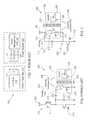
- FIG. 2is a block diagram of a power transfer system using a prior art coil driver based on a class E amplifier.
- FIG. 3is a block diagram of a power transfer system using a coil driver based on a resonant DC-AC converter topology.
- FIG. 4A-4Dare timing waveforms for various values of on times for a switch for a coil driver, according to an embodiment of the present invention.
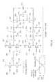
- FIG. 5Ais a block diagram of a feedback controlled coil driver according to an embodiment of the present invention.
- FIG. 5Bis a timing waveform for the output of the ramp generator in FIG. 5A .
- FIG. 6is an exemplary schematic of the inductor switch and sample and hold of FIG. 5A .
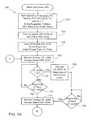
- FIGS. 7A-7Bis a flowchart showing a method for feedback control of a coil driver for inductive power transfer according to an embodiment of the present invention.
- FIG. 3is a block diagram of a power transfer system 300 using a coil driver 310 based on resonant DC-AC converter topology. See N. Mohan, T. Undeland and W. Robbins, Power electronics: converters, applications, and design, John Wiley & Sons, 2003 and also M. Paemel, “High-efficiency transfer for medical implants,” IEEE Solid-State Cir. Mag., vol. 3, pp. 47-59, 2011 for more information on resonant DC-AC converter design.
- Primary coil LP ( 312 ) and discrete capacitor CT ( 314 )form a resonant LC tank circuit for transmitting power to the secondary coil LS ( 322 ) in implant 320 .
- One possible operating frequency FO, for such an inductive linkis at about 120 kHz. See E. Lee, et al., “A biomedical implantable FES battery-powered micro-stimulator,” IEEE Tran. Cir. Syst. I, vol. 56, pp. 2583-2596, December 2009. For higher operating frequencies (e.g., 13.56 MHz), capacitor CT ( 314 ) can be potentially integrated on-chip for further component reduction.
- a feedback loopminimizes the power dissipation on coil driver 310 by controlling the “on time” (TON) of switch MS ( 316 ).
- Coil driver 310is also capable of providing amplitude shift keying (ASK) modulation on the power transfer since, in some applications, data is sent from the external controller to an implant via the same inductive link.
- ASKamplitude shift keying
- primary coil current IL ( 313 )is generated by turning on, at controlled times, switch MS ( 316 ) such that primary coil LP ( 312 ) is energized by supply voltage VLP ( 301 ).
- switch MS ( 316 )When switch MS ( 316 ) is off, primary coil LP ( 312 ) and capacitor CT ( 314 ) are decoupled from ground and will resonate, producing a sinusoidal primary coil current IL ( 313 ) until switch MS ( 316 ) is turned on again in the next cycle, as shown in FIG. 4A .
- the peak to peak value of primary coil current IL given as ILP-Pis maximized by controlling the on time TON ( 404 ), for switch MS ( 316 ) so that switch MS ( 316 ) only allows current flow when the coil driver output voltage VL ( 304 ) across switch MS ( 316 ), reaches exactly 0V and remains essentially 0V during the duration of on time TON ( 404 ).
- the power dissipation by switch MS ( 316 )is minimized and the turn on time TON ( 404 ) will be equal to the optimal on time given as TOP ( 405 ) and the following condition, as shown in equation (1) below, will be satisfied,
- FLC FO1 1 - FO ⁇ TOP ⁇ ( 1 2 + 1 ⁇ ⁇ arctan ⁇ 1 ⁇ ⁇ ⁇ FLC ⁇ TOP ) ( 1 )
- VLMAXVLP ⁇ ( 1 + 1 / sin ⁇ ⁇ ⁇ ) ( 2 )
- FM( 408 ), defined as FO ⁇ LP ⁇ ILP ⁇ P 2 /PLP will be used to measure the effectiveness of generating primary coil current IL, when the on time TON the optimal on time TOP, then FM will be maximized.
- FOfield-to-live
- manual adjustments on primary coil LP, capacitor CT or on time TONare often required to maximize the power transfer to an implant, (See S. Lee, et al., 2011 and R. Sarpeshkar, 2010 cited above).
- the impedance of primary coil LP ( 312 ), and hence, the resonant frequency of primary coil LP ( 312 ) and capacitor CT ( 314 ),may deviate from the nominal value after manual adjustments when primary coil LP ( 312 ) is near any metallic objects or an implant that has large coupling coefficients (KC>0.1) with primary coil LP ( 312 ) (See R. Sarpeshkar, 2010 cited above).
- the present inventionprovides an automatic adjustment scheme to achieve optimal on time TOP for primary coil LP ( 312 ).
- FIG. 4A-4Dare timing waveforms for various values of on times TON ( 404 ) for switch MS ( 516 ) for coil driver 500 .
- FIGS. 4A-4Dshow four timing waveforms: voltage VSW ( 503 ) applied to switch MS ( 516 ), coil current IL ( 513 ) and coil driver output voltage VL ( 504 ) for various values of on time TON ( 404 ) in relation to an optimal on time TOP ( 405 ).
- VSW503
- VSWcoil current IL
- turn on time TON ( 404 )begins at turn on start time TST ( 402 ).
- Voltage VSW ( 503 ) applied to switch MS ( 516 )is a repetitive pulse signal with a frequency equal to the operating frequency FO.
- FIG. 5Ais a block diagram of a feedback controlled coil driver 500 according to an embodiment of the present invention.
- FIG. 5Bis a timing waveform for the output of the ramp generator 552 in FIG. 5A .
- Primary coil LP ( 512 ) and capacitor CT ( 514 )form an LC tank circuit for power transfer to a secondary coil, which is not shown in FIG. 5A .
- a feedback controlled techniqueis used to achieve optimal on time TOP ( 504 ) automatically.
- a sample and hold circuit S/H ( 534 )is used to sample the coil driver output voltage VL ( 504 ) across switch MS ( 516 ) at the instant switch MS ( 516 ) is turned on.
- the feedback loop for controlling MS ( 516 )is to have coil driver output voltage VL ( 504 ) equal to zero when MS ( 516 ) starts to turn on.
- VL ( 504 )is compared to VREF ( 536 ) after it is sampled at the instant when MS ( 516 ) starts to turn on. This comparison drives the on time in the right direction until VL ( 504 ) equals VREF ( 536 ). With VREF equal to zero, VL will be driven to zero in steady state and the optimum on time TON will be achieved.
- the integrator 541 output voltage VIO ( 542 )is used as a threshold for comparator CO 1 ( 550 ).
- On time TON ( 404 )is determined by the output of comparator CO 1 ( 550 ), ramp generator 552 and the value of VIO ( 542 ).
- ramp generator 552begins to produce ramp voltage VRAMP ( 554 ) shown in FIG. 5B .
- comparator CO 1 ( 550 )will signal digital circuit 522 to turn off switch MS ( 516 ) via control signal 556 . Therefore, on time TON ( 404 ) is the time taken from TST ( 402 ) to the instant when comparator CO 1 ( 550 ) causes MS ( 516 ) to turn off.
- Digital circuits 522include a repetitive pulse signal generator to provide a pulse train VSW ( 503 ) to coil driver switch MS ( 516 ) at operating frequency FO.
- Each pulse of pulse train VSW ( 503 )has turn on start time TST ( 402 ) and a pulse width (“on time”) TON ( 404 ) which is controlled by feedback controller 530 via control signal 556 .
- FIG. 5Billustrates the influence of the value of VIO on the switch on time TON.
- the corresponding on timeis TON1 and for a VIO value of VIO2, the corresponding on time is TON2. Since the signal appearing at the output of integrator 541 is greater at VIO2 than at VIO1, the switch on time TON2 will be longer than the on time TON1.
- the slope of the VRAMP ( 554 ) signalis fixed by the ramp generator ( 552 ), but can be adjusted to establish speed of feedback response.
- the maximum value of ramp voltage VRAMP ( 544 ) during any one cycle ( 412 ) of operating frequency FOis less than or equal to the supply voltage of ramp generator 552 .
- sample and hold circuit S/H ( 534 ), integrator 541 , ramp generator 552 and comparator CO 1 ( 550 )may, in combination, be considered a feedback controller for providing a control signal 556 for controlling the on time of switch MS ( 516 ).
- the control signalcomprises the integral of the difference between the sampled output voltage VLS and VREF as influenced by the ramp voltage VRAMP ( 554 ) in comparator CO 1 .
- sampled voltage VLS ( 538 ) and therefore error voltage VERwill be less than 0V as shown in FIG. 4B .
- Integrator 541will drive voltage VIO ( 542 ) to a higher value, resulting in a longer on time TON.
- sampled voltage VLSwill be greater than 0V as shown in FIG. 4C .
- Integrator 541 output voltage VIO ( 542 )will be driven to a lower value resulting in a shorter on time TON.
- the feedback loopmay incorrectly interpret that on time TON is too long and proceed to reduce it further, eventually complete turning off switch MS ( 516 ).
- primary coil LP( 512 ) will be recharged solely by the parasitic diode and coil driver 500 will operate at a frequency different from the operating frequency FO.
- the driverwill have a very low figure of merit FM. This condition can be avoided by ensuring a minimum pulse width for TON and by adding a comparator CO 2 ( 532 ) as shown in FIG. 5A .
- comparator CO 2When the voltage across switch MS ( 516 ), VL is less than 0V, comparator CO 2 ( 532 ) will signal the sample and hold S/H ( 534 ) to sample voltage VL ( 504 ) at the next clock 520 cycle even before turn on start time TST. Hence, the sampled voltage VLS will be less than 0V such that integrator 541 will drive its output voltage VIO ( 542 ) to a higher value leading to a longer on time TON and ultimately, an optimal on time TOP in steady state.
- the power transfer level of coil driver 500can be controlled by adjusting the coil supply voltage VLP ( 501 ) without affecting on time TON since the peak to peak primary coil current ILP-P is directly proportional to supply voltage VLP ( 501 ) according to Eq. (3).
- FIG. 6is a schematic of an exemplary implementation of the inductor switch MS ( 516 ) and sample and hold S/H ( 534 ) of FIG. 5A .
- the VGS's and the VDS's of the MOSFETswill be limited to ⁇ 5V and ⁇ 12V, respectively.
- a MOSFET transistor MC ( 618 )is added in series to switch MS ( 616 ) as shown in FIG. 6 .
- sample voltage VLScan be obtained by sampling VLD ( 609 ), which has a lower voltage swing that is less than VDD. Therefore, the input of the sample and hold S/H ( 534 ) does not need to have high voltage tolerance. Since voltages VL ( 604 ) and VLD ( 609 ) can also go below 0V as shown in FIG. 4B and FIG. 4D , MOSFETs M 1 -M 2 ( 621 , 622 ) are used as a level shifter as well as a buffer to prevent charge leakage from sampling capacitor CS ( 654 ) to VLD ( 609 ) via the parasitic NPN associated with switch S 1 ( 641 ).
- a similar circuit arrangementis used for the reference voltage input VREF ( 636 ) to match the VLD ( 609 ) voltage input.
- the charges on sampling capacitors CS ( 654 )redistribute to the holding capacitors CH ( 656 ).
- the voltage difference between holding capacitors CH ( 656 )represents the voltage difference between VLD ( 609 ) and VREF ( 636 ), or VER ( 612 ).
- this operationalso introduces an extra pole in the feedback loop. This extra pole is compensated using a switched capacitor CD ( 664 ), which allows better control on the DC gain as well as the pole location of the sample and hold S/H ( 634 ) for achieving overall stability of coil driver 500 .
- Switches S 1 -S 7 inside sample and hold S/H ( 634 )are controlled by two non-overlapping clock signals—S ( 650 ) and T ( 652 ).
- Signal Scontrols switches S 1 , S 3 , S 5 and S 6 .
- Signal Tcontrols switches S 2 , S 4 and S 7 .
- transconductor GM540
- comparators CO 1550
- CO 2532
- coil driver 500is also designed for sending data to an implant using ASK modulation.
- a low modulation index in the range between 5% and 25%can be used for such implants.
- ASK modulation on primary coil current IL ( 513 )can be achieved by modulating the coil supply VLP ( 501 ) according to the digital input DATA ( 524 ), a complicated hybrid amplifier for fast settling can be required to drive supply voltage VLP ( 501 ) (See, for example, Y. Wu and P. Mok, “ A two - phase switching hybrid supply modulator for polar transmitters with 9% efficiency improvement,” ISSCC Dig. Tech. papers, pp. 196-197, 2010).
- RONon-resistance
- a technique for data transfer utilizing the tank circuitis to supplement the switch MS ( 516 ) with a plurality of switches, wherein the number of switches in the plurality is controlled by or is a function of the digital DATA Input signal which may be modulated by ASK for data transfer.
- FIGS. 7A-7Bis a flowchart 700 showing a method for feedback control of a coil driver, such as coil driver 500 in FIG. 5A , for inductive power transfer according to an embodiment of the present invention.
- a repetitive pulse signal at the operating frequency FOis generated having a frequency of the clock 520 divided by N. Accordingly, N pulses of the clock 520 will occur between consecutive pulses of FO.
- Integrator voltage VIO ( 542 )is set to an initial value.
- Flowproceeds to block 704 , where switch MS ( 516 ) is turned on at turn on start time TST, which is the time at which the leading edge of switch voltage VSW ( 503 ) occurs.
- Switch voltage VSW ( 503 )is the pulse signal generated in block 702 .
- Flowproceeds to block 706 .
- switch MS ( 516 )is turned off according to an initial preset turn on time.
- Flowproceeds to block 708 where the feedback controlled coil driver protocol commences.
- the coil driver output voltage VL ( 504 ) across switch MS ( 516 )is sampled.
- Flowproceeds to block 710 .
- the voltage VL ( 504 )is examined to determine whether it is less than 0 volts. If VL is equal to or greater than 0 volts, flow proceeds to block 712 . If VL is less than 0 volts, flow proceeds to block 730 .
- Block 712a test for the beginning of the next consecutive turn on start time TST occurs. If the next consecutive turn on start time TST has not occurred, then flow returns to block 710 .
- Blocks 710 and 712comprise a continuous or repetitive loop until the next turn on start time TST occurs.
- coil driver output voltage VL ( 504 )is sampled at the beginning of the next clock 520 cycle. In other words, VL is sampled at the occurrence of the next pulse in the pulse train defining clock 520 . No more than N clock pulses will occur before a TST occurs.
- Flowproceeds to block 732 , where a test for the beginning of the next turn on start time TST occurs. If the next turn on start time TST has not taken place, then flow returns to block 732 . If the next turn on start time TST has occurred, then flow proceeds to block 714 , where voltage VL ( 504 ) is sampled and flow proceeds to block 716 .
- switch MS( 516 ) is turned on, ramp generator 552 starts to generate VRAMP ( 554 ).
- Flowproceeds to block 720 .
- step 720the output of ramp generator 552 VRAMP ( 554 ) is examined to determine whether it is greater than integrator voltage VIO. If VRAMP is less than or equal to VIO, then flow proceeds to block 734 , where switch MS ( 516 ) is kept on and flow returns to block 720 . If VRAMP is greater than VIO, then flow proceeds to block 722 .
- the turn on time of switch MS ( 516 )is tested to see if it is greater than a preset minimum turn on time. If the turn on time of switch MS ( 516 ) is not greater than the preset minimum turn on time, then flow proceeds to block 736 , where switch MS ( 516 ) is kept on and flow proceeds back to block 722 . If the turn on time of switch MS ( 516 ) is greater than a preset minimum turn on time, then flow proceeds to block 724 , where switch MS ( 516 ) is turned off and flow proceeds to block 726 .
- the blocks 722 and 724are precautionary in nature to compensate for a situation when TON may be considered too short, as shown in FIG. 4D , for proper circuit operation. However, with comparator ( 532 ) and the associated circuits operating as contemplated, the on time TON will be adjusted correctly and blocks 722 and 724 may be eliminated.
- a testoccurs to determine if coil driver 500 should be turned off. If coil driver 500 is to be turned off, then method 700 ends. If coil driver 500 is not to be turned off, then flow returns to block 708 .
Landscapes
- Engineering & Computer Science (AREA)
- Power Engineering (AREA)
- Computer Networks & Wireless Communication (AREA)
- Dc-Dc Converters (AREA)
- Amplifiers (AREA)
- Inverter Devices (AREA)
- Control Of Electrical Variables (AREA)
Abstract
Description
This application is a continuation of International Appl. No. PCT/US2013/057592, filed Aug. 30, 2013, which claims the benefit of U.S. Provisional Application No. 61/695,815 entitled “FEEDBACK CONTROLLED COIL DRIVER FOR INDUCTIVE POWER TRANSFER,” filed on Aug. 31, 2012, the entirety of which is hereby incorporated by reference herein.
Inductive power transfer or transmission is frequently used to deliver power wirelessly to portable electronic devices. Wireless power transfer is used in a variety of applications, such as, for recharging the batteries in portable devices, such as smart phones, tablets and laptops. Such power transfer systems are also used to transmit power transcutaneously, i.e., through the skin, to implanted medical devices, to either power an implant directly or to recharge the implant's battery.
As shown inFIG. 1 , a conventionalpower transfer system 100 typically includes acoil driver 114 driving a primary coil LP (112), which inductively couples and powers secondary coil, LS (122) located insideelectronic device 120. Various transcutaneous power transfer systems are described in: W. Loke, et al., “A 0.5V sub-mW wireless magnetic tracking transponder for radiation therapy,” Sym. on VLSI Cir., pp. 172-173, 2011; Y. Liao, et al., “A 3 μW wireless powered CMOS glucose sensor for an active contact lens,” ISSCC Dig. Tech. papers, pp. 38-39, 2011 and S. Lee, et al., “A low-power bidirectional telemetry device with a near-field charging feature for a cardiac microstimulator,” IEEE Tran. Bio. Cir. Syst., vol. 5, pp. 357-367, August, 2011. Although some implants are designed to obtain power directly from the batteries within the implants, those batteries that are rechargeable still have to be recharged wirelessly by an external power transmitter. See E. Lee, et al., “A biomedical implantable FES battery-powered micro-stimulator,” IEEE Tran. Cir. Syst. I, vol. 56, pp. 2583-2596, December 2009. In recent developments, many efforts have been devoted to improve the power reception and the power management within the implants. See, for example, H. Lee and M. Ghovanloo, “Fully integrated power efficient AC-to-DC converter design in inductively powered biomedical applications,” Proc. of IEEE 2011 CICC, paper 8.7, 2011. However, the coil driver in an external transmitter still requires a lot of discrete components. See the article by S. Lee, et al., 2011 cited above and also G. Kendir, et al., “An optimal design methodology for inductive power link with class-E amplifier,” IEEE Tran. Cir. Syst. I, vol. 52, pp. 857-866, May, 2005.
Class Eamplifier type systems 210 as shown inFIG. 2 are commonly used in coil driver designs, See S. Lee, et al., 2011 and G. Kendir, et al., 2005 cited above. In addition to discrete capacitors CT1 (213) and CT2 (215), a bulky RF choke LC (211) is also required in this circuit topology. Since a power transmitter is normally part of a patient's external controller for an implantedmedical device 220, it is important for the external controller to be small and lightweight. Therefore, a coil driver for such a wireless power transfer system should use a minimal number of discrete components to achieve a small size and should have low power consumption such that only a small battery is required.
The invention deals with a design for a feedback controlled coil driver that achieves an optimum coil driver switch “on time”. The coil is part of an LC tank circuit and the optimum coil driver switch “on time” is achievable for different operating frequencies without the need for adjusting the values of the inductance and capacitance of the LC tank circuit. The optimum coil driver switch “on time” further results in a maximized value of the ratio of the square of the peak to peak coil current to the power delivered by a LC tank circuit power supply.
The optimum coil driver switch “on time” is obtained by switchably coupling the LC tank circuit between a power supply and ground at controlled times. A sample and hold circuit monitors the LC tank circuit output voltage and an integrator circuit integrates the difference between the output voltage and a prescribed reference voltage which is typically set to zero volts. One of many unique attributes of the present invention is that a ramp voltage is generated at the time the LC tank circuit is coupled to ground which is then compared to the output of the integrator circuit. The coil driver switch decouples the LC tank circuit from ground when the value of the ramp voltage exceeds the value of the integrated difference voltage.
A repetitive pulse signal generator provides a pulse train to the coil driver switch at a predetermined frequency. Each pulse of the pulse train has a start time and a pulse width (“on time”) which is controlled by the feedback loop as described above which causes the “on time ” to be optimized with the identified benefits and advantages.
As will be discussed with respect toFIGS. 4A-4D and 5A-5B , a feedback loop minimizes the power dissipation oncoil driver 310 by controlling the “on time” (TON) of switch MS (316).Coil driver 310 is also capable of providing amplitude shift keying (ASK) modulation on the power transfer since, in some applications, data is sent from the external controller to an implant via the same inductive link. See, for example S. Lee, et al., 2011 cited above and also R. Sarpeshkar, Ultra low power bioelectronics: fundamentals, biomedical applications, and bio-inspired systems, Cambridge University Press, 2010.
The operating frequency FO ofcoil driver 310 is derived from an input clock frequency, FCLOCK, where, for the current application, FCLOCK=20×FO. For proper operation ofcoil driver 310, capacitor CT (314) is selected such that the resonant frequency of primary coil LP (312) and CT (314) is FLC=½π/(LP×CT)0.5is greater than FO, (See M.
Paemel, “High-efficiency transmission for medical implants,” IEEE Solid-State Cir. Mag., vol. 3, pp. 47-59, 2011). Due to the physical sizes and the location constraints of the coils in an implant and an external controller, the coupling coefficient KC (306) and the Q factors of the coils are relatively small in these types of systems. Hence, the power efficiency of the inductive coupling is also low.
To maximize the power transfer to secondary coil LS (322), the current on primary coil LP (312) inFIG. 3 , given as primary coil current IL (313), must be maximized for a given power delivery from the primary coil supply voltage VLP (301), (See R. Sarpeshkar, 2012 cited above). Primary coil current IL (313) is generated by turning on, at controlled times, switch MS (316) such that primary coil LP (312) is energized by supply voltage VLP (301). When switch MS (316) is off, primary coil LP (312) and capacitor CT (314) are decoupled from ground and will resonate, producing a sinusoidal primary coil current IL (313) until switch MS (316) is turned on again in the next cycle, as shown inFIG. 4A . For a given power PLP, from supply voltage VLP (316), the peak to peak value of primary coil current IL given as ILP-P is maximized by controlling the on time TON (404), for switch MS (316) so that switch MS (316) only allows current flow when the coil driver output voltage VL (304) across switch MS (316), reaches exactly 0V and remains essentially 0V during the duration of on time TON (404). In this case, the power dissipation by switch MS (316) is minimized and the turn on time TON (404) will be equal to the optimal on time given as TOP (405) and the following condition, as shown in equation (1) below, will be satisfied,
The maximum value of coil driver output voltage VL (304) across switch MS (316), VLMAX, and the peak to peak primary coil current ILP-P can be written as:
where θ=arctan [2/TOP·(CT·LP)0.5].
A figure of merit, FM (408), defined as FO·LP·ILP−P2/PLP will be used to measure the effectiveness of generating primary coil current IL, when the on time TON the optimal on time TOP, then FM will be maximized. For a given operating frequency FO, manual adjustments on primary coil LP, capacitor CT or on time TON are often required to maximize the power transfer to an implant, (See S. Lee, et al., 2011 and R. Sarpeshkar, 2010 cited above). The impedance of primary coil LP (312), and hence, the resonant frequency of primary coil LP (312) and capacitor CT (314), may deviate from the nominal value after manual adjustments when primary coil LP (312) is near any metallic objects or an implant that has large coupling coefficients (KC>0.1) with primary coil LP (312) (See R. Sarpeshkar, 2010 cited above). The present invention provides an automatic adjustment scheme to achieve optimal on time TOP for primary coil LP (312).
For on time TON greater than optimal on time TOP, sampled voltage VLS will be greater than 0V as shown inFIG. 4C .Integrator 541 output voltage VIO (542) will be driven to a lower value resulting in a shorter on time TON. In steady state, the feedback loop will drive sampled voltage VLS (538) to the value of the reference voltage VREF (536) and as a result, the error voltage VER=0V and voltage VIO (542) will remain constant. At that point, TON (404) is at its optimal value and equal to TOP (405) for VREF=0V. Even if the value of primary coil LP (512) deviates from the nominal value due to a nearby metallic object, the feedback loop will adjust TON (404) according to sampled voltage VLS (538) until VLS=0V and the optimal on time TOP (405) is achieved. Resistor RI (544) and capacitor CR (548) are added to the feedback loop for respective stability compensation and ripple reduction on voltage VIO (542).
In cases where on time TON (404) is too short during power up, the coil driver output voltage VL (504) across switch MS (516) will go negative and turn on the parasitic diode of switch MS (516) before switch MS (516) turns on at turn on start time TST as shown inFIG. 4D . Primary coil LP (512) will be charged through the parasitic diode of switch MS (516) and coil driver output voltage VL (504) may even begin to increase before switch MS (516) turns on at turn on start time TST, resulting in a positive sampled voltage VLS (538). The feedback loop may incorrectly interpret that on time TON is too long and proceed to reduce it further, eventually complete turning off switch MS (516). As a consequence, primary coil LP (512) will be recharged solely by the parasitic diode andcoil driver 500 will operate at a frequency different from the operating frequency FO. In addition, the driver will have a very low figure of merit FM. This condition can be avoided by ensuring a minimum pulse width for TON and by adding a comparator CO2 (532) as shown inFIG. 5A .
When the voltage across switch MS (516), VL is less than 0V, comparator CO2 (532) will signal the sample and hold S/H (534) to sample voltage VL (504) at thenext clock 520 cycle even before turn on start time TST. Hence, the sampled voltage VLS will be less than 0V such thatintegrator 541 will drive its output voltage VIO (542) to a higher value leading to a longer on time TON and ultimately, an optimal on time TOP in steady state.
The power transfer level ofcoil driver 500 can be controlled by adjusting the coil supply voltage VLP (501) without affecting on time TON since the peak to peak primary coil current ILP-P is directly proportional to supply voltage VLP (501) according to Eq. (3).
Instead of sampling coil driver output voltage VL (604) directly, sample voltage VLS can be obtained by sampling VLD (609), which has a lower voltage swing that is less than VDD. Therefore, the input of the sample and hold S/H (534) does not need to have high voltage tolerance. Since voltages VL (604) and VLD (609) can also go below 0V as shown inFIG. 4B andFIG. 4D , MOSFETs M1-M2 (621,622) are used as a level shifter as well as a buffer to prevent charge leakage from sampling capacitor CS (654) to VLD (609) via the parasitic NPN associated with switch S1 (641). A similar circuit arrangement is used for the reference voltage input VREF (636) to match the VLD (609) voltage input. After the voltage VL (604) is sampled, the charges on sampling capacitors CS (654) redistribute to the holding capacitors CH (656). The voltage difference between holding capacitors CH (656) represents the voltage difference between VLD (609) and VREF (636), or VER (612). However, this operation also introduces an extra pole in the feedback loop. This extra pole is compensated using a switched capacitor CD (664), which allows better control on the DC gain as well as the pole location of the sample and hold S/H (634) for achieving overall stability ofcoil driver 500. Switches S1-S7 inside sample and hold S/H (634) are controlled by two non-overlapping clock signals—S (650) and T (652). Signal S controls switches S1, S3, S5 and S6. Signal T controls switches S2, S4 and S7. For the other circuits including transconductor GM (540), comparators CO1 (550) and CO2 (532), conventional circuit design techniques can be used.
As discussed previously,coil driver 500 is also designed for sending data to an implant using ASK modulation. A low modulation index in the range between 5% and 25% can be used for such implants. Although ASK modulation on primary coil current IL (513) can be achieved by modulating the coil supply VLP (501) according to the digital input DATA (524), a complicated hybrid amplifier for fast settling can be required to drive supply voltage VLP (501) (See, for example, Y. Wu and P. Mok, “A two-phase switching hybrid supply modulator for polar transmitters with9%efficiency improvement,”ISSCC Dig. Tech. papers, pp. 196-197, 2010).
A simpler scheme that does not require any additional discrete components to achieve ASK modulation can be used. It is based on changing the size of switch MS (516) according to digital input DATA. For DATA=1, the size of switch MS (516) remains nominal and the amplitude of primary coil current IL is the amplitude during the normal power transfer operation discussed above. For DATA=0, primary coil current IL (513) is modulated to have a lower amplitude by reducing the size of switch MS (516) for a higher on-resistance (RON), limiting the current flow from supply voltage VLP (501) to primary coil LP (512). However, the voltage across switch MS (516) is non-zero in this case even when switch MS (516) is on. As a result, the power dissipation is higher than the optimal value achieved during the normal power transfer operation. Nevertheless, sending data to an implant may not occur frequently, depending on the application. A technique for data transfer utilizing the tank circuit is to supplement the switch MS (516) with a plurality of switches, wherein the number of switches in the plurality is controlled by or is a function of the digital DATA Input signal which may be modulated by ASK for data transfer.
Inblock 706, switch MS (516) is turned off according to an initial preset turn on time. Flow proceeds to block708 where the feedback controlled coil driver protocol commences. Inblock 708, the coil driver output voltage VL (504) across switch MS (516) is sampled. Flow proceeds to block710. Inblock 710, the voltage VL (504) is examined to determine whether it is less than 0 volts. If VL is equal to or greater than 0 volts, flow proceeds to block712. If VL is less than 0 volts, flow proceeds to block730.
Inblock 712, a test for the beginning of the next consecutive turn on start time TST occurs. If the next consecutive turn on start time TST has not occurred, then flow returns to block710.Blocks
Inblock 730, coil driver output voltage VL (504) is sampled at the beginning of thenext clock 520 cycle. In other words, VL is sampled at the occurrence of the next pulse in the pulsetrain defining clock 520. No more than N clock pulses will occur before a TST occurs. Flow proceeds to block732, where a test for the beginning of the next turn on start time TST occurs. If the next turn on start time TST has not taken place, then flow returns to block732. If the next turn on start time TST has occurred, then flow proceeds to block714, where voltage VL (504) is sampled and flow proceeds to block716.
Inblock 716, switch MS (516) is turned on,ramp generator 552 starts to generate VRAMP (554). Flow proceeds to block718, where integrator voltage VIO (542) is updated based on the equation VIO (new)=VIO (old)+C×VL, where C is a constant. Flow proceeds to block720.
Inblock 720, the output oframp generator 552 VRAMP (554) is examined to determine whether it is greater than integrator voltage VIO. If VRAMP is less than or equal to VIO, then flow proceeds to block734, where switch MS (516) is kept on and flow returns to block720. If VRAMP is greater than VIO, then flow proceeds to block722.
Inblock 722, the turn on time of switch MS (516) is tested to see if it is greater than a preset minimum turn on time. If the turn on time of switch MS (516) is not greater than the preset minimum turn on time, then flow proceeds to block736, where switch MS (516) is kept on and flow proceeds back to block722. If the turn on time of switch MS (516) is greater than a preset minimum turn on time, then flow proceeds to block724, where switch MS (516) is turned off and flow proceeds to block726. Theblocks FIG. 4D , for proper circuit operation. However, with comparator (532) and the associated circuits operating as contemplated, the on time TON will be adjusted correctly and blocks722 and724 may be eliminated.
Inblock 726, a test occurs to determine ifcoil driver 500 should be turned off. Ifcoil driver 500 is to be turned off, thenmethod 700 ends. Ifcoil driver 500 is not to be turned off, then flow returns to block708.
Although the preceding description describes various embodiments of the system, the invention is not limited to such embodiments, but rather covers all modifications, alternatives, and equivalents that fall within the spirit and scope of the invention. Since many embodiments of the invention can be made without departing from the spirit and scope of the invention, the invention resides in the claims hereinafter appended.
Claims (20)
1. A feedback controlled coil driver (500) comprising:
an LC tank circuit (512,514);
a direct current power source (501) coupled to the LC tank circuit;
a switch (516) interconnected between the LC tank circuit and ground to
switchably couple the LC tank circuit between the power source and ground when the switch is turned on, wherein the interconnection between the LC tank circuit and the switch provides a coil driver output voltage VL (504);
a sample and hold circuit (534) arranged to monitor the VL;
an integrator circuit (541) configured to provide a voltage VIO (542) equal to the integral over time of a difference between the sampled VL and a prescribed reference voltage (536);
a voltage ramp generator (552) arranged to provide a ramp voltage (554) at such time when the switch couples the LC tank circuit to ground;
a first comparator (550) arranged to compare VIO to the ramp voltage; and
a switch driver (525) coupled to the first comparator and arranged to turn the switch off when the ramp voltage exceeds VIO.
2. The feedback controlled coil driver ofclaim 1 wherein the sample and hold circuit monitors and holds the VL at an instant TON (404) when the switch is turned on.
3. The feedback controlled coil driver ofclaim 2 wherein the voltage ramp generator commences generating a ramp voltage at the instant when the switch is turned on.
4. The feedback controlled coil driver ofclaim 3 further comprising a first repetitive pulse signal generator (522) coupled to the switch driver and configured to provide a repetitive pulse signal (503) at a first prescribed frequency (FO), wherein the pulses each have a turn on start time (TST) and wherein the switch driver causes the switch to turn on at each consecutive TST.
5. The feedback controlled coil driver ofclaim 4 wherein the prescribed reference voltage is zero volts.
6. The feedback controlled coil driver ofclaim 4 further comprising a second comparator (556) arranged to compare the VL to ground and configured to cause the sample and hold circuit to sample and hold the VL when the VL is less than ground.
7. The feedback controlled coil driver ofclaim 6 further comprising a second repetitive pulse signal generator configured to provide a second repetitive pulse signal (520) at a second prescribed frequency being greater than the first prescribed frequency and wherein the second comparator causes the sample and hold circuit to sample and hold the VL at an occurrence of a selected pulse in the second repetitive pulse signal.
8. The feedback controlled coil driver ofclaim 7 wherein the selected pulse is defined between consecutive TST's at the instant when the VL is less than zero.
9. The feedback controlled coil driver ofclaim 8 wherein the switch comprises a plurality of switches wherein the number of switches in the plurality is a function of a data input signal modulated by amplitude shift keying for data transfer utilizing the tank circuit.
10. A method of driving a coil in an LC circuit comprising the steps of:
providing an LC tank circuit (512,514) configured to generate an output voltage (VL);
switching the LC tank circuit between a power source (501) and ground at controlled times;
monitoring the VL and integrating over time the difference between the VL and a preselected reference voltage, to provide an integrated difference voltage (VIO (542));
providing a ramp voltage (554) commencing when the LC tank circuit is connected between the power source and ground; and
disconnecting the LC tank circuit from ground when the ramp voltage exceeds VIO.
11. The method ofclaim 10 further comprising the step of providing a first repetitive pulse signal at a first frequency (FO), wherein the pulses each have a turn on start time (TST) and a pulse duration TON (404).
12. The method ofclaim 11 further comprising the step of connecting the LC tank circuit to ground at each consecutive TST.
13. The method ofclaim 12 wherein the step of monitoring further comprises the step of monitoring and holding the VL at the instant when the LC tank circuit is connected to ground.
14. The method ofclaim 13 further comprising the step of monitoring and holding the VL when the VL is less than ground.
15. The method ofclaim 14 further comprising the steps of:
providing a second repetitive pulse signal (520) having a frequency greater than the frequency of the first repetitive pulse signal; and
monitoring and holding the VL during a pulse in the second repetitive pulse signal occurring between consecutive TST's at an instant VL is less than zero.
16. A feedback controlled coil driver circuit comprising:
an LC tank circuit (512,514) having an output voltage (504);
a switch (516) configured to switchably couple the LC tank circuit between a power source (501) and ground;
a repetitive pulse signal generator (522) coupled to the switch, a pulse signal (503) generated by the pulse signal generator, having a controllable on time (404), wherein during such on time, the switch couples the LC tank circuit between the power source and ground; and
a feedback controller (530) configured to provide a control signal (556) to control the on time of the pulse signal, the control signal comprising an integral over time, of a difference between the output voltage and a reference voltage (536) as influenced by a preselected ramp voltage (554).
17. The coil driver circuit ofclaim 16 , wherein the feedback controller comprises a sample and hold circuit (534) configured to sample and hold the value of a sampled output voltage (538) at the instant when the switch is turned on; and an integrator circuit (541) configured to integrate the difference between the sampled output voltage and a preselected reference voltage to thereby provide an integrator circuit output voltage542.
18. The coil driver circuit ofclaim 17 , wherein the feedback controller further comprises a voltage ramp generator (552) arranged to commence providing a ramp voltage (554) when the switch couples the LC tank circuit between the power source and ground; and a first comparator (550) arranged to compare the integrator circuit output voltage and the ramp voltage for providing the control signal and wherein the control signal influences the pulse signal on time to cause the LC tank circuit to be decoupled between the power source and ground when the ramp voltage exceeds the integrator circuit output voltage.
19. The coil driver circuit ofclaim 18 , wherein the feedback controller further comprises a second comparator (532) arranged to compare the output voltage to ground and configured to cause the sample and hold circuit to sample and hold the output voltage when the output voltage is less than ground.
20. The coil driver circuit ofclaim 19 , wherein the reference voltage is zero volts.
Priority Applications (2)
| Application Number | Priority Date | Filing Date | Title |
|---|---|---|---|
| US14/631,627US9728981B2 (en) | 2012-08-31 | 2015-02-25 | Feedback controlled coil driver for inductive power transfer |
| US14/698,729US9837831B2 (en) | 2012-08-31 | 2015-04-28 | Class E coil driver with switched capacitor ASK modulation |
Applications Claiming Priority (3)
| Application Number | Priority Date | Filing Date | Title |
|---|---|---|---|
| US201261695815P | 2012-08-31 | 2012-08-31 | |
| PCT/US2013/057592WO2014036449A1 (en) | 2012-08-31 | 2013-08-30 | Feedback controlled coil driver for inductive power transfer |
| US14/631,627US9728981B2 (en) | 2012-08-31 | 2015-02-25 | Feedback controlled coil driver for inductive power transfer |
Related Parent Applications (1)
| Application Number | Title | Priority Date | Filing Date |
|---|---|---|---|
| PCT/US2013/057592ContinuationWO2014036449A1 (en) | 2012-08-31 | 2013-08-30 | Feedback controlled coil driver for inductive power transfer |
Related Child Applications (1)
| Application Number | Title | Priority Date | Filing Date |
|---|---|---|---|
| US14/698,729Continuation-In-PartUS9837831B2 (en) | 2012-08-31 | 2015-04-28 | Class E coil driver with switched capacitor ASK modulation |
Publications (2)
| Publication Number | Publication Date |
|---|---|
| US20150171637A1 US20150171637A1 (en) | 2015-06-18 |
| US9728981B2true US9728981B2 (en) | 2017-08-08 |
Family
ID=49182516
Family Applications (1)
| Application Number | Title | Priority Date | Filing Date |
|---|---|---|---|
| US14/631,627Active2034-07-15US9728981B2 (en) | 2012-08-31 | 2015-02-25 | Feedback controlled coil driver for inductive power transfer |
Country Status (7)
| Country | Link |
|---|---|
| US (1) | US9728981B2 (en) |
| EP (1) | EP2891239B1 (en) |
| JP (1) | JP6062556B2 (en) |
| CN (1) | CN104662787B (en) |
| AU (1) | AU2013308541B2 (en) |
| CA (1) | CA2882974C (en) |
| WO (1) | WO2014036449A1 (en) |
Cited By (12)
| Publication number | Priority date | Publication date | Assignee | Title |
|---|---|---|---|---|
| US20190245523A1 (en)* | 2018-02-05 | 2019-08-08 | Spy Eye, Llc | Adaptive Tuning of a Contact Lens |
| US10505394B2 (en) | 2018-04-21 | 2019-12-10 | Tectus Corporation | Power generation necklaces that mitigate energy absorption in the human body |
| US10529107B1 (en) | 2018-09-11 | 2020-01-07 | Tectus Corporation | Projector alignment in a contact lens |
| US10644543B1 (en) | 2018-12-20 | 2020-05-05 | Tectus Corporation | Eye-mounted display system including a head wearable object |
| US10649233B2 (en) | 2016-11-28 | 2020-05-12 | Tectus Corporation | Unobtrusive eye mounted display |
| US10790700B2 (en) | 2018-05-18 | 2020-09-29 | Tectus Corporation | Power generation necklaces with field shaping systems |
| US10838239B2 (en) | 2018-04-30 | 2020-11-17 | Tectus Corporation | Multi-coil field generation in an electronic contact lens system |
| US10838232B2 (en) | 2018-11-26 | 2020-11-17 | Tectus Corporation | Eye-mounted displays including embedded solenoids |
| US10845621B1 (en) | 2019-08-02 | 2020-11-24 | Tectus Corporation | Headgear providing inductive coupling to a contact lens, with controller |
| US10895762B2 (en) | 2018-04-30 | 2021-01-19 | Tectus Corporation | Multi-coil field generation in an electronic contact lens system |
| US11137622B2 (en) | 2018-07-15 | 2021-10-05 | Tectus Corporation | Eye-mounted displays including embedded conductive coils |
| US11730947B2 (en) | 2012-12-07 | 2023-08-22 | Medtronic, Inc. | Minimally invasive implantable neurostimulation system |
Families Citing this family (9)
| Publication number | Priority date | Publication date | Assignee | Title |
|---|---|---|---|---|
| CA2882974C (en)* | 2012-08-31 | 2018-10-23 | Alfred E. Mann Foundation For Scientific Research | Feedback controlled coil driver for inductive power transfer |
| US9825553B2 (en)* | 2014-04-17 | 2017-11-21 | Linear Technology Corporation | Voltage regulation in resonant power wireless receiver |
| DE102015112098A1 (en) | 2014-07-25 | 2016-01-28 | Minnetronix, Inc. | Coil parameters and control |
| DE102015112097A1 (en) | 2014-07-25 | 2016-01-28 | Minnetronix, Inc. | power scale |
| US10342908B2 (en) | 2015-01-14 | 2019-07-09 | Minnetronix, Inc. | Distributed transformer |
| DE102016100534A1 (en) | 2015-01-16 | 2016-07-21 | Vlad BLUVSHTEIN | Data transmission in a transcutaneous energy transmission system |
| US10193395B2 (en) | 2015-04-14 | 2019-01-29 | Minnetronix, Inc. | Repeater resonator |
| US10516284B2 (en) | 2016-09-15 | 2019-12-24 | Qualcomm Incorporated | Voltage controlled charge pump and battery charger |
| US11602627B2 (en) | 2018-03-20 | 2023-03-14 | Second Heart Assist, Inc. | Circulatory assist pump |
Citations (229)
| Publication number | Priority date | Publication date | Assignee | Title |
|---|---|---|---|---|
| US3646940A (en) | 1969-07-15 | 1972-03-07 | Univ Minnesota | Implantable electronic stimulator electrode and method |
| US3942535A (en) | 1973-09-27 | 1976-03-09 | G. D. Searle & Co. | Rechargeable tissue stimulating system |
| US4019518A (en) | 1975-08-11 | 1977-04-26 | Medtronic, Inc. | Electrical stimulation system |
| US4044774A (en) | 1976-02-23 | 1977-08-30 | Medtronic, Inc. | Percutaneously inserted spinal cord stimulation lead |
| US4082097A (en) | 1976-05-20 | 1978-04-04 | Pacesetter Systems Inc. | Multimode recharging system for living tissue stimulators |
| US4340062A (en) | 1978-11-06 | 1982-07-20 | Medtronic, Inc. | Body stimulator having selectable stimulation energy levels |
| US4468723A (en) | 1981-04-24 | 1984-08-28 | Hewlett-Packard Company | Magnetically regulated power supply |
| US4558702A (en) | 1983-01-21 | 1985-12-17 | Cordis Corporation | Cardiac pacer having input/output circuit programmable for use with unipolar and bipolar pacer leads |
| US4673867A (en) | 1986-06-30 | 1987-06-16 | Motorola, Inc. | Current mirror circuit and method for providing zero temperature coefficient trimmable current ratios |
| US4744371A (en) | 1987-04-27 | 1988-05-17 | Cordis Leads, Inc. | Multi-conductor lead assembly for temporary use |
| US5143089A (en) | 1989-05-03 | 1992-09-01 | Eckhard Alt | Assembly and method of communicating electrical signals between electrical therapeutic systems and body tissue |
| US5488552A (en) | 1992-10-07 | 1996-01-30 | Hiroshi Sakamoto | Inverter power supply |
| US5690693A (en) | 1995-06-07 | 1997-11-25 | Sulzer Intermedics Inc. | Transcutaneous energy transmission circuit for implantable medical device |
| US5702428A (en) | 1992-05-23 | 1997-12-30 | Axelgaard Manufacturing Company, Ltd. | Electrical stimulation for treatment of incontinence and other neuro-muscular disorders |
| US5702431A (en) | 1995-06-07 | 1997-12-30 | Sulzer Intermedics Inc. | Enhanced transcutaneous recharging system for battery powered implantable medical device |
| US5735887A (en) | 1996-12-10 | 1998-04-07 | Exonix Corporation | Closed-loop, RF-coupled implanted medical device |
| US5741316A (en) | 1996-12-02 | 1998-04-21 | Light Sciences Limited Partnership | Electromagnetic coil configurations for power transmission through tissue |
| US5877472A (en) | 1996-02-22 | 1999-03-02 | Pacesetter, Inc. | System for laser-welding components of an implantable device |
| US5876423A (en) | 1996-06-04 | 1999-03-02 | Biotronik Mess- Und Therapiegeraete Gmbh & Co. Ingenieurbuero Berlin | Implantable stimulator with terminal voltage control of a depletable voltage source |
| US6027456A (en) | 1998-07-10 | 2000-02-22 | Advanced Neuromodulation Systems, Inc. | Apparatus and method for positioning spinal cord stimulation leads |
| US6035237A (en) | 1995-05-23 | 2000-03-07 | Alfred E. Mann Foundation | Implantable stimulator that prevents DC current flow without the use of discrete output coupling capacitors |
| US6055456A (en) | 1999-04-29 | 2000-04-25 | Medtronic, Inc. | Single and multi-polar implantable lead for sacral nerve electrical stimulation |
| US6057513A (en) | 1997-01-29 | 2000-05-02 | Ngk Insulators, Ltd. | Joint structure of metal member and ceramic member and method of producing the same |
| US6067474A (en) | 1997-08-01 | 2000-05-23 | Advanced Bionics Corporation | Implantable device with improved battery recharging and powering configuration |
| US6076017A (en) | 1997-04-30 | 2000-06-13 | Medtronic, Inc. | Method of centerless ground finishing of feedthrough pins for an implantable medical device |
| WO2000056677A1 (en) | 1999-03-24 | 2000-09-28 | Alfred E. Mann Foundation | Method and apparatus of a strong metal-ceramic braze bond |
| WO2000066221A1 (en) | 1999-05-03 | 2000-11-09 | Abiomed, Inc. | Electromagnetic field source with detection of position of secondary coil in relation to multiple primary coils |
| US6164284A (en) | 1997-02-26 | 2000-12-26 | Schulman; Joseph H. | System of implantable devices for monitoring and/or affecting body parameters |
| US6172556B1 (en) | 1999-03-04 | 2001-01-09 | Intersil Corporation, Inc. | Feedback-controlled low voltage current sink/source |
| US6178353B1 (en) | 1998-07-27 | 2001-01-23 | Advanced Bionics Corporation | Laminated magnet keeper for implant device |
| US6185452B1 (en) | 1997-02-26 | 2001-02-06 | Joseph H. Schulman | Battery-powered patient implantable device |
| US6191365B1 (en) | 1997-05-02 | 2001-02-20 | General Science And Technology Corp | Medical devices incorporating at least one element made from a plurality of twisted and drawn wires |
| US6208894B1 (en) | 1997-02-26 | 2001-03-27 | Alfred E. Mann Foundation For Scientific Research And Advanced Bionics | System of implantable devices for monitoring and/or affecting body parameters |
| US6212431B1 (en) | 1998-09-08 | 2001-04-03 | Advanced Bionics Corporation | Power transfer circuit for implanted devices |
| US6221513B1 (en) | 1998-05-12 | 2001-04-24 | Pacific Coast Technologies, Inc. | Methods for hermetically sealing ceramic to metallic surfaces and assemblies incorporating such seals |
| US6246911B1 (en) | 1999-02-08 | 2001-06-12 | Peter Seligman | Cochlear implants with offset coils for transmission of radio frequency links |
| US6249703B1 (en) | 1994-07-08 | 2001-06-19 | Medtronic, Inc. | Handheld patient programmer for implantable human tissue stimulator |
| US6265789B1 (en) | 1997-11-20 | 2001-07-24 | Seiko Epson Corporation | Electronic apparatus |
| US6306100B1 (en) | 1997-12-16 | 2001-10-23 | Richard L. Prass | Intraoperative neurophysiological monitoring system |
| US6313779B1 (en) | 2000-06-19 | 2001-11-06 | Ka Y. Leung | Comparator-amplifier configuration in an ADC |
| WO2002003408A2 (en) | 2000-06-30 | 2002-01-10 | Medtronic, Inc. | Implantable medical device having flat electrolytic capacitor with cathode/case electrical connections |
| US6354991B1 (en) | 1998-10-06 | 2002-03-12 | Bio Control Medical Ltd | Incontinence treatment device |
| CN1347192A (en) | 2001-09-23 | 2002-05-01 | 石家庄通合电子有限公司 | Resonance voltage controlled power converter |
| US6393325B1 (en) | 1999-01-07 | 2002-05-21 | Advanced Bionics Corporation | Directional programming for implantable electrode arrays |
| US6427086B1 (en) | 1997-10-27 | 2002-07-30 | Neuropace, Inc. | Means and method for the intracranial placement of a neurostimulator |
| US6438423B1 (en) | 2000-01-20 | 2002-08-20 | Electrocore Technique, Llc | Method of treating complex regional pain syndromes by electrical stimulation of the sympathetic nerve chain |
| US20020116042A1 (en) | 2001-02-20 | 2002-08-22 | Boling C. Lance | Furcated sensing and stimulation lead |
| US6442434B1 (en) | 1999-10-19 | 2002-08-27 | Abiomed, Inc. | Methods and apparatus for providing a sufficiently stable power to a load in an energy transfer system |
| US6466817B1 (en) | 1999-11-24 | 2002-10-15 | Nuvasive, Inc. | Nerve proximity and status detection system and method |
| US6505075B1 (en) | 1999-05-29 | 2003-01-07 | Richard L. Weiner | Peripheral nerve stimulation method |
| US6516227B1 (en) | 1999-07-27 | 2003-02-04 | Advanced Bionics Corporation | Rechargeable spinal cord stimulator system |
| JP2003047179A (en) | 2001-07-26 | 2003-02-14 | Matsushita Electric Works Ltd | Contactless electric power transmission device |
| US6521350B2 (en) | 2001-06-18 | 2003-02-18 | Alfred E. Mann Foundation For Scientific Research | Application and manufacturing method for a ceramic to metal seal |
| US20030078633A1 (en) | 2001-09-28 | 2003-04-24 | Firlik Andrew D. | Methods and implantable apparatus for electrical therapy |
| US6584355B2 (en) | 2001-04-10 | 2003-06-24 | Cardiac Pacemakers, Inc. | System and method for measuring battery current |
| US6600954B2 (en) | 2001-01-25 | 2003-07-29 | Biocontrol Medical Bcm Ltd. | Method and apparatus for selective control of nerve fibers |
| US6609031B1 (en) | 1996-06-07 | 2003-08-19 | Advanced Neuromodulation Systems, Inc. | Multiprogrammable tissue stimulator and method |
| US6662051B1 (en) | 2000-03-31 | 2003-12-09 | Stephen A. Eraker | Programmable pain reduction device |
| US6721603B2 (en) | 2002-01-25 | 2004-04-13 | Cyberonics, Inc. | Nerve stimulation as a treatment for pain |
| US6735474B1 (en) | 1998-07-06 | 2004-05-11 | Advanced Bionics Corporation | Implantable stimulator system and method for treatment of incontinence and pain |
| US6745077B1 (en) | 2000-10-11 | 2004-06-01 | Advanced Bionics Corporation | Electronic impedance transformer for inductively-coupled load stabilization |
| US20040106963A1 (en) | 2001-11-07 | 2004-06-03 | Quallion Llc | Implantable medical power module |
| US6809701B2 (en) | 2001-08-03 | 2004-10-26 | Cardiac Pacemakers, Inc. | Circumferential antenna for an implantable medical device |
| WO2004103465A1 (en) | 2003-05-16 | 2004-12-02 | Medtronic, Inc. | Headset recharger for cranially implantable medical devices |
| US6836684B1 (en) | 1998-10-30 | 2004-12-28 | Neurocon Aps | Method to control an overactive bladder |
| US6847849B2 (en) | 2000-11-15 | 2005-01-25 | Medtronic, Inc. | Minimally invasive apparatus for implanting a sacral stimulation lead |
| US6864755B2 (en) | 2000-10-06 | 2005-03-08 | Alfred E. Mann Institute For Biomedical Engineering At The University Of Southern California | Switched reactance modulated E-class oscillator design |
| US6892098B2 (en) | 2001-04-26 | 2005-05-10 | Biocontrol Medical Ltd. | Nerve stimulation for treating spasticity, tremor, muscle weakness, and other motor disorders |
| US20050104577A1 (en) | 1997-02-26 | 2005-05-19 | Eusebiu Matei | System for determining relative distance(s) and/or angle(s) between at least two points |
| US6896651B2 (en) | 1998-10-06 | 2005-05-24 | Biocontrol Medical Ltd. | Mechanical and electrical sensing for incontinence treatment |
| US6901287B2 (en) | 2001-02-09 | 2005-05-31 | Medtronic, Inc. | Implantable therapy delivery element adjustable anchor |
| US6941171B2 (en) | 1998-07-06 | 2005-09-06 | Advanced Bionics Corporation | Implantable stimulator methods for treatment of incontinence and pain |
| US6971393B1 (en) | 2000-11-15 | 2005-12-06 | George Mamo | Minimally invasive method for implanting a sacral stimulation lead |
| US6986453B2 (en) | 2003-11-13 | 2006-01-17 | Alfred E. Mann Foundation For Scientific Research | Manufacturing method for a ceramic to metal seal |
| CN1721013A (en) | 2004-06-24 | 2006-01-18 | 伊西康内外科公司 | Medical implant with closed loop percutaneous energy transfer power transfer regulation circuit |
| US6990376B2 (en) | 2002-12-06 | 2006-01-24 | The Regents Of The University Of California | Methods and systems for selective control of bladder function |
| US6989200B2 (en) | 2003-10-30 | 2006-01-24 | Alfred E. Mann Foundation For Scientific Research | Ceramic to noble metal braze and method of manufacture |
| US20060016452A1 (en) | 2004-07-20 | 2006-01-26 | Medtronic, Inc. | Locating an implanted object based on external antenna loading |
| US20060030277A1 (en)* | 2004-02-10 | 2006-02-09 | Cyr Russell J | Programmable radio transceiver |
| US6999819B2 (en) | 2001-08-31 | 2006-02-14 | Medtronic, Inc. | Implantable medical electrical stimulation lead fixation method and apparatus |
| US20060050539A1 (en) | 2004-09-09 | 2006-03-09 | Ta-Yung Yang | Switching control circuit with variable switching frequency for primary-side-controlled power converters |
| US20060092677A1 (en)* | 2004-11-03 | 2006-05-04 | Intersil Americas Inc. | Architecture for achieving resonant circuit synchronization of multiple zero voltage switched push-pull dc-ac converters |
| US7054689B1 (en) | 2000-08-18 | 2006-05-30 | Advanced Bionics Corporation | Fully implantable neurostimulator for autonomic nerve fiber stimulation as a therapy for urinary and bowel dysfunction |
| US7051419B2 (en) | 1999-09-16 | 2006-05-30 | Micronet Medical, Inc. | Neurostimulating lead |
| US7069081B2 (en) | 2001-02-08 | 2006-06-27 | Wilson Greatbatch Ltd. | One piece header assembly for an implantable medical device |
| US20060142822A1 (en) | 2002-12-12 | 2006-06-29 | Metin Tulgar | Externally activated neuro-implant which directly transmits therapeutic signals |
| EP1680182A1 (en) | 2003-10-02 | 2006-07-19 | Medtronic, Inc. | External power source for an implantable medical device having an adjustable carrier frequency and system and method related therefore |
| US7114502B2 (en) | 1997-02-26 | 2006-10-03 | Alfred E. Mann Foundation For Scientific Research | Battery-powered patient implantable device |
| US7127298B1 (en) | 2002-10-18 | 2006-10-24 | Advanced Bionics Corporation | Switched-matrix output for multi-channel implantable stimulator |
| US7142925B1 (en) | 1998-09-16 | 2006-11-28 | Axon Engineering, Inc. | Combined stimulation of ventral and dorsal sacral roots for control of bladder function |
| US7146219B2 (en) | 2002-10-31 | 2006-12-05 | Medtronic, Inc. | Applying filter information to identify combinations of electrodes |
| US7151914B2 (en) | 2001-08-21 | 2006-12-19 | Medtronic, Inc. | Transmitter system for wireless communication with implanted devices |
| US7167749B2 (en) | 2002-11-05 | 2007-01-23 | Wilson Greatbatch Technologies, Inc. | One piece header assembly for an implantable medical device |
| US7177690B2 (en) | 1999-07-27 | 2007-02-13 | Advanced Bionics Corporation | Implantable system having rechargeable battery indicator |
| US7177698B2 (en) | 2002-06-28 | 2007-02-13 | Advanced Bionics Corporation | Telemetry system for use with microstimulator |
| US7181286B2 (en) | 2002-10-31 | 2007-02-20 | Medtronic, Inc. | Distributed system for neurostimulation therapy programming |
| US7187978B2 (en) | 2001-11-01 | 2007-03-06 | Medtronic, Inc. | Method and apparatus for programming an implantable medical device |
| US20070073357A1 (en) | 2005-06-09 | 2007-03-29 | Medtronic, Inc. | Peripheral nerve field stimulation and spinal cord stimulation |
| US7212110B1 (en) | 2004-04-19 | 2007-05-01 | Advanced Neuromodulation Systems, Inc. | Implantable device and system and method for wireless communication |
| US7225032B2 (en) | 2003-10-02 | 2007-05-29 | Medtronic Inc. | External power source, charger and system for an implantable medical device having thermal characteristics and method therefore |
| US7231254B2 (en) | 1998-08-05 | 2007-06-12 | Bioneuronics Corporation | Closed-loop feedback-driven neuromodulation |
| US7234853B2 (en) | 2000-08-07 | 2007-06-26 | Luminex S.P.A. | Textile product with illuminated fibers manufacturing process |
| US7245972B2 (en) | 2004-04-29 | 2007-07-17 | Alfred E. Mann Foundation For Scientific Research | Electrical treatment to treat shoulder subluxation |
| US20070189431A1 (en)* | 2006-02-15 | 2007-08-16 | Texas Instruments Incorporated | Delay alignment in a closed loop two-point modulation all digital phase locked loop |
| US7286880B2 (en) | 2003-10-02 | 2007-10-23 | Medtronic, Inc. | System and method for transcutaneous energy transfer achieving high efficiency |
| US20070265675A1 (en) | 2006-05-09 | 2007-11-15 | Ams Research Corporation | Testing Efficacy of Therapeutic Mechanical or Electrical Nerve or Muscle Stimulation |
| US7305268B2 (en) | 2000-07-13 | 2007-12-04 | Northstar Neurscience, Inc. | Systems and methods for automatically optimizing stimulus parameters and electrode configurations for neuro-stimulators |
| US7317948B1 (en) | 2002-02-12 | 2008-01-08 | Boston Scientific Scimed, Inc. | Neural stimulation system providing auto adjustment of stimulus output as a function of sensed impedance |
| US7324852B2 (en) | 2004-02-25 | 2008-01-29 | Giancarlo Barolat | System and method for neurological stimulation of peripheral nerves to treat low back pain |
| US7328068B2 (en) | 2003-03-31 | 2008-02-05 | Medtronic, Inc. | Method, system and device for treating disorders of the pelvic floor by means of electrical stimulation of the pudendal and associated nerves, and the optional delivery of drugs in association therewith |
| WO2008021524A2 (en) | 2006-08-18 | 2008-02-21 | Second Sight Medical Products, Inc. | Package for an implantable neural stimulation device |
| EP1904153A1 (en) | 2005-04-29 | 2008-04-02 | Medtronic, Inc. | Alignment indication for transcutaneous energy transfer |
| US7359751B1 (en) | 2004-05-05 | 2008-04-15 | Advanced Neuromodulation Systems, Inc. | Clinician programmer for use with trial stimulator |
| US7369894B2 (en) | 2002-09-06 | 2008-05-06 | Medtronic, Inc. | Method, system and device for treating disorders of the pelvic floor by electrical stimulation of the sacral and/or pudendal nerves |
| US20080132961A1 (en) | 2006-11-30 | 2008-06-05 | Advanced Bionics Corporation | Implant tool for use with a microstimulator |
| US7386348B2 (en) | 1999-09-29 | 2008-06-10 | Medtronic, Inc. | Patient interactive neurostimulation system and method |
| US7396265B2 (en) | 2002-09-30 | 2008-07-08 | Cochlear Limited | Feedthrough for electrical connectors |
| US20080172109A1 (en) | 2007-01-11 | 2008-07-17 | Advanced Bionics Corporation | Multiple Telemetry and/or Charging Coil Configurations for an Implantable Medical Device System |
| US7415308B2 (en) | 2005-02-23 | 2008-08-19 | Medtronic, Inc. | Implantable medical device providing adaptive neurostimulation therapy for incontinence |
| US7444181B2 (en) | 2005-12-14 | 2008-10-28 | Boston Scientific Neuromodulation Corporation | Techniques for sensing and adjusting a compliance voltage in an implantable stimulator device |
| US7450991B2 (en) | 2004-05-28 | 2008-11-11 | Advanced Neuromodulation Systems, Inc. | Systems and methods used to reserve a constant battery capacity |
| US7460911B2 (en) | 1997-02-26 | 2008-12-02 | Alfred E. Mann Foundation For Scientific Research | System and method suitable for treatment of a patient with a neurological deficit by sequentially stimulating neural pathways using a system of discrete implantable medical devices |
| US7463928B2 (en) | 2003-04-25 | 2008-12-09 | Medtronic, Inc. | Identifying combinations of electrodes for neurostimulation therapy |
| US20080315928A1 (en)* | 2007-06-22 | 2008-12-25 | Khurram Waheed | Digital phase locked loop with dithering |
| US7470236B1 (en) | 1999-11-24 | 2008-12-30 | Nuvasive, Inc. | Electromyography system |
| US7483752B2 (en) | 2001-03-02 | 2009-01-27 | Cardiac Pacemakers, Inc. | Antenna for an implantable medical device |
| US20090088816A1 (en) | 1999-03-05 | 2009-04-02 | Tami Harel | Gastrointestinal Methods And Apparatus For Use In Treating Disorders And Controlling Blood Sugar |
| US7515967B2 (en) | 2003-10-02 | 2009-04-07 | Medtronic, Inc. | Ambulatory energy transfer system for an implantable medical device and method therefore |
| WO2009051539A1 (en) | 2007-10-16 | 2009-04-23 | Milux Holding Sa | A method and system for controlling supply of energy to an implantable medical device |
| US20090105785A1 (en) | 2007-09-26 | 2009-04-23 | Medtronic, Inc. | Therapy program selection |
| US20090112291A1 (en) | 2007-10-26 | 2009-04-30 | Medtronic, Inc. | Closed loop long range recharging |
| US7532936B2 (en) | 2004-04-20 | 2009-05-12 | Advanced Neuromodulation Systems, Inc. | Programmable switching device for implantable device |
| US7539538B2 (en) | 2004-05-28 | 2009-05-26 | Boston Science Neuromodulation Corporation | Low power loss current digital-to-analog converter used in an implantable pulse generator |
| US7551960B2 (en) | 2005-09-08 | 2009-06-23 | Medtronic, Inc. | External presentation of electrical stimulation parameters |
| US7555346B1 (en) | 1999-01-07 | 2009-06-30 | Boston Scientific Neuromodulation Corporation | Implantable pulse generator having current steering means |
| US7565203B2 (en) | 1999-03-24 | 2009-07-21 | Second Sight Medical Products, Inc. | Package for an implantable medical device |
| WO2009091267A2 (en) | 2008-01-18 | 2009-07-23 | Telemetry Research Limited | Selectable resonant frequency transcutaneous energy transfer system |
| US7578819B2 (en) | 2005-05-16 | 2009-08-25 | Baxano, Inc. | Spinal access and neural localization |
| US20090259273A1 (en) | 2008-04-10 | 2009-10-15 | Medtronic, Inc. | Using telemetry coupling as a surrogate for recharger coupling |
| US7617002B2 (en) | 2003-09-15 | 2009-11-10 | Medtronic, Inc. | Selection of neurostimulator parameter configurations using decision trees |
| US7640059B2 (en) | 2005-09-08 | 2009-12-29 | Medtronic, Inc. | External presentation of electrical stimulation parameters |
| US20100076534A1 (en) | 2006-10-25 | 2010-03-25 | William Alan Mock | Malleable needle having a plurality of electrodes for facilitating implantation of stimulation lead and method of implanting an electrical stimulation lead |
| US20100076254A1 (en) | 2006-06-05 | 2010-03-25 | Ams Research Corporation | Electrical muscle stimulation to treat fecal incontinence and/or pelvic prolapse |
| WO2010042056A1 (en) | 2008-10-10 | 2010-04-15 | Milux Holding S.A. | Charger for implant with means for indicating alignment between charger and implant |
| WO2010042057A1 (en) | 2008-10-10 | 2010-04-15 | Milux Holding S.A. | Charger for implant |
| US7706889B2 (en) | 2006-04-28 | 2010-04-27 | Medtronic, Inc. | Tree-based electrical stimulator programming |
| US7720547B2 (en) | 2006-01-04 | 2010-05-18 | Kenergy, Inc. | Extracorporeal power supply with a wireless feedback system for an implanted medical device |
| US7734355B2 (en) | 2001-08-31 | 2010-06-08 | Bio Control Medical (B.C.M.) Ltd. | Treatment of disorders by unidirectional nerve stimulation |
| US7738963B2 (en) | 2004-03-04 | 2010-06-15 | Advanced Neuromodulation Systems, Inc. | System and method for programming an implantable pulse generator |
| US7738965B2 (en) | 2006-04-28 | 2010-06-15 | Medtronic, Inc. | Holster for charging pectorally implanted medical devices |
| US7747330B2 (en) | 2006-03-09 | 2010-06-29 | Medtronic, Inc. | Global parameter adjustment for multiple stimulation programs |
| US7771838B1 (en) | 2004-10-12 | 2010-08-10 | Boston Scientific Neuromodulation Corporation | Hermetically bonding ceramic and titanium with a Ti-Pd braze interface |
| CN101834473A (en) | 2010-05-21 | 2010-09-15 | 西安电子科技大学 | Resonance tracking non-contact power supply device and power supply method |
| US7813803B2 (en) | 2005-06-09 | 2010-10-12 | Medtronic, Inc. | Regional therapies for treatment of pain |
| US7813809B2 (en) | 2004-06-10 | 2010-10-12 | Medtronic, Inc. | Implantable pulse generator for providing functional and/or therapeutic stimulation of muscles and/or nerves and/or central nervous system tissue |
| US7932696B2 (en) | 2007-05-14 | 2011-04-26 | Boston Scientific Neuromodulation Corporation | Charger alignment indicator with adjustable threshold |
| US7935051B2 (en) | 2002-06-26 | 2011-05-03 | Nuvasive, Inc. | Surgical access system and related methods |
| WO2011059565A1 (en) | 2009-11-11 | 2011-05-19 | Boston Scientific Neuromodulation Corporation | Structure for an implantable medical device having telemetry and charging coils within a case |
| US7952349B2 (en) | 2002-12-09 | 2011-05-31 | Ferro Solutions, Inc. | Apparatus and method utilizing magnetic field |
| US7957818B2 (en) | 2008-06-26 | 2011-06-07 | Greatbatch Ltd. | Stimulation lead design and method of manufacture |
| US20110152959A1 (en) | 2009-12-18 | 2011-06-23 | Sherwood Gregory J | Implantable energy storage device including a connection post to connect multiple electrodes |
| US7979119B2 (en) | 2005-04-26 | 2011-07-12 | Boston Scientific Neuromodulation Corporation | Display graphics for use in stimulation therapies |
| US7979126B2 (en) | 2006-10-18 | 2011-07-12 | Boston Scientific Neuromodulation Corporation | Orientation-independent implantable pulse generator |
| DE102010006837A1 (en) | 2010-02-03 | 2011-08-04 | W.C. Heraeus GmbH, 63450 | Electrical bushing for implantable device, has electrical isolating base body and electrical conducting bushing body, which are embedded in bushing aperture penetrating base body |
| US8000782B2 (en) | 2001-09-25 | 2011-08-16 | Nuvasive, Inc. | System and methods for performing surgical procedures and assessments |
| US8005550B2 (en) | 2007-09-13 | 2011-08-23 | Medtronic, Inc. | Medical electrical lead |
| US8019423B2 (en) | 2006-02-17 | 2011-09-13 | Marc Possover | Laparoscopic implantation of neurostimulators |
| US8050769B2 (en) | 2001-07-11 | 2011-11-01 | Nuvasive, Inc. | System and methods for determining nerve proximity, direction, and pathology during surgery |
| US8055337B2 (en) | 2008-07-24 | 2011-11-08 | Boston Scientific Neuromodulation Corporation | System and method for maintaining a distribution of currents in an electrode array using independent voltage sources |
| US20110282416A1 (en) | 2010-05-11 | 2011-11-17 | Hamann Jason J | Systems for patient control of implantable medical device therapy |
| US20110278948A1 (en) | 2008-11-21 | 2011-11-17 | Milux Holdings SA | System for supplying energy |
| US20110301667A1 (en) | 2003-10-02 | 2011-12-08 | Medtronic, Inc. | Inductively rechargeable external energy source, charger, system and method for a transcutaneous inductive charger for an implantable medical device |
| US20120016447A1 (en) | 2010-07-16 | 2012-01-19 | Boston Scientific Neuromodulation Corporation | System and method for estimating lead configuration from neighboring relationship between electrodes |
| US8103360B2 (en) | 2008-05-09 | 2012-01-24 | Foster Arthur J | Medical lead coil conductor with spacer element |
| US8116862B2 (en) | 2006-06-08 | 2012-02-14 | Greatbatch Ltd. | Tank filters placed in series with the lead wires or circuits of active medical devices to enhance MRI compatibility |
| US8129942B2 (en) | 2005-07-30 | 2012-03-06 | Ls Cable & System Ltd. | Contactless charging method for charging battery |
| US20120071950A1 (en) | 2010-09-20 | 2012-03-22 | Neuropace, Inc. | Current Management System for a Stimulation Output Stage of an Implantable Neurostimulation System |
| US8145324B1 (en) | 2001-04-13 | 2012-03-27 | Greatbatch Ltd. | Implantable lead bandstop filter employing an inductive coil with parasitic capacitance to enhance MRI compatibility of active medical devices |
| US8150530B2 (en) | 2005-04-28 | 2012-04-03 | Medtronic, Inc. | Activity sensing for stimulator control |
| US8175717B2 (en) | 2005-09-06 | 2012-05-08 | Boston Scientific Neuromodulation Corporation | Ultracapacitor powered implantable pulse generator with dedicated power supply |
| US8180452B2 (en) | 2000-04-20 | 2012-05-15 | Cochlear Limited | Transcutaneous power optimization circuit for a medical implant |
| US20120119698A1 (en) | 2008-09-27 | 2012-05-17 | Aristeidis Karalis | Wireless energy transfer for vehicles |
| US8214042B2 (en) | 2009-05-26 | 2012-07-03 | Boston Scientific Neuromodulation Corporation | Techniques for controlling charging of batteries in an external charger and an implantable medical device |
| US8219196B2 (en) | 2008-10-31 | 2012-07-10 | Medtronic, Inc. | Determination of stimulation output capabilities throughout power source voltage range |
| US8219202B2 (en) | 2006-04-28 | 2012-07-10 | Medtronic, Inc. | Electrical stimulation of ilioinguinal nerve to alleviate chronic pelvic pain |
| US8255057B2 (en) | 2009-01-29 | 2012-08-28 | Nevro Corporation | Systems and methods for producing asynchronous neural responses to treat pain and/or other patient conditions |
| US20120259381A1 (en) | 2011-04-07 | 2012-10-11 | Greatbatch, Ltd. | Contact assembly for implantable pulse generator and method of use |
| US20120262108A1 (en) | 2011-04-18 | 2012-10-18 | Medtronic, Inc. | Recharge tuning techniques for an implantable device |
| US20120276856A1 (en) | 2011-04-29 | 2012-11-01 | Cyberonics, Inc. | Implantable medical device antenna |
| US20120274270A1 (en) | 2011-04-28 | 2012-11-01 | Dinsmoor David A | Implantable medical devices and systems having inductive telemetry and recharge on a single coil |
| US20120276854A1 (en) | 2011-04-29 | 2012-11-01 | Cyberonics, Inc. | Slot Antenna For An Implantable Device |
| US8314594B2 (en) | 2008-04-30 | 2012-11-20 | Medtronic, Inc. | Capacity fade adjusted charge level or recharge interval of a rechargeable power source of an implantable medical device, system and method |
| US8332040B1 (en) | 2008-03-10 | 2012-12-11 | Advanced Neuromodulation Systems, Inc. | External charging device for charging an implantable medical device and methods of regulating duty of cycle of an external charging device |
| US20130006330A1 (en) | 2011-06-28 | 2013-01-03 | Greatbatch, Ltd. | Dual patient controllers |
| US20130004925A1 (en) | 2011-06-28 | 2013-01-03 | Greatbatch, Ltd. | Key fob controller for an implantable neurostimulator |
| US20130006331A1 (en) | 2011-07-01 | 2013-01-03 | Greatbatch Ltd. | Active Current Control Using the Enclosure of an Implanted Pulse Generator |
| US20130023958A1 (en) | 2011-07-19 | 2013-01-24 | Greatbatch Ltd. | Devices and Methods for Visually Indicating the Alignment of a Transcutaneous Energy Transfer Device Over an Implanted Medical Device |
| US8362742B2 (en) | 2007-10-26 | 2013-01-29 | Medtronic, Inc. | Method and apparatus for dynamic adjustment of recharge parameters |
| US8369943B2 (en) | 2006-06-06 | 2013-02-05 | Cardiac Pacemakers, Inc. | Method and apparatus for neural stimulation via the lymphatic system |
| US8386048B2 (en) | 2002-06-28 | 2013-02-26 | Boston Scientific Neuromodulation Corporation | Systems and methods for communicating with or providing power to an implantable stimulator |
| US8417346B2 (en) | 2006-04-28 | 2013-04-09 | Medtronic, Inc. | Electrical stimulation of iliohypogastric nerve to alleviate chronic pelvic pain |
| US8423146B2 (en) | 2006-01-31 | 2013-04-16 | Medtronic, Inc. | Electrical stimulation to alleviate chronic pelvic pain |
| US20130096651A1 (en) | 2011-10-13 | 2013-04-18 | Boston Scientific Neuromodulation Corporation | Charger Alignment in an Implantable Medical Device System Employing Reflected Impedance Modulation |
| US8447408B2 (en) | 2002-10-31 | 2013-05-21 | Medtronic, Inc. | Neurostimulation therapy manipulation |
| US8447402B1 (en) | 2006-03-31 | 2013-05-21 | Alfred E. Mann Foundation For Scientific Research | Zirconia to platinum assembly using a titanium connector |
| US8457756B2 (en) | 2009-11-11 | 2013-06-04 | Boston Scientific Neuromodulation Corporation | Using the case of an implantable medical device to broaden communication bandwidth |
| US20130150925A1 (en) | 2003-06-11 | 2013-06-13 | Boston Scientific Neuromodulation Corporation | Remote control for implantable medical device |
| US8480437B2 (en) | 2008-04-11 | 2013-07-09 | Bal Seal Engineering, Inc. | Connector cartridge stack for electrical transmission |
| US8494625B2 (en) | 2002-02-04 | 2013-07-23 | Cerephex Corporation | Methods and apparatus for electrical stimulation of tissues using signals that minimize the effects of tissue impedance |
| US20130197608A1 (en) | 2012-01-27 | 2013-08-01 | Greatbatch, Ltd. | Heat dispersion for implantable medical devices |
| US20130207863A1 (en) | 2011-04-29 | 2013-08-15 | Cyberonics, Inc. | Antenna shield for an implantable medical device |
| US8515545B2 (en) | 2011-04-29 | 2013-08-20 | Greatbatch Ltd. | Current steering neurostimulator device with unidirectional current sources |
| US8538530B1 (en) | 2008-11-19 | 2013-09-17 | Advanced Bionics | Hermetically sealed feedthrough case |
| US8543223B2 (en) | 2011-03-11 | 2013-09-24 | Greatbach Ltd. | Implantable lead with braided conductors |
| US8549015B2 (en) | 2007-05-01 | 2013-10-01 | Giancarlo Barolat | Method and system for distinguishing nociceptive pain from neuropathic pain |
| US8555894B2 (en) | 1997-02-26 | 2013-10-15 | Alfred E. Mann Foundation For Scientific Research | System for monitoring temperature |
| US8571677B2 (en) | 2009-10-21 | 2013-10-29 | Medtronic, Inc. | Programming techniques for stimulation with utilization of case electrode |
| US20130303942A1 (en) | 2012-05-08 | 2013-11-14 | Case Western Reserve University | Implantable pressure sensor |
| US20130331909A1 (en) | 2005-02-23 | 2013-12-12 | Medtronic, Inc. | Implantable neurostimulator supporting trial and chronic modes |
| US8761897B2 (en) | 2012-08-31 | 2014-06-24 | Greatbatch Ltd. | Method and system of graphical representation of lead connector block and implantable pulse generators on a clinician programmer |
| US8768452B2 (en) | 2005-02-23 | 2014-07-01 | Medtronic, Inc. | Implantable neurostimulator supporting trial and chronic modes |
| US8989861B2 (en) | 2010-06-07 | 2015-03-24 | Medtronic, Inc. | Stimulation therapy for bladder dysfunction |
| US20150171637A1 (en)* | 2012-08-31 | 2015-06-18 | Alfred E. Mann Foundation For Scientific Research | Feedback controlled coil driver for inductive power transfer |
| US9089712B2 (en) | 2011-04-29 | 2015-07-28 | Cyberonics, Inc. | Implantable medical device without antenna feedthrough |
| US20150214604A1 (en) | 2014-01-24 | 2015-07-30 | Medtronic, Inc. | Implantable medical devices having cofire ceramic modules and methods of fabricating the same |
| US20150318712A1 (en)* | 2012-08-31 | 2015-11-05 | Alfred E. Mann Foundation For Scientific Research | Class e coil driver with switched capacitor ask modulation |
| US20150326235A1 (en)* | 2012-07-06 | 2015-11-12 | Freescale Semiconductor, Inc. | Capacitive arrangement for frequency synthesizers |
| US20160099660A1 (en)* | 2014-10-01 | 2016-04-07 | University Of Maryland | Bridgeless resonant ac-dc converters and systems and control systems therefor |
| US20170018967A1 (en)* | 2015-07-13 | 2017-01-19 | Nxp B.V. | Wireless Power Receiver |
Family Cites Families (8)
| Publication number | Priority date | Publication date | Assignee | Title |
|---|---|---|---|---|
| JPS57182216A (en)* | 1981-04-24 | 1982-11-10 | Yokogawa Hewlett Packard Ltd | Stabilized power source device |
| JPH06197554A (en)* | 1992-12-25 | 1994-07-15 | Matsushita Electric Ind Co Ltd | Inverter control circuit |
| FR2714548B1 (en)* | 1993-12-23 | 1996-03-15 | Sgs Thomson Microelectronics | Amplifier with offset voltage correction. |
| US8947041B2 (en)* | 2008-09-02 | 2015-02-03 | Qualcomm Incorporated | Bidirectional wireless power transmission |
| JP5238420B2 (en)* | 2008-09-11 | 2013-07-17 | 矢崎総業株式会社 | Wireless charging system for vehicles |
| JP5173901B2 (en)* | 2009-03-13 | 2013-04-03 | 三菱電機株式会社 | Contactless power supply / reception device |
| JP5167196B2 (en)* | 2009-05-14 | 2013-03-21 | シャープ株式会社 | Signal correction apparatus, audio processing apparatus, and pulse amplification method |
| JP5653137B2 (en)* | 2010-08-31 | 2015-01-14 | キヤノン株式会社 | Power supply apparatus and method |
- 2013
- 2013-08-30CACA2882974Apatent/CA2882974C/enactiveActive
- 2013-08-30JPJP2015530105Apatent/JP6062556B2/enactiveActive
- 2013-08-30AUAU2013308541Apatent/AU2013308541B2/enactiveActive
- 2013-08-30EPEP13762954.9Apatent/EP2891239B1/enactiveActive
- 2013-08-30WOPCT/US2013/057592patent/WO2014036449A1/enunknown
- 2013-08-30CNCN201380045573.XApatent/CN104662787B/enactiveActive
- 2015
- 2015-02-25USUS14/631,627patent/US9728981B2/enactiveActive
Patent Citations (303)
| Publication number | Priority date | Publication date | Assignee | Title |
|---|---|---|---|---|
| US3646940A (en) | 1969-07-15 | 1972-03-07 | Univ Minnesota | Implantable electronic stimulator electrode and method |
| US3942535A (en) | 1973-09-27 | 1976-03-09 | G. D. Searle & Co. | Rechargeable tissue stimulating system |
| US4019518A (en) | 1975-08-11 | 1977-04-26 | Medtronic, Inc. | Electrical stimulation system |
| US4044774A (en) | 1976-02-23 | 1977-08-30 | Medtronic, Inc. | Percutaneously inserted spinal cord stimulation lead |
| US4082097A (en) | 1976-05-20 | 1978-04-04 | Pacesetter Systems Inc. | Multimode recharging system for living tissue stimulators |
| US4340062A (en) | 1978-11-06 | 1982-07-20 | Medtronic, Inc. | Body stimulator having selectable stimulation energy levels |
| US4468723A (en) | 1981-04-24 | 1984-08-28 | Hewlett-Packard Company | Magnetically regulated power supply |
| US4558702A (en) | 1983-01-21 | 1985-12-17 | Cordis Corporation | Cardiac pacer having input/output circuit programmable for use with unipolar and bipolar pacer leads |
| US4673867A (en) | 1986-06-30 | 1987-06-16 | Motorola, Inc. | Current mirror circuit and method for providing zero temperature coefficient trimmable current ratios |
| US4744371A (en) | 1987-04-27 | 1988-05-17 | Cordis Leads, Inc. | Multi-conductor lead assembly for temporary use |
| US5143089A (en) | 1989-05-03 | 1992-09-01 | Eckhard Alt | Assembly and method of communicating electrical signals between electrical therapeutic systems and body tissue |
| US5702428A (en) | 1992-05-23 | 1997-12-30 | Axelgaard Manufacturing Company, Ltd. | Electrical stimulation for treatment of incontinence and other neuro-muscular disorders |
| US5488552A (en) | 1992-10-07 | 1996-01-30 | Hiroshi Sakamoto | Inverter power supply |
| US6249703B1 (en) | 1994-07-08 | 2001-06-19 | Medtronic, Inc. | Handheld patient programmer for implantable human tissue stimulator |
| US6035237A (en) | 1995-05-23 | 2000-03-07 | Alfred E. Mann Foundation | Implantable stimulator that prevents DC current flow without the use of discrete output coupling capacitors |
| US5690693A (en) | 1995-06-07 | 1997-11-25 | Sulzer Intermedics Inc. | Transcutaneous energy transmission circuit for implantable medical device |
| US5702431A (en) | 1995-06-07 | 1997-12-30 | Sulzer Intermedics Inc. | Enhanced transcutaneous recharging system for battery powered implantable medical device |
| US5877472A (en) | 1996-02-22 | 1999-03-02 | Pacesetter, Inc. | System for laser-welding components of an implantable device |
| US5876423A (en) | 1996-06-04 | 1999-03-02 | Biotronik Mess- Und Therapiegeraete Gmbh & Co. Ingenieurbuero Berlin | Implantable stimulator with terminal voltage control of a depletable voltage source |
| US6609031B1 (en) | 1996-06-07 | 2003-08-19 | Advanced Neuromodulation Systems, Inc. | Multiprogrammable tissue stimulator and method |
| US5741316A (en) | 1996-12-02 | 1998-04-21 | Light Sciences Limited Partnership | Electromagnetic coil configurations for power transmission through tissue |
| US5735887A (en) | 1996-12-10 | 1998-04-07 | Exonix Corporation | Closed-loop, RF-coupled implanted medical device |
| US6057513A (en) | 1997-01-29 | 2000-05-02 | Ngk Insulators, Ltd. | Joint structure of metal member and ceramic member and method of producing the same |
| US7513257B2 (en) | 1997-02-26 | 2009-04-07 | Alfred E. Mann Foundation For Scientific Research | System of implantable devices for monitoring and/or affecting body parameters |
| US6185452B1 (en) | 1997-02-26 | 2001-02-06 | Joseph H. Schulman | Battery-powered patient implantable device |
| US20050104577A1 (en) | 1997-02-26 | 2005-05-19 | Eusebiu Matei | System for determining relative distance(s) and/or angle(s) between at least two points |
| US8555894B2 (en) | 1997-02-26 | 2013-10-15 | Alfred E. Mann Foundation For Scientific Research | System for monitoring temperature |
| US6164284A (en) | 1997-02-26 | 2000-12-26 | Schulman; Joseph H. | System of implantable devices for monitoring and/or affecting body parameters |
| US7460911B2 (en) | 1997-02-26 | 2008-12-02 | Alfred E. Mann Foundation For Scientific Research | System and method suitable for treatment of a patient with a neurological deficit by sequentially stimulating neural pathways using a system of discrete implantable medical devices |
| US6564807B1 (en) | 1997-02-26 | 2003-05-20 | Alfred E. Mann Foundation For Scientific Research | System of implantable devices for monitoring and/or affecting body parameters |
| US7114502B2 (en) | 1997-02-26 | 2006-10-03 | Alfred E. Mann Foundation For Scientific Research | Battery-powered patient implantable device |
| US6315721B2 (en) | 1997-02-26 | 2001-11-13 | Alfred E. Mann Foundation For Scientific Research | System of implantable devices for monitoring and/or affecting body parameters |
| US6208894B1 (en) | 1997-02-26 | 2001-03-27 | Alfred E. Mann Foundation For Scientific Research And Advanced Bionics | System of implantable devices for monitoring and/or affecting body parameters |
| US6076017A (en) | 1997-04-30 | 2000-06-13 | Medtronic, Inc. | Method of centerless ground finishing of feedthrough pins for an implantable medical device |
| US6191365B1 (en) | 1997-05-02 | 2001-02-20 | General Science And Technology Corp | Medical devices incorporating at least one element made from a plurality of twisted and drawn wires |
| US6067474A (en) | 1997-08-01 | 2000-05-23 | Advanced Bionics Corporation | Implantable device with improved battery recharging and powering configuration |
| US6427086B1 (en) | 1997-10-27 | 2002-07-30 | Neuropace, Inc. | Means and method for the intracranial placement of a neurostimulator |
| US6265789B1 (en) | 1997-11-20 | 2001-07-24 | Seiko Epson Corporation | Electronic apparatus |
| US6306100B1 (en) | 1997-12-16 | 2001-10-23 | Richard L. Prass | Intraoperative neurophysiological monitoring system |
| US6221513B1 (en) | 1998-05-12 | 2001-04-24 | Pacific Coast Technologies, Inc. | Methods for hermetically sealing ceramic to metallic surfaces and assemblies incorporating such seals |
| US6941171B2 (en) | 1998-07-06 | 2005-09-06 | Advanced Bionics Corporation | Implantable stimulator methods for treatment of incontinence and pain |
| US6735474B1 (en) | 1998-07-06 | 2004-05-11 | Advanced Bionics Corporation | Implantable stimulator system and method for treatment of incontinence and pain |
| US6027456A (en) | 1998-07-10 | 2000-02-22 | Advanced Neuromodulation Systems, Inc. | Apparatus and method for positioning spinal cord stimulation leads |
| US6178353B1 (en) | 1998-07-27 | 2001-01-23 | Advanced Bionics Corporation | Laminated magnet keeper for implant device |
| US7231254B2 (en) | 1998-08-05 | 2007-06-12 | Bioneuronics Corporation | Closed-loop feedback-driven neuromodulation |
| US6212431B1 (en) | 1998-09-08 | 2001-04-03 | Advanced Bionics Corporation | Power transfer circuit for implanted devices |
| US7142925B1 (en) | 1998-09-16 | 2006-11-28 | Axon Engineering, Inc. | Combined stimulation of ventral and dorsal sacral roots for control of bladder function |
| US6896651B2 (en) | 1998-10-06 | 2005-05-24 | Biocontrol Medical Ltd. | Mechanical and electrical sensing for incontinence treatment |
| US7582053B2 (en) | 1998-10-06 | 2009-09-01 | Ams Research Corporation | Control of urge incontinence |
| US8340786B2 (en) | 1998-10-06 | 2012-12-25 | Ams Research Corporation | Incontinence treatment device |
| US8083663B2 (en) | 1998-10-06 | 2011-12-27 | Ams Research Corporation | Pelvic disorder treatment |
| US7387603B2 (en) | 1998-10-06 | 2008-06-17 | Ams Research Corporation | Incontinence treatment device |
| US6354991B1 (en) | 1998-10-06 | 2002-03-12 | Bio Control Medical Ltd | Incontinence treatment device |
| US6652449B1 (en) | 1998-10-06 | 2003-11-25 | Bio Control Medical, Ltd. | Control of urge incontinence |
| US6836684B1 (en) | 1998-10-30 | 2004-12-28 | Neurocon Aps | Method to control an overactive bladder |
| US20120046712A1 (en) | 1999-01-07 | 2012-02-23 | Boston Scientific Neuromodulation Corporation | Implantable pulse generator having current steering means |
| US6393325B1 (en) | 1999-01-07 | 2002-05-21 | Advanced Bionics Corporation | Directional programming for implantable electrode arrays |
| US6609032B1 (en) | 1999-01-07 | 2003-08-19 | Advanced Bionics Corporation | Fitting process for a neural stimulation system |
| US20120130448A1 (en) | 1999-01-07 | 2012-05-24 | Boston Scientific Neuromodulation Corporation | System and method for displaying stimulation field generated by electrode array |
| US8121701B2 (en) | 1999-01-07 | 2012-02-21 | Boston Scientific Neuromodulation Corporation | System and method for displaying stimulation field generated by electrode array |
| US7555346B1 (en) | 1999-01-07 | 2009-06-30 | Boston Scientific Neuromodulation Corporation | Implantable pulse generator having current steering means |
| US6246911B1 (en) | 1999-02-08 | 2001-06-12 | Peter Seligman | Cochlear implants with offset coils for transmission of radio frequency links |
| US6172556B1 (en) | 1999-03-04 | 2001-01-09 | Intersil Corporation, Inc. | Feedback-controlled low voltage current sink/source |
| US20090088816A1 (en) | 1999-03-05 | 2009-04-02 | Tami Harel | Gastrointestinal Methods And Apparatus For Use In Treating Disorders And Controlling Blood Sugar |
| US7565203B2 (en) | 1999-03-24 | 2009-07-21 | Second Sight Medical Products, Inc. | Package for an implantable medical device |
| US7725191B2 (en) | 1999-03-24 | 2010-05-25 | Second Sight Medical Products, Inc. | Package for an implantable device |
| WO2000056677A1 (en) | 1999-03-24 | 2000-09-28 | Alfred E. Mann Foundation | Method and apparatus of a strong metal-ceramic braze bond |
| US6055456A (en) | 1999-04-29 | 2000-04-25 | Medtronic, Inc. | Single and multi-polar implantable lead for sacral nerve electrical stimulation |
| US6360750B1 (en) | 1999-04-29 | 2002-03-26 | Medtronic, Inc. | Minimally invasive surgical techniques for implanting devices that deliver stimulant to the nervous system |
| WO2000066221A1 (en) | 1999-05-03 | 2000-11-09 | Abiomed, Inc. | Electromagnetic field source with detection of position of secondary coil in relation to multiple primary coils |
| US20060206166A1 (en) | 1999-05-29 | 2006-09-14 | Medtronic, Inc. | Peripheral nerve stimulation |
| US6505075B1 (en) | 1999-05-29 | 2003-01-07 | Richard L. Weiner | Peripheral nerve stimulation method |
| US20120041512A1 (en) | 1999-05-29 | 2012-02-16 | Weiner Richard L | Peripheral Nerve Stimulation |
| US6516227B1 (en) | 1999-07-27 | 2003-02-04 | Advanced Bionics Corporation | Rechargeable spinal cord stimulator system |
| US6895280B2 (en) | 1999-07-27 | 2005-05-17 | Advanced Bionics Corporation | Rechargeable spinal cord stimulator system |
| US7496404B2 (en) | 1999-07-27 | 2009-02-24 | Boston Scientific Neuromodulation Corporation | Rechargeable spinal cord stimulator system |
| US7177690B2 (en) | 1999-07-27 | 2007-02-13 | Advanced Bionics Corporation | Implantable system having rechargeable battery indicator |
| US20070293914A1 (en) | 1999-07-27 | 2007-12-20 | Advanced Bionics Corporation | Patient programmer for implantable devices |
| US7051419B2 (en) | 1999-09-16 | 2006-05-30 | Micronet Medical, Inc. | Neurostimulating lead |
| US7386348B2 (en) | 1999-09-29 | 2008-06-10 | Medtronic, Inc. | Patient interactive neurostimulation system and method |
| US6442434B1 (en) | 1999-10-19 | 2002-08-27 | Abiomed, Inc. | Methods and apparatus for providing a sufficiently stable power to a load in an energy transfer system |
| US7470236B1 (en) | 1999-11-24 | 2008-12-30 | Nuvasive, Inc. | Electromyography system |
| US8562539B2 (en) | 1999-11-24 | 2013-10-22 | Nuvasive, Inc. | Electromyography system |
| US6466817B1 (en) | 1999-11-24 | 2002-10-15 | Nuvasive, Inc. | Nerve proximity and status detection system and method |
| US6438423B1 (en) | 2000-01-20 | 2002-08-20 | Electrocore Technique, Llc | Method of treating complex regional pain syndromes by electrical stimulation of the sympathetic nerve chain |
| US6662051B1 (en) | 2000-03-31 | 2003-12-09 | Stephen A. Eraker | Programmable pain reduction device |
| US8180452B2 (en) | 2000-04-20 | 2012-05-15 | Cochlear Limited | Transcutaneous power optimization circuit for a medical implant |
| US6313779B1 (en) | 2000-06-19 | 2001-11-06 | Ka Y. Leung | Comparator-amplifier configuration in an ADC |
| WO2002003408A2 (en) | 2000-06-30 | 2002-01-10 | Medtronic, Inc. | Implantable medical device having flat electrolytic capacitor with cathode/case electrical connections |
| US7305268B2 (en) | 2000-07-13 | 2007-12-04 | Northstar Neurscience, Inc. | Systems and methods for automatically optimizing stimulus parameters and electrode configurations for neuro-stimulators |
| US7234853B2 (en) | 2000-08-07 | 2007-06-26 | Luminex S.P.A. | Textile product with illuminated fibers manufacturing process |
| US8588917B2 (en) | 2000-08-18 | 2013-11-19 | Boston Scientific Neuromodulation Corporation | Fully implantable neurostimulator for autonomic nerve fiber stimulation as a therapy for urinary and bowel dysfunction |
| US7054689B1 (en) | 2000-08-18 | 2006-05-30 | Advanced Bionics Corporation | Fully implantable neurostimulator for autonomic nerve fiber stimulation as a therapy for urinary and bowel dysfunction |
| US8214048B1 (en) | 2000-08-18 | 2012-07-03 | Boston Scientific Neuromodulation Corporation | Fully implantable neurostimulator for autonomic nerve fiber stimulation as a therapy for urinary and bowel dysfunction |
| US6864755B2 (en) | 2000-10-06 | 2005-03-08 | Alfred E. Mann Institute For Biomedical Engineering At The University Of Southern California | Switched reactance modulated E-class oscillator design |
| US6745077B1 (en) | 2000-10-11 | 2004-06-01 | Advanced Bionics Corporation | Electronic impedance transformer for inductively-coupled load stabilization |
| US8180461B2 (en) | 2000-11-15 | 2012-05-15 | Medtronics, Inc. | Minimally invasive apparatus for implanting a sacral stimulation lead |
| US6971393B1 (en) | 2000-11-15 | 2005-12-06 | George Mamo | Minimally invasive method for implanting a sacral stimulation lead |
| US6847849B2 (en) | 2000-11-15 | 2005-01-25 | Medtronic, Inc. | Minimally invasive apparatus for implanting a sacral stimulation lead |
| US6600954B2 (en) | 2001-01-25 | 2003-07-29 | Biocontrol Medical Bcm Ltd. | Method and apparatus for selective control of nerve fibers |
| US7069081B2 (en) | 2001-02-08 | 2006-06-27 | Wilson Greatbatch Ltd. | One piece header assembly for an implantable medical device |
| US6901287B2 (en) | 2001-02-09 | 2005-05-31 | Medtronic, Inc. | Implantable therapy delivery element adjustable anchor |
| US20020116042A1 (en) | 2001-02-20 | 2002-08-22 | Boling C. Lance | Furcated sensing and stimulation lead |
| US7483752B2 (en) | 2001-03-02 | 2009-01-27 | Cardiac Pacemakers, Inc. | Antenna for an implantable medical device |
| US6584355B2 (en) | 2001-04-10 | 2003-06-24 | Cardiac Pacemakers, Inc. | System and method for measuring battery current |
| US7191005B2 (en) | 2001-04-10 | 2007-03-13 | Cardiac Pacemakers, Inc. | System and method for measuring battery current |
| US8145324B1 (en) | 2001-04-13 | 2012-03-27 | Greatbatch Ltd. | Implantable lead bandstop filter employing an inductive coil with parasitic capacitance to enhance MRI compatibility of active medical devices |
| US7324853B2 (en) | 2001-04-26 | 2008-01-29 | Biocontrol Medical Ltd. | Nerve stimulation for treating spasticity, tremor, muscle weakness, and other motor disorders |
| US6892098B2 (en) | 2001-04-26 | 2005-05-10 | Biocontrol Medical Ltd. | Nerve stimulation for treating spasticity, tremor, muscle weakness, and other motor disorders |
| US6521350B2 (en) | 2001-06-18 | 2003-02-18 | Alfred E. Mann Foundation For Scientific Research | Application and manufacturing method for a ceramic to metal seal |
| US8068912B2 (en) | 2001-07-11 | 2011-11-29 | Nuvasive, Inc. | System and methods for determining nerve proximity, direction, and pathology during surgery |
| US8050769B2 (en) | 2001-07-11 | 2011-11-01 | Nuvasive, Inc. | System and methods for determining nerve proximity, direction, and pathology during surgery |
| JP2003047179A (en) | 2001-07-26 | 2003-02-14 | Matsushita Electric Works Ltd | Contactless electric power transmission device |
| US6809701B2 (en) | 2001-08-03 | 2004-10-26 | Cardiac Pacemakers, Inc. | Circumferential antenna for an implantable medical device |
| US7151914B2 (en) | 2001-08-21 | 2006-12-19 | Medtronic, Inc. | Transmitter system for wireless communication with implanted devices |
| US8626314B2 (en) | 2001-08-31 | 2014-01-07 | Medtronic, Inc. | Implantable medical lead including a plurality of tine elements |
| US7734355B2 (en) | 2001-08-31 | 2010-06-08 | Bio Control Medical (B.C.M.) Ltd. | Treatment of disorders by unidirectional nerve stimulation |
| US8036756B2 (en) | 2001-08-31 | 2011-10-11 | Medtronics Inc | Implantable medical electrical stimulation lead fixation method and apparatus |
| US7330764B2 (en) | 2001-08-31 | 2008-02-12 | Medtronic, Inc. | Implantable medical electrical stimulation lead fixation method and apparatus |
| US6999819B2 (en) | 2001-08-31 | 2006-02-14 | Medtronic, Inc. | Implantable medical electrical stimulation lead fixation method and apparatus |
| US8000805B2 (en) | 2001-08-31 | 2011-08-16 | Medtronic, Inc. | Implantable medical lead including tine markers |
| US20110270269A1 (en) | 2001-08-31 | 2011-11-03 | Medtronic, Inc. | Implantable medical lead including a plurality of tine elements |
| US7912555B2 (en) | 2001-08-31 | 2011-03-22 | Medtronic, Inc. | Implantable medical electrical stimulation lead fixation method and apparatus |
| CN1347192A (en) | 2001-09-23 | 2002-05-01 | 石家庄通合电子有限公司 | Resonance voltage controlled power converter |
| US8005535B2 (en) | 2001-09-25 | 2011-08-23 | Nuvasive, Inc. | System and methods for performing surgical procedures and assessments |
| US8000782B2 (en) | 2001-09-25 | 2011-08-16 | Nuvasive, Inc. | System and methods for performing surgical procedures and assessments |
| US20030078633A1 (en) | 2001-09-28 | 2003-04-24 | Firlik Andrew D. | Methods and implantable apparatus for electrical therapy |
| US7187978B2 (en) | 2001-11-01 | 2007-03-06 | Medtronic, Inc. | Method and apparatus for programming an implantable medical device |
| US20040106963A1 (en) | 2001-11-07 | 2004-06-03 | Quallion Llc | Implantable medical power module |
| US6721603B2 (en) | 2002-01-25 | 2004-04-13 | Cyberonics, Inc. | Nerve stimulation as a treatment for pain |
| US8494625B2 (en) | 2002-02-04 | 2013-07-23 | Cerephex Corporation | Methods and apparatus for electrical stimulation of tissues using signals that minimize the effects of tissue impedance |
| US7317948B1 (en) | 2002-02-12 | 2008-01-08 | Boston Scientific Scimed, Inc. | Neural stimulation system providing auto adjustment of stimulus output as a function of sensed impedance |
| US7935051B2 (en) | 2002-06-26 | 2011-05-03 | Nuvasive, Inc. | Surgical access system and related methods |
| US8655451B2 (en) | 2002-06-28 | 2014-02-18 | Boston Scientific Neuromodulation Corporation | Telemetry system for use with microstimulator |
| US7904167B2 (en) | 2002-06-28 | 2011-03-08 | Boston Scientific Neuromodulation Corporation | Telemetry system for use with microstimulator |
| US8386048B2 (en) | 2002-06-28 | 2013-02-26 | Boston Scientific Neuromodulation Corporation | Systems and methods for communicating with or providing power to an implantable stimulator |
| US7177698B2 (en) | 2002-06-28 | 2007-02-13 | Advanced Bionics Corporation | Telemetry system for use with microstimulator |
| US7369894B2 (en) | 2002-09-06 | 2008-05-06 | Medtronic, Inc. | Method, system and device for treating disorders of the pelvic floor by electrical stimulation of the sacral and/or pudendal nerves |
| US20080183236A1 (en) | 2002-09-06 | 2008-07-31 | Medtronic, Inc. | Method, system and device for treating disorders of the pelvic floor by electrical stimulation of the sacral and/or pudendal nerves |
| US7988507B2 (en) | 2002-09-30 | 2011-08-02 | Cochlear Limited | Feedthrough for electrical connectors |
| US7396265B2 (en) | 2002-09-30 | 2008-07-08 | Cochlear Limited | Feedthrough for electrical connectors |
| US7127298B1 (en) | 2002-10-18 | 2006-10-24 | Advanced Bionics Corporation | Switched-matrix output for multi-channel implantable stimulator |
| US7181286B2 (en) | 2002-10-31 | 2007-02-20 | Medtronic, Inc. | Distributed system for neurostimulation therapy programming |
| US8447408B2 (en) | 2002-10-31 | 2013-05-21 | Medtronic, Inc. | Neurostimulation therapy manipulation |
| US7146219B2 (en) | 2002-10-31 | 2006-12-05 | Medtronic, Inc. | Applying filter information to identify combinations of electrodes |
| US8214051B2 (en) | 2002-10-31 | 2012-07-03 | Medtronic, Inc. | Distributed system for neurostimulation therapy programming |
| US7933656B2 (en) | 2002-10-31 | 2011-04-26 | Medtronic, Inc. | Distributed system for neurostimulation therapy programming |
| US7167749B2 (en) | 2002-11-05 | 2007-01-23 | Wilson Greatbatch Technologies, Inc. | One piece header assembly for an implantable medical device |
| US7643880B2 (en) | 2002-12-06 | 2010-01-05 | The Regents Of The University Of California | Methods and systems for selectively inhibiting neural transmission of somatic fibers |
| US6990376B2 (en) | 2002-12-06 | 2006-01-24 | The Regents Of The University Of California | Methods and systems for selective control of bladder function |
| US7952349B2 (en) | 2002-12-09 | 2011-05-31 | Ferro Solutions, Inc. | Apparatus and method utilizing magnetic field |
| US20060142822A1 (en) | 2002-12-12 | 2006-06-29 | Metin Tulgar | Externally activated neuro-implant which directly transmits therapeutic signals |
| US7328068B2 (en) | 2003-03-31 | 2008-02-05 | Medtronic, Inc. | Method, system and device for treating disorders of the pelvic floor by means of electrical stimulation of the pudendal and associated nerves, and the optional delivery of drugs in association therewith |
| US7463928B2 (en) | 2003-04-25 | 2008-12-09 | Medtronic, Inc. | Identifying combinations of electrodes for neurostimulation therapy |
| US7826901B2 (en) | 2003-04-25 | 2010-11-02 | Medtronic, Inc. | Generation of therapy programs and program groups |
| WO2004103465A1 (en) | 2003-05-16 | 2004-12-02 | Medtronic, Inc. | Headset recharger for cranially implantable medical devices |
| US20130150925A1 (en) | 2003-06-11 | 2013-06-13 | Boston Scientific Neuromodulation Corporation | Remote control for implantable medical device |
| US7617002B2 (en) | 2003-09-15 | 2009-11-10 | Medtronic, Inc. | Selection of neurostimulator parameter configurations using decision trees |
| US8233990B2 (en) | 2003-09-15 | 2012-07-31 | Medtronic, Inc. | Selection of neurostimulator parameter configurations using decision trees |
| US9108063B2 (en) | 2003-10-02 | 2015-08-18 | Medtronic, Inc. | Inductively rechargeable external energy source, charger, system and method for a transcutaneous inductive charger for an implantable medical device |
| US20110301667A1 (en) | 2003-10-02 | 2011-12-08 | Medtronic, Inc. | Inductively rechargeable external energy source, charger, system and method for a transcutaneous inductive charger for an implantable medical device |
| US7225032B2 (en) | 2003-10-02 | 2007-05-29 | Medtronic Inc. | External power source, charger and system for an implantable medical device having thermal characteristics and method therefore |
| US8554322B2 (en) | 2003-10-02 | 2013-10-08 | Medtronic, Inc. | Inductively rechargeable external energy source, charger, system and method for a transcutaneous inductive charger for an implantable medical device |
| EP1680182A1 (en) | 2003-10-02 | 2006-07-19 | Medtronic, Inc. | External power source for an implantable medical device having an adjustable carrier frequency and system and method related therefore |
| US8140168B2 (en) | 2003-10-02 | 2012-03-20 | Medtronic, Inc. | External power source for an implantable medical device having an adjustable carrier frequency and system and method related therefore |
| US7286880B2 (en) | 2003-10-02 | 2007-10-23 | Medtronic, Inc. | System and method for transcutaneous energy transfer achieving high efficiency |
| US7515967B2 (en) | 2003-10-02 | 2009-04-07 | Medtronic, Inc. | Ambulatory energy transfer system for an implantable medical device and method therefore |
| US6989200B2 (en) | 2003-10-30 | 2006-01-24 | Alfred E. Mann Foundation For Scientific Research | Ceramic to noble metal braze and method of manufacture |
| US6986453B2 (en) | 2003-11-13 | 2006-01-17 | Alfred E. Mann Foundation For Scientific Research | Manufacturing method for a ceramic to metal seal |
| US7331499B2 (en) | 2003-11-13 | 2008-02-19 | Alfred E. Mann Foundation For Scientific Research | Manufacturing method for a ceramic to metal seal |
| US20060030277A1 (en)* | 2004-02-10 | 2006-02-09 | Cyr Russell J | Programmable radio transceiver |
| US7324852B2 (en) | 2004-02-25 | 2008-01-29 | Giancarlo Barolat | System and method for neurological stimulation of peripheral nerves to treat low back pain |
| US7848818B2 (en) | 2004-02-25 | 2010-12-07 | Giancarlo Barolat | System and method for neurological stimulation of peripheral nerves to treat low back pain |
| US7738963B2 (en) | 2004-03-04 | 2010-06-15 | Advanced Neuromodulation Systems, Inc. | System and method for programming an implantable pulse generator |
| US8180451B2 (en) | 2004-03-04 | 2012-05-15 | Advanced Neuromodulation Systems, Inc. | System and method for programming an implantable pulse generator |
| US7212110B1 (en) | 2004-04-19 | 2007-05-01 | Advanced Neuromodulation Systems, Inc. | Implantable device and system and method for wireless communication |
| US7532936B2 (en) | 2004-04-20 | 2009-05-12 | Advanced Neuromodulation Systems, Inc. | Programmable switching device for implantable device |
| US7245972B2 (en) | 2004-04-29 | 2007-07-17 | Alfred E. Mann Foundation For Scientific Research | Electrical treatment to treat shoulder subluxation |
| US7937158B2 (en) | 2004-05-05 | 2011-05-03 | Advanced Neuromodulation Systems, Inc. | Multi-programmable trial stimulator |
| US7359751B1 (en) | 2004-05-05 | 2008-04-15 | Advanced Neuromodulation Systems, Inc. | Clinician programmer for use with trial stimulator |
| US7450991B2 (en) | 2004-05-28 | 2008-11-11 | Advanced Neuromodulation Systems, Inc. | Systems and methods used to reserve a constant battery capacity |
| US8750985B2 (en) | 2004-05-28 | 2014-06-10 | Boston Scientific Neuromodulation Corporation | Low power loss current digital-to-analog converter used in an implantable pulse generator |
| US7539538B2 (en) | 2004-05-28 | 2009-05-26 | Boston Science Neuromodulation Corporation | Low power loss current digital-to-analog converter used in an implantable pulse generator |
| US7813809B2 (en) | 2004-06-10 | 2010-10-12 | Medtronic, Inc. | Implantable pulse generator for providing functional and/or therapeutic stimulation of muscles and/or nerves and/or central nervous system tissue |
| CN1721013A (en) | 2004-06-24 | 2006-01-18 | 伊西康内外科公司 | Medical implant with closed loop percutaneous energy transfer power transfer regulation circuit |
| US20060016452A1 (en) | 2004-07-20 | 2006-01-26 | Medtronic, Inc. | Locating an implanted object based on external antenna loading |
| US20060050539A1 (en) | 2004-09-09 | 2006-03-09 | Ta-Yung Yang | Switching control circuit with variable switching frequency for primary-side-controlled power converters |
| US7771838B1 (en) | 2004-10-12 | 2010-08-10 | Boston Scientific Neuromodulation Corporation | Hermetically bonding ceramic and titanium with a Ti-Pd braze interface |
| US20060092677A1 (en)* | 2004-11-03 | 2006-05-04 | Intersil Americas Inc. | Architecture for achieving resonant circuit synchronization of multiple zero voltage switched push-pull dc-ac converters |
| US7580752B2 (en) | 2005-02-23 | 2009-08-25 | Medtronic, Inc. | Implantable medical device providing adaptive neurostimulation therapy for incontinence |
| US7415308B2 (en) | 2005-02-23 | 2008-08-19 | Medtronic, Inc. | Implantable medical device providing adaptive neurostimulation therapy for incontinence |
| US8768452B2 (en) | 2005-02-23 | 2014-07-01 | Medtronic, Inc. | Implantable neurostimulator supporting trial and chronic modes |
| US20130331909A1 (en) | 2005-02-23 | 2013-12-12 | Medtronic, Inc. | Implantable neurostimulator supporting trial and chronic modes |
| US8774912B2 (en) | 2005-02-23 | 2014-07-08 | Medtronic, Inc. | Implantable neurostimulator supporting trial and chronic modes |
| US7979119B2 (en) | 2005-04-26 | 2011-07-12 | Boston Scientific Neuromodulation Corporation | Display graphics for use in stimulation therapies |
| US8150530B2 (en) | 2005-04-28 | 2012-04-03 | Medtronic, Inc. | Activity sensing for stimulator control |
| EP2243509A1 (en) | 2005-04-29 | 2010-10-27 | Medtronic, Inc. | Alignment indication for transcutaneous energy transfer |
| US7774069B2 (en) | 2005-04-29 | 2010-08-10 | Medtronic, Inc. | Alignment indication for transcutaneous energy transfer |
| US20130211479A1 (en) | 2005-04-29 | 2013-08-15 | Medtronic, Inc. | Alignment Indication for Transcutaneous Energy Transfer |
| US8738148B2 (en) | 2005-04-29 | 2014-05-27 | Medtronic, Inc. | Alignment indication for transcutaneous energy transfer |
| US8457758B2 (en) | 2005-04-29 | 2013-06-04 | Medtronic, Inc. | Alignment indication for transcutaneous energy transfer |
| US8024047B2 (en) | 2005-04-29 | 2011-09-20 | Medtronic, Inc. | Alignment indication for transcutaneous energy transfer |
| EP1904153A1 (en) | 2005-04-29 | 2008-04-02 | Medtronic, Inc. | Alignment indication for transcutaneous energy transfer |
| US7578819B2 (en) | 2005-05-16 | 2009-08-25 | Baxano, Inc. | Spinal access and neural localization |
| US7813803B2 (en) | 2005-06-09 | 2010-10-12 | Medtronic, Inc. | Regional therapies for treatment of pain |
| US20070073357A1 (en) | 2005-06-09 | 2007-03-29 | Medtronic, Inc. | Peripheral nerve field stimulation and spinal cord stimulation |
| US8129942B2 (en) | 2005-07-30 | 2012-03-06 | Ls Cable & System Ltd. | Contactless charging method for charging battery |
| US8175717B2 (en) | 2005-09-06 | 2012-05-08 | Boston Scientific Neuromodulation Corporation | Ultracapacitor powered implantable pulse generator with dedicated power supply |
| US7551960B2 (en) | 2005-09-08 | 2009-06-23 | Medtronic, Inc. | External presentation of electrical stimulation parameters |
| US7640059B2 (en) | 2005-09-08 | 2009-12-29 | Medtronic, Inc. | External presentation of electrical stimulation parameters |
| US7444181B2 (en) | 2005-12-14 | 2008-10-28 | Boston Scientific Neuromodulation Corporation | Techniques for sensing and adjusting a compliance voltage in an implantable stimulator device |
| US7720547B2 (en) | 2006-01-04 | 2010-05-18 | Kenergy, Inc. | Extracorporeal power supply with a wireless feedback system for an implanted medical device |
| US8423146B2 (en) | 2006-01-31 | 2013-04-16 | Medtronic, Inc. | Electrical stimulation to alleviate chronic pelvic pain |
| US20070189431A1 (en)* | 2006-02-15 | 2007-08-16 | Texas Instruments Incorporated | Delay alignment in a closed loop two-point modulation all digital phase locked loop |
| US8019423B2 (en) | 2006-02-17 | 2011-09-13 | Marc Possover | Laparoscopic implantation of neurostimulators |
| US7747330B2 (en) | 2006-03-09 | 2010-06-29 | Medtronic, Inc. | Global parameter adjustment for multiple stimulation programs |
| US8725269B2 (en) | 2006-03-09 | 2014-05-13 | Medtronic, Inc. | Global parameter adjustment for multiple stimulation programs |
| US8447402B1 (en) | 2006-03-31 | 2013-05-21 | Alfred E. Mann Foundation For Scientific Research | Zirconia to platinum assembly using a titanium connector |
| US7925357B2 (en) | 2006-04-28 | 2011-04-12 | Medtronic, Inc. | Holster for charging pectorally implanted medical devices |
| US8417346B2 (en) | 2006-04-28 | 2013-04-09 | Medtronic, Inc. | Electrical stimulation of iliohypogastric nerve to alleviate chronic pelvic pain |
| US8311636B2 (en) | 2006-04-28 | 2012-11-13 | Medtronic, Inc. | Tree-based electrical stimulator programming |
| US7738965B2 (en) | 2006-04-28 | 2010-06-15 | Medtronic, Inc. | Holster for charging pectorally implanted medical devices |
| US7706889B2 (en) | 2006-04-28 | 2010-04-27 | Medtronic, Inc. | Tree-based electrical stimulator programming |
| US8219202B2 (en) | 2006-04-28 | 2012-07-10 | Medtronic, Inc. | Electrical stimulation of ilioinguinal nerve to alleviate chronic pelvic pain |
| US7801619B2 (en) | 2006-04-28 | 2010-09-21 | Medtronic, Inc. | Tree-based electrical stimulator programming for pain therapy |
| US20070265675A1 (en) | 2006-05-09 | 2007-11-15 | Ams Research Corporation | Testing Efficacy of Therapeutic Mechanical or Electrical Nerve or Muscle Stimulation |
| US20100076254A1 (en) | 2006-06-05 | 2010-03-25 | Ams Research Corporation | Electrical muscle stimulation to treat fecal incontinence and/or pelvic prolapse |
| US8369943B2 (en) | 2006-06-06 | 2013-02-05 | Cardiac Pacemakers, Inc. | Method and apparatus for neural stimulation via the lymphatic system |
| US8116862B2 (en) | 2006-06-08 | 2012-02-14 | Greatbatch Ltd. | Tank filters placed in series with the lead wires or circuits of active medical devices to enhance MRI compatibility |
| WO2008021524A2 (en) | 2006-08-18 | 2008-02-21 | Second Sight Medical Products, Inc. | Package for an implantable neural stimulation device |
| US7979126B2 (en) | 2006-10-18 | 2011-07-12 | Boston Scientific Neuromodulation Corporation | Orientation-independent implantable pulse generator |
| US20100076534A1 (en) | 2006-10-25 | 2010-03-25 | William Alan Mock | Malleable needle having a plurality of electrodes for facilitating implantation of stimulation lead and method of implanting an electrical stimulation lead |
| US20080132961A1 (en) | 2006-11-30 | 2008-06-05 | Advanced Bionics Corporation | Implant tool for use with a microstimulator |
| US20080172109A1 (en) | 2007-01-11 | 2008-07-17 | Advanced Bionics Corporation | Multiple Telemetry and/or Charging Coil Configurations for an Implantable Medical Device System |
| US8549015B2 (en) | 2007-05-01 | 2013-10-01 | Giancarlo Barolat | Method and system for distinguishing nociceptive pain from neuropathic pain |
| US8044635B2 (en) | 2007-05-14 | 2011-10-25 | Boston Scientific Neuromodulation Corporation | Charger alignment indicator with adjustable threshold |
| US7932696B2 (en) | 2007-05-14 | 2011-04-26 | Boston Scientific Neuromodulation Corporation | Charger alignment indicator with adjustable threshold |
| US20080315928A1 (en)* | 2007-06-22 | 2008-12-25 | Khurram Waheed | Digital phase locked loop with dithering |
| US8005549B2 (en) | 2007-09-13 | 2011-08-23 | Medtronic, Inc. | Medical electrical lead |
| US8005550B2 (en) | 2007-09-13 | 2011-08-23 | Medtronic, Inc. | Medical electrical lead |
| US20090105785A1 (en) | 2007-09-26 | 2009-04-23 | Medtronic, Inc. | Therapy program selection |
| WO2009051539A1 (en) | 2007-10-16 | 2009-04-23 | Milux Holding Sa | A method and system for controlling supply of energy to an implantable medical device |
| US8362742B2 (en) | 2007-10-26 | 2013-01-29 | Medtronic, Inc. | Method and apparatus for dynamic adjustment of recharge parameters |
| US20090112291A1 (en) | 2007-10-26 | 2009-04-30 | Medtronic, Inc. | Closed loop long range recharging |
| WO2009091267A2 (en) | 2008-01-18 | 2009-07-23 | Telemetry Research Limited | Selectable resonant frequency transcutaneous energy transfer system |
| US8332040B1 (en) | 2008-03-10 | 2012-12-11 | Advanced Neuromodulation Systems, Inc. | External charging device for charging an implantable medical device and methods of regulating duty of cycle of an external charging device |
| US20090259273A1 (en) | 2008-04-10 | 2009-10-15 | Medtronic, Inc. | Using telemetry coupling as a surrogate for recharger coupling |
| US8480437B2 (en) | 2008-04-11 | 2013-07-09 | Bal Seal Engineering, Inc. | Connector cartridge stack for electrical transmission |
| US8314594B2 (en) | 2008-04-30 | 2012-11-20 | Medtronic, Inc. | Capacity fade adjusted charge level or recharge interval of a rechargeable power source of an implantable medical device, system and method |
| US8103360B2 (en) | 2008-05-09 | 2012-01-24 | Foster Arthur J | Medical lead coil conductor with spacer element |
| US7957818B2 (en) | 2008-06-26 | 2011-06-07 | Greatbatch Ltd. | Stimulation lead design and method of manufacture |
| US8131358B2 (en) | 2008-07-24 | 2012-03-06 | Boston Scientific Neuromodulation Corporation | System and method for maintaining a distribution of currents in an electrode array using independent voltage sources |
| US8055337B2 (en) | 2008-07-24 | 2011-11-08 | Boston Scientific Neuromodulation Corporation | System and method for maintaining a distribution of currents in an electrode array using independent voltage sources |
| US20120119698A1 (en) | 2008-09-27 | 2012-05-17 | Aristeidis Karalis | Wireless energy transfer for vehicles |
| WO2010042056A1 (en) | 2008-10-10 | 2010-04-15 | Milux Holding S.A. | Charger for implant with means for indicating alignment between charger and implant |
| WO2010042057A1 (en) | 2008-10-10 | 2010-04-15 | Milux Holding S.A. | Charger for implant |
| US8219196B2 (en) | 2008-10-31 | 2012-07-10 | Medtronic, Inc. | Determination of stimulation output capabilities throughout power source voltage range |
| US8538530B1 (en) | 2008-11-19 | 2013-09-17 | Advanced Bionics | Hermetically sealed feedthrough case |
| US20110278948A1 (en) | 2008-11-21 | 2011-11-17 | Milux Holdings SA | System for supplying energy |
| US8255057B2 (en) | 2009-01-29 | 2012-08-28 | Nevro Corporation | Systems and methods for producing asynchronous neural responses to treat pain and/or other patient conditions |
| US8644933B2 (en) | 2009-05-26 | 2014-02-04 | Boston Scientific Neuromodulation Corporation | Techniques for controlling charging of batteries in an external charger and an implantable medical device |
| US8214042B2 (en) | 2009-05-26 | 2012-07-03 | Boston Scientific Neuromodulation Corporation | Techniques for controlling charging of batteries in an external charger and an implantable medical device |
| US8571677B2 (en) | 2009-10-21 | 2013-10-29 | Medtronic, Inc. | Programming techniques for stimulation with utilization of case electrode |
| WO2011059565A1 (en) | 2009-11-11 | 2011-05-19 | Boston Scientific Neuromodulation Corporation | Structure for an implantable medical device having telemetry and charging coils within a case |
| US8457756B2 (en) | 2009-11-11 | 2013-06-04 | Boston Scientific Neuromodulation Corporation | Using the case of an implantable medical device to broaden communication bandwidth |
| US8577474B2 (en) | 2009-11-11 | 2013-11-05 | Boston Scientific Neuromodulation Corporation | Minimizing interference between charging and telemetry coils in an implantable medical device |
| US20110152959A1 (en) | 2009-12-18 | 2011-06-23 | Sherwood Gregory J | Implantable energy storage device including a connection post to connect multiple electrodes |
| DE102010006837A1 (en) | 2010-02-03 | 2011-08-04 | W.C. Heraeus GmbH, 63450 | Electrical bushing for implantable device, has electrical isolating base body and electrical conducting bushing body, which are embedded in bushing aperture penetrating base body |
| US20110282416A1 (en) | 2010-05-11 | 2011-11-17 | Hamann Jason J | Systems for patient control of implantable medical device therapy |
| CN101834473A (en) | 2010-05-21 | 2010-09-15 | 西安电子科技大学 | Resonance tracking non-contact power supply device and power supply method |
| US8989861B2 (en) | 2010-06-07 | 2015-03-24 | Medtronic, Inc. | Stimulation therapy for bladder dysfunction |
| US20120016447A1 (en) | 2010-07-16 | 2012-01-19 | Boston Scientific Neuromodulation Corporation | System and method for estimating lead configuration from neighboring relationship between electrodes |
| US20120071950A1 (en) | 2010-09-20 | 2012-03-22 | Neuropace, Inc. | Current Management System for a Stimulation Output Stage of an Implantable Neurostimulation System |
| US8543223B2 (en) | 2011-03-11 | 2013-09-24 | Greatbach Ltd. | Implantable lead with braided conductors |
| US8738141B2 (en) | 2011-04-07 | 2014-05-27 | Greatbatch, Ltd. | Contact assembly for implantable pulse generator and method of use |
| US20120259381A1 (en) | 2011-04-07 | 2012-10-11 | Greatbatch, Ltd. | Contact assembly for implantable pulse generator and method of use |
| US20140237806A1 (en) | 2011-04-07 | 2014-08-28 | Greatbatch Ltd. | Contact assembly for implantable pulse generator and method of use |
| US20120262108A1 (en) | 2011-04-18 | 2012-10-18 | Medtronic, Inc. | Recharge tuning techniques for an implantable device |
| US20120274270A1 (en) | 2011-04-28 | 2012-11-01 | Dinsmoor David A | Implantable medical devices and systems having inductive telemetry and recharge on a single coil |
| US20120276854A1 (en) | 2011-04-29 | 2012-11-01 | Cyberonics, Inc. | Slot Antenna For An Implantable Device |
| US20120276856A1 (en) | 2011-04-29 | 2012-11-01 | Cyberonics, Inc. | Implantable medical device antenna |
| US20130310894A1 (en) | 2011-04-29 | 2013-11-21 | Greatbatch Ltd. | Current Steering Neurostimulator Device with Unidirectional Current Sources |
| WO2013141884A2 (en) | 2011-04-29 | 2013-09-26 | Cyberonics, Inc. | Implantable medical device antenna |
| US8515545B2 (en) | 2011-04-29 | 2013-08-20 | Greatbatch Ltd. | Current steering neurostimulator device with unidirectional current sources |
| US9089712B2 (en) | 2011-04-29 | 2015-07-28 | Cyberonics, Inc. | Implantable medical device without antenna feedthrough |
| US20130207863A1 (en) | 2011-04-29 | 2013-08-15 | Cyberonics, Inc. | Antenna shield for an implantable medical device |
| US20130006330A1 (en) | 2011-06-28 | 2013-01-03 | Greatbatch, Ltd. | Dual patient controllers |
| US8954148B2 (en) | 2011-06-28 | 2015-02-10 | Greatbatch, Ltd. | Key fob controller for an implantable neurostimulator |
| US20130004925A1 (en) | 2011-06-28 | 2013-01-03 | Greatbatch, Ltd. | Key fob controller for an implantable neurostimulator |
| US20130006331A1 (en) | 2011-07-01 | 2013-01-03 | Greatbatch Ltd. | Active Current Control Using the Enclosure of an Implanted Pulse Generator |
| US20140222112A1 (en) | 2011-07-19 | 2014-08-07 | Greatbatch Ltd. | Devices and methods for visually indicating the alignment of a transcutaneous energy transfer device over an implanted medical device |
| US8700175B2 (en) | 2011-07-19 | 2014-04-15 | Greatbatch Ltd. | Devices and methods for visually indicating the alignment of a transcutaneous energy transfer device over an implanted medical device |
| US20130023958A1 (en) | 2011-07-19 | 2013-01-24 | Greatbatch Ltd. | Devices and Methods for Visually Indicating the Alignment of a Transcutaneous Energy Transfer Device Over an Implanted Medical Device |
| US20130096651A1 (en) | 2011-10-13 | 2013-04-18 | Boston Scientific Neuromodulation Corporation | Charger Alignment in an Implantable Medical Device System Employing Reflected Impedance Modulation |
| US20130197608A1 (en) | 2012-01-27 | 2013-08-01 | Greatbatch, Ltd. | Heat dispersion for implantable medical devices |
| US20130303942A1 (en) | 2012-05-08 | 2013-11-14 | Case Western Reserve University | Implantable pressure sensor |
| US20150326235A1 (en)* | 2012-07-06 | 2015-11-12 | Freescale Semiconductor, Inc. | Capacitive arrangement for frequency synthesizers |
| US20150171637A1 (en)* | 2012-08-31 | 2015-06-18 | Alfred E. Mann Foundation For Scientific Research | Feedback controlled coil driver for inductive power transfer |
| US8761897B2 (en) | 2012-08-31 | 2014-06-24 | Greatbatch Ltd. | Method and system of graphical representation of lead connector block and implantable pulse generators on a clinician programmer |
| US20150318712A1 (en)* | 2012-08-31 | 2015-11-05 | Alfred E. Mann Foundation For Scientific Research | Class e coil driver with switched capacitor ask modulation |
| US20150214604A1 (en) | 2014-01-24 | 2015-07-30 | Medtronic, Inc. | Implantable medical devices having cofire ceramic modules and methods of fabricating the same |
| US20160099660A1 (en)* | 2014-10-01 | 2016-04-07 | University Of Maryland | Bridgeless resonant ac-dc converters and systems and control systems therefor |
| US20170018967A1 (en)* | 2015-07-13 | 2017-01-19 | Nxp B.V. | Wireless Power Receiver |
Non-Patent Citations (23)
| Title |
|---|
| Boiocchi, S., et al., "Self-calibration in high speed current steering CMOS D/A converters", Advanced A-D and D-A Conversion Techniques and Their Applications, 1994, Second International Conference on Cambridge, UK, London, UK, IEE, UK, Jan. 1, 1994 (Jan. 1, 1994), pp. 148-152. |
| Bosch, J., et al., Sacral (S3) Segmental Nerve Stimulation as a Treatment for Urge Incontinence in Patients With Detrusor Instability: Results of Chronic Electrical Stimulation Using an Implantable Neural Prosthesis, The Journal of Urology, Aug. 1995, vol. 154, pp. 504-507. |
| Ghovanloo, M., et al., A Small Size Large Voltage Compliance Programmable Current Source for Biomedical Implantable Microstimulators, Proceedings of the 25th Annual International Conference of the IEEE EMBS, Sep. 17-21, 2003, pp. 1979-1982. |
| Gudnason, G., "A low-power ASK demodulator for Inductively coupled implantable electronics", Solid-State Circuits Conference, 2000, Esscirc ″00, Proceedings of the 26RD European, IEEE, Sep. 19, 2000, pp. 385-388. |
| Humayun, M.S., et al., "A Variable Range Bi-Phasic Current Stimulus Driver Circuitry for an Implantable Retinal Prosthetic Device", IEEE Journal of Solid-State Circuits, IEEE Service Center, Piscataway, NJ, USA, vol. 40, No. 3, Mar. 1, 2005, (Mar. 1, 2005), pp. 763-771. |
| Kendir, G. et al, An optimal design methodology for inductive power link with class-E amplifier, IEEE Tran. Cir. Syst. I, vol. 52, pp. 857-866, May 2005. |
| Lange, et al, An AC-Powered Optical Receiver Consuming 270uW for Transcutaneous 2 Mb/s Data Transfer, ISSCC Dig. Tech. Papers, pp. 304-305, Feb. 2011. |
| Lee, E., et al, A biomedical implantable FES battery-powered micro-stimulator, IEEE Tran. Cir. Syst. I, vol. 56, pp. 2583-2596, Dec. 2009. |
| Lee, H., et al, Fully integrated power efficient AC-to-DC converter design in inductively powered biomedical applications, Proc. of IEEE 2011 CICC, paper 8.7, 2011. |
| Lee, S., et al, A low-power bidirectional telemetry device with a near-field charging feature for a cardiac microstimulator, IEEE Tran. Bio. Cir. Syst., vol. 5, pp. 357-367, Aug. 2011. |
| Lee, S.B., et al, An Inductively Powered Scalable 32-Channel Wireless Neural Recording System-on-a-Chip for Neuroscience Applications, ISSCC Dig.Tech. Papers, pp. 120-121, Feb. 2010. |
| Lee, S.Y. , et al, A Programmable Implantable Micro-Stimulator SoC with Wireless Telemetry: Application in Closed-Loop Endocardial Stimulation for Cardiac Pacemaker, ISSCC Dig. Tech. Papers, pp. 44-45, Feb. 2011. |
| Liao, Y., et al, a 3μW wireless powered CMOS glucose sensor for an active contact lens, ISSCC Dig. Tech. papers, pp. 38-39, 2011. |
| Lin, C.W., et al, Pain Control on Demand Based on Pulsed Radio-Frequency Stimulation of the Dorsal Root Ganglion Using a Batteryless Implantable CMOS SoC, ISSCC Dig. Tech. Papers, pp. 234-235, Feb. 2010. |
| Loke, W., et al, A 0.5V sub-mW wireless magnetic tracking transponder for radiation therapy, Sym. on VLSI Cir., pp. 172-173, 2011. |
| Mohan, N., et al, Power electronics: converters, applications, and design, John Wiley & Sons, pp. 252-258, 1995. |
| Paralikar, P., et al, An Implantable 5 mW/Channel Dual-Wavelength Optogenetic Stimulator for Therapeutic Neuromodulation Research, ISSCC Dig. Tech. Papers, pp. 238-239, Feb. 2010. |
| Sarpeshklar, R., Ultra low power bioelectronics: fundamentals, biomedical applications, and bio-inspired systems, Cambridge University Press, pp. 441-453, 2010. |
| Tanagho, E., et al., Bladder Pacemaker: Scientific Basis and Clinical Future, Urology, Dec. 1982, vol. 20, No. 6, pp. 614-619. |
| Van Paemel, M., "High-Efficiency Transmission for Medical Implants", IEEE Solid-State Circuits Magazine, IEEE, USA, vol. 3, No. 1, Jan. 1, 2011, pp. 47-59. |
| Wang, Chua-Chin, et al., "A 140-dB CMRR Low-noise Instrumentation Amplifier for Neural Signal Sensing", Circutis and Systems, 2006, APCCAS 2006, IEEE Asia Pacific Conference on IEEE, Piscataway, NJ, USA, Dec. 1, 2006 (Dec. 1, 2006), pp. 696-699. |
| Wu, Y., et al, A two-phase switching hybrid supply modulator for polar transmitters with 9% efficiency improvement, ISSCC Dig. Tech. papers, pp. 196-197, 2010. |
| Xiao, Z., et al, A 20 u!W Neural Recording Tag with Supply-Current-Modulated AFE in O.I3 um CMOS, ISSCC Dig. Tech. Papers, pp. 122-123, Feb. 2010. |
Cited By (22)
| Publication number | Priority date | Publication date | Assignee | Title |
|---|---|---|---|---|
| US11957893B2 (en) | 2012-12-07 | 2024-04-16 | Medtronic, Inc. | Minimally invasive implantable neurostimulation system |
| US11957894B2 (en) | 2012-12-07 | 2024-04-16 | Medtronic, Inc. | Minimally invasive implantable neurostimulation system |
| US11793998B2 (en) | 2012-12-07 | 2023-10-24 | Medtronic, Inc. | Minimally invasive implantable neurostimulation system |
| US11730948B2 (en) | 2012-12-07 | 2023-08-22 | Medtronic, Inc. | Minimally invasive implantable neurostimulation system |
| US11730949B2 (en) | 2012-12-07 | 2023-08-22 | Medtronic, Inc. | Minimally invasive implantable neurostimulation system |
| US11730947B2 (en) | 2012-12-07 | 2023-08-22 | Medtronic, Inc. | Minimally invasive implantable neurostimulation system |
| US11029535B2 (en) | 2016-11-28 | 2021-06-08 | Tectus Corporation | Unobtrusive eye mounted display |
| US10649233B2 (en) | 2016-11-28 | 2020-05-12 | Tectus Corporation | Unobtrusive eye mounted display |
| US11624938B2 (en)* | 2016-11-28 | 2023-04-11 | Tectus Corporation | Unobtrusive eye mounted display |
| US20210255483A1 (en)* | 2016-11-28 | 2021-08-19 | Tectus Corporation | Unobtrusive Eye Mounted Display |
| US10673414B2 (en)* | 2018-02-05 | 2020-06-02 | Tectus Corporation | Adaptive tuning of a contact lens |
| US20190245523A1 (en)* | 2018-02-05 | 2019-08-08 | Spy Eye, Llc | Adaptive Tuning of a Contact Lens |
| US10505394B2 (en) | 2018-04-21 | 2019-12-10 | Tectus Corporation | Power generation necklaces that mitigate energy absorption in the human body |
| US10895762B2 (en) | 2018-04-30 | 2021-01-19 | Tectus Corporation | Multi-coil field generation in an electronic contact lens system |
| US10838239B2 (en) | 2018-04-30 | 2020-11-17 | Tectus Corporation | Multi-coil field generation in an electronic contact lens system |
| US10790700B2 (en) | 2018-05-18 | 2020-09-29 | Tectus Corporation | Power generation necklaces with field shaping systems |
| US11137622B2 (en) | 2018-07-15 | 2021-10-05 | Tectus Corporation | Eye-mounted displays including embedded conductive coils |
| US10529107B1 (en) | 2018-09-11 | 2020-01-07 | Tectus Corporation | Projector alignment in a contact lens |
| US10838232B2 (en) | 2018-11-26 | 2020-11-17 | Tectus Corporation | Eye-mounted displays including embedded solenoids |
| US10644543B1 (en) | 2018-12-20 | 2020-05-05 | Tectus Corporation | Eye-mounted display system including a head wearable object |
| US10944290B2 (en) | 2019-08-02 | 2021-03-09 | Tectus Corporation | Headgear providing inductive coupling to a contact lens |
| US10845621B1 (en) | 2019-08-02 | 2020-11-24 | Tectus Corporation | Headgear providing inductive coupling to a contact lens, with controller |
Also Published As
| Publication number | Publication date |
|---|---|
| CA2882974A1 (en) | 2014-03-06 |
| EP2891239A1 (en) | 2015-07-08 |
| JP2015534428A (en) | 2015-11-26 |
| JP6062556B2 (en) | 2017-01-18 |
| EP2891239B1 (en) | 2019-02-13 |
| CN104662787A (en) | 2015-05-27 |
| WO2014036449A1 (en) | 2014-03-06 |
| AU2013308541B2 (en) | 2016-05-05 |
| CN104662787B (en) | 2017-08-25 |
| CA2882974C (en) | 2018-10-23 |
| AU2013308541A1 (en) | 2015-03-12 |
| US20150171637A1 (en) | 2015-06-18 |
Similar Documents
| Publication | Publication Date | Title |
|---|---|---|
| US9728981B2 (en) | Feedback controlled coil driver for inductive power transfer | |
| US9837831B2 (en) | Class E coil driver with switched capacitor ASK modulation | |
| Kiani et al. | A Q-modulation technique for efficient inductive power transmission | |
| Baker et al. | Feedback analysis and design of RF power links for low-power bionic systems | |
| US8111041B2 (en) | Power transmission control device, power reception control device, non-contact power transmission system, power transmission device, power reception device, and electronic instrument | |
| Lee et al. | Wireless front-end with power management for an implantable cardiac microstimulator | |
| US20100211133A1 (en) | Method and apparatus for supplying energy to a medical device | |
| EP2688643A1 (en) | System and method for contactless power transfer in implantable devices | |
| US9715243B2 (en) | Timing controlled AC to DC converter and method | |
| CN104283324A (en) | Power receiving device and non-contact power supply system | |
| Namgoong et al. | A 13.56 MHz wireless power transfer system with fully integrated PLL-based frequency-regulated reconfigurable duty control for implantable medical devices | |
| US20250161695A1 (en) | Capacitive coupling energy transmission nerve electrostimulation system, in-vivo nerve electrostimulator thereof, and invitro energy controller thereof | |
| US11342963B2 (en) | Device and method for low-power bidirectional wireless data telemetry | |
| Shin et al. | A time-interleaved resonant voltage mode wireless power receiver with delay-based tracking loops for implantable medical devices | |
| Xu et al. | A multichannel neurostimulator with transcutaneous closed-loop power control and self-adaptive supply | |
| Laskovski et al. | Class-E oscillators as wireless power transmitters for biomedical implants | |
| US20170244254A1 (en) | Devices, systems, and methods for adjusting output power using synchronous rectifier control | |
| US10763698B2 (en) | Self-regulated reconfigurable resonant voltage/current-mode method and device for extended-range inductive power transmission | |
| Lee | A discrete controlled fully integrated class E coil driver with power efficient ASK modulation for powering biomedical implants | |
| KR20170047768A (en) | Power apparatus with adjusting the rectified voltage for high efficiency wireless power transfer | |
| Lee | A feedback controlled coil driver for transcutaneous power transmission | |
| Mohamadi | Working frequency in wireless power transfer for implantable biomedical sensors | |
| Yao et al. | A wireless-powered battery-less electrical stimulator with delay-shift keying (DSK) based downlink data communication | |
| Lee | An integrated coil driver with discrete control and power efficient ASK modulation for transcutaneous power transmission | |
| Pezeshkpour et al. | Wireless applications: Inductive links for power and data telemetry to medical implants |
Legal Events
| Date | Code | Title | Description |
|---|---|---|---|
| AS | Assignment | Owner name:ALFRED E. MANN FOUNDATION FOR SCIENTIFIC RESEARCH, Free format text:ASSIGNMENT OF ASSIGNORS INTEREST;ASSIGNOR:LEE, EDWARD K. F.;REEL/FRAME:035342/0136 Effective date:20140701 | |
| STCF | Information on status: patent grant | Free format text:PATENTED CASE | |
| MAFP | Maintenance fee payment | Free format text:PAYMENT OF MAINTENANCE FEE, 4TH YR, SMALL ENTITY (ORIGINAL EVENT CODE: M2551); ENTITY STATUS OF PATENT OWNER: SMALL ENTITY Year of fee payment:4 | |
| FEPP | Fee payment procedure | Free format text:ENTITY STATUS SET TO UNDISCOUNTED (ORIGINAL EVENT CODE: BIG.); ENTITY STATUS OF PATENT OWNER: LARGE ENTITY | |
| MAFP | Maintenance fee payment | Free format text:PAYMENT OF MAINTENANCE FEE, 8TH YEAR, LARGE ENTITY (ORIGINAL EVENT CODE: M1552); ENTITY STATUS OF PATENT OWNER: LARGE ENTITY Year of fee payment:8 |