US9724140B2 - Tapered, cylindrical cruciform hammer toe implant and method - Google Patents
Tapered, cylindrical cruciform hammer toe implant and methodDownload PDFInfo
- Publication number
- US9724140B2 US9724140B2US14/052,046US201314052046AUS9724140B2US 9724140 B2US9724140 B2US 9724140B2US 201314052046 AUS201314052046 AUS 201314052046AUS 9724140 B2US9724140 B2US 9724140B2
- Authority
- US
- United States
- Prior art keywords
- implant
- blade
- adapter
- cross
- blade portion
- Prior art date
- Legal status (The legal status is an assumption and is not a legal conclusion. Google has not performed a legal analysis and makes no representation as to the accuracy of the status listed.)
- Active, expires
Links
Images


Classifications
- A—HUMAN NECESSITIES
- A61—MEDICAL OR VETERINARY SCIENCE; HYGIENE
- A61B—DIAGNOSIS; SURGERY; IDENTIFICATION
- A61B17/00—Surgical instruments, devices or methods
- A61B17/56—Surgical instruments or methods for treatment of bones or joints; Devices specially adapted therefor
- A61B17/58—Surgical instruments or methods for treatment of bones or joints; Devices specially adapted therefor for osteosynthesis, e.g. bone plates, screws or setting implements
- A61B17/68—Internal fixation devices, including fasteners and spinal fixators, even if a part thereof projects from the skin
- A61B17/72—Intramedullary devices, e.g. pins or nails
- A61B17/7291—Intramedullary devices, e.g. pins or nails for small bones, e.g. in the foot, ankle, hand or wrist
- A—HUMAN NECESSITIES
- A61—MEDICAL OR VETERINARY SCIENCE; HYGIENE
- A61B—DIAGNOSIS; SURGERY; IDENTIFICATION
- A61B17/00—Surgical instruments, devices or methods
- A61B17/56—Surgical instruments or methods for treatment of bones or joints; Devices specially adapted therefor
- A61B17/58—Surgical instruments or methods for treatment of bones or joints; Devices specially adapted therefor for osteosynthesis, e.g. bone plates, screws or setting implements
- A61B17/68—Internal fixation devices, including fasteners and spinal fixators, even if a part thereof projects from the skin
- A61B17/84—Fasteners therefor or fasteners being internal fixation devices
- A61B17/86—Pins or screws or threaded wires; nuts therefor
- A61B17/8605—Heads, i.e. proximal ends projecting from bone
- A61B17/861—Heads, i.e. proximal ends projecting from bone specially shaped for gripping driver
- A61B17/862—Heads, i.e. proximal ends projecting from bone specially shaped for gripping driver at the periphery of the screw head
- A—HUMAN NECESSITIES
- A61—MEDICAL OR VETERINARY SCIENCE; HYGIENE
- A61B—DIAGNOSIS; SURGERY; IDENTIFICATION
- A61B17/00—Surgical instruments, devices or methods
- A61B17/56—Surgical instruments or methods for treatment of bones or joints; Devices specially adapted therefor
- A61B17/58—Surgical instruments or methods for treatment of bones or joints; Devices specially adapted therefor for osteosynthesis, e.g. bone plates, screws or setting implements
- A61B17/88—Osteosynthesis instruments; Methods or means for implanting or extracting internal or external fixation devices
- A61B17/8875—Screwdrivers, spanners or wrenches
- A61B17/8877—Screwdrivers, spanners or wrenches characterised by the cross-section of the driver bit
- A61B17/8883—Screwdrivers, spanners or wrenches characterised by the cross-section of the driver bit the driver bit acting on the periphery of the screw head
- A—HUMAN NECESSITIES
- A61—MEDICAL OR VETERINARY SCIENCE; HYGIENE
- A61B—DIAGNOSIS; SURGERY; IDENTIFICATION
- A61B17/00—Surgical instruments, devices or methods
- A61B17/56—Surgical instruments or methods for treatment of bones or joints; Devices specially adapted therefor
- A61B17/58—Surgical instruments or methods for treatment of bones or joints; Devices specially adapted therefor for osteosynthesis, e.g. bone plates, screws or setting implements
- A61B17/88—Osteosynthesis instruments; Methods or means for implanting or extracting internal or external fixation devices
- A61B17/8875—Screwdrivers, spanners or wrenches
- A61B17/8886—Screwdrivers, spanners or wrenches holding the screw head
- A61B17/8891—Screwdrivers, spanners or wrenches holding the screw head at its periphery
- A—HUMAN NECESSITIES
- A61—MEDICAL OR VETERINARY SCIENCE; HYGIENE
- A61F—FILTERS IMPLANTABLE INTO BLOOD VESSELS; PROSTHESES; DEVICES PROVIDING PATENCY TO, OR PREVENTING COLLAPSING OF, TUBULAR STRUCTURES OF THE BODY, e.g. STENTS; ORTHOPAEDIC, NURSING OR CONTRACEPTIVE DEVICES; FOMENTATION; TREATMENT OR PROTECTION OF EYES OR EARS; BANDAGES, DRESSINGS OR ABSORBENT PADS; FIRST-AID KITS
- A61F2/00—Filters implantable into blood vessels; Prostheses, i.e. artificial substitutes or replacements for parts of the body; Appliances for connecting them with the body; Devices providing patency to, or preventing collapsing of, tubular structures of the body, e.g. stents
- A61F2/02—Prostheses implantable into the body
- A61F2/30—Joints
- A61F2002/30001—Additional features of subject-matter classified in A61F2/28, A61F2/30 and subgroups thereof
- A61F2002/30621—Features concerning the anatomical functioning or articulation of the prosthetic joint
- A61F2002/30622—Implant for fusing a joint or bone material
- A—HUMAN NECESSITIES
- A61—MEDICAL OR VETERINARY SCIENCE; HYGIENE
- A61F—FILTERS IMPLANTABLE INTO BLOOD VESSELS; PROSTHESES; DEVICES PROVIDING PATENCY TO, OR PREVENTING COLLAPSING OF, TUBULAR STRUCTURES OF THE BODY, e.g. STENTS; ORTHOPAEDIC, NURSING OR CONTRACEPTIVE DEVICES; FOMENTATION; TREATMENT OR PROTECTION OF EYES OR EARS; BANDAGES, DRESSINGS OR ABSORBENT PADS; FIRST-AID KITS
- A61F2/00—Filters implantable into blood vessels; Prostheses, i.e. artificial substitutes or replacements for parts of the body; Appliances for connecting them with the body; Devices providing patency to, or preventing collapsing of, tubular structures of the body, e.g. stents
- A61F2/02—Prostheses implantable into the body
- A61F2/30—Joints
- A61F2/42—Joints for wrists or ankles; for hands, e.g. fingers; for feet, e.g. toes
- A61F2/4225—Joints for wrists or ankles; for hands, e.g. fingers; for feet, e.g. toes for feet, e.g. toes
- A61F2002/4228—Joints for wrists or ankles; for hands, e.g. fingers; for feet, e.g. toes for feet, e.g. toes for interphalangeal joints, i.e. IP joints
- A61F2002/423—
- A—HUMAN NECESSITIES
- A61—MEDICAL OR VETERINARY SCIENCE; HYGIENE
- A61F—FILTERS IMPLANTABLE INTO BLOOD VESSELS; PROSTHESES; DEVICES PROVIDING PATENCY TO, OR PREVENTING COLLAPSING OF, TUBULAR STRUCTURES OF THE BODY, e.g. STENTS; ORTHOPAEDIC, NURSING OR CONTRACEPTIVE DEVICES; FOMENTATION; TREATMENT OR PROTECTION OF EYES OR EARS; BANDAGES, DRESSINGS OR ABSORBENT PADS; FIRST-AID KITS
- A61F2/00—Filters implantable into blood vessels; Prostheses, i.e. artificial substitutes or replacements for parts of the body; Appliances for connecting them with the body; Devices providing patency to, or preventing collapsing of, tubular structures of the body, e.g. stents
- A61F2/02—Prostheses implantable into the body
- A61F2/30—Joints
- A61F2/42—Joints for wrists or ankles; for hands, e.g. fingers; for feet, e.g. toes
- A61F2/4225—Joints for wrists or ankles; for hands, e.g. fingers; for feet, e.g. toes for feet, e.g. toes
- A61F2002/4233—Joints for wrists or ankles; for hands, e.g. fingers; for feet, e.g. toes for feet, e.g. toes for metatarso-phalangeal joints, i.e. MTP joints
- A61F2002/4235—
Definitions
- the disclosed system and methodrelate implants. More specifically, the disclosed system and method relate to installing an implant for treating hammer toe.
- Hammer toeis a deformity of the toe that affects the alignment of the bones adjacent to the proximal interphalangeal (PIP) joint.
- Hammer toecan cause pain and can lead to difficulty in walking or wearing shoes.
- a hammer toecan often result in an open sore or wound on the foot.
- surgerycan be required to correct the deformity by fusing one or both of the PIP and distal interphalangeal (DIP) joints.
- the most common corrective surgeryincludes the placement of a pin or rod in the distal, middle, and proximal phalanxes of the foot to fuse the PIP and DIP joints.
- the pin or rodis cut at the tip of the toe, externally of the body.
- a plastic or polymeric ballis placed over the exposed end of the rod, which remains in the foot of the patient until the PIP and/or DIP joints are fused in approximately 6 to 12 weeks.
- This conventional treatmenthas several drawbacks such as preventing the patient from wearing closed toe shoes while the rod or pin is in place, and the plastic or polymeric ball can snag a bed sheet or other object due to it extending from the tip of the toe resulting in substantial pain for the patient.
- Another conventional implantincludes a pair of threaded members that are disposed within adjacent bones of a patient's foot. The implants are then coupled to one another through male-female connection mechanism, which is difficult to install in situ and has a tendency to separate.
- Yet another conventional implanthas body including an oval head and a pair of feet, which are initially compressed.
- the implantis formed from nitinol and is refrigerated until it is ready to be installed.
- the head and feet of the implantexpand due to the rising temperature of the implant to provide an outward force on the surrounding bone when installed.
- the temperature sensitive materialcan result in the implant deploying or expanding prior to being installed, which requires a new implant to be used.
- an improved implant for treating hammer toeis desirable.
- Some embodimentsprovide an implant including an elongated threaded portion and a blade portion extending from the elongated threaded portion.
- the blade portionhas a substantially cylindrical cross-sectional geometry and a taper defined by a plurality of blades.
- Some embodimentsprovide an implant including an elongated threaded portion and a blade portion extending from the elongated threaded portion.
- the blade portionincludes a plurality of blades having respective substantially cruciform cross-sectional geometries defined by a grooved portion being disposed in each quadrant of each blade.
- Some embodimentsprovide a method including forming an incision to gain access to a joint between first and second bones, flexing the first and second bones such that the bones are disposed at an angle from one another, and advancing a threaded portion of an implant into the first bone.
- the implantincludes a blade portion extending from an elongated threaded portion.
- the blade portionhas a substantially cylindrical cross-sectional geometry and a taper defined by a plurality of blades.
- the methodalso includes repositioning the second bone such that a middle of the second bone is approximately aligned with the blade portion of the implant and forcing the second bone into engagement with the blade portion of the implant.
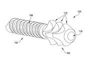
- FIG. 1is an isometric view of an improved hammer toe implant according to some embodiments
- FIG. 2is a top side view of the hammer toe implant illustrated in FIG. 1 ;
- FIG. 3is a top side view of the blade portion of the hammer toe implant illustrated in FIG. 6 ;
- FIG. 4is a sectional view of the hammer toe implant taken along line 3 - 3 in FIG. 2 ;
- FIG. 5is an end on view of the hammer toe implant taken along line 4 - 4 in FIG. 2 ;
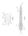
- FIG. 6is an isometric view of an improved, cannulated hammer toe implant according to some embodiments
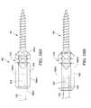
- FIG. 7is a side view of one example of a driving adapter for use with the hammer toe implants illustrated in FIGS. 1 and 6 ;
- FIG. 8is an end view of the driving adapter illustrated in FIG. 7 ;
- FIG. 9is a side view of another example of a driving adapter for use with the hammer toe implants illustrated in FIGS. 1 and 6 ;
- FIG. 10is an end view of the driving adapter illustrated in FIG. 9 ;
- FIG. 11Ais an assembly view of a hammer toe implant engaged by a driving adapter
- FIG. 11Bis an assembly view of a cannulated hammer toe implant engaged by a cannulated driving adapter
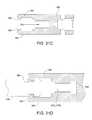
- FIG. 12Aillustrates the middle and proximal phalanxes of a foot being resected
- FIG. 12Billustrates the middle and proximal phalanxes of a foot being resected
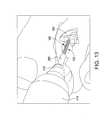
- FIG. 13illustrates a hammer toe implant being driven into a proximal phalanx
- FIG. 14illustrates a middle phalanx being drilled or broached
- FIG. 15illustrates a blade of a hammer toe implant extending from the proximal phalanx with the middle phalanx having been drilled or broached;
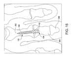
- FIG. 16illustrates a hammer toe implant installed in the middle and proximal phalanxes
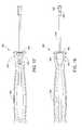
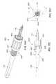
- FIG. 17illustrates another example of a driving assembly for installing an implant
- FIG. 18illustrates a side view of the driving assembly illustrated in FIG. 17 ;
- FIG. 19is an isometric view of an adapter of the driving assembly illustrated in FIG. 17 ;
- FIG. 20is an end view of the adapter illustrated in FIG. 19 ;
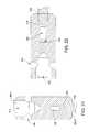
- FIG. 21is a cross-sectional view of the adapter taken along line 21 - 21 in FIG. 20 ;
- FIG. 22is a cross-sectional view of the adapter taken along line 22 - 22 in FIG. 20 ;
- FIG. 23is a plan view of the driving rod of the driving assembly illustrated in FIG. 17 ;
- FIG. 24is a cross-sectional view of the driving rod taken along line 24 - 24 in FIG. 23 ;
- FIG. 25is a cross-sectional view of the fin of the driving rod taken along line 25 - 25 in FIG. 23 ;
- FIG. 26is a plan view of driving assembly illustrated in FIG. 17 without the o-ring;
- FIG. 27is a cross-sectional view of the handle taken along line 27 - 27 in FIG. 26 ;
- FIG. 28Aillustrates an implant coupled to the adapter of the driving assembly illustrated in FIG. 17 ;
- FIG. 28Billustrates an implant coupled to the adapter of the driving assembly illustrated in FIG. 17 ;
- FIG. 29illustrates a hammer toe implant being driven into a proximal phalanx
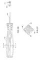
- FIG. 30illustrates an implant kit comprising a hammer toe implant preloaded in the adapter shown in FIGS. 19-22 ;
- FIG. 31Ais an isometric view of an implant kit according to some embodiments whose adapter has an implant receiving end configured to couple to an implant by an O-ring according to the adapter of FIGS. 19, 28A and 28B and having a driver shaft coupling end configured for coupling to the driver shaft by mating male and female threads;
- FIG. 31Bis an isometric view of an implant kit according to some embodiments whose adapter has an implant receiving end configured to couple to an implant by an O-ring according to the adapter of FIGS. 19, 28A and 28B and having a driver shaft coupling end configured for coupling to the driver shaft by a pair of opposing tabs;
- FIG. 31Cis a cross-sectional view of an adapter having a driver shaft coupling end illustrated in FIG. 31B and an implant receiving end according to some embodiments;
- FIG. 31Dis a cross-sectional view of an adapter having a driver shaft coupling end illustrated in FIG. 31A according to some embodiments;
- FIG. 32Ais an isometric view of an implant kit according to some embodiments whose adapter has an implant receiving end configured to couple to an implant by an O-ring according to the adapter of FIGS. 19, 28A and 28B and having a driver shaft coupling end configured for coupling to the driver shaft by an O-ring;
- FIG. 32Bis a side view of an adapter has an implant receiving end configured to couple to an implant by an O-ring according to the adapter of FIGS. 19, 28A and 28B and having a driver shaft coupling end configured for coupling to the driver shaft by an O-ring according to some embodiments;
- FIG. 32Cis a cross-sectional view of an implant kit whose adapter has a driver shaft coupling end for coupling to the driver shaft by an O-ring according to some embodiments;
- FIG. 33Ais a side view of an implant kit according to some embodiments whose adapter has an implant receiving end configured to couple to an implant by an O-ring according to the adapter of FIGS. 19, 28A and 28B and having a driver shaft coupling end configured for coupling to the driver shaft by an off-set clip;
- FIG. 33Bis an end perspective view of an adapter having a driver shaft coupling end configured for coupling to the driver shaft by an off-set clip according to some embodiments;
- FIG. 33Cis a cross-sectional view of an adapter having a driver shaft coupling end configured for coupling to the driver shaft by an off-set clip according to some embodiments;
- FIG. 34Ais an end perspective view of an adapter having a driver shaft coupling end configured for coupling to the driver shaft by a C-clip according to some embodiments;
- FIG. 34Bis an end view of an adapter having a driver shaft coupling end configured for coupling to the driver shaft by a C-clip according to some embodiments;
- FIG. 34Cis an end view of an adapter having a driver shaft coupling end configured for coupling to the driver shaft by a C-clip according to some embodiments;
- FIG. 34Dis cross-sectional view of an implant kit according to some embodiments having a driver shaft coupling end configured for coupling to the driver shaft by a C-clip;
- FIG. 34Eis a side view of a driver shaft configured for coupling to a driver shaft-coupling end of the adapter illustrated in FIG. 34D according to some embodiments;
- FIG. 35Ais an isometric view of some embodiments of an implant kit comprising an adapter that is configured for coupling to an hammer toe implant using a collet;
- FIG. 35Bis an isometric view of some embodiments of an implant kit comprising an adapter that is configured for coupling to an hammer toe implant using a collet and showing a hammer toe implant received in the adapter;
- FIG. 35Cis an isometric view of some embodiments of an implant kit comprising an adapter that is configured for coupling to an hammer toe implant using a collet;
- FIG. 35Dis a an end view of the implant kit illustrated in FIG. 35B ;
- FIG. 35Eis cross-sectional view of the implant kit taken along line 25 - 25 in FIG. 35D ;
- FIG. 35Fis cross-sectional view of the implant kit taken along line 25 - 25 in FIG. 35D .
- FIG. 1illustrates one example of an improved implant 100 for treating hammer toe.
- implant 100includes a threaded portion 102 and a blade portion 104 , which are connected together at an engagement portion 106 .
- implant 100has a substantially linear geometry.
- implant 100has an overall length of approximately 19 mm (approximately 0.75 inches) (e.g. 18.9-19.1 mm (0.74-0.76 inches)).
- blade portion 104can be disposed at angle with respect to a longitudinal axis defined by the threaded portion 102 .
- the anglecan be between zero and 45 degrees, and more particularly between approximately five and fifteen degrees, although one skilled in the art will understand that implant 100 can have other dimensions and be provided in different sizes.
- implant 100can be provided in lengths of 16 mm and 22 mm, to name a few potential lengths.
- threaded portion 102includes a plurality of threads 108 disposed along its entire length, which can be approximately 13 mm (approximately 0.5 inches) (e.g. 12.9-13.1 mm (0.49-0.51 inches)) although one skilled in the art will understand that threaded portion 102 can have other dimensions and be provided in different sizes.
- threaded portion 102can be provided in lengths of 10 mm and 15 mm, to name a few potential lengths.
- the tip 110 of threaded portion 102can be pointed to facilitate the advancement of threads 108 into bone.
- Threads 108can have a maximum outer diameter of approximately 2 mm (approximately 0.08 inches), although one skilled in the art will understand that thread portion 102 can have other dimensions and be configured to be received within a phalanx bone of a person.
- threadscan have an outer diameter of approximately 2.4 mm and 1.6 mm, to name a few potential possibilities.
- blade portion 104can have a substantially cylindrical cross-sectional geometry.
- blade portion 104can have other cross-sectional geometries.
- blade portion 104can have a taper defined by a plurality of blades 112 .
- the taper of blade portion 104can be at an angle relative to the longitudinal axis defined by the elongated central portion of implant 100 .
- the taperis at an angle ( ⁇ T ) between 1 and 10 degrees relative to the longitudinal axis defined by the elongated central portion of implant 100 .
- the tapercan be at an angle ( ⁇ T ) of approximately 5 degrees (e.g. 4.9-5.1 degrees) degrees relative to the longitudinal axis defined by the elongated central portion of implant 100 .
- blade portion 104includes a taper along its diameter defined by the plurality of blades 112 .
- the plurality of blades 112include a first blade 112 having a first diameter disposed proximate the engagement portion 106 and a second blade 112 having a second diameter smaller than the first diameter disposed proximate a terminating end 118 of the blade portion 104 .
- the first diametercan be approximately 5 mm (approximately 0.20 inches) (e.g. 4.9-5.1 mm) (0.19-0.21 inches) and the second diameter can be approximately 4.5 mm (approximately 0.18 inches) (e.g. 4.4-4.6 mm) although one skilled in the art will understand that the plurality of blades 112 can have other diameters and other dimensions.
- the first diametercan be provided as in lengths of 4 mm and 6 mm, to name a few potential diameters. The inventors have found that the tapered blade portion 104 permits each successive blade 112 of blade portion 104 to achieve interference with bone during insertion which enhances fixation of the blade portion 104 compared to a non-tapered blade portion 104 .
- the blades 112 of blade portion 104include a valley 126 between blades 112 and the teeth portions 114 of each blade 112 .
- valley 126 of teeth portions 114 of each blade 112is substantially the same.
- the valleys 126 of teeth portions 114vary as the respective diameters of the successive blades are tapered.
- the terminating end 118 of blade portion 104is a point, although one skilled in the art will understand that blade portion 104 can have a terminating end of other dimensions, sizes and/or shapes.
- the terminating end 118 of blade portion 104is cannulated.
- the blade portion 104 and threaded portion 102 of implant 100are cannulated.
- implant 100FIGS. 3, 6, 11B
- implant 100includes a groove 109 sized and configured to receive a k-wire, pin, or other surgical device or instrument that extends along the length of implant 100 in a direction that is parallel to a longitudinal length defined by implant 100 .
- the taper of blade portion 104can be defined by the plurality of blades 112 having successively smaller diameters between a blade 112 disposed proximate engagement portion 106 and a blade 112 disposed proximate terminating end 118 of the blade portion 104 .
- each blade 112 of the plurality of blades 112 of blade portion 104include a plurality of grooved portions 116 and a plurality of teeth portions 114 to form a substantially cruciform cross-sectional geometry ( FIG. 5 ).
- each blade 112 of blade portion 104 having a substantially cylindrical cross-sectionincludes a plurality of substantially rounded grooved portions 116 formed along an axis parallel to a longitudinal axis of blade portion 104 and a plurality of teeth portions 114 . As shown in FIGS.
- blade portion 104can have a substantially cylindrical cross-sectional geometry including a plurality of blades 112 having respective substantially cruciform cross-sectional geometries defined by a grooved portion 116 being disposed in each quadrant ( 112 a - d ) of each blade 112 .
- each blade 112 of blade portion 104includes a pair of opposing grooved portions 116 (e.g. in quadrants 112 b and 112 d and in quadrants 112 a and 112 c respectively) to form a substantially cruciform cross-sectional geometry.
- the grooved portions 116 of each pair of opposing grooved portions 116e.g.
- each blade 112in quadrants 112 a and 112 c and 112 b and 112 d respectively) are substantially symmetrical.
- the grooved portions 116 disposed in each quadrant ( 112 a - d ) of each blade 112are substantially symmetrical and the teeth portions 114 of each blade 112 are substantially symmetrical.
- each blade 112 of blade portion 104includes no flat surfaces.
- a centerline of grooved portion 116 of each blade 112 of blade portion 104is dimensioned such that it is tangent to respective diameters measured at the intersections of grooved portion 116 and the respective teeth portions 114 .
- grooved portions 116are concave in shape and teeth portions 114 are convex in shape.
- the respective surfaces of each blade 112are rounded.
- teeth portions 114are serrated.
- engagement portion 106can include a pair of protrusions extending from opposite sides of implant 100 and having rounded outer edges. In some embodiments, for example as shown in FIG. 2 , the sides of the protrusions of engagement portion 106 can be substantially parallel with each other. In some embodiments, at least a portion of the implant 100 is cannulated ( FIGS. 3, 6 ). The inventors have found that a cannulated implant 100 design can permit surgeons to stabilize joints (e.g. a metatarsal phalangeal joint (MPJ)) during a surgical procedure.
- MPJmetatarsal phalangeal joint
- Implant 100is configured to be installed using a driving adapter 200 such as the one illustrated in FIGS. 7-10 .
- the driving adapter 200has an elongated body 202 having a proximal end 204 and a distal end 206 .
- Body 202 of driving adapter 200can have a circular cross-sectional geometry, although one skilled in the art will understand that body 202 can have other cross-sectional geometries including, but not limited to, triangular, rectangular, pentagonal, and hexagonal to name a few.
- Proximal end 204can be substantially solid and have a rounded tip 208 .
- proximal end 204 and distal end 206can be cannulated such as, for example, to receive a k-wire.
- Distal end 206can define a slot 210 sized and configured to receive blade portion 104 of implant 100 therein.
- slot 210can have a cylindrical cross-sectional geometry and have a depth that is sufficient to receive the entire blade portion 104 of implant 100 such that distal edges 212 of slot 210 contact the protrusions of engagement portion 106 .
- slot 210can have a cylindrical, cruciform cross-sectional geometry and have a depth that is sufficient to receive the entire blade portion 104 of implant 100 such that distal edges 212 of slot 210 contact the protrusions of engagement portion 106 .
- slot 210can have other cross-sectional geometries and dimensions. Slot 210 can extend through side walls 214 of body 202 as shown in FIGS. 7 and 8 , or side walls 214 can completely enclose slot 210 as shown in FIGS. 9 and 10 .
- slot 210can extend in a direction that is substantially parallel to an axis defined by body 202 of driving adapter 200 . If driving adapter 200 is to be used with an implant 100 having a blade portion 104 that extends at an angle with respect to an axis defined by elongated threaded portion 102 , then slot 210 can extend from distal edges 212 at an angle with respect to an axis defined by the length of body 202 such that elongated threaded portion 102 of implant 100 is linearly aligned with body 202 of driving adapter 200 as shown in FIGS. 11A and 11B .
- slot 210 of driving adapter 200can extend at a ten degree angle with respect to a longitudinal axis defined by body 202 such that threaded portion 102 of implant 100 and body 202 of driving adapter 200 are substantially linearly aligned.
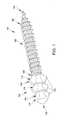
- a method of installing implant 100 in the proximal interphalangeal joint (PIP) 300is described with reference to FIGS. 12A-16 .
- the technique for installing the implant 100can be applied to other joints such as, for example, the distal interphelangeal (DIP) joint between middle phalanx 304 and distal phalanx 306 .
- DIPdistal interphelangeal
- FIGS. 12A and 12Ban incision is made to open the PIP joint 300 and a cutting tool 400 having a blade 402 can be used to resect adjacent faces of proximal phalanx 302 and middle phalanx 304 .
- the resected surfaces of proximal phalanx 302 and middle phalanx 304can be debrided as understood by one skilled in the art.
- Blade portion 104 of implant 100can be disposed within slot 210 of driving adapter 200 as shown in FIGS. 11A and 11B .
- the body 202 of driving adapter 200can be cannulated.
- a k-wire, pin or other suitable surgical devicecan be inserted into the middle phalanx 304 and driven through distal phalanx and out of the end of the toe (not shown).
- a k-wirecan be inserted such that a trailing end is disposed within middle phalanx 304 or otherwise positioned with respect to the joint such that cannulated implant 100 can be driven into proximal phalanx 302 .
- the body 202 of driving adapter 200can be secured in a chuck 412 of a drill 410 or other driving instrument as shown in FIG. 13 .
- Drill 410 or other driving instrumentis used to drive the threaded portion 102 of implant 100 into the resected surface of proximal phalanx 302 .
- driving adapter 200can be disengaged from blade portion 104 of implant 100 .
- Middle phalanx 304can be predrilled or broached using drill 410 to create a hole 308 as shown in FIGS. 14 and 15 .
- the predrilled or broached middle phalanx 304is then repositioned such that the predrilled hole or broach 308 aligns with the blade portion 104 of implant 100 .
- a dimension (e.g. diameter or width) of the predrilled hole or broach 308is less than a dimension of blade portion 104 to permit a first blade 112 to achieve interference with the bone and enhance fixation of blade 104 .
- “valley-to-valley” dimension of blade portion 104e.g. the diametrical dimension of blade portion 104 between blades 112 ).
- a k-wire or other suitable surgical deviceis disposed within middle phalanx 304 can be aligned with groove 109 of cannulated implant 100 ( FIGS. 3, 6, 11B ) disposed within proximal phalanx 302 .
- the middle phalanx 304can be then pressed into engagement with the blade portion 104 as shown in FIG. 16 .
- Serrated teeth portions or edges 114 of blade portion 104help to maintain the engagement between middle phalanx 304 and blade portion 104 of implant 100 .
- a k-wire or other suitable surgical devicecan be advanced into the joint, into and through middle phalanx 302 , into the respective metatarsal and through cannulated implant 100 .
- the k-wire or other suitable surgical devicecan remain within the patient for a period of time, e.g. minutes, hours, days or months, and can then be removed to leave behind cannulated implant 100 .
- FIGS. 17-27illustrate some embodiments of a driver assembly 500 for installing an implant into bone.
- driver assembly 500includes an adapter 502 coupled to a driving rod 516 onto which a handle 534 is over-molded or otherwise coupled.
- Adapter 502includes a body 504 with a substantially rectangular side profile comprising side walls 506 - 1 , 506 - 2 , 506 - 3 , and 506 - 4 (collectively referred to as “side walls 506 ”) and a pair of end walls 508 - 1 , 508 - 2 (collectively referred to as “end walls 508 ”) having a substantially square geometry as best seen in FIGS. 19-22 .
- Body 504defines a recess 510 along the length of side walls 506 .
- Recess 510is dimensioned such that an o-ring 544 ( FIGS. 17 and 18 ) can be received therein. Additionally, recess 510 is located along side walls 506 at a distance from end walls 508 such that recess 510 is aligned with a valley 126 of teeth portions 114 along the circumference of blade portion 104 .
- End wall 508 - 1defines an aperture 512 ( FIG. 20 ) having a geometry that complements the cross-sectional geometry of blade portion 104 of implant 100 .
- aperture 512can extend approximately parallel to the lengthwise direction of side walls 506 ( FIGS. 21-22 ). If the blade portion 104 of implant 100 is angled (not shown), then aperture 512 can extend from wall 508 - 1 at an angle relative to the plane defined by side wall 506 - 2 or 506 - 4 as will be understood by one skilled in the art.
- aperture 512has a depth that is greater than or equal to a length of blade portion 104 such that blade portion 104 can be received within body 504 and engagement portion 106 abuts end wall 508 - 1 .
- end wall 508 - 2defines an aperture that is sized and configured to receive an end of elongated driving rod 516 therein.
- driving rod 516includes a fin 518 disposed at a first end 520 .
- Fin 518 disposed at end 520 of driving rod 516has a rectangular shape and is sized and configured to be received within aperture 512 of adapter 502 .
- Fin 518defines a slot 522 , which is sized and configured to receive a pin (not shown) for cross-pinning driving rod 516 to adapter 502 .
- end 520can have other cross-sectional geometries including, but not limited to, triangular, square, and pentagonal, to name a few possibilities, that are configured to be received within aperture 514 .
- Adapter 502can be over-molded onto the end of driving rod 516 . However, one skilled in the art will understand that adapter 502 can be cross-pinned or otherwise coupled to driving rod 516 .
- the opposite end 524 of driving rod 516defines a pair of flats 526 , 528 , which are disposed on opposite sides of driving rod 516 .
- flat 526extends from tip 530 and is linearly spaced from flat 528 , which is disposed at a greater distance from tip 530 than flat 526 .
- flats 526 , 528can be disposed at other positions along driving rod 516 .
- Flats 526 , 528are configured to provide a contact surface for coupling to handle 532 ( FIG. 26 ), which can be over-molded onto driving rod 516 , such that rotation of handle 532 is translated to driving rod 516 .
- handle 532has an elongated body 534 that includes a plurality of ribs 536 that extend in a longitudinal direction along body 534 to provide a gripping surface for a user.
- a smooth surface 538interrupts circumferential ridges 540 , which are disposed adjacent to proximal end 542 also for providing a gripping surface for a user.
- Driver assembly 500can be provided in a kit with a first adapter 502 for use with a straight implant 100 and a second adapter for use with an angled implant 100 .
- a plurality of implants 100 of different sizescan also be provided in the kit.
- the kitcan be used in an operation similar to the operation described above with respect to FIGS. 12A-16 .
- Blade portion 104 of implant 100is disposed within aperture 512 of adapter 502 as shown in FIGS. 28A and 28B .
- an o-ring 544( FIGS. 17 and 18 ) is placed in recess 510 defined by adapter 502 and within a valley 126 of serrated edges 112 along the top and bottom sides 114 , 116 of blade portion 104 .
- O-ring 544secures implant 100 to adapter 502 such that implant does not move axially out of aperture 512 .
- Implant 100is secured to adapter 502 , the surgeon uses handle 534 to manually drive threaded portion 102 of implant 100 into the resected surface of proximal phalanx 302 as illustrated in FIG. 29 .
- Implant 100is driven into proximal phalanx 302 until engagement portion 106 abuts proximal phalanx 302 .
- Implant 100is decoupled from adapter 502 by axially pulling handle 534 away from implant 100 with sufficient force to flex o-ring 544 and separate adapter 502 from implant 100 .
- Middle phalanx 304can be predrilled or broached using drill 410 to create a hole 308 as shown in FIGS. 14 and 15 .
- the predrilled or broached middle phalanx 304is then repositioned such that the predrilled hole or broach 308 aligns with the blade portion 104 of implant 100 .
- the middle phalanx 304is then pressed into engagement with the blade portion 104 as shown in FIG. 16 .
- Serrated teeth portions 114 of blade portion 104help to maintain the engagement between middle phalanx 304 and blade portion 104 of implant 100 .
- the implant described abovecan advantageously be installed through a small incision as described above. Additionally, the improved implant is completely disposed within a toe of a patient, which prevents the implant from being caught on bed sheets or other objects like the conventional pins.
- the implantcan be preloaded into an adapter and provided as an implant kit.
- an implant kitVarious embodiments of such an implant kit will be described below.
- FIG. 30is a view of the implant kit 1000 in which the implant 100 , 100 A is preloaded into the adapter 502 .
- FIG. 30is viewed from within the plane of FIGS. 28A and 28B so that the view shows the full circumference of the blade portion 104 , 104 A.
- an elastic O-ring 544also shown in FIGS. 17 and 18 ) placed in the groove 510 retains the implant 100 , 100 A in the adapter 502 , 502 A by preventing the implant from sliding out of the adapter.
- the cross-sections of the O-ringis shown in FIG. 30 .
- the groove 510is cut into the adapter with a sufficient depth so that when the O-ring 544 is placed therein the O-ring is positioned within the valley 126 between two adjacent teeth portions 114 about the circumference of the blade portion 104 , 104 A, as shown in FIG. 30 . Because the O-ring 544 is elastic, one can push the blade portion 104 , 104 A of the implant into the adapter with sufficient force for one or more of the teeth portions 114 to push past the O-ring 544 when assembling the implant kit 1000 . Once the implant kit 1000 is assembled, however, the O-ring 544 secures and retains the implant 100 , 100 A in the adapter 502 until one intentionally pulls off the adapter 502 after the implant is driven into a bone.
- the surgeonwould attach the implant kit 1000 to the driver tool 500 to manually drive the threaded portion 102 of the implant 100 , 100 A into the resected surface of proximal phalanx 302 as illustrated in FIG. 29 .
- the implant 100 , 100 Ais driven into the proximal phalanx 302 until engagement portion 106 abuts the proximal phalanx 302 .
- the implant 100 , 100 Ais then decoupled from the adapter 502 by axially pulling the adapter 502 away from the implant 100 , 100 A with sufficient force to push the O-ring 544 outward and separate the adapter 502 from the implant 100 , 100 A. Referring to FIGS.
- FIGS. 31A-31Dare various views of some embodiments of an adapter such as the adapter 502 of FIGS. 28A, 28B, and 30 having a driver shaft coupling end configured for coupling to the adapter-engaging end 517 a , 517 b of the driver shaft.
- the driver shaft coupling end of the adapter 502is provided with the longitudinally extending bore 514 , configured for receiving the adapter-engaging end 517 a , 517 b , and a pair of opposing tabs 541 , 542 extending longitudinally in the direction away from the implant engaging end.
- FIG. 31Ashows a driver shaft 516 whose adapter-engaging end 517 a is configured with screw threads.
- the driver-engaging end of the adapter 502is configured to threadably couple to the adapter-engaging end 517 a of the driver shaft 502 and the tabs 541 , 542 provide additional locking mechanism.
- FIG. 31Bshows a driver shaft 516 whose adapter-engaging end 517 b is configured with a magnetic tip.
- the driver-engaging end of the adapter 502is configured to magnetically couple to the adapter-engaging end 517 b and the tabs 541 , 542 provide additional locking mechanism.
- the adapter 502would then be provided with a magnet or a piece of magnetic material 503 for magnetically coupling to the adapter-engaging end 517 b.
- FIGS. 31C and 31Dare cross-sectional views of the adapter 502 showing the driver-engaging end.
- FIG. 31Cshows the profile of the tabs 541 and 542 and the bore 514 for receiving the adapter-engaging end 517 of the driver shaft.
- the bore 514is tapped with screw thread for threadably engaging the threaded adapter-engaging end 517 a .
- the bore 514is provided with a magnet 530 for engaging the magnetized tip of the adapter-engaging end 517 b.
- the tabs 541 , 542 and the adapter-engaging end 517 a , 517 bare configured for further mechanical coupling.
- the tabs 541 , 542are provided with bumps 550 and the adapter-engaging end 517 a , 517 b of the driver shaft is provided with corresponding cutouts 560 for mating with the bumps 550 .
- FIGS. 32A-32CShown in FIGS. 32A-32C are various views of an implant kit 1040 comprising an adapter 1502 and an implant 100 according to some embodiments.
- the implant 100is removably coupled to the adapter 1502 at the adapter's implant-receiving end 1503 by a first O-ring 544 in the same manner as with the adapter 502 shown in FIGS. 19, 28A, 28B and 30 .
- the adapter 1502has a circumferential groove 1510 , in which the first O-ring 544 is provided, in the outer surface of the adapter in proximity to the implant-receiving end 1503 .
- the adapter 1502comprises a slot provided in the implant-receiving end 1503 that receives the blade portion 104 of the implant 100 .
- the adapter 1502also has a driver shaft coupling end 1504 configured for removably coupling to the driver shaft 516 by a second O-ring 546 .
- the driver shaft coupling end 1504is provided with a longitudinally extending bore 1514 for receiving the adapter-engaging end 1517 of the driver shaft 516 .
- the driver shaft coupling end 1504is also provided with a second circumferential groove 1512 in which the second O-ring 546 is disposed.
- the adapter-engaging end 1517has a cross-section that is larger than the inner diameter of the second O-ring 546 but has a turned down section 1518 that has a reduced cross-section for accommodating the second O-ring 546 when the adapter-engaging end 1517 is inserted into the bore 1514 as shown in FIG. 32C .
- the turned down section 1518 and the second circumferential groove 1512align so that the second O-ring 546 rests in the turned down section 1518 .
- the second O-ring 546thus provides an interference with the adapter-engaging end 1517 to prevent the adapter 1502 and the driver shaft 516 from decoupling without exerting some force.
- FIGS. 33A-33Care various views of an adapter 2502 that can be used in an implant kit 1050 according to some embodiments of the present disclosure.
- the adapter 2502has an implant receiving end 2503 configured to couple to an implant 100 by an O-ring 544 according to the adapter of FIGS. 19, 28A and 28B and a driver shaft coupling end 2504 configured for coupling to the driver shaft 516 by an off-set clip 2515 .
- the driver shaft coupling end 2504has a longitudinally extending bore 2514 for receiving an adapter-engaging end 2517 of the driver shaft 516 .
- the off-set clip 2515is cantilevered to the adapter having a cantilever portion 2515 a connected to the adapter body and a locking portion 2515 b extending orthogonal to the cantilever portion 2515 a .
- the locking portion 2515 bis provided with a through hole 2516 for the adapter-engaging end 2517 of the driver shaft 516 .
- the through hole 2516 and the bore 2514are off-set to enable the locking function.
- the adapter-engaging end 2517is provided with a groove or a cutout 2518 on one side for removably engaging the off-set clip 2515 .
- the userpushes the off-set clip 2515 in the direction shown by the arrow P in FIG. 33C , which is a longitudinal cross-sectional view of the adapter 2502 . That will deflect the cantilever portion 2515 a in the direction P and bring the through hole 2516 in linear alignment with the bore 2514 so that the adapter-engaging end 2517 can be inserted through the through hole 2516 and the bore 2514 .
- the off-set clip 2515is released to its normal off-set position as shown in FIG. 40C .
- the off-set position of the locking portion 2515 bkeeps the locking portion 2515 b seated within the cutout 2518 keeping the driver shaft 516 coupled to the adapter 2502 .
- the off-set clipcan be configured so that in the configuration shown in FIG. 33C , the locking portion 2515 b maintains a force against the cutout 2518 in the direction opposite the arrow P.
- the off-set clip 2515is pushed in the direction of the arrow P shown in FIG. 33C bringing the through hole 2516 and the bore 2514 into longitudinal alignment and thus removing the interference between the locking portion 2515 b and the cutout 2518 .
- the adapter-engaging end 2517may simply be straight without the cutout 2518 structure. In that embodiment, the urging of the locking portion 2515 b against the straight adapter-engaging end 2517 in the direction opposite the arrow P will provide sufficient frictional interference to keep the driver shaft 516 and the adapter 2502 coupled.
- FIGS. 34A-34Eare various views of the driver shaft coupling end 3504 of an adapter 3502 that is configured for removably coupling to the implant 100 to form an implant kit according to some embodiments.
- the implant-receiving end of the adapter 3502is configured to couple to the implant by an O-ring 544 according to the adapter of FIGS. 19, 28A and 28B .
- the driver shaft coupling end 3504is configured to removably couple to the adapter-engaging end 3517 of the driver shaft 516 by a C-clip 3550 .
- the C-clip 3550is generally shaped like a letter C and has two prongs 3550 a and 3550 b joined at one end and open at the opposite end.
- the driver shaft coupling end 3504 of the adapter 3502is provided with a bore 3514 for receiving the adapter-engaging end 3517 .
- the driver shaft coupling end 3504is further configured with a pair of slots 3512 for receiving the C-clip 3550 and oriented orthogonal to the longitudinal axis of the adapter 3502 .
- FIG. 34Bis an end view of the adapter assembly viewed from the driver shaft coupling end 3504 showing the C-clip 3550 clipped on to the adapter 3502 by sliding the two prongs 3550 a , 3550 b into the pair of slots 3512 .
- the pair of slots 3512are cut into the adapter 3502 sufficiently deep to overlap with the bore 3514 so that when the C-clip 3550 is clipped on to the adapter 3502 , interference tabs 3551 on each of the two prongs 3550 a , 3550 b protrude into the bore 3514 as shown in FIG. 34B .
- the interference tabs 3551reside in the corresponding slots 3518 provided in the adapter-engaging end 3517 and prevent the adapter 3502 and the driver shaft 516 from decoupling.
- the interference tabs 3551are oriented substantially parallel to one another. In one preferred embodiment, the interference tabs 3551 can be oriented in a slant so that the interference tabs 3551 are tapered towards the open end of the C-clip 3550 . The tapered interference tabs 3551 makes is easier to insert the C-clip 3550 over the adapter-engaging end 3517 .
- FIGS. 35A-35Fare various views of some embodiments of an implant kit 1030 comprising an adapter 2600 configured for coupling to a hammer toe implant 100 using a thread-biased collet 2650 .
- the adapter 2600comprises a sleeve 2602 and the collet 2650 .
- the sleeve 2602has openings at each end and a bore 2615 longitudinally extending between the two openings.
- sleeve 2602can include a plurality of ribs that extend in a longitudinal direction along sleeve 2602 to provide a gripping surface for a user.
- the collet 2650is received in the bore 2615 .
- the sleeve 2602has a first end 2605 that forms one of the openings.
- the collet 2650is generally cylindrical in shape and comprises an implant receiving portion 2657 and a threaded portion 2660 .
- the threaded portion 2660is provided with screw threads 2663 .
- the implant receiving portion 2657has an implant-receiving opening 2612 for receiving the blade portion 104 of the implant 100 .
- the implant-receiving opening 2612is defined by collet segments 2651 which are defined by slots 2652 extending from the implant-receiving end towards the threaded portion 2660 .
- This example of a collethas two collet segments 2651 .
- the implant receiving portion 2657is flared in its outer circumference so that the diameter of the receiving portion 2657 increases towards the implant-receiving end of the collet.
- FIG. 35Bshows the collet 2650 with the implant 100 received in the slots 2652 .
- FIG. 35Cshows the collet with an indicated direction of rotation L to drive the sleeve 2602 onto the threaded portion 2660 to retain the implant 100 within implant receiving portion 2657 .
- the refraction and extension of the collet 2650is enabled by turning the sleeve 2602 about a longitudinal axis relative to the collet 2650 thus engaging the screw threads 2607 and 2663 .
- sleeve 2602is driven by hand in direction of rotation L to retain implant 100 within implant receiving portion 2657 pre-implantation and in an opposite direction of L to release implant 100 post-implantation.
- FIG. 35Dis an end view of the adapter 2600 illustrated in FIGS. 35A-35C and shows the implant 100 received in the implant receiving end 2657 and slots 2652 .
- the implant-receiving opening 2612 of implant receiving portion 2657has a geometry that complements the cross-sectional geometry of blade portion 104 of implant 100 and is defined by collet segments 2651 which are defined by slots 2652 .
- implant 100has a cylindrical, cruciform straight blade portion 104 as illustrated in FIG. 2 and FIG. 35A
- implant-receiving opening 2612can extend approximately parallel to the lengthwise direction of collet 2650 .
- implant-receiving opening 2612can extend from end 2603 at an angle relative to the plane defined by collet 2650 as will be understood by one skilled in the art.
- collet segments 2651 of implant receiving end 2657include radii features to complement radii features of the cylindrical, cruciform blade portion 104 .
- the bore 2615has a screw threaded portion 2607 and a main portion 2605 .
- the threaded portion 2607is configured to threadably engage the threads 2663 of the collet 2650 .
- the main portion 2605has a sufficiently large diameter to accommodate a substantial portion of the implant receiving portion 2657 of the collet 2650 without imposing any mechanical interference.
- the main portion 2605terminates at the first end 2603 where the opening formed therein has a diameter smaller than the maximum diameter of the flared implant receiving portion 2657 . This configuration allows the collet segments 2651 to be constricted by the first end 2603 when the collet 2650 is retracted into the sleeve 2602 in the direction R shown in FIG.
- the implant 100can be released from the adapter 2600 by extending the collet 2650 outward from the sleeve 2602 in the direction E shown in FIG. 35F .
- sleeve 2602includes an internal taper to interface with an external taper of the implant receiving portion 2657 of collet 2650 .
- Some embodimentsprovide an implant including an elongated threaded portion and a blade portion extending from the elongated threaded portion.
- the blade portionhas a substantially cylindrical cross-sectional geometry and a taper defined by a plurality of blades.
- Some embodimentsprovide an implant including an elongated threaded portion and a blade portion extending from the elongated threaded portion.
- the blade portionincludes a plurality of blades having respective substantially cruciform cross-sectional geometries defined by a grooved portion being disposed in each quadrant of each blade.
- Some embodimentsprovide a method including forming an incision to gain access to a joint between first and second bones, flexing the first and second bones such that the bones are disposed at an angle from one another, and advancing a threaded portion of an implant into the first bone.
- the implantincludes a blade portion extending from an elongated threaded portion.
- the blade portionhas a substantially cylindrical cross-sectional geometry and a taper defined by a plurality of blades.
- the methodalso includes repositioning the second bone such that a middle of the second bone is approximately aligned with the blade portion of the implant and forcing the second bone into engagement with the blade portion of the implant.
Landscapes
- Health & Medical Sciences (AREA)
- Orthopedic Medicine & Surgery (AREA)
- Life Sciences & Earth Sciences (AREA)
- Surgery (AREA)
- Animal Behavior & Ethology (AREA)
- Veterinary Medicine (AREA)
- Public Health (AREA)
- Engineering & Computer Science (AREA)
- Biomedical Technology (AREA)
- Heart & Thoracic Surgery (AREA)
- General Health & Medical Sciences (AREA)
- Molecular Biology (AREA)
- Medical Informatics (AREA)
- Nuclear Medicine, Radiotherapy & Molecular Imaging (AREA)
- Neurology (AREA)
- Prostheses (AREA)
- Cardiology (AREA)
- Oral & Maxillofacial Surgery (AREA)
- Transplantation (AREA)
- Vascular Medicine (AREA)
Abstract
Description
Claims (15)
Priority Applications (10)
| Application Number | Priority Date | Filing Date | Title |
|---|---|---|---|
| US14/052,046US9724140B2 (en) | 2010-06-02 | 2013-10-11 | Tapered, cylindrical cruciform hammer toe implant and method |
| AU2014311181AAU2014311181B2 (en) | 2013-10-11 | 2014-10-01 | Tapered, cylindrical cruciform hammer toe implant and method |
| BR112016000290ABR112016000290A8 (en) | 2013-10-11 | 2014-10-01 | conical, cylindrical and cruciform hammer toe implant kit |
| EP14841325.5AEP2882377B1 (en) | 2013-10-11 | 2014-10-01 | Tapered, cylindrical cruciform hammer toe implant kit |
| EP15169014.6AEP2929850B1 (en) | 2013-10-11 | 2014-10-01 | Cylindrical cruciform hammer toe implant |
| CA2889318ACA2889318C (en) | 2013-10-11 | 2014-10-01 | Tapered, cylindrical cruciform hammer toe implant and method |
| JP2016533517AJP6189542B2 (en) | 2013-10-11 | 2014-10-01 | Tapered cylindrical cruciform saddle-shaped toe implant |
| CN201480041060.6ACN105431110A (en) | 2013-10-11 | 2014-10-01 | Tapered, cylindrical cruciform hammer toe implant and method |
| PCT/US2014/058600WO2015054001A1 (en) | 2013-10-11 | 2014-10-01 | Tapered, cylindrical cruciform hammer toe implant and method |
| AU2017200430AAU2017200430B2 (en) | 2013-10-11 | 2017-01-20 | Tapered, cylindrical cruciform hammer toe implant and method |
Applications Claiming Priority (5)
| Application Number | Priority Date | Filing Date | Title |
|---|---|---|---|
| US35066510P | 2010-06-02 | 2010-06-02 | |
| US13/086,136US9072564B2 (en) | 2010-06-02 | 2011-04-13 | Hammer toe implant and method |
| US13/660,522US9044287B2 (en) | 2010-06-02 | 2012-10-25 | Hammer toe implant method |
| US13/804,228US9498273B2 (en) | 2010-06-02 | 2013-03-14 | Orthopedic implant kit |
| US14/052,046US9724140B2 (en) | 2010-06-02 | 2013-10-11 | Tapered, cylindrical cruciform hammer toe implant and method |
Related Parent Applications (1)
| Application Number | Title | Priority Date | Filing Date |
|---|---|---|---|
| US13/660,522Continuation-In-PartUS9044287B2 (en) | 2010-06-02 | 2012-10-25 | Hammer toe implant method |
Publications (2)
| Publication Number | Publication Date |
|---|---|
| US20140142715A1 US20140142715A1 (en) | 2014-05-22 |
| US9724140B2true US9724140B2 (en) | 2017-08-08 |
Family
ID=50728687
Family Applications (1)
| Application Number | Title | Priority Date | Filing Date |
|---|---|---|---|
| US14/052,046Active2031-05-19US9724140B2 (en) | 2010-06-02 | 2013-10-11 | Tapered, cylindrical cruciform hammer toe implant and method |
Country Status (1)
| Country | Link |
|---|---|
| US (1) | US9724140B2 (en) |
Cited By (12)
| Publication number | Priority date | Publication date | Assignee | Title |
|---|---|---|---|---|
| US20170100172A1 (en)* | 2011-12-12 | 2017-04-13 | Wright Medical Technology, Inc. | Fusion implant |
| USD816469S1 (en)* | 2017-01-11 | 2018-05-01 | Marshall Lee Toomey | Deep groove screw |
| US10702318B2 (en) | 2015-03-03 | 2020-07-07 | Howmedica Osteonics Corp. | Orthopedic implant and methods of implanting and removing same |
| US10772733B2 (en)* | 2018-03-01 | 2020-09-15 | Paragon 28, Inc. | Implants and methods of use and assembly |
| US10912594B2 (en) | 2007-03-20 | 2021-02-09 | Stryker European Holdings I, Llc | Osteosynthesis device |
| US11045239B2 (en) | 2018-09-14 | 2021-06-29 | Voom Medical Devices, Inc. | Orthopedic bone screw |
| US11147681B2 (en) | 2017-09-05 | 2021-10-19 | ExsoMed Corporation | Small bone angled compression screw |
| US11191645B2 (en) | 2017-09-05 | 2021-12-07 | ExsoMed Corporation | Small bone tapered compression screw |
| US11246712B2 (en)* | 2018-03-01 | 2022-02-15 | Paragon 28, Inc. | Implants, systems, and methods of use and assembly |
| US11478285B2 (en) | 2005-04-14 | 2022-10-25 | Stryker European Operations Holdings Llc | Device for osteosyntheses or arthrodesis of two-bone parts, in particular of the hand and/or foot |
| US12310839B2 (en)* | 2017-06-12 | 2025-05-27 | Conmed Corporation | Expanding anchor |
| US12383319B2 (en) | 2008-09-09 | 2025-08-12 | Stryker European Operations Holdings Llc | Resorptive intramedullary implant between two bones or two bone fragments |
Families Citing this family (19)
| Publication number | Priority date | Publication date | Assignee | Title |
|---|---|---|---|---|
| US8608785B2 (en) | 2010-06-02 | 2013-12-17 | Wright Medical Technology, Inc. | Hammer toe implant with expansion portion for retrograde approach |
| US9498273B2 (en) | 2010-06-02 | 2016-11-22 | Wright Medical Technology, Inc. | Orthopedic implant kit |
| US9724138B2 (en) | 2011-09-22 | 2017-08-08 | Arthrex, Inc. | Intermedullary devices for generating and applying compression within a body |
| DE202013011213U1 (en)* | 2012-10-01 | 2014-04-16 | Nextremity Solutions, Inc. | Reversible bone coupling device |
| US8945232B2 (en) | 2012-12-31 | 2015-02-03 | Wright Medical Technology, Inc. | Ball and socket implants for correction of hammer toes and claw toes |
| US9724139B2 (en) | 2013-10-01 | 2017-08-08 | Wright Medical Technology, Inc. | Hammer toe implant and method |
| US9474561B2 (en)* | 2013-11-19 | 2016-10-25 | Wright Medical Technology, Inc. | Two-wire technique for installing hammertoe implant |
| WO2015090954A1 (en)* | 2013-12-17 | 2015-06-25 | Stichting Katholieke Universiteit | Intramedullary device for mid-shaft clavicle fractures |
| US9498266B2 (en) | 2014-02-12 | 2016-11-22 | Wright Medical Technology, Inc. | Intramedullary implant, system, and method for inserting an implant into a bone |
| US9545274B2 (en)* | 2014-02-12 | 2017-01-17 | Wright Medical Technology, Inc. | Intramedullary implant, system, and method for inserting an implant into a bone |
| USD749738S1 (en)* | 2014-08-15 | 2016-02-16 | Nextremity Solutions, Inc. | Toe implant |
| AU2014331633B2 (en) | 2014-09-18 | 2017-06-22 | Wright Medical Technology, Inc | Hammertoe implant and instrument |
| CN105960211B (en) | 2014-12-19 | 2019-01-11 | 瑞特医疗技术公司 | Intramedullary Anchors for Interphalangeal Arthrodesis |
| WO2017192632A1 (en)* | 2016-05-03 | 2017-11-09 | Additive Orthopaedics, LLC | Bone fixation device and method of use |
| EP3251621B1 (en) | 2016-06-03 | 2021-01-20 | Stryker European Holdings I, LLC | Intramedullary implant |
| US10531903B2 (en) | 2016-12-06 | 2020-01-14 | DePuy Synthes Products, Inc. | Orthopedic break-off screws, tools for inserting such screws, and related systems and methods |
| US10660676B2 (en) | 2017-02-20 | 2020-05-26 | Paragon 28, Inc. | Implants, devices, instruments, systems and methods of forming and implanting |
| KR101934391B1 (en)* | 2017-07-18 | 2019-01-02 | 주식회사 솔고 바이오메디칼 | Sleeve pin assembly for fixing bone pieces |
| WO2021097491A1 (en) | 2019-11-15 | 2021-05-20 | Paragon 28, Inc. | Instruments, systems, and methods of using |
Citations (499)
| Publication number | Priority date | Publication date | Assignee | Title |
|---|---|---|---|---|
| US321389A (en) | 1885-06-30 | Combined nail and screw | ||
| US346148A (en) | 1886-07-27 | Daniel p | ||
| US348589A (en) | 1886-09-07 | sloan | ||
| US373074A (en) | 1887-11-15 | Wood-screw | ||
| US430236A (en) | 1890-06-17 | Island | ||
| US561968A (en) | 1896-06-16 | Georges cotjlon | ||
| US736121A (en) | 1902-04-21 | 1903-08-11 | Abraham B Lipscomb | Boot-calk. |
| US821025A (en) | 1903-01-27 | 1906-05-22 | Joseph Bartlett Davies | Nail or screw for securing corrugated iron. |
| US882937A (en) | 1908-03-24 | North Bros M F G Co | Screw-eye driver. | |
| GB140983A (en) | 1919-10-27 | 1920-04-08 | Charles Louis Basham | Improvements in wood screws |
| FR736058A (en) | 1932-04-28 | 1932-11-18 | Improvements made to bolts to ensure the safety of assemblies | |
| US1966835A (en) | 1932-01-28 | 1934-07-17 | Dardelet Threadlock Corp | Fastening means |
| US2140749A (en) | 1936-08-05 | 1938-12-20 | Filshie Lead Head Nail Company | Capped nail |
| US2361107A (en) | 1944-03-08 | 1944-10-24 | Charles E Johnson | Self-locking valve tappet screw |
| US2451747A (en) | 1945-03-23 | 1948-10-19 | Ernest T Kindt | Doweled structure |
| US2490364A (en) | 1948-02-27 | 1949-12-06 | Herman H Livingston | Bone pin |
| US2600517A (en) | 1948-09-29 | 1952-06-17 | Herschel L Rushing | Tell-tale screw spike |
| FR1036978A (en) | 1951-05-11 | 1953-09-14 | Karcher Schraubenwerke G M B H | Bolt |
| US2697370A (en) | 1951-09-04 | 1954-12-21 | Linzy W Brooks | Ratchet type socket wrench |
| US2832245A (en) | 1956-02-15 | 1958-04-29 | Burrows Allen | Sponge-rubber liner for socket wrench |
| US2895368A (en) | 1955-01-21 | 1959-07-21 | Jr Paul R Trigg | Bolt having rolled grooves and recessed head to enhance uniform elongation |
| US3462765A (en) | 1967-01-06 | 1969-08-26 | Dow Corning | Surgically implantable prosthetic joint |
| US3466669A (en) | 1966-09-20 | 1969-09-16 | Univ Iowa | Intramedullary finger joint prosthesis |
| US3593342A (en) | 1969-01-27 | 1971-07-20 | Cutter Lab | Prosthetic joint |
| US3681786A (en) | 1970-07-13 | 1972-08-08 | Medical Eng Corp | Solid human prosthesis of varying consistency |
| US3739403A (en) | 1970-10-09 | 1973-06-19 | F Nicolle | Prosthetic joint having a tissue ingrowth preventive capsule |
| US3759257A (en) | 1971-03-13 | 1973-09-18 | Fischer Artur | Connector for fractured tubular bones |
| US3760802A (en) | 1971-02-26 | 1973-09-25 | Fischer Artur | Supporting device for fractured tubular bones |
| US3779239A (en) | 1971-03-13 | 1973-12-18 | Fischer Artur | Connector for fractured bones |
| US3824631A (en) | 1973-05-11 | 1974-07-23 | Sampson Corp | Bone joint fusion prosthesis |
| USD243716S (en) | 1975-07-24 | 1977-03-15 | Richards Manufacturing Company, Inc. | Great toe prosthesis |
| US4047524A (en) | 1975-04-28 | 1977-09-13 | Downs Surgical Limited | Surgical implant spinal staple |
| US4096896A (en) | 1977-04-29 | 1978-06-27 | Upson Tools, Inc. | Composite tool structure |
| JPS53128181A (en) | 1977-02-24 | 1978-11-08 | Herbert Timothy James | Screw for bonding bones |
| US4156296A (en) | 1977-04-08 | 1979-05-29 | Bio-Dynamics, Inc. | Great (large) toe prosthesis and method of implanting |
| US4170990A (en) | 1977-01-28 | 1979-10-16 | Fried. Krupp Gesellschaft Mit Beschrankter Haftung | Method for implanting and subsequently removing mechanical connecting elements from living tissue |
| US4198713A (en) | 1976-10-12 | 1980-04-22 | Swanson Alfred B | Protective member for implantable prosthesis and method of protecting the prosthesis |
| US4204284A (en) | 1977-11-16 | 1980-05-27 | Lord Corporation | Joint prosthesis with contoured pin |
| US4213208A (en) | 1977-12-05 | 1980-07-22 | Sheldon Marne | Metatarso-phalangeal joint implant |
| US4237875A (en) | 1979-02-23 | 1980-12-09 | Towmotor Corporation | Dynamic intramedullary compression nailing |
| US4262665A (en) | 1979-06-27 | 1981-04-21 | Roalstad W L | Intramedullary compression device |
| US4263903A (en) | 1979-01-08 | 1981-04-28 | Richards Manufacturing Co., Inc. | Medical staple means |
| US4275717A (en) | 1979-07-27 | 1981-06-30 | Zimmer Usa, Inc. | Intramedullary fixation device for fractured tubular bones |
| US4276660A (en) | 1979-05-25 | 1981-07-07 | Laure Prosthetics, Inc. | Carpometacarpal thumb joint |
| US4278091A (en) | 1980-02-01 | 1981-07-14 | Howmedica, Inc. | Soft tissue retainer for use with bone implants, especially bone staples |
| US4304011A (en) | 1980-08-25 | 1981-12-08 | Whelan Iii Edward J | Semi-constrained metacarpophalangeal prosthesis |
| US4321002A (en) | 1978-03-27 | 1982-03-23 | Minnesota Mining And Manufacturing Company | Medical stapling device |
| US4364382A (en) | 1979-08-23 | 1982-12-21 | Ulrich Mennen | Internal fixation device for bone fractures |
| US4367562A (en) | 1980-06-19 | 1983-01-11 | Georges Gauthier | Joint prosthesis |
| US4404874A (en) | 1980-05-02 | 1983-09-20 | Firma Hermann Werner Gmbh & Co. | Screwdriver with replaceable blade |
| GB2119655A (en) | 1982-05-06 | 1983-11-23 | Nat Res Dev | Endoprosthesis |
| US4434796A (en) | 1981-04-07 | 1984-03-06 | Vsesojuzny Nauchno-Issledovatelsky I Ispytatelny Institut Meditsinskoi Tekhniki | Surgical staple, a method of and forceps for its removal |
| US4454875A (en) | 1982-04-15 | 1984-06-19 | Techmedica, Inc. | Osteal medical staple |
| US4485816A (en) | 1981-06-25 | 1984-12-04 | Alchemia | Shape-memory surgical staple apparatus and method for use in surgical suturing |
| EP0127994A1 (en) | 1983-06-02 | 1984-12-12 | Pfizer Hospital Products Group, Inc. | Arched bridge staple |
| USD277509S (en) | 1982-07-01 | 1985-02-05 | Sutter Biomedical Inc. | Great toe metatarsal phalangeal implant |
| USD277784S (en) | 1982-06-25 | 1985-02-26 | Sutter Biomedical, Inc. | Lesser toe metatarsal phalangeal implant |
| SU1152582A1 (en) | 1982-09-24 | 1985-04-30 | Новокузнецкий институт усовершенствования врачей | Clip for osteosynthesis |
| US4516569A (en) | 1982-05-06 | 1985-05-14 | National Research Development Corporation | Intramedullary orthopaedic devices |
| JPS60145133A (en) | 1984-01-09 | 1985-07-31 | 工業技術院長 | Bone connection tool |
| US4590928A (en) | 1980-09-25 | 1986-05-27 | South African Invention Development Corporation | Surgical implant |
| USD284099S (en) | 1983-03-14 | 1986-06-03 | Sutter Bio-Medical, Inc. | Great toe metatarsal phalangeal implant |
| US4634382A (en) | 1984-06-07 | 1987-01-06 | Molten Corp. | Attachment for dental prosthesis |
| US4642122A (en) | 1986-04-02 | 1987-02-10 | Laure Prosthetics, Inc. | Toe implant |
| US4655661A (en) | 1983-12-23 | 1987-04-07 | Richter-System Gmbh & Co. Kg | Self-cutting fast construction screw |
| USD291731S (en) | 1985-05-08 | 1987-09-01 | Zimmer, Inc. | Prosthetic joint implant for a finger or toe or the like |
| US4723540A (en) | 1986-07-15 | 1988-02-09 | Gilmer Jr Raymond E | Apparatus and method for exerting and maintaining a force between two bone members |
| US4723541A (en) | 1986-05-19 | 1988-02-09 | Reese Hewitt W | Bone screw and method |
| US4731087A (en) | 1987-01-06 | 1988-03-15 | New York Society For The Relief Of The Ruptured And Crippled | Metatarsal-phalangeal prosthesis |
| FR2603794A1 (en) | 1986-09-12 | 1988-03-18 | Labourrau Jacques Philippe | Surgical staple and staple-holder for its use |
| FR2605878A1 (en) | 1986-10-30 | 1988-05-06 | Landos Applic Orthopediques Fs | Prosthesis for small joints, in particular metacarpophalangial and interphalangial joints |
| US4756711A (en) | 1985-12-24 | 1988-07-12 | Christian Mai | Self-locking prosthesis, and methods for producing and for fitting in same |
| US4759768A (en) | 1987-02-11 | 1988-07-26 | Thierry Hermann | Joint prosthesis, in particular finger joint prosthesis |
| US4790304A (en) | 1984-01-20 | 1988-12-13 | Lior Rosenberg | Self-locking pin device particularly useful for internally fixing bone fractures |
| US4865606A (en) | 1987-08-13 | 1989-09-12 | Friedrichsfeld Gmbh Keramik Und Kunststoffwerke | Endoprosthesis for a knee-joint |
| FR2628312A1 (en) | 1988-03-10 | 1989-09-15 | Lebeguec Pierre | Surgical staple or clip - is U=shape with pointed legs, flat top and curved inside joint to cross-pair provided with alternating spikes and stubs |
| EP0340159A1 (en) | 1988-04-27 | 1989-11-02 | GebràDer Sulzer Aktiengesellschaft | Dowel pin for cementless bone implants |
| US4908031A (en) | 1989-07-27 | 1990-03-13 | Dow Corning Wright | Toe implant |
| US4915092A (en) | 1985-11-05 | 1990-04-10 | Interprinderea Industria Technico-Medicala | Flexible implants for stable flexible osteosynthesis of femoral tibia fractures and working instrumentation |
| US4932974A (en) | 1989-07-06 | 1990-06-12 | Pappas Michael J | Prosthetic device with predetermined crystal orientation |
| US4940467A (en) | 1988-02-03 | 1990-07-10 | Tronzo Raymond G | Variable length fixation device |
| GB2227540A (en) | 1989-01-27 | 1990-08-01 | David Ian Quarmby | Self-countersinking screws |
| US4955916A (en) | 1989-05-01 | 1990-09-11 | Techmedica, Inc. | Thumb joint prosthesis |
| US4963144A (en) | 1989-03-17 | 1990-10-16 | Huene Donald R | Bone screw fixation assembly, bone screw therefor and method of fixation |
| FR2645735A1 (en) | 1989-04-14 | 1990-10-19 | Diebold Patrice | Metatarsophalangeal joint prosthesis for the first shaft of the foot |
| US4969909A (en) | 1987-10-27 | 1990-11-13 | Barouk Louis S | Articular prosthetic implant with temporary fixing means |
| EP0409364A2 (en) | 1989-07-13 | 1991-01-23 | ARTOS Medizinische Produkte GmbH | Junction element for osteosynthesis |
| FR2651119A1 (en) | 1989-08-23 | 1991-03-01 | Felman Daniel | Phalangeal articular prosthesis |
| US5002563A (en) | 1990-02-22 | 1991-03-26 | Raychem Corporation | Sutures utilizing shape memory alloys |
| US5007932A (en) | 1985-01-08 | 1991-04-16 | Ngk Spark Plug Co., Ltd. | Artificial bone joint |
| US5011497A (en) | 1987-10-29 | 1991-04-30 | Atos Medical Ab | Joint prosthesis |
| US5019079A (en) | 1989-11-20 | 1991-05-28 | Zimmer, Inc. | Bone screw |
| US5029753A (en) | 1989-12-08 | 1991-07-09 | Francisco Hipon | Garage door mail drop box |
| US5037440A (en) | 1989-06-06 | 1991-08-06 | Koenig Implant, Inc. | Orthopedic toe implant |
| US5047059A (en) | 1987-09-28 | 1991-09-10 | Philippe Saffar | Prosthesis for metacarpopealangeal or interphalangeal articulation of the fingers |
| US5046513A (en) | 1987-05-18 | 1991-09-10 | Mitek Surgical Products, Inc. | Method for anchoring suture to bone |
| US5053038A (en) | 1989-08-17 | 1991-10-01 | Tenstaple, Inc. | Compression bone staple |
| US5059193A (en) | 1989-11-20 | 1991-10-22 | Spine-Tech, Inc. | Expandable spinal implant and surgical method |
| US5062851A (en) | 1989-04-25 | 1991-11-05 | Medevelop Ab | Anchoring element for supporting a joint mechanism of a finger or other reconstructed joint |
| FR2663838A1 (en) | 1990-06-29 | 1992-01-03 | Michel Jean Pierre | Implant for an arthroplasty, in particular of a glenoid cavity |
| US5089009A (en) | 1989-06-27 | 1992-02-18 | United States Surgical Corporation | Inwardly biased skin fastener |
| US5092896A (en) | 1989-09-28 | 1992-03-03 | Protek Ag | Finger joint prosthesis |
| US5108395A (en) | 1989-09-18 | 1992-04-28 | Societe De Fabrication De Materiel Orthopedique - Sofamor | Implant for anterior dorsolumbar spinal osteosynthesis, intended for the correction of kyphoses |
| US5133761A (en) | 1991-06-12 | 1992-07-28 | Research Development Foundation | Finger joint prosthesis |
| US5147363A (en) | 1989-12-21 | 1992-09-15 | Haerle Anton | Screw for use in osteosynthesis |
| WO1992017122A2 (en) | 1991-03-27 | 1992-10-15 | Rainer Baumgart | Elastic clamp |
| US5171252A (en) | 1991-02-05 | 1992-12-15 | Friedland Thomas W | Surgical fastening clip formed of a shape memory alloy, a method of making such a clip and a method of using such a clip |
| US5179915A (en) | 1992-01-06 | 1993-01-19 | Osteonics Corporation | Anatomically matching intramedullary alignment rod |
| US5190546A (en) | 1983-10-14 | 1993-03-02 | Raychem Corporation | Medical devices incorporating SIM alloy elements |
| US5199839A (en) | 1991-10-09 | 1993-04-06 | Abbott-Interfast Corporation | Fastener screw having improved installation and self-locking characteristics |
| US5207712A (en) | 1992-05-07 | 1993-05-04 | Michael Cohen | Absorbable joint implants for the lesser digits and metatarsal phalangeal joints in the surgical correction of the foot |
| US5209756A (en) | 1989-11-03 | 1993-05-11 | Bahaa Botros Seedhom | Ligament fixation staple |
| US5213347A (en) | 1991-04-29 | 1993-05-25 | Lisle Corporation | Socket driveable tap apparatus |
| EP0545830A1 (en) | 1991-12-03 | 1993-06-09 | Christian Mai | Intracortical implant, especially for ligament fixation |
| US5222975A (en) | 1992-07-13 | 1993-06-29 | Lawrence Crainich | Surgical staples |
| EP0551846A1 (en) | 1992-01-14 | 1993-07-21 | Andrea Zoli | Intramedullary pin for dynamic osteosynthesis in the femoral trochanteric region |
| US5246443A (en) | 1990-10-30 | 1993-09-21 | Christian Mai | Clip and osteosynthesis plate with dynamic compression and self-retention |
| US5281225A (en) | 1989-06-07 | 1994-01-25 | Guglielmo Vicenzi | Intramedullary pin with self-locking end for metadiaphyseal fractures of long bones |
| FR2694696A1 (en) | 1992-08-14 | 1994-02-18 | Memometal Ind | Shape-memory alloy clip for bone fractures - is made from nickel@-titanium@ alloy, and is in form of staple with two branches having contact zones and connection piece |
| US5304204A (en) | 1993-02-09 | 1994-04-19 | Ethicon, Inc. | Receiverless surgical fasteners |
| US5324307A (en) | 1990-07-06 | 1994-06-28 | American Cyanamid Company | Polymeric surgical staple |
| US5326366A (en) | 1993-02-16 | 1994-07-05 | Wright Medical Technology, Inc. | Biomechanical great toe implant |
| US5326364A (en) | 1992-12-16 | 1994-07-05 | Wright Medical Technology, Inc. | Trapezial implant |
| US5330476A (en) | 1991-11-18 | 1994-07-19 | Christophe Obry | Protective cap for an osteosynthesis pin and assembly including this cap as well as an instrument for fixing it on the pin |
| EP0611557A2 (en) | 1993-02-17 | 1994-08-24 | SMITH & NEPHEW DYONICS INC | Surgical implant & surgical kit |
| US5342396A (en) | 1993-03-02 | 1994-08-30 | Cook Melvin S | Staples |
| US5352229A (en) | 1993-05-12 | 1994-10-04 | Marlowe Goble E | Arbor press staple and washer and method for its use |
| US5354301A (en) | 1993-03-19 | 1994-10-11 | Castellano Bradley D | Hammer toe operation tool system and method |
| US5358405A (en) | 1991-06-05 | 1994-10-25 | Daigen Sangyo Inc. | Tooth fixing member and method of fixing teeth with the member |
| US5360450A (en) | 1992-03-09 | 1994-11-01 | Howmedica International Div.Ne Pfizer Italiana S.P.A. | Prosthesis for the correction of flatfoot |
| US5366479A (en) | 1991-10-18 | 1994-11-22 | United States Surgical Corporation | Surgical staple for attaching an object to body tissue |
| JPH07500520A (en) | 1992-08-25 | 1995-01-19 | ウオルセル,アレクサンドル | osteosynthesis device |
| US5395372A (en) | 1993-09-07 | 1995-03-07 | Danek Medical, Inc. | Spinal strut graft holding staple |
| US5405400A (en) | 1993-10-05 | 1995-04-11 | Orthomet, Inc. | Joint prosthesis enabling rotary circumduction |
| US5405401A (en) | 1993-10-05 | 1995-04-11 | Orthomet, Inc. | Prosthesis for replacement of joints between long bones in the hand |
| US5417692A (en) | 1994-01-04 | 1995-05-23 | Goble; E. Marlowe | Bone fixation and fusion system |
| US5425777A (en) | 1992-12-23 | 1995-06-20 | Sarkisian; James S. | Artificial finger joint |
| US5425776A (en) | 1992-05-07 | 1995-06-20 | Cohen; Michael | Method of using absorbable joint implants for the lesser digits and metatarsal phalangeal joints in the surgical correction of the foot |
| US5449359A (en) | 1991-09-05 | 1995-09-12 | Groiso; Jorge A. | Elastic clip for osteosynthesis |
| US5454814A (en) | 1992-09-02 | 1995-10-03 | Orthomed Sarl | Surgical clamp and clamp driving device |
| US5458648A (en) | 1994-02-24 | 1995-10-17 | Kinetikos Medical, Inc. | Great toe joint implant and method of implantation |
| JPH07303662A (en) | 1994-05-12 | 1995-11-21 | Hiroo Fukuyo | Connecting device for medical treatment |
| US5470230A (en) | 1994-09-30 | 1995-11-28 | Daftary; Fereidoun | Anatomical dental implant with expandable root |
| US5474557A (en) | 1993-09-21 | 1995-12-12 | Mai; Christian | Multibranch osteosynthesis clip with dynamic compression and self-retention |
| US5480447A (en) | 1992-12-15 | 1996-01-02 | International Polymer Engineering, Inc. | Joint implant |
| US5484443A (en) | 1992-01-03 | 1996-01-16 | Wright Medical Technology, Inc. | Instrument for inserting a protective sleeve into the medullary canal of a bone |
| US5498265A (en) | 1991-03-05 | 1996-03-12 | Howmedica Inc. | Screw and driver |
| FR2725126A1 (en) | 1994-10-04 | 1996-04-05 | Mai Christian | LIGAMENT IMPLANT WITH SHAPE MEMORY |
| US5507822A (en) | 1993-04-23 | 1996-04-16 | Societe Dite Jbs Societe Anonyme | Ball-and-socket jointed two-part thumb prosthesis |
| US5516248A (en) | 1994-09-07 | 1996-05-14 | Abbott-Interfast Corporation | Low torque wood screw |
| US5522903A (en) | 1993-11-10 | 1996-06-04 | Jbs S.A. | Finger prosthesis |
| US5529075A (en) | 1994-09-12 | 1996-06-25 | Clark; David | Fixation device and method for repair of pronounced hallux valgus |
| FR2728779A1 (en) | 1995-01-02 | 1996-07-05 | Caffiniere Jean Yves De | Surgical wire anchor for impacting into spongy bone tissue |
| US5536127A (en) | 1994-10-13 | 1996-07-16 | Pennig; Dietmar | Headed screw construction for use in fixing the position of an intramedullary nail |
| US5549681A (en) | 1994-04-26 | 1996-08-27 | Zsuzsa Cserhati | Articulated prosthesis |
| US5551871A (en) | 1993-03-05 | 1996-09-03 | Besselink; Petrus A. | Temperature-sensitive medical/dental apparatus |
| US5554157A (en) | 1995-07-13 | 1996-09-10 | Fastenetix, L.L.C. | Rod securing polyaxial locking screw and coupling element assembly |
| EP0738502A2 (en) | 1995-04-20 | 1996-10-23 | Halifax Orthopaedic Research Limited | Bone support to be inserted in the interior of a bone |
| US5578034A (en) | 1995-06-07 | 1996-11-26 | Danek Medical, Inc. | Apparatus for preventing screw backout in a bone plate fixation system |
| WO1996041596A1 (en) | 1995-06-13 | 1996-12-27 | Biocon Oy | Joint prosthesis |
| US5591165A (en) | 1992-11-09 | 1997-01-07 | Sofamor, S.N.C. | Apparatus and method for spinal fixation and correction of spinal deformities |
| US5595563A (en) | 1995-09-05 | 1997-01-21 | Moisdon; Roger G. F. | Method and apparatus for maintaining the position of body parts |
| USD378409S (en) | 1995-10-30 | 1997-03-11 | Michelson Gary K | Spinal fixation staple |
| US5634925A (en) | 1993-02-19 | 1997-06-03 | Alphatec Manufacturing, Inc. | Apparatus and method for spinal fixation system |
| US5643264A (en) | 1995-09-13 | 1997-07-01 | Danek Medical, Inc. | Iliac screw |
| US5645599A (en) | 1994-07-26 | 1997-07-08 | Fixano | Interspinal vertebral implant |
| FR2743490A1 (en) | 1996-01-16 | 1997-07-18 | Medinov Amp | Staple for orthopaedic surgery |
| US5669913A (en) | 1995-12-22 | 1997-09-23 | Zobel; Robert A. | Method and apparatus for smoothing an anatomical joint bearing surface during hemi-joint replacement |
| US5674297A (en) | 1995-12-08 | 1997-10-07 | Lane; Lewis B. | Metacarpophalangeal prosthesis |
| US5683466A (en) | 1996-03-26 | 1997-11-04 | Vitale; Glenn C. | Joint surface replacement system |
| US5690629A (en) | 1996-04-24 | 1997-11-25 | Acromed Corporation | Apparatus for maintaining vertebrae of a spinal column in a desired spatial relationship |
| US5702472A (en) | 1996-12-26 | 1997-12-30 | Huebner; Randall J. | Phalangeal finger joint prosthesis and method |
| US5707395A (en) | 1997-01-16 | 1998-01-13 | Li Medical Technologies, Inc. | Surgical fastener and method and apparatus for ligament repair |
| US5713904A (en) | 1997-02-12 | 1998-02-03 | Third Millennium Engineering, Llc | Selectively expandable sacral fixation screw-sleeve device |
| US5713903A (en) | 1991-03-22 | 1998-02-03 | United States Surgical Corporation | Orthopedic fastener |
| US5720753A (en) | 1991-03-22 | 1998-02-24 | United States Surgical Corporation | Orthopedic fastener |
| US5725585A (en) | 1997-02-27 | 1998-03-10 | Zobel; Robert A. | Anatomically correct great toe implant and surgical procedure for implanting the same |
| US5728127A (en) | 1995-06-27 | 1998-03-17 | Acro Med Corporation | Apparatus for maintaining vertebrae of a spinal column in a desired spatial relationship |
| US5733307A (en) | 1996-09-17 | 1998-03-31 | Amei Technologies, Inc. | Bone anchor having a suture trough |
| US5741256A (en) | 1997-01-13 | 1998-04-21 | Synthes (U.S.A.) | Helical osteosynthetic implant |
| FR2754702A1 (en) | 1996-10-18 | 1998-04-24 | Medinov Amp | DEVICE FOR SOLIDARIZING AT LEAST TWO VERTEBRAL BODIES |
| US5749916A (en) | 1997-01-21 | 1998-05-12 | Spinal Innovations | Fusion implant |
| US5769852A (en) | 1993-04-27 | 1998-06-23 | Medevelop Ab | Implantable anchoring element and anchoring assembly for prostheses |
| US5776202A (en) | 1993-09-07 | 1998-07-07 | Copf; Franz | Joint prosthesis |
| US5779707A (en) | 1992-11-13 | 1998-07-14 | Bertholet; Maurice | Link piece for bony elements |
| US5782927A (en) | 1996-11-06 | 1998-07-21 | Ascension Orthopedics, Inc. | Metacarpal-phalangeal joint replacement |
| US5785713A (en) | 1995-04-25 | 1998-07-28 | Jobe; Richard P. | Surgical fixation apparatus |
| WO1998047449A1 (en) | 1997-04-18 | 1998-10-29 | W.L. Gore & Associates, Inc. | Resorbable interposition arthroplasty implant |
| US5840078A (en) | 1995-03-01 | 1998-11-24 | Yerys; Paul | Method and apparatus for mechanical attachment of soft tissue to bone tissue |
| EP0880950A1 (en) | 1997-05-30 | 1998-12-02 | Biomat | Intervertebral cervical cage |
| US5876434A (en) | 1997-07-13 | 1999-03-02 | Litana Ltd. | Implantable medical devices of shape memory alloy |
| US5882444A (en) | 1995-05-02 | 1999-03-16 | Litana Ltd. | Manufacture of two-way shape memory devices |
| US5893850A (en) | 1996-11-12 | 1999-04-13 | Cachia; Victor V. | Bone fixation device |
| WO1999021515A1 (en) | 1997-10-27 | 1999-05-06 | University Of Florida Tissue Bank, Inc. | Segmentally demineralized bone implant |
| US5919193A (en) | 1996-03-14 | 1999-07-06 | Slavitt; Jerome A. | Method and kit for surgically correcting malformations in digits of a finger or toe |
| US5928236A (en) | 1994-07-04 | 1999-07-27 | Depuy France | Locking pin or screw device for an osteosynthesis plate or for the coaptation of bone fragments |
| US5941890A (en) | 1998-06-26 | 1999-08-24 | Ethicon Endo-Surgery, Inc. | Implantable surgical marker |
| US5951288A (en) | 1998-07-03 | 1999-09-14 | Sawa; Shlaimon T. | Self expanding dental implant and method for using the same |
| US5958159A (en) | 1997-01-16 | 1999-09-28 | Memometal Industries | Process for the production of a superelastic material out of a nickel and titanium alloy |
| GB2336415A (en) | 1998-04-14 | 1999-10-20 | Kenneth Williams | Self countersinking screw |
| US5980524A (en) | 1997-06-02 | 1999-11-09 | Innovasive Devices, Inc. | Device for repairing a meniscal tear in a knee and method |
| US5984971A (en) | 1995-02-17 | 1999-11-16 | Tecres S.P.A. | Prosthesis for metacarpal-phalangeal and interphalangeal joints in hands or feet |
| US5984970A (en) | 1996-03-13 | 1999-11-16 | Bramlet; Dale G. | Arthroplasty joint assembly |
| US6011497A (en) | 1997-04-01 | 2000-01-04 | Seagate Technology, Inc. | Location dependent maximum transition run length code with alternating code word length and efficient K constraint |
| US6030162A (en) | 1998-12-18 | 2000-02-29 | Acumed, Inc. | Axial tension screw |
| FR2783702A1 (en) | 1998-09-29 | 2000-03-31 | Maurice Bertholet | Self-locking prosthesis for bone insert has heat activated anchor flanges formed on central core |
| US6045573A (en) | 1999-01-21 | 2000-04-04 | Ethicon, Inc. | Suture anchor having multiple sutures |
| US6048343A (en) | 1999-06-02 | 2000-04-11 | Mathis; John M. | Bone screw system |
| US6048151A (en) | 1999-04-16 | 2000-04-11 | Kwee; Kim | Threaded fastener |
| FR2787313A1 (en) | 1998-12-17 | 2000-06-23 | Orsco International | Osteo-synthesis implant has shape memory material inserts to expand into contact with bone fragments |
| US6083242A (en) | 1999-02-17 | 2000-07-04 | Holobeam, Inc. | Surgical staples with deformation zones of non-uniform cross section |
| US6099571A (en) | 1997-07-16 | 2000-08-08 | Knapp; John G. | Joint prosthesis |
| US6102642A (en) | 1997-02-20 | 2000-08-15 | Yamahiro Co., Ltd. | Screw head |
| US6146387A (en) | 1998-08-26 | 2000-11-14 | Linvatec Corporation | Cannulated tissue anchor system |
| FR2794019A1 (en) | 1999-05-26 | 2000-12-01 | Orsco Internat | Ostheosynthesis implant especially useful for long and small bones, comprises body including helicoidal coil of deformable material and means of supporting implant against the proximal and distal fragments of the bone |
| US6187009B1 (en) | 1997-02-28 | 2001-02-13 | Synthes (U.S.A.) | Osteosynthesis implant |
| US6193757B1 (en) | 1998-10-29 | 2001-02-27 | Sdgi Holdings, Inc. | Expandable intervertebral spacers |
| US6197037B1 (en) | 1999-07-29 | 2001-03-06 | John Hunter Hair | Surgical fastener for joining adjacent bone portions |
| US6200330B1 (en) | 1998-11-23 | 2001-03-13 | Theodore V. Benderev | Systems for securing sutures, grafts and soft tissue to bone and periosteum |
| US6200345B1 (en) | 1997-01-18 | 2001-03-13 | Diro, Inc. | Locking taper attachment system having improved bacterial seal |
| US6200321B1 (en) | 1998-09-10 | 2001-03-13 | Hand Innovations, Inc. | Fracture fixation system |
| US6224600B1 (en) | 1996-07-10 | 2001-05-01 | G. Constantine Protogirou | Intramedullary, flexible fracture fixation device, using bi-axial prestressing |
| FR2801189A1 (en) | 1999-11-24 | 2001-05-25 | Newdeal | Bone shortening implant, especially for metatarsal bones, has anterior portion with anchoring head and posterior portion sliding into bone canal |
| US6248109B1 (en) | 1998-07-30 | 2001-06-19 | Waldemar Link (Gmbh & Co.) | Implant for interconnecting two bone fragments |
| US20010025199A1 (en) | 2000-03-21 | 2001-09-27 | Markus Rauscher | Artificial finger joint |
| US6299613B1 (en) | 1999-04-23 | 2001-10-09 | Sdgi Holdings, Inc. | Method for the correction of spinal deformities through vertebral body tethering without fusion |
| US20010028836A1 (en) | 2000-04-11 | 2001-10-11 | Jk Kabushiki Kaisha | Pull stud bolt |
| US6305053B1 (en) | 2000-02-01 | 2001-10-23 | John A. Galbreath | Cord lock |
| US6306140B1 (en) | 2001-01-17 | 2001-10-23 | Synthes (Usa) | Bone screw |
| WO2001080751A1 (en) | 2000-04-26 | 2001-11-01 | Anchor Medical Technologies, Inc. | Bone fixation system |
| US6319284B1 (en) | 2000-05-31 | 2001-11-20 | Futura Biomedical Llc | Toe implant |
| US20010049529A1 (en) | 1996-11-12 | 2001-12-06 | Cachia Victor V. | Bone fixation system |
| US6332885B1 (en) | 1998-05-07 | 2001-12-25 | Pasquale Martella | Synthesis device for orthopaedia and traumatology |
| US20020019636A1 (en) | 1999-04-23 | 2002-02-14 | James Ogilvie | Shape memory alloy sample |
| US20020022887A1 (en) | 1999-05-11 | 2002-02-21 | Huene Donald R. | Expandable implant for inter-vertebral stabilization, and a method of stabilizing vertebrae |
| US20020026194A1 (en) | 1999-04-16 | 2002-02-28 | Morrison Matthew M. | Multi-axial bone anchor system |
| US6352560B1 (en) | 1998-07-03 | 2002-03-05 | Van Straten Beheer B.V. | Joint prosthesis |
| WO2002034107A2 (en) | 2000-10-26 | 2002-05-02 | Safedrip Ltd. | Self locking intramedullary nail |
| US6383223B1 (en) | 1997-06-18 | 2002-05-07 | BAEHLER ANDRé | Endoprosthesis for a joint, especially a finger, toe or wrist joint |
| US20020055785A1 (en) | 2000-11-03 | 2002-05-09 | Finsbury (Development) Limited | Prosthesis |
| US6386877B1 (en) | 1998-07-30 | 2002-05-14 | Franz Sutter | Implant for holding and/or forming a dental prosthesis or artificial finger joint |
| US20020065561A1 (en) | 2000-11-28 | 2002-05-30 | Ogilvie William F. | Interphalangeal joint replacement |
| US20020068939A1 (en) | 1998-10-26 | 2002-06-06 | Expanding Orthopedics Inc. | Expandable orthopedic device |
| US20020072803A1 (en) | 2000-11-29 | 2002-06-13 | Saunders Gerald Anthony Briden | Metatarsophalangeal resurfacing joint |
| US6406234B2 (en) | 1998-06-04 | 2002-06-18 | Synthes (Usa) | Blind rivet with fastener |
| US20020082705A1 (en) | 2000-09-22 | 2002-06-27 | Hans-Werner Bouman | Basal finger joint implant |
| US6413260B1 (en) | 1999-08-17 | 2002-07-02 | Pioneer Laboratories, Inc. | Bone connector system |
| US6419706B1 (en) | 1997-12-19 | 2002-07-16 | Sofamor S.N.C. | Partial disc prosthesis |
| US6428634B1 (en) | 1994-03-31 | 2002-08-06 | Ormco Corporation | Ni-Ti-Nb alloy processing method and articles formed from the alloy |
| US20020111690A1 (en) | 2001-01-16 | 2002-08-15 | Hyde Edward R. | Joint prosthesis and method of implantation |
| US6436099B1 (en) | 1999-04-23 | 2002-08-20 | Sdgi Holdings, Inc. | Adjustable spinal tether |
| US20020128713A1 (en) | 1999-08-13 | 2002-09-12 | Bret Ferree | Spinal fusion cage with lordosis correction |
| US6451057B1 (en) | 2001-10-29 | 2002-09-17 | Chen Po-Quang | Spinal plate element adjusting device having a threaded engagement |
| US6454808B1 (en) | 1998-01-28 | 2002-09-24 | M-E-System Inc. | Finger joint prosthesis |
| US6458134B1 (en) | 1999-08-17 | 2002-10-01 | Pioneer Laboratories, Inc. | Bone connector system with anti-rotational feature |
| US20020165544A1 (en) | 1999-11-11 | 2002-11-07 | Stephan Perren | Radially expandable intramedullary nail |
| US20020183846A1 (en) | 1989-07-06 | 2002-12-05 | Sulzer Spine-Tech Inc. | Spinal implant |
| US6508841B2 (en) | 1993-11-01 | 2003-01-21 | Biomet, Inc. | Method and apparatus for segmental bone replacement |
| US6517543B1 (en) | 1999-08-17 | 2003-02-11 | Pioneer Laboratories, Inc. | Bone connector system with anti-rotational feature |
| US20030032961A1 (en) | 2001-07-16 | 2003-02-13 | Pelo Mark Joseph | Devices from naturally occurring biologically derived materials |
| US20030040805A1 (en) | 2001-08-27 | 2003-02-27 | Yoshitaka Minamikawa | Artificial joint |
| US6533788B1 (en) | 2001-11-01 | 2003-03-18 | Hand Innovations, Inc. | Locking device for intramedullary pin fixation |
| EP1300122A2 (en) | 2001-10-05 | 2003-04-09 | Depuy Orthopaedics, Inc. | Prosthetic joint component having multiple arcuate bending portions |
| US6551343B1 (en) | 1998-04-01 | 2003-04-22 | Bionx Implants, Oy | Bioabsorbable surgical fastener for tissue treatment |
| US6551321B1 (en) | 2000-06-23 | 2003-04-22 | Centerpulse Orthopedics Inc. | Flexible intramedullary nail |
| US6575976B2 (en) | 2000-06-12 | 2003-06-10 | Arthrex, Inc. | Expandable tissue anchor |
| US6582453B1 (en) | 2000-07-14 | 2003-06-24 | Opus Medical, Inc. | Method and apparatus for attaching connective tissues to bone using a suture anchoring device |
| US20030130660A1 (en) | 1998-10-26 | 2003-07-10 | Expanding Orthopedics, Inc. | Expandable orthopedic device |
| US20030191422A1 (en) | 2002-04-03 | 2003-10-09 | Sossong Charles E. | Claw toe straightening clamp |
| US6648890B2 (en) | 1996-11-12 | 2003-11-18 | Triage Medical, Inc. | Bone fixation system with radially extendable anchor |
| US20030233095A1 (en) | 2002-06-12 | 2003-12-18 | Urbanski Mark G. | Device and method for attaching soft tissue to bone |
| US20040010315A1 (en) | 2002-03-29 | 2004-01-15 | Song John K. | Self-expanding intervertebral device |
| US6679668B2 (en) | 2000-12-07 | 2004-01-20 | Bell South Intellectual Property Corporation | Double-ended fastener |
| US6682565B1 (en) | 1999-09-14 | 2004-01-27 | Flinders University | Joint prosthesis |
| US6685706B2 (en) | 2001-11-19 | 2004-02-03 | Triage Medical, Inc. | Proximal anchors for bone fixation system |
| US6699247B2 (en) | 1997-01-02 | 2004-03-02 | St. Francis Medical Technologies, Inc. | Spine distraction implant |
| US6706045B2 (en) | 1997-05-15 | 2004-03-16 | Howmedica Osteonics Corp. | Clamping connector for spinal fixation systems |
| FR2846545A1 (en) | 2002-10-30 | 2004-05-07 | Bouali Amara | Intramedullar osteosynthesis implant used, eg, for the fixing of finger or toe interphalangeal joints damaged by osteoarthritis, made of memory material and expanding at body temperature to provide a secure grip |
| US20040093081A1 (en) | 2001-01-15 | 2004-05-13 | Anders Nilsson | Implant for reconstruction of joints |
| US20040097941A1 (en) | 2002-11-20 | 2004-05-20 | Millennium Medical Technologies Inc. | Compression bone fragment wire |
| US20040111117A1 (en) | 2001-11-08 | 2004-06-10 | Smith & Nephew, Inc., A Delaware Corporation | Tissue repair system |
| US20040133204A1 (en) | 2001-01-27 | 2004-07-08 | Davies John Bruce Clayfield | Expandable bone nails |
| US20040138756A1 (en) | 2003-01-09 | 2004-07-15 | Nathan Reeder | Method for preparing radial and carpal bones for a wrist prosthesis |
| US6767350B1 (en) | 1998-07-25 | 2004-07-27 | Helke Lob | Fixing element for bone fragments |
| US20040220678A1 (en) | 2003-04-29 | 2004-11-04 | Chow Shew Ping | Prosthetic device and method for total joint replacement in small joint arthroplasty |
| US20040230193A1 (en) | 2003-04-18 | 2004-11-18 | Cheung Kenneth M.C. | Fixation device |
| US20040230313A1 (en) | 2001-11-29 | 2004-11-18 | Saunders Gerald A.B. | Metatarsophalangeal resurfacing joint |
| US20040230194A1 (en) | 2002-06-12 | 2004-11-18 | Urbanski Mark G. | Device and method for attaching soft tissue to bone |
| US20040249461A1 (en) | 1999-08-13 | 2004-12-09 | Ferree Bret A. | Coupled artificial disc replacements methods and apparatus |
| US6875235B2 (en) | 1999-10-08 | 2005-04-05 | Bret A. Ferree | Prosthetic joints with contained compressible resilient members |
| US20050113836A1 (en) | 2003-11-25 | 2005-05-26 | Lozier Antony J. | Expandable reamer |
| US20050119757A1 (en) | 2001-12-12 | 2005-06-02 | Michel Hassler | Trapezium or trapezometacarpal implant |
| US20050124443A1 (en) | 2003-10-21 | 2005-06-09 | Summers John C. | T-lock broadhead and tight point matched balance point archery point system |
| US20050123672A1 (en) | 2003-12-03 | 2005-06-09 | Justin Daniel F. | Laser based metal deposition of implant structures |
| US20050149031A1 (en) | 2003-11-26 | 2005-07-07 | Paul Ciccone | Cannulated fastener system |
| WO2005063149A1 (en) | 2003-12-22 | 2005-07-14 | Memometal Technologies | Interphalangeal and/or metacarpophalangeal prosthesis |
| US20050177158A1 (en) | 2004-02-09 | 2005-08-11 | Doubler Robert L. | Intramedullary screw and tang for orthopedic surgery |
| US20050187636A1 (en) | 2004-02-19 | 2005-08-25 | Graham Michael E. | Sinus tarsi implant |
| WO2005094706A1 (en) | 2004-03-31 | 2005-10-13 | Orthofix S.R.L. | Intramedullary nail comprising elements of shape-memory material |
| US20050251265A1 (en) | 2004-05-07 | 2005-11-10 | Calandruccio James H | Trapezium implant for thumb and method |
| WO2005104961A1 (en) | 2004-04-16 | 2005-11-10 | Memometal Technologies | Clamp for positioning a superelastic osteosynthesis clip |
| US20050261768A1 (en) | 2004-05-21 | 2005-11-24 | Trieu Hai H | Interspinous spacer |
| US20050283159A1 (en) | 2004-06-17 | 2005-12-22 | Bouali Amara | Intramedullary osteosynthesis implant |
| US20060052725A1 (en) | 2004-09-03 | 2006-03-09 | Santilli Albert N | Small joint orthopedic implants and their manufacture |
| US20060052878A1 (en) | 2004-08-18 | 2006-03-09 | Reinhold Schmieding | Modular joint replacement implant with hydrogel surface |
| US20060074488A1 (en) | 2004-08-23 | 2006-04-06 | Abdou M S | Bone fixation and fusion device |
| US20060074492A1 (en) | 2004-09-09 | 2006-04-06 | Theo Frey | Endoprosthesis for a metatarsophalangeal joint |
| US20060074421A1 (en) | 2003-05-08 | 2006-04-06 | Bickley Barry T | Fixation augmentation device and related techniques |
| US7037324B2 (en) | 2000-09-15 | 2006-05-02 | United States Surgical Corporation | Knotless tissue anchor |
| US7037309B2 (en) | 2001-07-05 | 2006-05-02 | Depuy (Ireland) Limted | Self-tapping screw for small-bone surgery |
| US7041106B1 (en) | 2001-06-15 | 2006-05-09 | Biomet, Inc. | Interphalangeal fusion pin |
| US20060100715A1 (en) | 2002-09-19 | 2006-05-11 | De Villiers Malan | Arthroplasty implant |
| US7044953B2 (en) | 2003-02-27 | 2006-05-16 | Stryker Leibinger Gmbh & Co. Kg | Compression bone screw |
| US20060129153A1 (en) | 2003-04-10 | 2006-06-15 | Kaj Klaue | Device for temporarily splinting toes |
| US20060149258A1 (en) | 2004-12-14 | 2006-07-06 | Sousa Joaquim P G | Surgical tool and method for fixation of ligaments |
| US20060173462A1 (en) | 2005-01-28 | 2006-08-03 | Kay David B | Orthopedic screw for use in repairing small bones |
| US20060200151A1 (en) | 2005-01-28 | 2006-09-07 | Dustin Ducharme | Orthopedic screw for use in repairing small bones |
| US7112214B2 (en) | 2002-06-25 | 2006-09-26 | Incisive Surgical, Inc. | Dynamic bioabsorbable fastener for use in wound closure |
| WO2006103598A1 (en) | 2005-03-31 | 2006-10-05 | Bächler Feintech Ag | Device for fixing a ligament |
| US20060229617A1 (en) | 2005-02-25 | 2006-10-12 | Orthomechanics Ltd. | Intramedullary devices and methods of deploying the same |
| WO2006109004A1 (en) | 2005-04-14 | 2006-10-19 | Memometal Technologies | Intramedullar osteosynthetic device of two bone parts, in particular of the hand and/or foot |
| US20060247787A1 (en) | 2003-06-27 | 2006-11-02 | Rydell Mark A | Method and system for toe arthroplasty |
| US20070038303A1 (en) | 2006-08-15 | 2007-02-15 | Ebi, L.P. | Foot/ankle implant and associated method |
| US7192445B2 (en) | 2000-12-06 | 2007-03-20 | Astra Tech Ab | Medical prosthetic devices and implants having improved biocompatibility |
| GB2430625A (en) | 2005-09-30 | 2007-04-04 | Andrew Malcolm Jackson | Joint fusion peg |
| US20070078518A1 (en) | 2005-08-22 | 2007-04-05 | Vilex, Inc. | Cannulated hemi-implant and methods of use thereof |
| US7207994B2 (en) | 2002-02-12 | 2007-04-24 | Pioneer Laboratories, Inc. | Cannulated bone screw |
| US20070106283A1 (en) | 2005-11-07 | 2007-05-10 | Garcia Saddy R | Driver assembly and fastener apparatus |
| US20070123873A1 (en) | 2005-10-31 | 2007-05-31 | Czartoski Timothy J | Intramedullary nail with oblique openings |
| US20070142920A1 (en) | 2005-12-20 | 2007-06-21 | Niemi Willard J | Metatarsal implant |
| US7240677B2 (en) | 2003-02-03 | 2007-07-10 | Biomedical Enterprises, Inc. | System and method for force, displacement, and rate control of shaped memory material implants |
| US20070177959A1 (en) | 2006-01-27 | 2007-08-02 | Panduit Corp. | Data center cabinet bonding stud |
| US20070185584A1 (en) | 2006-02-02 | 2007-08-09 | Kaufmann Robert A | Small joint hemiarthroplasty |
| US20070185583A1 (en) | 2004-06-01 | 2007-08-09 | Per-Ingvar Branemark | Joint prosthesis, use of such and a method for the application of a joint prosthesis |
| US20070198018A1 (en) | 2006-02-23 | 2007-08-23 | Lutz Biedermann | Bone anchoring device |
| US7261716B2 (en) | 1999-12-23 | 2007-08-28 | Karl Storz Gmbh & Co. Kg | Biodegradable interference screw and tool for attaching a transplant to a bone |
| US20070213831A1 (en) | 2004-07-09 | 2007-09-13 | De Cubber Jan | Finger or toe prosthesis |
| US20070239158A1 (en) | 2006-04-10 | 2007-10-11 | Sdgi Holdings, Inc. | Elastic plates for spinal fixation or stabilization |
| US7291175B1 (en) | 2005-01-06 | 2007-11-06 | David J Gordon | Metatarsal phalangeal implant with locking screw |
| WO2007135322A1 (en) | 2006-05-19 | 2007-11-29 | Memometal Technologies | Support device for a surgical implant with shape memory |
| US20070293866A1 (en) | 2006-05-12 | 2007-12-20 | Dieter Stoeckel | Bone anchor system and method of use |
| EP1870050A2 (en) | 2006-06-22 | 2007-12-26 | Textile Hi-Tec (T.H.T.) | Surgical assembly for bone repair comprising a cylindrical screw such as a Herbert screw |
| US20080039949A1 (en) | 2004-12-03 | 2008-02-14 | Larissa Meesenburg | Artificial Joint Element And Gripping Tool Equipped With The Same |
| US20080051912A1 (en) | 2004-11-08 | 2008-02-28 | Small Bone Innovations, Inc. | Metatarsal implant |
| US20080086139A1 (en) | 2006-10-04 | 2008-04-10 | Gerard Bourke | Toe deformity repair using bioabsorbable pin |
| EP1923012A1 (en) | 2006-11-16 | 2008-05-21 | Newdeal | Interphalangeal arthrodesis implant, corresponding surgical kit and manufacturing method |
| US20080132958A1 (en) | 2006-11-30 | 2008-06-05 | Normed Medizin-Technik Vertriebs Gmbh | Orthopedic compression screw |
| US20080154385A1 (en) | 2006-06-20 | 2008-06-26 | Finsbury (Development) Limited | Prosthesis |
| US20080161919A1 (en) | 2006-10-03 | 2008-07-03 | Warsaw Orthopedic, Inc. | Dynamic Devices and Methods for Stabilizing Vertebral Members |
| CN201085677Y (en) | 2007-10-18 | 2008-07-16 | 王存平 | Hollow pressurization locking nail for femoral neck stem |
| US20080177291A1 (en) | 2006-11-01 | 2008-07-24 | Jensen David G | Orthopedic connector system |
| US20080177334A1 (en) | 2007-01-19 | 2008-07-24 | Alexa Medical, Llc | Screw and method of use |
| US20080195215A1 (en) | 2007-02-09 | 2008-08-14 | Morton Troy N | Artificial toe joint |
| US20080195219A1 (en) | 2007-02-08 | 2008-08-14 | Zimmer, Inc. | Hydrogel proximal interphalangeal implant |
| US20080221698A1 (en) | 2005-08-18 | 2008-09-11 | Mayo Foundation For Medical Education And Research | Semi-Constrained 1st Carpometacarpal Implant Arthroplasty |
| US20080221697A1 (en) | 2007-03-06 | 2008-09-11 | Robert Graser | Hemi-implant for first metatarsophalangeal joint |
| US20080221574A1 (en) | 2007-03-05 | 2008-09-11 | Cesare Cavallazzi | Method of Treating a Clavicle Fracture |
| US20080255618A1 (en) | 2007-04-13 | 2008-10-16 | Depuy Spine, Inc. | Articulating facet fusion screw |
| US20080269908A1 (en) | 2007-04-27 | 2008-10-30 | Piper Medical, Inc. | Carpometacarpal (cmc) joint arthoplasty implants and related jigs, medical kits and methods |
| US20080294204A1 (en) | 2007-03-07 | 2008-11-27 | Spineworks Medical, Inc. | Systems, methods, and devices for soft tissue attachment to bone |
| US20090005782A1 (en) | 2007-03-02 | 2009-01-01 | Chirico Paul E | Fracture Fixation System and Method |
| US20090012564A1 (en) | 2007-03-07 | 2009-01-08 | Spineworks Medical, Inc. | Transdiscal interbody fusion device and method |
| US20090036893A1 (en) | 2007-08-02 | 2009-02-05 | Proactive Orthopedic, Llc | Fixation and alignment device and method used in orthopaedic surgery |
| US20090149891A1 (en) | 2005-07-21 | 2009-06-11 | Harry Lee | Pin site wound protection system |
| US20090163918A1 (en) | 2004-04-05 | 2009-06-25 | Mark M Levy | Expandable bone device |
| US20090187219A1 (en) | 2007-08-03 | 2009-07-23 | Neal Pachtman | Spinal Facet Joint Immobilization Systems and Methods |
| JP2009160399A (en) | 2007-12-28 | 2009-07-23 | Biedermann Motech Gmbh | Implant used to stabilize vertebrae or bone |
| US7569061B2 (en) | 2004-11-16 | 2009-08-04 | Innovative Spinal Technologies, Inc. | Off-axis anchor guidance system |
| US20090204158A1 (en) | 2003-07-15 | 2009-08-13 | Spinal Generations, Llc | Method and device for delivering medicine to bone |
| US20090210016A1 (en) | 2008-02-14 | 2009-08-20 | Champagne Lloyd P | Joint fusion device |
| FR2927529A1 (en) | 2008-02-14 | 2009-08-21 | Pfaifer Patrick | Joint e.g. inter-phalangeal joint, prosthesis, for patient, has blade forming central part projecting in transverse direction, where central part is directed from side of treated joint whose flexion movement is realized on central part |
| US20090216282A1 (en) | 2007-05-18 | 2009-08-27 | Blake Doris M | Systems and methods for retaining a plate to a substrate with an asynchronous thread form |
| US7588603B2 (en) | 2003-11-05 | 2009-09-15 | Teknimed | Implantable orthesis and surgical kit for knee arthrodesis |
| US20090254189A1 (en) | 2005-10-13 | 2009-10-08 | Aptis Medical, Llc | Wrist prosthesis |
| US20090254190A1 (en) | 2008-01-07 | 2009-10-08 | Jamy Gannoe | System and method for trapezium bone replacement |
| US20090259316A1 (en) | 2008-04-15 | 2009-10-15 | Ginn Richard S | Spacer Devices and Systems for the Treatment of Spinal Stenosis and Methods for Using the Same |
| WO2009155577A2 (en) | 2008-06-19 | 2009-12-23 | Synthes Usa, Llc | Bone screw purchase augmentation implants, systems and techniques |
| US20100010637A1 (en) | 2007-02-07 | 2010-01-14 | Jean-Pierre Pequignot | Trapezo-metacarpal implant |
| US20100016982A1 (en) | 2006-12-07 | 2010-01-21 | Michael Wayne Solomons | Trapezium prosthesis |
| US20100023012A1 (en) | 2008-07-23 | 2010-01-28 | University Of Louisville Research Foundation, Inc. | Device and method to prevent hip fractures |
| US20100030221A1 (en) | 2008-08-04 | 2010-02-04 | Georg Christian | Clamping sleeve for clamping a cannulated drill and a guide wire |
| US20100049244A1 (en) | 2008-08-20 | 2010-02-25 | Tyco Healthcare Group Lp | Double threaded tissue tack |
| US20100057214A1 (en) | 2008-09-03 | 2010-03-04 | Mimedx, Inc., Corporation of the State of Florida | Arthrodesis implant for finger joints and related methods |
| US20100061825A1 (en) | 2008-09-05 | 2010-03-11 | Lisong Liu | Two-way nails, two-way screws and their mounting tools |
| FR2935601A1 (en) | 2008-09-09 | 2010-03-12 | Memometal Technologies | INTRAMEDULLARY IMPLANT RESORBABLE BETWEEN TWO BONE OR TWO BONE FRAGMENTS |
| US20100069970A1 (en) | 2008-09-16 | 2010-03-18 | Lewis Derek S | Orthopedic compression screw |
| US7708759B2 (en) | 1996-09-13 | 2010-05-04 | Tendon Technology, Ltd. | Apparatus and methods for securing tendons or ligaments to bone |
| US20100121390A1 (en) | 2008-11-10 | 2010-05-13 | Acumed Llc | Partial or complete prosthetic replacement arthroplasty of the distal radioulnar joint |
| US20100125274A1 (en) | 2005-12-19 | 2010-05-20 | Stout Medical Group, L.P. | Expandable delivery device |
| US20100131072A1 (en) | 2008-11-25 | 2010-05-27 | Schulte Robert C | Intra-osseus fusion system |
| US20100131014A1 (en) | 2007-03-20 | 2010-05-27 | Memometal Technologies | Osteosynthesis device |
| US7727235B2 (en) | 2005-06-29 | 2010-06-01 | Ethicon, Inc. | Medical fixation devices with improved torsional drive head |
| US20100161068A1 (en) | 2007-07-09 | 2010-06-24 | Zrinski Ag | Prosthesis for part of a joint, with an expandable shaft |
| US20100185295A1 (en) | 2006-06-23 | 2010-07-22 | Implants International Limited | Articulation prosthesis for small bones, in particular for phalangeal, metacarpo-phalangeal or metatarso-phalangeal articulations |
| US7780701B1 (en) | 2003-08-13 | 2010-08-24 | Biomet Sports Medicine, Llc | Suture anchor |
| US7780737B2 (en) | 2004-08-09 | 2010-08-24 | Ortho Id | Ball-type triple-joint implant system for upper or lower limbs |
| US20100217325A1 (en) | 2008-11-03 | 2010-08-26 | Hochschuler Stephen H | Expandable spinal support device with attachable members and methods of use |
| US7785357B2 (en) | 2005-12-14 | 2010-08-31 | Arthrex, Inc. | Expanding plug for tendon fixation |
| US20100249942A1 (en) | 2009-03-27 | 2010-09-30 | Wright State University | Toe joint replacement models |
| US20100256770A1 (en) | 2007-11-07 | 2010-10-07 | Gs Development Ab | Artificial joint |
| US20100256639A1 (en) | 2008-06-24 | 2010-10-07 | Jeff Tyber | Fixation system, an intramedullary fixation assembly and method of use |
| US20100262254A1 (en) | 2009-04-09 | 2010-10-14 | Solana Surgical LLC | Metatarsal bone implant |
| US20100274293A1 (en) | 2009-04-28 | 2010-10-28 | Osteomed L.P. | Bone Plate with a Transfixation Screw Hole |
| US7824091B2 (en) | 2005-12-21 | 2010-11-02 | Koninklijke Philips Electronics N.V. | Backlight arrangement |
| US20100286692A1 (en) | 2008-01-22 | 2010-11-11 | Stout Medical Group, L.P. | Expandable orthopedic device and method |
| US20100292799A1 (en) | 2009-05-15 | 2010-11-18 | Noah Hansell | Method for Inserting and Positioning an Artificial Disc |
| US7837738B2 (en) | 2005-02-16 | 2010-11-23 | Swemac Orthopaedics Ab | Joint prosthesis and use of screw tool for positioning members thereof |
| US20100324556A1 (en) | 2008-06-24 | 2010-12-23 | Jeff Tyber | Fixation system, an intramedullary fixation assembly and method of use |
| US20100331893A1 (en) | 2009-06-26 | 2010-12-30 | Wyatt Drake Geist | K-Wire And Method For Surgical Procedures |
| US20110004317A1 (en) | 2007-12-18 | 2011-01-06 | Hacking Adam S | Orthopaedic implants |
| US20110004255A1 (en) | 2009-02-19 | 2011-01-06 | Nextremity Solutions, Llc | Bone joining apparatus and method |
| JP2011502584A (en) | 2007-11-02 | 2011-01-27 | スタウト メディカル グループ,エル.ピー. | Expandable mounting device and method |
| US7887589B2 (en) | 2004-11-23 | 2011-02-15 | Glenn Bradley J | Minimally invasive spinal disc stabilizer and insertion tool |
| US20110066190A1 (en) | 2009-09-14 | 2011-03-17 | Konrad Schaller | Humeral Head Fixation Device for Osteoporotic Bone |
| US7909880B1 (en) | 2007-06-04 | 2011-03-22 | Grant William P | Toe cap implant |
| US7918879B2 (en) | 2002-02-25 | 2011-04-05 | Jeffrey Eric Yeung | Expandable fastener with compressive grips |
| US20110082507A1 (en) | 2005-05-13 | 2011-04-07 | Kaj Klaue | Osteosynthesis Device |
| US20110082508A1 (en) | 2009-10-02 | 2011-04-07 | Jason M. Hiatt | Apparatus and Method for Use in the Treatment of Hammertoe |
| US20110093017A1 (en) | 2009-10-15 | 2011-04-21 | Priya Prasad | Method and plate for fusing the medial column bones of the foot |
| US20110093075A1 (en) | 2008-04-22 | 2011-04-21 | Kinetic Spine Technologies Inc. | Artificial intervertebral spacer |
| US20110093085A1 (en) | 2007-02-09 | 2011-04-21 | Morton Troy N | Artificial joint and insert |
| US20110118739A1 (en) | 2008-06-24 | 2011-05-19 | Jeff Tyber | Intramedullary fixation assembly and method of use |
| US7963995B2 (en) | 2004-10-05 | 2011-06-21 | Aesculap, Inc. | Minimally invasive spine implant for restoration of motion |
| US7976565B1 (en) | 2004-12-07 | 2011-07-12 | Biomet Sports Medicine, Llc | Expanding suture anchor having an actuator pin |
| US7985246B2 (en) | 2006-03-31 | 2011-07-26 | Warsaw Orthopedic, Inc. | Methods and instruments for delivering interspinous process spacers |
| US8002811B2 (en) | 2003-06-13 | 2011-08-23 | Tyco Healthcare Group Lp | Surgical fastener with predetermined resorption rate |
| US20110208252A1 (en) | 2008-08-20 | 2011-08-25 | Medizinische Universitaet Wien | Bone screw set |
| US20110257652A1 (en) | 2010-04-14 | 2011-10-20 | Arrowhead Medical Device Technologies, LLC. | Intramedullary fixation device and methods for bone fixation and stabilization |
| US8057524B2 (en) | 2004-12-07 | 2011-11-15 | Biomet Sports Medicine, Llc | Soft tissue rivet and method of use |
| US20110301653A1 (en) | 2010-06-02 | 2011-12-08 | Wright Medical Technology, Inc. | Hammer toe implant with expansion portion for retrograde approach |
| US20110301652A1 (en) | 2010-06-02 | 2011-12-08 | Wright Medical Technology, Inc. | Hammer toe implant and method |
| US20110306975A1 (en) | 2009-08-31 | 2011-12-15 | Ozics Oy | Arrangement for internal bone support |
| US20110319946A1 (en) | 2009-03-12 | 2011-12-29 | Levy Mark M | Bone implantation and stabilization assembly including deployment device |
| US20120016428A1 (en) | 2010-06-28 | 2012-01-19 | Mtp Solutions, Llc | Bunion correction method and device |
| US8118839B2 (en) | 2006-11-08 | 2012-02-21 | Kyphon Sarl | Interspinous implant |
| US8118849B2 (en) | 2006-03-17 | 2012-02-21 | Tornier, Inc. | Bone screw with selectively securable washer |
| US20120065692A1 (en) | 2010-09-10 | 2012-03-15 | Lloyd Champagne | Proximal interphalangeal fusion device |
| US20120065738A1 (en) | 2010-09-15 | 2012-03-15 | Daniel Schulman | Cortical Bone Spacers for Arthrodesis |
| US20120089197A1 (en) | 2010-10-10 | 2012-04-12 | Anderson Gregory S | Arthrodesis implant apparatus and method |
| US20120136448A1 (en) | 2008-08-29 | 2012-05-31 | Jody L Seifert | Devices and Methods for Treating Bone |
| US8197509B2 (en) | 2005-06-29 | 2012-06-12 | Depuy Mitek, Inc. | Suture anchor with improved torsional drive head |
| US20120209337A1 (en) | 2011-02-10 | 2012-08-16 | Weinstein Robert B | Method And Apparatus For Preparing And Fusion Of Small Joints |
| US8267939B2 (en) | 2008-02-28 | 2012-09-18 | Stryker Spine | Tool for implanting expandable intervertebral implant |
| US20120259419A1 (en) | 2011-04-05 | 2012-10-11 | Michael Glyn Brown | Method and apparatus for the treatment of metatarsophalangeal joint degenerative arthritis |
| US20120271362A1 (en) | 2009-10-13 | 2012-10-25 | The Royal Institution for the Advancement of Learn McGill University | Porous bone screw |
| US20120323241A1 (en) | 2011-06-17 | 2012-12-20 | Figure 8 Surgical, Inc. | Sternum band tensioner device, system and method |
| US20130030475A1 (en) | 2009-02-19 | 2013-01-31 | Nextremity Solutions, Llc | Reversible bone coupling device and method |
| EP2564799A1 (en) | 2011-08-31 | 2013-03-06 | NORMED Medizin-Technik GmbH | Surgical metatarsal compression nail |
| US20130066383A1 (en) | 2010-10-10 | 2013-03-14 | Gregory S. Anderson | Arthrodesis implant and buttressing apparatus and method |
| US20130066435A1 (en) | 2010-03-09 | 2013-03-14 | Synchro Medical | Arthrodesis implant |
| US20130079776A1 (en) | 2009-08-25 | 2013-03-28 | Paul Zwirkoski | Bone compression system |
| US20130090655A1 (en) | 2011-04-12 | 2013-04-11 | William L. Tontz | Device for Establishing Supportive Forces in the Bony Structure of a Skeleton |
| US20130096634A1 (en) | 2011-10-12 | 2013-04-18 | Sean Suh | Screw With Anchor Features |
| US20130123862A1 (en) | 2010-10-10 | 2013-05-16 | Gregory Anderson | Arthrodesis implant and buttressing apparatus and method |
| US20130131822A1 (en) | 2011-11-17 | 2013-05-23 | Orthohelix Surgical Designs, Inc. | Hammertoe implant |
| US20130150965A1 (en) | 2011-12-12 | 2013-06-13 | Alan G. Taylor | Fusion implant |
| US8465525B2 (en) | 2004-03-09 | 2013-06-18 | DePuy Synthes Products, LLC | Posterior process dynamic spacer |
| WO2013096746A1 (en) | 2011-12-22 | 2013-06-27 | Arthrosurface Incorporated | System and method for bone fixation |
| US20130211451A1 (en) | 2012-02-09 | 2013-08-15 | Anulex Technologies, Inc. | Bone anchor and related instrumentation and methods |
| US20130226191A1 (en) | 2010-06-02 | 2013-08-29 | Wright Medical Technology, Inc. | Orthopedic implant kit |
| US8523944B2 (en) | 2008-12-31 | 2013-09-03 | Spinex Tec, Llc | Methods and apparatus for vertebral body distraction and fusion employing flexure members |
| WO2013131974A1 (en) | 2012-03-08 | 2013-09-12 | Normed Medizin-Technik Gmbh | Intramedullary locking bone screw for fixing the metatarsophalangeal joint of the big toe in foot surgery |
| US20130274814A1 (en) | 2009-02-19 | 2013-10-17 | Nextremity Solutions, Llc | Bone joining apparatus and method |
| US8591545B2 (en) | 2011-03-25 | 2013-11-26 | Smith & Nephew, Inc. | Flat suture anchor |
| US20130317559A1 (en) | 2012-05-24 | 2013-11-28 | Orthopro Llc | Systems and methods for implanting surgical implants |
| US20130325138A1 (en) | 2012-05-31 | 2013-12-05 | GraMedica | Interphalangeal Joint Implant Methods and Apparatus |
| US8616091B2 (en) | 2008-02-06 | 2013-12-31 | Process Displays | Peg board display fastener and connector |
| US20140018930A1 (en) | 2011-03-04 | 2014-01-16 | Swemac Innovation Ab | Prosthesis for arthrodhesis |
| US20140025125A1 (en) | 2012-07-18 | 2014-01-23 | Jmea Corporation | Expandable Prosthesis for a Tissue Repair System |
| US8636457B2 (en) | 2009-06-25 | 2014-01-28 | Robert W. Connors | Two-way fastener |
| US8641769B2 (en) | 2010-07-15 | 2014-02-04 | Spine Wave, Inc. | Plastically deformable inter-osseous device |
| US8647390B2 (en) | 2009-01-08 | 2014-02-11 | Memometal Technologies | Intramedullary anchoring stem for an orthopaedic implant head |
| US20140052196A1 (en) | 2011-04-13 | 2014-02-20 | Wright Medical Technology, Inc. | Hammer toe implant with living hinge and method |
| US20140107713A1 (en) | 2012-10-11 | 2014-04-17 | Normed Medizin-Technik Gmbh | Subtalar Implant |
| US20140180428A1 (en) | 2012-12-21 | 2014-06-26 | Wright Medical Technology, Inc. | Percutaneous expanding hammertoe implant |
| EP2749236A2 (en) | 2012-12-27 | 2014-07-02 | Wright Medical Technology, Inc. | Device and method for fixation for bone or soft tissue deformity of digits |
| US20140188179A1 (en) | 2012-12-27 | 2014-07-03 | Wright Medical Technology, Inc. | Percutaneous flaring hammertoe fixation implant and instrument |
| US20140188239A1 (en) | 2012-12-27 | 2014-07-03 | Wright Medical Technology, Inc. | Double thread hammertoe compression device |
| EP2774556A1 (en) | 2013-03-08 | 2014-09-10 | Arthrex, Inc. | Expandable reamer |
| US20140257289A1 (en) | 2007-09-21 | 2014-09-11 | Depuy International Limited | Intramedullary rod instrument |
| US20140277185A1 (en) | 2013-03-15 | 2014-09-18 | Smith & Nephew, Inc. | Surgical fastening |
| US20140276825A1 (en) | 2013-03-13 | 2014-09-18 | Arrowhead Medical Device Technologies Llc | Methods and Implants for Treating Hammertoe and Other Deformities |
| US20140277186A1 (en) | 2013-03-13 | 2014-09-18 | Arthrex, Inc. | Drill/driver hybrid instrument for interphalangeal fusion |
| WO2014165123A1 (en) | 2013-03-13 | 2014-10-09 | Arrowhead Medical Device Technologies Llc | Hammertoe implant with enhanced gripping surfaces |
| US8888779B2 (en) | 2003-03-07 | 2014-11-18 | DePuy Synthes Products, LLC | Locking screw for an intramedullary nail |
| US8906060B2 (en) | 2009-06-24 | 2014-12-09 | Karl Storz Gmbh & Co. Kg | Method and apparatus for soft tissue fixation to bone |
| USD720072S1 (en) | 2013-02-06 | 2014-12-23 | Biomedical Enterprises, Inc. | Orthopedic implant |
| US20150012098A1 (en) | 2013-07-03 | 2015-01-08 | Spine Innovation, Inc. | Methods and apparatus for implanting an interbody device |
| US20150018954A1 (en) | 2013-07-09 | 2015-01-15 | Nlt Spine Ltd. | Orthopedic Implant with Adjustable Angle between Tissue Contact Surfaces |
| US20150073413A1 (en) | 2011-09-22 | 2015-03-12 | Mx Orthopedics, Corp. | Intermedullary devices for generating and applying compression within a body |
| US8986386B2 (en) | 2009-03-12 | 2015-03-24 | Vexim Sas | Apparatus for bone restoration of the spine and methods of use |
| US20150088266A1 (en) | 2012-12-31 | 2015-03-26 | Wright Medical Technology, Inc. | Ball and socket implants for correction of hammer toes and claw toes |
| US20150094778A1 (en) | 2013-10-01 | 2015-04-02 | Wright Medical Technology, Inc. | Hammer toe implant and method |
| US20150112342A1 (en) | 2013-10-23 | 2015-04-23 | Extremity Medical Llc | Methods for bone fixation using an intramedullary fixation implant |
| US20150142066A1 (en) | 2013-11-19 | 2015-05-21 | Wright Medical Technology, Inc. | Two-wire technique for installing hammertoe implant |
| US20150141994A1 (en) | 2013-11-18 | 2015-05-21 | Biomedical Enterprises, Inc. | Method and appparatus for an intramedullary implant and method of implantation therefor |
| US20150223849A1 (en) | 2014-02-12 | 2015-08-13 | Wright Medical Technology, Inc. | Intramedullary implant, system, and method for inserting an implant into a bone |
| US9138274B1 (en) | 2012-05-04 | 2015-09-22 | Xtraverse, LLC | Fasteners with shape changing bellows and methods using same |
| US9149268B2 (en) | 2009-07-17 | 2015-10-06 | Pivot Medical, Inc. | Method and apparatus for attaching tissue to bone, including the provision and use of a novel knotless suture anchor system |
- 2013
- 2013-10-11USUS14/052,046patent/US9724140B2/enactiveActive
Patent Citations (564)
| Publication number | Priority date | Publication date | Assignee | Title |
|---|---|---|---|---|
| US321389A (en) | 1885-06-30 | Combined nail and screw | ||
| US346148A (en) | 1886-07-27 | Daniel p | ||
| US348589A (en) | 1886-09-07 | sloan | ||
| US373074A (en) | 1887-11-15 | Wood-screw | ||
| US430236A (en) | 1890-06-17 | Island | ||
| US561968A (en) | 1896-06-16 | Georges cotjlon | ||
| US882937A (en) | 1908-03-24 | North Bros M F G Co | Screw-eye driver. | |
| US736121A (en) | 1902-04-21 | 1903-08-11 | Abraham B Lipscomb | Boot-calk. |
| US821025A (en) | 1903-01-27 | 1906-05-22 | Joseph Bartlett Davies | Nail or screw for securing corrugated iron. |
| GB140983A (en) | 1919-10-27 | 1920-04-08 | Charles Louis Basham | Improvements in wood screws |
| US1966835A (en) | 1932-01-28 | 1934-07-17 | Dardelet Threadlock Corp | Fastening means |
| FR736058A (en) | 1932-04-28 | 1932-11-18 | Improvements made to bolts to ensure the safety of assemblies | |
| US2140749A (en) | 1936-08-05 | 1938-12-20 | Filshie Lead Head Nail Company | Capped nail |
| US2361107A (en) | 1944-03-08 | 1944-10-24 | Charles E Johnson | Self-locking valve tappet screw |
| US2451747A (en) | 1945-03-23 | 1948-10-19 | Ernest T Kindt | Doweled structure |
| US2490364A (en) | 1948-02-27 | 1949-12-06 | Herman H Livingston | Bone pin |
| US2600517A (en) | 1948-09-29 | 1952-06-17 | Herschel L Rushing | Tell-tale screw spike |
| FR1036978A (en) | 1951-05-11 | 1953-09-14 | Karcher Schraubenwerke G M B H | Bolt |
| US2697370A (en) | 1951-09-04 | 1954-12-21 | Linzy W Brooks | Ratchet type socket wrench |
| US2895368A (en) | 1955-01-21 | 1959-07-21 | Jr Paul R Trigg | Bolt having rolled grooves and recessed head to enhance uniform elongation |
| US2832245A (en) | 1956-02-15 | 1958-04-29 | Burrows Allen | Sponge-rubber liner for socket wrench |
| US3466669A (en) | 1966-09-20 | 1969-09-16 | Univ Iowa | Intramedullary finger joint prosthesis |
| US3462765A (en) | 1967-01-06 | 1969-08-26 | Dow Corning | Surgically implantable prosthetic joint |
| US3593342A (en) | 1969-01-27 | 1971-07-20 | Cutter Lab | Prosthetic joint |
| US3681786A (en) | 1970-07-13 | 1972-08-08 | Medical Eng Corp | Solid human prosthesis of varying consistency |
| US3739403A (en) | 1970-10-09 | 1973-06-19 | F Nicolle | Prosthetic joint having a tissue ingrowth preventive capsule |
| US3760802A (en) | 1971-02-26 | 1973-09-25 | Fischer Artur | Supporting device for fractured tubular bones |
| US3779239A (en) | 1971-03-13 | 1973-12-18 | Fischer Artur | Connector for fractured bones |
| US3759257A (en) | 1971-03-13 | 1973-09-18 | Fischer Artur | Connector for fractured tubular bones |
| US3824631A (en) | 1973-05-11 | 1974-07-23 | Sampson Corp | Bone joint fusion prosthesis |
| US4047524A (en) | 1975-04-28 | 1977-09-13 | Downs Surgical Limited | Surgical implant spinal staple |
| USD243716S (en) | 1975-07-24 | 1977-03-15 | Richards Manufacturing Company, Inc. | Great toe prosthesis |
| US4198713A (en) | 1976-10-12 | 1980-04-22 | Swanson Alfred B | Protective member for implantable prosthesis and method of protecting the prosthesis |
| US4170990A (en) | 1977-01-28 | 1979-10-16 | Fried. Krupp Gesellschaft Mit Beschrankter Haftung | Method for implanting and subsequently removing mechanical connecting elements from living tissue |
| JPS53128181A (en) | 1977-02-24 | 1978-11-08 | Herbert Timothy James | Screw for bonding bones |
| US4175555A (en) | 1977-02-24 | 1979-11-27 | Interfix Limited | Bone screw |
| US4156296A (en) | 1977-04-08 | 1979-05-29 | Bio-Dynamics, Inc. | Great (large) toe prosthesis and method of implanting |
| US4096896A (en) | 1977-04-29 | 1978-06-27 | Upson Tools, Inc. | Composite tool structure |
| US4204284A (en) | 1977-11-16 | 1980-05-27 | Lord Corporation | Joint prosthesis with contoured pin |
| US4213208A (en) | 1977-12-05 | 1980-07-22 | Sheldon Marne | Metatarso-phalangeal joint implant |
| US4321002A (en) | 1978-03-27 | 1982-03-23 | Minnesota Mining And Manufacturing Company | Medical stapling device |
| US4263903A (en) | 1979-01-08 | 1981-04-28 | Richards Manufacturing Co., Inc. | Medical staple means |
| US4237875A (en) | 1979-02-23 | 1980-12-09 | Towmotor Corporation | Dynamic intramedullary compression nailing |
| US4276660A (en) | 1979-05-25 | 1981-07-07 | Laure Prosthetics, Inc. | Carpometacarpal thumb joint |
| US4262665A (en) | 1979-06-27 | 1981-04-21 | Roalstad W L | Intramedullary compression device |
| US4275717A (en) | 1979-07-27 | 1981-06-30 | Zimmer Usa, Inc. | Intramedullary fixation device for fractured tubular bones |
| US4364382A (en) | 1979-08-23 | 1982-12-21 | Ulrich Mennen | Internal fixation device for bone fractures |
| US4278091A (en) | 1980-02-01 | 1981-07-14 | Howmedica, Inc. | Soft tissue retainer for use with bone implants, especially bone staples |
| US4404874A (en) | 1980-05-02 | 1983-09-20 | Firma Hermann Werner Gmbh & Co. | Screwdriver with replaceable blade |
| US4367562A (en) | 1980-06-19 | 1983-01-11 | Georges Gauthier | Joint prosthesis |
| US4304011A (en) | 1980-08-25 | 1981-12-08 | Whelan Iii Edward J | Semi-constrained metacarpophalangeal prosthesis |
| US4590928A (en) | 1980-09-25 | 1986-05-27 | South African Invention Development Corporation | Surgical implant |
| US4434796A (en) | 1981-04-07 | 1984-03-06 | Vsesojuzny Nauchno-Issledovatelsky I Ispytatelny Institut Meditsinskoi Tekhniki | Surgical staple, a method of and forceps for its removal |
| US4485816A (en) | 1981-06-25 | 1984-12-04 | Alchemia | Shape-memory surgical staple apparatus and method for use in surgical suturing |
| US4454875A (en) | 1982-04-15 | 1984-06-19 | Techmedica, Inc. | Osteal medical staple |
| GB2119655A (en) | 1982-05-06 | 1983-11-23 | Nat Res Dev | Endoprosthesis |
| US4516569A (en) | 1982-05-06 | 1985-05-14 | National Research Development Corporation | Intramedullary orthopaedic devices |
| USD277784S (en) | 1982-06-25 | 1985-02-26 | Sutter Biomedical, Inc. | Lesser toe metatarsal phalangeal implant |
| USD277509S (en) | 1982-07-01 | 1985-02-05 | Sutter Biomedical Inc. | Great toe metatarsal phalangeal implant |
| SU1152582A1 (en) | 1982-09-24 | 1985-04-30 | Новокузнецкий институт усовершенствования врачей | Clip for osteosynthesis |
| USD284099S (en) | 1983-03-14 | 1986-06-03 | Sutter Bio-Medical, Inc. | Great toe metatarsal phalangeal implant |
| US4570623A (en) | 1983-06-02 | 1986-02-18 | Pfizer Hospital Products Group Inc. | Arched bridge staple |
| EP0127994A1 (en) | 1983-06-02 | 1984-12-12 | Pfizer Hospital Products Group, Inc. | Arched bridge staple |
| US5190546A (en) | 1983-10-14 | 1993-03-02 | Raychem Corporation | Medical devices incorporating SIM alloy elements |
| US4655661A (en) | 1983-12-23 | 1987-04-07 | Richter-System Gmbh & Co. Kg | Self-cutting fast construction screw |
| JPS60145133A (en) | 1984-01-09 | 1985-07-31 | 工業技術院長 | Bone connection tool |
| US4790304A (en) | 1984-01-20 | 1988-12-13 | Lior Rosenberg | Self-locking pin device particularly useful for internally fixing bone fractures |
| US4634382A (en) | 1984-06-07 | 1987-01-06 | Molten Corp. | Attachment for dental prosthesis |
| US5007932A (en) | 1985-01-08 | 1991-04-16 | Ngk Spark Plug Co., Ltd. | Artificial bone joint |
| USD291731S (en) | 1985-05-08 | 1987-09-01 | Zimmer, Inc. | Prosthetic joint implant for a finger or toe or the like |
| US4915092A (en) | 1985-11-05 | 1990-04-10 | Interprinderea Industria Technico-Medicala | Flexible implants for stable flexible osteosynthesis of femoral tibia fractures and working instrumentation |
| US4756711A (en) | 1985-12-24 | 1988-07-12 | Christian Mai | Self-locking prosthesis, and methods for producing and for fitting in same |
| US4642122A (en) | 1986-04-02 | 1987-02-10 | Laure Prosthetics, Inc. | Toe implant |
| US4723541A (en) | 1986-05-19 | 1988-02-09 | Reese Hewitt W | Bone screw and method |
| US4723540A (en) | 1986-07-15 | 1988-02-09 | Gilmer Jr Raymond E | Apparatus and method for exerting and maintaining a force between two bone members |
| FR2603794A1 (en) | 1986-09-12 | 1988-03-18 | Labourrau Jacques Philippe | Surgical staple and staple-holder for its use |
| FR2605878A1 (en) | 1986-10-30 | 1988-05-06 | Landos Applic Orthopediques Fs | Prosthesis for small joints, in particular metacarpophalangial and interphalangial joints |
| US4731087A (en) | 1987-01-06 | 1988-03-15 | New York Society For The Relief Of The Ruptured And Crippled | Metatarsal-phalangeal prosthesis |
| US4759768A (en) | 1987-02-11 | 1988-07-26 | Thierry Hermann | Joint prosthesis, in particular finger joint prosthesis |
| US5046513A (en) | 1987-05-18 | 1991-09-10 | Mitek Surgical Products, Inc. | Method for anchoring suture to bone |
| US4865606A (en) | 1987-08-13 | 1989-09-12 | Friedrichsfeld Gmbh Keramik Und Kunststoffwerke | Endoprosthesis for a knee-joint |
| US5047059A (en) | 1987-09-28 | 1991-09-10 | Philippe Saffar | Prosthesis for metacarpopealangeal or interphalangeal articulation of the fingers |
| US4969909A (en) | 1987-10-27 | 1990-11-13 | Barouk Louis S | Articular prosthetic implant with temporary fixing means |
| US5011497A (en) | 1987-10-29 | 1991-04-30 | Atos Medical Ab | Joint prosthesis |
| US4940467A (en) | 1988-02-03 | 1990-07-10 | Tronzo Raymond G | Variable length fixation device |
| FR2628312A1 (en) | 1988-03-10 | 1989-09-15 | Lebeguec Pierre | Surgical staple or clip - is U=shape with pointed legs, flat top and curved inside joint to cross-pair provided with alternating spikes and stubs |
| EP0340159A1 (en) | 1988-04-27 | 1989-11-02 | GebràDer Sulzer Aktiengesellschaft | Dowel pin for cementless bone implants |
| GB2227540A (en) | 1989-01-27 | 1990-08-01 | David Ian Quarmby | Self-countersinking screws |
| US4963144A (en) | 1989-03-17 | 1990-10-16 | Huene Donald R | Bone screw fixation assembly, bone screw therefor and method of fixation |
| FR2645735A1 (en) | 1989-04-14 | 1990-10-19 | Diebold Patrice | Metatarsophalangeal joint prosthesis for the first shaft of the foot |
| US5062851A (en) | 1989-04-25 | 1991-11-05 | Medevelop Ab | Anchoring element for supporting a joint mechanism of a finger or other reconstructed joint |
| US4955916A (en) | 1989-05-01 | 1990-09-11 | Techmedica, Inc. | Thumb joint prosthesis |
| US5037440A (en) | 1989-06-06 | 1991-08-06 | Koenig Implant, Inc. | Orthopedic toe implant |
| US5281225A (en) | 1989-06-07 | 1994-01-25 | Guglielmo Vicenzi | Intramedullary pin with self-locking end for metadiaphyseal fractures of long bones |
| US5089009A (en) | 1989-06-27 | 1992-02-18 | United States Surgical Corporation | Inwardly biased skin fastener |
| US4932974A (en) | 1989-07-06 | 1990-06-12 | Pappas Michael J | Prosthetic device with predetermined crystal orientation |
| US20020183846A1 (en) | 1989-07-06 | 2002-12-05 | Sulzer Spine-Tech Inc. | Spinal implant |
| EP0409364A2 (en) | 1989-07-13 | 1991-01-23 | ARTOS Medizinische Produkte GmbH | Junction element for osteosynthesis |
| US4908031A (en) | 1989-07-27 | 1990-03-13 | Dow Corning Wright | Toe implant |
| US5053038A (en) | 1989-08-17 | 1991-10-01 | Tenstaple, Inc. | Compression bone staple |
| FR2651119A1 (en) | 1989-08-23 | 1991-03-01 | Felman Daniel | Phalangeal articular prosthesis |
| US5108395A (en) | 1989-09-18 | 1992-04-28 | Societe De Fabrication De Materiel Orthopedique - Sofamor | Implant for anterior dorsolumbar spinal osteosynthesis, intended for the correction of kyphoses |
| US5092896A (en) | 1989-09-28 | 1992-03-03 | Protek Ag | Finger joint prosthesis |
| US5209756A (en) | 1989-11-03 | 1993-05-11 | Bahaa Botros Seedhom | Ligament fixation staple |
| US5059193A (en) | 1989-11-20 | 1991-10-22 | Spine-Tech, Inc. | Expandable spinal implant and surgical method |
| US5019079A (en) | 1989-11-20 | 1991-05-28 | Zimmer, Inc. | Bone screw |
| US5029753A (en) | 1989-12-08 | 1991-07-09 | Francisco Hipon | Garage door mail drop box |
| US5147363A (en) | 1989-12-21 | 1992-09-15 | Haerle Anton | Screw for use in osteosynthesis |
| US5002563A (en) | 1990-02-22 | 1991-03-26 | Raychem Corporation | Sutures utilizing shape memory alloys |
| FR2663838A1 (en) | 1990-06-29 | 1992-01-03 | Michel Jean Pierre | Implant for an arthroplasty, in particular of a glenoid cavity |
| US5324307A (en) | 1990-07-06 | 1994-06-28 | American Cyanamid Company | Polymeric surgical staple |
| US5246443A (en) | 1990-10-30 | 1993-09-21 | Christian Mai | Clip and osteosynthesis plate with dynamic compression and self-retention |
| US5171252A (en) | 1991-02-05 | 1992-12-15 | Friedland Thomas W | Surgical fastening clip formed of a shape memory alloy, a method of making such a clip and a method of using such a clip |
| US5498265A (en) | 1991-03-05 | 1996-03-12 | Howmedica Inc. | Screw and driver |
| US5720753A (en) | 1991-03-22 | 1998-02-24 | United States Surgical Corporation | Orthopedic fastener |
| US5713903A (en) | 1991-03-22 | 1998-02-03 | United States Surgical Corporation | Orthopedic fastener |
| WO1992017122A2 (en) | 1991-03-27 | 1992-10-15 | Rainer Baumgart | Elastic clamp |
| US5213347A (en) | 1991-04-29 | 1993-05-25 | Lisle Corporation | Socket driveable tap apparatus |
| US5660188A (en) | 1991-05-09 | 1997-08-26 | Groiso; Jorge A. | Procedure for applying an elastic clip |
| US5853414A (en) | 1991-05-09 | 1998-12-29 | Groiso; Jorge A. | Elastic clip for osteosynthesis |
| US5358405A (en) | 1991-06-05 | 1994-10-25 | Daigen Sangyo Inc. | Tooth fixing member and method of fixing teeth with the member |
| US5133761A (en) | 1991-06-12 | 1992-07-28 | Research Development Foundation | Finger joint prosthesis |
| US5449359A (en) | 1991-09-05 | 1995-09-12 | Groiso; Jorge A. | Elastic clip for osteosynthesis |
| US5199839A (en) | 1991-10-09 | 1993-04-06 | Abbott-Interfast Corporation | Fastener screw having improved installation and self-locking characteristics |
| US5366479A (en) | 1991-10-18 | 1994-11-22 | United States Surgical Corporation | Surgical staple for attaching an object to body tissue |
| US5330476A (en) | 1991-11-18 | 1994-07-19 | Christophe Obry | Protective cap for an osteosynthesis pin and assembly including this cap as well as an instrument for fixing it on the pin |
| EP0545830A1 (en) | 1991-12-03 | 1993-06-09 | Christian Mai | Intracortical implant, especially for ligament fixation |
| US5484443A (en) | 1992-01-03 | 1996-01-16 | Wright Medical Technology, Inc. | Instrument for inserting a protective sleeve into the medullary canal of a bone |
| US5179915A (en) | 1992-01-06 | 1993-01-19 | Osteonics Corporation | Anatomically matching intramedullary alignment rod |
| EP0551846A1 (en) | 1992-01-14 | 1993-07-21 | Andrea Zoli | Intramedullary pin for dynamic osteosynthesis in the femoral trochanteric region |
| US5360450A (en) | 1992-03-09 | 1994-11-01 | Howmedica International Div.Ne Pfizer Italiana S.P.A. | Prosthesis for the correction of flatfoot |
| US5425776A (en) | 1992-05-07 | 1995-06-20 | Cohen; Michael | Method of using absorbable joint implants for the lesser digits and metatarsal phalangeal joints in the surgical correction of the foot |
| US5207712A (en) | 1992-05-07 | 1993-05-04 | Michael Cohen | Absorbable joint implants for the lesser digits and metatarsal phalangeal joints in the surgical correction of the foot |
| US5222975A (en) | 1992-07-13 | 1993-06-29 | Lawrence Crainich | Surgical staples |
| FR2694696A1 (en) | 1992-08-14 | 1994-02-18 | Memometal Ind | Shape-memory alloy clip for bone fractures - is made from nickel@-titanium@ alloy, and is in form of staple with two branches having contact zones and connection piece |
| US5437674A (en) | 1992-08-25 | 1995-08-01 | Alexandre Worcel | Osteosynthesis device |
| JPH07500520A (en) | 1992-08-25 | 1995-01-19 | ウオルセル,アレクサンドル | osteosynthesis device |
| US5454814A (en) | 1992-09-02 | 1995-10-03 | Orthomed Sarl | Surgical clamp and clamp driving device |
| US5591165A (en) | 1992-11-09 | 1997-01-07 | Sofamor, S.N.C. | Apparatus and method for spinal fixation and correction of spinal deformities |
| US5779707A (en) | 1992-11-13 | 1998-07-14 | Bertholet; Maurice | Link piece for bony elements |
| US5480447A (en) | 1992-12-15 | 1996-01-02 | International Polymer Engineering, Inc. | Joint implant |
| US5326364A (en) | 1992-12-16 | 1994-07-05 | Wright Medical Technology, Inc. | Trapezial implant |
| US5425777A (en) | 1992-12-23 | 1995-06-20 | Sarkisian; James S. | Artificial finger joint |
| US5304204A (en) | 1993-02-09 | 1994-04-19 | Ethicon, Inc. | Receiverless surgical fasteners |
| US5326366A (en) | 1993-02-16 | 1994-07-05 | Wright Medical Technology, Inc. | Biomechanical great toe implant |
| US5380334A (en) | 1993-02-17 | 1995-01-10 | Smith & Nephew Dyonics, Inc. | Soft tissue anchors and systems for implantation |
| US5601558A (en) | 1993-02-17 | 1997-02-11 | Smith & Nephew Endoscopy, Inc. | Soft tissue anchors and systems for implantation |
| EP0611557A2 (en) | 1993-02-17 | 1994-08-24 | SMITH & NEPHEW DYONICS INC | Surgical implant & surgical kit |
| US5634925A (en) | 1993-02-19 | 1997-06-03 | Alphatec Manufacturing, Inc. | Apparatus and method for spinal fixation system |
| US5342396A (en) | 1993-03-02 | 1994-08-30 | Cook Melvin S | Staples |
| US5551871A (en) | 1993-03-05 | 1996-09-03 | Besselink; Petrus A. | Temperature-sensitive medical/dental apparatus |
| US5354301A (en) | 1993-03-19 | 1994-10-11 | Castellano Bradley D | Hammer toe operation tool system and method |
| US5507822A (en) | 1993-04-23 | 1996-04-16 | Societe Dite Jbs Societe Anonyme | Ball-and-socket jointed two-part thumb prosthesis |
| US5769852A (en) | 1993-04-27 | 1998-06-23 | Medevelop Ab | Implantable anchoring element and anchoring assembly for prostheses |
| US5352229A (en) | 1993-05-12 | 1994-10-04 | Marlowe Goble E | Arbor press staple and washer and method for its use |
| US5776202A (en) | 1993-09-07 | 1998-07-07 | Copf; Franz | Joint prosthesis |
| US5395372A (en) | 1993-09-07 | 1995-03-07 | Danek Medical, Inc. | Spinal strut graft holding staple |
| US5474557A (en) | 1993-09-21 | 1995-12-12 | Mai; Christian | Multibranch osteosynthesis clip with dynamic compression and self-retention |
| US5405401A (en) | 1993-10-05 | 1995-04-11 | Orthomet, Inc. | Prosthesis for replacement of joints between long bones in the hand |
| US5405400A (en) | 1993-10-05 | 1995-04-11 | Orthomet, Inc. | Joint prosthesis enabling rotary circumduction |
| US6508841B2 (en) | 1993-11-01 | 2003-01-21 | Biomet, Inc. | Method and apparatus for segmental bone replacement |
| US5522903A (en) | 1993-11-10 | 1996-06-04 | Jbs S.A. | Finger prosthesis |
| US5417692A (en) | 1994-01-04 | 1995-05-23 | Goble; E. Marlowe | Bone fixation and fusion system |
| US5458648A (en) | 1994-02-24 | 1995-10-17 | Kinetikos Medical, Inc. | Great toe joint implant and method of implantation |
| US6428634B1 (en) | 1994-03-31 | 2002-08-06 | Ormco Corporation | Ni-Ti-Nb alloy processing method and articles formed from the alloy |
| US5549681A (en) | 1994-04-26 | 1996-08-27 | Zsuzsa Cserhati | Articulated prosthesis |
| JPH07303662A (en) | 1994-05-12 | 1995-11-21 | Hiroo Fukuyo | Connecting device for medical treatment |
| US5928236A (en) | 1994-07-04 | 1999-07-27 | Depuy France | Locking pin or screw device for an osteosynthesis plate or for the coaptation of bone fragments |
| US5645599A (en) | 1994-07-26 | 1997-07-08 | Fixano | Interspinal vertebral implant |
| US5516248A (en) | 1994-09-07 | 1996-05-14 | Abbott-Interfast Corporation | Low torque wood screw |
| US5529075A (en) | 1994-09-12 | 1996-06-25 | Clark; David | Fixation device and method for repair of pronounced hallux valgus |
| US5470230A (en) | 1994-09-30 | 1995-11-28 | Daftary; Fereidoun | Anatomical dental implant with expandable root |
| FR2725126A1 (en) | 1994-10-04 | 1996-04-05 | Mai Christian | LIGAMENT IMPLANT WITH SHAPE MEMORY |
| US5536127A (en) | 1994-10-13 | 1996-07-16 | Pennig; Dietmar | Headed screw construction for use in fixing the position of an intramedullary nail |
| FR2728779A1 (en) | 1995-01-02 | 1996-07-05 | Caffiniere Jean Yves De | Surgical wire anchor for impacting into spongy bone tissue |
| US5984971A (en) | 1995-02-17 | 1999-11-16 | Tecres S.P.A. | Prosthesis for metacarpal-phalangeal and interphalangeal joints in hands or feet |
| US5840078A (en) | 1995-03-01 | 1998-11-24 | Yerys; Paul | Method and apparatus for mechanical attachment of soft tissue to bone tissue |
| EP0738502A2 (en) | 1995-04-20 | 1996-10-23 | Halifax Orthopaedic Research Limited | Bone support to be inserted in the interior of a bone |
| US5785713A (en) | 1995-04-25 | 1998-07-28 | Jobe; Richard P. | Surgical fixation apparatus |
| US5882444A (en) | 1995-05-02 | 1999-03-16 | Litana Ltd. | Manufacture of two-way shape memory devices |
| US5578034A (en) | 1995-06-07 | 1996-11-26 | Danek Medical, Inc. | Apparatus for preventing screw backout in a bone plate fixation system |
| WO1996041596A1 (en) | 1995-06-13 | 1996-12-27 | Biocon Oy | Joint prosthesis |
| US5728127A (en) | 1995-06-27 | 1998-03-17 | Acro Med Corporation | Apparatus for maintaining vertebrae of a spinal column in a desired spatial relationship |
| US5554157A (en) | 1995-07-13 | 1996-09-10 | Fastenetix, L.L.C. | Rod securing polyaxial locking screw and coupling element assembly |
| US5595563A (en) | 1995-09-05 | 1997-01-21 | Moisdon; Roger G. F. | Method and apparatus for maintaining the position of body parts |
| US5643264A (en) | 1995-09-13 | 1997-07-01 | Danek Medical, Inc. | Iliac screw |
| USD378409S (en) | 1995-10-30 | 1997-03-11 | Michelson Gary K | Spinal fixation staple |
| US5674297A (en) | 1995-12-08 | 1997-10-07 | Lane; Lewis B. | Metacarpophalangeal prosthesis |
| US5669913A (en) | 1995-12-22 | 1997-09-23 | Zobel; Robert A. | Method and apparatus for smoothing an anatomical joint bearing surface during hemi-joint replacement |
| FR2743490A1 (en) | 1996-01-16 | 1997-07-18 | Medinov Amp | Staple for orthopaedic surgery |
| US6475242B1 (en) | 1996-03-13 | 2002-11-05 | Dale G. Bramlet | Arthroplasty joint assembly |
| US5984970A (en) | 1996-03-13 | 1999-11-16 | Bramlet; Dale G. | Arthroplasty joint assembly |
| US5919193A (en) | 1996-03-14 | 1999-07-06 | Slavitt; Jerome A. | Method and kit for surgically correcting malformations in digits of a finger or toe |
| US5683466A (en) | 1996-03-26 | 1997-11-04 | Vitale; Glenn C. | Joint surface replacement system |
| US5690629A (en) | 1996-04-24 | 1997-11-25 | Acromed Corporation | Apparatus for maintaining vertebrae of a spinal column in a desired spatial relationship |
| US6224600B1 (en) | 1996-07-10 | 2001-05-01 | G. Constantine Protogirou | Intramedullary, flexible fracture fixation device, using bi-axial prestressing |
| US7708759B2 (en) | 1996-09-13 | 2010-05-04 | Tendon Technology, Ltd. | Apparatus and methods for securing tendons or ligaments to bone |
| US5733307A (en) | 1996-09-17 | 1998-03-31 | Amei Technologies, Inc. | Bone anchor having a suture trough |
| FR2754702A1 (en) | 1996-10-18 | 1998-04-24 | Medinov Amp | DEVICE FOR SOLIDARIZING AT LEAST TWO VERTEBRAL BODIES |
| US6336928B1 (en) | 1996-10-18 | 2002-01-08 | Depuy France | Device for securing at least two vertebrae |
| WO1998017189A1 (en) | 1996-10-18 | 1998-04-30 | Depuy France | Device for securing at least two vertebrae |
| US5782927A (en) | 1996-11-06 | 1998-07-21 | Ascension Orthopedics, Inc. | Metacarpal-phalangeal joint replacement |
| US20010049529A1 (en) | 1996-11-12 | 2001-12-06 | Cachia Victor V. | Bone fixation system |
| US5893850A (en) | 1996-11-12 | 1999-04-13 | Cachia; Victor V. | Bone fixation device |
| US6648890B2 (en) | 1996-11-12 | 2003-11-18 | Triage Medical, Inc. | Bone fixation system with radially extendable anchor |
| US5702472A (en) | 1996-12-26 | 1997-12-30 | Huebner; Randall J. | Phalangeal finger joint prosthesis and method |
| US6699247B2 (en) | 1997-01-02 | 2004-03-02 | St. Francis Medical Technologies, Inc. | Spine distraction implant |
| US5741256A (en) | 1997-01-13 | 1998-04-21 | Synthes (U.S.A.) | Helical osteosynthetic implant |
| US5958159A (en) | 1997-01-16 | 1999-09-28 | Memometal Industries | Process for the production of a superelastic material out of a nickel and titanium alloy |
| US5707395A (en) | 1997-01-16 | 1998-01-13 | Li Medical Technologies, Inc. | Surgical fastener and method and apparatus for ligament repair |
| US6200345B1 (en) | 1997-01-18 | 2001-03-13 | Diro, Inc. | Locking taper attachment system having improved bacterial seal |
| US5749916A (en) | 1997-01-21 | 1998-05-12 | Spinal Innovations | Fusion implant |
| US5713904A (en) | 1997-02-12 | 1998-02-03 | Third Millennium Engineering, Llc | Selectively expandable sacral fixation screw-sleeve device |
| US6102642A (en) | 1997-02-20 | 2000-08-15 | Yamahiro Co., Ltd. | Screw head |
| US5725585A (en) | 1997-02-27 | 1998-03-10 | Zobel; Robert A. | Anatomically correct great toe implant and surgical procedure for implanting the same |
| US6187009B1 (en) | 1997-02-28 | 2001-02-13 | Synthes (U.S.A.) | Osteosynthesis implant |
| US6011497A (en) | 1997-04-01 | 2000-01-04 | Seagate Technology, Inc. | Location dependent maximum transition run length code with alternating code word length and efficient K constraint |
| WO1998047449A1 (en) | 1997-04-18 | 1998-10-29 | W.L. Gore & Associates, Inc. | Resorbable interposition arthroplasty implant |
| US6017366A (en) | 1997-04-18 | 2000-01-25 | W. L. Gore & Associates, Inc. | Resorbable interposition arthroplasty implant |
| US6706045B2 (en) | 1997-05-15 | 2004-03-16 | Howmedica Osteonics Corp. | Clamping connector for spinal fixation systems |
| EP0880950A1 (en) | 1997-05-30 | 1998-12-02 | Biomat | Intervertebral cervical cage |
| US5980524A (en) | 1997-06-02 | 1999-11-09 | Innovasive Devices, Inc. | Device for repairing a meniscal tear in a knee and method |
| US6383223B1 (en) | 1997-06-18 | 2002-05-07 | BAEHLER ANDRé | Endoprosthesis for a joint, especially a finger, toe or wrist joint |
| US5876434A (en) | 1997-07-13 | 1999-03-02 | Litana Ltd. | Implantable medical devices of shape memory alloy |
| US6099571A (en) | 1997-07-16 | 2000-08-08 | Knapp; John G. | Joint prosthesis |
| WO1999021515A1 (en) | 1997-10-27 | 1999-05-06 | University Of Florida Tissue Bank, Inc. | Segmentally demineralized bone implant |
| US6419706B1 (en) | 1997-12-19 | 2002-07-16 | Sofamor S.N.C. | Partial disc prosthesis |
| US6454808B1 (en) | 1998-01-28 | 2002-09-24 | M-E-System Inc. | Finger joint prosthesis |
| US6551343B1 (en) | 1998-04-01 | 2003-04-22 | Bionx Implants, Oy | Bioabsorbable surgical fastener for tissue treatment |
| GB2336415A (en) | 1998-04-14 | 1999-10-20 | Kenneth Williams | Self countersinking screw |
| US6332885B1 (en) | 1998-05-07 | 2001-12-25 | Pasquale Martella | Synthesis device for orthopaedia and traumatology |
| US6406234B2 (en) | 1998-06-04 | 2002-06-18 | Synthes (Usa) | Blind rivet with fastener |
| US5941890A (en) | 1998-06-26 | 1999-08-24 | Ethicon Endo-Surgery, Inc. | Implantable surgical marker |
| US5951288A (en) | 1998-07-03 | 1999-09-14 | Sawa; Shlaimon T. | Self expanding dental implant and method for using the same |
| US6352560B1 (en) | 1998-07-03 | 2002-03-05 | Van Straten Beheer B.V. | Joint prosthesis |
| US6767350B1 (en) | 1998-07-25 | 2004-07-27 | Helke Lob | Fixing element for bone fragments |
| US6248109B1 (en) | 1998-07-30 | 2001-06-19 | Waldemar Link (Gmbh & Co.) | Implant for interconnecting two bone fragments |
| US6386877B1 (en) | 1998-07-30 | 2002-05-14 | Franz Sutter | Implant for holding and/or forming a dental prosthesis or artificial finger joint |
| US6146387A (en) | 1998-08-26 | 2000-11-14 | Linvatec Corporation | Cannulated tissue anchor system |
| US6200321B1 (en) | 1998-09-10 | 2001-03-13 | Hand Innovations, Inc. | Fracture fixation system |
| FR2783702A1 (en) | 1998-09-29 | 2000-03-31 | Maurice Bertholet | Self-locking prosthesis for bone insert has heat activated anchor flanges formed on central core |
| US20030130660A1 (en) | 1998-10-26 | 2003-07-10 | Expanding Orthopedics, Inc. | Expandable orthopedic device |
| US20020068939A1 (en) | 1998-10-26 | 2002-06-06 | Expanding Orthopedics Inc. | Expandable orthopedic device |
| JP2004535249A (en) | 1998-10-26 | 2004-11-25 | エクスパンディング オーソペディクス インコーポレーテッド | Expandable orthopedic device |
| US20060084998A1 (en) | 1998-10-26 | 2006-04-20 | Expanding Orthopedics, Inc. | Expandable orthopedic device |
| US6193757B1 (en) | 1998-10-29 | 2001-02-27 | Sdgi Holdings, Inc. | Expandable intervertebral spacers |
| US6200330B1 (en) | 1998-11-23 | 2001-03-13 | Theodore V. Benderev | Systems for securing sutures, grafts and soft tissue to bone and periosteum |
| FR2787313A1 (en) | 1998-12-17 | 2000-06-23 | Orsco International | Osteo-synthesis implant has shape memory material inserts to expand into contact with bone fragments |
| US6030162A (en) | 1998-12-18 | 2000-02-29 | Acumed, Inc. | Axial tension screw |
| US6045573A (en) | 1999-01-21 | 2000-04-04 | Ethicon, Inc. | Suture anchor having multiple sutures |
| US6083242A (en) | 1999-02-17 | 2000-07-04 | Holobeam, Inc. | Surgical staples with deformation zones of non-uniform cross section |
| US6048151A (en) | 1999-04-16 | 2000-04-11 | Kwee; Kim | Threaded fastener |
| US20020026194A1 (en) | 1999-04-16 | 2002-02-28 | Morrison Matthew M. | Multi-axial bone anchor system |
| US6436099B1 (en) | 1999-04-23 | 2002-08-20 | Sdgi Holdings, Inc. | Adjustable spinal tether |
| US20020019636A1 (en) | 1999-04-23 | 2002-02-14 | James Ogilvie | Shape memory alloy sample |
| US6299613B1 (en) | 1999-04-23 | 2001-10-09 | Sdgi Holdings, Inc. | Method for the correction of spinal deformities through vertebral body tethering without fusion |
| US6773437B2 (en) | 1999-04-23 | 2004-08-10 | Sdgi Holdings, Inc. | Shape memory alloy staple |
| US20020022887A1 (en) | 1999-05-11 | 2002-02-21 | Huene Donald R. | Expandable implant for inter-vertebral stabilization, and a method of stabilizing vertebrae |
| FR2794019A1 (en) | 1999-05-26 | 2000-12-01 | Orsco Internat | Ostheosynthesis implant especially useful for long and small bones, comprises body including helicoidal coil of deformable material and means of supporting implant against the proximal and distal fragments of the bone |
| US6048343A (en) | 1999-06-02 | 2000-04-11 | Mathis; John M. | Bone screw system |
| US6197037B1 (en) | 1999-07-29 | 2001-03-06 | John Hunter Hair | Surgical fastener for joining adjacent bone portions |
| US20040249461A1 (en) | 1999-08-13 | 2004-12-09 | Ferree Bret A. | Coupled artificial disc replacements methods and apparatus |
| US20020128713A1 (en) | 1999-08-13 | 2002-09-12 | Bret Ferree | Spinal fusion cage with lordosis correction |
| US6517543B1 (en) | 1999-08-17 | 2003-02-11 | Pioneer Laboratories, Inc. | Bone connector system with anti-rotational feature |
| US6413260B1 (en) | 1999-08-17 | 2002-07-02 | Pioneer Laboratories, Inc. | Bone connector system |
| US6458134B1 (en) | 1999-08-17 | 2002-10-01 | Pioneer Laboratories, Inc. | Bone connector system with anti-rotational feature |
| US6682565B1 (en) | 1999-09-14 | 2004-01-27 | Flinders University | Joint prosthesis |
| US6875235B2 (en) | 1999-10-08 | 2005-04-05 | Bret A. Ferree | Prosthetic joints with contained compressible resilient members |
| US20020165544A1 (en) | 1999-11-11 | 2002-11-07 | Stephan Perren | Radially expandable intramedullary nail |
| FR2801189A1 (en) | 1999-11-24 | 2001-05-25 | Newdeal | Bone shortening implant, especially for metatarsal bones, has anterior portion with anchoring head and posterior portion sliding into bone canal |
| US7261716B2 (en) | 1999-12-23 | 2007-08-28 | Karl Storz Gmbh & Co. Kg | Biodegradable interference screw and tool for attaching a transplant to a bone |
| US6305053B1 (en) | 2000-02-01 | 2001-10-23 | John A. Galbreath | Cord lock |
| US20010025199A1 (en) | 2000-03-21 | 2001-09-27 | Markus Rauscher | Artificial finger joint |
| US6423097B2 (en) | 2000-03-21 | 2002-07-23 | Sulzer Orthopedics Ltd. | Artificial finger joint |
| US20010028836A1 (en) | 2000-04-11 | 2001-10-11 | Jk Kabushiki Kaisha | Pull stud bolt |
| WO2001080751A1 (en) | 2000-04-26 | 2001-11-01 | Anchor Medical Technologies, Inc. | Bone fixation system |
| US6319284B1 (en) | 2000-05-31 | 2001-11-20 | Futura Biomedical Llc | Toe implant |
| US6575976B2 (en) | 2000-06-12 | 2003-06-10 | Arthrex, Inc. | Expandable tissue anchor |
| US6551321B1 (en) | 2000-06-23 | 2003-04-22 | Centerpulse Orthopedics Inc. | Flexible intramedullary nail |
| US6582453B1 (en) | 2000-07-14 | 2003-06-24 | Opus Medical, Inc. | Method and apparatus for attaching connective tissues to bone using a suture anchoring device |
| US7037324B2 (en) | 2000-09-15 | 2006-05-02 | United States Surgical Corporation | Knotless tissue anchor |
| US20020082705A1 (en) | 2000-09-22 | 2002-06-27 | Hans-Werner Bouman | Basal finger joint implant |
| US20040102853A1 (en) | 2000-09-22 | 2004-05-27 | Hans-Werner Boumann | Basal finger joint implant |
| WO2002034107A2 (en) | 2000-10-26 | 2002-05-02 | Safedrip Ltd. | Self locking intramedullary nail |
| US6575973B1 (en) | 2000-10-26 | 2003-06-10 | Safedrip Ltd. | Self locking intramedullary nail |
| US20020055785A1 (en) | 2000-11-03 | 2002-05-09 | Finsbury (Development) Limited | Prosthesis |
| US20020065561A1 (en) | 2000-11-28 | 2002-05-30 | Ogilvie William F. | Interphalangeal joint replacement |
| US6699292B2 (en) | 2000-11-28 | 2004-03-02 | Ascension Orthopedics, Inc. | Interphalangeal joint replacement |
| US20020072803A1 (en) | 2000-11-29 | 2002-06-13 | Saunders Gerald Anthony Briden | Metatarsophalangeal resurfacing joint |
| US7192445B2 (en) | 2000-12-06 | 2007-03-20 | Astra Tech Ab | Medical prosthetic devices and implants having improved biocompatibility |
| US6679668B2 (en) | 2000-12-07 | 2004-01-20 | Bell South Intellectual Property Corporation | Double-ended fastener |
| US7037342B2 (en) | 2001-01-15 | 2006-05-02 | Artimplant Ab | Implant for reconstruction of joints |
| US20040093081A1 (en) | 2001-01-15 | 2004-05-13 | Anders Nilsson | Implant for reconstruction of joints |
| US20020111690A1 (en) | 2001-01-16 | 2002-08-15 | Hyde Edward R. | Joint prosthesis and method of implantation |
| US6306140B1 (en) | 2001-01-17 | 2001-10-23 | Synthes (Usa) | Bone screw |
| US20040133204A1 (en) | 2001-01-27 | 2004-07-08 | Davies John Bruce Clayfield | Expandable bone nails |
| US7041106B1 (en) | 2001-06-15 | 2006-05-09 | Biomet, Inc. | Interphalangeal fusion pin |
| US7037309B2 (en) | 2001-07-05 | 2006-05-02 | Depuy (Ireland) Limted | Self-tapping screw for small-bone surgery |
| US8337537B2 (en) | 2001-07-16 | 2012-12-25 | Depuy Products, Inc. | Device from naturally occurring biologically derived materials |
| US20030032961A1 (en) | 2001-07-16 | 2003-02-13 | Pelo Mark Joseph | Devices from naturally occurring biologically derived materials |
| US20040220574A1 (en) | 2001-07-16 | 2004-11-04 | Pelo Mark Joseph | Device from naturally occuring biologically derived materials |
| US20030040805A1 (en) | 2001-08-27 | 2003-02-27 | Yoshitaka Minamikawa | Artificial joint |
| US6811568B2 (en) | 2001-08-27 | 2004-11-02 | Aidall International Ltd. | Artificial joint |
| EP1300122A2 (en) | 2001-10-05 | 2003-04-09 | Depuy Orthopaedics, Inc. | Prosthetic joint component having multiple arcuate bending portions |
| US20030069645A1 (en) | 2001-10-05 | 2003-04-10 | Ball Robert J. | Prosthetic joint component having multiple arcuate bending portions |
| US6869449B2 (en) | 2001-10-05 | 2005-03-22 | Depuy Orthopaedics, Inc. | Prosthetic joint component having multiple arcuate bending portions |
| US6451057B1 (en) | 2001-10-29 | 2002-09-17 | Chen Po-Quang | Spinal plate element adjusting device having a threaded engagement |
| US6533788B1 (en) | 2001-11-01 | 2003-03-18 | Hand Innovations, Inc. | Locking device for intramedullary pin fixation |
| US20040111117A1 (en) | 2001-11-08 | 2004-06-10 | Smith & Nephew, Inc., A Delaware Corporation | Tissue repair system |
| US6685706B2 (en) | 2001-11-19 | 2004-02-03 | Triage Medical, Inc. | Proximal anchors for bone fixation system |
| US20040230313A1 (en) | 2001-11-29 | 2004-11-18 | Saunders Gerald A.B. | Metatarsophalangeal resurfacing joint |
| US7182787B2 (en) | 2001-12-12 | 2007-02-27 | Bioprofile | Trapezium or trapezometacarpal implant |
| US20070123993A1 (en) | 2001-12-12 | 2007-05-31 | Bioprofile | Trapezal or trapezo-metacarpal implant |
| US20050119757A1 (en) | 2001-12-12 | 2005-06-02 | Michel Hassler | Trapezium or trapezometacarpal implant |
| US7207994B2 (en) | 2002-02-12 | 2007-04-24 | Pioneer Laboratories, Inc. | Cannulated bone screw |
| US7918879B2 (en) | 2002-02-25 | 2011-04-05 | Jeffrey Eric Yeung | Expandable fastener with compressive grips |
| US20040010315A1 (en) | 2002-03-29 | 2004-01-15 | Song John K. | Self-expanding intervertebral device |
| US20030191422A1 (en) | 2002-04-03 | 2003-10-09 | Sossong Charles E. | Claw toe straightening clamp |
| US20040230194A1 (en) | 2002-06-12 | 2004-11-18 | Urbanski Mark G. | Device and method for attaching soft tissue to bone |
| US20030233095A1 (en) | 2002-06-12 | 2003-12-18 | Urbanski Mark G. | Device and method for attaching soft tissue to bone |
| US7112214B2 (en) | 2002-06-25 | 2006-09-26 | Incisive Surgical, Inc. | Dynamic bioabsorbable fastener for use in wound closure |
| US20060100715A1 (en) | 2002-09-19 | 2006-05-11 | De Villiers Malan | Arthroplasty implant |
| FR2846545A1 (en) | 2002-10-30 | 2004-05-07 | Bouali Amara | Intramedullar osteosynthesis implant used, eg, for the fixing of finger or toe interphalangeal joints damaged by osteoarthritis, made of memory material and expanding at body temperature to provide a secure grip |
| US20040097941A1 (en) | 2002-11-20 | 2004-05-20 | Millennium Medical Technologies Inc. | Compression bone fragment wire |
| US20040138756A1 (en) | 2003-01-09 | 2004-07-15 | Nathan Reeder | Method for preparing radial and carpal bones for a wrist prosthesis |
| US7240677B2 (en) | 2003-02-03 | 2007-07-10 | Biomedical Enterprises, Inc. | System and method for force, displacement, and rate control of shaped memory material implants |
| US7044953B2 (en) | 2003-02-27 | 2006-05-16 | Stryker Leibinger Gmbh & Co. Kg | Compression bone screw |
| US8888779B2 (en) | 2003-03-07 | 2014-11-18 | DePuy Synthes Products, LLC | Locking screw for an intramedullary nail |
| US20060129153A1 (en) | 2003-04-10 | 2006-06-15 | Kaj Klaue | Device for temporarily splinting toes |
| US20040230193A1 (en) | 2003-04-18 | 2004-11-18 | Cheung Kenneth M.C. | Fixation device |
| US7695471B2 (en) | 2003-04-18 | 2010-04-13 | The University Of Hong Kong | Fixation device |
| US20040220678A1 (en) | 2003-04-29 | 2004-11-04 | Chow Shew Ping | Prosthetic device and method for total joint replacement in small joint arthroplasty |
| US20060074421A1 (en) | 2003-05-08 | 2006-04-06 | Bickley Barry T | Fixation augmentation device and related techniques |
| US8002811B2 (en) | 2003-06-13 | 2011-08-23 | Tyco Healthcare Group Lp | Surgical fastener with predetermined resorption rate |
| US20060247787A1 (en) | 2003-06-27 | 2006-11-02 | Rydell Mark A | Method and system for toe arthroplasty |
| US20090204158A1 (en) | 2003-07-15 | 2009-08-13 | Spinal Generations, Llc | Method and device for delivering medicine to bone |
| US7780701B1 (en) | 2003-08-13 | 2010-08-24 | Biomet Sports Medicine, Llc | Suture anchor |
| US20050124443A1 (en) | 2003-10-21 | 2005-06-09 | Summers John C. | T-lock broadhead and tight point matched balance point archery point system |
| US7588603B2 (en) | 2003-11-05 | 2009-09-15 | Teknimed | Implantable orthesis and surgical kit for knee arthrodesis |
| US20050113836A1 (en) | 2003-11-25 | 2005-05-26 | Lozier Antony J. | Expandable reamer |
| US20050149031A1 (en) | 2003-11-26 | 2005-07-07 | Paul Ciccone | Cannulated fastener system |
| US20050123672A1 (en) | 2003-12-03 | 2005-06-09 | Justin Daniel F. | Laser based metal deposition of implant structures |
| EP1708653A1 (en) | 2003-12-22 | 2006-10-11 | Memometal Technologies | Interphalangeal and/or metacarpophalangeal prosthesis |
| WO2005063149A1 (en) | 2003-12-22 | 2005-07-14 | Memometal Technologies | Interphalangeal and/or metacarpophalangeal prosthesis |
| US20050177158A1 (en) | 2004-02-09 | 2005-08-11 | Doubler Robert L. | Intramedullary screw and tang for orthopedic surgery |
| US20050187636A1 (en) | 2004-02-19 | 2005-08-25 | Graham Michael E. | Sinus tarsi implant |
| US8465525B2 (en) | 2004-03-09 | 2013-06-18 | DePuy Synthes Products, LLC | Posterior process dynamic spacer |
| JP2007530194A (en) | 2004-03-31 | 2007-11-01 | オルトフィックス ソシエタ ア レスポンサビリタ リミタータ | Bone marrow insertion spear with shape memory nail |
| WO2005094706A1 (en) | 2004-03-31 | 2005-10-13 | Orthofix S.R.L. | Intramedullary nail comprising elements of shape-memory material |
| US20090163918A1 (en) | 2004-04-05 | 2009-06-25 | Mark M Levy | Expandable bone device |
| WO2005104961A1 (en) | 2004-04-16 | 2005-11-10 | Memometal Technologies | Clamp for positioning a superelastic osteosynthesis clip |
| US20050251265A1 (en) | 2004-05-07 | 2005-11-10 | Calandruccio James H | Trapezium implant for thumb and method |
| US20050261768A1 (en) | 2004-05-21 | 2005-11-24 | Trieu Hai H | Interspinous spacer |
| US7585316B2 (en) | 2004-05-21 | 2009-09-08 | Warsaw Orthopedic, Inc. | Interspinous spacer |
| US20070185583A1 (en) | 2004-06-01 | 2007-08-09 | Per-Ingvar Branemark | Joint prosthesis, use of such and a method for the application of a joint prosthesis |
| US20050283159A1 (en) | 2004-06-17 | 2005-12-22 | Bouali Amara | Intramedullary osteosynthesis implant |
| US20070213831A1 (en) | 2004-07-09 | 2007-09-13 | De Cubber Jan | Finger or toe prosthesis |
| US7780737B2 (en) | 2004-08-09 | 2010-08-24 | Ortho Id | Ball-type triple-joint implant system for upper or lower limbs |
| US20060052878A1 (en) | 2004-08-18 | 2006-03-09 | Reinhold Schmieding | Modular joint replacement implant with hydrogel surface |
| US20060074488A1 (en) | 2004-08-23 | 2006-04-06 | Abdou M S | Bone fixation and fusion device |
| US20060052725A1 (en) | 2004-09-03 | 2006-03-09 | Santilli Albert N | Small joint orthopedic implants and their manufacture |
| US20060074492A1 (en) | 2004-09-09 | 2006-04-06 | Theo Frey | Endoprosthesis for a metatarsophalangeal joint |
| US7963995B2 (en) | 2004-10-05 | 2011-06-21 | Aesculap, Inc. | Minimally invasive spine implant for restoration of motion |
| US20080051912A1 (en) | 2004-11-08 | 2008-02-28 | Small Bone Innovations, Inc. | Metatarsal implant |
| US7569061B2 (en) | 2004-11-16 | 2009-08-04 | Innovative Spinal Technologies, Inc. | Off-axis anchor guidance system |
| US7887589B2 (en) | 2004-11-23 | 2011-02-15 | Glenn Bradley J | Minimally invasive spinal disc stabilizer and insertion tool |
| US20080039949A1 (en) | 2004-12-03 | 2008-02-14 | Larissa Meesenburg | Artificial Joint Element And Gripping Tool Equipped With The Same |
| US8057524B2 (en) | 2004-12-07 | 2011-11-15 | Biomet Sports Medicine, Llc | Soft tissue rivet and method of use |
| US7976565B1 (en) | 2004-12-07 | 2011-07-12 | Biomet Sports Medicine, Llc | Expanding suture anchor having an actuator pin |
| US20060149258A1 (en) | 2004-12-14 | 2006-07-06 | Sousa Joaquim P G | Surgical tool and method for fixation of ligaments |
| US7291175B1 (en) | 2005-01-06 | 2007-11-06 | David J Gordon | Metatarsal phalangeal implant with locking screw |
| US20060173462A1 (en) | 2005-01-28 | 2006-08-03 | Kay David B | Orthopedic screw for use in repairing small bones |
| US20060200151A1 (en) | 2005-01-28 | 2006-09-07 | Dustin Ducharme | Orthopedic screw for use in repairing small bones |
| US7837738B2 (en) | 2005-02-16 | 2010-11-23 | Swemac Orthopaedics Ab | Joint prosthesis and use of screw tool for positioning members thereof |
| US20060229617A1 (en) | 2005-02-25 | 2006-10-12 | Orthomechanics Ltd. | Intramedullary devices and methods of deploying the same |
| WO2006103598A1 (en) | 2005-03-31 | 2006-10-05 | Bächler Feintech Ag | Device for fixing a ligament |
| FR2884406A1 (en) | 2005-04-14 | 2006-10-20 | Memometal Technologies Soc Par | INTRAMEDULAR OSTEOSYNTHESIS DEVICE OF TWO BONE PARTS, IN PARTICULAR HAND AND / OR FOOT |
| EP2221026A1 (en) | 2005-04-14 | 2010-08-25 | Memometal Technologies, société anonyme | Device for intramedullary osteosynthesis of two parts of bone, in particular of the hand and/or foot |
| EP2275055A1 (en) | 2005-04-14 | 2011-01-19 | Memometal Technologies | Device for intramedullary osteosynthesis of two parts of bone, in particular of the hand and/or foot |
| WO2006109004A1 (en) | 2005-04-14 | 2006-10-19 | Memometal Technologies | Intramedullar osteosynthetic device of two bone parts, in particular of the hand and/or foot |
| EP1868536A1 (en) | 2005-04-14 | 2007-12-26 | Memometal Technologies | Intramedullar osteosynthetic device of two bone parts, in particular of the hand and/or foot |
| US20080177262A1 (en) | 2005-04-14 | 2008-07-24 | Marc Augoyard | Intramedullar Osteosynthetic Device of Two Bone Parts, In Particular of the Hand and/or Foot |
| US20130253597A1 (en) | 2005-04-14 | 2013-09-26 | Memometal Technologies | Method of osteosyntheses or arthrodeses of two- bone parts, in particular of the hand and / or foot |
| US8475456B2 (en) | 2005-04-14 | 2013-07-02 | Memometal Technologies | Intramedullar osteosynthetic device of two bone parts, in particular of the hand and/or foot |
| EP2221025A1 (en) | 2005-04-14 | 2010-08-25 | Memometal Technologies, société anonyme | Intramedullar osteosynthetic device of two bone parts, in particular of the hand and/or foot |
| US20110082507A1 (en) | 2005-05-13 | 2011-04-07 | Kaj Klaue | Osteosynthesis Device |
| US8197509B2 (en) | 2005-06-29 | 2012-06-12 | Depuy Mitek, Inc. | Suture anchor with improved torsional drive head |
| US7727235B2 (en) | 2005-06-29 | 2010-06-01 | Ethicon, Inc. | Medical fixation devices with improved torsional drive head |
| US20090149891A1 (en) | 2005-07-21 | 2009-06-11 | Harry Lee | Pin site wound protection system |
| US20080221698A1 (en) | 2005-08-18 | 2008-09-11 | Mayo Foundation For Medical Education And Research | Semi-Constrained 1st Carpometacarpal Implant Arthroplasty |
| US20070078518A1 (en) | 2005-08-22 | 2007-04-05 | Vilex, Inc. | Cannulated hemi-implant and methods of use thereof |
| US7959681B2 (en) | 2005-08-22 | 2011-06-14 | Vilex In Tennessee, Inc. | Cannulated hemi-implant and methods of use thereof |
| GB2430625A (en) | 2005-09-30 | 2007-04-04 | Andrew Malcolm Jackson | Joint fusion peg |
| US20090254189A1 (en) | 2005-10-13 | 2009-10-08 | Aptis Medical, Llc | Wrist prosthesis |
| US20070123873A1 (en) | 2005-10-31 | 2007-05-31 | Czartoski Timothy J | Intramedullary nail with oblique openings |
| US20070106283A1 (en) | 2005-11-07 | 2007-05-10 | Garcia Saddy R | Driver assembly and fastener apparatus |
| US7785357B2 (en) | 2005-12-14 | 2010-08-31 | Arthrex, Inc. | Expanding plug for tendon fixation |
| US20100125274A1 (en) | 2005-12-19 | 2010-05-20 | Stout Medical Group, L.P. | Expandable delivery device |
| US20070142920A1 (en) | 2005-12-20 | 2007-06-21 | Niemi Willard J | Metatarsal implant |
| US7824091B2 (en) | 2005-12-21 | 2010-11-02 | Koninklijke Philips Electronics N.V. | Backlight arrangement |
| US20070177959A1 (en) | 2006-01-27 | 2007-08-02 | Panduit Corp. | Data center cabinet bonding stud |
| US20070185584A1 (en) | 2006-02-02 | 2007-08-09 | Kaufmann Robert A | Small joint hemiarthroplasty |
| US20070198018A1 (en) | 2006-02-23 | 2007-08-23 | Lutz Biedermann | Bone anchoring device |
| EP1825826A1 (en) | 2006-02-23 | 2007-08-29 | BIEDERMANN MOTECH GmbH | Bone anchoring device |
| US8118849B2 (en) | 2006-03-17 | 2012-02-21 | Tornier, Inc. | Bone screw with selectively securable washer |
| US7985246B2 (en) | 2006-03-31 | 2011-07-26 | Warsaw Orthopedic, Inc. | Methods and instruments for delivering interspinous process spacers |
| US20070239158A1 (en) | 2006-04-10 | 2007-10-11 | Sdgi Holdings, Inc. | Elastic plates for spinal fixation or stabilization |
| US20070293866A1 (en) | 2006-05-12 | 2007-12-20 | Dieter Stoeckel | Bone anchor system and method of use |
| WO2007135322A1 (en) | 2006-05-19 | 2007-11-29 | Memometal Technologies | Support device for a surgical implant with shape memory |
| US20080154385A1 (en) | 2006-06-20 | 2008-06-26 | Finsbury (Development) Limited | Prosthesis |
| EP1870050A2 (en) | 2006-06-22 | 2007-12-26 | Textile Hi-Tec (T.H.T.) | Surgical assembly for bone repair comprising a cylindrical screw such as a Herbert screw |
| US20100185295A1 (en) | 2006-06-23 | 2010-07-22 | Implants International Limited | Articulation prosthesis for small bones, in particular for phalangeal, metacarpo-phalangeal or metatarso-phalangeal articulations |
| US20070038303A1 (en) | 2006-08-15 | 2007-02-15 | Ebi, L.P. | Foot/ankle implant and associated method |
| US20080161919A1 (en) | 2006-10-03 | 2008-07-03 | Warsaw Orthopedic, Inc. | Dynamic Devices and Methods for Stabilizing Vertebral Members |
| US20080086139A1 (en) | 2006-10-04 | 2008-04-10 | Gerard Bourke | Toe deformity repair using bioabsorbable pin |
| US20080177291A1 (en) | 2006-11-01 | 2008-07-24 | Jensen David G | Orthopedic connector system |
| US8118839B2 (en) | 2006-11-08 | 2012-02-21 | Kyphon Sarl | Interspinous implant |
| US8262712B2 (en) | 2006-11-16 | 2012-09-11 | New Deal | Phalangeal arthrodesis implant, surgical kit and method for manufacturing same |
| EP1923012A1 (en) | 2006-11-16 | 2008-05-21 | Newdeal | Interphalangeal arthrodesis implant, corresponding surgical kit and manufacturing method |
| US20080132894A1 (en) | 2006-11-16 | 2008-06-05 | Newdeal | Phalangeal arthrodesis implant, surgical kit and method for manufacturing same |
| JP2008188411A (en) | 2006-11-16 | 2008-08-21 | Newdeal Sas | Inter-phalangeal arthrodesis implant, corresponding surgical kit and corresponding method of production |
| US20080132958A1 (en) | 2006-11-30 | 2008-06-05 | Normed Medizin-Technik Vertriebs Gmbh | Orthopedic compression screw |
| US20100016982A1 (en) | 2006-12-07 | 2010-01-21 | Michael Wayne Solomons | Trapezium prosthesis |
| US20080177334A1 (en) | 2007-01-19 | 2008-07-24 | Alexa Medical, Llc | Screw and method of use |
| US20100010637A1 (en) | 2007-02-07 | 2010-01-14 | Jean-Pierre Pequignot | Trapezo-metacarpal implant |
| US20080195219A1 (en) | 2007-02-08 | 2008-08-14 | Zimmer, Inc. | Hydrogel proximal interphalangeal implant |
| US20080195215A1 (en) | 2007-02-09 | 2008-08-14 | Morton Troy N | Artificial toe joint |
| US20110093085A1 (en) | 2007-02-09 | 2011-04-21 | Morton Troy N | Artificial joint and insert |
| US20090005782A1 (en) | 2007-03-02 | 2009-01-01 | Chirico Paul E | Fracture Fixation System and Method |
| US20080221574A1 (en) | 2007-03-05 | 2008-09-11 | Cesare Cavallazzi | Method of Treating a Clavicle Fracture |
| US20080221697A1 (en) | 2007-03-06 | 2008-09-11 | Robert Graser | Hemi-implant for first metatarsophalangeal joint |
| US20080294204A1 (en) | 2007-03-07 | 2008-11-27 | Spineworks Medical, Inc. | Systems, methods, and devices for soft tissue attachment to bone |
| US20090012564A1 (en) | 2007-03-07 | 2009-01-08 | Spineworks Medical, Inc. | Transdiscal interbody fusion device and method |
| US20100131014A1 (en) | 2007-03-20 | 2010-05-27 | Memometal Technologies | Osteosynthesis device |
| US8394097B2 (en) | 2007-03-20 | 2013-03-12 | Memometal Technologies | Osteosynthesis device |
| US20080255618A1 (en) | 2007-04-13 | 2008-10-16 | Depuy Spine, Inc. | Articulating facet fusion screw |
| US20080269908A1 (en) | 2007-04-27 | 2008-10-30 | Piper Medical, Inc. | Carpometacarpal (cmc) joint arthoplasty implants and related jigs, medical kits and methods |
| US20090216282A1 (en) | 2007-05-18 | 2009-08-27 | Blake Doris M | Systems and methods for retaining a plate to a substrate with an asynchronous thread form |
| US7909880B1 (en) | 2007-06-04 | 2011-03-22 | Grant William P | Toe cap implant |
| US20100161068A1 (en) | 2007-07-09 | 2010-06-24 | Zrinski Ag | Prosthesis for part of a joint, with an expandable shaft |
| US20090036893A1 (en) | 2007-08-02 | 2009-02-05 | Proactive Orthopedic, Llc | Fixation and alignment device and method used in orthopaedic surgery |
| US20090187219A1 (en) | 2007-08-03 | 2009-07-23 | Neal Pachtman | Spinal Facet Joint Immobilization Systems and Methods |
| US20140257289A1 (en) | 2007-09-21 | 2014-09-11 | Depuy International Limited | Intramedullary rod instrument |
| CN201085677Y (en) | 2007-10-18 | 2008-07-16 | 王存平 | Hollow pressurization locking nail for femoral neck stem |
| JP2011502584A (en) | 2007-11-02 | 2011-01-27 | スタウト メディカル グループ,エル.ピー. | Expandable mounting device and method |
| US20100256770A1 (en) | 2007-11-07 | 2010-10-07 | Gs Development Ab | Artificial joint |
| US20110004317A1 (en) | 2007-12-18 | 2011-01-06 | Hacking Adam S | Orthopaedic implants |
| JP2009160399A (en) | 2007-12-28 | 2009-07-23 | Biedermann Motech Gmbh | Implant used to stabilize vertebrae or bone |
| US20090254190A1 (en) | 2008-01-07 | 2009-10-08 | Jamy Gannoe | System and method for trapezium bone replacement |
| US20100286692A1 (en) | 2008-01-22 | 2010-11-11 | Stout Medical Group, L.P. | Expandable orthopedic device and method |
| US8616091B2 (en) | 2008-02-06 | 2013-12-31 | Process Displays | Peg board display fastener and connector |
| US20090210016A1 (en) | 2008-02-14 | 2009-08-20 | Champagne Lloyd P | Joint fusion device |
| FR2927529A1 (en) | 2008-02-14 | 2009-08-21 | Pfaifer Patrick | Joint e.g. inter-phalangeal joint, prosthesis, for patient, has blade forming central part projecting in transverse direction, where central part is directed from side of treated joint whose flexion movement is realized on central part |
| US8267939B2 (en) | 2008-02-28 | 2012-09-18 | Stryker Spine | Tool for implanting expandable intervertebral implant |
| US20090259316A1 (en) | 2008-04-15 | 2009-10-15 | Ginn Richard S | Spacer Devices and Systems for the Treatment of Spinal Stenosis and Methods for Using the Same |
| US20110093075A1 (en) | 2008-04-22 | 2011-04-21 | Kinetic Spine Technologies Inc. | Artificial intervertebral spacer |
| WO2009155577A2 (en) | 2008-06-19 | 2009-12-23 | Synthes Usa, Llc | Bone screw purchase augmentation implants, systems and techniques |
| JP2011525229A (en) | 2008-06-19 | 2011-09-15 | ジンテス ゲゼルシャフト ミット ベシュレンクテル ハフツング | Bone Screw Footrest Implants, Systems, and Technologies |
| US8840677B2 (en) | 2008-06-19 | 2014-09-23 | DePuy Synthes Products, LLC | Allograft bone plugs, systems and techniques |
| US20110144766A1 (en) | 2008-06-19 | 2011-06-16 | Shreedhar Kale | Allograft Bone Plugs, Systems and Techniques |
| US20100256639A1 (en) | 2008-06-24 | 2010-10-07 | Jeff Tyber | Fixation system, an intramedullary fixation assembly and method of use |
| US20100324556A1 (en) | 2008-06-24 | 2010-12-23 | Jeff Tyber | Fixation system, an intramedullary fixation assembly and method of use |
| US20110118739A1 (en) | 2008-06-24 | 2011-05-19 | Jeff Tyber | Intramedullary fixation assembly and method of use |
| US20100023012A1 (en) | 2008-07-23 | 2010-01-28 | University Of Louisville Research Foundation, Inc. | Device and method to prevent hip fractures |
| US20100030221A1 (en) | 2008-08-04 | 2010-02-04 | Georg Christian | Clamping sleeve for clamping a cannulated drill and a guide wire |
| JP2010046481A (en) | 2008-08-20 | 2010-03-04 | Tyco Healthcare Group Lp | Double threaded tissue tack |
| US20100049244A1 (en) | 2008-08-20 | 2010-02-25 | Tyco Healthcare Group Lp | Double threaded tissue tack |
| US20110208252A1 (en) | 2008-08-20 | 2011-08-25 | Medizinische Universitaet Wien | Bone screw set |
| US20120136448A1 (en) | 2008-08-29 | 2012-05-31 | Jody L Seifert | Devices and Methods for Treating Bone |
| US20100057214A1 (en) | 2008-09-03 | 2010-03-04 | Mimedx, Inc., Corporation of the State of Florida | Arthrodesis implant for finger joints and related methods |
| US20100061825A1 (en) | 2008-09-05 | 2010-03-11 | Lisong Liu | Two-way nails, two-way screws and their mounting tools |
| FR2935601A1 (en) | 2008-09-09 | 2010-03-12 | Memometal Technologies | INTRAMEDULLARY IMPLANT RESORBABLE BETWEEN TWO BONE OR TWO BONE FRAGMENTS |
| US20130190761A1 (en) | 2008-09-09 | 2013-07-25 | Memometal Technologies | Resorptive intramedullary implant between two bones or two bone fragments |
| US8414583B2 (en) | 2008-09-09 | 2013-04-09 | Memometal Technologies | Resorptive intramedullary implant between two bones or two bone fragments |
| US20110144644A1 (en) | 2008-09-09 | 2011-06-16 | Memometal Technologies | Resorptive intramedullary implant between two bones or two bone fragments |
| US20100069970A1 (en) | 2008-09-16 | 2010-03-18 | Lewis Derek S | Orthopedic compression screw |
| US8394132B2 (en) | 2008-09-16 | 2013-03-12 | Orthohelix Surgical Designs, Inc. | Orthopedic compression screw |
| US20100217325A1 (en) | 2008-11-03 | 2010-08-26 | Hochschuler Stephen H | Expandable spinal support device with attachable members and methods of use |
| US20100121390A1 (en) | 2008-11-10 | 2010-05-13 | Acumed Llc | Partial or complete prosthetic replacement arthroplasty of the distal radioulnar joint |
| US20100131072A1 (en) | 2008-11-25 | 2010-05-27 | Schulte Robert C | Intra-osseus fusion system |
| US8100983B2 (en) | 2008-11-25 | 2012-01-24 | Schulte Robert C | Intra-osseus fusion system |
| US8523944B2 (en) | 2008-12-31 | 2013-09-03 | Spinex Tec, Llc | Methods and apparatus for vertebral body distraction and fusion employing flexure members |
| US8647390B2 (en) | 2009-01-08 | 2014-02-11 | Memometal Technologies | Intramedullary anchoring stem for an orthopaedic implant head |
| US20130274814A1 (en) | 2009-02-19 | 2013-10-17 | Nextremity Solutions, Llc | Bone joining apparatus and method |
| US20110004255A1 (en) | 2009-02-19 | 2011-01-06 | Nextremity Solutions, Llc | Bone joining apparatus and method |
| US20130030475A1 (en) | 2009-02-19 | 2013-01-31 | Nextremity Solutions, Llc | Reversible bone coupling device and method |
| US20110319946A1 (en) | 2009-03-12 | 2011-12-29 | Levy Mark M | Bone implantation and stabilization assembly including deployment device |
| US8986386B2 (en) | 2009-03-12 | 2015-03-24 | Vexim Sas | Apparatus for bone restoration of the spine and methods of use |
| US20100249942A1 (en) | 2009-03-27 | 2010-09-30 | Wright State University | Toe joint replacement models |
| US20100262254A1 (en) | 2009-04-09 | 2010-10-14 | Solana Surgical LLC | Metatarsal bone implant |
| US20100274293A1 (en) | 2009-04-28 | 2010-10-28 | Osteomed L.P. | Bone Plate with a Transfixation Screw Hole |
| US20100292799A1 (en) | 2009-05-15 | 2010-11-18 | Noah Hansell | Method for Inserting and Positioning an Artificial Disc |
| US8906060B2 (en) | 2009-06-24 | 2014-12-09 | Karl Storz Gmbh & Co. Kg | Method and apparatus for soft tissue fixation to bone |
| US8636457B2 (en) | 2009-06-25 | 2014-01-28 | Robert W. Connors | Two-way fastener |
| US20100331893A1 (en) | 2009-06-26 | 2010-12-30 | Wyatt Drake Geist | K-Wire And Method For Surgical Procedures |
| US9149268B2 (en) | 2009-07-17 | 2015-10-06 | Pivot Medical, Inc. | Method and apparatus for attaching tissue to bone, including the provision and use of a novel knotless suture anchor system |
| US20130079776A1 (en) | 2009-08-25 | 2013-03-28 | Paul Zwirkoski | Bone compression system |
| US20110306975A1 (en) | 2009-08-31 | 2011-12-15 | Ozics Oy | Arrangement for internal bone support |
| US20110066190A1 (en) | 2009-09-14 | 2011-03-17 | Konrad Schaller | Humeral Head Fixation Device for Osteoporotic Bone |
| US20110082508A1 (en) | 2009-10-02 | 2011-04-07 | Jason M. Hiatt | Apparatus and Method for Use in the Treatment of Hammertoe |
| US20120271362A1 (en) | 2009-10-13 | 2012-10-25 | The Royal Institution for the Advancement of Learn McGill University | Porous bone screw |
| US20110093017A1 (en) | 2009-10-15 | 2011-04-21 | Priya Prasad | Method and plate for fusing the medial column bones of the foot |
| US20130066435A1 (en) | 2010-03-09 | 2013-03-14 | Synchro Medical | Arthrodesis implant |
| US20110257652A1 (en) | 2010-04-14 | 2011-10-20 | Arrowhead Medical Device Technologies, LLC. | Intramedullary fixation device and methods for bone fixation and stabilization |
| US20140135768A1 (en) | 2010-04-14 | 2014-05-15 | Arrowhead Medical Device Technologies, Llc | Intramedullary fixation device and methods for bone fixation and stabilization |
| US20110301653A1 (en) | 2010-06-02 | 2011-12-08 | Wright Medical Technology, Inc. | Hammer toe implant with expansion portion for retrograde approach |
| US20130060295A1 (en) | 2010-06-02 | 2013-03-07 | Wright Medical Technology, Inc. | Hammer toe implant |
| US20130053975A1 (en) | 2010-06-02 | 2013-02-28 | Wright Medical Technology, Inc. | Hammer toe implant method |
| US9044287B2 (en) | 2010-06-02 | 2015-06-02 | Wright Medical Technology, Inc. | Hammer toe implant method |
| US20150342655A1 (en) | 2010-06-02 | 2015-12-03 | Wright Medical Technology, Inc. | Hammer toe implant with expansion portion for retrograde approach |
| US20130226191A1 (en) | 2010-06-02 | 2013-08-29 | Wright Medical Technology, Inc. | Orthopedic implant kit |
| US20110301652A1 (en) | 2010-06-02 | 2011-12-08 | Wright Medical Technology, Inc. | Hammer toe implant and method |
| US8608785B2 (en) | 2010-06-02 | 2013-12-17 | Wright Medical Technology, Inc. | Hammer toe implant with expansion portion for retrograde approach |
| US9125704B2 (en) | 2010-06-02 | 2015-09-08 | Wright Medical Technology, Inc. | Hammer toe implant with expansion portion for retrograde approach |
| US20120016428A1 (en) | 2010-06-28 | 2012-01-19 | Mtp Solutions, Llc | Bunion correction method and device |
| US8641769B2 (en) | 2010-07-15 | 2014-02-04 | Spine Wave, Inc. | Plastically deformable inter-osseous device |
| US20120065692A1 (en) | 2010-09-10 | 2012-03-15 | Lloyd Champagne | Proximal interphalangeal fusion device |
| US20120065738A1 (en) | 2010-09-15 | 2012-03-15 | Daniel Schulman | Cortical Bone Spacers for Arthrodesis |
| US20130066383A1 (en) | 2010-10-10 | 2013-03-14 | Gregory S. Anderson | Arthrodesis implant and buttressing apparatus and method |
| US20120089197A1 (en) | 2010-10-10 | 2012-04-12 | Anderson Gregory S | Arthrodesis implant apparatus and method |
| US20130123862A1 (en) | 2010-10-10 | 2013-05-16 | Gregory Anderson | Arthrodesis implant and buttressing apparatus and method |
| US20120209337A1 (en) | 2011-02-10 | 2012-08-16 | Weinstein Robert B | Method And Apparatus For Preparing And Fusion Of Small Joints |
| US20140018930A1 (en) | 2011-03-04 | 2014-01-16 | Swemac Innovation Ab | Prosthesis for arthrodhesis |
| US8591545B2 (en) | 2011-03-25 | 2013-11-26 | Smith & Nephew, Inc. | Flat suture anchor |
| US20120259419A1 (en) | 2011-04-05 | 2012-10-11 | Michael Glyn Brown | Method and apparatus for the treatment of metatarsophalangeal joint degenerative arthritis |
| US20130090655A1 (en) | 2011-04-12 | 2013-04-11 | William L. Tontz | Device for Establishing Supportive Forces in the Bony Structure of a Skeleton |
| US20140052196A1 (en) | 2011-04-13 | 2014-02-20 | Wright Medical Technology, Inc. | Hammer toe implant with living hinge and method |
| US20120323241A1 (en) | 2011-06-17 | 2012-12-20 | Figure 8 Surgical, Inc. | Sternum band tensioner device, system and method |
| EP2564799A1 (en) | 2011-08-31 | 2013-03-06 | NORMED Medizin-Technik GmbH | Surgical metatarsal compression nail |
| US20150073413A1 (en) | 2011-09-22 | 2015-03-12 | Mx Orthopedics, Corp. | Intermedullary devices for generating and applying compression within a body |
| US20130096634A1 (en) | 2011-10-12 | 2013-04-18 | Sean Suh | Screw With Anchor Features |
| US20150164563A1 (en) | 2011-11-17 | 2015-06-18 | Orthohelix Surgical Designs, Inc. | Hammertoe implant |
| US20130131822A1 (en) | 2011-11-17 | 2013-05-23 | Orthohelix Surgical Designs, Inc. | Hammertoe implant |
| US8998999B2 (en) | 2011-11-17 | 2015-04-07 | Orthohelix Surgical Designs, Inc. | Hammertoe implant |
| US20130150965A1 (en) | 2011-12-12 | 2013-06-13 | Alan G. Taylor | Fusion implant |
| WO2013096746A1 (en) | 2011-12-22 | 2013-06-27 | Arthrosurface Incorporated | System and method for bone fixation |
| US20130211451A1 (en) | 2012-02-09 | 2013-08-15 | Anulex Technologies, Inc. | Bone anchor and related instrumentation and methods |
| US20150088136A1 (en) | 2012-03-08 | 2015-03-26 | Normed Medizen-Technik Gmbh | Intramedullary locking bone screw for fixing the metatarsophalangeal joint of the big toe in foot surgery |
| WO2013131974A1 (en) | 2012-03-08 | 2013-09-12 | Normed Medizin-Technik Gmbh | Intramedullary locking bone screw for fixing the metatarsophalangeal joint of the big toe in foot surgery |
| US9138274B1 (en) | 2012-05-04 | 2015-09-22 | Xtraverse, LLC | Fasteners with shape changing bellows and methods using same |
| US20130317559A1 (en) | 2012-05-24 | 2013-11-28 | Orthopro Llc | Systems and methods for implanting surgical implants |
| US8764842B2 (en) | 2012-05-31 | 2014-07-01 | Michael Graham | Interphalangeal joint implant methods and apparatus |
| US20130325138A1 (en) | 2012-05-31 | 2013-12-05 | GraMedica | Interphalangeal Joint Implant Methods and Apparatus |
| US20140025125A1 (en) | 2012-07-18 | 2014-01-23 | Jmea Corporation | Expandable Prosthesis for a Tissue Repair System |
| US20140107713A1 (en) | 2012-10-11 | 2014-04-17 | Normed Medizin-Technik Gmbh | Subtalar Implant |
| US20140180428A1 (en) | 2012-12-21 | 2014-06-26 | Wright Medical Technology, Inc. | Percutaneous expanding hammertoe implant |
| EP2749236A2 (en) | 2012-12-27 | 2014-07-02 | Wright Medical Technology, Inc. | Device and method for fixation for bone or soft tissue deformity of digits |
| US20140188179A1 (en) | 2012-12-27 | 2014-07-03 | Wright Medical Technology, Inc. | Percutaneous flaring hammertoe fixation implant and instrument |
| US20140188237A1 (en)* | 2012-12-27 | 2014-07-03 | Wright Medical Technology, Inc. | Device and method for fixation for bone or soft tissue deformity of digits |
| US20140188239A1 (en) | 2012-12-27 | 2014-07-03 | Wright Medical Technology, Inc. | Double thread hammertoe compression device |
| US20150088266A1 (en) | 2012-12-31 | 2015-03-26 | Wright Medical Technology, Inc. | Ball and socket implants for correction of hammer toes and claw toes |
| USD720072S1 (en) | 2013-02-06 | 2014-12-23 | Biomedical Enterprises, Inc. | Orthopedic implant |
| EP2774556A1 (en) | 2013-03-08 | 2014-09-10 | Arthrex, Inc. | Expandable reamer |
| US20140277186A1 (en) | 2013-03-13 | 2014-09-18 | Arthrex, Inc. | Drill/driver hybrid instrument for interphalangeal fusion |
| US20140276825A1 (en) | 2013-03-13 | 2014-09-18 | Arrowhead Medical Device Technologies Llc | Methods and Implants for Treating Hammertoe and Other Deformities |
| WO2014165123A1 (en) | 2013-03-13 | 2014-10-09 | Arrowhead Medical Device Technologies Llc | Hammertoe implant with enhanced gripping surfaces |
| US20140277185A1 (en) | 2013-03-15 | 2014-09-18 | Smith & Nephew, Inc. | Surgical fastening |
| US20150012098A1 (en) | 2013-07-03 | 2015-01-08 | Spine Innovation, Inc. | Methods and apparatus for implanting an interbody device |
| US20150018954A1 (en) | 2013-07-09 | 2015-01-15 | Nlt Spine Ltd. | Orthopedic Implant with Adjustable Angle between Tissue Contact Surfaces |
| US20150094778A1 (en) | 2013-10-01 | 2015-04-02 | Wright Medical Technology, Inc. | Hammer toe implant and method |
| US20150112342A1 (en) | 2013-10-23 | 2015-04-23 | Extremity Medical Llc | Methods for bone fixation using an intramedullary fixation implant |
| US20150141994A1 (en) | 2013-11-18 | 2015-05-21 | Biomedical Enterprises, Inc. | Method and appparatus for an intramedullary implant and method of implantation therefor |
| US20150142066A1 (en) | 2013-11-19 | 2015-05-21 | Wright Medical Technology, Inc. | Two-wire technique for installing hammertoe implant |
| US20150223849A1 (en) | 2014-02-12 | 2015-08-13 | Wright Medical Technology, Inc. | Intramedullary implant, system, and method for inserting an implant into a bone |
Non-Patent Citations (26)
| Title |
|---|
| Bensmann, et al., "Nickel-titanium Osteosynthesis Clips," Reprint from Medical Focus, 1983. |
| Besselink, Sachdeva, "Applications of Shape Memory Effects," Memory Metal Holland, Memory Medical Systems, Publication Date Unknown. |
| Brochure 900-01-008 Rev C: Hammer Toe Implant System Instructions for Use, Trilliant Surgical Ltd, 2 pages, undated. |
| Brochure MKT 016 A: iFuse HT Hammertoe Correction Implant, OrthoPro LLC, 2 pages, undated. |
| Brochure p/n 030-1788 Rev A: ExtremiFuse Hammertoe Fixation System, OsteoMED Small Bone Orthopedics, 6 pages, undated. |
| Dai, K.R., et al., "Treatment of Intra-Articular Fractures with Shape Memory Compression Staples," Injury, (1993) 24, (IO), 651-655. |
| European Patent Office, European Search Report issued Aug. 14, 2015 for corresponding European Application No. 15169014, pp. 1-4. |
| European Patent Office, Supplementary European Search Report issued Aug. 14, 2015 for corresponding European Application No. 14841325, pp. 1-7. |
| First Office Action issued in connection with corresponding Chinese patent application No. 201480041060.6, Sep. 2, 2016, 10 pages. |
| Haasters, Dr. J., et al. , "The Use of Ni—Ti As an Implant Material in Orthopedics", pp. 426-444. |
| Kuo, M.D., et al., "The Use of Nickel-Titanium Alloy in Orthopedic Surgery in China," Orthopedics, Jan. 1989, vol. 12/No. 1. |
| Lu, M.D., Shibi,"Medical Applications of Ni—Ti Alloys in China," pp. 445-451. |
| Office Action issued for corresponding Japanese patent application No. 2016-533517, Jan. 4, 2017, 6 pages. |
| Ricart, "The Use of a Memory Shape Staple in Cervical Anterior Fusion," Proceedings of the Second International Conference on Shape Memory and Superelastic Technologies, Asilomar Conference Center, Pacific Grove, CA, USA, Mar. 2-6, 1997. |
| Ricart, "The Use of a Memory-Shaple Staple in Cervical Anterior Fusion," in Shape Memory Implants, Springer-Verlag Berlin Heidelberg, 2000. |
| Tang, Dai, Chen ,"Application of a Ni—Ti Staple in the Metatarsal Osteotomy," Bio-Medical Materials and Engineering 6, (1996), 307-312, IOS Press. |
| U.S. Appl. No. 13/086,136: Advisory Action dated Oct. 10, 2014, 6 pages. |
| U.S. Appl. No. 13/086,136: Non-Final Office Action dated Dec. 23, 2014, 12 pages. |
| U.S. Appl. No. 13/086,136—Final Office Action dated May 29, 2014, 14 pages. |
| U.S. Appl. No. 13/086,136—Final Office Action dated Sep. 18, 2013, 9 pages. |
| U.S. Appl. No. 13/086,136—Non-Final Office Action dated Dec. 30, 2013, 11 pages. |
| U.S. Appl. No. 13/086,136—Non-Final Office Action dated Feb. 4, 2013, 6 pages. |
| U.S. Appl. No. 13/660,522: Non-Final Office Action dated Dec. 2, 2014, 9 pages. |
| U.S. Appl. No. 13/660,522: Notice of Allowance dated Apr. 23, 2015, 5 pages. |
| U.S. Appl. No. 13/660,522—Final Office Action dated May 30, 2014, 13 pages. |
| U.S. Appl. No. 13/660,522—Non-Final Office Action dated Dec. 24, 2013, 9 pages. |
Cited By (24)
| Publication number | Priority date | Publication date | Assignee | Title |
|---|---|---|---|---|
| US11478285B2 (en) | 2005-04-14 | 2022-10-25 | Stryker European Operations Holdings Llc | Device for osteosyntheses or arthrodesis of two-bone parts, in particular of the hand and/or foot |
| US12396766B2 (en) | 2007-03-20 | 2025-08-26 | Stryker European Operations Holdings Llc | Osteosynthesis device |
| US10912594B2 (en) | 2007-03-20 | 2021-02-09 | Stryker European Holdings I, Llc | Osteosynthesis device |
| US12390255B2 (en) | 2008-09-09 | 2025-08-19 | Stryker European Operations Holdings Llc | Resorptive intramedullary implant between two bones or two bone fragments |
| US12383319B2 (en) | 2008-09-09 | 2025-08-12 | Stryker European Operations Holdings Llc | Resorptive intramedullary implant between two bones or two bone fragments |
| US10463407B2 (en)* | 2011-12-12 | 2019-11-05 | Wright Medical Technology, Inc. | Fusion implant |
| US20170100172A1 (en)* | 2011-12-12 | 2017-04-13 | Wright Medical Technology, Inc. | Fusion implant |
| US10702318B2 (en) | 2015-03-03 | 2020-07-07 | Howmedica Osteonics Corp. | Orthopedic implant and methods of implanting and removing same |
| US12383318B2 (en) | 2015-03-03 | 2025-08-12 | Howmedica Osteonics Corp. | Orthopedic implant and methods of implanting and removing same |
| US11672576B2 (en) | 2015-03-03 | 2023-06-13 | Howmedica Osteonics Corp. | Orthopedic implant and methods of implanting and removing same |
| USD816469S1 (en)* | 2017-01-11 | 2018-05-01 | Marshall Lee Toomey | Deep groove screw |
| US12310839B2 (en)* | 2017-06-12 | 2025-05-27 | Conmed Corporation | Expanding anchor |
| US20220117747A1 (en)* | 2017-09-05 | 2022-04-21 | ExsoMed Corporation | Small bone angled compression screw |
| US12251316B2 (en)* | 2017-09-05 | 2025-03-18 | ExsoMed Corporation | Small bone angled compression screw |
| US11191645B2 (en) | 2017-09-05 | 2021-12-07 | ExsoMed Corporation | Small bone tapered compression screw |
| US11147681B2 (en) | 2017-09-05 | 2021-10-19 | ExsoMed Corporation | Small bone angled compression screw |
| US20220168112A1 (en)* | 2018-03-01 | 2022-06-02 | Paragon 28, Inc. | Implants, systems, and methods of use and assembly |
| US11911281B2 (en)* | 2018-03-01 | 2024-02-27 | Paragon 28, Inc. | Implants, systems, and methods of use and assembly |
| US20240277484A1 (en)* | 2018-03-01 | 2024-08-22 | Paragon 28, Inc. | Implants, systems, and methods of use and assembly |
| US11246712B2 (en)* | 2018-03-01 | 2022-02-15 | Paragon 28, Inc. | Implants, systems, and methods of use and assembly |
| US12370054B2 (en)* | 2018-03-01 | 2025-07-29 | Paragon 28, Inc. | Implants, systems, and methods of use and assembly |
| US10772733B2 (en)* | 2018-03-01 | 2020-09-15 | Paragon 28, Inc. | Implants and methods of use and assembly |
| US12029459B2 (en) | 2018-09-14 | 2024-07-09 | Voom Medical Devices, Inc. | Orthopedic bone screw |
| US11045239B2 (en) | 2018-09-14 | 2021-06-29 | Voom Medical Devices, Inc. | Orthopedic bone screw |
Also Published As
| Publication number | Publication date |
|---|---|
| US20140142715A1 (en) | 2014-05-22 |
Similar Documents
| Publication | Publication Date | Title |
|---|---|---|
| US9724140B2 (en) | Tapered, cylindrical cruciform hammer toe implant and method | |
| US9675392B2 (en) | Two-wire technique for installing hammertoe implant | |
| US10736676B2 (en) | Orthopedic implant kit | |
| US9044287B2 (en) | Hammer toe implant method | |
| US11832859B2 (en) | Self-retaining fastener and driver | |
| US20140052196A1 (en) | Hammer toe implant with living hinge and method | |
| AU2017200430B2 (en) | Tapered, cylindrical cruciform hammer toe implant and method | |
| CA2864697C (en) | Hammer toe implant and method | |
| US9072562B2 (en) | Bone joining device, kit and method | |
| US20240099750A1 (en) | Self-retaining fastener and driver | |
| EP2716260B1 (en) | Bone joining apparatus |
Legal Events
| Date | Code | Title | Description |
|---|---|---|---|
| AS | Assignment | Owner name:WRIGHT MEDICAL TECHNOLOGY, INC., TENNESSEE Free format text:ASSIGNMENT OF ASSIGNORS INTEREST;ASSIGNOR:MCCORMICK, DANIEL FRANCIS;REEL/FRAME:031414/0518 Effective date:20131010 | |
| AS | Assignment | Owner name:MIDCAP FINANCIAL TRUST, AS AGENT, MARYLAND Free format text:SECURITY INTEREST;ASSIGNOR:WRIGHT MEDICAL TECHNOLOGY, INC.;REEL/FRAME:041257/0126 Effective date:20161223 | |
| STCF | Information on status: patent grant | Free format text:PATENTED CASE | |
| AS | Assignment | Owner name:TROOPER HOLDINGS INC., MINNESOTA Free format text:RELEASE BY SECURED PARTY;ASSIGNOR:MIDCAP FUNDING IV TRUST;REEL/FRAME:054480/0001 Effective date:20201112 Owner name:BIOMIMETIC THERAPEUTICS CANADA, INC., TENNESSEE Free format text:RELEASE BY SECURED PARTY;ASSIGNOR:MIDCAP FUNDING IV TRUST;REEL/FRAME:054480/0001 Effective date:20201112 Owner name:WRIGHT MEDICAL CAPITAL, INC., TENNESSEE Free format text:RELEASE BY SECURED PARTY;ASSIGNOR:MIDCAP FUNDING IV TRUST;REEL/FRAME:054480/0001 Effective date:20201112 Owner name:WRIGHT MEDICAL GROUP INTELLECTUAL PROPERTY, INC., TENNESSEE Free format text:RELEASE BY SECURED PARTY;ASSIGNOR:MIDCAP FUNDING IV TRUST;REEL/FRAME:054480/0001 Effective date:20201112 Owner name:WRIGHT MEDICAL GROUP N.V., NETHERLANDS Free format text:RELEASE BY SECURED PARTY;ASSIGNOR:MIDCAP FUNDING IV TRUST;REEL/FRAME:054480/0001 Effective date:20201112 Owner name:INBONE TECHNOLOGIES, INC., TENNESSEE Free format text:RELEASE BY SECURED PARTY;ASSIGNOR:MIDCAP FUNDING IV TRUST;REEL/FRAME:054480/0001 Effective date:20201112 Owner name:TORNIER, INC., MINNESOTA Free format text:RELEASE BY SECURED PARTY;ASSIGNOR:MIDCAP FUNDING IV TRUST;REEL/FRAME:054480/0001 Effective date:20201112 Owner name:WRIGHT MEDICAL GROUP, INC., TENNESSEE Free format text:RELEASE BY SECURED PARTY;ASSIGNOR:MIDCAP FUNDING IV TRUST;REEL/FRAME:054480/0001 Effective date:20201112 Owner name:ORTHOPRO, L.L.C., TENNESSEE Free format text:RELEASE BY SECURED PARTY;ASSIGNOR:MIDCAP FUNDING IV TRUST;REEL/FRAME:054480/0001 Effective date:20201112 Owner name:SOLANA SURGICAL, LLC, TENNESSEE Free format text:RELEASE BY SECURED PARTY;ASSIGNOR:MIDCAP FUNDING IV TRUST;REEL/FRAME:054480/0001 Effective date:20201112 Owner name:ORTHOHELIX SURGICAL DESIGNS, INC., MINNESOTA Free format text:RELEASE BY SECURED PARTY;ASSIGNOR:MIDCAP FUNDING IV TRUST;REEL/FRAME:054480/0001 Effective date:20201112 Owner name:BIOMIMETIC THERAPEUTICS USA, INC., TENNESSEE Free format text:RELEASE BY SECURED PARTY;ASSIGNOR:MIDCAP FUNDING IV TRUST;REEL/FRAME:054480/0001 Effective date:20201112 Owner name:WRIGHT MEDICAL TECHNOLOGY, INC., TENNESSEE Free format text:RELEASE BY SECURED PARTY;ASSIGNOR:MIDCAP FUNDING IV TRUST;REEL/FRAME:054480/0001 Effective date:20201112 Owner name:WHITE BOX ORTHOPEDICS, LLC, TENNESSEE Free format text:RELEASE BY SECURED PARTY;ASSIGNOR:MIDCAP FUNDING IV TRUST;REEL/FRAME:054480/0001 Effective date:20201112 Owner name:TORNIER US HOLDINGS, INC., MINNESOTA Free format text:RELEASE BY SECURED PARTY;ASSIGNOR:MIDCAP FUNDING IV TRUST;REEL/FRAME:054480/0001 Effective date:20201112 Owner name:BIOMIMETIC THERAPEUTICS, LLC, TENNESSEE Free format text:RELEASE BY SECURED PARTY;ASSIGNOR:MIDCAP FUNDING IV TRUST;REEL/FRAME:054480/0001 Effective date:20201112 | |
| MAFP | Maintenance fee payment | Free format text:PAYMENT OF MAINTENANCE FEE, 4TH YEAR, LARGE ENTITY (ORIGINAL EVENT CODE: M1551); ENTITY STATUS OF PATENT OWNER: LARGE ENTITY Year of fee payment:4 | |
| MAFP | Maintenance fee payment | Free format text:PAYMENT OF MAINTENANCE FEE, 8TH YEAR, LARGE ENTITY (ORIGINAL EVENT CODE: M1552); ENTITY STATUS OF PATENT OWNER: LARGE ENTITY Year of fee payment:8 |