US9724132B2 - Devices and methods for cervical lateral fixation - Google Patents
Devices and methods for cervical lateral fixationDownload PDFInfo
- Publication number
- US9724132B2 US9724132B2US13/222,776US201113222776AUS9724132B2US 9724132 B2US9724132 B2US 9724132B2US 201113222776 AUS201113222776 AUS 201113222776AUS 9724132 B2US9724132 B2US 9724132B2
- Authority
- US
- United States
- Prior art keywords
- rod member
- mounting
- mounting eyelet
- eyelet
- proximal
- Prior art date
- Legal status (The legal status is an assumption and is not a legal conclusion. Google has not performed a legal analysis and makes no representation as to the accuracy of the status listed.)
- Active
Links
- 238000000034methodMethods0.000titleabstractdescription51
- 238000010276constructionMethods0.000claimsdescription2
- 239000007943implantSubstances0.000abstractdescription166
- 238000011282treatmentMethods0.000abstractdescription6
- 238000003780insertionMethods0.000description32
- 230000037431insertionEffects0.000description32
- 239000000463materialSubstances0.000description29
- 210000000988bone and boneAnatomy0.000description26
- 238000002513implantationMethods0.000description17
- 238000004873anchoringMethods0.000description10
- 230000008878couplingEffects0.000description10
- 238000010168coupling processMethods0.000description10
- 238000005859coupling reactionMethods0.000description10
- 230000008569processEffects0.000description10
- 239000004696Poly ether ether ketoneSubstances0.000description9
- 229920002530polyetherether ketonePolymers0.000description9
- 210000003484anatomyAnatomy0.000description8
- 230000000295complement effectEffects0.000description8
- 230000004927fusionEffects0.000description8
- 230000013011matingEffects0.000description8
- 238000013459approachMethods0.000description7
- 210000002517zygapophyseal jointAnatomy0.000description7
- 238000001356surgical procedureMethods0.000description6
- 230000007246mechanismEffects0.000description5
- RTAQQCXQSZGOHL-UHFFFAOYSA-NTitaniumChemical compound[Ti]RTAQQCXQSZGOHL-UHFFFAOYSA-N0.000description4
- 210000004556brainAnatomy0.000description4
- 210000001715carotid arteryAnatomy0.000description4
- 239000013256coordination polymerSubstances0.000description4
- 230000006378damageEffects0.000description4
- 238000013461designMethods0.000description4
- 238000013508migrationMethods0.000description4
- 229910001000nickel titaniumInorganic materials0.000description4
- HLXZNVUGXRDIFK-UHFFFAOYSA-Nnickel titaniumChemical compound[Ti].[Ti].[Ti].[Ti].[Ti].[Ti].[Ti].[Ti].[Ti].[Ti].[Ti].[Ni].[Ni].[Ni].[Ni].[Ni].[Ni].[Ni].[Ni].[Ni].[Ni].[Ni].[Ni].[Ni].[Ni]HLXZNVUGXRDIFK-UHFFFAOYSA-N0.000description4
- 210000000278spinal cordAnatomy0.000description4
- 229910001069Ti alloyInorganic materials0.000description3
- 230000015572biosynthetic processEffects0.000description3
- 210000004731jugular veinAnatomy0.000description3
- 230000005012migrationEffects0.000description3
- 229910052719titaniumInorganic materials0.000description3
- 239000010936titaniumSubstances0.000description3
- 208000007623LordosisDiseases0.000description2
- 230000008901benefitEffects0.000description2
- 230000001054cortical effectEffects0.000description2
- 230000007423decreaseEffects0.000description2
- 238000011900installation processMethods0.000description2
- 230000010354integrationEffects0.000description2
- 210000004705lumbosacral regionAnatomy0.000description2
- 238000002360preparation methodMethods0.000description2
- 230000006641stabilisationEffects0.000description2
- 238000011105stabilizationMethods0.000description2
- 210000000115thoracic cavityAnatomy0.000description2
- 208000031264Nerve root compressionDiseases0.000description1
- 206010037779RadiculopathyDiseases0.000description1
- 208000027418Wounds and injuryDiseases0.000description1
- 230000005856abnormalityEffects0.000description1
- 208000037873arthrodesisDiseases0.000description1
- 230000002146bilateral effectEffects0.000description1
- 230000008859changeEffects0.000description1
- 238000006073displacement reactionMethods0.000description1
- 238000009826distributionMethods0.000description1
- 230000000694effectsEffects0.000description1
- 230000006870functionEffects0.000description1
- 210000001624hipAnatomy0.000description1
- 238000007373indentationMethods0.000description1
- 208000014674injuryDiseases0.000description1
- 238000009434installationMethods0.000description1
- 238000004519manufacturing processMethods0.000description1
- 229910001092metal group alloyInorganic materials0.000description1
- 238000012986modificationMethods0.000description1
- 230000004048modificationEffects0.000description1
- 210000005036nerveAnatomy0.000description1
- 210000003625skullAnatomy0.000description1
- 208000005198spinal stenosisDiseases0.000description1
- 230000000087stabilizing effectEffects0.000description1
- 210000002303tibiaAnatomy0.000description1
- 210000000689upper legAnatomy0.000description1
Images


Classifications
- A—HUMAN NECESSITIES
- A61—MEDICAL OR VETERINARY SCIENCE; HYGIENE
- A61F—FILTERS IMPLANTABLE INTO BLOOD VESSELS; PROSTHESES; DEVICES PROVIDING PATENCY TO, OR PREVENTING COLLAPSING OF, TUBULAR STRUCTURES OF THE BODY, e.g. STENTS; ORTHOPAEDIC, NURSING OR CONTRACEPTIVE DEVICES; FOMENTATION; TREATMENT OR PROTECTION OF EYES OR EARS; BANDAGES, DRESSINGS OR ABSORBENT PADS; FIRST-AID KITS
- A61F2/00—Filters implantable into blood vessels; Prostheses, i.e. artificial substitutes or replacements for parts of the body; Appliances for connecting them with the body; Devices providing patency to, or preventing collapsing of, tubular structures of the body, e.g. stents
- A61F2/02—Prostheses implantable into the body
- A61F2/30—Joints
- A61F2/44—Joints for the spine, e.g. vertebrae, spinal discs
- A61F2/4455—Joints for the spine, e.g. vertebrae, spinal discs for the fusion of spinal bodies, e.g. intervertebral fusion of adjacent spinal bodies, e.g. fusion cages
- A—HUMAN NECESSITIES
- A61—MEDICAL OR VETERINARY SCIENCE; HYGIENE
- A61F—FILTERS IMPLANTABLE INTO BLOOD VESSELS; PROSTHESES; DEVICES PROVIDING PATENCY TO, OR PREVENTING COLLAPSING OF, TUBULAR STRUCTURES OF THE BODY, e.g. STENTS; ORTHOPAEDIC, NURSING OR CONTRACEPTIVE DEVICES; FOMENTATION; TREATMENT OR PROTECTION OF EYES OR EARS; BANDAGES, DRESSINGS OR ABSORBENT PADS; FIRST-AID KITS
- A61F2/00—Filters implantable into blood vessels; Prostheses, i.e. artificial substitutes or replacements for parts of the body; Appliances for connecting them with the body; Devices providing patency to, or preventing collapsing of, tubular structures of the body, e.g. stents
- A61F2/02—Prostheses implantable into the body
- A61F2/30—Joints
- A61F2/44—Joints for the spine, e.g. vertebrae, spinal discs
- A—HUMAN NECESSITIES
- A61—MEDICAL OR VETERINARY SCIENCE; HYGIENE
- A61B—DIAGNOSIS; SURGERY; IDENTIFICATION
- A61B17/00—Surgical instruments, devices or methods
- A61B17/56—Surgical instruments or methods for treatment of bones or joints; Devices specially adapted therefor
- A61B17/58—Surgical instruments or methods for treatment of bones or joints; Devices specially adapted therefor for osteosynthesis, e.g. bone plates, screws or setting implements
- A61B17/68—Internal fixation devices, including fasteners and spinal fixators, even if a part thereof projects from the skin
- A61B17/70—Spinal positioners or stabilisers, e.g. stabilisers comprising fluid filler in an implant
- A61B17/7001—Screws or hooks combined with longitudinal elements which do not contact vertebrae
- A61B17/7002—Longitudinal elements, e.g. rods
- A61B17/7004—Longitudinal elements, e.g. rods with a cross-section which varies along its length
- A61B17/7007—Parts of the longitudinal elements, e.g. their ends, being specially adapted to fit around the screw or hook heads
- A—HUMAN NECESSITIES
- A61—MEDICAL OR VETERINARY SCIENCE; HYGIENE
- A61B—DIAGNOSIS; SURGERY; IDENTIFICATION
- A61B17/00—Surgical instruments, devices or methods
- A61B17/56—Surgical instruments or methods for treatment of bones or joints; Devices specially adapted therefor
- A61B17/58—Surgical instruments or methods for treatment of bones or joints; Devices specially adapted therefor for osteosynthesis, e.g. bone plates, screws or setting implements
- A61B17/68—Internal fixation devices, including fasteners and spinal fixators, even if a part thereof projects from the skin
- A61B17/70—Spinal positioners or stabilisers, e.g. stabilisers comprising fluid filler in an implant
- A61B17/7001—Screws or hooks combined with longitudinal elements which do not contact vertebrae
- A61B17/7002—Longitudinal elements, e.g. rods
- A61B17/7011—Longitudinal element being non-straight, e.g. curved, angled or branched
- A—HUMAN NECESSITIES
- A61—MEDICAL OR VETERINARY SCIENCE; HYGIENE
- A61B—DIAGNOSIS; SURGERY; IDENTIFICATION
- A61B17/00—Surgical instruments, devices or methods
- A61B17/56—Surgical instruments or methods for treatment of bones or joints; Devices specially adapted therefor
- A61B17/58—Surgical instruments or methods for treatment of bones or joints; Devices specially adapted therefor for osteosynthesis, e.g. bone plates, screws or setting implements
- A61B17/68—Internal fixation devices, including fasteners and spinal fixators, even if a part thereof projects from the skin
- A61B17/70—Spinal positioners or stabilisers, e.g. stabilisers comprising fluid filler in an implant
- A61B17/7001—Screws or hooks combined with longitudinal elements which do not contact vertebrae
- A61B17/7002—Longitudinal elements, e.g. rods
- A61B17/7014—Longitudinal elements, e.g. rods with means for adjusting the distance between two screws or hooks
- A—HUMAN NECESSITIES
- A61—MEDICAL OR VETERINARY SCIENCE; HYGIENE
- A61B—DIAGNOSIS; SURGERY; IDENTIFICATION
- A61B17/00—Surgical instruments, devices or methods
- A61B17/56—Surgical instruments or methods for treatment of bones or joints; Devices specially adapted therefor
- A61B17/58—Surgical instruments or methods for treatment of bones or joints; Devices specially adapted therefor for osteosynthesis, e.g. bone plates, screws or setting implements
- A61B17/68—Internal fixation devices, including fasteners and spinal fixators, even if a part thereof projects from the skin
- A61B17/70—Spinal positioners or stabilisers, e.g. stabilisers comprising fluid filler in an implant
- A61B17/7059—Cortical plates
- A—HUMAN NECESSITIES
- A61—MEDICAL OR VETERINARY SCIENCE; HYGIENE
- A61B—DIAGNOSIS; SURGERY; IDENTIFICATION
- A61B17/00—Surgical instruments, devices or methods
- A61B17/56—Surgical instruments or methods for treatment of bones or joints; Devices specially adapted therefor
- A61B17/58—Surgical instruments or methods for treatment of bones or joints; Devices specially adapted therefor for osteosynthesis, e.g. bone plates, screws or setting implements
- A61B17/68—Internal fixation devices, including fasteners and spinal fixators, even if a part thereof projects from the skin
- A61B17/70—Spinal positioners or stabilisers, e.g. stabilisers comprising fluid filler in an implant
- A61B17/7062—Devices acting on, attached to, or simulating the effect of, vertebral processes, vertebral facets or ribs ; Tools for such devices
- A—HUMAN NECESSITIES
- A61—MEDICAL OR VETERINARY SCIENCE; HYGIENE
- A61B—DIAGNOSIS; SURGERY; IDENTIFICATION
- A61B17/00—Surgical instruments, devices or methods
- A61B17/56—Surgical instruments or methods for treatment of bones or joints; Devices specially adapted therefor
- A61B17/58—Surgical instruments or methods for treatment of bones or joints; Devices specially adapted therefor for osteosynthesis, e.g. bone plates, screws or setting implements
- A61B17/68—Internal fixation devices, including fasteners and spinal fixators, even if a part thereof projects from the skin
- A61B17/84—Fasteners therefor or fasteners being internal fixation devices
- A61B17/844—Fasteners therefor or fasteners being internal fixation devices with expandable anchors or anchors having movable parts
- A—HUMAN NECESSITIES
- A61—MEDICAL OR VETERINARY SCIENCE; HYGIENE
- A61B—DIAGNOSIS; SURGERY; IDENTIFICATION
- A61B17/00—Surgical instruments, devices or methods
- A61B17/56—Surgical instruments or methods for treatment of bones or joints; Devices specially adapted therefor
- A61B17/58—Surgical instruments or methods for treatment of bones or joints; Devices specially adapted therefor for osteosynthesis, e.g. bone plates, screws or setting implements
- A61B17/68—Internal fixation devices, including fasteners and spinal fixators, even if a part thereof projects from the skin
- A61B17/84—Fasteners therefor or fasteners being internal fixation devices
- A61B17/86—Pins or screws or threaded wires; nuts therefor
- A61B17/864—Pins or screws or threaded wires; nuts therefor hollow, e.g. with socket or cannulated
- A—HUMAN NECESSITIES
- A61—MEDICAL OR VETERINARY SCIENCE; HYGIENE
- A61F—FILTERS IMPLANTABLE INTO BLOOD VESSELS; PROSTHESES; DEVICES PROVIDING PATENCY TO, OR PREVENTING COLLAPSING OF, TUBULAR STRUCTURES OF THE BODY, e.g. STENTS; ORTHOPAEDIC, NURSING OR CONTRACEPTIVE DEVICES; FOMENTATION; TREATMENT OR PROTECTION OF EYES OR EARS; BANDAGES, DRESSINGS OR ABSORBENT PADS; FIRST-AID KITS
- A61F2/00—Filters implantable into blood vessels; Prostheses, i.e. artificial substitutes or replacements for parts of the body; Appliances for connecting them with the body; Devices providing patency to, or preventing collapsing of, tubular structures of the body, e.g. stents
- A61F2/02—Prostheses implantable into the body
- A61F2/30—Joints
- A61F2/30721—Accessories
- A61F2/30728—Collars; Bone edge protectors
- A—HUMAN NECESSITIES
- A61—MEDICAL OR VETERINARY SCIENCE; HYGIENE
- A61F—FILTERS IMPLANTABLE INTO BLOOD VESSELS; PROSTHESES; DEVICES PROVIDING PATENCY TO, OR PREVENTING COLLAPSING OF, TUBULAR STRUCTURES OF THE BODY, e.g. STENTS; ORTHOPAEDIC, NURSING OR CONTRACEPTIVE DEVICES; FOMENTATION; TREATMENT OR PROTECTION OF EYES OR EARS; BANDAGES, DRESSINGS OR ABSORBENT PADS; FIRST-AID KITS
- A61F2/00—Filters implantable into blood vessels; Prostheses, i.e. artificial substitutes or replacements for parts of the body; Appliances for connecting them with the body; Devices providing patency to, or preventing collapsing of, tubular structures of the body, e.g. stents
- A61F2/02—Prostheses implantable into the body
- A61F2/30—Joints
- A61F2/44—Joints for the spine, e.g. vertebrae, spinal discs
- A61F2/4455—Joints for the spine, e.g. vertebrae, spinal discs for the fusion of spinal bodies, e.g. intervertebral fusion of adjacent spinal bodies, e.g. fusion cages
- A61F2/446—Joints for the spine, e.g. vertebrae, spinal discs for the fusion of spinal bodies, e.g. intervertebral fusion of adjacent spinal bodies, e.g. fusion cages having a circular or elliptical cross-section substantially parallel to the axis of the spine, e.g. cylinders or frustocones
- A—HUMAN NECESSITIES
- A61—MEDICAL OR VETERINARY SCIENCE; HYGIENE
- A61F—FILTERS IMPLANTABLE INTO BLOOD VESSELS; PROSTHESES; DEVICES PROVIDING PATENCY TO, OR PREVENTING COLLAPSING OF, TUBULAR STRUCTURES OF THE BODY, e.g. STENTS; ORTHOPAEDIC, NURSING OR CONTRACEPTIVE DEVICES; FOMENTATION; TREATMENT OR PROTECTION OF EYES OR EARS; BANDAGES, DRESSINGS OR ABSORBENT PADS; FIRST-AID KITS
- A61F2/00—Filters implantable into blood vessels; Prostheses, i.e. artificial substitutes or replacements for parts of the body; Appliances for connecting them with the body; Devices providing patency to, or preventing collapsing of, tubular structures of the body, e.g. stents
- A61F2/02—Prostheses implantable into the body
- A61F2/30—Joints
- A61F2/44—Joints for the spine, e.g. vertebrae, spinal discs
- A61F2/4455—Joints for the spine, e.g. vertebrae, spinal discs for the fusion of spinal bodies, e.g. intervertebral fusion of adjacent spinal bodies, e.g. fusion cages
- A61F2/4465—Joints for the spine, e.g. vertebrae, spinal discs for the fusion of spinal bodies, e.g. intervertebral fusion of adjacent spinal bodies, e.g. fusion cages having a circular or kidney shaped cross-section substantially perpendicular to the axis of the spine
- A—HUMAN NECESSITIES
- A61—MEDICAL OR VETERINARY SCIENCE; HYGIENE
- A61F—FILTERS IMPLANTABLE INTO BLOOD VESSELS; PROSTHESES; DEVICES PROVIDING PATENCY TO, OR PREVENTING COLLAPSING OF, TUBULAR STRUCTURES OF THE BODY, e.g. STENTS; ORTHOPAEDIC, NURSING OR CONTRACEPTIVE DEVICES; FOMENTATION; TREATMENT OR PROTECTION OF EYES OR EARS; BANDAGES, DRESSINGS OR ABSORBENT PADS; FIRST-AID KITS
- A61F2/00—Filters implantable into blood vessels; Prostheses, i.e. artificial substitutes or replacements for parts of the body; Appliances for connecting them with the body; Devices providing patency to, or preventing collapsing of, tubular structures of the body, e.g. stents
- A61F2/02—Prostheses implantable into the body
- A61F2/30—Joints
- A61F2/46—Special tools for implanting artificial joints
- A61F2/4603—Special tools for implanting artificial joints for insertion or extraction of endoprosthetic joints or of accessories thereof
- A61F2/4611—Special tools for implanting artificial joints for insertion or extraction of endoprosthetic joints or of accessories thereof of spinal prostheses
- A—HUMAN NECESSITIES
- A61—MEDICAL OR VETERINARY SCIENCE; HYGIENE
- A61F—FILTERS IMPLANTABLE INTO BLOOD VESSELS; PROSTHESES; DEVICES PROVIDING PATENCY TO, OR PREVENTING COLLAPSING OF, TUBULAR STRUCTURES OF THE BODY, e.g. STENTS; ORTHOPAEDIC, NURSING OR CONTRACEPTIVE DEVICES; FOMENTATION; TREATMENT OR PROTECTION OF EYES OR EARS; BANDAGES, DRESSINGS OR ABSORBENT PADS; FIRST-AID KITS
- A61F2/00—Filters implantable into blood vessels; Prostheses, i.e. artificial substitutes or replacements for parts of the body; Appliances for connecting them with the body; Devices providing patency to, or preventing collapsing of, tubular structures of the body, e.g. stents
- A61F2/02—Prostheses implantable into the body
- A61F2/28—Bones
- A61F2002/2817—Bone stimulation by chemical reactions or by osteogenic or biological products for enhancing ossification, e.g. by bone morphogenetic or morphogenic proteins [BMP] or by transforming growth factors [TGF]
- A—HUMAN NECESSITIES
- A61—MEDICAL OR VETERINARY SCIENCE; HYGIENE
- A61F—FILTERS IMPLANTABLE INTO BLOOD VESSELS; PROSTHESES; DEVICES PROVIDING PATENCY TO, OR PREVENTING COLLAPSING OF, TUBULAR STRUCTURES OF THE BODY, e.g. STENTS; ORTHOPAEDIC, NURSING OR CONTRACEPTIVE DEVICES; FOMENTATION; TREATMENT OR PROTECTION OF EYES OR EARS; BANDAGES, DRESSINGS OR ABSORBENT PADS; FIRST-AID KITS
- A61F2/00—Filters implantable into blood vessels; Prostheses, i.e. artificial substitutes or replacements for parts of the body; Appliances for connecting them with the body; Devices providing patency to, or preventing collapsing of, tubular structures of the body, e.g. stents
- A61F2/02—Prostheses implantable into the body
- A61F2/28—Bones
- A61F2002/2835—Bone graft implants for filling a bony defect or an endoprosthesis cavity, e.g. by synthetic material or biological material
- A—HUMAN NECESSITIES
- A61—MEDICAL OR VETERINARY SCIENCE; HYGIENE
- A61F—FILTERS IMPLANTABLE INTO BLOOD VESSELS; PROSTHESES; DEVICES PROVIDING PATENCY TO, OR PREVENTING COLLAPSING OF, TUBULAR STRUCTURES OF THE BODY, e.g. STENTS; ORTHOPAEDIC, NURSING OR CONTRACEPTIVE DEVICES; FOMENTATION; TREATMENT OR PROTECTION OF EYES OR EARS; BANDAGES, DRESSINGS OR ABSORBENT PADS; FIRST-AID KITS
- A61F2/00—Filters implantable into blood vessels; Prostheses, i.e. artificial substitutes or replacements for parts of the body; Appliances for connecting them with the body; Devices providing patency to, or preventing collapsing of, tubular structures of the body, e.g. stents
- A61F2/02—Prostheses implantable into the body
- A61F2/30—Joints
- A61F2002/30001—Additional features of subject-matter classified in A61F2/28, A61F2/30 and subgroups thereof
- A61F2002/30003—Material related properties of the prosthesis or of a coating on the prosthesis
- A61F2002/3006—Properties of materials and coating materials
- A61F2002/30062—(bio)absorbable, biodegradable, bioerodable, (bio)resorbable, resorptive
- A—HUMAN NECESSITIES
- A61—MEDICAL OR VETERINARY SCIENCE; HYGIENE
- A61F—FILTERS IMPLANTABLE INTO BLOOD VESSELS; PROSTHESES; DEVICES PROVIDING PATENCY TO, OR PREVENTING COLLAPSING OF, TUBULAR STRUCTURES OF THE BODY, e.g. STENTS; ORTHOPAEDIC, NURSING OR CONTRACEPTIVE DEVICES; FOMENTATION; TREATMENT OR PROTECTION OF EYES OR EARS; BANDAGES, DRESSINGS OR ABSORBENT PADS; FIRST-AID KITS
- A61F2/00—Filters implantable into blood vessels; Prostheses, i.e. artificial substitutes or replacements for parts of the body; Appliances for connecting them with the body; Devices providing patency to, or preventing collapsing of, tubular structures of the body, e.g. stents
- A61F2/02—Prostheses implantable into the body
- A61F2/30—Joints
- A61F2002/30001—Additional features of subject-matter classified in A61F2/28, A61F2/30 and subgroups thereof
- A61F2002/30003—Material related properties of the prosthesis or of a coating on the prosthesis
- A61F2002/3006—Properties of materials and coating materials
- A61F2002/30092—Properties of materials and coating materials using shape memory or superelastic materials, e.g. nitinol
- A—HUMAN NECESSITIES
- A61—MEDICAL OR VETERINARY SCIENCE; HYGIENE
- A61F—FILTERS IMPLANTABLE INTO BLOOD VESSELS; PROSTHESES; DEVICES PROVIDING PATENCY TO, OR PREVENTING COLLAPSING OF, TUBULAR STRUCTURES OF THE BODY, e.g. STENTS; ORTHOPAEDIC, NURSING OR CONTRACEPTIVE DEVICES; FOMENTATION; TREATMENT OR PROTECTION OF EYES OR EARS; BANDAGES, DRESSINGS OR ABSORBENT PADS; FIRST-AID KITS
- A61F2/00—Filters implantable into blood vessels; Prostheses, i.e. artificial substitutes or replacements for parts of the body; Appliances for connecting them with the body; Devices providing patency to, or preventing collapsing of, tubular structures of the body, e.g. stents
- A61F2/02—Prostheses implantable into the body
- A61F2/30—Joints
- A61F2002/30001—Additional features of subject-matter classified in A61F2/28, A61F2/30 and subgroups thereof
- A61F2002/30316—The prosthesis having different structural features at different locations within the same prosthesis; Connections between prosthetic parts; Special structural features of bone or joint prostheses not otherwise provided for
- A61F2002/30535—Special structural features of bone or joint prostheses not otherwise provided for
- A61F2002/30576—Special structural features of bone or joint prostheses not otherwise provided for with extending fixation tabs
- A61F2002/30578—Special structural features of bone or joint prostheses not otherwise provided for with extending fixation tabs having apertures, e.g. for receiving fixation screws
- A—HUMAN NECESSITIES
- A61—MEDICAL OR VETERINARY SCIENCE; HYGIENE
- A61F—FILTERS IMPLANTABLE INTO BLOOD VESSELS; PROSTHESES; DEVICES PROVIDING PATENCY TO, OR PREVENTING COLLAPSING OF, TUBULAR STRUCTURES OF THE BODY, e.g. STENTS; ORTHOPAEDIC, NURSING OR CONTRACEPTIVE DEVICES; FOMENTATION; TREATMENT OR PROTECTION OF EYES OR EARS; BANDAGES, DRESSINGS OR ABSORBENT PADS; FIRST-AID KITS
- A61F2/00—Filters implantable into blood vessels; Prostheses, i.e. artificial substitutes or replacements for parts of the body; Appliances for connecting them with the body; Devices providing patency to, or preventing collapsing of, tubular structures of the body, e.g. stents
- A61F2/02—Prostheses implantable into the body
- A61F2/30—Joints
- A61F2002/30001—Additional features of subject-matter classified in A61F2/28, A61F2/30 and subgroups thereof
- A61F2002/30316—The prosthesis having different structural features at different locations within the same prosthesis; Connections between prosthetic parts; Special structural features of bone or joint prostheses not otherwise provided for
- A61F2002/30535—Special structural features of bone or joint prostheses not otherwise provided for
- A61F2002/30593—Special structural features of bone or joint prostheses not otherwise provided for hollow
- A—HUMAN NECESSITIES
- A61—MEDICAL OR VETERINARY SCIENCE; HYGIENE
- A61F—FILTERS IMPLANTABLE INTO BLOOD VESSELS; PROSTHESES; DEVICES PROVIDING PATENCY TO, OR PREVENTING COLLAPSING OF, TUBULAR STRUCTURES OF THE BODY, e.g. STENTS; ORTHOPAEDIC, NURSING OR CONTRACEPTIVE DEVICES; FOMENTATION; TREATMENT OR PROTECTION OF EYES OR EARS; BANDAGES, DRESSINGS OR ABSORBENT PADS; FIRST-AID KITS
- A61F2/00—Filters implantable into blood vessels; Prostheses, i.e. artificial substitutes or replacements for parts of the body; Appliances for connecting them with the body; Devices providing patency to, or preventing collapsing of, tubular structures of the body, e.g. stents
- A61F2/02—Prostheses implantable into the body
- A61F2/30—Joints
- A61F2002/30001—Additional features of subject-matter classified in A61F2/28, A61F2/30 and subgroups thereof
- A61F2002/30316—The prosthesis having different structural features at different locations within the same prosthesis; Connections between prosthetic parts; Special structural features of bone or joint prostheses not otherwise provided for
- A61F2002/30535—Special structural features of bone or joint prostheses not otherwise provided for
- A61F2002/30604—Special structural features of bone or joint prostheses not otherwise provided for modular
- A61F2002/30616—Sets comprising a plurality of prosthetic parts of different sizes or orientations
- A—HUMAN NECESSITIES
- A61—MEDICAL OR VETERINARY SCIENCE; HYGIENE
- A61F—FILTERS IMPLANTABLE INTO BLOOD VESSELS; PROSTHESES; DEVICES PROVIDING PATENCY TO, OR PREVENTING COLLAPSING OF, TUBULAR STRUCTURES OF THE BODY, e.g. STENTS; ORTHOPAEDIC, NURSING OR CONTRACEPTIVE DEVICES; FOMENTATION; TREATMENT OR PROTECTION OF EYES OR EARS; BANDAGES, DRESSINGS OR ABSORBENT PADS; FIRST-AID KITS
- A61F2/00—Filters implantable into blood vessels; Prostheses, i.e. artificial substitutes or replacements for parts of the body; Appliances for connecting them with the body; Devices providing patency to, or preventing collapsing of, tubular structures of the body, e.g. stents
- A61F2/02—Prostheses implantable into the body
- A61F2/30—Joints
- A61F2/30767—Special external or bone-contacting surface, e.g. coating for improving bone ingrowth
- A61F2/30771—Special external or bone-contacting surface, e.g. coating for improving bone ingrowth applied in original prostheses, e.g. holes or grooves
- A61F2002/30772—Apertures or holes, e.g. of circular cross section
- A61F2002/30774—Apertures or holes, e.g. of circular cross section internally-threaded
- A—HUMAN NECESSITIES
- A61—MEDICAL OR VETERINARY SCIENCE; HYGIENE
- A61F—FILTERS IMPLANTABLE INTO BLOOD VESSELS; PROSTHESES; DEVICES PROVIDING PATENCY TO, OR PREVENTING COLLAPSING OF, TUBULAR STRUCTURES OF THE BODY, e.g. STENTS; ORTHOPAEDIC, NURSING OR CONTRACEPTIVE DEVICES; FOMENTATION; TREATMENT OR PROTECTION OF EYES OR EARS; BANDAGES, DRESSINGS OR ABSORBENT PADS; FIRST-AID KITS
- A61F2/00—Filters implantable into blood vessels; Prostheses, i.e. artificial substitutes or replacements for parts of the body; Appliances for connecting them with the body; Devices providing patency to, or preventing collapsing of, tubular structures of the body, e.g. stents
- A61F2/02—Prostheses implantable into the body
- A61F2/30—Joints
- A61F2/30767—Special external or bone-contacting surface, e.g. coating for improving bone ingrowth
- A61F2/30771—Special external or bone-contacting surface, e.g. coating for improving bone ingrowth applied in original prostheses, e.g. holes or grooves
- A61F2002/30772—Apertures or holes, e.g. of circular cross section
- A61F2002/30777—Oblong apertures
- A61F2002/30779—Oblong apertures arcuate
- A61F2002/3078—
- A—HUMAN NECESSITIES
- A61—MEDICAL OR VETERINARY SCIENCE; HYGIENE
- A61F—FILTERS IMPLANTABLE INTO BLOOD VESSELS; PROSTHESES; DEVICES PROVIDING PATENCY TO, OR PREVENTING COLLAPSING OF, TUBULAR STRUCTURES OF THE BODY, e.g. STENTS; ORTHOPAEDIC, NURSING OR CONTRACEPTIVE DEVICES; FOMENTATION; TREATMENT OR PROTECTION OF EYES OR EARS; BANDAGES, DRESSINGS OR ABSORBENT PADS; FIRST-AID KITS
- A61F2/00—Filters implantable into blood vessels; Prostheses, i.e. artificial substitutes or replacements for parts of the body; Appliances for connecting them with the body; Devices providing patency to, or preventing collapsing of, tubular structures of the body, e.g. stents
- A61F2/02—Prostheses implantable into the body
- A61F2/30—Joints
- A61F2/30767—Special external or bone-contacting surface, e.g. coating for improving bone ingrowth
- A61F2/30771—Special external or bone-contacting surface, e.g. coating for improving bone ingrowth applied in original prostheses, e.g. holes or grooves
- A61F2002/30772—Apertures or holes, e.g. of circular cross section
- A61F2002/30784—Plurality of holes
- A61F2002/30785—Plurality of holes parallel
- A—HUMAN NECESSITIES
- A61—MEDICAL OR VETERINARY SCIENCE; HYGIENE
- A61F—FILTERS IMPLANTABLE INTO BLOOD VESSELS; PROSTHESES; DEVICES PROVIDING PATENCY TO, OR PREVENTING COLLAPSING OF, TUBULAR STRUCTURES OF THE BODY, e.g. STENTS; ORTHOPAEDIC, NURSING OR CONTRACEPTIVE DEVICES; FOMENTATION; TREATMENT OR PROTECTION OF EYES OR EARS; BANDAGES, DRESSINGS OR ABSORBENT PADS; FIRST-AID KITS
- A61F2/00—Filters implantable into blood vessels; Prostheses, i.e. artificial substitutes or replacements for parts of the body; Appliances for connecting them with the body; Devices providing patency to, or preventing collapsing of, tubular structures of the body, e.g. stents
- A61F2/02—Prostheses implantable into the body
- A61F2/30—Joints
- A61F2/30767—Special external or bone-contacting surface, e.g. coating for improving bone ingrowth
- A61F2/30771—Special external or bone-contacting surface, e.g. coating for improving bone ingrowth applied in original prostheses, e.g. holes or grooves
- A61F2002/30795—Blind bores, e.g. of circular cross-section
- A61F2002/30797—Blind bores, e.g. of circular cross-section internally-threaded
- A—HUMAN NECESSITIES
- A61—MEDICAL OR VETERINARY SCIENCE; HYGIENE
- A61F—FILTERS IMPLANTABLE INTO BLOOD VESSELS; PROSTHESES; DEVICES PROVIDING PATENCY TO, OR PREVENTING COLLAPSING OF, TUBULAR STRUCTURES OF THE BODY, e.g. STENTS; ORTHOPAEDIC, NURSING OR CONTRACEPTIVE DEVICES; FOMENTATION; TREATMENT OR PROTECTION OF EYES OR EARS; BANDAGES, DRESSINGS OR ABSORBENT PADS; FIRST-AID KITS
- A61F2/00—Filters implantable into blood vessels; Prostheses, i.e. artificial substitutes or replacements for parts of the body; Appliances for connecting them with the body; Devices providing patency to, or preventing collapsing of, tubular structures of the body, e.g. stents
- A61F2/02—Prostheses implantable into the body
- A61F2/30—Joints
- A61F2/30767—Special external or bone-contacting surface, e.g. coating for improving bone ingrowth
- A61F2/30771—Special external or bone-contacting surface, e.g. coating for improving bone ingrowth applied in original prostheses, e.g. holes or grooves
- A61F2002/3085—Special external or bone-contacting surface, e.g. coating for improving bone ingrowth applied in original prostheses, e.g. holes or grooves with a threaded, e.g. self-tapping, bone-engaging surface, e.g. external surface
- A61F2002/30858—Threads interrupted by grooves or sidewalls, e.g. flat sidewalls
- A—HUMAN NECESSITIES
- A61—MEDICAL OR VETERINARY SCIENCE; HYGIENE
- A61F—FILTERS IMPLANTABLE INTO BLOOD VESSELS; PROSTHESES; DEVICES PROVIDING PATENCY TO, OR PREVENTING COLLAPSING OF, TUBULAR STRUCTURES OF THE BODY, e.g. STENTS; ORTHOPAEDIC, NURSING OR CONTRACEPTIVE DEVICES; FOMENTATION; TREATMENT OR PROTECTION OF EYES OR EARS; BANDAGES, DRESSINGS OR ABSORBENT PADS; FIRST-AID KITS
- A61F2/00—Filters implantable into blood vessels; Prostheses, i.e. artificial substitutes or replacements for parts of the body; Appliances for connecting them with the body; Devices providing patency to, or preventing collapsing of, tubular structures of the body, e.g. stents
- A61F2/02—Prostheses implantable into the body
- A61F2/30—Joints
- A61F2/30767—Special external or bone-contacting surface, e.g. coating for improving bone ingrowth
- A61F2/30771—Special external or bone-contacting surface, e.g. coating for improving bone ingrowth applied in original prostheses, e.g. holes or grooves
- A61F2002/30904—Special external or bone-contacting surface, e.g. coating for improving bone ingrowth applied in original prostheses, e.g. holes or grooves serrated profile, i.e. saw-toothed
- A61F2002/4475—
- A—HUMAN NECESSITIES
- A61—MEDICAL OR VETERINARY SCIENCE; HYGIENE
- A61F—FILTERS IMPLANTABLE INTO BLOOD VESSELS; PROSTHESES; DEVICES PROVIDING PATENCY TO, OR PREVENTING COLLAPSING OF, TUBULAR STRUCTURES OF THE BODY, e.g. STENTS; ORTHOPAEDIC, NURSING OR CONTRACEPTIVE DEVICES; FOMENTATION; TREATMENT OR PROTECTION OF EYES OR EARS; BANDAGES, DRESSINGS OR ABSORBENT PADS; FIRST-AID KITS
- A61F2310/00—Prostheses classified in A61F2/28 or A61F2/30 - A61F2/44 being constructed from or coated with a particular material
- A61F2310/00005—The prosthesis being constructed from a particular material
- A61F2310/00011—Metals or alloys
- A61F2310/00017—Iron- or Fe-based alloys, e.g. stainless steel
- A—HUMAN NECESSITIES
- A61—MEDICAL OR VETERINARY SCIENCE; HYGIENE
- A61F—FILTERS IMPLANTABLE INTO BLOOD VESSELS; PROSTHESES; DEVICES PROVIDING PATENCY TO, OR PREVENTING COLLAPSING OF, TUBULAR STRUCTURES OF THE BODY, e.g. STENTS; ORTHOPAEDIC, NURSING OR CONTRACEPTIVE DEVICES; FOMENTATION; TREATMENT OR PROTECTION OF EYES OR EARS; BANDAGES, DRESSINGS OR ABSORBENT PADS; FIRST-AID KITS
- A61F2310/00—Prostheses classified in A61F2/28 or A61F2/30 - A61F2/44 being constructed from or coated with a particular material
- A61F2310/00005—The prosthesis being constructed from a particular material
- A61F2310/00011—Metals or alloys
- A61F2310/00023—Titanium or titanium-based alloys, e.g. Ti-Ni alloys
Definitions
- the present disclosurerelates to devices and methods for treating the cervical region of the spine, and more particularly relates to devices for and methods of performing treatments to that region from a lateral or posterior-lateral location of a subject.
- the human spineincludes vertebrae and joints that work together to protect the spinal cord from injury during motion and activity.
- the spinal cordgenerally includes nerve elements that travel from the brain to other portions of the body so that the brain can command the other portions of the body to respond in particular manners based on bioelectrical and biochemical signals transmitted by the brain, through the spinal cord, and ultimately to the portion of the body being commanded by the brain.
- the spine itselfis typically grouped into three sections: the cervical spine (which is in the region of the neck), the thoracic spine (which is in the region of the middle of the back), and the lumbar spine (which is in the region of the lower back).
- the cervical spinewhich is typically considered to include the C1-C7 vertebrae, is known as a sensitive area of the spine that requires caution when performing surgical procedures in the area.
- the bones in this areaare small and delicate. Surgical procedures performed in that area can include procedures for treating spinal stenosis and nerve root compression.
- Procedures performed in the cervical region of the spinehave typically involved approaching the region from an anterior location of a subject, and care must be taken to avoid damage to the spinal cord or other anatomical structures located in that vicinity, such as the Carotid artery and the Jugular vein.
- a spinal implantincludes an elongate cage member having a distal insertion end and a proximal anchoring end and a plate member appended to the cage member in proximity to the proximal anchoring end.
- the cage membercan be oriented in a first direction.
- An external surface of the cage memberextends between the proximal and distal ends of the cage member, which can be defined by a superior surface, an inferior surface, an anterior wall, and a posterior wall.
- the cage membercan have a hollow interior and a plurality of openings formed in the external surface.
- the plate membercan have a long axis that is generally perpendicular to the first direction of the cage member.
- the plate membercan have a curve along a short axis of the plate member, and the plate member can be asymmetric with respect to the long axis of the cage member.
- the plate membercan be oriented with respect to the elongate cage member such that a midpoint of the plate member is disposed anterior to the long axis of the cage member.
- the superior surface of the cage memberis generally concave while the inferior surface of the cage member is generally convex.
- the distal insertion end of the cage membercan have an asymmetrical, bulleted shape. Such a shape can result from a curve of the inferior surface being greater than a curve of the superior surface, and, as a result, the distal insertion end is biased toward a superior direction.
- the posterior and anterior walls of the cage membercan also include a curve.
- the posterior wallcan have a curve that is generally concave; the anterior wall can have a curve that is generally convex.
- a radius of the curve of the anterior wall of the cage membercan be substantially the same as a radius of the curve of the short axis of the plate member.
- the cage membercan be configured to be delivered to a cervical spine through a lateral surgical approach. Additionally, the superior and/or inferior surfaces of the cage member can include one or more surface features that are configured to prevent migration of the implant.
- the plate membercan include a plurality of wings. The wings can be configured to engage a surface by way of attachment features. In one embodiment an angle formed between the short axis of the plate member and the plane of the cage member is less than 90 degrees. For example, the angle between the short axis and the cage member plane can be in the range of about 35 degrees to about 80 degrees.
- the implantitself can include one or more bores configured to receive a screw to aid in securing the implant to bone.
- the implantin another exemplary embodiment of a spinal implant, includes an elongate cage member having distal and proximal ends, the distal end having an asymmetrical, bulleted shape.
- the shapeis such that a curve of an inferior surface of the cage member is greater than a curve of a superior surface of the cage member.
- An external surface of the cage memberextends between the ends of the cage member and is defined by the aforementioned superior surface, which is generally concave, and the aforementioned inferior surface, which is generally convex, as well as an anterior wall and a posterior wall.
- the cage membercan have a hollow interior and a plurality of openings formed in its external surface.
- the cage membercan also include a plate member that is integrally formed on the cage member in proximity to the proximal end of the cage member.
- the plate membercan have a long axis that is generally perpendicular to a long axis of the cage member.
- the plate membercan also have a curve along a short axis of the plate member.
- the plate membercan be asymmetric with respect to the long axis of the cage member.
- the plate membercan be oriented with respect to the cage member such that a midpoint of the plate member is disposed anterior to the long axis of the cage member.
- an angle formed between the short axis of the plate member and the long axis of the cage memberis less than 90 degrees.
- the angle between the two axescan be in the range of about 35 degrees to about 80 degrees.
- the cage membercan be configured to be laterally delivered to a cervical spine. Additionally, the superior and/or inferior surface of the cage member can include one or more surface features configured to prevent migration of the implant.
- the posterior and anterior walls of the cage membercan include a curve.
- the posterior wallcan have a curve that is generally concave; the anterior wall can have a curve that is generally convex.
- a radius of the curve of the anterior wall of the cage membercan be substantially the same as a radius of the curve of the short axis of the plate member.
- the implantitself can include one or more bores configured to receive an anchor member, such as a screw, to aid in securing the implant to bone.
- the methodincludes inserting a spinal implant between two adjacent vertebrae of a cervical spine and fixing a plate member of the spinal implant such that a midpoint of the plate member is disposed anterior to a long axis of the spinal implant.
- the insertion of the implantcan occur from a position that is lateral or posterior-lateral to the cervical spine.
- insertioncan occur anywhere between a position that is substantially perpendicular to a plane extending through a subject that substantially bisects the subject into two substantially equal halves and a position that is substantially 45 degrees in a posterior-direction to the plane.
- the spinal implantcan include a cage member.
- the plate membercan be fixed relative to the cage member.
- the plate membercan be oriented with respect to the cage member such that a midpoint of the plate member is disposed anterior to a long axis of the cage member.
- the devicecan include an elongate rod member and at least two mounting eyelets.
- the first mounting eyeletcan be formed on the elongate rod member in proximity to a distal end of the rod member.
- the second mounting eyeletcan also be formed on the elongate rod member, remote from the first mounting eyelet.
- An openingcan be formed in each of the first and second mounting eyelets.
- the first mounting eyeletcan have a central axis that intersects a longitudinal axis of the rod member or a central axis that is offset from a longitudinal axis of the rod member.
- the second mounting eyeletcan have a central axis that intersects a longitudinal axis of the rod member or a central axis that is offset from a longitudinal axis of the rod member.
- both a central axis of the first mounting eyelet and a central axis of the second mounting eyeletcan intersect a longitudinal axis of the rod member.
- a central axis of the first mounting eyeletcan intersect a longitudinal axis of the rod member while a central axis of the second mounting eyelet can be offset from the longitudinal axis of the rod member.
- both a central axis of the first mounting eyelet and a central axis of the second mounting eyeletcan be offset from the longitudinal axis of the rod member.
- the mounting eyeletscan have a variety of locations with respect to each other and with respect to proximal and distal ends of the rod member.
- the second mounting eyeletcan be in proximity to a proximal end of the rod member.
- the first mounting eyeletcan be at the distal end of the elongate rod member.
- a length of the elongate rod membercan be adjustable between the first and second mounting eyelets.
- a first segment of the elongate rod membercan be configured to slide with respect to a second segment of the elongate rod member.
- a diameter of the second segmentcan be larger than a diameter of the first segment and the second segment can be configured to slidingly receive the second segment.
- the elongate rod membercan include one or more locking members disposed between first and second segments of the elongate rod member.
- the one or more locking memberscan be configured to selectively move and lock the segments to adjust a length of the elongate rod member between the first and second mounting eyelets.
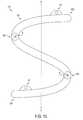
- the rod membercan have a pre-determined curve, and in one embodiment the curve can be complementary of a curve of a spine. Alternatively, the rod member can be substantially thin and flat. The rod member can also be bendable. In one embodiment the rod member can include a plurality of vertices disposed between the first and second mounting eyelets. For example, a first vertex can be disposed on one side of a longitudinal axis of the rod member and a second vertex can be disposed on an opposite side of the longitudinal axis of the rod member.
- the openings of the first and second mounting eyeletscan be configured to receive a screw therein such that a central axis disposed through a screw received by the first mounting eyelet is in a non-parallel position with respect to a central axis disposed through a screw received by the second mounting eyelet.
- the methodincludes inserting a rod member having first and second mounting eyelets through an opening proximate to a cervical spine, attaching the first mounting eyelet to a first vertebra in a cervical spine, and attaching a second mounting eyelet to a second vertebra in a cervical spine.
- the openingcan be located lateral or posterior-lateral to the cervical spine.
- Either or both of the mounting eyeletscan be offset from a longitudinal axis of the rod member.
- the methodcan include adjusting a length of the rod member between the first and second mounting eyelets.
- the methodcan also include adjusting a shape of the rod member between the first and second mounting eyelets.
- a second rod membercan be inserted through the opening that is proximate to the cervical spine.
- the second rod membercan be positioned such that the second rod member is substantially parallel to the first rod member.
- the second rod membercan then be attached to vertebrae in the cervical spine, for instance by attaching a first mounting eyelet of the second rod member to one vertebra and attaching a second mounting eyelet of the second rod member to another vertebra.
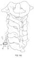
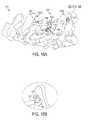
- FIG. 1is a schematic view of a human subject illustrating an exemplary location for an incision in which implants of the nature disclosed herein can be inserted into the subject;
- FIG. 2Ais a perspective view of an anterior and superior portion of one exemplary embodiment of a spinal implant that includes a cage member and a plate member;
- FIG. 2Bis a perspective view of a posterior and superior portion of the spinal implant of FIG. 2A ;
- FIG. 2Cis a perspective view of a posterior portion of the spinal implant of FIG. 2A ;
- FIG. 2Dis a perspective view of a proximal end of the spinal implant of FIG. 2A ;
- FIG. 2Eis a perspective view of an anterior portion of the spinal implant of FIG. 2A ;
- FIG. 2Fis a perspective view of an inferior portion of the spinal implant of FIG. 2A ;
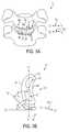
- FIG. 3Ais an anterior view of one exemplary embodiment of a spinal implant that includes a cage member, the implant being disposed between two adjacent vertebrae;
- FIG. 3Bis a top view of another exemplary embodiment of a spinal implant that includes a cage member and a plate member;
- FIG. 4Ais a top view of an exemplary embodiment of a spinal implant that includes a bend zone between a cage member and a plate member, and having a vertebral body disposed therebelow;
- FIG. 4Bis a top view of another exemplary embodiment of a spinal implant that includes multiple bend zones between a cage member and a plate member;
- FIG. 4Cis a top view of yet another exemplary embodiment of a spinal implant in which the plate member appended to the cage member is substantially flat;
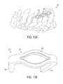
- FIG. 4Dis a top view of still another exemplary embodiment of a spinal implant in which the plate member appended to the cage member is generally V-shaped;
- FIG. 4Eis a top view of another exemplary embodiment of a spinal implant in which the plate member appended to the cage member is generally U-shaped;
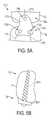
- FIG. 5Ais an anterior view of an exemplary embodiment of plate member of a spinal implant
- FIG. 5Bis a top schematic view of an exemplary embodiment of a fixation element being disposed in a spinal implant
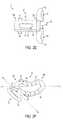
- FIG. 6Ais a distal perspective view of another exemplary embodiment of a spinal implant that is threaded and includes a tapered distal end;
- FIG. 6Bis a proximal perspective view of the spinal implant of FIG. 4A ;
- FIG. 6Cis a proximal view of the spinal implant of FIG. 4A ;
- FIG. 7is a distal perspective view of an exemplary embodiment of a spinal implant that is threaded and has a non-tapered distal end;
- FIG. 8is a perspective view of another exemplary embodiment of a spinal implant that includes a plurality of edges and spikes disposed around a circumference thereof;
- FIG. 9is a perspective view of yet another exemplary embodiment of a spinal implant that includes a plurality of spikes disposed around a circumference thereof;
- FIG. 10is a perspective view of still another exemplary embodiment of a spinal implant that is threaded and includes a plurality of fingers;
- FIG. 11Ais a schematic view of an exemplary embodiment of a spinal implant that includes a plurality of edges disposed around a circumference thereof before it is disposed between two vertebrae;
- FIG. 11Bis a schematic view of the spinal implant of FIG. 9A after it is disposed between two vertebrae;
- FIG. 12Ais a schematic view of another embodiment of a spinal implant that is threaded and is disposed between two vertebrae;
- FIG. 12Bis a detail view of the spinal implant of FIG. 10A ;
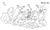
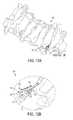
- FIG. 13Ais a perspective view of an exemplary embodiment of a spinal implant that includes lateral staples and is attached to a cervical region of a spine;
- FIG. 13Bis a perspective view of a lateral staple for use implantation in a cervical region of a spine
- FIG. 14Ais a perspective view of one exemplary embodiment of a spinal implant that includes a rod member having mounting eyelets;
- FIG. 14Bis a perspective view of the two spinal implants of FIG. 12A attached to a cervical region of a spine;
- FIG. 15is a schematic view of another exemplary embodiment of a spinal implant having a substantially S-shape
- FIG. 16Ais a perspective view of another exemplary embodiment of a spinal implant having a rod member coupled to a fixation element by way of a connector;
- FIG. 16Bis a detail view of a mounting eyelet of the spinal implant of FIG. 13A ;
- FIG. 17Ais a perspective view of still another exemplary embodiment of a spinal implant having a telescoping rod member and that is attached to a cervical region of a spine;
- FIG. 17Bis a perspective view of the spinal implant of FIG. 15A ;
- FIG. 18Ais a perspective view of an exemplary embodiment of a spinal implant having a locking mechanism disposed between two segments of a rod member and being attached to a cervical region of a spine;
- FIG. 18Bis a perspective view of the spinal implant of FIG. 16A from the posterior side;
- FIG. 18Cis a perspective view of the spinal implant of FIG. 16A from a lateral side;
- FIG. 19is a perspective view of another exemplary embodiment of a spinal implant having three mounting eyelets and being attached to a cervical region of a spine;
- FIG. 20is a perspective view of yet another exemplary embodiment of a spinal implant that is generally thin and flat and is attached to a cervical region of a spine;
- FIG. 21Ais a perspective view of still another exemplary embodiment of a spinal implant having a plurality of bends in its shape and that is attached to a cervical region of a spine;
- FIG. 21Bis a perspective view of the spinal implant of FIG. 19A .
- Devices and methods for fixing and/or stabilizing a location of bones in the cervical region of the spineare generally provided.
- the fixation approach disclosed hereinallows for delivery of spinal implants in a manner not typically relied upon for spinal fixation procedures.
- the devices and methodsallow for spinal implants to be implanted in a subject H from a lateral point of access LP.
- Implantscan be inserted through the lateral point of access at an angle that is substantially perpendicular to a sagittal plane S.
- implantscan be inserted from a posterior-lateral location.
- a point of accesscan be disposed in a direction that is posterior of the lateral point of access LP.
- an angle of insertion defined by a plane Ican be non-perpendicular to the sagittal plane S, preferably at an angle that is posterior to a plane P that is substantially perpendicular to the sagittal plane S.
- an angle A 1 formed between the plane P and the insertion plane Iis approximately 45 degrees in a posterior-direction to the plane P.
- the angle of insertion A 1can occur at any access point, including the lateral point of access LP as shown, or at a point of access that is posterior to the lateral point of access LP.
- the lateral or posterior-lateral approachcan be achieved in view of the present devices and methods without creating a substantial risk of causing undesirable damage to this sensitive area, which contains anatomical structures including the Carotid artery and Jugular vein.
- Some devicesinclude spinal implants configured to be disposed between adjacent vertebrae.
- Other devicesinclude spinal fixation elements that can be configured to extend from one vertebra to one or more additional vertebrae, even if those vertebrae are not adjacent.
- the methodsinclude surgical techniques that allow implants to be disposed through a small incision that is positioned lateral or posterior-lateral of a subject being treated.
- like-numbered components of the embodimentsgenerally have similar features, and thus within a particular embodiment each feature of each like-numbered component is not necessarily fully elaborated upon. Further, to the extent that linear or circular dimensions are used in the description of the disclosed devices and methods, such dimensions are not intended to limit the types of shapes that can be used in conjunction with such devices and methods.
- FIGS. 2A-2Fillustrate one exemplary embodiment of a spinal implant 10 , which is in the form of a lateral anterior fusion cage 20 .
- the disclosed lateral anterior fusion cagehas a design that lends itself to implantation in a subject's spine via a lateral or posterior-lateral surgical approach.
- the designis such that the implant maximizes the footprint of the implant component that is to reside between adjacent vertebral bodies while providing a large internal volume, which can serve as a graft chamber.
- the implantis asymmetric about a long axis of its cage.
- a plate member 50is asymmetric about a long axis L 1 of the cage member 20 such that the plate member is not equally sized and shaped on both sides of the long axis L 1 . In one illustrated embodiment, the plate member 50 is entirely on one side of the long axis L 1 .
- the cage member 20can closely match an anatomy of a central to posterior portion of a vertebral body and can therefore be disposed in the central to posterior portion of the cervical region of the spine.
- the implant 10can include both an elongate cage member 20 that is configured to be inserted between adjacent vertebrae and an optional plate member 50 that can be appended to the cage member 20 and that can be used to assist in securing the implant 10 at a desired location, such as on a lateral wall of one or more vertebral bodies.
- the cage member 20is generally oriented in a transverse plane of the body when implanted, extending laterally to medially between its proximal and distal ends 20 p , 20 d .
- the appended plate member 50when implanted, generally extends in the caudal to cephalad direction.
- the cage membercan be regarded to be of a generally rectangular shape in that it is elongate and has four sides. However, as explained below, each of the sides can be non-linear in shape. As a result, in some embodiments, the cage member 20 can be described as having a generally banana-like or canoe-like shape.
- the cage member 20can be elongate, and for reference purposes can be described as being oriented along a longitudinal axis L 1 in the transverse plane.
- the cage member 20can also be described as having an external surface that extends between the proximal and distal ends 20 p , 20 d , which is defined by a superior surface 22 , an inferior surface 24 , an anterior wall 26 , and a posterior wall 28 .
- One or more relief slits or openings 30can be formed in the external surface to, optionally, permit bone graft and/or bone growth-promoting material to be disposed therein, and thus facilitate integration of the implant within a subject.
- the distal end 20 d of the cage member 20can be configured for insertion between vertebral bodies of a subject and to optimize stable fixation within the subject. As shown, the distal end 20 d is of a rounded or bullet-shaped nature. Generally, the distal end 20 d serves as the leading edge of the implant 10 when disposing the implant 10 through an incision and into an intervertebral implantation site.
- the proximal end 20 p of the cage member 20is the trailing end of the spinal implant 10 and can include features adapted for anchoring the implant to a vertebral body, such as the plate member 50 . As shown, the proximal end 20 p can also tend to have rounded edges.
- the proximal end 20 pcan also include one or more features that enable the implant to be mated to an insertion instrument. An example of such a feature is threaded bore 32 ( FIG. 2D ).
- the surfaces 22 , 24 , 26 , and 28 that define the external surface of the cage member 20are sized and shaped in a manner that optimizes the placement and fixation of implant 10 between vertebral bodies in the cervical region of the spine, and particularly when the implant is positioned within the spine through lateral or posterior-lateral access.
- the surfaces 22 , 24 , 26 , and 28are configured to be complementary to the shape of the vertebral bodies at the site of implantation.
- the anterior wall 26is curved and is configured to be disposed at or proximate to an anterior portion of the vertebral body
- the posterior wall 28is also curved and is configured to be disposed at or proximate to a posterior portion of the vertebral body.
- a curve C AW of the anterior wall 26is generally convex ( FIG. 2B ) while a curve C PW of the posterior wall 28 is generally concave ( FIG. 2A ).
- Radii R CAW , R CPW of the curves C AW , C PWcan vary depending on the size of the implant. Generally, however, the radii R CAW , R CPW are substantially the same and can be in the range of about 7 millimeters to about 25 millimeters. In one embodiment the radii R CAW , R CPW can be about 10 millimeters.
- the superior and inferior surfaces 22 and 24are substantially linear.
- an implantcan have superior and inferior surfaces that are generally curved.
- the implant 10 ′ shown in FIG. 3Acan include a cage member 20 ′ with an external surface that includes a superior surface 22 ′, an inferior surface 24 ′, and an anterior wall 26 ′ that are each generally curved.
- the external surfacecan also include a posterior wall (not shown), which can also be generally curved.
- a curve C AW ′ of the anterior wall 26 ′is generally convex.
- a curve C S ′ of the superior surface 22 ′is generally concave while a curve C I ′ of the inferior surface 24 ′ is generally convex.
- the radii R CS ′, R CI ′ of the curves C S ′, C I ′can vary depending on the size of the implant, and can be in the range of about 10 millimeters to about 30 millimeters. In one embodiment the radii R CS ′, R CI ′ can be about 18 millimeters.
- the radii R CS ′, R CI ′can be substantially the same, in the illustrated embodiment the radii R CS ′, R CI ′ are different, with the inferior surface having a greater degree of curvature than the superior surface.
- the cage member 20 ′has an asymmetrically-curved, bullet-shaped distal end 20 d ′ that can be described as having a generally banana-like or canoe-like shape.
- the external surface of the implant 10 , 10 ′may include surface features that prevent migration and assist in maintaining a location of the spinal implant.
- the superior and inferior surfaces 22 , 22 ′ and 24 , 24 ′include a plurality of ridges 34 , 34 ′.
- Ridges 34 , 34 ′can take a variety of forms, as one skilled in the art will appreciate.
- the ridgescan be of a triangular cross section with the apex at a distal position and a one-way directional slant as shown for example in FIGS. 2C and 2E .
- the directional slantallows insertion of the implant but resists its removal.
- Other surface features known to those skilled in the artcan also be provided without departing from the spirit of the invention.
- the external surface of the implant 10 , 10 ′may also include a plurality of relief slits or openings 30 , 30 ′ to permit access to an internal volume within the implant.
- the internal volumemay be packed with bone graft and/or bone growth-promoting materials to enhance and expedite integration of the implant into a subject's body. While in the illustrated embodiment of FIGS. 2A-2F each of the superior surface 22 , inferior surface 24 , anterior wall 26 , and posterior wall 28 including openings 30 , in other embodiments only some of the surfaces or walls may include an opening(s), or even none of the surfaces or walls may include openings. Similarly, more than one opening can be formed on one or more sides of the external surface.
- FIG. 3Aillustrates an embodiment in which the implant 10 ′ of FIG. 3A does not include a plate member.
- a plate membercan assist in securing the implant at a desired location between vertebral bodies, the shape of the implant itself can provide sufficiently secure placement of the implant.
- the banana-like shape and asymmetrical curve of the implant 10 ′enables stable placement of the implant 10 ′ without the need for a plate member.
- FIGS. 2A-2Fillustrate an implant 10 that does include a plate member 50 disposed in proximity to the proximal end 20 p of the cage member 20 . While in the illustrated embodiment the plate member 50 is integrally formed with the proximal end 20 p , it can be appended to the proximal end 20 p in other ways known to those having skill in the art. By way of non-limiting examples, a plate member can be slidingly coupled to a cage member or removably and replaceably coupled to a cage member.
- the plate member 50generally extends in a direction that is opposite to that of the elongate direction of the cage member 20 . As shown in FIG. 2A , while the cage member 20 extends along a long axis L 1 , the plate member 50 extends in a long axis L 2 in a direction that is generally perpendicular to the direction of the longitudinal axis L 1 .
- the plate member 50can also be asymmetric with respect to the long axis L 1 . In the illustrated embodiment, the plate member 50 is entirely on one side of the long axis L 1 .
- the orientation of the plate member 50 and the cage member 20is such that when the cage member is parallel to the transverse axis of a subject's body, the plate member is not parallel to the sagittal plane. Rather, the plate member is anteriorly offset such that it is angled with respect to the sagittal plane.
- Such a constructionenables the plate member to be mounted to an anterior portion of the lateral wall of a vertebral body.
- a midpoint M of the plate member 50is disposed anterior to the long axis L 1 of the cage member 20 as shown in FIG. 2F .
- an angle A 2 formed by orientation of the plate member 50 and the orientation of the cage member 20can be less than 90 degrees ( FIG. 2F ), and is generally in the range of about 35 to about 80 degrees. In one embodiment the angle A 2 can be about 47 degrees.
- a configuration in which the midpoint M of the plate member 50 is disposed anterior to the long axis L 1 of the cage member 20can allow the plate member 50 to mount on a proximal lateral wall of the spine, anterior to the Carotid artery, within the C3 to C7 vertebrae range of the spine.
- the plate member 50is also curved along its short axis L S , as shown in FIG. 2A , to complement the shape of the lateral walls of the vertebrae upon which the plate member will mount. As shown in FIG. 2A , an internal surface 51 of the plate member 50 has a concave shape. Although a radius R CP of a curve C P of the plate member 50 can vary, it is generally in the range of about 10 millimeters to about 30 millimeters. In one embodiment the radius R cp is about 15 millimeters.
- the plate member 50can have a variety of shapes and sizes. In the illustrated embodiment the plate member 50 is generally rectangular and it extends in both the superior and inferior directions of the cage member 20 . Alternatively, it can extend in a single direction such that it mates to only one of the two adjacent vertebral bodies.
- the plate member 50can include one or more mating features to assist in mating the plate member 50 to vertebrae. As shown, the mating features can include a first bore 56 in a first wing 52 of the plate member 50 and a second bore 58 in a second wing 54 of the plate member 50 . Anchor members, such as screws complementary to the bores 56 , 58 , can then be used to secure the plate member 50 , and thus the spinal implant 10 .
- Mating features configured to be engaged by an insertion instrumentcan also be provided as part of the plate member.
- a threaded bore 32is provided as such a mating feature.
- the threaded bore 32 of the plate member 50can be engaged by an installation instrument (not shown) to assist in the insertion of the implant 10 .
- the illustrated embodimentalso includes further features for receiving insertion instruments.
- a receiving groove 62is provided that provides an indentation between the first and second wings 52 and 54 of the plate member 50 .
- the receiving groove 62includes a chamfer 64 that can be formed to be complementary to a shape of an insertion instrument.
- the plate membercan include one or more anti-migration features.
- one or more spikes, ridges, or other bone-engaging featurescan be disposed on the internal surface 51 of the plate member 50 . These features can be configured to engage an adjacent vertebral body to assist in maintaining the plate, and thereby the implant, at a desired location.
- FIG. 3Billustrates another embodiment of a spinal implant 10 ′′ having both a cage member 20 ′′ and a plate member 50 ′′.
- the external surface of the cage member 20 ′′is generally similar to the cage members 20 and 20 ′, although as shown the superior surface 22 ′′ includes more than one relief slit or opening 30 ′′ formed therein.
- the plate member 50 ′′is asymmetric with respect to a long axis L 1 ′′ of the cage member 20 ′′. That is, the plate member 50 ′′ is not equally sized and shaped on both sides of the long axis L 1 ′′.
- a curve C P ′′ of the external surface of the plate memberchanges as the curve C P ′′ moves from the posterior wall 28 ′′ to the anterior wall 26 ′′.
- a radius R CP ′′ of curvature of the curve C P ′′can be approximately in the range of about 5 millimeters to about 30 millimeters proximate to the posterior wall 28 ′′ and approximately in the range of about 5 millimeters to about 45 millimeters proximate to the anterior wall 26 ′′. In one embodiment the radius R CP ′′ is about 5 millimeters proximate to the posterior wall 28 ′′ and about 20 millimeters proximate to the anterior wall 26 ′′.
- the midpoint M′′ of the plate member 50 ′′is approximately aligned with the long axis L 1 ′′ of the cage member 20 ′′, although it can be offset anteriorly as described herein.
- Successive tangent linesas shown lines T 1 ′′ and T 2 ′′, are asymmetric to the long axis L 1 ′′.
- an angle A T ′′ formed by the tangent line and the long axis L 1 ′′decreases.
- the angle A T ′′decreases from an initial point (i.e., posterior most) adjacent to the posterior wall 28 ′′ in which the angle A T ′′ is in the range of about 80 degrees to about 95 degrees, to a point adjacent to the anterior wall 26 ′′ in which the angle A T ′′ is in the range of about 35 degrees to about 50 degrees.
- the angle A T ′′ for the tangent line T 1 ′′is about 90 degrees and the angle A T ′′ for the tangent line T 2 ′′ is about 45 degrees.
- the spinal implant 10is described as having two components, a cage member 20 and a plate member 50 , each being generally rectangular in shape and having particular curvatures that can be advantageous in certain instances, a variety of other shapes and curves can also be used in such cervical spine techniques without departing from the spirit of the invention.
- the cage memberis described as being of a generally rectangular shape and having walls and surfaces that are convex or concave, any walls and surfaces of the cage member can be virtually any shape, including generally flat, convex, or concave.
- the cage membercan take the form of a variety of other shapes.
- plate memberscan have a variety of configurations. Non-limiting examples of configurations of plate members that can be used in accordance with the present invention are provided in FIGS. 4A-4F .
- some embodiments of implants 10 ′′′, 10 ′′′′can include bend zones 53 ′′′, 53 ′′′′ associated with the connection between cage and plate members 20 ′′′, 20 ′′′′ and 50 ′′′, 50 ′′′′.
- the bend zones 53 ′′′, 53 ′′′′provide a level of flexibility or adjustability between the plate member 50 ′′′, 50 ′′′′ and the cage member 20 ′′′, 20 ′′′′ and can allow the plate member 50 ′′′, 50 ′′′′ to more accurately conform to an anatomy of a vertebral body, as shown in FIG. 4A with respect to the vertebral body V′′′.
- An angle A 3 formed by a proximal end 20 p ′′′ of the cage member 20 ′′′ and a tangent T P ′′′ of the plate membercan be in the range of about 10 degrees to about 50 degrees. In one embodiment the angle A 3 is in the range of about 30 degrees to about 45 degrees. As shown in FIG. 4B , bend zones 55 ′′′′ can also be formed within the plate member 50 ′′′′ itself, providing further flexibility and conformity to a desired surgical location.
- the plate membercan include a variety of different shapes and sizes. Non-limiting examples of plate member shapes are shown in FIGS. 4C-4F .
- a plate member 1650 of an implant 1610 shown in FIG. 4Cis substantially flat and mates to a cage member 1620 by way of a triangular coupling portion 1649 .
- a plate member 1650 ′ of an implant 1610 ′ in FIG. 4Dis substantially V-shaped and is mounted to a cage member 1620 ′ by way of a polygonal coupling portion 1649 ′.
- a plate member 1650 ′′ of an implant 1610 ′′ shown in FIG. 4Eis substantially U-shaped and is mounted to a cage member 1620 ′′ by way of a polygonal coupling portion 1649 ′′.
- a plate member 1650 ′′′ of an implant 1610 ′′′ shown in FIG. 4Fis substantially curved and is mounted to a cage member 1620 ′′′ by a flexible coupling portion 1649 ′′′. Any or all of these embodiments can include bend zones, like the bend zones 1653 ′′′ of the implant 1610 ′′′ of FIG. 4F , and can include characteristics and features of the other implants described herein.
- a proximal end of a plate membercan also have a variety of shapes in addition to the generally rectangular shape illustrated in FIGS. 2A-2F .
- a proximal end 1750 p of a plate member 1750 of an implant 1710can be generally triangular.
- a superior end 1750 s of the plate member 1750includes one bore 1756 while an inferior end 1750 i includes two bores 1758 .
- Anchoring elements 1770that are configured to be disposed in the bore 1756 , 1758 , can engage adjacent vertebrae V A and V B .
- an anchoring element 1870can cause bilateral fixation by being fixed through a plate member 1850 at both a proximal end V P of a vertebral body V, i.e., the first cortex, and a distal end V D of a vertebral body V, i.e., the cortical wall, the fixation element 1870 terminating past the cortical wall of the same vertebral body V.
- the implantcan be made from any number of biologically-compatible materials used to form spinal implants, including materials that are partially or fully bioresorbable.
- Exemplary materialsinclude titanium, titanium alloys, titanium mesh, polyether ether ketone (PEEK), reinforced PEEK, and Nitinol®.
- an incision or delivery aperture in the range of approximately 25 millimeters to approximately 35 millimeterscan be formed in an area near the cervical region of the spine.
- the incisionis formed at a location that is lateral or posterior-lateral of a subject, as illustrated in FIG. 1 .
- the devices and methodsallow for spinal implants to be implanted in a subject H from a lateral point of access LP such that the point of insertion is substantially perpendicular to the sagittal plane S.
- the point of insertioncan be posterior of the lateral point of access LP, for example up to about 45 degrees posterior to the lateral point of access LP.
- the point of insertioncan be anterior to a lateral point of access.
- a surgeoncan approach anterior to the Carotid artery and the Jugular vein and can retract a sheath used to insert the implant posterior following insertion.
- an implantcan be inserted through the incision and to a desired implant location.
- an access portcan be inserted into the incision to form an insertion channel and the implant can be inserted therethrough and placed at a desired implant location.
- the desired implant locationis in the cervical region of the spine, preferably between any two of the vertebrae in the C3 through C7 region, and more particularly is configured to be disposed between the C4 and C5 vertebrae.
- the distal end of the cage membercan first be inserted into the space between the desired vertebrae, and then the implant can be rotated to the desired implant location.
- the cage membercan fill about one-third to about two-thirds of the footprint of a vertebral body.
- the implantis shaped to match the contours of the desired implant location.
- the superior and inferior surfaces 22 , 22 ′ and 24 , 24 ′are configured to substantially match the anatomy of a central to posterior portion of adjacent vertebral bodies such that the implant 10 , 10 ′ can be rotated to and then implanted at a central to posterior portion of the adjacent vertebral bodies.
- This implant locationcan be desirable in order to successfully navigate the uncinate processes.
- the anterior wall 26 , 26 ′ of the cage member 20 , 20 ′can be substantially aligned with the curve of the anterior portions of the vertebrae.
- the implant 10 , 10 ′can be implanted at an angle with respect to a spine.
- the implant 10 ′can be placed at an angle with respect to the transverse axis at a range between about 1 degree and about 89 degrees, and more preferably between about 30 degrees and about 45 degrees.
- the anglecan be created during the act of inserting the implant through the incision, or any time thereafter, including at the site of the vertebral bodies.
- the plate member 50can be positioned so that it is adjacent to the vertebrae, closer to the anterior portion of the spine. The plate member 50 can then be fixed to one or both of the vertebrae such that the midpoint M of the plate member 50 is disposed anterior to the long axis L 1 of the cage member 20 . Bone graft or bone growth-promoting material can be incorporated into the cage member before, during, or after insertion is complete.
- FIGS. 6A-12BAnother spinal implant for use in treatment of the cervical region of the spine, referred to herein as an intra-facet fusion screw, is illustrated in FIGS. 6A-12B .
- the screws and staplescan be used by themselves as spinal implants, and are designed to be implanted directly between two facets between the diarthrodial surfaces of the facet joint.
- the screw 110can include a body portion 120 and a head portion 150 .
- the body portion 120can be generally cylindrical, hollow, and can include one or more relief slits or openings 130 in its surface to allow bone graft or bone growth-promoting materials to be disposed therein.
- there are four elongate openings 130although the number, size, and shape of the openings can vary across different embodiments, as will be appreciated by a person skilled in the art.
- a bore 132 extending through the body portion 120can be any shape, and the shape need not match the shape of the body portion 120 . However, in the illustrated embodiment the bore 132 is generally cylindrical and extends from the head portion 150 all the way through a distal end 120 d of the body portion 120 .
- the body portion 120can have threads 134 formed on an external surface, allowing the screw 110 to be more easily placed between opposed superior and inferior surfaces of the facet joint. Further, the threads 134 can also provide additional grooves on which bone graft and bone growth-promoting materials can be disposed. In the illustrated embodiment the distal end 120 d is tapered, which provides additional assistance in placing the screw 110 in a desired location.
- the body portion 120can also be configured to be expandable, which can assist in positioning the screw 110 in a desired location and subsequently holding the screw 110 in place. While a person skilled in the art will recognize a number of features that can be incorporated into the screw 110 to make it expandable, in some embodiments the relief slits or openings 130 themselves can provide that capability. In other instances, an expandable material can be used as part of the structure of the screw 110 .
- a diameter of the head portion 150can generally be greater than a diameter of the body portion 120 .
- the screw 110can be stopped at a desired location by abutting a distal surface 152 of the head portion 150 against bone near the desired location.
- a bore 160 of the head portion 150 that corresponds with the bore 132 of the body portion 120can also include additional features to assist in mating with insertion instruments. As shown, a hex-screw head having a series of six grooves 162 is provided in the bore of the head portion to allow a similarly-shaped insertion instrument to engage the screw 110 for implantation.
- the head portion 150is illustrated as being generally cylindrical or spherical, in some embodiments the head portion can be configured to have a shape that is complementary to a shape of the facet against which it is designed to rest.
- the implantcan be made from any number of biologically-compatible materials used to form spinal implants, including materials that are partially or fully bioresorbable.
- Exemplary materialsinclude titanium, titanium alloys, polyether ether ketone (PEEK), reinforced PEEK, and Nitinol®.
- PEEKpolyether ether ketone
- Nitinol®Nitinol®
- different portions of the screwmay be made of different materials.
- the head portionmay be made from a different material than the body portion or a distal end of the body portion may be made from a different, possibly harder material, than the remainder of the body portion.
- a diameter of the body portion 120is approximately in the range of about 5 millimeters to about 19 millimeters while a diameter of the head portion 150 is approximately in the range of about 7 millimeters to about 22 millimeters.
- the size of the diameter of the body portion 120 and the size of the diameter of the head portion 150can depend on each other, and in one embodiment the diameter of the body portion is approximately in the range of about 5 millimeters to about 6 millimeters and the diameter of the head portion is approximately in the range of about 7 millimeters to about 8 millimeters. Further, in some embodiments, a length of the body portion 120 can be approximately in the range of about 7 millimeters to about 30 millimeters.
- the length of the body portion 120is approximately in the range of about 10 millimeters to about 12 millimeters. Other shapes and designs can be used depending on the location that the screws 110 are intended to be implanted. Still further, while the illustrated embodiment shows the screw 110 as a unitary component, in other embodiments the body portion 120 can be disengaged from the head portion 150 or the body portion 120 can be broken apart into two or more sections.
- FIGS. 7-10A number of other embodiments of facet screws 210 , 310 , 410 , and 510 are also provided in FIGS. 7-10 .
- the screw 210 of FIG. 7includes a body portion 220 having a plurality of threads 234 disposed thereon, a bore 232 extending therethrough, and a plurality of elongate relief slits or openings 230 formed therein.
- a head portion 250is integrally formed with the body portion 220 .
- the screw 210 of FIG. 7differs from the screw 110 of FIGS. 6A-6C because a distal end 220 d of the body portion 210 of FIG. 7 is not tapered.
- FIG. 8illustrates another embodiment of an intra-facet screw 310 .
- the screw 310includes a body portion 320 having a bore 332 extending therethrough and a head portion 350 .
- a diameter of the head portion 350can be larger than a diameter of the body portion 320 .
- the difference between the diameters of the body and head portions 320 and 350 in the screw 310is not as pronounced as in embodiments shown in FIGS. 6A-6C and 7 .
- the body portion 320is not threaded. Instead, a plurality of edges 334 , 336 is formed on the body portion 320 .
- edges 334extend along most of the length of the body portion 320 , while other edges 336 are formed on either end of elongate openings 330 in the body portion 320 .
- any number of relief slits or openings 330can be formed in the body portion 320 .
- a distal end 320 d of the body portion 320is tapered, and although in the illustrated embodiment the edges 334 , 336 do not extend onto the tapered distal end 320 d , in other embodiments the edges 334 , 336 can extend onto the tapered distal end 320 d .
- a plurality of spikes 338can be formed around a circumference of the screw 310 such that the spikes 338 extend from the head portion 350 and onto the body portion 320 . The spikes 338 can assist in maintaining a location of the screw 310 as it is implanted in a desired location.
- FIG. 9Yet another embodiment of an intra-facet screw 410 is illustrated in FIG. 9 .
- the screw 410 of FIG. 9which is similar to the screw in FIG. 7 , includes a body portion 420 having a bore 432 extending therethrough, a plurality of elongate relief slits or openings 430 formed in the body portion 420 , a tapered distal end 420 d , and is not threaded.
- a head portion 450includes a plurality of spikes 438 around a circumference of the screw 410 and that extend onto the body portion 420 .
- FIG. 10Still a further embodiment of an intra-facet screw 510 is illustrated in FIG. 10 .
- the screw 510 of FIG. 10is more closely akin to the screws 110 and 210 of FIGS. 6A-6C and 7 because the screw 510 includes a body portion 520 having a bore 532 extending therethrough and threads 534 formed thereon, as well as a head portion 550 that has a diameter that is significantly larger than a diameter of the body portion 520 .
- the body portion 520does include a plurality of relief slits or elongate openings 530 formed therein, the openings 530 do not close at the distal end 520 d . This results in the formation of an elongate body that includes four fingers 540 .
- This embodimentcan provide additional flexibility in implanting the screw 510 in a desired location because the distal end 520 d can be easier to manipulate in and out.
- FIGS. 11A and 11BOne method of using implants of the nature illustrated and described with respect to FIGS. 6A-10 is illustrated by FIGS. 11A and 11B .
- an intra-facet screw 610 having a body portion 620 and a head portion 650can be disposed adjacent of a desired implant location in the cervical region of the spine.
- the screw 610can be placed at a desired location in a manner similar to the methods described above for implanting the implants of FIGS. 2A-3 .
- a lateral or posterior-lateral incisioncan be formed in an area near the cervical region of the spine and the intra-facet screw 610 can be inserted through to the cervical region of the spine directly, or through a port placed in the incision.
- An angle of insertioncan be substantially perpendicular to the sagittal plane of a subject, or it can be at an angle posterior to perpendicular to the sagittal plane, as shown for example in FIG. 1 .
- the intra-facet screw 610After the intra-facet screw 610 is in the vicinity of its desired implantation site, it can be pushed between two adjacent facet joints, as shown facet joints F 6 and F 7 , until a distal surface of the head portion 650 of the screw 610 is flush against a portion of the bone. In other embodiments the screw can be inserted even further such that a proximal surface of the screw is flush with the bone or passes beyond the surface of the bone.
- Bone graft or bone growth-promoting materialcan be added to the screw 610 after insertion is complete, for instance through a bore 632 . In embodiments in which the body portion 620 is threaded or in which there are openings formed in the body portion 620 , the bone graft or bone growth-promoting material can be associated with those portions before, during, or after implantation.
- FIGS. 12A and 12Billustrate another intra-facet screw 710 disposed in a cervical region of the spine. Implantation of this screw 710 can be performed in a manner similar to the manner described with respect to FIGS. 11A and 11B . As shown, threads 734 of a body portion 720 can engage the adjacent facet joints, as shown facet joints F 6 and F 7 , when the screw 710 is driven into the space between the F 6 and F 7 facet joints and the screw 710 comes to rest when a head portion 750 engages the bone.
- the screw 710includes a hex-head 762 such that a hex-shaped insertion instrument can be used to drive the screw 710 into its desired location.
- any areas not already filled with bone graft or bone growth-promoting materialcan be filled with such a material, including a bore 732 extending through the body portion 720 , openings 730 in the body portion, and the threads 734 .
- FIGS. 13A and 13Billustrate another embodiment of a spinal implant 810 .
- the implant 810includes lateral staples 820 configured to be disposed between lamina of the spine, or adjacent structures such as the spinous process.
- the staplescan include an elliptically-shaped central portion 830 and engaging arms 850 .
- the staples 820can be made of a temperature-sensitive material, such as Nitinol®, such that the staples can assume a desired configuration upon delivery between adjacent vertebrae.
- the central portion 830can expand and the engaging arms 850 can close.
- the staple 820is delivered so that the engaging arms 850 are disposed partially in adjacent lamina.
- the central portion 830expands and the engaging arms move toward each other, causing the adjacent lamina to be pulled together.
- a length of a staple from one arm to the other armcan be about 10 millimeters to about 50 millimeters. In one embodiment it can be about 12 millimeters and in another embodiment it can be about 20 millimeters Likewise, a length of an arm itself can vary, and can be in the range of about 6 millimeters to about 20 millimeters. In one embodiment a length of one arm can be about 6 millimeters and a length of another arm can be about 10 millimeters.
- the staplescan be asymmetric such that the length of one arm is different than the length of the second arm of the same staple, while in other embodiments the lengths of each arm can be substantially equal. Further details about staples that can be adapted for use as a spinal implant in view of the teachings contained herein are found in U.S. Pat. No. 5,779,707, the contents of which is incorporated by reference in its entirety.
- the staplescan first be brought to a temperature at which its arms are open for implantation.
- the staplesare kept for at least two hours at a maximum temperature of about 0° F. ( ⁇ 18° C.).
- the implantation sitecan be prepared to receive the staples. This can include using any number of guides, drills, and wires, among other instruments, to prepare vertebral bodies for receiving the staples. For example, temporary pins can be used to prevent displacement of structures at or adjacent to the implantation site. Likewise, guides can be used to place the vertebral bodies at an ideal location for receiving the staples.
- one of the staplescan be inserted to the surgical location and implanted such that a first arm of the staple is driven into a portion of a first vertebral body and a second arm of the staple is driven into a portion of a second vertebral body.
- a surgical stapler, impactor, such as a Memory arthrodesis impactor, or any other known tool for applying staples,can be used to implant the staples.
- any number of instrumentscan be used to assist with the insertion of the staples, such as guides and pins.
- any instruments used to assist with the preparation of the implantation site or the implantation of the staplecan be removed.
- the armscan be actuated toward a central portion of the staple to close the arms. This can result naturally from the temperature of the surgical location, which is higher than the starting temperature of the staples, or a surgeon can control the temperature at the surgical site to assist in the actuation of the arms. Actuation of the arms results in the vertebral bodies in which the arms are engaged being drawn toward each other. Other staples can be implanted in a similar manner.
- the staples 810are implanted in adjacent vertebral bodies, in other embodiments the staples can span across two or more vertebral bodies.
- additional methods for operating staples of the nature disclosed hereincan be found in the Memory Staple Surgical Technique, a publication distributed by DePuy Spine, Inc., a Johnson & Johnson company, the contents of which is incorporated by reference in its entirety. Although the techniques described in that publication are generally directed to implantation in a subject's foot, a person skilled in the art would be able to adapt those techniques for use in vertebral bodies based on the disclosures contained herein.
- spinal fixation elementssuch as rod members, capable of extending across a plurality of vertebral bodies.
- spinal stabilization memberscapable of extending across a plurality of vertebral bodies.
- the spinal stabilization members of the present inventionwhich are illustrated in FIGS. 14A-21B , are particularly useful because they provide the mobility and flexibility of using a rod while also providing the benefit of having multiple fixation points.
- Spinal fixation elements disclosed hereinavoid some of the drawbacks associated with previously known spinal fixation elements, which have limited placement flexibility due to the need to affix them to the spine with separate plate members or other attachment means.
- fixation points that are formed on the rod itselfdramatically increases the number of points at which the rod members can be fixed.
- the spinal fixation elementsbecome substantially more versatile for use in the cervical region of the spine.
- the number of possible implant locationsincreases, and thus, the number of possible rod designs increases.
- FIGS. 14A and 14BOne exemplary embodiment of a spinal implant 910 that includes a rod member 920 for use in treating the cervical region of the spine is illustrated in FIGS. 14A and 14B .
- FIG. 14Aillustrates a single, elongate rod member 920
- FIG. 14Billustrates two rod members 920 implanted in a cervical region of a spine.
- Anchor members 970such as bone screws, can be used to secure the rod members 920 at desired locations in one or more of the vertebrae.
- the rod member 920is generally elongate between its proximal and distal ends 920 p , 920 d . While the rod member 920 can be substantially straight, in the illustrated embodiment the rod member 920 is curved at least in one plane. Those skilled in the art will appreciate that the curve of the rod member can take any shape needed to address a patient's condition. In instances in which a patient suffers from lordosis or another condition, a curve can be substantially similar to a curve of the spine that results from lordosis or another condition. In some embodiments, a plurality of shorter rod members can be used to allow for a profile of a spine to be biomechanically matched.
- a longer rod membercan be designed to biomechanically match a spine profile.
- a radius R R of a curve C R of the rod member 920can be in the range of about 0 millimeters to about 500 millimeters, and in one embodiment the radius R R is about 4 millimeters.
- the radius of the curve of a spinal fixation elementmay change throughout its distribution because the curve can be asymmetric.
- the curvecan be pre-determined.
- the rod member 920can include some flexibility or malleability to allow it to be shaped as desired by a surgeon at the time of a surgical procedure.
- the rod member 920can be fully bendable so it can be formed into any desired shapes across its length.
- the rod member 920is substantially S-shaped, while in another embodiment it is substantially Z-shaped. Any number of shapes can be achieved by the rod member 920 .
- the rod member 920can have any size. It can be sized for use in the cervical region of the spine, and more particularly to extend between any length between the C1 and C7 vertebrae. As shown in FIG.
- the rod member 920extends between the C3 and the C7 vertebrae.
- the length of the rod membercan be in the range of about 20 millimeters to about 250 millimeters, and in one embodiment can be about 35 millimeters
- the rod membercan have a variety of thicknesses.
- the rod membercan have a thickness in the range of about 3 millimeters to about 20 millimeters, or in the range of about 3 millimeters to about 5.5 millimeters, and in one embodiment can be about 4 millimeters.
- the rod membercan also have a variety of cross sectional shapes, including circular, ovoid, square, rectangular, triangular, etc.
- the rod member 920can include features configured to assist with its implantation at a desired surgical location.
- the distal end 920 dincludes a V-shaped notch 932 , which is complementary to a distal end of an insertion instrument such that the insertion instrument can engage the rod member 920 at the V-shaped notch 932 to direct the rod member 920 to a desired location.
- the notch 932is V-shaped, any number of shapes and configurations can be used to assist in mating an insertion instrument with the rod member 920 .
- a person skilled in the artwill recognize other ways by which the notch 932 can be used to insert the rod member 920 to a desired surgical location.
- the rod member 920can also include one or more mounting eyelets 950 , 951 . As shown, the rod member 920 includes two mounting eyelets—the first mounting eyelet 950 is disposed in proximity to the distal end 920 d and the second mounting eyelet 951 is at the proximal end 920 p .
- the eyelets 950 , 951can be located anywhere along a length of the rod member 920 .
- an eyeletcan be located at each of the proximal and distal ends 920 p , 920 d , while in other embodiments an eyelet can be located in proximity to a distal end 920 d and a second eyelet can be located in proximity to a proximal end 920 p , but neither being at a terminal end of the rod member 920 . Eyelets can even be located centrally along a length of the rod member 920 . In some embodiments, eyelets can be slidably coupled to the rod member such that the location of the eyelets can be moved to desired locations at a surgical site.
- the mounting eyelets 950 , 951can either be in-line with a longitudinal axis L R of the rod member 920 or offset from the longitudinal axis L R .
- FIGS. 14A and 14Billustrate that the second mounting eyelet 951 is approximately in-line with the longitudinal axis L R , while the first mounting eyelet 950 is offset from the longitudinal axis L R .
- a central axis C 1 of the second mounting eyelet 951intersects the longitudinal axis L R while a central axis C 0 of the first mounting eyelet 950 is offset from the longitudinal axis L R .
- Either or both of the eyelets 950 , 951can be selectively located approximately in-line with the longitudinal axis L R or offset from the longitudinal axis L R .
- any number of eyeletscan be used in conjunction with the elongate rod member 920 in any number of configurations with respect to the eyelets being approximately in-line or offset from the longitudinal axis of the rod member.
- each eyeletcan serve as a vertex of the desired shape.
- a rod member 920 ′is substantially S-shaped, as illustrated in FIG.
- a first and third mounting eyelet 950 ′, 953 ′can be disposed on one side of a central axis CA′ that bisects the rod member 920 ′ and a second and fourth mounting eyelet 951 ′, 955 ′ can be disposed on the other side of the central axis CA′.
- the first and second mounting eyelets 950 ′, 951 ′are offset with respect to the rod member 920 ′, while the third and fourth mounting eyelets 953 ′, 955 ′ are substantially in-line with respect to the rod member 920 ′.
- first and second mounting eyelets 950 ′, 951 ′are in proximity to distal and proximal ends 920 d ′, 920 p ′, respectively, while the third and fourth mounting eyelets 953 ′, 955 ′ are disposed approximately at vertices A and B, respectively.
- other combinations of locations of eyeletscan also be used with the rod member 920 ′.
- the eyelets 950 , 951can be configured to receive a variety of anchoring members (e.g., hooks, bolts, wires, screws, anchors, etc.), but as shown the eyelets 950 , 951 each include a circular bore 950 b , 951 b so that anchoring members 970 , such as screws, can be disposed therethrough.
- the mounting eyelets 950 , 951can be configured such that anchoring members disposed therein need not be oriented to extend parallel to each other. That is, the eyelets can be designed to allow for polyaxial movement of the anchor members engaged therein.
- an internal surface of the eyeletscan be substantially spherical so as to correspond with a spherical head (not shown) of the anchor element such that the head can rotate relative to the eyelet as in a ball-in-socket joint.
- FIGS. 15-21Billustrates a rod member 920 ′ having an S-shape having at least one vertex and having eyelets 950 ′, 951 ′, 953 ′, and 955 ′ disposed on either side of the central axis CA′ that bisects the implant 910 ′.
- FIGS. 16A and 16Billustrate an embodiment of a spinal fixation element 1010 in which a rod member 1020 is used in conjunction with a connector 1080 and an anchor member 1090 .
- the rod member 1020includes an offset mounting eyelet 1050 in proximity to a distal end 1020 d of the rod member 1020 , an in-line mounting eyelet 1051 at a proximal end 1020 p of the rod member 1020 , and a third mounting eyelet 1053 disposed between the eyelets 1050 and 1051 .
- the third eyelet 1053is an in-line mounting eyelet that is slidably mounted upon the rod member 1020 .
- the third eyelet 1053is configured to couple to the anchor member 1090 that is disposed adjacent to and offset from the rod member 1020 by way of the connector 1080 , enabling the rod member 1020 to be secured to the spine at a location intermediate the eyelets 1050 , 1051 . This can be useful, for example, when part of a vertebra has been removed or lacks sufficient strength to receive an anchor member.
- the connector 1080extends between a connector housing 1092 of the anchor member 1090 and the eyelet 1053 .
- the connector 1080can be secured within the housing 1092 by a set screw 1094 and is secured to the third eyelet 1053 and the rod member 1020 by a set screw 1096 .
- the anchor member 1090can secure the connector housing 1092 to a sound portion of the vertebra and, when properly positioned, the eyelet 1053 can be secured in its desired location using the set screw 1096 .
- a person skilled in the artwill recognize a variety of ways in which the slidable third eyelet 1053 can be secured to a vertebra offset from the rod member 1020 by way of the connector 1080 and anchor member 1090 .
- one or more of the mounting eyelets 1051can include a pivoting or swivel feature.
- a pivoting or swivel featureprovides additional flexibility in achieving a desired location for the rod member 1020 .
- a screw 1070can be selectively loosened to allow the rod member 1020 to move or swing to a desired location, and then the screw 1070 can be selectively tightened to engage the rod member 1020 and fix its location. Pivoting or swivel features of this nature can be incorporated to any of the mounting eyelets disclosed herein, and at any location across a length of the rod members.
- FIGS. 17A and 17Billustrate an implant 1110 in the form of a spinal fixation element having a telescoping feature, thereby allowing a length of a rod member 1120 to be selectively adjusted.
- a first segment 1119 of the rod member 1120can have a bore with an internal diameter that is larger than an outer diameter of a second segment 1121 .
- the first segment 1119can receive the second segment 1121 , enabling the first and second segments 1119 , 1121 to slide with respect to each other such that the length between first and second mounting eyelets 1150 , 1151 , and thus the distance between distal and proximal ends 1120 d , 1120 p of the rod member 1120 , can be adjusted.
- the first segment 1119is coupled to first mounting eyelet 1150 by way of a threaded portion 1123 .
- the first segment 1119can be rotated around the threaded portion 1123 to form different lengths of the rod member 1120 .
- the location of the first segment 1119can be fixed by a locking nut 1227 disposed on the threaded portion 1123 between the first segment 1119 and the first mounting eyelet 1150 .
- the first segment 1119can be selectively unlocked with respect to the threaded portion 1123 and the second segment 1121 and subsequently adjusted as desired.
- the anchor members 1170 disposed in the first and second mounting eyelets 1150 , 1151may extend at different angles due to the polyaxial seating of the anchor members within the eyelets 1150 , 1151 .
- FIGS. 18A-18CAnother embodiment of a telescoping spinal fixation element implant 1210 that includes a rod member 1220 having an adjustable length is shown in FIGS. 18A-18C .
- a first mounting eyelet 1250is secured to the spinous process of a first vertebra, C2
- a second mounting eyelet 1251is secured to the spinous process of a second vertebra, C7.
- each of the two mounting eyelets 1250 and 1251is secured to the respective C2 and C7 vertebrae by way of brackets 1255 , 1257 and rods 1259 , 1261 .
- the brackets 1255 , 1257can be disposed around the spinous processes and the rods 1259 , 1261 can be coupled to the brackets 1255 , 1257 and eyelets 1250 , 1251 , passing through the spinous processes of the C2 and C7 vertebrae.
- One or more anchor members 1270can be inserted proximate to the mounting eyelets 1250 , 1251 to further secure the location of the eyelets 1250 , 1251 with respect to the spine.
- the rod member 1220includes two separate segments 1219 , 1221 disposed between the first and second eyelets 1250 , 1251 and an adjustment mechanism 1265 is provided between the two segments 1219 , 1221 .
- the adjustment mechanism 1265includes a locking member having a housing 1267 . Threaded ends 1217 , 1223 of each of the two segments 1219 , 1221 are coupled to opposite ends of the housing 1267 , and a portion of the threaded ends 1217 , 1223 can be disposed within the hollow interior of the housing 1267 .
- Locking nuts 1227 , 1229can be disposed around the segments 1219 , 1221 on the outside of the housing 1267 . As will be appreciated by a person skilled in the art, the locking nuts 1227 , 1229 can be rotated to selectively lock and unlock the segments 1219 , 1221 to form a rod of a desired length.
- FIG. 19illustrates yet another embodiment of a spinal implant 1310 in which the spinal fixation element is a rod member 1320 that includes three mounting eyelets 1350 , 1351 , and 1353 .
- eyelet 1351is disposed at a proximal end 1320 p of a rod member 1320 and is configured to be generally stationary.
- a bore 1351 b of the eyelet 1351is configured to receive an anchor member 1370 therein, and the size of the bore 1351 b is generally complementary to a size of the anchor member 1370 to be disposed therein.
- the eyelet 1351is integrated within the rod member 1320 .
- Mounting eyelet 1350is shown disposed proximate to a distal end 1320 d of the rod member 1320 and it is coupled to the rod member 1320 by way of a coupling portion 1355 disposed around at least a portion of the rod member 1320 .
- the position of the coupling portion 1355is adjustable as it can slide proximally and distally along the rod member to optimize the point of attachment to a vertebral body.
- the rod member 1320can be substantially rigid, and it can include mating features, such as ridges 1334 , that allow the coupling portion 1355 to more easily grip the rod member 1320 .
- the diameter of a bore 1350 b of the eyelet 1350can be substantially larger than a diameter of an anchor member 1371 disposed therein.
- This configurationallows for fine adjustment of the relative position of the rod member 1320 and the anchor member 1371 when the anchor member 1371 is not fully seated within the bore 1350 b . That is, the rod member 1320 can be slid in a direction toward and away from mounting eyelet 1350 . When the anchor member 1371 is not fully secured in the eyelet, the anchor member 1371 can be rotated in a clockwise direction to engage the fixation element 1371 with the bore 1350 b . This causes the coupling portion 1355 to tighten around the rod member 1320 , thereby locking the first mounting eyelet 1350 and the rod member 1320 in place to set the new location of the rod member 1320 .
- the diameter of a bore 1353 b of the mounting eyelet 1353is also larger than the diameter of an anchor member 1373 disposed therein and the third mounting eyelet 1353 is coupled to the rod member 1320 by way of a coupling portion 1357 disposed around at least a portion of the rod member 1320 .
- FIGS. 20, 21A, and 21Billustrate two further embodiments of implants 1410 and 1510 having differently shaped rod members 1420 and 1520 .
- the rod member 1420is substantially thin and flat. In some embodiments the rod 1420 can be laminar in nature.
- the rod member 1420 illustrated in FIG. 20includes two mounting eyelets 1450 and 1451 , the first eyelet 1450 located in proximity to a distal end 1420 d of the rod member 1420 and the second eyelet 1451 located in proximity to a proximal end 1420 p of the rod member 1420 .
- each of the two eyelets 1450 , 1451is offset with respect to a longitudinal axis L F of the rod member 1420 , however, in other embodiments, one or more eyelets can be substantially in-line with the longitudinal axis L F .
- Anchor members 1470can be disposed in bores of the eyelets 1450 , 1451 .
- FIGS. 21A and 21Billustrate a spinal implant 1510 having a rod member 1520 that includes a plurality of bends B 1 , B 2 , and B 3 .
- the anatomy of the spine in which the rod member 1520 is disposedincludes three vertebrae, C4, C5, and C6, in which the spinous process is cut away.
- the rod member 1520bends closer to these portions of the vertebrae to provide additional stability.
- a distal end 1520 d of the rod member 1520includes a first mounting eyelet 1550 and is mounted to the spinous process of the C3 vertebra using an anchor member 1570 .
- a proximal end 1520 p of the rod member 1520includes a second mounting eyelet 1551 and is mounted to the spinous process of the C7 vertebra using an anchor member 1570 .
- the eyelet 1550is offset with respect to a longitudinal axis L S of the rod member 1520 and the eyelet 1351 is substantially in-line with respect to the longitudinal axis L S .
- a first, distal bend B 1is provided proximate to the spinous process of the C3 vertebra, and then a second, intermediate bend B 2 is provided proximate to the C4 and C5 vertebrae.
- a third, proximal bend B 3is provided proximate to the C6 and C7 vertebrae so the rod member 1520 can bend in a superior direction and terminate at the second eyelet 1351 , proximate to the posterior portion of the C7 vertebra.
- any materialcan be used to form the spinal fixation elements disclosed in FIGS. 14A-21B , including biologically-compatible materials used to form spinal fixation elements and partially and fully bioresorbable materials.
- materials suitable for useinclude titanium, titanium alloys, polyether ether ketone (PEEK), and reinforced PEEK.
- PEEKpolyether ether ketone
- materials that include a shape metal alloy, such as Nitinol®can be desirable.
- Different portions of the length of spinal fixation elementscan be made from different materials to achieve different desired results.
- a portion of the spinal fixation elementcan be made from a more flexible material while another portion of the spinal fixation element can be made from a more rigid material. Materials can be mixed and matched as desired.
- an incision or delivery aperturecan be formed proximate to a cervical region of the spine in a manner similar to the described incision formation with respect to the implants of FIGS. 2A-3 , and the implant are is prepared as needed.
- a lateral or posterior-lateral incisioncan be formed in an area near the cervical region of the spine and a rod member 920 can be inserted through to the cervical region of the spine directly or through an access port placed in the incision.
- An angle of insertioncan be substantially perpendicular to the sagittal plane of a subject, or it can be at an angle posterior to perpendicular to the sagittal plane, as shown for example in FIG. 1 .
- the embodiment illustrated in FIG. 14Bis discussed herein, although the methods can be used with respect to any of the spinal implants disclosed herein.
- the rod member 920can be inserted at a position that is lateral to or posterior-lateral to the cervical region of the spine. The rod member 920 can then be positioned proximate to the cervical region of the spine at a desired location. Eyelets 950 , 951 of the rod member 920 can be aligned with the vertebrae in which they will be delivered. In the illustrated embodiment, the first mounting eyelet 950 is disposed proximate to the C3 vertebra and the second mounting eyelet 951 is disposed proximate to the C7 vertebra. Then each of the mounting eyelets 950 , 951 can be attached to the respective vertebrae, C3 and C7, for example by using anchor members 970 . This can be accomplished in any order, including simultaneously if the fixation element delivery device is designed in such a manner.
- a second rod member 920can also be introduced to the cervical region of the spine in the same manner. As shown in FIG. 14B , the second rod member 920 can be arranged to be substantially parallel to the first rod member 920 .
- the methodcan include adjusting a length of the rod member between the first and second mounting eyelets.
- the length adjustmentcan occur at any time during the installation process, including before any of the eyelets are fixed to a vertebra, or after one or more of the eyelets are fixed to respective vertebrae. Even after the rod member is fully fixed at its proximal and distal ends, a length of the rod member can be adjusted to pull vertebrae apart or push them together as desired.
- the methodcan include adjusting locations of one or more mounting eyelets and one or more rod members with respect to each other to achieve a desired configuration at the surgical site.
- a shape of the rod memberscan be adjusted as part of the installation process. While the rod members can have a pre-determined shape, the rod members can also be either slightly flexible to allow for some minor shape changes on-site, or they can be fully bendable to allow for any number of shapes to be formed during a surgical procedure. This can allow for rod members to be shaped consistent with a profile of the spine.
- the implants discussed hereinare generally discussed with respect to being used in a cervical region of a spine, the implants can also be used in other regions of the spine, such as the thoracic and lumbar regions, as well as in other skeletal structures of a subject, such as skulls, femurs, tibias, and hips Likewise, although the implantation technique is generally described as being a lateral approach, the implants disclosed herein can be used in other approaches and in other locations in a subject.
Landscapes
- Health & Medical Sciences (AREA)
- Orthopedic Medicine & Surgery (AREA)
- Neurology (AREA)
- Life Sciences & Earth Sciences (AREA)
- Engineering & Computer Science (AREA)
- Biomedical Technology (AREA)
- Surgery (AREA)
- General Health & Medical Sciences (AREA)
- Veterinary Medicine (AREA)
- Heart & Thoracic Surgery (AREA)
- Public Health (AREA)
- Animal Behavior & Ethology (AREA)
- Nuclear Medicine, Radiotherapy & Molecular Imaging (AREA)
- Medical Informatics (AREA)
- Molecular Biology (AREA)
- Transplantation (AREA)
- Vascular Medicine (AREA)
- Oral & Maxillofacial Surgery (AREA)
- Cardiology (AREA)
- Physical Education & Sports Medicine (AREA)
- Prostheses (AREA)
- Surgical Instruments (AREA)
Abstract
Description
Claims (21)
Priority Applications (9)
| Application Number | Priority Date | Filing Date | Title |
|---|---|---|---|
| US13/222,705US9381048B2 (en) | 2011-08-31 | 2011-08-31 | Devices and methods for cervical lateral fixation |
| US13/222,776US9724132B2 (en) | 2011-08-31 | 2011-08-31 | Devices and methods for cervical lateral fixation |
| CN201610147641.9ACN105686896B (en) | 2011-08-31 | 2012-08-22 | For device fixed on the outside of cervical vertebra |
| CN201280042448.9ACN103841926B (en) | 2011-08-31 | 2012-08-22 | Devices for lateral fixation of the cervical spine |
| AU2012300452AAU2012300452B2 (en) | 2011-08-31 | 2012-08-22 | Devices and methods for cervical lateral fixation |
| EP12828175.5AEP2750634B1 (en) | 2011-08-31 | 2012-08-22 | Devices for cervical lateral fixation |
| JP2014528454AJP2014529466A (en) | 2011-08-31 | 2012-08-22 | Device and method for lateral fixation of the cervical spine |
| PCT/US2012/051836WO2013032805A1 (en) | 2011-08-31 | 2012-08-22 | Devices and methods for cervical lateral fixation |
| US15/637,545US10376380B2 (en) | 2011-08-31 | 2017-06-29 | Devices and methods for cervical lateral fixation |
Applications Claiming Priority (2)
| Application Number | Priority Date | Filing Date | Title |
|---|---|---|---|
| US13/222,705US9381048B2 (en) | 2011-08-31 | 2011-08-31 | Devices and methods for cervical lateral fixation |
| US13/222,776US9724132B2 (en) | 2011-08-31 | 2011-08-31 | Devices and methods for cervical lateral fixation |
Related Child Applications (1)
| Application Number | Title | Priority Date | Filing Date |
|---|---|---|---|
| US15/637,545ContinuationUS10376380B2 (en) | 2011-08-31 | 2017-06-29 | Devices and methods for cervical lateral fixation |
Publications (2)
| Publication Number | Publication Date |
|---|---|
| US20130053893A1 US20130053893A1 (en) | 2013-02-28 |
| US9724132B2true US9724132B2 (en) | 2017-08-08 |
Family
ID=47756737
Family Applications (3)
| Application Number | Title | Priority Date | Filing Date |
|---|---|---|---|
| US13/222,776ActiveUS9724132B2 (en) | 2011-08-31 | 2011-08-31 | Devices and methods for cervical lateral fixation |
| US13/222,705Active2032-03-16US9381048B2 (en) | 2011-08-31 | 2011-08-31 | Devices and methods for cervical lateral fixation |
| US15/637,545Active2031-11-11US10376380B2 (en) | 2011-08-31 | 2017-06-29 | Devices and methods for cervical lateral fixation |
Family Applications After (2)
| Application Number | Title | Priority Date | Filing Date |
|---|---|---|---|
| US13/222,705Active2032-03-16US9381048B2 (en) | 2011-08-31 | 2011-08-31 | Devices and methods for cervical lateral fixation |
| US15/637,545Active2031-11-11US10376380B2 (en) | 2011-08-31 | 2017-06-29 | Devices and methods for cervical lateral fixation |
Country Status (6)
| Country | Link |
|---|---|
| US (3) | US9724132B2 (en) |
| EP (1) | EP2750634B1 (en) |
| JP (1) | JP2014529466A (en) |
| CN (2) | CN105686896B (en) |
| AU (1) | AU2012300452B2 (en) |
| WO (1) | WO2013032805A1 (en) |
Cited By (2)
| Publication number | Priority date | Publication date | Assignee | Title |
|---|---|---|---|---|
| US10376380B2 (en) | 2011-08-31 | 2019-08-13 | DePuy Synthes Products, Inc. | Devices and methods for cervical lateral fixation |
| US12023075B2 (en) | 2022-03-21 | 2024-07-02 | Ryan J. Niver | Bone fixation systems and methods for fixating bones |
Families Citing this family (38)
| Publication number | Priority date | Publication date | Assignee | Title |
|---|---|---|---|---|
| EP2547292B1 (en) | 2010-03-16 | 2019-04-24 | Pinnacle Spine Group, LLC | Ntervertebral implants and graft delivery systems |
| US8425569B2 (en)* | 2010-05-19 | 2013-04-23 | Transcorp, Inc. | Implantable vertebral frame systems and related methods for spinal repair |
| US9474625B2 (en)* | 2010-09-03 | 2016-10-25 | Globus Medical, Inc | Expandable fusion device and method of installation thereof |
| US8858637B2 (en)* | 2010-09-30 | 2014-10-14 | Stryker Spine | Surgical implant with guiding rail |
| US8940030B1 (en) | 2011-01-28 | 2015-01-27 | Nuvasive, Inc. | Spinal fixation system and related methods |
| US8518087B2 (en) | 2011-03-10 | 2013-08-27 | Interventional Spine, Inc. | Method and apparatus for minimally invasive insertion of intervertebral implants |
| US8394129B2 (en) | 2011-03-10 | 2013-03-12 | Interventional Spine, Inc. | Method and apparatus for minimally invasive insertion of intervertebral implants |
| EP2685921B1 (en)* | 2011-03-18 | 2019-03-13 | Raed M. Ali, M.D., Inc. | Transpedicular access to intervertebral spaces and related spinal fusion systems and methods |
| US9265620B2 (en) | 2011-03-18 | 2016-02-23 | Raed M. Ali, M.D., Inc. | Devices and methods for transpedicular stabilization of the spine |
| US9380932B1 (en) | 2011-11-02 | 2016-07-05 | Pinnacle Spine Group, Llc | Retractor devices for minimally invasive access to the spine |
| ES2628444T3 (en) | 2012-02-17 | 2017-08-02 | Medacta International S.A. | Intervertebral implant with improved clamping system for the fixation plate |
| US20140067069A1 (en) | 2012-08-30 | 2014-03-06 | Interventional Spine, Inc. | Artificial disc |
| JP6373878B2 (en)* | 2013-02-14 | 2018-08-15 | メダクタ・インターナショナル・ソシエテ・アノニム | Intervertebral implant with improved fixation plate shape |
| US9277928B2 (en) | 2013-03-11 | 2016-03-08 | Interventional Spine, Inc. | Method and apparatus for minimally invasive insertion of intervertebral implants |
| US9861495B2 (en) | 2013-03-14 | 2018-01-09 | Raed M. Ali, M.D., Inc. | Lateral interbody fusion devices, systems and methods |
| US9993353B2 (en) | 2013-03-14 | 2018-06-12 | DePuy Synthes Products, Inc. | Method and apparatus for minimally invasive insertion of intervertebral implants |
| WO2014159739A1 (en) | 2013-03-14 | 2014-10-02 | Pinnacle Spine Group, Llc | Interbody implants and graft delivery systems |
| US10687962B2 (en) | 2013-03-14 | 2020-06-23 | Raed M. Ali, M.D., Inc. | Interbody fusion devices, systems and methods |
| US10322006B2 (en)* | 2013-03-15 | 2019-06-18 | Globus Medical, Inc. | Interbody standalone intervertebral implant |
| US9918848B2 (en)* | 2013-10-07 | 2018-03-20 | Warsaw Orthopedic, Inc. | Spinal implant system and method |
| US9283091B2 (en)* | 2013-10-07 | 2016-03-15 | Warsaw Orthopedic, Inc. | Spinal implant system and method |
| AU2014340051A1 (en)* | 2013-10-23 | 2016-06-09 | Extremity Medical Llc | Devices and methods for bone fixation using an intramedullary fixation implant |
| FR3021864B1 (en)* | 2014-06-06 | 2019-10-25 | In2Bones | SURGICAL IMPLANT, IMPLEMENT TOOL, SURGICAL KIT AND METHOD FOR MANUFACTURING THE SAME |
| CA3223705A1 (en) | 2014-06-25 | 2015-12-30 | Canary Medical Switzerland Ag | Devices, systems and methods for using and monitoring spinal implants |
| US10499968B2 (en) | 2014-08-08 | 2019-12-10 | Stryker European Holdings I, Llc | Cable plugs for bone plates |
| CA2998709A1 (en) | 2014-09-17 | 2016-03-24 | Canary Medical Inc. | Devices, systems and methods for using and monitoring medical devices |
| US10117752B2 (en) | 2015-02-26 | 2018-11-06 | Uncinate Joint, Llc | Uncinate joint stabilizers and associated systems and methods |
| US10433829B2 (en) | 2015-02-26 | 2019-10-08 | Uncinate Joint, Llc | Stabilization of cervical spine utilizing stabilization of uncinate joints and across disc space |
| US10624757B2 (en)* | 2015-04-09 | 2020-04-21 | Centinel Spine, Llc | Spinal implants configured for tissue sparing angle of insertion and related methods |
| CN104814816A (en)* | 2015-05-20 | 2015-08-05 | 上海长征医院 | Self-stabilization type extreme lateral approach intervertebral fusion cage |
| US11369483B2 (en)* | 2015-07-17 | 2022-06-28 | Expanding Innovations, Inc. | Intervertebral devices and related methods |
| US10792077B2 (en)* | 2015-10-01 | 2020-10-06 | Orion Spine Inc. | Spine protection device |
| US9895235B2 (en)* | 2015-12-18 | 2018-02-20 | Warsaw Orthopedic, Inc. | Spinal implant system and method |
| CN105726170A (en)* | 2016-02-03 | 2016-07-06 | 广州粤倍生物科技有限公司 | Individual osteosarcoma cervical vertebra prosthesis |
| US10624760B2 (en) | 2017-05-22 | 2020-04-21 | Warsaw Orthopedic, Inc. | Spinal implant system and method |
| US10932823B2 (en)* | 2017-10-25 | 2021-03-02 | Life Spine, Inc. | Facet plate for implant expulsion prevention and method of installation |
| CN108143523B (en)* | 2017-12-22 | 2024-01-23 | 北京大学第三医院 | Atlantoaxial lateral mass joint fixing fusion device |
| KR102195236B1 (en) | 2019-06-21 | 2020-12-28 | (주)엘앤케이바이오메드 | Anterior To Psoas Fusion Cage for Lumbar Spine Surgery |
Citations (184)
| Publication number | Priority date | Publication date | Assignee | Title |
|---|---|---|---|---|
| US4170990A (en) | 1977-01-28 | 1979-10-16 | Fried. Krupp Gesellschaft Mit Beschrankter Haftung | Method for implanting and subsequently removing mechanical connecting elements from living tissue |
| US4444181A (en) | 1980-11-10 | 1984-04-24 | Queen's University At Kingston | Bone clip |
| US4448191A (en)* | 1981-07-07 | 1984-05-15 | Rodnyansky Lazar I | Implantable correctant of a spinal curvature and a method for treatment of a spinal curvature |
| US4485816A (en) | 1981-06-25 | 1984-12-04 | Alchemia | Shape-memory surgical staple apparatus and method for use in surgical suturing |
| US4573458A (en)* | 1982-08-17 | 1986-03-04 | Zimmer, Inc. | Bone fixation plate |
| US4887601A (en) | 1987-11-06 | 1989-12-19 | Ophthalmic Ventures Limited Partnership | Adjustable surgical staple and method of using the same |
| US4913144A (en) | 1988-08-03 | 1990-04-03 | D.A.O. S.R.L. | Adjustable staple |
| EP0369603A1 (en) | 1988-10-17 | 1990-05-23 | Surgical Dynamics, Inc. | Fusion cage for bone joints |
| WO1991006261A1 (en) | 1989-11-06 | 1991-05-16 | Surgical Dynamics, Inc. | Surgical method and apparatus for fusing adjacent bone structures |
| US5055104A (en) | 1989-11-06 | 1991-10-08 | Surgical Dynamics, Inc. | Surgically implanting threaded fusion cages between adjacent low-back vertebrae by an anterior approach |
| US5123705A (en) | 1990-10-17 | 1992-06-23 | Schweiger Industries, Inc. | Sofa with invertible ottoman extension |
| US5129904A (en) | 1986-08-05 | 1992-07-14 | Illi Oscar E | Osteosynthetic implant |
| US5152303A (en) | 1991-06-18 | 1992-10-06 | Carl Allen | Anterolateral spinal fixation system and related insertion process |
| US5169400A (en) | 1988-04-02 | 1992-12-08 | Aesculap Ag | Bone screw |
| US5246443A (en) | 1990-10-30 | 1993-09-21 | Christian Mai | Clip and osteosynthesis plate with dynamic compression and self-retention |
| US5314427A (en) | 1992-10-13 | 1994-05-24 | Marlowe Goble E | Channel ligament clamp |
| US5397364A (en) | 1993-10-12 | 1995-03-14 | Danek Medical, Inc. | Anterior interbody fusion device |
| US5409486A (en) | 1993-04-16 | 1995-04-25 | Phoenix Surgical Products, Inc. | Double threaded arthrodesis screw |
| US5443515A (en) | 1994-01-26 | 1995-08-22 | Implex Corporation | Vertebral body prosthetic implant with slidably positionable stabilizing member |
| US5470333A (en)* | 1993-03-11 | 1995-11-28 | Danek Medical, Inc. | System for stabilizing the cervical and the lumbar region of the spine |
| US5489308A (en) | 1989-07-06 | 1996-02-06 | Spine-Tech, Inc. | Spinal implant |
| US5501684A (en)* | 1992-06-25 | 1996-03-26 | Synthes (U.S.A.) | Osteosynthetic fixation device |
| US5534031A (en) | 1992-01-28 | 1996-07-09 | Asahi Kogaku Kogyo Kabushiki Kaisha | Prosthesis for spanning a space formed upon removal of an intervertebral disk |
| WO1996027339A1 (en) | 1995-03-08 | 1996-09-12 | Advanced Microbotics Corporation | Spinal disc implant |
| WO1996040020A1 (en) | 1995-06-07 | 1996-12-19 | Michelson Gary K | Threaded frusto-conical interbody spinal fusion implants |
| US5593409A (en) | 1988-06-13 | 1997-01-14 | Sofamor Danek Group, Inc. | Interbody spinal fusion implants |
| US5609636A (en) | 1994-05-23 | 1997-03-11 | Spine-Tech, Inc. | Spinal implant |
| WO1997020526A1 (en) | 1995-12-08 | 1997-06-12 | Bray Robert S Jr | Anterior stabilization device |
| US5645598A (en) | 1996-01-16 | 1997-07-08 | Smith & Nephew, Inc. | Spinal fusion device with porous material |
| US5669909A (en) | 1995-03-27 | 1997-09-23 | Danek Medical, Inc. | Interbody fusion device and method for restoration of normal spinal anatomy |
| US5683463A (en) | 1993-08-06 | 1997-11-04 | Advanced Technical Fabrication | Intersomatic vertebral column implant |
| US5707372A (en) | 1996-07-11 | 1998-01-13 | Third Millennium Engineering, Llc. | Multiple node variable length cross-link device |
| US5709683A (en) | 1995-12-19 | 1998-01-20 | Spine-Tech, Inc. | Interbody bone implant having conjoining stabilization features for bony fusion |
| WO1998004217A1 (en) | 1996-07-26 | 1998-02-05 | Heinrich Ulrich | Implant for bonding two adjacent vertebrae of the vertebral column |
| US5743912A (en) | 1995-08-23 | 1998-04-28 | Biomat | Upper femoral epiphysis osteosynthesis implant |
| US5752955A (en) | 1995-10-30 | 1998-05-19 | Fastenetix, L.L.C. | Sliding shaft variable length cross-link device for use with dual rod apparatus |
| US5779707A (en) | 1992-11-13 | 1998-07-14 | Bertholet; Maurice | Link piece for bony elements |
| EP0856293A1 (en) | 1997-02-04 | 1998-08-05 | Patrice Francois Diebold | Bone screw for connecting small bone fragments |
| US5810817A (en) | 1992-06-19 | 1998-09-22 | Roussouly; Pierre | Spinal therapy apparatus |
| US5860973A (en) | 1995-02-27 | 1999-01-19 | Michelson; Gary Karlin | Translateral spinal implant |
| US5876457A (en) | 1997-05-20 | 1999-03-02 | George J. Picha | Spinal implant |
| US5888228A (en) | 1995-10-20 | 1999-03-30 | Synthes (U.S.A.) | Intervertebral implant with cage and rotating element |
| US5906616A (en) | 1994-09-15 | 1999-05-25 | Surgical Dynamics, Inc. | Conically shaped anterior fusion cage and method of implantation |
| US5916267A (en) | 1997-04-07 | 1999-06-29 | Arthit Sitiso | Anterior spinal implant system for vertebral body prosthesis |
| US5964761A (en) | 1997-07-15 | 1999-10-12 | Kambin; Parviz | Method and instruments for percutaneous arthroscopic disc removal, bone biopsy and fixation of vertebrae |
| WO1999063914A1 (en) | 1998-06-09 | 1999-12-16 | Henderson Fraser C | Fusion stabilization chamber |
| US6045552A (en)* | 1998-03-18 | 2000-04-04 | St. Francis Medical Technologies, Inc. | Spine fixation plate system |
| US6048343A (en) | 1999-06-02 | 2000-04-11 | Mathis; John M. | Bone screw system |
| US6074423A (en) | 1998-11-02 | 2000-06-13 | Lawson; Kevin Jon | Safer more X-ray transparent spinal implant |
| US6093207A (en) | 1994-03-18 | 2000-07-25 | Pisharodi; Madhavan | Middle expanded, removable intervertebral disk stabilizer disk |
| US6096060A (en) | 1999-05-20 | 2000-08-01 | Linvatec Corporation | Bioabsorbable threaded soft tissue anchor system |
| US6099531A (en) | 1998-08-20 | 2000-08-08 | Bonutti; Peter M. | Changing relationship between bones |
| US6120506A (en) | 1997-03-06 | 2000-09-19 | Sulzer Spine-Tech Inc. | Lordotic spinal implant |
| US6149650A (en) | 1988-06-13 | 2000-11-21 | Michelson; Gary Karlin | Threaded spinal implant |
| US6156037A (en) | 1998-10-28 | 2000-12-05 | Sdgi Holdings, Inc. | Anterior lateral spine cage-plate fixation device and technique |
| US6168631B1 (en) | 1997-08-29 | 2001-01-02 | Kinetikos Medical, Inc. | Subtalar implant system and method for insertion and removal |
| US6214012B1 (en) | 1998-11-13 | 2001-04-10 | Harrington Arthritis Research Center | Method and apparatus for delivering material to a desired location |
| US6231610B1 (en) | 1999-08-25 | 2001-05-15 | Allegiance Corporation | Anterior cervical column support device |
| US6235059B1 (en) | 1996-04-03 | 2001-05-22 | Scient'x (Societe A Responsabilite Limitee) | Intersomatic setting and fusion system |
| EP1103236A2 (en) | 1999-11-24 | 2001-05-30 | DePuy Acromed, Inc. | Anterior lumbar interbody fusion cage with locking plate |
| US6241770B1 (en) | 1999-03-05 | 2001-06-05 | Gary K. Michelson | Interbody spinal fusion implant having an anatomically conformed trailing end |
| EP1114625A1 (en) | 1999-12-15 | 2001-07-11 | Sulzer Orthopedics Ltd. | Intervertebral implant |
| US6325803B1 (en) | 1998-02-18 | 2001-12-04 | Walter Lorenz Surgical, Inc. | Method and apparatus for mandibular osteosynthesis |
| US6342074B1 (en) | 1999-04-30 | 2002-01-29 | Nathan S. Simpson | Anterior lumbar interbody fusion implant and method for fusing adjacent vertebrae |
| US6402757B1 (en) | 1999-03-12 | 2002-06-11 | Biomet, Inc. | Cannulated fastener system for repair of bone fracture |
| US6428575B2 (en) | 2000-01-06 | 2002-08-06 | Ja Kyo Koo | Prosthetic cage for spine |
| US6432107B1 (en) | 2000-01-15 | 2002-08-13 | Bret A. Ferree | Enhanced surface area spinal fusion devices |
| US6436141B2 (en) | 2000-04-07 | 2002-08-20 | Surgical Dynamics, Inc. | Apparatus for fusing adjacent bone structures |
| US20020116064A1 (en) | 2001-02-21 | 2002-08-22 | Lance Middleton | Apparatus for fusing adjacent bone structures |
| WO2002080819A1 (en) | 2001-04-03 | 2002-10-17 | Scient'x | Stabilised interbody fusion system for vertebrae |
| US20020156529A1 (en) | 1998-03-11 | 2002-10-24 | Panjian Li | Surface-mineralized spinal implants |
| US6471724B2 (en) | 1995-03-27 | 2002-10-29 | Sdgi Holdings, Inc. | Methods and instruments for interbody fusion |
| US6485518B1 (en) | 1999-12-10 | 2002-11-26 | Nuvasive | Facet screw and bone allograft intervertebral support and fusion system |
| US20030009222A1 (en) | 1966-03-14 | 2003-01-09 | Hans-Joachim Fruh | Synthetic threaded vertebral implant |
| WO2003005938A1 (en) | 2001-07-12 | 2003-01-23 | Osteotech, Inc. | Intervertebral impant with movement resistant structure |
| US6565572B2 (en) | 2000-04-10 | 2003-05-20 | Sdgi Holdings, Inc. | Fenestrated surgical screw and method |
| US20030100950A1 (en) | 2000-03-22 | 2003-05-29 | Olivier Moret | Cage-type intervertebral implant |
| US20030114930A1 (en) | 2001-12-18 | 2003-06-19 | Lim Kit Yeng | Apparatus and method to stabilize and repair an intervertebral disc |
| US6585738B1 (en)* | 1998-07-06 | 2003-07-01 | Stryker Spine | Spinal osteosynthesis device for anterior fixation with plate |
| US6589245B1 (en) | 1999-10-21 | 2003-07-08 | Karl Storz Gmbh & Co. Kg | Interference screw |
| US20030153920A1 (en) | 2002-02-13 | 2003-08-14 | Ralph James D. | Longitudinal plate assembly having an adjustable length |
| WO2003070128A1 (en) | 2002-02-19 | 2003-08-28 | Synthes Ag Chur | Intervertebral implant |
| US20030181981A1 (en) | 2000-05-11 | 2003-09-25 | Jean-Philippe Lemaire | Anterior lumbar interbody implant |
| US6629998B1 (en) | 2000-08-23 | 2003-10-07 | Chih-I Lin | Intervertebral retrieval device |
| US6669697B1 (en)* | 1998-09-25 | 2003-12-30 | Perumala Corporation | Self-retaining bolt for internal spinal stabilizers |
| US6682563B2 (en) | 2002-03-04 | 2004-01-27 | Michael S. Scharf | Spinal fixation device |
| US20040034430A1 (en) | 2002-06-14 | 2004-02-19 | Falahee Mark H. | Anatomic vertebral cage |
| EP1391189A1 (en) | 2002-08-20 | 2004-02-25 | Showa IKA Kohgyo Co., Ltd. | Intervertebral cage |
| US6726722B2 (en) | 2000-10-24 | 2004-04-27 | Howmedica Osteonics Corp. | Threaded apparatus for fusing adjacent bone structure |
| US6730127B2 (en) | 2000-07-10 | 2004-05-04 | Gary K. Michelson | Flanged interbody spinal fusion implants |
| WO2004043278A1 (en) | 2002-11-13 | 2004-05-27 | Synthes Ag Chur | Articular facet interference screw |
| US20040127906A1 (en) | 2002-07-19 | 2004-07-01 | Culbert Brad S. | Method and apparatus for spinal fixation |
| US6758849B1 (en) | 1995-02-17 | 2004-07-06 | Sdgi Holdings, Inc. | Interbody spinal fusion implants |
| WO2004069106A1 (en) | 2003-02-06 | 2004-08-19 | Synthes Ag Chur | Intervertebral implant |
| US6783545B2 (en) | 1999-04-07 | 2004-08-31 | Howmedica Osteonica Corp. | Low profile fusion cage and insertion set |
| US20040172019A1 (en) | 1999-10-08 | 2004-09-02 | Ferree Bret A. | Reinforcers for artificial disc replacement methods and apparatus |
| US6811567B2 (en) | 1999-10-22 | 2004-11-02 | Archus Orthopedics Inc. | Facet arthroplasty devices and methods |
| WO2004100808A1 (en) | 2003-05-19 | 2004-11-25 | The University Of Hong Kong | Bone treatment device and method |
| US20050038513A1 (en) | 1999-05-05 | 2005-02-17 | Michelson Gary K. | Apparatus for inserting nested interbody spinal fusion implants |
| US20050038434A1 (en) | 1992-03-17 | 2005-02-17 | Mathews Hallett H. | Systems and methods for fixation of adjacent vertebrae |
| US20050055099A1 (en) | 2003-09-09 | 2005-03-10 | Ku David N. | Flexible spinal disc |
| WO2005020861A1 (en) | 2003-09-02 | 2005-03-10 | Hfsc Company | Multipiece allograft implant |
| US20050177245A1 (en) | 2004-02-05 | 2005-08-11 | Leatherbury Neil C. | Absorbable orthopedic implants |
| US20050197700A1 (en) | 2004-02-18 | 2005-09-08 | Boehm Frank H.Jr. | Facet joint prosthesis and method of replacing a facet joint |
| US6972019B2 (en) | 2001-01-23 | 2005-12-06 | Michelson Gary K | Interbody spinal implant with trailing end adapted to receive bone screws |
| US20050288673A1 (en)* | 2003-12-19 | 2005-12-29 | Adrian Catbagan | Low profile anterior thoracic and thoracolumbar plate |
| US6981974B2 (en) | 1998-08-07 | 2006-01-03 | Berger J Lee | Cannulated internally threaded bone screw with aperatured insert |
| WO2006007739A1 (en) | 2004-07-23 | 2006-01-26 | Synthes Gmbh | Screw |
| US20060064090A1 (en)* | 2004-09-22 | 2006-03-23 | Kyung-Woo Park | Bio-flexible spinal fixation apparatus with shape memory alloy |
| US7033394B2 (en) | 1999-05-05 | 2006-04-25 | Sdgi Holdings, Inc. | Interbody spinal fusion implants with end cap for locking vertebral body penetrating members |
| US20060100625A1 (en) | 2004-10-28 | 2006-05-11 | Ralph James D | Adjustable bone plate |
| US20060106382A1 (en)* | 2004-05-26 | 2006-05-18 | Jose Gournay | Spinal implant apparatus |
| US20060129243A1 (en) | 2004-09-21 | 2006-06-15 | Wong Hee K | Interbody spinal device |
| US20060155279A1 (en)* | 2004-10-28 | 2006-07-13 | Axial Biotech, Inc. | Apparatus and method for concave scoliosis expansion |
| US7077864B2 (en) | 2002-02-12 | 2006-07-18 | Cross Medical Products, Inc. | Vertebral interbody cage with translatable locking screw |
| US20060167548A1 (en) | 2000-08-23 | 2006-07-27 | Jackson Roger P | Non-linear spinal fusion interbody spacer |
| US7090675B2 (en) | 2001-12-03 | 2006-08-15 | Pioneer Laboratories, Inc. | System and method for bone fixation |
| US7104992B2 (en)* | 2003-01-14 | 2006-09-12 | Ebi, L.P. | Spinal fixation system |
| US20060235426A1 (en) | 2005-04-15 | 2006-10-19 | Sdgi Holdings, Inc. | Instruments, implants and methods for positioning implants into a spinal disc space |
| US20060235388A1 (en) | 2005-04-15 | 2006-10-19 | Sdgi Holdings, Inc. | Pedicular tunneling for decompression and support |
| US20060235518A1 (en) | 2005-03-17 | 2006-10-19 | Jason Blain | Flanged interbody fusion device with fastener insert and retaining ring |
| WO2006116850A1 (en) | 2005-05-02 | 2006-11-09 | Kinetic Spine Technologies Inc. | Artificial vertebral body |
| US7137997B2 (en) | 2003-12-29 | 2006-11-21 | Globus Medical, Inc. | Spinal fusion implant |
| US20060265074A1 (en)* | 2004-10-21 | 2006-11-23 | Manoj Krishna | Posterior spinal arthroplasty-development of a new posteriorly inserted artificial disc, a new anteriorly inserted artifical disc and an artificial facet joint |
| US7182781B1 (en) | 2000-03-02 | 2007-02-27 | Regeneration Technologies, Inc. | Cervical tapered dowel |
| EP1774926A2 (en) | 2005-10-12 | 2007-04-18 | RSB Spine, LLC | Fusion Implant with subsidence control |
| US20070093833A1 (en) | 2004-05-03 | 2007-04-26 | Kuiper Mark K | Crossbar spinal prosthesis having a modular design and related implantation methods |
| US7232463B2 (en) | 2002-10-23 | 2007-06-19 | U.S. Spinal Technologies, Llc | Intervertebral cage designs |
| US7238203B2 (en) | 2001-12-12 | 2007-07-03 | Vita Special Purpose Corporation | Bioactive spinal implants and method of manufacture thereof |
| US20070173954A1 (en) | 2005-08-22 | 2007-07-26 | Vilex, Inc. | Subtalar implant and methods of use thereof |
| EP1834608A2 (en) | 2006-03-16 | 2007-09-19 | RSB Spine, LLC | Lateral Mount Implant Device |
| WO2007118177A2 (en) | 2006-04-06 | 2007-10-18 | Synthes (U.S.A.) | Remotely adjustable tissue displacement device |
| WO2007118179A2 (en) | 2006-04-06 | 2007-10-18 | Synthes (U.S.A.) | Remotely adjustable tissue displacement device |
| EP1847240A1 (en) | 2006-04-21 | 2007-10-24 | RSB Spine, LLC | Spine implants |
| WO2007124130A2 (en) | 2006-04-21 | 2007-11-01 | Interventional Spine, Inc. | Method and apparatus for spinal fixation |
| US20070270965A1 (en) | 2006-04-28 | 2007-11-22 | Joe Ferguson | Orthopedic support locating or centering feature and method |
| US20080021454A1 (en)* | 2006-07-21 | 2008-01-24 | Depuy Spine, Inc. | Sacral or iliac connector |
| US7323011B2 (en) | 2002-10-18 | 2008-01-29 | Musculoskeletal Transplant Foundation | Cortical and cancellous allograft cervical fusion block |
| US20080051890A1 (en) | 2006-08-11 | 2008-02-28 | Warsaw Orthopedic, Inc. | Intervertebral Implants with Attachable Flanges and Methods of Use |
| US20080097447A1 (en)* | 2006-09-18 | 2008-04-24 | Warsaw Orthopedic, Inc. | Orthopedic plate system |
| US20080154374A1 (en) | 2006-12-20 | 2008-06-26 | Robert David Labrom | Joint implant and a surgical method associated therewith |
| US20080161927A1 (en) | 2006-10-18 | 2008-07-03 | Warsaw Orthopedic, Inc. | Intervertebral Implant with Porous Portions |
| US20080177307A1 (en) | 2005-04-12 | 2008-07-24 | Moskowitz Ahmnon D | Bi-directional fixating/locking transvertebral body screw/intervertebral cage stand-alone constructs and posterior cervical and lumbar interarticulating joint stapling guns and devices for spinal fusion |
| US20080177327A1 (en) | 2006-10-17 | 2008-07-24 | Hugues Malandain | Central rod connector and T-rod |
| US7410789B2 (en) | 2005-03-03 | 2008-08-12 | Wacker Chemie Ag | Process for the fermentative production of S-adenosylmethionine |
| US20080249569A1 (en) | 2007-04-03 | 2008-10-09 | Warsaw Orthopedic, Inc. | Implant Face Plates |
| US20080249625A1 (en) | 2007-04-03 | 2008-10-09 | Warsaw Orthopedic, Inc. | Composite Interbody Spacer |
| US20080249575A1 (en) | 2007-04-03 | 2008-10-09 | Warsaw Orthopedic, Inc. | Anchor Member Locking Features |
| US20080255622A1 (en) | 2007-04-13 | 2008-10-16 | Depuy Spine, Inc. | Facet fixation and fusion screw and washer assembly and method of use |
| US20080281425A1 (en) | 2007-02-21 | 2008-11-13 | John Thalgott | Orthopaedic Implants and Prostheses |
| US20080300634A1 (en) | 2007-05-31 | 2008-12-04 | Wayne Gray | Spinal interbody system and method |
| US20080306555A1 (en) | 2007-06-07 | 2008-12-11 | Patterson Chad J | Bone screw washer |
| US20080306596A1 (en) | 2007-06-06 | 2008-12-11 | Jones Robert J | Interbody fusion device and associated methods |
| US20080312742A1 (en) | 2007-06-12 | 2008-12-18 | Dennis Lee Abernathie | Anterior Spinal Fusion and Fixation Cage with Integrated Plate and Method of Use |
| US20090030520A1 (en) | 2007-07-26 | 2009-01-29 | Lutz Biedermann | Fixation device for bones |
| US7491237B2 (en) | 2004-03-26 | 2009-02-17 | Synthes Usa, Llc | Allograft implant |
| US20090054987A1 (en) | 2005-07-05 | 2009-02-26 | Spinefrontier Lls | Spinal fusion assembly |
| US20090105831A1 (en) | 2007-10-19 | 2009-04-23 | Jones Robert J | Locking mechanisms and associated methods |
| CN101466321A (en) | 2006-04-06 | 2009-06-24 | 新特斯有限责任公司 | Remotely adjustable tissue displacement device |
| US20090182430A1 (en) | 2008-01-16 | 2009-07-16 | Aesculap Implant Systems, Inc. | Dynamic interbody |
| US20090210062A1 (en) | 2008-02-20 | 2009-08-20 | John Thalgott | Orthopaedic Implants and Prostheses |
| US20090240287A1 (en) | 2006-05-26 | 2009-09-24 | Mark Richard Cunliffe | Bone fixation device |
| US7594931B2 (en) | 2001-07-13 | 2009-09-29 | Ldr Medical | Vertebral cage device with modular fixation |
| US7628816B2 (en) | 2003-04-23 | 2009-12-08 | Friedrich Magerl | Spondylodesis device |
| US20090306671A1 (en) | 2008-06-06 | 2009-12-10 | Providence Medical Technology, Inc. | Facet joint implants and delivery tools |
| US20090318968A1 (en)* | 2008-06-20 | 2009-12-24 | Neil Duggal | Systems and methods for posterior dynamic stabilization |
| US7658754B2 (en) | 2003-09-04 | 2010-02-09 | Warsaw Orthopedic, Inc. | Method for the correction of spinal deformities using a rod-plate anterior system |
| US20100069963A1 (en)* | 2004-10-26 | 2010-03-18 | Concept Matrix, Llc | Internal fixation system for spine surgery |
| US7749272B2 (en) | 2002-10-04 | 2010-07-06 | Zimmer Trabecular Metal Technology, Inc. | Prosthetic disc and vertebral body replacement device having pyrolytic carbon bearing members |
| CN101778603A (en) | 2007-08-20 | 2010-07-14 | 新特斯有限责任公司 | ratcheting epiphysiodesis plate |
| US20100204796A1 (en) | 2009-02-11 | 2010-08-12 | IMDS, Inc. | Intervertebral implant with integrated fixation |
| US20100234956A1 (en) | 2007-03-28 | 2010-09-16 | David Attia | Expanding cage for vertebral surgery |
| US20100262242A1 (en) | 2009-04-09 | 2010-10-14 | Kris Chavatte | Minimally invasive spine augmentation and stabilization system and method |
| US7850731B2 (en) | 2006-10-04 | 2010-12-14 | Seaspine, Inc. | Articulating spinal implant |
| US20100324599A1 (en)* | 2009-06-17 | 2010-12-23 | Albert Montello | Revision connector for spinal constructs |
| US20110015745A1 (en) | 2009-07-14 | 2011-01-20 | Bucci Kara A | Combined Spinal Interbody and Plate Assemblies |
| US20110144693A1 (en)* | 2009-12-11 | 2011-06-16 | Michael Black | Dynamic Spine Stabilizers |
| US8075622B2 (en) | 1995-10-16 | 2011-12-13 | Warsaw Orthopedic, Inc | Intervertebral spacers |
| US20120065687A1 (en)* | 2010-09-10 | 2012-03-15 | Warsaw Orthopedic, Inc. | Multi-Radius Vertebral Rod With a Varying Stiffness |
| US8292898B2 (en) | 2008-09-15 | 2012-10-23 | Biomet C.V. | Bending tools for bone plates and methods of using bending tools |
| US20130053894A1 (en) | 2011-08-31 | 2013-02-28 | Depuy Spine, Inc. | Devices and methods for cervical lateral fixation |
| US8591551B2 (en)* | 2011-01-14 | 2013-11-26 | Warsaw Orthopedic, Inc. | Linked spinal stabilization elements for spinal fixation |
| US20150374510A1 (en) | 2013-02-14 | 2015-12-31 | Medacta International Sa | Intervertebral implant with improved shape of the fixing plate |
| US20160008140A1 (en) | 2013-10-07 | 2016-01-14 | Warsaw Orthopedic, Inc. | Spinal implant system and method |
Family Cites Families (2)
| Publication number | Priority date | Publication date | Assignee | Title |
|---|---|---|---|---|
| US7806932B2 (en)* | 2003-08-01 | 2010-10-05 | Zimmer Spine, Inc. | Spinal implant |
| US8002837B2 (en)* | 2006-05-19 | 2011-08-23 | Pioneer Surgical Technology | Spinal stabilization device and methods |
- 2011
- 2011-08-31USUS13/222,776patent/US9724132B2/enactiveActive
- 2011-08-31USUS13/222,705patent/US9381048B2/enactiveActive
- 2012
- 2012-08-22CNCN201610147641.9Apatent/CN105686896B/enactiveActive
- 2012-08-22EPEP12828175.5Apatent/EP2750634B1/enactiveActive
- 2012-08-22JPJP2014528454Apatent/JP2014529466A/enactivePending
- 2012-08-22CNCN201280042448.9Apatent/CN103841926B/enactiveActive
- 2012-08-22AUAU2012300452Apatent/AU2012300452B2/enactiveActive
- 2012-08-22WOPCT/US2012/051836patent/WO2013032805A1/enactiveApplication Filing
- 2017
- 2017-06-29USUS15/637,545patent/US10376380B2/enactiveActive
Patent Citations (248)
| Publication number | Priority date | Publication date | Assignee | Title |
|---|---|---|---|---|
| US20030009222A1 (en) | 1966-03-14 | 2003-01-09 | Hans-Joachim Fruh | Synthetic threaded vertebral implant |
| US4170990A (en) | 1977-01-28 | 1979-10-16 | Fried. Krupp Gesellschaft Mit Beschrankter Haftung | Method for implanting and subsequently removing mechanical connecting elements from living tissue |
| US4444181A (en) | 1980-11-10 | 1984-04-24 | Queen's University At Kingston | Bone clip |
| US4485816A (en) | 1981-06-25 | 1984-12-04 | Alchemia | Shape-memory surgical staple apparatus and method for use in surgical suturing |
| US4448191A (en)* | 1981-07-07 | 1984-05-15 | Rodnyansky Lazar I | Implantable correctant of a spinal curvature and a method for treatment of a spinal curvature |
| US4573458A (en)* | 1982-08-17 | 1986-03-04 | Zimmer, Inc. | Bone fixation plate |
| US5129904A (en) | 1986-08-05 | 1992-07-14 | Illi Oscar E | Osteosynthetic implant |
| US4887601A (en) | 1987-11-06 | 1989-12-19 | Ophthalmic Ventures Limited Partnership | Adjustable surgical staple and method of using the same |
| US5169400A (en) | 1988-04-02 | 1992-12-08 | Aesculap Ag | Bone screw |
| US20030139816A1 (en) | 1988-06-13 | 2003-07-24 | Karlin Technology, Inc. | Threaded spinal implant for insertion between vertebral bodies |
| US7288093B2 (en) | 1988-06-13 | 2007-10-30 | Warsaw Orthopedic, Inc. | Spinal fusion implant having a curved end |
| US6149650A (en) | 1988-06-13 | 2000-11-21 | Michelson; Gary Karlin | Threaded spinal implant |
| US5785710A (en) | 1988-06-13 | 1998-07-28 | Sofamor Danek Group, Inc. | Interbody spinal fusion implants |
| US5593409A (en) | 1988-06-13 | 1997-01-14 | Sofamor Danek Group, Inc. | Interbody spinal fusion implants |
| US20040133277A1 (en) | 1988-06-13 | 2004-07-08 | Michelson Gary Karlin | Spinal implant for insertion between vertebral bodies |
| US6264656B1 (en) | 1988-06-13 | 2001-07-24 | Gary Karlin Michelson | Threaded spinal implant |
| US4913144A (en) | 1988-08-03 | 1990-04-03 | D.A.O. S.R.L. | Adjustable staple |
| EP0369603A1 (en) | 1988-10-17 | 1990-05-23 | Surgical Dynamics, Inc. | Fusion cage for bone joints |
| US6149686A (en) | 1989-07-06 | 2000-11-21 | Sulzer Spine-Tech Inc. | Threaded spinal implant with bone ingrowth openings |
| US6287343B1 (en) | 1989-07-06 | 2001-09-11 | Sulzer Spine-Tech, Inc. | Threaded spinal implant with bone ingrowth openings |
| US5489308A (en) | 1989-07-06 | 1996-02-06 | Spine-Tech, Inc. | Spinal implant |
| US6391058B1 (en) | 1989-07-06 | 2002-05-21 | Sulzer Spine-Tech Inc. | Threaded spinal implant with convex trailing surface |
| US20020183846A1 (en) | 1989-07-06 | 2002-12-05 | Sulzer Spine-Tech Inc. | Spinal implant |
| WO1991006261A1 (en) | 1989-11-06 | 1991-05-16 | Surgical Dynamics, Inc. | Surgical method and apparatus for fusing adjacent bone structures |
| US5055104A (en) | 1989-11-06 | 1991-10-08 | Surgical Dynamics, Inc. | Surgically implanting threaded fusion cages between adjacent low-back vertebrae by an anterior approach |
| US5123705A (en) | 1990-10-17 | 1992-06-23 | Schweiger Industries, Inc. | Sofa with invertible ottoman extension |
| US5246443A (en) | 1990-10-30 | 1993-09-21 | Christian Mai | Clip and osteosynthesis plate with dynamic compression and self-retention |
| US5152303A (en) | 1991-06-18 | 1992-10-06 | Carl Allen | Anterolateral spinal fixation system and related insertion process |
| US5534031A (en) | 1992-01-28 | 1996-07-09 | Asahi Kogaku Kogyo Kabushiki Kaisha | Prosthesis for spanning a space formed upon removal of an intervertebral disk |
| US5776196A (en) | 1992-01-28 | 1998-07-07 | Asahi Kogaku Kogyo Kabushiki Kaisha | Prosthesis for spanning a space formed upon removal of an intervertebral disk |
| US20050038434A1 (en) | 1992-03-17 | 2005-02-17 | Mathews Hallett H. | Systems and methods for fixation of adjacent vertebrae |
| US5810817A (en) | 1992-06-19 | 1998-09-22 | Roussouly; Pierre | Spinal therapy apparatus |
| US5501684A (en)* | 1992-06-25 | 1996-03-26 | Synthes (U.S.A.) | Osteosynthetic fixation device |
| US5314427A (en) | 1992-10-13 | 1994-05-24 | Marlowe Goble E | Channel ligament clamp |
| US5779707A (en) | 1992-11-13 | 1998-07-14 | Bertholet; Maurice | Link piece for bony elements |
| US6066175A (en) | 1993-02-16 | 2000-05-23 | Henderson; Fraser C. | Fusion stabilization chamber |
| US5470333A (en)* | 1993-03-11 | 1995-11-28 | Danek Medical, Inc. | System for stabilizing the cervical and the lumbar region of the spine |
| US5409486A (en) | 1993-04-16 | 1995-04-25 | Phoenix Surgical Products, Inc. | Double threaded arthrodesis screw |
| US5683463A (en) | 1993-08-06 | 1997-11-04 | Advanced Technical Fabrication | Intersomatic vertebral column implant |
| US5397364A (en) | 1993-10-12 | 1995-03-14 | Danek Medical, Inc. | Anterior interbody fusion device |
| US5443515A (en) | 1994-01-26 | 1995-08-22 | Implex Corporation | Vertebral body prosthetic implant with slidably positionable stabilizing member |
| US6093207A (en) | 1994-03-18 | 2000-07-25 | Pisharodi; Madhavan | Middle expanded, removable intervertebral disk stabilizer disk |
| US5609636A (en) | 1994-05-23 | 1997-03-11 | Spine-Tech, Inc. | Spinal implant |
| US5658337A (en) | 1994-05-23 | 1997-08-19 | Spine-Tech, Inc. | Intervertebral fusion implant |
| US20030114854A1 (en) | 1994-09-15 | 2003-06-19 | Howmedica Osteonics Corp. | Conically shaped anterior fusion cage and method of implantation |
| US5906616A (en) | 1994-09-15 | 1999-05-25 | Surgical Dynamics, Inc. | Conically shaped anterior fusion cage and method of implantation |
| US20020138144A1 (en) | 1995-02-17 | 2002-09-26 | Michelson Gary Karlin | Threaded frusto-conical interbody spinal fusion implants |
| US6758849B1 (en) | 1995-02-17 | 2004-07-06 | Sdgi Holdings, Inc. | Interbody spinal fusion implants |
| US5860973A (en) | 1995-02-27 | 1999-01-19 | Michelson; Gary Karlin | Translateral spinal implant |
| WO1996027339A1 (en) | 1995-03-08 | 1996-09-12 | Advanced Microbotics Corporation | Spinal disc implant |
| US6375655B1 (en) | 1995-03-27 | 2002-04-23 | Sdgi Holdings, Inc. | Interbody fusion device and method for restoration of normal spinal anatomy |
| US6471724B2 (en) | 1995-03-27 | 2002-10-29 | Sdgi Holdings, Inc. | Methods and instruments for interbody fusion |
| US5984967A (en) | 1995-03-27 | 1999-11-16 | Sdgi Holdings, Inc. | Osteogenic fusion devices |
| US6645206B1 (en) | 1995-03-27 | 2003-11-11 | Sdgi Holdings, Inc. | Interbody fusion device and method for restoration of normal spinal anatomy |
| US5669909A (en) | 1995-03-27 | 1997-09-23 | Danek Medical, Inc. | Interbody fusion device and method for restoration of normal spinal anatomy |
| US20040097928A1 (en) | 1995-03-27 | 2004-05-20 | Thomas Zdeblick | Interbody fusion device and method for restoration of normal spinal anatomy |
| US5782919A (en) | 1995-03-27 | 1998-07-21 | Sdgi Holdings, Inc. | Interbody fusion device and method for restoration of normal spinal anatomy |
| EP1400221A2 (en) | 1995-06-07 | 2004-03-24 | MICHELSON, Gary Karlin | An interbody spinal fusion implant having variable height threads |
| WO1996040020A1 (en) | 1995-06-07 | 1996-12-19 | Michelson Gary K | Threaded frusto-conical interbody spinal fusion implants |
| US5743912A (en) | 1995-08-23 | 1998-04-28 | Biomat | Upper femoral epiphysis osteosynthesis implant |
| US8075622B2 (en) | 1995-10-16 | 2011-12-13 | Warsaw Orthopedic, Inc | Intervertebral spacers |
| US5888228A (en) | 1995-10-20 | 1999-03-30 | Synthes (U.S.A.) | Intervertebral implant with cage and rotating element |
| US5752955A (en) | 1995-10-30 | 1998-05-19 | Fastenetix, L.L.C. | Sliding shaft variable length cross-link device for use with dual rod apparatus |
| US5888223A (en) | 1995-12-08 | 1999-03-30 | Bray, Jr.; Robert S. | Anterior stabilization device |
| WO1997020526A1 (en) | 1995-12-08 | 1997-06-12 | Bray Robert S Jr | Anterior stabilization device |
| US5885287A (en) | 1995-12-19 | 1999-03-23 | Spine-Tech, Inc. | Self-tapping interbody bone implant |
| US5709683A (en) | 1995-12-19 | 1998-01-20 | Spine-Tech, Inc. | Interbody bone implant having conjoining stabilization features for bony fusion |
| US6010502A (en) | 1995-12-19 | 2000-01-04 | Spine-Tech, Inc. | Method and apparatus for conjoining bone bodies |
| US6102948A (en) | 1996-01-16 | 2000-08-15 | Surgical Dynamics Inc. | Spinal fusion device |
| US5645598A (en) | 1996-01-16 | 1997-07-08 | Smith & Nephew, Inc. | Spinal fusion device with porous material |
| US5766253A (en) | 1996-01-16 | 1998-06-16 | Surgical Dynamics, Inc. | Spinal fusion device |
| US6235059B1 (en) | 1996-04-03 | 2001-05-22 | Scient'x (Societe A Responsabilite Limitee) | Intersomatic setting and fusion system |
| US5707372A (en) | 1996-07-11 | 1998-01-13 | Third Millennium Engineering, Llc. | Multiple node variable length cross-link device |
| WO1998004217A1 (en) | 1996-07-26 | 1998-02-05 | Heinrich Ulrich | Implant for bonding two adjacent vertebrae of the vertebral column |
| EP0856293A1 (en) | 1997-02-04 | 1998-08-05 | Patrice Francois Diebold | Bone screw for connecting small bone fragments |
| US6165219A (en) | 1997-03-06 | 2000-12-26 | Sulzer Spine-Tech Inc. | Lordotic spinal implant |
| US6120506A (en) | 1997-03-06 | 2000-09-19 | Sulzer Spine-Tech Inc. | Lordotic spinal implant |
| US5916267A (en) | 1997-04-07 | 1999-06-29 | Arthit Sitiso | Anterior spinal implant system for vertebral body prosthesis |
| US6071310A (en) | 1997-05-20 | 2000-06-06 | George J. Picha | Spinal implant |
| US5876457A (en) | 1997-05-20 | 1999-03-02 | George J. Picha | Spinal implant |
| US20020040242A1 (en) | 1997-05-20 | 2002-04-04 | George J. Picha | Spinal implant |
| US6346122B1 (en) | 1997-05-20 | 2002-02-12 | George J. Picha | Spinal implant |
| US5964761A (en) | 1997-07-15 | 1999-10-12 | Kambin; Parviz | Method and instruments for percutaneous arthroscopic disc removal, bone biopsy and fixation of vertebrae |
| US6168631B1 (en) | 1997-08-29 | 2001-01-02 | Kinetikos Medical, Inc. | Subtalar implant system and method for insertion and removal |
| US6325803B1 (en) | 1998-02-18 | 2001-12-04 | Walter Lorenz Surgical, Inc. | Method and apparatus for mandibular osteosynthesis |
| US20020156529A1 (en) | 1998-03-11 | 2002-10-24 | Panjian Li | Surface-mineralized spinal implants |
| US6045552A (en)* | 1998-03-18 | 2000-04-04 | St. Francis Medical Technologies, Inc. | Spine fixation plate system |
| WO1999063914A1 (en) | 1998-06-09 | 1999-12-16 | Henderson Fraser C | Fusion stabilization chamber |
| US6585738B1 (en)* | 1998-07-06 | 2003-07-01 | Stryker Spine | Spinal osteosynthesis device for anterior fixation with plate |
| US6981974B2 (en) | 1998-08-07 | 2006-01-03 | Berger J Lee | Cannulated internally threaded bone screw with aperatured insert |
| US6099531A (en) | 1998-08-20 | 2000-08-08 | Bonutti; Peter M. | Changing relationship between bones |
| US7001385B2 (en) | 1998-08-20 | 2006-02-21 | Bonutti Ip, Llc | Joint spacer with compartment for orthobiologic material |
| US6669697B1 (en)* | 1998-09-25 | 2003-12-30 | Perumala Corporation | Self-retaining bolt for internal spinal stabilizers |
| JP2002528172A (en) | 1998-10-28 | 2002-09-03 | エスディージーアイ・ホールディングス・インコーポレーテッド | Interbody fusion assembly |
| US6156037A (en) | 1998-10-28 | 2000-12-05 | Sdgi Holdings, Inc. | Anterior lateral spine cage-plate fixation device and technique |
| US6074423A (en) | 1998-11-02 | 2000-06-13 | Lawson; Kevin Jon | Safer more X-ray transparent spinal implant |
| US6214012B1 (en) | 1998-11-13 | 2001-04-10 | Harrington Arthritis Research Center | Method and apparatus for delivering material to a desired location |
| US20040064185A1 (en) | 1999-03-05 | 2004-04-01 | Michelson Gary K. | Interbody spinal fusion implant having a reduced width and an anatomically conformed trailing end |
| US6241770B1 (en) | 1999-03-05 | 2001-06-05 | Gary K. Michelson | Interbody spinal fusion implant having an anatomically conformed trailing end |
| US20010010020A1 (en) | 1999-03-05 | 2001-07-26 | Michelson Gary K. | Interbody spinal fusion implant having an anatomically conformed trailing end |
| US6402757B1 (en) | 1999-03-12 | 2002-06-11 | Biomet, Inc. | Cannulated fastener system for repair of bone fracture |
| US6783545B2 (en) | 1999-04-07 | 2004-08-31 | Howmedica Osteonica Corp. | Low profile fusion cage and insertion set |
| US6342074B1 (en) | 1999-04-30 | 2002-01-29 | Nathan S. Simpson | Anterior lumbar interbody fusion implant and method for fusing adjacent vertebrae |
| US7033394B2 (en) | 1999-05-05 | 2006-04-25 | Sdgi Holdings, Inc. | Interbody spinal fusion implants with end cap for locking vertebral body penetrating members |
| US20050038513A1 (en) | 1999-05-05 | 2005-02-17 | Michelson Gary K. | Apparatus for inserting nested interbody spinal fusion implants |
| US7041135B2 (en) | 1999-05-05 | 2006-05-09 | Sdgi Holdings, Inc. | Interbody spinal fusion implants with single-lock for locking opposed screws |
| US6096060A (en) | 1999-05-20 | 2000-08-01 | Linvatec Corporation | Bioabsorbable threaded soft tissue anchor system |
| US6048343A (en) | 1999-06-02 | 2000-04-11 | Mathis; John M. | Bone screw system |
| US6231610B1 (en) | 1999-08-25 | 2001-05-15 | Allegiance Corporation | Anterior cervical column support device |
| US20040172019A1 (en) | 1999-10-08 | 2004-09-02 | Ferree Bret A. | Reinforcers for artificial disc replacement methods and apparatus |
| US6589245B1 (en) | 1999-10-21 | 2003-07-08 | Karl Storz Gmbh & Co. Kg | Interference screw |
| US6811567B2 (en) | 1999-10-22 | 2004-11-02 | Archus Orthopedics Inc. | Facet arthroplasty devices and methods |
| EP1103236A2 (en) | 1999-11-24 | 2001-05-30 | DePuy Acromed, Inc. | Anterior lumbar interbody fusion cage with locking plate |
| US6485518B1 (en) | 1999-12-10 | 2002-11-26 | Nuvasive | Facet screw and bone allograft intervertebral support and fusion system |
| EP1114625A1 (en) | 1999-12-15 | 2001-07-11 | Sulzer Orthopedics Ltd. | Intervertebral implant |
| US6527805B2 (en) | 1999-12-15 | 2003-03-04 | Sulzer Orthopedics Ltd | Intervertebral implant |
| US6428575B2 (en) | 2000-01-06 | 2002-08-06 | Ja Kyo Koo | Prosthetic cage for spine |
| US6432107B1 (en) | 2000-01-15 | 2002-08-13 | Bret A. Ferree | Enhanced surface area spinal fusion devices |
| US7182781B1 (en) | 2000-03-02 | 2007-02-27 | Regeneration Technologies, Inc. | Cervical tapered dowel |
| US20030100950A1 (en) | 2000-03-22 | 2003-05-29 | Olivier Moret | Cage-type intervertebral implant |
| US6436141B2 (en) | 2000-04-07 | 2002-08-20 | Surgical Dynamics, Inc. | Apparatus for fusing adjacent bone structures |
| US6565572B2 (en) | 2000-04-10 | 2003-05-20 | Sdgi Holdings, Inc. | Fenestrated surgical screw and method |
| US20030181981A1 (en) | 2000-05-11 | 2003-09-25 | Jean-Philippe Lemaire | Anterior lumbar interbody implant |
| US6730127B2 (en) | 2000-07-10 | 2004-05-04 | Gary K. Michelson | Flanged interbody spinal fusion implants |
| US20070106388A1 (en) | 2000-07-10 | 2007-05-10 | Sdgi Holdings, Inc. | Flanged interbody spinal fusion implants |
| US7163561B2 (en) | 2000-07-10 | 2007-01-16 | Warsaw Orthopedic, Inc. | Flanged interbody spinal fusion implants |
| US6629998B1 (en) | 2000-08-23 | 2003-10-07 | Chih-I Lin | Intervertebral retrieval device |
| US20060167548A1 (en) | 2000-08-23 | 2006-07-27 | Jackson Roger P | Non-linear spinal fusion interbody spacer |
| US6726722B2 (en) | 2000-10-24 | 2004-04-27 | Howmedica Osteonics Corp. | Threaded apparatus for fusing adjacent bone structure |
| US7442209B2 (en) | 2001-01-23 | 2008-10-28 | Warsaw Orthopedic, Inc. | Implant with trailing end adapted to receive bone screws |
| US20090062921A1 (en) | 2001-01-23 | 2009-03-05 | Michelson Gary K | Implant with openings adapted to receive bone screws |
| US6972019B2 (en) | 2001-01-23 | 2005-12-06 | Michelson Gary K | Interbody spinal implant with trailing end adapted to receive bone screws |
| US20020116064A1 (en) | 2001-02-21 | 2002-08-22 | Lance Middleton | Apparatus for fusing adjacent bone structures |
| US20050101960A1 (en) | 2001-04-03 | 2005-05-12 | Vincent Fiere | Stabilised interbody fusion system for vertebrae |
| US7172627B2 (en) | 2001-04-03 | 2007-02-06 | Scient'x | Stabilized interbody fusion system for vertebrae |
| WO2002080819A1 (en) | 2001-04-03 | 2002-10-17 | Scient'x | Stabilised interbody fusion system for vertebrae |
| WO2003005938A1 (en) | 2001-07-12 | 2003-01-23 | Osteotech, Inc. | Intervertebral impant with movement resistant structure |
| US7594931B2 (en) | 2001-07-13 | 2009-09-29 | Ldr Medical | Vertebral cage device with modular fixation |
| US7090675B2 (en) | 2001-12-03 | 2006-08-15 | Pioneer Laboratories, Inc. | System and method for bone fixation |
| US7238203B2 (en) | 2001-12-12 | 2007-07-03 | Vita Special Purpose Corporation | Bioactive spinal implants and method of manufacture thereof |
| US20030114930A1 (en) | 2001-12-18 | 2003-06-19 | Lim Kit Yeng | Apparatus and method to stabilize and repair an intervertebral disc |
| US7077864B2 (en) | 2002-02-12 | 2006-07-18 | Cross Medical Products, Inc. | Vertebral interbody cage with translatable locking screw |
| US20030153920A1 (en) | 2002-02-13 | 2003-08-14 | Ralph James D. | Longitudinal plate assembly having an adjustable length |
| US7618456B2 (en) | 2002-02-19 | 2009-11-17 | Synthes Usa, Llc | Intervertebral implant |
| WO2003070128A1 (en) | 2002-02-19 | 2003-08-28 | Synthes Ag Chur | Intervertebral implant |
| US7232464B2 (en) | 2002-02-19 | 2007-06-19 | Synthes (Usa) | Intervertebral implant |
| US6682563B2 (en) | 2002-03-04 | 2004-01-27 | Michael S. Scharf | Spinal fixation device |
| US20040034430A1 (en) | 2002-06-14 | 2004-02-19 | Falahee Mark H. | Anatomic vertebral cage |
| US20040127906A1 (en) | 2002-07-19 | 2004-07-01 | Culbert Brad S. | Method and apparatus for spinal fixation |
| EP1391189A1 (en) | 2002-08-20 | 2004-02-25 | Showa IKA Kohgyo Co., Ltd. | Intervertebral cage |
| US7135043B2 (en) | 2002-08-20 | 2006-11-14 | Showa Ika Kohgyo Co., Ltd. | Intervertebral cage |
| US7749272B2 (en) | 2002-10-04 | 2010-07-06 | Zimmer Trabecular Metal Technology, Inc. | Prosthetic disc and vertebral body replacement device having pyrolytic carbon bearing members |
| US7323011B2 (en) | 2002-10-18 | 2008-01-29 | Musculoskeletal Transplant Foundation | Cortical and cancellous allograft cervical fusion block |
| US7232463B2 (en) | 2002-10-23 | 2007-06-19 | U.S. Spinal Technologies, Llc | Intervertebral cage designs |
| US20090030519A1 (en) | 2002-10-23 | 2009-01-29 | Falahee Mark H | Intervertebral cage designs |
| US20060064099A1 (en) | 2002-11-13 | 2006-03-23 | Paul Pavlov | Articular facet interference screw |
| WO2004043278A1 (en) | 2002-11-13 | 2004-05-27 | Synthes Ag Chur | Articular facet interference screw |
| US7104992B2 (en)* | 2003-01-14 | 2006-09-12 | Ebi, L.P. | Spinal fixation system |
| WO2004069106A1 (en) | 2003-02-06 | 2004-08-19 | Synthes Ag Chur | Intervertebral implant |
| US20090210064A1 (en) | 2003-02-06 | 2009-08-20 | Beat Lechmann | Intervertebral implant |
| US20060085071A1 (en) | 2003-02-06 | 2006-04-20 | Beat Lechmann | Intervertebral implant |
| US20070233253A1 (en) | 2003-04-21 | 2007-10-04 | Bray Robert S | Lateral mount implant device |
| US20070250167A1 (en) | 2003-04-21 | 2007-10-25 | Rsb Spine Llc | Spine implants |
| US7628816B2 (en) | 2003-04-23 | 2009-12-08 | Friedrich Magerl | Spondylodesis device |
| WO2004100808A1 (en) | 2003-05-19 | 2004-11-25 | The University Of Hong Kong | Bone treatment device and method |
| US7226482B2 (en) | 2003-09-02 | 2007-06-05 | Synthes (U.S.A.) | Multipiece allograft implant |
| WO2005020861A1 (en) | 2003-09-02 | 2005-03-10 | Hfsc Company | Multipiece allograft implant |
| US7601173B2 (en) | 2003-09-02 | 2009-10-13 | Synthes Usa, Llc | Multipiece allograft implant |
| US7658754B2 (en) | 2003-09-04 | 2010-02-09 | Warsaw Orthopedic, Inc. | Method for the correction of spinal deformities using a rod-plate anterior system |
| WO2005023150A2 (en) | 2003-09-09 | 2005-03-17 | Spinemedica Corp. | Flexible spinal disc |
| CN1893897A (en) | 2003-09-09 | 2007-01-10 | 脊椎医学公司 | Flexible spinal disc |
| US20050055099A1 (en) | 2003-09-09 | 2005-03-10 | Ku David N. | Flexible spinal disc |
| US20050288673A1 (en)* | 2003-12-19 | 2005-12-29 | Adrian Catbagan | Low profile anterior thoracic and thoracolumbar plate |
| US7137997B2 (en) | 2003-12-29 | 2006-11-21 | Globus Medical, Inc. | Spinal fusion implant |
| US20050177245A1 (en) | 2004-02-05 | 2005-08-11 | Leatherbury Neil C. | Absorbable orthopedic implants |
| US20050197700A1 (en) | 2004-02-18 | 2005-09-08 | Boehm Frank H.Jr. | Facet joint prosthesis and method of replacing a facet joint |
| US7491237B2 (en) | 2004-03-26 | 2009-02-17 | Synthes Usa, Llc | Allograft implant |
| US20070093833A1 (en) | 2004-05-03 | 2007-04-26 | Kuiper Mark K | Crossbar spinal prosthesis having a modular design and related implantation methods |
| US20060106382A1 (en)* | 2004-05-26 | 2006-05-18 | Jose Gournay | Spinal implant apparatus |
| WO2006007739A1 (en) | 2004-07-23 | 2006-01-26 | Synthes Gmbh | Screw |
| US20060129243A1 (en) | 2004-09-21 | 2006-06-15 | Wong Hee K | Interbody spinal device |
| US20060064090A1 (en)* | 2004-09-22 | 2006-03-23 | Kyung-Woo Park | Bio-flexible spinal fixation apparatus with shape memory alloy |
| US20060265074A1 (en)* | 2004-10-21 | 2006-11-23 | Manoj Krishna | Posterior spinal arthroplasty-development of a new posteriorly inserted artificial disc, a new anteriorly inserted artifical disc and an artificial facet joint |
| US20100069963A1 (en)* | 2004-10-26 | 2010-03-18 | Concept Matrix, Llc | Internal fixation system for spine surgery |
| CN101056590A (en) | 2004-10-28 | 2007-10-17 | 生物动力有限责任公司 | adjustable bone plate |
| US20060155279A1 (en)* | 2004-10-28 | 2006-07-13 | Axial Biotech, Inc. | Apparatus and method for concave scoliosis expansion |
| US20060100625A1 (en) | 2004-10-28 | 2006-05-11 | Ralph James D | Adjustable bone plate |
| US7410789B2 (en) | 2005-03-03 | 2008-08-12 | Wacker Chemie Ag | Process for the fermentative production of S-adenosylmethionine |
| US8470039B2 (en) | 2005-03-17 | 2013-06-25 | Spinal Elements, Inc. | Flanged interbody fusion device with fastener insert and retaining ring |
| US20060235518A1 (en) | 2005-03-17 | 2006-10-19 | Jason Blain | Flanged interbody fusion device with fastener insert and retaining ring |
| US20080177307A1 (en) | 2005-04-12 | 2008-07-24 | Moskowitz Ahmnon D | Bi-directional fixating/locking transvertebral body screw/intervertebral cage stand-alone constructs and posterior cervical and lumbar interarticulating joint stapling guns and devices for spinal fusion |
| EP1887990A1 (en) | 2005-04-15 | 2008-02-20 | Warsaw Orthopedic, Inc. | Instruments, implants and methods for positioning implants into a spinal disc space |
| US20090198246A1 (en) | 2005-04-15 | 2009-08-06 | Roy Lim | Instruments, implants and methods for positioning implants into a spinal disc space |
| US7575580B2 (en) | 2005-04-15 | 2009-08-18 | Warsaw Orthopedic, Inc. | Instruments, implants and methods for positioning implants into a spinal disc space |
| US20060235388A1 (en) | 2005-04-15 | 2006-10-19 | Sdgi Holdings, Inc. | Pedicular tunneling for decompression and support |
| US20060235426A1 (en) | 2005-04-15 | 2006-10-19 | Sdgi Holdings, Inc. | Instruments, implants and methods for positioning implants into a spinal disc space |
| CN101180011A (en) | 2005-05-02 | 2008-05-14 | 活动脊柱技术有限公司 | artificial vertebral body |
| US20080065217A1 (en) | 2005-05-02 | 2008-03-13 | Kinetic Spine Technologies, Inc. | Artificial vertebral body |
| WO2006116850A1 (en) | 2005-05-02 | 2006-11-09 | Kinetic Spine Technologies Inc. | Artificial vertebral body |
| US20090054987A1 (en) | 2005-07-05 | 2009-02-26 | Spinefrontier Lls | Spinal fusion assembly |
| US20070173954A1 (en) | 2005-08-22 | 2007-07-26 | Vilex, Inc. | Subtalar implant and methods of use thereof |
| EP1774926A2 (en) | 2005-10-12 | 2007-04-18 | RSB Spine, LLC | Fusion Implant with subsidence control |
| EP1834608A2 (en) | 2006-03-16 | 2007-09-19 | RSB Spine, LLC | Lateral Mount Implant Device |
| WO2007118179A2 (en) | 2006-04-06 | 2007-10-18 | Synthes (U.S.A.) | Remotely adjustable tissue displacement device |
| CN101466321A (en) | 2006-04-06 | 2009-06-24 | 新特斯有限责任公司 | Remotely adjustable tissue displacement device |
| WO2007118177A2 (en) | 2006-04-06 | 2007-10-18 | Synthes (U.S.A.) | Remotely adjustable tissue displacement device |
| EP1847240A1 (en) | 2006-04-21 | 2007-10-24 | RSB Spine, LLC | Spine implants |
| WO2007124130A2 (en) | 2006-04-21 | 2007-11-01 | Interventional Spine, Inc. | Method and apparatus for spinal fixation |
| US20070270965A1 (en) | 2006-04-28 | 2007-11-22 | Joe Ferguson | Orthopedic support locating or centering feature and method |
| US20090240287A1 (en) | 2006-05-26 | 2009-09-24 | Mark Richard Cunliffe | Bone fixation device |
| US20080021454A1 (en)* | 2006-07-21 | 2008-01-24 | Depuy Spine, Inc. | Sacral or iliac connector |
| US20080051890A1 (en) | 2006-08-11 | 2008-02-28 | Warsaw Orthopedic, Inc. | Intervertebral Implants with Attachable Flanges and Methods of Use |
| US20080097447A1 (en)* | 2006-09-18 | 2008-04-24 | Warsaw Orthopedic, Inc. | Orthopedic plate system |
| US7850731B2 (en) | 2006-10-04 | 2010-12-14 | Seaspine, Inc. | Articulating spinal implant |
| US20080177327A1 (en) | 2006-10-17 | 2008-07-24 | Hugues Malandain | Central rod connector and T-rod |
| US20080161927A1 (en) | 2006-10-18 | 2008-07-03 | Warsaw Orthopedic, Inc. | Intervertebral Implant with Porous Portions |
| US20080154374A1 (en) | 2006-12-20 | 2008-06-26 | Robert David Labrom | Joint implant and a surgical method associated therewith |
| US20080281425A1 (en) | 2007-02-21 | 2008-11-13 | John Thalgott | Orthopaedic Implants and Prostheses |
| US20100234956A1 (en) | 2007-03-28 | 2010-09-16 | David Attia | Expanding cage for vertebral surgery |
| US20080249625A1 (en) | 2007-04-03 | 2008-10-09 | Warsaw Orthopedic, Inc. | Composite Interbody Spacer |
| US20080249569A1 (en) | 2007-04-03 | 2008-10-09 | Warsaw Orthopedic, Inc. | Implant Face Plates |
| US20080249575A1 (en) | 2007-04-03 | 2008-10-09 | Warsaw Orthopedic, Inc. | Anchor Member Locking Features |
| US20080255622A1 (en) | 2007-04-13 | 2008-10-16 | Depuy Spine, Inc. | Facet fixation and fusion screw and washer assembly and method of use |
| US20080300634A1 (en) | 2007-05-31 | 2008-12-04 | Wayne Gray | Spinal interbody system and method |
| US20080306596A1 (en) | 2007-06-06 | 2008-12-11 | Jones Robert J | Interbody fusion device and associated methods |
| US20090105830A1 (en) | 2007-06-06 | 2009-04-23 | Jones Robert J | Interbody fusion device, integral retention device, and associated methods |
| US20080306555A1 (en) | 2007-06-07 | 2008-12-11 | Patterson Chad J | Bone screw washer |
| US20080312742A1 (en) | 2007-06-12 | 2008-12-18 | Dennis Lee Abernathie | Anterior Spinal Fusion and Fixation Cage with Integrated Plate and Method of Use |
| US20090030520A1 (en) | 2007-07-26 | 2009-01-29 | Lutz Biedermann | Fixation device for bones |
| CN101778603A (en) | 2007-08-20 | 2010-07-14 | 新特斯有限责任公司 | ratcheting epiphysiodesis plate |
| US20100198221A1 (en) | 2007-08-20 | 2010-08-05 | Synthes USA , LLC | Ratcheting Epiphysiodesis Plate |
| US20090105831A1 (en) | 2007-10-19 | 2009-04-23 | Jones Robert J | Locking mechanisms and associated methods |
| US20090182430A1 (en) | 2008-01-16 | 2009-07-16 | Aesculap Implant Systems, Inc. | Dynamic interbody |
| US20090210062A1 (en) | 2008-02-20 | 2009-08-20 | John Thalgott | Orthopaedic Implants and Prostheses |
| US20090306671A1 (en) | 2008-06-06 | 2009-12-10 | Providence Medical Technology, Inc. | Facet joint implants and delivery tools |
| US20090318968A1 (en)* | 2008-06-20 | 2009-12-24 | Neil Duggal | Systems and methods for posterior dynamic stabilization |
| US8292898B2 (en) | 2008-09-15 | 2012-10-23 | Biomet C.V. | Bending tools for bone plates and methods of using bending tools |
| US20100204796A1 (en) | 2009-02-11 | 2010-08-12 | IMDS, Inc. | Intervertebral implant with integrated fixation |
| US20100262242A1 (en) | 2009-04-09 | 2010-10-14 | Kris Chavatte | Minimally invasive spine augmentation and stabilization system and method |
| US20100324599A1 (en)* | 2009-06-17 | 2010-12-23 | Albert Montello | Revision connector for spinal constructs |
| US20110015745A1 (en) | 2009-07-14 | 2011-01-20 | Bucci Kara A | Combined Spinal Interbody and Plate Assemblies |
| US20110144693A1 (en)* | 2009-12-11 | 2011-06-16 | Michael Black | Dynamic Spine Stabilizers |
| US20120065687A1 (en)* | 2010-09-10 | 2012-03-15 | Warsaw Orthopedic, Inc. | Multi-Radius Vertebral Rod With a Varying Stiffness |
| US8591551B2 (en)* | 2011-01-14 | 2013-11-26 | Warsaw Orthopedic, Inc. | Linked spinal stabilization elements for spinal fixation |
| US20130053894A1 (en) | 2011-08-31 | 2013-02-28 | Depuy Spine, Inc. | Devices and methods for cervical lateral fixation |
| US9381048B2 (en) | 2011-08-31 | 2016-07-05 | DePuy Synthes Products, Inc. | Devices and methods for cervical lateral fixation |
| US20150374510A1 (en) | 2013-02-14 | 2015-12-31 | Medacta International Sa | Intervertebral implant with improved shape of the fixing plate |
| US20160008140A1 (en) | 2013-10-07 | 2016-01-14 | Warsaw Orthopedic, Inc. | Spinal implant system and method |
Non-Patent Citations (9)
| Title |
|---|
| [No author listed] Memory Staple: Surgical Technique, Controlled compression for fusion. DePuy Orthopaedics, Inc. 2006. 16 pages. |
| Australian Office Action for Application No. 2012300452, issued Mar. 4, 2016 (4 pages). |
| Chinese Notice of Allowance for Application No. 201280042448.9, issued on Jan. 7, 2016 (5 pages). |
| Chinese Office Action for Application No. 201610147641.9, mailed Mar. 1, 2017 (22 pages). |
| DalCanto, et. al., Biomechanical Comparison of Transarticular Facet Screws to Lateral Mass Plates in Two-Level Instrumentations of the Cervical Spine, SPINE vol. 30, No. 8, pp. 897-902, © 2005, Lippincott Williams & Wilkins, Inc. |
| Extended European Search Report issued Jan. 5, 2016, for European Application No. 12828175.5 (11 pages). |
| International Search Report and Written Opinion for Application No. PCT/US2012/51836, issued Jan. 23, 2013. (15 pages). |
| Japanese Office Action for Application No. 2014-528454, issued Feb. 14, 2017 (7 pages). |
| Supplementary Partial Search Report issued Sep. 8, 2015, for European Application No. 12828175.5 (7 pages). |
Cited By (2)
| Publication number | Priority date | Publication date | Assignee | Title |
|---|---|---|---|---|
| US10376380B2 (en) | 2011-08-31 | 2019-08-13 | DePuy Synthes Products, Inc. | Devices and methods for cervical lateral fixation |
| US12023075B2 (en) | 2022-03-21 | 2024-07-02 | Ryan J. Niver | Bone fixation systems and methods for fixating bones |
Also Published As
| Publication number | Publication date |
|---|---|
| CN105686896A (en) | 2016-06-22 |
| CN103841926B (en) | 2016-03-16 |
| CN103841926A (en) | 2014-06-04 |
| JP2014529466A (en) | 2014-11-13 |
| CN105686896B (en) | 2018-06-22 |
| US20130053893A1 (en) | 2013-02-28 |
| EP2750634A1 (en) | 2014-07-09 |
| US9381048B2 (en) | 2016-07-05 |
| EP2750634A4 (en) | 2016-01-27 |
| AU2012300452A1 (en) | 2014-03-13 |
| US20130053894A1 (en) | 2013-02-28 |
| EP2750634B1 (en) | 2019-09-25 |
| US20170296355A1 (en) | 2017-10-19 |
| AU2012300452B2 (en) | 2017-02-16 |
| WO2013032805A1 (en) | 2013-03-07 |
| US10376380B2 (en) | 2019-08-13 |
Similar Documents
| Publication | Publication Date | Title |
|---|---|---|
| US10376380B2 (en) | Devices and methods for cervical lateral fixation | |
| US12004781B2 (en) | Lateral mass fixation implant | |
| US11813175B2 (en) | Spinous process fixation system and methods thereof | |
| US7621951B2 (en) | Intervertebral space implant for use in spinal fusion procedures | |
| US8795335B1 (en) | Spinal fixation devices and methods of use | |
| US20120283776A1 (en) | Methods and instruments for use in vertebral treatment | |
| US20040153155A1 (en) | Laminoplasty cage | |
| US7198627B2 (en) | Spinal fixation device and method | |
| US20120035667A1 (en) | Locking mechanisms for pivoting bone anchors | |
| US20110178552A1 (en) | Vertebral pars interarticularis clamp a new spine fixation device, instrumentation, and methodology | |
| US8591551B2 (en) | Linked spinal stabilization elements for spinal fixation | |
| AU2020239651B2 (en) | Articulating rod inserter | |
| CN107530110A (en) | Laminar implants and methods for spinal decompression | |
| US11109894B2 (en) | Apparatus, system, and method for spinal vertebrae stabilization | |
| US20120116458A1 (en) | Modular pivotable screw assembly and method | |
| US20250275791A1 (en) | Pedicle based retractor with screw gate |
Legal Events
| Date | Code | Title | Description |
|---|---|---|---|
| AS | Assignment | Owner name:DEPUY SPINE, INC., MASSACHUSETTS Free format text:ASSIGNMENT OF ASSIGNORS INTEREST;ASSIGNORS:GAMACHE, THOMAS J.;SORRENTI, MICHAEL;HAWKINS, JOHN RILEY;AND OTHERS;REEL/FRAME:027226/0911 Effective date:20111107 | |
| AS | Assignment | Owner name:DEPUY SYNTHES PRODUCTS, LLC, MASSACHUSETTS Free format text:CHANGE OF NAME;ASSIGNOR:HAND INNOVATIONS LLC;REEL/FRAME:030352/0722 Effective date:20121231 Owner name:DEPUY SPINE, LLC, MASSACHUSETTS Free format text:CHANGE OF NAME;ASSIGNOR:DEPUY SPINE, INC.;REEL/FRAME:030352/0673 Effective date:20121230 Owner name:HAND INNOVATIONS LLC, FLORIDA Free format text:ASSIGNMENT OF ASSIGNORS INTEREST;ASSIGNOR:DEPUY SPINE, LLC;REEL/FRAME:030352/0709 Effective date:20121230 | |
| AS | Assignment | Owner name:DEPUY SYNTHES PRODUCTS, INC., MASSACHUSETTS Free format text:CHANGE OF NAME;ASSIGNOR:DEPUY SYNTHES PRODUCTS, LLC;REEL/FRAME:035074/0647 Effective date:20141219 | |
| STCF | Information on status: patent grant | Free format text:PATENTED CASE | |
| MAFP | Maintenance fee payment | Free format text:PAYMENT OF MAINTENANCE FEE, 4TH YEAR, LARGE ENTITY (ORIGINAL EVENT CODE: M1551); ENTITY STATUS OF PATENT OWNER: LARGE ENTITY Year of fee payment:4 | |
| MAFP | Maintenance fee payment | Free format text:PAYMENT OF MAINTENANCE FEE, 8TH YEAR, LARGE ENTITY (ORIGINAL EVENT CODE: M1552); ENTITY STATUS OF PATENT OWNER: LARGE ENTITY Year of fee payment:8 |