US9721553B2 - Sensor-based percussion device - Google Patents
Sensor-based percussion deviceDownload PDFInfo
- Publication number
- US9721553B2 US9721553B2US15/287,520US201615287520AUS9721553B2US 9721553 B2US9721553 B2US 9721553B2US 201615287520 AUS201615287520 AUS 201615287520AUS 9721553 B2US9721553 B2US 9721553B2
- Authority
- US
- United States
- Prior art keywords
- sensor
- percussion device
- conductive traces
- substrate
- values
- Prior art date
- Legal status (The legal status is an assumption and is not a legal conclusion. Google has not performed a legal analysis and makes no representation as to the accuracy of the status listed.)
- Active
Links
- 238000009527percussionMethods0.000titleclaimsabstractdescription103
- 239000000758substrateSubstances0.000claimsdescription126
- 239000004744fabricSubstances0.000claimsdescription28
- 239000004020conductorSubstances0.000claimsdescription9
- 229920001296polysiloxanePolymers0.000claimsdescription8
- 238000005070samplingMethods0.000claimsdescription7
- 239000000463materialSubstances0.000abstractdescription25
- 238000003491arrayMethods0.000abstractdescription3
- 239000000976inkSubstances0.000description12
- 239000003973paintSubstances0.000description8
- 239000002245particleSubstances0.000description7
- OKTJSMMVPCPJKN-UHFFFAOYSA-NCarbonChemical compound[C]OKTJSMMVPCPJKN-UHFFFAOYSA-N0.000description6
- 230000000875corresponding effectEffects0.000description6
- 238000001514detection methodMethods0.000description6
- 238000000034methodMethods0.000description6
- 230000004044responseEffects0.000description6
- 229910052799carbonInorganic materials0.000description5
- 230000006870functionEffects0.000description5
- 239000012212insulatorSubstances0.000description5
- 230000008859changeEffects0.000description4
- 229920001971elastomerPolymers0.000description4
- 229920000139polyethylene terephthalatePolymers0.000description4
- 239000005020polyethylene terephthalateSubstances0.000description4
- 239000000853adhesiveSubstances0.000description3
- 230000001070adhesive effectEffects0.000description3
- -1e.g.Substances0.000description3
- 238000005516engineering processMethods0.000description3
- 230000000717retained effectEffects0.000description3
- RYGMFSIKBFXOCR-UHFFFAOYSA-NCopperChemical compound[Cu]RYGMFSIKBFXOCR-UHFFFAOYSA-N0.000description2
- PXHVJJICTQNCMI-UHFFFAOYSA-NNickelChemical compound[Ni]PXHVJJICTQNCMI-UHFFFAOYSA-N0.000description2
- BQCADISMDOOEFD-UHFFFAOYSA-NSilverChemical compound[Ag]BQCADISMDOOEFD-UHFFFAOYSA-N0.000description2
- 229910052782aluminiumInorganic materials0.000description2
- XAGFODPZIPBFFR-UHFFFAOYSA-NaluminiumChemical compound[Al]XAGFODPZIPBFFR-UHFFFAOYSA-N0.000description2
- 238000004364calculation methodMethods0.000description2
- 229910052802copperInorganic materials0.000description2
- 239000010949copperSubstances0.000description2
- 238000010586diagramMethods0.000description2
- 230000007246mechanismEffects0.000description2
- 239000004745nonwoven fabricSubstances0.000description2
- 230000008569processEffects0.000description2
- 229910052709silverInorganic materials0.000description2
- 239000004332silverSubstances0.000description2
- 230000009466transformationEffects0.000description2
- 238000000844transformationMethods0.000description2
- 239000002759woven fabricSubstances0.000description2
- 239000004593EpoxySubstances0.000description1
- 241000283070Equus zebraSpecies0.000description1
- XUIMIQQOPSSXEZ-UHFFFAOYSA-NSiliconChemical compound[Si]XUIMIQQOPSSXEZ-UHFFFAOYSA-N0.000description1
- 229920002334SpandexPolymers0.000description1
- 230000006399behaviorEffects0.000description1
- 230000002596correlated effectEffects0.000description1
- 230000008878couplingEffects0.000description1
- 238000010168coupling processMethods0.000description1
- 238000005859coupling reactionMethods0.000description1
- 230000003247decreasing effectEffects0.000description1
- 239000003989dielectric materialSubstances0.000description1
- 239000008393encapsulating agentSubstances0.000description1
- 230000007613environmental effectEffects0.000description1
- 239000000835fiberSubstances0.000description1
- PCHJSUWPFVWCPO-UHFFFAOYSA-NgoldChemical compound[Au]PCHJSUWPFVWCPO-UHFFFAOYSA-N0.000description1
- 229910052737goldInorganic materials0.000description1
- 239000010931goldSubstances0.000description1
- 229910021389grapheneInorganic materials0.000description1
- 239000011810insulating materialSubstances0.000description1
- 239000000203mixtureSubstances0.000description1
- 230000004048modificationEffects0.000description1
- 238000012986modificationMethods0.000description1
- 229910052759nickelInorganic materials0.000description1
- 229920000728polyesterPolymers0.000description1
- 238000002360preparation methodMethods0.000description1
- 230000002787reinforcementEffects0.000description1
- 230000000630rising effectEffects0.000description1
- 238000012216screeningMethods0.000description1
- 229910052710siliconInorganic materials0.000description1
- 239000010703siliconSubstances0.000description1
- 229920002379silicone rubberPolymers0.000description1
- 239000004945silicone rubberSubstances0.000description1
- 239000002002slurrySubstances0.000description1
- 239000007787solidSubstances0.000description1
- 239000002904solventSubstances0.000description1
- 239000004759spandexSubstances0.000description1
- 239000000126substanceSubstances0.000description1
Images


Classifications
- G—PHYSICS
- G10—MUSICAL INSTRUMENTS; ACOUSTICS
- G10H—ELECTROPHONIC MUSICAL INSTRUMENTS; INSTRUMENTS IN WHICH THE TONES ARE GENERATED BY ELECTROMECHANICAL MEANS OR ELECTRONIC GENERATORS, OR IN WHICH THE TONES ARE SYNTHESISED FROM A DATA STORE
- G10H3/00—Instruments in which the tones are generated by electromechanical means
- G10H3/12—Instruments in which the tones are generated by electromechanical means using mechanical resonant generators, e.g. strings or percussive instruments, the tones of which are picked up by electromechanical transducers, the electrical signals being further manipulated or amplified and subsequently converted to sound by a loudspeaker or equivalent instrument
- G10H3/14—Instruments in which the tones are generated by electromechanical means using mechanical resonant generators, e.g. strings or percussive instruments, the tones of which are picked up by electromechanical transducers, the electrical signals being further manipulated or amplified and subsequently converted to sound by a loudspeaker or equivalent instrument using mechanically actuated vibrators with pick-up means
- G10H3/146—Instruments in which the tones are generated by electromechanical means using mechanical resonant generators, e.g. strings or percussive instruments, the tones of which are picked up by electromechanical transducers, the electrical signals being further manipulated or amplified and subsequently converted to sound by a loudspeaker or equivalent instrument using mechanically actuated vibrators with pick-up means using a membrane, e.g. a drum; Pick-up means for vibrating surfaces, e.g. housing of an instrument
- G—PHYSICS
- G01—MEASURING; TESTING
- G01L—MEASURING FORCE, STRESS, TORQUE, WORK, MECHANICAL POWER, MECHANICAL EFFICIENCY, OR FLUID PRESSURE
- G01L1/00—Measuring force or stress, in general
- G01L1/18—Measuring force or stress, in general using properties of piezo-resistive materials, i.e. materials of which the ohmic resistance varies according to changes in magnitude or direction of force applied to the material
- G—PHYSICS
- G01—MEASURING; TESTING
- G01L—MEASURING FORCE, STRESS, TORQUE, WORK, MECHANICAL POWER, MECHANICAL EFFICIENCY, OR FLUID PRESSURE
- G01L5/00—Apparatus for, or methods of, measuring force, work, mechanical power, or torque, specially adapted for specific purposes
- G01L5/0052—Apparatus for, or methods of, measuring force, work, mechanical power, or torque, specially adapted for specific purposes measuring forces due to impact
- G—PHYSICS
- G10—MUSICAL INSTRUMENTS; ACOUSTICS
- G10H—ELECTROPHONIC MUSICAL INSTRUMENTS; INSTRUMENTS IN WHICH THE TONES ARE GENERATED BY ELECTROMECHANICAL MEANS OR ELECTRONIC GENERATORS, OR IN WHICH THE TONES ARE SYNTHESISED FROM A DATA STORE
- G10H1/00—Details of electrophonic musical instruments
- G10H1/18—Selecting circuits
- G10H1/22—Selecting circuits for suppressing tones; Preference networks
- G—PHYSICS
- G10—MUSICAL INSTRUMENTS; ACOUSTICS
- G10H—ELECTROPHONIC MUSICAL INSTRUMENTS; INSTRUMENTS IN WHICH THE TONES ARE GENERATED BY ELECTROMECHANICAL MEANS OR ELECTRONIC GENERATORS, OR IN WHICH THE TONES ARE SYNTHESISED FROM A DATA STORE
- G10H3/00—Instruments in which the tones are generated by electromechanical means
- G10H3/12—Instruments in which the tones are generated by electromechanical means using mechanical resonant generators, e.g. strings or percussive instruments, the tones of which are picked up by electromechanical transducers, the electrical signals being further manipulated or amplified and subsequently converted to sound by a loudspeaker or equivalent instrument
- G10H3/14—Instruments in which the tones are generated by electromechanical means using mechanical resonant generators, e.g. strings or percussive instruments, the tones of which are picked up by electromechanical transducers, the electrical signals being further manipulated or amplified and subsequently converted to sound by a loudspeaker or equivalent instrument using mechanically actuated vibrators with pick-up means
- G10H3/143—Instruments in which the tones are generated by electromechanical means using mechanical resonant generators, e.g. strings or percussive instruments, the tones of which are picked up by electromechanical transducers, the electrical signals being further manipulated or amplified and subsequently converted to sound by a loudspeaker or equivalent instrument using mechanically actuated vibrators with pick-up means characterised by the use of a piezoelectric or magneto-strictive transducer
- G—PHYSICS
- G10—MUSICAL INSTRUMENTS; ACOUSTICS
- G10H—ELECTROPHONIC MUSICAL INSTRUMENTS; INSTRUMENTS IN WHICH THE TONES ARE GENERATED BY ELECTROMECHANICAL MEANS OR ELECTRONIC GENERATORS, OR IN WHICH THE TONES ARE SYNTHESISED FROM A DATA STORE
- G10H2220/00—Input/output interfacing specifically adapted for electrophonic musical tools or instruments
- G10H2220/155—User input interfaces for electrophonic musical instruments
- G10H2220/161—User input interfaces for electrophonic musical instruments with 2D or x/y surface coordinates sensing
- G—PHYSICS
- G10—MUSICAL INSTRUMENTS; ACOUSTICS
- G10H—ELECTROPHONIC MUSICAL INSTRUMENTS; INSTRUMENTS IN WHICH THE TONES ARE GENERATED BY ELECTROMECHANICAL MEANS OR ELECTRONIC GENERATORS, OR IN WHICH THE TONES ARE SYNTHESISED FROM A DATA STORE
- G10H2220/00—Input/output interfacing specifically adapted for electrophonic musical tools or instruments
- G10H2220/461—Transducers, i.e. details, positioning or use of assemblies to detect and convert mechanical vibrations or mechanical strains into an electrical signal, e.g. audio, trigger or control signal
- G10H2220/561—Piezoresistive transducers, i.e. exhibiting vibration, pressure, force or movement -dependent resistance, e.g. strain gauges, carbon-doped elastomers or polymers for piezoresistive drumpads, carbon microphones
- G—PHYSICS
- G10—MUSICAL INSTRUMENTS; ACOUSTICS
- G10H—ELECTROPHONIC MUSICAL INSTRUMENTS; INSTRUMENTS IN WHICH THE TONES ARE GENERATED BY ELECTROMECHANICAL MEANS OR ELECTRONIC GENERATORS, OR IN WHICH THE TONES ARE SYNTHESISED FROM A DATA STORE
- G10H2220/00—Input/output interfacing specifically adapted for electrophonic musical tools or instruments
- G10H2220/461—Transducers, i.e. details, positioning or use of assemblies to detect and convert mechanical vibrations or mechanical strains into an electrical signal, e.g. audio, trigger or control signal
- G10H2220/565—Shielding, electromagnetic or magnetic, e.g. for transducers, i.e. for controlling, orienting or suppressing magnetic fields or for preventing unintentional generation, propagation and reception of electromagnetic energy in electrophonic musical instruments, their vicinity or their interconnections
- G—PHYSICS
- G10—MUSICAL INSTRUMENTS; ACOUSTICS
- G10H—ELECTROPHONIC MUSICAL INSTRUMENTS; INSTRUMENTS IN WHICH THE TONES ARE GENERATED BY ELECTROMECHANICAL MEANS OR ELECTRONIC GENERATORS, OR IN WHICH THE TONES ARE SYNTHESISED FROM A DATA STORE
- G10H2230/00—General physical, ergonomic or hardware implementation of electrophonic musical tools or instruments, e.g. shape or architecture
- G10H2230/045—Special instrument [spint], i.e. mimicking the ergonomy, shape, sound or other characteristic of a specific acoustic musical instrument category
- G10H2230/251—Spint percussion, i.e. mimicking percussion instruments; Electrophonic musical instruments with percussion instrument features; Electrophonic aspects of acoustic percussion instruments or MIDI-like control therefor
- G10H2230/275—Spint drum
Definitions
- a percussion deviceincludes a dielectric substrate having an array of conductive traces formed on a first surface of the dielectric substrate.
- a piezoresistive substrateis aligned with the dielectric substrate and in contact with the first surface of the dielectric substrate and the conductive traces.
- the conductive traces and the piezoresistive substrateform a plurality of sensor regions of the percussion device.
- Each of the sensor regionsincludes a plurality of sensors.
- Each of the sensorscorresponds to a sensor output.
- Sensor circuitryis configured to sequentially drive the sensors, to sequentially sample the sensor outputs, and to detect hit events on a top surface of the percussion device.
- the sensor circuitryis configured to determine, for each hit event, one of the sensor regions corresponding to the hit event, a location of the hit event relative to the array, and a velocity of the hit event.
- the array of conductive tracesis substantially circular, each of the sensor regions corresponds to a quadrant of the array, and the location for each hit event is a radial distance relative to the center of the array.
- the conductive traces of the arrayare arranged in concentric circles. First ones of the conductive traces are configured for driving the sensors. Second ones of the conductive traces are configured for sampling the sensor outputs. The first and second conductive traces correspond to alternating ones of the concentric circles.
- the first conductive traces associated with each sensor regionare discontinuous with the first conductive traces associated with other sensor regions, and the first conductive traces for each sensor region are electrically connected to each other by a radial conductive trace.
- the second conductive tracesare continuous through all of the sensor regions.
- the sensor circuitryis configured to detect a first hit event for a first sensor region based on multiple values of the sensor outputs for the first region. Each of the values corresponds to one of the sensors included in the first sensor region.
- the sensor circuitryis configured to determine the location of the first hit event by interpolating the values. According to a specific implementation, the sensor circuitry is configured to interpolate the values using a sensor location associated with each of the values and a magnitude of each of the values.
- the sensor circuitryis configured to detect a first hit event for a first sensor region based on multiple values of the sensor outputs for the first region. Each of the values corresponds to one of the sensors included in the first sensor region.
- the sensor circuitryis configured to determine the velocity of the first hit event based on a first one of the values having a greatest magnitude of the values.
- the sensor circuitryis configured to detect a hit event for a first sensor in a first sensor region by determining that the sensor output for the first sensor exceeds an amplitude threshold for longer than a specified duration.
- the piezoresistive substrateis a piezoresistive fabric.
- the top surface of the percussion deviceis a silicone substrate in a stack of components including the dielectric substrate and the piezoresistive substrate.
- At least some of the sensor circuitryis included on a circuit board disposed in a notch in the dielectric substrate. Conductors of the circuit board are connected to at least some of the conductive traces on the dielectric substrate.
- the percussion deviceincludes electromagnetic interference (EMI) shielding adjacent a second surface of the dielectric substrate opposite the first surface of the dielectric substrate.
- EMI shieldingincludes a conductive mesh integrated with the second surface of the dielectric substrate.
- a percussion deviceincludes a piezoresistive substrate having an array of conductive traces formed thereon.
- the conductive traces and the piezoresistive substrateform a plurality of sensor regions of the percussion device.
- Each of the sensor regionsincludes a plurality of sensors.
- Each of the sensorscorresponds to a sensor output.
- Sensor circuitryis configured to sequentially drive the sensors, to sequentially sample the sensor outputs, and to detect hit events on a top surface of the percussion device.
- the sensor circuitryis configured to determine, for each hit event, one of the sensor regions corresponding to the hit event, a location of the hit event relative to the array, and a velocity of the hit event.
- the array of conductive tracesis substantially circular, each of the sensor regions corresponds to a quadrant of the array, and the location for each hit event is a radial distance relative to the center of the array.
- the conductive traces of the arrayare arranged in concentric circles. First ones of the conductive traces are configured for driving the sensors. Second ones of the conductive traces are configured for sampling the sensor outputs. The first and second conductive traces correspond to alternating ones of the concentric circles.
- the first conductive traces associated with each sensor regionare discontinuous with the first conductive traces associated with other sensor regions, and the first conductive traces for each sensor region are electrically connected to each other by a radial conductive trace.
- the second conductive tracesare continuous through all of the sensor regions.
- the sensor circuitryis configured to detect a first hit event for a first sensor region based on multiple values of the sensor outputs for the first region. Each of the values corresponds to one of the sensors included in the first sensor region.
- the sensor circuitryis configured to determine the location of the first hit event by interpolating the values. According to a specific implementation, the sensor circuitry is configured to interpolate the values using a sensor location associated with each of the values and a magnitude of each of the values.
- the sensor circuitryis configured to detect a first hit event for a first sensor region based on multiple values of the sensor outputs for the first region. Each of the values corresponds to one of the sensors included in the first sensor region.
- the sensor circuitryis configured to determine the velocity of the first hit event based on a first one of the values having a greatest magnitude of the values.
- the sensor circuitryis configured to detect a hit event for a first sensor in a first sensor region by determining that the sensor output for the first sensor exceeds an amplitude threshold for longer than a specified duration.
- the piezoresistive substrateis a piezoresistive fabric.
- the top surface of the percussion deviceis a silicone substrate in a stack of components including the piezoresistive substrate.
- At least some of the sensor circuitryis included on a circuit board disposed in a notch in the piezoresistive substrate. Conductors of the circuit board are connected to at least some of the conductive traces on the piezoresistive substrate.
- the percussion deviceincludes electromagnetic interference (EMI) shielding.
- EMI shieldingincludes a conductive mesh integrated with a dielectric substrate and electrically isolated from the piezoresistive substrate.
- FIG. 1is a perspective view of a percussion device.
- FIG. 2is an exploded view of a percussion device.
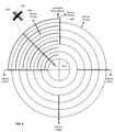
- FIG. 3is an illustration of a circular sensor array for a percussion device.
- FIGS. 4A and 4Billustrate examples of sensor circuitry for a percussion device.
- FIG. 5illustrates EMI shielding for a percussion device.
- FIG. 6is an illustration of a portion of circular sensor array for a percussion device.
- FIG. 7includes two graphs illustrating detection of hit events on a percussion device.
- FIG. 8is a flowchart illustrating hit event detection for a percussion device.
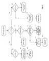
- FIG. 9is a flowchart illustrating hit event processing for a percussion device.
- Piezoresistive materialsinclude any of a class of materials that exhibit a change in electrical resistance in response to mechanical force (e.g., pressure, impact, distortion, etc.) applied to the material.
- One class of devices described hereinincludes conductive traces formed directly on or otherwise integrated with a dielectric substrate with piezoresistive material that is adjacent and/or tightly integrated with the dielectric substrate and in contact with at least some of the traces on the dielectric.
- Another class of devices described hereinincludes conductive traces formed directly on or otherwise integrated with a substrate of piezoresistive material, e.g., a piezoresistive fabric. When force is applied to such either type of device, the resistance between traces connected by the piezoresistive material changes in a time-varying manner that is representative of the applied force.
- a signal representative of the magnitude of the applied forceis generated based on the change in resistance.
- This signalis captured via the conductive traces (e.g., as a voltage or a current), digitized (e.g., via an analog-to-digital converter), processed (e.g., by an associated processor, controller, or suitable circuitry), and mapped (e.g., by the associated processor, controller, or circuitry, or a separate control system) to a control function that may be used in conjunction with the control and/or operation of virtually any type of process, device, or system.
- control functionsinclude generation of audio representations of percussion instruments.
- the piezoresistive material with which the traces are in contact or on which the traces are formedmay be any of a variety of woven and non-woven fabrics having piezoresistive properties. Implementations are also contemplated in which the piezoresistive material may be any of a variety of flexible, stretchable, or otherwise deformable materials (e.g., rubber, or a stretchable fabric such as spandex or open mesh fabrics) having piezoresistive properties.
- the conductive tracesmay be formed on the dielectric substrate or the piezoresistive material using any of a variety of conductive inks or paints. More generally, implementations are contemplated in which the conductive traces are formed using any conductive material that may be formed on either type of substrate. It should be understood with reference to the foregoing that, while specific implementations are described with reference to specific materials and techniques, the scope of this disclosure is not so limited.
- conductive tracescan be printed or formed on one or both sides of a substrate.
- two-sided implementationsmay require some mechanism for connecting conductive traces on one side of the substrate to those on the other side.
- Some implementationsuse vias through which conductive ink or paint is flowed to establish the connections.
- a wide range of conductive elementsmay be inserted to make connections through the substrate including, for example, pre-formed conductive vias, rivets, staples, wire, conductive thread, etc.
- Both single and double-sided implementationsmay also use insulating materials formed over or under conductive traces. This allows for the stacking or layering of conductive traces and signal lines, e.g., to allow the routing of signal line to isolated structures in a manner analogous to the different layers of a printed circuit board.
- Routing of signals on and off the substratemay be achieved in a variety of ways.
- elastomeric connectorse.g., ZEBRA® connectors
- ZEBRA® connectorswhich alternate conductive and non-conductive rubber at a density typically an order of magnitude greater than the width of the conductive traces to which they connect (e.g., at the edge of the substrate).
- a circuit board or a bundle of conductorsmay be riveted or otherwise secured to the substrate. The use of rivets may also provide mechanical reinforcement to the connection.
- matching conductive traces or pads on the substrate and a circuit boardcan be secured to each other using, for example, a layer of conductive adhesive (e.g., a conductive epoxy such as Masterbond EP79 from Masterbond, Inc. of Hackensack, N.J.) applied to one or both of the surfaces which are then mated to each other.
- a layer of conductive adhesivee.g., a conductive epoxy such as Masterbond EP79 from Masterbond, Inc. of Hackensack, N.J.
- the conductive traces or padscan also be held together with additional mechanical elements such as sonic welds or rivets. If conductive rivets are used to make the electrical connections to the conductive traces of the substrate, the conductive adhesive may not be required.
- Conductive threadsmay also be used to connect the conductive traces of the substrate to an external assembly.
- the piezoresistive materialis a pressure sensitive fabric manufactured by Eeonyx, Inc., of Pinole, Calif.
- the fabricincludes conductive particles that are polymerized to keep them suspended in the fabric.
- the base material(which may be, for example, a polyester felt) is selected for uniformity in density and thickness as this promotes greater uniformity in conductivity of the finished piezoresistive fabric. That is, the mechanical uniformity of the base material results in a more even distribution of conductive particles when the slurry containing the conductive particles is introduced.
- the fabricmay be woven.
- the fabricmay be non-woven such as, for example, a calendared fabric, e.g., fibers bonded together by chemical, mechanical, heat, or solvent treatment.
- calendared materialmay present a smooth outer surface which promotes more accurate screening of conductive inks.
- the conductive particles in the fabricmay be any of a wide variety of materials including, for example, silver, copper, gold, aluminum, carbon, etc. Some implementations may employ carbon graphene particles. Such materials may be fabricated using techniques described in U.S. Pat. No. 7,468,332 for Electroconductive Woven and Non-Woven Fabric issued on Dec. 23, 2008, the entire disclosure of which is incorporated herein by reference for all purposes. However, it should again be noted that any of a wide variety of materials that exhibit a change in resistance or conductivity when force is applied to the material may be suitable for implementation of sensors as described herein.
- conductive traces having varying levels of conductivityare formed on a dielectric substrate or piezoresistive material using conductive silicone-based inks manufactured by, for example, E.I. du Pont de Nemours and Company (DuPont) of Wilmington, Del., and/or Creative Materials of Ayer, Mass.
- conductive silicone-based inksmanufactured by, for example, E.I. du Pont de Nemours and Company (DuPont) of Wilmington, Del., and/or Creative Materials of Ayer, Mass.
- An example of a conductive ink suitable for implementing highly conductive traces for use with various implementationsis product number 125-19 from Creative Materials, a flexible, high temperature, electrically conductive ink.
- Examples of conductive inks for implementing lower conductivity traces for use with various implementationsare product numbers 7102 and 7105 from DuPont, both carbon conductive compositions.
- dielectric materials suitable for implementing insulators for use with various implementationsare product numbers 5018 and 5036 from DuPont, a UV curable dielectric and an encapsulant, respectively.
- These inksare flexible and durable. The degree of conductivity for different traces and applications may be controlled by the amount or concentration of conductive particles (e.g., silver, copper, aluminum, carbon, etc.) suspended in the silicone.
- conductive particlese.g., silver, copper, aluminum, carbon, etc.
- the substrate on which the inks are printedare non-stretchable allowing for the use of less expensive inks that are low in flexibility and/or stretchability.
- Another class of implementationsuses conductive paints (e.g., carbon particles mixed with paint) such as those that are commonly used for EMI shielding and ESD protection.
- FIG. 1An example of a percussion device 100 is shown in FIG. 1 .
- FIG. 2An exploded view of percussion device 100 is provided in FIG. 2 .
- the percussion devicehas four quadrants. Each quadrant is configured to detect and report hit events, including initial hit velocity (useful in forming a MIDI note). Each quadrant is also configured to detect and report a continuous range of force and a location (e.g., radial distance) of hit events on the top surface of percussion device 100 .
- the quadrants of the percussion deviceare formed by an array of conductive traces (e.g., screen printed conductive ink or paint) formed directly on or otherwise integrated with a dielectric substrate (e.g., a substrate 202 of polyethylene terephthalate or PET as shown in FIG. 2 ).
- a dielectric substratee.g., a substrate 202 of polyethylene terephthalate or PET as shown in FIG. 2 .
- An example of such an arrayis shown in a more detailed illustration of dielectric substrate 202 in FIG. 3 . Note that the orientation of dielectric 202 in FIG. 3 is opposite that shown in FIG. 2 in that the sensor traces in FIG. 2 are facing downward toward piezoresistive substrate 204 .
- Piezoresistive substrate 204(e.g., piezoresistive fabric) is in contact with at least some of the conductive traces on dielectric substrate 202 , i.e., the traces on the side of substrate 202 facing substrate 204 that aren't covered by an insulator. These substrates are secured between layers of silicone rubber 206 and 208 which protect the array and transmit impact energy to dielectric substrate 202 and piezoresistive substrate 204 .
- the underlying rubber layermay allow the piezoresistive fabric to distend, increasing the area of the fabric affected by the impact.
- a diffuser layere.g., 0.5 mm PET
- an impact evente.g., a hit of a drum stick
- the sensor arrayis energized and interrogated by analog circuitry and a processor located on a printed circuit board (PCB) 210 that is electrically bonded to the sensor array at notch 212 in dielectric substrate 202 .
- PCBprinted circuit board
- the conductive tracesare instead formed directly on or otherwise integrated with the piezoresistive substrate.
- PCB 210may be electrically bonded to the sensor array in the piezoresistive substrate in a similar manner.
- the conductive tracesare configured in a manner substantially similar to the array depicted in FIG. 3 .
- the structure of device 100is completed by securing top enclosure 214 to bottom enclosure 216 using fasteners 218 .
- Rubber foot 220is secured to bottom enclosure 216 with an adhesive, e.g., PSA 222 .
- FIGS. 4A and 4Bare simplified diagrams of sensor circuitry that may be provided, for example, on PCB 210 or another connected assembly for use with implementations described herein.
- sensor circuitrycould be connected to the conductive traces on dielectric substrate 202 (as represented by sensor array 401 ).
- a resulting signal(e.g., captured via the corresponding traces) is received (via reference amp 402 ), multiplexed (via multiplexer 403 ), and digitized (via A-to-D converter 404 ) and may be processed locally (e.g., by processor 406 ) and/or transmitted to a connected system or device (e.g., personal computer 409 ) via a wired connection (e.g., USB connector 411 ) or a wireless connection (e.g., a Bluetooth transceiver (not shown), etc.).
- a connected system or devicee.g., personal computer 409
- a wired connectione.g., USB connector 411
- a wireless connectione.g., a Bluetooth transceiver (not shown), etc.
- the sensors of sensor array 401may be selectively energized by the sensor circuitry (e.g., under the control of a GPIO (General Purpose Input Output) pin of processor 406 ).
- Processor 406may communicate with a remote system via a wired or wireless interface. Power may be provided to the sensor circuitry using any of a variety of mechanisms including one or more batteries.
- the sensor circuitry shown in FIG. 4Ais merely an example. A much wider range of sensor circuitry components, configurations, and functionalities are contemplated than depicted.
- processor 406may be included in the C8051F380-GM controller (provided by Silicon Labs of Austin, Tex.).
- Memory 407(which may or may not be included in processor 406 ) includes non-transitory computer-readable storage media that may be any of a wide variety of types of volatile and non-volatile storage media, and may include computer readable instructions, data structures, program modules, logic, firmware, and/or other data that implement or support the functionalities described herein.
- the PWM signal from processor 406is used for generation of a voltage for Vref that is between 0V and Vdd (the supply voltage of the controller) by varying the duty cycle of the PWM signal.
- the low-pass filterrejects the high carrier frequency and harmonics of the PWM signal, resulting in a substantially constant voltage for Vref that is proportional to duty cycle.
- Vrefis also provided to ADC 404 to allow for higher resolution readings of sensor output signals (e.g., in millivolts/count).
- An ADC countis equal (in mV) to positive Vref minus negative Vref divided by ADC range.
- positive Vrefis the filtered PWM signal
- negative Vrefis ground
- the ADC rangeis 1024 counts (10-bit resolution).
- the output of the amplifierswill never rise above Vref, only drop below it. This enables zooming in on the voltage range from Vref to ground without the input to the ADC rising above Vref, and beyond the ADC's operating range.
- the ADC step size in mV/countcan be decreased.
- the operation of the sensor array of the percussion devicemay be understood with reference to the simplified circuit diagram of FIG. 4B in which a programmable voltage is applied (e.g., by processor 406 ) across a piezoresistive fabric sensor f equal to (Vin ⁇ Vref).
- the current that flows through the fabric sensoris converted to a digital value (e.g., by ADC 404 ) and captured by the processor.
- the processoralternately drives 4 different conductive traces and samples 6 different analog channels, thereby addressing 24 sensor regions or locations. These sensor locations are each sampled over one thousand times per second in order to capture information about the percussionist's input and convert that into a standard MIDI over USB output.
- calibrated sensor datamay be stored (e.g., in memory 407 of processor 406 ) representing the response of each of the sensors. Such data may be used for ensuring consistency in the way the sensor outputs are processed and/or used to represent applied forces.
- the output of each sensore.g., as captured by ADC 404
- ADC 404the output of each sensor
- a set of data points for each sensoris captured (e.g., in a table in memory 407 ) associating ADC values with corresponding forces (e.g., weights in grams or kilograms).
- the data set for each sensormay capture a force value (or an offset value) for every possible value of the ADC output. Alternatively, fewer data points may be captured and the sensor circuitry may use interpolation to derive force values for ADC outputs not represented in the data set.
- shielding from electromagnetic interferenceis provided to prevent stray fields from affecting performance.
- stray fieldsmight be due, for example, to power grid 60-cycle hum, nearby wireless devices, capacitive coupling between the user's hands and the printed traces, etc.
- the EMI shieldcould be provided in a number of ways.
- conductive painte.g., nickel paint
- the shieldingmight be combined with the diffuser layer discussed above (e.g., with the conductive paint on the other side of the diffuser from the fabric).
- a conductive meshis provided on the opposite side of the dielectric substrate from the sensor traces.
- crosshatched conductive mesh 502may be screen printed or otherwise deposited on the top side of dielectric substrate 202 .
- the crosshatched meshmay be electrically connected to ground pads on PCB 210 and/or ground pads on the other side of dielectric substrate 202 , e.g., using conductive vias (not shown).
- Each quadrant of the percussion devicecorresponds to one of the four lines being driven by the processor.
- the configuration of the conductive traces of each quadrantmay be understood with reference to FIG. 6 which shows only some of the traces of dielectric substrate 202 for clarity.
- the solid traces in the upper left hand quadrantare all electrically connected to each other (by radial trace 602 ) and are the traces by which the quadrant is energized by a drive signal from the processor.
- Each of the circular traces(dashed lines) represents one of the six independent channels by which the sensors of each quadrant are sampled, i.e., hit events on the quadrant are represented in the signals on these sense traces transmitted as respective sensor outputs to the processor on the PCB (not shown).
- each circular sense trace that coincides with a particular quadrantforms a sensor with the adjacent drive traces in that quadrant.
- the location associated with each such sensor in a quadrantis the radial distance of the corresponding portion of the sense trace relative to the center of the array.
- the curved drive traces in each quadrantare discontinuous with the drive traces of the other quadrants, ending at the edges of the quadrant while the circular sense traces are continuous through all four quadrants.
- Thisis enabled by the use of an insulator 604 over radial trace 602 that allows the sense traces (e.g., sense trace 606 ) to cross the radial traces in each of the quadrants as shown in the magnified view. Insulator 604 also insulates the radial trace 602 from the piezoresistive substrate. Similar insulators are used in conjunction with the other radial drive traces (not shown) and the radial sense traces by which the sensor outputs are received.
- the processorsequentially drives the drive traces and sequentially samples the sense traces to generate a hit event data set.
- the generation of this data setis done repeatedly.
- the hit event data setincludes a value for each of the 24 combinations of drive traces and sense traces.
- the sequence used to generate the data setmay vary for different implementations. For example, the sequence can be organized by sense trace or by drive trace.
- sequential drive and samplingallows for detection of the location of hit events within a quadrant in terms of the radial distance from the center or edge of the device.
- hit detectionis performed by comparing ADC readings to an offset value stored for the corresponding sensor (e.g., in memory 407 ). As discussed above, this offset is unique to each sensor due to variations in resistance within the piezo-resistive material.
- the offset magnitudeis arrived at using an Infinite Impulse Response (IIR) filter. New readings are added to the current offset multiplied by a feedforward coefficient, and then this sum is divided by a feedback coefficient, equal to the feedforward coefficient plus one. This calculation is illustrated below:
- IIRInfinite Impulse Response
- offset 2( b * offset 1 ) + raw 2 a
- offset 1is the previously calculated offset
- raw 2is the latest ADC reading
- ais the feedback coefficient
- bis the feedforward coefficient
- offset 2is the resulting newly calculated offset.
- the offset for each sensoris repeatedly recalculated and stored (e.g., in memory 407 ) to account for changes in noise or in the material's resistance due, for example, to environmental effects. In the event that a hit is not recorded this recalculated offset is saved.
- a hysteresis schemeis implemented for hit detection because simply reporting high ADC readings might result in false triggers due to individual noise spikes.
- the schemeemploys two thresholds: one for amplitude and one for duration.
- the amplitude thresholdrequires the ADC reading for a sensor to be equal to or greater than the offset value plus the threshold. If the magnitude of the ADC reading is great enough, this constitutes a peak and increments a counter that keeps track of the number of adjacent peaks.
- All sensorsare initialized to the ‘IDLE’ state upon startup ( 802 ).
- a sensor's ADC reading 702peaks above the on amplitude threshold 704 ( 804 )
- a counter for that sensoris incremented ( 806 ), e.g., as represented by peaked state 706 .
- this count of contiguous samples above the on amplitude thresholdmeets the on length threshold ( 808 ), e.g., as with peak 710
- the state 708 of the sensorwill advance to the ‘HIT’ state of the state machine ( 810 ), e.g., 712 .
- This sensorwill be marked as hit using a Boolean flag for later use in the ‘hitProcess’ function. If the sample count does not meet the on length threshold, e.g., as with peak 714 , the state of the sensor remains ‘IDLE.’
- a sensor in the ‘HIT’ state ( 812 )drops below the off amplitude threshold ( 814 ), e.g., at 716 , another counter will increment ( 816 ). If this count of contiguous samples below the off amplitude threshold meets the off length threshold ( 818 ), the sensor will return to the ‘IDLE’ state of the state machine ( 820 ). The sensor hit flag will be cleared in this event.
- the calculation of the quadrant's centroid for radius interpolationoccurs within the ‘hitDetect’ function. If a sensor is hit ( 830 ), its amplitude is retained ( 832 ) (if it is the greatest of the active sensors in the quadrant), and its radius multiplied by its pressure is added to an accumulator, containing these products for all active sensors within the quadrant ( 834 ). After all terms have been accumulated, the sum of products is divided by the sum of pressures to return the interpolated radius ( 836 ) and the quadrant is marked as registering a hit ( 838 ). The greatest pressure within the quadrant (i.e., the greatest amplitude) is stored as that quadrant's pressure ( 840 ).
- the interpolated location of the hitis calculated from the velocities of all hit sensors within the quadrant of interest for which hits are reported.
- the interpolated location of the hitmay be calculated using the following weighted average equation:
- radiusrefers to the distance between the sensor and the center of the sensor array (i.e., the radial distance from the center of the array to the particular circular sense line with which the hit is correlated)
- velocityrefers to the magnitude of the ADC reading for the hit above the offset
- a, b, and crefer to the sensors for which hits were reported that are used in calculating the location
- xrefers to the interpolated location.
- the velocity of the impactis taken to be the highest of the velocities.
- the velocity of impactmay be calculated by a simple average of the velocities.
- the flowchart of FIG. 9illustrates the output of modlines via MIDI messages using the quadrant pressure and radius values calculated within the ‘hitDetect’ function.
- a “modline”is a set of parameters specified by a user (e.g., in a device configuration user interface) that transform the sensor outputs to desired behaviors.
- a modlinemight select an input, apply transformations such as gain (e.g., a multiplier) and offset (e.g., add to or subtract from) to that input, and output the transformed value in a specified message format (e.g., ‘MIDI note on’ or ‘MIDI pitch bend.)
- a modlinemight also impose minimum and maximum range limits as well as apply transformations (e.g., linear, log, exp) that change the shape of the response.
- the usercould specify that pressure on a sensor only begins to register at 50% of the sensor's range by specifying an offset of minus 50%. By then specifying a gain factor of 2 ⁇ , the effective range of the sensor is shifted, e.g., to a more desirable gesture response.
- all quadrantsare initialized to the ‘IDLE’ state ( 902 ). If the quadrant is designated as hit by a flag ( 904 ), it will advance to the ‘HIT_START’ state ( 908 ), with the current pressure and radius values being retained as the initial pressure and initial radius values, respectively ( 906 ). If the quadrant is not hit, it will remain in the ‘IDLE’ state.
- the quadrantIn the ‘HIT_START’ state ( 910 ), if the quadrant is still hit ( 911 ), and the current pressure value is greater than the previous initial pressure value ( 912 ), the new pressure and radius values will be retained as the initial values ( 914 ). If the current pressure is less than or equal to the previous initial value, the quadrant will send out all active modlines using the initial pressure and radius values ( 918 ) and advance to the ‘HIT_STREAM’ state ( 916 ).
Landscapes
- Physics & Mathematics (AREA)
- Engineering & Computer Science (AREA)
- Acoustics & Sound (AREA)
- Multimedia (AREA)
- General Physics & Mathematics (AREA)
- Electrophonic Musical Instruments (AREA)
- Measurement Of Mechanical Vibrations Or Ultrasonic Waves (AREA)
- Shielding Devices Or Components To Electric Or Magnetic Fields (AREA)
Abstract
Description
where offset1is the previously calculated offset, raw2is the latest ADC reading, a is the feedback coefficient, b is the feedforward coefficient, and offset2is the resulting newly calculated offset. The offset for each sensor is repeatedly recalculated and stored (e.g., in memory407) to account for changes in noise or in the material's resistance due, for example, to environmental effects. In the event that a hit is not recorded this recalculated offset is saved.
where radius refers to the distance between the sensor and the center of the sensor array (i.e., the radial distance from the center of the array to the particular circular sense line with which the hit is correlated), velocity refers to the magnitude of the ADC reading for the hit above the offset, a, b, and c refer to the sensors for which hits were reported that are used in calculating the location, and x refers to the interpolated location. According to some implementations, the velocity of the impact is taken to be the highest of the velocities. According to other implementations, the velocity of impact may be calculated by a simple average of the velocities.
Claims (58)
Priority Applications (4)
| Application Number | Priority Date | Filing Date | Title |
|---|---|---|---|
| US15/287,520US9721553B2 (en) | 2015-10-14 | 2016-10-06 | Sensor-based percussion device |
| DE112016004743.6TDE112016004743B4 (en) | 2015-10-14 | 2016-10-07 | Sensor-based percussion device |
| PCT/US2016/055997WO2017066096A1 (en) | 2015-10-14 | 2016-10-07 | Sensor-based percussion device |
| JP2018515520AJP6763113B2 (en) | 2015-10-14 | 2016-10-07 | Sensor-based percussion device |
Applications Claiming Priority (2)
| Application Number | Priority Date | Filing Date | Title |
|---|---|---|---|
| US201562241615P | 2015-10-14 | 2015-10-14 | |
| US15/287,520US9721553B2 (en) | 2015-10-14 | 2016-10-06 | Sensor-based percussion device |
Publications (2)
| Publication Number | Publication Date |
|---|---|
| US20170110103A1 US20170110103A1 (en) | 2017-04-20 |
| US9721553B2true US9721553B2 (en) | 2017-08-01 |
Family
ID=58517801
Family Applications (1)
| Application Number | Title | Priority Date | Filing Date |
|---|---|---|---|
| US15/287,520ActiveUS9721553B2 (en) | 2015-10-14 | 2016-10-06 | Sensor-based percussion device |
Country Status (4)
| Country | Link |
|---|---|
| US (1) | US9721553B2 (en) |
| JP (1) | JP6763113B2 (en) |
| DE (1) | DE112016004743B4 (en) |
| WO (1) | WO2017066096A1 (en) |
Cited By (12)
| Publication number | Priority date | Publication date | Assignee | Title |
|---|---|---|---|---|
| US9863823B2 (en) | 2015-02-27 | 2018-01-09 | Bebop Sensors, Inc. | Sensor systems integrated with footwear |
| US20180025711A1 (en)* | 2015-02-06 | 2018-01-25 | Kuljit BHAMRA | Percussion instrument |
| US9965076B2 (en) | 2014-05-15 | 2018-05-08 | Bebop Sensors, Inc. | Piezoresistive sensors and applications |
| US10082381B2 (en) | 2015-04-30 | 2018-09-25 | Bebop Sensors, Inc. | Sensor systems integrated with vehicle tires |
| US10114493B2 (en) | 2012-03-14 | 2018-10-30 | Bebop Sensors, Inc. | Multi-touch pad controller |
| US10268315B2 (en) | 2014-05-15 | 2019-04-23 | Bebop Sensors, Inc. | Two-dimensional sensor arrays |
| US10282011B2 (en) | 2014-05-15 | 2019-05-07 | Bebop Sensors, Inc. | Flexible sensors and applications |
| US10288507B2 (en) | 2009-10-16 | 2019-05-14 | Bebop Sensors, Inc. | Piezoresistive sensors and sensor arrays |
| US10362989B2 (en) | 2014-06-09 | 2019-07-30 | Bebop Sensors, Inc. | Sensor system integrated with a glove |
| US10654486B2 (en) | 2015-06-25 | 2020-05-19 | Bebop Sensors, Inc. | Sensor systems integrated with steering wheels |
| US10884496B2 (en) | 2018-07-05 | 2021-01-05 | Bebop Sensors, Inc. | One-size-fits-all data glove |
| US11480481B2 (en) | 2019-03-13 | 2022-10-25 | Bebop Sensors, Inc. | Alignment mechanisms sensor systems employing piezoresistive materials |
Families Citing this family (2)
| Publication number | Priority date | Publication date | Assignee | Title |
|---|---|---|---|---|
| CN107402099B (en)* | 2017-09-12 | 2024-04-23 | 沈阳振科仪表有限公司 | Impact transmitter |
| FR3083361B1 (en)* | 2018-06-28 | 2021-10-15 | Drumistic | REMOVABLE ELECTRONIC EMULATION DEVICE SUITABLE TO BE FIXED ON AN ACOUSTIC BATTERY |
Citations (134)
| Publication number | Priority date | Publication date | Assignee | Title |
|---|---|---|---|---|
| US4294014A (en) | 1979-03-27 | 1981-10-13 | Bidegain S.A. | Apparatus for determining the shoe size corresponding to a foot |
| US4438291A (en) | 1982-03-08 | 1984-03-20 | General Electric Company | Screen-printable thermocouples |
| EP0014022B1 (en) | 1979-01-25 | 1984-11-14 | Technisch Advies- en Handelsbureau Hoogstraat C.V. | Foot-size measuring apparatus |
| US4852443A (en)* | 1986-03-24 | 1989-08-01 | Key Concepts, Inc. | Capacitive pressure-sensing method and apparatus |
| NL8900820A (en) | 1989-04-04 | 1990-11-01 | Hoogstraat Med Tech | Automatic shoe size measuring appts. - measures both inside and outside dimensions using sensors supplying microprocessor |
| US5033291A (en) | 1989-12-11 | 1991-07-23 | Tekscan, Inc. | Flexible tactile sensor for measuring foot pressure distributions and for gaskets |
| US5128880A (en) | 1990-05-11 | 1992-07-07 | Foot Image Technology, Inc. | Foot measurement and footwear sizing system |
| US5131306A (en) | 1989-01-19 | 1992-07-21 | Yamaha Corporation | Automatic music playing piano |
| US5237520A (en) | 1990-05-11 | 1993-08-17 | Foot Image Technology, Inc. | Foot measurement and footwear sizing system |
| US5288938A (en) | 1990-12-05 | 1994-02-22 | Yamaha Corporation | Method and apparatus for controlling electronic tone generation in accordance with a detected type of performance gesture |
| US5429092A (en) | 1993-02-25 | 1995-07-04 | Mitsubishi Denki Kabushiki Kaisha | Throttle control system |
| JPH08194481A (en) | 1995-01-13 | 1996-07-30 | Roland Corp | Editing method with foot controller |
| US5571973A (en) | 1994-06-06 | 1996-11-05 | Taylot; Geoffrey L. | Multi-directional piezoresistive shear and normal force sensors for hospital mattresses and seat cushions |
| US5578766A (en) | 1994-04-05 | 1996-11-26 | Nec Corporation | Force detector/indicator |
| US5659395A (en) | 1992-06-23 | 1997-08-19 | Footmark, Inc. | Method and apparatus for analyzing feet |
| US5695859A (en) | 1995-04-27 | 1997-12-09 | Burgess; Lester E. | Pressure activated switching device |
| US5729905A (en) | 1995-09-11 | 1998-03-24 | Dwayne L. Mason | Foot measuring apparatus and circuitry to eliminate multiplexes and demultiplexers |
| US5822223A (en) | 1997-08-05 | 1998-10-13 | Genovation Inc. | Electronic foot measuring apparatus |
| US5866829A (en) | 1996-12-20 | 1999-02-02 | Pecoraro; Thomas | Pedal rack |
| US5878359A (en) | 1995-06-09 | 1999-03-02 | Nipponsenso Co., Ltd. | Vehicular control device provided with an accelerator detecting device which detects the operation of an accelerator device |
| WO1999020179A1 (en) | 1997-10-23 | 1999-04-29 | Mason, Dwayne, L. | Solid state digital electronic shoe sizer |
| US5943044A (en) | 1996-08-05 | 1999-08-24 | Interlink Electronics | Force sensing semiconductive touchpad |
| US5989700A (en) | 1996-01-05 | 1999-11-23 | Tekscan Incorporated | Pressure sensitive ink means, and methods of use |
| JP2000267664A (en) | 1999-03-16 | 2000-09-29 | Yamaha Corp | Playing data processing system |
| US6155120A (en) | 1995-11-14 | 2000-12-05 | Taylor; Geoffrey L. | Piezoresistive foot pressure measurement method and apparatus |
| US6215055B1 (en) | 1997-08-06 | 2001-04-10 | Darren Saravis | Foot pedal boards for musical instruments |
| US6304840B1 (en) | 1998-06-30 | 2001-10-16 | U.S. Philips Corporation | Fingerless glove for interacting with data processing system |
| US6331893B1 (en) | 1992-06-23 | 2001-12-18 | Footmark, Inc. | Foot analyzer |
| US6360615B1 (en) | 2000-06-06 | 2002-03-26 | Technoskin, Llc | Wearable effect-emitting strain gauge device |
| US20020078757A1 (en) | 2000-06-30 | 2002-06-27 | Jacqueline Hines | Surface-acoustic-wave pressure sensor and associated methods |
| US6486776B1 (en) | 1998-04-14 | 2002-11-26 | The Goodyear Tire & Rubber Company | RF transponder and method of measuring parameters associated with a monitored object |
| US20040031180A1 (en) | 2002-06-17 | 2004-02-19 | Dentcho Ivanov | Sensor array for unauthorized user prevention device |
| US20040093746A1 (en) | 2000-08-18 | 2004-05-20 | Salvatore Varsallona | System for measuring the correct size of shoes |
| US20040183648A1 (en) | 2003-03-21 | 2004-09-23 | Weber Thomas E. | Strain sensors and housings and circuit boards with integrated strain sensors |
| US20040189145A1 (en) | 1999-01-28 | 2004-09-30 | Baruch Pletner | Method and device for vibration control |
| US6815602B2 (en) | 2002-09-30 | 2004-11-09 | Vince De Franco | Electronic percussion instrument with impact position-dependent variable resistive switch |
| US6822635B2 (en) | 2000-01-19 | 2004-11-23 | Immersion Corporation | Haptic interface for laptop computers and other portable devices |
| US6829942B2 (en) | 2002-06-27 | 2004-12-14 | Denso Corporation | Pressure sensor |
| US20050109095A1 (en) | 2003-11-20 | 2005-05-26 | Sinnett Jay C. | Saw transducer interface to pressure sensing diaphragm |
| US6964205B2 (en) | 2003-12-30 | 2005-11-15 | Tekscan Incorporated | Sensor with plurality of sensor elements arranged with respect to a substrate |
| US7157640B2 (en) | 2003-06-17 | 2007-01-02 | Baggs Lloyd R | Undersaddle pickup for stringed musical instrument |
| KR20070008500A (en) | 2006-12-29 | 2007-01-17 | 이학범 | Ultrasonic Foot Size Automatic Measuring System |
| WO2007024875A2 (en) | 2005-08-22 | 2007-03-01 | Jay White | Method and system for providing customized footwear to a consumer |
| US20070129776A1 (en) | 2005-10-20 | 2007-06-07 | Light Sciences Llc | External wearable light therapy treatment systems |
| US20070188179A1 (en) | 2006-02-10 | 2007-08-16 | Deangelis Alfred R | Printed capacitive sensor |
| US20070202765A1 (en) | 2004-03-31 | 2007-08-30 | Koninklijke Philips Electronics, N.V. | Textile form touch sensor |
| US20070234888A1 (en) | 2005-10-03 | 2007-10-11 | Audiobrax Industria E Comercio De Produtos Eletronicos S/A | Rhythmic device for the production, playing, accompaniment and evaluation of sounds |
| CN200980381Y (en) | 2006-08-31 | 2007-11-28 | 陈波 | Device for selecting shoe size according with measured foot size |
| US7332670B2 (en) | 2004-07-27 | 2008-02-19 | Yamaha Corporation | Automatic player exactly bringing pedal to half point, musical instrument equipped therewith and method used therein |
| JP2008515008A (en) | 2004-10-01 | 2008-05-08 | オーディオブラックス インドゥストリア エ コメルシオ デ プロドゥトス エレトロニコス ソシエダッド アノニマ | Rhythm device for sound generation, performance, accompaniment and evaluation |
| US20080158145A1 (en) | 2007-01-03 | 2008-07-03 | Apple Computer, Inc. | Multi-touch input discrimination |
| US7409256B2 (en) | 2005-12-16 | 2008-08-05 | Industrial Technology Research Institute | Footwear measurement and footwear manufacture systems and methods |
| US20080254824A1 (en) | 2005-02-02 | 2008-10-16 | Aurelio Rotolo Moraes | Mobile Communication Device with Musical Instrument Functions |
| KR100865148B1 (en) | 2006-12-14 | 2008-10-24 | 이학범 | Foot size automatic measuring device |
| US7493230B2 (en) | 2006-06-06 | 2009-02-17 | Aetrex Worldwide, Inc. | Method and apparatus for customizing insoles for footwear |
| US20090049980A1 (en) | 2003-07-25 | 2009-02-26 | Ravi Sharma | Inverted keyboard instrument and method of playing the same |
| US7536794B2 (en) | 2005-05-20 | 2009-05-26 | Bivab, Llc | Foot measurement, alignment and evaluation device |
| US20090237374A1 (en) | 2008-03-20 | 2009-09-24 | Motorola, Inc. | Transparent pressure sensor and method for using |
| US7608776B2 (en) | 2003-12-15 | 2009-10-27 | Ludwig Lester F | Modular structures facilitating field-customized floor controllers |
| US20090272197A1 (en) | 2006-07-06 | 2009-11-05 | Miguel Ridao Granado | Torsion and/or Tension And/or Pressure Textile Sensor |
| US20090301190A1 (en) | 2008-06-09 | 2009-12-10 | Rochester Gauges, Inc. | Capacitive sensor assembly for determining relative position |
| WO2009155891A1 (en) | 2008-06-25 | 2009-12-30 | Conti Temic Microelectronic Gmbh | Circuit and method for controlling a trimorphemic piezoelectric actuator |
| US7719007B2 (en) | 2008-04-30 | 2010-05-18 | Milliken & Company | Flexible electroluminescent capacitive sensor |
| US20100134327A1 (en) | 2008-11-28 | 2010-06-03 | Dinh Vincent Vinh | Wireless haptic glove for language and information transference |
| US20100149108A1 (en) | 2008-12-11 | 2010-06-17 | Steve Porter Hotelling | Single layer touch panel with segmented drive and sense electrodes |
| US7754956B2 (en) | 2007-12-12 | 2010-07-13 | Force Ten International Llc | Programmable system to integrate generated signals with signals from a musical instrument |
| US20100179724A1 (en) | 2007-06-20 | 2010-07-15 | David Alan Weston | Autolocation of all tire id's on a multi-axle vehicle |
| US7780541B2 (en) | 2005-04-20 | 2010-08-24 | David Bauer | Golf training glove |
| US20100274447A1 (en) | 2008-05-05 | 2010-10-28 | Stumpf John F | Transducer matrix film |
| US20100286951A1 (en) | 2008-01-07 | 2010-11-11 | Aetrex Worldwide Inc. | Foot measuring device |
| US20100292945A1 (en) | 2009-05-13 | 2010-11-18 | Joseph Kurth Reynolds | Capacitive sensor device |
| US20100315337A1 (en) | 2009-06-16 | 2010-12-16 | Bran Ferren | Optical capacitive thumb control with pressure sensor |
| US20110088536A1 (en) | 2009-10-16 | 2011-04-21 | Kesumo Llc | Foot-operated controller |
| US20110088535A1 (en) | 2008-03-11 | 2011-04-21 | Misa Digital Pty Ltd. | digital instrument |
| US20110141052A1 (en) | 2009-12-10 | 2011-06-16 | Jeffrey Traer Bernstein | Touch pad with force sensors and actuator feedback |
| US7984544B2 (en) | 2005-06-16 | 2011-07-26 | Ilya D. Rosenberg | Method for manufacturing long force sensors using screen printing technology |
| CN201920728U (en) | 2010-12-27 | 2011-08-10 | 北京汉林信通信息技术有限公司 | Automatic height, weight and foot length measuring device for people |
| US20110241850A1 (en) | 2010-03-31 | 2011-10-06 | Tk Holdings Inc. | Steering wheel sensors |
| US20110246028A1 (en) | 2010-04-02 | 2011-10-06 | Tk Holdings Inc. | Steering wheel with hand pressure sensing |
| US20110260994A1 (en) | 2010-03-19 | 2011-10-27 | Xavier Pierre-Emmanuel Saynac | Systems and methods for determining the location and pressure of a touchload applied to a touchpad |
| US20110271772A1 (en) | 2007-04-23 | 2011-11-10 | Sierra Scientific Instruments, Inc. | Suspended membrane pressure sensing array |
| US20120007831A1 (en) | 2009-10-09 | 2012-01-12 | Egalax_Empia Technology Inc. | Method and device for position detection |
| US20120026124A1 (en) | 2010-07-31 | 2012-02-02 | Motorola, Inc. | Touch screen rendering system and method of operation thereof |
| US8117922B2 (en) | 2006-09-21 | 2012-02-21 | Msd Consumer Care, Inc. | Footcare product dispensing kiosk |
| US20120055257A1 (en)* | 2010-09-08 | 2012-03-08 | Micropen Technologies Corporation | Pressure sensing or force generating device |
| US8161826B1 (en) | 2009-03-05 | 2012-04-24 | Stryker Corporation | Elastically stretchable fabric force sensor arrays and methods of making |
| CN102551728A (en) | 2010-12-27 | 2012-07-11 | 北京汉林信通信息技术有限公司 | Automatic measuring device for heights, body weights and foot lengths of persons |
| US20120198949A1 (en) | 2006-09-21 | 2012-08-09 | Msd Consumer Care, Inc. | Footcare product dispensing kiosk |
| CN202396601U (en) | 2011-12-21 | 2012-08-29 | 夏彬 | Body-measuring and size-selecting device |
| US8274485B2 (en) | 2008-09-30 | 2012-09-25 | Tpk Touch Solutions Inc. | Touch position detection method for touch control device |
| US20120283979A1 (en) | 2009-12-21 | 2012-11-08 | Koninklijke Philips Electronics N.V. | Sensor system |
| US20120296528A1 (en) | 2011-05-20 | 2012-11-22 | Matthias Marcus Wellhoefer | Haptic steering wheel, steering-wheel system and driver assistance system for a motor vehicle |
| US20120297885A1 (en)* | 2011-05-23 | 2012-11-29 | Universal Cement Corporation | Preloaded pressure sensor module |
| US20120323501A1 (en) | 2011-05-20 | 2012-12-20 | The Regents Of The University Of California | Fabric-based pressure sensor arrays and methods for data analysis |
| US20130009905A1 (en) | 2011-07-06 | 2013-01-10 | Sharp Kabushiki Kaisha | Dual-function transducer for a touch panel |
| US20130055482A1 (en) | 2011-09-02 | 2013-03-07 | Fiat Group Automobiles S.P.A. | Method for designing a protective glove to be used in performing a cycle of manual operations in an industrial production line, and glove designed by this method |
| US20130082970A1 (en) | 2010-06-11 | 2013-04-04 | 3M Innovative Properties Company | Positional touch sensor with force measurement |
| US20130085394A1 (en) | 2011-10-04 | 2013-04-04 | Sonivate Medical, Inc. | Glove with integrated sensor |
| US8448530B2 (en) | 2009-03-27 | 2013-05-28 | CSEM Centre Suisee d'Electronique et de Microtechnique SA-Recherche et Developpement | Roll-to-roll compatible pressure sensitive event sensing label |
| US20130192071A1 (en) | 2012-01-30 | 2013-08-01 | Heapsylon LLC | Sensors, interfaces and sensor systems for data collection and integrated remote monitoring of conditions at or near body surfaces |
| US20130211208A1 (en) | 2011-03-08 | 2013-08-15 | Vijay K. Varadan | Smart materials, dry textile sensors, and electronics integration in clothing, bed sheets, and pillow cases for neurological, cardiac and/or pulmonary monitoring |
| US20130239787A1 (en)* | 2012-03-14 | 2013-09-19 | Kesumo Llc | Multi-touch pad controller |
| CN203234132U (en) | 2013-05-12 | 2013-10-16 | 夏彬 | Foot length measuring device |
| US20130274985A1 (en) | 2012-04-16 | 2013-10-17 | GM Global Technology Operations LLC | System and method for vehicle lateral control |
| US20130275057A1 (en) | 2010-10-12 | 2013-10-17 | Tactonic Technologies, Llc | Sensor Having a Mesh Layer with Protrusions, and Method |
| US20130327560A1 (en) | 2011-02-24 | 2013-12-12 | Fujifilm Corporation | Electroconductive sheet and touch panel |
| EP2682724A1 (en) | 2012-07-04 | 2014-01-08 | Sensing Tex, S.L. | A large-area extensible pressure sensor for textiles surfaces |
| KR101362742B1 (en) | 2012-12-21 | 2014-02-13 | 현대오트론 주식회사 | A tire management system and a vehicle comprising the same |
| CN102406280B (en) | 2011-12-21 | 2014-03-19 | 夏彬 | Device for selecting size by body measurement |
| US20140090488A1 (en)* | 2012-09-29 | 2014-04-03 | Stryker Corporation | Flexible Piezocapacitive And Piezoresistive Force And Pressure Sensors |
| US20140125124A1 (en) | 2012-11-05 | 2014-05-08 | Nissan North America, Inc. | Vehicle horn control assembly |
| US20140130593A1 (en) | 2012-11-13 | 2014-05-15 | Industrial Technology Research Institute | Pressure measurement structure |
| US20140150573A1 (en) | 2011-01-13 | 2014-06-05 | Francis Cannard | Device for Measuring Pressure from a Flexible, Pliable, and/or Extensible Object Made from a Textile Material Comprising a Measurement Device |
| KR20140071693A (en) | 2012-12-04 | 2014-06-12 | 정홍기 | Method for measuring foot size using autofocus |
| US20140182170A1 (en) | 2012-12-19 | 2014-07-03 | New Balance Athletic Shoe, Inc. | Customized footwear, and systems and methods for designing and manufacturing same |
| US20140195023A1 (en) | 2011-08-09 | 2014-07-10 | Nederlandse Organisatie Voor Toegepast-Natuurweten Schappelijk Onderzoek Tno | Method and system for feedback on running style field and background of the invention |
| US20140215684A1 (en) | 2013-02-07 | 2014-08-07 | Timothy J. Hardy | Pressure Sensing Glove |
| US20140318699A1 (en) | 2012-09-11 | 2014-10-30 | Gianluigi LONGINOTTI-BUITONI | Methods of making garments having stretchable and conductive ink |
| US8925393B2 (en) | 2011-01-25 | 2015-01-06 | Francis Cannard | Device intended for measuring pressure from a flexible, foldable, and/or extendable object made of a textile material and comprising a measurement device |
| US8964205B2 (en) | 2012-03-26 | 2015-02-24 | SCREEN Holdings Co., Ltd. | Print control apparatus, inkjet printing apparatus, print control method, and recording medium with data compression/decompression |
| US20150084873A1 (en) | 2013-09-25 | 2015-03-26 | Lenovo (Singapore) Pte. Ltd. | Integrating multiple different touch based inputs |
| US20150086955A1 (en) | 2012-05-03 | 2015-03-26 | Lauren H. Poniatowski | Systems and methods for analyzing surgical techniques |
| WO2015175317A1 (en) | 2014-05-15 | 2015-11-19 | Bebop Sensors, Inc. | Piezoresistive sensors and applications |
| US20150331522A1 (en) | 2014-05-15 | 2015-11-19 | Kesumo Llc | Piezoresistive sensors and applications |
| US20150331512A1 (en) | 2014-05-15 | 2015-11-19 | Bebop Sensors, Inc. | Promoting sensor isolation and performance in flexible sensor arrays |
| US20150331533A1 (en) | 2014-05-15 | 2015-11-19 | Bebop Sensors, Inc. | Flexible sensors and applications |
| US20150331524A1 (en) | 2014-05-15 | 2015-11-19 | Bebop Sensors, Inc. | Two-dimensional sensor arrays |
| US20150370396A1 (en) | 2012-12-14 | 2015-12-24 | Apple Inc. | Force Sensing Based on Capacitance Changes |
| US20160054798A1 (en) | 2014-08-22 | 2016-02-25 | Sony Computer Entertainment Inc. | Glove Interface Object |
| US20160070347A1 (en) | 2014-06-09 | 2016-03-10 | Bebop Sensors, Inc. | Sensor system integrated with a glove |
| WO2016070078A1 (en) | 2014-10-30 | 2016-05-06 | Bebop Sensors, Inc. | Sensor system integrated with a glove |
| US20160252412A1 (en) | 2015-02-27 | 2016-09-01 | Bebop Sensors, Inc. | Sensor systems integrated with footwear |
| WO2016176307A1 (en) | 2015-04-30 | 2016-11-03 | Bebop Sensors, Inc. | Sensor systems integrated with vehicle tires |
| US20160375910A1 (en) | 2015-06-25 | 2016-12-29 | Bebop Sensors, Inc. | Sensor systems integrated with steering wheels |
Family Cites Families (7)
| Publication number | Priority date | Publication date | Assignee | Title |
|---|---|---|---|---|
| US7109068B2 (en)* | 2004-08-31 | 2006-09-19 | Micron Technology, Inc. | Through-substrate interconnect fabrication methods |
| US7468332B2 (en) | 2005-09-02 | 2008-12-23 | Jamshid Avloni | Electroconductive woven and non-woven fabric |
| US8378203B2 (en)* | 2010-07-27 | 2013-02-19 | Pure Imagination, LLC | Simulated percussion instrument |
| US8354581B2 (en)* | 2010-10-22 | 2013-01-15 | MIDItroniX, LLC | Hybrid drum |
| BE1019917A5 (en)* | 2011-03-15 | 2013-02-05 | Den Broeck Bram Van | DEVICE FOR MEASURING PHYSICAL CHARACTERISTICS OR CHANGES IN PHYSICAL CHARACTERISTICS IN A SHEET AND SHAPE ADAPTED FOR USE WITH SUCH DEVICE. |
| US8933315B2 (en)* | 2012-06-22 | 2015-01-13 | Aquarian Coatings Corp. | Impact responsive portable electronic drumhead |
| RU2533539C1 (en)* | 2013-05-27 | 2014-11-20 | Федеральное государственное бюджетное образовательное учреждение высшего профессионального образования "Тверской государственный университет" | Piezoelectric shock pick-up |
- 2016
- 2016-10-06USUS15/287,520patent/US9721553B2/enactiveActive
- 2016-10-07JPJP2018515520Apatent/JP6763113B2/ennot_activeExpired - Fee Related
- 2016-10-07WOPCT/US2016/055997patent/WO2017066096A1/ennot_activeCeased
- 2016-10-07DEDE112016004743.6Tpatent/DE112016004743B4/ennot_activeExpired - Fee Related
Patent Citations (168)
| Publication number | Priority date | Publication date | Assignee | Title |
|---|---|---|---|---|
| EP0014022B1 (en) | 1979-01-25 | 1984-11-14 | Technisch Advies- en Handelsbureau Hoogstraat C.V. | Foot-size measuring apparatus |
| US4294014A (en) | 1979-03-27 | 1981-10-13 | Bidegain S.A. | Apparatus for determining the shoe size corresponding to a foot |
| US4438291A (en) | 1982-03-08 | 1984-03-20 | General Electric Company | Screen-printable thermocouples |
| US4852443A (en)* | 1986-03-24 | 1989-08-01 | Key Concepts, Inc. | Capacitive pressure-sensing method and apparatus |
| US5131306A (en) | 1989-01-19 | 1992-07-21 | Yamaha Corporation | Automatic music playing piano |
| NL8900820A (en) | 1989-04-04 | 1990-11-01 | Hoogstraat Med Tech | Automatic shoe size measuring appts. - measures both inside and outside dimensions using sensors supplying microprocessor |
| US5033291A (en) | 1989-12-11 | 1991-07-23 | Tekscan, Inc. | Flexible tactile sensor for measuring foot pressure distributions and for gaskets |
| US5128880A (en) | 1990-05-11 | 1992-07-07 | Foot Image Technology, Inc. | Foot measurement and footwear sizing system |
| US5237520A (en) | 1990-05-11 | 1993-08-17 | Foot Image Technology, Inc. | Foot measurement and footwear sizing system |
| US5288938A (en) | 1990-12-05 | 1994-02-22 | Yamaha Corporation | Method and apparatus for controlling electronic tone generation in accordance with a detected type of performance gesture |
| US6331893B1 (en) | 1992-06-23 | 2001-12-18 | Footmark, Inc. | Foot analyzer |
| US5659395A (en) | 1992-06-23 | 1997-08-19 | Footmark, Inc. | Method and apparatus for analyzing feet |
| US5429092A (en) | 1993-02-25 | 1995-07-04 | Mitsubishi Denki Kabushiki Kaisha | Throttle control system |
| US5578766A (en) | 1994-04-05 | 1996-11-26 | Nec Corporation | Force detector/indicator |
| US5571973A (en) | 1994-06-06 | 1996-11-05 | Taylot; Geoffrey L. | Multi-directional piezoresistive shear and normal force sensors for hospital mattresses and seat cushions |
| JPH08194481A (en) | 1995-01-13 | 1996-07-30 | Roland Corp | Editing method with foot controller |
| US5695859A (en) | 1995-04-27 | 1997-12-09 | Burgess; Lester E. | Pressure activated switching device |
| US5878359A (en) | 1995-06-09 | 1999-03-02 | Nipponsenso Co., Ltd. | Vehicular control device provided with an accelerator detecting device which detects the operation of an accelerator device |
| US5729905A (en) | 1995-09-11 | 1998-03-24 | Dwayne L. Mason | Foot measuring apparatus and circuitry to eliminate multiplexes and demultiplexers |
| US6029358A (en) | 1995-09-11 | 2000-02-29 | Dwayne L. Mason | Solid state digital electronic shoe sizer |
| US6155120A (en) | 1995-11-14 | 2000-12-05 | Taylor; Geoffrey L. | Piezoresistive foot pressure measurement method and apparatus |
| US6216545B1 (en) | 1995-11-14 | 2001-04-17 | Geoffrey L. Taylor | Piezoresistive foot pressure measurement |
| US5989700A (en) | 1996-01-05 | 1999-11-23 | Tekscan Incorporated | Pressure sensitive ink means, and methods of use |
| US5943044A (en) | 1996-08-05 | 1999-08-24 | Interlink Electronics | Force sensing semiconductive touchpad |
| US5866829A (en) | 1996-12-20 | 1999-02-02 | Pecoraro; Thomas | Pedal rack |
| US5822223A (en) | 1997-08-05 | 1998-10-13 | Genovation Inc. | Electronic foot measuring apparatus |
| US6215055B1 (en) | 1997-08-06 | 2001-04-10 | Darren Saravis | Foot pedal boards for musical instruments |
| WO1999020179A1 (en) | 1997-10-23 | 1999-04-29 | Mason, Dwayne, L. | Solid state digital electronic shoe sizer |
| US6486776B1 (en) | 1998-04-14 | 2002-11-26 | The Goodyear Tire & Rubber Company | RF transponder and method of measuring parameters associated with a monitored object |
| US6304840B1 (en) | 1998-06-30 | 2001-10-16 | U.S. Philips Corporation | Fingerless glove for interacting with data processing system |
| US20040189145A1 (en) | 1999-01-28 | 2004-09-30 | Baruch Pletner | Method and device for vibration control |
| JP2000267664A (en) | 1999-03-16 | 2000-09-29 | Yamaha Corp | Playing data processing system |
| US6822635B2 (en) | 2000-01-19 | 2004-11-23 | Immersion Corporation | Haptic interface for laptop computers and other portable devices |
| US6360615B1 (en) | 2000-06-06 | 2002-03-26 | Technoskin, Llc | Wearable effect-emitting strain gauge device |
| US20020078757A1 (en) | 2000-06-30 | 2002-06-27 | Jacqueline Hines | Surface-acoustic-wave pressure sensor and associated methods |
| US20040093746A1 (en) | 2000-08-18 | 2004-05-20 | Salvatore Varsallona | System for measuring the correct size of shoes |
| US20040031180A1 (en) | 2002-06-17 | 2004-02-19 | Dentcho Ivanov | Sensor array for unauthorized user prevention device |
| US6829942B2 (en) | 2002-06-27 | 2004-12-14 | Denso Corporation | Pressure sensor |
| US6815602B2 (en) | 2002-09-30 | 2004-11-09 | Vince De Franco | Electronic percussion instrument with impact position-dependent variable resistive switch |
| US20040183648A1 (en) | 2003-03-21 | 2004-09-23 | Weber Thomas E. | Strain sensors and housings and circuit boards with integrated strain sensors |
| US7157640B2 (en) | 2003-06-17 | 2007-01-02 | Baggs Lloyd R | Undersaddle pickup for stringed musical instrument |
| US7928312B2 (en) | 2003-07-25 | 2011-04-19 | Ravi Sharma | Inverted keyboard instrument and method of playing the same |
| US20090049980A1 (en) | 2003-07-25 | 2009-02-26 | Ravi Sharma | Inverted keyboard instrument and method of playing the same |
| US20050109095A1 (en) | 2003-11-20 | 2005-05-26 | Sinnett Jay C. | Saw transducer interface to pressure sensing diaphragm |
| US7608776B2 (en) | 2003-12-15 | 2009-10-27 | Ludwig Lester F | Modular structures facilitating field-customized floor controllers |
| US6964205B2 (en) | 2003-12-30 | 2005-11-15 | Tekscan Incorporated | Sensor with plurality of sensor elements arranged with respect to a substrate |
| US20070202765A1 (en) | 2004-03-31 | 2007-08-30 | Koninklijke Philips Electronics, N.V. | Textile form touch sensor |
| US7332670B2 (en) | 2004-07-27 | 2008-02-19 | Yamaha Corporation | Automatic player exactly bringing pedal to half point, musical instrument equipped therewith and method used therein |
| JP2008515008A (en) | 2004-10-01 | 2008-05-08 | オーディオブラックス インドゥストリア エ コメルシオ デ プロドゥトス エレトロニコス ソシエダッド アノニマ | Rhythm device for sound generation, performance, accompaniment and evaluation |
| US20080254824A1 (en) | 2005-02-02 | 2008-10-16 | Aurelio Rotolo Moraes | Mobile Communication Device with Musical Instrument Functions |
| US7780541B2 (en) | 2005-04-20 | 2010-08-24 | David Bauer | Golf training glove |
| US7536794B2 (en) | 2005-05-20 | 2009-05-26 | Bivab, Llc | Foot measurement, alignment and evaluation device |
| US7984544B2 (en) | 2005-06-16 | 2011-07-26 | Ilya D. Rosenberg | Method for manufacturing long force sensors using screen printing technology |
| WO2007024875A2 (en) | 2005-08-22 | 2007-03-01 | Jay White | Method and system for providing customized footwear to a consumer |
| US20070234888A1 (en) | 2005-10-03 | 2007-10-11 | Audiobrax Industria E Comercio De Produtos Eletronicos S/A | Rhythmic device for the production, playing, accompaniment and evaluation of sounds |
| US20070129776A1 (en) | 2005-10-20 | 2007-06-07 | Light Sciences Llc | External wearable light therapy treatment systems |
| US7409256B2 (en) | 2005-12-16 | 2008-08-05 | Industrial Technology Research Institute | Footwear measurement and footwear manufacture systems and methods |
| US20070188179A1 (en) | 2006-02-10 | 2007-08-16 | Deangelis Alfred R | Printed capacitive sensor |
| US7493230B2 (en) | 2006-06-06 | 2009-02-17 | Aetrex Worldwide, Inc. | Method and apparatus for customizing insoles for footwear |
| US20090272197A1 (en) | 2006-07-06 | 2009-11-05 | Miguel Ridao Granado | Torsion and/or Tension And/or Pressure Textile Sensor |
| CN200980381Y (en) | 2006-08-31 | 2007-11-28 | 陈波 | Device for selecting shoe size according with measured foot size |
| US20140107967A1 (en) | 2006-09-21 | 2014-04-17 | Msd Consumer Care, Inc. | Footcare product dispensing kiosk |
| US20120143092A1 (en) | 2006-09-21 | 2012-06-07 | Msd Consumer Care, Inc. | Footcare product dispensing kiosk |
| US20140107966A1 (en) | 2006-09-21 | 2014-04-17 | Msd Consumer Care, Inc. | Footcare product dispensing kiosk |
| US8117922B2 (en) | 2006-09-21 | 2012-02-21 | Msd Consumer Care, Inc. | Footcare product dispensing kiosk |
| US9038482B2 (en) | 2006-09-21 | 2015-05-26 | Msd Consumer Care, Inc. | Footcare product dispensing kiosk |
| US20140033829A1 (en) | 2006-09-21 | 2014-02-06 | Msd Consumer Care, Inc. | Footcare product dispensing kiosk |
| US20120198949A1 (en) | 2006-09-21 | 2012-08-09 | Msd Consumer Care, Inc. | Footcare product dispensing kiosk |
| US20120191554A1 (en) | 2006-09-21 | 2012-07-26 | Msd Consumer Care, Inc. | Footcare product dispensing kiosk |
| US20120197161A1 (en) | 2006-09-21 | 2012-08-02 | Msd Consumer Care, Inc. | Footcare product dispensing kiosk |
| US20140107968A1 (en) | 2006-09-21 | 2014-04-17 | Msd Consumer Care, Inc. | Footcare product dispensing kiosk |
| KR100865148B1 (en) | 2006-12-14 | 2008-10-24 | 이학범 | Foot size automatic measuring device |
| KR20070008500A (en) | 2006-12-29 | 2007-01-17 | 이학범 | Ultrasonic Foot Size Automatic Measuring System |
| US7855718B2 (en) | 2007-01-03 | 2010-12-21 | Apple Inc. | Multi-touch input discrimination |
| US20080158145A1 (en) | 2007-01-03 | 2008-07-03 | Apple Computer, Inc. | Multi-touch input discrimination |
| US20110271772A1 (en) | 2007-04-23 | 2011-11-10 | Sierra Scientific Instruments, Inc. | Suspended membrane pressure sensing array |
| US20100179724A1 (en) | 2007-06-20 | 2010-07-15 | David Alan Weston | Autolocation of all tire id's on a multi-axle vehicle |
| US7754956B2 (en) | 2007-12-12 | 2010-07-13 | Force Ten International Llc | Programmable system to integrate generated signals with signals from a musical instrument |
| US20100286951A1 (en) | 2008-01-07 | 2010-11-11 | Aetrex Worldwide Inc. | Foot measuring device |
| US20110088535A1 (en) | 2008-03-11 | 2011-04-21 | Misa Digital Pty Ltd. | digital instrument |
| US20130113057A1 (en) | 2008-03-15 | 2013-05-09 | Stryker Corporation | Force sensing sheet |
| US20090237374A1 (en) | 2008-03-20 | 2009-09-24 | Motorola, Inc. | Transparent pressure sensor and method for using |
| US7719007B2 (en) | 2008-04-30 | 2010-05-18 | Milliken & Company | Flexible electroluminescent capacitive sensor |
| US20100274447A1 (en) | 2008-05-05 | 2010-10-28 | Stumpf John F | Transducer matrix film |
| US20090301190A1 (en) | 2008-06-09 | 2009-12-10 | Rochester Gauges, Inc. | Capacitive sensor assembly for determining relative position |
| WO2009155891A1 (en) | 2008-06-25 | 2009-12-30 | Conti Temic Microelectronic Gmbh | Circuit and method for controlling a trimorphemic piezoelectric actuator |
| US8274485B2 (en) | 2008-09-30 | 2012-09-25 | Tpk Touch Solutions Inc. | Touch position detection method for touch control device |
| US20100134327A1 (en) | 2008-11-28 | 2010-06-03 | Dinh Vincent Vinh | Wireless haptic glove for language and information transference |
| US20100149108A1 (en) | 2008-12-11 | 2010-06-17 | Steve Porter Hotelling | Single layer touch panel with segmented drive and sense electrodes |
| US20120234105A1 (en) | 2009-03-05 | 2012-09-20 | Stryker Corporation | Elastically stretchable fabric force sensor arrays and methods of making |
| US8161826B1 (en) | 2009-03-05 | 2012-04-24 | Stryker Corporation | Elastically stretchable fabric force sensor arrays and methods of making |
| US8448530B2 (en) | 2009-03-27 | 2013-05-28 | CSEM Centre Suisee d'Electronique et de Microtechnique SA-Recherche et Developpement | Roll-to-roll compatible pressure sensitive event sensing label |
| US20100292945A1 (en) | 2009-05-13 | 2010-11-18 | Joseph Kurth Reynolds | Capacitive sensor device |
| US20100315337A1 (en) | 2009-06-16 | 2010-12-16 | Bran Ferren | Optical capacitive thumb control with pressure sensor |
| US20120007831A1 (en) | 2009-10-09 | 2012-01-12 | Egalax_Empia Technology Inc. | Method and device for position detection |
| US8680390B2 (en) | 2009-10-16 | 2014-03-25 | Kesumo Llc | Foot-operated controller |
| US9075404B2 (en) | 2009-10-16 | 2015-07-07 | Bebop Sensors, Inc. | Foot-operated controller |
| US20140222243A1 (en) | 2009-10-16 | 2014-08-07 | Kesumo Llc | Foot-operated controller |
| WO2011047171A2 (en) | 2009-10-16 | 2011-04-21 | Kesumo, Llc | Foot-operated controller |
| DE112010004038T5 (en) | 2009-10-16 | 2012-09-20 | Kesumo, Llc | Foot operated controller |
| US20110088536A1 (en) | 2009-10-16 | 2011-04-21 | Kesumo Llc | Foot-operated controller |
| US20150316434A1 (en) | 2009-10-16 | 2015-11-05 | Bebop Sensors, Inc. | Piezoresistive sensors and sensor arrays |
| US9546921B2 (en) | 2009-10-16 | 2017-01-17 | Bebop Sensors, Inc. | Piezoresistive sensors and sensor arrays |
| US20110141052A1 (en) | 2009-12-10 | 2011-06-16 | Jeffrey Traer Bernstein | Touch pad with force sensors and actuator feedback |
| US20120283979A1 (en) | 2009-12-21 | 2012-11-08 | Koninklijke Philips Electronics N.V. | Sensor system |
| US8884913B2 (en) | 2010-03-19 | 2014-11-11 | Smart Skin Technologies | Systems and methods for determining the location and pressure of a touchload applied to a touchpad |
| US20110260994A1 (en) | 2010-03-19 | 2011-10-27 | Xavier Pierre-Emmanuel Saynac | Systems and methods for determining the location and pressure of a touchload applied to a touchpad |
| US20110241850A1 (en) | 2010-03-31 | 2011-10-06 | Tk Holdings Inc. | Steering wheel sensors |
| US20110246028A1 (en) | 2010-04-02 | 2011-10-06 | Tk Holdings Inc. | Steering wheel with hand pressure sensing |
| US20130082970A1 (en) | 2010-06-11 | 2013-04-04 | 3M Innovative Properties Company | Positional touch sensor with force measurement |
| US20120026124A1 (en) | 2010-07-31 | 2012-02-02 | Motorola, Inc. | Touch screen rendering system and method of operation thereof |
| US20120055257A1 (en)* | 2010-09-08 | 2012-03-08 | Micropen Technologies Corporation | Pressure sensing or force generating device |
| US8479585B2 (en) | 2010-09-08 | 2013-07-09 | Micropen Technologies Corporation | Pressure sensing or force generating device |
| US20130275057A1 (en) | 2010-10-12 | 2013-10-17 | Tactonic Technologies, Llc | Sensor Having a Mesh Layer with Protrusions, and Method |
| CN102551728A (en) | 2010-12-27 | 2012-07-11 | 北京汉林信通信息技术有限公司 | Automatic measuring device for heights, body weights and foot lengths of persons |
| CN201920728U (en) | 2010-12-27 | 2011-08-10 | 北京汉林信通信息技术有限公司 | Automatic height, weight and foot length measuring device for people |
| US20140150573A1 (en) | 2011-01-13 | 2014-06-05 | Francis Cannard | Device for Measuring Pressure from a Flexible, Pliable, and/or Extensible Object Made from a Textile Material Comprising a Measurement Device |
| US8925393B2 (en) | 2011-01-25 | 2015-01-06 | Francis Cannard | Device intended for measuring pressure from a flexible, foldable, and/or extendable object made of a textile material and comprising a measurement device |
| US20130327560A1 (en) | 2011-02-24 | 2013-12-12 | Fujifilm Corporation | Electroconductive sheet and touch panel |
| US20130211208A1 (en) | 2011-03-08 | 2013-08-15 | Vijay K. Varadan | Smart materials, dry textile sensors, and electronics integration in clothing, bed sheets, and pillow cases for neurological, cardiac and/or pulmonary monitoring |
| US20120296528A1 (en) | 2011-05-20 | 2012-11-22 | Matthias Marcus Wellhoefer | Haptic steering wheel, steering-wheel system and driver assistance system for a motor vehicle |
| US9271665B2 (en) | 2011-05-20 | 2016-03-01 | The Regents Of The University Of California | Fabric-based pressure sensor arrays and methods for data analysis |
| US20120323501A1 (en) | 2011-05-20 | 2012-12-20 | The Regents Of The University Of California | Fabric-based pressure sensor arrays and methods for data analysis |
| US20120297885A1 (en)* | 2011-05-23 | 2012-11-29 | Universal Cement Corporation | Preloaded pressure sensor module |
| US20130009905A1 (en) | 2011-07-06 | 2013-01-10 | Sharp Kabushiki Kaisha | Dual-function transducer for a touch panel |
| US20140195023A1 (en) | 2011-08-09 | 2014-07-10 | Nederlandse Organisatie Voor Toegepast-Natuurweten Schappelijk Onderzoek Tno | Method and system for feedback on running style field and background of the invention |
| US20130055482A1 (en) | 2011-09-02 | 2013-03-07 | Fiat Group Automobiles S.P.A. | Method for designing a protective glove to be used in performing a cycle of manual operations in an industrial production line, and glove designed by this method |
| US20130085394A1 (en) | 2011-10-04 | 2013-04-04 | Sonivate Medical, Inc. | Glove with integrated sensor |
| CN102406280B (en) | 2011-12-21 | 2014-03-19 | 夏彬 | Device for selecting size by body measurement |
| CN202396601U (en) | 2011-12-21 | 2012-08-29 | 夏彬 | Body-measuring and size-selecting device |
| US20130192071A1 (en) | 2012-01-30 | 2013-08-01 | Heapsylon LLC | Sensors, interfaces and sensor systems for data collection and integrated remote monitoring of conditions at or near body surfaces |
| US9076419B2 (en) | 2012-03-14 | 2015-07-07 | Bebop Sensors, Inc. | Multi-touch pad controller |
| US20150261372A1 (en) | 2012-03-14 | 2015-09-17 | Bebop Sensors, Inc. | Multi-touch pad controller |
| US20150317964A1 (en) | 2012-03-14 | 2015-11-05 | Bebop Sensors, Inc. | Multi-touch pad controller |
| US20130239787A1 (en)* | 2012-03-14 | 2013-09-19 | Kesumo Llc | Multi-touch pad controller |
| US8964205B2 (en) | 2012-03-26 | 2015-02-24 | SCREEN Holdings Co., Ltd. | Print control apparatus, inkjet printing apparatus, print control method, and recording medium with data compression/decompression |
| US20130274985A1 (en) | 2012-04-16 | 2013-10-17 | GM Global Technology Operations LLC | System and method for vehicle lateral control |
| US20150086955A1 (en) | 2012-05-03 | 2015-03-26 | Lauren H. Poniatowski | Systems and methods for analyzing surgical techniques |
| EP2682724A1 (en) | 2012-07-04 | 2014-01-08 | Sensing Tex, S.L. | A large-area extensible pressure sensor for textiles surfaces |
| US20140007704A1 (en) | 2012-07-04 | 2014-01-09 | Sensing Tex, S.L. | Large-Area Extensible Pressure Sensor for Textiles Surfaces |
| US20140318699A1 (en) | 2012-09-11 | 2014-10-30 | Gianluigi LONGINOTTI-BUITONI | Methods of making garments having stretchable and conductive ink |
| US8904876B2 (en) | 2012-09-29 | 2014-12-09 | Stryker Corporation | Flexible piezocapacitive and piezoresistive force and pressure sensors |
| US20140090488A1 (en)* | 2012-09-29 | 2014-04-03 | Stryker Corporation | Flexible Piezocapacitive And Piezoresistive Force And Pressure Sensors |
| US20140125124A1 (en) | 2012-11-05 | 2014-05-08 | Nissan North America, Inc. | Vehicle horn control assembly |
| US20140130593A1 (en) | 2012-11-13 | 2014-05-15 | Industrial Technology Research Institute | Pressure measurement structure |
| KR20140071693A (en) | 2012-12-04 | 2014-06-12 | 정홍기 | Method for measuring foot size using autofocus |
| US20150370396A1 (en) | 2012-12-14 | 2015-12-24 | Apple Inc. | Force Sensing Based on Capacitance Changes |
| US20140182170A1 (en) | 2012-12-19 | 2014-07-03 | New Balance Athletic Shoe, Inc. | Customized footwear, and systems and methods for designing and manufacturing same |
| KR101362742B1 (en) | 2012-12-21 | 2014-02-13 | 현대오트론 주식회사 | A tire management system and a vehicle comprising the same |
| US20140215684A1 (en) | 2013-02-07 | 2014-08-07 | Timothy J. Hardy | Pressure Sensing Glove |
| CN203234132U (en) | 2013-05-12 | 2013-10-16 | 夏彬 | Foot length measuring device |
| US20150084873A1 (en) | 2013-09-25 | 2015-03-26 | Lenovo (Singapore) Pte. Ltd. | Integrating multiple different touch based inputs |
| US20150331533A1 (en) | 2014-05-15 | 2015-11-19 | Bebop Sensors, Inc. | Flexible sensors and applications |
| US9442614B2 (en) | 2014-05-15 | 2016-09-13 | Bebop Sensors, Inc. | Two-dimensional sensor arrays |
| US20150331523A1 (en) | 2014-05-15 | 2015-11-19 | Bebop Sensors, Inc. | Two-dimensional sensor arrays |
| US20150331512A1 (en) | 2014-05-15 | 2015-11-19 | Bebop Sensors, Inc. | Promoting sensor isolation and performance in flexible sensor arrays |
| US20150331524A1 (en) | 2014-05-15 | 2015-11-19 | Bebop Sensors, Inc. | Two-dimensional sensor arrays |
| US20150331522A1 (en) | 2014-05-15 | 2015-11-19 | Kesumo Llc | Piezoresistive sensors and applications |
| WO2015175317A1 (en) | 2014-05-15 | 2015-11-19 | Bebop Sensors, Inc. | Piezoresistive sensors and applications |
| US20160070347A1 (en) | 2014-06-09 | 2016-03-10 | Bebop Sensors, Inc. | Sensor system integrated with a glove |
| US20160054798A1 (en) | 2014-08-22 | 2016-02-25 | Sony Computer Entertainment Inc. | Glove Interface Object |
| WO2016070078A1 (en) | 2014-10-30 | 2016-05-06 | Bebop Sensors, Inc. | Sensor system integrated with a glove |
| WO2016138234A1 (en) | 2015-02-27 | 2016-09-01 | Bebop Sensors, Inc. | Sensor systems integrated with footwear |
| US20160252412A1 (en) | 2015-02-27 | 2016-09-01 | Bebop Sensors, Inc. | Sensor systems integrated with footwear |
| WO2016176307A1 (en) | 2015-04-30 | 2016-11-03 | Bebop Sensors, Inc. | Sensor systems integrated with vehicle tires |
| US20160318356A1 (en) | 2015-04-30 | 2016-11-03 | Bebop Sensors, Inc. | Sensor systems integrated with vehicle tires |
| US20160375910A1 (en) | 2015-06-25 | 2016-12-29 | Bebop Sensors, Inc. | Sensor systems integrated with steering wheels |
| WO2016210173A1 (en) | 2015-06-25 | 2016-12-29 | Bebop Sensors, Inc. | Sensor systems integrated with steering wheels |
Non-Patent Citations (43)
| Title |
|---|
| "Electronic Foot Size Measuring Devices," Sensatech Research Ltd., Custom Electronic Sensing Solutions, Registered Office: 4 Heath Square, Boltro Road, Haywards Heath, RH16 1BL Company Registration No. 4524018 Cardiff [retrieved at http:www.electronicsarena.co.uk/companies/sensatech-research/products/electronic-foot-size-measureing-devices on Sep. 17, 2015], 3 pages. |
| "iStep® Digital Foot Scan," ( © 2002-2015) [retrieved at http://www.foot.com/site/iStep on Sep. 17, 2015], 1 page. |
| "Podotech Elftman," and Podotech Elftman Brochure (UK Version) [retrieved at http://www.podotech.com/diagnostics/podotech-elftman-2/ on Sep. 17, 2015] podo+tech®, Foot Care Technology Solutions, 7 pages. |
| "The Emed®-Systems," [retrieved at http://www.novel.de/novelcontent/emed on Sep. 17, 2015] novel.de, 4 pages. |
| Japanese Office Action dated Feb. 25, 2014 issued in JP 2012-534361. |
| PCT International Preliminary Report on Patentability and Written Opinion dated Apr. 26, 2012, issued in PCT/US2010/052701. |
| PCT International Preliminary Report on Patentability and Written Opinion dated Nov. 24, 2016 issued in PCT/US2015/029732. |
| PCT International Search Report and Written Opinion dated Apr. 14, 2016 issued in PCT/US2015/058370. |
| PCT International Search Report and Written Opinion dated May 26, 2016 issued in PCT/US2016/019513. |
| PCT International Search Report and Written Opinion dated Sep. 15, 2016 issued in PCT/US2016/029528. |
| PCT International Search Report and Written Opinion dated Sep. 29, 2016 issued in PCT/US2016/039089. |
| PCT International Search Report and Written Opinion dated Sep. 3, 2015 issued in PCT/US2015/029732. |
| PCT International Search Report dated May 27, 2011, issued in PCT/US2010/052701. |
| Roh, Jung-Sim et al. (2011) "Robust and reliable fabric and piezoresistive multitouch sensing surfaces for musical controllers," from Alexander Refsum Jensenius, Recorded at: 11th International Conference on New Interfaces for Musical Expression May 30-Jun. 1, 2011, Oslo, Norway, a vimeo download at http://vimeo.com/26906580. |
| U.S. Appl. No. 15/251,772, filed Aug. 30, 2016, McMillen. |
| U.S. Appl. No. 15/374,816, filed Dec. 9, 2016, McMillen et al. |
| U.S. Final Office Action dated Jan. 6, 2017 issued in U.S. Appl. No. 14/928,058. |
| U.S. Final Office Action dated Jul. 18, 2016 issued in U.S. Appl. No. 14/727,619. |
| U.S. Final Office Action dated Jul. 6, 2016 issued in U.S. Appl. No. 14/299,976. |
| U.S. Final Office Action dated Mar. 9, 2016 issued in U.S. Appl. No. 14/728,872. |
| U.S. Final Office Action dated Nov. 25, 2016 issued in U.S. Appl. No. 14/671,844. |
| U.S. Final Office Action dated Oct. 18, 2016 issued in U.S. Appl. No. 14/728,872. |
| U.S. Notice of Allowance dated Apr. 24, 2015 issued in U.S. Appl. No. 13/799,304. |
| U.S. Notice of Allowance dated Jan. 17, 2017 issued in U.S. Appl. No. 14/800,538. |
| U.S. Notice of Allowance dated Jun. 23, 2016 issued in U.S. Appl. No. 14/464,551. |
| U.S. Notice of Allowance dated May 1, 2015 issued in U.S. Appl. No. 14/173,617. |
| U.S. Notice of Allowance dated Nov. 8, 2013 issued in U.S. Appl. No. 12/904,657. |
| U.S. Notice of Allowance dated Sep. 15, 2016 issued in U.S. Appl. No. 14/727,619. |
| U.S. Office Action dated Apr. 15, 2013 issued in U.S. Appl. No. 12/904,657. |
| U.S. Office Action dated Apr. 2, 2015 issued in U.S. Appl. No. 13/799,304. |
| U.S. Office Action dated Dec. 30, 2016 issued in U.S. Appl. No. 14/728,873. |
| U.S. Office Action dated Jan. 13, 2016 issued in U.S. Appl. No. 14/464,551. |
| U.S. Office Action dated Jul. 25, 2016 issued in U.S. Appl. No. 14/728,873. |
| U.S. Office Action dated Jun. 22, 2016 issued in U.S. Appl. No. 14/728,872. |
| U.S. Office Action dated Jun. 28, 2016 issued in U.S. Appl. No. 14/671,844. |
| U.S. Office Action dated Mar. 10, 2016 issued in U.S. Appl. No. 14/727,619. |
| U.S. Office Action dated Mar. 12, 2015 issued in U.S. Appl. No. 14/173,617. |
| U.S. Office Action dated Mar. 9, 2016 issued in U.S. Appl. No. 14/299,976. |
| U.S. Office Action dated May 20, 2016 issued in U.S. Appl. No. 14/928,058. |
| U.S. Office Action dated Oct. 21, 2016 issued in U.S. Appl. No. 14/299,976. |
| U.S. Office Action dated Sep. 1, 2015 issued in U.S. Appl. No. 14/728,872. |
| U.S. Office Action dated Sep. 12, 2012 issued in U.S. Appl. No. 12/904,657. |
| U.S. Office Action dated Sep. 23, 2016 issued in U.S. Appl. No. 14/800,538. |
Cited By (18)
| Publication number | Priority date | Publication date | Assignee | Title |
|---|---|---|---|---|
| US10753814B2 (en) | 2009-10-16 | 2020-08-25 | Bebop Sensors, Inc. | Piezoresistive sensors and sensor arrays |
| US10288507B2 (en) | 2009-10-16 | 2019-05-14 | Bebop Sensors, Inc. | Piezoresistive sensors and sensor arrays |
| US11204664B2 (en) | 2012-03-14 | 2021-12-21 | Bebop Sensors, Inc | Piezoresistive sensors and applications |
| US10114493B2 (en) | 2012-03-14 | 2018-10-30 | Bebop Sensors, Inc. | Multi-touch pad controller |
| US10802641B2 (en) | 2012-03-14 | 2020-10-13 | Bebop Sensors, Inc. | Piezoresistive sensors and applications |
| US9965076B2 (en) | 2014-05-15 | 2018-05-08 | Bebop Sensors, Inc. | Piezoresistive sensors and applications |
| US10268315B2 (en) | 2014-05-15 | 2019-04-23 | Bebop Sensors, Inc. | Two-dimensional sensor arrays |
| US10282011B2 (en) | 2014-05-15 | 2019-05-07 | Bebop Sensors, Inc. | Flexible sensors and applications |
| US10362989B2 (en) | 2014-06-09 | 2019-07-30 | Bebop Sensors, Inc. | Sensor system integrated with a glove |
| US11147510B2 (en) | 2014-06-09 | 2021-10-19 | Bebop Sensors, Inc. | Flexible sensors and sensor systems |
| US20180025711A1 (en)* | 2015-02-06 | 2018-01-25 | Kuljit BHAMRA | Percussion instrument |
| US10186243B2 (en)* | 2015-02-06 | 2019-01-22 | Kuljit BHAMRA | Percussion instrument |
| US10352787B2 (en) | 2015-02-27 | 2019-07-16 | Bebop Sensors, Inc. | Sensor systems integrated with footwear |
| US9863823B2 (en) | 2015-02-27 | 2018-01-09 | Bebop Sensors, Inc. | Sensor systems integrated with footwear |
| US10082381B2 (en) | 2015-04-30 | 2018-09-25 | Bebop Sensors, Inc. | Sensor systems integrated with vehicle tires |
| US10654486B2 (en) | 2015-06-25 | 2020-05-19 | Bebop Sensors, Inc. | Sensor systems integrated with steering wheels |
| US10884496B2 (en) | 2018-07-05 | 2021-01-05 | Bebop Sensors, Inc. | One-size-fits-all data glove |
| US11480481B2 (en) | 2019-03-13 | 2022-10-25 | Bebop Sensors, Inc. | Alignment mechanisms sensor systems employing piezoresistive materials |
Also Published As
| Publication number | Publication date |
|---|---|
| JP6763113B2 (en) | 2020-09-30 |
| DE112016004743B4 (en) | 2021-03-25 |
| DE112016004743T5 (en) | 2018-10-04 |
| WO2017066096A1 (en) | 2017-04-20 |
| US20170110103A1 (en) | 2017-04-20 |
| JP2018537702A (en) | 2018-12-20 |
Similar Documents
| Publication | Publication Date | Title |
|---|---|---|
| US9721553B2 (en) | Sensor-based percussion device | |
| US10282011B2 (en) | Flexible sensors and applications | |
| US10268315B2 (en) | Two-dimensional sensor arrays | |
| JP7028523B2 (en) | Sensor system integrated with the glove | |
| US9965076B2 (en) | Piezoresistive sensors and applications | |
| US11480481B2 (en) | Alignment mechanisms sensor systems employing piezoresistive materials | |
| US11147510B2 (en) | Flexible sensors and sensor systems | |
| US9696833B2 (en) | Promoting sensor isolation and performance in flexible sensor arrays | |
| Gong et al. | PrintSense: a versatile sensing technique to support multimodal flexible surface interaction | |
| US7926351B2 (en) | Pressure sensor and data input apparatus | |
| US20160070347A1 (en) | Sensor system integrated with a glove | |
| WO2015175317A1 (en) | Piezoresistive sensors and applications | |
| CN112649128B (en) | Sensing device and method for measuring three-dimensional contact stress | |
| US20110309908A1 (en) | Multidirectional input member and electrical device having same | |
| JPS61208533A (en) | Graphic touch sensor | |
| US20200200621A1 (en) | Modeling nonlinear characteristics of materials for sensor applications | |
| CN108072788A (en) | For the sensor subsystem of contactless voltage measuring apparatus | |
| WO2007135927A1 (en) | Pressure-sensitive sensor | |
| WO2023147831A1 (en) | Tactile sensor, matrix of tactile sensors; and methods of producing such | |
| US20210356335A1 (en) | Sensors for robotic manipulation | |
| CN213715902U (en) | Pressure touch pad | |
| US9261418B2 (en) | Systems and methods for common mode signal cancellation in press detectors | |
| JP2021081265A (en) | Tactile sensor, sensing device and state reproducing device | |
| JP2017523388A (en) | Piezoresistive sensors and applications |
Legal Events
| Date | Code | Title | Description |
|---|---|---|---|
| AS | Assignment | Owner name:BEBOP SENSORS, INC., CALIFORNIA Free format text:ASSIGNMENT OF ASSIGNORS INTEREST;ASSIGNOR:KESUMO, LLC;REEL/FRAME:040080/0877 Effective date:20161020 Owner name:KESUMO, LLC, CALIFORNIA Free format text:ASSIGNMENT OF ASSIGNORS INTEREST;ASSIGNORS:MCMILLEN, KEITH A.;WILLE, GREGORY;STINNETT, MAXIME;AND OTHERS;SIGNING DATES FROM 20161005 TO 20161006;REEL/FRAME:040080/0869 | |
| STCF | Information on status: patent grant | Free format text:PATENTED CASE | |
| FEPP | Fee payment procedure | Free format text:MAINTENANCE FEE REMINDER MAILED (ORIGINAL EVENT CODE: REM.); ENTITY STATUS OF PATENT OWNER: SMALL ENTITY | |
| FEPP | Fee payment procedure | Free format text:SURCHARGE FOR LATE PAYMENT, SMALL ENTITY (ORIGINAL EVENT CODE: M2554); ENTITY STATUS OF PATENT OWNER: SMALL ENTITY | |
| MAFP | Maintenance fee payment | Free format text:PAYMENT OF MAINTENANCE FEE, 4TH YR, SMALL ENTITY (ORIGINAL EVENT CODE: M2551); ENTITY STATUS OF PATENT OWNER: SMALL ENTITY Year of fee payment:4 | |
| AS | Assignment | Owner name:KMI MUSIC, INC., CALIFORNIA Free format text:ASSIGNMENT OF ASSIGNORS INTEREST;ASSIGNOR:BEBOP SENSORS, INC.;REEL/FRAME:069760/0768 Effective date:20250106 | |
| MAFP | Maintenance fee payment | Free format text:PAYMENT OF MAINTENANCE FEE, 8TH YR, SMALL ENTITY (ORIGINAL EVENT CODE: M2552); ENTITY STATUS OF PATENT OWNER: SMALL ENTITY Year of fee payment:8 |