US9720089B2 - 3D zoom imager - Google Patents
3D zoom imagerDownload PDFInfo
- Publication number
- US9720089B2 US9720089B2US13/356,618US201213356618AUS9720089B2US 9720089 B2US9720089 B2US 9720089B2US 201213356618 AUS201213356618 AUS 201213356618AUS 9720089 B2US9720089 B2US 9720089B2
- Authority
- US
- United States
- Prior art keywords
- camera
- distance
- features
- prime
- active space
- Prior art date
- Legal status (The legal status is an assumption and is not a legal conclusion. Google has not performed a legal analysis and makes no representation as to the accuracy of the status listed.)
- Active, expires
Links
Images


Classifications
- G—PHYSICS
- G01—MEASURING; TESTING
- G01S—RADIO DIRECTION-FINDING; RADIO NAVIGATION; DETERMINING DISTANCE OR VELOCITY BY USE OF RADIO WAVES; LOCATING OR PRESENCE-DETECTING BY USE OF THE REFLECTION OR RERADIATION OF RADIO WAVES; ANALOGOUS ARRANGEMENTS USING OTHER WAVES
- G01S17/00—Systems using the reflection or reradiation of electromagnetic waves other than radio waves, e.g. lidar systems
- G01S17/88—Lidar systems specially adapted for specific applications
- G01S17/89—Lidar systems specially adapted for specific applications for mapping or imaging
- H—ELECTRICITY
- H04—ELECTRIC COMMUNICATION TECHNIQUE
- H04N—PICTORIAL COMMUNICATION, e.g. TELEVISION
- H04N13/00—Stereoscopic video systems; Multi-view video systems; Details thereof
- G—PHYSICS
- G01—MEASURING; TESTING
- G01S—RADIO DIRECTION-FINDING; RADIO NAVIGATION; DETERMINING DISTANCE OR VELOCITY BY USE OF RADIO WAVES; LOCATING OR PRESENCE-DETECTING BY USE OF THE REFLECTION OR RERADIATION OF RADIO WAVES; ANALOGOUS ARRANGEMENTS USING OTHER WAVES
- G01S17/00—Systems using the reflection or reradiation of electromagnetic waves other than radio waves, e.g. lidar systems
- G01S17/02—Systems using the reflection of electromagnetic waves other than radio waves
- G01S17/06—Systems determining position data of a target
- G01S17/08—Systems determining position data of a target for measuring distance only
- G01S17/10—Systems determining position data of a target for measuring distance only using transmission of interrupted, pulse-modulated waves
- G—PHYSICS
- G01—MEASURING; TESTING
- G01S—RADIO DIRECTION-FINDING; RADIO NAVIGATION; DETERMINING DISTANCE OR VELOCITY BY USE OF RADIO WAVES; LOCATING OR PRESENCE-DETECTING BY USE OF THE REFLECTION OR RERADIATION OF RADIO WAVES; ANALOGOUS ARRANGEMENTS USING OTHER WAVES
- G01S17/00—Systems using the reflection or reradiation of electromagnetic waves other than radio waves, e.g. lidar systems
- G01S17/87—Combinations of systems using electromagnetic waves other than radio waves
- G—PHYSICS
- G01—MEASURING; TESTING
- G01S—RADIO DIRECTION-FINDING; RADIO NAVIGATION; DETERMINING DISTANCE OR VELOCITY BY USE OF RADIO WAVES; LOCATING OR PRESENCE-DETECTING BY USE OF THE REFLECTION OR RERADIATION OF RADIO WAVES; ANALOGOUS ARRANGEMENTS USING OTHER WAVES
- G01S17/00—Systems using the reflection or reradiation of electromagnetic waves other than radio waves, e.g. lidar systems
- G01S17/88—Lidar systems specially adapted for specific applications
- G01S17/89—Lidar systems specially adapted for specific applications for mapping or imaging
- G01S17/894—3D imaging with simultaneous measurement of time-of-flight at a 2D array of receiver pixels, e.g. time-of-flight cameras or flash lidar
- H04N13/0239—
- H—ELECTRICITY
- H04—ELECTRIC COMMUNICATION TECHNIQUE
- H04N—PICTORIAL COMMUNICATION, e.g. TELEVISION
- H04N13/00—Stereoscopic video systems; Multi-view video systems; Details thereof
- H04N13/20—Image signal generators
- H04N13/204—Image signal generators using stereoscopic image cameras
- H04N13/239—Image signal generators using stereoscopic image cameras using two 2D image sensors having a relative position equal to or related to the interocular distance
Definitions
- Embodiments of the inventionrelate to cameras that provide zoom functionality.
- an angle that the object subtends at a photosensor on which the camera images the objectdecreases, and a size of an image of the object that the camera projects onto the photosensor and a number of pixels in the photosensor covered by the image decreases.
- resolution of the object's featuresdecreases and details of the object may become indiscernible.
- An optical system of a camera that provides zoom functionalityis adjustable so that as an object recedes from the camera it may be “zoomed in” to conserve or increase an angle that the object subtends at the camera photosensor. Zooming in on an object magnifies an image of the object that the camera focuses onto its photosensor and improves resolution of imaged features of the object.
- Zoom adjustment for a camerais typically provided by a mechanical system that moves a lens or lenses in the camera's optical system to change the relative positions of the lenses and thereby a focal length of the optical system.
- the systemmoves the lenses to provide the camera with a relatively long focal length and a field of view (FOV) characterized by a relatively small view angle to zoom in on an object and magnify an image of the object that the camera acquires.
- the systemmoves the lenses to provide the camera with a relatively short focal length and relatively wide-angle FOV to “zoom out” the object, and demagnify the object's image that the camera acquires.
- FOVfield of view
- the FOV of a camerais a region of space defined by a solid angle that extends from an optical center of the camera and for which points therein are imaged by the camera's optical system on the camera photosensor. Size of a FOV for most imaging purposes is conveniently measured by horizontal and vertical view angles. The horizontal and vertical view angles are largest angles between two lines that extend from the optical center of the camera, are contained in the FOV, and are coplanar with the camera optical axis in a plane respectively parallel and perpendicular to the ground.
- zooming inmagnifies images of objects in a scene that the camera images
- zooming outdemagnifies images of objects in a scene that the camera images
- it also increases the view angles of the camera's FOV and as a resultincreases a size of the imaged scene and a portion of an environment surrounding the camera that the camera is able to image.
- a camerathat images the person image the person with an acceptable degree of resolution over a relatively large volume of space, hereinafter referred to as an “active space”.
- an active spaceFor example, to interface a person with a computer game, hereinafter also a full-body, three-dimensional (3D) game, such as a boxing game or a game requiring exercise, that responds to full body motion of the person, it can be advantageous that the camera image the person with acceptable resolution substantially everywhere in the active space.
- the active spacemay for example have a “length” that extends from a distance near the camera equal to about 1 m (meters) to a far distance from the camera equal to about 3 m.
- the camera opticsmay be configured for zoom adjustment.
- Imaging a person to track the person's gestures or motion during playing a 3D gameis advantageously performed using a 3D camera, such as a triangulation or a time of flight (TOF) 3D camera, which acquires distances to features of the person and optionally features of the person's environment.
- the distances acquired by the 3D camera for the person and optionally the person's environment at a substantially same given timeprovides a “range image” of a scene comprising the person.
- 3D camerasare generally active illumination cameras that image a scene with light they generate and configure to determine distances to features in the scene.
- a triangulation type 3D cameraacquires distances to features in a scene from angles at which the camera images the features from two, generally slightly, different perspectives.
- the triangulation cameramay illuminate the scene with spatially modulated light referred to as “structured light”.
- a time of flight (TOF) 3D cameraacquires distances to features in a scene that the camera images by timing how long it takes temporally modulated light that it transmits to travel to the features and back to the camera.
- the cameratransmits the light generally in very short light pulses and images light from the pulses that is reflected by the features that it collects to determine round trip, that is “back and forth”, travel times for light.
- An embodiment of the inventionrelates to providing a 3D imaging system, hereinafter also referred to as a “3D imager”, comprising a first 3D camera having a wide-angle FOV that overlaps at least a portion of a narrow-angle FOV of a second 3D camera.
- the FOVs of the first and second 3D camerasdefine an active space of the 3D imager.
- the 3D imagercomprises a processor programmed with an executable instruction set for implementing an algorithm that provides a range image of features in the active space responsive to distance information provided by the first and second 3D cameras.
- the algorithmdetermines distances to features in a first “near region” of the active space relatively near to the 3D imager responsive to distances determined by the first 3D camera, hereinafter also referred to as a “near camera”.
- the algorithmdetermines distances to features in a second “far region” of the active space relatively far from the 3D imager responsive to distances determined by the second 3D camera, hereinafter also referred to as a “far camera”.
- Distances to features in a third, “overlap” region of the active space where the FOVs of the near and far 3D cameras overlapare determined using distance information provided by both 3D cameras.
- the near and far 3D camerascomprise near and far TOF 3D cameras respectively, hereinafter also referred to as near and far TOF cameras.
- a pixel in the near or far TOF cameraacquires an image, hereinafter also a “distance image”, that provides a measure of distance from the TOF camera of a feature in the active space that is imaged on the pixel.
- the algorithmprovides a method of correlating pixels in the TOF cameras to determine which pixels in the near or far TOF camera image a substantially same feature of the active space that is imaged by pixels in the far or near TOF camera respectively.
- the correlationis performed responsive to distance information that distance images acquired by the pixels provide.
- the correlationis performed by maximizing a probability distribution that the pixels in the different TOF cameras image a same feature in the active space.
- the 3D imagercomprises a controller that controls intensity of light provided by the 3D imager to illuminate the active space responsive to distance of features in the active space that are imaged by the 3D imager.
- the 3D imagerBy configuring a 3D imager in accordance with an embodiment of the invention, so that it comprises near and far TOF cameras having respectively wide-angle and narrow-angle FOVs, the 3D imager has a relatively large active space.
- the 3D imagerimages features substantially anywhere in the space at a same relatively high spatial resolution without having to use conventional zoom optics.
- adjectives such as “substantially” and “about” modifying a condition or relationship characteristic of a feature or features of an embodiment of the inventionare understood to mean that the condition or characteristic is defined to within tolerances that are acceptable for operation of the embodiment for an application for which it is intended.
- FIG. 1schematically shows a plan view of a 3D imager comprising first and second TOF cameras and an active space of the imager provided by the FOVs of the TOF cameras, in accordance with an embodiment of the invention
- FIG. 2schematically shows geometric relationships between distance images of features in a same region of the active space of the 3D imager show in FIG. 1 that are acquired by the TOF cameras and used to determine a distance to a feature in the active space, in accordance with an embodiment of the invention
- FIGS. 3A and 3Bshow a flow diagram of an algorithm for determining distance to a feature in the active space, in accordance with an embodiment of the invention.
- FIG. 1shows components of the TOF 3D imager and an active space provided by the FOVs of the TOF cameras.
- FIG. 2schematically shows geometrical relationships between distance images acquired by pixels in the two TOF cameras for features in a same region of the active space of the TOF 3D imager shown in FIG. 1 .
- the figureschematically shows uncertainties in distance measurements provided by the distance images and frequency distributions of the distance measurements provided by pixels in the TOF cameras that are assumed for convenience to be Gaussian.
- a method for determining distances to features in the active space using information provided by the two TOF cameras and for correlating pixels to determine which pixels in the two cameras correspond and image substantially same features in the active spaceare discussed with reference to FIG. 2 and to the flow diagram shown in FIGS. 3A and 3B .
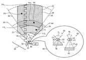
- FIG. 1schematically shows a plan view of a TOF 3D imager 20 comprising a near TOF camera 30 , a far TOF camera 40 , and a light source 50 . Details of the TOF cameras are shown in an inset 90 .
- Near TOF camera 30comprises an optical system represented by a lens 31 that collects light from objects imaged by the near TOF camera and images the collected light on a photosensor 32 .
- Optical system 31has an optical center 33 and a focal length N that together with photosensor 32 define a wide-angle FOV for the near TOF camera that is characterized by relatively large, optionally fixed, horizontal view angle ⁇ N defined by lines 44 .
- Numeral 44 designating the lines that define view angle ⁇ N of the wide angle FOV of near TOF camera 30is also used to refer to the FOV, which may be referred to as “near FOV”, of the near TOF camera 30 .
- Optical system 31also includes a shutter 35 for shuttering near TOF camera 30 open and closed.
- far TOF camera 40comprises an optical system represented by a lens 41 that collects light from objects in the camera's FOV and images the collected light on a photosensor 42 .
- the optical systemhas an optical center 43 and a focal length f F that together with photosensor 42 define a narrow-angle FOV for the far TOF camera that is characterized by relatively large, optionally fixed, horizontal view angle ⁇ F defined by lines 34 .
- Numeral 34 designating the lines that define view angle ⁇ F of the wide angle FOV of far TOF camera 40is also used to refer to the FOV, which may be referred to as “far FOV”, of the far TOF camera.
- Optical system 41also includes a shutter 45 for shuttering far TOF camera open and closed.
- Light source 50is controllable by a controller 60 to radiate a train of light pulses to illuminate objects in near and far FOVs 44 and 34 .
- Light pulses radiated by light source 50are schematically represented by square “pulses” labeled with a numeral 52 .
- light pulses 52may comprise light provided by a suitable light emitting diode (LED) and/or laser from any portion of the spectrum, usually, light pulses 52 are near infrared (NIR) light pulses.
- LEDlight emitting diode
- NIRnear infrared
- controller 60controls near shutter 35 to shutter open near TOF camera 30 for a short exposure period having duration N .
- Nlight reflected from the light pulse by features in near FOV 44 that reaches near TOF camera 30 is imaged by lens 31 onto photosensor 32 .
- the imaged lightis registered by the near TOF camera and is used to determine how long it takes light in light pulse 52 to travel round trip from light source 50 to the features and back to near TOF camera 30 .
- the round trip time and the speed of lightare used to determine how far the features are from the near TOF camera and therefore from TOF 3D imager 20 .
- controller 60controls shutter 45 in far TOF camera 40 to shutter open the far TOF camera for a short exposure period having duration F following a delay FD after each pulse 52 is radiated by light source 50 .
- the far TOF cameraimages and registers light reflected from the light pulse that reaches the far TOF camera during the exposure period and uses the registered light to determine distances from TOF 3D imager 20 to features in far FOV 34 .
- Far TOF camera 40because of its narrow-angle FOV 34 , images features farther from TOF 3D imager 20 with better spatial resolution than near TOF camera 30 , but images a relatively small volume of space near to TOF 3D imager 20 .
- near TOF camera 30because of its relatively wide-angle FOV 44 is able to image a relatively large volume of space near to TOF 3D imager 20 and may be configured to image close features with acceptable spatial resolution.
- imaging range lower and upper boundsare established for near and far TOF cameras 30 and 40 .
- the lower and upper range bounds associated with near TOF camera 30be represented by NR L and NR U respectively.
- the lower and upper bounds for near TOF camera 30are schematically shown in FIG. 1 by dashed lines that are labeled NR L and NR U .
- the lower and upper range bounds associated with far TOF camera 40be represented by FR L and FR U respectively.
- the lower and upper bounds for far camera 40are schematically shown in FIG. 1 by dashed lines that are labeled FR L and FR U .
- View angles ⁇ N and ⁇ F , and range bounds NR L , NR U , FR L , and FR Uoptionally define an active space schematically outlined by a bold dashed line 22 for TOF 3D imager 20 .
- Numeral 22 that labels the dashed lines that outline the active space of TOF 3D imager 20is also used to refer to the active space.
- view angle ⁇ N for wide-angle FOV 44 of near TOF camera 30is determined so that active space 22 has an advantageous width close to TOF 3D imager 20 .
- Near and far upper bounds NR U and FR U and view angle ⁇ F for narrow-angle FOV 34 of far TOF camera 40are determined so that near and far TOF cameras 30 and 40 image objects at distances NR U and FR U respectively with substantially a same spatial resolution.
- Active space 22therefore comprises three zones: a near zone 23 , an intermediate zone 24 and a far zone 25 .
- an active spacefor example for playing full-body 3D computer games active space 22 advantageously extends from NR L equal to about 0.80 m to FR U equal to about 3 m from TOF 3D imager 20 . If at 0.80 m from the TOF 3D imager 20 active space 22 is about 1 m wide, then advantageously, near TOF camera 30 has a view angle ⁇ N equal to about 62.5°.
- Controller 60controls TOF 3D imager 20 and processes distance information provided by distance images acquired by near and far TOF cameras 30 and 40 responsive to the lower and upper bounds N RL , N RU , F RL , and F RU and zones 23 , 24 and 25 that they define.
- controller 60controls TOF 3D imager 20 using a delay ND and duration of exposure period N for near TOF camera 30 substantially equal respectively to delay FD and exposure period F for far TOF camera 40 . Under these conditions of substantial equality, both TOF cameras acquire images for features in active space 22 over a same range of distances from the TOF 3D imager.
- controller 60shutters far TOF camera 40 with FD and F determined so that far TOF camera 40 images a feature present in far FOV 34 with light from light source 50 only if the feature's distance from the near TOF camera is between FR L and FR U .
- controllershutters near TOF camera 30 with ND and F determined so that near TOF camera 30 images a feature present in near FOV 44 with light from light source 50 only if the feature's distance from the near TOF camera is between NR L and NR U .
- controller 60may provide acceptable distance measurements for features in zone 23 using distance images provided only by near TOF camera 30 .
- controller 60may provide acceptable distance measurements for features in zone 25 using distance images provided only by far TOF camera 40 .
- the controlleroptionally uses data provided by both near and far TOF cameras.
- Solid circles 73 , 74 and 75schematically represent by features at locations in zones 23 , 24 and 25
- controllerdesignates one of the TOF cameras as a “prime” TOF camera.
- the letter “C”represents the prime camera.
- the letter C*represents the other camera, which may be referred to as a “secondary” camera. It is assumed that distance from TOF 3D imager 20 is to be determined for a feature imaged on a pixel P j of the prime camera C.
- the prime camerais assumed to be near TOF camera 30
- the feature imaged on pixel P jis assumed to be feature 74 shown in FIG. 1 located in intermediate zone 24 .
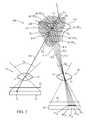
- FIG. 2schematically shows a greatly enlarged view of near and far TOF cameras 30 and 40 , a region 100 of intermediate zone 24 in which feature 74 is located and pixel P j on which feature 74 is imaged on photosensor 32 of prime camera C, near TOF camera 30 .
- feature 74is assumed to be constrained to lie along a line in space, an imaging line 101 , also referred to as a prime imaging line 101 , that passes from the feature through optical center 33 of near TOF camera 30 and intersect pixel P j .
- a trail distance for feature 74is a distance “dCP j ” determined from the distance image of feature 74 acquired by pixel P j .
- a distance “d” along prime imaging line 101is assumed to be an actual distance along the imaging line at which feature 74 is located with a probability given by a probability distribution function (d;dCP j , ⁇ j ), where ⁇ j is a measure of an error associated with trial distance dCP j .
- Shot and read noisetypically generate an error associated with a trail distance.
- a segment of imaging line 101 between witness lines 110 and 111schematically represents a magnitude of an error associated with dCP j .
- probability distribution (d;dCP j , ⁇ j )is assumed to be a normal distribution represented by a curve 120 shown along imaging line 101 having a maximum at distance dCP j and a standard deviation ⁇ j .
- a pixel P* jm in photosensor 42 of far TOF camera 40is determined on which region R jm would be imaged, were it located in the region.
- Mis arbitrarily shown equal to five.
- Regions R jmare schematically indicated along the segment of prime imaging line 101 between witness lines 110 and 111 by diamond icons labeled by corresponding distances d j1 , d j2 , . . . d j5 , corresponding respectively to R j1 , R j2 , . . . R j5 .
- Pixel P* jmlies at an end of an imaging line IL m , hereinafter also referred to as a secondary imaging line IL m that extends from d jm through optical center 43 of secondary camera, far TOF camera 40 .
- a distance image acquired by pixel P* jmprovides a distance dC*P* jm along its associated imaging line IL m for a feature imaged on the pixel, and that the distance dC*P* jm is associated with an error ⁇ * jm .
- Distances dC*P* jmare graphically represented by circle icons labeled by distances dC*P* jm , (1 ⁇ m ⁇ 5) along secondary imaging lines IL m .
- a probability that a distance d* m along imaging line IL m for the feature imaged on pixel P* jm is the actual distance for the featurebe given by a probability distribution function (d* m ; dC*P* jm , ⁇ * jm ).
- a probability distribution function(d* m ; dC*P* jm , ⁇ * jm )
- a probability that the d* jm is the actual distance of the feature imaged on pixel P* jm from far camera 40is (d* jm ; dC*P* jm , ⁇ * jm ).
- controller 60determines that a distance DCP j for the feature, for example feature 74 , imaged on pixel P j of prime, near TOF camera 30 , is a distance d m (1 ⁇ m ⁇ M) that maximizes: (d m ;dCP j , ⁇ j ) ⁇ (d* jm ;dC*P* jm , ⁇ * jm ).
- near TOF camera 30is designated the prime camera and far TOF camera 40 the secondary camera
- the procedure for determining distanceis generally substantially independent of which camera is the prime camera.
- the roles of the camerasmay be reversed, with far TOF camera 40 designated the prime camera and near TOF camera the secondary camera and prime imaging line 101 associated with the far TOF camera.
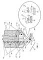
- FIGS. 3A and 3Bshow a flow diagram 200 of an algorithm, also referred to by the numeral 200 , by which TOF 3D imager 20 processes information from images of active space 22 acquired by near and far TOF cameras 30 and 40 to determine distances to features in active space 22 and provide a range image for features in the active space.
- controller 60determines whether to adjust TOF 3D imager 20 to operate in a zoom-out mode or in a zoom-in mode. Adjusting the TOF 3D imager comprises determining which camera, near TOF camera 30 , (the wide-angle FOV, zoom-out camera) or far TOF camera 40 (the narrow-angle FOV, zoom-in camera), is designated the prime camera for processing distance information provided by the cameras.
- the discussion above with respect to FIG. 1provides an example of a role of a prime camera in determining distances to features in active space 22 ( FIG. 1 ).
- controller 60estimates from distances provided by near and far TOF cameras 30 and 40 a number of features of interest present in each of near, overlap and far zones zones 23 , 24 , and 25 in active space 22 .
- the controllerdetermines zoom-in or zoom-out in response to the estimated numbers of features.
- controller 60adjusts TOF 3D imager 20 to operate in a zoom-in mode with near TOF camera 30 the prime camera, or zoom-out mode with far TOF camera 40 the prime camera, respectively.
- controller 60leaves the TOF 3D imager operating in a zoom mode in which it was operating prior to estimating the number of features of interest or determines the zoom mode in accordance with a predetermined default procedure.
- controller 60sets intensity of light pulses radiated by light source 50 to match the choice of zoom-mode. If the zoom mode is zoom-out, the controller optionally sets the intensity to a moderate level to reduce the probability that features in near zone 23 close to TOF 3D imager 20 may reflect amounts of light from the light pulses back to near and far TOF cameras 30 and 40 that saturates pixels in the TOF cameras. If the zoom mode is zoom-in, controller 60 optionally sets the intensity of radiated pulses greater than the moderate intensity chosen for the zoom-out mode to reduce a probability that features in far zone 25 , relatively far from TOF 3D imager 20 , do not reflect sufficient light back to the TOF cameras for acceptable imaging. An intermediate intensity is optionally determined for a situation where a relatively large number of features of interest are found in intermediate zone 24 .
- the controllerinitializes to zero an index “j” that designates pixels in prime camera C, which may be either near TOF camera 30 or far TOF camera 40 .
- Index jhas a maximum value equal to J, which represents a total number of pixels in near TOF camera 30 .
- the controllerincreases the index by one.
- controller 60determines a trail distance dCP j from a distance image acquired by pixel P j in prime camera C for a feature in active space 22 .
- the controlleroptionally determines in a decision block 216 whether the trial distance dCP j indicates if the feature imaged on pixel P j appears to be located in intermediate zone 24 . If it is, optionally in a block 218 , controller 60 uses distance information from both prime camera C and secondary camera C* to determine a distance DCP j for the feature imaged on P j . Optionally, the controller determines from the geometry of near and far TOF cameras 30 and 40 and their positions relative to each other in TOF 3D imager 20 , which pixel P* k:j ⁇ k corresponds to pixel P j , and images substantially a same feature that pixel P j images.
- the weighting factorsmay for example weigh information from the prime camera C more than information from the secondary camera C*, or weigh the trial distances by a function of their respective errors.
- controller 60optionally continues from block 218 to block 208 via a decision block 224 to increase index j or to block 226 to provide a range image for active space 22 and proceed to block 228 to end the process.
- controller 60finds that trial distance dCP j does not indicate that the feature is located in intermediate zone 24 then either the trial distance indicates that the feature is located in C*-zone, the zone in active space 22 associated with secondary camera C*, or the trial distance is invalid and the controller proceeds optionally to a block 220 .
- controlleroptionally proceeds to block 224 and thereafter to return to block 208 to repeat the procedure for a next pixel in prime camera C, or to block 226 to provide a range image and then end the procedure.
- controllermay proceed to repeatedly execute algorithm 200 for each set of images acquired for the active space during the game.
- each of the verbs, “comprise” “include” and “have”, and conjugates thereof,are used to indicate that the object or objects of the verb are not necessarily a complete listing of components, elements or parts of the subject or subjects of the verb.
Landscapes
- Physics & Mathematics (AREA)
- Engineering & Computer Science (AREA)
- Electromagnetism (AREA)
- Remote Sensing (AREA)
- General Physics & Mathematics (AREA)
- Radar, Positioning & Navigation (AREA)
- Computer Networks & Wireless Communication (AREA)
- Multimedia (AREA)
- Signal Processing (AREA)
- Length Measuring Devices By Optical Means (AREA)
- Studio Devices (AREA)
- Testing, Inspecting, Measuring Of Stereoscopic Televisions And Televisions (AREA)
- Measurement Of Optical Distance (AREA)
- Optical Radar Systems And Details Thereof (AREA)
Abstract
Description


Claims (20)
Priority Applications (6)
| Application Number | Priority Date | Filing Date | Title |
|---|---|---|---|
| US13/356,618US9720089B2 (en) | 2012-01-23 | 2012-01-23 | 3D zoom imager |
| EP13740760.7AEP2807826B1 (en) | 2012-01-23 | 2013-01-08 | 3d zoom imager |
| KR1020147023398AKR101992511B1 (en) | 2012-01-23 | 2013-01-08 | 3d zoom imager |
| PCT/US2013/020693WO2013112284A1 (en) | 2012-01-23 | 2013-01-08 | 3d zoom imager |
| JP2014554728AJP2015510586A (en) | 2012-01-23 | 2013-01-08 | 3D zoom imaging device |
| CN201380006368.2ACN104094594B (en) | 2012-01-23 | 2013-01-08 | 3D zoom imager |
Applications Claiming Priority (1)
| Application Number | Priority Date | Filing Date | Title |
|---|---|---|---|
| US13/356,618US9720089B2 (en) | 2012-01-23 | 2012-01-23 | 3D zoom imager |
Publications (2)
| Publication Number | Publication Date |
|---|---|
| US20130188022A1 US20130188022A1 (en) | 2013-07-25 |
| US9720089B2true US9720089B2 (en) | 2017-08-01 |
Family
ID=48796901
Family Applications (1)
| Application Number | Title | Priority Date | Filing Date |
|---|---|---|---|
| US13/356,618Active2034-12-22US9720089B2 (en) | 2012-01-23 | 2012-01-23 | 3D zoom imager |
Country Status (6)
| Country | Link |
|---|---|
| US (1) | US9720089B2 (en) |
| EP (1) | EP2807826B1 (en) |
| JP (1) | JP2015510586A (en) |
| KR (1) | KR101992511B1 (en) |
| CN (1) | CN104094594B (en) |
| WO (1) | WO2013112284A1 (en) |
Cited By (3)
| Publication number | Priority date | Publication date | Assignee | Title |
|---|---|---|---|---|
| US10848746B2 (en) | 2018-12-14 | 2020-11-24 | Samsung Electronics Co., Ltd. | Apparatus including multiple cameras and image processing method |
| US11172112B2 (en) | 2019-09-09 | 2021-11-09 | Embedtek, LLC | Imaging system including a non-linear reflector |
| EP3939834A4 (en)* | 2019-03-11 | 2022-08-31 | Koito Manufacturing Co., Ltd. | CONTROL CAMERA, MOTOR VEHICLE, HEADLIGHT, OBJECT RECOGNITION SYSTEM, ARITHMETIC PROCESSING UNIT, OBJECT RECOGNITION METHOD, IMAGE DISPLAY SYSTEM, DETECTION METHOD, IMAGE CAPTURE DEVICE AND IMAGE PROCESSING DEVICE |
Families Citing this family (33)
| Publication number | Priority date | Publication date | Assignee | Title |
|---|---|---|---|---|
| US8988508B2 (en)* | 2010-09-24 | 2015-03-24 | Microsoft Technology Licensing, Llc. | Wide angle field of view active illumination imaging system |
| US10154177B2 (en)* | 2012-10-04 | 2018-12-11 | Cognex Corporation | Symbology reader with multi-core processor |
| US9426451B2 (en)* | 2013-03-15 | 2016-08-23 | Digimarc Corporation | Cooperative photography |
| DE112014005645A5 (en) | 2013-12-13 | 2016-09-08 | Fts Computertechnik Gmbh | Method and device for observing the environment of a vehicle |
| EP4016981A3 (en)* | 2013-12-24 | 2022-09-21 | Sony Depthsensing Solutions | A time-of-flight camera system |
| WO2016025962A1 (en)* | 2014-08-15 | 2016-02-18 | The University Of Akron | Device and method for three-dimensional video communication |
| US9854226B2 (en) | 2014-12-22 | 2017-12-26 | Google Inc. | Illuminator for camera system having three dimensional time-of-flight capture with movable mirror element |
| US9918073B2 (en) | 2014-12-22 | 2018-03-13 | Google Llc | Integrated camera system having two dimensional image capture and three dimensional time-of-flight capture with movable illuminated region of interest |
| US9635231B2 (en) | 2014-12-22 | 2017-04-25 | Google Inc. | Time-of-flight camera system and method to improve measurement quality of weak field-of-view signal regions |
| US9674415B2 (en)* | 2014-12-22 | 2017-06-06 | Google Inc. | Time-of-flight camera system with scanning illuminator |
| US20160182891A1 (en)* | 2014-12-22 | 2016-06-23 | Google Inc. | Integrated Camera System Having Two Dimensional Image Capture and Three Dimensional Time-of-Flight Capture With A Partitioned Field of View |
| GB2541101A (en)* | 2015-06-23 | 2017-02-08 | Bosch Gmbh Robert | Method and camera system for determining the distance of objects in relation to a vehicle |
| GB201511551D0 (en) | 2015-07-01 | 2015-08-12 | St Microelectronics Res & Dev | Photonics device |
| US11204425B2 (en)* | 2015-12-21 | 2021-12-21 | Koito Manufacturing Co., Ltd. | Image acquisition device for vehicles and vehicle provided with same |
| EP3396412A4 (en) | 2015-12-21 | 2019-08-21 | Koito Manufacturing Co., Ltd. | Vehicular sensor, and vehicle provided with same |
| EP3396410A4 (en) | 2015-12-21 | 2019-08-21 | Koito Manufacturing Co., Ltd. | Image acquisition device for vehicles, control device, vehicle provided with image acquisition device for vehicles and control device, and image acquisition method for vehicles |
| EP3396413A4 (en) | 2015-12-21 | 2019-08-21 | Koito Manufacturing Co., Ltd. | Image acquisition device for vehicles, control device, vehicle provided with image acquisition device for vehicles and control device, and image acquisition method for vehicles |
| CN108431629B (en) | 2015-12-21 | 2022-07-08 | 株式会社小糸制作所 | Vehicle image acquisition device, control device, vehicle including vehicle image acquisition device or control device, and vehicle image acquisition method |
| EP3646581A1 (en)* | 2017-06-30 | 2020-05-06 | PCMS Holdings, Inc. | Method and apparatus for generating and displaying 360-degree video based on eye tracking and physiological measurements |
| US10785400B2 (en) | 2017-10-09 | 2020-09-22 | Stmicroelectronics (Research & Development) Limited | Multiple fields of view time of flight sensor |
| US10232800B1 (en) | 2017-11-10 | 2019-03-19 | Denson Corporation | Camera module |
| JP7106855B2 (en) | 2017-11-10 | 2022-07-27 | 株式会社デンソー | The camera module |
| US10406995B2 (en)* | 2017-11-10 | 2019-09-10 | Denso Corporation | Camera module |
| US10534253B2 (en) | 2017-11-10 | 2020-01-14 | Denso Corporation | Camera module which includes lens units and configured to be mounted on inside of windshiled of vehicle |
| US10627606B2 (en) | 2017-11-10 | 2020-04-21 | Denso Corporation | Camera module |
| US10661725B2 (en) | 2017-11-10 | 2020-05-26 | Denso Corporation | Camera module |
| US20190146067A1 (en)* | 2017-11-14 | 2019-05-16 | Continental Automotive Systems, Inc. | Flash lidar sensor assembly |
| CN107872665A (en)* | 2017-12-07 | 2018-04-03 | 深圳市趣创科技有限公司 | Mobile phone 3D camera functions and system |
| JP7150508B2 (en)* | 2018-07-24 | 2022-10-11 | 株式会社東芝 | Imaging system for railway vehicles |
| WO2021066219A1 (en)* | 2019-10-01 | 2021-04-08 | 엘지전자 주식회사 | Mobile terminal |
| CN113163112B (en)* | 2021-03-25 | 2022-12-13 | 中国电子科技集团公司第三研究所 | Fusion focus control method and system |
| WO2023038264A1 (en)* | 2021-09-13 | 2023-03-16 | 삼성전자 주식회사 | Electronic device for generating three-dimensional photo based on images acquired from plurality of cameras, and method therefor |
| CN114112964B (en)* | 2021-11-10 | 2023-09-12 | 中国科学院上海技术物理研究所 | A Fourier transform infrared spectrometer multi-field automatic measurement system and method |
Citations (189)
| Publication number | Priority date | Publication date | Assignee | Title |
|---|---|---|---|---|
| US4402608A (en) | 1980-10-02 | 1983-09-06 | Solid Photography Inc. | Room scanning system using multiple camera and projector sensors |
| US4627620A (en) | 1984-12-26 | 1986-12-09 | Yang John P | Electronic athlete trainer for improving skills in reflex, speed and accuracy |
| US4630910A (en) | 1984-02-16 | 1986-12-23 | Robotic Vision Systems, Inc. | Method of measuring in three-dimensions at high speed |
| US4645458A (en) | 1985-04-15 | 1987-02-24 | Harald Phillip | Athletic evaluation and training apparatus |
| US4695953A (en) | 1983-08-25 | 1987-09-22 | Blair Preston E | TV animation interactively controlled by the viewer |
| US4702475A (en) | 1985-08-16 | 1987-10-27 | Innovating Training Products, Inc. | Sports technique and reaction training system |
| US4711543A (en) | 1986-04-14 | 1987-12-08 | Blair Preston E | TV animation interactively controlled by the viewer |
| US4751642A (en) | 1986-08-29 | 1988-06-14 | Silva John M | Interactive sports simulation system with physiological sensing and psychological conditioning |
| US4796997A (en) | 1986-05-27 | 1989-01-10 | Synthetic Vision Systems, Inc. | Method and system for high-speed, 3-D imaging of an object at a vision station |
| US4809065A (en) | 1986-12-01 | 1989-02-28 | Kabushiki Kaisha Toshiba | Interactive system and related method for displaying data to produce a three-dimensional image of an object |
| US4817950A (en) | 1987-05-08 | 1989-04-04 | Goo Paul E | Video game control unit and attitude sensor |
| US4843568A (en) | 1986-04-11 | 1989-06-27 | Krueger Myron W | Real time perception of and response to the actions of an unencumbered participant/user |
| US4893183A (en) | 1988-08-11 | 1990-01-09 | Carnegie-Mellon University | Robotic vision system |
| US4901362A (en) | 1988-08-08 | 1990-02-13 | Raytheon Company | Method of recognizing patterns |
| US4925189A (en) | 1989-01-13 | 1990-05-15 | Braeunig Thomas F | Body-mounted video game exercise device |
| US5005083A (en) | 1988-05-19 | 1991-04-02 | Siemens Aktiengesellschaft | FLIR system with two optical channels for observing a wide and a narrow field of view |
| US5101444A (en) | 1990-05-18 | 1992-03-31 | Panacea, Inc. | Method and apparatus for high speed object location |
| US5148154A (en) | 1990-12-04 | 1992-09-15 | Sony Corporation Of America | Multi-dimensional user interface |
| US5184295A (en) | 1986-05-30 | 1993-02-02 | Mann Ralph V | System and method for teaching physical skills |
| WO1993010708A1 (en) | 1991-12-03 | 1993-06-10 | French Sportech Corporation | Interactive video testing and training system |
| US5229756A (en) | 1989-02-07 | 1993-07-20 | Yamaha Corporation | Image control apparatus |
| US5229754A (en) | 1990-02-13 | 1993-07-20 | Yazaki Corporation | Automotive reflection type display apparatus |
| US5239464A (en) | 1988-08-04 | 1993-08-24 | Blair Preston E | Interactive video system providing repeated switching of multiple tracks of actions sequences |
| US5239463A (en) | 1988-08-04 | 1993-08-24 | Blair Preston E | Method and apparatus for player interaction with animated characters and objects |
| EP0583061A2 (en) | 1992-07-10 | 1994-02-16 | The Walt Disney Company | Method and apparatus for providing enhanced graphics in a virtual world |
| US5288078A (en) | 1988-10-14 | 1994-02-22 | David G. Capper | Control interface apparatus |
| US5295491A (en) | 1991-09-26 | 1994-03-22 | Sam Technology, Inc. | Non-invasive human neurocognitive performance capability testing method and system |
| US5320538A (en) | 1992-09-23 | 1994-06-14 | Hughes Training, Inc. | Interactive aircraft training system and method |
| US5347306A (en) | 1993-12-17 | 1994-09-13 | Mitsubishi Electric Research Laboratories, Inc. | Animated electronic meeting place |
| US5385519A (en) | 1994-04-19 | 1995-01-31 | Hsu; Chi-Hsueh | Running machine |
| US5405152A (en) | 1993-06-08 | 1995-04-11 | The Walt Disney Company | Method and apparatus for an interactive video game with physical feedback |
| US5417210A (en) | 1992-05-27 | 1995-05-23 | International Business Machines Corporation | System and method for augmentation of endoscopic surgery |
| US5423554A (en) | 1993-09-24 | 1995-06-13 | Metamedia Ventures, Inc. | Virtual reality game method and apparatus |
| US5454043A (en) | 1993-07-30 | 1995-09-26 | Mitsubishi Electric Research Laboratories, Inc. | Dynamic and static hand gesture recognition through low-level image analysis |
| US5469740A (en) | 1989-07-14 | 1995-11-28 | Impulse Technology, Inc. | Interactive video testing and training system |
| JPH0844490A (en) | 1994-07-28 | 1996-02-16 | Matsushita Electric Ind Co Ltd | Interface device |
| US5495576A (en) | 1993-01-11 | 1996-02-27 | Ritchey; Kurtis J. | Panoramic image based virtual reality/telepresence audio-visual system and method |
| US5516105A (en) | 1994-10-06 | 1996-05-14 | Exergame, Inc. | Acceleration activated joystick |
| US5524637A (en) | 1994-06-29 | 1996-06-11 | Erickson; Jon W. | Interactive system for measuring physiological exertion |
| US5534917A (en) | 1991-05-09 | 1996-07-09 | Very Vivid, Inc. | Video image based control system |
| US5563988A (en) | 1994-08-01 | 1996-10-08 | Massachusetts Institute Of Technology | Method and system for facilitating wireless, full-body, real-time user interaction with a digitally represented visual environment |
| US5577981A (en) | 1994-01-19 | 1996-11-26 | Jarvik; Robert | Virtual reality exercise machine and computer controlled video system |
| US5580249A (en) | 1994-02-14 | 1996-12-03 | Sarcos Group | Apparatus for simulating mobility of a human |
| US5594469A (en) | 1995-02-21 | 1997-01-14 | Mitsubishi Electric Information Technology Center America Inc. | Hand gesture machine control system |
| US5597309A (en) | 1994-03-28 | 1997-01-28 | Riess; Thomas | Method and apparatus for treatment of gait problems associated with parkinson's disease |
| US5617312A (en) | 1993-11-19 | 1997-04-01 | Hitachi, Ltd. | Computer system that enters control information by means of video camera |
| US5616078A (en) | 1993-12-28 | 1997-04-01 | Konami Co., Ltd. | Motion-controlled video entertainment system |
| WO1997017598A1 (en) | 1995-11-06 | 1997-05-15 | Impulse Technology, Inc. | System for continuous monitoring of physical activity during unrestricted movement |
| US5638300A (en) | 1994-12-05 | 1997-06-10 | Johnson; Lee E. | Golf swing analysis system |
| US5641288A (en) | 1996-01-11 | 1997-06-24 | Zaenglein, Jr.; William G. | Shooting simulating process and training device using a virtual reality display screen |
| US5682196A (en) | 1995-06-22 | 1997-10-28 | Actv, Inc. | Three-dimensional (3D) video presentation system providing interactive 3D presentation with personalized audio responses for multiple viewers |
| US5682229A (en) | 1995-04-14 | 1997-10-28 | Schwartz Electro-Optics, Inc. | Laser range camera |
| US5690582A (en) | 1993-02-02 | 1997-11-25 | Tectrix Fitness Equipment, Inc. | Interactive exercise apparatus |
| US5703367A (en) | 1994-12-09 | 1997-12-30 | Matsushita Electric Industrial Co., Ltd. | Human occupancy detection method and system for implementing the same |
| US5704837A (en) | 1993-03-26 | 1998-01-06 | Namco Ltd. | Video game steering system causing translation, rotation and curvilinear motion on the object |
| US5715834A (en) | 1992-11-20 | 1998-02-10 | Scuola Superiore Di Studi Universitari & Di Perfezionamento S. Anna | Device for monitoring the configuration of a distal physiological unit for use, in particular, as an advanced interface for machine and computers |
| JPH1139596A (en) | 1997-07-17 | 1999-02-12 | Fuji Heavy Ind Ltd | Outside monitoring device |
| US5875108A (en) | 1991-12-23 | 1999-02-23 | Hoffberg; Steven M. | Ergonomic man-machine interface incorporating adaptive pattern recognition based control system |
| US5877803A (en) | 1997-04-07 | 1999-03-02 | Tritech Mircoelectronics International, Ltd. | 3-D image detector |
| US5913727A (en) | 1995-06-02 | 1999-06-22 | Ahdoot; Ned | Interactive movement and contact simulation game |
| US5933125A (en) | 1995-11-27 | 1999-08-03 | Cae Electronics, Ltd. | Method and apparatus for reducing instability in the display of a virtual environment |
| WO1999044698A2 (en) | 1998-03-03 | 1999-09-10 | Arena, Inc. | System and method for tracking and assessing movement skills in multidimensional space |
| US5980256A (en) | 1993-10-29 | 1999-11-09 | Carmein; David E. E. | Virtual reality system with enhanced sensory apparatus |
| US5989157A (en) | 1996-08-06 | 1999-11-23 | Walton; Charles A. | Exercising system with electronic inertial game playing |
| US5995649A (en) | 1996-09-20 | 1999-11-30 | Nec Corporation | Dual-input image processor for recognizing, isolating, and displaying specific objects from the input images |
| US6005548A (en) | 1996-08-14 | 1999-12-21 | Latypov; Nurakhmed Nurislamovich | Method for tracking and displaying user's spatial position and orientation, a method for representing virtual reality for a user, and systems of embodiment of such methods |
| US6009210A (en) | 1997-03-05 | 1999-12-28 | Digital Equipment Corporation | Hands-free interface to a virtual reality environment using head tracking |
| US6054991A (en) | 1991-12-02 | 2000-04-25 | Texas Instruments Incorporated | Method of modeling player position and movement in a virtual reality system |
| US6066075A (en) | 1995-07-26 | 2000-05-23 | Poulton; Craig K. | Direct feedback controller for user interaction |
| US6072494A (en) | 1997-10-15 | 2000-06-06 | Electric Planet, Inc. | Method and apparatus for real-time gesture recognition |
| US6073489A (en) | 1995-11-06 | 2000-06-13 | French; Barry J. | Testing and training system for assessing the ability of a player to complete a task |
| US6077201A (en) | 1998-06-12 | 2000-06-20 | Cheng; Chau-Yang | Exercise bicycle |
| US6100896A (en) | 1997-03-24 | 2000-08-08 | Mitsubishi Electric Information Technology Center America, Inc. | System for designing graphical multi-participant environments |
| US6101289A (en) | 1997-10-15 | 2000-08-08 | Electric Planet, Inc. | Method and apparatus for unencumbered capture of an object |
| US6128003A (en) | 1996-12-20 | 2000-10-03 | Hitachi, Ltd. | Hand gesture recognition system and method |
| US6130677A (en) | 1997-10-15 | 2000-10-10 | Electric Planet, Inc. | Interactive computer vision system |
| JP2000292538A (en) | 1999-04-07 | 2000-10-20 | Mitsubishi Electric Corp | Obstacle detection device for vehicles |
| US6141463A (en) | 1997-10-10 | 2000-10-31 | Electric Planet Interactive | Method and system for estimating jointed-figure configurations |
| US6147678A (en) | 1998-12-09 | 2000-11-14 | Lucent Technologies Inc. | Video hand image-three-dimensional computer interface with multiple degrees of freedom |
| US6152856A (en) | 1996-05-08 | 2000-11-28 | Real Vision Corporation | Real time simulation using position sensing |
| US6159100A (en) | 1998-04-23 | 2000-12-12 | Smith; Michael D. | Virtual reality game |
| US6173066B1 (en) | 1996-05-21 | 2001-01-09 | Cybernet Systems Corporation | Pose determination and tracking by matching 3D objects to a 2D sensor |
| US6181343B1 (en) | 1997-12-23 | 2001-01-30 | Philips Electronics North America Corp. | System and method for permitting three-dimensional navigation through a virtual reality environment using camera-based gesture inputs |
| US6188777B1 (en) | 1997-08-01 | 2001-02-13 | Interval Research Corporation | Method and apparatus for personnel detection and tracking |
| US6215890B1 (en) | 1997-09-26 | 2001-04-10 | Matsushita Electric Industrial Co., Ltd. | Hand gesture recognizing device |
| US6215898B1 (en) | 1997-04-15 | 2001-04-10 | Interval Research Corporation | Data processing system and method |
| US6226396B1 (en) | 1997-07-31 | 2001-05-01 | Nec Corporation | Object extraction method and system |
| US6229913B1 (en) | 1995-06-07 | 2001-05-08 | The Trustees Of Columbia University In The City Of New York | Apparatus and methods for determining the three-dimensional shape of an object using active illumination and relative blurring in two-images due to defocus |
| US6256400B1 (en) | 1998-09-28 | 2001-07-03 | Matsushita Electric Industrial Co., Ltd. | Method and device for segmenting hand gestures |
| US6283860B1 (en) | 1995-11-07 | 2001-09-04 | Philips Electronics North America Corp. | Method, system, and program for gesture based option selection |
| US6289112B1 (en) | 1997-08-22 | 2001-09-11 | International Business Machines Corporation | System and method for determining block direction in fingerprint images |
| US6299308B1 (en) | 1999-04-02 | 2001-10-09 | Cybernet Systems Corporation | Low-cost non-imaging eye tracker system for computer control |
| US6308565B1 (en) | 1995-11-06 | 2001-10-30 | Impulse Technology Ltd. | System and method for tracking and assessing movement skills in multidimensional space |
| US6316934B1 (en) | 1998-09-17 | 2001-11-13 | Netmor Ltd. | System for three dimensional positioning and tracking |
| JP2001330665A (en) | 2000-05-18 | 2001-11-30 | Fujitsu Ten Ltd | On-vehicle object detector using radar and image processing |
| US6363160B1 (en) | 1999-01-22 | 2002-03-26 | Intel Corporation | Interface using pattern recognition and tracking |
| US6384819B1 (en) | 1997-10-15 | 2002-05-07 | Electric Planet, Inc. | System and method for generating an animatable character |
| US6411744B1 (en) | 1997-10-15 | 2002-06-25 | Electric Planet, Inc. | Method and apparatus for performing a clean background subtraction |
| US6430997B1 (en) | 1995-11-06 | 2002-08-13 | Trazer Technologies, Inc. | System and method for tracking and assessing movement skills in multidimensional space |
| US6476834B1 (en) | 1999-05-28 | 2002-11-05 | International Business Machines Corporation | Dynamic creation of selectable items on surfaces |
| US6496598B1 (en) | 1997-09-02 | 2002-12-17 | Dynamic Digital Depth Research Pty. Ltd. | Image processing method and apparatus |
| US6503195B1 (en) | 1999-05-24 | 2003-01-07 | University Of North Carolina At Chapel Hill | Methods and systems for real-time structured light depth extraction and endoscope using real-time structured light depth extraction |
| JP2003501635A (en) | 1999-05-26 | 2003-01-14 | ローベルト ボッシュ ゲゼルシャフト ミット ベシュレンクテル ハフツング | Object detection system |
| US6539931B2 (en) | 2001-04-16 | 2003-04-01 | Koninklijke Philips Electronics N.V. | Ball throwing assistant |
| US6570555B1 (en) | 1998-12-30 | 2003-05-27 | Fuji Xerox Co., Ltd. | Method and apparatus for embodied conversational characters with multimodal input/output in an interface device |
| US6633294B1 (en) | 2000-03-09 | 2003-10-14 | Seth Rosenthal | Method and apparatus for using captured high density motion for animation |
| US6640202B1 (en) | 2000-05-25 | 2003-10-28 | International Business Machines Corporation | Elastic sensor mesh system for 3-dimensional measurement, mapping and kinematics applications |
| US6661918B1 (en) | 1998-12-04 | 2003-12-09 | Interval Research Corporation | Background estimation and segmentation based on range and color |
| US6681031B2 (en) | 1998-08-10 | 2004-01-20 | Cybernet Systems Corporation | Gesture-controlled interfaces for self-service machines and other applications |
| US6714665B1 (en) | 1994-09-02 | 2004-03-30 | Sarnoff Corporation | Fully automated iris recognition system utilizing wide and narrow fields of view |
| US6731799B1 (en) | 2000-06-01 | 2004-05-04 | University Of Washington | Object segmentation with background extraction and moving boundary techniques |
| US6738066B1 (en) | 1999-07-30 | 2004-05-18 | Electric Plant, Inc. | System, method and article of manufacture for detecting collisions between video images generated by a camera and an object depicted on a display |
| US6788809B1 (en) | 2000-06-30 | 2004-09-07 | Intel Corporation | System and method for gesture recognition in three dimensions using stereo imaging and color vision |
| US6801637B2 (en) | 1999-08-10 | 2004-10-05 | Cybernet Systems Corporation | Optical body tracker |
| US6873723B1 (en) | 1999-06-30 | 2005-03-29 | Intel Corporation | Segmenting three-dimensional video images using stereo |
| US6937742B2 (en) | 2001-09-28 | 2005-08-30 | Bellsouth Intellectual Property Corporation | Gesture activated home appliance |
| US6950534B2 (en) | 1998-08-10 | 2005-09-27 | Cybernet Systems Corporation | Gesture-controlled interfaces for self-service machines and other applications |
| US7003134B1 (en) | 1999-03-08 | 2006-02-21 | Vulcan Patents Llc | Three dimensional object pose estimation which employs dense depth information |
| US7036094B1 (en) | 1998-08-10 | 2006-04-25 | Cybernet Systems Corporation | Behavior recognition system |
| US7039676B1 (en) | 2000-10-31 | 2006-05-02 | International Business Machines Corporation | Using video image analysis to automatically transmit gestures over a network in a chat or instant messaging session |
| US7042440B2 (en) | 1997-08-22 | 2006-05-09 | Pryor Timothy R | Man machine interfaces and applications |
| US7050606B2 (en) | 1999-08-10 | 2006-05-23 | Cybernet Systems Corporation | Tracking and gesture recognition system particularly suited to vehicular control applications |
| US7058204B2 (en) | 2000-10-03 | 2006-06-06 | Gesturetek, Inc. | Multiple camera control system |
| US7060957B2 (en) | 2000-04-28 | 2006-06-13 | Csem Centre Suisse D'electronique Et Microtechinique Sa | Device and method for spatially resolved photodetection and demodulation of modulated electromagnetic waves |
| US7079173B2 (en) | 2004-02-04 | 2006-07-18 | Hewlett-Packard Development Company, L.P. | Displaying a wide field of view video image |
| US20060175549A1 (en) | 2005-02-09 | 2006-08-10 | Miller John L | High and low resolution camera systems and methods |
| US7113918B1 (en) | 1999-08-01 | 2006-09-26 | Electric Planet, Inc. | Method for video enabled electronic commerce |
| US7121946B2 (en) | 1998-08-10 | 2006-10-17 | Cybernet Systems Corporation | Real-time head tracking system for computer games and other applications |
| US7170492B2 (en) | 2002-05-28 | 2007-01-30 | Reactrix Systems, Inc. | Interactive video display system |
| US7202898B1 (en) | 1998-12-16 | 2007-04-10 | 3Dv Systems Ltd. | Self gating photosurface |
| US7222078B2 (en) | 1992-08-06 | 2007-05-22 | Ferrara Ethereal Llc | Methods and systems for gathering information from units of a commodity across a network |
| US7227526B2 (en) | 2000-07-24 | 2007-06-05 | Gesturetek, Inc. | Video-based image control system |
| US7259747B2 (en) | 2001-06-05 | 2007-08-21 | Reactrix Systems, Inc. | Interactive video display system |
| US7308112B2 (en) | 2004-05-14 | 2007-12-11 | Honda Motor Co., Ltd. | Sign based human-machine interaction |
| US7317836B2 (en) | 2005-03-17 | 2008-01-08 | Honda Motor Co., Ltd. | Pose estimation based on critical point analysis |
| US20080026838A1 (en) | 2005-08-22 | 2008-01-31 | Dunstan James E | Multi-player non-role-playing virtual world games: method for two-way interaction between participants and multi-player virtual world games |
| US7348963B2 (en) | 2002-05-28 | 2008-03-25 | Reactrix Systems, Inc. | Interactive video display system |
| US7367887B2 (en) | 2000-02-18 | 2008-05-06 | Namco Bandai Games Inc. | Game apparatus, storage medium, and computer program that adjust level of game difficulty |
| US7379563B2 (en) | 2004-04-15 | 2008-05-27 | Gesturetek, Inc. | Tracking bimanual movements |
| US7379566B2 (en) | 2005-01-07 | 2008-05-27 | Gesturetek, Inc. | Optical flow based tilt sensor |
| US7389591B2 (en) | 2005-05-17 | 2008-06-24 | Gesturetek, Inc. | Orientation-sensitive signal output |
| US7412077B2 (en) | 2006-12-29 | 2008-08-12 | Motorola, Inc. | Apparatus and methods for head pose estimation and head gesture detection |
| US7430312B2 (en) | 2005-01-07 | 2008-09-30 | Gesturetek, Inc. | Creating 3D images of objects by illuminating with infrared patterns |
| US7436496B2 (en) | 2003-02-03 | 2008-10-14 | National University Corporation Shizuoka University | Distance image sensor |
| US20080273758A1 (en) | 2005-11-14 | 2008-11-06 | Oliver Fuchs | Apparatus and method for monitoring a spatial area, in particular for safeguarding a hazardous area of an automatically operated installation |
| US7450736B2 (en) | 2005-10-28 | 2008-11-11 | Honda Motor Co., Ltd. | Monocular tracking of 3D human motion with a coordinated mixture of factor analyzers |
| US7452275B2 (en) | 2001-06-29 | 2008-11-18 | Konami Digital Entertainment Co., Ltd. | Game device, game controlling method and program |
| US20080297587A1 (en) | 2007-05-31 | 2008-12-04 | Kurtz Andrew F | Multi-camera residential communication system |
| US7489812B2 (en) | 2002-06-07 | 2009-02-10 | Dynamic Digital Depth Research Pty Ltd. | Conversion and encoding techniques |
| US7536032B2 (en) | 2003-10-24 | 2009-05-19 | Reactrix Systems, Inc. | Method and system for processing captured image information in an interactive video display system |
| US20090128664A1 (en) | 2007-11-20 | 2009-05-21 | Fan He | Compact Stationary Lens Optical Zoom Image Capture System |
| US7560701B2 (en) | 2005-08-12 | 2009-07-14 | Mesa Imaging Ag | Highly sensitive, fast pixel for use in an image sensor |
| US7574020B2 (en) | 2005-01-07 | 2009-08-11 | Gesturetek, Inc. | Detecting and tracking objects in images |
| US7576727B2 (en) | 2002-12-13 | 2009-08-18 | Matthew Bell | Interactive directed light/sound system |
| US7590262B2 (en) | 2003-05-29 | 2009-09-15 | Honda Motor Co., Ltd. | Visual tracking using depth data |
| US7593552B2 (en) | 2003-03-31 | 2009-09-22 | Honda Motor Co., Ltd. | Gesture recognition apparatus, gesture recognition method, and gesture recognition program |
| US7598942B2 (en) | 2005-02-08 | 2009-10-06 | Oblong Industries, Inc. | System and method for gesture based control system |
| US7607509B2 (en) | 2002-04-19 | 2009-10-27 | Iee International Electronics & Engineering S.A. | Safety device for a vehicle |
| US7620202B2 (en) | 2003-06-12 | 2009-11-17 | Honda Motor Co., Ltd. | Target orientation estimation using depth sensing |
| US20090321636A1 (en) | 2008-06-26 | 2009-12-31 | Lynntech, Inc. | Method of searching for a thermal target |
| US7683954B2 (en) | 2006-09-29 | 2010-03-23 | Brainvision Inc. | Solid-state image sensor |
| US7684592B2 (en) | 1998-08-10 | 2010-03-23 | Cybernet Systems Corporation | Realtime object tracking system |
| US7701439B2 (en) | 2006-07-13 | 2010-04-20 | Northrop Grumman Corporation | Gesture recognition simulation system and method |
| US7702130B2 (en) | 2004-12-20 | 2010-04-20 | Electronics And Telecommunications Research Institute | User interface apparatus using hand gesture recognition and method thereof |
| US7704135B2 (en) | 2004-08-23 | 2010-04-27 | Harrison Jr Shelton E | Integrated game system, method, and device |
| US7710391B2 (en) | 2002-05-28 | 2010-05-04 | Matthew Bell | Processing an image utilizing a spatially varying pattern |
| US7729530B2 (en) | 2007-03-03 | 2010-06-01 | Sergey Antonov | Method and apparatus for 3-D data input to a personal computer with a multimedia oriented operating system |
| CN101254344B (en) | 2008-04-18 | 2010-06-16 | 李刚 | Game device of field orientation corresponding with display screen dot array in proportion and method |
| US20100172472A1 (en) | 2006-08-14 | 2010-07-08 | Koninklijke Philips Electronics N.V. | Collecting images for image stitching with rotating a radiation detector |
| US20100208244A1 (en) | 2008-05-09 | 2010-08-19 | Ball Aerospace & Technologies Corp. | Flash ladar system |
| JP2010190675A (en) | 2009-02-17 | 2010-09-02 | Toyota Motor Corp | Distance image sensor system and method of generating distance image |
| JP2010206643A (en) | 2009-03-04 | 2010-09-16 | Fujifilm Corp | Image capturing apparatus and method, and program |
| US20100238327A1 (en) | 2009-03-19 | 2010-09-23 | Griffith John D | Dual Sensor Camera |
| US7839429B2 (en) | 2005-05-26 | 2010-11-23 | Hewlett-Packard Development Company, L.P. | In-camera panorama stitching method and apparatus |
| US7852262B2 (en) | 2007-08-16 | 2010-12-14 | Cybernet Systems Corporation | Wireless mobile indoor/outdoor tracking system |
| US20110019924A1 (en) | 2009-07-23 | 2011-01-27 | Honeywell International Inc. | Prioritizer system for target acquisition |
| DE102009045600A1 (en) | 2009-10-12 | 2011-04-14 | Ifm Electronic Gmbh | camera system |
| DE102009046108A1 (en) | 2009-10-28 | 2011-05-05 | Ifm Electronic Gmbh | camera system |
| US20110169922A1 (en)* | 2010-01-09 | 2011-07-14 | Hon Hai Precision Industry Co., Ltd. | Three dimension model building system and method |
| US20110169998A1 (en) | 2008-09-07 | 2011-07-14 | Rey. Focusing Systems Ltd. | Dynamic camera focusing |
| US8004558B2 (en) | 2005-04-07 | 2011-08-23 | Axis Engineering Technologies, Inc. | Stereoscopic wide field of view imaging system |
| WO2011104706A1 (en) | 2010-02-23 | 2011-09-01 | Ben-Gurion University Of The Negev Research And Development Authority | A system and method for providing 3d imaging |
| US8035612B2 (en) | 2002-05-28 | 2011-10-11 | Intellectual Ventures Holding 67 Llc | Self-contained interactive video display system |
| US20110285826A1 (en) | 2010-05-20 | 2011-11-24 | D Young & Co Llp | 3d camera and imaging method |
| US8072470B2 (en) | 2003-05-29 | 2011-12-06 | Sony Computer Entertainment Inc. | System and method for providing a real-time three-dimensional interactive environment |
| US20110299059A1 (en) | 2010-04-07 | 2011-12-08 | Mesa Imaging Ag | Multi-Level Digital Modulation for Time of Flight Method and System |
| US20130141575A1 (en)* | 2011-12-02 | 2013-06-06 | Hon Hai Precision Industry Co., Ltd. | Driving assistance system and method |
| DE102012207328A1 (en) | 2012-05-03 | 2013-11-07 | Audi Ag | System for acquisition of track profile for vehicle, has control device connected with light-time cameras and determining spacing and dimensions of uneven portion of track profile based on components of vehicle |
| US8872910B1 (en)* | 2009-06-04 | 2014-10-28 | Masoud Vaziri | Method and apparatus for a compact and high resolution eye-view recorder |
Family Cites Families (2)
| Publication number | Priority date | Publication date | Assignee | Title |
|---|---|---|---|---|
| JP4276655B2 (en)* | 2005-12-01 | 2009-06-10 | 秀雄 錦織 | Wildlife detection sensor device |
| KR101483462B1 (en)* | 2008-08-27 | 2015-01-16 | 삼성전자주식회사 | Apparatus and Method For Obtaining a Depth Image |
- 2012
- 2012-01-23USUS13/356,618patent/US9720089B2/enactiveActive
- 2013
- 2013-01-08WOPCT/US2013/020693patent/WO2013112284A1/enactiveApplication Filing
- 2013-01-08EPEP13740760.7Apatent/EP2807826B1/enactiveActive
- 2013-01-08CNCN201380006368.2Apatent/CN104094594B/enactiveActive
- 2013-01-08KRKR1020147023398Apatent/KR101992511B1/enactiveActive
- 2013-01-08JPJP2014554728Apatent/JP2015510586A/enactivePending
Patent Citations (211)
| Publication number | Priority date | Publication date | Assignee | Title |
|---|---|---|---|---|
| US4402608A (en) | 1980-10-02 | 1983-09-06 | Solid Photography Inc. | Room scanning system using multiple camera and projector sensors |
| US4695953A (en) | 1983-08-25 | 1987-09-22 | Blair Preston E | TV animation interactively controlled by the viewer |
| US4630910A (en) | 1984-02-16 | 1986-12-23 | Robotic Vision Systems, Inc. | Method of measuring in three-dimensions at high speed |
| US4627620A (en) | 1984-12-26 | 1986-12-09 | Yang John P | Electronic athlete trainer for improving skills in reflex, speed and accuracy |
| US4645458A (en) | 1985-04-15 | 1987-02-24 | Harald Phillip | Athletic evaluation and training apparatus |
| US4702475A (en) | 1985-08-16 | 1987-10-27 | Innovating Training Products, Inc. | Sports technique and reaction training system |
| US4843568A (en) | 1986-04-11 | 1989-06-27 | Krueger Myron W | Real time perception of and response to the actions of an unencumbered participant/user |
| US4711543A (en) | 1986-04-14 | 1987-12-08 | Blair Preston E | TV animation interactively controlled by the viewer |
| US4796997A (en) | 1986-05-27 | 1989-01-10 | Synthetic Vision Systems, Inc. | Method and system for high-speed, 3-D imaging of an object at a vision station |
| US5184295A (en) | 1986-05-30 | 1993-02-02 | Mann Ralph V | System and method for teaching physical skills |
| US4751642A (en) | 1986-08-29 | 1988-06-14 | Silva John M | Interactive sports simulation system with physiological sensing and psychological conditioning |
| US4809065A (en) | 1986-12-01 | 1989-02-28 | Kabushiki Kaisha Toshiba | Interactive system and related method for displaying data to produce a three-dimensional image of an object |
| US4817950A (en) | 1987-05-08 | 1989-04-04 | Goo Paul E | Video game control unit and attitude sensor |
| US5005083A (en) | 1988-05-19 | 1991-04-02 | Siemens Aktiengesellschaft | FLIR system with two optical channels for observing a wide and a narrow field of view |
| US5239464A (en) | 1988-08-04 | 1993-08-24 | Blair Preston E | Interactive video system providing repeated switching of multiple tracks of actions sequences |
| US5239463A (en) | 1988-08-04 | 1993-08-24 | Blair Preston E | Method and apparatus for player interaction with animated characters and objects |
| US4901362A (en) | 1988-08-08 | 1990-02-13 | Raytheon Company | Method of recognizing patterns |
| US4893183A (en) | 1988-08-11 | 1990-01-09 | Carnegie-Mellon University | Robotic vision system |
| US5288078A (en) | 1988-10-14 | 1994-02-22 | David G. Capper | Control interface apparatus |
| US4925189A (en) | 1989-01-13 | 1990-05-15 | Braeunig Thomas F | Body-mounted video game exercise device |
| US5229756A (en) | 1989-02-07 | 1993-07-20 | Yamaha Corporation | Image control apparatus |
| US5469740A (en) | 1989-07-14 | 1995-11-28 | Impulse Technology, Inc. | Interactive video testing and training system |
| US5229754A (en) | 1990-02-13 | 1993-07-20 | Yazaki Corporation | Automotive reflection type display apparatus |
| US5101444A (en) | 1990-05-18 | 1992-03-31 | Panacea, Inc. | Method and apparatus for high speed object location |
| US5148154A (en) | 1990-12-04 | 1992-09-15 | Sony Corporation Of America | Multi-dimensional user interface |
| US5534917A (en) | 1991-05-09 | 1996-07-09 | Very Vivid, Inc. | Video image based control system |
| US5295491A (en) | 1991-09-26 | 1994-03-22 | Sam Technology, Inc. | Non-invasive human neurocognitive performance capability testing method and system |
| US6054991A (en) | 1991-12-02 | 2000-04-25 | Texas Instruments Incorporated | Method of modeling player position and movement in a virtual reality system |
| WO1993010708A1 (en) | 1991-12-03 | 1993-06-10 | French Sportech Corporation | Interactive video testing and training system |
| US5875108A (en) | 1991-12-23 | 1999-02-23 | Hoffberg; Steven M. | Ergonomic man-machine interface incorporating adaptive pattern recognition based control system |
| US5417210A (en) | 1992-05-27 | 1995-05-23 | International Business Machines Corporation | System and method for augmentation of endoscopic surgery |
| EP0583061A2 (en) | 1992-07-10 | 1994-02-16 | The Walt Disney Company | Method and apparatus for providing enhanced graphics in a virtual world |
| US7222078B2 (en) | 1992-08-06 | 2007-05-22 | Ferrara Ethereal Llc | Methods and systems for gathering information from units of a commodity across a network |
| US5320538A (en) | 1992-09-23 | 1994-06-14 | Hughes Training, Inc. | Interactive aircraft training system and method |
| US5715834A (en) | 1992-11-20 | 1998-02-10 | Scuola Superiore Di Studi Universitari & Di Perfezionamento S. Anna | Device for monitoring the configuration of a distal physiological unit for use, in particular, as an advanced interface for machine and computers |
| US5495576A (en) | 1993-01-11 | 1996-02-27 | Ritchey; Kurtis J. | Panoramic image based virtual reality/telepresence audio-visual system and method |
| US5690582A (en) | 1993-02-02 | 1997-11-25 | Tectrix Fitness Equipment, Inc. | Interactive exercise apparatus |
| US5704837A (en) | 1993-03-26 | 1998-01-06 | Namco Ltd. | Video game steering system causing translation, rotation and curvilinear motion on the object |
| US5405152A (en) | 1993-06-08 | 1995-04-11 | The Walt Disney Company | Method and apparatus for an interactive video game with physical feedback |
| US5454043A (en) | 1993-07-30 | 1995-09-26 | Mitsubishi Electric Research Laboratories, Inc. | Dynamic and static hand gesture recognition through low-level image analysis |
| US5423554A (en) | 1993-09-24 | 1995-06-13 | Metamedia Ventures, Inc. | Virtual reality game method and apparatus |
| US5980256A (en) | 1993-10-29 | 1999-11-09 | Carmein; David E. E. | Virtual reality system with enhanced sensory apparatus |
| US5617312A (en) | 1993-11-19 | 1997-04-01 | Hitachi, Ltd. | Computer system that enters control information by means of video camera |
| US5347306A (en) | 1993-12-17 | 1994-09-13 | Mitsubishi Electric Research Laboratories, Inc. | Animated electronic meeting place |
| US5616078A (en) | 1993-12-28 | 1997-04-01 | Konami Co., Ltd. | Motion-controlled video entertainment system |
| US5577981A (en) | 1994-01-19 | 1996-11-26 | Jarvik; Robert | Virtual reality exercise machine and computer controlled video system |
| US5580249A (en) | 1994-02-14 | 1996-12-03 | Sarcos Group | Apparatus for simulating mobility of a human |
| US5597309A (en) | 1994-03-28 | 1997-01-28 | Riess; Thomas | Method and apparatus for treatment of gait problems associated with parkinson's disease |
| US5385519A (en) | 1994-04-19 | 1995-01-31 | Hsu; Chi-Hsueh | Running machine |
| US5524637A (en) | 1994-06-29 | 1996-06-11 | Erickson; Jon W. | Interactive system for measuring physiological exertion |
| JPH0844490A (en) | 1994-07-28 | 1996-02-16 | Matsushita Electric Ind Co Ltd | Interface device |
| US5563988A (en) | 1994-08-01 | 1996-10-08 | Massachusetts Institute Of Technology | Method and system for facilitating wireless, full-body, real-time user interaction with a digitally represented visual environment |
| US6714665B1 (en) | 1994-09-02 | 2004-03-30 | Sarnoff Corporation | Fully automated iris recognition system utilizing wide and narrow fields of view |
| US5516105A (en) | 1994-10-06 | 1996-05-14 | Exergame, Inc. | Acceleration activated joystick |
| US5638300A (en) | 1994-12-05 | 1997-06-10 | Johnson; Lee E. | Golf swing analysis system |
| US5703367A (en) | 1994-12-09 | 1997-12-30 | Matsushita Electric Industrial Co., Ltd. | Human occupancy detection method and system for implementing the same |
| US5594469A (en) | 1995-02-21 | 1997-01-14 | Mitsubishi Electric Information Technology Center America Inc. | Hand gesture machine control system |
| US5682229A (en) | 1995-04-14 | 1997-10-28 | Schwartz Electro-Optics, Inc. | Laser range camera |
| US5913727A (en) | 1995-06-02 | 1999-06-22 | Ahdoot; Ned | Interactive movement and contact simulation game |
| US6229913B1 (en) | 1995-06-07 | 2001-05-08 | The Trustees Of Columbia University In The City Of New York | Apparatus and methods for determining the three-dimensional shape of an object using active illumination and relative blurring in two-images due to defocus |
| US5682196A (en) | 1995-06-22 | 1997-10-28 | Actv, Inc. | Three-dimensional (3D) video presentation system providing interactive 3D presentation with personalized audio responses for multiple viewers |
| US6066075A (en) | 1995-07-26 | 2000-05-23 | Poulton; Craig K. | Direct feedback controller for user interaction |
| US7359121B2 (en) | 1995-11-06 | 2008-04-15 | Impulse Technology Ltd. | System and method for tracking and assessing movement skills in multidimensional space |
| US6876496B2 (en) | 1995-11-06 | 2005-04-05 | Impulse Technology Ltd. | System and method for tracking and assessing movement skills in multidimensional space |
| WO1997017598A1 (en) | 1995-11-06 | 1997-05-15 | Impulse Technology, Inc. | System for continuous monitoring of physical activity during unrestricted movement |
| US6430997B1 (en) | 1995-11-06 | 2002-08-13 | Trazer Technologies, Inc. | System and method for tracking and assessing movement skills in multidimensional space |
| US6308565B1 (en) | 1995-11-06 | 2001-10-30 | Impulse Technology Ltd. | System and method for tracking and assessing movement skills in multidimensional space |
| US7038855B2 (en) | 1995-11-06 | 2006-05-02 | Impulse Technology Ltd. | System and method for tracking and assessing movement skills in multidimensional space |
| US6765726B2 (en) | 1995-11-06 | 2004-07-20 | Impluse Technology Ltd. | System and method for tracking and assessing movement skills in multidimensional space |
| US6073489A (en) | 1995-11-06 | 2000-06-13 | French; Barry J. | Testing and training system for assessing the ability of a player to complete a task |
| US6098458A (en) | 1995-11-06 | 2000-08-08 | Impulse Technology, Ltd. | Testing and training system for assessing movement and agility skills without a confining field |
| US6283860B1 (en) | 1995-11-07 | 2001-09-04 | Philips Electronics North America Corp. | Method, system, and program for gesture based option selection |
| US5933125A (en) | 1995-11-27 | 1999-08-03 | Cae Electronics, Ltd. | Method and apparatus for reducing instability in the display of a virtual environment |
| US5641288A (en) | 1996-01-11 | 1997-06-24 | Zaenglein, Jr.; William G. | Shooting simulating process and training device using a virtual reality display screen |
| US6152856A (en) | 1996-05-08 | 2000-11-28 | Real Vision Corporation | Real time simulation using position sensing |
| US6173066B1 (en) | 1996-05-21 | 2001-01-09 | Cybernet Systems Corporation | Pose determination and tracking by matching 3D objects to a 2D sensor |
| US5989157A (en) | 1996-08-06 | 1999-11-23 | Walton; Charles A. | Exercising system with electronic inertial game playing |
| US6005548A (en) | 1996-08-14 | 1999-12-21 | Latypov; Nurakhmed Nurislamovich | Method for tracking and displaying user's spatial position and orientation, a method for representing virtual reality for a user, and systems of embodiment of such methods |
| US5995649A (en) | 1996-09-20 | 1999-11-30 | Nec Corporation | Dual-input image processor for recognizing, isolating, and displaying specific objects from the input images |
| US6128003A (en) | 1996-12-20 | 2000-10-03 | Hitachi, Ltd. | Hand gesture recognition system and method |
| US6009210A (en) | 1997-03-05 | 1999-12-28 | Digital Equipment Corporation | Hands-free interface to a virtual reality environment using head tracking |
| US6100896A (en) | 1997-03-24 | 2000-08-08 | Mitsubishi Electric Information Technology Center America, Inc. | System for designing graphical multi-participant environments |
| US5877803A (en) | 1997-04-07 | 1999-03-02 | Tritech Mircoelectronics International, Ltd. | 3-D image detector |
| US6215898B1 (en) | 1997-04-15 | 2001-04-10 | Interval Research Corporation | Data processing system and method |
| JPH1139596A (en) | 1997-07-17 | 1999-02-12 | Fuji Heavy Ind Ltd | Outside monitoring device |
| US6226396B1 (en) | 1997-07-31 | 2001-05-01 | Nec Corporation | Object extraction method and system |
| US6188777B1 (en) | 1997-08-01 | 2001-02-13 | Interval Research Corporation | Method and apparatus for personnel detection and tracking |
| US6289112B1 (en) | 1997-08-22 | 2001-09-11 | International Business Machines Corporation | System and method for determining block direction in fingerprint images |
| US7042440B2 (en) | 1997-08-22 | 2006-05-09 | Pryor Timothy R | Man machine interfaces and applications |
| US6496598B1 (en) | 1997-09-02 | 2002-12-17 | Dynamic Digital Depth Research Pty. Ltd. | Image processing method and apparatus |
| US6215890B1 (en) | 1997-09-26 | 2001-04-10 | Matsushita Electric Industrial Co., Ltd. | Hand gesture recognizing device |
| US6141463A (en) | 1997-10-10 | 2000-10-31 | Electric Planet Interactive | Method and system for estimating jointed-figure configurations |
| US6384819B1 (en) | 1997-10-15 | 2002-05-07 | Electric Planet, Inc. | System and method for generating an animatable character |
| US6130677A (en) | 1997-10-15 | 2000-10-10 | Electric Planet, Inc. | Interactive computer vision system |
| US6072494A (en) | 1997-10-15 | 2000-06-06 | Electric Planet, Inc. | Method and apparatus for real-time gesture recognition |
| US7184048B2 (en) | 1997-10-15 | 2007-02-27 | Electric Planet, Inc. | System and method for generating an animatable character |
| USRE42256E1 (en) | 1997-10-15 | 2011-03-29 | Elet Systems L.L.C. | Method and apparatus for performing a clean background subtraction |
| US6256033B1 (en) | 1997-10-15 | 2001-07-03 | Electric Planet | Method and apparatus for real-time gesture recognition |
| US6101289A (en) | 1997-10-15 | 2000-08-08 | Electric Planet, Inc. | Method and apparatus for unencumbered capture of an object |
| US6411744B1 (en) | 1997-10-15 | 2002-06-25 | Electric Planet, Inc. | Method and apparatus for performing a clean background subtraction |
| US7746345B2 (en) | 1997-10-15 | 2010-06-29 | Hunter Kevin L | System and method for generating an animatable character |
| US6181343B1 (en) | 1997-12-23 | 2001-01-30 | Philips Electronics North America Corp. | System and method for permitting three-dimensional navigation through a virtual reality environment using camera-based gesture inputs |
| WO1999044698A2 (en) | 1998-03-03 | 1999-09-10 | Arena, Inc. | System and method for tracking and assessing movement skills in multidimensional space |
| US6159100A (en) | 1998-04-23 | 2000-12-12 | Smith; Michael D. | Virtual reality game |
| US6077201A (en) | 1998-06-12 | 2000-06-20 | Cheng; Chau-Yang | Exercise bicycle |
| US6950534B2 (en) | 1998-08-10 | 2005-09-27 | Cybernet Systems Corporation | Gesture-controlled interfaces for self-service machines and other applications |
| US7036094B1 (en) | 1998-08-10 | 2006-04-25 | Cybernet Systems Corporation | Behavior recognition system |
| US7684592B2 (en) | 1998-08-10 | 2010-03-23 | Cybernet Systems Corporation | Realtime object tracking system |
| US7121946B2 (en) | 1998-08-10 | 2006-10-17 | Cybernet Systems Corporation | Real-time head tracking system for computer games and other applications |
| US7668340B2 (en) | 1998-08-10 | 2010-02-23 | Cybernet Systems Corporation | Gesture-controlled interfaces for self-service machines and other applications |
| US7460690B2 (en) | 1998-08-10 | 2008-12-02 | Cybernet Systems Corporation | Gesture-controlled interfaces for self-service machines and other applications |
| US6681031B2 (en) | 1998-08-10 | 2004-01-20 | Cybernet Systems Corporation | Gesture-controlled interfaces for self-service machines and other applications |
| US6316934B1 (en) | 1998-09-17 | 2001-11-13 | Netmor Ltd. | System for three dimensional positioning and tracking |
| US6256400B1 (en) | 1998-09-28 | 2001-07-03 | Matsushita Electric Industrial Co., Ltd. | Method and device for segmenting hand gestures |
| US6661918B1 (en) | 1998-12-04 | 2003-12-09 | Interval Research Corporation | Background estimation and segmentation based on range and color |
| US6147678A (en) | 1998-12-09 | 2000-11-14 | Lucent Technologies Inc. | Video hand image-three-dimensional computer interface with multiple degrees of freedom |
| US7202898B1 (en) | 1998-12-16 | 2007-04-10 | 3Dv Systems Ltd. | Self gating photosurface |
| US6570555B1 (en) | 1998-12-30 | 2003-05-27 | Fuji Xerox Co., Ltd. | Method and apparatus for embodied conversational characters with multimodal input/output in an interface device |
| US6363160B1 (en) | 1999-01-22 | 2002-03-26 | Intel Corporation | Interface using pattern recognition and tracking |
| US7003134B1 (en) | 1999-03-08 | 2006-02-21 | Vulcan Patents Llc | Three dimensional object pose estimation which employs dense depth information |
| US6299308B1 (en) | 1999-04-02 | 2001-10-09 | Cybernet Systems Corporation | Low-cost non-imaging eye tracker system for computer control |
| JP2000292538A (en) | 1999-04-07 | 2000-10-20 | Mitsubishi Electric Corp | Obstacle detection device for vehicles |
| US6503195B1 (en) | 1999-05-24 | 2003-01-07 | University Of North Carolina At Chapel Hill | Methods and systems for real-time structured light depth extraction and endoscope using real-time structured light depth extraction |
| JP2003501635A (en) | 1999-05-26 | 2003-01-14 | ローベルト ボッシュ ゲゼルシャフト ミット ベシュレンクテル ハフツング | Object detection system |
| US6476834B1 (en) | 1999-05-28 | 2002-11-05 | International Business Machines Corporation | Dynamic creation of selectable items on surfaces |
| US6873723B1 (en) | 1999-06-30 | 2005-03-29 | Intel Corporation | Segmenting three-dimensional video images using stereo |
| US6738066B1 (en) | 1999-07-30 | 2004-05-18 | Electric Plant, Inc. | System, method and article of manufacture for detecting collisions between video images generated by a camera and an object depicted on a display |
| US7113918B1 (en) | 1999-08-01 | 2006-09-26 | Electric Planet, Inc. | Method for video enabled electronic commerce |
| US7760182B2 (en) | 1999-08-01 | 2010-07-20 | Subutai Ahmad | Method for video enabled electronic commerce |
| US7050606B2 (en) | 1999-08-10 | 2006-05-23 | Cybernet Systems Corporation | Tracking and gesture recognition system particularly suited to vehicular control applications |
| US6801637B2 (en) | 1999-08-10 | 2004-10-05 | Cybernet Systems Corporation | Optical body tracker |
| US7367887B2 (en) | 2000-02-18 | 2008-05-06 | Namco Bandai Games Inc. | Game apparatus, storage medium, and computer program that adjust level of game difficulty |
| US6633294B1 (en) | 2000-03-09 | 2003-10-14 | Seth Rosenthal | Method and apparatus for using captured high density motion for animation |
| US7060957B2 (en) | 2000-04-28 | 2006-06-13 | Csem Centre Suisse D'electronique Et Microtechinique Sa | Device and method for spatially resolved photodetection and demodulation of modulated electromagnetic waves |
| JP2001330665A (en) | 2000-05-18 | 2001-11-30 | Fujitsu Ten Ltd | On-vehicle object detector using radar and image processing |
| US6640202B1 (en) | 2000-05-25 | 2003-10-28 | International Business Machines Corporation | Elastic sensor mesh system for 3-dimensional measurement, mapping and kinematics applications |
| US6731799B1 (en) | 2000-06-01 | 2004-05-04 | University Of Washington | Object segmentation with background extraction and moving boundary techniques |
| US6788809B1 (en) | 2000-06-30 | 2004-09-07 | Intel Corporation | System and method for gesture recognition in three dimensions using stereo imaging and color vision |
| US7227526B2 (en) | 2000-07-24 | 2007-06-05 | Gesturetek, Inc. | Video-based image control system |
| US7898522B2 (en) | 2000-07-24 | 2011-03-01 | Gesturetek, Inc. | Video-based image control system |
| US7421093B2 (en) | 2000-10-03 | 2008-09-02 | Gesturetek, Inc. | Multiple camera control system |
| US7555142B2 (en) | 2000-10-03 | 2009-06-30 | Gesturetek, Inc. | Multiple camera control system |
| US7058204B2 (en) | 2000-10-03 | 2006-06-06 | Gesturetek, Inc. | Multiple camera control system |
| US7039676B1 (en) | 2000-10-31 | 2006-05-02 | International Business Machines Corporation | Using video image analysis to automatically transmit gestures over a network in a chat or instant messaging session |
| US6539931B2 (en) | 2001-04-16 | 2003-04-01 | Koninklijke Philips Electronics N.V. | Ball throwing assistant |
| US7259747B2 (en) | 2001-06-05 | 2007-08-21 | Reactrix Systems, Inc. | Interactive video display system |
| US7834846B1 (en) | 2001-06-05 | 2010-11-16 | Matthew Bell | Interactive video display system |
| US7452275B2 (en) | 2001-06-29 | 2008-11-18 | Konami Digital Entertainment Co., Ltd. | Game device, game controlling method and program |
| US7680298B2 (en) | 2001-09-28 | 2010-03-16 | At&T Intellectual Property I, L. P. | Methods, systems, and products for gesture-activated appliances |
| US6937742B2 (en) | 2001-09-28 | 2005-08-30 | Bellsouth Intellectual Property Corporation | Gesture activated home appliance |
| US7607509B2 (en) | 2002-04-19 | 2009-10-27 | Iee International Electronics & Engineering S.A. | Safety device for a vehicle |
| US8035614B2 (en) | 2002-05-28 | 2011-10-11 | Intellectual Ventures Holding 67 Llc | Interactive video window |
| US7348963B2 (en) | 2002-05-28 | 2008-03-25 | Reactrix Systems, Inc. | Interactive video display system |
| US8035612B2 (en) | 2002-05-28 | 2011-10-11 | Intellectual Ventures Holding 67 Llc | Self-contained interactive video display system |
| US7710391B2 (en) | 2002-05-28 | 2010-05-04 | Matthew Bell | Processing an image utilizing a spatially varying pattern |
| US8035624B2 (en) | 2002-05-28 | 2011-10-11 | Intellectual Ventures Holding 67 Llc | Computer vision based touch screen |
| US7170492B2 (en) | 2002-05-28 | 2007-01-30 | Reactrix Systems, Inc. | Interactive video display system |
| US7489812B2 (en) | 2002-06-07 | 2009-02-10 | Dynamic Digital Depth Research Pty Ltd. | Conversion and encoding techniques |
| US7576727B2 (en) | 2002-12-13 | 2009-08-18 | Matthew Bell | Interactive directed light/sound system |
| US7436496B2 (en) | 2003-02-03 | 2008-10-14 | National University Corporation Shizuoka University | Distance image sensor |
| US7593552B2 (en) | 2003-03-31 | 2009-09-22 | Honda Motor Co., Ltd. | Gesture recognition apparatus, gesture recognition method, and gesture recognition program |
| US8072470B2 (en) | 2003-05-29 | 2011-12-06 | Sony Computer Entertainment Inc. | System and method for providing a real-time three-dimensional interactive environment |
| US7590262B2 (en) | 2003-05-29 | 2009-09-15 | Honda Motor Co., Ltd. | Visual tracking using depth data |
| US7620202B2 (en) | 2003-06-12 | 2009-11-17 | Honda Motor Co., Ltd. | Target orientation estimation using depth sensing |
| US7536032B2 (en) | 2003-10-24 | 2009-05-19 | Reactrix Systems, Inc. | Method and system for processing captured image information in an interactive video display system |
| US7809167B2 (en) | 2003-10-24 | 2010-10-05 | Matthew Bell | Method and system for processing captured image information in an interactive video display system |
| US7079173B2 (en) | 2004-02-04 | 2006-07-18 | Hewlett-Packard Development Company, L.P. | Displaying a wide field of view video image |
| US7379563B2 (en) | 2004-04-15 | 2008-05-27 | Gesturetek, Inc. | Tracking bimanual movements |
| US7308112B2 (en) | 2004-05-14 | 2007-12-11 | Honda Motor Co., Ltd. | Sign based human-machine interaction |
| US7704135B2 (en) | 2004-08-23 | 2010-04-27 | Harrison Jr Shelton E | Integrated game system, method, and device |
| US7702130B2 (en) | 2004-12-20 | 2010-04-20 | Electronics And Telecommunications Research Institute | User interface apparatus using hand gesture recognition and method thereof |
| US7574020B2 (en) | 2005-01-07 | 2009-08-11 | Gesturetek, Inc. | Detecting and tracking objects in images |
| US7570805B2 (en) | 2005-01-07 | 2009-08-04 | Gesturetek, Inc. | Creating 3D images of objects by illuminating with infrared patterns |
| US7379566B2 (en) | 2005-01-07 | 2008-05-27 | Gesturetek, Inc. | Optical flow based tilt sensor |
| US7430312B2 (en) | 2005-01-07 | 2008-09-30 | Gesturetek, Inc. | Creating 3D images of objects by illuminating with infrared patterns |
| US7598942B2 (en) | 2005-02-08 | 2009-10-06 | Oblong Industries, Inc. | System and method for gesture based control system |
| US20060175549A1 (en) | 2005-02-09 | 2006-08-10 | Miller John L | High and low resolution camera systems and methods |
| US7317836B2 (en) | 2005-03-17 | 2008-01-08 | Honda Motor Co., Ltd. | Pose estimation based on critical point analysis |
| US8004558B2 (en) | 2005-04-07 | 2011-08-23 | Axis Engineering Technologies, Inc. | Stereoscopic wide field of view imaging system |
| US7389591B2 (en) | 2005-05-17 | 2008-06-24 | Gesturetek, Inc. | Orientation-sensitive signal output |
| US7839429B2 (en) | 2005-05-26 | 2010-11-23 | Hewlett-Packard Development Company, L.P. | In-camera panorama stitching method and apparatus |
| US7560701B2 (en) | 2005-08-12 | 2009-07-14 | Mesa Imaging Ag | Highly sensitive, fast pixel for use in an image sensor |
| US20080026838A1 (en) | 2005-08-22 | 2008-01-31 | Dunstan James E | Multi-player non-role-playing virtual world games: method for two-way interaction between participants and multi-player virtual world games |
| US7450736B2 (en) | 2005-10-28 | 2008-11-11 | Honda Motor Co., Ltd. | Monocular tracking of 3D human motion with a coordinated mixture of factor analyzers |
| US20080273758A1 (en) | 2005-11-14 | 2008-11-06 | Oliver Fuchs | Apparatus and method for monitoring a spatial area, in particular for safeguarding a hazardous area of an automatically operated installation |
| US7701439B2 (en) | 2006-07-13 | 2010-04-20 | Northrop Grumman Corporation | Gesture recognition simulation system and method |
| US20100172472A1 (en) | 2006-08-14 | 2010-07-08 | Koninklijke Philips Electronics N.V. | Collecting images for image stitching with rotating a radiation detector |
| US7683954B2 (en) | 2006-09-29 | 2010-03-23 | Brainvision Inc. | Solid-state image sensor |
| US7412077B2 (en) | 2006-12-29 | 2008-08-12 | Motorola, Inc. | Apparatus and methods for head pose estimation and head gesture detection |
| US7729530B2 (en) | 2007-03-03 | 2010-06-01 | Sergey Antonov | Method and apparatus for 3-D data input to a personal computer with a multimedia oriented operating system |
| US20080297587A1 (en) | 2007-05-31 | 2008-12-04 | Kurtz Andrew F | Multi-camera residential communication system |
| US7852262B2 (en) | 2007-08-16 | 2010-12-14 | Cybernet Systems Corporation | Wireless mobile indoor/outdoor tracking system |
| US20090128664A1 (en) | 2007-11-20 | 2009-05-21 | Fan He | Compact Stationary Lens Optical Zoom Image Capture System |
| CN101254344B (en) | 2008-04-18 | 2010-06-16 | 李刚 | Game device of field orientation corresponding with display screen dot array in proportion and method |
| US20100208244A1 (en) | 2008-05-09 | 2010-08-19 | Ball Aerospace & Technologies Corp. | Flash ladar system |
| US20090321636A1 (en) | 2008-06-26 | 2009-12-31 | Lynntech, Inc. | Method of searching for a thermal target |
| US20110169998A1 (en) | 2008-09-07 | 2011-07-14 | Rey. Focusing Systems Ltd. | Dynamic camera focusing |
| JP2010190675A (en) | 2009-02-17 | 2010-09-02 | Toyota Motor Corp | Distance image sensor system and method of generating distance image |
| JP2010206643A (en) | 2009-03-04 | 2010-09-16 | Fujifilm Corp | Image capturing apparatus and method, and program |
| US20100238327A1 (en) | 2009-03-19 | 2010-09-23 | Griffith John D | Dual Sensor Camera |
| US8872910B1 (en)* | 2009-06-04 | 2014-10-28 | Masoud Vaziri | Method and apparatus for a compact and high resolution eye-view recorder |
| US20110019924A1 (en) | 2009-07-23 | 2011-01-27 | Honeywell International Inc. | Prioritizer system for target acquisition |
| WO2011045277A1 (en) | 2009-10-12 | 2011-04-21 | Ifm Electronic Gmbh | Camera system |
| DE102009045600A1 (en) | 2009-10-12 | 2011-04-14 | Ifm Electronic Gmbh | camera system |
| DE102009046108A1 (en) | 2009-10-28 | 2011-05-05 | Ifm Electronic Gmbh | camera system |
| US20110169922A1 (en)* | 2010-01-09 | 2011-07-14 | Hon Hai Precision Industry Co., Ltd. | Three dimension model building system and method |
| WO2011104706A1 (en) | 2010-02-23 | 2011-09-01 | Ben-Gurion University Of The Negev Research And Development Authority | A system and method for providing 3d imaging |
| US20110299059A1 (en) | 2010-04-07 | 2011-12-08 | Mesa Imaging Ag | Multi-Level Digital Modulation for Time of Flight Method and System |
| US20110285826A1 (en) | 2010-05-20 | 2011-11-24 | D Young & Co Llp | 3d camera and imaging method |
| US20130141575A1 (en)* | 2011-12-02 | 2013-06-06 | Hon Hai Precision Industry Co., Ltd. | Driving assistance system and method |
| DE102012207328A1 (en) | 2012-05-03 | 2013-11-07 | Audi Ag | System for acquisition of track profile for vehicle, has control device connected with light-time cameras and determining spacing and dimensions of uneven portion of track profile based on components of vehicle |
Non-Patent Citations (35)
| Title |
|---|
| "First Office Action and Search Report Issued in Chinese Patent Application No. 201380006368.2", Mailed Date: Oct. 10, 2015, 11 Pages. |
| "International Search Report", Mailed Date: Apr. 26, 2013, Application No. PCT/US2013/020693, Filed Date: Jan. 8, 2013, pp. 9. |
| "Office Action Received for European Patent Application No. 13740760.7", Mailed Date: May 21, 2015, 5 Pages. |
| "Second Office Action and Search Report Issued in Chinese Patent Application No. 201380006368.2", Mailed Date: Jun. 7, 2016, 11 Pages. |
| "Simulation and Training", 1994, Division Incorporated. |
| "Supplementary Search Report Received for European Patent Application No. 13740760.7", Mailed Date: May 7, 2015, 3 Pages. |
| "Virtual High Anxiety", Tech Update, Aug. 1995, pp. 22. |
| Aggarwal et al., "Human Motion Analysis: A Review", IEEE Nonrigid and Articulated Motion Workshop, 1997, University of Texas at Austin, Austin, TX. |
| Azarbayejani et al., "Visually Controlled Graphics", Jun. 1993, vol. 15, No. 6, IEEE Transactions on Pattern Analysis and Machine Intelligence. |
| Breen et al., "Interactive Occlusion and Collusion of Real and Virtual Objects in Augmented Reality", Technical Report ECRC-95-02, 1995, European Computer-Industry Research Center GmbH, Munich, Germany. |
| Brogan et al., "Dynamically Simulated Characters in Virtual Environments", Sep./Oct. 1998, pp. 2-13, vol. 18, Issue 5, IEEE Computer Graphics and Applications. |
| Fisher et al., "Virtual Environment Display System", ACM Workshop on Interactive 3D Graphics, Oct. 1986, Chapel Hill, NC. |
| Freeman et al., "Television Control by Hand Gestures", Dec. 1994, Mitsubishi Electric Research Laboratories, TR94-24, Caimbridge, MA. |
| Granieri et al., "Simulating Humans in VR", The British Computer Society, Oct. 1994, Academic Press. |
| Hasegawa et al., "Human-Scale Haptic Interaction with a Reactive Virtual Human in a Real-Time Physics Simulator", Jul. 2006, vol. 4, No. 3, Article 6C, ACM Computers in Entertainment, New York, NY. |
| He, "Generation of Human Body Models", Apr. 2005, University of Auckland, New Zealand. |
| Hongo et al., "Focus of Attention for Face and Hand Gesture Recognition Using Multiple Cameras", Mar. 2000, pp. 156-161, 4th IEEE International Conference on Automatic Face and Gesture Recognition, Grenoble, France. |
| Isard et al., "Condensation—Conditional Density Propagation for Visual Tracking", 1998, pp. 5-28, International Journal of Computer Vision 29(1), Netherlands. |
| Kanade et al., "A Stereo Machine for Video-rate Dense Depth Mapping and Its New Applications", IEEE Computer Society Conference on Computer Vision and Pattern Recognition, 1996, pp. 196-202,The Robotics Institute, Carnegie Mellon University, Pittsburgh, PA. |
| Kohler, "Special Topics of Gesture Recognition Applied in Intelligent Home Environments", In Proceedings of the Gesture Workshop, 1998, pp. 285-296, Germany. |
| Kohler, "Technical Details and Ergonomical Aspects of Gesture Recognition applied in Intelligent Home Environments", 1997, Germany. |
| Kohler, "Vision Based Remote Control in Intelligent Home Environments", University of Erlangen-Nuremberg/Germany, 1996, pp. 147-154, Germany. |
| Livingston, "Vision-based Tracking with Dynamic Structured Light for Video See-through Augmented Reality", 1998, University of North Carolina at Chapel Hill, North Carolina, USA. |
| Miyagawa et al., "CCD-Based Range Finding Sensor", Oct. 1997, pp. 1648-1652, vol. 44 No. 10, IEEE Transactions on Electron Devices. |
| Office Action dated Dec. 27, 2016 (having a mailing date of Jan. 4, 2017) for corresponding Japanese Application No. 2014-554728. |
| Pavlovic et al., "Visual Interpretation of Hand Gestures for Human-Computer Interaction: A Review", Jul. 1997, pp. 677-695, vol. 19, No. 7, IEEE Transactions on Pattern Analysis and Machine Intelligence. |
| Qian et al., "A Gesture-Driven Multimodal Interactive Dance System", Jun. 2004, pp. 1579-1582, IEEE International Conference on Multimedia and Expo (ICME), Taipei, Taiwan. |
| Rosenhahn et al., "Automatic Human Model Generation", 2005, pp. 41-48, University of Auckland (CITR), New Zealand. |
| Shao et al., "An Open System Architecture for a Multimedia and Multimodal User Interface", Aug. 24, 1998, Japanese Society for Rehabilitation of Persons with Disabilities (JSRPD), Japan. |
| Sheridan et al., "Virtual Reality Check", Technology Review, Oct. 1993, pp. 22-28, vol. 96, No. 7. |
| Stevens, "Flights into Virtual Reality Treating Real-World Disorders", The Washington Post, Mar. 27, 1995, Science Psychology, 2 pages. |
| Tonet, et al., "Bioinspired Robotic Dual-Camera System for High-Resolution Vision", IEEE Robotics and Automation Society, IEEE Transactions on Robotics, vol. 24, No. 1, Feb. 2008, pp. 55-64. |
| Uyttendaele, et al., "Image-Based Interactive Exploration of Real-World Environments", IEEE Computer Graphics and Applications; IEEE Computer Society; May/Jun. 2004, pp. 52-62. |
| Wren et al., "Pfinder: Real-Time Tracking of the Human Body", MIT Media Laboratory Perceptual Computing Section Technical Report No. 353, Jul. 1997, vol. 19, No. 7, pp. 780-785, IEEE Transactions on Pattern Analysis and Machine Intelligence, Caimbridge, MA. |
| Zhao, "Dressed Human Modeling, Detection, and Parts Localization", 2001, The Robotics Institute, Carnegie Mellon University, Pittsburgh, PA. |
Cited By (5)
| Publication number | Priority date | Publication date | Assignee | Title |
|---|---|---|---|---|
| US10848746B2 (en) | 2018-12-14 | 2020-11-24 | Samsung Electronics Co., Ltd. | Apparatus including multiple cameras and image processing method |
| EP3939834A4 (en)* | 2019-03-11 | 2022-08-31 | Koito Manufacturing Co., Ltd. | CONTROL CAMERA, MOTOR VEHICLE, HEADLIGHT, OBJECT RECOGNITION SYSTEM, ARITHMETIC PROCESSING UNIT, OBJECT RECOGNITION METHOD, IMAGE DISPLAY SYSTEM, DETECTION METHOD, IMAGE CAPTURE DEVICE AND IMAGE PROCESSING DEVICE |
| US20230179841A1 (en)* | 2019-03-11 | 2023-06-08 | Koito Manufacturing Co., Ltd. | Gating camera |
| US12262101B2 (en)* | 2019-03-11 | 2025-03-25 | Koito Manufacturing Co., Ltd. | Gating camera |
| US11172112B2 (en) | 2019-09-09 | 2021-11-09 | Embedtek, LLC | Imaging system including a non-linear reflector |
Also Published As
| Publication number | Publication date |
|---|---|
| KR20140123079A (en) | 2014-10-21 |
| EP2807826A4 (en) | 2015-06-03 |
| WO2013112284A1 (en) | 2013-08-01 |
| CN104094594A (en) | 2014-10-08 |
| EP2807826A1 (en) | 2014-12-03 |
| US20130188022A1 (en) | 2013-07-25 |
| CN104094594B (en) | 2017-06-20 |
| EP2807826B1 (en) | 2016-11-30 |
| JP2015510586A (en) | 2015-04-09 |
| KR101992511B1 (en) | 2019-06-24 |
Similar Documents
| Publication | Publication Date | Title |
|---|---|---|
| US9720089B2 (en) | 3D zoom imager | |
| US10165254B2 (en) | Method for obtaining light-field data using a non-light-field imaging device, corresponding device, computer program product and non-transitory computer-readable carrier medium | |
| KR102656399B1 (en) | Time-of-flight sensor with structured light illuminator | |
| CN106454287B (en) | Combination shot system, mobile terminal and image processing method | |
| KR101833576B1 (en) | Wide angle field of view active illumination imaging system | |
| US11209268B2 (en) | Depth measuring method and system | |
| US7768571B2 (en) | Optical tracking system using variable focal length lens | |
| US9336439B2 (en) | System and method for the long range acquisition of iris images from stationary and mobile subjects | |
| US20090244097A1 (en) | System and Method for Providing Augmented Reality | |
| WO2019036751A1 (en) | Enhanced video-based driver monitoring using phase detect sensors | |
| KR102001950B1 (en) | Gaze Tracking Apparatus and Method | |
| US11882354B2 (en) | System for acquisiting iris image for enlarging iris acquisition range | |
| Yoon et al. | Non-intrusive iris image capturing system using light stripe projection and pan-tilt-zoom camera | |
| US20130314509A1 (en) | Long focal length monocular 3d imager | |
| Yoon et al. | Nonintrusive iris image acquisition system based on a pan-tilt-zoom camera and light stripe projection | |
| CN106644074B (en) | A kind of 3 D stereo spectrum imaging system | |
| CN112911205B (en) | Monitoring system and method | |
| Wang | High resolution 2D imaging and 3D scanning with line sensors | |
| Chong et al. | Night-time surveillance system for forensic 3D mapping | |
| KR20210101928A (en) | System for acquisiting iris image for enlarging iris acquisition range | |
| CN109556574A (en) | A kind of pose detection system based on small recessed system | |
| JP2003057028A (en) | Distance sensor |
Legal Events
| Date | Code | Title | Description |
|---|---|---|---|
| AS | Assignment | Owner name:MICROSOFT CORPORATION, WASHINGTON Free format text:ASSIGNMENT OF ASSIGNORS INTEREST;ASSIGNORS:KATZ, SAGI;ADLER, AVISHAI;YAHAV, GIORA;AND OTHERS;SIGNING DATES FROM 20120119 TO 20120122;REEL/FRAME:027579/0564 | |
| AS | Assignment | Owner name:MICROSOFT TECHNOLOGY LICENSING, LLC, WASHINGTON Free format text:ASSIGNMENT OF ASSIGNORS INTEREST;ASSIGNOR:MICROSOFT CORPORATION;REEL/FRAME:034544/0541 Effective date:20141014 | |
| STCF | Information on status: patent grant | Free format text:PATENTED CASE | |
| MAFP | Maintenance fee payment | Free format text:PAYMENT OF MAINTENANCE FEE, 4TH YEAR, LARGE ENTITY (ORIGINAL EVENT CODE: M1551); ENTITY STATUS OF PATENT OWNER: LARGE ENTITY Year of fee payment:4 | |
| MAFP | Maintenance fee payment | Free format text:PAYMENT OF MAINTENANCE FEE, 8TH YEAR, LARGE ENTITY (ORIGINAL EVENT CODE: M1552); ENTITY STATUS OF PATENT OWNER: LARGE ENTITY Year of fee payment:8 |