US9720084B2 - Depth display using sonar data - Google Patents
Depth display using sonar dataDownload PDFInfo
- Publication number
- US9720084B2 US9720084B2US14/798,148US201514798148AUS9720084B2US 9720084 B2US9720084 B2US 9720084B2US 201514798148 AUS201514798148 AUS 201514798148AUS 9720084 B2US9720084 B2US 9720084B2
- Authority
- US
- United States
- Prior art keywords
- sonar
- depth
- data
- clusters
- processor
- Prior art date
- Legal status (The legal status is an assumption and is not a legal conclusion. Google has not performed a legal analysis and makes no representation as to the accuracy of the status listed.)
- Active, expires
Links
Images


Classifications
- G—PHYSICS
- G01—MEASURING; TESTING
- G01S—RADIO DIRECTION-FINDING; RADIO NAVIGATION; DETERMINING DISTANCE OR VELOCITY BY USE OF RADIO WAVES; LOCATING OR PRESENCE-DETECTING BY USE OF THE REFLECTION OR RERADIATION OF RADIO WAVES; ANALOGOUS ARRANGEMENTS USING OTHER WAVES
- G01S15/00—Systems using the reflection or reradiation of acoustic waves, e.g. sonar systems
- G01S15/88—Sonar systems specially adapted for specific applications
- G01S15/89—Sonar systems specially adapted for specific applications for mapping or imaging
- G—PHYSICS
- G01—MEASURING; TESTING
- G01C—MEASURING DISTANCES, LEVELS OR BEARINGS; SURVEYING; NAVIGATION; GYROSCOPIC INSTRUMENTS; PHOTOGRAMMETRY OR VIDEOGRAMMETRY
- G01C13/00—Surveying specially adapted to open water, e.g. sea, lake, river or canal
- G01C13/008—Surveying specially adapted to open water, e.g. sea, lake, river or canal measuring depth of open water
- G—PHYSICS
- G01—MEASURING; TESTING
- G01S—RADIO DIRECTION-FINDING; RADIO NAVIGATION; DETERMINING DISTANCE OR VELOCITY BY USE OF RADIO WAVES; LOCATING OR PRESENCE-DETECTING BY USE OF THE REFLECTION OR RERADIATION OF RADIO WAVES; ANALOGOUS ARRANGEMENTS USING OTHER WAVES
- G01S15/00—Systems using the reflection or reradiation of acoustic waves, e.g. sonar systems
- G01S15/88—Sonar systems specially adapted for specific applications
- G01S15/96—Sonar systems specially adapted for specific applications for locating fish
- G—PHYSICS
- G01—MEASURING; TESTING
- G01S—RADIO DIRECTION-FINDING; RADIO NAVIGATION; DETERMINING DISTANCE OR VELOCITY BY USE OF RADIO WAVES; LOCATING OR PRESENCE-DETECTING BY USE OF THE REFLECTION OR RERADIATION OF RADIO WAVES; ANALOGOUS ARRANGEMENTS USING OTHER WAVES
- G01S7/00—Details of systems according to groups G01S13/00, G01S15/00, G01S17/00
- G01S7/52—Details of systems according to groups G01S13/00, G01S15/00, G01S17/00 of systems according to group G01S15/00
- G01S7/56—Display arrangements
- G01S7/58—Display arrangements for providing variable ranges
- G—PHYSICS
- G01—MEASURING; TESTING
- G01S—RADIO DIRECTION-FINDING; RADIO NAVIGATION; DETERMINING DISTANCE OR VELOCITY BY USE OF RADIO WAVES; LOCATING OR PRESENCE-DETECTING BY USE OF THE REFLECTION OR RERADIATION OF RADIO WAVES; ANALOGOUS ARRANGEMENTS USING OTHER WAVES
- G01S7/00—Details of systems according to groups G01S13/00, G01S15/00, G01S17/00
- G01S7/52—Details of systems according to groups G01S13/00, G01S15/00, G01S17/00 of systems according to group G01S15/00
- G01S7/56—Display arrangements
- G01S7/62—Cathode-ray tube displays
- G01S7/6218—Cathode-ray tube displays providing two-dimensional coordinated display of distance and direction
- G—PHYSICS
- G01—MEASURING; TESTING
- G01S—RADIO DIRECTION-FINDING; RADIO NAVIGATION; DETERMINING DISTANCE OR VELOCITY BY USE OF RADIO WAVES; LOCATING OR PRESENCE-DETECTING BY USE OF THE REFLECTION OR RERADIATION OF RADIO WAVES; ANALOGOUS ARRANGEMENTS USING OTHER WAVES
- G01S7/00—Details of systems according to groups G01S13/00, G01S15/00, G01S17/00
- G01S7/52—Details of systems according to groups G01S13/00, G01S15/00, G01S17/00 of systems according to group G01S15/00
- G01S7/56—Display arrangements
- G01S7/62—Cathode-ray tube displays
- G01S7/6263—Cathode-ray tube displays in which different colours are used
- G—PHYSICS
- G01—MEASURING; TESTING
- G01S—RADIO DIRECTION-FINDING; RADIO NAVIGATION; DETERMINING DISTANCE OR VELOCITY BY USE OF RADIO WAVES; LOCATING OR PRESENCE-DETECTING BY USE OF THE REFLECTION OR RERADIATION OF RADIO WAVES; ANALOGOUS ARRANGEMENTS USING OTHER WAVES
- G01S7/00—Details of systems according to groups G01S13/00, G01S15/00, G01S17/00
- G01S7/52—Details of systems according to groups G01S13/00, G01S15/00, G01S17/00 of systems according to group G01S15/00
- G01S7/56—Display arrangements
- G01S7/62—Cathode-ray tube displays
- G01S7/6272—Cathode-ray tube displays producing cursor lines and indicia by electronic means
- G—PHYSICS
- G01—MEASURING; TESTING
- G01S—RADIO DIRECTION-FINDING; RADIO NAVIGATION; DETERMINING DISTANCE OR VELOCITY BY USE OF RADIO WAVES; LOCATING OR PRESENCE-DETECTING BY USE OF THE REFLECTION OR RERADIATION OF RADIO WAVES; ANALOGOUS ARRANGEMENTS USING OTHER WAVES
- G01S7/00—Details of systems according to groups G01S13/00, G01S15/00, G01S17/00
- G01S7/52—Details of systems according to groups G01S13/00, G01S15/00, G01S17/00 of systems according to group G01S15/00
- G01S7/56—Display arrangements
- G01S7/62—Cathode-ray tube displays
- G01S7/6281—Composite displays, e.g. split-screen, multiple images
- G06K9/00624—
- G—PHYSICS
- G06—COMPUTING OR CALCULATING; COUNTING
- G06T—IMAGE DATA PROCESSING OR GENERATION, IN GENERAL
- G06T17/00—Three dimensional [3D] modelling, e.g. data description of 3D objects
- G—PHYSICS
- G06—COMPUTING OR CALCULATING; COUNTING
- G06T—IMAGE DATA PROCESSING OR GENERATION, IN GENERAL
- G06T7/00—Image analysis
- G06T7/10—Segmentation; Edge detection
- G06T7/11—Region-based segmentation
- G—PHYSICS
- G06—COMPUTING OR CALCULATING; COUNTING
- G06T—IMAGE DATA PROCESSING OR GENERATION, IN GENERAL
- G06T7/00—Image analysis
- G06T7/10—Segmentation; Edge detection
- G06T7/143—Segmentation; Edge detection involving probabilistic approaches, e.g. Markov random field [MRF] modelling
- G—PHYSICS
- G06—COMPUTING OR CALCULATING; COUNTING
- G06V—IMAGE OR VIDEO RECOGNITION OR UNDERSTANDING
- G06V20/00—Scenes; Scene-specific elements
- G01S15/025—
- G—PHYSICS
- G01—MEASURING; TESTING
- G01S—RADIO DIRECTION-FINDING; RADIO NAVIGATION; DETERMINING DISTANCE OR VELOCITY BY USE OF RADIO WAVES; LOCATING OR PRESENCE-DETECTING BY USE OF THE REFLECTION OR RERADIATION OF RADIO WAVES; ANALOGOUS ARRANGEMENTS USING OTHER WAVES
- G01S15/00—Systems using the reflection or reradiation of acoustic waves, e.g. sonar systems
- G01S15/86—Combinations of sonar systems with lidar systems; Combinations of sonar systems with systems not using wave reflection
- G—PHYSICS
- G06—COMPUTING OR CALCULATING; COUNTING
- G06T—IMAGE DATA PROCESSING OR GENERATION, IN GENERAL
- G06T2207/00—Indexing scheme for image analysis or image enhancement
- G06T2207/10—Image acquisition modality
- G06T2207/10028—Range image; Depth image; 3D point clouds
- G—PHYSICS
- G06—COMPUTING OR CALCULATING; COUNTING
- G06T—IMAGE DATA PROCESSING OR GENERATION, IN GENERAL
- G06T2207/00—Indexing scheme for image analysis or image enhancement
- G06T2207/30—Subject of image; Context of image processing
- G06T2207/30181—Earth observation
Definitions
- Sonar datamay be used to detect waterborne and/or underwater objects.
- sonar datamay be used to determine depths of a marine environment, detect fish or other waterborne objects, locate wreckage, and/or the like.
- An operator of a vesselmay use such sonar data to assist with the navigation of the vessel and/or to perform other functions.
- a marine electronics devicemay include a sonar signal processor and a memory having a plurality of program instructions which, when executed by the sonar signal processor, cause the processor to receive sonar data from a transducer array disposed on a vessel, where the sonar data corresponds to a marine environment proximate to the vessel.
- the memorymay also have program instructions which, when executed by the sonar signal processor, cause the processor to generate point cloud data based on the received sonar data.
- the memorymay further have program instructions which, when executed by the sonar signal processor, cause the processor to generate a depth display based on the point cloud data, where the depth display includes a depth line representing an underwater floor of the marine environment.
- a sonar system disposed on a vesselmay include a transducer array configured to receive one or more sonar return signals and to convert the one or more sonar return signals into sonar data, and may include a marine electronics device.
- the marine electronics devicemay include a sonar signal processor and a memory having a plurality of program instructions which, when executed by the sonar signal processor, cause the processor to receive sonar data from the transducer array, where the sonar data corresponds to a marine environment proximate to the vessel.
- the memorymay also have program instructions which, when executed by the sonar signal processor, cause the processor to generate point cloud data based on the received sonar data.
- the memorymay further have program instructions which, when executed by the sonar signal processor, cause the processor to generate a depth display based on the point cloud data, where the depth display includes a depth line representing an underwater floor of the marine environment.
- a non-transitory computer-readable mediummay have stored thereon computer-executable instructions which, when executed by a computer, cause the computer to receive sonar data from the transducer array, where the sonar data corresponds to a marine environment proximate to the vessel.
- the computer-executable instructionsmay also cause the computer to generate point cloud data based on the received sonar data.
- the computer-executable instructionsmay further cause the computer to generate a depth display based on the point cloud data, where the depth display includes a depth line representing an underwater floor of the marine environment.
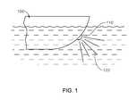
- FIG. 1illustrates a vessel having a transducer array disposed thereon in accordance with implementations of various techniques described herein.
- FIG. 2illustrates a block diagram of a sonar system which includes a sonar module in accordance with implementations of various techniques described herein.
- FIG. 3illustrates a flow diagram of a method for generating a depth display in accordance with implementations of various techniques described herein.
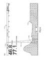
- FIG. 4illustrates a depth display in accordance with implementations of various techniques described herein.
- FIG. 5illustrates a depth display in accordance with implementations of various techniques described herein.
- FIG. 6illustrates an example schematic of a marine electronics device in accordance with implementations of various techniques described herein.
- a vessel configured to traverse a marine environmentmay use a sonar system disposed on and/or proximate to the vessel.
- the vesselmay be a surface water vehicle, a submersible water vehicle, or any other implementation known to those skilled in the art.
- the sonar systemin particular, may be used to acquire sonar data corresponding to an area of water proximate to the vessel, including areas to the side of, behind, below, and/or to the front of the vessel. Such sonar data may be used to identify objects in the area of water.
- a sonar systemmay include a sonar transducer array and one or more marine electronics devices.
- the transducer arraymay be composed of one or more transducer elements, where at least one transducer element is configured to produce one or more sound pressure signals (i.e., one or more sonar output signals).
- the transducer arraymay receive one or more transmit signals from a marine electronics device (as further described below), and, in response, produce the one or more sonar output signals.
- the transducer arraymay emit sonar output signals in a downward direction away from the vessel and into the area of water proximate to the vessel. Based on the transducer array's position with respect to the vessel and/or the arrangement of the transducer elements within the array itself, the sonar output signals may be emitted from one or more sides of the vessel, such as in front of the vessel. Properties of the sonar output signals generated by the transducer elements may be determined by an area and shape of the transducer elements, the sound wave frequency of the transducer elements, the sound velocity of the propagation medium (e.g., a body of water), and/or the like.
- Reflected sonar output signalsmay be received by one or more of the transducer elements of the array in the form of one or more sonar return signals.
- a sonar return signalmay represent an echo return that has reflected from a surface of an object in the area of water proximate to the vessel.
- an objectmay be a point on an underwater floor, a portion of a fish, a piece of debris, and/or any other waterborne object known to those skilled in the art.
- the transducer arraymay convert the sonar return signals into sonar data to be sent to the one or more marine electronics devices for processing (as further described below).
- the sonar datamay be in form of electrical signals (e.g., analog or digital signals) that are representative of the sonar return signals.
- the transducer arraymay be positioned at one or more locations that are on and/or proximate to the vessel, such as in one or more housings that are flexibly mounted to a hull of the vessel.
- the transducer arraymay be mounted to the hull of the vessel such that the array is submerged in the water proximate to the vessel.
- FIG. 1illustrates a vessel 100 having a transducer array 110 disposed thereon in accordance with implementations of various techniques described herein.
- the transducer array 110may be coupled to a hull of the vessel 100 , such that the transducer array 110 may be configured to downwardly emit one or more sonar output signals 120 in an area of water in front of the vessel 100 .
- the transducer array 110may also be positioned to acquire sonar data from this area of water (i.e., in the direction of travel of the vessel 100 ). This sonar data may then be sent to one or more marine electronics devices (not shown) for processing, such that one or more objects in the water in front of the vessel 100 may be identified, as further described below.
- one or more transducer elements of a transducer arraymay be arranged in a manner that is conducive to interferometry, as is known to those skilled in the art.
- the transducer elementsmay be spaced apart from one another within the transducer array at one or more known distances. As further described below, and as known to those skilled in the art, these known distances may be used to determine a phase of each sonar return signal received by each transducer element, which in turn may be used to determine a location of an object with respect to the vessel within the marine environment.
- the transducer arraymay transmit sonar data that is representative of the sonar return signals to one or more marine electronics devices.
- the one or more marine electronics devicesmay be configured to process the sonar data, as further described below.
- the one or more marine electronics devicesmay include a sonar module (e.g., a fish finder sonar module), a multi-function display (MFD) device, a smart phone, and/or any other implementation used for processing sonar data known to those skilled in the art.
- the sonar modulemay receive the sonar data from the transducer array, and then conduct one or more processing steps on the sonar data before transmitting the sonar data to another device, such as an MFD device, for display.
- the transducer array and the one or more marine electronics devicesmay be positioned at one or more locations on and/or proximate to a vessel.
- the one or more marine electronics devicesmay be configured to process the sonar data received from a transducer array.
- the marine electronics devicesmay perform such processing to determine locations of one or more objects with respect to the vessel within the marine environment, which can be used to generate a number of different images that portray information regarding the marine environment.
- the marine electronics devicesmay perform interferometric processing on the sonar data, as is known to those skilled in the art.
- FIG. 2illustrates a block diagram of a sonar system 200 which includes a sonar module 210 in accordance with implementations of various techniques described herein.
- the sonar system 200may include various components, which may include means embodied in hardware and/or software configured to perform one or more corresponding functions.
- the sonar system 200may include a transducer array 220 , a display element 230 , and a user interface 240 .
- the sonar module 210may include a transceiver 212 , a sonar signal processor 214 , and a network hub 216 .
- One or more other components and/or peripheral devices known to those skilled in the artmay be included in the sonar system 200 .
- the transducer array 220may transmit sonar data to the sonar module 210 for further processing.
- the transceiver 212may receive the sonar data from the transducer array 220 , and then transmit the received sonar data to the sonar signal processor 214 to carry out the processing.
- the sonar signal processor 214may determine locations of one or more objects with respect to the vessel within the marine environment, and then render a number of different images that portray information regarding the marine environment. Using the network hub 216 , those images may be transmitted to the display element 230 for display to a user.
- Similar components of the sonar module 210may be used in other marine electronics devices, such as in a multi-function display (MFD) device, a smart phone, and/or the like. Further implementations of the sonar system 200 and the sonar module 210 are discussed in greater detail below.
- MFDmulti-function display
- an operator of a vesselmay use sonar data to assist with the navigation of a vessel in a marine environment (i.e., an area of water).
- the sonar datawhen analyzed by one or more marine electronics devices, may be used to determine locations of objects within the marine environment, which, in turn, may be used to determine depths of an underwater floor, detect the presence of fish or other waterborne objects, and/or the like.
- a transducer array of a sonar systemmay be used to acquire sonar data corresponding to an area of water approximate to a vessel.
- This sonar datamay be analyzed by one or more marine electronics devices of the sonar system, such that objects in the water near the vessel may be identified.
- a depth displaymay be generated based on the analyzed sonar data.
- a depth displaymay be defined as a visualization of the depths of an underwater floor of a marine environment proximate to a vessel.
- FIG. 3illustrates a flow diagram of a method 300 for generating a depth display in accordance with implementations of various techniques described herein.
- method 300may be performed by a marine electronics device, such as a sonar module, an MFD device, a smart phone, and/or the like.
- the marine electronics devicemay be positioned on and/or proximate to a vessel, and may be part of a sonar system.
- method 300indicates a particular order of execution of operations, in some implementations, certain portions of the operations might be executed in a different order. Further, in some implementations, additional operations or steps may be added to the method 300 . Likewise, some operations or steps may be omitted.
- the marine electronics devicemay receive sonar data from a transducer array disposed on and/or proximate to the vessel.
- the transducer arraymay be similar to those described above.
- the transducer arraymay emit sonar output signals in a downward direction away from the vessel and into a marine environment proximate to the vessel (e.g., in front of the vessel). In return, the transducer array may receive sonar return signals that have reflected off of one or more objects in the marine environment. As noted above, an object may be a point on an underwater floor, a portion of a fish, a piece of debris, and/or any other waterborne object known to those skilled in the art. The transducer array may convert the sonar return signals into sonar data, which may then be sent to the marine electronics device.
- the marine electronics devicemay analyze the sonar data received from the transducer array.
- the marine electronics devicemay analyze the sonar data to determine locations of the one or more objects within the marine environment.
- the marine electronics devicemay perform interferometric processing on the sonar data, as is known to those skilled in the art.
- Interferometric processing of sonar datamay refer to processing which uses a phase measurement of a sonar return signal at each transducer element to determine an angle of arrival of the sonar return signal.
- the angle of arrivalmay refer to the angle that the sonar return signal makes with the transducer array.
- the transducer elementsmay be spaced apart from one another within the transducer array at particular distances.
- the marine electronics devicemay measure a phase at each of the spaced transducer elements using one or more techniques known to those skilled in the art. The differences between the phase measurements at each of the transducer elements may then be used to calculate the angle of arrival of the sonar return signal. In particular, the angle of arrival may be determined based on the spacing between the transducer elements within the transducer array, the phase differences of the sonar return signal, and/or the wavelength of the sonar return signal using one or more techniques known to those skilled in the art.
- the marine electronics devicemay determine a range for each sonar return signal of the sonar data.
- the rangemay be a distance determined based on the two-way travel time of the sonar return signal (e.g., the difference in time from when a sonar output signal is produced by the transducer array and when the sonar return signal is received by the transducer array).
- the amplitude of the sonar return signalmay be determined by the marine electronics device.
- the marine electronics devicemay then use the angle of arrival and the range of the sonar return signal to determine a location of the object proximate to the vessel from which the sonar return signal is reflected.
- the amplitude of the sonar return signalmay be used to determine the presence of and/or the type of the object.
- the marine electronics devicemay determine the object's location with respect to the transducer array or the vessel itself.
- the marine electronics devicemay repeat the above processing for each sonar return signal of the sonar data in order to determine a location for each object in the marine environment from which each sonar return signal is reflected.
- the marine electronics devicemay also analyze the sonar data based on an offset angle of the transducer array.
- the transducer arraymay be positioned at a specific angle (i.e., the offset angle) with respect to the vessel. In such an implementation, the marine electronics device may compensate for the offset angle when determining the locations of the objects in the marine environment.
- the marine electronics devicemay generate point cloud data based on the analyzed sonar data.
- the locations of the objectsmay be plotted with respect to the vessel using a Cartesian plot (i.e., an x-y plot) of the marine environment proximate to the vessel.
- a Cartesian ploti.e., an x-y plot
- a horizontal axisi.e., the x-axis
- a vertical axisi.e., the y-axis
- the marine electronics devicemay convert each location of the objects (as determined at block 320 ) into respective Cartesian points (i.e. x-y coordinates) that can be plotted with respect to the vessel.
- the locationsmay be converted into the respective x-y coordinates using any formula known to those skilled in the art.
- the generated point cloud datarepresents the collection of these converted Cartesian points for the determined locations.
- the converted Cartesian pointsmay appear as one or more scattered groups of points in the shape of a cloud.
- the marine electronics devicemay use a display element (e.g., the display element 230 of FIG. 2 ) to display the Cartesian plot of the marine environment with the plotted Cartesian points (i.e., the point cloud data).
- the marine electronics devicemay generate a depth display based on the point cloud data.
- a depth displaymay be defined as a visualization of the depths of an underwater floor of a marine environment proximate to a vessel.
- the depth displaymay be the same Cartesian plot as described above at block 320 , except at least a portion of the plotted point cloud data is replaced with a depth line.
- the depth linemay be a line in the Cartesian plot that illustrates the depths of the surface of the underwater floor in the marine environment proximate to the vessel.
- the depth linemay be generated using one or more image processing techniques.
- the image processing techniquesmay be used to identify trends in the point cloud data, where the trends may indicate the locations of the surface of the underwater floor. Displaying the depth line in place of a portion of the point cloud data may allow a user to more intuitively identify and/or understand the depths of the underwater floor.
- the marine electronics devicemay use an image processing technique to initially create one or more clusters of the plotted point cloud data.
- One or more clustering methodsmay be used to create the clusters, including a hierarchical-based clustering method, a centroid-based clustering method (e.g., k-means clustering), a distribution-based clustering method, a density-based clustering method, and/or any other clustering method known to those skilled in the art.
- the marine electronics devicemay group the plotted Cartesian points into one or more clusters based on one or more rules.
- a first rulemay be that, to be assigned into any cluster, a Cartesian point should represent a sonar return signal having an amplitude greater than or equal to a predetermined threshold.
- a second rulemay be that points within a predetermined Cartesian distance of one another should be grouped together into the same cluster. In some implementations, both the first and the second rules should be followed when placing a plotted Cartesian point into a cluster.
- Such rulesmay be used to better identify Cartesian points corresponding to a surface of the underwater floor as opposed to waterborne objects, fish, and/or the like
- the marine electronics devicemay identify the largest cluster.
- the marine electronics devicemay divide the Cartesian plot of the depth display into multiple sectors, and the marine electronics device may identify the largest cluster in the sector that is farthest from vessel location along the y-axis.
- the marine electronics devicemay then identify one or more remaining clusters that are within a minimum Cartesian distance of the largest cluster.
- the clusters that are within the minimum Cartesian distanceare then connected to the largest cluster using a line.
- the linemay be formed by connecting outlines of the clusters, where each outline is formed along a top side of the cluster. Further, the marine electronics device may employ a smoothing process on the line connecting the clusters.
- the marine electronics devicemay continue identifying the remaining unconnected clusters that are within a minimum Cartesian distance of an already connected cluster. The marine electronics device may then connect these remaining clusters to those that are connected. The marine electronics device may repeat this process of identifying and connecting clusters for multiple iterations until no remaining unconnected clusters are within the minimum Cartesian distance described above.
- the line formed by connecting the clustersis the depth line.
- the depth linemay be displayed instead of the portion of the point cloud data that forms the connected clusters.
- no other point cloud datamay be displayed in conjunction with the depth line.
- the depth linemay be displayed in conjunction with the remaining portion of the point cloud data.
- the remaining portion of the point cloud datamay include Cartesian points not grouped into a cluster and/or Cartesian points of the unconnected clusters.
- the marine electronics devicemay use a display element (e.g., the display element 230 of FIG. 2 ) to display the depth display of the marine environment with the generated depth line.
- a display elemente.g., the display element 230 of FIG. 2
- the marine electronics devicemay use an image processing technique that employs pixel quantization, blurring, and thresholding.
- a quantization of the Cartesian points(as described above with respect to block 330 ) may be performed, such that various Cartesian points are combined into a pixel of the display element.
- the Cartesian pointsmay be combined based on the points' respective distances relative to the vessel and the amplitudes of their representative sonar return signals. Any quantization techniques known to those skilled in the art may be used.
- one or more blurring techniquesmay be used to generate a gradient.
- the one or more blurring techniquesmay include any known to those skilled in the art, including box filtering, median filtering, and Gaussian filtering.
- one or more thresholding algorithmsmay be used.
- the one or more thresholding algorithmsmay include any known to those skilled in the art, including Otsu's method.
- the one or more thresholding algorithmsmay also be based on the amplitudes of the sonar return signals. Using such algorithms, a bimodal image of the sonar data may be generated from the gradient, such that contours may be displayed in the image. Once the bimodal image has been created, further techniques may be used to generate the depth display with the depth line, such as by using a visibility check and/or ray tracing.
- the depth displaymay be two-dimensional (2D).
- the method 300 for generating a depth displaymay be performed in real-time or substantially near real-time.
- the marine electronics devicemay use a speed of the vessel when generating the depth display. The speed of the vessel may be calculated by or may be supplied to the marine electronics device.
- the marine electronics devicemay increase the aggressiveness of filtering of the sonar data in response to high speeds traveled by the vessel when the sonar data was captured.
- method 300may be performed by multiple marine electronics devices.
- method 300may be performed by a sonar module in conjunction with another marine electronics device, such as an MFD.
- FIGS. 4-5illustrate examples of depth displays in accordance with implementations as described above.
- FIG. 4illustrates a depth display 400 in accordance with implementations of various techniques described herein.
- the depth display 400may be in the form of a Cartesian plot, in which locations of the one or more objects in front of a vessel may be plotted with respect to the vessel (i.e., point cloud data). It should be noted that other implementations of the depth display 400 may include Cartesian plots which illustrate objects to the side of and/or behind the vessel.
- a horizontal axis 410(i.e., the x-axis) may be used to display a range of distances in front of or ahead of the vessel, and a vertical axis 420 (i.e., the y-axis) may be used to display a scale of depths of the marine environment below the vessel.
- the position of the vessel in the marine environmentmay be represented at the point 440 where the x-axis and the y-axis intersect.
- the portion of the depth display 400 that is to the right of the point 440may represent the marine environment generally in front of the vessel. Accordingly, the range of distances along the horizontal axis 410 may increase in value in a rightward direction. Further, the scale of depths along the vertical axis 420 may increase in value in a downward direction.
- the depth display 400may also include a depth line 440 plotted in the depth display 400 .
- the depth line 440may be generated using point cloud data of the marine environment generally in front of the vessel using method 300 as described above. As is also noted above, the depth line 440 may be displayed instead of the portion of the point cloud data that forms the connected clusters of plotted points.
- the depth display 400 as shown by a display elementmay include a cursor that is movable via user input to a marine electronics device and/or a user interface.
- the depth display 400may visualize the range and depth values (i.e., x-y coordinates) of the cursor within the depth display, such as by displaying the values near the cursor.
- FIG. 5illustrates a depth display 500 in accordance with implementations of various techniques described herein.
- the depth display 500may include a horizontal axis 510 , a vertical axis 520 , a point 530 , and a depth line 540 .
- the depth display 500 and its componentsmay be similar to the depth display 500 and its components as described above with respect to FIG. 4 .
- point cloud data 550may be displayed in conjunction with the depth line 540 .
- the point cloud data 550may include Cartesian points not grouped into a cluster and/or Cartesian points of unconnected clusters. Including such point cloud data in the depth display may allow the operator of the vessel to identify various waterborne objects in the marine environment other than the surface of the underwater floor.
- the displayed point cloud data 550may represent the locations of a portion of a fish, a piece of debris, and/or any other waterborne object known to those skilled in the art.
- the portion of the depth display 400 below the depth line 440may be filled in with one or more colors. Such a filling-in of color may provide a visual contrast of the underwater floor when compared with the rest of the marine environment in the depth display 400 , thereby further assisting the operator of the vessel with identifying and/or understanding the depths of the underwater floor.
- the marine electronics devicemay use auto-ranging to determine the amount of area of the marine environment that is shown in the depth display 400 .
- the amount of area of the marine environment shown in the depth display 400may be based on the range of distances shown along the horizontal axis 410 and the scale of depths shown along the vertical axis 420 .
- the scale of depths shown along the vertical axis 420may be based on a depth value 450 of the depth line 440 (i.e., the underwater floor) directly below the point 440 (i.e., the vessel).
- a maximum depth value shown on the vertical axis 420may be equal to a sum of the depth value 450 and a predetermined constant value (e.g., 10 feet).
- the range of distances shown along the horizontal axis 410 and to the right of the point 440may be determined based on the vertical axis 420 .
- a maximum distance value shown on the horizontal axis 410may be equal to the maximum depth value shown on the vertical axis 420 multiplied by a predetermined multiplier.
- the depth displaymay be generated in real-time or substantially near real-time.
- the depth displaymay be generated as a vessel travels in a marine environment.
- the depth displaymay be stored in memory as the vessel travels in the marine environment, such that the depth display is continuously updated and displayed based on real-time or substantially near real-time sonar data.
- the depth displaymay be scrollable such that a history of the depth display may be viewed.
- the previously generated (i.e., stored) iterations of the depth display 400may be displayed to the left of the point 440 .
- a user inputmay be provided to indicate to the marine electronics device to more fully display these previously generated iterations. For example, a rightward swipe gesture on a touch screen showing the depth display 400 may result in the displaying of the previously generated iterations of the depth display 400 .
- the marine electronics devicemay display the depth line 440 in the previously generated iterations and the depth line 440 generated based on real-time or substantially near real-time sonar data as being connected.
- implementations relating to a depth display using sonar datamay help an operator of a vessel to identify and/or understand the depths of the underwater floor proximate to the vessel.
- the depth line of the depth displaymay assist the operator with identifying contours of the underwater floor, including dangerously low depths that may lie ahead.
- the transducer array 220 and/or sonar module 210may be positioned within a housing.
- the housingmay include a recessed portion defining a containment volume for holding the transducer elements.
- the housing(and in particular the containment volume portion of the housing) may have a gradual, rounded or otherwise streamlined profile to permit laminar flow of water over the housing.
- an insulated cablemay provide a conduit for wiring to couple each of the transducer elements to the sonar module 210 .
- any of a number of configurations of transducer elements and transducer arraysmay be provided within the housing.
- a transducer elementmay largely determine the type of beam that is formed when that transducer element transmits a sonar pulse (e.g., a circular transducer element emits a cone-shaped beam, a linear/rectangular transducer element emits a fan-shaped beam, etc.).
- a transducer elementmay comprise one or more transducer elements positioned to form one transducer element.
- a rectangular transducer elementmay comprise two or more rectangular transducer elements aligned with each other so as to be collinear.
- three transducer elements aligned in a collinear fashionmay define one rectangular transducer element.
- transducer elementsmay comprise different types of materials that cause different sonar pulse properties upon transmission.
- the type of materialmay determine the strength of the sonar pulse.
- the type of materialmay affect the sonar returns received by the transducer element.
- implementations described hereinare not meant to limit the shape or material of the transducer elements.
- each of the transducer elementsmay be a rectangular transducer element.
- each of the transducer elementsmay be substantially rectangular in shape and made from a piezoelectric material such as a piezoelectric ceramic material, as is well known in the art.
- the transducer elementsmay be configured to transmit and/or receive a fan-shaped beam (e.g., 15° by 90°, though any fan shaped beam is contemplated).
- any of the transducer elements described hereinmay be configured to transmit and receive sonar pulses (e.g., transmit/receive transducer elements). While the transducer elements may be described herein as transmit/receive transducer elements, in some implementations, the transducer elements may be configured as receive-only transducer elements, or in other cases, transmit-only transducer elements.
- each transducer elementmay be configured to operate at any frequency, including operation over an array of frequencies.
- the sonar module 210may include a variable frequency selector, to enable an operator to select a particular frequency of choice for the current operating conditions.
- the active element in a given transducermay comprise at least one crystal. Wires may be soldered to coatings so that the crystal can be attached to a cable which transfers the electrical energy from the transmitter to the crystal.
- the crystalmay move, creating sound waves at that frequency.
- the shape of the crystalmay determine both its resonant frequency and shape and angle of the emanated sound beam.
- Frequencies used by sonar devicesvary, but may range from 50 KHz to over 900 KHz depending on application. Some sonar systems may vary the frequency within each sonar pulse using “chirp” technology. These frequencies may be in the ultrasonic sound spectrum and thus inaudible to humans.
- widths of various beamsare described herein, the widths being referred may not correspond to actual edges defining limits to where energy is placed in the water.
- beam patterns and projections of beam patternsare generally described herein as having fixed and geometrically shaped and sharply defined boundaries, those boundaries merely correspond to the ⁇ 3 dB (or half power) points for the transmitted beams. In other words, energy measured outside of the boundaries described is less than half of the energy transmitted, but this sound energy is present nonetheless. Thus, some of the boundaries described are merely theoretical half power point boundaries.
- the display element 230 , the user interface 240 , and/or the sonar module 210may be configured to communicate with one another via a network 218 and/or the network hub 216 .
- the network 218 and/or the network hub 216may be implemented using any wired and/or wireless technology known to those skilled in the art, including, but not limited to, Ethernet, the National Marine Electronics Association (NMEA) framework, Bluetooth, Wi-Fi, LAN, WLAN, cellular, and/or any other network implementation.
- NMEANational Marine Electronics Association
- the display element 230 , the user interface 240 , and/or the sonar module 210may be configured to communicate with one another directly without the use of the network 218 or the network hub 216 .
- the display element 230 , the sonar module 210 , and/or the user interface 240may be part of a single device, such that at least two of those components are located in a single housing.
- the network hub 216may include one or more interface ports to allow components, such as the display element 230 or the user interface 240 , to communicate with the network 218 .
- the network hub 216may be configured to allow for plug-and-play communication with the display element 230 and/or the user interface 240 .
- the display element 230may be configured to display images, where it may receive processed sonar data from the sonar signal processor 214 and render the data into one or more windows on the display element 230 .
- the display element 230may include a liquid crystal display (LCD) screen, a touch screen display, or any other implementation known to those skilled in the art.
- the display element 230may include two or more displays.
- a usermay interact with the sonar system 200 through the user interface 240 .
- the user interface 240may include, for example, a keyboard, keypad, function keys, mouse, scrolling device, input/output ports, touch screen, or any other user interface known to those skilled in the art.
- the user interface 240may be integrated into the display element 230 .
- the sonar signal processor 214may be any device or circuitry operating in accordance with hardware and/or software which configures the device or circuitry to perform the corresponding functions of the sonar signal processor 214 as described herein.
- the sonar signal processor 214may include a processor, a processing element, a coprocessor, a controller, an application specific integrated circuit (ASIC), a field programmable gate array (FPGA), a hardware accelerator, or any other implementation known to those skilled in the art, where the sonar signal processor 214 is configured to execute various programmed operations or instructions stored in a memory device.
- the sonar signal processor 214may further include multiple compatible additional hardware and/or software items configured to: (i) implement signal processing or enhancement features to improve display characteristics, data, and/or images, (ii) collect or process additional data, such as time, temperature, global positioning system (GPS) information, and/or waypoint designations, or (iii) filter extraneous data to better analyze the collected data.
- the sonar signal processor 214may further implement notices and alarms, such as those determined or adjusted by a user, to reflect depth, presence of fish, and/or proximity of other watercraft.
- the sonar signal processor 214may store incoming data from the transducer array 220 , screen images for future playback, transfer and/or alter images with additional processing to implement zoom or lateral movement, or correlate data such as fish or bottom features to a GPS position or temperature.
- the sonar module 210may include standard elements and/or components, including memory (e.g., non-transitory computer-readable storage medium), at least one database, power, peripherals, and various other computing elements and/or components that may not be specifically shown in FIG. 2 .
- the user interface 240may be used to receive one or more preferences from a user of the display element 230 for managing or utilizing the sonar system 200 , including interfacing with the transducer array 220 . Further, the user may set up desired behavior of the sonar module 210 and/or transducer array 220 via user-selected preferences using the user interface 240 .
- the sonar module 210may be configured to transmit one or more transmit signals to the transducer array 220 , such that, in response, the transducer array 220 produces one or more sonar output signals.
- the transducer array 220produces one or more sonar output signals.
- Various elements and/or components of the system 200 that may be useful for the purpose of implementing method 300may be added, included, and/or interchanged, in manner as described herein.
- various types of dataincluding sonar data may be communicated, transmitted, and/or relayed between the sonar module 210 and the transducer 220 .
- the sonar module 210may interface and communicate with the transducer array 220 via wired and/or wireless connections known to those skilled in the art.
- the sonar module 210may include computer-executable instructions related to a storage handler or software module configured to automatically record the sonar data in memory (e.g., a database) upon receiving the sonar data from the transducer 220 .
- recording the sonar data generated by the transducer 220may include logging the sonar data generated by the transducer 220 and the geographical coordinate data (i.e., GPS data) associated with the transducer 220 .
- the storage handlermay be configured to automatically upload the sonar data and/or the GPS data to at least one database via a network, such as, e.g., a remote server database (e.g., a cloud based server) via a communication network (e.g., a cloud based network), including a wireless communication network.
- a networksuch as, e.g., a remote server database (e.g., a cloud based server) via a communication network (e.g., a cloud based network), including a wireless communication network.
- a data manager of the sonar module 210may include computer-executable instructions related to a display handler or software module configured to display images associated with the sonar data, e.g., to a user via the display element 230 .
- the display handlermay be configured to generate image data associated with the sonar data and further display images generated from the image data and sonar data to a user via a display.
- the display handlermay be configured to display images associated with a map to the user based on the sonar data and the geographical coordinate data (i.e., GPS data).
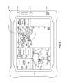
- FIG. 6illustrates an example schematic of a marine electronics device 600 in accordance with implementations of various techniques described herein.
- the marine electronics device 600may be in the form of an MFD device.
- the MFD device 600includes a screen 605 .
- the screen 605may be sensitive to touching by a finger.
- the screen 605may be sensitive to the body heat from the finger, a stylus, or responsive to a mouse.
- the marine electronics device 600may be attached to a NMEA bus or network.
- the MFD device 600may send or receive data to or from another device attached to the NMEA 2000 bus.
- the MFD device 600may transmits commands and receive data from a motor or a sensor using an NMEA 2000 bus.
- the MFD device 600may be capable of steering a vessel and controlling the speed of the vessel, i.e., autopilot.
- one or more waypointsmay be input to the marine electronics device 600 , and the MFD device 600 may steer a vessel to the one or more waypoints.
- the MFD device 600may transmit or receive NMEA 2000 compliant messages, messages in a proprietary format that do not interfere with NMEA 2000 compliant messages or devices, or messages in any other format.
- the device 600may display marine electronic data 615 .
- the marine electronic data types 615may include chart data, radar data, sonar data, steering data, dashboard data, navigation data, fishing data, engine data, and the like.
- the MFD device 600may also include a plurality of buttons 620 , which may be either physical buttons or virtual buttons, or a combination thereof.
- the MFD device 600may receive input through a screen 605 sensitive to touch or buttons 620 .
- a marine electronics devicemay be used to record and process sonar data.
- the marine electronics devicemay be operational with numerous general purpose or special purpose computing system environments or configurations.
- the marine electronics devicemay include any type of electrical and/or electronics device capable of processing data and information via a computing system.
- the marine electronics devicemay be a marine instrument, such that the marine electronics device may use the computing system to display and/or process the one or more types of marine electronics data.
- Implementations of various technologies described hereinmay be operational with numerous general purpose or special purpose computing system environments or configurations.
- Examples of well-known computing systems, environments, and/or configurations that may be suitable for use with the various technologies described hereininclude, but are not limited to, personal computers, server computers, hand-held or laptop devices, multiprocessor systems, microprocessor-based systems, set top boxes, programmable consumer electronics, network PCs, minicomputers, mainframe computers, smart phones, tablets, wearable computers, cloud computing systems, virtual computers, marine electronics devices, and the like.
- program modulesinclude routines, programs, objects, components, data structures, etc. that performs particular tasks or implement particular abstract data types. Further, each program module may be implemented in its own way, and all need not be implemented the same way. While program modules may all execute on a single computing system, it should be appreciated that, in some implementations, program modules may be implemented on separate computing systems or devices adapted to communicate with one another. A program module may also be some combination of hardware and software where particular tasks performed by the program module may be done either through hardware, software, or both.
- the various technologies described hereinmay be implemented in the context of marine electronics, such as devices found in marine vessels and/or navigation systems.
- Ship instruments and equipmentmay be connected to the computing systems described herein for executing one or more navigation technologies.
- the computing systemsmay be configured to operate using various radio frequency technologies and implementations, such as sonar, radar, GPS, and like technologies.
- program modulesmay be located in both local and remote computer storage media including memory storage devices.
- first, second, etc.may be used herein to describe various elements, these elements should not be limited by these terms. These terms are only used to distinguish one element from another.
- a first object or stepcould be termed a second object or step, and, similarly, a second object or step could be termed a first object or step, without departing from the scope of the invention.
- the first object or step, and the second object or stepare both objects or steps, respectively, but they are not to be considered the same object or step.
- the term “if”may be construed to mean “when” or “upon” or “in response to determining” or “in response to detecting,” depending on the context.
- the phrase “if it is determined” or “if [a stated condition or event] is detected”may be construed to mean “upon determining” or “in response to determining” or “upon detecting [the stated condition or event]” or “in response to detecting [the stated condition or event],” depending on the context.
Landscapes
- Engineering & Computer Science (AREA)
- Physics & Mathematics (AREA)
- Radar, Positioning & Navigation (AREA)
- Remote Sensing (AREA)
- General Physics & Mathematics (AREA)
- Computer Networks & Wireless Communication (AREA)
- Theoretical Computer Science (AREA)
- Acoustics & Sound (AREA)
- Computer Vision & Pattern Recognition (AREA)
- Software Systems (AREA)
- Life Sciences & Earth Sciences (AREA)
- Hydrology & Water Resources (AREA)
- Probability & Statistics with Applications (AREA)
- Multimedia (AREA)
- Geometry (AREA)
- Computer Graphics (AREA)
- Measurement Of Velocity Or Position Using Acoustic Or Ultrasonic Waves (AREA)
Abstract
Description
Claims (20)
Priority Applications (4)
| Application Number | Priority Date | Filing Date | Title |
|---|---|---|---|
| US14/798,148US9720084B2 (en) | 2014-07-14 | 2015-07-13 | Depth display using sonar data |
| AU2015291223AAU2015291223B2 (en) | 2014-07-14 | 2015-07-14 | Depth display using sonar data |
| EP15767579.4AEP3170019B1 (en) | 2014-07-14 | 2015-07-14 | Depth display using sonar data |
| PCT/IB2015/055301WO2016009336A1 (en) | 2014-07-14 | 2015-07-14 | Depth display using sonar data |
Applications Claiming Priority (2)
| Application Number | Priority Date | Filing Date | Title |
|---|---|---|---|
| US201462024416P | 2014-07-14 | 2014-07-14 | |
| US14/798,148US9720084B2 (en) | 2014-07-14 | 2015-07-13 | Depth display using sonar data |
Publications (2)
| Publication Number | Publication Date |
|---|---|
| US20160011310A1 US20160011310A1 (en) | 2016-01-14 |
| US9720084B2true US9720084B2 (en) | 2017-08-01 |
Family
ID=55067428
Family Applications (1)
| Application Number | Title | Priority Date | Filing Date |
|---|---|---|---|
| US14/798,148Active2035-07-20US9720084B2 (en) | 2014-07-14 | 2015-07-13 | Depth display using sonar data |
Country Status (4)
| Country | Link |
|---|---|
| US (1) | US9720084B2 (en) |
| EP (1) | EP3170019B1 (en) |
| AU (1) | AU2015291223B2 (en) |
| WO (1) | WO2016009336A1 (en) |
Cited By (2)
| Publication number | Priority date | Publication date | Assignee | Title |
|---|---|---|---|---|
| US11143758B2 (en) | 2017-10-13 | 2021-10-12 | Navico Holding As | Sonar transducer performance optimization |
| US12256059B2 (en) | 2023-05-09 | 2025-03-18 | T-Mobile Usa, Inc. | Stimulus-responsive depth-changing display |
Families Citing this family (10)
| Publication number | Priority date | Publication date | Assignee | Title |
|---|---|---|---|---|
| CN102866402B (en)* | 2012-08-22 | 2014-12-10 | 深圳市福锐达科技有限公司 | Wireless fidelity (WIFI)-based wireless hydrological regime detection system and method |
| US10094918B2 (en) | 2014-09-13 | 2018-10-09 | Navico Holding As | Alert zones for a marine environment |
| US11209543B2 (en) | 2015-01-15 | 2021-12-28 | Navico Holding As | Sonar transducer having electromagnetic shielding |
| US10597130B2 (en) | 2015-01-15 | 2020-03-24 | Navico Holding As | Trolling motor with a transducer array |
| US10503393B2 (en)* | 2015-03-06 | 2019-12-10 | FLIR Belgium BVBA | Touch screen sonar adjustment systems and methods |
| US10719077B2 (en) | 2016-10-13 | 2020-07-21 | Navico Holding As | Castable sonar devices and operations in a marine environment |
| JP7051625B2 (en)* | 2018-07-12 | 2022-04-11 | 古野電気株式会社 | Underwater detector and underwater detection method |
| EP3961252A1 (en) | 2020-08-28 | 2022-03-02 | Universiteit Antwerpen | An in-air sonar system and a method therefor |
| US12007512B2 (en)* | 2020-11-30 | 2024-06-11 | Navico, Inc. | Sonar display features |
| CN117991241B (en)* | 2024-01-19 | 2024-07-16 | 中国科学院声学研究所 | Target depth information extraction method and system based on modal wave number spectrum transformation |
Citations (88)
| Publication number | Priority date | Publication date | Assignee | Title |
|---|---|---|---|---|
| US3187704A (en) | 1961-03-14 | 1965-06-08 | Shell Oil Co | Ship control system |
| US3795893A (en) | 1971-07-06 | 1974-03-05 | Sperry Rand Corp | Doppler speed log |
| US3893076A (en) | 1973-10-18 | 1975-07-01 | Raytheon Co | Speed measurement system |
| US4312053A (en) | 1971-12-03 | 1982-01-19 | Subcom, Inc. | Range and depth detection system |
| US4829493A (en) | 1985-06-14 | 1989-05-09 | Techsonic Industries, Inc. | Sonar fish and bottom finder and display |
| US4879697A (en) | 1988-08-05 | 1989-11-07 | Lowrance Electronics, Inc. | Sonar fish finder apparatus providing split-screen display |
| US4939661A (en) | 1988-09-09 | 1990-07-03 | World Research Institute For Science And Technology | Apparatus for a video marine navigation plotter with electronic charting and methods for use therein |
| US5025423A (en) | 1989-12-21 | 1991-06-18 | At&T Bell Laboratories | Enhanced bottom sonar system |
| US5122990A (en) | 1991-02-01 | 1992-06-16 | Rowe-Deines Instruments Incorporated | Bottom tracking system |
| US5184330A (en) | 1991-06-25 | 1993-02-02 | Techsonic Industries, Inc. | Multi-beam sonar fish detection apparatus providing real-time three-dimensional wire-frame display representation |
| US5191341A (en) | 1987-12-01 | 1993-03-02 | Federation Francaise De Voile | System for sea navigation or traffic control/assistance |
| US5537380A (en) | 1995-07-14 | 1996-07-16 | Lowrance Electronics, Inc. | Sonar system having an interactive sonar viewing apparatus and method of configuring same |
| US5675552A (en) | 1995-10-02 | 1997-10-07 | Interphase Technologies, Inc. | Sonar apparatus having a steerable beam |
| US6185505B1 (en) | 1998-09-04 | 2001-02-06 | Lockheed Martin Corporation | Broad ocean bathymetric fix |
| US6201767B1 (en) | 1998-09-30 | 2001-03-13 | Airmar Technology Corporation | Adjustable in-hull transducer assembly |
| US6225984B1 (en) | 1998-05-01 | 2001-05-01 | Hitachi Micro Systems, Inc. | Remote computer interface |
| US6321158B1 (en) | 1994-06-24 | 2001-11-20 | Delorme Publishing Company | Integrated routing/mapping information |
| US20020035574A1 (en) | 2000-09-04 | 2002-03-21 | Jean-Baptiste Dumas | Apparatus and method for exporting data from a database to a data processing terminal |
| US6411283B1 (en) | 1999-05-20 | 2002-06-25 | Micron Technology, Inc. | Computer touch screen adapted to facilitate selection of features at edge of screen |
| US6418080B2 (en) | 2000-03-31 | 2002-07-09 | Furuno Electric Company, Limited | Underwater detection apparatus |
| US6421299B1 (en) | 2000-06-28 | 2002-07-16 | Techsonic Industries, Inc. | Single-transmit, dual-receive sonar |
| US20020093541A1 (en) | 1999-04-06 | 2002-07-18 | Rodica Schileru-Key | Graph-based visual navigation through spatial environments |
| US6761692B2 (en) | 2001-06-25 | 2004-07-13 | Eagle Ultrasound As | High frequency and multi frequency band ultrasound transducers based on ceramic films |
| US20040193364A1 (en) | 2000-09-18 | 2004-09-30 | Robert Chojnacki | Computing system with decryption functions and secure data product |
| US6816782B1 (en) | 2002-10-10 | 2004-11-09 | Garmin Ltd. | Apparatus, systems and methods for navigation data transfer between portable devices |
| US20050007880A1 (en) | 2003-06-02 | 2005-01-13 | Zimmerman Matthew Jason | Processing technique for forward looking sonar |
| US20050102101A1 (en) | 2001-12-11 | 2005-05-12 | Garmin Ltd., A Cayman Islands Corporation | System and method for calculating a navigation route based on non-contiguous cartographic map databases |
| US20050099887A1 (en)* | 2002-10-21 | 2005-05-12 | Farsounder, Inc | 3-D forward looking sonar with fixed frame of reference for navigation |
| US20060002235A1 (en) | 2003-07-19 | 2006-01-05 | Gareth Knowles | Pressure sensitive sensor for real-time reconfigurable sonar applications |
| US20060013066A1 (en) | 2004-07-19 | 2006-01-19 | Yasushi Nishimori | Ultrasonic transmitting/receiving apparatus and scanning sonar employing same |
| US7002579B2 (en) | 2001-05-09 | 2006-02-21 | Cadec Corporation | Split screen GPS and electronic tachograph |
| JP2006064770A (en) | 2004-08-24 | 2006-03-09 | Pentax Corp | Lens drive mechanism |
| US20060119585A1 (en) | 2004-12-07 | 2006-06-08 | Skinner David N | Remote control with touchpad and method |
| US7113449B2 (en)* | 2003-12-18 | 2006-09-26 | Fairbairn Scott R | Marine electronics with lure depth analyzer |
| US20060224940A1 (en) | 2005-04-04 | 2006-10-05 | Sam Lee | Icon bar display for video editing system |
| US7236426B2 (en) | 2004-09-08 | 2007-06-26 | Lowrance Electronics, Inc. | Integrated mapping and audio systems |
| US20070159922A1 (en)* | 2001-06-21 | 2007-07-12 | Zimmerman Matthew J | 3-D sonar system |
| US20070291589A1 (en) | 2004-08-10 | 2007-12-20 | Furuno Electric Co., Ltd. | Forward-looking sonar and underwater image display system |
| US20080008042A1 (en) | 2006-07-07 | 2008-01-10 | Svein Arne Frivik | Depth sounding by acoustic pingers in a seismic spread |
| US20080080317A1 (en) | 2006-10-02 | 2008-04-03 | Furuno Electric Company, Ltd. | Fishfinder |
| US20080126935A1 (en) | 2006-11-08 | 2008-05-29 | Ross James Blomgren | Audio Visual Entertainment System and Method of Operation |
| US20080192575A1 (en) | 2007-02-14 | 2008-08-14 | Navico Inc. | Method, Apparatus and Computer Program Product for Providing a Sonar History |
| US20080204424A1 (en) | 2007-02-22 | 2008-08-28 | Samsung Electronics Co., Ltd. | Screen display method for mobile terminal |
| US7430461B1 (en) | 2004-10-18 | 2008-09-30 | Navico International Limited | Networking method and network for marine navigation devices |
| US20090099871A1 (en) | 2005-08-09 | 2009-04-16 | Gopal Gadodia | Workflow Oriented Multiscreen Healthcare Information Management System |
| US7542376B1 (en) | 2006-07-27 | 2009-06-02 | Blueview Technologies, Inc. | Vessel-mountable sonar systems |
| US20090147623A1 (en) | 2004-08-02 | 2009-06-11 | Johnson Outdoors Inc. | Side scan sonar imaging system with associated GPS data |
| US20090179789A1 (en) | 2008-01-14 | 2009-07-16 | Apple Inc. | Electronic device control based on user gestures applied to a media headset |
| US20090249247A1 (en) | 2008-01-30 | 2009-10-01 | Erick Tseng | Notification of Mobile Device Events |
| US20090287409A1 (en) | 2006-04-12 | 2009-11-19 | Craig Summers | Navigational planning and display method for the sailor's dilemma when heading upwind |
| US20100145601A1 (en) | 2008-12-04 | 2010-06-10 | Verizon Data Services Llc | Navigation based on user-defined points and paths |
| US20100142324A1 (en) | 2008-12-08 | 2010-06-10 | Teledyne Rd Instruments, Inc. | Multi-state beamforming array |
| US20100157736A1 (en) | 2007-06-15 | 2010-06-24 | University Of Limerick | Method and apparatus for determining the topography of a seafloor and a vessel comprising the apparatus |
| US20100199225A1 (en) | 2009-01-30 | 2010-08-05 | Navico Holdings As | Method, apparatus and computer program product for synchronizing cursor events |
| US20100226203A1 (en) | 2007-11-02 | 2010-09-09 | David Buttle | System and method for underwater seismic data acquisition |
| US20100250122A1 (en) | 2009-03-26 | 2010-09-30 | Kubota Yugo | Sail assist device |
| US7812667B2 (en) | 2008-03-10 | 2010-10-12 | Qualcomm Incorporated | System and method of enabling a signal processing device in a relatively fast manner to process a low duty cycle signal |
| US20100302908A1 (en) | 2009-05-27 | 2010-12-02 | Strong Brandon S | System and method for determining wave characteristics from a moving platform |
| US7870496B1 (en) | 2009-01-29 | 2011-01-11 | Jahanzeb Ahmed Sherwani | System using touchscreen user interface of a mobile device to remotely control a host computer |
| US20110013484A1 (en) | 2009-07-14 | 2011-01-20 | Navico, Inc. | Linear and circular downscan imaging sonar |
| US20110013485A1 (en) | 2009-07-14 | 2011-01-20 | Navico, Inc. | Downscan imaging sonar |
| US20110019887A1 (en) | 2005-07-01 | 2011-01-27 | Hologic, Inc. | Displaying And Navigating Computer-Aided Detection Results On A Review Workstation |
| US20110025720A1 (en) | 2009-07-28 | 2011-02-03 | Samsung Electronics Co., Ltd. | Data scroll method and apparatus |
| US7890867B1 (en) | 2006-06-07 | 2011-02-15 | Adobe Systems Incorporated | Video editing functions displayed on or near video sequences |
| US20110054784A1 (en) | 2009-09-03 | 2011-03-03 | ProMap Technologies, Inc. | Shallow water highlight method and display systems |
| US20110154183A1 (en) | 2009-12-04 | 2011-06-23 | Google Inc. | Presenting real-time search results |
| US8019532B2 (en) | 2005-03-07 | 2011-09-13 | Telecommunication Systems, Inc. | Method and system for identifying and defining geofences |
| US8063540B2 (en) | 2004-03-08 | 2011-11-22 | Emantec As | High frequency ultrasound transducers based on ceramic films |
| US20120001773A1 (en) | 2009-07-26 | 2012-01-05 | Peter Lyons | Avionics device, systems and methods of display |
| US20120011437A1 (en) | 2010-07-08 | 2012-01-12 | James Bryan J | Device, Method, and Graphical User Interface for User Interface Screen Navigation |
| US20120014220A1 (en) | 2008-08-07 | 2012-01-19 | Depasqua Louis | Sonar navigation system and method |
| US20120069712A1 (en) | 2010-09-17 | 2012-03-22 | Vivid Engineering, Inc. | Ultrasonic distance measurement controller |
| US20120163126A1 (en) | 2010-12-22 | 2012-06-28 | Ewan Fraser Campbell | Ultrasonic/acoustic transducer |
| US20120185801A1 (en) | 2011-01-18 | 2012-07-19 | Savant Systems, Llc | Remote control interface providing head-up operation and visual feedback when interacting with an on screen display |
| US20120281507A1 (en) | 2011-05-06 | 2012-11-08 | Rikoski Richard J | Systems and methods for overpinging synthetic aperture sonar transmitters |
| US20130007665A1 (en) | 2011-06-05 | 2013-01-03 | Apple Inc. | Systems and methods for displaying notifications received from multiple applications |
| EP2602639A1 (en) | 2011-12-07 | 2013-06-12 | Navico, Inc. | Sonar rendering system and associated method |
| US20130208568A1 (en) | 2012-02-10 | 2013-08-15 | Navico, Inc. | Sonar Assembly for Reduced Interference |
| US20130242700A1 (en) | 2012-03-15 | 2013-09-19 | Echopilot Marine Electronics Limited | Sonar apparatus |
| US20140010048A1 (en) | 2012-07-06 | 2014-01-09 | Navico Holding As | Sonar System Using Frequency Bursts |
| US20140010049A1 (en) | 2012-07-06 | 2014-01-09 | Navico Holding As | Sonar Module Using Multiple Receiving Elements |
| US20140210256A1 (en) | 2012-07-02 | 2014-07-31 | Kohler Co. | Power generation system with anticipatory operation |
| US20140216325A1 (en) | 2013-02-07 | 2014-08-07 | Kevin Richard Hardy | Undersea Free Vehicle and Components |
| US20140269163A1 (en) | 2013-03-15 | 2014-09-18 | Navico, Inc. | Sonar Multi-Function Display With Built-In Chirp Processing |
| US20140269192A1 (en) | 2013-03-14 | 2014-09-18 | Navico Holding As | Sonar transducer assembly |
| US8949096B2 (en) | 2012-05-09 | 2015-02-03 | The United States Of America, As Represented By The Secretary Of The Navy | Three-dimensional tracer dispersion model |
| US20150085602A1 (en) | 2012-07-18 | 2015-03-26 | Reelsonar, Inc. | System and method for finding fish using a sonar device and a remote computing system |
| US20150097838A1 (en)* | 2013-10-09 | 2015-04-09 | Navico Holding As | Sonar depth display |
- 2015
- 2015-07-13USUS14/798,148patent/US9720084B2/enactiveActive
- 2015-07-14EPEP15767579.4Apatent/EP3170019B1/enactiveActive
- 2015-07-14AUAU2015291223Apatent/AU2015291223B2/enactiveActive
- 2015-07-14WOPCT/IB2015/055301patent/WO2016009336A1/enactiveApplication Filing
Patent Citations (100)
| Publication number | Priority date | Publication date | Assignee | Title |
|---|---|---|---|---|
| US3187704A (en) | 1961-03-14 | 1965-06-08 | Shell Oil Co | Ship control system |
| US3795893A (en) | 1971-07-06 | 1974-03-05 | Sperry Rand Corp | Doppler speed log |
| US4312053A (en) | 1971-12-03 | 1982-01-19 | Subcom, Inc. | Range and depth detection system |
| US3893076A (en) | 1973-10-18 | 1975-07-01 | Raytheon Co | Speed measurement system |
| US4829493A (en) | 1985-06-14 | 1989-05-09 | Techsonic Industries, Inc. | Sonar fish and bottom finder and display |
| US5191341A (en) | 1987-12-01 | 1993-03-02 | Federation Francaise De Voile | System for sea navigation or traffic control/assistance |
| US4879697A (en) | 1988-08-05 | 1989-11-07 | Lowrance Electronics, Inc. | Sonar fish finder apparatus providing split-screen display |
| US4939661A (en) | 1988-09-09 | 1990-07-03 | World Research Institute For Science And Technology | Apparatus for a video marine navigation plotter with electronic charting and methods for use therein |
| US5025423A (en) | 1989-12-21 | 1991-06-18 | At&T Bell Laboratories | Enhanced bottom sonar system |
| US5122990A (en) | 1991-02-01 | 1992-06-16 | Rowe-Deines Instruments Incorporated | Bottom tracking system |
| US5184330A (en) | 1991-06-25 | 1993-02-02 | Techsonic Industries, Inc. | Multi-beam sonar fish detection apparatus providing real-time three-dimensional wire-frame display representation |
| US6321158B1 (en) | 1994-06-24 | 2001-11-20 | Delorme Publishing Company | Integrated routing/mapping information |
| US5537380A (en) | 1995-07-14 | 1996-07-16 | Lowrance Electronics, Inc. | Sonar system having an interactive sonar viewing apparatus and method of configuring same |
| US5675552A (en) | 1995-10-02 | 1997-10-07 | Interphase Technologies, Inc. | Sonar apparatus having a steerable beam |
| US6225984B1 (en) | 1998-05-01 | 2001-05-01 | Hitachi Micro Systems, Inc. | Remote computer interface |
| US6185505B1 (en) | 1998-09-04 | 2001-02-06 | Lockheed Martin Corporation | Broad ocean bathymetric fix |
| US6201767B1 (en) | 1998-09-30 | 2001-03-13 | Airmar Technology Corporation | Adjustable in-hull transducer assembly |
| US20020093541A1 (en) | 1999-04-06 | 2002-07-18 | Rodica Schileru-Key | Graph-based visual navigation through spatial environments |
| US6411283B1 (en) | 1999-05-20 | 2002-06-25 | Micron Technology, Inc. | Computer touch screen adapted to facilitate selection of features at edge of screen |
| US6418080B2 (en) | 2000-03-31 | 2002-07-09 | Furuno Electric Company, Limited | Underwater detection apparatus |
| US6421299B1 (en) | 2000-06-28 | 2002-07-16 | Techsonic Industries, Inc. | Single-transmit, dual-receive sonar |
| US20020035574A1 (en) | 2000-09-04 | 2002-03-21 | Jean-Baptiste Dumas | Apparatus and method for exporting data from a database to a data processing terminal |
| US20040193364A1 (en) | 2000-09-18 | 2004-09-30 | Robert Chojnacki | Computing system with decryption functions and secure data product |
| US7002579B2 (en) | 2001-05-09 | 2006-02-21 | Cadec Corporation | Split screen GPS and electronic tachograph |
| US20070159922A1 (en)* | 2001-06-21 | 2007-07-12 | Zimmerman Matthew J | 3-D sonar system |
| US6761692B2 (en) | 2001-06-25 | 2004-07-13 | Eagle Ultrasound As | High frequency and multi frequency band ultrasound transducers based on ceramic films |
| US20050102101A1 (en) | 2001-12-11 | 2005-05-12 | Garmin Ltd., A Cayman Islands Corporation | System and method for calculating a navigation route based on non-contiguous cartographic map databases |
| US6816782B1 (en) | 2002-10-10 | 2004-11-09 | Garmin Ltd. | Apparatus, systems and methods for navigation data transfer between portable devices |
| US20050099887A1 (en)* | 2002-10-21 | 2005-05-12 | Farsounder, Inc | 3-D forward looking sonar with fixed frame of reference for navigation |
| US7035166B2 (en) | 2002-10-21 | 2006-04-25 | Farsounder, Inc. | 3-D forward looking sonar with fixed frame of reference for navigation |
| US20050007880A1 (en) | 2003-06-02 | 2005-01-13 | Zimmerman Matthew Jason | Processing technique for forward looking sonar |
| US20060002235A1 (en) | 2003-07-19 | 2006-01-05 | Gareth Knowles | Pressure sensitive sensor for real-time reconfigurable sonar applications |
| US7113449B2 (en)* | 2003-12-18 | 2006-09-26 | Fairbairn Scott R | Marine electronics with lure depth analyzer |
| US8063540B2 (en) | 2004-03-08 | 2011-11-22 | Emantec As | High frequency ultrasound transducers based on ceramic films |
| US20060013066A1 (en) | 2004-07-19 | 2006-01-19 | Yasushi Nishimori | Ultrasonic transmitting/receiving apparatus and scanning sonar employing same |
| US7710825B2 (en) | 2004-08-02 | 2010-05-04 | Johnson Outdoors Inc. | Side scan sonar imaging system with boat position on display |
| US20100080082A1 (en) | 2004-08-02 | 2010-04-01 | Johnson Outdoors Inc. | Side scan sonar imaging system |
| US7755974B2 (en) | 2004-08-02 | 2010-07-13 | Johnson Outdoors Inc. | Side scan sonar imaging system with enhancement |
| US20090147623A1 (en) | 2004-08-02 | 2009-06-11 | Johnson Outdoors Inc. | Side scan sonar imaging system with associated GPS data |
| US7652952B2 (en) | 2004-08-02 | 2010-01-26 | Johnson Outdoors Inc. | Sonar imaging system for mounting to watercraft |
| US7729203B2 (en) | 2004-08-02 | 2010-06-01 | Johnson Outdoors Inc. | Side scan sonar imaging system with associated GPS data |
| US20070291589A1 (en) | 2004-08-10 | 2007-12-20 | Furuno Electric Co., Ltd. | Forward-looking sonar and underwater image display system |
| JP2006064770A (en) | 2004-08-24 | 2006-03-09 | Pentax Corp | Lens drive mechanism |
| US7236426B2 (en) | 2004-09-08 | 2007-06-26 | Lowrance Electronics, Inc. | Integrated mapping and audio systems |
| US7430461B1 (en) | 2004-10-18 | 2008-09-30 | Navico International Limited | Networking method and network for marine navigation devices |
| US20060119585A1 (en) | 2004-12-07 | 2006-06-08 | Skinner David N | Remote control with touchpad and method |
| US8019532B2 (en) | 2005-03-07 | 2011-09-13 | Telecommunication Systems, Inc. | Method and system for identifying and defining geofences |
| US20060224940A1 (en) | 2005-04-04 | 2006-10-05 | Sam Lee | Icon bar display for video editing system |
| US20110019887A1 (en) | 2005-07-01 | 2011-01-27 | Hologic, Inc. | Displaying And Navigating Computer-Aided Detection Results On A Review Workstation |
| US20090099871A1 (en) | 2005-08-09 | 2009-04-16 | Gopal Gadodia | Workflow Oriented Multiscreen Healthcare Information Management System |
| US20090287409A1 (en) | 2006-04-12 | 2009-11-19 | Craig Summers | Navigational planning and display method for the sailor's dilemma when heading upwind |
| US7890867B1 (en) | 2006-06-07 | 2011-02-15 | Adobe Systems Incorporated | Video editing functions displayed on or near video sequences |
| US7366056B2 (en) | 2006-07-07 | 2008-04-29 | Westerngeco L.L.C. | Depth sounding by acoustic pingers in a seismic spread |
| US20080008042A1 (en) | 2006-07-07 | 2008-01-10 | Svein Arne Frivik | Depth sounding by acoustic pingers in a seismic spread |
| US7542376B1 (en) | 2006-07-27 | 2009-06-02 | Blueview Technologies, Inc. | Vessel-mountable sonar systems |
| US20080080317A1 (en) | 2006-10-02 | 2008-04-03 | Furuno Electric Company, Ltd. | Fishfinder |
| US20080126935A1 (en) | 2006-11-08 | 2008-05-29 | Ross James Blomgren | Audio Visual Entertainment System and Method of Operation |
| US20080192575A1 (en) | 2007-02-14 | 2008-08-14 | Navico Inc. | Method, Apparatus and Computer Program Product for Providing a Sonar History |
| US20080204424A1 (en) | 2007-02-22 | 2008-08-28 | Samsung Electronics Co., Ltd. | Screen display method for mobile terminal |
| US20100157736A1 (en) | 2007-06-15 | 2010-06-24 | University Of Limerick | Method and apparatus for determining the topography of a seafloor and a vessel comprising the apparatus |
| US20100226203A1 (en) | 2007-11-02 | 2010-09-09 | David Buttle | System and method for underwater seismic data acquisition |
| US20090179789A1 (en) | 2008-01-14 | 2009-07-16 | Apple Inc. | Electronic device control based on user gestures applied to a media headset |
| US20090249247A1 (en) | 2008-01-30 | 2009-10-01 | Erick Tseng | Notification of Mobile Device Events |
| US7812667B2 (en) | 2008-03-10 | 2010-10-12 | Qualcomm Incorporated | System and method of enabling a signal processing device in a relatively fast manner to process a low duty cycle signal |
| US20130044569A1 (en) | 2008-08-07 | 2013-02-21 | Louis DePasqua | Sonar navigation system and method |
| US20120014220A1 (en) | 2008-08-07 | 2012-01-19 | Depasqua Louis | Sonar navigation system and method |
| US20100145601A1 (en) | 2008-12-04 | 2010-06-10 | Verizon Data Services Llc | Navigation based on user-defined points and paths |
| US20100142324A1 (en) | 2008-12-08 | 2010-06-10 | Teledyne Rd Instruments, Inc. | Multi-state beamforming array |
| US7870496B1 (en) | 2009-01-29 | 2011-01-11 | Jahanzeb Ahmed Sherwani | System using touchscreen user interface of a mobile device to remotely control a host computer |
| US20100199225A1 (en) | 2009-01-30 | 2010-08-05 | Navico Holdings As | Method, apparatus and computer program product for synchronizing cursor events |
| US20100250122A1 (en) | 2009-03-26 | 2010-09-30 | Kubota Yugo | Sail assist device |
| US20100302908A1 (en) | 2009-05-27 | 2010-12-02 | Strong Brandon S | System and method for determining wave characteristics from a moving platform |
| US20110013485A1 (en) | 2009-07-14 | 2011-01-20 | Navico, Inc. | Downscan imaging sonar |
| US20120106300A1 (en) | 2009-07-14 | 2012-05-03 | Navico, Inc. | Downscan imaging sonar |
| US8305840B2 (en) | 2009-07-14 | 2012-11-06 | Navico, Inc. | Downscan imaging sonar |
| US20110013484A1 (en) | 2009-07-14 | 2011-01-20 | Navico, Inc. | Linear and circular downscan imaging sonar |
| US8300499B2 (en) | 2009-07-14 | 2012-10-30 | Navico, Inc. | Linear and circular downscan imaging sonar |
| US20120001773A1 (en) | 2009-07-26 | 2012-01-05 | Peter Lyons | Avionics device, systems and methods of display |
| US20110025720A1 (en) | 2009-07-28 | 2011-02-03 | Samsung Electronics Co., Ltd. | Data scroll method and apparatus |
| US20110054784A1 (en) | 2009-09-03 | 2011-03-03 | ProMap Technologies, Inc. | Shallow water highlight method and display systems |
| US20110154183A1 (en) | 2009-12-04 | 2011-06-23 | Google Inc. | Presenting real-time search results |
| US20120011437A1 (en) | 2010-07-08 | 2012-01-12 | James Bryan J | Device, Method, and Graphical User Interface for User Interface Screen Navigation |
| US20120069712A1 (en) | 2010-09-17 | 2012-03-22 | Vivid Engineering, Inc. | Ultrasonic distance measurement controller |
| US20120163126A1 (en) | 2010-12-22 | 2012-06-28 | Ewan Fraser Campbell | Ultrasonic/acoustic transducer |
| US20120185801A1 (en) | 2011-01-18 | 2012-07-19 | Savant Systems, Llc | Remote control interface providing head-up operation and visual feedback when interacting with an on screen display |
| US20120281507A1 (en) | 2011-05-06 | 2012-11-08 | Rikoski Richard J | Systems and methods for overpinging synthetic aperture sonar transmitters |
| US20130007665A1 (en) | 2011-06-05 | 2013-01-03 | Apple Inc. | Systems and methods for displaying notifications received from multiple applications |
| EP2602639A1 (en) | 2011-12-07 | 2013-06-12 | Navico, Inc. | Sonar rendering system and associated method |
| US20130208568A1 (en) | 2012-02-10 | 2013-08-15 | Navico, Inc. | Sonar Assembly for Reduced Interference |
| US8717847B2 (en)* | 2012-03-15 | 2014-05-06 | Echopilot Marine Electronics Limited | Sonar apparatus |
| US20130242700A1 (en) | 2012-03-15 | 2013-09-19 | Echopilot Marine Electronics Limited | Sonar apparatus |
| US8949096B2 (en) | 2012-05-09 | 2015-02-03 | The United States Of America, As Represented By The Secretary Of The Navy | Three-dimensional tracer dispersion model |
| US20140210256A1 (en) | 2012-07-02 | 2014-07-31 | Kohler Co. | Power generation system with anticipatory operation |
| US20140010048A1 (en) | 2012-07-06 | 2014-01-09 | Navico Holding As | Sonar System Using Frequency Bursts |
| US20140010049A1 (en) | 2012-07-06 | 2014-01-09 | Navico Holding As | Sonar Module Using Multiple Receiving Elements |
| US20150085602A1 (en) | 2012-07-18 | 2015-03-26 | Reelsonar, Inc. | System and method for finding fish using a sonar device and a remote computing system |
| US20140216325A1 (en) | 2013-02-07 | 2014-08-07 | Kevin Richard Hardy | Undersea Free Vehicle and Components |
| US20140269192A1 (en) | 2013-03-14 | 2014-09-18 | Navico Holding As | Sonar transducer assembly |
| US20140269163A1 (en) | 2013-03-15 | 2014-09-18 | Navico, Inc. | Sonar Multi-Function Display With Built-In Chirp Processing |
| US20150097838A1 (en)* | 2013-10-09 | 2015-04-09 | Navico Holding As | Sonar depth display |
Non-Patent Citations (14)
| Title |
|---|
| "3D Reconstruction of seabed surface through sonar data of AUVs" (by Lei Zhang, Bruno Jouvencel, Zheng Fang, Xianbo Xiang, Indian Journal of Geo-Marine Sciences, vol. 41(6), Dec. 2012, pp. 509-515).* |
| International Search Report and Written Opinion for PCT/IB2015/055301 mailed Dec. 4, 2015. |
| International Search Report and Written Opinion for PCT/US2013/048129 mailed Oct. 17, 2013. |
| International Search Report and Written Opinion for PCT/US2013/048177; Oct. 21, 2013. |
| Owner's Manual for GARMIN GPSMAP® 431, 400/500 series, available at: https://support.garmin.com/support/manuals/mauals.faces?partNo=010-00765-00&cID=148&pID=28752 , pp. i-iv; and 1-88, (copyright 2010; most recent revision date: Mar. 2012) (last visited Nov. 16, 2015). |
| PCT International Report and Written Opinion; PCT/US2013/047926; Oct. 11, 2013. |
| PCT International Search Report and Written Opinion; PCT/IB2013/060285; Feb. 18, 2014. |
| PCT International Search Report and Written Opinion; PCT/IB2014/065158; Feb. 10, 2015. |
| PCT International Search Report and Written Opinion; PCT/US2013/047645; Sep. 27, 2013. |
| PCT International Search Report and Written Opinion; PCT/US2013/047869; Oct. 21, 2013. |
| SIMRAD: NSS Operator Manual (2011), available at: http://simrad-yachting.com/Root/User%20Guides/NSS-OM-EN-988-10102-002-w.pdf (pp. 1-93). |
| SIMRAD: NSS Operator Manual (2011), available at: http://simrad-yachting.com/Root/User%20Guides/NSS—OM—EN-988-10102-002—w.pdf (pp. 1-93). |
| U.S. Appl. No. 14/689,764, filed Apr. 17, 2015, entitled "Sonar Transducer Assembly". |
| Weverka, P. (2011), "PowerPoint 2007 All-In-One Desk Reference for Dummies", John Wiley & Sons, pp. 241-286. |
Cited By (2)
| Publication number | Priority date | Publication date | Assignee | Title |
|---|---|---|---|---|
| US11143758B2 (en) | 2017-10-13 | 2021-10-12 | Navico Holding As | Sonar transducer performance optimization |
| US12256059B2 (en) | 2023-05-09 | 2025-03-18 | T-Mobile Usa, Inc. | Stimulus-responsive depth-changing display |
Also Published As
| Publication number | Publication date |
|---|---|
| WO2016009336A1 (en) | 2016-01-21 |
| EP3170019A1 (en) | 2017-05-24 |
| AU2015291223B2 (en) | 2017-12-14 |
| EP3170019B1 (en) | 2020-06-03 |
| US20160011310A1 (en) | 2016-01-14 |
| AU2015291223A1 (en) | 2017-02-02 |
Similar Documents
| Publication | Publication Date | Title |
|---|---|---|
| US9720084B2 (en) | Depth display using sonar data | |
| US11022684B2 (en) | Alert zones for a marine environment | |
| AU2021229158B2 (en) | Sidescan sonar imaging system | |
| US9348028B2 (en) | Sonar module using multiple receiving elements | |
| CA2930271C (en) | Sonar systems and methods using interferometry and/or beamforming for 3d imaging | |
| EP3064959B1 (en) | Methods and apparatuses for reconstructing a 3d sonar image | |
| US10151829B2 (en) | Systems and associated methods for producing sonar image overlay | |
| US10578706B2 (en) | Wireless sonar receiver | |
| US10290124B2 (en) | Sonar depth display | |
| CN107192983B (en) | Device, method and system for observing relative position of underwater vehicle | |
| CN107505653B (en) | A kind of method and apparatus of determining migration before stack time result | |
| US20170139044A1 (en) | Transducer Elements at Different Tilt Angles | |
| EP3064958B1 (en) | Systems and associated methods for producing a 3d sonar image | |
| US11940532B1 (en) | Fish finder system and method | |
| JP7511342B2 (en) | Display System | |
| JP6356487B2 (en) | Method for guiding an object to a target position in water | |
| JPH065271B2 (en) | Track recording method |
Legal Events
| Date | Code | Title | Description |
|---|---|---|---|
| AS | Assignment | Owner name:NAVICO HOLDING AS, NORWAY Free format text:ASSIGNMENT OF ASSIGNORS INTEREST;ASSIGNORS:HORNER, RONALD;GRIFFIN, ALBERT;PROCTOR, ALAN;SIGNING DATES FROM 20160407 TO 20160523;REEL/FRAME:038871/0505 | |
| AS | Assignment | Owner name:GLAS AMERICAS LLC, NEW YORK Free format text:SECURITY INTEREST;ASSIGNOR:NAVICO HOLDING AS;REEL/FRAME:042121/0692 Effective date:20170331 | |
| STCF | Information on status: patent grant | Free format text:PATENTED CASE | |
| MAFP | Maintenance fee payment | Free format text:PAYMENT OF MAINTENANCE FEE, 4TH YEAR, LARGE ENTITY (ORIGINAL EVENT CODE: M1551); ENTITY STATUS OF PATENT OWNER: LARGE ENTITY Year of fee payment:4 | |
| AS | Assignment | Owner name:NAVICO HOLDING AS, NORWAY Free format text:RELEASE BY SECURED PARTY;ASSIGNOR:GLAS AMERICAS LLC;REEL/FRAME:057780/0496 Effective date:20211004 | |
| AS | Assignment | Owner name:NAVICO, INC., OKLAHOMA Free format text:NUNC PRO TUNC ASSIGNMENT;ASSIGNOR:NAVICO HOLDING AS;REEL/FRAME:066338/0107 Effective date:20230310 | |
| MAFP | Maintenance fee payment | Free format text:PAYMENT OF MAINTENANCE FEE, 8TH YEAR, LARGE ENTITY (ORIGINAL EVENT CODE: M1552); ENTITY STATUS OF PATENT OWNER: LARGE ENTITY Year of fee payment:8 |