US9718070B2 - Inverted squeeze foamer - Google Patents
Inverted squeeze foamerDownload PDFInfo
- Publication number
- US9718070B2 US9718070B2US14/036,403US201314036403AUS9718070B2US 9718070 B2US9718070 B2US 9718070B2US 201314036403 AUS201314036403 AUS 201314036403AUS 9718070 B2US9718070 B2US 9718070B2
- Authority
- US
- United States
- Prior art keywords
- air
- flow
- foamer
- diaphragm
- closure
- Prior art date
- Legal status (The legal status is an assumption and is not a legal conclusion. Google has not performed a legal analysis and makes no representation as to the accuracy of the status listed.)
- Active, expires
Links
- 239000012263liquid productSubstances0.000claimsabstractdescription60
- 239000006260foamSubstances0.000claimsabstractdescription59
- 239000000047productSubstances0.000claimsdescription32
- 239000007788liquidSubstances0.000claimsdescription26
- 239000000203mixtureSubstances0.000claimsdescription26
- 230000004044responseEffects0.000claimsdescription4
- 238000011144upstream manufacturingMethods0.000claims5
- 238000005520cutting processMethods0.000description17
- 238000010276constructionMethods0.000description13
- 241000405070PercophidaeSpecies0.000description7
- 230000009969flowable effectEffects0.000description6
- 230000006870functionEffects0.000description6
- 230000007246mechanismEffects0.000description6
- 238000005273aerationMethods0.000description5
- 239000000463materialSubstances0.000description4
- 238000000034methodMethods0.000description4
- 241000894007speciesSpecies0.000description4
- 239000000470constituentSubstances0.000description3
- 239000003595mistSubstances0.000description3
- 238000007789sealingMethods0.000description3
- 238000003466weldingMethods0.000description3
- 239000000853adhesiveSubstances0.000description2
- 230000001070adhesive effectEffects0.000description2
- 239000000443aerosolSubstances0.000description2
- 238000004140cleaningMethods0.000description2
- 230000000881depressing effectEffects0.000description2
- 238000013461designMethods0.000description2
- 239000000945fillerSubstances0.000description2
- 238000012986modificationMethods0.000description2
- 230000004048modificationEffects0.000description2
- 230000000284resting effectEffects0.000description2
- 239000007921spraySubstances0.000description2
- LFQSCWFLJHTTHZ-UHFFFAOYSA-NEthanolChemical compoundCCOLFQSCWFLJHTTHZ-UHFFFAOYSA-N0.000description1
- 239000004677NylonSubstances0.000description1
- 239000004698PolyethyleneSubstances0.000description1
- 230000004308accommodationEffects0.000description1
- 230000004075alterationEffects0.000description1
- 238000013459approachMethods0.000description1
- 230000000712assemblyEffects0.000description1
- 238000000429assemblyMethods0.000description1
- 230000003796beautyEffects0.000description1
- 230000008901benefitEffects0.000description1
- 239000007767bonding agentSubstances0.000description1
- 230000008859changeEffects0.000description1
- 238000004891communicationMethods0.000description1
- 230000000994depressogenic effectEffects0.000description1
- 230000008030eliminationEffects0.000description1
- 238000003379elimination reactionMethods0.000description1
- 230000036541healthEffects0.000description1
- 230000010354integrationEffects0.000description1
- 239000008258liquid foamSubstances0.000description1
- 238000004519manufacturing processMethods0.000description1
- 230000013011matingEffects0.000description1
- 239000002991molded plasticSubstances0.000description1
- 229920001778nylonPolymers0.000description1
- 230000037361pathwayEffects0.000description1
- 239000004033plasticSubstances0.000description1
- 229920003023plasticPolymers0.000description1
- -1polyethylenePolymers0.000description1
- 229920000573polyethylenePolymers0.000description1
- 238000002360preparation methodMethods0.000description1
- 230000008569processEffects0.000description1
- 230000001737promoting effectEffects0.000description1
- 238000000926separation methodMethods0.000description1
- 239000008257shaving creamSubstances0.000description1
- 239000000344soapSubstances0.000description1
- 238000003860storageMethods0.000description1
- 238000012360testing methodMethods0.000description1
- 238000003856thermoformingMethods0.000description1
- 229920001187thermosetting polymerPolymers0.000description1
- XLYOFNOQVPJJNP-UHFFFAOYSA-NwaterSubstancesOXLYOFNOQVPJJNP-UHFFFAOYSA-N0.000description1
Images


Classifications
- B—PERFORMING OPERATIONS; TRANSPORTING
- B05—SPRAYING OR ATOMISING IN GENERAL; APPLYING FLUENT MATERIALS TO SURFACES, IN GENERAL
- B05B—SPRAYING APPARATUS; ATOMISING APPARATUS; NOZZLES
- B05B7/00—Spraying apparatus for discharge of liquids or other fluent materials from two or more sources, e.g. of liquid and air, of powder and gas
- B05B7/0018—Spraying apparatus for discharge of liquids or other fluent materials from two or more sources, e.g. of liquid and air, of powder and gas with devices for making foam
- B05B7/005—Spraying apparatus for discharge of liquids or other fluent materials from two or more sources, e.g. of liquid and air, of powder and gas with devices for making foam wherein ambient air is aspirated by a liquid flow
- A—HUMAN NECESSITIES
- A47—FURNITURE; DOMESTIC ARTICLES OR APPLIANCES; COFFEE MILLS; SPICE MILLS; SUCTION CLEANERS IN GENERAL
- A47K—SANITARY EQUIPMENT NOT OTHERWISE PROVIDED FOR; TOILET ACCESSORIES
- A47K5/00—Holders or dispensers for soap, toothpaste, or the like
- A47K5/14—Foam or lather making devices
- B—PERFORMING OPERATIONS; TRANSPORTING
- B05—SPRAYING OR ATOMISING IN GENERAL; APPLYING FLUENT MATERIALS TO SURFACES, IN GENERAL
- B05B—SPRAYING APPARATUS; ATOMISING APPARATUS; NOZZLES
- B05B11/00—Single-unit hand-held apparatus in which flow of contents is produced by the muscular force of the operator at the moment of use
- B05B11/0005—Components or details
- B05B11/0027—Means for neutralising the actuation of the sprayer ; Means for preventing access to the sprayer actuation means
- B05B11/0032—Manually actuated means located downstream the discharge nozzle for closing or covering it, e.g. shutters
- B—PERFORMING OPERATIONS; TRANSPORTING
- B05—SPRAYING OR ATOMISING IN GENERAL; APPLYING FLUENT MATERIALS TO SURFACES, IN GENERAL
- B05B—SPRAYING APPARATUS; ATOMISING APPARATUS; NOZZLES
- B05B11/00—Single-unit hand-held apparatus in which flow of contents is produced by the muscular force of the operator at the moment of use
- B05B11/0005—Components or details
- B05B11/0062—Outlet valves actuated by the pressure of the fluid to be sprayed
- B05B11/007—Outlet valves actuated by the pressure of the fluid to be sprayed being opened by deformation of a sealing element made of resiliently deformable material, e.g. flaps, skirts, duck-bill valves
- B—PERFORMING OPERATIONS; TRANSPORTING
- B05—SPRAYING OR ATOMISING IN GENERAL; APPLYING FLUENT MATERIALS TO SURFACES, IN GENERAL
- B05B—SPRAYING APPARATUS; ATOMISING APPARATUS; NOZZLES
- B05B11/00—Single-unit hand-held apparatus in which flow of contents is produced by the muscular force of the operator at the moment of use
- B05B11/0005—Components or details
- B05B11/0062—Outlet valves actuated by the pressure of the fluid to be sprayed
- B05B11/0072—A valve member forming part of an outlet opening
- B—PERFORMING OPERATIONS; TRANSPORTING
- B05—SPRAYING OR ATOMISING IN GENERAL; APPLYING FLUENT MATERIALS TO SURFACES, IN GENERAL
- B05B—SPRAYING APPARATUS; ATOMISING APPARATUS; NOZZLES
- B05B11/00—Single-unit hand-held apparatus in which flow of contents is produced by the muscular force of the operator at the moment of use
- B05B11/01—Single-unit hand-held apparatus in which flow of contents is produced by the muscular force of the operator at the moment of use characterised by the means producing the flow
- B05B11/04—Deformable containers producing the flow, e.g. squeeze bottles
- B—PERFORMING OPERATIONS; TRANSPORTING
- B05—SPRAYING OR ATOMISING IN GENERAL; APPLYING FLUENT MATERIALS TO SURFACES, IN GENERAL
- B05B—SPRAYING APPARATUS; ATOMISING APPARATUS; NOZZLES
- B05B7/00—Spraying apparatus for discharge of liquids or other fluent materials from two or more sources, e.g. of liquid and air, of powder and gas
- B05B7/0018—Spraying apparatus for discharge of liquids or other fluent materials from two or more sources, e.g. of liquid and air, of powder and gas with devices for making foam
- B05B7/0025—Spraying apparatus for discharge of liquids or other fluent materials from two or more sources, e.g. of liquid and air, of powder and gas with devices for making foam with a compressed gas supply
- B05B7/0031—Spraying apparatus for discharge of liquids or other fluent materials from two or more sources, e.g. of liquid and air, of powder and gas with devices for making foam with a compressed gas supply with disturbing means promoting mixing, e.g. balls, crowns
- B05B7/0037—Spraying apparatus for discharge of liquids or other fluent materials from two or more sources, e.g. of liquid and air, of powder and gas with devices for making foam with a compressed gas supply with disturbing means promoting mixing, e.g. balls, crowns including sieves, porous members or the like
- B—PERFORMING OPERATIONS; TRANSPORTING
- B05—SPRAYING OR ATOMISING IN GENERAL; APPLYING FLUENT MATERIALS TO SURFACES, IN GENERAL
- B05B—SPRAYING APPARATUS; ATOMISING APPARATUS; NOZZLES
- B05B7/00—Spraying apparatus for discharge of liquids or other fluent materials from two or more sources, e.g. of liquid and air, of powder and gas
- B05B7/0018—Spraying apparatus for discharge of liquids or other fluent materials from two or more sources, e.g. of liquid and air, of powder and gas with devices for making foam
- B05B7/005—Spraying apparatus for discharge of liquids or other fluent materials from two or more sources, e.g. of liquid and air, of powder and gas with devices for making foam wherein ambient air is aspirated by a liquid flow
- B05B7/0056—Spraying apparatus for discharge of liquids or other fluent materials from two or more sources, e.g. of liquid and air, of powder and gas with devices for making foam wherein ambient air is aspirated by a liquid flow with disturbing means promoting mixing, e.g. balls, crowns
- B05B7/0068—Spraying apparatus for discharge of liquids or other fluent materials from two or more sources, e.g. of liquid and air, of powder and gas with devices for making foam wherein ambient air is aspirated by a liquid flow with disturbing means promoting mixing, e.g. balls, crowns including a plurality of individual elements, e.g. needles, baffles, rotatable blades
- Y—GENERAL TAGGING OF NEW TECHNOLOGICAL DEVELOPMENTS; GENERAL TAGGING OF CROSS-SECTIONAL TECHNOLOGIES SPANNING OVER SEVERAL SECTIONS OF THE IPC; TECHNICAL SUBJECTS COVERED BY FORMER USPC CROSS-REFERENCE ART COLLECTIONS [XRACs] AND DIGESTS
- Y10—TECHNICAL SUBJECTS COVERED BY FORMER USPC
- Y10T—TECHNICAL SUBJECTS COVERED BY FORMER US CLASSIFICATION
- Y10T29/00—Metal working
- Y10T29/49—Method of mechanical manufacture
- Y10T29/49826—Assembling or joining
- Y10T29/49904—Assembling a subassembly, then assembling with a second subassembly
Definitions
- the flowable productmay be any one of a variety of health and beauty aid products or any one of a variety of home, kitchen and bath cleaning products.
- the type of manual actuationdepends primarily on the construction of the dispensing system. Aerosols and similar pressurized containers are usually manually actuated by depressing a button. Dispensing systems employing a plunger construction are usually manually actuated by (downwardly) depressing an upwardly-extending actuator stem or post, often fitted with an ergonomic actuator. Also typical of such plunger constructions is the dispensing of the product out through the ergonomic actuator.
- a flowable productmay be dispensed as a mist, a spray, a liquid, a gel or a foam. While this listing may not be exhaustive, it does include the more common flowable product forms, compositions and consistencies.
- the dispensing system constructions mentioned aboveeach involve some type of direct manual manipulation of the dispensing mechanism. Even if one simply removes a threaded cap and pours out a portion of the product, there is still direct manual manipulation of the threaded cap.
- An alternative way of dispensing a flowable productis to provide a pliable container for the product and apply a manual squeezing force on the outer wall of the container in order to increase the interior pressure. This increased interior pressure forces a portion of whatever product is in the container to be dispensed through a dispensing outlet. While there is direct manual manipulation of the container wall, it is the interior pressure and the flow of air and product which actuate the dispensing structure and open any internal valves.
- This general type or style of squeeze dispensermay be used to dispense product as a liquid or may be used to dispense the product as a foam composition or consistency which is an aerated mixture of liquid and air.
- the focus of the present disclosureis directed to an inverted squeeze foamer.
- Two (2) species of the inverted squeeze foamerare disclosed herein as exemplary embodiments.
- One (1) speciesemploys a duckbill valve for managing the flow of liquid product.
- the other speciesemploys a metering valve for managing the flow of liquid product.
- the disclosed foam-dispensing systemuses a pliable container (i.e. a squeeze bottle) for containing and storage of a liquid product. While the viscosity of the liquid product may vary based in part on its temperature, the use of “liquid” herein refers to alcohol-based products and other flowable products whose room temperature viscosity ( ⁇ ) is preferably in the range of approximately between 1.0 centipoise and 150 centipoise. This range allows the selected liquid product to flow, to mix and to be dispensed with a foam consistency by way of the disclosed foam-dispensing system.
- systemrefers to the combination of the container, the product which is placed in the container and the dispensing mechanism which is attached to the container.
- the “system”is also referred to as a “squeeze foamer”, due to the use of a squeezing force on the pliable wall of the container.
- One approach for attachment of the dispensing mechanism to the containeris to provide a threaded neck on the container and threadedly connect the dispensing mechanism.
- a dip tubeis typically extended into the product so as to be able to draw product into the dispensing mechanism.
- the dispensing mechanismis referred to herein as a “foamer”.
- the referenced viscosity range for the productencompasses a number of different liquid products such as liquid soap, shaving cream, cleaning preparations, and hygiene products, to name simply a few of the possibilities.
- a still further considerationis the range of products which the foamer can accommodate. This degree of accommodation depends in part on the product viscosity and in part on the design of the component parts. The focus here is on the dimensions, sizes, lengths, etc. which influence the flow of liquid product and air and on the specific style of valving as represented by the two (2) species. With these considerations in mind, the disclosed embodiment provides an efficient and reliable structure which produces and dispenses an acceptable foam consistency for the product.
- the limited number of component partsassemble easily without the need for any bonding, ultrasonic welding or the use of threaded fasteners.
- the air flow for mixing with liquid productcomes from the air within the container and the valving for the liquid product includes a duckbill valve in one embodiment and a metering valve in another embodiment.
- Use of the phrase “foam aeration”describes the process of pushing an air and liquid product mixture through a mesh screen. This mixture may be the two (2) constituents as initially mixed or may be the two (2) constituents after a first pass through a
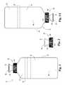
- FIG. 1is a front elevational view of an inverted squeeze foamer, in an upright orientation, according to a first embodiment.
- FIG. 1Ais a front elevational view of the FIG. 1 inverted squeeze foamer in its inverted, use orientation.
- FIG. 2is a front elevational view of a foamer, without the dip tube, in a closed condition, which comprises, as a subassembly, one part of the FIG. 1 inverted squeeze foamer.
- FIG. 3is a perspective view of the FIG. 2 foamer.
- FIG. 4is a top plan view of the FIG. 2 foamer.
- FIG. 5is a front elevational view, in full section, of the FIG. 2 foamer, with a portion of the dip tube added, as viewed along cutting plane 5 - 5 in FIG. 4 .
- FIG. 6is a front elevational view of the FIG. 2 foamer in an open condition.
- FIG. 7is a perspective view of the FIG. 6 foamer.
- FIG. 8is a front elevational view, in full section, of the FIG. 6 foamer, viewed in the same plane as FIG. 5 .
- FIG. 9is an enlarged, front elevational view, in full section, of the FIG. 5 structure.
- FIG. 10is a front elevational view of a top cap which comprises one component part of the FIG. 2 foamer.
- FIG. 11is a perspective view of the FIG. 10 top cap.
- FIG. 12is a top plan view of the FIG. 10 top cap.
- FIG. 13is a front elevational view, in full section, of the FIG. 10 top cap, as viewed along cutting plane 13 - 13 in FIG. 12 .
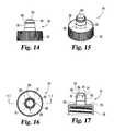
- FIG. 14is a front elevational view of a closure which comprises one component part of the FIG. 2 foamer.
- FIG. 15is a perspective view of the FIG. 14 closure.
- FIG. 16is a top plan view of the FIG. 14 closure.
- FIG. 17is a front elevational view, in full section, of the FIG. 14 closure, as viewed along cutting plane 17 - 17 in FIG. 16 .
- FIG. 18is a front elevational view of a housing which comprises one component part of the FIG. 2 foamer.
- FIG. 19is a perspective view of the FIG. 18 housing.
- FIG. 20is a top plan view of the FIG. 18 housing.
- FIG. 21is a front elevational view, in full section, of the FIG. 18 housing, as viewed along cutting plane 21 - 21 in FIG. 20 .
- FIG. 22is a side elevational view, in full section, of the FIG. 18 housing, as viewed along cutting plane 22 - 22 in FIG. 20 .
- FIG. 23is a front elevational view of a diaphragm which comprises one component part of the FIG. 2 foamer.
- FIG. 24is a perspective view of the FIG. 23 diaphragm.
- FIG. 25is a top plan view of the FIG. 23 diaphragm.
- FIG. 26is a front elevational view, in full section, of the FIG. 23 diaphragm, as viewed along cutting plane 26 - 26 in FIG. 25 .
- FIG. 27is a front elevational view of a mesh insert which comprises one component part of the FIG. 2 foamer.
- FIG. 28is a perspective view of the FIG. 27 mesh insert.
- FIG. 29is a top plan view of the FIG. 27 mesh insert.
- FIG. 30is a front elevational view, in full section, of the FIG. 27 mesh insert, as viewed along cutting plane 30 - 30 in FIG. 29 .
- FIG. 31is a front elevational view of a duckbill valve which comprises one component part of the FIG. 2 foamer.
- FIG. 32is a perspective view of the FIG. 31 duckbill valve.
- FIG. 33is a top plan view of the FIG. 31 duckbill valve.
- FIG. 34is a side elevational view, in full section, of the FIG. 31 duckbill valve, as viewed along cutting plane 34 - 34 in FIG. 33 .
- FIG. 35is a front elevational view, in full section, of the FIG. 31 duckbill valve, as viewed along cutting plane 35 - 35 in FIG. 33 .
- FIG. 36is a side elevational view of a duckbill holder which comprises one component part of the FIG. 2 foamer.
- FIG. 37is a perspective view of the FIG. 36 duckbill holder.
- FIG. 38is a top plan view of the FIG. 36 duckbill holder.
- FIG. 39is a front elevational view, in full section, of the FIG. 36 duckbill holder, as viewed along cutting plane 39 - 39 in FIG. 38 .
- FIG. 40is a side elevational view, in full section, of the FIG. 36 duckbill holder, as viewed along cutting plane 40 - 40 in FIG. 38 .
- FIG. 41is a perspective view of an alternate embodiment of a foamer which is suitable for use, as a subassembly, as one part of the FIG. 1 inverted squeeze foamer.
- FIG. 42is a top plan view of the FIG. 41 foamer.
- FIG. 43is a front elevational view, in full section, of the FIG. 41 foamer, as viewed along cutting plane 43 - 43 in FIG. 42 .
- FIG. 44is an angled side elevational view, in full section, of the FIG. 41 foamer, as viewed along cutting plane 44 - 44 in FIG. 42 .
- FIG. 45is a front elevational view, in full section, of the FIG. 41 foamer as assembled to the FIG. 1 container, with liquid product.
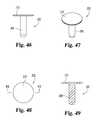
- FIG. 46is a front elevational view of a metering valve which comprises one component part of the FIG. 41 foamer.
- FIG. 47is a perspective view of the FIG. 46 metering valve.
- FIG. 48is a top plan view of the FIG. 46 metering valve.
- FIG. 49is a front elevational view, in full section, of the FIG. 46 metering valve, as viewed along cutting plane 49 - 49 in FIG. 48 .
- FIG. 50is a side elevational view of a metering valve holder which comprises one component part of the FIG. 41 foamer.
- FIG. 51is a perspective view of the FIG. 50 metering valve holder.
- FIG. 52is a top plan view of the FIG. 50 metering valve holder.
- FIG. 53is a side elevational view, in full section, of the FIG. 50 metering valve holder, as viewed along cutting plane 53 - 53 in FIG. 52 .
- FIG. 54is an angled side elevational view, in full section, of the FIG. 50 metering valve holder, as viewed along cutting plane 54 - 54 in FIG. 52 .
- FIG. 1there is illustrated an inverted squeeze foamer 20 which includes container 22 , a supply of liquid product 24 and foamer 26 .
- a completed squeeze foamer 20filled with product 24 , could be sold in that completed condition to a distributor, to a wholesaler or to a discount or retail outlet.
- the container 22 and foamer 26could be sold as a combination, without product, to a filler.
- FIG. 1shows the entire inverted squeeze foamer 20 including container 22 and liquid product 24 . However, the focus of this disclosure and of the exemplary embodiment is on the foamer 26 .
- the exemplary embodiment, as illustrated herein,is described as being an “inverted” squeeze foamer.
- its normal, not in use conditionis with the base of the container resting on a shelf, countertop or similar substantially horizontal surface.
- the top cap 28 which is adjacent the dispensing end 30has a substantially planar lower edge 32 .
- the inverted squeeze foamer 20can be set, when not in use, on edge 32 .
- This inverted, at rest conditionis illustrated in FIG. 1A .
- the dispensing end 30is thus oriented, in the FIG. 1 condition, as the highest or uppermost portion of the inverted squeeze foamer.
- the inverted squeeze foamerin this condition, has a longitudinal axis which is substantially vertical.
- invertedrefers to the fact that when the user desires to dispense a portion of the liquid product 24 , as foam or with a foam consistency, the inverted squeeze foamer is inverted such that the base of container 22 is above (i.e. higher) than dispensing end 30 .
- One reason for invertingis due to the manner and direction in which the foamed product is dispensed.
- the use of “inverted”is intended to also clarify and to differentiate this general style of dispenser from that category or style of dispenser which is typically referred to as “upright”.
- Foamer 26in addition to top cap 28 , includes closure 34 , housing 36 , diaphragm 38 , mesh insert 40 , annular gasket 42 , duckbill valve 44 , duckbill valve holder 46 and dip tube 48 .
- the dip tube 48can be considered a part of foamer 26 or can be considered a separate component part.
- One reason to perhaps consider the dip tube 48 as a separate component partis the ability and the option of exchanging dip tubes in order to change the size of the inside diameter as this would affect the volumertric flow rate of the air.
- the positional and assembly relationships of the component parts which comprise foamer 26are illustrated in FIGS. 2-5 and 9 .
- cap 28 , 34 , 36 , 38 , 40 , 42 , 44 , 46 and 48are assembled together without using any adhesives, bonding agents, threaded fasteners or the use of ultrasonic welding.
- An axial, sliding relationship between cap 28 and closure 34defines, in part, dispensing end 30 .
- Mesh insert 40is received in part by housing 36 and in part by closure 34 . Portions of housing 36 are received by closure 34 .
- Closure 34is constructed and arranged to assemble to the neck of the container 22 .
- the duckbill valve 44assembles into duckbill valve holder 46 and this combination is received by housing 36 .
- the duckbill valve holder 46includes a dip tube sleeve 50 which receives the dip tube 48 with an interference fit.
- the diaphragm 38is positioned above the duckbill holder 46 and includes an upper annular wall which received a lower annular wall of the housing 36 .
- the gasket 42is positioned so as to help seal the threaded assembly closure 34 with the neck of the container. Gasket 42 is preferably a square cut annular gasket, but alternatively could be an O-ring.
- FIGS. 2-5show the foamer 26 in a closed, at rest condition, not yet inverted.
- FIGS. 6-8show the foamer 26 in an open, at rest condition, ready for foam dispensing out of dispensing end 30 , once the foamer is inverted.
- the inverted squeeze foamer 20should be inverted, see FIGS. 1A and 9 , so that liquid product flows through duckbill valve 44 and so that the free end of the dip tube 48 is in communication with the air 52 (air pocket) in container 22 which is above the level of liquid product 24 in the inverted orientation of FIG. 1A .
- each component part 28 , 34 , 36 , 38 , 40 , 42 and 48is generally symmetrical about a diametrical cutting plane.
- the manual squeezing of the container 22 so as to draw generally opposing portions of the pliable sidewall 54 closer togethercauses an increase in the internal pressure.
- This increase in the internal pressurecreates an air flow via dip tube 48 and creates a flow of the liquid product 24 downwardly through the duckbill valve 44 .
- the volume of the containeris reduced and the internal forces which are generated cause the trapped air to try and find an exit path of least resistance.
- This internal pressurealso causes the liquid product to try and find an exit path of least resistance.
- FIG. 9an enlarged view of foamer 26 is illustrated. In use this orientation would be inverted. Only a portion of the dip tube 48 is shown in order to focus on the details of the other component parts.
- the specific flow path for the air, when inverted,is in and down through dip tube 48 .
- the specific flow path for liquid product 24when inverted, is into the upper end of the duckbill valve 44 .
- the internal pressurecreates a sufficient liquid flow force to open the valve and thereby allow the air and liquid product to mix before that mixture is pushed through mesh insert 40 .
- the closure 34includes a lower, generally cylindrical skirt 58 which is internally threaded for threaded connection to the threaded neck 60 of container 22 .
- the exemplary embodimentshows internal threads on the skirt 58 and there are cooperating external threads on the neck 60 .
- this form of threaded engagementcould be reversed.
- the foamer 26 and container 22could be securely assembled together, into a leak-free combination, by means of a snap-fit combination or an interference fit. Techniques such as the use of ultrasonic welding or the use of adhesives are not suitable since as a practical matter they can only be employed after the container is filled with liquid product.
- Cap 28as a separate component part, is illustrated in FIGS. 10-13 .
- Cap 28includes an annular, flared outer wall 62 and an inner, annular wall 64 which defines annular opening 66 .
- Wall 62curves inwardly, in a “downward” direction to free end 68 which defines the generally annular interior 70 .
- the use of directional references, such as “downwardly”, in the description of the component partis based on the FIG. 1 orientation (at rest) of inverted squeeze foamer 20 .
- Inwardly directed rib 72is an abutment stop for the relative movement between cap 28 and closure 34 .
- Closure 34includes a radially outwardly-extending rib 74 which slides against the interior annular surface 76 of cap 28 .
- Annular lip 78abuts against ledge 80 when cap 28 and closure 34 are “closed”. This abutment between lip 78 and ledge 80 closes off any foam flow openings or separation, effectively sealing closed the foamer 26 .
- Closure 34as separate component part, is illustrated in FIGS. 14-17 .
- Closure 34includes, in addition to those structural portions already described, a threaded body including skirt 58 , an annular stem 85 and an annular upper shelf 86 positioned between stem 85 and skirt 58 which defines an equally-spaced pattern of four (4) air openings 88 which supply make-up air into the container 22 .
- the valving structure of diaphragm 38helps to control when and how make-up air is drawn into container 22 after a portion of liquid product 24 is dispensed with a foam consistency.
- internal pressure due to squeezing of the pliable container sidewall 54causes an inner edge portion of the diaphragm 38 to push open for delivering air in order to mix with the liquid product.
- the containertries to return to its original shape. This in turn creates a suction force and an outer edge portion or portions of the diaphragm 38 pull away from its valve seat (part of housing 36 ) and air is sucked into the container via openings 88 . Additional details of this described air flow are provided later in conjunction with a description of other component parts.
- Housing 36as a separate component part, is illustrated in FIGS. 18-22 .
- Housing 36includes an internally-stepped or offset outer wall 90 extending integrally into upper radial flange 92 .
- the outer surface 94 of outer wall 90is generally cylindrical.
- the radial flange 92is generally cylindrical and generally concentric with outer wall 90 .
- Inwardly offset portion 96is generally cylindrical and integrally extends into intermediate annular shelf 98 . Shelf 98 defines an equally-spaced pattern of eight (8) make-up air openings 100 .
- the flow of make-up air which enters via openings 88continues through openings 100 and past diaphragm 38 in order to flow into container 22 (see FIG. 9 ). This incoming flow of make-up air must enter the container via dip tube 48 .
- Lower wall portion 102is generally cylindrical and defines two (2) annular recessed grooves 104 a and 104 b which function as snap-fit detents in cooperation with raised annular ribs 106 a and 106 b (annular bumps) on the outer surface of outer wall 108 of duckbill holder 46 for a snap-fit assembly between these two (2) component parts (see FIG. 9 ).
- the annular ledge 110which corresponds to the radial offset between portion 96 and wall 102 provides the valve seat 110 for the outer edge portion 112 of the diaphragm 38 .
- Interior sleeve 114which is integral with shelf 98 is generally cylindrical and generally concentric with outer wall 90 .
- Sleeve 114includes an upper portion 116 axially above shelf 98 and a lower portion 118 axially below shelf 98 .
- Upper portion 116includes three (3) small raised (radially inwardly) annular ribs 120 a , 120 b and 120 c for an interference fit with the outer cylindrical wall 121 of mesh insert 40 .
- the lower surface or edge 122 of mesh insert 40abuts up against upper surface 124 of mix portion 126 .
- the interior space or volume defined by mix portion 126allows initial mixing of the air flow and the portion of liquid product 24 being withdrawn from container 22 .
- Lower portion 118receives the upper (tapered) tip 128 of duckbill valve 44 (see FIG. 9 ). Clearance is provided between lower portion 118 and duckbill valve 44 for the flow of air from within the container 22 for mixing with the flow of liquid product which flows through duckbill valve 44 .
- the interior shapes, openings, clearances, etc. of mix portion 126 and of lower portion 118are each constructed and arranged in order to facilitate the desired and intended flows of air and of liquid product and the desired and intended mixing of those two (2) flows before being pushed through the mesh insert 40 for foam aeration and for creating a desired foam consistency for the liquid product for dispensing.
- the raised annular ribs 130 a and 130 b on the outer surface of upper portion 116are used to facilitate and secure the interference fit of the axially upper end of portion 116 into stem 85 of closure 34 .
- the raised annular ribs 132 a and 132 b on the outer surface of lower portion 118are used to facilitate and secure the snap-fit assembly of lower portion 118 into the upper end 134 of the generally cylindrical body 136 of diaphragm 38 .
- the inner surface 138defines a pair of raised annular ribs 140 a and 140 b which are constructed and arranged to cooperate with ribs 132 a and 132 b for the snap-fit (snap-over) assembly.
- these component part portionsare generally cylindrical and include or define some type of assembly structure. Described thus far are raised annular ribs, usually a plurality, and recessed annular grooves or what would be described as detents in a more functional sense.
- any assembly technique or combinationmay be used for virtually any portion of the exemplary embodiments. These options include the following.
- One optionis to provide one (1) or more raised annular ribs on one (1) part and one (1) or more recessed annular grooves on the other part.
- the snap-fit of the ribs into the grooveshelps to secure the assembly of these two (2) component parts.
- This assembly techniquemay be used with closely sized parts which may also provide a sliding fit or even an interference fit in addition to the rib-groove interfit.
- Another optionis to provide only the one (1) or more raised annular ribs on one of the parts.
- the mating partsimply provides a closely sized and similarly shaped surface which creates an interference fit or perhaps a close sliding fit relative to the raised annular ribs. When an interference fit exists, this interference fit actually anchors the two (2) parts together. With plastic parts, and depending on the degree of interference, the ribs may actually “indent” into the other part thereby adding a type of interlock to the assembly.
- a still further optionis to provide one (1) or more raised annular ribs on each part.
- This arrangementhas the rib or ribs on one part snapping over one or more of the ribs on the other part.
- Diaphragm 38as a separate component part, is illustrated in FIGS. 23-26 .
- Diaphragm 38includes, in addition to those portions already described, an annular sealing flange 142 with a flexible annular inner lip 144 and a lower, generally cylindrical edge 145 defining four (4), spaced-apart air flow notches 146 . Air flowing from the container via dip tube 48 flows through the notches 146 and pushes open (i.e. lifts) inner lip 144 for the air flow to reach mix portion 126 .
- edge portion 112functions as a valve seal and ledge 110 functions as the cooperating valve seat for the flow of make-up air.
- inner lip 144functions as a valve seal and the upper annular edge 148 of holder 46 functions as the cooperating valve seat for the flow of air from container 22 for foam aeration.
- Lip 144is shaped with a slight incline and edge 148 has a similar slight incline.
- Edge portion 112is also shaped with a slight incline. In the “at rest” condition with the container placed on a support surface, these slight inclines are in an axially upward direction. In the inverted condition of the squeeze foamer 20 , when it is intended to dispense foam, these slight inclines are in an axially downward direction.
- mesh insert 40as a separate component part, is illustrated in FIGS. 27-30 .
- mesh insert 40includes an enlarged portion 150 which is generally cylindrical and generally concentric with wall 121 .
- Edge 122defines an opening which receives a coarse mesh screen 152 .
- Portion 150defines an opening which receives a fine mesh screen 154 .
- two (2) mesh screensare provided and these two (2) mesh screens 152 and 154 are incorporated into mesh insert 40 .
- additional mesh screenscan be used or the foamer could include a single mesh screen.
- the mesh screenscan be integrated into other component parts of the foamer, such as into closure 34 and/or housing 36 . This integration may be an integrally molded combination or a snap-in assembly of the mesh screen into the other part or a press-in or interference fit assembly.
- mesh screens 152 and 154are installed into the hollow interior of the mesh insert body. Alternatively, each mesh screen 152 and 154 may be bonded to their corresponding end faces of the mesh insert body.
- Duckbill valve 40as a separate component part, is illustrated in FIGS. 31-35 .
- Duckbill valve 44includes in addition to tip 128 , a base 156 which includes an annular enlarged portion 158 for a snap-fit assembly into holder 46 .
- the tip 128 and base 156cooperatively define a hollow interior 160 .
- Tip 128includes flat tapered sides 162 and 164 which converge toward upper edge 166 .
- Edge 166defines a slit 168 whose sides or edges separate to enlarge the opening in response to a flow of liquid product through interior 160 . In a reverse direction, slit 168 is essentially closed to any type of reverse flow of liquid product or foam.
- Duckbill valve holder 46as a separate component part, is illustrated in FIGS. 36-40 .
- holder 46includes an outer annular wall 170 , an inner annular wall 172 and an annular connecting portion 174 .
- Wall 170integrally extends into annular flange 176 which extends radially outwardly of wall 170 and thereby defines an abutment surface 178 which cooperates with the lower edge 180 of lower wall portion 102 of housing 36 .
- the dispensing of the liquid product 24 with a foam consistencybegins in the inverted orientation with cap 28 moved to an “open” condition relative to closure 34 .
- the next step or eventis the manual squeezing of the pliable sidewall 54 of container 22 .
- the liquid productis in direct contact with foamer 26 and the open, free end of the dip tube 48 is positioned in the air 52 pocket or air volume which is above the volume of liquid product 24 .
- This manual squeezing forcecreates an internal pressure within container 22 and this pressure causes two (2) flows.
- One (1) flowis of the liquid product 24 into duckbill valve 44 and the other flow is of air through dip tube 48 .
- These two (2) flowsmix in the vicinity of mix portion 126 and this mixture is then forced or pushed through the mesh insert 40 .
- the air-liquid product mixtureundergoes a first foam aeration step as it is pushed through coarse mesh screen 152 and then undergoes a second foam aeration step as the coarse foam is pushed through the fine mesh screen 154 .
- the foam exiting from the mesh insert 40is then dispensed.
- the pliable nature of the container sidewallcauses that sidewall to try and return to its original state or prior status.
- a suction forceis created internally as well as through dip tube 48 which thereby opens the air valve which is provided by the combination of edge portion 112 and ledge 110 .
- Thisallows a flow of make-up air to enter the container and this flow of make-up air continues until the internal pressure within container 22 is restored or returned to substantially atmospheric pressure.
- the diaphragmseals closed back to its starting or at rest condition.
- the vent flow rateis between approximately 0.01 liters per minute and 0.10 liters per minute at a differential pressure of 40 mbar (0.58 psi).
- One feature of the present disclosure and of the illustrated exemplary embodimentsis the ability to easily assemble the component parts into the final foamer 26 construction.
- the sameis true for the second embodiment of foamer 200 which is described herein.
- This ease of assembly featurebegins with the snap-fit or interference fit (these variations and their interchangeable aspects have been explained) assembly of four (4) component parts into a first subassembly.
- This first subassemblyprovides the assembly of the housing 36 , the mesh insert 40 , the diaphragm 38 and gasket 42 .
- the second subassemblyprovides the assembly of the duckbill valve 44 and holder 46 .
- the third subassemblyputs the first two (2) subassemblies together in combination with the top cap 28 .
- the final assembly stepis to insert the dip tube 48 into sleeve 50 thereby converting the third subassembly into the final foamer construction.
- foamer 200represents the second embodiment and the only relevant or applicable difference between foamer 26 and foamer 200 is the elimination of duckbill valve 44 and holder 46 from foamer 26 and replacement with a metering valve 202 and a different style of holder 204 as part of foamer 200 . Except for these differences, the two (2) foamers 26 and 200 are essentially the same in all other important aspects.
- Foamer 200includes cap 28 , closure 34 , housing 36 , diaphragm 38 , mesh insert 40 , gasket 42 , metering valve 202 , metering valve holder 204 and dip tube 48 .
- the duckbill valve 44 and holder 46have been exchanged for valve 202 and holder 204 .
- All other aspects of foamer 26are essentially found in foamer 200 .
- Foamer 200is also fully compatible with container 22 as the closure 34 and dip tube 48 are the same as found in inverted squeeze foamer 20 .
- FIG. 45illustrates the inverted orientation of inverted squeeze foamer 206 which includes foamer 200 , container 22 and liquid product 24 .
- Metering valve 202is illustrated in FIGS. 46-49 .
- Metering valve 202includes a generally cylindrical post 208 and a generally cylindrical flange 210 .
- the post 208 and flange 210are generally concentric and are of a molded plastic construction as a single-piece component.
- FIGS. 50-54Metering valve holder 204 , as a separate component part, is illustrated in FIGS. 50-54 .
- Holder 204includes a dip tube sleeve 50 which is essentially the same in form, fit and function as the sleeve which is part of holder 46 . Otherwise, holders 46 and 204 are of different constructions, representative of their relationship to and cooperation with valves of different construction, specifically valves 44 and 202 .
- holder 204further includes outer annular wall 212 , inner annular post 214 , base 216 and annular stepped transitional portion 218 .
- Post 214is constructed and arranged with a center stem 220 which is connected to post 214 by means of four (4) integral spokes 222 .
- the openings 224 between adjacent spokes 222define flow passages for liquid product.
- Raised annular ribs 226 a and 226 bprovide the means for a snap-fit, interference fit or snap-over fit with housing 36 .
- the base 216defines annular inlet 227 .
- Stem 220defines a generally cylindrical bore 228 which is constructed and arranged to receive post 208 with a closely sized interference fit.
- flange 210With post 208 fully inserted into bore 228 , flange 210 becomes preloaded into a curved form resting on the upper inside edge 230 of post 214 .
- some portion or portions of the outer edge of flange 210are forced off of or out of contact with edge 230 . In turn, this creates a flow opening (or openings) for the liquid product which is forced into inlet 227 to pass into the vicinity of mix portion 126 of housing 36 .
- the control and management of the volumetric flows, flow rates, ratios and proportionsdetermine some of the characteristics of the foam which is dispensed.
- the mesh insertalso plays a part, but the liquid-air mix ratio is critical and is independent of the number and style of mesh screens.
- Another relevant factoris the valve-opening pressure level for the duckbill valve 44 and for the metering valve 202 .
- the duckbill valve 44opens in response to a lower liquid flow force or pressure than that required to deflect the edges of the metering valve 202 .
- the foam dispensed from squeeze foamer 20will have a higher moisture content than the foam dispensed from squeeze foamer 206 .
- the foam from the squeeze foamer 206will be less dense.
- foamer 26 with the duckbill valve 44has produced a foam which has a density of 0.078 grams per cubic centimeter.
- the foam density or “consistency”will be understood from this representative number which also relates to a liquid percentage and relates to the mix ratio which can be calculated on a volumetric basis.
- This representative foam densitywill also be understood in relative terms noting that the density of water is approximately 1.0 grams per cubic centimeter.
- foamer 200 with the metering valve 202is constructed and arranged to dispense a “lighter” foam, due to more air and less liquid.
- the designed density of the foam being dispensedranges from approximately 0.012 grams per cubic centimeter to approximately 0.05 grams per cubic centimeter.
- all of the component parts of foamers 26 and 200 with the exception of the dip tubeare unitary, single-piece molded component parts which are fabricated out of a suitable thermoforming or thermosetting plastic.
- the preferred material for the mesh insertis nylon and the preferred material for the dip tube is polyethylene.
Landscapes
- Health & Medical Sciences (AREA)
- Public Health (AREA)
- Closures For Containers (AREA)
- Containers And Packaging Bodies Having A Special Means To Remove Contents (AREA)
- Nozzles (AREA)
Abstract
Description
Claims (23)
Priority Applications (1)
| Application Number | Priority Date | Filing Date | Title |
|---|---|---|---|
| US14/036,403US9718070B2 (en) | 2012-08-31 | 2013-09-25 | Inverted squeeze foamer |
Applications Claiming Priority (3)
| Application Number | Priority Date | Filing Date | Title |
|---|---|---|---|
| US201261695525P | 2012-08-31 | 2012-08-31 | |
| PCT/US2013/054889WO2014035669A1 (en) | 2012-08-31 | 2013-08-14 | Inverted squeeze foamer |
| US14/036,403US9718070B2 (en) | 2012-08-31 | 2013-09-25 | Inverted squeeze foamer |
Related Parent Applications (1)
| Application Number | Title | Priority Date | Filing Date |
|---|---|---|---|
| PCT/US2013/054889ContinuationWO2014035669A1 (en) | 2012-08-31 | 2013-08-14 | Inverted squeeze foamer |
Publications (2)
| Publication Number | Publication Date |
|---|---|
| US20140061247A1 US20140061247A1 (en) | 2014-03-06 |
| US9718070B2true US9718070B2 (en) | 2017-08-01 |
Family
ID=50184144
Family Applications (1)
| Application Number | Title | Priority Date | Filing Date |
|---|---|---|---|
| US14/036,403Active2033-08-19US9718070B2 (en) | 2012-08-31 | 2013-09-25 | Inverted squeeze foamer |
Country Status (8)
| Country | Link |
|---|---|
| US (1) | US9718070B2 (en) |
| EP (1) | EP2890502B1 (en) |
| JP (1) | JP2015531726A (en) |
| KR (1) | KR20150046296A (en) |
| CN (1) | CN104736254B (en) |
| CA (1) | CA2883370A1 (en) |
| MX (1) | MX358783B (en) |
| WO (1) | WO2014035669A1 (en) |
Cited By (12)
| Publication number | Priority date | Publication date | Assignee | Title |
|---|---|---|---|---|
| WO2019139890A1 (en)* | 2018-01-09 | 2019-07-18 | Rieke Corporation | Reduced force, sealing vent for squeeze foamer |
| US10766672B2 (en) | 2018-12-12 | 2020-09-08 | Yeti Coolers, Llc | Insulating container |
| US10898911B2 (en)* | 2015-12-15 | 2021-01-26 | Taplast S.R.L. | Device for dispensing a mixture, preferably a foam, and system using said device |
| US11253879B2 (en) | 2017-11-10 | 2022-02-22 | Taplast S.R.L. | Device for dispensing a mixture, preferably a foam, and system using said device |
| USD951403S1 (en) | 2019-12-04 | 2022-05-10 | Sloan Valve Company | Valve |
| WO2022109236A1 (en) | 2020-11-19 | 2022-05-27 | Rieke Llc | Squeeze foamer with low profile closure and drip resistant vent |
| USD965409S1 (en) | 2018-12-12 | 2022-10-04 | Yeti Coolers, Llc | Latch portion |
| US20230256691A1 (en)* | 2020-07-09 | 2023-08-17 | Active Tools International (Hk) Ltd. | Sealant Bottle |
| US11958066B2 (en) | 2020-06-02 | 2024-04-16 | RLM Group Ltd. | Sustainable packaging assemblies |
| US11970313B2 (en) | 2018-12-12 | 2024-04-30 | Yeti Coolers, Llc | Insulating container |
| IT202300006747A1 (en) | 2023-04-06 | 2024-10-06 | Rieke Packaging Systems Ltd | MODULAR NETWORK COMPONENT FOR FOAM DISPENSERS AND TOOLS AND METHODS FOR MANUFACTURING THE SAME |
| US12139307B2 (en) | 2020-03-12 | 2024-11-12 | RLM Group Ltd. | Container comprising a duckbill valve and a leak-resistant closure mechanism |
Families Citing this family (10)
| Publication number | Priority date | Publication date | Assignee | Title |
|---|---|---|---|---|
| EP2890502B1 (en)* | 2012-08-31 | 2018-11-28 | Arminak & Associates, LLC | Inverted squeeze foamer |
| US9586217B2 (en)* | 2012-10-04 | 2017-03-07 | Arminak & Associates, Llc | Mixing chamber for two fluid constituents |
| CN104443722B (en)* | 2014-10-24 | 2016-08-17 | 梅元红 | A kind of method that squash type foam pump and foam pump produce foam |
| JP2016161601A (en)* | 2015-02-26 | 2016-09-05 | リコーイメージング株式会社 | Drip-proof connection mechanism and electronic apparatus |
| KR101701773B1 (en)* | 2015-10-13 | 2017-02-13 | 주식회사 아폴로산업 | Foaming generater for squeeze bottle |
| WO2018064118A1 (en)* | 2016-09-27 | 2018-04-05 | Rieke Packaging Systems Limited | Squeeze sprayer for fluid products |
| CN108163354B (en)* | 2018-01-03 | 2023-10-10 | 中山市联昌喷雾泵有限公司 | Inverted extrusion foam pump |
| CN109229842A (en)* | 2018-09-05 | 2019-01-18 | 中山市华宝勒生活用品实业有限公司 | A kind of dosing container squeezing out liquid |
| EP3906119B1 (en)* | 2019-01-03 | 2025-10-15 | Aptar Radolfzell GmbH | Nozzle unit, liquid dispenser comprising such a nozzle unit, and method for producing such nozzle units |
| KR102444118B1 (en)* | 2022-01-05 | 2022-09-19 | (주)나산기업 | A foam discharge apparatus |
Citations (63)
| Publication number | Priority date | Publication date | Assignee | Title |
|---|---|---|---|---|
| US3176883A (en)* | 1963-04-15 | 1965-04-06 | Jr George B Davis | Fluid dispenser |
| US3622049A (en) | 1969-05-05 | 1971-11-23 | Schering Corp | Dispensing system |
| US3709437A (en) | 1968-09-23 | 1973-01-09 | Hershel Earl Wright | Method and device for producing foam |
| US3937364A (en) | 1975-04-03 | 1976-02-10 | Hershel Earl Wright | Foam dispensing device |
| US3985271A (en) | 1975-06-06 | 1976-10-12 | Glasrock Products, Inc. | Foam generating and dispensing device |
| US4118152A (en) | 1976-06-02 | 1978-10-03 | Dan Bron | Pump for variable dosing |
| US4147306A (en)* | 1977-09-28 | 1979-04-03 | Bennett Robert S | Foam producing apparatus |
| US4184615A (en) | 1975-04-03 | 1980-01-22 | Wright Hershel E | Foam dispensing device |
| US4274594A (en) | 1977-12-06 | 1981-06-23 | Toyo Seikan Kaisha Ltd. | Foam generating and dispensing device |
| US4360130A (en) | 1979-10-16 | 1982-11-23 | Duskin Franchise Kabushiki Kaisha | Dispenser, particularly for liquid soap |
| US4364718A (en) | 1981-02-24 | 1982-12-21 | Internationale Octrooi Maatschappij "Octropa" Bv | Disposable pump for dispensing small metered amounts of liquid from a container and a control unit for operating said pump |
| US4396152A (en) | 1977-03-02 | 1983-08-02 | Abplanalp Robert H | Aerosol dispenser system |
| US4589573A (en) | 1982-06-29 | 1986-05-20 | Canyon Corporation | Head depression type dispenser |
| US4673109A (en) | 1985-10-18 | 1987-06-16 | Steiner Company, Inc. | Liquid soap dispensing system |
| US4730751A (en) | 1986-05-16 | 1988-03-15 | Leonard Mackles | Squeeze bottle powder dispenser |
| US4880161A (en) | 1985-01-28 | 1989-11-14 | Earl Wright Company | Foam dispensing device |
| US5037006A (en) | 1990-03-27 | 1991-08-06 | The Procter & Gamble Company | Squeeze bottle foam dispenser with threshold pressure valve |
| US5165577A (en) | 1991-05-20 | 1992-11-24 | Heiner Ophardt | Disposable plastic liquid pump |
| US5186364A (en) | 1990-11-20 | 1993-02-16 | Telekesi Laszlo | Dispensing head for applying foamy product on a skin surface |
| US5219102A (en) | 1990-04-05 | 1993-06-15 | Earl Wright Company | Foaming device |
| US5271530A (en) | 1990-11-07 | 1993-12-21 | Daiwa Can Company | Foam dispensing pump container |
| US5282552A (en) | 1991-05-20 | 1994-02-01 | Hygiene-Technik Inc. | Disposable plastic liquid pump |
| US5337929A (en) | 1989-07-20 | 1994-08-16 | Airspray International B.V. | Mixing chamber for mixing a gaseous and a liquid component |
| US5373970A (en) | 1993-10-29 | 1994-12-20 | Hygiene-Technik Inc. | Liquid soap dispenser for simplified replacement of soap reservoir |
| US5443569A (en) | 1993-03-05 | 1995-08-22 | Daiwa Can Company | Foam dispensing pump container |
| US5445288A (en) | 1994-04-05 | 1995-08-29 | Sprintvest Corporation Nv | Liquid dispenser for dispensing foam |
| US5467898A (en) | 1993-05-05 | 1995-11-21 | Toyo Seikan Kaisha, Ltd. | Liquid foam-discharging, squeezable vessel |
| US5489044A (en) | 1991-05-20 | 1996-02-06 | Hygiene-Technik Inc. | Method of preparing replaceable liquid soap reservoir |
| US5518147A (en)* | 1994-03-01 | 1996-05-21 | The Procter & Gamble Company | Collapsible pump chamber having predetermined collapsing pattern |
| US5570819A (en) | 1992-07-07 | 1996-11-05 | Daiwa Can Company | Foam dispensing pump container |
| US5664703A (en)* | 1994-02-28 | 1997-09-09 | The Procter & Gamble Company | Pump device with collapsible pump chamber having supply container venting system and integral shipping seal |
| US5676277A (en) | 1991-05-20 | 1997-10-14 | Ophardt; Heiner | Disposable plastic liquid pump |
| KR0163093B1 (en) | 1994-12-19 | 1998-11-16 | 악퀴스 제이. 베리악 | Bubbler Assembly for Fluid Dispenser |
| EP0950434A1 (en) | 1998-03-20 | 1999-10-20 | Sofiplast, S.A. | Dispensing container provided with foaming device |
| US5975360A (en) | 1991-05-20 | 1999-11-02 | Ophardt; Heiner | Capped piston pump |
| US6082586A (en) | 1998-03-30 | 2000-07-04 | Deb Ip Limited | Liquid dispenser for dispensing foam |
| US6343724B1 (en) | 2000-07-10 | 2002-02-05 | Hygiene Technik Inc. | Unitary one-way valve for fluid dispenser |
| US6394315B1 (en) | 2000-05-08 | 2002-05-28 | Deb Ip Limited | Squeeze operated foam dispenser |
| US6398133B1 (en) | 1999-12-22 | 2002-06-04 | Emsar, Inc. | Dispensing head for a squeeze dispenser |
| US6402054B1 (en) | 2001-02-09 | 2002-06-11 | Saint-Gobain Calmar Inc. | Airless squeeze bottle aspirator |
| US6409050B1 (en) | 2001-03-20 | 2002-06-25 | Hygiene-Technik Inc. | Liquid dispenser for dispensing foam |
| US20020153389A1 (en) | 2000-05-08 | 2002-10-24 | Creaghan David Michael Ross | Squeeze operated foam dispenser |
| US6516976B2 (en) | 2000-12-19 | 2003-02-11 | Kimberly-Clark Worldwide, Inc. | Dosing pump for liquid dispensers |
| US6533145B2 (en) | 2000-12-19 | 2003-03-18 | Kimberly-Clark Worldwide, Inc. | Self-contained viscous liquid dispenser |
| US6536685B2 (en) | 2001-03-16 | 2003-03-25 | Unilever Home And Personal Care Usa, Division Of Conopco, Inc. | Foamer |
| US6540157B2 (en) | 2001-04-12 | 2003-04-01 | Heiner Ophardt | Nozzle for fluid dispenser |
| US6540117B2 (en) | 2001-03-30 | 2003-04-01 | Kimberly-Clark Worldwide, Inc. | Dosing pump for liquid dispensers |
| CN1407916A (en) | 1999-12-02 | 2003-04-02 | 塔普拉斯特有限公司 | Method of spraying liquids under form of foam by means of deformable containers and device using this method |
| US6868990B2 (en) | 2002-09-26 | 2005-03-22 | Emsar, Inc. | Fluid dispenser with shuttling mixing chamber |
| US6951295B1 (en) | 2005-01-18 | 2005-10-04 | Seaquist Closures Foreign, Inc. | Flow control element and dispensing structure incorporating same |
| US7464839B2 (en) | 2002-06-20 | 2008-12-16 | Rpc Wiko Gmbh | Dispenser head with a check valve |
| US20080314931A1 (en) | 2006-01-24 | 2008-12-25 | Rexam Airspray N.V. | Squeeze Foamer |
| CN101596509A (en) | 2008-05-28 | 2009-12-09 | 高爽工业公司 | Air Piston and Vault Foam Pump |
| US20100126523A1 (en)* | 2007-04-27 | 2010-05-27 | Kao Corporation | Two-part hair dye or bleach composition |
| US20100193547A1 (en)* | 2007-08-02 | 2010-08-05 | Leafgreen Limited | Manual pump type fluid dispenser and a method of manufacturing such a dispenser |
| US8042710B2 (en) | 2006-01-24 | 2011-10-25 | Rexam Airspray N.V. | Squeeze foamer |
| US8056769B2 (en) | 2006-01-24 | 2011-11-15 | Rexam Airspray N.V. | Squeeze foamer |
| US20120074171A1 (en) | 2008-02-08 | 2012-03-29 | Gojo Industries, Inc. | Bifurcated stem foam pump |
| US8187339B2 (en) | 2009-12-18 | 2012-05-29 | The Procter & Gamble Company | Foam hair colorant composition |
| US8430107B2 (en)* | 2011-03-11 | 2013-04-30 | Yu Chang Esthetics Consultant Co., Ltd. | Foam output device easy to produce foam |
| US20140008394A1 (en)* | 2012-07-03 | 2014-01-09 | Paulus Antonius Augustinus Höfte | Foam Generating Dispenser |
| US20140061247A1 (en)* | 2012-08-31 | 2014-03-06 | Arminak & Associates, Llc | Inverted squeeze foamer |
| US9220377B2 (en)* | 2012-08-02 | 2015-12-29 | Rubbermaid Commercial Products, Llc | Foam dispensing pump with decompression feature |
- 2013
- 2013-08-14EPEP13833626.8Apatent/EP2890502B1/ennot_activeNot-in-force
- 2013-08-14WOPCT/US2013/054889patent/WO2014035669A1/enactiveApplication Filing
- 2013-08-14KRKR1020157007701Apatent/KR20150046296A/ennot_activeWithdrawn
- 2013-08-14CNCN201380056397.XApatent/CN104736254B/ennot_activeExpired - Fee Related
- 2013-08-14MXMX2015002698Apatent/MX358783B/enactiveIP Right Grant
- 2013-08-14JPJP2015529842Apatent/JP2015531726A/enactivePending
- 2013-08-14CACA2883370Apatent/CA2883370A1/ennot_activeAbandoned
- 2013-09-25USUS14/036,403patent/US9718070B2/enactiveActive
Patent Citations (70)
| Publication number | Priority date | Publication date | Assignee | Title |
|---|---|---|---|---|
| US3176883A (en)* | 1963-04-15 | 1965-04-06 | Jr George B Davis | Fluid dispenser |
| US3709437A (en) | 1968-09-23 | 1973-01-09 | Hershel Earl Wright | Method and device for producing foam |
| US3622049A (en) | 1969-05-05 | 1971-11-23 | Schering Corp | Dispensing system |
| US3937364A (en) | 1975-04-03 | 1976-02-10 | Hershel Earl Wright | Foam dispensing device |
| US4184615A (en) | 1975-04-03 | 1980-01-22 | Wright Hershel E | Foam dispensing device |
| US3985271A (en) | 1975-06-06 | 1976-10-12 | Glasrock Products, Inc. | Foam generating and dispensing device |
| US4118152A (en) | 1976-06-02 | 1978-10-03 | Dan Bron | Pump for variable dosing |
| US4396152A (en) | 1977-03-02 | 1983-08-02 | Abplanalp Robert H | Aerosol dispenser system |
| US4147306A (en)* | 1977-09-28 | 1979-04-03 | Bennett Robert S | Foam producing apparatus |
| US4274594A (en) | 1977-12-06 | 1981-06-23 | Toyo Seikan Kaisha Ltd. | Foam generating and dispensing device |
| US4360130A (en) | 1979-10-16 | 1982-11-23 | Duskin Franchise Kabushiki Kaisha | Dispenser, particularly for liquid soap |
| US4364718A (en) | 1981-02-24 | 1982-12-21 | Internationale Octrooi Maatschappij "Octropa" Bv | Disposable pump for dispensing small metered amounts of liquid from a container and a control unit for operating said pump |
| US4589573A (en) | 1982-06-29 | 1986-05-20 | Canyon Corporation | Head depression type dispenser |
| US4880161A (en) | 1985-01-28 | 1989-11-14 | Earl Wright Company | Foam dispensing device |
| US4673109A (en) | 1985-10-18 | 1987-06-16 | Steiner Company, Inc. | Liquid soap dispensing system |
| US4730751A (en) | 1986-05-16 | 1988-03-15 | Leonard Mackles | Squeeze bottle powder dispenser |
| US5337929A (en) | 1989-07-20 | 1994-08-16 | Airspray International B.V. | Mixing chamber for mixing a gaseous and a liquid component |
| US5037006A (en) | 1990-03-27 | 1991-08-06 | The Procter & Gamble Company | Squeeze bottle foam dispenser with threshold pressure valve |
| US5219102A (en) | 1990-04-05 | 1993-06-15 | Earl Wright Company | Foaming device |
| US5271530A (en) | 1990-11-07 | 1993-12-21 | Daiwa Can Company | Foam dispensing pump container |
| US5186364A (en) | 1990-11-20 | 1993-02-16 | Telekesi Laszlo | Dispensing head for applying foamy product on a skin surface |
| US5489044A (en) | 1991-05-20 | 1996-02-06 | Hygiene-Technik Inc. | Method of preparing replaceable liquid soap reservoir |
| US5282552A (en) | 1991-05-20 | 1994-02-01 | Hygiene-Technik Inc. | Disposable plastic liquid pump |
| US5165577A (en) | 1991-05-20 | 1992-11-24 | Heiner Ophardt | Disposable plastic liquid pump |
| US5975360A (en) | 1991-05-20 | 1999-11-02 | Ophardt; Heiner | Capped piston pump |
| US5676277A (en) | 1991-05-20 | 1997-10-14 | Ophardt; Heiner | Disposable plastic liquid pump |
| US5570819A (en) | 1992-07-07 | 1996-11-05 | Daiwa Can Company | Foam dispensing pump container |
| US5443569A (en) | 1993-03-05 | 1995-08-22 | Daiwa Can Company | Foam dispensing pump container |
| US5467898A (en) | 1993-05-05 | 1995-11-21 | Toyo Seikan Kaisha, Ltd. | Liquid foam-discharging, squeezable vessel |
| US5431309A (en) | 1993-10-29 | 1995-07-11 | Hygiene-Technik Inc. | Liquid soap dispenser for simplified replacement of soap reservoir |
| US5373970A (en) | 1993-10-29 | 1994-12-20 | Hygiene-Technik Inc. | Liquid soap dispenser for simplified replacement of soap reservoir |
| US5664703A (en)* | 1994-02-28 | 1997-09-09 | The Procter & Gamble Company | Pump device with collapsible pump chamber having supply container venting system and integral shipping seal |
| US5518147A (en)* | 1994-03-01 | 1996-05-21 | The Procter & Gamble Company | Collapsible pump chamber having predetermined collapsing pattern |
| US5445288A (en) | 1994-04-05 | 1995-08-29 | Sprintvest Corporation Nv | Liquid dispenser for dispensing foam |
| KR0163093B1 (en) | 1994-12-19 | 1998-11-16 | 악퀴스 제이. 베리악 | Bubbler Assembly for Fluid Dispenser |
| EP0950434A1 (en) | 1998-03-20 | 1999-10-20 | Sofiplast, S.A. | Dispensing container provided with foaming device |
| US6082586A (en) | 1998-03-30 | 2000-07-04 | Deb Ip Limited | Liquid dispenser for dispensing foam |
| CN1407916A (en) | 1999-12-02 | 2003-04-02 | 塔普拉斯特有限公司 | Method of spraying liquids under form of foam by means of deformable containers and device using this method |
| US6604693B2 (en) | 1999-12-02 | 2003-08-12 | Taplast Spa | Method of spraying liquids under the form of foam by means of deformable containers and device using this method |
| US6398133B1 (en) | 1999-12-22 | 2002-06-04 | Emsar, Inc. | Dispensing head for a squeeze dispenser |
| US6394315B1 (en) | 2000-05-08 | 2002-05-28 | Deb Ip Limited | Squeeze operated foam dispenser |
| US20020153389A1 (en) | 2000-05-08 | 2002-10-24 | Creaghan David Michael Ross | Squeeze operated foam dispenser |
| US6343724B1 (en) | 2000-07-10 | 2002-02-05 | Hygiene Technik Inc. | Unitary one-way valve for fluid dispenser |
| US6575334B2 (en) | 2000-12-19 | 2003-06-10 | Kimberly-Clark Worldwide, Inc. | Self-contained viscous liquid dispenser |
| US6533145B2 (en) | 2000-12-19 | 2003-03-18 | Kimberly-Clark Worldwide, Inc. | Self-contained viscous liquid dispenser |
| US6516976B2 (en) | 2000-12-19 | 2003-02-11 | Kimberly-Clark Worldwide, Inc. | Dosing pump for liquid dispensers |
| US6543651B2 (en) | 2000-12-19 | 2003-04-08 | Kimberly-Clark Worldwide, Inc. | Self-contained viscous liquid dispenser |
| US6575335B2 (en) | 2000-12-19 | 2003-06-10 | Kimberly-Clark Worldwide, Inc. | Self-contained viscous liquid dispenser |
| US6402054B1 (en) | 2001-02-09 | 2002-06-11 | Saint-Gobain Calmar Inc. | Airless squeeze bottle aspirator |
| US6536685B2 (en) | 2001-03-16 | 2003-03-25 | Unilever Home And Personal Care Usa, Division Of Conopco, Inc. | Foamer |
| US6409050B1 (en) | 2001-03-20 | 2002-06-25 | Hygiene-Technik Inc. | Liquid dispenser for dispensing foam |
| US6601736B2 (en) | 2001-03-20 | 2003-08-05 | Hygiene-Technik Inc. | Liquid dispenser for dispensing foam |
| US6540117B2 (en) | 2001-03-30 | 2003-04-01 | Kimberly-Clark Worldwide, Inc. | Dosing pump for liquid dispensers |
| US6540157B2 (en) | 2001-04-12 | 2003-04-01 | Heiner Ophardt | Nozzle for fluid dispenser |
| US7464839B2 (en) | 2002-06-20 | 2008-12-16 | Rpc Wiko Gmbh | Dispenser head with a check valve |
| US6868990B2 (en) | 2002-09-26 | 2005-03-22 | Emsar, Inc. | Fluid dispenser with shuttling mixing chamber |
| US6951295B1 (en) | 2005-01-18 | 2005-10-04 | Seaquist Closures Foreign, Inc. | Flow control element and dispensing structure incorporating same |
| US8056769B2 (en) | 2006-01-24 | 2011-11-15 | Rexam Airspray N.V. | Squeeze foamer |
| US20080314931A1 (en) | 2006-01-24 | 2008-12-25 | Rexam Airspray N.V. | Squeeze Foamer |
| US8020732B2 (en) | 2006-01-24 | 2011-09-20 | Rexam Airspray N.V. | Squeeze foamer |
| US8042710B2 (en) | 2006-01-24 | 2011-10-25 | Rexam Airspray N.V. | Squeeze foamer |
| US20100126523A1 (en)* | 2007-04-27 | 2010-05-27 | Kao Corporation | Two-part hair dye or bleach composition |
| US20100193547A1 (en)* | 2007-08-02 | 2010-08-05 | Leafgreen Limited | Manual pump type fluid dispenser and a method of manufacturing such a dispenser |
| US20120074171A1 (en) | 2008-02-08 | 2012-03-29 | Gojo Industries, Inc. | Bifurcated stem foam pump |
| CN101596509A (en) | 2008-05-28 | 2009-12-09 | 高爽工业公司 | Air Piston and Vault Foam Pump |
| US8187339B2 (en) | 2009-12-18 | 2012-05-29 | The Procter & Gamble Company | Foam hair colorant composition |
| US8430107B2 (en)* | 2011-03-11 | 2013-04-30 | Yu Chang Esthetics Consultant Co., Ltd. | Foam output device easy to produce foam |
| US20140008394A1 (en)* | 2012-07-03 | 2014-01-09 | Paulus Antonius Augustinus Höfte | Foam Generating Dispenser |
| US9220377B2 (en)* | 2012-08-02 | 2015-12-29 | Rubbermaid Commercial Products, Llc | Foam dispensing pump with decompression feature |
| US20140061247A1 (en)* | 2012-08-31 | 2014-03-06 | Arminak & Associates, Llc | Inverted squeeze foamer |
Non-Patent Citations (1)
| Title |
|---|
| International Search Report and Written Opinion issued in PCT/US2013/054889, dated Dec. 19, 2013. |
Cited By (30)
| Publication number | Priority date | Publication date | Assignee | Title |
|---|---|---|---|---|
| US10898911B2 (en)* | 2015-12-15 | 2021-01-26 | Taplast S.R.L. | Device for dispensing a mixture, preferably a foam, and system using said device |
| US11253879B2 (en) | 2017-11-10 | 2022-02-22 | Taplast S.R.L. | Device for dispensing a mixture, preferably a foam, and system using said device |
| US11426034B2 (en) | 2018-01-09 | 2022-08-30 | Rieke Llc | Reduced force, sealing vent for squeeze foamer |
| WO2019139890A1 (en)* | 2018-01-09 | 2019-07-18 | Rieke Corporation | Reduced force, sealing vent for squeeze foamer |
| USD942220S1 (en) | 2018-12-12 | 2022-02-01 | Yeti Coolers, Llc | Container |
| USD997650S1 (en) | 2018-12-12 | 2023-09-05 | Yeti Coolers, Llc | Container |
| USD899868S1 (en) | 2018-12-12 | 2020-10-27 | Yeti Coolers, Llc | Container |
| USD922176S1 (en) | 2018-12-12 | 2021-06-15 | Yeti Coolers, Llc | Latch |
| USD925296S1 (en) | 2018-12-12 | 2021-07-20 | Yeti Coolers, Llc | Container |
| USD925295S1 (en) | 2018-12-12 | 2021-07-20 | Yeti Coolers, Llc | Container |
| USD925298S1 (en) | 2018-12-12 | 2021-07-20 | Yeti Coolers, Llc | Container |
| USD925297S1 (en) | 2018-12-12 | 2021-07-20 | Yeti Coolers, Llc | Container |
| US11180291B2 (en) | 2018-12-12 | 2021-11-23 | Yeti Coolers, Llc | Insulating container |
| USD942219S1 (en) | 2018-12-12 | 2022-02-01 | Yeti Coolers, Llc | Container |
| USD899866S1 (en) | 2018-12-12 | 2020-10-27 | Yeti Coolers, Llc | Container |
| USD899867S1 (en) | 2018-12-12 | 2020-10-27 | Yeti Coolers, Llc | Container |
| US12325561B2 (en) | 2018-12-12 | 2025-06-10 | Yeti Coolers, Llc | Insulating container |
| US11970313B2 (en) | 2018-12-12 | 2024-04-30 | Yeti Coolers, Llc | Insulating container |
| USD959918S1 (en) | 2018-12-12 | 2022-08-09 | Yeti Coolers, Llc | Container |
| US10766672B2 (en) | 2018-12-12 | 2020-09-08 | Yeti Coolers, Llc | Insulating container |
| USD965409S1 (en) | 2018-12-12 | 2022-10-04 | Yeti Coolers, Llc | Latch portion |
| US11623796B2 (en) | 2018-12-12 | 2023-04-11 | Yeti Coolers, Llc | Insulating container |
| USD899869S1 (en) | 2018-12-12 | 2020-10-27 | Yeti Coolers, Llc | Container |
| USD951403S1 (en) | 2019-12-04 | 2022-05-10 | Sloan Valve Company | Valve |
| US12139307B2 (en) | 2020-03-12 | 2024-11-12 | RLM Group Ltd. | Container comprising a duckbill valve and a leak-resistant closure mechanism |
| US11958066B2 (en) | 2020-06-02 | 2024-04-16 | RLM Group Ltd. | Sustainable packaging assemblies |
| US20230256691A1 (en)* | 2020-07-09 | 2023-08-17 | Active Tools International (Hk) Ltd. | Sealant Bottle |
| WO2022109236A1 (en) | 2020-11-19 | 2022-05-27 | Rieke Llc | Squeeze foamer with low profile closure and drip resistant vent |
| WO2024209092A1 (en) | 2023-04-05 | 2024-10-10 | Rieke Packaging Systems Limited | Modular mesh component for foaming dispensers and tooling and methods for manufacturing the same |
| IT202300006747A1 (en) | 2023-04-06 | 2024-10-06 | Rieke Packaging Systems Ltd | MODULAR NETWORK COMPONENT FOR FOAM DISPENSERS AND TOOLS AND METHODS FOR MANUFACTURING THE SAME |
Also Published As
| Publication number | Publication date |
|---|---|
| EP2890502B1 (en) | 2018-11-28 |
| CA2883370A1 (en) | 2014-03-06 |
| EP2890502A4 (en) | 2015-10-14 |
| US20140061247A1 (en) | 2014-03-06 |
| CN104736254B (en) | 2018-05-22 |
| WO2014035669A1 (en) | 2014-03-06 |
| JP2015531726A (en) | 2015-11-05 |
| EP2890502A1 (en) | 2015-07-08 |
| CN104736254A (en) | 2015-06-24 |
| MX358783B (en) | 2018-09-04 |
| MX2015002698A (en) | 2016-02-05 |
| KR20150046296A (en) | 2015-04-29 |
Similar Documents
| Publication | Publication Date | Title |
|---|---|---|
| US9718070B2 (en) | Inverted squeeze foamer | |
| CA2875087C (en) | Angled slot foam dispenser | |
| AU2001293171B2 (en) | Aerosol spray dispenser | |
| US20120091229A1 (en) | Manual pump type fluid dispenser | |
| JP5584129B2 (en) | Device for dispensing fluid | |
| US20110272432A1 (en) | Foam dispenser | |
| JP2006517860A (en) | Improvements regarding distribution nozzles | |
| EP3367861B1 (en) | Dispenser | |
| US11673159B2 (en) | Dispensing assembly including an additive mixing device | |
| US20140054324A1 (en) | Upright squeeze foamer | |
| WO2014031379A1 (en) | Upright squeeze foamer | |
| JP2000142751A (en) | Container for simultaneous spouting of liquid and bubble | |
| US12186771B2 (en) | Foam pump utilizing a compression spring assembly | |
| WO2021108757A1 (en) | Dispensing assembly including an additive mixing device |
Legal Events
| Date | Code | Title | Description |
|---|---|---|---|
| AS | Assignment | Owner name:ARMINAK & ASSOCIATES, LLC, CALIFORNIA Free format text:ASSIGNMENT OF ASSIGNORS INTEREST;ASSIGNORS:ARMINAK, ARMIN;BAUGHMAN, GARY;LEE, YEN KEAN;SIGNING DATES FROM 20120917 TO 20121019;REEL/FRAME:031277/0894 | |
| AS | Assignment | Owner name:JPMORGAN CHASE BANK, N.A., AS COLLATERAL AGENT, IL Free format text:SECURITY INTEREST;ASSIGNORS:TRIMAS CORPORATION;TRIMAS COMPANY LLC;ARMINAK & ASSOCIATES, LLC;AND OTHERS;REEL/FRAME:036051/0483 Effective date:20150630 | |
| STCF | Information on status: patent grant | Free format text:PATENTED CASE | |
| AS | Assignment | Owner name:RIEKE-ARMINAK CORP., MICHIGAN Free format text:ASSIGNMENT OF ASSIGNORS INTEREST;ASSIGNOR:ARMINAK & ASSOCIATES, LLC;REEL/FRAME:045005/0273 Effective date:20171231 Owner name:RIEKE CORPORATION, INDIANA Free format text:ASSIGNMENT OF ASSIGNORS INTEREST;ASSIGNOR:RIEKE-ARMINAK CORP.;REEL/FRAME:045005/0630 Effective date:20171231 | |
| AS | Assignment | Owner name:RIEKE LLC, INDIANA Free format text:CHANGE OF NAME;ASSIGNOR:RIEKE CORPORATION;REEL/FRAME:051903/0373 Effective date:20190331 | |
| MAFP | Maintenance fee payment | Free format text:PAYMENT OF MAINTENANCE FEE, 4TH YEAR, LARGE ENTITY (ORIGINAL EVENT CODE: M1551); ENTITY STATUS OF PATENT OWNER: LARGE ENTITY Year of fee payment:4 | |
| MAFP | Maintenance fee payment | Free format text:PAYMENT OF MAINTENANCE FEE, 8TH YEAR, LARGE ENTITY (ORIGINAL EVENT CODE: M1552); ENTITY STATUS OF PATENT OWNER: LARGE ENTITY Year of fee payment:8 |