US9717833B2 - Heart assist device with expandable impeller pump - Google Patents
Heart assist device with expandable impeller pumpDownload PDFInfo
- Publication number
- US9717833B2 US9717833B2US15/176,620US201615176620AUS9717833B2US 9717833 B2US9717833 B2US 9717833B2US 201615176620 AUS201615176620 AUS 201615176620AUS 9717833 B2US9717833 B2US 9717833B2
- Authority
- US
- United States
- Prior art keywords
- impeller
- cannula
- blade
- catheter pump
- blades
- Prior art date
- Legal status (The legal status is an assumption and is not a legal conclusion. Google has not performed a legal analysis and makes no representation as to the accuracy of the status listed.)
- Active
Links
Images


Classifications
- A61M1/122—
- A61M1/101—
- A61M1/1024—
- A61M1/1034—
- A—HUMAN NECESSITIES
- A61—MEDICAL OR VETERINARY SCIENCE; HYGIENE
- A61M—DEVICES FOR INTRODUCING MEDIA INTO, OR ONTO, THE BODY; DEVICES FOR TRANSDUCING BODY MEDIA OR FOR TAKING MEDIA FROM THE BODY; DEVICES FOR PRODUCING OR ENDING SLEEP OR STUPOR
- A61M60/00—Blood pumps; Devices for mechanical circulatory actuation; Balloon pumps for circulatory assistance
- A61M60/10—Location thereof with respect to the patient's body
- A61M60/122—Implantable pumps or pumping devices, i.e. the blood being pumped inside the patient's body
- A61M60/126—Implantable pumps or pumping devices, i.e. the blood being pumped inside the patient's body implantable via, into, inside, in line, branching on, or around a blood vessel
- A61M60/13—Implantable pumps or pumping devices, i.e. the blood being pumped inside the patient's body implantable via, into, inside, in line, branching on, or around a blood vessel by means of a catheter allowing explantation, e.g. catheter pumps temporarily introduced via the vascular system
- A—HUMAN NECESSITIES
- A61—MEDICAL OR VETERINARY SCIENCE; HYGIENE
- A61M—DEVICES FOR INTRODUCING MEDIA INTO, OR ONTO, THE BODY; DEVICES FOR TRANSDUCING BODY MEDIA OR FOR TAKING MEDIA FROM THE BODY; DEVICES FOR PRODUCING OR ENDING SLEEP OR STUPOR
- A61M60/00—Blood pumps; Devices for mechanical circulatory actuation; Balloon pumps for circulatory assistance
- A61M60/10—Location thereof with respect to the patient's body
- A61M60/122—Implantable pumps or pumping devices, i.e. the blood being pumped inside the patient's body
- A61M60/126—Implantable pumps or pumping devices, i.e. the blood being pumped inside the patient's body implantable via, into, inside, in line, branching on, or around a blood vessel
- A61M60/148—Implantable pumps or pumping devices, i.e. the blood being pumped inside the patient's body implantable via, into, inside, in line, branching on, or around a blood vessel in line with a blood vessel using resection or like techniques, e.g. permanent endovascular heart assist devices
- A—HUMAN NECESSITIES
- A61—MEDICAL OR VETERINARY SCIENCE; HYGIENE
- A61M—DEVICES FOR INTRODUCING MEDIA INTO, OR ONTO, THE BODY; DEVICES FOR TRANSDUCING BODY MEDIA OR FOR TAKING MEDIA FROM THE BODY; DEVICES FOR PRODUCING OR ENDING SLEEP OR STUPOR
- A61M60/00—Blood pumps; Devices for mechanical circulatory actuation; Balloon pumps for circulatory assistance
- A61M60/10—Location thereof with respect to the patient's body
- A61M60/122—Implantable pumps or pumping devices, i.e. the blood being pumped inside the patient's body
- A61M60/165—Implantable pumps or pumping devices, i.e. the blood being pumped inside the patient's body implantable in, on, or around the heart
- A61M60/17—Implantable pumps or pumping devices, i.e. the blood being pumped inside the patient's body implantable in, on, or around the heart inside a ventricle, e.g. intraventricular balloon pumps
- A61M60/174—Implantable pumps or pumping devices, i.e. the blood being pumped inside the patient's body implantable in, on, or around the heart inside a ventricle, e.g. intraventricular balloon pumps discharging the blood to the ventricle or arterial system via a cannula internal to the ventricle or arterial system
- A—HUMAN NECESSITIES
- A61—MEDICAL OR VETERINARY SCIENCE; HYGIENE
- A61M—DEVICES FOR INTRODUCING MEDIA INTO, OR ONTO, THE BODY; DEVICES FOR TRANSDUCING BODY MEDIA OR FOR TAKING MEDIA FROM THE BODY; DEVICES FOR PRODUCING OR ENDING SLEEP OR STUPOR
- A61M60/00—Blood pumps; Devices for mechanical circulatory actuation; Balloon pumps for circulatory assistance
- A61M60/20—Type thereof
- A61M60/205—Non-positive displacement blood pumps
- A61M60/216—Non-positive displacement blood pumps including a rotating member acting on the blood, e.g. impeller
- A61M60/237—Non-positive displacement blood pumps including a rotating member acting on the blood, e.g. impeller the blood flow through the rotating member having mainly axial components, e.g. axial flow pumps
- A—HUMAN NECESSITIES
- A61—MEDICAL OR VETERINARY SCIENCE; HYGIENE
- A61M—DEVICES FOR INTRODUCING MEDIA INTO, OR ONTO, THE BODY; DEVICES FOR TRANSDUCING BODY MEDIA OR FOR TAKING MEDIA FROM THE BODY; DEVICES FOR PRODUCING OR ENDING SLEEP OR STUPOR
- A61M60/00—Blood pumps; Devices for mechanical circulatory actuation; Balloon pumps for circulatory assistance
- A61M60/40—Details relating to driving
- A61M60/403—Details relating to driving for non-positive displacement blood pumps
- A61M60/408—Details relating to driving for non-positive displacement blood pumps the force acting on the blood contacting member being mechanical, e.g. transmitted by a shaft or cable
- A61M60/411—Details relating to driving for non-positive displacement blood pumps the force acting on the blood contacting member being mechanical, e.g. transmitted by a shaft or cable generated by an electromotor
- A61M60/414—Details relating to driving for non-positive displacement blood pumps the force acting on the blood contacting member being mechanical, e.g. transmitted by a shaft or cable generated by an electromotor transmitted by a rotating cable, e.g. for blood pumps mounted on a catheter
- A—HUMAN NECESSITIES
- A61—MEDICAL OR VETERINARY SCIENCE; HYGIENE
- A61M—DEVICES FOR INTRODUCING MEDIA INTO, OR ONTO, THE BODY; DEVICES FOR TRANSDUCING BODY MEDIA OR FOR TAKING MEDIA FROM THE BODY; DEVICES FOR PRODUCING OR ENDING SLEEP OR STUPOR
- A61M60/00—Blood pumps; Devices for mechanical circulatory actuation; Balloon pumps for circulatory assistance
- A61M60/80—Constructional details other than related to driving
- A61M60/802—Constructional details other than related to driving of non-positive displacement blood pumps
- A61M60/804—Impellers
- A61M60/806—Vanes or blades
- A61M60/808—Vanes or blades specially adapted for deformable impellers, e.g. expandable impellers
- A—HUMAN NECESSITIES
- A61—MEDICAL OR VETERINARY SCIENCE; HYGIENE
- A61M—DEVICES FOR INTRODUCING MEDIA INTO, OR ONTO, THE BODY; DEVICES FOR TRANSDUCING BODY MEDIA OR FOR TAKING MEDIA FROM THE BODY; DEVICES FOR PRODUCING OR ENDING SLEEP OR STUPOR
- A61M60/00—Blood pumps; Devices for mechanical circulatory actuation; Balloon pumps for circulatory assistance
- A61M60/80—Constructional details other than related to driving
- A61M60/802—Constructional details other than related to driving of non-positive displacement blood pumps
- A61M60/818—Bearings
- A61M60/824—Hydrodynamic or fluid film bearings
- A—HUMAN NECESSITIES
- A61—MEDICAL OR VETERINARY SCIENCE; HYGIENE
- A61M—DEVICES FOR INTRODUCING MEDIA INTO, OR ONTO, THE BODY; DEVICES FOR TRANSDUCING BODY MEDIA OR FOR TAKING MEDIA FROM THE BODY; DEVICES FOR PRODUCING OR ENDING SLEEP OR STUPOR
- A61M60/00—Blood pumps; Devices for mechanical circulatory actuation; Balloon pumps for circulatory assistance
- A61M60/80—Constructional details other than related to driving
- A61M60/802—Constructional details other than related to driving of non-positive displacement blood pumps
- A61M60/827—Sealings between moving parts
- A61M60/829—Sealings between moving parts having a purge fluid supply
- A—HUMAN NECESSITIES
- A61—MEDICAL OR VETERINARY SCIENCE; HYGIENE
- A61M—DEVICES FOR INTRODUCING MEDIA INTO, OR ONTO, THE BODY; DEVICES FOR TRANSDUCING BODY MEDIA OR FOR TAKING MEDIA FROM THE BODY; DEVICES FOR PRODUCING OR ENDING SLEEP OR STUPOR
- A61M60/00—Blood pumps; Devices for mechanical circulatory actuation; Balloon pumps for circulatory assistance
- A61M60/80—Constructional details other than related to driving
- A61M60/855—Constructional details other than related to driving of implantable pumps or pumping devices
- A61M60/865—Devices for guiding or inserting pumps or pumping devices into the patient's body
- F—MECHANICAL ENGINEERING; LIGHTING; HEATING; WEAPONS; BLASTING
- F04—POSITIVE - DISPLACEMENT MACHINES FOR LIQUIDS; PUMPS FOR LIQUIDS OR ELASTIC FLUIDS
- F04D—NON-POSITIVE-DISPLACEMENT PUMPS
- F04D29/00—Details, component parts, or accessories
- F04D29/18—Rotors
- F04D29/181—Axial flow rotors
- F—MECHANICAL ENGINEERING; LIGHTING; HEATING; WEAPONS; BLASTING
- F04—POSITIVE - DISPLACEMENT MACHINES FOR LIQUIDS; PUMPS FOR LIQUIDS OR ELASTIC FLUIDS
- F04D—NON-POSITIVE-DISPLACEMENT PUMPS
- F04D29/00—Details, component parts, or accessories
- F04D29/18—Rotors
- F04D29/22—Rotors specially for centrifugal pumps
- F04D29/24—Vanes
- F04D29/247—Vanes elastic or self-adjusting
- F—MECHANICAL ENGINEERING; LIGHTING; HEATING; WEAPONS; BLASTING
- F04—POSITIVE - DISPLACEMENT MACHINES FOR LIQUIDS; PUMPS FOR LIQUIDS OR ELASTIC FLUIDS
- F04D—NON-POSITIVE-DISPLACEMENT PUMPS
- F04D29/00—Details, component parts, or accessories
- F04D29/40—Casings; Connections of working fluid
- F04D29/52—Casings; Connections of working fluid for axial pumps
- F04D29/528—Casings; Connections of working fluid for axial pumps especially adapted for liquid pumps
- F—MECHANICAL ENGINEERING; LIGHTING; HEATING; WEAPONS; BLASTING
- F04—POSITIVE - DISPLACEMENT MACHINES FOR LIQUIDS; PUMPS FOR LIQUIDS OR ELASTIC FLUIDS
- F04D—NON-POSITIVE-DISPLACEMENT PUMPS
- F04D29/00—Details, component parts, or accessories
- F04D29/40—Casings; Connections of working fluid
- F04D29/52—Casings; Connections of working fluid for axial pumps
- F04D29/54—Fluid-guiding means, e.g. diffusers
- F04D29/541—Specially adapted for elastic fluid pumps
- F04D29/542—Bladed diffusers
- F—MECHANICAL ENGINEERING; LIGHTING; HEATING; WEAPONS; BLASTING
- F04—POSITIVE - DISPLACEMENT MACHINES FOR LIQUIDS; PUMPS FOR LIQUIDS OR ELASTIC FLUIDS
- F04D—NON-POSITIVE-DISPLACEMENT PUMPS
- F04D3/00—Axial-flow pumps
- F—MECHANICAL ENGINEERING; LIGHTING; HEATING; WEAPONS; BLASTING
- F04—POSITIVE - DISPLACEMENT MACHINES FOR LIQUIDS; PUMPS FOR LIQUIDS OR ELASTIC FLUIDS
- F04D—NON-POSITIVE-DISPLACEMENT PUMPS
- F04D3/00—Axial-flow pumps
- F04D3/02—Axial-flow pumps of screw type
- A—HUMAN NECESSITIES
- A61—MEDICAL OR VETERINARY SCIENCE; HYGIENE
- A61M—DEVICES FOR INTRODUCING MEDIA INTO, OR ONTO, THE BODY; DEVICES FOR TRANSDUCING BODY MEDIA OR FOR TAKING MEDIA FROM THE BODY; DEVICES FOR PRODUCING OR ENDING SLEEP OR STUPOR
- A61M2205/00—General characteristics of the apparatus
- A61M2205/02—General characteristics of the apparatus characterised by a particular materials
- A61M2205/0266—Shape memory materials
- B—PERFORMING OPERATIONS; TRANSPORTING
- B33—ADDITIVE MANUFACTURING TECHNOLOGY
- B33Y—ADDITIVE MANUFACTURING, i.e. MANUFACTURING OF THREE-DIMENSIONAL [3-D] OBJECTS BY ADDITIVE DEPOSITION, ADDITIVE AGGLOMERATION OR ADDITIVE LAYERING, e.g. BY 3-D PRINTING, STEREOLITHOGRAPHY OR SELECTIVE LASER SINTERING
- B33Y80/00—Products made by additive manufacturing
- F—MECHANICAL ENGINEERING; LIGHTING; HEATING; WEAPONS; BLASTING
- F05—INDEXING SCHEMES RELATING TO ENGINES OR PUMPS IN VARIOUS SUBCLASSES OF CLASSES F01-F04
- F05B—INDEXING SCHEME RELATING TO WIND, SPRING, WEIGHT, INERTIA OR LIKE MOTORS, TO MACHINES OR ENGINES FOR LIQUIDS COVERED BY SUBCLASSES F03B, F03D AND F03G
- F05B2240/00—Components
- F05B2240/20—Rotors
- F05B2240/30—Characteristics of rotor blades, i.e. of any element transforming dynamic fluid energy to or from rotational energy and being attached to a rotor
- F05B2240/31—Characteristics of rotor blades, i.e. of any element transforming dynamic fluid energy to or from rotational energy and being attached to a rotor of changeable form or shape
- F05B2240/311—Characteristics of rotor blades, i.e. of any element transforming dynamic fluid energy to or from rotational energy and being attached to a rotor of changeable form or shape flexible or elastic
- F—MECHANICAL ENGINEERING; LIGHTING; HEATING; WEAPONS; BLASTING
- F05—INDEXING SCHEMES RELATING TO ENGINES OR PUMPS IN VARIOUS SUBCLASSES OF CLASSES F01-F04
- F05B—INDEXING SCHEME RELATING TO WIND, SPRING, WEIGHT, INERTIA OR LIKE MOTORS, TO MACHINES OR ENGINES FOR LIQUIDS COVERED BY SUBCLASSES F03B, F03D AND F03G
- F05B2280/00—Materials; Properties thereof
- F05B2280/50—Intrinsic material properties or characteristics
- F05B2280/5001—Elasticity
Definitions
- the present inventionrelates to fluid pumping impellers, more particularly to expandable fluid pumping impellers. Still more particularly, the present invention relates to blood pumps such as left or right ventricular assist devices with an expandable impeller for treatment of heart disease.
- Heart diseaseis a major problem in society, and claims many lives per year. After a heart attack, only a small number of patients can be treated successfully and non-invasively using medicines, such as pharmaceuticals. However, with sufficient mechanical assistance to the heart function, a majority of patients may recover from a heart attack, including even those with cardiogenic shock.
- a blood pump having a fixed cross-sectionis surgically inserted within the left ventricle of the heart and the aortic arch to assist the heart in its function.
- Surgical placementis required, since it is presently impractical or impossible to insert a pump of the size needed for sustaining adequate blood flow percutaneously.
- the object of the surgically inserted pumpis to reduce the load on the heart muscle for a period of time, which may be as long as a week, allowing the affected heart muscle to recover while healing in a resting mode.
- Surgical insertioncan cause additional serious stresses in heart failure cases.
- Percutaneous insertion of a left ventricular assist device (“LVAD”)therefore is desired.
- the conventional fixed cross-sectional diameter of such an LVADcannot fit through the femoral artery of the leg in which it must travel to be positioned into the left ventricle.
- the maximum diameter of such a fixed diameter LVADwould have to be limited to approximately four millimeters for practical percutaneous insertion. This would limit the maximum pumped blood flow rate to approximately two liters per minute, approximately one-half the desired sustaining blood flow value for many cases.
- the present inventionmay be used as an LVAD, a right ventricular assist device (“RVAD”) or in other situations that may benefit from a blood pump that is expandable in situ after being inserted into the body of a patient.
- the blood pumphas an impeller design that allows compression and expansion of the impeller at the discretion of the operator. This compression/expansion feature allows for increased blood flow through the blood pump due to an increase, by expansion, of the impeller size, thereby producing a blood flow capable of sustaining human life without the need for significant contribution by the heart muscle.
- the blood flow providedis typically at least 4 liters per minute of blood, the flow that is usually sufficient to sustain life.
- the difference in using the blood pump as an LVAD as opposed to an RVADis the location of the pump in the patient and the flow direction of blood through the pump.
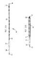
- FIG. 1Ais an end view of an embodiment of an impeller having three rows of blades (blade rows);
- FIG. 1Bis a perspective view of the impeller of FIG. 1A ;
- FIG. 2Ais a highly schematic side elevational view of an embodiment of an impeller according to the present invention in its deployed configuration
- FIG. 2Bis a highly schematic side elevational view of the impeller of FIG. 2A in its stored configuration
- FIG. 3is a highly schematic side elevational view schematically illustrating the deployment of the impeller of FIG. 2A ;
- FIG. 4Ais an enlarged perspective view of a portion of a blade having an embodiment of a winglet
- FIG. 4Bis a cross-sectional view of the blade of FIG. 4A within a portion of a vessel;
- FIGS. 5A-5Care cross-sectional views of blades having exemplary winglet configurations
- FIG. 5Dshows cross-sectional views of exemplary winglet edge geometries
- FIGS. 6A-6Dare end views of an impeller blade, further illustrating possible winglet configurations
- FIG. 7Ais an enlarged perspective view of a portion of an impeller according to the present invention having an indentation in the hub surrounding the proximate end of the blade;
- FIG. 7Bis a cross-sectional view of the portion of the impeller shown in FIG. 7A ;
- FIG. 8is a stress-strain graph for a polyurethane material used to form an impeller blade
- FIG. 9Ais a perspective view of an embodiment of an impeller in a stored configuration within a storage housing
- FIG. 9Bis a perspective view of the impeller of FIG. 9A after emergence from the storage housing;
- FIG. 10is a perspective view superimposing deployed and operational configurations of an embodiment of an impeller
- FIG. 11is a graph showing normalized average fluid shearing stresses as a function of normalized volume flow rates
- FIG. 12is a graph showing normalized average fluid shearing stresses as a function of tip gap sizes
- FIG. 13is a side view of another embodiment of an impeller according to the present invention.
- FIG. 14is a perspective view of a blood pump according to the present invention.
- FIG. 15Ais a side elevational view of the impeller portion of the blood pump of FIG. 14 ;
- FIG. 15Bis a side elevational view of a cannula in which the impeller of the blood pump of FIG. 14 operates;
- FIG. 15Cis a partial longitudinal cross-sectional view of the retainer sheath for use with the blood pump of FIG. 14 ;
- FIG. 16shows highly schematic side views of different mesh designs
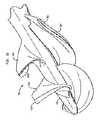
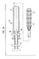
- FIG. 17is a perspective view of the expandable portion of the cannula shown in FIG. 14 in the deployed state
- FIG. 18is an enlarged perspective view of the discharge or proximal end of the expanded cannula having a hexagonal mesh
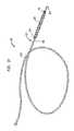
- FIG. 19is an enlarged perspective view of the inlet or distal end of the expanded cannula showing a guide wire having a distal tip;
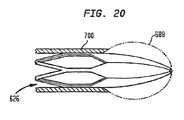
- FIG. 20is an enlarged longitudinal cross-sectional view of an alternate embodiment of the distal end of the cannula forming a dilator
- FIGS. 21A and 21Bare side elevational views of the expandable portion of the cannula in stored and deployed configurations, respectively;
- FIGS. 22A and 22Bare longitudinal highly schematic views of the blood pump of the present invention in the deployed and stored configurations, respectively, showing system components;
- FIG. 23Ais a longitudinal cross-sectional view of the blood pump of FIG. 14 in its deployed configuration
- FIG. 23Bis a longitudinal cross-sectional view of the blood pump of FIG. 14 in its retracted position
- FIG. 23Cis a side elevational view of a cannula in which the impeller of the blood pump of FIG. 14 operates;
- FIG. 24is a longitudinal cross-sectional view of an alternate embodiment of a blood pump in its deployed configuration
- FIG. 25is a side elevational view in partial cross-section showing a pre-parked sheath embodiment of the present invention.
- FIG. 26is a highly schematic view showing the blood pump deployment in a patient.
- An impellerincludes a hub, and at least one blade supported by the hub.
- the impellermay have a deployed configuration in which the blade extends away from the hub, and a stored configuration in which the impeller is radially compressed, for example by folding the blade towards the hub.
- the outer edge of a blademay have a winglet.
- the impelleralso may have a trench or indentation proximate to a blade root to facilitate folding of the blade and/or to reduce shear stresses in the fluid flow induced by rotation of the impeller.
- Impellersthat do not radially compress, but retain a generally constant configuration. Impellers according to the present invention may be used in various applications, including improved blood pumps.
- Impellers according to embodiments of the present inventionmay include a plurality of blades which may be arranged in one or more blade rows positioned along the impeller hub.
- FIGS. 1A and 1Billustrate end and side views, respectively, of an impeller 100 .
- the impellerincludes a hub 10 , and a plurality of blades 12 arranged in three blade rows.
- the first blade rowincludes blades 102 and 104
- the second blade rowincludes blades 106 and 108
- the third blade rowincludes blades 110 and 112 .
- Each blade rowmay include the same number of blades, for example, one to three blades. Alternatively, the number of blades in each blade row may differ. For embodiments in which there are more than two blade rows, the number of blades in at least one blade row may differ from the number of blades in other blade rows.
- the provision of a plurality of blade rowsfacilitates the achievement of larger values of fluid head or pressure rise than a single blade row, while allowing the impeller to be radially compressed while allowing into a stored configuration.
- impeller designprovides an impeller having a long helical blade exhibiting a significant degree of wrap around the central hub.
- the three-dimensional shape of long helical bladeslimits the degree to which they can be folded without breaking or permanently deforming.
- the individual bladesmay have an essentially two-dimensional shape which allows easier deformation during the storage process.
- the combination of two or more blade rowscan produce the same flow and pressure as a single helical blade of similar axial extent.
- individual bladesmay have a height-to-chord length ratio in the range of about 0.5-1.5, and a plurality of blade rows of such more easily folded blades may combine to provide a similar hydraulic efficiency as a longer serpentine blade.
- the use of a long serpentine blademay lead to separated flows, leading to thrombosis, which can be avoided using multiple blade rows.
- impellers according to some embodiments of the present inventionmay have multiple separate sets of blades, rather than a long, continuous helical blade.
- a continuous long helical bladeis difficult to fold up against the hub, and by splitting a long blade into two or three shorter sections, the blade can be more easily folded into a cylindrical volume or space and subsequently deployed when desired.
- An impeller according to the present inventionmay include at least two blades arranged about the circumference of the hub in a first blade row.
- the at least two bladesmay be positioned approximately 360/N° apart from one another about the circumference of the hub, where N represents the total number of blades in the first blade row.
- the impelleralternatively may include a plurality of blades arranged in at least two blade rows, with each blade row including at least two blades.
- the at least two blades in the first row of bladesmay be positioned 360/N 1 ° apart from one another about the circumference of the hub and the at least two blades in the second row of blades may be positioned 360/N 2 ° apart from one another about the circumference of the hub, where N1 represents the total number of blades in the first row and N 2 represents the total number of blades in the second row. N 1 and N 2 may be the same or different.
- the first and second rows of bladesmay be circumferentially offset relative to one another by 360/2N 1 °.
- the number of blade rowsis two or three.
- the blade rowsmay be interleaved (overlapping along the axial direction), which can increase performance but may increase the diameter of the impeller in the stored configuration. If blades are interleaved, they will tend to fold on each other in the stored configuration, increasing the stored diameter of the impeller.
- the blade rowsare preferably spaced apart along the hub, proximate to each other but not interleaved.
- the spacing between blade rowsmay be less than the axial extent of each blade row along the hub axis.
- a larger blade row spacingallows shear wakes to decay between blade rows, but lengthens the impeller, making it more difficult to move the impeller along a curved path, such as along blood vessels to a desired location within a patient.
- Blade rowsmay also be clocked relative to each other, the clocking being an angular displacement between corresponding blades of each blade row, and in particular, an angular displacement between the trailing edge of a blade in one row and the leading edge of the corresponding blade in the next row.
- an impellermay have at least a first blade row and a second blade row, the first and second blade rows including a similar number of blades.
- the blades of the first blade rowmay be angularly offset (clocked) relative to the corresponding blades of the second blade row. In blood pumping applications, the angular offset can be adjusted to reduce hemolysis.
- Bladesmay be clocked so that the leading edge of a following blade does not reside in the wake from a leading blade, and the clocking may be clockwise or counterclockwise to achieve this. Blade rows may be clocked relative to each other to avoid tandem blade effects, where the following blade resides wholly in the boundary layer or wake of the leading blade, so as to reduce shear stresses.
- the amount of lean or tilt of the bladesmay be adjusted according to the blade stiffness.
- the blade leanmay be a forward lean (toward the pressure face) of between about 30° and about 60°.
- a forward lean bladetends to deform so as to increase the angle of incidence of the fluid at the tip, and thus increase the load on the blades.
- Conventional propellersuse a backward lean blade which tends to unload the blade tip under structural deflection. Hence, the use of a forward lean is unusual.
- Forward lean of flexible bladesmay be used to minimize the gap between a blade tip and the inside surface of a conduit in which the impeller operates.
- a backward leanmay make it more difficult to control the size of the gap.
- the twist pitch angles of the bladesalso may be variable, for example for impeller operation in a conduit.
- the blade deviation anglemay be in the range about 15 to 30 degrees to assist impeller operation at low Reynolds number operation (for example, less than 50,000 for the blade tip chord) within a conduit, hence reducing hemolysis in blood pump applications.
- the pitch at the tipmeasured relative to a circumferential direction, can be appreciably less than the pitch at the root, to match slower fluid flow within a boundary layer near the inside surface of the conduit.
- the blade of an improved impeller for operation within a laminar flow profile within a cannulahas a blade twist, the pitch being approximately matched to the flow profile, the blade tip having a smaller pitch angle than the blade root.
- the blademay have a slightly humped appearance in a region of relatively rapid change in blade pitch.
- the twist in the blade pitchmay be in the opposite direction as any boundary layer will tend to be closer to the hub.
- the root of a serpentine bladeexhibits a geometric characteristic known as camber, the curvature of the airfoil section if laid out on a flat surface.
- camberthe curvature of the airfoil section if laid out on a flat surface.
- the camber of the resulting partial sectionscan be limited, for example to values of less than 10%, for example 5%. In the latter case, the deviation of any section from a straight line will be on the order of five percent of the section chord length.
- a serpentine blade having a camber of 15%may be divided into three sections, each of which will be substantially linear and more easily folded. The result would be an impeller having three blades, arranged in three blade rows, with performance similar to that of the serpentine blade.
- the wrap angle(from the leading edge to the trailing edge) can be limited to a maximum of about 30 degrees.
- blade rowsmay each contain substantially two-dimensional blades (compared with a single pumping efficiency), the blades serpentine blade of similar more readily folding against the hub than would a serpentine blade.
- the modulus of the bladesmay be lower for deforming the blades to the stored configuration of the impeller, which may correspond, for example, to strains of 100% 200%.
- the modulus for the larger blade deformations in the stored configurationmay be about ten times less than the modulus for operational stresses.
- the impellermay include blades formed from a material having a flexural modulus of about 10,000 psi for operational stresses and about 1,000 psi for storage deformations.
- FIG. 2Ashows an impeller 200 in a deployed configuration, the impeller including a hub 210 and a plurality of blades 212 .
- Impeller 200has a radius R 1 in the deployed configuration, as measured from the central longitudinal axis of hub 210 to the outermost blade tip. The deployed diameter is twice the deployed radius, and is the diameter of a circle described by the blade tip as impeller 200 rotates around the longitudinal axis of hub 210 .
- Impeller 200may be used as an axial pump, to pump fluid through conduit 250 .
- impeller 200may be used as a motive force provider for a vehicle.
- the impellermay power a boat, such as a jet-boat, or other water craft.
- conduit 250could be a tube immersed in the water surrounding the vehicle, or there may be no conduit at all.
- FIG. 2Bshows impeller 200 in a stored configuration, with blades 212 folded or otherwise deformed towards hub 210 and held in this stored configuration by a storage housing 260 .
- the radius R 2 of storage housing 260which in this case defines the stored diameter of impeller 200 , is appreciably less than the radius R 1 of the deployed impeller shown in FIG. 2A .
- a deformed impeller blade 212may contact the inside surface of storage housing 260 at one or more locations.
- the flexible blades 212 of impeller 200can be folded or otherwise radially compressed such that the maximum diameter of the impeller in the stored configuration is approximately half, or less than half, the diameter of the impeller in the deployed configuration. Referring to FIGS. 2A and 2B , this corresponds to R 2 ⁇ (R 1 / 2 ).
- a ratio of R 2 ⁇ (R 1 / 2 )is useful for blood pump applications, allowing a blood pump to deploy to a diameter of between about 6 millimeters and about 7 millimeters within a human body, while being non-surgically inserted with a diameter of between about 3 millimeters and about 4 millimeters. Other diameter ratios are useful for other applications.
- FIG. 3is a schematic view illustrating the deployment of impeller 200 .
- Impeller 200has hub 210 and blades 212 , and is retained in the stored configuration by storage housing 260 .
- Storage housing 260may be a tube in which impeller 200 is stored prior to deployment.
- a drive shaft 230is used to rotate impeller 200 .
- the figurealso shows an optional guide wire 280 within rotating drive shaft 230 which can be used to position impeller 200 at a desired location.
- the rotation of drive shaft 230may also assist in deploying impeller 200 , for example through twisting the impeller out of storage housing 260 if the inner surface of the storage housing has a threaded texture.
- conduit 250is shown into which impeller 200 is deployed for operation in its larger deployed configuration.
- Conduit 250may represent any structure through which a fluid may flow relative to impeller 200 , such as a tube, catheter, cannula, or body vessel such as a blood vessel.
- Impeller 200 contained within its storage housing 260may be deployed within a conduit, such as a utility pipe (water, gas, sewage, and the like), body vessel (such as a blood vessel), portion of a thrust unit for a vehicle, or other structure through which a fluid may flow.
- the impellercan be conveyed to a desired location within the conduit in a stored configuration, and then deployed to the deployed configuration.
- Impeller 200can be deployed by urging the impeller axially out of storage housing 260 , for example using drive shaft 230 attached to the impeller. The impeller then unfolds into the deployed configuration using the stored potential energy of blades 212 in the stored configuration.
- the stored configurationfacilitates conveyance of impeller 200 to the desired location, enabling it to be passed through openings which are smaller than the diameter of the impeller in the deployed configuration.
- the impellermay be radially compressed back into the stored configuration, for example by urging the impeller back into storage housing 260 , such as by re-folding flexible blades 212 against hub 210 .
- the stored impellermay then be removed from the use location through an access hole having a dimension less than the diameter of the impeller in the deployed configuration.
- impeller 200can be inserted in the stored configuration through a relatively small entrance hole into a conduit 250 of larger diameter.
- storage housing 260is described above as a tube from which impeller 200 may be deployed by axial movement out of the storage housing, that need not be the case. Rather, storage housing 260 may itself be expandable or have an expandable portion, as described below. Expansion of storage housing 260 would allow impeller 200 to deploy, such that the impeller would not need to be pushed axially out of the storage housing to achieve the deployed configuration. Thus, with reference to FIG. 3 , conduit 250 may represent storage housing 260 in an expanded condition.
- Impellers according to the present inventionmay include at least one blade having a winglet.
- all blades within a blade rowmay include such a winglet; other blades in the impeller mayor may not include a winglet.
- a wingletmay improve hydrodynamic performance of the impeller in the operating state, and may also reduce shear stresses that exist within the fluid being pumped. As a result, when the fluid being pumped includes biological structures such as cells, the degradation of such structures by the pumping action may be reduced.
- An impeller bladetypically has a pair of opposed faces: a pressure face inducing relative motion of the fluid through pressure as the blade rotates through the fluid; and a suction face inducing fluid motion by suction.
- the pressure and suction facesare not planar, but rather are curved in the same general direction to define an airfoil shape.
- the bladealso has a leading edge cutting through the fluid as the blade rotates, a trailing edge, and an outer edge (which may also be referred to as a blade tip or distal end of the blade).
- a wingletmay extend in the direction of motion of the impeller (from the pressure face of the blade), in the direction opposite the direction of motion (from the suction face of the blade), or in both directions.
- FIGS. 4A and 4Bshow perspective and cross-sectional views, respectively, of a blade 212 of impeller 200 having a winglet 222 at its distal end.
- FIG. 4Ashows the cross-section of the blade 212 where it joins winglet 222 as a dashed line, the winglet significantly enlarging the cross-section of the blade at its distal end.
- FIG. 4Bshows blade 212 and winglet 222 in cross-section, in which the winglet and blade form an approximate T-shape. As shown in FIG. 4B , the suction side of the blade is on the right, and the pressure side is on the left.
- winglet 222may have a width between about 1 and 3 times the distal thickness of the blade, measured in a direction parallel to the blade rotation direction. If blade 212 has a chord length, winglet 222 may have a length approximately equal to the chord length.
- Winglets 222are preferably aerodynamically smooth shapes having leading edges where flows impact the edges of the winglets, and trailing edges where flow is discharged from the winglet surfaces. Winglets 222 preferably have smooth aerodynamic cross-sections, generally in the direction of the mean flow, which is parallel to the flow direction along the blade tip surfaces.
- FIG. 5Dshows possible leading edge geometries, including a radius edge 240 , a sharp edge 242 , and chisel edges 244 and 246 .
- the distal end of blades 212 in the deployed configurationmay be located proximate to the interior surface of the conduit, so as to define a tip gap 255 between the blade distal end and the inner surface of the conduit.
- the tip gap 255may be about 10 to 50 percent of the maximum thickness of the distal end of the blade.
- appropriately shaping the tips of the bladessuch as by providing the tips with winglets 222 , can improve the quality of the flow field and reduce shear stresses.
- the winglet 222may be proximate to the inner surface of conduit 250 , a configuration which may be used as a hydraulic bearing for an impeller 200 .
- the tip shapemay be rounded to reduce hemolysis.
- a rounded blade tipreduces flow separation and turbulence at the tip compared with a squared-off tip, and winglets further reduce flow separation and hence turbulence in the wake of the blade tip as it moves relative to the fluid.
- the gap 255 between the tip of blade 212 and the inner surface of conduit 250may be increased while retaining the performance of an impeller having a smaller tip gap but no winglets. This effect is analogous to retained lift near the end of winglet-equipped airplane wings.
- Fluid head lossesare minimized for a tip gap in the range of about 0.10-0.15 times the maximum thickness of the distal end of the blade for blades without winglets, this range being expected to reduce hemolysis by reducing shear stresses in gap flows.
- Winglet-equipped bladesshow minimum fluid head losses at a tip gap of about 0.25-0.30 times the maximum thickness of the distal end of the blade.
- An increased tip gapreduces shear stresses for impeller operation in a conduit, and for blood pumping applications hemolysis is reduced compared with the use of a smaller tip gap.
- FIG. 5Ashows a suction side winglet 262 extending from the outer edge of the suction face of blade 212 . This is a view from the leading edge, in cross-section, so that the blade rotates towards the direction of viewing.
- FIG. 5Bshows a pressure side winglet 264 extending from the pressure face of blade 212 .
- the parametersmay be similar to the suction side winglet.
- the function of the pressure side wingletis to reduce flow through the gap 255 . There is less effect of creating a hydrodynamic bearing, but the pressure side winglet “scrapes” low momentum fluid off the inner surface of the conduit 250 and prevents this fluid from entering gap 255 and subsequently being used in the core of a tip vortex. This can reduce shearing stresses in the bulk of the fluid flow.
- FIG. 5Cillustrates a combined winglet 266 extending from the outer edge of both the pressure and suction faces of blade 212 .
- Embodiments of the present inventioninclude the configurations shown in FIGS. 5A-5C .
- Numerical methodscan be used to design the winglet configurations. Where the blade chord lengths are long and the blade has a significant helical extent, the geometry and shape of the blade tip and the winglet can become complex.
- FIGS. 6B-6Dfurther illustrate winglet configurations, the blade supporting the winglet retaining the same shape in these examples.
- FIG. 6Aillustrates the outer edge shape 270 of a blade 212 not having a winglet.
- FIG. 6Bshows a pressure side winglet extending from the outer edge of the pressure face of blade 212 , extending over portion 272 .
- the portion 270 of the wingletcorresponds to the original outer edge shape of the blade shown in FIG. 6A .
- FIG. 6Cshows a suction side winglet, the portion 274 extending from the outer edge of the suction face of the blade, and the portion 270 corresponding to the original outer edge shape of the blade.
- the pressure side of the bladewill have a radius of approximately 1 ⁇ 3 to 1 ⁇ 2 the blade thickness or width.
- the extent of the wingletmay be from 1 ⁇ 2 to 3 times the blade thickness.
- a thickness approximately equal to the blade thicknessis shown.
- the wingletis mostly positioned to the downstream half of the blade as shown. The purpose of this is to create a hydrodynamic bearing in which the outer face of the winglet is in close proximity to the inner surface of the conduit in which the blade is operating.
- Gap 255can be between about 10 percent and about 25 percent of the base blade maximum thickness, and is an area that is mostly parallel to the fluid conduit 250 . It can be a cylindrical, conical or curved side cylinder where the radius is a function of the axial position of the blade element. Parameters for pressure side winglets and combined winglets (described below) may be similar.
- FIG. 6Dshows a combined pressure side and suction side winglet extending from both the pressure face and the suction face of the blade, the portion 276 extending from the suction face, the portion 278 extending from the pressure face, and the portion 270 corresponding to the original outer edge shape of the blade.
- impeller 200may have one or more structural features which aid achievement of the stored configuration.
- Such structural featuresmay include one or more indentations proximate to the blade root to facilitate deformation of the blade into the stored configuration.
- An elongated indentationsuch as a trench 282 , may be formed in the hub 210 of impeller 200 proximate at least part of the proximal end of the blade (the blade root, where the blade joins the hub).
- Trench 282may be formed adjacent to one or both of the suction face and the pressure face of blade 212 .
- trench 282is formed in hub 210 parallel with and adjacent to the proximal end of the blade.
- the structural featuresmay facilitate movement of the distal end of blade 212 towards hub 210 .
- a trench 282 around some or all of the blade rootcan help reduce internal mechanical stresses in blade 212 when the blade is in the stored configuration, for example folded against hub 210 .
- blade 212may have a cross-section in the shape of an airfoil and the indentation may be a curved trench formed in the impeller hub 210 parallel to the proximal end of the blade.
- Other structural features which may aid achievement of the stored configurationinclude hinges (such as living hinges) with one or more indentations or cuts, not shown but known in the art, in the blade 212 and/or hub 210 ; forming a portion of impeller 200 proximate the blade root from a more easily deformable material; and the like.
- the indentationmay also be referred to as a “dillet,” and may include any undermining of the blade root.
- a dilletmay be a trench proximate the blade root, for example having a depth between about 0.5 and about 1.5 times the blade width, and/or a width of a similar size range.
- a dilletcan facilitate folding of the impeller blade towards the hub to achieve the stored configuration.
- the dilletmay also reduce fluid shear stress and flow vortices in a fluid moving relative to impeller 200 as the impeller operates. In blood pumping applications, lower shear stresses lead to reduced hemolysis of the blood.
- Hub 210may have dillets proximate both faces of blade 212 , one dillet facilitating folding of the blade (depending on the direction the blade is folded towards the hub), both dillets reducing the formation of a root junction vortex and hence reducing hemolysis in blood pumping applications.
- the dilletmay be a horseshoe dillet, for example approximating the shape of a horseshoe vortex that would otherwise form at the blade root.
- dilletsmay be provided to reduce shear stresses, even for impeller blades that are not folded.
- Impeller 200may be in the form of impeller body, including hub 210 and one or more a unitary blades 212 formed from a single material.
- blades 212 and hub 210may be formed from different materials.
- blades 212are flexible so that they can be deformed towards hub 210 in the stored configuration.
- Blades 212may be formed in any way that allows expansion from a stored configuration to a deployed configuration, the deployed diameter of impeller 200 being larger than its stored diameter.
- Blades 212may be formed from any material that permits the achievement of a stored configuration in which the blades are folded toward hub 210 .
- the bladesmay be formed from a rubbery, elastic or other material having sufficient resilience to expand when the blades are no longer held in the stored configuration, such as when impeller 200 is deployed from a storage housing.
- the bladesmay be formed from polymer materials, such as polyurethane or other polymers having suitable elasticity properties. For medical devices such as blood pumps, biocompatible polymers are preferred. The average molecular weight may be chosen within a given range to obtain desired properties.
- the bladesmay be formed from other flexible polymers, from expandable foam optionally with a skin, or from other compressible or deformable materials including shape-change or shape-memory materials, and metals.
- Blades 212may be formed with both a substantially rigid portion and a flexible portion, the blades being deformed towards hub 210 by deformation of the flexible portion.
- the flexible portionmay include a hinge, such as a living hinge, a narrowed region, a material which is different from the material of the rigid portion, or other configuration.
- Blades 212 and (optionally) hub 210may be constructed of a low modulus polymer, for example a low flexural modulus polyurethane (this term includes polyurethane ureas, which were used to form impellers according to the present invention).
- Impeller 200may be a unitary structure, with the blades and hub formed as one from the same material, for example by molding a polymer.
- blades 212may have a stiffness approximating that of a thick rubber band. In such embodiments, the blades will have some stiffness, but will deform under operating loads.
- the material forming impeller 200may be chosen so as to have a linear modulus at operational stresses, allowing predictable deformation of the blades under load, and a non-linear modulus at the higher stresses used to deform the blades into the stored configuration.
- Impeller 200may have blades 212 formed from a polymer, such as a polyurethane, having a flexural modulus (for operational stresses) between about 3,000 psi and about 30,000 psi, more preferably between about 5,000 psi and about 20,000 psi, and still more preferably between about 7,000 psi and about 10,000 psi.
- the modulus for operational stressescorresponds to deformations of the impeller during operation, which in some examples may correspond to strains of approximately 5%.
- the blade thicknessmay be reduced when using higher modulus materials to achieve the desired flexibility.
- Impeller blades 212may, for example, occupy as much as 95% of the compressed volume of impeller 200 when the impeller is in the stored configuration.
- FIG. 8is a stress-strain curve for a non-linear material that can be used to form impeller 200 according to the present invention.
- the left (low stress) filled circlecorresponds to an impeller operating point (stress and strain under operating conditions) and the right (high stress) filled circle corresponds to the impeller stored configuration.
- the stress/strain relationshipis approximately linear at the impeller operating point, so that deformations due to operational stresses can be accurately predicted by numerical modeling.
- the stored configurationin which blades 212 are folded against hub 210 , is within a high strain non-linear portion of the curve. This allows the stored configuration to be achieved without passing the material tensile failure point, and also reduces the stresses necessary to achieve the stored configuration.
- the maximum material elongation in the stored configurationis about 75 percent.
- a non-linear materialsuch as one having the characteristics of FIG. 8 , is used for blades 212 .
- Thisallows the blade material to be relatively stiff at operating loads, and relatively flexible at higher strains, such as when blades 212 are folded in the stored configuration.
- the strainmight be 1-10 percent at operating loads and 75 percent while folded, and the stress/strain curve may correspond to a higher modulus (e.g., 10,000 psi) at operating loads, and to a lower modulus (e.g., 1000 psi) at the higher loads associated with folding.
- the stress-strain curvemay have two approximately linear regions with a sharp change in slope between the operating point strain and the folded strain.
- Impellers 200may be fabricated from commercially available polyurethane polymers, for example having a modulus between about 5,000 psi and about 10,000 psi.
- Example impellers according to the present inventionwere fabricated as unitary bodies (including hub and blades) from elastomeric polymers.
- Example materials usedinclude ConathaneTM TU-901 (Cytec Industries, Inc., West Paterson, N.J.), which had a modulus of about 10,000 psi for operational deformations; ConathaneTM TU-701 (modulus of about 7,000 psi), and HapflexTM 560 (Hapco Inc, Hanover, Mass.), which had a modulus of about 5,000 psi.
- ConathaneTM TU-901Cytec Industries, Inc., West Paterson, N.J.
- ConathaneTM TU-701modulus of about 7,000 psi
- HapflexTM 560Hapco Inc, Hanover, Mass.
- a polymer impeller 200 retained in the stored configuration for excessive time periodsmay not properly deploy, for example due to creep or electrostatic welding between adjacent polymer surfaces.
- impeller 200is retained in the stored configuration only as long as necessary to insert the impeller to a desired location. Hydrodynamic stress and forward lean may be helpful both to deployment and overcoming any hysteresis effect.
- Impeller 200may deploy from the stored configuration due to stored potential energy associated with blade deformation towards hub 210 in the stored state.
- stored potential energymay be used (for example, using shape memory materials).
- external energymay be conveyed to impeller 200 , such as heat (for example, electrical heating of a wire or other structure), centrifugal forces, electromagnetic forces, gas jets, and the like to assist the deployment of the impeller.
- Impeller 200may be fabricated using molding, investment casting (for example, using a hard wax master), stereolithography, milling, or other techniques. Impellers 200 of the present invention have been fabricated using a flexible mold to avoid the presence of significant mold part lines.
- Very small impellersapproximately 6-7 mm in diameter in the deployed configuration, may be fabricated from a polymer (such as a polyurethane) and extracted from a precision mold. This allows production of impellers at very low cost.
- the flexible blades 212allow the impeller to be extracted from a mold without becoming mold-locked, and allow the use of one-piece molds, instead of multi-part or split molds. This can be advantageous for producing impellers designed for pumping bio-fluids.
- Blade shapescan be optimized using standard computational fluid dynamics analysis (CFD). If the impeller material is not flexible, there is no deformation of the impeller when rotating.
- An improved method of optimizing an impeller 200 formed of a flexible materialis to optimize the deployed configuration under operational stress (which may be termed the operational configuration).
- the impellercan be designed so that the operational configuration is optimized, which is not necessarily the same as the deployed configuration under no loading.
- a structural computationallows the determination of deformation under the load of operational stresses.
- impeller 200may have flexible blades 212 that deform into an optimized hydrodynamic shape when rotating and operating under design load conditions.
- the impeller blade 212can be designed so as to minimize destruction of delicate particles (such as emulsion droplets, suspensions, and the like) within a biological structures fluid.
- a CFD modelsuch as cells, may be used to simulate the through a intermediate be used to destruction shear stresses experienced by particles passing simulated impeller. Time integrations of shear stresses experienced by the particles may provide an estimated probability of cell in a biomedical application.
- a split blade designin which there are a plurality of blade rows such as discussed above, reduces the residence time in which cells remain in intermediate shear stress regions, allowing an advantageous reduction in cell or other particle destruction compared with a single long helical blade.
- the impeller blade(s) 212may deform during operation, and the optimum configuration of a blade may be achieved only upon deployment and rotation.
- the optimal, design configuration of blade 212may be achieved only with operational stresses.
- blade deformation in operationdue to flexibility of the blade, need not lead to reduced performance.
- Successful operationcan occur even when impeller 200 exhibits significant deflections from a manufactured shape.
- the impellercan be manufactured with allowance for the deflection included in the design.
- the configuration of an impeller operating at a predetermined rotation rate, or within a predetermined operating range,can be optimized.
- the operational configuration of the impellerincluding deformation due to operational stresses, is optimized.
- CFD optimizationmay be used to minimize flow velocity over blade surfaces (Reynolds number), vortex formation, flow jets, root junction flows, and to avoid formation of separated flows that may lead to thrombosis.
- An impeller 200 according to the present inventioncan operate in a low Reynolds number conduit flow, where the conduit boundary layer comprises a majority of the flow in the conduit.
- the Reynolds numberis the product of blade velocity and chord length, divided by the fluid viscosity.
- the Reynolds numbervaries with radius, and generally refers to the tip (distal end) of the blade unless otherwise stated.
- the Reynolds number for operation of a conventional propellermay be on the order of millions, so that there is a turbulent flow transition as the fluid passes over the blade.
- Impellers 200can be used with flows of small Reynolds number, less than 30,000 for the blade tip, for example the pumping of relatively viscous fluids at low velocity or flow rate.
- Impellers according to the present inventionmay operate with blade chord Reynolds numbers of between about 1,000 and about 30,000, preferably between about 2,000 and about 20,000, and more preferably between about 5,000 and about 20,000. The operation at such low Reynolds numbers corresponds to substantially laminar flow of the fluid over the blades. The reduced turbulence leads to reduced shear stress, and reduces hemolysis in blood pumping applications.
- Impellers 200may also be used for flows of larger Reynolds numbers, such as from 100,000 to several million. Impeller diameters can be in the range of several millimeters (or less) to several meters, depending on the application.
- impeller 200may be located within a fully developed laminar flow profile, for example at a distance of about 10-15 times the conduit diameter from the conduit inlet.
- a plurality of blade rowsmay be operated at a lower Reynolds number than a single longer serpentine blade having similar hydraulic efficiency.
- Each blade rowmay be separately optimized, for example to obtain substantially laminar flow.
- the blade rowsmay be clocked relative to one another to reduce hemolysis in blood pumping applications. Flow separations leading to thromboses may be avoided.
- each blade row-may include a different number of blades, for example 1, 2 or 3 blades.
- a plurality of blade rowsmay be used to reduce hemolysis in blood pumping applications compared to a single serpentine blade, while retaining similar or improved efficiency.
- axial headsmay be obtained similar to mixed flow pump heads.
- the blade chord Reynolds number of the first blade rowwas about 12,600, and was about 15,800 for the second blade row. This suggests that the flow was substantially laminar.
- the blades 212may not exhibit a transition to turbulent flow over the blade surface (where the shear stress suddenly jumps to a higher value), which for blood pump applications leads to lower hemolysis.
- Hemolysisrefers to the breakdown or destruction of red blood cells, releasing the hemoglobin contained therein.
- hemolysis for a given impeller 200can be estimated using equations known in the literature, and parameters discussed herein adjusted to reduce hemolysis.
- ⁇ ⁇ ⁇ Hb Hb ⁇ ( % )3.62 ⁇ 10 - 5 ⁇ t exp 0.785 ⁇ ⁇ 2.416 , there t is in seconds and ⁇ is in Pascals.
- variable ⁇is the scalar form of the stress tensor referred to as the Von Mises Criterion and is specified as:
- ⁇[ 1 2 ⁇ [ ( ⁇ 1 - ⁇ 2 ) 2 + ( ⁇ 2 - ⁇ 3 ) 2 + ( ⁇ 3 - ⁇ 1 ) 2 ] ] where ⁇ 1 , ⁇ 2 and ⁇ 3 are the principal stresses.
- NIH100 HbD
- Hbthe hemoglobin concentration in grams per liter
- MIH10 6 D.
- Garon and Farinasonly considered the hemolysis rate and only in laminar flow, and so the principal stresses are in reference to the laminar viscous stress tensor only. Garon and Farinas made no reference to how turbulent flow would be accommodated, but that discussion does take place in other research.
- Arvand et al.[“A Validated Computational Fluid Dynamics Model to Estimate Hemolysis in a Rotary Blood Pump,” Artificial Organs, 29(7):531-540 (2005)] actually advocated neglecting the Reynolds stress term in turbulent flow simulations in order to avoid “numerically caused variety” of the scalar form of the shear stress used in the hemolysis regression model, but the more conventional approach has been to use the effective shear stress (laminar plus Reynolds stress). See, for example, Gu et al., “Evaluation of Computational Models for Hemolysis Estimation,” ASAIO Journal , p. 202-207 (2005).
- Impeller 200may be stored in a storage housing, such as storage housing 260 , transported to a desired location in the stored configuration, and, once at the desired location, deployed into a deployed configuration. Rotation of the impeller then induces fluid flow at the location.
- the impeller in the stored configurationmay have a diameter approximately equal to or less than half the diameter of the impeller in the deployed configuration, the diameter of the stored configuration being generally defined by the inner diameter of the storage housing.
- the storage housingmay be any assembly which acts to hold the impeller in the stored configuration, and may comprise a tube, sleeve, or similar structure inside which the impeller is stored prior to deployment.
- blades 212may be folded in towards hub 210 , or otherwise deformed or reconfigured so as to present a reduced diameter compared with the deployed configuration. Impeller 200 may be held in the stored configuration by storage housing 260 . In the stored configuration, the distal ends of blade 212 are closer to hub 210 than in the deployed configuration, and the stored diameter of the impeller can be significantly less than its deployed diameter. Stored diameters of about one-half of the deployed diameter or less are achievable.
- the storage housingneed not have a fixed diameter, as does storage housing 260 , but may include a non-expandable portion, in which impeller 200 is stored, and an expandable portion, into which the impeller can be moved for deployment. Impeller 200 may then deploy within the expanded portion of the storage housing.
- the expandable portion of the storage housingmay also have a stored configuration. For example, the diameter of the expandable portion in the stored configuration may be approximately half or less of its diameter in the expanded state. Alternatively, the entirety of the storage housing may be expandable such that impeller 200 does not have to be moved axially for deployment.
- Impeller 200may be stored in a compressed configuration within the storage housing when the storage housing is retained in the compressed state. However, once the retainer sleeve is removed from that portion of the storage housing in which impeller 200 is located, the storage housing and impeller can expand to their expanded or deployed configurations. Impeller 200 may be deployed by urging the impeller blades 212 out of the confines of the storage housing, for example by pulling the retainer sleeve away from that portion of the storage housing overlying the impeller. In some embodiments, the retainer sleeve may be expanded in situ so as to allow impeller 200 to achieve the deployed configuration. Other methods of deploying impeller 200 will be clear to those skilled in the art.
- Impeller 200may be deployed by various methods.
- the storage housingmay be expandable so as to have an expanded configuration when impeller 200 is in the deployed configuration, and a compressed configuration when the impeller is in the stored configuration.
- the storage housingacts to radially compress impeller 200 in the stored configuration and allows the impeller to deploy when the storage housing expands.
- impeller 200may move axially out of the storage housing.
- FIG. 9Aillustrates an impeller 300 in a stored configuration, showing blades 332 and 334 and hub 310 . Blades 332 and 334 are kept folded against hub 310 by the housing 360 .
- FIG. 9Bshows impeller 300 pushed storage housing 360 and in the deployed configuration. Blades storage out of In the embodiment shown, impeller 300 has two rows of blades, as is seen more clearly in the deployed configuration, the first row including blades 332 and the second row including blades 334 .
- FIG. 10shows an impeller 400 including a hub 410 and a plurality of blades shown in both the deployed and operating configurations.
- the figureallows comparison of the deployed configuration under no load with the deployed configuration under operational stresses, when the impeller rotates at the operational rotation speed.
- the bladesassume a first shape indicated by reference numbers 462 A, 464 A and 466 A.
- the bladesWhen rotating in a fluid, the blades deform to an operational configuration indicated by reference numbers 462 B, 464 B and 466 B.
- Impeller 400may be designed so that the flexible blades deform into an optimized hydrodynamic shape when rotating and operating under design load conditions.
- the bladesdeflect forward as the lift on the blades is such that they create thrust, a force directed towards the left side of the figure, moving the blades toward the left side of the picture.
- the leading edge of the second blade rowis obscured.
- the first blade rowincludes blade 462 , shown in an operating configuration at 462 B and under a no load condition at 462 A.
- the leading edge of each bladetransitions smoothly into the trailing edge at the maximum blade radius.
- simulationsshowed that the hub also deflects slightly in a rotational manner, with the second blade row rotated at the root compared to the first blade row.
- FIGS. 11 and 12illustrate optimization for fluid shear stress for an example impeller having a design similar to impeller 400 shown in FIG. 10 .
- the distal ends of the impeller bladesmove proximate to the interior surface of a cylindrical conduit such that the tip gap between the blade distal end and the inner surface of the conduit is about 10 to 50 percent of the maximum thickness of the distal end of the blade.
- the curvesare double normalized, the design point values both being 1.0, the scales being read as percent of design flow and a factor times the value of stress at the design point.
- FIG. 11illustrates that at 70 percent of the design flow, the shear stress is 1.3 times the value at the design condition.
- FIG. 12shows that making the tip gap smaller than the design value makes the shear stress higher, whereas making the gap bigger than the design value reduces the shear stress by a smaller factor. Therefore, the fluid shear stress can be reduced to lower hemolysis in blood pumping applications, without significantly compromising pumping efficiency.
- FIG. 13illustrates an impeller 500 including a hub 510 , and two rows of blades having two blades each.
- the first rowincludes blades 582 and 584
- the second rowincludes blades 586 and 588 .
- Impeller 500has highly curved leading and trailing edge lines where the blade pitch angles are adjusted for local values of relative flow angle.
- Impeller 500was designed for operation inside a conduit, such as a cannula having a laminar flow profile, the flow rates being lower near the inside surface of the conduit.
- This illustrationshows the design elements of a low Reynolds number impeller for use in a left ventricular assist device (LVAD) in which the thickness of the boundary layer on the fluid conduit walls approaches the diameter of the conduit.
- the Reynolds number for a blood pump applicationwas determined to be in the range of 10,000-20,000.
- an expandable impelleris used together with a cannula which mayor may not have an expandable portion. If the impeller is not stored in an expandable portion, the impeller must be moved axially for expansion to its deployed configuration. If the impeller is stored in an expandable cannula or in an expandable portion of a cannula, the impeller expands into its deployed configuration with the expansion of the cannula.
- This combinationmay be used in improved blood pumps, such as an improved left ventricular assist device (LVAD).
- LVADleft ventricular assist device
- a cannulamay be provided that has expandable and non-expandable portions, and the impeller may be stored within, or proximate to, the non-expandable portion.
- the impellercan be urged out of the non-expandable portion of the cannula into an expanded portion of the cannula.
- the stored potential energy within the flexible blades of the impellerwould then induce self-deployment of the impeller, and the cannula may also self-expand through stored potential energy.
- the expanded cannulathen may have the role of a fluid conduit through which fluid flows when the impeller is rotated.
- An example of such systemis blood pump 600 described below.
- An expandable cannula and impellermay both be stored within a retainer sheath and deployed together when urged out of the retainer sheath, as is also described below.
- Impellers according to the present inventionmay be used for a variety of applications, including an axial pump for a fluid (gas or liquid), a motive force for a vehicle, or other applications.
- Applications of the improved impellers according to embodiments of the present inventioninclude pumps for chemical engineering, propellers for airborne or maritime vessels, water pumps, and the like.
- Impellers according to the present inventionmay be attached to one end of a flexible drive shaft. A torque applied to the other end of the drive shaft is then used to rotate the impeller. The torque may be applied by a rotating member, such as a motor.
- impellers according to the present inventionare well suited to blood pumping applications, including as a left ventricle assist device, as a right ventricle assist device, for pumping blood to other organs, and the like.
- the impellermay operate within the laminar flow profile of a cannula flow, so that the blade pitch preferably varies with radius to match the flow profile.
- An impeller with two blade rows, such as impeller 500 illustrated in FIG. 13feature in the second row blades that may have a groove-like takes a helical path from the leading edge to the trailing edge. This arises due to variations in the span wise loading, and allows an axial flow pump using this impeller to achieve a head rise similar to that of a mixed flow pump.
- the impellermay be compressed and packaged into a storage housing, such as a tube, cannula, or other structure, for insertion into an object.
- a storage housingsuch as a tube, cannula, or other structure
- the diameter of the storage housingcan be about three to four millimeters or less.
- the impellercan be deployed in situ into a geometry that may be about six to seven millimeters in diameter.
- the impellerthen can be rotated using a flexible drive shaft coupled to a drive motor external to the subject.
- Such impellersmay be capable of pumping 4 L/m (liters per minute), and more preferably 5 L/m or greater, for example in a left ventricular assist device (LVAD).
- the impellermay rotate at about 30,000 RPM.
- the impellermay include two or more airfoil shaped blades that form an axial flow pump, and may be positioned using a guide wire.
- the guide wiremay run within a hollow center of the flexible drive shaft, and the hollow center may also convey saline solution or other fluid for infusion, cooling and/or lubrication purposes.
- the guide wiremay be removed, if desired. Implantation into a living subject may be achieved without surgical intervention through an insertion cannula having a diameter of about 3-4 mm.
- a device including an impeller and a cannulamay be inserted in a stored configuration through an insertion cannula in the femoral artery, the impeller and cannula then deploying (expanding radially) to approximately twice the stored configuration diameter when located at a desired location, such as proximate to the aortic valve.
- a drive shaftcomprising a metal braid, a polymer braid or a composite material braid may be used, and the drive shaft diameter may be on the order of 11 ⁇ 2 to 2 millimeters, and may be hollow to allow the guide wire to pass therethrough.
- An impeller according to the present inventioncan be operated within a cannula, and a flow of 5 L/m at 100 mm Hg net pressure rise obtained (220 mm Hg across the impeller with pressure losses elsewhere). These parameters are well suited to blood pumping applications, for example within a left ventricular assist device (LVAD).
- LVADleft ventricular assist device
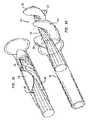
- FIG. 14A blood pump 600 for use in blood pumping applications, such as those noted above, is shown in FIG. 14 .
- Blood pump 600may be broken down into three main parts as shown in FIGS. 15A, 15B and 15C . It should be noted, however, that these features may be combined to produce devices according to the present invention that are intended for applications other than blood pumping applications.
- Impeller 605with a drive shaft 630 for implementing a rotational drive to the impeller.
- Impeller 605includes a hub 610 and a plurality of blades 612 , and may have any or all of the features of the impellers described above.
- Hub 610 and drive shaft 630may be hollow so as to define in blood pump 600 an internal lumen 670 .
- the second part, shown in FIG. 15Bis a housing or cannula 625 in which impeller 605 resides.
- Cannula 625has a storage housing 660 for impeller 605 when the impeller is in a compressed state.
- Storage housing 660may be nonexpandable.
- storage housing 660may itself be expandable or cannula 625 may have an expandable portion for housing the impeller when the impeller is in its operational or deployed configuration. Whether there is a difference in the location of impeller 605 in its operating and stored configurations depends on whether the impeller is moved axially within cannula 625 for deployment or whether cannula 625 expands in the area in which the impeller is stored.
- the third partis a retainer sheath 700 which holds at least a portion of cannula 625 in a compressed state for insertion into a vessel of a patient.
- a retainer sheath 700which holds at least a portion of cannula 625 in a compressed state for insertion into a vessel of a patient.
- the cannula 625 of blood pump 600has a nonexpandable portion 623 at its proximal end and an expandable portion 626 at its distal end.
- the expandable portion 626may be flared at one or both ends to aide in fluid flow.
- the nonexpandable portion 623 of cannula 625may be formed from conventional biocompatible polymer tubing and the like.
- the expandable portion 626 of cannula 625may be formed from a mesh 631 , such as a metal or polymer mesh, and an elastomer coating 633 .
- the meshpredominantly defines the radial stiffness and bending characteristics of the cannula, while the elastomer coats the mesh to form a continuous duct having a fluid-carrying capability.
- Mesh 631may be in the form of a hexagonal cell matrix, or may include circumferential rings 692 and axial connectors 694 , as shown in FIG. 16 .
- the circumferential ringspredominantly control the radial characteristics while the axial connectors affect axial stiffness and bending performance.
- Mesh 631may be formed from a flexible material, such as a polymer, metal, any shape memory material, or other material, and may include a machined metal cylinder with laser cut voids, a matrix of woven wires, or other configuration. Where mesh 631 is made from a memory metal alloy, such as nitinol, a constant diameter tube of the metal, having a metal thickness on the order of thousandths of an inch, for example, a thickness in the range of 0.005-0.007 inch, may be cut using a laser so as to leave a mesh structure.
- a memory metal alloysuch as nitinol
- a constant diameter tube of the metalhaving a metal thickness on the order of thousandths of an inch, for example, a thickness in the range of 0.005-0.007 inch, may be cut using a laser so as to leave a mesh structure.
- the constant-diameter meshmay then be expanded/contracted radially to the desired shape using a mandrel, and optionally a clamping mechanism may be used to ensure the mesh conforms to the mandrel geometry.
- the materialis “shape set” to this configuration using, for example, heat treatment.
- the mandrel, and hence the diameter profile of the expandable portion 626 of cannula 625optionally can be customized to a particular patient.
- mesh 631may be formed from a polymer.
- suitable materials for mesh 631include other metal s (such as alloys, including other memory metal alloys), polymers, other shape memory materials, and the like.
- An example cannula designmay include a bell-mouth inlet (to minimize hydrodynamic losses), a hydrodynamic diffuser at the outlet (for pressure recovery from fluid velocity), a screen-like device at the inlet end (for avoidance of inlet flow obstructions), and additional material at the screen tip that serves as a dilator when the cannula is contracted.
- a coatingsuch as elastomer coating 633
- the coating(which may be, for example, biocompatible, corrosion resistant and/or flow improving) may be formed by a solution casting method or by other techniques known in the art, including forming the coating as a separate tube, fitting it over the mesh and heat shrinking it to produce a tight fit.
- An elastic polymersuch as ElastaneTM or BiospanTM may be used for coating 633 , as may other polyurethanes, or other polymers.
- Mesh 631 and coating 633may provide a flexible, expandable portion 626 of cannula 625 that is a conduit for fluid flow.
- the expandable portion 626 of cannula 625may be generally cylindrical with a flow inlet 642 at its distal end and a flow outlet 644 at its proximal end.
- the mesh 631is radially expansible in a way which imparts a minimal length change (along the axial direction) during radial expansion/contraction.
- the expandable portion 626 of cannula 625may radially contract or expand using stored potential energy, and thus is preferably a self expanding/self-contracting device.
- the radial stiffness of the expandable portion 626is controllable via the mesh thickness and the geometric density of the cell structure, which can vary along the cannula length. Such variability is useful to match the cannula stiffness with the imposed hydrodynamic loading, enabling a nearly constant radial deflection of the tube when operating as a flow duct (wherein the hydrodynamic pressure varies along the length). This is important in the region of the impeller to provide a constant operational tip gap.
- Cannula bending stiffnessis also a controllable parameter that may vary axially.
- the bending stiffnessis predominantly controlled by the number and placement of the axial connectors, but also depends on the stiffness of the circumferential rings and the stiffness of the elastomer coating 633 .
- the relative placement of the circumferential ringslargely affects the radial stability of the cannula during bending.
- mesh 631may have a substantial amount of interleaving of adjacent circumferential rings. This configuration yields a very stable cannula with respect to radial buckling caused by a bending deflection.
- a mesh pattern with no interleavingyields a cannula that is prone to radial buckling during a bending deflection.
- Radial stiffnessmay be augmented via mesh thickness or mesh density.
- a dense meshexhibits greater radial stability than a less dense mesh.
- FIG. 17depicts cannula 625 in the expanded state.
- the expanded portion 626 of cannula 625includes a distal end 646 having an inlet 642 through which blood enters the cannula, and a proximal end 648 having an outlet 644 through which blood leaves the cannula.
- the portion between inlet 642 and outlet 644is the expandable portion 626 of cannula 625 .
- Inlet 642may be provided with a plurality of inlet struts 652 which prevent obstructions from entering the cannula.
- outlet 644may be provided with a plurality of discharge struts 654 which act as stationary stator blades and remove swirl velocity from the discharge flow of impeller 605 .
- Inlet struts 652 and discharge struts 654may occupy a short section of the cannula assembly (such as 1 cm) and may be flat linear elements arranged in a uniform circular disposition about the central axis of the device or may be part of mesh 631 . Alternatively, struts 654 may be formed with airfoil type cross-sections.
- Impeller 605is located close to the proximal end 648 , and a guide wire 680 extends through cannula 625 and through hub 610 of impeller 605 .
- the blood flow through the expanded portion 626 of cannula 625is from right to left (as shown in FIG. 17 ) for an LVAD, blood entering the device through the distal end 646 and leaving the device through the proximal end 648 .
- An uncut region of the original tuberetains the original tube diameter and may be used as the storage housing 660 in the form of a cup for retaining impeller 605 in the stored configuration.
- Storage housing 660may be referred to as a non-expanded portion of cannula 625 through which blood does not flow.
- the expandable portion 626 of cannula 625is attached to storage housing 660 through the discharge struts 654 .
- the cannula mesh 631 , discharge struts 654 and storage housing 660may be formed from a single tube formed from the same The cannula inlet struts 652 tube.
- the cannulacan and also be various attached components can be manufactured from a single piece of tube, for example from a nitinol tube using laser cutting, with a mandrel used for shaping the mesh portion.
- various portions of the cannulacan be manufactured separately and attached together using welding or other attachment techniques.
- Storage housing 660may have a flared end 649 which may be defined by the shape of discharge struts 654 to aid in moving impeller 605 back to its stored position.
- Impeller 605may be held in storage housing 660 in the stored configuration and moved axially into expandable portion 626 for deployment, such as by using drive shaft 630 to urge the impeller out of the storage housing. Impeller 605 then unfolds into the deployed configuration using the stored potential energy of blades 612 in the stored configuration. Alternatively, impeller 605 may be held in the stored configuration in the expandable portion 626 while contracted, and may deploy automatically upon expansion of the expandable portion. In still other embodiments, storage housing 660 itself may be expandable, allowing impeller 605 to expand to its deployed diameter without axial movement.
- the expandable portion 626 thereofwas formed from a nitinol tube having an inner diameter of 2.62 mm, an outer diameter of 3.02 mm, and a length of 150 mm. In the expanded state, portion 626 had a nominal inner diameter of 6.6 mm in the expanded section, and a nominal length of 133 mm.
- the expandable portionincluded 35 circumferential rings 692 , four axial connectors 694 per ring in a fully connected region (involving eight circumferential rings), and one axial connector 694 per ring in a minimally connected circumferential rings).
- Each region(involving twenty-eight circumferential ring 692 had four waves per ring, with a wave amplitude of 5.05 mm (at cut diameter).
- the typical thickness of inlet struts 652 and discharge struts 654was 0.2 mm.
- a rotatable drive shaft 630provides rotational coupling between a motor (not shown), located outside of the patient, and the impeller 605 .
- Drive shaft 630may have a substantially rigid portion 632 at its distal end which is connected to impeller 605 , and a substantially flexible portion 634 .
- the flexible portion 634 of the drive shaftmay be housed within a flexible tube 638 which supports the flexible portion and maintains its shape as it is driven rotationally.
- the proximal end of drive shaft 630may be connected to the motor for rotating the drive shaft and with it impeller 605 .
- drive shaft 630may be omitted, and the electric power may be provided through a proximal portion of the assembly to operate a pump motor and impeller 605 .
- Drive shaft 630may have a diameter on the order of 11 ⁇ 2 to 2 mm, and may be hollow to allow guide wire 680 to pass therethrough.
- the flexible portion 634 of drive shaft 630may be formed from a metal or polymer braid which is easily bendable so as to achieve a bend radius on the order of 1 cm.
- Commercially available flexible impeller drive shaftsmay be used in blood pump 600 , such as those formed from metal wire construction.
- heating problems due to friction between rotating and non-rotating componentsmay occur within any small radius bends required for operation.
- a composite flexible shaftmay be used to reduce such heating problems.
- the heating problemalso can be addressed by providing lubricating or low-friction films on one or both of adjacent surfaces with high relative rotational motion.
- a preferred drive shaft 630may be constructed from coiled stainless steel, with an optional polymer support tube.
- a particularly preferred polymeris polytetrafluorethylene.
- the rigid portion 632 of drive shaft 630may be supported by one or more bearings 672 retained in a bearing housing 675 .
- a saline solutionmay be directed into bearing housing 675 through internal lumen 670 , and the bearing unit end seal 674 may be dimensioned so that a of clean saline solution is infused (approximately 1-2 cc/hr).
- This fluid very small quantity into the patient flowhelps clean impeller 605 and dampens drive shaft vibrations.
- the fluid flowmay also prevent blood from entering bearing housing 675 and compromising its operation and life. If the density of drive shaft 630 is approximately the same as that of the saline solution or other introduced fluid, most of the vibration can be damped.
- Drive shaft 630may be formed from carbon or other fiber and polymer composite which has a lower density than metal and more closely matches the density of the saline solution. Other lower density draft shafts and/or higher density fluids may be used for vibration damping.
- the saline solution or other fluidmay be introduced to bearing housing 675 through openings 678 in hollow drive shaft 630 .
- FIGS. 23A and 23Bshow an embodiment of blood pump 600 having an axially slidable storage housing 660 .
- bearing housing 675may have a reduced diameter portion 677 between its ends housing bearings 672 .
- This reduced diameter portionthus defines a longitudinal space for sliding movement of an internal rib 662 defined by an indented annular channel 664 in storage housing 660 .
- storage housing 660has been moved proximally by the maximum extent permitted by the engagement of internal rib 662 with a proximal shoulder of bearing housing 675 , thereby revealing blades 612 of impeller 605 for deployment.
- FIG. 23Ashows an embodiment of blood pump 600 having an axially slidable storage housing 660 .
- bearing housing 675may have a reduced diameter portion 677 between its ends housing bearings 672 .
- This reduced diameter portionthus defines a longitudinal space for sliding movement of an internal rib 662 defined by an indented annular channel 664 in storage housing 660 .
- FIG. 23Astorage housing
- storage housing 660has been moved distally to the maximum extent permitted by internal rib 662 contacting a distal shoulder of bearing housing 675 . In this position, the distal end of storage housing 660 surrounds blades 612 of impeller 605 , retaining them in the stored configuration.
- the internal lumen 670 of blood pump 600receives guide wire 680 .
- Guide wire 680may have a two-part structure to assist in threading the guide wire through the bearing/seal assembly and through the hub 610 of impeller 605 , since part of that threading may be accomplished under factory controlled conditions, rather than at the time of use.
- guide wire 680may have a J-tip 682 which facilitates navigation of the tortuous arterial pathway from the femoral insertion site to the cardiac left ventricle chamber.
- Guide wire 680may include an optional device on its proximal end to allow the attachment of a similar diameter extension of the guide wire, residing in the collapsed cannula 625 .
- the lumen 670 in blood pump 600may have a relatively large diameter relative to the diameter of guide wire 680 .
- Guide wire 680may have one or more additional distal end features such as a spherical shape, or a valve plug 689 to plug a hole in impeller 605 after withdrawal of the guide wire (see FIG. 22A ).
- the guide wire channel extending through impeller 605 and the bearing unit end seal 674may have a valve action, as is known in the art, sealing the guide wire passage after removal of guide wire 680 .
- Guide wire 680may leave a mechanical seal, not shown, upon removal, or the material of impeller 605 may be designed so as to close the opening into lumen 670 upon removal of the guide wire. This avoids excess saline infusion into the patient.
- Blood pump 600may be inserted into the patient's body using a sheathless insertion procedure.
- Such proceduremay employ a retainer sheath 700 having a distal portion 702 and a proximal portion 704 , as shown in FIG. 15C .
- Distal portion 702may be about 20 cm in length, and have an inner diameter of about 9 fr (3.0 mm) and an outer diameter of about 10.5 fr (3.5 mm). The inner diameter of the distal portion allows storage of the collapsed cannula/impeller assembly.
- the proximal portion 704 of retainer sheathmay be about 1 meter in length with an outer diameter of about 9 fr. This proximal portion 704 may serve as the housing for the flexible portion 634 of drive shaft 630 and for the non-expandable portion 623 of cannula 625 .
- a “pre-parked” integrated insertion sheath 800may slide over the proximal portion 704 of retainer sheath 700 .
- the outer diameter of insertion sheath 800is preferably about the same as the outer diameter of the distal portion 702 of retainer sheath 700 , in this example about 10.5 fr.
- a smooth transitionis evident, as shown in FIG. 25 .
- the combined retainer sheath 700 and insertion sheath 800may be inserted into the patient's femoral artery as a single entity.
- the proximal portion 704 of retainer sheath 700may be pushed into the patient, pushing the distal end of the retainer sheath and its contents into the patient's left ventricle.
- the most distal end 710 of retainer sheath 700may have a series of slots (not shown) that allow slight expansion of the retainer sheath distal end during removal of cannula 625 .
- the funnel shape created by these slots and the subsequent bending of the material of the sheathfacilitates the collapse of the expandable portion of the cannula.
- Alternate meansmay be provided to facilitate the recollapse of the expandable portion 626 of cannula 625 .
- the drive motorrotates drive shaft 630 without rotating cannula 625 or retainer sheath 700 .
- the operation of blood pump 600is controlled and monitored by a control unit (not shown) which displays status and controls various functions.
- Sensorssuch as a pressure sensor and a flow rate sensor, may be affixed to various regions of the patient and/or blood pump 600 .
- the control unitpreferably displays rpm of the drive motor, patient blood pressures, blood flow rate, information as to the location of the blood pump in the left ventricle, saline infusion and discharge rates, saline infusion temperature, etc.
- a filtermay also be provided to show the presence of debris or blood in the saline discharge stream. The heart rate and blood flow rate are useful to be able to reduce patient dependency on the machine during recovery.
- Blood pump 600may be percutaneously inserted through the femoral artery and threaded toward the heart for use, for example, as a left ventricular assist device. Blood pump 600 may be inserted into a patient using conventional cannula insertion methods. The impeller 605 of the device is then expandable in situ to enable an increased blood pumping capacity compared to conventional non-expandable devices. This can eliminate the requirement for surgical intervention.
- Insertionmay be accomplished using the Seldinger technique which is well known in the art and used daily by surgeons and interventional cardiologists.
- an introducer needle(not show) is inserted into the femoral artery and used to introduce guide wire 680 . Once guide wire 680 is in place, the needle is withdrawn.
- An optional predilator(not shown) can be used over guide wire 680 to open up the arteriotomy (an opening in the femoral artery) to a size appropriate for insertion of blood pump 600 .
- a guide wire extension 685(see FIG. 26 ) contained within the collapsed cannula 625 may be attached to the attachment device at the proximal end of guide wire 680 .
- the entire assemblyis moved along the guide wire through the femoral artery opening previously created.
- the attachment of guide wire 680 to the guide wire extension 685enters the body of the collapsed cannula assembly.
- the distal end of the devicemay be provided with a tapered distal end dilator 688 , shown in FIGS. 20 and 22 . This may be a compressed form of the inlet 642 of cannula 626 in which the inlet struts 652 fold down into a tapered, closed configuration similar in profile to a conventional dilator tip.
- the blood pump 600in its collapsed state, is then threaded over guide wire 680 and inserted into the artery. Once blood pump 600 is positioned, guide wire 680 may be removed. A nose bearing or seal at the distal end of impeller 605 can then seal the guide wire opening through the hub 610 of the impeller. This allows saline solution to be injected into impeller 605 for cooling and lubrication purposes, as well as to prevent blood from entering the lumen 670 of blood pump 600 .
- the expandable portion 626 of cannula 625 and impeller 605are collapsed and may be contained within retainer sheath 700 .
- the proximal end 704 of retainer sheath 700may include an optional second integrated insertion sheath 800 which replaces the function of the separate introducer sheath when the device is positioned in place. If there is no “introducer” sheath present during the insertion of the assist device into the femoral artery, the process is referred to as sheathless insertion.
- FIG. 25a smooth transition from the diameter of insertion sheath 800 to the maximum diameter of retainer sheath 700 is shown.
- the transition regionhas effectively zero length and zero change in outer diameter.
- the transition regionis the region where the enlarged distal portion 702 of retainer sheath 700 meets the end 802 of insertion sheath 800 .
- the medical practitionerholds the exterior of insertion sheath 800 stationary and continues to push the retainer sheath assembly along guide wire 680 , until the distal end of the collapsed cannula and retainer sheath reside at the distal end of the guide wire, within the left ventricle cavity 900 .
- FIG. 26A possible location of the device for LVAD use is shown in FIG. 26 .
- the non-expandable portion 623 of cannula 625extends from the descending aorta 905 and into the femoral artery, from which it exits the host body.
- Guide wire 680may be advanced into the left ventricle 900 using an optional guiding catheter (not shown), and a fluoroscope may be used to establish proper positioning of the assist device.
- retainer sheath 700may be retracted, by a dimension of about 15 cm for some embodiments, allowing the expandable portion 626 of cannula 625 to expand to the deployed configuration.
- the final step in deploying blood pump 600involves pushing impeller 605 from its stored position within storage housing 660 and positioning it at a specified location within the expanded portion 626 of cannula 625 . This may be accomplished by applying a small force to drive shaft 630 while holding retainer sheath 700 at a fixed location. Retainer sheath 700 , in turn, holds the expanded portion 626 of cannula 625 at a previously fixed location. Once no longer restrained by storage housing 660 , impeller 605 expands to the deployed configuration due to the action of stored strain energy.
- the expandable portion 626 of cannula 625may attain its deployed configuration through the action of stored strain energy (potential energy). This process reveals the cannula inlet 642 , the expanded portion 626 of the cannula and the cannula outlet 644 .
- Successful operationrequires that the cannula inlet 642 reside in the left ventricle 900 of the heart and that the outlet 644 reside in the aorta.
- a fluid sealmust exist where the cannula is proximate to the aortic valve, and the surface smoothness of the cannula is preferably such that clinically significant abrasion of the aortic valve is prevented.
- distal end struts 652form an inlet grid which prevents the inlet from becoming blocked by soft tissues within the left ventricle.
- Impeller 605may be moved toward the distal end of cannula 625 which curves around through a valve into the left ventricle 900 of the heart, while the flexible portion 634 of drive shaft 630 , coupled to impeller 605 , extends outside of the body of the patient and is rotated by a drive motor.
- the non-expanded portion 623 of cannula 625similarly extends through the femoral artery and outside of the patient.
- the inlet 642 and struts 652 at the distal end of cannula portion 626allow substantially unrestricted flow of blood into the device, where it is driven by impeller 605 outside of the device through a discharge mesh or struts 654 at the proximal end 648 of cannula portion 626 .
- impeller 605may be used.
- One possible alternative approachmay include infusing a liquid or gas through a shaft to inflate impeller 605 .
- Another approachmay use rotational forces to induce blades 612 to form a desired shape.
- the potential energy in the blades, particularly in the blade roots,may be used to deploy the blades into their unstrained position, and hydrodynamic forces may cause the blades to further deform into their operating configuration.
- the retainer sheath 700serves to fix the position of the entire assembly within the patient. Blood pump 600 is now deployed and ready for connection to supporting equipment and use.
- impeller 605When the patient recovers and can be weaned from the necessity of using blood pump intervention, impeller 605 may be pulled back into an inactive compressed configuration in storage housing 660 or in a non-expandable portion 623 of cannula 625 , and the expandable portion 626 of the cannula may be pulled into retainer sheath 700 .
- Slots(not shown) or an outward flare 649 (see FIG. 9 ) may be provided at the distal end of storage housing 660 to assist in retraction of cannula 625 .
- Retainer sheath 700may then be pulled into proximity with insertion sheath 800 , and the insertion sheath, retainer sheath and cannula within it may be removed from the patient through the original femoral artery site. Subsequently, the wound in the patient may be closed in a conventional fashion.
- the flow rate and pressure rise of blood pumped by blood pump 600is greater than current non-collapsible devices of the same diameter, and the rate of blood damage (hemolysis) is maintained at a clinically acceptable low level.
- the use of the device as an RVADis similar to that described above.
- the expansion feature of blood pump 600is an advantage over non-expandable prior art devices. If the device were non-expandable, the maximum cross-section would be limited to approximately 3 mm to allow for percutaneous insertion. However, this cross-section is insufficient to achieve sufficient blood flow to maintain the health of the patient.
- Other applications of the device according to the present inventioninclude providing additional blood flow to other organs, assisting the heart during operations, and the like.
- the expandable portion 626 of cannula 625may be expanded by any desired method.
- mesh 631may expand in a radial direction when the expandable portion 626 is contracted along an axial direction, for example using a mesh 631 having a hexagonal structure.
- the expandable portion 626 of cannula 625can be shortened in the axial direction, providing radial expansion into the expanded state.
- the cannulawill achieve its expanded state as the shape memory material reaches a predetermined temperature, such as when the cannula is inserted into a patient I s blood vessel.
- a predetermined temperaturesuch as when the cannula is inserted into a patient I s blood vessel.
- Both impeller 605 and cannula 625 in their stored configurationsmay be held within retainer sheath 700 , whereby both may be mechanically deployed or may self-deploy when removed from the retainer sheath.
- Cannula 625may have at least two configurations, including a stored configuration and an expanded (deployed) configuration. When used as part of a blood pump, cannula 625 in the deployed configuration may be about 20-30 cm long with a diameter of about 6-7 mm. In the stored configuration, cannula 625 may have a diameter of about 3 mm, allowing nonsurgical insertion of blood pump 600 into a human subject through a femoral artery. The larger deployed diameter allows for higher fluid flow rates after insertion, and reduced friction pressure losses compared with a non-surgically inserted blood pump having a non-expandable cannula.
- An improved process for blood pumping within a living subjectincludes providing an expandable impeller, inserting the impeller into a patient in a stored configuration (for example, with a diameter of between about 3 mm and about 4 mm), positioning the impeller at a desired location within a blood vessel of the patient, deploying the impeller (for example, to a diameter of between about 6 mm and about 7 mm), and operating the impeller in an operating configuration at a Reynolds number of between about 1,000 and about 30,000, and preferably between about 2,000 and about 10,000. Higher Reynolds number operation and more efficient pump operation may be possible with higher rotation speeds, but may increase the destruction of structures within the pumped fluid, such as blood cells.
- the operating diameter of the impellermay be at least about 50% greater than the stored diameter. In other examples, the operating diameter may be at least about 100% greater than the stored diameter.
- componentsmay be scaled according to the size of the animal.
- Novel configurations and material choiceallow the improved device to be compressed for cannula insertion into a patient.
- Representative devicesinclude an expandable impeller, and a cannula that is at least in part expandable, inside of which the impeller rotates. Both the expandable impeller and the cannula have stored states that allow cannula insertion into a vein or artery using non-surgical methods. After insertion and location of the device, the expandable impeller and cannula expand into deployed states.
- the impellercan be driven through a flexible drive shaft from a drive motor external to the host, or using a motor proximate to the impeller, possibly integrated with a bearing system.
- inventions described hereinare not limited to ventricular assist devices.
- the improved cannula and impeller designsare useful for any application where a stored configuration having reduced diameter is useful for locating the pump at a desired location.
- a fluid pump operating undergroundmay be introduced into a pipe, channel, or cavity through an opening of lesser diameter, and operate at a diameter greater than that of the opening used.
- Applications of an impeller deploying within an expandable cannulainclude a collapsible fire hose with an integral booster pump, a collapsible propeller, a biomedical pump for a biological a fluid, and the like.
- impellersmay also be formed from metal sheets, plastic and non-resilient materials, for example in foldable configurations.
- Deploymentmay include the use of motors or other mechanical devices to unfold blades, automatic deployment induced by centrifugal forces, and the like.
Landscapes
- Health & Medical Sciences (AREA)
- Engineering & Computer Science (AREA)
- Heart & Thoracic Surgery (AREA)
- Mechanical Engineering (AREA)
- Cardiology (AREA)
- Hematology (AREA)
- Public Health (AREA)
- Biomedical Technology (AREA)
- Veterinary Medicine (AREA)
- Life Sciences & Earth Sciences (AREA)
- Animal Behavior & Ethology (AREA)
- General Health & Medical Sciences (AREA)
- Anesthesiology (AREA)
- General Engineering & Computer Science (AREA)
- Vascular Medicine (AREA)
- Physics & Mathematics (AREA)
- Fluid Mechanics (AREA)
- External Artificial Organs (AREA)
- Structures Of Non-Positive Displacement Pumps (AREA)
Abstract
Description
and for Hb-release by red blood cells:
there t is in seconds and τ is in Pascals. The Garon and Farinas model, in short, provides a framework for any damage model of the form
D=γtexpβτα
by calculating the net flux of the parameter through a volume.
So
where σ1, σ2and σ3are the principal stresses.
NIH=100HbD,
where Hb is the hemoglobin concentration in grams per liter, and the modified index of hemolysis (in parts per million) is:
MIH=106D.
PlA=PlD,
where both PI and PIA are platelet concentrations, for example in thousands per microliter.
Claims (26)
Priority Applications (5)
| Application Number | Priority Date | Filing Date | Title |
|---|---|---|---|
| US15/176,620US9717833B2 (en) | 2004-09-17 | 2016-06-08 | Heart assist device with expandable impeller pump |
| US15/633,189US10149932B2 (en) | 2006-03-23 | 2017-06-26 | Heart assist device with expandable impeller pump |
| US16/181,963US10864309B2 (en) | 2006-03-23 | 2018-11-06 | Heart assist device with expandable impeller pump |
| US17/084,896US11708833B2 (en) | 2006-03-23 | 2020-10-30 | Heart assist device with expandable impeller pump |
| US18/047,876US12404858B2 (en) | 2006-03-23 | 2022-10-19 | Catheter blood pump heart assist device |
Applications Claiming Priority (8)
| Application Number | Priority Date | Filing Date | Title |
|---|---|---|---|
| US61093804P | 2004-09-17 | 2004-09-17 | |
| US11/227,277US7393181B2 (en) | 2004-09-17 | 2005-09-15 | Expandable impeller pump |
| US78553106P | 2006-03-23 | 2006-03-23 | |
| US78529906P | 2006-03-23 | 2006-03-23 | |
| US11/728,051US7841976B2 (en) | 2006-03-23 | 2007-03-23 | Heart assist device with expandable impeller pump |
| US12/945,594US9364592B2 (en) | 2004-09-17 | 2010-11-12 | Heart assist device with expandable impeller pump |
| US13/618,071US9364593B2 (en) | 2004-09-17 | 2012-09-14 | Heart assist device with expandable impeller pump |
| US15/176,620US9717833B2 (en) | 2004-09-17 | 2016-06-08 | Heart assist device with expandable impeller pump |
Related Parent Applications (1)
| Application Number | Title | Priority Date | Filing Date |
|---|---|---|---|
| US13/618,071ContinuationUS9364593B2 (en) | 2004-09-17 | 2012-09-14 | Heart assist device with expandable impeller pump |
Related Child Applications (1)
| Application Number | Title | Priority Date | Filing Date |
|---|---|---|---|
| US15/633,189ContinuationUS10149932B2 (en) | 2006-03-23 | 2017-06-26 | Heart assist device with expandable impeller pump |
Publications (2)
| Publication Number | Publication Date |
|---|---|
| US20160354525A1 US20160354525A1 (en) | 2016-12-08 |
| US9717833B2true US9717833B2 (en) | 2017-08-01 |
Family
ID=38541699
Family Applications (8)
| Application Number | Title | Priority Date | Filing Date |
|---|---|---|---|
| US11/728,051Active2029-05-04US7841976B2 (en) | 2004-09-17 | 2007-03-23 | Heart assist device with expandable impeller pump |
| US12/945,594ActiveUS9364592B2 (en) | 2004-09-17 | 2010-11-12 | Heart assist device with expandable impeller pump |
| US13/618,071ActiveUS9364593B2 (en) | 2004-09-17 | 2012-09-14 | Heart assist device with expandable impeller pump |
| US15/176,620ActiveUS9717833B2 (en) | 2004-09-17 | 2016-06-08 | Heart assist device with expandable impeller pump |
| US15/633,189ActiveUS10149932B2 (en) | 2006-03-23 | 2017-06-26 | Heart assist device with expandable impeller pump |
| US16/181,963Active2027-07-15US10864309B2 (en) | 2006-03-23 | 2018-11-06 | Heart assist device with expandable impeller pump |
| US17/084,896Active2027-10-26US11708833B2 (en) | 2006-03-23 | 2020-10-30 | Heart assist device with expandable impeller pump |
| US18/047,876Active2027-08-31US12404858B2 (en) | 2006-03-23 | 2022-10-19 | Catheter blood pump heart assist device |
Family Applications Before (3)
| Application Number | Title | Priority Date | Filing Date |
|---|---|---|---|
| US11/728,051Active2029-05-04US7841976B2 (en) | 2004-09-17 | 2007-03-23 | Heart assist device with expandable impeller pump |
| US12/945,594ActiveUS9364592B2 (en) | 2004-09-17 | 2010-11-12 | Heart assist device with expandable impeller pump |
| US13/618,071ActiveUS9364593B2 (en) | 2004-09-17 | 2012-09-14 | Heart assist device with expandable impeller pump |
Family Applications After (4)
| Application Number | Title | Priority Date | Filing Date |
|---|---|---|---|
| US15/633,189ActiveUS10149932B2 (en) | 2006-03-23 | 2017-06-26 | Heart assist device with expandable impeller pump |
| US16/181,963Active2027-07-15US10864309B2 (en) | 2006-03-23 | 2018-11-06 | Heart assist device with expandable impeller pump |
| US17/084,896Active2027-10-26US11708833B2 (en) | 2006-03-23 | 2020-10-30 | Heart assist device with expandable impeller pump |
| US18/047,876Active2027-08-31US12404858B2 (en) | 2006-03-23 | 2022-10-19 | Catheter blood pump heart assist device |
Country Status (7)
| Country | Link |
|---|---|
| US (8) | US7841976B2 (en) |
| EP (4) | EP3115070B8 (en) |
| JP (3) | JP2009530041A (en) |
| CN (2) | CN102380135A (en) |
| AU (1) | AU2007230945B2 (en) |
| CA (1) | CA2646277C (en) |
| WO (1) | WO2007112033A2 (en) |
Cited By (31)
| Publication number | Priority date | Publication date | Assignee | Title |
|---|---|---|---|---|
| US20140341726A1 (en)* | 2013-05-14 | 2014-11-20 | Heartware, Inc. | Blood pump with separate mixed-flow and axial-flow impeller stages and multi-stage stators |
| US20170021069A1 (en)* | 2015-07-21 | 2017-01-26 | Thoratec Corporation | Cantilevered rotor pump and methods for axial flow blood pumping |
| RU2669985C1 (en)* | 2017-10-05 | 2018-10-17 | Федеральное государственное бюджетное учреждение "Национальный медицинский исследовательский центр трансплантологии и искусственных органов имени академика В.И. Шумакова" Министерства здравоохранения Российской Федерации (ФГБУ "НМИЦ ТИО им. ак. В.И. Шумакова" Минздрава России) | Blood pumping apparatus |
| US10660998B2 (en) | 2016-08-12 | 2020-05-26 | Tci Llc | Devices and methods for monitoring bearing and seal performance |
| US10668195B2 (en) | 2018-06-01 | 2020-06-02 | Fbr Medical, Inc. | Catheter pump with fixed-diameter impeller |
| US10857273B2 (en) | 2016-07-21 | 2020-12-08 | Tc1 Llc | Rotary seal for cantilevered rotor pump and methods for axial flow blood pumping |
| US10864309B2 (en) | 2006-03-23 | 2020-12-15 | The Penn State Research Foundation | Heart assist device with expandable impeller pump |
| US10881770B2 (en) | 2018-01-10 | 2021-01-05 | Magenta Medical Ltd. | Impeller for blood pump |
| WO2021026473A1 (en)* | 2019-08-07 | 2021-02-11 | Calomeni Michael | Catheter blood pumps and collapsible pump housings |
| US11191944B2 (en) | 2019-01-24 | 2021-12-07 | Magenta Medical Ltd. | Distal tip element for a ventricular assist device |
| US11260212B2 (en) | 2016-10-25 | 2022-03-01 | Magenta Medical Ltd. | Ventricular assist device |
| US11291826B2 (en) | 2018-01-10 | 2022-04-05 | Magenta Medical Ltd. | Axially-elongatable frame and impeller |
| US11524153B2 (en) | 2016-10-03 | 2022-12-13 | Queen Mary University Of London | Mechanical circulatory support device with axial flow turbomachine optimized for heart failure and cardio-renal syndrome by implantation in the descending aorta |
| US11565103B2 (en) | 2018-10-18 | 2023-01-31 | Boston Scientific Scimed, Inc. | Blood pump shaft bearing |
| US11596783B2 (en) | 2018-03-06 | 2023-03-07 | Indiana University Research & Technology Corporation | Blood pressure powered auxiliary pump |
| US11679250B2 (en) | 2019-06-28 | 2023-06-20 | Theodosios Alexander | Removable mechanical circulatory support for short term use |
| US11813445B2 (en) | 2012-11-06 | 2023-11-14 | Queen Mary University Of London | Mechanical circulatory support device with centrifugal impeller designed for implantation in the descending aorta |
| US12053624B2 (en) | 2018-04-04 | 2024-08-06 | Theodosios Alexander | Removable mechanical circulatory support for short term use |
| US12090310B2 (en) | 2016-10-03 | 2024-09-17 | Procardia Llc | Mechanical circulatory support device with axial flow turbomachine optimized for heart failure and cardio-renal syndrome by implantation in the descending aorta |
| US12128227B2 (en) | 2020-04-07 | 2024-10-29 | Magenta Medical Ltd. | Manufacture of an impeller |
| US12133976B2 (en) | 2021-11-23 | 2024-11-05 | Boston Scientific Scimed, Inc. | Percutaneous circulatory support device facilitating reduced hemolysis class |
| US12151092B2 (en) | 2012-11-06 | 2024-11-26 | Procardia Llc | Mechanical circulatory support device with centrifugal impeller designed for implantation in the descending aorta |
| US12171994B2 (en) | 2019-09-11 | 2024-12-24 | Boston Scientific Scimed, Inc. | Reduced thrombosis blood pump with washout bearing |
| US12246171B2 (en) | 2021-05-03 | 2025-03-11 | Cardiacbooster B.V. | Cardiac assist device with high frequency operation |
| US12263333B2 (en) | 2018-06-21 | 2025-04-01 | Kardion Gmbh | Stator vane device for guiding the flow of a fluid flowing out of an outlet opening of a ventricular assist device, ventricular assist device with stator vane device, method for operating a stator vane device and manufacturing method |
| US12337165B2 (en) | 2012-07-03 | 2025-06-24 | Tc1 Llc | Catheter pump |
| US12350483B2 (en) | 2016-07-21 | 2025-07-08 | Tc1 Llc | Fluid seals for catheter pump motor assembly |
| US12383727B2 (en) | 2018-05-30 | 2025-08-12 | Kardion Gmbh | Motor housing module for a heart support system, and heart support system and method for mounting a heart support system |
| US12397146B2 (en) | 2021-04-14 | 2025-08-26 | Boston Scientific Scimed Inc. | Flexible tip for transvalvular circulatory support device |
| US12409312B2 (en) | 2021-11-17 | 2025-09-09 | Boston Scientific Scimed Inc. | Device housing features to facilitate damage free guidewire translations |
| US12440665B2 (en) | 2021-11-22 | 2025-10-14 | Magenta Medical Ltd. | Magnetic phase detection |
Families Citing this family (270)
| Publication number | Priority date | Publication date | Assignee | Title |
|---|---|---|---|---|
| US6889082B2 (en) | 1997-10-09 | 2005-05-03 | Orqis Medical Corporation | Implantable heart assist system and method of applying same |
| US7335218B2 (en)* | 2002-08-28 | 2008-02-26 | Heart Leaflet Technologies, Inc. | Delivery device for leaflet valve |
| DE10336902C5 (en) | 2003-08-08 | 2019-04-25 | Abiomed Europe Gmbh | Intracardiac pumping device |
| US7416525B2 (en) | 2003-09-18 | 2008-08-26 | Myrakelle, Llc | Rotary blood pump |
| US7393181B2 (en) | 2004-09-17 | 2008-07-01 | The Penn State Research Foundation | Expandable impeller pump |
| KR20090074110A (en) | 2006-03-31 | 2009-07-06 | 오퀴스 메디컬 코포레이션 | Rotary Blood Pump |
| US9028392B2 (en) | 2006-12-01 | 2015-05-12 | NuCardia, Inc. | Medical device |
| US7828710B2 (en)* | 2007-06-05 | 2010-11-09 | Medical Value Partners, Llc | Apparatus comprising a drive cable for a medical device |
| US8079948B2 (en)* | 2007-08-29 | 2011-12-20 | NuCardia, Inc. | Article comprising an impeller |
| EP2047873B1 (en) | 2007-10-08 | 2010-12-15 | Ais Gmbh Aachen Innovative Solutions | Catheter device |
| ATE480274T1 (en)* | 2007-10-08 | 2010-09-15 | Ais Gmbh Aachen Innovative Sol | CATHETER DEVICE |
| US8489190B2 (en) | 2007-10-08 | 2013-07-16 | Ais Gmbh Aachen Innovative Solutions | Catheter device |
| US8439859B2 (en) | 2007-10-08 | 2013-05-14 | Ais Gmbh Aachen Innovative Solutions | Catheter device |
| AU2007362036B2 (en)* | 2007-12-07 | 2012-01-19 | NuCardia, Inc. | Medical device |
| JP5473085B2 (en)* | 2008-06-23 | 2014-04-16 | カーディオブリッジ ゲーエムベーハー | Catheter pump for circulatory assistance |
| JP5171953B2 (en) | 2008-06-23 | 2013-03-27 | テルモ株式会社 | Blood pump device |
| KR101537523B1 (en) | 2008-07-16 | 2015-07-17 | 하트웨어, 인코포레이티드 | Cannula tip for use with a vad |
| EP2341956B1 (en) | 2008-10-06 | 2015-12-23 | Indiana University Research and Technology Corporation | Methods and apparatus for active or passive assistance in the circulatory system |
| EP2194278A1 (en) | 2008-12-05 | 2010-06-09 | ECP Entwicklungsgesellschaft mbH | Fluid pump with a rotor |
| EP2372160B1 (en) | 2008-12-08 | 2014-07-30 | Thoratec Corporation | Centrifugal pump device |
| EP2216059A1 (en) | 2009-02-04 | 2010-08-11 | ECP Entwicklungsgesellschaft mbH | Catheter device with a catheter and an actuation device |
| JP5378010B2 (en) | 2009-03-05 | 2013-12-25 | ソラテック コーポレーション | Centrifugal pump device |
| CN102341600B (en) | 2009-03-06 | 2014-12-10 | 胸腔科技有限公司 | Centrifugal pump device |
| EP2229965A1 (en) | 2009-03-18 | 2010-09-22 | ECP Entwicklungsgesellschaft mbH | Fluid pump with particular form of a rotor blade |
| EP2246078A1 (en) | 2009-04-29 | 2010-11-03 | ECP Entwicklungsgesellschaft mbH | Shaft assembly with a shaft which moves within a fluid-filled casing |
| EP2248544A1 (en)* | 2009-05-05 | 2010-11-10 | ECP Entwicklungsgesellschaft mbH | Fluid pump with variable circumference, particularly for medical use |
| EP2266640A1 (en) | 2009-06-25 | 2010-12-29 | ECP Entwicklungsgesellschaft mbH | Compressible and expandable turbine blade for a fluid pump |
| CN102481398A (en)* | 2009-07-01 | 2012-05-30 | 宾夕法尼亚州研究基金会 | Blood pump with expandable cannula |
| US8821365B2 (en) | 2009-07-29 | 2014-09-02 | Thoratec Corporation | Rotation drive device and centrifugal pump apparatus using the same |
| EP2282070B1 (en) | 2009-08-06 | 2012-10-17 | ECP Entwicklungsgesellschaft mbH | Catheter device with a coupling device for a drive device |
| EP2298372A1 (en) | 2009-09-22 | 2011-03-23 | ECP Entwicklungsgesellschaft mbH | Rotor for an axial pump for transporting a fluid |
| EP2298371A1 (en)* | 2009-09-22 | 2011-03-23 | ECP Entwicklungsgesellschaft mbH | Function element, in particular fluid pump with a housing and a transport element |
| EP2299119B1 (en)* | 2009-09-22 | 2018-11-07 | ECP Entwicklungsgesellschaft mbH | Inflatable rotor for a fluid pump |
| EP2298373A1 (en) | 2009-09-22 | 2011-03-23 | ECP Entwicklungsgesellschaft mbH | Fluid pump with at least one turbine blade and a seating device |
| EP2314331B1 (en) | 2009-10-23 | 2013-12-11 | ECP Entwicklungsgesellschaft mbH | Catheter pump arrangement and flexible shaft arrangement with a cable core |
| EP2314330A1 (en) | 2009-10-23 | 2011-04-27 | ECP Entwicklungsgesellschaft mbH | Flexible shaft arrangement |
| US8690749B1 (en) | 2009-11-02 | 2014-04-08 | Anthony Nunez | Wireless compressible heart pump |
| WO2011056980A2 (en)* | 2009-11-04 | 2011-05-12 | Richard Wampler | Methods and devices for treating heart failure |
| EP2338540A1 (en) | 2009-12-23 | 2011-06-29 | ECP Entwicklungsgesellschaft mbH | Delivery blade for a compressible rotor |
| EP2338541A1 (en)* | 2009-12-23 | 2011-06-29 | ECP Entwicklungsgesellschaft mbH | Radial compressible and expandable rotor for a fluid pump |
| EP2338539A1 (en)* | 2009-12-23 | 2011-06-29 | ECP Entwicklungsgesellschaft mbH | Pump device with a detection device |
| EP2347778A1 (en) | 2010-01-25 | 2011-07-27 | ECP Entwicklungsgesellschaft mbH | Fluid pump with a radially compressible rotor |
| CA2788391A1 (en)* | 2010-02-02 | 2011-08-11 | Barry N. Gellman | Expandable and collapsible medical device |
| JP5443197B2 (en) | 2010-02-16 | 2014-03-19 | ソラテック コーポレーション | Centrifugal pump device |
| KR101845213B1 (en) | 2010-02-17 | 2018-05-18 | 플로우 포워드 메디컬, 인크. | System and method to increase the overall diameter of veins |
| US9662431B2 (en) | 2010-02-17 | 2017-05-30 | Flow Forward Medical, Inc. | Blood pump systems and methods |
| US9555174B2 (en) | 2010-02-17 | 2017-01-31 | Flow Forward Medical, Inc. | Blood pump systems and methods |
| EP2363157A1 (en) | 2010-03-05 | 2011-09-07 | ECP Entwicklungsgesellschaft mbH | Device for exerting mechanical force on a medium, in particular fluid pump |
| JP5572832B2 (en) | 2010-03-26 | 2014-08-20 | ソーラテック コーポレイション | Centrifugal blood pump device |
| EP2388029A1 (en) | 2010-05-17 | 2011-11-23 | ECP Entwicklungsgesellschaft mbH | Pump array |
| EP2399639A1 (en)* | 2010-06-25 | 2011-12-28 | ECP Entwicklungsgesellschaft mbH | System for introducing a pump |
| JP5681403B2 (en) | 2010-07-12 | 2015-03-11 | ソーラテック コーポレイション | Centrifugal pump device |
| EP2407185A1 (en) | 2010-07-15 | 2012-01-18 | ECP Entwicklungsgesellschaft mbH | Radial compressible and expandable rotor for a pump with a turbine blade |
| EP2407187A3 (en) | 2010-07-15 | 2012-06-20 | ECP Entwicklungsgesellschaft mbH | Blood pump for invasive application within the body of a patient |
| EP2407186A1 (en) | 2010-07-15 | 2012-01-18 | ECP Entwicklungsgesellschaft mbH | Rotor for a pump, produced with an initial elastic material |
| US9309767B2 (en)* | 2010-08-16 | 2016-04-12 | National Oilwell Varco, L.P. | Reinforced stators and fabrication methods |
| EP2422735A1 (en) | 2010-08-27 | 2012-02-29 | ECP Entwicklungsgesellschaft mbH | Implantable blood transportation device, manipulation device and coupling device |
| JP5577506B2 (en) | 2010-09-14 | 2014-08-27 | ソーラテック コーポレイション | Centrifugal pump device |
| WO2012051454A2 (en) | 2010-10-13 | 2012-04-19 | Thoratec Corporation | Pumping blood |
| ES2786754T3 (en)* | 2010-12-01 | 2020-10-13 | Abiomed Inc | Loading guide lumen |
| JP5810459B2 (en) | 2010-12-03 | 2015-11-11 | 株式会社サンメディカル技術研究所 | Artificial heart device |
| US8597170B2 (en)* | 2011-01-05 | 2013-12-03 | Thoratec Corporation | Catheter pump |
| US8485961B2 (en) | 2011-01-05 | 2013-07-16 | Thoratec Corporation | Impeller housing for percutaneous heart pump |
| WO2012094535A2 (en)* | 2011-01-06 | 2012-07-12 | Thoratec Corporation | Percutaneous heart pump |
| WO2012094641A2 (en)* | 2011-01-06 | 2012-07-12 | Thoratec Corporation | Percutaneous heart pump |
| EP2497521A1 (en) | 2011-03-10 | 2012-09-12 | ECP Entwicklungsgesellschaft mbH | Push device for axial insertion of a string-shaped, flexible body |
| EP2693609B1 (en) | 2011-03-28 | 2017-05-03 | Thoratec Corporation | Rotation and drive device and centrifugal pump device using same |
| EP2744539B1 (en) | 2011-08-17 | 2022-11-02 | Artio Medical, Inc. | System to increase the overall diameter of a peripheral artery |
| KR102062132B1 (en) | 2011-08-17 | 2020-01-03 | 플로우 포워드 메디컬, 인크. | Blood pump systems and methods |
| US8849398B2 (en) | 2011-08-29 | 2014-09-30 | Minnetronix, Inc. | Expandable blood pump for cardiac support |
| US9162017B2 (en)* | 2011-08-29 | 2015-10-20 | Minnetronix, Inc. | Expandable vascular pump |
| US8734331B2 (en) | 2011-08-29 | 2014-05-27 | Minnetronix, Inc. | Expandable blood pumps and methods of their deployment and use |
| EP2564771A1 (en) | 2011-09-05 | 2013-03-06 | ECP Entwicklungsgesellschaft mbH | Medicinal product with a functional element for invasive use in the body of a patient |
| US20130085439A1 (en)* | 2011-09-30 | 2013-04-04 | Tyco Healthcare Group Lp | Device to encourage blood circulation between dialysis |
| US8926492B2 (en) | 2011-10-11 | 2015-01-06 | Ecp Entwicklungsgesellschaft Mbh | Housing for a functional element |
| US8864643B2 (en) | 2011-10-13 | 2014-10-21 | Thoratec Corporation | Pump and method for mixed flow blood pumping |
| EP2607712B1 (en) | 2011-12-22 | 2016-07-13 | ECP Entwicklungsgesellschaft mbH | Pump housing with an interior for holding a pump rotor |
| EP2606919A1 (en) | 2011-12-22 | 2013-06-26 | ECP Entwicklungsgesellschaft mbH | Sluice device for inserting a catheter |
| EP2606920A1 (en)* | 2011-12-22 | 2013-06-26 | ECP Entwicklungsgesellschaft mbH | Sluice device for inserting a catheter |
| JP6083929B2 (en) | 2012-01-18 | 2017-02-22 | ソーラテック コーポレイション | Centrifugal pump device |
| WO2013116610A1 (en) | 2012-02-01 | 2013-08-08 | St. Jude Medical, Cardiology Division, Inc. | Apparatus for heart valve repair |
| US11389638B2 (en)* | 2012-02-07 | 2022-07-19 | Hridaya, Inc. | Hemodynamic assist device |
| JP2015505515A (en) | 2012-02-07 | 2015-02-23 | フリダヤ インコーポレーテッドHridaya, Inc. | Blood circulation assist device |
| JP6034889B2 (en) | 2012-03-05 | 2016-11-30 | ソーラテック コーポレイション | Modular implantable medical pump |
| EP2662099B1 (en) | 2012-05-09 | 2014-09-10 | Abiomed Europe GmbH | Intravascular blood pump |
| GB2504177B (en) | 2012-05-14 | 2014-12-10 | Thoratec Corp | Sheath system for catheter pump |
| US9327067B2 (en) | 2012-05-14 | 2016-05-03 | Thoratec Corporation | Impeller for catheter pump |
| US8721517B2 (en) | 2012-05-14 | 2014-05-13 | Thoratec Corporation | Impeller for catheter pump |
| US9872947B2 (en)* | 2012-05-14 | 2018-01-23 | Tc1 Llc | Sheath system for catheter pump |
| EP4218887A1 (en) | 2012-05-14 | 2023-08-02 | Tc1 Llc | Mechanical circulatory support device for stabilizing a patient after cardiogenic shock |
| DE102013008158A1 (en) | 2012-05-14 | 2013-11-14 | Thoratec Corporation | Distal bearing carrier |
| US9446179B2 (en)* | 2012-05-14 | 2016-09-20 | Thoratec Corporation | Distal bearing support |
| CN108742951B (en) | 2012-06-06 | 2021-05-25 | 洋红医疗有限公司 | Artificial kidney valve |
| US9421311B2 (en) | 2012-07-03 | 2016-08-23 | Thoratec Corporation | Motor assembly for catheter pump |
| EP4186557A1 (en) | 2012-07-03 | 2023-05-31 | Tc1 Llc | Motor assembly for catheter pump |
| US10258730B2 (en) | 2012-08-17 | 2019-04-16 | Flow Forward Medical, Inc. | Blood pump systems and methods |
| CN104903547B (en)* | 2012-12-13 | 2016-09-21 | 三菱日立电力系统株式会社 | Rotary fluid machine |
| EP2745869A1 (en) | 2012-12-21 | 2014-06-25 | ECP Entwicklungsgesellschaft mbH | Sluice assembly for the introduction of a cord-like body, in particular of a catheter, into a patient |
| US9220824B2 (en) | 2013-01-08 | 2015-12-29 | AdjuCor GmbH | Implanting cardiac devices |
| DE102013200151A1 (en) | 2013-01-08 | 2014-07-10 | AdjuCor GmbH | Heart support device with markings |
| DE102013200152A1 (en)* | 2013-01-08 | 2014-07-10 | AdjuCor GmbH | Heart support device with a self-expanding shell |
| DE102013200148A1 (en) | 2013-01-08 | 2014-07-10 | AdjuCor GmbH | Plug system for a cardiac assist device |
| US9371826B2 (en) | 2013-01-24 | 2016-06-21 | Thoratec Corporation | Impeller position compensation using field oriented control |
| US9556873B2 (en) | 2013-02-27 | 2017-01-31 | Tc1 Llc | Startup sequence for centrifugal pump with levitated impeller |
| WO2014164136A1 (en) | 2013-03-13 | 2014-10-09 | Thoratec Corporation | Fluid handling system |
| US10583231B2 (en) | 2013-03-13 | 2020-03-10 | Magenta Medical Ltd. | Blood pump |
| EP4233702A3 (en) | 2013-03-13 | 2023-12-20 | Magenta Medical Ltd. | Manufacture of an impeller |
| US11077294B2 (en) | 2013-03-13 | 2021-08-03 | Tc1 Llc | Sheath assembly for catheter pump |
| US11033728B2 (en) | 2013-03-13 | 2021-06-15 | Tc1 Llc | Fluid handling system |
| US9144638B2 (en) | 2013-03-14 | 2015-09-29 | Thoratec Corporation | Blood pump rotor bearings |
| US9308302B2 (en) | 2013-03-15 | 2016-04-12 | Thoratec Corporation | Catheter pump assembly including a stator |
| EP4190376A1 (en) | 2013-03-15 | 2023-06-07 | Tc1 Llc | Catheter pump assembly including a stator |
| US10420869B2 (en) | 2013-04-08 | 2019-09-24 | Systol Dynamics | Left ventricular cardiac assist pump and methods therefor |
| US9713663B2 (en) | 2013-04-30 | 2017-07-25 | Tc1 Llc | Cardiac pump with speed adapted for ventricle unloading |
| US10052420B2 (en) | 2013-04-30 | 2018-08-21 | Tc1 Llc | Heart beat identification and pump speed synchronization |
| DE102013208038B4 (en)* | 2013-05-02 | 2016-09-08 | Michael Siegenthaler | Catheter-based cardiac assist system |
| EP2868331B1 (en)* | 2013-11-01 | 2016-07-13 | ECP Entwicklungsgesellschaft mbH | Pump, in particular blood pump |
| EP2868289A1 (en)* | 2013-11-01 | 2015-05-06 | ECP Entwicklungsgesellschaft mbH | Flexible catheter with a drive shaft |
| US9764113B2 (en) | 2013-12-11 | 2017-09-19 | Magenta Medical Ltd | Curved catheter |
| US9616159B2 (en) | 2014-03-05 | 2017-04-11 | Medtronic Vascular Galway | Modular implantable ventricular assist device |
| CN103861162B (en)* | 2014-03-28 | 2016-02-24 | 北京工业大学 | A kind of artificial heart pump case of small axial dimension formula |
| US10583232B2 (en) | 2014-04-15 | 2020-03-10 | Tc1 Llc | Catheter pump with off-set motor position |
| EP3131599B1 (en) | 2014-04-15 | 2019-02-20 | Tc1 Llc | Catheter pump with access ports |
| EP3131597B1 (en) | 2014-04-15 | 2020-12-02 | Tc1 Llc | Catheter pump introducer systems |
| WO2015160943A1 (en) | 2014-04-15 | 2015-10-22 | Thoratec Corporation | Sensors for catheter pumps |
| WO2015160980A1 (en)* | 2014-04-15 | 2015-10-22 | Thoratec Corporation | Heart pump providing adjustable out flow |
| WO2015175711A1 (en) | 2014-05-13 | 2015-11-19 | Abiomed, Inc. | Blood pump housing component |
| EP3145558B1 (en)* | 2014-05-20 | 2021-12-15 | CircuLite, Inc. | Heart assist systems and methods |
| EP3583973A1 (en) | 2014-08-18 | 2019-12-25 | Tc1 Llc | Guide features for percutaneous catheter pump |
| US9623161B2 (en) | 2014-08-26 | 2017-04-18 | Tc1 Llc | Blood pump and method of suction detection |
| EP3200846B1 (en) | 2014-10-01 | 2020-01-15 | Heartware, Inc. | Backup controller system with updating |
| WO2016086137A1 (en) | 2014-11-26 | 2016-06-02 | Thoratec Corporation | Pump and method for mixed flow blood pumping |
| WO2016118781A2 (en) | 2015-01-22 | 2016-07-28 | Thoratec Corporation | Motor assembly with heat exchanger for catheter pump |
| US9675738B2 (en) | 2015-01-22 | 2017-06-13 | Tc1 Llc | Attachment mechanisms for motor of catheter pump |
| US9770543B2 (en) | 2015-01-22 | 2017-09-26 | Tc1 Llc | Reduced rotational mass motor assembly for catheter pump |
| EP3256183B1 (en) | 2015-02-11 | 2025-08-13 | Tc1 Llc | Heart beat identification and pump speed synchronization |
| US10371152B2 (en) | 2015-02-12 | 2019-08-06 | Tc1 Llc | Alternating pump gaps |
| EP3256185B1 (en) | 2015-02-12 | 2019-10-30 | Tc1 Llc | System and method for controlling the position of a levitated rotor |
| EP3256184B1 (en) | 2015-02-13 | 2020-04-08 | Tc1 Llc | Impeller suspension mechanism for heart pump |
| US10350341B2 (en) | 2015-03-20 | 2019-07-16 | Drexel University | Impellers, blood pumps, and methods of treating a subject |
| US9907890B2 (en) | 2015-04-16 | 2018-03-06 | Tc1 Llc | Catheter pump with positioning brace |
| WO2016185473A1 (en) | 2015-05-18 | 2016-11-24 | Magenta Medical Ltd. | Blood pump |
| US10315006B2 (en) | 2015-08-28 | 2019-06-11 | Heartware, Inc. | Dilation delivery system for a medical device |
| EP3848089A1 (en) | 2015-09-14 | 2021-07-14 | Tc1 Llc | Fluid handling system |
| EP4290081A3 (en) | 2015-09-25 | 2024-02-21 | Procyrion, Inc. | Non-occluding intravascular blood pump providing reduced hemolysis |
| EP3153190A1 (en) | 2015-10-09 | 2017-04-12 | ECP Entwicklungsgesellschaft mbH | Pump, in particular blood pump |
| US10117983B2 (en) | 2015-11-16 | 2018-11-06 | Tc1 Llc | Pressure/flow characteristic modification of a centrifugal pump in a ventricular assist device |
| IL300148B2 (en)* | 2016-01-29 | 2024-01-01 | Abiomed Inc | Percutaneous pump system and cannula for a percutaneous pump |
| EP3222302B1 (en)* | 2016-03-23 | 2018-05-16 | Abiomed Europe GmbH | Blood pump with filter |
| AU2017257508B2 (en)* | 2016-04-29 | 2021-10-14 | Artio Medical, Inc. | Conduit tips and systems and methods for use |
| EP3808401A1 (en) | 2016-07-21 | 2021-04-21 | Tc1 Llc | Gas-filled chamber for catheter pump motor assembly |
| ES2754405T3 (en)* | 2016-08-23 | 2020-04-17 | Abiomed Europe Gmbh | Ventricular assist device |
| EP3506960B1 (en) | 2016-09-01 | 2025-04-23 | Abiomed, Inc. | Anti-suction blood pump inlet |
| EP3518825B1 (en) | 2016-09-29 | 2020-05-27 | Magenta Medical Ltd. | Blood vessel tube |
| EP3519008A4 (en) | 2016-10-03 | 2020-08-26 | Queen Mary University of London | MECHANICAL CIRCULATORY SUPPORT DEVICE WITH AXIAL FLOW TURBO MACHINE WITH OPTIMIZATION FOR HEART FAILURE AND HEART-KIDNEY SYNDROME |
| EP3884992B1 (en) | 2016-11-14 | 2025-08-13 | Tc1 Llc | Sheath assembly for catheter pump |
| JP7094279B2 (en) | 2016-11-23 | 2022-07-01 | マジェンタ・メディカル・リミテッド | Blood pump |
| US11235137B2 (en) | 2017-02-24 | 2022-02-01 | Tc1 Llc | Minimally invasive methods and devices for ventricular assist device implantation |
| EP3398624A1 (en)* | 2017-05-04 | 2018-11-07 | Abiomed Europe GmbH | Blood pump with reinforced catheter |
| EP3398625A1 (en) | 2017-05-04 | 2018-11-07 | Abiomed Europe GmbH | Blood pump with reinforced catheter |
| EP3630218A4 (en) | 2017-06-01 | 2021-05-12 | Queen Mary University of London | MECHANICAL CIRCULATORY ASSISTANCE DEVICE WITH CENTRIFUGAL IMPELLER, INTENDED TO BE IMPLANTED IN THE DESCENDING AORTA |
| CA3066361A1 (en) | 2017-06-07 | 2018-12-13 | Shifamed Holdings, Llc | Intravascular fluid movement devices, systems, and methods of use |
| EP3446731A1 (en)* | 2017-08-23 | 2019-02-27 | ECP Entwicklungsgesellschaft mbH | Device for compressing a compressible part of a catheter pump |
| WO2019094963A1 (en) | 2017-11-13 | 2019-05-16 | Shifamed Holdings, Llc | Intravascular fluid movement devices, systems, and methods of use |
| CN118304566A (en) | 2018-01-08 | 2024-07-09 | 星辰Bp有限公司 | Heart assist device |
| DE102018201030B4 (en) | 2018-01-24 | 2025-10-16 | Kardion Gmbh | Magnetic dome element with magnetic bearing function |
| CN112004563B (en) | 2018-02-01 | 2024-08-06 | 施菲姆德控股有限责任公司 | Intravascular blood pump and methods of use and manufacture |
| US11602627B2 (en) | 2018-03-20 | 2023-03-14 | Second Heart Assist, Inc. | Circulatory assist pump |
| US10918773B2 (en)* | 2018-03-26 | 2021-02-16 | Tci Llc | Collapsible and self-expanding cannula for a percutaneous heart pump and method of manufacturing |
| US10893927B2 (en) | 2018-03-29 | 2021-01-19 | Magenta Medical Ltd. | Inferior vena cava blood-flow implant |
| DE102018207575A1 (en) | 2018-05-16 | 2019-11-21 | Kardion Gmbh | Magnetic face turning coupling for the transmission of torques |
| DE102018207611A1 (en) | 2018-05-16 | 2019-11-21 | Kardion Gmbh | Rotor bearing system |
| DE102018208550A1 (en) | 2018-05-30 | 2019-12-05 | Kardion Gmbh | A lead device for directing blood flow to a cardiac assist system, cardiac assist system, and method of making a lead device |
| DE102018208555A1 (en) | 2018-05-30 | 2019-12-05 | Kardion Gmbh | Apparatus for anchoring a cardiac assist system in a blood vessel, method of operation, and method of making a device and cardiac assist system |
| DE102018208538A1 (en) | 2018-05-30 | 2019-12-05 | Kardion Gmbh | Intravascular blood pump and process for the production of electrical conductors |
| DE102018208541A1 (en) | 2018-05-30 | 2019-12-05 | Kardion Gmbh | Axial pump for a cardiac assist system and method of making an axial pump for a cardiac assist system |
| DE102018208929A1 (en) | 2018-06-06 | 2019-12-12 | Kardion Gmbh | A method of determining a flow rate of fluid flowing through an implanted vascular support system |
| DE102018208936A1 (en)* | 2018-06-06 | 2019-12-12 | Kardion Gmbh | Determining device and method for determining a viscosity of a fluid |
| DE102018208862A1 (en) | 2018-06-06 | 2019-12-12 | Kardion Gmbh | Implantable vascular support system |
| DE102018208879A1 (en) | 2018-06-06 | 2020-01-30 | Kardion Gmbh | Method for determining a total fluid volume flow in the area of an implanted, vascular support system |
| DE102018208945A1 (en) | 2018-06-06 | 2019-12-12 | Kardion Gmbh | An analysis device and method for analyzing a viscosity of a fluid |
| DE102018208913A1 (en) | 2018-06-06 | 2019-12-12 | Kardion Gmbh | A method of operating an implanted ventricular assist device |
| DE102018208899A1 (en) | 2018-06-06 | 2019-12-12 | Kardion Gmbh | A method for determining the speed of sound in a fluid in the region of an implanted vascular support system |
| DE102018208933A1 (en) | 2018-06-06 | 2019-12-12 | Kardion Gmbh | A method of determining a flow rate of fluid flowing through an implanted vascular support system |
| US12343516B2 (en) | 2018-06-12 | 2025-07-01 | Venstramedical Pty Limited | Intracardiac percutaneous pump for circulatory support and related systems and methods |
| US12364855B2 (en)* | 2018-06-13 | 2025-07-22 | Yale University | Intracardiac device |
| DE102018210076A1 (en) | 2018-06-21 | 2019-12-24 | Kardion Gmbh | Method and device for detecting a state of wear of a cardiac support system, method and device for operating a cardiac support system and cardiac support system |
| WO2020003110A2 (en) | 2018-06-25 | 2020-01-02 | Modeus Inc. | Percutaneous blood pump and introducer system |
| DE102018211327A1 (en) | 2018-07-10 | 2020-01-16 | Kardion Gmbh | Impeller for an implantable vascular support system |
| DE102018212153A1 (en) | 2018-07-20 | 2020-01-23 | Kardion Gmbh | Inlet line for a pump unit of a cardiac support system, cardiac support system and method for producing an inlet line for a pump unit of a cardiac support system |
| NL2021401B1 (en)* | 2018-07-27 | 2020-01-31 | Stichting Katholieke Univ | Heart support device with directional flow assist |
| US11541224B2 (en) | 2018-07-30 | 2023-01-03 | Cardiovascular Systems, Inc. | Intravascular pump without inducer and centrifugal force-driven expansion of impeller blades and/or expandable and collapsible impeller housing |
| US11219753B2 (en) | 2018-07-30 | 2022-01-11 | Cardiovascular Systems, Inc. | Intravascular pump with expandable and collapsible inlet region and methods thereof |
| US11202900B2 (en)* | 2018-07-31 | 2021-12-21 | Cardiovascular Systems, Inc. | Intravascular pump with controls and display screen on handle |
| US12161857B2 (en) | 2018-07-31 | 2024-12-10 | Shifamed Holdings, Llc | Intravascular blood pumps and methods of use |
| CN112654389A (en) | 2018-08-07 | 2021-04-13 | 开迪恩有限公司 | Bearing device for a cardiac support system and method for flushing an intermediate space in a bearing device for a cardiac support system |
| WO2020037084A1 (en)* | 2018-08-14 | 2020-02-20 | NXT Biomedical | System and method for treatment via bodily drainage or injection |
| WO2020073047A1 (en) | 2018-10-05 | 2020-04-09 | Shifamed Holdings, Llc | Intravascular blood pumps and methods of use |
| WO2020082001A1 (en) | 2018-10-18 | 2020-04-23 | Abiomed, Inc. | Systems and methods for minimizing leaks during insertion of pumps |
| CN111166948A (en)* | 2018-11-09 | 2020-05-19 | 上海微创医疗器械(集团)有限公司 | Percutaneous blood pump and basket thereof |
| US11312071B2 (en) | 2018-11-12 | 2022-04-26 | Ossur Iceland Ehf | Additive manufacturing system, method and corresponding components for making elastomeric structures |
| CN111322273B (en)* | 2018-12-13 | 2021-07-23 | 宁波方太厨具有限公司 | Volute of centrifugal fan |
| US11484698B2 (en)* | 2019-07-09 | 2022-11-01 | Boston Scientific Scimed, Inc. | Circulatory support device |
| JP7208395B2 (en)* | 2018-12-19 | 2023-01-18 | ボストン サイエンティフィック サイムド,インコーポレイテッド | Circulatory aid |
| CN111375097B (en)* | 2018-12-29 | 2022-05-20 | 上海微创心力医疗科技有限公司 | Catheter pump |
| US11717652B2 (en)* | 2019-02-26 | 2023-08-08 | White Swell Medical Ltd | Devices and methods for treating edema |
| US12097016B2 (en)* | 2019-03-14 | 2024-09-24 | Abiomed, Inc. | Blood flow rate measurement system |
| JP7729779B2 (en) | 2019-03-26 | 2025-08-26 | パズル メディカル デバイシズ インコーポレイテッド | Modular mammalian body implantable fluid flow affecting device and related methods |
| US11690606B2 (en) | 2019-05-01 | 2023-07-04 | Tc1 Llc | Introducer sheath assembly for catheter systems and methods of using same |
| EP3972661B1 (en) | 2019-05-23 | 2024-09-11 | Magenta Medical Ltd. | Blood pumps |
| EP3980915A1 (en)* | 2019-06-07 | 2022-04-13 | F. Hoffmann-La Roche AG | Low volume filling of a liquid into a container |
| WO2021011473A1 (en) | 2019-07-12 | 2021-01-21 | Shifamed Holdings, Llc | Intravascular blood pumps and methods of manufacture and use |
| US11654275B2 (en) | 2019-07-22 | 2023-05-23 | Shifamed Holdings, Llc | Intravascular blood pumps with struts and methods of use and manufacture |
| WO2021026469A1 (en)* | 2019-08-07 | 2021-02-11 | Daniel Hildebrand | Catheter blood pumps and impellers |
| AU2020341540B2 (en)* | 2019-09-05 | 2023-11-23 | Boston Scientific Scimed Inc. | Circulatory support device with integrated cannula |
| EP4501393A3 (en) | 2019-09-25 | 2025-04-09 | Shifamed Holdings, LLC | Catheter blood pumps and collapsible pump housings |
| US12121713B2 (en) | 2019-09-25 | 2024-10-22 | Shifamed Holdings, Llc | Catheter blood pumps and collapsible blood conduits |
| WO2021062265A1 (en) | 2019-09-25 | 2021-04-01 | Shifamed Holdings, Llc | Intravascular blood pump systems and methods of use and control thereof |
| US12383723B2 (en) | 2019-10-05 | 2025-08-12 | Puzzle Medical Devices Inc. | Mammalian body implantable fluid flow influencing device |
| EP4057947A1 (en) | 2019-11-12 | 2022-09-21 | Ossur Iceland Ehf | Ventilated prosthetic liner |
| CN110917420B (en)* | 2019-11-27 | 2022-06-21 | 丰凯利医疗器械(上海)有限公司 | Flexible shaft structure for isolating and discharging wear particles through pouring |
| IL293625A (en) | 2019-12-03 | 2022-08-01 | Procyrion Inc | blood pumps |
| EP4072650A4 (en) | 2019-12-11 | 2024-01-10 | Shifamed Holdings, LLC | Descending aorta and vena cava blood pumps |
| WO2021119413A1 (en) | 2019-12-13 | 2021-06-17 | Procyrion, Inc. | Support structures for intravascular blood pumps |
| EP4077947A4 (en) | 2019-12-19 | 2024-01-10 | Shifamed Holdings, LLC | INTRAVASCULAR BLOOD PUMPS, MOTORS AND FLUID CONTROL |
| US11806518B2 (en)* | 2020-01-10 | 2023-11-07 | Heartware, Inc. | Passive thrust bearing angle |
| DE102020102474A1 (en) | 2020-01-31 | 2021-08-05 | Kardion Gmbh | Pump for conveying a fluid and method for manufacturing a pump |
| IL294964A (en) | 2020-02-04 | 2022-09-01 | Abiomed Inc | Intravascular blood pump with inlet filter |
| EP4126186A4 (en) | 2020-03-27 | 2024-01-24 | Shifamed Holdings, LLC | Intravascular blood pumps |
| KR102349671B1 (en)* | 2020-04-07 | 2022-01-10 | 중앙대학교 산학협력단 | Dual lumen catheter |
| CN111632216A (en)* | 2020-05-15 | 2020-09-08 | 孙英贤 | Apex of heart pierces formula pump blood circulation auxiliary device |
| WO2021231995A1 (en) | 2020-05-15 | 2021-11-18 | Shifamed Holdings, Llc | Catheter blood pumps and collapsible pump housings |
| CN111617330A (en)* | 2020-05-27 | 2020-09-04 | 浙江大学 | pump rotor |
| WO2021243263A1 (en) | 2020-05-29 | 2021-12-02 | Shifamed Holdings, Llc | Intravascular blood pumps |
| CN111840681B (en)* | 2020-06-30 | 2025-04-15 | 浙江迪远医疗器械有限公司 | Blood pumps and cardiac catheters |
| CN111637091B (en)* | 2020-06-30 | 2025-08-22 | 浙江迪远医疗器械有限公司 | Pump rotor |
| US11963671B2 (en) | 2020-07-09 | 2024-04-23 | Tc1 Llc | Catheter system for introducing expandable medical device and methods of using same |
| CN111956887B (en)* | 2020-09-08 | 2021-03-09 | 青岛大学附属医院 | Axial flow pump heart assist device |
| US20230414920A1 (en)* | 2020-10-02 | 2023-12-28 | Shifamed Holdings, Llc | Intravascular blood pumps and methods of use |
| AU2021381515A1 (en)* | 2020-11-20 | 2023-07-06 | Kardion Gmbh | Purgeless mechanical circulatory support system with magnetic drive |
| CN114754059B (en)* | 2021-01-11 | 2023-05-05 | 丰凯利医疗器械(上海)有限公司 | Flexible transmission device |
| WO2022173970A1 (en) | 2021-02-10 | 2022-08-18 | Shifamed Holdings, Llc | Catheter blood pumps with collapsible pump housing and sensor system |
| US11969586B2 (en) | 2021-03-02 | 2024-04-30 | Heartware, Inc. | Blood pump impeller |
| JP2024509185A (en) | 2021-03-05 | 2024-02-29 | シファメド・ホールディングス・エルエルシー | Intravascular blood pumps and pumps with expandable scaffolds |
| EP4218898B1 (en)* | 2021-03-09 | 2025-05-07 | Magenta Medical Ltd. | Ventricular assist device |
| AU2022239445B2 (en)* | 2021-03-17 | 2024-08-29 | 3R Life Sciences Corporation | Sutureless inflow cannula assembly for connecting ventricular assist devices to human circulation |
| WO2022204400A1 (en) | 2021-03-24 | 2022-09-29 | Shifamed Holdings, Llc | Catheter blood pumps |
| WO2023283250A1 (en)* | 2021-07-07 | 2023-01-12 | Fbr Medical, Inc. | Partially-deformable impeller and catheter blood pump incorporating same |
| CN113713233B (en)* | 2021-08-23 | 2022-07-22 | 苏州心擎医疗技术有限公司 | Interventional catheter device |
| CN115770352A (en)* | 2021-09-07 | 2023-03-10 | 苏州心擎医疗技术有限公司 | Intervention type catheter pump and pump body thereof |
| CN114082098B (en)* | 2021-10-25 | 2024-10-25 | 浙江迪远医疗器械有限公司 | A flexible transmission system and blood pump |
| WO2023070515A1 (en)* | 2021-10-29 | 2023-05-04 | 苏州心擎医疗技术有限公司 | Catheter pump |
| CN118234536A (en)* | 2021-11-17 | 2024-06-21 | 波士顿科学国际有限公司 | Device delivery tool |
| CN115970150A (en)* | 2021-11-29 | 2023-04-18 | 苏州心擎医疗技术有限公司 | Catheter pump and its pump body |
| CN114344702B (en)* | 2021-11-29 | 2022-12-06 | 苏州心擎医疗技术有限公司 | Catheter pump and pump body |
| FR3131539B1 (en) | 2021-12-31 | 2023-12-22 | Bypa Medical Solutions | Cannula for admission to a heart assistance or replacement device. |
| US20250222249A1 (en)* | 2022-01-10 | 2025-07-10 | Shifamed Holdings, Llc | Sheathing and delivery system for collapsible blood pumps |
| CN114259646A (en)* | 2022-01-11 | 2022-04-01 | 丰凯利医疗器械(上海)有限公司 | Blood circulation auxiliary device and control system |
| WO2023154885A2 (en) | 2022-02-14 | 2023-08-17 | Narwhal Medical LLC | Expandable mechanical hemodynamic support systems, devices, and methods |
| JP2025514812A (en) | 2022-04-20 | 2025-05-09 | ベンストラメディカル プロプライエタリー リミテッド | Foldable impeller wire frame for blood pump |
| JP2025517176A (en)* | 2022-05-09 | 2025-06-03 | ケシャヴァ ラジャゴパル | Bidirectional blood pump and unidirectional filter trap and system including same |
| CN118286586A (en)* | 2022-06-15 | 2024-07-05 | 心擎医疗(苏州)股份有限公司 | Ventricular assist device |
| EP4605060A1 (en)* | 2022-10-18 | 2025-08-27 | Abiomed Europe GmbH | Blood pump with modified liner |
| WO2024092349A1 (en) | 2022-11-01 | 2024-05-10 | Puzzle Medical Devices Inc. | Implantable medical devices and related methods thereof |
| CN115944845B (en)* | 2022-12-29 | 2024-03-08 | 心擎医疗(苏州)股份有限公司 | Pump body structure of catheter pump |
| WO2025059499A1 (en) | 2023-09-14 | 2025-03-20 | Venstramedical Pty Ltd | Impeller device and method for percutaneous ventricular assist device |
| WO2025072420A1 (en)* | 2023-09-27 | 2025-04-03 | Boston Scientific Scimed, Inc. | Circulation support devices, systems, and methods |
| US20250177726A1 (en)* | 2023-12-05 | 2025-06-05 | Narwhal Medical LLC | Hemodynamic support systems and methods |
| WO2025145197A1 (en)* | 2023-12-29 | 2025-07-03 | Shifamed Holdings, Llc | Sheathing and delivery system for collapsible blood pumps |
| CN117959585B (en)* | 2024-03-27 | 2024-05-31 | 生命盾医疗技术(苏州)有限公司 | Low shear stress asymmetric bleeding window and interventional catheter pump |
Citations (444)
| Publication number | Priority date | Publication date | Assignee | Title |
|---|---|---|---|---|
| US1902418A (en) | 1931-11-02 | 1933-03-21 | Jensen Salsbery Lab Inc | Surgical instrument |
| US2356659A (en) | 1941-11-24 | 1944-08-22 | Aguiar Clovis De Paiva | Nozzle for duodenal pump tubes |
| US2649052A (en) | 1947-04-17 | 1953-08-18 | Marine Products Company | Rotary pump or motor |
| US2664050A (en) | 1949-03-02 | 1953-12-29 | Gen Motors Corp | Domestic appliance |
| US2684035A (en) | 1947-10-02 | 1954-07-20 | Philip G Kemp | Fluid pump |
| US2789511A (en) | 1953-05-25 | 1957-04-23 | Jabsco Pump Co | Flexible vane pump impeller |
| US2896926A (en) | 1956-01-10 | 1959-07-28 | Chapman Harold Eric | Device for mixing or treating fluids or free-flowing powders |
| US2935068A (en) | 1955-08-04 | 1960-05-03 | Donaldson John Shearman | Surgical procedure and apparatus for use in carrying out the same |
| US3080824A (en) | 1961-02-27 | 1963-03-12 | James A Boyd | Fluid moving device |
| US3455540A (en) | 1968-01-04 | 1969-07-15 | Emil G Marcmann | Stirring device |
| US3510229A (en) | 1968-07-23 | 1970-05-05 | Maytag Co | One-way pump |
| US3812812A (en) | 1973-06-25 | 1974-05-28 | M Hurwitz | Trolling propeller with self adjusting hydrodynamic spoilers |
| US3860968A (en) | 1969-11-20 | 1975-01-21 | Max Shapiro | Compact, implantable apparatus for pumping blood to sustain blood circulation in a living body |
| US3904901A (en) | 1972-11-03 | 1975-09-09 | Anvar | Rotary electric machine with super-conducting winding |
| FR2267800A1 (en) | 1974-04-17 | 1975-11-14 | Anvar | Catheter insertion system - uses auxiliary fluid injected in catheter and forming propulsion jets |
| US3995617A (en) | 1972-05-31 | 1976-12-07 | Watkins David H | Heart assist method and catheter |
| US4115040A (en) | 1976-05-28 | 1978-09-19 | Franz Klaus-Union | Permanent magnet type pump |
| US4129129A (en) | 1977-03-18 | 1978-12-12 | Sarns, Inc. | Venous return catheter and a method of using the same |
| US4135253A (en) | 1976-11-30 | 1979-01-23 | Medtronic, Inc. | Centrifugal blood pump for cardiac assist |
| US4143425A (en) | 1977-10-27 | 1979-03-13 | Runge Thomas M | Left atrial to descending thoracic aorta left ventricular assist device |
| US4149535A (en) | 1976-05-06 | 1979-04-17 | Gist-Brocades N.V. | Catheter holding device |
| US4304524A (en) | 1979-09-07 | 1981-12-08 | Woodcoxon Engineering (International) Limited | Marine propellers |
| US4382199A (en) | 1980-11-06 | 1983-05-03 | Nu-Tech Industries, Inc. | Hydrodynamic bearing system for a brushless DC motor |
| US4392836A (en) | 1980-05-21 | 1983-07-12 | Kanto Seiki Co., Ltd. | Device for connecting speedometer to flexible shaft |
| JPS58190448A (en) | 1982-04-20 | 1983-11-07 | カ−ル・アイグナ− | Double cathetel for infusion |
| US4458366A (en) | 1975-05-09 | 1984-07-10 | Macgregor David C | Artificial implantable blood pump |
| US4560375A (en) | 1983-06-30 | 1985-12-24 | Pudenz-Schulte Medical Research Corp. | Flow control valve |
| US4589822A (en) | 1984-07-09 | 1986-05-20 | Mici Limited Partnership Iv | Centrifugal blood pump with impeller |
| US4625712A (en) | 1983-09-28 | 1986-12-02 | Nimbus, Inc. | High-capacity intravascular blood pump utilizing percutaneous access |
| US4655745A (en) | 1985-07-29 | 1987-04-07 | Corbett Joseph E | Ventricular catheter |
| US4686982A (en) | 1985-06-19 | 1987-08-18 | John Nash | Spiral wire bearing for rotating wire drive catheter |
| US4696667A (en) | 1986-03-20 | 1987-09-29 | Helmut Masch | Intravascular catheter and method |
| US4704121A (en) | 1983-09-28 | 1987-11-03 | Nimbus, Inc. | Anti-thrombogenic blood pump |
| US4728319A (en) | 1986-03-20 | 1988-03-01 | Helmut Masch | Intravascular catheter |
| US4753221A (en) | 1986-10-22 | 1988-06-28 | Intravascular Surgical Instruments, Inc. | Blood pumping catheter and method of use |
| US4769006A (en) | 1985-05-13 | 1988-09-06 | Kos Medical Technologies, Ltd. | Hydrodynamically propelled pacing catheter |
| US4817586A (en) | 1987-11-24 | 1989-04-04 | Nimbus Medical, Inc. | Percutaneous bloom pump with mixed-flow output |
| WO1989004644A1 (en) | 1987-11-24 | 1989-06-01 | Nimbus Medical, Inc. | Single-stage axial flow blood pump |
| WO1989005164A1 (en) | 1987-12-07 | 1989-06-15 | Nimbus Medical, Inc. | Inflow cannula for intravascular blood pumps |
| US4895557A (en) | 1987-12-07 | 1990-01-23 | Nimbus Medical, Inc. | Drive mechanism for powering intravascular blood pumps |
| US4900227A (en) | 1988-06-14 | 1990-02-13 | Thomson-Brandt-Armements | Wind power of hydraulic power machine with axial feed, radial outflow, and variable geometry vanes, and projectiles fitted with wind power or hydraulic power machines of this type |
| US4902272A (en) | 1987-06-17 | 1990-02-20 | Abiomed Cardiovascular, Inc. | Intra-arterial cardiac support system |
| US4906229A (en) | 1988-05-03 | 1990-03-06 | Nimbus Medical, Inc. | High-frequency transvalvular axisymmetric blood pump |
| US4908012A (en) | 1988-08-08 | 1990-03-13 | Nimbus Medical, Inc. | Chronic ventricular assist system |
| EP0364293A2 (en) | 1988-10-13 | 1990-04-18 | Kensey Nash Corporation | Blood pumping catheter |
| US4944722A (en) | 1989-02-23 | 1990-07-31 | Nimbus Medical, Inc. | Percutaneous axial flow blood pump |
| US4955856A (en) | 1989-06-30 | 1990-09-11 | Phillips Steven J | Method and apparatus for installing a ventricular assist device cannulae |
| US4957504A (en) | 1988-12-02 | 1990-09-18 | Chardack William M | Implantable blood pump |
| US4964864A (en) | 1988-09-27 | 1990-10-23 | American Biomed, Inc. | Heart assist pump |
| US4969865A (en) | 1989-01-09 | 1990-11-13 | American Biomed, Inc. | Helifoil pump |
| US4976270A (en) | 1989-03-28 | 1990-12-11 | Vanderbilt University | Apparatus for continuously sampling plasma |
| US4985014A (en) | 1989-07-11 | 1991-01-15 | Orejola Wilmo C | Ventricular venting loop |
| US4994017A (en) | 1988-09-28 | 1991-02-19 | Toyo Boseki Kabushiki Kaisha | Circulation apparatus |
| US4995857A (en) | 1989-04-07 | 1991-02-26 | Arnold John R | Left ventricular assist device and method for temporary and permanent procedures |
| US5000177A (en) | 1990-01-29 | 1991-03-19 | Cardiac Pacemakers, Inc. | Bipolar lead adapter with resilient housing and rigid retainers for plug seals |
| US5021048A (en) | 1989-08-04 | 1991-06-04 | Medtronic, Inc. | Blood pump drive system |
| GB2239675A (en) | 1989-12-05 | 1991-07-10 | Man Fai Shiu | Pump for pumping liquid |
| US5045072A (en) | 1989-06-13 | 1991-09-03 | Cordis Corporation | Catheter having highly radiopaque, flexible tip |
| US5049134A (en) | 1989-05-08 | 1991-09-17 | The Cleveland Clinic Foundation | Sealless heart pump |
| EP0453234A1 (en) | 1990-04-20 | 1991-10-23 | Cook Incorporated | Catheter for extracorporeal treatment |
| US5061256A (en) | 1987-12-07 | 1991-10-29 | Johnson & Johnson | Inflow cannula for intravascular blood pumps |
| US5089016A (en) | 1989-06-15 | 1992-02-18 | Abiomed Cardiovascular, Inc. | Blood pump |
| US5092844A (en) | 1990-04-10 | 1992-03-03 | Mayo Foundation For Medical Education And Research | Intracatheter perfusion pump apparatus and method |
| US5098256A (en) | 1989-11-21 | 1992-03-24 | The Cleveland Clinic Foundation | Viscous seal blood pump |
| US5112200A (en) | 1990-05-29 | 1992-05-12 | Nu-Tech Industries, Inc. | Hydrodynamically suspended rotor axial flow blood pump |
| US5112292A (en) | 1989-01-09 | 1992-05-12 | American Biomed, Inc. | Helifoil pump |
| US5129883A (en) | 1990-07-26 | 1992-07-14 | Michael Black | Catheter |
| US5142155A (en) | 1991-03-11 | 1992-08-25 | Hewlett-Packard Company | Catheter tip fluorescence-quenching fiber optic pressure sensor |
| US5147186A (en) | 1989-08-04 | 1992-09-15 | Bio Medicus, Inc. | Blood pump drive system |
| US5163910A (en) | 1990-04-10 | 1992-11-17 | Mayo Foundation For Medical Education And Research | Intracatheter perfusion pump apparatus and method |
| US5169378A (en) | 1990-07-20 | 1992-12-08 | Diego Figuera | Intra-ventricular expansible assist pump |
| US5171212A (en) | 1991-02-08 | 1992-12-15 | Minnesota Mining And Manufacturing Company | Blood pumping system with backflow warning |
| US5190528A (en) | 1990-10-19 | 1993-03-02 | Boston University | Percutaneous transseptal left atrial cannulation system |
| US5195960A (en) | 1987-04-27 | 1993-03-23 | Site Microsurgical Systems, Inc. | Disposable vacuum/peristaltic pump cassette system |
| EP0533432A1 (en) | 1991-09-17 | 1993-03-24 | Yamauchi, Teiyu | Catheter device |
| US5201679A (en) | 1991-12-13 | 1993-04-13 | Attwood Corporation | Marine propeller with breakaway hub |
| US5211546A (en) | 1990-05-29 | 1993-05-18 | Nu-Tech Industries, Inc. | Axial flow blood pump with hydrodynamically suspended rotor |
| US5221270A (en) | 1991-06-28 | 1993-06-22 | Cook Incorporated | Soft tip guiding catheter |
| US5234407A (en) | 1991-03-06 | 1993-08-10 | Baxter International Inc. | Method and device for exchanging cardiovascular guide catheter while a previously inserted angioplasty guide wire remains in place |
| US5234416A (en) | 1991-06-06 | 1993-08-10 | Advanced Cardiovascular Systems, Inc. | Intravascular catheter with a nontraumatic distal tip |
| US5290227A (en) | 1992-08-06 | 1994-03-01 | Pasque Michael K | Method of implanting blood pump in ascending aorta or main pulmonary artery |
| WO1994005347A1 (en) | 1992-09-02 | 1994-03-17 | Reitan Oeyvind | Catheter pump |
| WO1994006486A1 (en) | 1992-09-17 | 1994-03-31 | Rem Technologies, Inc. | Heart pump |
| US5300112A (en) | 1992-07-14 | 1994-04-05 | Aai Corporation | Articulated heart pump |
| JPH06114101A (en) | 1992-09-30 | 1994-04-26 | Nippon Zeon Co Ltd | Blood circulation device |
| US5312341A (en) | 1992-08-14 | 1994-05-17 | Wayne State University | Retaining apparatus and procedure for transseptal catheterization |
| US5346458A (en) | 1990-06-25 | 1994-09-13 | Klaus Affeld | Electrohydraulic energy converter for cardiac assist devices and artificial hearts |
| US5360317A (en) | 1992-07-30 | 1994-11-01 | Spin Corporation | Centrifugal blood pump |
| US5376114A (en) | 1992-10-30 | 1994-12-27 | Jarvik; Robert | Cannula pumps for temporary cardiac support and methods of their application and use |
| US5393207A (en) | 1993-01-21 | 1995-02-28 | Nimbus, Inc. | Blood pump with disposable rotor assembly |
| US5393197A (en) | 1993-11-09 | 1995-02-28 | Lemont Aircraft Corporation | Propulsive thrust ring system |
| US5405341A (en) | 1993-06-03 | 1995-04-11 | Med-Pro Design, Inc. | Catheter with multiple lumens |
| US5415637A (en) | 1993-04-14 | 1995-05-16 | Advanced Cardiovascular Systems, Inc. | Temporary stenting catheter with drug delivery capabilities |
| US5437541A (en) | 1993-12-30 | 1995-08-01 | Vainrub; John | Blade for axial fan |
| US5449342A (en) | 1991-09-30 | 1995-09-12 | Nippon Zeon Co., Ltd. | Apparatus for assisting blood circulation |
| WO1995026695A2 (en) | 1994-04-01 | 1995-10-12 | Prograft Medical, Inc. | Self-expandable stent and stent-graft and method of using them |
| US5458459A (en) | 1992-07-30 | 1995-10-17 | Haemonetics Corporation | Centrifugal blood pump with impeller blades forming a spin inducer |
| US5490763A (en) | 1994-09-15 | 1996-02-13 | Abrams; Andrew L. | Pump for shear sensitive fluids |
| US5505701A (en) | 1993-11-22 | 1996-04-09 | Anaya Fernandez De Lomana; Eugenio F. | Intra-aortic balloon catheter |
| US5527159A (en) | 1993-11-10 | 1996-06-18 | The United States Of America As Represented By The Administrator Of The National Aeronautics And Space Administration | Rotary blood pump |
| US5533957A (en) | 1994-05-06 | 1996-07-09 | Trustees Of Boston University | Method of tissue retroperfusion |
| US5534287A (en) | 1993-04-23 | 1996-07-09 | Schneider (Europe) A.G. | Methods for applying an elastic coating layer on stents |
| JPH08196624A (en) | 1994-10-06 | 1996-08-06 | Minnesota Mining & Mfg Co <3M> | Aorta cannula |
| US5554114A (en) | 1994-10-20 | 1996-09-10 | Micro Therapeutics, Inc. | Infusion device with preformed shape |
| US5588812A (en) | 1995-04-19 | 1996-12-31 | Nimbus, Inc. | Implantable electric axial-flow blood pump |
| US5609574A (en) | 1992-11-02 | 1997-03-11 | Localmed, Inc. | Intravascular catheter with infusion array |
| US5613935A (en) | 1994-12-16 | 1997-03-25 | Jarvik; Robert | High reliability cardiac assist system |
| WO1997015228A1 (en) | 1995-10-26 | 1997-05-01 | Medisystems Technology Corporation | Pressure measurement in blood treatment |
| DE19613565C1 (en) | 1996-04-04 | 1997-07-24 | Guenter Prof Dr Rau | Intravasal blood pump with drive motor |
| US5702418A (en) | 1995-09-12 | 1997-12-30 | Boston Scientific Corporation | Stent delivery system |
| US5704926A (en) | 1994-11-23 | 1998-01-06 | Navarre Biomedical, Ltd. | Flexible catheter |
| US5707218A (en) | 1995-04-19 | 1998-01-13 | Nimbus, Inc. | Implantable electric axial-flow blood pump with blood cooled bearing |
| US5722930A (en) | 1992-08-06 | 1998-03-03 | Electric Boat Corporation | Reciprocating pump circulatory assist arrangement |
| US5725513A (en) | 1994-05-18 | 1998-03-10 | Schneider (Usa) Inc | Thin wall catheter with reinforcing sleeve |
| US5725570A (en) | 1992-03-31 | 1998-03-10 | Boston Scientific Corporation | Tubular medical endoprostheses |
| US5730628A (en) | 1996-09-25 | 1998-03-24 | Pacesetter, Inc. | Multi-contact connector for an implantable medical device |
| US5735897A (en) | 1993-10-19 | 1998-04-07 | Scimed Life Systems, Inc. | Intravascular stent pump |
| US5738649A (en) | 1996-04-16 | 1998-04-14 | Cardeon Corporation | Peripheral entry biventricular catheter system for providing access to the heart for cardiopulmonary surgery or for prolonged circulatory support of the heart |
| US5741429A (en) | 1991-09-05 | 1998-04-21 | Cardia Catheter Company | Flexible tubular device for use in medical applications |
| US5741234A (en) | 1996-07-16 | 1998-04-21 | Aboul-Hosn; Walid Nagib | Anatomical cavity access sealing condit |
| JPH1099447A (en) | 1996-06-13 | 1998-04-21 | Nitinol Devices & Components Inc | Stent |
| US5746709A (en) | 1996-04-25 | 1998-05-05 | Medtronic, Inc. | Intravascular pump and bypass assembly and method for using the same |
| US5776161A (en) | 1995-10-16 | 1998-07-07 | Instent, Inc. | Medical stents, apparatus and method for making same |
| US5776111A (en) | 1996-11-07 | 1998-07-07 | Medical Components, Inc. | Multiple catheter assembly |
| US5779721A (en) | 1996-07-26 | 1998-07-14 | Kensey Nash Corporation | System and method of use for revascularizing stenotic bypass grafts and other blood vessels |
| US5807311A (en) | 1996-11-29 | 1998-09-15 | Palestrant; Aubrey M. | Dialysis catheter having rigid and collapsible lumens and related method |
| US5814011A (en) | 1996-04-25 | 1998-09-29 | Medtronic, Inc. | Active intravascular lung |
| CA2256427A1 (en) | 1997-04-02 | 1998-10-08 | Impella Cardiotechnik Aktiengesellschaft | Intracardiac blood pump |
| US5824070A (en) | 1995-10-30 | 1998-10-20 | Jarvik; Robert | Hybrid flow blood pump |
| US5851174A (en) | 1996-09-17 | 1998-12-22 | Robert Jarvik | Cardiac support device |
| WO1999000368A1 (en) | 1997-06-27 | 1999-01-07 | Merck Sharp & Dohme Limited | Substituted 3-(benzylamino)piperidine derivatives and their use as therapeutic agents |
| US5859482A (en) | 1997-02-14 | 1999-01-12 | General Electric Company | Liquid cooled electric motor frame |
| WO1999002204A1 (en) | 1997-07-11 | 1999-01-21 | A-Med Systems, Inc. | Transport pump and organ stabilization apparatus including related methods |
| US5868703A (en) | 1996-04-10 | 1999-02-09 | Endoscopic Technologies, Inc. | Multichannel catheter |
| US5868702A (en) | 1991-07-16 | 1999-02-09 | Heartport, Inc. | System for cardiac procedures |
| US5888242A (en) | 1996-11-01 | 1999-03-30 | Nimbus, Inc. | Speed control system for implanted blood pumps |
| WO1999016387A1 (en) | 1997-09-29 | 1999-04-08 | Global Therapeutics, Inc. | Radially expandable nickel-titanium surgical stent |
| US5911685A (en) | 1996-04-03 | 1999-06-15 | Guidant Corporation | Method and apparatus for cardiac blood flow assistance |
| WO1999037352A1 (en) | 1998-01-23 | 1999-07-29 | Medtronic, Inc. | Cannula having reverse flow tip |
| US5941813A (en) | 1996-07-23 | 1999-08-24 | Cardiotools Herzchirurgietechnik Gmbh | Cardiac assist device |
| WO1999044651A1 (en) | 1998-03-07 | 1999-09-10 | Guenther Rolf W | Self-deploying axial-flow pump introduced intravascularly for temporary cardiac support |
| WO1999044670A1 (en) | 1998-03-04 | 1999-09-10 | Scimed Life Systems, Inc. | Convertible catheter incorporating a collapsible lumen |
| US5957941A (en) | 1996-09-27 | 1999-09-28 | Boston Scientific Corporation | Catheter system and drive assembly thereof |
| WO1999059652A1 (en) | 1998-05-15 | 1999-11-25 | A-Med Systems, Inc. | Pulmonary and circulatory blood flow support devices and methods for heart surgery procedures |
| WO1999065546A1 (en) | 1998-06-19 | 1999-12-23 | A-Med Systems, Inc. | Apparatus and methods for entering cavities of the body |
| US6007479A (en) | 1996-07-08 | 1999-12-28 | H.D.S. Systems Ltd. | Heart assist system and method |
| US6007478A (en) | 1997-11-13 | 1999-12-28 | Impella Cardiotechnik Aktiengesellschaft | Cannula having constant wall thickness with increasing distal flexibility and method of making |
| US6015272A (en) | 1996-06-26 | 2000-01-18 | University Of Pittsburgh | Magnetically suspended miniature fluid pump and method of designing the same |
| US6015434A (en) | 1996-07-26 | 2000-01-18 | Agency Of Industrial Science & Technology, Ministry Of International Trade & Industry | Artificial heart pump |
| US6018208A (en) | 1999-01-26 | 2000-01-25 | Nimbus, Inc. | Articulated motor stator assembly for a pump |
| US6027863A (en) | 1991-09-05 | 2000-02-22 | Intratherapeutics, Inc. | Method for manufacturing a tubular medical device |
| WO2000012148A2 (en) | 1998-08-27 | 2000-03-09 | A-Med Systems Inc. | Intravascular cannulation apparatus and methods of use |
| WO2000018448A2 (en) | 1998-09-30 | 2000-04-06 | A-Med Systems, Inc. | Method and apparatus for preventing air embolisms |
| WO2000019097A1 (en) | 1998-09-30 | 2000-04-06 | A-Med Systems, Inc. | Blood pump system with magnetic cable drive |
| US6053705A (en) | 1996-09-10 | 2000-04-25 | Sulzer Electronics Ag | Rotary pump and process to operate it |
| US6068610A (en) | 1993-04-29 | 2000-05-30 | Scimed Life Systems, Inc. | Intravascular catheter with a recoverable guide wire lumen and method of use |
| US6071093A (en) | 1996-10-18 | 2000-06-06 | Abiomed, Inc. | Bearingless blood pump and electronic drive system |
| WO2000037139A1 (en) | 1998-12-23 | 2000-06-29 | A-Med Systems, Inc. | Left and right side heart support |
| WO2000038591A2 (en) | 1998-12-29 | 2000-07-06 | Tayside University Hospitals Nhs Trust | Blood-flow tubing |
| US6086527A (en) | 1998-04-02 | 2000-07-11 | Scimed Life Systems, Inc. | System for treating congestive heart failure |
| US6086570A (en) | 1998-09-29 | 2000-07-11 | A-Med Systems, Inc. | Hemostasis valve with membranes having offset apertures |
| WO2000041612A2 (en) | 1999-01-11 | 2000-07-20 | Libra Medical Systems, Inc. | Apparatus and methods for treating congestive heart disease |
| WO2000043053A1 (en) | 1999-01-19 | 2000-07-27 | Kriton Medical, Inc. | Blood pump using cross-flow principles |
| WO2000043062A1 (en) | 1999-01-22 | 2000-07-27 | Cardeon Corporation | Aortic catheter with flow divider and methods for preventing cerebral embolization |
| WO2000045874A1 (en) | 1999-02-06 | 2000-08-10 | Impella Cardiotechnik Ag | Device for intravascular cardiac valve surgery |
| US6106494A (en) | 1999-03-19 | 2000-08-22 | Stryker Corporation | Self-contained fluid management pump system for surgical procedures |
| US6113536A (en) | 1998-09-30 | 2000-09-05 | A-Med Systems, Inc. | Device and method of attaching a blood pump and tubes to a surgical retractor |
| US6123659A (en) | 1999-01-26 | 2000-09-26 | Nimbus Inc. | Blood pump with profiled outflow region |
| US6132363A (en) | 1997-09-30 | 2000-10-17 | L.Vad Technology, Inc. | Cardiovascular support control system |
| CA2367469A1 (en) | 1999-04-09 | 2000-10-19 | Orqis Medical Corporation | Heart assist system |
| US6136025A (en) | 1999-07-27 | 2000-10-24 | Barbut; Denise R. | Endoscopic arterial pumps for treatment of cardiac insufficiency and venous pumps for right-sided cardiac support |
| US6135943A (en) | 1998-08-07 | 2000-10-24 | Cardiac Assist Technologies, Inc. | Non-invasive flow indicator for a rotary blood pump |
| WO2000069489A1 (en) | 1999-05-18 | 2000-11-23 | A-Med Systems, Inc. | Supplemental port for catheter perfusion of surgical site |
| US6152704A (en) | 1998-09-30 | 2000-11-28 | A-Med Systems, Inc. | Blood pump with turbine drive |
| US6162194A (en) | 1998-05-20 | 2000-12-19 | Apollo Camera, Llc | Surgical irrigation apparatus and methods for use |
| US6176822B1 (en) | 1998-03-31 | 2001-01-23 | Impella Cardiotechnik Gmbh | Intracardiac blood pump |
| US6176848B1 (en) | 1996-04-04 | 2001-01-23 | Impella Cardiotechnik Gmbh | Intravascular blood pump |
| US6186665B1 (en) | 1999-01-26 | 2001-02-13 | Nimbus, Inc. | Motor rotor bearing assembly for a blood pump |
| US6190357B1 (en) | 1998-04-21 | 2001-02-20 | Cardiothoracic Systems, Inc. | Expandable cannula for performing cardiopulmonary bypass and method for using same |
| US6190304B1 (en) | 1999-07-13 | 2001-02-20 | University Of North Texas Health Science Center At Fort Worth | Enhanced intra-aortic balloon assist device |
| US6200260B1 (en) | 1997-10-09 | 2001-03-13 | Fore Flow Corporation | Implantable heart assist system |
| WO2001017581A2 (en) | 1999-09-03 | 2001-03-15 | A-Med Systems, Inc. | Guidable intravascular blood pump and related methods |
| US6210133B1 (en) | 1998-09-30 | 2001-04-03 | A-Med Systems, Inc. | Blood pump with sterile motor housing |
| US6210318B1 (en) | 1999-03-09 | 2001-04-03 | Abiomed, Inc. | Stented balloon pump system and method for using same |
| US6210397B1 (en) | 1999-01-13 | 2001-04-03 | A-Med Systems, Inc. | Sealing cannula device |
| WO2001024867A1 (en) | 1999-10-06 | 2001-04-12 | Thomas Wolffgram | Catheter for carrying out the combined examination of the left ventricle and of the right and left coronary arteries |
| US6227797B1 (en) | 1997-09-05 | 2001-05-08 | Ventrassist Pty Ltd And University Of Technology | Rotary pump with hydrodynamically suspended impeller |
| US6234995B1 (en) | 1998-11-12 | 2001-05-22 | Advanced Interventional Technologies, Inc. | Apparatus and method for selectively isolating a proximal anastomosis site from blood in an aorta |
| US6234960B1 (en) | 1998-09-30 | 2001-05-22 | A-Med Systems, Inc. | Heart stabilizer apparatus |
| US6245007B1 (en) | 1999-01-28 | 2001-06-12 | Terumo Cardiovascular Systems Corporation | Blood pump |
| US6245026B1 (en) | 1996-07-29 | 2001-06-12 | Farallon Medsystems, Inc. | Thermography catheter |
| US6247892B1 (en) | 1999-07-26 | 2001-06-19 | Impsa International Inc. | Continuous flow rotary pump |
| US6248091B1 (en) | 1996-06-04 | 2001-06-19 | Wolfram Voelker | Balloon catheter |
| US6254359B1 (en) | 1996-05-10 | 2001-07-03 | The United States Of America As Represented By The Administrator Of The National Aeronautics And Space Administration | Method for providing a jewel bearing for supporting a pump rotor shaft |
| US6254564B1 (en) | 1998-09-10 | 2001-07-03 | Percardia, Inc. | Left ventricular conduit with blood vessel graft |
| US6287336B1 (en) | 1995-10-16 | 2001-09-11 | Medtronic, Inc. | Variable flexibility stent |
| US6287319B1 (en) | 1999-03-30 | 2001-09-11 | Amed Systems, Inc. | Cannula with balloon tip |
| US6295877B1 (en) | 1999-03-30 | 2001-10-02 | A-Med Systems, Inc. | Pressure sensing cannula |
| US6305962B1 (en) | 1999-02-16 | 2001-10-23 | Nimbus, Incorporated | Inline cable connector |
| CA2407938A1 (en) | 2000-05-01 | 2001-11-08 | Libra Medical Systems, Inc. | Apparatus and methods for treating congestive heart disease |
| US6395026B1 (en) | 1998-05-15 | 2002-05-28 | A-Med Systems, Inc. | Apparatus and methods for beating heart bypass surgery |
| WO2002043791A1 (en) | 2000-12-01 | 2002-06-06 | Impella Cardiosystems Ag | Intravascular pump |
| US6413222B1 (en) | 2000-04-13 | 2002-07-02 | Boston Scientific Corporation | Catheter drive shaft clutch |
| US6425007B1 (en) | 1995-06-30 | 2002-07-23 | Sun Microsystems, Inc. | Network navigation and viewing system for network management system |
| US6422990B1 (en) | 1997-11-26 | 2002-07-23 | Vascor, Inc. | Blood pump flow rate control method and apparatus utilizing multiple sensors |
| US20020107506A1 (en) | 2001-01-09 | 2002-08-08 | Mcguckin James F | Dialysis catheter |
| US20020111663A1 (en) | 2000-12-29 | 2002-08-15 | Roger Dahl | System for providing electrical stimulation to a left chamber of a heart |
| TW500877B (en) | 2001-11-09 | 2002-09-01 | Ind Tech Res Inst | Thermolysis reaction actuating pump system |
| WO2002070039A2 (en) | 2001-03-01 | 2002-09-12 | Three Arch Partners | Intravascular device for treatment of hypertension |
| US6454775B1 (en) | 1999-12-06 | 2002-09-24 | Bacchus Vascular Inc. | Systems and methods for clot disruption and retrieval |
| US6468298B1 (en) | 2000-12-28 | 2002-10-22 | Advanced Cardiovascular Systems, Inc. | Gripping delivery system for self-expanding stents and method of using the same |
| US6503224B1 (en) | 1997-06-12 | 2003-01-07 | Scimed Life Systems, Inc. | Perfusion balloon catheter |
| US6508787B2 (en) | 1995-09-26 | 2003-01-21 | Fraunhofer-Gesellschaft Zur Foerderung Der Angewandten Forschung E.V. | System for actively supporting the flow of body fluids |
| US6508777B1 (en) | 1998-05-08 | 2003-01-21 | Cardeon Corporation | Circulatory support system and method of use for isolated segmental perfusion |
| US20030018380A1 (en) | 2000-07-07 | 2003-01-23 | Craig Charles H. | Platinum enhanced alloy and intravascular or implantable medical devices manufactured therefrom |
| US6517528B1 (en) | 2000-04-13 | 2003-02-11 | Scimed Life Systems, Inc. | Magnetic catheter drive shaft clutch |
| US6517315B2 (en) | 2001-05-29 | 2003-02-11 | Hewlett-Packard Company | Enhanced performance fan with the use of winglets |
| US6527699B1 (en) | 2000-06-02 | 2003-03-04 | Michael P. Goldowsky | Magnetic suspension blood pump |
| US6544216B1 (en) | 1998-05-13 | 2003-04-08 | Impella Cardiotechnik Aktiengesellschaft | Intracardiac blood pump |
| US6547519B2 (en) | 2001-04-13 | 2003-04-15 | Hewlett Packard Development Company, L.P. | Blower impeller apparatus with pivotable blades |
| US6565598B1 (en) | 1999-10-26 | 2003-05-20 | Biotronik Mess -Und Therapiegeraete Gmbh & Co. Ingenieurbuero Berlin | Stent with a closed structure |
| WO2003048582A1 (en) | 2001-11-28 | 2003-06-12 | Horn Gmbh & Co. Kg | Auto suction hybrid pump |
| WO2003068303A2 (en) | 2002-02-14 | 2003-08-21 | Orqis Medical Corporation | A multilumen catheter for minimizing limb ischemia |
| US6610004B2 (en) | 1997-10-09 | 2003-08-26 | Orqis Medical Corporation | Implantable heart assist system and method of applying same |
| US6613008B2 (en) | 2000-06-13 | 2003-09-02 | A-Med Systems, Inc. | Integrated system for cardiopulmonary bypass and related methods |
| US6616323B2 (en) | 2000-10-04 | 2003-09-09 | Mcgill Technology Limited | Food blending apparatus |
| US6623420B2 (en) | 2001-08-16 | 2003-09-23 | Apex Medical, Inc. | Physiological heart pump control |
| US6623475B1 (en) | 1998-12-02 | 2003-09-23 | Impella Cardiosystems Ag | Blood pump without bearing |
| US6641093B2 (en) | 2000-11-24 | 2003-11-04 | Newfrey Llc | Clip arrangement for releasably fastening an object to at least one line |
| US20030208097A1 (en) | 1999-06-18 | 2003-11-06 | Aboul-Hosn Walid N | Cannulation system and related methods |
| US20030205233A1 (en) | 1999-12-02 | 2003-11-06 | A-Med Systems, Inc. | Surgical drape and panel assembly |
| US6645241B1 (en) | 1992-07-08 | 2003-11-11 | Ernst Peter Strecker | Endoprosthesis that can be percutaneously implanted in the patient's body |
| US6652548B2 (en) | 2000-03-31 | 2003-11-25 | Bacchus Vascular Inc. | Expansible shearing catheters for thrombus removal |
| WO2003103745A2 (en) | 2002-06-11 | 2003-12-18 | Walid Aboul-Hosn | Expandable blood pump and related methods |
| US20030231959A1 (en) | 2002-06-12 | 2003-12-18 | William Hackett | Impeller assembly for centrifugal pumps |
| US6673105B1 (en) | 2001-04-02 | 2004-01-06 | Advanced Cardiovascular Systems, Inc. | Metal prosthesis coated with expandable ePTFE |
| US6692318B2 (en) | 2001-10-26 | 2004-02-17 | The Penn State Research Foundation | Mixed flow pump |
| EP1393762A1 (en) | 2002-08-29 | 2004-03-03 | Precimedix S.A. | Peristaltic medical pump |
| US6709418B1 (en) | 1997-07-11 | 2004-03-23 | A-Med Systems, Inc. | Apparatus and methods for entering cavities of the body |
| US6716189B1 (en) | 1996-10-04 | 2004-04-06 | United States Surgical Corporation | Circulatory support system |
| US20040113502A1 (en) | 2000-10-25 | 2004-06-17 | Guo-Kun Li | Magnetic suspension bearing |
| US6776794B1 (en) | 2001-11-28 | 2004-08-17 | Advanced Cardiovascular Systems, Inc. | Stent pattern with mirror image |
| US6783328B2 (en) | 1996-09-30 | 2004-08-31 | Terumo Cardiovascular Systems Corporation | Method and apparatus for controlling fluid pumps |
| US6790171B1 (en) | 1999-03-09 | 2004-09-14 | Universitair Medisch Cenrum Utrecht | Method and device for transventricular mechanical circulatory support |
| US6794789B2 (en) | 2000-11-25 | 2004-09-21 | Impella Cardiosystems Ag | Miniature motor |
| US6794784B2 (en) | 2000-05-25 | 2004-09-21 | Kabushiki Kaisha Toshiba | Permanent magnet reluctance motor with embedded permanent magnet holes |
| US6814713B2 (en) | 2001-04-25 | 2004-11-09 | A-Med Systems, Inc. | Systems for performing minimally invasive cardiac medical procedures |
| US6818001B2 (en) | 2000-04-05 | 2004-11-16 | Pathway Medical Technologies, Inc. | Intralumenal material removal systems and methods |
| US6817836B2 (en) | 2002-09-10 | 2004-11-16 | Miwatec Incorporated | Methods and apparatus for controlling a continuous flow rotary blood pump |
| US6860713B2 (en) | 2002-11-27 | 2005-03-01 | Nidec Corporation | Fan with collapsible blades, redundant fan system, and related method |
| US6866805B2 (en) | 2001-12-27 | 2005-03-15 | Advanced Cardiovascular Systems, Inc. | Hybrid intravascular stent |
| US6866625B1 (en) | 1999-04-23 | 2005-03-15 | Ventrassist Pty Ltd | Rotary blood pump and control system therefor |
| US20050085683A1 (en) | 2003-10-15 | 2005-04-21 | Bolling Steven F. | Implantable heart assist system and method of applying same |
| US20050090883A1 (en) | 1998-08-12 | 2005-04-28 | Cardiac Pacemakers, Inc. | Seal for use with medical device and system |
| US6887215B2 (en) | 2001-06-01 | 2005-05-03 | Boston Scientific Scimed, Inc. | Compressible ureteral stent for comfort |
| US6889082B2 (en) | 1997-10-09 | 2005-05-03 | Orqis Medical Corporation | Implantable heart assist system and method of applying same |
| US20050113631A1 (en) | 2003-11-12 | 2005-05-26 | Bolling Steven F. | Cannulae having a redirecting tip |
| US20050137680A1 (en) | 2003-12-22 | 2005-06-23 | John Ortiz | Variable density braid stent |
| US20050135942A1 (en) | 2003-09-25 | 2005-06-23 | Medforte Research Foundation | Streamlined unobstructed one-pass axial-flow pump |
| US6942611B2 (en) | 2000-04-01 | 2005-09-13 | Impella Cardiosystems Ag | Paracardiac blood pump |
| US6949066B2 (en) | 2002-08-21 | 2005-09-27 | World Heart Corporation | Rotary blood pump diagnostics and cardiac output controller |
| WO2005089674A1 (en) | 2004-03-15 | 2005-09-29 | Medtronic Vascular Inc. | Radially crush-resistant stent |
| EP1591079A1 (en) | 2004-04-29 | 2005-11-02 | Cordis Corporation | Locking stent having multiple locking points |
| US20050250975A1 (en) | 2003-05-13 | 2005-11-10 | Michel Carrier | Blood pump with dual inlet passages |
| US6966748B2 (en) | 1997-09-05 | 2005-11-22 | Ventrassist PTY Ltd. and University of Technology at Sydney | Rotary pump with exclusively hydrodynamically suspended impeller |
| US6972956B2 (en) | 2003-01-16 | 2005-12-06 | Hewlett-Packard Development Company, L.P. | Collapsible fan and system and method incorporating same |
| WO2005123158A1 (en) | 2004-06-10 | 2005-12-29 | Orqis Medical Corporation | Cannulae and system having reduced flow resistance |
| US6981942B2 (en) | 2001-11-19 | 2006-01-03 | University Of Medicine And Dentristy Of New Jersey | Temporary blood circulation assist device |
| US6984392B2 (en) | 2000-08-31 | 2006-01-10 | Bio-Gate Bioinnovative Materials Gmbh | Antimicrobial material for implanting in bones |
| US20060005886A1 (en) | 2002-09-06 | 2006-01-12 | Andrea Parrino | Multiway wave |
| US20060036127A1 (en) | 2004-08-13 | 2006-02-16 | Delgado Reynolds M Iii | Method and apparatus for long-term assisting a left ventricle to pump blood |
| US7010954B2 (en) | 2000-12-05 | 2006-03-14 | Impella Cardiosystems Ag | Method for calibrating a pressure sensor or a flow sensor at a rotary pump |
| US7011620B1 (en) | 1999-12-04 | 2006-03-14 | Impella Cardiosystems Ag | Intravascular blood pump |
| US20060058869A1 (en) | 2004-09-14 | 2006-03-16 | Vascular Architects, Inc., A Delaware Corporation | Coiled ladder stent |
| US20060062672A1 (en)* | 2004-09-17 | 2006-03-23 | Mcbride Mark W | Expandable impeller pump |
| US7022100B1 (en) | 1999-09-03 | 2006-04-04 | A-Med Systems, Inc. | Guidable intravascular blood pump and related methods |
| US20060089521A1 (en) | 2004-10-21 | 2006-04-27 | Chang Sheldon S L | Rotor driven linear flow blood pump |
| US7037069B2 (en) | 2003-10-31 | 2006-05-02 | The Gorman-Rupp Co. | Impeller and wear plate |
| WO2006046779A1 (en) | 2004-10-29 | 2006-05-04 | Zeria Pharmaceutical Co., Ltd. | Carbazole derivative, solvate thereof, or pharmaceutically acceptable salt thereof |
| WO2006051023A1 (en) | 2004-11-12 | 2006-05-18 | Abiomed Europe Gmbh | Folding, intravascularly inserted blood pump |
| US7070555B2 (en) | 2000-08-18 | 2006-07-04 | Impella Cardiosystems Ag | Intracardiac blood pump |
| US20060155158A1 (en) | 2002-06-11 | 2006-07-13 | Aboul-Hosn Walid N | Percutaneously introduced blood pump and related methods |
| US7122019B1 (en) | 2000-11-28 | 2006-10-17 | Flowmedica Inc. | Intra-aortic renal drug delivery catheter |
| US7150711B2 (en) | 2001-04-30 | 2006-12-19 | Berlin Heart Ag | Method for controlling an assist pump for fluid delivery systems with pulsatile pressure |
| US7160243B2 (en) | 2004-03-25 | 2007-01-09 | Terumo Corporation | Method and system for controlling blood pump flow |
| US7172551B2 (en) | 2004-04-12 | 2007-02-06 | Scimed Life Systems, Inc. | Cyclical pressure coronary assist pump |
| US7175588B2 (en) | 2002-01-08 | 2007-02-13 | Micromed Technology, Inc. | Method and system for detecting ventricular collapse |
| US20070156006A1 (en) | 2005-06-06 | 2007-07-05 | The Cleveland Clinic Foundation And Foster-Miller, Inc. | Blood pump |
| US7241257B1 (en) | 2002-06-28 | 2007-07-10 | Abbott Cardiovascular Systems, Inc. | Devices and methods to perform minimally invasive surgeries |
| US20070203442A1 (en) | 2004-01-09 | 2007-08-30 | Bio-Gate Ag | Wound Covering |
| US7267667B2 (en) | 2002-07-11 | 2007-09-11 | Boston Scientific Scimed, Inc. | Fluid management system for coronary intervention |
| US20070233270A1 (en) | 2006-03-29 | 2007-10-04 | Boston Scientific Scimed, Inc. | Stent with overlap and high expansion |
| US7284956B2 (en) | 2002-09-10 | 2007-10-23 | Miwatec Co., Ltd. | Methods and apparatus for controlling a continuous flow rotary blood pump |
| US7288111B1 (en) | 2002-03-26 | 2007-10-30 | Thoratec Corporation | Flexible stent and method of making the same |
| US7290929B2 (en) | 2004-02-09 | 2007-11-06 | Varian Medical Systems Technologies, Inc. | Mounting system for an X-ray tube |
| US20080004645A1 (en) | 2006-06-30 | 2008-01-03 | Atheromed, Inc. | Atherectomy devices and methods |
| US20080004690A1 (en) | 2006-06-30 | 2008-01-03 | Boston Scientific Scimed, Inc. | Stent Design with Variable Expansion Columns along Circumference |
| US20080031953A1 (en) | 2004-10-05 | 2008-02-07 | Inovex Co., Ltd. | Composition And Method For Treating Or Preventing Psychiatric Symptom |
| US7329236B2 (en) | 1999-01-11 | 2008-02-12 | Flowmedica, Inc. | Intra-aortic renal drug delivery catheter |
| WO2008034068A2 (en) | 2006-09-14 | 2008-03-20 | Circulite, Inc. | Intravascular blood pump and catheter |
| US20080103516A1 (en) | 2006-10-04 | 2008-05-01 | Pathway Medical Technologies, Inc. | Interventional catheters having cutter assemblies and differential cutting surfaces for use in such assemblies |
| US20080119943A1 (en) | 2006-11-16 | 2008-05-22 | Armstrong Joseph R | Stent having flexibly connected adjacent stent elements |
| US20080132748A1 (en) | 2006-12-01 | 2008-06-05 | Medical Value Partners, Llc | Method for Deployment of a Medical Device |
| US20080167679A1 (en) | 2007-01-06 | 2008-07-10 | Papp John E | Cage and Sleeve Assembly for a Filtering Device |
| US20080306327A1 (en) | 2007-06-05 | 2008-12-11 | Medical Value Partners, Llc | Apparatus Comprising a Drive Cable for a Medical Device |
| US20090018567A1 (en) | 2006-06-30 | 2009-01-15 | Artheromed, Inc. | Atherectomy devices, systems, and methods |
| US20090023975A1 (en) | 2007-07-19 | 2009-01-22 | Circulite, Inc. | Cannula for heart chamber implantation and related systems and methods |
| US20090024085A1 (en) | 2006-06-30 | 2009-01-22 | Artheromed, Inc | Atherectomy devices, systems, and methods |
| US20090062597A1 (en) | 2007-08-29 | 2009-03-05 | Medical Value Partners, Llc | Article Comprising an Impeller |
| US20090093764A1 (en) | 2007-10-08 | 2009-04-09 | Ais Gmbh Aachen Innovative Solutions | Catheter device |
| US20090093765A1 (en) | 2007-10-09 | 2009-04-09 | Glenn Bradley J | Enhanced stability implantable medical device |
| US20090099638A1 (en) | 2007-10-11 | 2009-04-16 | Med Institute, Inc. | Motorized deployment system |
| CA2701810A1 (en) | 2007-10-08 | 2009-04-16 | Ais Gmbh Aachen Innovative Solutions | Catheter device |
| US20090112312A1 (en) | 2007-02-26 | 2009-04-30 | Larose Jeffrey A | Intravascular ventricular assist device |
| US20090118567A1 (en) | 2007-11-01 | 2009-05-07 | Thorsten Siess | Purge-free miniature rotary pump |
| US7534258B2 (en) | 2001-06-11 | 2009-05-19 | Advanced Cardiovascular Systems, Inc. | Intravascular stent |
| WO2009073037A1 (en) | 2007-12-07 | 2009-06-11 | Medical Value Partners, Llc | Medical device |
| WO2009076460A2 (en) | 2007-12-12 | 2009-06-18 | Cornova, Inc. | Flexible expandable stent and methods of deployment |
| US20090163864A1 (en) | 2007-12-21 | 2009-06-25 | Breznock Eugene M | Method and apparatus for prevention of catheter air intake |
| US20090182188A1 (en) | 2006-08-30 | 2009-07-16 | Circulite, Inc. | Devices, methods and systems for establishing supplemental blood flow in the circulatory system |
| US20090234378A1 (en) | 2007-10-22 | 2009-09-17 | Atheromed, Inc. | Atherectomy devices and methods |
| US7619560B2 (en) | 2005-06-08 | 2009-11-17 | Nxp B.V. | GPS processing arrangement |
| US7633193B2 (en) | 2007-01-17 | 2009-12-15 | Honeywell International Inc. | Thermal and secondary flow management of electrically driven compressors |
| US7645225B2 (en) | 2000-03-27 | 2010-01-12 | Alexander Medvedev | Chronic performance control system for rotodynamic blood pumps |
| US20100030186A1 (en) | 2008-07-31 | 2010-02-04 | Boston Scientific Scimed, Inc. | Extendable aspiration catheter |
| US20100041939A1 (en) | 2007-03-24 | 2010-02-18 | Abiomed Europe Gmbh | Blood pump with micromotor |
| US20100047099A1 (en) | 2008-08-20 | 2010-02-25 | Seiko Epson Corporation | Micropump |
| US20100087773A1 (en) | 2007-03-16 | 2010-04-08 | Markus Ferrari | Device for supporting the heart and circulatory system |
| US7722568B2 (en) | 2007-01-29 | 2010-05-25 | Onset Medical Corporation | Expandable intra-aortic balloon pump sheath |
| US20100127871A1 (en) | 2008-11-26 | 2010-05-27 | Pontin Srl | System and method for verification of shipped products using rfid tags |
| WO2010063494A1 (en) | 2008-12-05 | 2010-06-10 | Ecp Entwicklungsgesellschaft Mbh | Fluid pump with a rotor |
| US7736296B2 (en) | 2004-10-14 | 2010-06-15 | Abiomed Europe Gmbh | Intracardiac blood pump |
| US7758521B2 (en) | 1999-10-29 | 2010-07-20 | Medtronic, Inc. | Methods and systems for accessing the pericardial space |
| US20100197994A1 (en) | 2007-07-18 | 2010-08-05 | Hormoz Mehmanesh | Cardiac Assist Device |
| US7811279B2 (en) | 2003-07-16 | 2010-10-12 | Sasha John | Programmable medical drug delivery systems and methods for delivery of multiple fluids and concentrations |
| US20100268017A1 (en) | 2003-08-08 | 2010-10-21 | Thorsten Siess | Intracardiac Pumping Device |
| US20100274330A1 (en) | 2003-03-14 | 2010-10-28 | Light Sciences Oncology, Inc. | Device for treatment of blood vessels using light |
| US20100286791A1 (en) | 2006-11-21 | 2010-11-11 | Goldsmith David S | Integrated system for the ballistic and nonballistic infixion and retrieval of implants |
| WO2010127871A1 (en) | 2009-05-05 | 2010-11-11 | Ecp Entwicklungsgesellschaft Mbh | A fluid pump changeable in diameter, in particular for medical application |
| WO2010133567A1 (en) | 2009-05-18 | 2010-11-25 | Cardiobridge Gmbh | Catheter pump |
| US7841976B2 (en) | 2006-03-23 | 2010-11-30 | Thoratec Corporation | Heart assist device with expandable impeller pump |
| WO2010149393A1 (en) | 2009-06-25 | 2010-12-29 | Ecp Entwicklungsgesellschaft Mbh | Compressible and expandable blade for a fluid pump |
| US20110004291A1 (en) | 2009-07-02 | 2011-01-06 | Tryton Medical, Inc. | Ostium support for treating vascular bifurcations |
| US20110004046A1 (en) | 2009-07-01 | 2011-01-06 | The Penn State Research Foundation | Blood pump with expandable cannula |
| US7878967B1 (en) | 2005-10-06 | 2011-02-01 | Sanjaya Khanal | Heart failure/hemodynamic device |
| US20110034874A1 (en) | 2008-06-23 | 2011-02-10 | Oeyvind Reitan | Catheter pump for circulatory support |
| EP2298374A1 (en) | 2007-10-08 | 2011-03-23 | Ais Gmbh Aachen Innovative Solutions | Catheter device |
| WO2011035926A1 (en) | 2009-09-22 | 2011-03-31 | Ecp Entwicklungsgesellschaft Mbh | Rotor for an axial flow pump for conveying a fluid |
| WO2011035927A1 (en) | 2009-09-22 | 2011-03-31 | Ecp Entwicklungsgesellschaft Mbh | Fluid pump having at least one impeller blade and a support device |
| US20110076439A1 (en) | 2008-05-30 | 2011-03-31 | Jacob Zeilon | Multi-layered structure, product comprising said structure and a method for producing said structure |
| WO2011035929A2 (en) | 2009-09-22 | 2011-03-31 | Ecp Entwicklungsgesellschaft Mbh | Compressible rotor for a fluid pump |
| US7918828B2 (en) | 2003-11-28 | 2011-04-05 | Health Equipment Denmark Aps | Medical securing device |
| WO2011039091A1 (en) | 2009-09-30 | 2011-04-07 | Abiomed Europe Gmbh | Heart support system |
| US7942804B2 (en) | 2004-05-20 | 2011-05-17 | Cor-Med Vascular, Inc. | Replaceable expandable transmyocardial ventricular assist device |
| US7942844B2 (en) | 2006-04-28 | 2011-05-17 | Medtronic Minimed, Inc. | Remote monitoring for networked fluid infusion systems |
| US7955365B2 (en) | 2006-04-07 | 2011-06-07 | Medtronic Vascular, Inc. | Closed loop catheter photopolymerization system and method of treating a vascular condition |
| US20110152907A1 (en) | 2006-06-30 | 2011-06-23 | Atheromed, Inc. | Devices, systems, and methods for performing atherectomy including delivery of a bioactive material |
| WO2011076439A1 (en) | 2009-12-23 | 2011-06-30 | Ecp Entwicklungsgesellschaft Mbh | Radially compressible and expandable rotor for a fluid pump |
| WO2011089022A1 (en) | 2010-01-25 | 2011-07-28 | Ecp Entwicklungsgesellschaft Mbh | Fluid pump having a radially compressible rotor |
| US7993259B2 (en) | 2009-01-23 | 2011-08-09 | Wei-Chang Kang | Percutaneous intra-aortic ventricular assist device |
| US7998190B2 (en) | 2002-06-17 | 2011-08-16 | California Institute Of Technology | Intravascular miniature stent pump |
| US8025647B2 (en) | 2003-03-21 | 2011-09-27 | Impella Cardiosystems Gmbh | Introduction device for introducing an object into a vessel of a body |
| US20110237863A1 (en) | 2008-09-26 | 2011-09-29 | WorldHeart, Inc. | Magnetically-levitated blood pump with optimization method enabling miniaturization |
| US20110257462A1 (en) | 2008-10-06 | 2011-10-20 | Indiana University and Technology Corporation | Active or passive assistance in the circulatory system |
| US20110270182A1 (en) | 2007-12-21 | 2011-11-03 | Indian Wells Medical, Inc. | Method and Apparatus for Prevention of Catheter Air Intake |
| WO2012007141A1 (en) | 2010-07-15 | 2012-01-19 | Ecp Entwicklungsgesellschaft Mbh | Rotor for a pump, produced with a first elastic material |
| WO2012007140A1 (en) | 2010-07-15 | 2012-01-19 | Ecp Entwicklungsgesellschaft Mbh | Radially compressible and expandable rotor for a pump having an impeller blade |
| US8114008B2 (en) | 2008-02-22 | 2012-02-14 | Mitsubishi Heavy Industries, Ltd. | Blood pump and pump unit |
| US8123669B2 (en) | 2005-04-16 | 2012-02-28 | Abiomed Europe Gmbh | Method for controlling a blood pump |
| US20120059213A1 (en) | 2010-09-07 | 2012-03-08 | Spence Paul A | Cannula Systems and Methods |
| US8206350B2 (en) | 1998-08-18 | 2012-06-26 | Medtronic Minimed, Inc. | External infusion device with remote programming, bolus estimator and/or vibration alarm capabilities |
| US20120172654A1 (en) | 2010-12-30 | 2012-07-05 | Cook Incorporated | Ventricular assist device |
| US20120172656A1 (en) | 2011-01-05 | 2012-07-05 | Walters Daniel A | Percutaneous heart pump |
| US8216122B2 (en) | 2006-06-12 | 2012-07-10 | Abiomed, Inc. | Method and apparatus for pumping blood |
| US20120178986A1 (en) | 2011-01-06 | 2012-07-12 | Campbell Robert L | Percutaneous heart pump |
| US20120178985A1 (en) | 2011-01-06 | 2012-07-12 | Walters Daniel A | Percutaneous heart pump |
| US20120184803A1 (en) | 2009-08-06 | 2012-07-19 | Ecp Entwicklungsgesellschaft Mbh | Catheter device having a coupling device for a drive device |
| US8236040B2 (en) | 2008-04-11 | 2012-08-07 | Endologix, Inc. | Bifurcated graft deployment systems and methods |
| US8255050B2 (en) | 2007-02-27 | 2012-08-28 | Miracor Medical Systems Gmbh | Catheter to assist the performance of a heart |
| US8257312B2 (en) | 2008-07-30 | 2012-09-04 | Medtronic, Inc. | Integrated slitter for medical instrument inserter |
| US8262619B2 (en) | 2010-09-30 | 2012-09-11 | Tyco Healthcare Group Lp | Introducer sheath for catheters |
| US20120234411A1 (en) | 2009-09-22 | 2012-09-20 | Mario Scheckel | Functional element, in particular fluid pump, having a housing and a conveying element |
| US8277470B2 (en) | 1999-09-17 | 2012-10-02 | Tyco Healthcare Group Lp | Mechanical pump for removal of fragmented matter and methods of manufacture and use |
| US20120265002A1 (en) | 2009-10-23 | 2012-10-18 | Ecp Entwicklungsgesellschaft Mbh | Catheter pump arrangement and flexible shaft arrangement having a core |
| US8317715B2 (en) | 2009-03-17 | 2012-11-27 | Opsens Inc. | Eccentric pressure catheter with guidewire compatibility |
| US8333687B2 (en) | 2007-10-24 | 2012-12-18 | Circulite, Inc. | Methods of securing a cannula assembly, implanting a circulatory assist system and crossing a tissue barrier |
| US8364278B2 (en) | 2002-01-29 | 2013-01-29 | Boston Scientific Neuromodulation Corporation | Lead assembly for implantable microstimulator |
| US20130053622A1 (en) | 2009-09-09 | 2013-02-28 | Abiomed, Inc | Method for simultaneously delivering fluid to a dual lumen catheter with a single fluid source |
| US20130053623A1 (en) | 2011-08-29 | 2013-02-28 | Don W.E Evans | Expandable vascular pump |
| US20130085319A1 (en) | 2011-08-29 | 2013-04-04 | Don W. E. Evans | Expandable blood pumps and methods of their deployment and use |
| US20130085318A1 (en) | 2010-06-25 | 2013-04-04 | Ecp Entwicklungsgesellschaft Mbh | System for introducing a pump |
| US8414645B2 (en) | 2009-08-27 | 2013-04-09 | Medtronic, Inc. | Transcatheter valve delivery systems and methods |
| US20130096364A1 (en) | 2011-10-13 | 2013-04-18 | Steven H. Reichenbach | Pump and method for mixed flow blood pumping |
| US20130106212A1 (en) | 2011-10-27 | 2013-05-02 | Kabushiki Kaisha Kobe Seiko Sho (Kobe Steel, Ltd.) | Motor having heat transfer sheet |
| US8439859B2 (en) | 2007-10-08 | 2013-05-14 | Ais Gmbh Aachen Innovative Solutions | Catheter device |
| US20130138205A1 (en) | 2011-11-28 | 2013-05-30 | MI-VAD, Inc. | Ventricular assist device and method |
| US8485961B2 (en) | 2011-01-05 | 2013-07-16 | Thoratec Corporation | Impeller housing for percutaneous heart pump |
| US20130204362A1 (en) | 2010-07-15 | 2013-08-08 | Ecp Entwicklungsgesellschaft Mbh | Blood pump for the invasive application within a body of a patient |
| US20130209292A1 (en) | 2005-07-01 | 2013-08-15 | Doan Baykut | Axial flow blood pump with hollow rotor |
| US20130245360A1 (en) | 2010-08-27 | 2013-09-19 | Ecp Entwicklungsgesellschaft Mbh | Implantable Blood Conveying Device, Manipulating Device and Coupling Device |
| WO2013148697A1 (en) | 2012-03-26 | 2013-10-03 | Procyrion, Inc. | Systems and methods for fluid flows and/or pressures for circulation and perfusion enhancement |
| WO2013160407A1 (en) | 2012-04-27 | 2013-10-31 | Abiomed Europe Gmbh | Intravascular rotary blood pump |
| US20130303831A1 (en) | 2011-08-29 | 2013-11-14 | Minnetronix, Inc. | Expandable blood pump for cardiac support |
| US20130303970A1 (en) | 2012-05-14 | 2013-11-14 | Thoratec Corporation | Distal bearing support |
| US20130303969A1 (en) | 2012-05-14 | 2013-11-14 | Thoratec Corporation | Sheath system for catheter pump |
| WO2013173245A1 (en) | 2012-05-14 | 2013-11-21 | Thoratec Corporation | Impeller for catheter pump |
| US20140012065A1 (en) | 2012-07-03 | 2014-01-09 | Thoratec Corporation | Catheter pump |
| US20140010686A1 (en) | 2012-07-03 | 2014-01-09 | Thoratec Corporation | Motor assembly for catheter pump |
| WO2014019274A1 (en) | 2012-08-03 | 2014-02-06 | 上海交通大学医学院附属上海儿童医学中心 | Single-fulcrum magnetomotive centrifugal blood pump |
| US20140039465A1 (en) | 2011-03-10 | 2014-02-06 | Ecp Entwicklungsgesellschaft Mbh | Push device for the axial insertion of an elongate, flexible body |
| US20140067057A1 (en) | 2012-08-31 | 2014-03-06 | Justin Aron Callaway | Ventricular cuff |
| US20140088455A1 (en) | 2003-03-04 | 2014-03-27 | Convatec Technologies Inc. | Apparatus for monitoring intra-abdominal pressure |
| US8690749B1 (en) | 2009-11-02 | 2014-04-08 | Anthony Nunez | Wireless compressible heart pump |
| US20140163664A1 (en) | 2006-11-21 | 2014-06-12 | David S. Goldsmith | Integrated system for the ballistic and nonballistic infixion and retrieval of implants with or without drug targeting |
| US8784441B2 (en) | 1998-05-01 | 2014-07-22 | Microvention, Inc. | Embolectomy catheters and methods for treating stroke and other small vessel thromboembolic disorders |
| US8790236B2 (en) | 2005-10-05 | 2014-07-29 | Heartware, Inc. | Axial flow-pump with multi-grooved rotor |
| US8795576B2 (en) | 2010-12-01 | 2014-08-05 | Abiomed, Inc. | Radiopaque cannula marker |
| US8814776B2 (en) | 2010-12-01 | 2014-08-26 | Abiomed, Inc. | Loading guide lumen |
| US20140255176A1 (en) | 2011-12-22 | 2014-09-11 | Ecp Entwicklungsgesellschaft Mbh | Pump housing with an interior for accommodating a pump rotor |
| US20140275726A1 (en) | 2013-03-15 | 2014-09-18 | Thoratec Corporation | Catheter pump assembly including a stator |
| US20140275725A1 (en) | 2013-03-13 | 2014-09-18 | Thoratec Corporation | Fluid handling system |
| US20140303596A1 (en) | 2011-12-22 | 2014-10-09 | Ecp Entwicklungsgesellschaft Mbh | Sheath device for inserting a catheter |
| US20150051435A1 (en) | 2012-05-09 | 2015-02-19 | Abiomed Europe Gmbh | Intravascular blood pump |
| US20150051436A1 (en) | 2012-02-16 | 2015-02-19 | Abiomed Europe Gmbh | Intravascular blood pump |
| US20150080743A1 (en) | 2012-04-27 | 2015-03-19 | Abiomed Europe Gmbh | Intravascular rotary blood pump |
| US20150087890A1 (en) | 2012-04-27 | 2015-03-26 | Abiomed Europe Gmbh | Catheter system and intravascular blood pump comprising said catheter system |
| US8992406B2 (en) | 2010-05-26 | 2015-03-31 | Abiomed, Inc. | Anatomic fit of a percutaneous VAD for right heart support |
| WO2015063277A2 (en) | 2013-11-01 | 2015-05-07 | Ecp Entwicklungsgesellschaft Mbh | Pump, in particular a blood pump |
| US20150141739A1 (en) | 2012-07-31 | 2015-05-21 | Po-Lin Hsu | Axial-flow blood pump |
| US20150141738A1 (en) | 2011-12-22 | 2015-05-21 | Ecp Entwecklungsgesellschagt Mbh | Sheath device for inserting a catheter |
| US20150151032A1 (en) | 2012-06-06 | 2015-06-04 | Heartware, Inc. | Speed change algorithim for a continuous flow blood pump |
| US9089670B2 (en) | 2009-02-04 | 2015-07-28 | Ecp Entwicklungsgesellschaft Mbh | Catheter device having a catheter and an actuation device |
| US20150209498A1 (en) | 2010-02-17 | 2015-07-30 | F. Nicholas Franano | Blood pump systems and methods |
| US20150250935A1 (en) | 2014-03-05 | 2015-09-10 | Medtronic Vascular Galway | Modular Implantable Ventricular Assist Device |
| US20150290372A1 (en) | 2014-04-15 | 2015-10-15 | Thoratec Corporation | Sensors for catheter pumps |
| US20150343179A1 (en) | 2012-12-21 | 2015-12-03 | Epc Entwicklungsgesellschaft Mbh | Sheath assembly for insertion of a cord-shaped element, particularly a catheter, into the body of a patient |
| US9217442B2 (en) | 2010-03-05 | 2015-12-22 | Ecp Entwicklungsgesellschaft Mbh | Pump or rotary cutter for operation in a fluid |
| US9314558B2 (en) | 2009-12-23 | 2016-04-19 | Ecp Entwicklungsgesellschaft Mbh | Conveying blades for a compressible rotor |
| US9327067B2 (en) | 2012-05-14 | 2016-05-03 | Thoratec Corporation | Impeller for catheter pump |
| US9328741B2 (en) | 2010-05-17 | 2016-05-03 | Ecp Entwicklungsgesellschaft Mbh | Pump arrangement |
| US9358330B2 (en) | 2009-12-23 | 2016-06-07 | Ecp Entwicklungsgesellschaft Mbh | Pump device having a detection device |
| US20160250399A1 (en) | 2013-10-14 | 2016-09-01 | Ecp Entwicklungsgesellschaft Mbh | Method for operating a supply device which supplies a liquid to a channel, and supply device, hollow catheter, and catheter pump |
| US20160250400A1 (en) | 2013-10-11 | 2016-09-01 | Ecp Entwicklungsgesellschaft Mbh | Compressible motor, implantation arrangement, and method for positioning the motor |
| US20160256620A1 (en) | 2013-11-01 | 2016-09-08 | Ecp Entwicklungsgesellschaft Mbh | Flexible catheter with a drive shaft |
Family Cites Families (183)
| Publication number | Priority date | Publication date | Assignee | Title |
|---|---|---|---|---|
| US264134A (en) | 1882-09-12 | Steam-pump | ||
| US2776161A (en) | 1954-04-09 | 1957-01-01 | Ford Motor Co | Motor vehicle handle assembly |
| US3012079A (en) | 1957-07-01 | 1961-12-05 | Olin Mathieson | Substituted dichlorocyclopropanes |
| US3025647A (en) | 1960-01-12 | 1962-03-20 | Harvey H Moody | Two-way positive cable drive mechanism |
| GB886219A (en) | 1960-07-05 | 1962-01-03 | Tait Mfg Co The | Improvements in or relating to discharge pipe connections for pumps |
| US3135943A (en) | 1962-04-10 | 1964-06-02 | Welex Electronics | Underwater thermometric apparatus |
| JPS4823295B1 (en) | 1966-01-29 | 1973-07-12 | ||
| JPS4823295Y1 (en) | 1968-03-09 | 1973-07-06 | ||
| US3860713A (en) | 1970-01-02 | 1975-01-14 | Betz Laboratories | Slime controlling compositions and their use |
| JPS4823295U (en) | 1971-07-23 | 1973-03-16 | ||
| US4066556A (en) | 1976-10-28 | 1978-01-03 | Johnson & Johnson | Fluid filter and method of making same |
| US4105016A (en) | 1976-11-18 | 1978-08-08 | Donovan Jr Francis M | Heart pump |
| US4155040A (en) | 1977-07-27 | 1979-05-15 | Rockwell International Corporation | Frequency programmable RF communications |
| USD264134S (en) | 1979-05-07 | 1982-04-27 | Stewart-Reiss Laboratories, Inc. | Disposable cassette for use in a peristaltic pump |
| US4675361A (en) | 1980-02-29 | 1987-06-23 | Thoratec Laboratories Corp. | Polymer systems suitable for blood-contacting surfaces of a biomedical device, and methods for forming |
| US4944748A (en) | 1986-10-12 | 1990-07-31 | Bramm Gunter W | Magnetically suspended and rotated rotor |
| JPS58190448U (en) | 1982-06-11 | 1983-12-17 | ジヤツク・ケネス・イボツト | Electrostatic air cleaner |
| US4537561A (en) | 1983-02-24 | 1985-08-27 | Medical Technology, Ltd. | Peristaltic infusion pump and disposable cassette for use therewith |
| US4673334A (en) | 1984-05-25 | 1987-06-16 | Isco, Inc. | Peristaltic pump |
| US4682015A (en) | 1985-03-07 | 1987-07-21 | Hewlett-Packard Company | Low powered high ambient light bar code reader circuit |
| US4819653A (en) | 1986-04-11 | 1989-04-11 | Lloyd A. Marks | Multi-function fluid communication control system |
| US4930341A (en) | 1986-08-08 | 1990-06-05 | Scimed Life Systems, Inc. | Method of prepping a dilatation catheter |
| US4790315A (en) | 1986-09-02 | 1988-12-13 | Advanced Cardiovascular Systems, Inc. | Perfusion dilatation catheter and method of manufacture |
| US4777951A (en) | 1986-09-19 | 1988-10-18 | Mansfield Scientific, Inc. | Procedure and catheter instrument for treating patients for aortic stenosis |
| US5074756A (en) | 1988-05-17 | 1991-12-24 | Patient Solutions, Inc. | Infusion device with disposable elements |
| US5246347A (en) | 1988-05-17 | 1993-09-21 | Patients Solutions, Inc. | Infusion device with disposable elements |
| FR2644212B1 (en) | 1989-03-13 | 1991-11-15 | Malbec Edouard | CASSETTE FOR PERISTALTIC PUMP WITH DEFORMABLE TUBE, AND PERISTALTIC PUMP EQUIPPED WITH SUCH A CASSETTE |
| US5163900A (en) | 1989-03-16 | 1992-11-17 | Surgin Surgical Instrumentation, Inc. | Disposable cassette systems |
| US4968293A (en) | 1989-03-20 | 1990-11-06 | Medtronic, Inc. | Circulatory assist device |
| US5324177A (en) | 1989-05-08 | 1994-06-28 | The Cleveland Clinic Foundation | Sealless rotodynamic pump with radially offset rotor |
| US4927407A (en) | 1989-06-19 | 1990-05-22 | Regents Of The University Of Minnesota | Cardiac assist pump with steady rate supply of fluid lubricant |
| US5346568A (en) | 1989-09-28 | 1994-09-13 | Isovolta Osterreichische Isolierstoffwerke Aktiengesellschaft | Expanding electrical insulating laminate, method for its manufacture and application |
| DE69111664T2 (en) | 1990-04-16 | 1996-04-04 | Nikkiso Co Ltd | Blood pump and apparatus for extracorporeal blood circulation. |
| US5153910A (en) | 1990-05-15 | 1992-10-06 | Gte Products Corporation | Protected telephone network interface device |
| US5145637A (en) | 1990-05-24 | 1992-09-08 | General Electric Company | Incore housing examination system |
| US5059174A (en) | 1990-08-23 | 1991-10-22 | Vaillancourt Vincent L | Fluid infusion delivery system |
| US5217474A (en) | 1991-07-15 | 1993-06-08 | Zacca Nadim M | Expandable tip atherectomy method and apparatus |
| CA2079417C (en) | 1991-10-28 | 2003-01-07 | Lilip Lau | Expandable stents and method of making same |
| US5267956A (en) | 1992-02-05 | 1993-12-07 | Alcon Surgical, Inc. | Surgical cassette |
| WO1995014500A1 (en) | 1992-05-01 | 1995-06-01 | Beth Israel Hospital | A stent |
| JP3085835B2 (en) | 1993-04-28 | 2000-09-11 | 京セラ株式会社 | Blood pump |
| JP3734281B2 (en) | 1993-09-10 | 2006-01-11 | 株式会社デンソー | In-tank fuel pump |
| US5397222A (en) | 1993-11-01 | 1995-03-14 | Moss; Richard | Reusable medical cassette for ambulatory medical infusion pumps |
| ATE245040T1 (en) | 1994-05-13 | 2003-08-15 | Abbott Lab | DISPOSABLE INFUSION CASSETTE WITH A PUSH-BUTTON OPERATED APSOCKET VALVE |
| DE4424242A1 (en) | 1994-07-09 | 1996-01-11 | Ernst Peter Prof Dr M Strecker | Endoprosthesis implantable percutaneously in a patient's body |
| US5601420A (en) | 1994-09-12 | 1997-02-11 | Ivac Medical Systems, Inc. | Interlock, latching, and retaining mechanism for an infusion pump |
| US6203528B1 (en) | 1995-03-06 | 2001-03-20 | Baxter International Inc. | Unitary molded elastomer conduit for use with a medical infusion pump |
| US5904668A (en) | 1995-03-06 | 1999-05-18 | Sabratek Corporation | Cassette for an infusion pump |
| JP3386281B2 (en) | 1995-03-22 | 2003-03-17 | 菱和株式会社 | Food slicing machine |
| JPH09114101A (en) | 1995-10-18 | 1997-05-02 | Konica Corp | Storage method for image forming material |
| JP2000510357A (en) | 1996-04-04 | 2000-08-15 | イムノ・アクチエンゲゼルシャフト | Hemostatic sponge based on collagen |
| US6244835B1 (en) | 1996-06-26 | 2001-06-12 | James F. Antaki | Blood pump having a magnetically suspended rotor |
| FR2753235B1 (en) | 1996-09-10 | 1998-12-04 | Conseilray Sa | PORTABLE PERISTALTIC PUMP |
| JP3488349B2 (en) | 1996-09-27 | 2004-01-19 | テルモ株式会社 | Priming device for catheter and catheter device with priming device |
| US5895557A (en) | 1996-10-03 | 1999-04-20 | Kimberly-Clark Worldwide, Inc. | Latex-saturated paper |
| US5954714A (en)* | 1996-11-20 | 1999-09-21 | Gynecare, Inc. | Heated balloon having rotary fluid impeller |
| US6178922B1 (en) | 1997-04-15 | 2001-01-30 | Seefar Technologies, Inc. | Mastication article possessing microbe-inhibiting properties |
| US6093001A (en) | 1997-05-02 | 2000-07-25 | University Of Pittsburgh | Rotary pump having a bearing which dissipates heat |
| US6183412B1 (en) | 1997-10-02 | 2001-02-06 | Micromed Technology, Inc. | Implantable pump system |
| US6106460A (en) | 1998-03-26 | 2000-08-22 | Scimed Life Systems, Inc. | Interface for controlling the display of images of diagnostic or therapeutic instruments in interior body regions and related data |
| CN1107106C (en) | 1998-05-22 | 2003-04-30 | 科学与生产“潘杰希尔控股”联合股份公司 | Production of distilled fuel |
| US6056705A (en) | 1998-07-20 | 2000-05-02 | Stigar-Brown; Kathleen R | Clitoral clip |
| US5927956A (en) | 1998-09-01 | 1999-07-27 | Linvatec Corporation | Peristaltic pump tubing system with latching cassette |
| CA2256130A1 (en) | 1998-12-16 | 2000-06-16 | Scott L. Pool | Rotatable dynamic seal and guide for a medical obstruction treatment device sub-assembly attached to a drive motor unit |
| US20010016676A1 (en) | 1999-04-21 | 2001-08-23 | Jonathan Williams | Intra-aortic balloon pump condensation prevention system |
| JP4489219B2 (en) | 1999-09-17 | 2010-06-23 | 株式会社カネカ | Balloon catheter protection |
| US6506777B1 (en)* | 1999-06-11 | 2003-01-14 | Merck & Co., Inc. | Cyclopentyl modulators of chemokine receptor activity |
| US7211919B2 (en) | 1999-08-16 | 2007-05-01 | American Superconductor Corporation | Thermally-conductive stator support structure |
| US6293926B1 (en) | 1999-11-10 | 2001-09-25 | Alcon Universal Ltd. | Peristaltic pump and cassette |
| US20040253129A1 (en) | 1999-08-31 | 2004-12-16 | Sorensen Gary P. | Liquid venting surgical cassette |
| US20030225366A1 (en) | 1999-08-31 | 2003-12-04 | Morgan Michael D. | Liquid venting surgical cassette |
| US6962488B2 (en) | 1999-11-10 | 2005-11-08 | Alcon, Inc. | Surgical cassette having an aspiration pressure sensor |
| US6702830B1 (en) | 1999-09-17 | 2004-03-09 | Bacchus Vascular, Inc. | Mechanical pump for removal of fragmented matter and methods of manufacture and use |
| AU778076B2 (en) | 1999-09-17 | 2004-11-11 | Tyco Healthcare Group Lp | Mechanical pump for removal of fragmented matter and methods of manufacture and use |
| US6596235B2 (en) | 1999-09-30 | 2003-07-22 | Therox, Inc. | Method for blood oxygenation |
| JP4039776B2 (en) | 1999-10-04 | 2008-01-30 | 新世代株式会社 | Ball paddle game machine |
| US6565588B1 (en) | 2000-04-05 | 2003-05-20 | Pathway Medical Technologies, Inc. | Intralumenal material removal using an expandable cutting device |
| EP1365819B1 (en) | 2000-08-23 | 2005-12-07 | Thoratec Corporation | Coated vascular grafts and methods of use |
| GB0023412D0 (en)* | 2000-09-23 | 2000-11-08 | Khaghani Asghar | Aortic counterpulsator |
| EP1229244A1 (en) | 2001-01-31 | 2002-08-07 | Precimedix S.A. | Occlusion detector for a peristaltic pump |
| US7566320B2 (en) | 2001-02-14 | 2009-07-28 | Acist Medical Systems, Inc. | Fluid injector system |
| EP1249606A1 (en) | 2001-04-10 | 2002-10-16 | Precimedix S.A. | Medical infusion pump with programmable pump fluid cassette |
| US6494694B2 (en) | 2001-04-25 | 2002-12-17 | Abbott Laboratories | Disposable infusion cassette with low air bubble retention and improved valves |
| US6749584B2 (en) | 2001-08-17 | 2004-06-15 | Reva Medical, Inc. | Balloon protector sleeve |
| US7200211B1 (en) | 2004-10-12 | 2007-04-03 | Palmsource, Inc. | Method and system for providing information for identifying callers based on a partial number |
| WO2003054660A2 (en) | 2001-12-20 | 2003-07-03 | Wit Ip Corporation | Modular thermal treatment systems with single-use disposable catheter assemblies and related methods |
| US7241307B2 (en) | 2001-12-31 | 2007-07-10 | Medcool, Inc. | Method and apparatus for managing temperature in a patient |
| US7063707B2 (en) | 2002-03-06 | 2006-06-20 | Scimed Life Systems, Inc. | Medical retrieval device |
| DE10244090A1 (en) | 2002-09-23 | 2004-04-01 | Ismatec S.A. | Hose cassette for a peristaltic pump |
| US7855316B2 (en) | 2002-12-20 | 2010-12-21 | Kimberly-Clark Worldwide, Inc. | Preferentially stretchable laminates with perforated layers |
| EP1598090A4 (en) | 2003-02-14 | 2008-03-05 | Zeon Corp | BALLOON FOR INTRA-ORAL BALLOON PUMP CATHETERS, CATHETER THEREFOR AND BALLOON MANUFACTURING METHOD |
| US7018182B2 (en) | 2003-03-13 | 2006-03-28 | Chf Solutions, Inc. | Self-loading peristaltic pump for extracorporeal blood circuit |
| US7238010B2 (en) | 2003-04-14 | 2007-07-03 | Stryker Corporation | Surgical irrigation pump and tool system |
| EP1651121B1 (en) | 2003-07-07 | 2007-09-26 | CORAFLO Ltd liab. Co | High performance cannulas |
| ITMO20030201A1 (en) | 2003-07-11 | 2005-01-12 | Hs Hospital Service Spa | SYSTEM OF INFUSION OF PHARMACOLOGICAL SOLUTIONS |
| JPWO2005011794A1 (en) | 2003-07-30 | 2007-09-27 | 日本ゼオン株式会社 | Intra-aortic balloon catheter |
| DE10337319A1 (en) | 2003-08-12 | 2005-03-17 | Basf Ag | Process for the preparation of polyether alcohols |
| US8340779B2 (en) | 2003-08-29 | 2012-12-25 | Medtronic, Inc. | Percutaneous flat lead introducer |
| US7909693B2 (en) | 2003-09-08 | 2011-03-22 | Aristocrat Technologies Australia Pty Ltd. | Gaming system for tracking player activity during virtual sessions at a gaming machine |
| WO2005030296A2 (en) | 2003-09-25 | 2005-04-07 | Medforte Research Foundation | Axial-flow blood pump with magnetically suspended, radially and axially stabilized impeller |
| US7018172B2 (en) | 2003-12-22 | 2006-03-28 | United Technologies Corporation | Airfoil surface impedance modification for noise reduction in turbofan engines |
| US7261205B2 (en) | 2004-02-12 | 2007-08-28 | Medtronic Vascular, Inc. | Packaged system including a protective housing for a treatment device carried on a catheter |
| EP1720608B1 (en) | 2004-02-12 | 2010-11-17 | NeoVista, Inc. | Apparatus for intraocular brachytherapy |
| CA2557915A1 (en) | 2004-03-04 | 2005-03-22 | Cole-Parmer Instrument Company | Peristaltic pump |
| FR2871857B1 (en) | 2004-06-22 | 2008-09-12 | Gilson Sas Soc Par Actions Sim | PERISTALTIC PUMP CASSETTE COMPRISING A TUBE PINCH ADJUSTING MEMBER |
| FR2871858B1 (en) | 2004-06-22 | 2006-10-27 | Gilson Sas Soc Par Actions Sim | PERISTALTIC PUMP COMPRISING A LOCKABLE REMOVABLE CASSETTE |
| JP3857703B2 (en) | 2004-08-19 | 2006-12-13 | 株式会社日本製鋼所 | Manufacturing method and manufacturing apparatus of molded body |
| US7597662B2 (en) | 2004-09-30 | 2009-10-06 | Boston Scientific Scimed, Inc. | Multi-fluid delivery system |
| CN100582490C (en)* | 2004-12-03 | 2010-01-20 | 清华大学 | Super small centrifugal pump impeller |
| US20060222533A1 (en) | 2005-04-01 | 2006-10-05 | The Cleveland Clinic Foundation | Portable blood pumping system |
| DE102006008325B4 (en) | 2006-02-20 | 2013-09-12 | W.O.M. World Of Medicine Ag | Hose cassette for a peristaltic pump |
| US20070248477A1 (en) | 2006-03-29 | 2007-10-25 | Alcon, Inc. | Cassette having elastomeric clamping ribs |
| DE102006036948A1 (en) | 2006-08-06 | 2008-02-07 | Akdis, Mustafa, Dipl.-Ing. | blood pump |
| US9138534B2 (en) | 2007-05-11 | 2015-09-22 | Roche Diabetes Care, Inc. | Positive displacement pump |
| EP2173408A1 (en) | 2007-06-27 | 2010-04-14 | Medingo Ltd. | Tubing for fluid delivery device |
| JP2007252960A (en) | 2007-06-29 | 2007-10-04 | Kaneka Corp | Protector for balloon catheter |
| US20090053085A1 (en) | 2007-08-24 | 2009-02-26 | Thompson Loren M | Peristalitic pump assembly and method for attaching a cassette thereto |
| US8062008B2 (en) | 2007-09-27 | 2011-11-22 | Curlin Medical Inc. | Peristaltic pump and removable cassette therefor |
| US8083503B2 (en) | 2007-09-27 | 2011-12-27 | Curlin Medical Inc. | Peristaltic pump assembly and regulator therefor |
| US7934912B2 (en) | 2007-09-27 | 2011-05-03 | Curlin Medical Inc | Peristaltic pump assembly with cassette and mounting pin arrangement |
| US8052399B2 (en) | 2007-10-18 | 2011-11-08 | Cole-Parmer Instrument Company | Peristaltic pump |
| GB0721127D0 (en) | 2007-10-27 | 2007-12-05 | Ici Plc | Thermal transfer printing |
| JP5571871B2 (en) | 2007-10-30 | 2014-08-13 | ピーエスフォー ルクスコ エスエイアールエル | Semiconductor device |
| ES2465915T3 (en) | 2007-11-26 | 2014-06-09 | C.R. Bard, Inc. | Integrated system for intravascular catheter placement |
| US20130053693A1 (en) | 2007-12-21 | 2013-02-28 | Indian Wells Medical, Inc. | Method and apparatus for prevention of catheter air intake |
| US8149210B2 (en) | 2007-12-31 | 2012-04-03 | Microsoft International Holdings B.V. | Pointing device and method |
| WO2009091965A1 (en) | 2008-01-18 | 2009-07-23 | Med Institute, Inc. | Intravascular device attachment system having tubular expandable body |
| US20090259089A1 (en) | 2008-04-10 | 2009-10-15 | Daniel Gelbart | Expandable catheter for delivery of fluids |
| US8496652B2 (en) | 2008-06-06 | 2013-07-30 | Ethicon, Inc. | Balloon catheter systems and methods for treating uterine disorders |
| US8795278B2 (en) | 2008-06-23 | 2014-08-05 | Microfabrica Inc. | Selective tissue removal tool for use in medical applications and methods for making and using |
| US20100004595A1 (en) | 2008-07-01 | 2010-01-07 | Ethicon, Inc. | Balloon catheter systems for treating uterine disorders having fluid line de-gassing assemblies and methods therefor |
| AU2009292201B2 (en) | 2008-09-10 | 2015-04-16 | Heartware, Inc. | TET system for implanted medical device |
| WO2010030390A1 (en) | 2008-09-15 | 2010-03-18 | Leonid Grigorov | Methods and devices having replaceable cartridge for programmable delivery of microdoses of liquid drugs and other fluids |
| JP2011000620A (en) | 2009-06-19 | 2011-01-06 | Showa Denko Kk | Method of joining pipe and member to be joined |
| WO2011008858A1 (en) | 2009-07-15 | 2011-01-20 | Fresenius Medical Care Holdings, Inc. | Medical fluid cassettes and related systems and methods |
| JP5273615B2 (en) | 2009-07-17 | 2013-08-28 | 独立行政法人情報通信研究機構 | Channel adjustment method in cognitive radio communication, and cognitive radio communication system capable of implementing the method |
| US9072540B2 (en) | 2009-08-12 | 2015-07-07 | Boston Scientific Limited | Adaptive tubing cassettes for use in connection with interventional catheter assemblies |
| US8388582B2 (en) | 2009-08-12 | 2013-03-05 | Medrad, Inc. | Systems and methods for operating interventional catheters using a common operating console and adaptive interface components |
| EP2314330A1 (en) | 2009-10-23 | 2011-04-27 | ECP Entwicklungsgesellschaft mbH | Flexible shaft arrangement |
| US8591110B2 (en) | 2009-11-25 | 2013-11-26 | Exopack, Llc | Bags having adhesive drying structures and related methods |
| WO2011084240A1 (en) | 2009-12-17 | 2011-07-14 | Cook Incorporated | Method of improving the properties of a component of a medical device comprising a nickel-titanium-chromium alloy |
| US8142400B2 (en) | 2009-12-22 | 2012-03-27 | Q-Core Medical Ltd. | Peristaltic pump with bi-directional pressure sensor |
| US8371832B2 (en) | 2009-12-22 | 2013-02-12 | Q-Core Medical Ltd. | Peristaltic pump with linear flow control |
| FR2955857B1 (en) | 2010-02-02 | 2012-01-27 | Saint Gobain Emballage | METHOD FOR RESTORING THE SYMMETRIC TEMPERATURE PROFILE IN AN ELBOW OUTPUT FEEDER, AND FEEDER FOR CARRYING OUT SAID METHOD |
| US9750866B2 (en) | 2010-02-11 | 2017-09-05 | Circulite, Inc. | Cannula lined with tissue in-growth material |
| US9555174B2 (en) | 2010-02-17 | 2017-01-31 | Flow Forward Medical, Inc. | Blood pump systems and methods |
| WO2011107996A1 (en) | 2010-03-03 | 2011-09-09 | The Secretary, Department Of Atomic Energy, Govt. Of India | A flexible magnetic membrane based actuation system and devices involving the same. |
| EP4088762A1 (en) | 2010-03-30 | 2022-11-16 | DEKA Products Limited Partnership | Infusion pump methods, systems and apparatus |
| JP5652474B2 (en) | 2010-04-20 | 2015-01-14 | 株式会社島津製作所 | X-ray equipment |
| CA2835495A1 (en) | 2010-05-10 | 2011-11-17 | Nanamed,Llc | Method and device for imaging an interior surface of an intracorporeal cavity |
| EP2582414B1 (en) | 2010-06-18 | 2021-08-04 | Heartware, Inc. | Rotor for a blood pump with hydrodynamic chamfer thrust bearings |
| KR101337845B1 (en) | 2010-07-07 | 2013-12-06 | 미쓰비시덴키 가부시키가이샤 | Elevator rope |
| WO2012027370A1 (en) | 2010-08-23 | 2012-03-01 | Ecotech Marine, Llc | Pump and pump assembly |
| US8444152B2 (en) | 2011-05-04 | 2013-05-21 | General Electric Company | Spring seal assembly and method of sealing a gap |
| EP2557313A1 (en) | 2011-08-10 | 2013-02-13 | Berlin Heart GmbH | Rotary pump with a rotor and transport elements |
| US8618239B2 (en) | 2011-09-30 | 2013-12-31 | Ticona Llc | Solid-stage polymerization system for a liquid crystalline polymer |
| JP2015505515A (en) | 2012-02-07 | 2015-02-23 | フリダヤ インコーポレーテッドHridaya, Inc. | Blood circulation assist device |
| US10520025B1 (en) | 2012-02-16 | 2019-12-31 | Us Synthetic Corporation | Bearing assembly for use in axial-flow cardiopulmonary bypass blood pumps and related pumps |
| EP2890420B1 (en) | 2012-08-31 | 2018-08-29 | Tc1 Llc | Instability detection algorithm for an implantable blood pump |
| JP5764103B2 (en) | 2012-09-07 | 2015-08-12 | 株式会社アドヴィックス | Brake control device for vehicle |
| US20140188086A1 (en) | 2012-12-31 | 2014-07-03 | Biosense Webster (Israel), Ltd. | Catheter connector |
| US11077294B2 (en) | 2013-03-13 | 2021-08-03 | Tc1 Llc | Sheath assembly for catheter pump |
| US11033728B2 (en) | 2013-03-13 | 2021-06-15 | Tc1 Llc | Fluid handling system |
| US9549783B2 (en) | 2013-03-15 | 2017-01-24 | Corindus, Inc. | Catheter system with magnetic coupling |
| JP6114101B2 (en) | 2013-04-26 | 2017-04-12 | 株式会社日立製作所 | Plant control system and plant control method |
| RU2622417C1 (en) | 2013-07-16 | 2017-06-15 | Халлибертон Энерджи Сервисез, Инк. | Downhole tool and method of increasing pressure and speed of fluid flow in annular space |
| TW201512583A (en) | 2013-09-27 | 2015-04-01 | Jin-Feng Su | Light condensation projecting light bulb with sideway light source |
| EP3155070A1 (en) | 2014-04-03 | 2017-04-19 | Saudi Basic Industries Corporation | Process for converting of methane stream reforming syngas with co2 |
| US10583232B2 (en) | 2014-04-15 | 2020-03-10 | Tc1 Llc | Catheter pump with off-set motor position |
| EP3131599B1 (en) | 2014-04-15 | 2019-02-20 | Tc1 Llc | Catheter pump with access ports |
| EP3583973A1 (en) | 2014-08-18 | 2019-12-25 | Tc1 Llc | Guide features for percutaneous catheter pump |
| WO2016118781A2 (en) | 2015-01-22 | 2016-07-28 | Thoratec Corporation | Motor assembly with heat exchanger for catheter pump |
| DK3572120T3 (en) | 2015-01-22 | 2024-07-22 | Ecp Entw Mbh | Catheter device containing a valve for controlling a fluid flow through a catheter |
| US9770543B2 (en) | 2015-01-22 | 2017-09-26 | Tc1 Llc | Reduced rotational mass motor assembly for catheter pump |
| US10653318B2 (en) | 2015-05-13 | 2020-05-19 | Acutus Medical, Inc. | Localization system and method useful in the acquisition and analysis of cardiac information |
| FR3040304B1 (en) | 2015-08-25 | 2020-11-13 | Fineheart | BLOOD FLOW PUMP FOR VENTRICULAR ASSISTANCE |
| CA3022806A1 (en) | 2016-05-03 | 2017-11-09 | Acutus Medical, Inc. | Cardiac mapping system with efficiency algorithm |
| DE102016108427A1 (en) | 2016-05-06 | 2017-11-09 | Epcos Ag | Multi-LED system |
| US11160970B2 (en) | 2016-07-21 | 2021-11-02 | Tc1 Llc | Fluid seals for catheter pump motor assembly |
| EP3808401A1 (en) | 2016-07-21 | 2021-04-21 | Tc1 Llc | Gas-filled chamber for catheter pump motor assembly |
| EP3506960B1 (en) | 2016-09-01 | 2025-04-23 | Abiomed, Inc. | Anti-suction blood pump inlet |
| WO2019164142A1 (en) | 2018-02-22 | 2019-08-29 | 엘지전자 주식회사 | Muscular strength assisting device comprising foot unit for free ankle movement |
| EP3921560A1 (en) | 2018-10-01 | 2021-12-15 | Zamagni, Giorgio | Drive assembly comprising two shafts connected by drive means |
- 2007
- 2007-03-23CNCN201110240259XApatent/CN102380135A/enactivePending
- 2007-03-23JPJP2009501590Apatent/JP2009530041A/enactivePending
- 2007-03-23AUAU2007230945Apatent/AU2007230945B2/ennot_activeCeased
- 2007-03-23EPEP16169053.2Apatent/EP3115070B8/enactiveActive
- 2007-03-23EPEP20204996.1Apatent/EP3800357B1/enactiveActive
- 2007-03-23EPEP19161643.2Apatent/EP3520834B1/enactiveActive
- 2007-03-23CNCN2007800186032Apatent/CN101448535B/enactiveActive
- 2007-03-23USUS11/728,051patent/US7841976B2/enactiveActive
- 2007-03-23CACA2646277Apatent/CA2646277C/ennot_activeExpired - Fee Related
- 2007-03-23EPEP07753903.9Apatent/EP1996252B1/enactiveActive
- 2007-03-23WOPCT/US2007/007313patent/WO2007112033A2/enactiveApplication Filing
- 2010
- 2010-11-12USUS12/945,594patent/US9364592B2/enactiveActive
- 2011
- 2011-05-02JPJP2011102836Apatent/JP2011143314A/enactivePending
- 2012
- 2012-04-02JPJP2012083873Apatent/JP5613714B2/enactiveActive
- 2012-09-14USUS13/618,071patent/US9364593B2/enactiveActive
- 2016
- 2016-06-08USUS15/176,620patent/US9717833B2/enactiveActive
- 2017
- 2017-06-26USUS15/633,189patent/US10149932B2/enactiveActive
- 2018
- 2018-11-06USUS16/181,963patent/US10864309B2/enactiveActive
- 2020
- 2020-10-30USUS17/084,896patent/US11708833B2/enactiveActive
- 2022
- 2022-10-19USUS18/047,876patent/US12404858B2/enactiveActive
Patent Citations (577)
| Publication number | Priority date | Publication date | Assignee | Title |
|---|---|---|---|---|
| US1902418A (en) | 1931-11-02 | 1933-03-21 | Jensen Salsbery Lab Inc | Surgical instrument |
| US2356659A (en) | 1941-11-24 | 1944-08-22 | Aguiar Clovis De Paiva | Nozzle for duodenal pump tubes |
| US2649052A (en) | 1947-04-17 | 1953-08-18 | Marine Products Company | Rotary pump or motor |
| US2684035A (en) | 1947-10-02 | 1954-07-20 | Philip G Kemp | Fluid pump |
| US2664050A (en) | 1949-03-02 | 1953-12-29 | Gen Motors Corp | Domestic appliance |
| US2789511A (en) | 1953-05-25 | 1957-04-23 | Jabsco Pump Co | Flexible vane pump impeller |
| US2935068A (en) | 1955-08-04 | 1960-05-03 | Donaldson John Shearman | Surgical procedure and apparatus for use in carrying out the same |
| US2896926A (en) | 1956-01-10 | 1959-07-28 | Chapman Harold Eric | Device for mixing or treating fluids or free-flowing powders |
| US3080824A (en) | 1961-02-27 | 1963-03-12 | James A Boyd | Fluid moving device |
| US3455540A (en) | 1968-01-04 | 1969-07-15 | Emil G Marcmann | Stirring device |
| US3510229A (en) | 1968-07-23 | 1970-05-05 | Maytag Co | One-way pump |
| US3860968A (en) | 1969-11-20 | 1975-01-21 | Max Shapiro | Compact, implantable apparatus for pumping blood to sustain blood circulation in a living body |
| US3995617A (en) | 1972-05-31 | 1976-12-07 | Watkins David H | Heart assist method and catheter |
| US3904901A (en) | 1972-11-03 | 1975-09-09 | Anvar | Rotary electric machine with super-conducting winding |
| US3812812A (en) | 1973-06-25 | 1974-05-28 | M Hurwitz | Trolling propeller with self adjusting hydrodynamic spoilers |
| FR2267800A1 (en) | 1974-04-17 | 1975-11-14 | Anvar | Catheter insertion system - uses auxiliary fluid injected in catheter and forming propulsion jets |
| US4458366C1 (en) | 1975-05-09 | 2001-02-20 | David C Macgregor | Artificial implantable blood pump |
| US4458366A (en) | 1975-05-09 | 1984-07-10 | Macgregor David C | Artificial implantable blood pump |
| US4149535A (en) | 1976-05-06 | 1979-04-17 | Gist-Brocades N.V. | Catheter holding device |
| US4115040A (en) | 1976-05-28 | 1978-09-19 | Franz Klaus-Union | Permanent magnet type pump |
| US4135253A (en) | 1976-11-30 | 1979-01-23 | Medtronic, Inc. | Centrifugal blood pump for cardiac assist |
| US4129129A (en) | 1977-03-18 | 1978-12-12 | Sarns, Inc. | Venous return catheter and a method of using the same |
| US4143425A (en) | 1977-10-27 | 1979-03-13 | Runge Thomas M | Left atrial to descending thoracic aorta left ventricular assist device |
| US4304524A (en) | 1979-09-07 | 1981-12-08 | Woodcoxon Engineering (International) Limited | Marine propellers |
| US4392836A (en) | 1980-05-21 | 1983-07-12 | Kanto Seiki Co., Ltd. | Device for connecting speedometer to flexible shaft |
| US4382199A (en) | 1980-11-06 | 1983-05-03 | Nu-Tech Industries, Inc. | Hydrodynamic bearing system for a brushless DC motor |
| US4540402A (en) | 1982-04-20 | 1985-09-10 | Karl Aigner | Double perfusion catheter |
| JPS58190448A (en) | 1982-04-20 | 1983-11-07 | カ−ル・アイグナ− | Double cathetel for infusion |
| US4560375A (en) | 1983-06-30 | 1985-12-24 | Pudenz-Schulte Medical Research Corp. | Flow control valve |
| US4625712A (en) | 1983-09-28 | 1986-12-02 | Nimbus, Inc. | High-capacity intravascular blood pump utilizing percutaneous access |
| US4704121A (en) | 1983-09-28 | 1987-11-03 | Nimbus, Inc. | Anti-thrombogenic blood pump |
| US4589822A (en) | 1984-07-09 | 1986-05-20 | Mici Limited Partnership Iv | Centrifugal blood pump with impeller |
| US4769006A (en) | 1985-05-13 | 1988-09-06 | Kos Medical Technologies, Ltd. | Hydrodynamically propelled pacing catheter |
| US4686982A (en) | 1985-06-19 | 1987-08-18 | John Nash | Spiral wire bearing for rotating wire drive catheter |
| US4655745A (en) | 1985-07-29 | 1987-04-07 | Corbett Joseph E | Ventricular catheter |
| US4696667A (en) | 1986-03-20 | 1987-09-29 | Helmut Masch | Intravascular catheter and method |
| US4728319A (en) | 1986-03-20 | 1988-03-01 | Helmut Masch | Intravascular catheter |
| US4753221A (en) | 1986-10-22 | 1988-06-28 | Intravascular Surgical Instruments, Inc. | Blood pumping catheter and method of use |
| US5195960A (en) | 1987-04-27 | 1993-03-23 | Site Microsurgical Systems, Inc. | Disposable vacuum/peristaltic pump cassette system |
| US4902272A (en) | 1987-06-17 | 1990-02-20 | Abiomed Cardiovascular, Inc. | Intra-arterial cardiac support system |
| WO1989004644A1 (en) | 1987-11-24 | 1989-06-01 | Nimbus Medical, Inc. | Single-stage axial flow blood pump |
| US4846152A (en) | 1987-11-24 | 1989-07-11 | Nimbus Medical, Inc. | Single-stage axial flow blood pump |
| US4817586A (en) | 1987-11-24 | 1989-04-04 | Nimbus Medical, Inc. | Percutaneous bloom pump with mixed-flow output |
| US4895557A (en) | 1987-12-07 | 1990-01-23 | Nimbus Medical, Inc. | Drive mechanism for powering intravascular blood pumps |
| WO1989005164A1 (en) | 1987-12-07 | 1989-06-15 | Nimbus Medical, Inc. | Inflow cannula for intravascular blood pumps |
| US5061256A (en) | 1987-12-07 | 1991-10-29 | Johnson & Johnson | Inflow cannula for intravascular blood pumps |
| US4906229A (en) | 1988-05-03 | 1990-03-06 | Nimbus Medical, Inc. | High-frequency transvalvular axisymmetric blood pump |
| US4900227A (en) | 1988-06-14 | 1990-02-13 | Thomson-Brandt-Armements | Wind power of hydraulic power machine with axial feed, radial outflow, and variable geometry vanes, and projectiles fitted with wind power or hydraulic power machines of this type |
| US4908012A (en) | 1988-08-08 | 1990-03-13 | Nimbus Medical, Inc. | Chronic ventricular assist system |
| US5112349A (en) | 1988-09-27 | 1992-05-12 | American Biomed, Inc. | Heart assist pump |
| US4964864A (en) | 1988-09-27 | 1990-10-23 | American Biomed, Inc. | Heart assist pump |
| US4994017A (en) | 1988-09-28 | 1991-02-19 | Toyo Boseki Kabushiki Kaisha | Circulation apparatus |
| EP0364293A2 (en) | 1988-10-13 | 1990-04-18 | Kensey Nash Corporation | Blood pumping catheter |
| US4919647A (en) | 1988-10-13 | 1990-04-24 | Kensey Nash Corporation | Aortically located blood pumping catheter and method of use |
| US4957504A (en) | 1988-12-02 | 1990-09-18 | Chardack William M | Implantable blood pump |
| US4969865A (en) | 1989-01-09 | 1990-11-13 | American Biomed, Inc. | Helifoil pump |
| US5112292A (en) | 1989-01-09 | 1992-05-12 | American Biomed, Inc. | Helifoil pump |
| US4944722A (en) | 1989-02-23 | 1990-07-31 | Nimbus Medical, Inc. | Percutaneous axial flow blood pump |
| US4976270A (en) | 1989-03-28 | 1990-12-11 | Vanderbilt University | Apparatus for continuously sampling plasma |
| US4995857A (en) | 1989-04-07 | 1991-02-26 | Arnold John R | Left ventricular assist device and method for temporary and permanent procedures |
| US5049134A (en) | 1989-05-08 | 1991-09-17 | The Cleveland Clinic Foundation | Sealless heart pump |
| US5045072A (en) | 1989-06-13 | 1991-09-03 | Cordis Corporation | Catheter having highly radiopaque, flexible tip |
| US5089016A (en) | 1989-06-15 | 1992-02-18 | Abiomed Cardiovascular, Inc. | Blood pump |
| US4955856A (en) | 1989-06-30 | 1990-09-11 | Phillips Steven J | Method and apparatus for installing a ventricular assist device cannulae |
| US4985014A (en) | 1989-07-11 | 1991-01-15 | Orejola Wilmo C | Ventricular venting loop |
| US5021048A (en) | 1989-08-04 | 1991-06-04 | Medtronic, Inc. | Blood pump drive system |
| US5147186A (en) | 1989-08-04 | 1992-09-15 | Bio Medicus, Inc. | Blood pump drive system |
| US5098256A (en) | 1989-11-21 | 1992-03-24 | The Cleveland Clinic Foundation | Viscous seal blood pump |
| GB2239675A (en) | 1989-12-05 | 1991-07-10 | Man Fai Shiu | Pump for pumping liquid |
| US5000177A (en) | 1990-01-29 | 1991-03-19 | Cardiac Pacemakers, Inc. | Bipolar lead adapter with resilient housing and rigid retainers for plug seals |
| US5163910A (en) | 1990-04-10 | 1992-11-17 | Mayo Foundation For Medical Education And Research | Intracatheter perfusion pump apparatus and method |
| US5092844A (en) | 1990-04-10 | 1992-03-03 | Mayo Foundation For Medical Education And Research | Intracatheter perfusion pump apparatus and method |
| EP0453234A1 (en) | 1990-04-20 | 1991-10-23 | Cook Incorporated | Catheter for extracorporeal treatment |
| US5106368A (en) | 1990-04-20 | 1992-04-21 | Cook Incorporated | Collapsible lumen catheter for extracorporeal treatment |
| US5112200A (en) | 1990-05-29 | 1992-05-12 | Nu-Tech Industries, Inc. | Hydrodynamically suspended rotor axial flow blood pump |
| US5211546A (en) | 1990-05-29 | 1993-05-18 | Nu-Tech Industries, Inc. | Axial flow blood pump with hydrodynamically suspended rotor |
| US5346458A (en) | 1990-06-25 | 1994-09-13 | Klaus Affeld | Electrohydraulic energy converter for cardiac assist devices and artificial hearts |
| US5169378A (en) | 1990-07-20 | 1992-12-08 | Diego Figuera | Intra-ventricular expansible assist pump |
| US5129883A (en) | 1990-07-26 | 1992-07-14 | Michael Black | Catheter |
| US5190528A (en) | 1990-10-19 | 1993-03-02 | Boston University | Percutaneous transseptal left atrial cannulation system |
| US5171212A (en) | 1991-02-08 | 1992-12-15 | Minnesota Mining And Manufacturing Company | Blood pumping system with backflow warning |
| US5234407A (en) | 1991-03-06 | 1993-08-10 | Baxter International Inc. | Method and device for exchanging cardiovascular guide catheter while a previously inserted angioplasty guide wire remains in place |
| US5142155A (en) | 1991-03-11 | 1992-08-25 | Hewlett-Packard Company | Catheter tip fluorescence-quenching fiber optic pressure sensor |
| US5234416A (en) | 1991-06-06 | 1993-08-10 | Advanced Cardiovascular Systems, Inc. | Intravascular catheter with a nontraumatic distal tip |
| US5221270A (en) | 1991-06-28 | 1993-06-22 | Cook Incorporated | Soft tip guiding catheter |
| US5868702A (en) | 1991-07-16 | 1999-02-09 | Heartport, Inc. | System for cardiac procedures |
| US5741429A (en) | 1991-09-05 | 1998-04-21 | Cardia Catheter Company | Flexible tubular device for use in medical applications |
| US6027863A (en) | 1991-09-05 | 2000-02-22 | Intratherapeutics, Inc. | Method for manufacturing a tubular medical device |
| EP0533432A1 (en) | 1991-09-17 | 1993-03-24 | Yamauchi, Teiyu | Catheter device |
| US5449342A (en) | 1991-09-30 | 1995-09-12 | Nippon Zeon Co., Ltd. | Apparatus for assisting blood circulation |
| US5201679A (en) | 1991-12-13 | 1993-04-13 | Attwood Corporation | Marine propeller with breakaway hub |
| US5725570A (en) | 1992-03-31 | 1998-03-10 | Boston Scientific Corporation | Tubular medical endoprostheses |
| US6645241B1 (en) | 1992-07-08 | 2003-11-11 | Ernst Peter Strecker | Endoprosthesis that can be percutaneously implanted in the patient's body |
| US5300112A (en) | 1992-07-14 | 1994-04-05 | Aai Corporation | Articulated heart pump |
| US5405383A (en) | 1992-07-14 | 1995-04-11 | Aai Corporation | Articulated heart pump and method of use |
| US5360317A (en) | 1992-07-30 | 1994-11-01 | Spin Corporation | Centrifugal blood pump |
| US5458459A (en) | 1992-07-30 | 1995-10-17 | Haemonetics Corporation | Centrifugal blood pump with impeller blades forming a spin inducer |
| US5722930A (en) | 1992-08-06 | 1998-03-03 | Electric Boat Corporation | Reciprocating pump circulatory assist arrangement |
| US5290227A (en) | 1992-08-06 | 1994-03-01 | Pasque Michael K | Method of implanting blood pump in ascending aorta or main pulmonary artery |
| US5312341A (en) | 1992-08-14 | 1994-05-17 | Wayne State University | Retaining apparatus and procedure for transseptal catheterization |
| US5749855A (en) | 1992-09-02 | 1998-05-12 | Reitan; Oyvind | Catheter pump |
| JPH08500512A (en) | 1992-09-02 | 1996-01-23 | レイタン,オイビンド | Catheter pump |
| WO1994005347A1 (en) | 1992-09-02 | 1994-03-17 | Reitan Oeyvind | Catheter pump |
| US5344443A (en) | 1992-09-17 | 1994-09-06 | Rem Technologies, Inc. | Heart pump |
| JPH08501466A (en) | 1992-09-17 | 1996-02-20 | アール イー エム テクノロジーズ、インコーポレイテッド | Heart pump |
| WO1994006486A1 (en) | 1992-09-17 | 1994-03-31 | Rem Technologies, Inc. | Heart pump |
| JPH06114101A (en) | 1992-09-30 | 1994-04-26 | Nippon Zeon Co Ltd | Blood circulation device |
| US5376114A (en) | 1992-10-30 | 1994-12-27 | Jarvik; Robert | Cannula pumps for temporary cardiac support and methods of their application and use |
| US5888241A (en) | 1992-10-30 | 1999-03-30 | Jarvik; Robert | Cannula pumps for temporary cardiac support and methods of their application and use |
| US5755784A (en) | 1992-10-30 | 1998-05-26 | Jarvik; Robert | Cannula pumps for temporary cardiac support and methods of their application and use |
| US5776190A (en) | 1992-10-30 | 1998-07-07 | Jarvik; Robert | Cannula pumps for temporary cardiac support and methods of their application and use |
| US5609574A (en) | 1992-11-02 | 1997-03-11 | Localmed, Inc. | Intravascular catheter with infusion array |
| US5393207A (en) | 1993-01-21 | 1995-02-28 | Nimbus, Inc. | Blood pump with disposable rotor assembly |
| US5643226A (en) | 1993-02-24 | 1997-07-01 | Minnesota Mining And Manufacturing | Low velocity aortic cannula |
| US5415637A (en) | 1993-04-14 | 1995-05-16 | Advanced Cardiovascular Systems, Inc. | Temporary stenting catheter with drug delivery capabilities |
| US5534287A (en) | 1993-04-23 | 1996-07-09 | Schneider (Europe) A.G. | Methods for applying an elastic coating layer on stents |
| US6068610A (en) | 1993-04-29 | 2000-05-30 | Scimed Life Systems, Inc. | Intravascular catheter with a recoverable guide wire lumen and method of use |
| US5405341A (en) | 1993-06-03 | 1995-04-11 | Med-Pro Design, Inc. | Catheter with multiple lumens |
| US5735897A (en) | 1993-10-19 | 1998-04-07 | Scimed Life Systems, Inc. | Intravascular stent pump |
| US5393197A (en) | 1993-11-09 | 1995-02-28 | Lemont Aircraft Corporation | Propulsive thrust ring system |
| US5527159A (en) | 1993-11-10 | 1996-06-18 | The United States Of America As Represented By The Administrator Of The National Aeronautics And Space Administration | Rotary blood pump |
| US5678306A (en) | 1993-11-10 | 1997-10-21 | The United States Of America As Represented By The Administrator Of The National Aeronautics And Space Administration | Method for reducing pumping damage to blood |
| US5692882A (en) | 1993-11-10 | 1997-12-02 | The United States Of America As Represented By The Administrator Of The National Aeronautics And Space Administration | Axial pump |
| US5505701A (en) | 1993-11-22 | 1996-04-09 | Anaya Fernandez De Lomana; Eugenio F. | Intra-aortic balloon catheter |
| US5437541A (en) | 1993-12-30 | 1995-08-01 | Vainrub; John | Blade for axial fan |
| WO1995026695A2 (en) | 1994-04-01 | 1995-10-12 | Prograft Medical, Inc. | Self-expandable stent and stent-graft and method of using them |
| US5533957A (en) | 1994-05-06 | 1996-07-09 | Trustees Of Boston University | Method of tissue retroperfusion |
| US5725513A (en) | 1994-05-18 | 1998-03-10 | Schneider (Usa) Inc | Thin wall catheter with reinforcing sleeve |
| US5490763A (en) | 1994-09-15 | 1996-02-13 | Abrams; Andrew L. | Pump for shear sensitive fluids |
| JPH08196624A (en) | 1994-10-06 | 1996-08-06 | Minnesota Mining & Mfg Co <3M> | Aorta cannula |
| US5554114A (en) | 1994-10-20 | 1996-09-10 | Micro Therapeutics, Inc. | Infusion device with preformed shape |
| US5704926A (en) | 1994-11-23 | 1998-01-06 | Navarre Biomedical, Ltd. | Flexible catheter |
| US5613935A (en) | 1994-12-16 | 1997-03-25 | Jarvik; Robert | High reliability cardiac assist system |
| US5707218A (en) | 1995-04-19 | 1998-01-13 | Nimbus, Inc. | Implantable electric axial-flow blood pump with blood cooled bearing |
| US5951263A (en) | 1995-04-19 | 1999-09-14 | Nimbus, Inc. | Implantable electric axial-flow blood pump with blood-cooled bearing |
| US5588812A (en) | 1995-04-19 | 1996-12-31 | Nimbus, Inc. | Implantable electric axial-flow blood pump |
| US6425007B1 (en) | 1995-06-30 | 2002-07-23 | Sun Microsystems, Inc. | Network navigation and viewing system for network management system |
| US5702418A (en) | 1995-09-12 | 1997-12-30 | Boston Scientific Corporation | Stent delivery system |
| US6508787B2 (en) | 1995-09-26 | 2003-01-21 | Fraunhofer-Gesellschaft Zur Foerderung Der Angewandten Forschung E.V. | System for actively supporting the flow of body fluids |
| US5776161A (en) | 1995-10-16 | 1998-07-07 | Instent, Inc. | Medical stents, apparatus and method for making same |
| US6287336B1 (en) | 1995-10-16 | 2001-09-11 | Medtronic, Inc. | Variable flexibility stent |
| WO1997015228A1 (en) | 1995-10-26 | 1997-05-01 | Medisystems Technology Corporation | Pressure measurement in blood treatment |
| US5824070A (en) | 1995-10-30 | 1998-10-20 | Jarvik; Robert | Hybrid flow blood pump |
| US5921913A (en) | 1996-04-03 | 1999-07-13 | Guidant Corporation | Statorless intravascular microaxial flow pump |
| US5911685A (en) | 1996-04-03 | 1999-06-15 | Guidant Corporation | Method and apparatus for cardiac blood flow assistance |
| US6176848B1 (en) | 1996-04-04 | 2001-01-23 | Impella Cardiotechnik Gmbh | Intravascular blood pump |
| DE19613565C1 (en) | 1996-04-04 | 1997-07-24 | Guenter Prof Dr Rau | Intravasal blood pump with drive motor |
| WO1997037697A1 (en) | 1996-04-04 | 1997-10-16 | Rau Guenter | Intravascular blood pump |
| US5868703A (en) | 1996-04-10 | 1999-02-09 | Endoscopic Technologies, Inc. | Multichannel catheter |
| US5738649A (en) | 1996-04-16 | 1998-04-14 | Cardeon Corporation | Peripheral entry biventricular catheter system for providing access to the heart for cardiopulmonary surgery or for prolonged circulatory support of the heart |
| US5814011A (en) | 1996-04-25 | 1998-09-29 | Medtronic, Inc. | Active intravascular lung |
| US5746709A (en) | 1996-04-25 | 1998-05-05 | Medtronic, Inc. | Intravascular pump and bypass assembly and method for using the same |
| US6254359B1 (en) | 1996-05-10 | 2001-07-03 | The United States Of America As Represented By The Administrator Of The National Aeronautics And Space Administration | Method for providing a jewel bearing for supporting a pump rotor shaft |
| US6248091B1 (en) | 1996-06-04 | 2001-06-19 | Wolfram Voelker | Balloon catheter |
| JPH1099447A (en) | 1996-06-13 | 1998-04-21 | Nitinol Devices & Components Inc | Stent |
| US6015272A (en) | 1996-06-26 | 2000-01-18 | University Of Pittsburgh | Magnetically suspended miniature fluid pump and method of designing the same |
| US6007479A (en) | 1996-07-08 | 1999-12-28 | H.D.S. Systems Ltd. | Heart assist system and method |
| US6228063B1 (en) | 1996-07-16 | 2001-05-08 | A-Med Systems, Inc. | Anatomical cavity access sealing conduit |
| US5741234A (en) | 1996-07-16 | 1998-04-21 | Aboul-Hosn; Walid Nagib | Anatomical cavity access sealing condit |
| US5941813A (en) | 1996-07-23 | 1999-08-24 | Cardiotools Herzchirurgietechnik Gmbh | Cardiac assist device |
| US5779721A (en) | 1996-07-26 | 1998-07-14 | Kensey Nash Corporation | System and method of use for revascularizing stenotic bypass grafts and other blood vessels |
| US6015434A (en) | 1996-07-26 | 2000-01-18 | Agency Of Industrial Science & Technology, Ministry Of International Trade & Industry | Artificial heart pump |
| US6245026B1 (en) | 1996-07-29 | 2001-06-12 | Farallon Medsystems, Inc. | Thermography catheter |
| US6053705A (en) | 1996-09-10 | 2000-04-25 | Sulzer Electronics Ag | Rotary pump and process to operate it |
| US5851174A (en) | 1996-09-17 | 1998-12-22 | Robert Jarvik | Cardiac support device |
| US5730628A (en) | 1996-09-25 | 1998-03-24 | Pacesetter, Inc. | Multi-contact connector for an implantable medical device |
| US5957941A (en) | 1996-09-27 | 1999-09-28 | Boston Scientific Corporation | Catheter system and drive assembly thereof |
| US6783328B2 (en) | 1996-09-30 | 2004-08-31 | Terumo Cardiovascular Systems Corporation | Method and apparatus for controlling fluid pumps |
| US6716189B1 (en) | 1996-10-04 | 2004-04-06 | United States Surgical Corporation | Circulatory support system |
| US7264606B2 (en) | 1996-10-04 | 2007-09-04 | United States Surgical Corporation | Circulatory support system |
| US6071093A (en) | 1996-10-18 | 2000-06-06 | Abiomed, Inc. | Bearingless blood pump and electronic drive system |
| US5888242A (en) | 1996-11-01 | 1999-03-30 | Nimbus, Inc. | Speed control system for implanted blood pumps |
| US5776111A (en) | 1996-11-07 | 1998-07-07 | Medical Components, Inc. | Multiple catheter assembly |
| US5807311A (en) | 1996-11-29 | 1998-09-15 | Palestrant; Aubrey M. | Dialysis catheter having rigid and collapsible lumens and related method |
| US5859482A (en) | 1997-02-14 | 1999-01-12 | General Electric Company | Liquid cooled electric motor frame |
| US6139487A (en) | 1997-04-02 | 2000-10-31 | Impella Cardiotechnik Ag | Intracardiac pump device |
| US5964694A (en) | 1997-04-02 | 1999-10-12 | Guidant Corporation | Method and apparatus for cardiac blood flow assistance |
| US6058593A (en) | 1997-04-02 | 2000-05-09 | Impella Cardiotechnick Gmbh | Method for producing a micro motor |
| CA2256427A1 (en) | 1997-04-02 | 1998-10-08 | Impella Cardiotechnik Aktiengesellschaft | Intracardiac blood pump |
| US6609883B2 (en) | 1997-05-09 | 2003-08-26 | Ventrassist Pty Ltd | Rotary pump with hydrodynamically suspended impeller |
| US6503224B1 (en) | 1997-06-12 | 2003-01-07 | Scimed Life Systems, Inc. | Perfusion balloon catheter |
| WO1999000368A1 (en) | 1997-06-27 | 1999-01-07 | Merck Sharp & Dohme Limited | Substituted 3-(benzylamino)piperidine derivatives and their use as therapeutic agents |
| US6532964B2 (en) | 1997-07-11 | 2003-03-18 | A-Med Systems, Inc. | Pulmonary and circulatory blood flow support devices and methods for heart surgery procedures |
| WO1999002204A1 (en) | 1997-07-11 | 1999-01-21 | A-Med Systems, Inc. | Transport pump and organ stabilization apparatus including related methods |
| US6709418B1 (en) | 1997-07-11 | 2004-03-23 | A-Med Systems, Inc. | Apparatus and methods for entering cavities of the body |
| US6083260A (en) | 1997-07-11 | 2000-07-04 | A-Med Systems, Inc. | Reverse flow transport pump and organ stabilization apparatus including related methods |
| US6123725A (en) | 1997-07-11 | 2000-09-26 | A-Med Systems, Inc. | Single port cardiac support apparatus |
| US6227797B1 (en) | 1997-09-05 | 2001-05-08 | Ventrassist Pty Ltd And University Of Technology | Rotary pump with hydrodynamically suspended impeller |
| US6966748B2 (en) | 1997-09-05 | 2005-11-22 | Ventrassist PTY Ltd. and University of Technology at Sydney | Rotary pump with exclusively hydrodynamically suspended impeller |
| US6935344B1 (en) | 1997-09-19 | 2005-08-30 | A-Med Systems, Inc. | Methods and systems for providing right and/or left heart support during cardiac surgery |
| WO2001078807A1 (en) | 1997-09-19 | 2001-10-25 | A-Med Systems, Inc. | Integrated pump and cannula systems and related methods |
| US6974436B1 (en) | 1997-09-19 | 2005-12-13 | A-Med Systems, Inc. | Integrated pump and cannula system and related methods |
| WO1999016387A1 (en) | 1997-09-29 | 1999-04-08 | Global Therapeutics, Inc. | Radially expandable nickel-titanium surgical stent |
| US6132363A (en) | 1997-09-30 | 2000-10-17 | L.Vad Technology, Inc. | Cardiovascular support control system |
| US7144365B2 (en) | 1997-10-09 | 2006-12-05 | Orqis Medical Corporation | Implantable heart assist system and method of applying same |
| US6387037B1 (en) | 1997-10-09 | 2002-05-14 | Orqis Medical Corporation | Implantable heart assist system and method of applying same |
| US6889082B2 (en) | 1997-10-09 | 2005-05-03 | Orqis Medical Corporation | Implantable heart assist system and method of applying same |
| US7998054B2 (en) | 1997-10-09 | 2011-08-16 | Thoratec Corporation | Implantable heart assist system and method of applying same |
| US6610004B2 (en) | 1997-10-09 | 2003-08-26 | Orqis Medical Corporation | Implantable heart assist system and method of applying same |
| US6200260B1 (en) | 1997-10-09 | 2001-03-13 | Fore Flow Corporation | Implantable heart assist system |
| US20120004495A1 (en) | 1997-10-09 | 2012-01-05 | Thoratec Corporation | Implantable heart assist system and method of applying same |
| US6428464B1 (en) | 1997-10-09 | 2002-08-06 | Orqis Medical Corporation | Implantable heart assist system |
| US7125376B2 (en) | 1997-10-09 | 2006-10-24 | Orqis Medical Corporation | Implantable heart assist system and method of applying same |
| US6007478A (en) | 1997-11-13 | 1999-12-28 | Impella Cardiotechnik Aktiengesellschaft | Cannula having constant wall thickness with increasing distal flexibility and method of making |
| US6422990B1 (en) | 1997-11-26 | 2002-07-23 | Vascor, Inc. | Blood pump flow rate control method and apparatus utilizing multiple sensors |
| WO1999037352A1 (en) | 1998-01-23 | 1999-07-29 | Medtronic, Inc. | Cannula having reverse flow tip |
| WO1999044670A1 (en) | 1998-03-04 | 1999-09-10 | Scimed Life Systems, Inc. | Convertible catheter incorporating a collapsible lumen |
| US6056719A (en) | 1998-03-04 | 2000-05-02 | Scimed Life Systems, Inc. | Convertible catheter incorporating a collapsible lumen |
| JP2002505168A (en) | 1998-03-04 | 2002-02-19 | ボストン サイエンティフィック リミテッド | Conversion catheter incorporating a foldable lumen |
| CA2322012A1 (en) | 1998-03-07 | 1999-09-10 | Rolf W. Gunther | Self-deploying axial-flow pump introduced intravascularly for temporary cardiac support |
| US6533716B1 (en) | 1998-03-07 | 2003-03-18 | Thomas Schmitz-Rode | Self-deploying axial-flow pump introduced intravascularly for temporary cardiac support |
| WO1999044651A1 (en) | 1998-03-07 | 1999-09-10 | Guenther Rolf W | Self-deploying axial-flow pump introduced intravascularly for temporary cardiac support |
| US6176822B1 (en) | 1998-03-31 | 2001-01-23 | Impella Cardiotechnik Gmbh | Intracardiac blood pump |
| US6086527A (en) | 1998-04-02 | 2000-07-11 | Scimed Life Systems, Inc. | System for treating congestive heart failure |
| US6190357B1 (en) | 1998-04-21 | 2001-02-20 | Cardiothoracic Systems, Inc. | Expandable cannula for performing cardiopulmonary bypass and method for using same |
| US8784441B2 (en) | 1998-05-01 | 2014-07-22 | Microvention, Inc. | Embolectomy catheters and methods for treating stroke and other small vessel thromboembolic disorders |
| US6508777B1 (en) | 1998-05-08 | 2003-01-21 | Cardeon Corporation | Circulatory support system and method of use for isolated segmental perfusion |
| US6544216B1 (en) | 1998-05-13 | 2003-04-08 | Impella Cardiotechnik Aktiengesellschaft | Intracardiac blood pump |
| WO1999059652A1 (en) | 1998-05-15 | 1999-11-25 | A-Med Systems, Inc. | Pulmonary and circulatory blood flow support devices and methods for heart surgery procedures |
| US7381179B2 (en) | 1998-05-15 | 2008-06-03 | A-Med Systems, Inc. | Pulmonary and circulatory blood flow support devices and methods for heart surgery procedures |
| US6395026B1 (en) | 1998-05-15 | 2002-05-28 | A-Med Systems, Inc. | Apparatus and methods for beating heart bypass surgery |
| US6162194A (en) | 1998-05-20 | 2000-12-19 | Apollo Camera, Llc | Surgical irrigation apparatus and methods for use |
| WO1999065546A1 (en) | 1998-06-19 | 1999-12-23 | A-Med Systems, Inc. | Apparatus and methods for entering cavities of the body |
| US20060063965A1 (en) | 1998-06-19 | 2006-03-23 | Aboul-Hosn Walid N | Apparatus and methods for entering cavities of the body |
| US6135943A (en) | 1998-08-07 | 2000-10-24 | Cardiac Assist Technologies, Inc. | Non-invasive flow indicator for a rotary blood pump |
| US6447441B1 (en) | 1998-08-07 | 2002-09-10 | Cardiacassist, Inc. | Non-invasive flow indicator for a rotary blood pump |
| US20050090883A1 (en) | 1998-08-12 | 2005-04-28 | Cardiac Pacemakers, Inc. | Seal for use with medical device and system |
| US8206350B2 (en) | 1998-08-18 | 2012-06-26 | Medtronic Minimed, Inc. | External infusion device with remote programming, bolus estimator and/or vibration alarm capabilities |
| WO2000012148A2 (en) | 1998-08-27 | 2000-03-09 | A-Med Systems Inc. | Intravascular cannulation apparatus and methods of use |
| US6254564B1 (en) | 1998-09-10 | 2001-07-03 | Percardia, Inc. | Left ventricular conduit with blood vessel graft |
| US6086570A (en) | 1998-09-29 | 2000-07-11 | A-Med Systems, Inc. | Hemostasis valve with membranes having offset apertures |
| WO2000019097A1 (en) | 1998-09-30 | 2000-04-06 | A-Med Systems, Inc. | Blood pump system with magnetic cable drive |
| US6641558B1 (en) | 1998-09-30 | 2003-11-04 | A-Med Systems, Inc. | Method and apparatus for preventing air embolisms |
| US6152704A (en) | 1998-09-30 | 2000-11-28 | A-Med Systems, Inc. | Blood pump with turbine drive |
| US6113536A (en) | 1998-09-30 | 2000-09-05 | A-Med Systems, Inc. | Device and method of attaching a blood pump and tubes to a surgical retractor |
| US6210133B1 (en) | 1998-09-30 | 2001-04-03 | A-Med Systems, Inc. | Blood pump with sterile motor housing |
| WO2000018448A2 (en) | 1998-09-30 | 2000-04-06 | A-Med Systems, Inc. | Method and apparatus for preventing air embolisms |
| US6234960B1 (en) | 1998-09-30 | 2001-05-22 | A-Med Systems, Inc. | Heart stabilizer apparatus |
| US6234995B1 (en) | 1998-11-12 | 2001-05-22 | Advanced Interventional Technologies, Inc. | Apparatus and method for selectively isolating a proximal anastomosis site from blood in an aorta |
| US6623475B1 (en) | 1998-12-02 | 2003-09-23 | Impella Cardiosystems Ag | Blood pump without bearing |
| US6926662B1 (en) | 1998-12-23 | 2005-08-09 | A-Med Systems, Inc. | Left and right side heart support |
| US7785246B2 (en) | 1998-12-23 | 2010-08-31 | Maquet Cardiovascular Llc | Left and right side heart support |
| WO2000037139A1 (en) | 1998-12-23 | 2000-06-29 | A-Med Systems, Inc. | Left and right side heart support |
| US20110021865A1 (en) | 1998-12-23 | 2011-01-27 | Aboul-Hosn Walid N | Left and Right Side Heart Support |
| US7682673B2 (en) | 1998-12-28 | 2010-03-23 | Tayside Flow Technologies Limited | Blood-flow tubing |
| US20070282417A1 (en) | 1998-12-28 | 2007-12-06 | Tayside University Hospitals Nhs Trust | Blood-flow tubing |
| WO2000038591A2 (en) | 1998-12-29 | 2000-07-06 | Tayside University Hospitals Nhs Trust | Blood-flow tubing |
| US8110267B2 (en) | 1998-12-29 | 2012-02-07 | Tayside Flow Technologies Limited | Blood-flow tubing |
| US7780628B1 (en) | 1999-01-11 | 2010-08-24 | Angiodynamics, Inc. | Apparatus and methods for treating congestive heart disease |
| US20070100314A1 (en) | 1999-01-11 | 2007-05-03 | Flowmedica, Inc. | Apparatus and methods for treating congestive heart disease |
| US7766892B2 (en) | 1999-01-11 | 2010-08-03 | Gad Keren | Apparatus and methods for treating congestive heart disease |
| US20080103442A1 (en) | 1999-01-11 | 2008-05-01 | Flowmedica, Inc. | Intra-aortic renal drug delivery catheter |
| US7329236B2 (en) | 1999-01-11 | 2008-02-12 | Flowmedica, Inc. | Intra-aortic renal drug delivery catheter |
| WO2000041612A2 (en) | 1999-01-11 | 2000-07-20 | Libra Medical Systems, Inc. | Apparatus and methods for treating congestive heart disease |
| US6749598B1 (en) | 1999-01-11 | 2004-06-15 | Flowmedica, Inc. | Apparatus and methods for treating congestive heart disease |
| US7341570B2 (en) | 1999-01-11 | 2008-03-11 | Flowmedica, Inc. | Apparatus and methods for treating congestive heart disease |
| US7335192B2 (en) | 1999-01-11 | 2008-02-26 | Flowmedica, Inc. | Apparatus and methods for treating congestive heart disease |
| US6210397B1 (en) | 1999-01-13 | 2001-04-03 | A-Med Systems, Inc. | Sealing cannula device |
| WO2000043053A1 (en) | 1999-01-19 | 2000-07-27 | Kriton Medical, Inc. | Blood pump using cross-flow principles |
| WO2000043062A1 (en) | 1999-01-22 | 2000-07-27 | Cardeon Corporation | Aortic catheter with flow divider and methods for preventing cerebral embolization |
| US6018208A (en) | 1999-01-26 | 2000-01-25 | Nimbus, Inc. | Articulated motor stator assembly for a pump |
| US6123659A (en) | 1999-01-26 | 2000-09-26 | Nimbus Inc. | Blood pump with profiled outflow region |
| US6186665B1 (en) | 1999-01-26 | 2001-02-13 | Nimbus, Inc. | Motor rotor bearing assembly for a blood pump |
| US6245007B1 (en) | 1999-01-28 | 2001-06-12 | Terumo Cardiovascular Systems Corporation | Blood pump |
| WO2000045874A1 (en) | 1999-02-06 | 2000-08-10 | Impella Cardiotechnik Ag | Device for intravascular cardiac valve surgery |
| US20050049696A1 (en) | 1999-02-06 | 2005-03-03 | Thorsten Siess | Device for intravascular cardiac valve surgery |
| US6305962B1 (en) | 1999-02-16 | 2001-10-23 | Nimbus, Incorporated | Inline cable connector |
| US6210318B1 (en) | 1999-03-09 | 2001-04-03 | Abiomed, Inc. | Stented balloon pump system and method for using same |
| US6790171B1 (en) | 1999-03-09 | 2004-09-14 | Universitair Medisch Cenrum Utrecht | Method and device for transventricular mechanical circulatory support |
| US6106494A (en) | 1999-03-19 | 2000-08-22 | Stryker Corporation | Self-contained fluid management pump system for surgical procedures |
| US6287319B1 (en) | 1999-03-30 | 2001-09-11 | Amed Systems, Inc. | Cannula with balloon tip |
| US6295877B1 (en) | 1999-03-30 | 2001-10-02 | A-Med Systems, Inc. | Pressure sensing cannula |
| WO2000061207A1 (en) | 1999-04-09 | 2000-10-19 | Orqis Medical Corporation | Heart assist system |
| CA2367469A1 (en) | 1999-04-09 | 2000-10-19 | Orqis Medical Corporation | Heart assist system |
| US6866625B1 (en) | 1999-04-23 | 2005-03-15 | Ventrassist Pty Ltd | Rotary blood pump and control system therefor |
| WO2000069489A1 (en) | 1999-05-18 | 2000-11-23 | A-Med Systems, Inc. | Supplemental port for catheter perfusion of surgical site |
| US20030208097A1 (en) | 1999-06-18 | 2003-11-06 | Aboul-Hosn Walid N | Cannulation system and related methods |
| US20050165269A9 (en) | 1999-06-18 | 2005-07-28 | Aboul-Hosn Walid N. | Cannulation system and related methods |
| US6190304B1 (en) | 1999-07-13 | 2001-02-20 | University Of North Texas Health Science Center At Fort Worth | Enhanced intra-aortic balloon assist device |
| US6247892B1 (en) | 1999-07-26 | 2001-06-19 | Impsa International Inc. | Continuous flow rotary pump |
| US6136025A (en) | 1999-07-27 | 2000-10-24 | Barbut; Denise R. | Endoscopic arterial pumps for treatment of cardiac insufficiency and venous pumps for right-sided cardiac support |
| US7022100B1 (en) | 1999-09-03 | 2006-04-04 | A-Med Systems, Inc. | Guidable intravascular blood pump and related methods |
| US20100210895A1 (en) | 1999-09-03 | 2010-08-19 | Aboul-Hosn Walid N | Guidable Intravascular Blood Pump and Related Methods |
| EP1207934A2 (en) | 1999-09-03 | 2002-05-29 | A-Med Systems, Inc. | Guidable intravascular blood pump and related methods |
| WO2001017581A2 (en) | 1999-09-03 | 2001-03-15 | A-Med Systems, Inc. | Guidable intravascular blood pump and related methods |
| US7731675B2 (en) | 1999-09-03 | 2010-06-08 | Maquet Cardiovascular Llc | Guidable intravascular blood pump and related methods |
| US8277470B2 (en) | 1999-09-17 | 2012-10-02 | Tyco Healthcare Group Lp | Mechanical pump for removal of fragmented matter and methods of manufacture and use |
| WO2001024867A1 (en) | 1999-10-06 | 2001-04-12 | Thomas Wolffgram | Catheter for carrying out the combined examination of the left ventricle and of the right and left coronary arteries |
| US6565598B1 (en) | 1999-10-26 | 2003-05-20 | Biotronik Mess -Und Therapiegeraete Gmbh & Co. Ingenieurbuero Berlin | Stent with a closed structure |
| US7758521B2 (en) | 1999-10-29 | 2010-07-20 | Medtronic, Inc. | Methods and systems for accessing the pericardial space |
| US20030205233A1 (en) | 1999-12-02 | 2003-11-06 | A-Med Systems, Inc. | Surgical drape and panel assembly |
| US7011620B1 (en) | 1999-12-04 | 2006-03-14 | Impella Cardiosystems Ag | Intravascular blood pump |
| US6660014B2 (en) | 1999-12-06 | 2003-12-09 | Bacchus Vascular, Inc. | Systems and methods for clot disruption and retrieval |
| US6454775B1 (en) | 1999-12-06 | 2002-09-24 | Bacchus Vascular Inc. | Systems and methods for clot disruption and retrieval |
| US7645225B2 (en) | 2000-03-27 | 2010-01-12 | Alexander Medvedev | Chronic performance control system for rotodynamic blood pumps |
| US6652548B2 (en) | 2000-03-31 | 2003-11-25 | Bacchus Vascular Inc. | Expansible shearing catheters for thrombus removal |
| US6942611B2 (en) | 2000-04-01 | 2005-09-13 | Impella Cardiosystems Ag | Paracardiac blood pump |
| US6818001B2 (en) | 2000-04-05 | 2004-11-16 | Pathway Medical Technologies, Inc. | Intralumenal material removal systems and methods |
| US6413222B1 (en) | 2000-04-13 | 2002-07-02 | Boston Scientific Corporation | Catheter drive shaft clutch |
| US6517528B1 (en) | 2000-04-13 | 2003-02-11 | Scimed Life Systems, Inc. | Magnetic catheter drive shaft clutch |
| WO2001083016A2 (en) | 2000-05-01 | 2001-11-08 | Flowmedica, Inc. | Apparatus and methods for treating congestive heart disease |
| CA2407938A1 (en) | 2000-05-01 | 2001-11-08 | Libra Medical Systems, Inc. | Apparatus and methods for treating congestive heart disease |
| US6794784B2 (en) | 2000-05-25 | 2004-09-21 | Kabushiki Kaisha Toshiba | Permanent magnet reluctance motor with embedded permanent magnet holes |
| US6527699B1 (en) | 2000-06-02 | 2003-03-04 | Michael P. Goldowsky | Magnetic suspension blood pump |
| US6613008B2 (en) | 2000-06-13 | 2003-09-02 | A-Med Systems, Inc. | Integrated system for cardiopulmonary bypass and related methods |
| US20030018380A1 (en) | 2000-07-07 | 2003-01-23 | Craig Charles H. | Platinum enhanced alloy and intravascular or implantable medical devices manufactured therefrom |
| US7070555B2 (en) | 2000-08-18 | 2006-07-04 | Impella Cardiosystems Ag | Intracardiac blood pump |
| US6984392B2 (en) | 2000-08-31 | 2006-01-10 | Bio-Gate Bioinnovative Materials Gmbh | Antimicrobial material for implanting in bones |
| US20060018943A1 (en) | 2000-08-31 | 2006-01-26 | Bio-Gate Bioinnovative Materials Gmbh | Antimicrobial material for implanting in bones |
| US6616323B2 (en) | 2000-10-04 | 2003-09-09 | Mcgill Technology Limited | Food blending apparatus |
| US20040113502A1 (en) | 2000-10-25 | 2004-06-17 | Guo-Kun Li | Magnetic suspension bearing |
| US7262531B2 (en) | 2000-10-25 | 2007-08-28 | Guokun Li | Magnetic suspension bearing |
| US6641093B2 (en) | 2000-11-24 | 2003-11-04 | Newfrey Llc | Clip arrangement for releasably fastening an object to at least one line |
| US6794789B2 (en) | 2000-11-25 | 2004-09-21 | Impella Cardiosystems Ag | Miniature motor |
| US7122019B1 (en) | 2000-11-28 | 2006-10-17 | Flowmedica Inc. | Intra-aortic renal drug delivery catheter |
| WO2002043791A1 (en) | 2000-12-01 | 2002-06-06 | Impella Cardiosystems Ag | Intravascular pump |
| US20040044266A1 (en) | 2000-12-01 | 2004-03-04 | Thorsten Siess | Intravascular pump |
| JP2004514506A (en) | 2000-12-01 | 2004-05-20 | インペラ カーディオテヒニック アクチェンゲゼルシャフト | Intravascular pump |
| US7027875B2 (en) | 2000-12-01 | 2006-04-11 | Impella Cardiosystems Ag | Intravascular pump |
| US7010954B2 (en) | 2000-12-05 | 2006-03-14 | Impella Cardiosystems Ag | Method for calibrating a pressure sensor or a flow sensor at a rotary pump |
| US6468298B1 (en) | 2000-12-28 | 2002-10-22 | Advanced Cardiovascular Systems, Inc. | Gripping delivery system for self-expanding stents and method of using the same |
| US20020111663A1 (en) | 2000-12-29 | 2002-08-15 | Roger Dahl | System for providing electrical stimulation to a left chamber of a heart |
| US20020107506A1 (en) | 2001-01-09 | 2002-08-08 | Mcguckin James F | Dialysis catheter |
| WO2002070039A2 (en) | 2001-03-01 | 2002-09-12 | Three Arch Partners | Intravascular device for treatment of hypertension |
| US6673105B1 (en) | 2001-04-02 | 2004-01-06 | Advanced Cardiovascular Systems, Inc. | Metal prosthesis coated with expandable ePTFE |
| US6547519B2 (en) | 2001-04-13 | 2003-04-15 | Hewlett Packard Development Company, L.P. | Blower impeller apparatus with pivotable blades |
| US6814713B2 (en) | 2001-04-25 | 2004-11-09 | A-Med Systems, Inc. | Systems for performing minimally invasive cardiac medical procedures |
| US7150711B2 (en) | 2001-04-30 | 2006-12-19 | Berlin Heart Ag | Method for controlling an assist pump for fluid delivery systems with pulsatile pressure |
| US6776578B2 (en) | 2001-05-29 | 2004-08-17 | Hewlett-Packard Development Company, L.P. | Winglet-enhanced fan |
| US6517315B2 (en) | 2001-05-29 | 2003-02-11 | Hewlett-Packard Company | Enhanced performance fan with the use of winglets |
| US6887215B2 (en) | 2001-06-01 | 2005-05-03 | Boston Scientific Scimed, Inc. | Compressible ureteral stent for comfort |
| US7491163B2 (en) | 2001-06-06 | 2009-02-17 | Orqis Medical Corporation | Multilumen catheter for minimizing limb ischemia |
| US7534258B2 (en) | 2001-06-11 | 2009-05-19 | Advanced Cardiovascular Systems, Inc. | Intravascular stent |
| US6623420B2 (en) | 2001-08-16 | 2003-09-23 | Apex Medical, Inc. | Physiological heart pump control |
| US6692318B2 (en) | 2001-10-26 | 2004-02-17 | The Penn State Research Foundation | Mixed flow pump |
| TW500877B (en) | 2001-11-09 | 2002-09-01 | Ind Tech Res Inst | Thermolysis reaction actuating pump system |
| US6981942B2 (en) | 2001-11-19 | 2006-01-03 | University Of Medicine And Dentristy Of New Jersey | Temporary blood circulation assist device |
| US6776794B1 (en) | 2001-11-28 | 2004-08-17 | Advanced Cardiovascular Systems, Inc. | Stent pattern with mirror image |
| WO2003048582A1 (en) | 2001-11-28 | 2003-06-12 | Horn Gmbh & Co. Kg | Auto suction hybrid pump |
| US7014417B2 (en) | 2001-11-28 | 2006-03-21 | Horn Gmbh & Co. Kg | Auto suction hybrid pump |
| US6866805B2 (en) | 2001-12-27 | 2005-03-15 | Advanced Cardiovascular Systems, Inc. | Hybrid intravascular stent |
| US7175588B2 (en) | 2002-01-08 | 2007-02-13 | Micromed Technology, Inc. | Method and system for detecting ventricular collapse |
| US8364278B2 (en) | 2002-01-29 | 2013-01-29 | Boston Scientific Neuromodulation Corporation | Lead assembly for implantable microstimulator |
| WO2003068303A2 (en) | 2002-02-14 | 2003-08-21 | Orqis Medical Corporation | A multilumen catheter for minimizing limb ischemia |
| US20060270894A1 (en) | 2002-02-15 | 2006-11-30 | Anthony Viole | Implantable heart assist system and method of applying same |
| WO2003070299A1 (en) | 2002-02-15 | 2003-08-28 | Orqis Medical Corporation | Implantable heart assist system |
| US20080275290A1 (en) | 2002-02-15 | 2008-11-06 | Anthony Viole | Implantable heart assist system and method of applying same |
| US20060264695A1 (en) | 2002-02-15 | 2006-11-23 | Anthony Viole | Implantable heart assist system and method of applying same |
| CA2480467A1 (en) | 2002-02-15 | 2003-08-28 | Orqis Medical Corporation | Implantable heart assist system |
| US7331921B2 (en) | 2002-02-15 | 2008-02-19 | Orqis Medical Corporation | Implantable heart assist system and method of applying same |
| US7288111B1 (en) | 2002-03-26 | 2007-10-30 | Thoratec Corporation | Flexible stent and method of making the same |
| US20060155158A1 (en) | 2002-06-11 | 2006-07-13 | Aboul-Hosn Walid N | Percutaneously introduced blood pump and related methods |
| WO2003103745A2 (en) | 2002-06-11 | 2003-12-18 | Walid Aboul-Hosn | Expandable blood pump and related methods |
| US20030231959A1 (en) | 2002-06-12 | 2003-12-18 | William Hackett | Impeller assembly for centrifugal pumps |
| US7998190B2 (en) | 2002-06-17 | 2011-08-16 | California Institute Of Technology | Intravascular miniature stent pump |
| US7819833B2 (en) | 2002-06-28 | 2010-10-26 | Advanced Cardiovascular Systems, Inc. | Methods to perform minimally invasive surgeries |
| US20070208298A1 (en) | 2002-06-28 | 2007-09-06 | Ainsworth Robert D | Devices and methods to perform minimally invasive surgeries |
| US7241257B1 (en) | 2002-06-28 | 2007-07-10 | Abbott Cardiovascular Systems, Inc. | Devices and methods to perform minimally invasive surgeries |
| US7267667B2 (en) | 2002-07-11 | 2007-09-11 | Boston Scientific Scimed, Inc. | Fluid management system for coronary intervention |
| US6949066B2 (en) | 2002-08-21 | 2005-09-27 | World Heart Corporation | Rotary blood pump diagnostics and cardiac output controller |
| EP1393762A1 (en) | 2002-08-29 | 2004-03-03 | Precimedix S.A. | Peristaltic medical pump |
| US20060005886A1 (en) | 2002-09-06 | 2006-01-12 | Andrea Parrino | Multiway wave |
| US7469716B2 (en) | 2002-09-06 | 2008-12-30 | Gambro Lundia Ab | Multiway valve |
| US7284956B2 (en) | 2002-09-10 | 2007-10-23 | Miwatec Co., Ltd. | Methods and apparatus for controlling a continuous flow rotary blood pump |
| US6817836B2 (en) | 2002-09-10 | 2004-11-16 | Miwatec Incorporated | Methods and apparatus for controlling a continuous flow rotary blood pump |
| US6860713B2 (en) | 2002-11-27 | 2005-03-01 | Nidec Corporation | Fan with collapsible blades, redundant fan system, and related method |
| US6972956B2 (en) | 2003-01-16 | 2005-12-06 | Hewlett-Packard Development Company, L.P. | Collapsible fan and system and method incorporating same |
| US20140088455A1 (en) | 2003-03-04 | 2014-03-27 | Convatec Technologies Inc. | Apparatus for monitoring intra-abdominal pressure |
| US20100274330A1 (en) | 2003-03-14 | 2010-10-28 | Light Sciences Oncology, Inc. | Device for treatment of blood vessels using light |
| US8025647B2 (en) | 2003-03-21 | 2011-09-27 | Impella Cardiosystems Gmbh | Introduction device for introducing an object into a vessel of a body |
| US20050250975A1 (en) | 2003-05-13 | 2005-11-10 | Michel Carrier | Blood pump with dual inlet passages |
| US7811279B2 (en) | 2003-07-16 | 2010-10-12 | Sasha John | Programmable medical drug delivery systems and methods for delivery of multiple fluids and concentrations |
| US20100268017A1 (en) | 2003-08-08 | 2010-10-21 | Thorsten Siess | Intracardiac Pumping Device |
| US7229258B2 (en) | 2003-09-25 | 2007-06-12 | Medforte Research Foundation | Streamlined unobstructed one-pass axial-flow pump |
| US20050135942A1 (en) | 2003-09-25 | 2005-06-23 | Medforte Research Foundation | Streamlined unobstructed one-pass axial-flow pump |
| US20050085683A1 (en) | 2003-10-15 | 2005-04-21 | Bolling Steven F. | Implantable heart assist system and method of applying same |
| US7037069B2 (en) | 2003-10-31 | 2006-05-02 | The Gorman-Rupp Co. | Impeller and wear plate |
| US20050113631A1 (en) | 2003-11-12 | 2005-05-26 | Bolling Steven F. | Cannulae having a redirecting tip |
| EP2263732A2 (en) | 2003-11-12 | 2010-12-22 | Thoratec Corporation | Cannulae having a redirecting tip |
| US7918828B2 (en) | 2003-11-28 | 2011-04-05 | Health Equipment Denmark Aps | Medical securing device |
| US20050137680A1 (en) | 2003-12-22 | 2005-06-23 | John Ortiz | Variable density braid stent |
| US7605298B2 (en) | 2004-01-09 | 2009-10-20 | Bio-Gate Ag | Wound covering |
| US20070203442A1 (en) | 2004-01-09 | 2007-08-30 | Bio-Gate Ag | Wound Covering |
| US7290929B2 (en) | 2004-02-09 | 2007-11-06 | Varian Medical Systems Technologies, Inc. | Mounting system for an X-ray tube |
| WO2005089674A1 (en) | 2004-03-15 | 2005-09-29 | Medtronic Vascular Inc. | Radially crush-resistant stent |
| US7160243B2 (en) | 2004-03-25 | 2007-01-09 | Terumo Corporation | Method and system for controlling blood pump flow |
| US7172551B2 (en) | 2004-04-12 | 2007-02-06 | Scimed Life Systems, Inc. | Cyclical pressure coronary assist pump |
| EP1591079A1 (en) | 2004-04-29 | 2005-11-02 | Cordis Corporation | Locking stent having multiple locking points |
| US7942804B2 (en) | 2004-05-20 | 2011-05-17 | Cor-Med Vascular, Inc. | Replaceable expandable transmyocardial ventricular assist device |
| WO2005123158A1 (en) | 2004-06-10 | 2005-12-29 | Orqis Medical Corporation | Cannulae and system having reduced flow resistance |
| US8012079B2 (en) | 2004-08-13 | 2011-09-06 | Procyrion, Inc. | Method and apparatus for long-term assisting a left ventricle to pump blood |
| US20060036127A1 (en) | 2004-08-13 | 2006-02-16 | Delgado Reynolds M Iii | Method and apparatus for long-term assisting a left ventricle to pump blood |
| EP2151257A1 (en) | 2004-08-13 | 2010-02-10 | Delgado, Reynolds M., III | Method and apparatus for long-term assisting a left ventricle to pump blood |
| US20060058869A1 (en) | 2004-09-14 | 2006-03-16 | Vascular Architects, Inc., A Delaware Corporation | Coiled ladder stent |
| US7393181B2 (en) | 2004-09-17 | 2008-07-01 | The Penn State Research Foundation | Expandable impeller pump |
| US7927068B2 (en) | 2004-09-17 | 2011-04-19 | Thoratec Corporation | Expandable impeller pump |
| US20060062672A1 (en)* | 2004-09-17 | 2006-03-23 | Mcbride Mark W | Expandable impeller pump |
| US20110071338A1 (en) | 2004-09-17 | 2011-03-24 | The Penn State Research Foundation | Heart assist device with expandable impeller pump |
| WO2006034158A2 (en) | 2004-09-17 | 2006-03-30 | The Penn State Research Foundation | Expandable impeller pump |
| US20130129503A1 (en) | 2004-09-17 | 2013-05-23 | Thoratec Corporation | Expandable impeller pump |
| US8376707B2 (en) | 2004-09-17 | 2013-02-19 | Thoratec Corporation | Expandable impeller pump |
| US20130066140A1 (en) | 2004-09-17 | 2013-03-14 | Thoratec Corporation | Heart assist device with expandable impeller pump |
| US20080031953A1 (en) | 2004-10-05 | 2008-02-07 | Inovex Co., Ltd. | Composition And Method For Treating Or Preventing Psychiatric Symptom |
| US7736296B2 (en) | 2004-10-14 | 2010-06-15 | Abiomed Europe Gmbh | Intracardiac blood pump |
| US20060089521A1 (en) | 2004-10-21 | 2006-04-27 | Chang Sheldon S L | Rotor driven linear flow blood pump |
| US20100286210A1 (en) | 2004-10-29 | 2010-11-11 | Zeria Pharmaceutical Co., Ltd. | Carbazole derivative, solvate thereof, or pharmaceutically acceptable salt thereof |
| WO2006046779A1 (en) | 2004-10-29 | 2006-05-04 | Zeria Pharmaceutical Co., Ltd. | Carbazole derivative, solvate thereof, or pharmaceutically acceptable salt thereof |
| US20080103591A1 (en) | 2004-11-12 | 2008-05-01 | Thorsten Siess | Foldable Intravascularly Inserted Blood Pump |
| WO2006051023A1 (en) | 2004-11-12 | 2006-05-18 | Abiomed Europe Gmbh | Folding, intravascularly inserted blood pump |
| US20150031936A1 (en) | 2004-12-03 | 2015-01-29 | Heartware, Inc. | Axial flow pump with multi-grooved rotor |
| US8123669B2 (en) | 2005-04-16 | 2012-02-28 | Abiomed Europe Gmbh | Method for controlling a blood pump |
| US20120245404A1 (en) | 2005-06-06 | 2012-09-27 | Smith William A | Blood pump |
| US20120226097A1 (en) | 2005-06-06 | 2012-09-06 | Smith William A | Blood pump |
| US20070156006A1 (en) | 2005-06-06 | 2007-07-05 | The Cleveland Clinic Foundation And Foster-Miller, Inc. | Blood pump |
| US8177703B2 (en) | 2005-06-06 | 2012-05-15 | The Cleveland Clinic Foundation | Blood pump |
| US7619560B2 (en) | 2005-06-08 | 2009-11-17 | Nxp B.V. | GPS processing arrangement |
| US20130209292A1 (en) | 2005-07-01 | 2013-08-15 | Doan Baykut | Axial flow blood pump with hollow rotor |
| US8790236B2 (en) | 2005-10-05 | 2014-07-29 | Heartware, Inc. | Axial flow-pump with multi-grooved rotor |
| US7878967B1 (en) | 2005-10-06 | 2011-02-01 | Sanjaya Khanal | Heart failure/hemodynamic device |
| US7841976B2 (en) | 2006-03-23 | 2010-11-30 | Thoratec Corporation | Heart assist device with expandable impeller pump |
| US20070233270A1 (en) | 2006-03-29 | 2007-10-04 | Boston Scientific Scimed, Inc. | Stent with overlap and high expansion |
| US7955365B2 (en) | 2006-04-07 | 2011-06-07 | Medtronic Vascular, Inc. | Closed loop catheter photopolymerization system and method of treating a vascular condition |
| US7942844B2 (en) | 2006-04-28 | 2011-05-17 | Medtronic Minimed, Inc. | Remote monitoring for networked fluid infusion systems |
| US8216122B2 (en) | 2006-06-12 | 2012-07-10 | Abiomed, Inc. | Method and apparatus for pumping blood |
| US20080004645A1 (en) | 2006-06-30 | 2008-01-03 | Atheromed, Inc. | Atherectomy devices and methods |
| US20110152907A1 (en) | 2006-06-30 | 2011-06-23 | Atheromed, Inc. | Devices, systems, and methods for performing atherectomy including delivery of a bioactive material |
| US20090024085A1 (en) | 2006-06-30 | 2009-01-22 | Artheromed, Inc | Atherectomy devices, systems, and methods |
| US20080004690A1 (en) | 2006-06-30 | 2008-01-03 | Boston Scientific Scimed, Inc. | Stent Design with Variable Expansion Columns along Circumference |
| US20090018567A1 (en) | 2006-06-30 | 2009-01-15 | Artheromed, Inc. | Atherectomy devices, systems, and methods |
| US20130103063A1 (en) | 2006-06-30 | 2013-04-25 | Atheromed, Inc. | Devices, systems, and methods for performing atherectomy including delivery of a bioactive material |
| US20110152906A1 (en) | 2006-06-30 | 2011-06-23 | Atheromed, Inc. | Devices, systems, and methods for debulking restenosis of a blood vessel |
| US20090182188A1 (en) | 2006-08-30 | 2009-07-16 | Circulite, Inc. | Devices, methods and systems for establishing supplemental blood flow in the circulatory system |
| US20140005467A1 (en) | 2006-09-14 | 2014-01-02 | Circulite, Inc. | Intravascular blood pump and catheter |
| WO2008034068A2 (en) | 2006-09-14 | 2008-03-20 | Circulite, Inc. | Intravascular blood pump and catheter |
| US20090171137A1 (en) | 2006-09-14 | 2009-07-02 | Circulite, Inc. | Intravascular blood pump and catheter |
| US20080103516A1 (en) | 2006-10-04 | 2008-05-01 | Pathway Medical Technologies, Inc. | Interventional catheters having cutter assemblies and differential cutting surfaces for use in such assemblies |
| US20150025558A1 (en) | 2006-10-04 | 2015-01-22 | Boston Scientific Limited | Interventional catheters having cutter assemblies and differential cutting surfaces for use in such assemblies |
| US20080119943A1 (en) | 2006-11-16 | 2008-05-22 | Armstrong Joseph R | Stent having flexibly connected adjacent stent elements |
| US20100286791A1 (en) | 2006-11-21 | 2010-11-11 | Goldsmith David S | Integrated system for the ballistic and nonballistic infixion and retrieval of implants |
| US20140163664A1 (en) | 2006-11-21 | 2014-06-12 | David S. Goldsmith | Integrated system for the ballistic and nonballistic infixion and retrieval of implants with or without drug targeting |
| US20080132748A1 (en) | 2006-12-01 | 2008-06-05 | Medical Value Partners, Llc | Method for Deployment of a Medical Device |
| US20080167679A1 (en) | 2007-01-06 | 2008-07-10 | Papp John E | Cage and Sleeve Assembly for a Filtering Device |
| US7633193B2 (en) | 2007-01-17 | 2009-12-15 | Honeywell International Inc. | Thermal and secondary flow management of electrically driven compressors |
| US7722568B2 (en) | 2007-01-29 | 2010-05-25 | Onset Medical Corporation | Expandable intra-aortic balloon pump sheath |
| US20090112312A1 (en) | 2007-02-26 | 2009-04-30 | Larose Jeffrey A | Intravascular ventricular assist device |
| US20140148638A1 (en) | 2007-02-26 | 2014-05-29 | Heartware, Inc. | Intravascular ventricular assist device |
| US20120029265A1 (en) | 2007-02-26 | 2012-02-02 | Heartware, Inc. | Intravascular ventricular assist device |
| US8255050B2 (en) | 2007-02-27 | 2012-08-28 | Miracor Medical Systems Gmbh | Catheter to assist the performance of a heart |
| US8801590B2 (en) | 2007-02-27 | 2014-08-12 | Miracor Medical Systems Gmbh | Catheter to assist the performance of a heart |
| US20100087773A1 (en) | 2007-03-16 | 2010-04-08 | Markus Ferrari | Device for supporting the heart and circulatory system |
| US20100041939A1 (en) | 2007-03-24 | 2010-02-18 | Abiomed Europe Gmbh | Blood pump with micromotor |
| US8388565B2 (en) | 2007-06-05 | 2013-03-05 | NuCardia, Inc. | Apparatus comprising a drive cable for a medical device (II) |
| US20080306327A1 (en) | 2007-06-05 | 2008-12-11 | Medical Value Partners, Llc | Apparatus Comprising a Drive Cable for a Medical Device |
| US7828710B2 (en) | 2007-06-05 | 2010-11-09 | Medical Value Partners, Llc | Apparatus comprising a drive cable for a medical device |
| US20100197994A1 (en) | 2007-07-18 | 2010-08-05 | Hormoz Mehmanesh | Cardiac Assist Device |
| US20090023975A1 (en) | 2007-07-19 | 2009-01-22 | Circulite, Inc. | Cannula for heart chamber implantation and related systems and methods |
| US8079948B2 (en) | 2007-08-29 | 2011-12-20 | NuCardia, Inc. | Article comprising an impeller |
| US20090062597A1 (en) | 2007-08-29 | 2009-03-05 | Medical Value Partners, Llc | Article Comprising an Impeller |
| US20090093764A1 (en) | 2007-10-08 | 2009-04-09 | Ais Gmbh Aachen Innovative Solutions | Catheter device |
| US20130345492A1 (en) | 2007-10-08 | 2013-12-26 | Ais Gmbh Aachen Innovative Solutions | Catheter device |
| EP2298374A1 (en) | 2007-10-08 | 2011-03-23 | Ais Gmbh Aachen Innovative Solutions | Catheter device |
| US8439859B2 (en) | 2007-10-08 | 2013-05-14 | Ais Gmbh Aachen Innovative Solutions | Catheter device |
| CA2701810A1 (en) | 2007-10-08 | 2009-04-16 | Ais Gmbh Aachen Innovative Solutions | Catheter device |
| US20130237744A1 (en) | 2007-10-08 | 2013-09-12 | Ais Gmbh Aachen Innovative Solutions | Catheter device |
| US20090093765A1 (en) | 2007-10-09 | 2009-04-09 | Glenn Bradley J | Enhanced stability implantable medical device |
| US20090099638A1 (en) | 2007-10-11 | 2009-04-16 | Med Institute, Inc. | Motorized deployment system |
| US20090234378A1 (en) | 2007-10-22 | 2009-09-17 | Atheromed, Inc. | Atherectomy devices and methods |
| US8333687B2 (en) | 2007-10-24 | 2012-12-18 | Circulite, Inc. | Methods of securing a cannula assembly, implanting a circulatory assist system and crossing a tissue barrier |
| US20090118567A1 (en) | 2007-11-01 | 2009-05-07 | Thorsten Siess | Purge-free miniature rotary pump |
| WO2009073037A1 (en) | 2007-12-07 | 2009-06-11 | Medical Value Partners, Llc | Medical device |
| WO2009076460A2 (en) | 2007-12-12 | 2009-06-18 | Cornova, Inc. | Flexible expandable stent and methods of deployment |
| US20090163864A1 (en) | 2007-12-21 | 2009-06-25 | Breznock Eugene M | Method and apparatus for prevention of catheter air intake |
| US20110270182A1 (en) | 2007-12-21 | 2011-11-03 | Indian Wells Medical, Inc. | Method and Apparatus for Prevention of Catheter Air Intake |
| US8114008B2 (en) | 2008-02-22 | 2012-02-14 | Mitsubishi Heavy Industries, Ltd. | Blood pump and pump unit |
| US8236040B2 (en) | 2008-04-11 | 2012-08-07 | Endologix, Inc. | Bifurcated graft deployment systems and methods |
| US20110076439A1 (en) | 2008-05-30 | 2011-03-31 | Jacob Zeilon | Multi-layered structure, product comprising said structure and a method for producing said structure |
| US20110034874A1 (en) | 2008-06-23 | 2011-02-10 | Oeyvind Reitan | Catheter pump for circulatory support |
| US8727959B2 (en) | 2008-06-23 | 2014-05-20 | Cardiobridge Gmbh | Catheter pump for circulatory support |
| US8257312B2 (en) | 2008-07-30 | 2012-09-04 | Medtronic, Inc. | Integrated slitter for medical instrument inserter |
| US20100030186A1 (en) | 2008-07-31 | 2010-02-04 | Boston Scientific Scimed, Inc. | Extendable aspiration catheter |
| US20100047099A1 (en) | 2008-08-20 | 2010-02-25 | Seiko Epson Corporation | Micropump |
| US20110237863A1 (en) | 2008-09-26 | 2011-09-29 | WorldHeart, Inc. | Magnetically-levitated blood pump with optimization method enabling miniaturization |
| US20110257462A1 (en) | 2008-10-06 | 2011-10-20 | Indiana University and Technology Corporation | Active or passive assistance in the circulatory system |
| US20100127871A1 (en) | 2008-11-26 | 2010-05-27 | Pontin Srl | System and method for verification of shipped products using rfid tags |
| US20140301822A1 (en) | 2008-12-05 | 2014-10-09 | Ecp Entwicklungsgesellschaft Mbh | Fluid pump with a rotor |
| US8998792B2 (en) | 2008-12-05 | 2015-04-07 | Ecp Entwicklungsgesellschaft Mbh | Fluid pump with a rotor |
| WO2010063494A1 (en) | 2008-12-05 | 2010-06-10 | Ecp Entwicklungsgesellschaft Mbh | Fluid pump with a rotor |
| US20110275884A1 (en) | 2008-12-05 | 2011-11-10 | Ecp Entwicklungsgesellschaft Mbh | Fluid pump with a rotor |
| US7993259B2 (en) | 2009-01-23 | 2011-08-09 | Wei-Chang Kang | Percutaneous intra-aortic ventricular assist device |
| US9089670B2 (en) | 2009-02-04 | 2015-07-28 | Ecp Entwicklungsgesellschaft Mbh | Catheter device having a catheter and an actuation device |
| US8317715B2 (en) | 2009-03-17 | 2012-11-27 | Opsens Inc. | Eccentric pressure catheter with guidewire compatibility |
| US8944748B2 (en) | 2009-05-05 | 2015-02-03 | Ecp Entwicklungsgesellschaft Mbh | Fluid pump changeable in diameter, in particular for medical application |
| WO2010127871A1 (en) | 2009-05-05 | 2010-11-11 | Ecp Entwicklungsgesellschaft Mbh | A fluid pump changeable in diameter, in particular for medical application |
| US8617239B2 (en) | 2009-05-18 | 2013-12-31 | Cardiobridge Gmbh | Catheter pump |
| WO2010133567A1 (en) | 2009-05-18 | 2010-11-25 | Cardiobridge Gmbh | Catheter pump |
| US20120142994A1 (en) | 2009-06-25 | 2012-06-07 | Ecp[ Entwicklungsgellschaft Mbh | Compressible and expandable blade for a fluid pump |
| WO2010149393A1 (en) | 2009-06-25 | 2010-12-29 | Ecp Entwicklungsgesellschaft Mbh | Compressible and expandable blade for a fluid pump |
| US20110004046A1 (en) | 2009-07-01 | 2011-01-06 | The Penn State Research Foundation | Blood pump with expandable cannula |
| WO2011003043A1 (en) | 2009-07-01 | 2011-01-06 | The Penn State Research Foundation | Blood pump with expandable cannula |
| US8535211B2 (en) | 2009-07-01 | 2013-09-17 | Thoratec Corporation | Blood pump with expandable cannula |
| US20130331639A1 (en) | 2009-07-01 | 2013-12-12 | Thoratec Corporation | Blood pump with expandable cannula |
| US8684904B2 (en) | 2009-07-01 | 2014-04-01 | Thoratec Corporation | Blood pump with expandable cannula |
| US20110004291A1 (en) | 2009-07-02 | 2011-01-06 | Tryton Medical, Inc. | Ostium support for treating vascular bifurcations |
| US20120184803A1 (en) | 2009-08-06 | 2012-07-19 | Ecp Entwicklungsgesellschaft Mbh | Catheter device having a coupling device for a drive device |
| US8414645B2 (en) | 2009-08-27 | 2013-04-09 | Medtronic, Inc. | Transcatheter valve delivery systems and methods |
| US20130053622A1 (en) | 2009-09-09 | 2013-02-28 | Abiomed, Inc | Method for simultaneously delivering fluid to a dual lumen catheter with a single fluid source |
| US9028216B2 (en) | 2009-09-22 | 2015-05-12 | Ecp Entwicklungsgesellschaft Mbh | Rotor for an axial flow pump for conveying a fluid |
| WO2011035929A2 (en) | 2009-09-22 | 2011-03-31 | Ecp Entwicklungsgesellschaft Mbh | Compressible rotor for a fluid pump |
| US9089634B2 (en) | 2009-09-22 | 2015-07-28 | Ecp Entwicklungsgesellschaft Mbh | Fluid pump having at least one impeller blade and a support device |
| WO2011035927A1 (en) | 2009-09-22 | 2011-03-31 | Ecp Entwicklungsgesellschaft Mbh | Fluid pump having at least one impeller blade and a support device |
| US20120224970A1 (en) | 2009-09-22 | 2012-09-06 | Ecp Entwicklungsgesellschaft Mbh | Fluid pump having at least one impeller blade and a support device |
| US20120234411A1 (en) | 2009-09-22 | 2012-09-20 | Mario Scheckel | Functional element, in particular fluid pump, having a housing and a conveying element |
| WO2011035926A1 (en) | 2009-09-22 | 2011-03-31 | Ecp Entwicklungsgesellschaft Mbh | Rotor for an axial flow pump for conveying a fluid |
| WO2011039091A1 (en) | 2009-09-30 | 2011-04-07 | Abiomed Europe Gmbh | Heart support system |
| US20120265002A1 (en) | 2009-10-23 | 2012-10-18 | Ecp Entwicklungsgesellschaft Mbh | Catheter pump arrangement and flexible shaft arrangement having a core |
| US8690749B1 (en) | 2009-11-02 | 2014-04-08 | Anthony Nunez | Wireless compressible heart pump |
| WO2011076439A1 (en) | 2009-12-23 | 2011-06-30 | Ecp Entwicklungsgesellschaft Mbh | Radially compressible and expandable rotor for a fluid pump |
| US9358330B2 (en) | 2009-12-23 | 2016-06-07 | Ecp Entwicklungsgesellschaft Mbh | Pump device having a detection device |
| US9314558B2 (en) | 2009-12-23 | 2016-04-19 | Ecp Entwicklungsgesellschaft Mbh | Conveying blades for a compressible rotor |
| WO2011089022A1 (en) | 2010-01-25 | 2011-07-28 | Ecp Entwicklungsgesellschaft Mbh | Fluid pump having a radially compressible rotor |
| US20130041202A1 (en) | 2010-01-25 | 2013-02-14 | Ecp Entwicklungsgesellschaft Mbh | Fluid pump having a radially compressible rotor |
| US20150209498A1 (en) | 2010-02-17 | 2015-07-30 | F. Nicholas Franano | Blood pump systems and methods |
| US9217442B2 (en) | 2010-03-05 | 2015-12-22 | Ecp Entwicklungsgesellschaft Mbh | Pump or rotary cutter for operation in a fluid |
| US9328741B2 (en) | 2010-05-17 | 2016-05-03 | Ecp Entwicklungsgesellschaft Mbh | Pump arrangement |
| US8992406B2 (en) | 2010-05-26 | 2015-03-31 | Abiomed, Inc. | Anatomic fit of a percutaneous VAD for right heart support |
| US20130085318A1 (en) | 2010-06-25 | 2013-04-04 | Ecp Entwicklungsgesellschaft Mbh | System for introducing a pump |
| WO2012007141A1 (en) | 2010-07-15 | 2012-01-19 | Ecp Entwicklungsgesellschaft Mbh | Rotor for a pump, produced with a first elastic material |
| US20130204362A1 (en) | 2010-07-15 | 2013-08-08 | Ecp Entwicklungsgesellschaft Mbh | Blood pump for the invasive application within a body of a patient |
| WO2012007140A1 (en) | 2010-07-15 | 2012-01-19 | Ecp Entwicklungsgesellschaft Mbh | Radially compressible and expandable rotor for a pump having an impeller blade |
| US20130245360A1 (en) | 2010-08-27 | 2013-09-19 | Ecp Entwicklungsgesellschaft Mbh | Implantable Blood Conveying Device, Manipulating Device and Coupling Device |
| US20120059213A1 (en) | 2010-09-07 | 2012-03-08 | Spence Paul A | Cannula Systems and Methods |
| US8262619B2 (en) | 2010-09-30 | 2012-09-11 | Tyco Healthcare Group Lp | Introducer sheath for catheters |
| US8814776B2 (en) | 2010-12-01 | 2014-08-26 | Abiomed, Inc. | Loading guide lumen |
| US8795576B2 (en) | 2010-12-01 | 2014-08-05 | Abiomed, Inc. | Radiopaque cannula marker |
| US20120172654A1 (en) | 2010-12-30 | 2012-07-05 | Cook Incorporated | Ventricular assist device |
| US8485961B2 (en) | 2011-01-05 | 2013-07-16 | Thoratec Corporation | Impeller housing for percutaneous heart pump |
| US20120172656A1 (en) | 2011-01-05 | 2012-07-05 | Walters Daniel A | Percutaneous heart pump |
| US8597170B2 (en) | 2011-01-05 | 2013-12-03 | Thoratec Corporation | Catheter pump |
| US20120178986A1 (en) | 2011-01-06 | 2012-07-12 | Campbell Robert L | Percutaneous heart pump |
| US20120178985A1 (en) | 2011-01-06 | 2012-07-12 | Walters Daniel A | Percutaneous heart pump |
| US20140039465A1 (en) | 2011-03-10 | 2014-02-06 | Ecp Entwicklungsgesellschaft Mbh | Push device for the axial insertion of an elongate, flexible body |
| US20130053623A1 (en) | 2011-08-29 | 2013-02-28 | Don W.E Evans | Expandable vascular pump |
| US20130303831A1 (en) | 2011-08-29 | 2013-11-14 | Minnetronix, Inc. | Expandable blood pump for cardiac support |
| US20130085319A1 (en) | 2011-08-29 | 2013-04-04 | Don W. E. Evans | Expandable blood pumps and methods of their deployment and use |
| US20130096364A1 (en) | 2011-10-13 | 2013-04-18 | Steven H. Reichenbach | Pump and method for mixed flow blood pumping |
| US20130106212A1 (en) | 2011-10-27 | 2013-05-02 | Kabushiki Kaisha Kobe Seiko Sho (Kobe Steel, Ltd.) | Motor having heat transfer sheet |
| US20130138205A1 (en) | 2011-11-28 | 2013-05-30 | MI-VAD, Inc. | Ventricular assist device and method |
| US20150141738A1 (en) | 2011-12-22 | 2015-05-21 | Ecp Entwecklungsgesellschagt Mbh | Sheath device for inserting a catheter |
| US20140255176A1 (en) | 2011-12-22 | 2014-09-11 | Ecp Entwicklungsgesellschaft Mbh | Pump housing with an interior for accommodating a pump rotor |
| US20140303596A1 (en) | 2011-12-22 | 2014-10-09 | Ecp Entwicklungsgesellschaft Mbh | Sheath device for inserting a catheter |
| US20150051436A1 (en) | 2012-02-16 | 2015-02-19 | Abiomed Europe Gmbh | Intravascular blood pump |
| WO2013148697A1 (en) | 2012-03-26 | 2013-10-03 | Procyrion, Inc. | Systems and methods for fluid flows and/or pressures for circulation and perfusion enhancement |
| WO2013160407A1 (en) | 2012-04-27 | 2013-10-31 | Abiomed Europe Gmbh | Intravascular rotary blood pump |
| US20150080743A1 (en) | 2012-04-27 | 2015-03-19 | Abiomed Europe Gmbh | Intravascular rotary blood pump |
| US20150087890A1 (en) | 2012-04-27 | 2015-03-26 | Abiomed Europe Gmbh | Catheter system and intravascular blood pump comprising said catheter system |
| US20150051435A1 (en) | 2012-05-09 | 2015-02-19 | Abiomed Europe Gmbh | Intravascular blood pump |
| WO2013173245A1 (en) | 2012-05-14 | 2013-11-21 | Thoratec Corporation | Impeller for catheter pump |
| US20130303970A1 (en) | 2012-05-14 | 2013-11-14 | Thoratec Corporation | Distal bearing support |
| US9327067B2 (en) | 2012-05-14 | 2016-05-03 | Thoratec Corporation | Impeller for catheter pump |
| US20130303969A1 (en) | 2012-05-14 | 2013-11-14 | Thoratec Corporation | Sheath system for catheter pump |
| US20150151032A1 (en) | 2012-06-06 | 2015-06-04 | Heartware, Inc. | Speed change algorithim for a continuous flow blood pump |
| US20140010686A1 (en) | 2012-07-03 | 2014-01-09 | Thoratec Corporation | Motor assembly for catheter pump |
| US20140012065A1 (en) | 2012-07-03 | 2014-01-09 | Thoratec Corporation | Catheter pump |
| US20150141739A1 (en) | 2012-07-31 | 2015-05-21 | Po-Lin Hsu | Axial-flow blood pump |
| WO2014019274A1 (en) | 2012-08-03 | 2014-02-06 | 上海交通大学医学院附属上海儿童医学中心 | Single-fulcrum magnetomotive centrifugal blood pump |
| US20140067057A1 (en) | 2012-08-31 | 2014-03-06 | Justin Aron Callaway | Ventricular cuff |
| US20150343179A1 (en) | 2012-12-21 | 2015-12-03 | Epc Entwicklungsgesellschaft Mbh | Sheath assembly for insertion of a cord-shaped element, particularly a catheter, into the body of a patient |
| US20140275725A1 (en) | 2013-03-13 | 2014-09-18 | Thoratec Corporation | Fluid handling system |
| US9308302B2 (en) | 2013-03-15 | 2016-04-12 | Thoratec Corporation | Catheter pump assembly including a stator |
| US20140275726A1 (en) | 2013-03-15 | 2014-09-18 | Thoratec Corporation | Catheter pump assembly including a stator |
| US20160184500A1 (en) | 2013-03-15 | 2016-06-30 | Thoratec Corporation | Catheter pump assembly including a stator |
| US20160250400A1 (en) | 2013-10-11 | 2016-09-01 | Ecp Entwicklungsgesellschaft Mbh | Compressible motor, implantation arrangement, and method for positioning the motor |
| US20160250399A1 (en) | 2013-10-14 | 2016-09-01 | Ecp Entwicklungsgesellschaft Mbh | Method for operating a supply device which supplies a liquid to a channel, and supply device, hollow catheter, and catheter pump |
| WO2015063277A2 (en) | 2013-11-01 | 2015-05-07 | Ecp Entwicklungsgesellschaft Mbh | Pump, in particular a blood pump |
| US20160256620A1 (en) | 2013-11-01 | 2016-09-08 | Ecp Entwicklungsgesellschaft Mbh | Flexible catheter with a drive shaft |
| US20150250935A1 (en) | 2014-03-05 | 2015-09-10 | Medtronic Vascular Galway | Modular Implantable Ventricular Assist Device |
| US20150290372A1 (en) | 2014-04-15 | 2015-10-15 | Thoratec Corporation | Sensors for catheter pumps |
Non-Patent Citations (104)
| Title |
|---|
| "Statistical Analysis and Clinical Experience with the Recover® Pump Systems", Impella CardioSystems GmbH, Sep. 2005, 2 sheets. |
| Abiomed, "Impella 5.0 with the Impella Console, Circulatory Support System, Instructions for Use & Clinical Reference Manual," Jun. 2010, in 122 pages. |
| Abiomed-Recovering Hearts. Saving Lives., Impella 2.5 System, Instructions for Use, Jul. 2007, in 86 sheets. |
| Abiomed—Recovering Hearts. Saving Lives., Impella 2.5 System, Instructions for Use, Jul. 2007, in 86 sheets. |
| Aboul-Hosn et al., "The Hemopump: Clinical Results and Future Applications", Assisted Circulation 4, 1995, in 14 pages. |
| Barras et al., "Nitinol-Its Use in Vascular Surgery and Other Applications," Eur. J. Vasc. Endovasc. Surg., 2000, pp. 564-569; vol. 19. |
| Barras et al., "Nitinol—Its Use in Vascular Surgery and Other Applications," Eur. J. Vasc. Endovasc. Surg., 2000, pp. 564-569; vol. 19. |
| Biscarini et al., "Enhanced Nitinol Properties for Biomedical Applications," Recent Patents on Biomedical Engineering, 2008, pp. 180-196, vol. 1(3). |
| Cardiovascular Diseases (CVDs) Fact Sheet No. 317; World Health Organization [Online], Sep. 2011. http://www.who.int/mediacentre/factsheets/fs317/en/index.html, accessed on Aug. 29, 2012. |
| Compendium of Technical and Scientific Information for the HEMOPUMP Temporary Cardiac Assist System, Johnson & Johnson Interventional Systems, 1988, in 15 pages. |
| Dekker et al., "Efficacy of a New Intraaortic Propeller Pump vs the Intraaortic Balloon Pump*, an Animal Study", Chest, Jun. 2003, vol. 123, No. 6, pp. 2089-2095. |
| Duerig et al., "An Overview of Nitinol Medical Applications," Materials Science Engineering, 1999, pp. 149-160; vol. A273. |
| European Search Report received in European Patent Application No. 05799883.3, dated May 10, 2011, in 4 pages. |
| Extended European Search Report received in European Patent Application No. 07753903.9, dated Oct. 8, 2012, in 7 pages. |
| Extended European Search Report received in European Patent Application No. 13813687.4, dated Feb. 24, 2016, in 6 pages. |
| Extended European Search Report received in European Patent Application No. 13813867.2, dated Feb. 26, 2016, in 6 pages. |
| Extended European Search Report received in European Patent Application No. 14764392.8, dated Oct. 27, 2016, in 7 pages. |
| Extended European Search Report received in European Patent Application No. 14779928.2, dated Oct. 7, 2016, in 6 pages. |
| Federal and Drug Administration 510(k) Summary for Predicate Device IMPELLA 2.5 (K112892), prepared Sep. 5, 2012. |
| Grech, "Percutaneous Coronary Intervention. I: History and Development," BMJ., May 17, 2003, pp. 1080-1082, vol. 326. |
| Hsu et al., "Review of Recent Patents on Foldable Ventricular Assist Devices," Recent Patents on Biomedical Engineering, 2012, pp. 208-222, vol. 5. |
| Ide et al., "Evaluation of the Pulsatility of a New Pulsatile Left Ventricular Assist Device-The Integrated Cardioassist Catheter-in Dogs," J. of Thorac and Cardiovasc Sur, Feb. 1994, pp. 569-0575, vol. 107(2). |
| Ide et al., "Hemodynamic Evaluation of a New Left Ventricular Assist Device: An Integrated Cardioassist Catheter as a Pulsatile Left Ventricle-Femoral Artery Bypass," Blackwell Scientific Publications, Inc., 1992, pp. 286-290, vol. 16(3). |
| Ide et al., "Evaluation of the Pulsatility of a New Pulsatile Left Ventricular Assist Device—The Integrated Cardioassist Catheter—in Dogs," J. of Thorac and Cardiovasc Sur, Feb. 1994, pp. 569-0575, vol. 107(2). |
| Impella CP®-Instructions for Use & Clinical Reference Manual (United States only), Abiomed, Inc., Jul. 2014, 148 pages, www.abiomed.com. |
| Impella CP®—Instructions for Use & Clinical Reference Manual (United States only), Abiomed, Inc., Jul. 2014, 148 pages, www.abiomed.com. |
| Impella LD® with the Impella® Controller-Circulatory Support System-Instructions for Use & Clinical Reference Manual (United States only), Abiomed, Inc., Sep. 2010, 132 pages, www.abiomed.com. |
| Impella LD® with the Impella® Controller—Circulatory Support System—Instructions for Use & Clinical Reference Manual (United States only), Abiomed, Inc., Sep. 2010, 132 pages, www.abiomed.com. |
| International Preliminary Examination Report received in International Patent Application No. PCT/US2003/04401, dated May 18, 2004, in 4 pages. |
| International Preliminary Examination Report received in International Patent Application No. PCT/US2003/04853, mailed on Jul. 26, 2004, in 5 pages. |
| International Preliminary Report on Patentability and Written Opinion of the International Searching Authority received in International Patent Application No. PCT/US2005/033416, mailed on Mar. 20, 2007, in 7 pages. |
| International Preliminary Report on Patentability and Written Opinion of the International Searching Authority received in International Patent Application No. PCT/US2007/007313, mailed on Sep. 23, 2008, in 6 pages. |
| International Preliminary Report on Patentability and Written Opinion received in International Patent Application No. PCT/US2014/020878, mailed Sep. 15, 2015, in 8 pages. |
| International Search Reort and Written Opinion received in International Patent Application No. PCT/US2015/026013, mailed Jul. 8, 2015, in 12 pages. |
| International Search Report and Written Opinion received in International Patent Application No. PCT/US2005/033416, mailed on Dec. 11, 2006, in 8 pages. |
| International Search Report and Written Opinion received in International Patent Application No. PCT/US2007/007313, mailed on Mar. 4, 2008, in 6 pages. |
| International Search Report and Written Opinion received in International Patent Application No. PCT/US2012/020369, mailed on Jul. 30, 2012, in 10 pages. |
| International Search Report and Written Opinion received in International Patent Application No. PCT/US2012/020382, mailed on Jul. 31, 2012, in 11 pages. |
| International Search Report and Written Opinion received in International Patent Application No. PCT/US2012/020383, mailed on Aug. 17, 2012; in 9 pages. |
| International Search Report and Written Opinion received in International Patent Application No. PCT/US2012/020553, mailed on Aug. 17, 2012, in 8 pages. |
| International Search Report and Written Opinion received in International Patent Application No. PCT/US2013/040798, mailed Aug. 21, 2013, in 16 pages. |
| International Search Report and Written Opinion received in International Patent Application No. PCT/US2013/040799, mailed Aug. 21, 2013, in 19 pages. |
| International Search Report and Written Opinion received in International Patent Application No. PCT/US2013/040809, mailed Sep. 2, 2013, in 25 pages. |
| International Search Report and Written Opinion received in International Patent Application No. PCT/US2013/048332, mailed Oct. 16, 2013, in 17 pages. |
| International Search Report and Written Opinion received in International Patent Application No. PCT/US2013/048343, mailed Oct. 11, 2013, in 15 pages. |
| International Search Report and Written Opinion received in International Patent Application No. PCT/US2014/020878, mailed May 7, 2014, in 13 pages. |
| International Search Report and Written Opinion received in International Patent Application No. PCT/US2015/025959, mailed Aug. 28, 2015, in 16 pages. |
| International Search Report and Written Opinion received in International Patent Application No. PCT/US2015/025960, mailed Sep. 3, 2015, in 15 pages. |
| International Search Report and Written Opinion received in International Patent Application No. PCT/US2015/026014, mailed Jul. 15, 2015, in 13 pages. |
| International Search Report and Written Opinion received in International Patent Application No. PCT/US2015/026025, mailed Jul. 20, 2015, in 12 pages. |
| International Search Report and Written Opinion received in International Patent Application No. PCT/US2015/045370, mailed Nov. 18, 2015, in 12 pages. |
| International Search Report and Written Opinion received in International Patent Application No. PCT/US2016/014371, mailed May 2, 2016, in 18 pages. |
| International Search Report and Written Opinion received in International Patent Application No. PCT/US2016/014379, mailed Jul. 25, 2016, in 19 pages. |
| International Search Report and Written Opinion received in International Patent Application No. PCT/US2016/014391, mailed May 2, 2016, in 17 pages. |
| International Search Report received in International Patent Application No. PCT/US2003/004401, mailed on Nov. 10, 2003, in 9 pages. |
| International Search Report received in International Patent Application No. PCT/US2003/004853, mailed on Jul. 3, 2003, in 3 pages. |
| International Search Report Written Opinion received in International Patent Application No. PCT/US2010/040847, mailed on Dec. 14, 2010, in 17 pages. |
| Jomed Reitan Catheter Pump RCP, Feb. 18, 2003, in 4 pages. |
| Jomed Reitan Catheter Pump RCP, Percutaneous Circulatory Support, in 10 pages, believed to be published prior to Oct. 15, 2003. |
| Krishnamani et al., "Emerging Ventricular Assist Devices for Long-Term Cardiac Support," National Review, Cardiology, Feb. 2010, pp. 71-76, vol. 7. |
| Kunst et al., "Integrated unit for programmable control of the 21F Hemopump and registration of physiological signals," Medical & Biological Engineering & Computing, Nov. 1994, pp. 694-696. |
| Mihaylov et al., "Development of a New Introduction Technique for the Pulsatile Catheter Pump," Artificial Organs, 1997, pp. 425-427; vol. 21(5). |
| Mihaylov et al., "Evaluation of the Optimal Driving Mode During Left Ventricular Assist with Pulsatile Catheter Pump in Calves," Artificial Organs, 1999, pp. 1117-1122; vol. 23(12). |
| Minimally Invasive Cardiac Assist JOMED Catheter PumpTM, in 6 pages, believed to be published prior to Jun. 16, 1999. |
| Morgan, "Medical Shape Memory Alloy Applications-The Market and its Products," Materials Science and Engineering, 2004, pp. 16-23, vol. A 378. |
| Morgan, "Medical Shape Memory Alloy Applications—The Market and its Products," Materials Science and Engineering, 2004, pp. 16-23, vol. A 378. |
| Morsink et al., "Numerical Modelling of Blood Flow Behaviour in the Valved Catheter of the PUCA-Pump, a LVAD," The International Journal of Artificial Organs, 1997, pp. 277-284; vol. 20(5). |
| Nishimura et al, "The Enabler Cannula Pump: A Novel Circulatory Support System," The International Journal of Artificial Organs, 1999, pp. 317-323; vol. 22(5). |
| Nullity Action against the owner of the German part DE 50 2007 005 015.6 of European patent EP 2 047 872 B1, dated Jul. 13, 2015, in 61 pages. |
| Petrini et al., "Biomedical Applications of Shape Memory Alloys," Journal of Metallurgy, 2011, pp. 1-15. |
| Raess et al., "Impella 2.5," J. Cardiovasc. Transl. Res., 2009, pp. 168-172, vol. 2(2). |
| Rakhorst et al., "In Vitro Evaluation of the Influence of Pulsatile Intraventricular Pumping on Ventricular Pressure Patterns," Artificial Organs, 1994, pp. 494-499, vol. 18(7). |
| Reitan et al., "Hemodynamic Effects of a New Percutaneous Circulatory Support Device in a Left Ventricular Failure Model," ASAIO Journal, 2003, pp. 731-736, vol. 49. |
| Reitan et al., "Hydrodynamic Properties of a New Percutaneous Intra-Aortic Axial Flow Pump," ASAIO Journal 2000, pp. 323-328. |
| Reitan, Evaluation of a New Percutaneous Cardiac Assist Device, Department of Cardiology, Faculty of Medicine, Lund University, Sweden, 2002, in 172 pages. |
| Rothman, "The Reitan Catheter Pump: A New Versatile Approach for Hemodynamic Support", London Chest Hospital Barts & the London NHS Trust, Oct. 22-27, 2006 (TCT 2006: Transcatheter Cardiovascular Therapeutics 18th Annual Scientific Symposium, Final Program), in 48 pages. |
| Schmitz-Rode et al., "An Expandable Percutaneous Catheter Pump for Left Ventricular Support," Journal of the American College of Cardiology, 2005, pp. 1856-1861, vol. 45(11). |
| Schmitz-Rode et al., "Axial flow catheter pump for circulatory support," Biomedizinische Technik, 2002, Band 47, Erganzungsband 1, Teil 1, pp. 142-143. |
| Shabari et al., "Improved Hemodynamics with a Novel Miniaturized Intra-Aortic Axial Flow Pump in a Porcine Model of Acute Left Ventricular Dysfunction," ASAIO Journal, 2013, pp. 240-245; vol. 59. |
| Sharony et al, "Cardiopulmonary Support and Physiology-The Intra-Aortic Cannula Pump: A Novel Assist Device for the Acutely Failing Heart," The Journal of Thoracic and Cardiovascular Surgery, Nov. 1992, pp. 924-929, vol. 118(5). |
| Sharony et al, "Cardiopulmonary Support and Physiology—The Intra-Aortic Cannula Pump: A Novel Assist Device for the Acutely Failing Heart," The Journal of Thoracic and Cardiovascular Surgery, Nov. 1992, pp. 924-929, vol. 118(5). |
| Sharony et al., "Right Heart Support During Off-Pump Coronary Artery Surgery-A Multi-Center Study," The Heart Surgery Forum, 2002, pp. 13-16, vol. 5(1). |
| Sharony et al., "Right Heart Support During Off-Pump Coronary Artery Surgery—A Multi-Center Study," The Heart Surgery Forum, 2002, pp. 13-16, vol. 5(1). |
| Siess et al., "Basic design criteria for rotary blood pumps," H. Masuda, Rotary Blood Pumps, Springer, Japan, 2000, pp. 69-83. |
| Siess et al., "Concept, realization, and first in vitro testing of an intraarterial microaxial blood pump," Artificial Organs, 1995, pp. 644-652, vol. 19, No. 7, Blackwell Science, Inc., Boston, International Society for Artificial Organs. |
| Siess et al., "From a lab type to a product: A retrospective view on Impella's assist technology," Artificial Organs, 2001, pp. 414-421, vol. 25, No. 5, Blackwell Science, Inc., International Society for Artificial Organs. |
| Siess et al., "System analysis and development of intravascular rotation pumps for cardiac assist," Dissertation, Shaker Verlag, Aachen, 1999, 39 pages. |
| Sieβ et al., "Hydraulic refinement of an intraarterial microaxial blood pump", The International Journal of Artificial Organs, 1995, vol. 18, No. 5, pp. 273-285. |
| Sieβ, "Systemanalyse und Entwicklung intravasaler Rotationspumpen zur Herzunterstützung", Helmholtz-Institut fur Blomedixinische Technik an der RWTH Aachen, Jun. 24, 1998, in 105 pages. |
| Smith et al., "First-in-Man Study of the Reitan Catheter Pump for Circulatory Support in Patients Undergoing High-Risk Percutaneous Coronary Intervention," Catheterization and Cardiovascular Interventions, 2009, pp. 859-865, vol. 73(7). |
| Sokolowski et al., "Medical Applications of Shape Memory Polymers," Biomed. Mater. 2007, pp. S23-S27, vol. 2. |
| Stoeckel et al., "Self-Expanding Nitinol Stents-Material and Design Considerations," European Radiology, 2003, in 13 sheets. |
| Stoeckel et al., "Self-Expanding Nitinol Stents—Material and Design Considerations," European Radiology, 2003, in 13 sheets. |
| Stolinski et al., "The heart-pump interaction: effects of a microaxial blood pump," International Journal of Artificial Organs, 2002, pp. 1082-1088, vol. 25, Issue 11. |
| Supplemental European Search Report received from the European Patent Office in EP Application No. EP 05799883 dated Mar. 19, 2010, 3 pages. (033VEP). |
| Takagaki et al., "A Novel Miniature Ventricular Assist Device for Hemodynamic Support," ASAIO Journal, 2001, pp. 412-416; vol. 47. |
| Throckmorton et al., "Flexible Impeller Blades in an Axial Flow Pump for Intravascular Cavopulmonary Assistance of the Fontan Physiology," Cardiovascular Engineering and Technology, Dec. 2010, pp. 244-255, vol. 1(4). |
| Throckmorton et al., "Uniquely shaped cardiovascular stents enhance the pressure generation of intravascular blood pumps," The Journal of Thoracic and Cardiovascular Surgery, Sep. 2012, pp. 704-709, vol. 133, No. 3. |
| Verkerke et al., "Numerical Simulation of the PUCA Pump, a Left Ventricular Assist Device," Abstracts of the XIXth ESAO Congress, The International Journal of Artificial Organs, 1992, p. 543, vol. 15(9). |
| Verkerke et al., "Numerical Simulation of the Pulsating Catheter Pump: A Left Ventricular Assist Device," Artificial Organs, 1999, pp. 924-931, vol. 23(10). |
| Verkerke et al., "The PUCA Pump: A Left Ventricular Assist Device," Artificial Organs, 1993, pp. 365-368, vol. 17(5). |
| Wampler et al., "The Sternotomy Hemopump, a Second Generation Intraarterial Ventricular Assist Device," ASAIO Journal, 1993, pp. M218-M223, vol. 39. |
| Weber et al., "Principles of Impella Cardiac Support," Supplemental to Cardiac Interventions Today, Aug./Sep. 2009. |
| Written Opinion received in International Patent Application No. PCT/US2003/04853, dated Feb. 25, 2004, 5 pages. |
Cited By (70)
| Publication number | Priority date | Publication date | Assignee | Title |
|---|---|---|---|---|
| US12404858B2 (en) | 2006-03-23 | 2025-09-02 | The Penn State Research Foundation | Catheter blood pump heart assist device |
| US11708833B2 (en) | 2006-03-23 | 2023-07-25 | The Penn State Research Foundation | Heart assist device with expandable impeller pump |
| US10864309B2 (en) | 2006-03-23 | 2020-12-15 | The Penn State Research Foundation | Heart assist device with expandable impeller pump |
| US12337165B2 (en) | 2012-07-03 | 2025-06-24 | Tc1 Llc | Catheter pump |
| US11813445B2 (en) | 2012-11-06 | 2023-11-14 | Queen Mary University Of London | Mechanical circulatory support device with centrifugal impeller designed for implantation in the descending aorta |
| US12151092B2 (en) | 2012-11-06 | 2024-11-26 | Procardia Llc | Mechanical circulatory support device with centrifugal impeller designed for implantation in the descending aorta |
| US10434232B2 (en) | 2013-05-14 | 2019-10-08 | Heartware, Inc. | Blood pump with separate mixed-flow and axial-flow impeller stages and multi-stage stators |
| US10111994B2 (en)* | 2013-05-14 | 2018-10-30 | Heartware, Inc. | Blood pump with separate mixed-flow and axial-flow impeller stages and multi-stage stators |
| US20140341726A1 (en)* | 2013-05-14 | 2014-11-20 | Heartware, Inc. | Blood pump with separate mixed-flow and axial-flow impeller stages and multi-stage stators |
| US10646630B2 (en) | 2015-07-21 | 2020-05-12 | Tc1 Llc | Cantilevered rotor pump and methods for axial flow blood pumping |
| US20170021069A1 (en)* | 2015-07-21 | 2017-01-26 | Thoratec Corporation | Cantilevered rotor pump and methods for axial flow blood pumping |
| US10029038B2 (en)* | 2015-07-21 | 2018-07-24 | Tc1 Llc | Cantilevered rotor pump and methods for axial flow blood pumping |
| US12350483B2 (en) | 2016-07-21 | 2025-07-08 | Tc1 Llc | Fluid seals for catheter pump motor assembly |
| US11413443B2 (en) | 2016-07-21 | 2022-08-16 | Tc1 Llc | Rotary seal for cantilevered rotor pump and methods for axial flow blood pumping |
| US10857273B2 (en) | 2016-07-21 | 2020-12-08 | Tc1 Llc | Rotary seal for cantilevered rotor pump and methods for axial flow blood pumping |
| US10660998B2 (en) | 2016-08-12 | 2020-05-26 | Tci Llc | Devices and methods for monitoring bearing and seal performance |
| US12090310B2 (en) | 2016-10-03 | 2024-09-17 | Procardia Llc | Mechanical circulatory support device with axial flow turbomachine optimized for heart failure and cardio-renal syndrome by implantation in the descending aorta |
| US11524153B2 (en) | 2016-10-03 | 2022-12-13 | Queen Mary University Of London | Mechanical circulatory support device with axial flow turbomachine optimized for heart failure and cardio-renal syndrome by implantation in the descending aorta |
| US12090314B2 (en) | 2016-10-25 | 2024-09-17 | Magenta Medical Ltd. | Ventricular assist device |
| US11839754B2 (en) | 2016-10-25 | 2023-12-12 | Magenta Medical Ltd | Ventricular assist device |
| US11260212B2 (en) | 2016-10-25 | 2022-03-01 | Magenta Medical Ltd. | Ventricular assist device |
| US11291825B2 (en) | 2016-10-25 | 2022-04-05 | Magenta Medical Ltd. | Ventricular assist device |
| RU2669985C1 (en)* | 2017-10-05 | 2018-10-17 | Федеральное государственное бюджетное учреждение "Национальный медицинский исследовательский центр трансплантологии и искусственных органов имени академика В.И. Шумакова" Министерства здравоохранения Российской Федерации (ФГБУ "НМИЦ ТИО им. ак. В.И. Шумакова" Минздрава России) | Blood pumping apparatus |
| US11806116B2 (en) | 2018-01-10 | 2023-11-07 | Magenta Medical Ltd. | Sensor for blood pump |
| US11185680B2 (en) | 2018-01-10 | 2021-11-30 | Magenta Medical Ltd. | Ventricular assist device |
| US10881770B2 (en) | 2018-01-10 | 2021-01-05 | Magenta Medical Ltd. | Impeller for blood pump |
| US12343518B2 (en) | 2018-01-10 | 2025-07-01 | Magenta Medical Ltd. | Blood-pressure-measurement element |
| US10905808B2 (en) | 2018-01-10 | 2021-02-02 | Magenta Medical Ltd. | Drive cable for use with a blood pump |
| US12207906B2 (en) | 2018-01-10 | 2025-01-28 | Magenta Medical Ltd. | Tube for ventricular assist device |
| US12127820B2 (en) | 2018-01-10 | 2024-10-29 | Magenta Medical Ltd. | Ventricular assist device |
| US10994120B2 (en) | 2018-01-10 | 2021-05-04 | Magenta Medical Ltd. | Ventricular assist device |
| US11684275B2 (en) | 2018-01-10 | 2023-06-27 | Magenta Medical Ltd. | Distal tip element for blood pump |
| US11690521B2 (en) | 2018-01-10 | 2023-07-04 | Magenta Medical Ltd. | Impeller for blood pump |
| US11291826B2 (en) | 2018-01-10 | 2022-04-05 | Magenta Medical Ltd. | Axially-elongatable frame and impeller |
| US12059235B2 (en) | 2018-01-10 | 2024-08-13 | Magenta Medical Ltd. | Blood pump catheter with dual-function continuous lumen |
| US11806117B2 (en) | 2018-01-10 | 2023-11-07 | Magenta Medical Ltd. | Drive cable for blood pump |
| US11950889B2 (en) | 2018-01-10 | 2024-04-09 | Magenta Medical Ltd. | Ventricular assist device |
| US11185679B2 (en) | 2018-01-10 | 2021-11-30 | Magenta Medical Ltd. | Blood-pressure-measurement tube |
| US11844592B2 (en) | 2018-01-10 | 2023-12-19 | Magenta Medical Ltd. | Impeller and frame for blood pump |
| US11944413B2 (en) | 2018-01-10 | 2024-04-02 | Magenta Medical Ltd. | Ventricular assist device |
| US11596783B2 (en) | 2018-03-06 | 2023-03-07 | Indiana University Research & Technology Corporation | Blood pressure powered auxiliary pump |
| US12053624B2 (en) | 2018-04-04 | 2024-08-06 | Theodosios Alexander | Removable mechanical circulatory support for short term use |
| US12383727B2 (en) | 2018-05-30 | 2025-08-12 | Kardion Gmbh | Motor housing module for a heart support system, and heart support system and method for mounting a heart support system |
| US10668195B2 (en) | 2018-06-01 | 2020-06-02 | Fbr Medical, Inc. | Catheter pump with fixed-diameter impeller |
| US12263333B2 (en) | 2018-06-21 | 2025-04-01 | Kardion Gmbh | Stator vane device for guiding the flow of a fluid flowing out of an outlet opening of a ventricular assist device, ventricular assist device with stator vane device, method for operating a stator vane device and manufacturing method |
| US11565103B2 (en) | 2018-10-18 | 2023-01-31 | Boston Scientific Scimed, Inc. | Blood pump shaft bearing |
| US12290676B2 (en) | 2018-10-18 | 2025-05-06 | Boston Scientific Scimed Inc. | Blood pump shaft bearing |
| US11298523B2 (en) | 2019-01-24 | 2022-04-12 | Magenta Medical Ltd. | Impeller housing |
| US11964143B2 (en) | 2019-01-24 | 2024-04-23 | Magenta Medical Ltd. | Flexible drive cable with rigid axial shaft |
| US11191944B2 (en) | 2019-01-24 | 2021-12-07 | Magenta Medical Ltd. | Distal tip element for a ventricular assist device |
| US11666747B2 (en) | 2019-01-24 | 2023-06-06 | Magenta Medical Ltd. | Manufacturing an impeller |
| US11484699B2 (en) | 2019-01-24 | 2022-11-01 | Magenta Medical Ltd. | Welding overtube |
| US11944800B2 (en) | 2019-01-24 | 2024-04-02 | Magenta Medical Ltd. | Atraumatic balloon for blood pump |
| US12023476B2 (en) | 2019-01-24 | 2024-07-02 | Magenta Medical Ltd. | Duckbill valve for use with percutaneous medical devices |
| US12186545B2 (en) | 2019-01-24 | 2025-01-07 | Magenta Medical Ltd. | Impleller and frame for a blood pump |
| US12329957B2 (en) | 2019-01-24 | 2025-06-17 | Magenta Medical Ltd. | Impeller housing |
| US11285309B2 (en) | 2019-01-24 | 2022-03-29 | Magenta Medical Ltd. | Ventricular assist device with stabilized impeller |
| US11471663B2 (en) | 2019-01-24 | 2022-10-18 | Magenta Medical Ltd. | Frame for blood pump |
| US11679250B2 (en) | 2019-06-28 | 2023-06-20 | Theodosios Alexander | Removable mechanical circulatory support for short term use |
| US12138438B2 (en) | 2019-06-28 | 2024-11-12 | Theodosios Alexander | Removable mechanical circulatory support for short term use |
| WO2021026473A1 (en)* | 2019-08-07 | 2021-02-11 | Calomeni Michael | Catheter blood pumps and collapsible pump housings |
| US12171994B2 (en) | 2019-09-11 | 2024-12-24 | Boston Scientific Scimed, Inc. | Reduced thrombosis blood pump with washout bearing |
| US12128227B2 (en) | 2020-04-07 | 2024-10-29 | Magenta Medical Ltd. | Manufacture of an impeller |
| US12397146B2 (en) | 2021-04-14 | 2025-08-26 | Boston Scientific Scimed Inc. | Flexible tip for transvalvular circulatory support device |
| US12246171B2 (en) | 2021-05-03 | 2025-03-11 | Cardiacbooster B.V. | Cardiac assist device with high frequency operation |
| US12420077B2 (en) | 2021-05-03 | 2025-09-23 | Cardiacbooster B.V. | Cardiac assist device with high frequency operation |
| US12409312B2 (en) | 2021-11-17 | 2025-09-09 | Boston Scientific Scimed Inc. | Device housing features to facilitate damage free guidewire translations |
| US12440665B2 (en) | 2021-11-22 | 2025-10-14 | Magenta Medical Ltd. | Magnetic phase detection |
| US12133976B2 (en) | 2021-11-23 | 2024-11-05 | Boston Scientific Scimed, Inc. | Percutaneous circulatory support device facilitating reduced hemolysis class |
| US12440663B2 (en) | 2022-04-18 | 2025-10-14 | Magenta Medical Ltd. | Curved tube for a ventricular assist device |
Also Published As
Similar Documents
| Publication | Publication Date | Title |
|---|---|---|
| US12404858B2 (en) | Catheter blood pump heart assist device | |
| US11428236B2 (en) | Expandable impeller pump |
Legal Events
| Date | Code | Title | Description |
|---|---|---|---|
| AS | Assignment | Owner name:DATASCOPE INVESTMENT CORP., NEW JERSEY Free format text:ASSIGNMENT OF ASSIGNORS INTEREST;ASSIGNOR:LESCHINSKY, BORIS;REEL/FRAME:038999/0747 Effective date:20070516 Owner name:THE PENN STATE RESEARCH FOUNDATION, PENNSYLVANIA Free format text:ASSIGNMENT OF ASSIGNORS INTEREST;ASSIGNORS:MCBRIDE, MARK W.;BOGER, DAVID A.;CAMPBELL, ROBERT L.;AND OTHERS;SIGNING DATES FROM 20070523 TO 20071120;REEL/FRAME:038998/0883 | |
| AS | Assignment | Owner name:THORATEC CORPORATION, CALIFORNIA Free format text:ASSIGNMENT OF ASSIGNORS INTEREST;ASSIGNOR:DATASCOPE INVESTMENT CORP.;REEL/FRAME:039003/0593 Effective date:20101201 | |
| AS | Assignment | Owner name:THORATEC LLC, CALIFORNIA Free format text:CONFIRMATORY ASSIGNMENT;ASSIGNOR:THORATEC CORPORATION;REEL/FRAME:042261/0587 Effective date:20161128 Owner name:TC1 LLC, CALIFORNIA Free format text:ASSIGNMENT OF ASSIGNORS INTEREST;ASSIGNOR:THORATEC LLC;REEL/FRAME:042261/0615 Effective date:20161128 | |
| STCF | Information on status: patent grant | Free format text:PATENTED CASE | |
| MAFP | Maintenance fee payment | Free format text:PAYMENT OF MAINTENANCE FEE, 4TH YEAR, LARGE ENTITY (ORIGINAL EVENT CODE: M1551); ENTITY STATUS OF PATENT OWNER: LARGE ENTITY Year of fee payment:4 | |
| MAFP | Maintenance fee payment | Free format text:PAYMENT OF MAINTENANCE FEE, 8TH YEAR, LARGE ENTITY (ORIGINAL EVENT CODE: M1552); ENTITY STATUS OF PATENT OWNER: LARGE ENTITY Year of fee payment:8 |