US9717611B2 - Stent graft and introducer assembly - Google Patents
Stent graft and introducer assemblyDownload PDFInfo
- Publication number
- US9717611B2 US9717611B2US12/946,238US94623810AUS9717611B2US 9717611 B2US9717611 B2US 9717611B2US 94623810 AUS94623810 AUS 94623810AUS 9717611 B2US9717611 B2US 9717611B2
- Authority
- US
- United States
- Prior art keywords
- stent
- graft
- tube
- graft tube
- proximal
- Prior art date
- Legal status (The legal status is an assumption and is not a legal conclusion. Google has not performed a legal analysis and makes no representation as to the accuracy of the status listed.)
- Active, expires
Links
Images


Classifications
- A—HUMAN NECESSITIES
- A61—MEDICAL OR VETERINARY SCIENCE; HYGIENE
- A61F—FILTERS IMPLANTABLE INTO BLOOD VESSELS; PROSTHESES; DEVICES PROVIDING PATENCY TO, OR PREVENTING COLLAPSING OF, TUBULAR STRUCTURES OF THE BODY, e.g. STENTS; ORTHOPAEDIC, NURSING OR CONTRACEPTIVE DEVICES; FOMENTATION; TREATMENT OR PROTECTION OF EYES OR EARS; BANDAGES, DRESSINGS OR ABSORBENT PADS; FIRST-AID KITS
- A61F2/00—Filters implantable into blood vessels; Prostheses, i.e. artificial substitutes or replacements for parts of the body; Appliances for connecting them with the body; Devices providing patency to, or preventing collapsing of, tubular structures of the body, e.g. stents
- A61F2/82—Devices providing patency to, or preventing collapsing of, tubular structures of the body, e.g. stents
- A—HUMAN NECESSITIES
- A61—MEDICAL OR VETERINARY SCIENCE; HYGIENE
- A61F—FILTERS IMPLANTABLE INTO BLOOD VESSELS; PROSTHESES; DEVICES PROVIDING PATENCY TO, OR PREVENTING COLLAPSING OF, TUBULAR STRUCTURES OF THE BODY, e.g. STENTS; ORTHOPAEDIC, NURSING OR CONTRACEPTIVE DEVICES; FOMENTATION; TREATMENT OR PROTECTION OF EYES OR EARS; BANDAGES, DRESSINGS OR ABSORBENT PADS; FIRST-AID KITS
- A61F2/00—Filters implantable into blood vessels; Prostheses, i.e. artificial substitutes or replacements for parts of the body; Appliances for connecting them with the body; Devices providing patency to, or preventing collapsing of, tubular structures of the body, e.g. stents
- A61F2/95—Instruments specially adapted for placement or removal of stents or stent-grafts
- A—HUMAN NECESSITIES
- A61—MEDICAL OR VETERINARY SCIENCE; HYGIENE
- A61F—FILTERS IMPLANTABLE INTO BLOOD VESSELS; PROSTHESES; DEVICES PROVIDING PATENCY TO, OR PREVENTING COLLAPSING OF, TUBULAR STRUCTURES OF THE BODY, e.g. STENTS; ORTHOPAEDIC, NURSING OR CONTRACEPTIVE DEVICES; FOMENTATION; TREATMENT OR PROTECTION OF EYES OR EARS; BANDAGES, DRESSINGS OR ABSORBENT PADS; FIRST-AID KITS
- A61F2/00—Filters implantable into blood vessels; Prostheses, i.e. artificial substitutes or replacements for parts of the body; Appliances for connecting them with the body; Devices providing patency to, or preventing collapsing of, tubular structures of the body, e.g. stents
- A61F2/02—Prostheses implantable into the body
- A61F2/04—Hollow or tubular parts of organs, e.g. bladders, tracheae, bronchi or bile ducts
- A61F2/06—Blood vessels
- A61F2/07—Stent-grafts
- A—HUMAN NECESSITIES
- A61—MEDICAL OR VETERINARY SCIENCE; HYGIENE
- A61F—FILTERS IMPLANTABLE INTO BLOOD VESSELS; PROSTHESES; DEVICES PROVIDING PATENCY TO, OR PREVENTING COLLAPSING OF, TUBULAR STRUCTURES OF THE BODY, e.g. STENTS; ORTHOPAEDIC, NURSING OR CONTRACEPTIVE DEVICES; FOMENTATION; TREATMENT OR PROTECTION OF EYES OR EARS; BANDAGES, DRESSINGS OR ABSORBENT PADS; FIRST-AID KITS
- A61F2/00—Filters implantable into blood vessels; Prostheses, i.e. artificial substitutes or replacements for parts of the body; Appliances for connecting them with the body; Devices providing patency to, or preventing collapsing of, tubular structures of the body, e.g. stents
- A61F2/95—Instruments specially adapted for placement or removal of stents or stent-grafts
- A61F2/962—Instruments specially adapted for placement or removal of stents or stent-grafts having an outer sleeve
- A61F2/966—Instruments specially adapted for placement or removal of stents or stent-grafts having an outer sleeve with relative longitudinal movement between outer sleeve and prosthesis, e.g. using a push rod
- A61F2/9661—Instruments specially adapted for placement or removal of stents or stent-grafts having an outer sleeve with relative longitudinal movement between outer sleeve and prosthesis, e.g. using a push rod the proximal portion of the stent or stent-graft is released first
- A—HUMAN NECESSITIES
- A61—MEDICAL OR VETERINARY SCIENCE; HYGIENE
- A61F—FILTERS IMPLANTABLE INTO BLOOD VESSELS; PROSTHESES; DEVICES PROVIDING PATENCY TO, OR PREVENTING COLLAPSING OF, TUBULAR STRUCTURES OF THE BODY, e.g. STENTS; ORTHOPAEDIC, NURSING OR CONTRACEPTIVE DEVICES; FOMENTATION; TREATMENT OR PROTECTION OF EYES OR EARS; BANDAGES, DRESSINGS OR ABSORBENT PADS; FIRST-AID KITS
- A61F2/00—Filters implantable into blood vessels; Prostheses, i.e. artificial substitutes or replacements for parts of the body; Appliances for connecting them with the body; Devices providing patency to, or preventing collapsing of, tubular structures of the body, e.g. stents
- A61F2/82—Devices providing patency to, or preventing collapsing of, tubular structures of the body, e.g. stents
- A61F2/86—Stents in a form characterised by the wire-like elements; Stents in the form characterised by a net-like or mesh-like structure
- A61F2/89—Stents in a form characterised by the wire-like elements; Stents in the form characterised by a net-like or mesh-like structure the wire-like elements comprising two or more adjacent rings flexibly connected by separate members
- A—HUMAN NECESSITIES
- A61—MEDICAL OR VETERINARY SCIENCE; HYGIENE
- A61F—FILTERS IMPLANTABLE INTO BLOOD VESSELS; PROSTHESES; DEVICES PROVIDING PATENCY TO, OR PREVENTING COLLAPSING OF, TUBULAR STRUCTURES OF THE BODY, e.g. STENTS; ORTHOPAEDIC, NURSING OR CONTRACEPTIVE DEVICES; FOMENTATION; TREATMENT OR PROTECTION OF EYES OR EARS; BANDAGES, DRESSINGS OR ABSORBENT PADS; FIRST-AID KITS
- A61F2/00—Filters implantable into blood vessels; Prostheses, i.e. artificial substitutes or replacements for parts of the body; Appliances for connecting them with the body; Devices providing patency to, or preventing collapsing of, tubular structures of the body, e.g. stents
- A61F2/82—Devices providing patency to, or preventing collapsing of, tubular structures of the body, e.g. stents
- A61F2/86—Stents in a form characterised by the wire-like elements; Stents in the form characterised by a net-like or mesh-like structure
- A61F2/90—Stents in a form characterised by the wire-like elements; Stents in the form characterised by a net-like or mesh-like structure characterised by a net-like or mesh-like structure
- A61F2/91—Stents in a form characterised by the wire-like elements; Stents in the form characterised by a net-like or mesh-like structure characterised by a net-like or mesh-like structure made from perforated sheets or tubes, e.g. perforated by laser cuts or etched holes
- A61F2/915—Stents in a form characterised by the wire-like elements; Stents in the form characterised by a net-like or mesh-like structure characterised by a net-like or mesh-like structure made from perforated sheets or tubes, e.g. perforated by laser cuts or etched holes with bands having a meander structure, adjacent bands being connected to each other
- A—HUMAN NECESSITIES
- A61—MEDICAL OR VETERINARY SCIENCE; HYGIENE
- A61F—FILTERS IMPLANTABLE INTO BLOOD VESSELS; PROSTHESES; DEVICES PROVIDING PATENCY TO, OR PREVENTING COLLAPSING OF, TUBULAR STRUCTURES OF THE BODY, e.g. STENTS; ORTHOPAEDIC, NURSING OR CONTRACEPTIVE DEVICES; FOMENTATION; TREATMENT OR PROTECTION OF EYES OR EARS; BANDAGES, DRESSINGS OR ABSORBENT PADS; FIRST-AID KITS
- A61F2/00—Filters implantable into blood vessels; Prostheses, i.e. artificial substitutes or replacements for parts of the body; Appliances for connecting them with the body; Devices providing patency to, or preventing collapsing of, tubular structures of the body, e.g. stents
- A61F2/95—Instruments specially adapted for placement or removal of stents or stent-grafts
- A61F2/9517—Instruments specially adapted for placement or removal of stents or stent-grafts handle assemblies therefor
- A—HUMAN NECESSITIES
- A61—MEDICAL OR VETERINARY SCIENCE; HYGIENE
- A61F—FILTERS IMPLANTABLE INTO BLOOD VESSELS; PROSTHESES; DEVICES PROVIDING PATENCY TO, OR PREVENTING COLLAPSING OF, TUBULAR STRUCTURES OF THE BODY, e.g. STENTS; ORTHOPAEDIC, NURSING OR CONTRACEPTIVE DEVICES; FOMENTATION; TREATMENT OR PROTECTION OF EYES OR EARS; BANDAGES, DRESSINGS OR ABSORBENT PADS; FIRST-AID KITS
- A61F2/00—Filters implantable into blood vessels; Prostheses, i.e. artificial substitutes or replacements for parts of the body; Appliances for connecting them with the body; Devices providing patency to, or preventing collapsing of, tubular structures of the body, e.g. stents
- A61F2/95—Instruments specially adapted for placement or removal of stents or stent-grafts
- A61F2/962—Instruments specially adapted for placement or removal of stents or stent-grafts having an outer sleeve
- A61F2/966—Instruments specially adapted for placement or removal of stents or stent-grafts having an outer sleeve with relative longitudinal movement between outer sleeve and prosthesis, e.g. using a push rod
- A—HUMAN NECESSITIES
- A61—MEDICAL OR VETERINARY SCIENCE; HYGIENE
- A61F—FILTERS IMPLANTABLE INTO BLOOD VESSELS; PROSTHESES; DEVICES PROVIDING PATENCY TO, OR PREVENTING COLLAPSING OF, TUBULAR STRUCTURES OF THE BODY, e.g. STENTS; ORTHOPAEDIC, NURSING OR CONTRACEPTIVE DEVICES; FOMENTATION; TREATMENT OR PROTECTION OF EYES OR EARS; BANDAGES, DRESSINGS OR ABSORBENT PADS; FIRST-AID KITS
- A61F2/00—Filters implantable into blood vessels; Prostheses, i.e. artificial substitutes or replacements for parts of the body; Appliances for connecting them with the body; Devices providing patency to, or preventing collapsing of, tubular structures of the body, e.g. stents
- A61F2/02—Prostheses implantable into the body
- A61F2/04—Hollow or tubular parts of organs, e.g. bladders, tracheae, bronchi or bile ducts
- A61F2/06—Blood vessels
- A61F2/07—Stent-grafts
- A61F2002/075—Stent-grafts the stent being loosely attached to the graft material, e.g. by stitching
- A61F2002/9517—
- A—HUMAN NECESSITIES
- A61—MEDICAL OR VETERINARY SCIENCE; HYGIENE
- A61F—FILTERS IMPLANTABLE INTO BLOOD VESSELS; PROSTHESES; DEVICES PROVIDING PATENCY TO, OR PREVENTING COLLAPSING OF, TUBULAR STRUCTURES OF THE BODY, e.g. STENTS; ORTHOPAEDIC, NURSING OR CONTRACEPTIVE DEVICES; FOMENTATION; TREATMENT OR PROTECTION OF EYES OR EARS; BANDAGES, DRESSINGS OR ABSORBENT PADS; FIRST-AID KITS
- A61F2230/00—Geometry of prostheses classified in groups A61F2/00 - A61F2/26 or A61F2/82 or A61F9/00 or A61F11/00 or subgroups thereof
- A61F2230/0002—Two-dimensional shapes, e.g. cross-sections
- A61F2230/0004—Rounded shapes, e.g. with rounded corners
- A61F2230/0013—Horseshoe-shaped, e.g. crescent-shaped, C-shaped, U-shaped
- A—HUMAN NECESSITIES
- A61—MEDICAL OR VETERINARY SCIENCE; HYGIENE
- A61F—FILTERS IMPLANTABLE INTO BLOOD VESSELS; PROSTHESES; DEVICES PROVIDING PATENCY TO, OR PREVENTING COLLAPSING OF, TUBULAR STRUCTURES OF THE BODY, e.g. STENTS; ORTHOPAEDIC, NURSING OR CONTRACEPTIVE DEVICES; FOMENTATION; TREATMENT OR PROTECTION OF EYES OR EARS; BANDAGES, DRESSINGS OR ABSORBENT PADS; FIRST-AID KITS
- A61F2230/00—Geometry of prostheses classified in groups A61F2/00 - A61F2/26 or A61F2/82 or A61F9/00 or A61F11/00 or subgroups thereof
- A61F2230/0063—Three-dimensional shapes
- A61F2230/0073—Quadric-shaped
- A61F2230/0078—Quadric-shaped hyperboloidal
Definitions
- the present inventionrelates to a stent graft designed to treat Type-A dissections, that is dissections occurring close to the heart in the ascending aorta.
- the present inventionalso relates to an introducer assembly for the deployment of a stent graft into the ascending aorta to treat Type-A dissections.
- the stent graft and introducer assembly disclosed hereincan also be used to treat aortic ruptures, transactions, coronary dissections, valve ruptures, cardiac tamponades, distal malperfusions and other similar defects.
- Dissectionsoccur when the wall of a lumen tears, creating a secondary or false lumen. Blood can flow into this false lumen, generally causing the vessel to balloon outwardly as a result of the weaker lumen wall. If the dissection is left untreated, there is the risk of rupture of the lumen, with severe consequences to the patient. Dissections can be treated by open surgery, involving closing the tear by suturing and/or strengthening of the lumen wall, again often by suturing. Open surgery procedures should, however, preferably avoided, particularly to the thoracic region, in light of the trauma caused to the patient. For this purpose, some endoluminal treatments have been developed in which the dissection is treated by means of a stent or stent graft placed against the damaged portion of the vessel wall.
- the stent or stent graftacts to press together the two parts of the lumen wall so as to close off the false lumen. It have been found that if the false lumen can be closed, the lumen wall often repairs itself.
- a stent graftcan usefully be placed at the point of the tear, so as to close off the blood supply to the false lumen. This removes the blood pressure in the false lumen and thus allows the two parts of the lumen wall to come into contact one another and thus to heal in time.
- stents and stent graftsto treat dissections has been restricted to lumen locations and zones which are free of complications, such as branch vessels, complex lumen geometries and so on, particularly in light of the difficulties in placing the stent and stent grafts accurately in the lumen.
- complicationssuch as branch vessels, complex lumen geometries and so on
- stents or stent graftshave not been used.
- At this locationthere is only a short length of aorta which is free of side branches critical to the health of the patient.
- the geometry of the lumen, that is beyond the aortic archalso causes positioning difficulties.
- a Type-A thoracic aorta dissectionis a condition in which the intimal layer of the ascending thoracic aorta develops a tear, allowing blood to flow into the layers of the aortic wall, causing the development of medial or subintimal hematoma.
- TAD-Ais associated with a very high mortality rate of around 1 to 2% per hour for the first 48 hours.
- the only option for treatment of TAD-Asis open surgical repair which includes opening the chest cavity, clamping the aorta and sewing a vascular prosthesis in place. Operative mortality rate for TAD-A is significant at approximately 10%.
- TAD-AThe ability to treat a TAD-A quickly is imperative but current procedures are lengthy, invasive and associated with high morbidity and mortality.
- the ability to treat TAD-As through endovascular procedureswould represent a significant step forward and reduction in mortality rates.
- the ascending aortic archis complex by reason of the coronary arteries and brachiocephalic artery and that any obstruction of these can lead to patient demise.
- the treatment of Type-A dissections and other vascular defects in the ascending aortastill remains restricted to open surgical procedures.
- the present inventionseeks to provide a stent graft assembly for the treatment of Type-A dissections and to an introducer assembly able to place a stent graft in the ascending aorta for the treatment of Type-A dissections.
- the stent graft and introducer assembly disclosed hereincan also be used to treat aortic ruptures, transactions, coronary dissections, valve ruptures, cardiac tamponades, distal malperfusions and other similar defects.
- a stent graft for treatment of defects in the ascending aortaincluding a tubular portion of graft material provided with proximal and distal ends, a plurality of stent rings attached to the graft tube, at least one bare stent extending from the proximal end of the graft tube and designed to flare outwardly relative to the graft tube so as to engage in use the aortic sinus of a patient.
- This arrangement of stent grafthas the advantage of maintaining the stent graft in position and preventing its migration. This can be particularly useful given the disadvantages of using barbs in this part of a patient's anatomy, and such that the preferred embodiment of stent graft is provided with no barbs at all and at least no barbs in its proximal end. Therefore, this structure can provide a medical device able to treat vascular defects in the ascending aorta.
- the bare stentis designed and arranged to be located in the bulbous part of the aorta by the aortic arteries and by the heart itself. This bare stent can thus assist in holding the stent graft in position in the lumen.
- bare stentsat both the proximal and distal ends of the graft tube.
- the bare stent at the distal end of the graft tubecan assist in the anchoring of the stent graft in the ascending aorta, to prevent migration of this over the brachiocephalic artery.
- the distal bare stentpreferably flares outwardly relative to the graft tubing
- the or each bare stentis preferably formed of an undulating stent structure, to provide a series of fingers arranged circumferentially around the graft tubing and having curved ends or apices. This design of bare stent avoids sharp points to the stent structure and therefore minimizes trauma to the vessel walls.
- the graft tubingis in the region of 65 mm in length and the or each bare stent extends from the graft tubing by around 10 mm.
- a method of treating a vascular defect in the ascending aorta of a patientincluding the steps of locating in the ascending aorta a stent graft provided with a tubular portion of graft material provided with proximal and distal ends, a plurality of stent rings attached to the graft tube, at least one bare stent extending from the proximal end of the graft tube and designed to flare outwardly relative to the graft tube, said positioning locating the bare stent in the aortic sinus of a patient so as to anchor the stent graft in position.
- a stent graftincluding a tubular portion of graft material provided with proximal and distal ends, a plurality of stent rings attached to the graft tube, and at least first and second diameter restraining devices, the first diameter restraining device being located at or proximate the proximal end of the graft tube, the or at least one second diameter restraining device being located in an intermediate position along the graft tube.
- the diameter restraining devicesprovide for the graft tube and thus the stent graft to be deployed at an initial, partially expanded state in which the graft tube can expand radially outwardly in those zones thereof not restrained by the restraining devices, with the central portion of the graft tube being kept in a constrained configuration.
- Such repositioningis extremely important in being able to treat Type-A dissections by means of stent grafts, in that the position of the stent graft can be adjusted very precisely, ensuring that the graft tube does not block either the coronary arteries or the brachiocephalic artery.
- At least two intermediate diameter restraining devicesoperable to restrain proximal and distal ends of a stent located on the graft tube or a plurality of stents positioned in an intermediate position along the graft tube.
- the diameter restraining devicescan thus allow the proximal and distal zones of the graft tubing to expand outwardly in a first deployment stage, generally on withdrawal of the outer sheath of the introducer assembly. This provides a first deployed condition of the stent graft in which portions of the stent graft may contact the lumen walls yet still be movable.
- the stent graftincludes at least one bare stent extending from a proximal end of the graft tube.
- a bare stentcan have the function of maintaining the stent graft in position and preventing its migration. This can be particularly useful given the disadvantages of using barbs in this part of a patient's anatomy.
- the bare stentis designed to flare outwardly relative to the graft tubing.
- the bare stentis designed and arranged to be located in the bulbous part of the aorta by the aortic arteries and by the heart itself. This bare stent can thus assist in holding the stent graft in position in the lumen.
- bare stentsat both the proximal and distal ends of the graft tube.
- the bare stent at the distal end of the graft tubecan assist in the anchoring of the stent graft in the ascending aorta, to prevent migration of this over the brachiocephalic artery.
- the distal bare stentpreferably flares outwardly relative to the graft tubing
- the or each bare stentis preferably formed of an undulating stent structure, to provide a series of fingers arranged circumferentially around the graft tubing and having curved ends or apices. This design of bare stent avoids sharp points to the stent structure and therefore minimizes trauma to the vessel walls.
- the graft tubingis in the region of 65 mm in length and the or each bare stent extends from the graft tubing by around 10 mm.
- the stent graftis provided with a stent section extending from the distal end of the graft tubing.
- the stent sectionextends across the brachiocephalic, left common cartoid and left subclavian arteries. Being of open construction, the stent does not impinge upon the flow of blood into these arteries while providing support to the graft section against its migration.
- the stent sectioncould be integral with the graft section, that is of unitary construction, but in the preferred embodiment is formed as a separate component deployable after deployment of the stent graft section.
- an introducer assemblyfor deploying a stent graft as specified herein, the introducer assembly including a carrier for carrying the stent graft, an outer sheath movable from a position covering the carrier to a withdrawn position exposing the carrier; the introducer assembly including a plurality of restraining elements for maintaining the restraining devices of the stent graft in a radially compressed configuration after withdrawal of the sheath.
- the restraining elementsare thus able to keep the stent graft attached to an partially deployed on the introducer for final positioning before complete deployment.
- the restraining elementsinclude one or more trigger wires.
- the trigger wiresare arranged to restrain the proximal bare stent as well as the restraining devices and to release these from a proximal most position to a distal most position upon withdrawal of the restraining wires.
- the restraining wiresmay also hold the distal end of the stent graft, for instance the distal bare stent where this is provided. The restraining wires can thus allow for staged deployment from the proximal-most part of the stent graft to its distal end.
- a plurality of sets of trigger wiresfor releasing the stent graft in a different sequence than from one end of the graft tube to the other.
- one set of trigger wiresmay be arranged to release the distal end of the stent graft first and one or more other sets of trigger wires arranged to release other portions of the stent graft, for instance its proximal end and/or the central portion whether together or independently of one another.
- the introduceris provided with a pliable dilator tip able to be passed through a patient's heart valve during the deployment procedure.
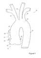
- FIG. 1shows an example of a patient's aorta
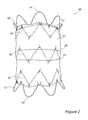
- FIG. 2is a side elevational view of a preferred embodiment of stent graft
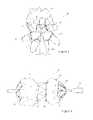
- FIG. 3is a view from the front of the stent graft of FIG. 2 showing the diameter constraining mechanism
- FIG. 4is a side elevational view of the stent graft of FIG. 2 in a partially constrained configuration
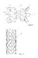
- FIG. 5is a side elevational view of the stent graft of FIG. 2 in a partially constrained configuration and with its distal end and the proximal bare stent released;
- FIG. 6is a side elevational view of an embodiment of stent for use in fixing the stent graft of FIG. 2 in position;
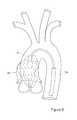
- FIG. 7is a schematic diagram of the stent graft of FIG. 2 and the stent of FIG. 6 in situ in the aorta of a patient;
- FIG. 8is a schematic diagram of the stent graft of FIG. 2 in a partly deployed configuration in the aorta of a patient;
- FIGS. 9 and 10are exploded views of an embodiment of introducer assembly for the stent graft of FIG. 2 ;
- FIG. 11is an enlarged view of the distal end of the introducer assembly of FIGS. 9 and 10 .
- the aortaincludes a descending aorta portion 12 leading to the aortic arch 14 from which extend the brachiocephalic artery 16 , the left common cartoid artery 18 and the left subclavian artery 20 . Beyond the aortic arch 14 there is the ascending aorta 22 leading to the heart opening 24 , just before which the coronary arteries 26 , 28 branch off.
- the length of lumen of the ascending aorta 22 free of branch arteriesis no more than around 50 to 60 mm, meaning that any medical device to be located in this area must be positioned very accurately in order not to run the risk of blocking any of the branching arteries or causing trauma to the tissue of the lumen walls.
- FIG. 2there is shown an embodiment of a stent graft 40 designed to be fitted into the ascending aorta 22 to treat a Type-A dissection 30 , 32 .
- the stent graft and introducer assembly disclosed hereinfocus upon the treatment of Type-A dissections, they can also be used to treat aortic ruptures, transactions, coronary dissections, valve ruptures, cardiac tamponades, distal malperfusions, aneurysms and other similar defects.
- the stent graft 40includes a tube 42 of graft material, which may be any of the currently available graft materials or other materials contemplated in the art.
- the graft tube 42preferably has a length of around 50-70 mm, in the preferred embodiment around 65 mm, and a diameter in the range from 28 mm to 46 mm. These dimensions do, of course, depend upon the size of a patient's ascending aorta 22 and the distance between the coronary arteries 26 , 28 and the brachiocephalic artery 16 .
- the stent graft 40is provided with five stent rings 44 , 46 , 48 , 50 and 52 , two of which, that is stents 44 and 52 , are bare stents which extend beyond the extremities of the graft tube 42 .
- the other three stent rings 46 - 50are, in this embodiment, disposed on the inside of the graft tube 42 and are spaced along its length, such that the rings 46 and 50 are proximate the ends of the graft tube while the stent ring 48 is approximately at its centre.
- the bare stents 44 and 52have, in the preferred embodiment, rounded apices 54 to minimize the risk of damage to the vessel walls. Although the preferred embodiment has two bare stents, a proximal stent 44 and a distal stent 52 , the distal stent 52 may be omitted. It will be seen from the drawings that at least the proximal bare stent 44 flares outwardly, that is radially beyond the graft tube 42 . The distal bare stent 52 may flare in similar manner.
- the internal stent rings 46 , 48 , 50may be conventional zigzag stent rings with pointed apices, although could have rounded apices as the bare stents 44 and 52 , or any other suitable stent ring design.
- the stent rings 44 , 46 , 48 , 50 , 52are sutured to the graft tube in conventional manner although they could be secured to the graft tube 42 by any other suitable means.
- the proximal suture loop 56extends around the proximal end of the graft tube 42 and in this embodiment feeds into and out of the graft material to provide a plurality of portions of thread substantially evenly radially spaced on the inside of the graft tube, for tying to the carrier of an introducer, as described in further detail below.
- the diameter reducing loop 56is usefully threaded into the inside of the graft tube at the apices of the stent 44 , such that the stent structure provides support for the loop 56 .
- the intermediate diameter reducing loops 58 , 60are, in this embodiment, provided at either end of the middle stent ring 48 and again feed into the inside of the graft tube 42 at the apices of the stent ring 48 .
- the distal end of the stent graft 40is not provided with any diameter reducing loops. In other embodiments, a further diameter reducing loop may be provided at this end of the graft tube 42 .
- FIG. 3there is shown the stent graft 40 constrained on an introducer (the latter being described in further detail below), with the diameter reducing loops 56 , 58 , 60 pulled by their portions which extend into the graft tubing 42 towards the centre-point of the stent graft (in practice towards the carrier cannula as shown in the Figure).
- the number of constraining points on the graft tube 42will depend upon the number of portions of loop 56 , 58 , 60 extending into the graft tube. In this example, there are three constraining points 56 ′, 58 ′, 60 ′ per loop, as will be apparent from FIG. 3 .
- FIG. 4there is shown a side elevational view of the stent graft 40 fitted onto the distal end of an introducer 100 and in a condition in which the stent graft 40 has been partially deployed but remains constrained on the introducer 100 .
- the diameter reducing loops 58 , 60constrain the radial expansion of the stent graft 40 until these are released from the introducer 100 , as described below.
- the stent graft 42produces two bulbous regions 62 , 64 either side of its centre portion and within the ends of the graft tube.
- the stent graft 40which could be described as being in a partially deployed configuration, can be repositioned in a patient's lumen thus to enable very accurate positioning of the stent graft in the ascending aorta 22 .
- FIG. 4also shows the ends of the bare stents 44 , 52 constrained to the carrier of the introducer.
- the stent graft 40is shown in a configuration in which the bare stents have been released from the carrier and thus are able to expand radially outwardly, in practice towards the lumen walls of a patient.
- both bare stents 44 , 52have been released, although in some embodiments the distal bare stent 52 may remain constrained until the remainder of the stent graft 40 has been deployed, that is being the last element of the stent graft which is released to expand. This is described in further detail below.
- distal stent 70for use with the stent graft 40 .
- the stent 70can take any desired form although in this embodiment is formed of a plurality of zigzag stent rings 72 tied together by a plurality of threads 74 .
- This type of stentis longitudinally very flexible yet can provide a good radial expansion force against the lumen walls.
- FIG. 7shows the stent graft 40 and stent 70 assembly fitted to a patient's aorta, specifically with the stent graft 40 located in the ascending aorta 22 and the stent 70 extending over the arterial branches 16 , 18 , 20 .
- the proximal bare stent 44locates into the bulbous region 23 of the aorta just by the heart opening 24 and across the coronary arteries 26 , 28 . Given its flaring configuration, the bare stent opens out into the bulbous region 23 and acts to assist in holding the stent graft 40 in position.
- the graft section 42extends over the entry point or tear 80 forming the opening of the dissection, and down close to the brachiocephalic artery 16 .
- the distal stent 70is positioned such that its proximal end fits inside and against the stent graft 40 and extends across the branch arteries 16 , 18 , 20 .
- the stent 70acts to press the distal end of the stent graft 40 against the lumen walls and to maintain the position of the stent graft 40 , thereby to prevent its migration.
- the stent graft 40 and stent 70could be formed integrally, that is as a unitary structure. It is preferred, however, that the two are separate components.
- FIG. 8shows the stent graft 40 in position in the ascending aorta in a partially deployed state and still attached to, and partially constrained to, the introducer 100 .
- the stent graft 40is able to expand towards the walls of the lumen but is still able to be moved backward and forward as necessary along the lumen to ensure its correct positioning before it is completely released from the introducer.
- FIGS. 2 to 8focus on an embodiment of stent graft provided with a plurality of diameter constricting devices 56 , 58 , 60 , these are not necessary in all embodiments of the invention.
- the stent graftcould be provided as a structure with a bare stent 44 at its proximal end and a plurality of stents coupled to the graft tube 42 .
- the loops 56 , 58 , 60 and the distal bare stent 52need not be used.
- the bare stent 44flares outwardly, in use to engage the concavity of the aortic sinus 23 and thus to act as an anchoring element to ensure that the stent graft 40 remains in place beyond the coronary arteries 26 , 28 and does not migrate to obstruct the brachiocephalic artery 16 .
- the bare stent 44preferably extends out of the graft tube by a predetermined distance to provide adequate anchoring to the aortic sinus 23 and may, for instance, extend by around 10 mm for an adult.
- This design of bare stentalso acts to resist any forces acting to push the device proximally as the bare stents will engage the aortic root tissue (the apices of the stent will be driven into the concave aortic root and will prevent proximal device motion).
- the stent graft 40also preferably includes the distal bare stent 52 , which has the function of anchoring the stent graft 40 against upstream migration, thereby preventing migration to the aortic valves.
- the bare stents 44 , 52thus enable the stent graft not to have any barbs, which can cause damage to the vessel walls.
- the amount of bare stent which is exposed beyond the graft tube 42can be controlled by the position of the sutures holding the bare stent.
- the embodiment of stent graft shownhas the stents 46 , 48 and 50 located inside the graft tube 42
- the middle stent 48is located on the outside of the graft tube 42 .
- the stent 48acts as a body stent providing longitudinal and circumferential stability to the device ensuring that the device confirms to the vasculature and does not buckle when deployed in angulated and/or tortuous anatomies.
- the stent 46 and 50are sealing stents which ensure good sealing of the stent graft 40 to the vessel walls.
- This embodiment of stent graftmay also be used with a distal stent of the type shown in FIG. 6 , which may be a separate component or integral with the stent graft 40 .
- the graft tubeas with the embodiment of FIGS. 2 to 8 , can have a length of around 50 to 70 mm for an adult and preferably a length of around 65 mm. It can have similar diameters as the embodiment of FIGS. 2 to 8 .
- the stentsare preferably formed from shape memory material, preferably Nitinol.
- the introducer 100includes an external manipulation section 112 , a distal attachment region 114 and a proximal attachment region 116 .
- the distal attachment region 114 and the proximal attachment region 116secure the distal and proximal ends of the stent graft 118 , respectively.
- the distal and proximal attachment regions 114 and 116will travel through the patient's lumen to a desired deployment site.
- the external manipulation section 112which is acted upon by a surgeon to manipulate the introducer, remains outside of the patient throughout the procedure.
- the proximal attachment region 116 of the introducer 110includes a dilator tip 120 , which is typically provided with a bore 122 therein for receiving a guide wire (not shown) of conventional type.
- the longitudinal bore 122also provides a channel for the introduction of medical reagents. For example, it may be desirable to supply a contrast agent to allow angiography to be performed during placement and deployment phases of the medical procedure.
- a guide wire catheter 124is fastened to the dilator tip 120 .
- the guide wire catheter 124is flexible so that the introducer 100 can be advanced along a relatively tortuous vessel, such as a femoral artery, and so that the distal attachment region 114 can be longitudinally and rotationally manipulated.
- the guide wire catheter 124extends through the introducer 100 to the manipulation section 112 , terminating at a connection device 126 , in conventional manner.
- connection device 126is designed to accept a syringe to facilitate the introduction of reagents into the inner catheter 124 .
- the guide wire catheter 124is in fluid communication with apertures 128 in the flexible dilator tip 120 . Therefore, reagents introduced into connection device 126 will flow to and emanate from the apertures 128 .
- a pusher sheath or rod 130(hereinafter referred to as a pusher member), typically made from a plastics material, is mounted coaxial with and radially outside of the guide wire catheter 124 .
- the pusher member 130is “thick walled”, that is the thickness of its wall is preferably several times greater than that of the guide wire catheter 124 .
- a sheath 132extends coaxially over and radially outside of the pusher member 130 .
- the pusher member 130 and the sheath 132extend distally to the manipulation region 112 .
- the implant 118which in this embodiment is the stent graft 40 , is retained in a compressed condition by the sheath 132 .
- the sheath 132extends distally to a sheath manipulator and haemostatic sealing unit 134 of the external manipulation section 112 .
- the haemostatic sealing unit 134includes a haemostatic seal (not shown) and a side tube 136 held to the unit 134 by a conventional luer lock 138 .
- the sheath manipulator and haemostatic sealing unit 134also includes a clamping collar (not shown) that clamps the sheath 132 to the haemostatic seal and a silicone seal ring (not shown) that forms a haemostatic seal around the pusher rod 130 .
- the side tube 138facilitates the introduction of medical fluids between the pusher rod 130 and the sheath 132 . Saline solution is typically used.
- the sheath 132is advanced over the proximal end of the dilator tip 120 of the proximal attachment region 116 while the implant 118 is held in a compressed state by an external force.
- a suitable distal attachment (retention) section(not visible in this view) is coupled to the pusher rod 130 and retains a distal end 140 of the prosthesis 118 during the procedure.
- the distal end of the prosthesis 118is provided with a plurality of trigger wires 142 , 144 .
- a proximal portion of the external manipulation section 112includes at least one release wire actuation section 150 mounted on a body 148 , in turn mounted onto the pusher member 130 .
- the guide wire catheter 124passes through the body 148 .
- the trigger wire release mechanisms 146 , 150are mounted for slidable movement on the body 148 .
- a haemostatic seal(not shown) is included so that the release wires can extend out through the body 148 without unnecessary blood loss during the medical procedure.
- a proximal portion of the external manipulation section 112includes a pin vise 154 mounted onto the proximal end of the body 148 .
- the pin vise 154has a screw cap 156 .
- vise jaws (not shown) of the pin vise 154clamp against or engage the guide wire catheter 124 .
- the guide wire catheter 124can only move with the body 148 and hence it can only move with the pusher member 130 .
- With the screw cap 156 tightenedthe entire assembly can be moved together as one piece.
- the cannula 124 which carries the stent graft 40is provided, in this embodiment, with first and second slots 160 , 162 in its wall.
- the slotsare sized to allow access to the trigger wires 142 , 144 and in particular to allow coupling of the diameter reducing suture loops 58 , 60 to the trigger wires.
- the trigger wires 142 , 144are arranged to be operated together.
- the trigger wires 142 , 144pass through the bore in the carrier 130 and by apertures at positions representative of the ends of the bare stents 44 , 52 as well as at the diameter reducing suture loops 56 , 58 , 60 .
- the trigger wirescan tie down, that is constrain radially, the stent graft 40 into the configuration shown in FIGS. 4 and 8 .
- the stent graft 40would be in a more longitudinally stretched condition than that shown in FIGS. 4 and 8 , such that it would bulge outwardly less than shown in these drawings.
- the outer sheath 132covers the stent graft for the deployment procedure, thus pressing the entirety of the stent graft 40 against the carrier 124 .
- the sheath 132is pulled back, that is withdrawn, to expose the stent graft 40 .
- the stent graft 40is able to deploy to its partly expanded position, shown in FIGS. 4 and 8 . In this configuration, it is still possible to adjust the position of the stent graft 40 within the ascending aorta 22 to ensure its precise positioning. Once the surgeon is satisfied with this positioning, the trigger wires can be released.
- the stent graft 40is released from its proximal position first. That is, the proximal bare stent 44 is first released, whereupon it can flare outwardly. As the trigger wires continue to be withdrawn, the first diameter constraining loop 56 is then released, allowing the proximal end of the graft tube 42 to expand. In this configuration, it is still possible to adjust the position of the stent graft 40 and in particular to ensure that its proximal end avoids blocking the coronary arteries 26 , 28 and that the bare stent 44 is made to sit at the aperture of the bulbous part 23 of the aorta.
- the stent graft 40will abut against the false lumen walls and thus be partially held in place by these, until full deployment thereof.
- the trigger wiresare withdrawn further, releasing in sequence, the diameter reducing loops 58 and 60 and then the distal bare stent 52 .
- the stent graft 40is deployed in stages and in a manner that its position can be precisely adjusted.
- the distal stent 70is deployed in a second phase of the deployment operation, by expanding this such that its proximal end fits within the distal end of the stent graft 40 , as shown for instance in FIG. 7 .
- the deployment sequencecan be altered, particularly by providing additional trigger mechanisms.
- the distal bare stent 52could be retained by a sleeve rather than the trigger wires, and thus deployable independently of the trigger wires.
- the body of the stent graft 40before releasing the end of the stent graft, that is the bare stents 44 , 52 .
Landscapes
- Health & Medical Sciences (AREA)
- Engineering & Computer Science (AREA)
- Biomedical Technology (AREA)
- Heart & Thoracic Surgery (AREA)
- Oral & Maxillofacial Surgery (AREA)
- Transplantation (AREA)
- Cardiology (AREA)
- Vascular Medicine (AREA)
- Life Sciences & Earth Sciences (AREA)
- Animal Behavior & Ethology (AREA)
- General Health & Medical Sciences (AREA)
- Public Health (AREA)
- Veterinary Medicine (AREA)
- Pulmonology (AREA)
- Gastroenterology & Hepatology (AREA)
- Prostheses (AREA)
Abstract
Description
Claims (19)
Applications Claiming Priority (2)
| Application Number | Priority Date | Filing Date | Title |
|---|---|---|---|
| GB0920327AGB2476451A (en) | 2009-11-19 | 2009-11-19 | Stent Graft |
| GB0920327.4 | 2009-11-19 |
Publications (2)
| Publication Number | Publication Date |
|---|---|
| US20110125249A1 US20110125249A1 (en) | 2011-05-26 |
| US9717611B2true US9717611B2 (en) | 2017-08-01 |
Family
ID=41565589
Family Applications (1)
| Application Number | Title | Priority Date | Filing Date |
|---|---|---|---|
| US12/946,238Active2031-01-22US9717611B2 (en) | 2009-11-19 | 2010-11-15 | Stent graft and introducer assembly |
Country Status (2)
| Country | Link |
|---|---|
| US (1) | US9717611B2 (en) |
| GB (1) | GB2476451A (en) |
Cited By (2)
| Publication number | Priority date | Publication date | Assignee | Title |
|---|---|---|---|---|
| US10888414B2 (en) | 2019-03-20 | 2021-01-12 | inQB8 Medical Technologies, LLC | Aortic dissection implant |
| US11660179B2 (en) | 2018-05-31 | 2023-05-30 | Endologix Llc | Stent graft systems with restraints in channels and methods thereof |
Families Citing this family (10)
| Publication number | Priority date | Publication date | Assignee | Title |
|---|---|---|---|---|
| US10098767B2 (en) | 2012-04-27 | 2018-10-16 | Medtronic Vascular, Inc. | Reconfigurable stent-graft delivery system and method of use |
| US9737394B2 (en) | 2012-04-27 | 2017-08-22 | Medtronic Vascular, Inc. | Stent-graft prosthesis for placement in the abdominal aorta |
| US8968384B2 (en) | 2012-04-27 | 2015-03-03 | Medtronic Vascular, Inc. | Circumferentially constraining sutures for a stent-graft |
| US9452069B2 (en) | 2012-04-27 | 2016-09-27 | Medtronic Vascular, Inc. | Reconfigurable stent-graft delivery system and method of use |
| US9393140B2 (en) | 2012-04-27 | 2016-07-19 | Medtronic Vascular, Inc. | Reconfigurable stent-graft delivery system and method of use |
| EP2749310A1 (en)* | 2012-12-28 | 2014-07-02 | Cook Medical Technologies LLC | Ureteral endoluminal device |
| US10610393B2 (en) | 2016-03-24 | 2020-04-07 | Cook Medical Technologies Llc | Wire retention and release mechanisms |
| DE202016105963U1 (en) | 2016-10-24 | 2018-01-25 | Nvt Ag | Intraluminal vascular prosthesis for implantation in the heart or cardiac vessels of a patient |
| US11678970B2 (en) | 2018-12-04 | 2023-06-20 | Boston Scientific Scimed, Inc. | Device for anastomotic bypass |
| JP7411800B2 (en) | 2019-11-18 | 2024-01-11 | ボストン サイエンティフィック サイムド,インコーポレイテッド | Stents with improved anti-migration properties |
Citations (179)
| Publication number | Priority date | Publication date | Assignee | Title |
|---|---|---|---|---|
| US5258021A (en) | 1992-01-27 | 1993-11-02 | Duran Carlos G | Sigmoid valve annuloplasty ring |
| US5292331A (en) | 1989-08-24 | 1994-03-08 | Applied Vascular Engineering, Inc. | Endovascular support device |
| US5403341A (en) | 1994-01-24 | 1995-04-04 | Solar; Ronald J. | Parallel flow endovascular stent and deployment apparatus therefore |
| EP0686379A2 (en) | 1994-06-08 | 1995-12-13 | Cardiovascular Concepts, Inc. | Apparatus for endoluminal graft placement |
| US5569295A (en) | 1993-12-28 | 1996-10-29 | Advanced Cardiovascular Systems, Inc. | Expandable stents and method for making same |
| US5607468A (en) | 1994-11-04 | 1997-03-04 | Aeroquip Corporation | Method of manufacturing an intraluminal stenting graft |
| US5630829A (en) | 1994-12-09 | 1997-05-20 | Intervascular, Inc. | High hoop strength intraluminal stent |
| WO1997021403A1 (en) | 1995-12-14 | 1997-06-19 | Prograft Medical, Inc. | Kink-resistant stent graft |
| US5674278A (en) | 1989-08-24 | 1997-10-07 | Arterial Vascular Engineering, Inc. | Endovascular support device |
| US5749921A (en) | 1996-02-20 | 1998-05-12 | Medtronic, Inc. | Apparatus and methods for compression of endoluminal prostheses |
| US5782904A (en) | 1993-09-30 | 1998-07-21 | Endogad Research Pty Limited | Intraluminal graft |
| US5843164A (en) | 1994-11-15 | 1998-12-01 | Advanced Carrdiovascular Systems, Inc. | Intraluminal stent for attaching a graft |
| US5855601A (en) | 1996-06-21 | 1999-01-05 | The Trustees Of Columbia University In The City Of New York | Artificial heart valve and method and device for implanting the same |
| US5906639A (en) | 1994-08-12 | 1999-05-25 | Meadox Medicals, Inc. | High strength and high density intraluminal wire stent |
| US5913897A (en) | 1993-09-16 | 1999-06-22 | Cordis Corporation | Endoprosthesis having multiple bridging junctions and procedure |
| US5961546A (en) | 1993-04-22 | 1999-10-05 | C.R. Bard, Inc. | Method and apparatus for recapture of hooked endoprosthesis |
| US5993482A (en) | 1996-01-04 | 1999-11-30 | Endovascular Technologies, Inc. | Flat wire stent |
| EP0960607A1 (en) | 1998-05-28 | 1999-12-01 | Medtronic Ave, Inc. | Endoluminal support assembly with capped ends |
| US6071307A (en) | 1998-09-30 | 2000-06-06 | Baxter International Inc. | Endoluminal grafts having continuously curvilinear wireforms |
| US6110198A (en) | 1995-10-03 | 2000-08-29 | Medtronic Inc. | Method for deploying cuff prostheses |
| US6203569B1 (en) | 1996-01-04 | 2001-03-20 | Bandula Wijay | Flexible stent |
| US20010000188A1 (en)* | 1996-01-05 | 2001-04-05 | Lenker Jay A. | Limited expansion endoluminal prostheses and methods for their use |
| US6245102B1 (en) | 1997-05-07 | 2001-06-12 | Iowa-India Investments Company Ltd. | Stent, stent graft and stent valve |
| US6287315B1 (en) | 1995-10-30 | 2001-09-11 | World Medical Manufacturing Corporation | Apparatus for delivering an endoluminal prosthesis |
| US6293966B1 (en) | 1997-05-06 | 2001-09-25 | Cook Incorporated | Surgical stent featuring radiopaque markers |
| US6296662B1 (en) | 1999-05-26 | 2001-10-02 | Sulzer Carbiomedics Inc. | Bioprosthetic heart valve with balanced stent post deflection |
| US6336937B1 (en) | 1998-12-09 | 2002-01-08 | Gore Enterprise Holdings, Inc. | Multi-stage expandable stent-graft |
| US20020016627A1 (en) | 2000-01-19 | 2002-02-07 | Scimed Life Systems, Inc. | Tubular structure/stent/stent securement member |
| US6346118B1 (en) | 1983-12-09 | 2002-02-12 | Endovascular Technologies, Inc. | Thoracic graft and delivery catheter |
| US6348068B1 (en) | 1999-07-23 | 2002-02-19 | Sulzer Carbomedics Inc. | Multi-filament valve stent for a cardisc valvular prosthesis |
| US20020022877A1 (en) | 2000-03-15 | 2002-02-21 | Biotronik Mess-Und Therapiegeraete Gmbh & Co. | Stent |
| US6350277B1 (en) | 1999-01-15 | 2002-02-26 | Scimed Life Systems, Inc. | Stents with temporary retaining bands |
| US20020032487A1 (en) | 1998-08-31 | 2002-03-14 | Wilson-Cook Medical Incorporated | Prosthesis having a sleeve valve |
| US6368345B1 (en) | 1998-09-30 | 2002-04-09 | Edwards Lifesciences Corporation | Methods and apparatus for intraluminal placement of a bifurcated intraluminal garafat |
| US6423090B1 (en) | 2000-02-11 | 2002-07-23 | Advanced Cardiovascular Systems, Inc. | Stent pattern with staged expansion |
| US6451051B2 (en) | 1999-04-26 | 2002-09-17 | William J. Drasler | Intravascular folded tubular endoprosthesis |
| WO2002076340A2 (en) | 2001-03-27 | 2002-10-03 | Scimed Life Systems, Inc. | Stent with controlled expansion |
| WO2002078569A2 (en) | 2001-03-28 | 2002-10-10 | Cook Incorporated | Modular stent graft assembly and use thereof |
| US6471722B1 (en) | 1995-05-19 | 2002-10-29 | Kanji Inoue | Appliance to be implanted and a device for handling the appliance to be implanted |
| US20020177890A1 (en) | 1996-01-05 | 2002-11-28 | Lenker Jay A. | Stent graft loading and deployment device and method |
| US6514282B1 (en) | 1999-10-04 | 2003-02-04 | Kanji Inoue | Method of folding transplanting instrument and transplanting instrument |
| US20030033002A1 (en) | 1998-09-30 | 2003-02-13 | Edwards Lifesciences, Llc | Aorto uni-iliac graft |
| US20030033003A1 (en) | 2001-08-13 | 2003-02-13 | Harrison William James | Apparatus and method for decreasing stent gap size |
| US6524335B1 (en) | 1997-12-10 | 2003-02-25 | William A. Cook Australia Pty. Ltd. | Endoluminal aortic stents |
| US20030050684A1 (en) | 2001-09-10 | 2003-03-13 | Abrams Robert M. | Internal restraint for delivery of self-expanding stents |
| US6539984B2 (en) | 2000-07-12 | 2003-04-01 | Edwards Lifesciences Corporation | Method and apparatus for forming a heart valve wireform |
| US6551350B1 (en) | 1996-12-23 | 2003-04-22 | Gore Enterprise Holdings, Inc. | Kink resistant bifurcated prosthesis |
| WO2003034948A1 (en) | 2001-10-26 | 2003-05-01 | Cook Incorporated | Prostheses for curved lumens |
| US6579314B1 (en) | 1995-03-10 | 2003-06-17 | C.R. Bard, Inc. | Covered stent with encapsulated ends |
| US20030120263A1 (en) | 2001-12-20 | 2003-06-26 | The Cleveland Clinic Foundation | Apparatus and method for capturing a wire in a blood vessel |
| US20030120331A1 (en) | 2001-12-20 | 2003-06-26 | Trivascular, Inc. | Advanced endovascular graft |
| US6585757B1 (en) | 1999-09-15 | 2003-07-01 | Advanced Cardiovascular Systems, Inc. | Endovascular stent with radiopaque spine |
| US20030125797A1 (en) | 2001-12-20 | 2003-07-03 | Trivascular, Inc. | Advanced endovascular graft |
| US20030130720A1 (en) | 2002-01-08 | 2003-07-10 | Depalma Donald F. | Modular aneurysm repair system |
| US6616689B1 (en) | 2000-05-03 | 2003-09-09 | Advanced Cardiovascular Systems, Inc. | Intravascular stent |
| US6629994B2 (en) | 2001-06-11 | 2003-10-07 | Advanced Cardiovascular Systems, Inc. | Intravascular stent |
| WO2003082153A2 (en) | 2002-03-25 | 2003-10-09 | Cook Incorporated | Branched vessel prothesis |
| US6635083B1 (en) | 2001-06-25 | 2003-10-21 | Advanced Cardiovascular Systems, Inc. | Stent with non-linear links and method of use |
| US6645242B1 (en) | 2000-12-11 | 2003-11-11 | Stephen F. Quinn | Bifurcated side-access intravascular stent graft |
| US6648911B1 (en) | 2000-11-20 | 2003-11-18 | Avantec Vascular Corporation | Method and device for the treatment of vulnerable tissue site |
| US6663661B2 (en) | 1989-08-24 | 2003-12-16 | Medtronic Ave, Inc. | Endovascular support device and method |
| US6673102B1 (en) | 1999-01-22 | 2004-01-06 | Gore Enterprises Holdings, Inc. | Covered endoprosthesis and delivery system |
| US6695875B2 (en)* | 2000-03-14 | 2004-02-24 | Cook Incorporated | Endovascular stent graft |
| WO2004017867A1 (en) | 2002-08-23 | 2004-03-04 | William A. Cook Australia Pty. Ltd. | Composite prosthesis |
| WO2004017868A1 (en) | 2002-08-23 | 2004-03-04 | William A. Cook Australia Pty. Ltd. | Asymmetric stent graft attachment |
| US20040054396A1 (en) | 2002-06-26 | 2004-03-18 | Cook Incorporated | Stent-graft fastening |
| US6723116B2 (en)* | 2002-01-14 | 2004-04-20 | Syde A. Taheri | Exclusion of ascending/descending aorta and/or aortic arch aneurysm |
| US20040093063A1 (en) | 2002-06-07 | 2004-05-13 | Wright Michael T. | Controlled deployment delivery system |
| US20040106978A1 (en) | 2002-06-28 | 2004-06-03 | Cook Incorporated | Thoracic aortic aneurysm stent graft |
| US20040117003A1 (en) | 2002-05-28 | 2004-06-17 | The Cleveland Clinic Foundation | Minimally invasive treatment system for aortic aneurysms |
| US20040117004A1 (en) | 2002-05-16 | 2004-06-17 | Osborne Thomas A. | Stent and method of forming a stent with integral barbs |
| US20040176833A1 (en) | 2002-11-22 | 2004-09-09 | Cook Incorporated | Stent tissue graft prosthesis |
| US20040215319A1 (en) | 2003-04-24 | 2004-10-28 | Humberto Berra | Stent graft tapered spring |
| US20040215316A1 (en) | 2000-10-06 | 2004-10-28 | The Board Of Regents Of The University Of Texas System | Percutaneous implantation of partially covered stents in aneurysmally dilated arterial segments with subsequent embolization and obliteration of the aneurysm cavity |
| US20040254625A1 (en) | 2003-06-13 | 2004-12-16 | Trivascular, Inc. | Inflatable implant |
| US20050033406A1 (en) | 2003-07-15 | 2005-02-10 | Barnhart William H. | Branch vessel stent and graft |
| US6860901B1 (en) | 1988-03-09 | 2005-03-01 | Endovascular Technologies, Inc. | Intraluminal grafting system |
| US20050049674A1 (en) | 2003-09-03 | 2005-03-03 | Berra Humberto A. | Stent graft |
| US20050075730A1 (en) | 2003-10-06 | 2005-04-07 | Myers Keith E. | Minimally invasive valve replacement system |
| WO2005034810A1 (en) | 2003-10-10 | 2005-04-21 | Cook Incorporated | Stretchable prosthesis fenestration |
| US20050090834A1 (en) | 2003-10-23 | 2005-04-28 | Aptus Endosystems, Inc. | Prosthesis delivery systems and methods |
| US20050102022A1 (en) | 2002-08-15 | 2005-05-12 | Gmp Cardiac Care, Inc. | Stent-graft with rails |
| US20050113905A1 (en) | 2003-10-10 | 2005-05-26 | Greenberg Roy K. | Endoluminal prosthesis with interconnectable modules |
| US20050119722A1 (en) | 2003-09-12 | 2005-06-02 | Mikolaj Styrc | Device for treating a blood vessel and a method of preparing the device |
| US20050131516A1 (en) | 2003-09-29 | 2005-06-16 | Secant Medical, Llc | Integral support stent graft assembly |
| US20050154446A1 (en) | 1998-01-26 | 2005-07-14 | Peter Phillips | Reinforced graft |
| US20050159803A1 (en) | 2004-01-20 | 2005-07-21 | Cook Incorporated | Endoluminal prosthetic device |
| US20050222669A1 (en) | 2004-03-31 | 2005-10-06 | Purdy James D | Fenestrated intraluminal stent system |
| US20050222671A1 (en) | 2004-03-31 | 2005-10-06 | Schaeffer Darin G | Partially biodegradable stent |
| WO2005099628A2 (en) | 2004-04-13 | 2005-10-27 | Cook Incorporated | Implantable frame with variable compliance |
| US20050240257A1 (en) | 2002-05-20 | 2005-10-27 | Kawasumi Laboratories, Inc. | Stent and stent graft |
| US20050240258A1 (en) | 2001-11-28 | 2005-10-27 | Aptus Endosystems, Inc. | Multi-lumen prosthesis systems and methods |
| US6962604B2 (en) | 1999-10-05 | 2005-11-08 | Scimed Life Systems, Inc. | Flexible endoluminal stent and process of repairing a body lumen |
| US20050273155A1 (en) | 2002-08-20 | 2005-12-08 | Bahler Clinton D | Endoluminal device with extracellular matrix material and methods |
| US20060004436A1 (en) | 2004-07-02 | 2006-01-05 | Amarant Paul D | Stent having arcuate struts |
| US20060004433A1 (en)* | 2004-06-16 | 2006-01-05 | Cook Incorporated | Thoracic deployment device and stent graft |
| US20060052860A1 (en) | 2001-06-11 | 2006-03-09 | Gomez Andreina P | Intravascular stent |
| WO2006028925A1 (en) | 2004-09-02 | 2006-03-16 | Med Institute, Inc. | Modular prosthesis and method for branch vessels |
| US20060100695A1 (en) | 2002-09-27 | 2006-05-11 | Peacock James C Iii | Implantable stent with modified ends |
| US20060161243A1 (en) | 2004-12-09 | 2006-07-20 | Cook Group Patent Office | S-shaped stent design |
| US20060184228A1 (en) | 2005-02-17 | 2006-08-17 | Khoury Michael D | Vascular endograft |
| US20060190075A1 (en) | 2005-01-28 | 2006-08-24 | Boston Scientific Scimed, Inc. | Stent retrieval member and devices and methods for retrieving or repositioning a stent |
| US20060190070A1 (en) | 2005-02-23 | 2006-08-24 | Dieck Martin S | Rail stent and methods of use |
| US20060247761A1 (en) | 2003-01-14 | 2006-11-02 | The Cleveland Clinic Foundation | Branched vessel endoluminal device with fenestration |
| US20060265054A1 (en) | 2003-05-29 | 2006-11-23 | Greenhalgh Skott E | Filament Based Prosthesis |
| US20060267247A1 (en) | 2002-07-02 | 2006-11-30 | Boris Anukhin | Nitinol frame heating and setting mandrel |
| US20070027525A1 (en) | 2003-11-19 | 2007-02-01 | Neovasc Medical Ltd | Vascular implant |
| US20070043425A1 (en) | 2005-08-18 | 2007-02-22 | William A. Cook Australia Pty Ltd. | Assembly of stent grafts |
| US7186263B2 (en) | 1999-05-20 | 2007-03-06 | Scimed Life Systems, Inc. | Mesh graft and stent for increased flexibility |
| US20070055347A1 (en) | 2005-09-02 | 2007-03-08 | Medtronic Vascular, Inc., A Delaware Corporation | Endoluminal prosthesis |
| US20070067016A1 (en) | 2003-09-16 | 2007-03-22 | Johannes Jung | Stent comprising terminal anchoring elements |
| US20070073388A1 (en) | 2005-08-22 | 2007-03-29 | Krolik Jeffrey A | Flared stents and apparatus and methods for delivering them |
| US20070100427A1 (en) | 2005-11-02 | 2007-05-03 | Eric Perouse | Device for treating a blood vessel and associated treatment kit |
| US20070135889A1 (en) | 2003-09-03 | 2007-06-14 | Bolton Medical, Inc. | Lumen repair device with capture structure |
| US20070150051A1 (en) | 2005-01-10 | 2007-06-28 | Duke Fiduciary, Llc | Vascular implants and methods of fabricating the same |
| US20070162103A1 (en)* | 2001-02-05 | 2007-07-12 | Cook Incorporated | Implantable device with remodelable material and covering material |
| US20070168019A1 (en) | 2006-01-13 | 2007-07-19 | Aga Medical Corporation | Intravascular deliverable stent for reinforcement of vascular abnormalities |
| US20070179592A1 (en) | 2003-11-08 | 2007-08-02 | Schaeffer Darin G | Branch vessel prosthesis with positional indicator system and method |
| US20070185560A1 (en) | 2005-11-28 | 2007-08-09 | Cook Incorporated | Expandable stent |
| WO2007092276A2 (en) | 2006-02-03 | 2007-08-16 | Bolton Medical, Inc. | Delivery system and meth0d for self-centering a proximal end of a stent graft |
| US20070191927A1 (en) | 2005-11-07 | 2007-08-16 | Bowe Jason S | Stent with orientation-dependent properties |
| WO2007095283A2 (en) | 2006-02-13 | 2007-08-23 | Willam A. Cook Australia Pty. Ltd. | Side branch stent graft construction |
| US20070208256A1 (en) | 2006-03-03 | 2007-09-06 | Medtronic Vascular, Inc. | Multiple Branch Tubular Prosthesis and Methods |
| WO2007098937A1 (en) | 2006-02-28 | 2007-09-07 | Angiomed Gmbh & Co. Medizintechnik Kg | Flexible stretch stent-graft |
| US20070219620A1 (en) | 2004-04-12 | 2007-09-20 | Cook Incorporated | Stent Graft Repair Device |
| US20070219624A1 (en) | 2002-10-09 | 2007-09-20 | Boston Scientific Scimed, Inc. | Intraluminal medical device having improved visibility |
| US20070225797A1 (en) | 2006-03-24 | 2007-09-27 | Medtronic Vascular, Inc. | Prosthesis With Adjustable Opening for Side Branch Access |
| EP1839624A1 (en) | 2006-03-30 | 2007-10-03 | Medtronic Vascular, Inc. | Prosthesis with coupling zone methods |
| US20070233220A1 (en)* | 2006-03-30 | 2007-10-04 | Medtronic Vascular, Inc. | Prosthesis With Guide Lumen |
| US20070233223A1 (en) | 2006-04-04 | 2007-10-04 | Mikolaj Styrc | Device for treating a blood circulation canal and process for preparing this device |
| US20070244547A1 (en) | 2006-04-18 | 2007-10-18 | Medtronic Vascular, Inc., A Delaware Corporation | Device and Method for Controlling the Positioning of a Stent Graft Fenestration |
| US20070250152A1 (en) | 2006-04-21 | 2007-10-25 | Medtronic Vascular, Inc. A Delaware Corporation | Stent Graft Having Short Tube Graft for Branch Vessel |
| KR100772472B1 (en) | 2006-05-16 | 2007-11-06 | 주식회사 에스앤지바이오텍 | Artificial vessel stent insertion device |
| US20070282433A1 (en) | 2006-06-01 | 2007-12-06 | Limon Timothy A | Stent with retention protrusions formed during crimping |
| US7318835B2 (en) | 2004-07-20 | 2008-01-15 | Medtronic Vascular, Inc. | Endoluminal prosthesis having expandable graft sections |
| US20080033527A1 (en) | 2006-07-07 | 2008-02-07 | Anthony Nunez | Methods and systems for monitoring an endoprosthetic implant |
| US20080039920A1 (en) | 2006-08-08 | 2008-02-14 | Medlogics Device Corporation | Tethered Self-Expanding Stent Delivery System |
| US7331992B2 (en) | 2002-02-20 | 2008-02-19 | Bard Peripheral Vascular, Inc. | Anchoring device for an endoluminal prosthesis |
| WO2008021556A1 (en) | 2006-08-18 | 2008-02-21 | William A. Cook Australia Pty. Ltd. | Stent graft extension |
| US7341598B2 (en) | 1999-01-13 | 2008-03-11 | Boston Scientific Scimed, Inc. | Stent with protruding branch portion for bifurcated vessels |
| US20080086190A1 (en) | 2006-08-22 | 2008-04-10 | Diem Uyen Ta | Intravascular stent |
| WO2008051543A2 (en) | 2006-10-24 | 2008-05-02 | Cook Incorported | Stent member |
| US20080109066A1 (en) | 2000-12-11 | 2008-05-08 | Quinn Stephen F | Bifurcated side-access intravascular stent graft |
| US20080114441A1 (en) | 2006-11-14 | 2008-05-15 | Medtronic Vascular, Inc. | Endoluminal Prosthesis |
| US20080119943A1 (en) | 2006-11-16 | 2008-05-22 | Armstrong Joseph R | Stent having flexibly connected adjacent stent elements |
| WO2008066923A1 (en) | 2006-11-30 | 2008-06-05 | William Cook Europe Aps | Implant release mechanism |
| US20080195191A1 (en) | 2005-05-24 | 2008-08-14 | Qiyi Luo | Flexible Stent-Graft |
| US20080269866A1 (en) | 2007-04-24 | 2008-10-30 | Hamer Rochelle M | Side Branched Endoluminal Prostheses and Methods fo Delivery Thereof |
| US20080281399A1 (en) | 2004-06-15 | 2008-11-13 | Williams A. Cook Australia Pty. Ltd. | Stent Graft With Internal Tube |
| US20080319534A1 (en) | 2007-06-22 | 2008-12-25 | Medtronic Vascular, Inc. | Stent With Improved Mechanical Properties |
| US20090005856A1 (en) | 2007-06-27 | 2009-01-01 | Abbott Laboratories | Endoprostheses for peripheral arteries and other body vessels |
| US7473275B2 (en) | 2005-04-06 | 2009-01-06 | Edwards Lifesciences Corporation | Stress absorbing flexible heart valve frame |
| US20090043376A1 (en) | 2007-08-08 | 2009-02-12 | Hamer Rochelle M | Endoluminal Prosthetic Conduit Systems and Method of Coupling |
| WO2009020653A1 (en) | 2007-08-08 | 2009-02-12 | Cleveland Clinic Foundation | Branched stent graft system |
| US20090105809A1 (en) | 2007-10-19 | 2009-04-23 | Lee Michael J | Implantable and lumen-supporting stents and related methods of manufacture and use |
| US20090138072A1 (en) | 2001-11-28 | 2009-05-28 | Michael William Gendreau | Devices, systems, and methods for endovascular staple and/or prosthesis delivery and implantation |
| US20090149946A1 (en) | 2007-12-05 | 2009-06-11 | Cook Incorporated | Stent having at least one barb and methods of manufacture |
| US20090171437A1 (en) | 2007-12-26 | 2009-07-02 | Cook Incorporated | Low profile non-symmetrical stent |
| US20090177270A1 (en) | 2008-01-08 | 2009-07-09 | Cook Incorporated | Flow-Deflecting Prosthesis for Treating Venous Disease |
| US20090306763A1 (en) | 2007-12-26 | 2009-12-10 | Roeder Blayne A | Low profile non-symmetrical bare alignment stents with graft |
| WO2010024879A1 (en) | 2008-08-26 | 2010-03-04 | William A. Cook Australia Pty. Ltd. | Thoracic aorta stent graft with access region |
| WO2010062355A1 (en) | 2008-10-31 | 2010-06-03 | William Cook Europe Aps | Introducer for deploying a stent graft in a curved lumen and stent graft therefor |
| US7758626B2 (en) | 2004-07-20 | 2010-07-20 | Medtronic Vascular, Inc. | Device and method for delivering an endovascular stent-graft having a longitudinally unsupported portion |
| US7766962B1 (en) | 2003-03-21 | 2010-08-03 | Quinn Stephen F | Intravascular stent grafts and methods for deploying the same |
| US20100268318A1 (en)* | 2009-04-16 | 2010-10-21 | Medtronic Vascular, Inc. | Prosthesis for Antegrade Deployment |
| US20100331960A1 (en)* | 2009-06-30 | 2010-12-30 | Boston Scientific Scimed, Inc. | Endoprosthesis and endoprosthesis delivery system and method |
| US20120029624A1 (en) | 2009-03-16 | 2012-02-02 | Dierking W Kurt | Hybrid stent and method of making such a stent |
| US8128678B2 (en) | 2008-09-02 | 2012-03-06 | Cook Medical Technologies Llc | Stent having less invasive ends and improved radial force |
| US20120239136A1 (en) | 2009-05-08 | 2012-09-20 | National University Of Ireland, Galway | Flexible intraluminal stent |
| US8333799B2 (en) | 2007-02-12 | 2012-12-18 | C. R. Bard, Inc. | Highly flexible stent and method of manufacture |
| US20120323307A1 (en) | 1998-12-03 | 2012-12-20 | Medinol Ltd. | Hybrid stent |
| US8348994B2 (en) | 2007-03-09 | 2013-01-08 | Novostent Corporation | Vascular prosthesis with alternating helical sections |
| US8425586B2 (en) | 2009-09-02 | 2013-04-23 | Novostent Corporation | Vascular prosthesis with stress relief slots |
| US8480725B2 (en) | 2008-10-31 | 2013-07-09 | Cook Medical Technologies Llc | Introducer for deploying a stent graft in a curved lumen |
| US8728145B2 (en) | 2008-12-11 | 2014-05-20 | Cook Medical Technologies Llc | Low profile non-symmetrical stents and stent-grafts |
| US8992593B2 (en) | 2007-12-26 | 2015-03-31 | Cook Medical Technologies Llc | Apparatus and methods for deployment of a modular stent-graft system |
| US9220617B2 (en) | 2003-09-03 | 2015-12-29 | Bolton Medical, Inc. | Dual capture device for stent graft delivery system and method for capturing a stent graft |
| US9226814B2 (en) | 2009-11-18 | 2016-01-05 | Cook Medical Technologies Llc | Stent graft and introducer assembly |
| US9226813B2 (en) | 2007-12-26 | 2016-01-05 | Cook Medical Technologies Llc | Low profile non-symmetrical stent |
- 2009
- 2009-11-19GBGB0920327Apatent/GB2476451A/ennot_activeWithdrawn
- 2010
- 2010-11-15USUS12/946,238patent/US9717611B2/enactiveActive
Patent Citations (224)
| Publication number | Priority date | Publication date | Assignee | Title |
|---|---|---|---|---|
| US6346118B1 (en) | 1983-12-09 | 2002-02-12 | Endovascular Technologies, Inc. | Thoracic graft and delivery catheter |
| US6860901B1 (en) | 1988-03-09 | 2005-03-01 | Endovascular Technologies, Inc. | Intraluminal grafting system |
| US5292331A (en) | 1989-08-24 | 1994-03-08 | Applied Vascular Engineering, Inc. | Endovascular support device |
| US6663661B2 (en) | 1989-08-24 | 2003-12-16 | Medtronic Ave, Inc. | Endovascular support device and method |
| US5674278A (en) | 1989-08-24 | 1997-10-07 | Arterial Vascular Engineering, Inc. | Endovascular support device |
| US5258021A (en) | 1992-01-27 | 1993-11-02 | Duran Carlos G | Sigmoid valve annuloplasty ring |
| US5961546A (en) | 1993-04-22 | 1999-10-05 | C.R. Bard, Inc. | Method and apparatus for recapture of hooked endoprosthesis |
| US5913897A (en) | 1993-09-16 | 1999-06-22 | Cordis Corporation | Endoprosthesis having multiple bridging junctions and procedure |
| US5782904A (en) | 1993-09-30 | 1998-07-21 | Endogad Research Pty Limited | Intraluminal graft |
| US6582458B1 (en) | 1993-09-30 | 2003-06-24 | Geoffrey H. White | Intraluminal graft |
| US5569295A (en) | 1993-12-28 | 1996-10-29 | Advanced Cardiovascular Systems, Inc. | Expandable stents and method for making same |
| US5403341A (en) | 1994-01-24 | 1995-04-04 | Solar; Ronald J. | Parallel flow endovascular stent and deployment apparatus therefore |
| US8206427B1 (en)* | 1994-06-08 | 2012-06-26 | Medtonic Vascular, Inc. | Apparatus and methods for endoluminal graft placement |
| EP0686379A2 (en) | 1994-06-08 | 1995-12-13 | Cardiovascular Concepts, Inc. | Apparatus for endoluminal graft placement |
| US5906639A (en) | 1994-08-12 | 1999-05-25 | Meadox Medicals, Inc. | High strength and high density intraluminal wire stent |
| US5607468A (en) | 1994-11-04 | 1997-03-04 | Aeroquip Corporation | Method of manufacturing an intraluminal stenting graft |
| US5843164A (en) | 1994-11-15 | 1998-12-01 | Advanced Carrdiovascular Systems, Inc. | Intraluminal stent for attaching a graft |
| US5630829A (en) | 1994-12-09 | 1997-05-20 | Intervascular, Inc. | High hoop strength intraluminal stent |
| US6740115B2 (en)* | 1995-03-10 | 2004-05-25 | C. R. Bard, Inc. | Covered stent with encapsulated ends |
| US6579314B1 (en) | 1995-03-10 | 2003-06-17 | C.R. Bard, Inc. | Covered stent with encapsulated ends |
| US6471722B1 (en) | 1995-05-19 | 2002-10-29 | Kanji Inoue | Appliance to be implanted and a device for handling the appliance to be implanted |
| US6110198A (en) | 1995-10-03 | 2000-08-29 | Medtronic Inc. | Method for deploying cuff prostheses |
| US6287315B1 (en) | 1995-10-30 | 2001-09-11 | World Medical Manufacturing Corporation | Apparatus for delivering an endoluminal prosthesis |
| WO1997021403A1 (en) | 1995-12-14 | 1997-06-19 | Prograft Medical, Inc. | Kink-resistant stent graft |
| US5993482A (en) | 1996-01-04 | 1999-11-30 | Endovascular Technologies, Inc. | Flat wire stent |
| US6203569B1 (en) | 1996-01-04 | 2001-03-20 | Bandula Wijay | Flexible stent |
| US20020177890A1 (en) | 1996-01-05 | 2002-11-28 | Lenker Jay A. | Stent graft loading and deployment device and method |
| US20010000188A1 (en)* | 1996-01-05 | 2001-04-05 | Lenker Jay A. | Limited expansion endoluminal prostheses and methods for their use |
| US6592614B2 (en) | 1996-01-05 | 2003-07-15 | Medtronic Ave, Inc. | Cuffed endoluminal prosthesis |
| US5749921A (en) | 1996-02-20 | 1998-05-12 | Medtronic, Inc. | Apparatus and methods for compression of endoluminal prostheses |
| US5855601A (en) | 1996-06-21 | 1999-01-05 | The Trustees Of Columbia University In The City Of New York | Artificial heart valve and method and device for implanting the same |
| US6551350B1 (en) | 1996-12-23 | 2003-04-22 | Gore Enterprise Holdings, Inc. | Kink resistant bifurcated prosthesis |
| US6293966B1 (en) | 1997-05-06 | 2001-09-25 | Cook Incorporated | Surgical stent featuring radiopaque markers |
| US6245102B1 (en) | 1997-05-07 | 2001-06-12 | Iowa-India Investments Company Ltd. | Stent, stent graft and stent valve |
| US6524335B1 (en) | 1997-12-10 | 2003-02-25 | William A. Cook Australia Pty. Ltd. | Endoluminal aortic stents |
| US20050154446A1 (en) | 1998-01-26 | 2005-07-14 | Peter Phillips | Reinforced graft |
| EP0960607A1 (en) | 1998-05-28 | 1999-12-01 | Medtronic Ave, Inc. | Endoluminal support assembly with capped ends |
| US20020032487A1 (en) | 1998-08-31 | 2002-03-14 | Wilson-Cook Medical Incorporated | Prosthesis having a sleeve valve |
| US6368345B1 (en) | 1998-09-30 | 2002-04-09 | Edwards Lifesciences Corporation | Methods and apparatus for intraluminal placement of a bifurcated intraluminal garafat |
| US20030033002A1 (en) | 1998-09-30 | 2003-02-13 | Edwards Lifesciences, Llc | Aorto uni-iliac graft |
| US6849088B2 (en) | 1998-09-30 | 2005-02-01 | Edwards Lifesciences Corporation | Aorto uni-iliac graft |
| US6071307A (en) | 1998-09-30 | 2000-06-06 | Baxter International Inc. | Endoluminal grafts having continuously curvilinear wireforms |
| US20120323307A1 (en) | 1998-12-03 | 2012-12-20 | Medinol Ltd. | Hybrid stent |
| US6336937B1 (en) | 1998-12-09 | 2002-01-08 | Gore Enterprise Holdings, Inc. | Multi-stage expandable stent-graft |
| US7341598B2 (en) | 1999-01-13 | 2008-03-11 | Boston Scientific Scimed, Inc. | Stent with protruding branch portion for bifurcated vessels |
| US6350277B1 (en) | 1999-01-15 | 2002-02-26 | Scimed Life Systems, Inc. | Stents with temporary retaining bands |
| US6673102B1 (en) | 1999-01-22 | 2004-01-06 | Gore Enterprises Holdings, Inc. | Covered endoprosthesis and delivery system |
| US6451051B2 (en) | 1999-04-26 | 2002-09-17 | William J. Drasler | Intravascular folded tubular endoprosthesis |
| US7186263B2 (en) | 1999-05-20 | 2007-03-06 | Scimed Life Systems, Inc. | Mesh graft and stent for increased flexibility |
| US6296662B1 (en) | 1999-05-26 | 2001-10-02 | Sulzer Carbiomedics Inc. | Bioprosthetic heart valve with balanced stent post deflection |
| US6348068B1 (en) | 1999-07-23 | 2002-02-19 | Sulzer Carbomedics Inc. | Multi-filament valve stent for a cardisc valvular prosthesis |
| US6585757B1 (en) | 1999-09-15 | 2003-07-01 | Advanced Cardiovascular Systems, Inc. | Endovascular stent with radiopaque spine |
| US6514282B1 (en) | 1999-10-04 | 2003-02-04 | Kanji Inoue | Method of folding transplanting instrument and transplanting instrument |
| US6962604B2 (en) | 1999-10-05 | 2005-11-08 | Scimed Life Systems, Inc. | Flexible endoluminal stent and process of repairing a body lumen |
| US20020016627A1 (en) | 2000-01-19 | 2002-02-07 | Scimed Life Systems, Inc. | Tubular structure/stent/stent securement member |
| US6423090B1 (en) | 2000-02-11 | 2002-07-23 | Advanced Cardiovascular Systems, Inc. | Stent pattern with staged expansion |
| US6695875B2 (en)* | 2000-03-14 | 2004-02-24 | Cook Incorporated | Endovascular stent graft |
| US20020022877A1 (en) | 2000-03-15 | 2002-02-21 | Biotronik Mess-Und Therapiegeraete Gmbh & Co. | Stent |
| US6616689B1 (en) | 2000-05-03 | 2003-09-09 | Advanced Cardiovascular Systems, Inc. | Intravascular stent |
| US6539984B2 (en) | 2000-07-12 | 2003-04-01 | Edwards Lifesciences Corporation | Method and apparatus for forming a heart valve wireform |
| US20040215316A1 (en) | 2000-10-06 | 2004-10-28 | The Board Of Regents Of The University Of Texas System | Percutaneous implantation of partially covered stents in aneurysmally dilated arterial segments with subsequent embolization and obliteration of the aneurysm cavity |
| US6648911B1 (en) | 2000-11-20 | 2003-11-18 | Avantec Vascular Corporation | Method and device for the treatment of vulnerable tissue site |
| US20080109066A1 (en) | 2000-12-11 | 2008-05-08 | Quinn Stephen F | Bifurcated side-access intravascular stent graft |
| US6645242B1 (en) | 2000-12-11 | 2003-11-11 | Stephen F. Quinn | Bifurcated side-access intravascular stent graft |
| US20070162103A1 (en)* | 2001-02-05 | 2007-07-12 | Cook Incorporated | Implantable device with remodelable material and covering material |
| EP1372530B1 (en) | 2001-03-27 | 2006-02-08 | Boston Scientific Limited | Stent with controlled expansion |
| WO2002076340A2 (en) | 2001-03-27 | 2002-10-03 | Scimed Life Systems, Inc. | Stent with controlled expansion |
| US20040002751A1 (en) | 2001-03-27 | 2004-01-01 | Scimed Lif Systems, Inc. | Stent with controlled expansion |
| US6878160B2 (en) | 2001-03-27 | 2005-04-12 | Scimed Life Systems, Inc. | Stent with controlled expansion |
| US20020143381A1 (en) | 2001-03-27 | 2002-10-03 | Scimed Life Systems, Inc. | Stent with controlled expansion |
| EP1372534A2 (en) | 2001-03-28 | 2004-01-02 | Cook Incorporated | Modular stent graft assembly and use thereof |
| WO2002078569A2 (en) | 2001-03-28 | 2002-10-10 | Cook Incorporated | Modular stent graft assembly and use thereof |
| US6629994B2 (en) | 2001-06-11 | 2003-10-07 | Advanced Cardiovascular Systems, Inc. | Intravascular stent |
| US20060052860A1 (en) | 2001-06-11 | 2006-03-09 | Gomez Andreina P | Intravascular stent |
| US7534258B2 (en) | 2001-06-11 | 2009-05-19 | Advanced Cardiovascular Systems, Inc. | Intravascular stent |
| US6635083B1 (en) | 2001-06-25 | 2003-10-21 | Advanced Cardiovascular Systems, Inc. | Stent with non-linear links and method of use |
| US20030033003A1 (en) | 2001-08-13 | 2003-02-13 | Harrison William James | Apparatus and method for decreasing stent gap size |
| US20030050684A1 (en) | 2001-09-10 | 2003-03-13 | Abrams Robert M. | Internal restraint for delivery of self-expanding stents |
| US20030088305A1 (en) | 2001-10-26 | 2003-05-08 | Cook Incorporated | Prostheses for curved lumens |
| US6974471B2 (en) | 2001-10-26 | 2005-12-13 | Cook Incorporated | Prostheses for curved lumens |
| WO2003034948A1 (en) | 2001-10-26 | 2003-05-01 | Cook Incorporated | Prostheses for curved lumens |
| US20050240258A1 (en) | 2001-11-28 | 2005-10-27 | Aptus Endosystems, Inc. | Multi-lumen prosthesis systems and methods |
| US20090138072A1 (en) | 2001-11-28 | 2009-05-28 | Michael William Gendreau | Devices, systems, and methods for endovascular staple and/or prosthesis delivery and implantation |
| WO2003053288A1 (en) | 2001-12-20 | 2003-07-03 | Trivascular, Inc. | Advanced endovascular graft |
| US20030120263A1 (en) | 2001-12-20 | 2003-06-26 | The Cleveland Clinic Foundation | Apparatus and method for capturing a wire in a blood vessel |
| US20030120331A1 (en) | 2001-12-20 | 2003-06-26 | Trivascular, Inc. | Advanced endovascular graft |
| US20030125797A1 (en) | 2001-12-20 | 2003-07-03 | Trivascular, Inc. | Advanced endovascular graft |
| JP2005512675A (en) | 2001-12-20 | 2005-05-12 | トリバスキュラー,インコーポレイティド | Advanced endovascular graft |
| US20030130720A1 (en) | 2002-01-08 | 2003-07-10 | Depalma Donald F. | Modular aneurysm repair system |
| US6723116B2 (en)* | 2002-01-14 | 2004-04-20 | Syde A. Taheri | Exclusion of ascending/descending aorta and/or aortic arch aneurysm |
| US7331992B2 (en) | 2002-02-20 | 2008-02-19 | Bard Peripheral Vascular, Inc. | Anchoring device for an endoluminal prosthesis |
| US7887580B2 (en) | 2002-02-20 | 2011-02-15 | Bard Peripheral Vascular, Inc. | Anchoring device for an endoluminal prosthesis |
| JP2005521471A (en) | 2002-03-25 | 2005-07-21 | クック インコーポレイティド | Bifurcated / branched vascular prosthesis |
| US20030199967A1 (en) | 2002-03-25 | 2003-10-23 | Cook Incorporated | Bifurcated/branch vessel prosthesis |
| WO2003082153A2 (en) | 2002-03-25 | 2003-10-09 | Cook Incorporated | Branched vessel prothesis |
| US20040117004A1 (en) | 2002-05-16 | 2004-06-17 | Osborne Thomas A. | Stent and method of forming a stent with integral barbs |
| US20050240257A1 (en) | 2002-05-20 | 2005-10-27 | Kawasumi Laboratories, Inc. | Stent and stent graft |
| US7794492B2 (en) | 2002-05-20 | 2010-09-14 | Kawasumi Laboratories, Inc. | Stent and stent graft |
| US20040117003A1 (en) | 2002-05-28 | 2004-06-17 | The Cleveland Clinic Foundation | Minimally invasive treatment system for aortic aneurysms |
| US20040093063A1 (en) | 2002-06-07 | 2004-05-13 | Wright Michael T. | Controlled deployment delivery system |
| US7264632B2 (en) | 2002-06-07 | 2007-09-04 | Medtronic Vascular, Inc. | Controlled deployment delivery system |
| US20040054396A1 (en) | 2002-06-26 | 2004-03-18 | Cook Incorporated | Stent-graft fastening |
| US20040106978A1 (en) | 2002-06-28 | 2004-06-03 | Cook Incorporated | Thoracic aortic aneurysm stent graft |
| US7232459B2 (en) | 2002-06-28 | 2007-06-19 | Cook Incorporated | Thoracic aortic aneurysm stent graft |
| US20060267247A1 (en) | 2002-07-02 | 2006-11-30 | Boris Anukhin | Nitinol frame heating and setting mandrel |
| US20050102022A1 (en) | 2002-08-15 | 2005-05-12 | Gmp Cardiac Care, Inc. | Stent-graft with rails |
| US20050273155A1 (en) | 2002-08-20 | 2005-12-08 | Bahler Clinton D | Endoluminal device with extracellular matrix material and methods |
| US20040073289A1 (en) | 2002-08-23 | 2004-04-15 | William A. Cook Australia Pty. Ltd. | Asymmetric stent graft attachment |
| WO2004017868A1 (en) | 2002-08-23 | 2004-03-04 | William A. Cook Australia Pty. Ltd. | Asymmetric stent graft attachment |
| WO2004017867A1 (en) | 2002-08-23 | 2004-03-04 | William A. Cook Australia Pty. Ltd. | Composite prosthesis |
| EP1545396A1 (en) | 2002-08-23 | 2005-06-29 | William A. Cook Australia Pty. Ltd. | Composite prosthesis |
| US7722657B2 (en) | 2002-08-23 | 2010-05-25 | William A. Cook Australia Pty. Ltd. | Asymmetric stent graft attachment |
| US20060100695A1 (en) | 2002-09-27 | 2006-05-11 | Peacock James C Iii | Implantable stent with modified ends |
| US20070219624A1 (en) | 2002-10-09 | 2007-09-20 | Boston Scientific Scimed, Inc. | Intraluminal medical device having improved visibility |
| US20040176833A1 (en) | 2002-11-22 | 2004-09-09 | Cook Incorporated | Stent tissue graft prosthesis |
| US7407509B2 (en) | 2003-01-14 | 2008-08-05 | The Cleveland Clinic Foundation | Branched vessel endoluminal device with fenestration |
| US20060247761A1 (en) | 2003-01-14 | 2006-11-02 | The Cleveland Clinic Foundation | Branched vessel endoluminal device with fenestration |
| US7766962B1 (en) | 2003-03-21 | 2010-08-03 | Quinn Stephen F | Intravascular stent grafts and methods for deploying the same |
| US7279003B2 (en) | 2003-04-24 | 2007-10-09 | Medtronic Vascular, Inc. | Stent graft tapered spring |
| US20040215319A1 (en) | 2003-04-24 | 2004-10-28 | Humberto Berra | Stent graft tapered spring |
| US20060265054A1 (en) | 2003-05-29 | 2006-11-23 | Greenhalgh Skott E | Filament Based Prosthesis |
| US20040254625A1 (en) | 2003-06-13 | 2004-12-16 | Trivascular, Inc. | Inflatable implant |
| US20050033406A1 (en) | 2003-07-15 | 2005-02-10 | Barnhart William H. | Branch vessel stent and graft |
| US20070142894A1 (en) | 2003-09-03 | 2007-06-21 | Bolton Medical, Inc. | Method for aligning a stent graft delivery system |
| US9220617B2 (en) | 2003-09-03 | 2015-12-29 | Bolton Medical, Inc. | Dual capture device for stent graft delivery system and method for capturing a stent graft |
| US8292943B2 (en) | 2003-09-03 | 2012-10-23 | Bolton Medical, Inc. | Stent graft with longitudinal support member |
| US20070203566A1 (en) | 2003-09-03 | 2007-08-30 | Bolton Medical, Inc. | Non-circular stent |
| US20050049674A1 (en) | 2003-09-03 | 2005-03-03 | Berra Humberto A. | Stent graft |
| US20070163668A1 (en) | 2003-09-03 | 2007-07-19 | Bolton Medical, Inc. | Method of forming a non-circular stent |
| US20070135889A1 (en) | 2003-09-03 | 2007-06-14 | Bolton Medical, Inc. | Lumen repair device with capture structure |
| US20050119722A1 (en) | 2003-09-12 | 2005-06-02 | Mikolaj Styrc | Device for treating a blood vessel and a method of preparing the device |
| US20070067016A1 (en) | 2003-09-16 | 2007-03-22 | Johannes Jung | Stent comprising terminal anchoring elements |
| US20050131516A1 (en) | 2003-09-29 | 2005-06-16 | Secant Medical, Llc | Integral support stent graft assembly |
| US20050075730A1 (en) | 2003-10-06 | 2005-04-07 | Myers Keith E. | Minimally invasive valve replacement system |
| WO2005034810A1 (en) | 2003-10-10 | 2005-04-21 | Cook Incorporated | Stretchable prosthesis fenestration |
| US20050113905A1 (en) | 2003-10-10 | 2005-05-26 | Greenberg Roy K. | Endoluminal prosthesis with interconnectable modules |
| US7147657B2 (en) | 2003-10-23 | 2006-12-12 | Aptus Endosystems, Inc. | Prosthesis delivery systems and methods |
| US20050090834A1 (en) | 2003-10-23 | 2005-04-28 | Aptus Endosystems, Inc. | Prosthesis delivery systems and methods |
| US20070179592A1 (en) | 2003-11-08 | 2007-08-02 | Schaeffer Darin G | Branch vessel prosthesis with positional indicator system and method |
| US20070027525A1 (en) | 2003-11-19 | 2007-02-01 | Neovasc Medical Ltd | Vascular implant |
| US20050159803A1 (en) | 2004-01-20 | 2005-07-21 | Cook Incorporated | Endoluminal prosthetic device |
| US20050222669A1 (en) | 2004-03-31 | 2005-10-06 | Purdy James D | Fenestrated intraluminal stent system |
| US20050222671A1 (en) | 2004-03-31 | 2005-10-06 | Schaeffer Darin G | Partially biodegradable stent |
| US20070219620A1 (en) | 2004-04-12 | 2007-09-20 | Cook Incorporated | Stent Graft Repair Device |
| WO2005099628A2 (en) | 2004-04-13 | 2005-10-27 | Cook Incorporated | Implantable frame with variable compliance |
| US8394136B2 (en) | 2004-06-15 | 2013-03-12 | William A. Cook Australia Pty. Ltd. | Stent graft with internal tube |
| US20080281399A1 (en) | 2004-06-15 | 2008-11-13 | Williams A. Cook Australia Pty. Ltd. | Stent Graft With Internal Tube |
| US8043354B2 (en) | 2004-06-16 | 2011-10-25 | William A. Cook Australia Pty. Ltd. | Thoracic deployment device and stent graft |
| US20060004433A1 (en)* | 2004-06-16 | 2006-01-05 | Cook Incorporated | Thoracic deployment device and stent graft |
| US20060004436A1 (en) | 2004-07-02 | 2006-01-05 | Amarant Paul D | Stent having arcuate struts |
| US7318835B2 (en) | 2004-07-20 | 2008-01-15 | Medtronic Vascular, Inc. | Endoluminal prosthesis having expandable graft sections |
| US7758626B2 (en) | 2004-07-20 | 2010-07-20 | Medtronic Vascular, Inc. | Device and method for delivering an endovascular stent-graft having a longitudinally unsupported portion |
| WO2006028925A1 (en) | 2004-09-02 | 2006-03-16 | Med Institute, Inc. | Modular prosthesis and method for branch vessels |
| US20060161243A1 (en) | 2004-12-09 | 2006-07-20 | Cook Group Patent Office | S-shaped stent design |
| US20070150051A1 (en) | 2005-01-10 | 2007-06-28 | Duke Fiduciary, Llc | Vascular implants and methods of fabricating the same |
| US20060190075A1 (en) | 2005-01-28 | 2006-08-24 | Boston Scientific Scimed, Inc. | Stent retrieval member and devices and methods for retrieving or repositioning a stent |
| US20060184228A1 (en) | 2005-02-17 | 2006-08-17 | Khoury Michael D | Vascular endograft |
| US7828837B2 (en) | 2005-02-17 | 2010-11-09 | Khoury Medical Devices, LLC. | Vascular endograft |
| US20060190070A1 (en) | 2005-02-23 | 2006-08-24 | Dieck Martin S | Rail stent and methods of use |
| US7473275B2 (en) | 2005-04-06 | 2009-01-06 | Edwards Lifesciences Corporation | Stress absorbing flexible heart valve frame |
| US20080195191A1 (en) | 2005-05-24 | 2008-08-14 | Qiyi Luo | Flexible Stent-Graft |
| US20070043425A1 (en) | 2005-08-18 | 2007-02-22 | William A. Cook Australia Pty Ltd. | Assembly of stent grafts |
| US20070073388A1 (en) | 2005-08-22 | 2007-03-29 | Krolik Jeffrey A | Flared stents and apparatus and methods for delivering them |
| US20070055347A1 (en) | 2005-09-02 | 2007-03-08 | Medtronic Vascular, Inc., A Delaware Corporation | Endoluminal prosthesis |
| US20070055345A1 (en) | 2005-09-02 | 2007-03-08 | Medtronic Vascular, Inc. | Endoluminal prosthesis |
| US20070100427A1 (en) | 2005-11-02 | 2007-05-03 | Eric Perouse | Device for treating a blood vessel and associated treatment kit |
| US20070191927A1 (en) | 2005-11-07 | 2007-08-16 | Bowe Jason S | Stent with orientation-dependent properties |
| US20070185560A1 (en) | 2005-11-28 | 2007-08-09 | Cook Incorporated | Expandable stent |
| US7927363B2 (en) | 2005-12-02 | 2011-04-19 | Laboratoires Perouse | Device for treating a blood vessel and associated treatment kit |
| US20070168019A1 (en) | 2006-01-13 | 2007-07-19 | Aga Medical Corporation | Intravascular deliverable stent for reinforcement of vascular abnormalities |
| WO2007092276A2 (en) | 2006-02-03 | 2007-08-16 | Bolton Medical, Inc. | Delivery system and meth0d for self-centering a proximal end of a stent graft |
| JP2009525139A (en) | 2006-02-03 | 2009-07-09 | ボルトン メディカル,インク. | Delivery system and method for automatically centering the proximal end of a stent graft |
| WO2007095283A2 (en) | 2006-02-13 | 2007-08-23 | Willam A. Cook Australia Pty. Ltd. | Side branch stent graft construction |
| WO2007098937A1 (en) | 2006-02-28 | 2007-09-07 | Angiomed Gmbh & Co. Medizintechnik Kg | Flexible stretch stent-graft |
| US20070208256A1 (en) | 2006-03-03 | 2007-09-06 | Medtronic Vascular, Inc. | Multiple Branch Tubular Prosthesis and Methods |
| US20070225797A1 (en) | 2006-03-24 | 2007-09-27 | Medtronic Vascular, Inc. | Prosthesis With Adjustable Opening for Side Branch Access |
| EP1839624A1 (en) | 2006-03-30 | 2007-10-03 | Medtronic Vascular, Inc. | Prosthesis with coupling zone methods |
| US20070233220A1 (en)* | 2006-03-30 | 2007-10-04 | Medtronic Vascular, Inc. | Prosthesis With Guide Lumen |
| US20070233223A1 (en) | 2006-04-04 | 2007-10-04 | Mikolaj Styrc | Device for treating a blood circulation canal and process for preparing this device |
| US20070244547A1 (en) | 2006-04-18 | 2007-10-18 | Medtronic Vascular, Inc., A Delaware Corporation | Device and Method for Controlling the Positioning of a Stent Graft Fenestration |
| US20070250152A1 (en) | 2006-04-21 | 2007-10-25 | Medtronic Vascular, Inc. A Delaware Corporation | Stent Graft Having Short Tube Graft for Branch Vessel |
| KR100772472B1 (en) | 2006-05-16 | 2007-11-06 | 주식회사 에스앤지바이오텍 | Artificial vessel stent insertion device |
| US20070282433A1 (en) | 2006-06-01 | 2007-12-06 | Limon Timothy A | Stent with retention protrusions formed during crimping |
| US20080033527A1 (en) | 2006-07-07 | 2008-02-07 | Anthony Nunez | Methods and systems for monitoring an endoprosthetic implant |
| US20080039920A1 (en) | 2006-08-08 | 2008-02-14 | Medlogics Device Corporation | Tethered Self-Expanding Stent Delivery System |
| WO2008021556A1 (en) | 2006-08-18 | 2008-02-21 | William A. Cook Australia Pty. Ltd. | Stent graft extension |
| US20080086190A1 (en) | 2006-08-22 | 2008-04-10 | Diem Uyen Ta | Intravascular stent |
| WO2008051543A2 (en) | 2006-10-24 | 2008-05-02 | Cook Incorported | Stent member |
| US20080114445A1 (en) | 2006-10-24 | 2008-05-15 | Cook Incorporated | Thoracic arch stent graft and method of delivery |
| US20080114441A1 (en) | 2006-11-14 | 2008-05-15 | Medtronic Vascular, Inc. | Endoluminal Prosthesis |
| US7615072B2 (en) | 2006-11-14 | 2009-11-10 | Medtronic Vascular, Inc. | Endoluminal prosthesis |
| US20080119943A1 (en) | 2006-11-16 | 2008-05-22 | Armstrong Joseph R | Stent having flexibly connected adjacent stent elements |
| WO2008066923A1 (en) | 2006-11-30 | 2008-06-05 | William Cook Europe Aps | Implant release mechanism |
| US20080140178A1 (en) | 2006-11-30 | 2008-06-12 | William Cook Europe Aps | Implant release mechanism |
| US8333799B2 (en) | 2007-02-12 | 2012-12-18 | C. R. Bard, Inc. | Highly flexible stent and method of manufacture |
| US8348994B2 (en) | 2007-03-09 | 2013-01-08 | Novostent Corporation | Vascular prosthesis with alternating helical sections |
| US20080269866A1 (en) | 2007-04-24 | 2008-10-30 | Hamer Rochelle M | Side Branched Endoluminal Prostheses and Methods fo Delivery Thereof |
| US20080319534A1 (en) | 2007-06-22 | 2008-12-25 | Medtronic Vascular, Inc. | Stent With Improved Mechanical Properties |
| US20090005856A1 (en) | 2007-06-27 | 2009-01-01 | Abbott Laboratories | Endoprostheses for peripheral arteries and other body vessels |
| WO2009020653A1 (en) | 2007-08-08 | 2009-02-12 | Cleveland Clinic Foundation | Branched stent graft system |
| US20090048663A1 (en) | 2007-08-08 | 2009-02-19 | Greenberg Roy K | Branched stent graft system |
| US20090043376A1 (en) | 2007-08-08 | 2009-02-12 | Hamer Rochelle M | Endoluminal Prosthetic Conduit Systems and Method of Coupling |
| US20090105809A1 (en) | 2007-10-19 | 2009-04-23 | Lee Michael J | Implantable and lumen-supporting stents and related methods of manufacture and use |
| US20090149946A1 (en) | 2007-12-05 | 2009-06-11 | Cook Incorporated | Stent having at least one barb and methods of manufacture |
| US9180030B2 (en) | 2007-12-26 | 2015-11-10 | Cook Medical Technologies Llc | Low profile non-symmetrical stent |
| US20090171437A1 (en) | 2007-12-26 | 2009-07-02 | Cook Incorporated | Low profile non-symmetrical stent |
| US8992593B2 (en) | 2007-12-26 | 2015-03-31 | Cook Medical Technologies Llc | Apparatus and methods for deployment of a modular stent-graft system |
| US8574284B2 (en) | 2007-12-26 | 2013-11-05 | Cook Medical Technologies Llc | Low profile non-symmetrical bare alignment stents with graft |
| US9226813B2 (en) | 2007-12-26 | 2016-01-05 | Cook Medical Technologies Llc | Low profile non-symmetrical stent |
| US20090306763A1 (en) | 2007-12-26 | 2009-12-10 | Roeder Blayne A | Low profile non-symmetrical bare alignment stents with graft |
| US9345595B2 (en) | 2007-12-26 | 2016-05-24 | Cook Medical Technologies Llc | Low profile non-symmetrical stent |
| US8740966B2 (en) | 2007-12-26 | 2014-06-03 | Cook Medical Technologies Llc | Low profile non-symmetrical stent |
| US20090177270A1 (en) | 2008-01-08 | 2009-07-09 | Cook Incorporated | Flow-Deflecting Prosthesis for Treating Venous Disease |
| WO2010024879A1 (en) | 2008-08-26 | 2010-03-04 | William A. Cook Australia Pty. Ltd. | Thoracic aorta stent graft with access region |
| US8128678B2 (en) | 2008-09-02 | 2012-03-06 | Cook Medical Technologies Llc | Stent having less invasive ends and improved radial force |
| US8480725B2 (en) | 2008-10-31 | 2013-07-09 | Cook Medical Technologies Llc | Introducer for deploying a stent graft in a curved lumen |
| WO2010062355A1 (en) | 2008-10-31 | 2010-06-03 | William Cook Europe Aps | Introducer for deploying a stent graft in a curved lumen and stent graft therefor |
| US8728145B2 (en) | 2008-12-11 | 2014-05-20 | Cook Medical Technologies Llc | Low profile non-symmetrical stents and stent-grafts |
| US20120029624A1 (en) | 2009-03-16 | 2012-02-02 | Dierking W Kurt | Hybrid stent and method of making such a stent |
| US20100268318A1 (en)* | 2009-04-16 | 2010-10-21 | Medtronic Vascular, Inc. | Prosthesis for Antegrade Deployment |
| US20120239136A1 (en) | 2009-05-08 | 2012-09-20 | National University Of Ireland, Galway | Flexible intraluminal stent |
| US20100331960A1 (en)* | 2009-06-30 | 2010-12-30 | Boston Scientific Scimed, Inc. | Endoprosthesis and endoprosthesis delivery system and method |
| US8425586B2 (en) | 2009-09-02 | 2013-04-23 | Novostent Corporation | Vascular prosthesis with stress relief slots |
| US9226814B2 (en) | 2009-11-18 | 2016-01-05 | Cook Medical Technologies Llc | Stent graft and introducer assembly |
Non-Patent Citations (104)
| Title |
|---|
| Advisory Action for U.S. Appl. No. 12/904,452 dated Jun. 13, 2014, 2 pages. |
| Advisory Action for U.S. Appl. No. 12/945,097 dated Dec. 30, 2015, 3 pages. |
| Advisory Action received for U.S. Appl. No. 12/609,553, dated Jun. 3, 2011 (3 pages). |
| Advisory Action received for U.S. Appl. No. 12/609,553, dated May 24, 2012 (5 pages). |
| After Final Pilot Response to Office Action filed in related U.S. Appl. No. 12/946,233, dated May 26, 2015 (9 pages). |
| Amendment Accompanying an RCE filed in related U.S. Appl. No. 12/945,097, dated Apr. 26, 2013 (8 pages). |
| Amendment Accompanying an RCE filed in related U.S. Appl. No. 12/946,233, dated Sep. 9, 2013 (9 pages). |
| Amendment and Reply filed in related U.S. Appl. No. 12/945,097, dated Aug. 28, 2012 (8 pages). |
| Amendment and Reply to Office Action filed in related U.S. Appl. No. 12/946,233, dated Jan. 16, 2013 (9 pages). |
| Amendment and Response filed in related U.S. Appl. No. 12/609,553, dated Jan. 11, 2012 (15 pages). |
| Amendment and Response filed in related U.S. Appl. No. 12/609,553, dated Mar. 9, 2011 (8 pages). |
| Amendment and Response filed in related U.S. Appl. No. 12/609,553, dated May 25, 2011 (8 pages). |
| Combined Search and Examination Report for Great Britain Patent Application Serial No. 0920235.9 dated Mar. 16, 2010, 3 pages. |
| Communication for corresponding Patent App. No. EP 20779432.3, dated May 4, 2012, (4 pages). |
| Corrected Supplement Amendment filed in related U.S. Appl. No. 12/945,097, dated Sep. 18, 2014 (6 pages). |
| European Search Report for European Patent Application 11174880, dated Jul. 23, 2012, 6 pages. |
| Examination Report for European Patent Application Serial No. 08 864 911.6 dated Aug. 8, 2012, 4 pages. |
| Examination Report for European Patent Application Serial No. 08 864 911.6 dated Jan. 9, 2013, 4 pages. |
| Examination Report for European Patent Application Serial No. 08 864 911.6 dated Nov. 10, 2014, 3 pages. |
| Examination Report for European Patent Application Serial No. 11 174 880.2 dated Sep. 2, 2014, 4 pages. |
| Examination Report for Great Britain Patent Application Serial No. 0920235.9 dated Jun. 14, 2010, 2 pages. |
| Examination Report No. 1 for AU 2014200561 dated Apr. 27, 2015, 4 pages. |
| Extended European Search Report for EP12275202 dated Apr. 9, 2013, 8 pages. |
| Extended Search Report for European Patent Application Serial No. 11 174 880.2 dated Feb. 8, 2013, 9 pages. |
| Final Office Action for U.S. Appl. No. 12/332,904 dated Jan. 3, 2013, 5 pages. |
| Final Office Action for U.S. Appl. No. 12/332,904 dated May 9, 2011, 11 pages. |
| Final Office Action for U.S. Appl. No. 12/472,082 dated Sep. 13, 2012, 14 pages. |
| Final Office Action for U.S. Appl. No. 12/622,351 dated Apr. 3, 2013, 28 pages. |
| Final Office Action for U.S. Appl. No. 12/622,351 dated Jun. 10, 2011, 12 pages. |
| Final Office Action for U.S. Appl. No. 12/841,807 dated Jan. 11, 2013, 9 pages. |
| Final Office Action for U.S. Appl. No. 12/904,452 dated Dec. 19, 2012, 11 pages. |
| Final Office Action for U.S. Appl. No. 12/904,452 dated May 1, 2014, 11 pages. |
| Final Office Action for U.S. Appl. No. 12/945,097 dated Jul. 2, 2015, 10 pages. |
| Final Office Action mailed in related application U.S. Appl. No. 12/945,097, dated Dec. 26, 2012 (11 pages). |
| Final Office Action mailed in related U.S. Appl. No. 12/946,233, dated May 7, 2013 (23 pages). |
| Final Office Action received for related U.S. Appl. No. 12/946,233, dated Feb. 24, 2015 (13 pages). |
| Final Office Action received for U.S. Appl. No. 12/609,553, dated May 9, 2012 (5 pages). |
| First Examination Report for Australian Patent Application No. 2008341104 issued Oct. 16, 2012, 3 pages. |
| International Preliminary Report on Patentability for corresponding Patent App. No. PCT/US2010/056673, dated May 22, 2012, (9 pages). |
| International Preliminary Report on Patentability for PCT/US2008/013738 dated Dec. 11, 2009, 5 pages. |
| International Preliminary Report on Patentability for PCT/US2011/056365 dated Apr. 16, 2013, 7 pages. |
| International Search Report and Written Opinion for PCT/US2008/013738 dated Feb. 19, 2009, 7 pages. |
| International Search Report for corresponding Patent App. No. PCT/US2010/056673, dated May 11, 2011, (16 pages). |
| International Search Report for PCT/US2011/056365 dated Jul. 18, 2012, 5 pages. |
| Non-Final Office Action for U.S. Appl. No. 12/332,904 dated Jan. 14, 2015, 5 pages. |
| Non-Final Office Action for U.S. Appl. No. 12/332,904 dated Nov. 18, 2011, 12 pages. |
| Non-Final Office Action for U.S. Appl. No. 12/332,904 dated Oct. 4, 2010, 8 pages. |
| Non-Final Office Action for U.S. Appl. No. 12/472,082 dated Jun. 2, 2011, 12 pages. |
| Non-Final Office Action for U.S. Appl. No. 12/472,082 dated Oct. 4, 2010, 8 pages. |
| Non-Final Office Action for U.S. Appl. No. 12/622,351 dated Dec. 1, 2011, 13 pages. |
| Non-Final Office Action for U.S. Appl. No. 12/622,351 dated Jun. 27, 2012, 25 pages. |
| Non-Final Office Action for U.S. Appl. No. 12/622,351 dated Oct. 6, 2010, 10 pages. |
| Non-Final Office Action for U.S. Appl. No. 12/841,807 dated Jul. 31, 2014, 10 pages. |
| Non-Final Office Action for U.S. Appl. No. 12/841,807 dated Jun. 7, 2012, 9 pages. |
| Non-Final Office Action for U.S. Appl. No. 12/904,452 dated May 15, 2012, 11 pages. |
| Non-Final Office Action for U.S. Appl. No. 12/945,097 dated Sep. 8, 2016, 10 pages. |
| Non-Final Office Action for U.S. Appl. No. 13/335,142 dated Feb. 14, 2013, 16 pages. |
| Non-Final Office Action for U.S. Appl. No. 14/293,286 dated Aug. 5, 2015, 17 pages. |
| Non-Final Office Action for U.S. Appl. No. 14/472,082 dated Dec. 2, 2011, 11 pages. |
| Non-Final Office Action for U.S. Appl. No. 14/876,429 dated Jun. 30, 2016, 5 pages. |
| Non-Final Office Action for U.S. Appl. No. 14/952,498 dated Aug. 11, 2016, 8 pages. |
| Notice of Allowance for U.S. Appl. No. 12/332,904 dated Jul. 6, 2015, 8 pages. |
| Notice of Allowance for U.S. Appl. No. 12/472,082 dated Aug. 14, 2013, 4 pages. |
| Notice of Allowance for U.S. Appl. No. 12/472,082 dated Jun. 21, 2013, 10 pages. |
| Notice of Allowance for U.S. Appl. No. 12/622,351 dated Jan. 21, 2014, 7 pages. |
| Notice of Allowance for U.S. Appl. No. 12/622,351 dated Sep. 4, 2013, 8 pages. |
| Notice of Allowance for U.S. Appl. No. 12/841,807 dated Nov. 24, 2014, 7 pages. |
| Notice of Allowance for U.S. Appl. No. 12/904,452 dated Aug. 27, 2015, 5 pages. |
| Notice of Allowance for U.S. Appl. No. 12/904,452 dated Mar. 9, 2015, 5 pages. |
| Notice of Allowance for U.S. Appl. No. 12/946,233 dated Jun. 8, 2015, 11 pages. |
| Notice of Allowance for U.S. Appl. No. 13/335,142 dated Jan. 16, 2014, 7 pages. |
| Notice of Allowance for U.S. Appl. No. 13/335,142 dated Sep. 23, 2013, 11 pages. |
| Notice of Allowance for U.S. Appl. No. 14/293,286 dated Jan. 15, 2016, 9 pages. |
| Notice of Allowance received for related U.S. Appl. No. 12/609,553, dated Mar. 13, 2013 (10 pages). |
| Notice of Panel Decision received for U.S. Appl. No. 12/609,553, dated Dec. 26, 2012 (2 pages). |
| Office Action for corresponding JP 2014-203749 and translation, mailed Sep. 29, 2015, 7 pages. |
| Office Action mailed in related application U.S. Appl. No. 12/946,233, dated Aug. 29, 2014 (13 pages). |
| Office Action mailed in related U.S. Appl. No. 12/946,233, dated Apr. 25, 2014 (13 pages). |
| Office Action Notice of Grounds of Rejection for Japanese Patent Application No. 2010-540640 mailed Nov. 20, 2012, 8 pages including English translation. |
| Office Action Notice of Grounds of Rejection for Japanese Patent Application Serial No. 2010-540640 dated Nov. 5, 2013, 7 pages, including English Translation. |
| Office Action received for related U.S. Appl. No. 12/945,097, dated Dec. 26, 2012 (11 pages). |
| Office Action received for related U.S. Appl. No. 12/945,097, dated Feb. 29, 2012 (14 pages). |
| Office Action received for related U.S. Appl. No. 12/945,097, dated Oct. 6, 2014 (17 pages). |
| Office Action received for related U.S. Appl. No. 12/946,233, dated Aug. 16, 2012 (18 pages). |
| Office Action received for U.S. Appl. No. 12/609,553, dated Apr. 4, 2011 (11 pages). |
| Office Action received for U.S. Appl. No. 12/609,553, dated Dec. 20, 2010 (10 pages). |
| Office Action received for U.S. Appl. No. 12/609,553, dated Mar. 9, 2012 (16 pages). |
| Office Action received for U.S. Appl. No. 12/609,553, dated Oct. 11, 2011 (15 pages). |
| Office Action Restriction Requirement for U.S. Appl. No. 12/841,807 dated Feb. 24, 2012, 9 pages. |
| Partial Search Report for European Patent Application Serial No. 11 174 880.2 dated Aug. 8, 2012, 5 pages. |
| Patent Examination Report No. 1 for corresponding Patent App. No. AU 2010322201, dated Jun. 25, 2013, (4 pages). |
| Patent Examination Report No. 2 for corresponding Patent App. No. AU 2010322201, dated Aug. 7, 2013, (6 pages). |
| PCT Partial International Search Report for PCT/US2010/056673, date of mailed Mar. 2, 2011 (3 pages). |
| PCT/US2010/056673 Search Report, MED Institute, Inc, May 6, 2011. |
| PCT/US2010/056673 Written Opinion, MED Institute, Inc, May 6, 2011. |
| Pre-Appeal Brief Request for Review filed for related U.S. Appl. No. 12/609,553, dated Sep. 7, 2012 (6 pages). |
| Response to Non-Final and Interview Summary filed in related application U.S. Appl. No. 12/946,233, dated Jan. 23, 2015 (8 pages). |
| Response to Non-Final Office Action filed in related application U.S. Appl. No. 12/946,233, dated Jul. 25, 2014 (8 pages). |
| Response to Non-Final Office Action filed in related U.S. Appl. No. 12/945,097, dated Jan. 30, 2015 (14 pages). |
| Search Report under Section 17 for corresponding Patent App. No. GB 0920327.4, dated Feb. 9, 2011, (1 page). |
| Second Examination Report for Australian Patent Application No. 2008341104 issued Jul. 9, 2013, 3 pages. |
| Supplement Amendment filed in related U.S. Appl. No. 12/945,097, dated Jul. 24, 2013 (7 pages). |
| Translation of Office Action of corresponding Patent App. No. JP 2012-539958, dated Jun. 3, 2014, (2 pages). |
| Written Opinion for PCT/US2011/056365 dated Apr. 14, 2013, 6 pages. |
Cited By (2)
| Publication number | Priority date | Publication date | Assignee | Title |
|---|---|---|---|---|
| US11660179B2 (en) | 2018-05-31 | 2023-05-30 | Endologix Llc | Stent graft systems with restraints in channels and methods thereof |
| US10888414B2 (en) | 2019-03-20 | 2021-01-12 | inQB8 Medical Technologies, LLC | Aortic dissection implant |
Also Published As
| Publication number | Publication date |
|---|---|
| GB0920327D0 (en) | 2010-01-06 |
| GB2476451A8 (en) | 2011-08-31 |
| GB2476451A (en) | 2011-06-29 |
| US20110125249A1 (en) | 2011-05-26 |
Similar Documents
| Publication | Publication Date | Title |
|---|---|---|
| US9757263B2 (en) | Stent graft and introducer assembly | |
| US9925032B2 (en) | Stent graft and introducer assembly | |
| US10675140B2 (en) | Introducer for deploying a stent graft in a curved lumen and stent graft therefor | |
| US9717611B2 (en) | Stent graft and introducer assembly | |
| JP5463362B2 (en) | Introducer for deploying a stent-graft within a curved lumen | |
| US9278017B2 (en) | Implant release mechanism | |
| WO2010042210A1 (en) | Apparatus for curving an implantable medical device in a lumen | |
| US11376114B2 (en) | Introducer for deploying a stent graft in a curved lumen and stent graft therefor |
Legal Events
| Date | Code | Title | Description |
|---|---|---|---|
| AS | Assignment | Owner name:COOK INCORPORATED, INDIANA Free format text:ASSIGNMENT OF ASSIGNORS INTEREST;ASSIGNORS:JENSEN, KIM MOEGELVANG;OEHLENSCHLAEGER, BENT;RASMUSSEN, ERIK;AND OTHERS;SIGNING DATES FROM 20100831 TO 20101115;REEL/FRAME:025421/0970 Owner name:WILLIAM COOK EUROPE APS, DENMARK Free format text:ASSIGNMENT OF ASSIGNORS INTEREST;ASSIGNORS:JENSEN, KIM MOEGELVANG;OEHLENSCHLAEGER, BENT;RASMUSSEN, ERIK;AND OTHERS;SIGNING DATES FROM 20100831 TO 20101115;REEL/FRAME:025421/0970 Owner name:MED INSTITUTE, INC., INDIANA Free format text:ASSIGNMENT OF ASSIGNORS INTEREST;ASSIGNORS:JENSEN, KIM MOEGELVANG;OEHLENSCHLAEGER, BENT;RASMUSSEN, ERIK;AND OTHERS;SIGNING DATES FROM 20100831 TO 20101115;REEL/FRAME:025421/0970 | |
| AS | Assignment | Owner name:COOK MEDICAL TECHNOLOGIES LLC, INDIANA Free format text:ASSIGNMENT OF ASSIGNORS INTEREST;ASSIGNORS:MEDICAL ENGINEERING AND DEVELOPMENT INSTITUTE, INC. D/B/A MED INSTITUTE, INC.;WILLIAM COOK EUROPE APS;COOK INCORPORATED;SIGNING DATES FROM 20110830 TO 20110831;REEL/FRAME:026872/0249 | |
| STCF | Information on status: patent grant | Free format text:PATENTED CASE | |
| MAFP | Maintenance fee payment | Free format text:PAYMENT OF MAINTENANCE FEE, 4TH YEAR, LARGE ENTITY (ORIGINAL EVENT CODE: M1551); ENTITY STATUS OF PATENT OWNER: LARGE ENTITY Year of fee payment:4 | |
| MAFP | Maintenance fee payment | Free format text:PAYMENT OF MAINTENANCE FEE, 8TH YEAR, LARGE ENTITY (ORIGINAL EVENT CODE: M1552); ENTITY STATUS OF PATENT OWNER: LARGE ENTITY Year of fee payment:8 |