US9717534B2 - Polyaxial bone anchor with pop-on shank and friction fit retainer with low profile edge lock - Google Patents
Polyaxial bone anchor with pop-on shank and friction fit retainer with low profile edge lockDownload PDFInfo
- Publication number
- US9717534B2 US9717534B2US14/872,621US201514872621AUS9717534B2US 9717534 B2US9717534 B2US 9717534B2US 201514872621 AUS201514872621 AUS 201514872621AUS 9717534 B2US9717534 B2US 9717534B2
- Authority
- US
- United States
- Prior art keywords
- receiver
- retainer
- bone anchor
- shank
- insert
- Prior art date
- Legal status (The legal status is an assumption and is not a legal conclusion. Google has not performed a legal analysis and makes no representation as to the accuracy of the status listed.)
- Active
Links
Images


Classifications
- A—HUMAN NECESSITIES
- A61—MEDICAL OR VETERINARY SCIENCE; HYGIENE
- A61B—DIAGNOSIS; SURGERY; IDENTIFICATION
- A61B17/00—Surgical instruments, devices or methods
- A61B17/56—Surgical instruments or methods for treatment of bones or joints; Devices specially adapted therefor
- A61B17/58—Surgical instruments or methods for treatment of bones or joints; Devices specially adapted therefor for osteosynthesis, e.g. bone plates, screws or setting implements
- A61B17/68—Internal fixation devices, including fasteners and spinal fixators, even if a part thereof projects from the skin
- A61B17/70—Spinal positioners or stabilisers, e.g. stabilisers comprising fluid filler in an implant
- A61B17/7001—Screws or hooks combined with longitudinal elements which do not contact vertebrae
- A61B17/7002—Longitudinal elements, e.g. rods
- A61B17/7004—Longitudinal elements, e.g. rods with a cross-section which varies along its length
- A61B17/7008—Longitudinal elements, e.g. rods with a cross-section which varies along its length with parts of, or attached to, the longitudinal elements, bearing against an outside of the screw or hook heads, e.g. nuts on threaded rods
- A—HUMAN NECESSITIES
- A61—MEDICAL OR VETERINARY SCIENCE; HYGIENE
- A61B—DIAGNOSIS; SURGERY; IDENTIFICATION
- A61B17/00—Surgical instruments, devices or methods
- A61B17/56—Surgical instruments or methods for treatment of bones or joints; Devices specially adapted therefor
- A61B17/58—Surgical instruments or methods for treatment of bones or joints; Devices specially adapted therefor for osteosynthesis, e.g. bone plates, screws or setting implements
- A61B17/68—Internal fixation devices, including fasteners and spinal fixators, even if a part thereof projects from the skin
- A61B17/70—Spinal positioners or stabilisers, e.g. stabilisers comprising fluid filler in an implant
- A61B17/7001—Screws or hooks combined with longitudinal elements which do not contact vertebrae
- A61B17/7002—Longitudinal elements, e.g. rods
- A61B17/7004—Longitudinal elements, e.g. rods with a cross-section which varies along its length
- A61B17/7005—Parts of the longitudinal elements, e.g. their ends, being specially adapted to fit in the screw or hook heads
- A—HUMAN NECESSITIES
- A61—MEDICAL OR VETERINARY SCIENCE; HYGIENE
- A61B—DIAGNOSIS; SURGERY; IDENTIFICATION
- A61B17/00—Surgical instruments, devices or methods
- A61B17/56—Surgical instruments or methods for treatment of bones or joints; Devices specially adapted therefor
- A61B17/58—Surgical instruments or methods for treatment of bones or joints; Devices specially adapted therefor for osteosynthesis, e.g. bone plates, screws or setting implements
- A61B17/68—Internal fixation devices, including fasteners and spinal fixators, even if a part thereof projects from the skin
- A61B17/70—Spinal positioners or stabilisers, e.g. stabilisers comprising fluid filler in an implant
- A61B17/7001—Screws or hooks combined with longitudinal elements which do not contact vertebrae
- A61B17/7002—Longitudinal elements, e.g. rods
- A61B17/7004—Longitudinal elements, e.g. rods with a cross-section which varies along its length
- A61B17/7007—Parts of the longitudinal elements, e.g. their ends, being specially adapted to fit around the screw or hook heads
- A—HUMAN NECESSITIES
- A61—MEDICAL OR VETERINARY SCIENCE; HYGIENE
- A61B—DIAGNOSIS; SURGERY; IDENTIFICATION
- A61B17/00—Surgical instruments, devices or methods
- A61B17/56—Surgical instruments or methods for treatment of bones or joints; Devices specially adapted therefor
- A61B17/58—Surgical instruments or methods for treatment of bones or joints; Devices specially adapted therefor for osteosynthesis, e.g. bone plates, screws or setting implements
- A61B17/68—Internal fixation devices, including fasteners and spinal fixators, even if a part thereof projects from the skin
- A61B17/70—Spinal positioners or stabilisers, e.g. stabilisers comprising fluid filler in an implant
- A61B17/7001—Screws or hooks combined with longitudinal elements which do not contact vertebrae
- A61B17/7002—Longitudinal elements, e.g. rods
- A61B17/7019—Longitudinal elements having flexible parts, or parts connected together, such that after implantation the elements can move relative to each other
- A61B17/702—Longitudinal elements having flexible parts, or parts connected together, such that after implantation the elements can move relative to each other having a core or insert, and a sleeve, whereby a screw or hook can move along the core or in the sleeve
- A—HUMAN NECESSITIES
- A61—MEDICAL OR VETERINARY SCIENCE; HYGIENE
- A61B—DIAGNOSIS; SURGERY; IDENTIFICATION
- A61B17/00—Surgical instruments, devices or methods
- A61B17/56—Surgical instruments or methods for treatment of bones or joints; Devices specially adapted therefor
- A61B17/58—Surgical instruments or methods for treatment of bones or joints; Devices specially adapted therefor for osteosynthesis, e.g. bone plates, screws or setting implements
- A61B17/68—Internal fixation devices, including fasteners and spinal fixators, even if a part thereof projects from the skin
- A61B17/70—Spinal positioners or stabilisers, e.g. stabilisers comprising fluid filler in an implant
- A61B17/7001—Screws or hooks combined with longitudinal elements which do not contact vertebrae
- A61B17/7002—Longitudinal elements, e.g. rods
- A61B17/7019—Longitudinal elements having flexible parts, or parts connected together, such that after implantation the elements can move relative to each other
- A61B17/7031—Longitudinal elements having flexible parts, or parts connected together, such that after implantation the elements can move relative to each other made wholly or partly of flexible material
- A—HUMAN NECESSITIES
- A61—MEDICAL OR VETERINARY SCIENCE; HYGIENE
- A61B—DIAGNOSIS; SURGERY; IDENTIFICATION
- A61B17/00—Surgical instruments, devices or methods
- A61B17/56—Surgical instruments or methods for treatment of bones or joints; Devices specially adapted therefor
- A61B17/58—Surgical instruments or methods for treatment of bones or joints; Devices specially adapted therefor for osteosynthesis, e.g. bone plates, screws or setting implements
- A61B17/68—Internal fixation devices, including fasteners and spinal fixators, even if a part thereof projects from the skin
- A61B17/70—Spinal positioners or stabilisers, e.g. stabilisers comprising fluid filler in an implant
- A61B17/7001—Screws or hooks combined with longitudinal elements which do not contact vertebrae
- A61B17/7035—Screws or hooks, wherein a rod-clamping part and a bone-anchoring part can pivot relative to each other
- A61B17/7037—Screws or hooks, wherein a rod-clamping part and a bone-anchoring part can pivot relative to each other wherein pivoting is blocked when the rod is clamped
- A—HUMAN NECESSITIES
- A61—MEDICAL OR VETERINARY SCIENCE; HYGIENE
- A61B—DIAGNOSIS; SURGERY; IDENTIFICATION
- A61B17/00—Surgical instruments, devices or methods
- A61B17/56—Surgical instruments or methods for treatment of bones or joints; Devices specially adapted therefor
- A61B17/58—Surgical instruments or methods for treatment of bones or joints; Devices specially adapted therefor for osteosynthesis, e.g. bone plates, screws or setting implements
- A61B17/68—Internal fixation devices, including fasteners and spinal fixators, even if a part thereof projects from the skin
- A61B17/70—Spinal positioners or stabilisers, e.g. stabilisers comprising fluid filler in an implant
- A61B17/7053—Spinal positioners or stabilisers, e.g. stabilisers comprising fluid filler in an implant with parts attached to bones or to each other by flexible wires, straps, sutures or cables
- A—HUMAN NECESSITIES
- A61—MEDICAL OR VETERINARY SCIENCE; HYGIENE
- A61B—DIAGNOSIS; SURGERY; IDENTIFICATION
- A61B17/00—Surgical instruments, devices or methods
- A61B17/56—Surgical instruments or methods for treatment of bones or joints; Devices specially adapted therefor
- A61B17/58—Surgical instruments or methods for treatment of bones or joints; Devices specially adapted therefor for osteosynthesis, e.g. bone plates, screws or setting implements
- A61B17/68—Internal fixation devices, including fasteners and spinal fixators, even if a part thereof projects from the skin
- A61B17/84—Fasteners therefor or fasteners being internal fixation devices
- A61B17/86—Pins or screws or threaded wires; nuts therefor
- A61B17/8605—Heads, i.e. proximal ends projecting from bone
- A—HUMAN NECESSITIES
- A61—MEDICAL OR VETERINARY SCIENCE; HYGIENE
- A61B—DIAGNOSIS; SURGERY; IDENTIFICATION
- A61B17/00—Surgical instruments, devices or methods
- A61B17/56—Surgical instruments or methods for treatment of bones or joints; Devices specially adapted therefor
- A61B17/58—Surgical instruments or methods for treatment of bones or joints; Devices specially adapted therefor for osteosynthesis, e.g. bone plates, screws or setting implements
- A61B17/68—Internal fixation devices, including fasteners and spinal fixators, even if a part thereof projects from the skin
- A61B17/70—Spinal positioners or stabilisers, e.g. stabilisers comprising fluid filler in an implant
- A61B17/7001—Screws or hooks combined with longitudinal elements which do not contact vertebrae
- A61B17/7002—Longitudinal elements, e.g. rods
- A61B17/701—Longitudinal elements with a non-circular, e.g. rectangular, cross-section
- A—HUMAN NECESSITIES
- A61—MEDICAL OR VETERINARY SCIENCE; HYGIENE
- A61B—DIAGNOSIS; SURGERY; IDENTIFICATION
- A61B17/00—Surgical instruments, devices or methods
- A61B17/56—Surgical instruments or methods for treatment of bones or joints; Devices specially adapted therefor
- A61B17/58—Surgical instruments or methods for treatment of bones or joints; Devices specially adapted therefor for osteosynthesis, e.g. bone plates, screws or setting implements
- A61B17/68—Internal fixation devices, including fasteners and spinal fixators, even if a part thereof projects from the skin
- A61B17/70—Spinal positioners or stabilisers, e.g. stabilisers comprising fluid filler in an implant
- A61B17/7001—Screws or hooks combined with longitudinal elements which do not contact vertebrae
- A61B17/7032—Screws or hooks with U-shaped head or back through which longitudinal rods pass
- A—HUMAN NECESSITIES
- A61—MEDICAL OR VETERINARY SCIENCE; HYGIENE
- A61B—DIAGNOSIS; SURGERY; IDENTIFICATION
- A61B17/00—Surgical instruments, devices or methods
- A61B17/56—Surgical instruments or methods for treatment of bones or joints; Devices specially adapted therefor
- A61B17/58—Surgical instruments or methods for treatment of bones or joints; Devices specially adapted therefor for osteosynthesis, e.g. bone plates, screws or setting implements
- A61B17/68—Internal fixation devices, including fasteners and spinal fixators, even if a part thereof projects from the skin
- A61B17/70—Spinal positioners or stabilisers, e.g. stabilisers comprising fluid filler in an implant
- A61B17/7001—Screws or hooks combined with longitudinal elements which do not contact vertebrae
- A61B17/7035—Screws or hooks, wherein a rod-clamping part and a bone-anchoring part can pivot relative to each other
- A—HUMAN NECESSITIES
- A61—MEDICAL OR VETERINARY SCIENCE; HYGIENE
- A61B—DIAGNOSIS; SURGERY; IDENTIFICATION
- A61B17/00—Surgical instruments, devices or methods
- A61B17/56—Surgical instruments or methods for treatment of bones or joints; Devices specially adapted therefor
- A61B17/58—Surgical instruments or methods for treatment of bones or joints; Devices specially adapted therefor for osteosynthesis, e.g. bone plates, screws or setting implements
- A61B17/68—Internal fixation devices, including fasteners and spinal fixators, even if a part thereof projects from the skin
- A61B17/70—Spinal positioners or stabilisers, e.g. stabilisers comprising fluid filler in an implant
- A61B17/7001—Screws or hooks combined with longitudinal elements which do not contact vertebrae
- A61B17/7043—Screws or hooks combined with longitudinal elements which do not contact vertebrae with a longitudinal element fixed to one or more transverse elements which connect multiple screws or hooks
- A—HUMAN NECESSITIES
- A61—MEDICAL OR VETERINARY SCIENCE; HYGIENE
- A61B—DIAGNOSIS; SURGERY; IDENTIFICATION
- A61B17/00—Surgical instruments, devices or methods
- A61B17/56—Surgical instruments or methods for treatment of bones or joints; Devices specially adapted therefor
- A61B17/58—Surgical instruments or methods for treatment of bones or joints; Devices specially adapted therefor for osteosynthesis, e.g. bone plates, screws or setting implements
- A61B17/68—Internal fixation devices, including fasteners and spinal fixators, even if a part thereof projects from the skin
- A61B17/84—Fasteners therefor or fasteners being internal fixation devices
- A61B17/86—Pins or screws or threaded wires; nuts therefor
- A61B17/8625—Shanks, i.e. parts contacting bone tissue
- A61B17/863—Shanks, i.e. parts contacting bone tissue with thread interrupted or changing its form along shank, other than constant taper
- Y—GENERAL TAGGING OF NEW TECHNOLOGICAL DEVELOPMENTS; GENERAL TAGGING OF CROSS-SECTIONAL TECHNOLOGIES SPANNING OVER SEVERAL SECTIONS OF THE IPC; TECHNICAL SUBJECTS COVERED BY FORMER USPC CROSS-REFERENCE ART COLLECTIONS [XRACs] AND DIGESTS
- Y10—TECHNICAL SUBJECTS COVERED BY FORMER USPC
- Y10T—TECHNICAL SUBJECTS COVERED BY FORMER US CLASSIFICATION
- Y10T29/00—Metal working
- Y10T29/49—Method of mechanical manufacture
- Y10T29/49826—Assembling or joining
Definitions
- the present inventionis directed to polyaxial bone screws for use in bone surgery, particularly spinal surgery and particularly to such screws with compression or pressure inserts and expansion lock split retainers to snap over, capture and retain the bone screw shank head in the receiver member assembly and later fix the bone screw shank with respect to the receiver assembly.
- Bone screwsare utilized in many types of spinal surgery in order to secure various implants to vertebrae along the spinal column for the purpose of stabilizing and/or adjusting spinal alignment.
- closed-ended and open-ended bone screwsare known
- open-ended screwsare particularly well suited for connections to rods and connector arms, because such rods or arms do not need to be passed through a closed bore, but rather can be laid or urged into an open channel within a receiver or head of such a screw.
- the screwsmust be inserted into the bone as an integral unit along with the head, or as a preassembled unit in the form of a shank and pivotal receiver, such as a polyaxial bone screw assembly.
- Typical open-ended bone screwsinclude a threaded shank with a pair of parallel projecting branches or arms which form a yoke with a U-shaped slot or channel to receive a rod.
- Hooks and other types of connectorsas are used in spinal fixation techniques, may also include similar open ends for receiving rods or portions of other fixation and stabilization structure.
- Bone screws of this typemay have a fixed head or receiver relative to a shank thereof, or may be of a polyaxial screw nature.
- the rod receiver headcannot be moved relative to the shank and the rod must be favorably positioned in order for it to be placed within the receiver head. This is sometimes very difficult or impossible to do. Therefore, polyaxial bone screws are commonly preferred.
- Open-ended polyaxial bone screwstypically allow for a loose or floppy rotation of the head or receiver about the shank until a desired rotational position of the receiver is achieved by fixing such position relative to the shank during a final stage of a medical procedure when a rod or other longitudinal connecting member is inserted into the receiver, followed by a locking screw or other closure.
- This floppy featurecan be, in some cases, undesirable and make the procedure more difficult.
- Such screws that allow for this capabilityare sometimes referred to as modular polyaxial screws.
- the prior arthas shown and taught the concept of the receiver and certain retainer parts forming an assembly wherein a contractile locking engagement between the parts is created to fix the shank head with respect to the receiver and retainer.
- the receiver and shank head retainer assemblies in the prior arthave included a slotted contractile retainer ring and/or a lower pressure slotted insert with an expansion and contraction collet-type of structure having contractile locking engagement for the shank head due to direct contact between the retainer and/or the collet structure with the receiver resulting in contraction of the slotted retainer ring and/or the collet-type structure of the insert against the shank head.
- the receiver and slotted inserthave generally included tapered locking engagement surfaces.
- the prior art for modular polyaxial screw assemblieshas shown and taught that the shank head can both enter and escape from a collet-like structure on the insert or from the retainer when the insert or retainer is in the up position and within an expansion recess or chamber of the receiver. This is the case unless the slotted insert and/or the slotted retainer are blocked or constrained from being able to be pushed or manipulated back up into the receiver bore or cavity, or unless the screw assemblies are otherwise uniquely configured to prevent this from happening.
- the present inventiondifferentiates from the prior art by not allowing the receiver to be removed from the shank head once the parts are snapped-on and connected. This is true even if the retainer can go back up into the expansion chamber.
- This approach or designhas been found to be more secure and to provide more resistance to pull-out forces compared to the prior art for modular polyaxial screw designs.
- Collect-like structures extending downwardly from lower pressure inserts, when used in modular polyaxial screw designs, as shown in the prior arthave been found to be somewhat weak with respect to pull-out forces encountered during some spinal reduction procedures.
- the present inventionis designed to solve these problems.
- the present inventionalso differentiates from the prior art by providing a split retainer ring with inner friction fit surfaces that may be partially radiused that do not participate in the final locking engagement for the shank head with respect to the receiver.
- the retainer ring itself for the present inventionis uniquely characterized by a base portion providing expansion to receive and capture the shank head and then having expansion (not contraction) locking engagement between the shank head and the retainer ring base and between the retainer ring base and horizontal and vertical loading surfaces near a bottom opening of the receiver.
- the expansion-only retainer ring base portion in the present inventionis positioned entirely below the shank head hemisphere in the receiver and can be a stronger, more substantial structure to resist larger pull out forces on the assembly.
- the retainer ring basecan also be better supported on a generally horizontal loading surface near the lower opening in the bottom of the receiver. This design has been found to be stronger and more secure when compared to that of the prior art which uses some type of contractile locking engagement between the parts, as described above; and, again, once assembled it cannot be disassembled.
- a polyaxial bone screw assemblyincludes a shank having an integral upper portion or integral radiused or spherical head and a body for fixation to a bone; a separate receiver defining an upper open channel, a central bore, a lower cavity and a lower opening; a top drop and turn in place lower compression insert; and a friction fit resilient expansion locking split retainer for capturing the shank head in the receiver lower cavity, the shank head being frictionally engaged with, but still movable in a non-floppy manner with respect to the friction fit retainer and the receiver prior to locking of the shank into a desired configuration.
- the shankis finally locked into a fixed position relative to the receiver by frictional engagement between the insert and a lower split ring-like portion of the retainer, as described previously, due to a downward force placed on the compression insert by a closure top pressing on a rod, or other longitudinal connecting member, captured within the receiver bore and channel.
- retainers and compression insertsare downloaded into the receiver, but uploaded embodiments are also foreseen.
- the shank headcan be positioned into the receiver lower cavity at the lower opening thereof prior to or after insertion of the shank into bone.
- the compression insertmay include a lock and release feature for independent locking of the polyaxial mechanism so the screw can be used like a fixed monoaxial screw.
- the shankcan be cannulated for minimally invasive surgery applications.
- the retainerincludes upwardly extending tangs that are deployed in the receiver cavity so that the retainer and captured shank head are stabilized and retained in the region of the receiver locking chamber once, but are free to rotate within the cavity. In this way, the shank head and retainer are partially constrained and cannot go back up into the receiver cavity, but can be manipulated there-within.
- a pre-assembled receiver, compression insert and friction fit split retainermay be “pushed-on”, “snapped-on” or “popped-on” to the shank head prior to or after implantation of the shank into a vertebra.
- Such a “snapping on” procedureincludes the steps of uploading the shank head into the receiver lower opening, the shank head pressing against the base portion of the split retainer ring and expanding the resilient lower open retainer portion out into an expansion portion or chamber of the receiver cavity followed by an elastic return of the retainer back to a nominal or near nominal shape thereof after the hemisphere of the shank head or upper portion passes through the lower ring-like portion of the retainer.
- the shank headenters into friction fit engagement with portions of the retainer, defined at least in part, by inner tangs of the retainer.
- the retainersnapping onto the shank head as the retainer returns to a neutral or close to neutral orientation, providing a non-floppy connection between the retainer and the shank head.
- a lower retainer edge surfacelocks against the shank head.
- the final fixationoccurs as a result of a locking expansion-type of contact between the shank head and the lower edge portion of the split retainer and an expansion-type of non-tapered locking engagement between the lower portion of the retainer ring and the locking chamber in the lower portion of the receiver cavity.
- the retainercan expand more in the upper portion or expansion chamber of the receiver cavity to allow the shank head to pass through, but has restricted expansion to retain the shank head when the retainer lower ring portion is against the locking chamber surfaces in the lower portion of the receiver cavity and the shank head is forced down against the retainer ring during final locking.
- the pressure or compression insertwhen the polyaxial mechanism is locked, the pressure or compression insert is forced or wedged against a surface of the receiver resulting in an interference locking engagement, allowing for adjustment or removal of the rod or other connecting member without loss of a desired angular relationship between the shank and the receiver.
- This independent locking featureallows the polyaxial screw to function like a fixed monoaxial screw.
- the lower pressure insertmay also be configured to be independently locked by a tool or instrument, thereby allowing the pop-on polyaxial screw to be distracted, compressed and/or rotated along and around the rod to provide for improved spinal correction techniques.
- a toolengages the receiver from the sides and then engages outwardly extending winged arms of the insert to force or wedge the insert down into a locked position within the receiver. With the tool still in place and the correction maintained, the rod is then locked within the receiver channel by a closure top followed by removal of the tool. This process may involve multiple screws all being manipulated simultaneously with multiple tools to achieve the desired correction.
- Objects of the inventionfurther include providing apparatus and methods that are easy to use and especially adapted for the intended use thereof and wherein the tools are comparatively inexpensive to produce.
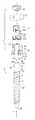
- FIG. 1is an exploded perspective view of a polyaxial bone screw assembly according to the present invention including a shank, a receiver, an open friction fit retainer and a top drop and turn in place lower compression insert, further shown with a portion of a longitudinal connecting member in the form of a rod and a closure top.
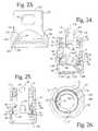
- FIG. 2is an enlarged top plan view of the shank of FIG. 1 .
- FIG. 3is a reduced cross-sectional view taken along the line 3 - 3 of FIG. 2 .
- FIG. 4is an enlarged side elevational view of the receiver of FIG. 1 .
- FIG. 5is a perspective view of the receiver of FIG. 4 .
- FIG. 6is a front elevational view of the receiver of FIG. 4 .
- FIG. 7is a bottom plan view of the receiver of FIG. 4 .
- FIG. 8is a top plan view of the receiver of FIG. 4 .
- FIG. 9is a cross-sectional view taken along the line 9 - 9 of FIG. 8 .
- FIG. 10is a cross-sectional view taken along the line 10 - 10 of FIG. 8 .
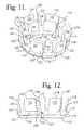
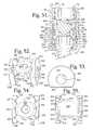
- FIG. 11is an enlarged perspective view of the retainer of FIG. 1 .
- FIG. 12is a front elevational view of the retainer of FIG. 11 .
- FIG. 13is a top plan view of the retainer of FIG. 11 .
- FIG. 14is a bottom plan view of the retainer of FIG. 11 .
- FIG. 15is an enlarged cross-sectional view taken along the line 15 - 15 of FIG. 13 .
- FIG. 16is another perspective view of the retainer of FIG. 11 .
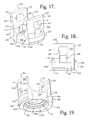
- FIG. 17is an enlarged perspective view of the insert of FIG. 1 .
- FIG. 18is a side elevational view of the insert of FIG. 17 .
- FIG. 19is another perspective view of the insert of FIG. 17 .
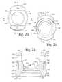
- FIG. 20is a top plan view of the insert of FIG. 17 .
- FIG. 21is a bottom plan view of the insert of FIG. 17 .
- FIG. 22is an enlarged cross-sectional view taken along the line 22 - 22 of FIG. 20 .
- FIG. 23is an enlarged cross-sectional view taken along the line 23 - 23 of FIG. 20 .
- FIG. 24is an enlarged front elevational view of the retainer and receiver of FIG. 1 with portions of the receiver broken away to show the detail thereof, the retainer being shown downloaded into the receiver (in phantom) to a partially inserted stage of assembly.
- FIG. 25is a front elevational view of the retainer and receiver with portions broken away, similar to what is shown in FIG. 24 , showing the retainer in a subsequent stage of assembly and in a maximum state of compression.
- FIG. 26is a bottom plan view of the receiver and retainer of FIG. 25 .
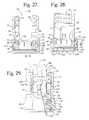
- FIG. 27is an enlarged front elevational view of the retainer and receiver with portions broken away, similar to what is shown in FIG. 25 , showing the retainer positioned below the receiver spring tabs and also rotated about a central axis thereof, such rotation not necessary for assembly but provided herein to aid in viewing the drawings.
- FIG. 28is a cross-sectional view taken along the line 28 - 28 of FIG. 27 .
- FIG. 29is an enlarged front elevational view of the retainer and receiver with portions broken away, similar to what is shown in FIG. 27 , showing the retainer in a slightly lower position within the receiver and further including the insert in side elevation, in phantom, being downloaded into the receiver and the insert shown in solid lines with portions broken away when at a location suitable for rotation within the receiver.
- FIG. 30is a front elevational view of the retainer and receiver with portions broken away, similar to what is shown in FIG. 29 , further showing the insert being partially rotated within the receiver with receiver spring tabs being pushed outwardly during such rotation.
- FIG. 31is a reduced front elevational view with portions broken away, similar to FIG. 30 , showing the insert fully rotated within the receiver with the receiver spring tabs pressing into apertures of the insert and with retainer spring tabs located to push resiliently outwardly against the receiver, holding the retainer against the receiver and keeping the retainer in an upward position during shipping and assembly with the shank of FIG. 1 , the figure further showing the shank of FIG. 1 in an enlarged and partial front elevational view and implanted into a portion of a vertebra, a hemisphere of the shank head and the vertebra portion are both shown in phantom.
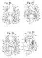
- FIG. 32is an enlarged and partial front elevational view with portions broken away, similar to FIG. 31 , and further showing the shank in a first stage of assembly with the receiver and retainer.
- FIG. 33is an enlarged and partial front elevational view with portions broken away, similar to FIG. 32 , showing the retainer lower portion in an expanded state about a mid-portion of the shank head.
- FIG. 34is a reduced and partial front elevational view with portions broken away, similar to FIG. 33 , the spherical shank upper portion or head shown fully captured by the retainer.
- FIG. 35is a reduced and partial front elevational view with portions broken away, similar to FIG. 34 , the shank upper portion with attached retainer being shown pulled down into a seated position within the lower receiver cavity, the retainer spring tabs in a substantially neutral state, extending outwardly and captured beneath a surface of the receiver.
- FIG. 36is an enlarged and partial front elevational view with portions broken away, similar to FIG. 35 , the insert being shown pushed down into a fully seated position within the lower receiver cavity by pressure being placed thereon from above by the rod and closure top of FIG. 1 , also shown in partial front elevation, the insert being placed in locking interference fit with the receiver.
- FIG. 37is a partial perspective view of the locked assembly of FIG. 36 with portions broken away to show the detail thereof.
- FIG. 38is an enlarged and partial front elevational view with portions broken away, similar to FIG. 36 , but with the locking insert having been pulled slightly upwardly by tooling (not shown) to result in an unlocked polyaxial mechanism.
- FIG. 39is an enlarged and partial front elevational view with portions broken away, similar to FIG. 36 , but shown with the rod and closure top of FIG. 36 having been removed, the locking insert keeping the shank locked in place, the figure further showing an alternative deformable rod and cooperating closure top being installed in the receiver.
- FIG. 40is a reduced and partial front elevational view with portions broken away, similar to FIG. 39 , showing the alternative rod and closure top fixed to the receiver.
- FIG. 41is a reduced side elevational view of the assembly of FIG. 1 , shown fully assembled with the shank disposed at a twenty-two degree (cephalad) angle with respect to the receiver.
- FIG. 42is an enlarged and partial side elevational view of the assembly of FIG. 41 with portions broken away to show the detail thereof.
- FIG. 43is a reduced side elevational view of the assembly of FIG. 1 , shown fully assembled with the shank disposed at a thirty-three degree (caudad) angle with respect to the receiver.
- FIG. 44is a perspective view of the assembly of FIG. 43 .
- FIG. 45is an enlarged and partial side elevational view of the assembly of FIG. 43 with portions broken away to show the detail thereof.
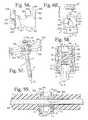
- FIG. 46is an enlarged perspective view of an alternative favored angle receiver according to the invention having opposed lower concave stepped surfaces for cooperating with the retainer of FIG. 1 to allow for up to a forty degree angle of the shank of FIG. 1 with respect to the alternative receiver.
- FIG. 47is an enlarged perspective view of an alternative non-locking insert according to the invention for use in lieu of the locking insert shown in FIG. 1 .
- FIG. 48is another enlarged perspective view of the alternative insert of FIG. 47 with a portion broken away to show the detail thereof.
- FIG. 49is a side elevational view of the alternative insert of FIG. 47 with a portion broken away to show the detail thereof.
- FIG. 50is an enlarged front elevational view of the receiver and retainer of FIG. 1 shown in a stage of assembly with the alternative insert of FIG. 47 , also in front elevation, with portions broken away to show the detail thereof.
- FIG. 51is an enlarged and partial front elevational view of the receiver, retainer, rod and closure top of FIG. 1 shown fully assembled with the alternative insert of FIG. 47 , also in front elevation, with portions broken away to show the detail thereof.
- FIG. 52is a perspective view of a sleeve according to the invention for use with bone screw assemblies of the invention.
- FIG. 53is a front elevational view of the sleeve of FIG. 52 .
- FIG. 54is a top plan view of the sleeve of FIG. 52 .
- FIG. 55is a bottom plan view of the sleeve of FIG. 52 .
- FIG. 56is a side elevational view of the sleeve of FIG. 52 with portions broken away to show the detail thereof.
- FIG. 57is a reduced perspective view of the sleeve of FIG. 52 shown assembled with a bone screw assembly of FIG. 1 (shown partially exploded), with the rod of FIG. 1 being replaced by a cord, and further showing a pair of transparent compressible cylindrical spacers located about the cord and at either side of the sleeve.
- FIG. 58is an enlarged cross-sectional view taken along the line 58 - 58 of FIG. 57 with the closure top shown mated with the receiver.
- FIG. 59is a reduced cross-sectional view taken along the line 59 - 59 of FIG. 58 .
- FIG. 60is a partially exploded, front elevational view of the sleeve of FIG. 52 and bone screw assembly of FIG. 1 , but with the rod and closure top of FIG. 1 being replaced by a cord and an alternative cord-locking closure top.
- FIG. 61is a front elevational view, similar to FIG. 60 , with portions broken away to show the detail thereof, showing the alternative cord-locking closure top engaging the sleeve and the receiver.
- FIG. 62is an enlarged and partial, perspective view of the assembly shown in FIG. 57 , but with one of the spacers being replaced with a bumper (shown transparent) and blocker/set screw combination, shown partially exploded.
- FIG. 63is an enlarged and partial side elevational view of the assembly of FIG. 62 with portions broken away to show the detail thereof, showing the set screw fixing the cord with respect to the blocker and the cord in slidable relationship with the bone screw.
- FIG. 64is an enlarged perspective view of the assembly of FIG. 1 , but with the rod and closure top of FIG. 1 being replaced by a second alternative sleeve with rectangular faces, a cord and alternative cord-locking closure top of the invention.
- FIG. 65is a partial and partially exploded front elevational view of the assembly of FIG. 64 .
- FIG. 66is an enlarged and partial front elevational view of the assembly of FIG. 64 with portions broken away to show the detail thereof.
- FIG. 67is an enlarged perspective view of the alternative sleeve of FIG. 64 .
- FIG. 68is a top plan view of the alternative sleeve of FIG. 67 .
- FIG. 69is a bottom plan view of the alternative sleeve of FIG. 67 .
- FIG. 70is a side elevational view of the alternative sleeve of FIG. 67 with portions broken away to show the detail thereof.
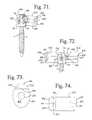
- FIG. 71is a reduced perspective view of the assembly of FIG. 64 further shown with an alternative compressible spacer having an oval profile (shown transparent).
- FIG. 72is a partial side elevational view of the assembly of FIG. 71 further shown with a second alternative compressible spacer with an oval profile (also shown transparent).
- FIG. 73is an enlarged front elevational view of the compressible spacer with oval profile shown in FIG. 71 .
- FIG. 74is a top plan view of the spacer of FIG. 73 .
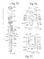
- FIG. 75is an exploded perspective view of an alternative polyaxial bone screw assembly according to the present invention including a shank, a receiver, an open friction fit retainer and a top drop and turn in place lower compression insert, further shown with a portion of a longitudinal connecting member in the form of a rod and a closure top.
- FIG. 76is an enlarged side elevational view of the receiver of FIG. 75 .
- FIG. 77is a reduced front elevational view of the receiver of FIG. 76 .
- FIG. 78is a cross-sectional view taken along the line 78 - 78 of FIG. 76 .
- FIG. 79is an enlarged cross-sectional view taken along the line 79 - 79 of FIG. 77 .
- FIG. 80is an enlarged front elevational view of the retainer of FIG. 75 .
- FIG. 81is an enlarged and partial front elevational view of the retainer of FIG. 80 .
- FIG. 82is a perspective view of the retainer of FIG. 80 .
- FIG. 83is another perspective view of the retainer of FIG. 80 .
- FIG. 84is a top plan view of the retainer of FIG. 80 .
- FIG. 85is a bottom plan view of the retainer of FIG. 80 .
- FIG. 86is an enlarged cross-sectional view taken along the line 86 - 86 of FIG. 84 .
- FIG. 87is an enlarged perspective view of the insert of FIG. 75 .
- FIG. 88is a side elevational view of the insert of FIG. 87 with portions broken away to show the detail thereof.
- FIG. 89is a front elevational view of the insert of FIG. 87 with portions broken away to show the detail thereof.
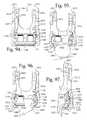
- FIG. 90is an enlarged front elevational view of the retainer and receiver of FIG. 75 with portions of the receiver broken away to show the detail thereof, the retainer being shown downloaded into the receiver to a partially inserted stage of assembly.
- FIG. 91is a perspective view of the retainer and receiver with portions broken away, similar to what is shown in FIG. 90 , showing the retainer in a subsequent stage of assembly and in a maximum state of compression.
- FIG. 92is a front elevational view of the retainer and receiver with portions broken away, similar to what is shown in FIG. 91 , showing the retainer positioned below the receiver spring tabs and also rotated about a central axis thereof, such rotation not necessary for assembly but provided herein to aid in viewing the drawings.
- FIG. 93is an enlarged front elevational view of the retainer and receiver with portions broken away, similar to what is shown in FIG. 27 , showing the retainer fully deployed within the receiver cavity and further including the insert in side elevation, being downloaded into the receiver and at a location suitable for rotation within the receiver.
- FIG. 94is a front elevational view of the retainer and receiver with portions broken away, similar to what is shown in FIG. 93 , further showing the insert being rotated to a desired position in the receiver with the receiver spring tabs pressing into apertures of the insert and further showing the retainer tangs being squeezed (tool not shown) in preparation for moving the retainer upwardly toward the insert.
- FIG. 95is a front elevational view of the retainer and receiver with portions broken away, similar to what is shown in FIG. 94 , the retainer shown in a position wherein the tangs push resiliently outwardly against the receiver, holding the retainer against the receiver and keeping the retainer in an upward position during shipping and assembly with the shank of FIG. 75 , the figure further showing the shank of FIG. 75 in an enlarged and partial front elevational view at an early stage of assembly with the retainer, a hemisphere of the shank head is shown in phantom.
- FIG. 96is an enlarged and partial front elevational view with portions broken away, similar to FIG. 95 , showing the retainer lower portion in an expanded state about a mid-portion of the shank head.
- FIG. 97is an enlarged and partial front elevational view with portions broken away, similar to FIG. 96 , the spherical shank upper portion or head shown fully captured by the retainer.
- FIG. 98is a reduced and partial front elevational view with portions broken away, similar to FIG. 97 , the shank upper portion with attached retainer being shown pulled down into a seated position within the lower receiver cavity, the retainer tangs in a substantially neutral state, extending outwardly and captured beneath a surface of the receiver.
- FIG. 99is a reduced and partial front elevational view with portions broken away, similar to FIG. 98 , the insert being shown pushed down into a fully seated position within the lower receiver cavity by pressure being placed thereon from above by the rod and closure top of FIG. 75 , also shown in partial front elevation, the insert being placed in locking interference fit with the receiver.
- FIG. 100is an enlarged and partial front elevational view with portions broken away of the assembly as shown in FIG. 99 .
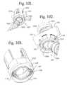
- FIG. 101is an enlarged and partial perspective view of the assembly of FIG. 75 , shown fully assembled with the shank disposed at a twenty degree (cephalad) angle with respect to the receiver.
- FIG. 102is an enlarged and partial perspective view of the assembly of FIG. 75 , shown fully assembled with the shank disposed at a thirty degree (caudad) angle with respect to the receiver.
- FIG. 103is an enlarged perspective view of an alternative favored angle receiver according to the invention having opposed lower concave stepped surfaces, shown cooperating with the retainer of FIG. 75 .
- FIG. 104is an enlarged perspective view of an alternative non-locking insert according to the invention for use in lieu of the locking insert shown in FIG. 75 .
- FIG. 105is an enlarged front elevational view of the alternative insert of FIG. 104 shown in a stage of assembly with the receiver and retainer of FIG. 75 , with portions broken away to show the detail thereof.
- FIG. 106is an enlarged and partial front elevational view of the receiver, retainer, rod and closure top of FIG. 75 shown fully assembled with the alternative insert of FIG. 104 , also in front elevation, with portions broken away to show the detail thereof.
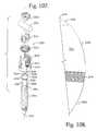
- FIG. 107is an exploded perspective view of another alternative polyaxial bone screw assembly according to the present invention including a shank, a receiver, an open friction fit retainer and a top drop and turn in place lower compression insert, further shown with a portion of a longitudinal connecting member in the form of a rod and a closure top.
- FIG. 108is an enlarged and partial front elevational view of the shank of FIG. 107 .
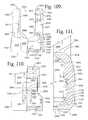
- FIG. 109is an enlarged front elevational view of the receiver of FIG. 107 with portions broken away to show the detail thereof.
- FIG. 110is side elevational view of the receiver of FIG. 109 with portions broken away to show the detail thereof.
- FIG. 111is an enlarged an partial front elevational view of the receiver of FIG. 109 .
- FIG. 112is an enlarged perspective view of the retainer of FIG. 107 .
- FIG. 113is a top plan view of the retainer of FIG. 112 .
- FIG. 114is a reduced bottom plan view of the retainer of FIG. 112 .
- FIG. 115is a reduced cross-sectional view taken along the line 115 - 115 of FIG. 113 .
- FIG. 116is a reduced cross-sectional view taken along the line 116 - 116 of FIG. 113 .
- FIG. 117is an enlarged front elevational view of the insert of FIG. 107 with portions broken away to show the detail thereof.
- FIG. 118is a side elevational view of the insert of FIG. 117 with portions broken away to show the detail thereof.
- FIG. 119is an enlarged front elevational view of the retainer and receiver of FIG. 107 with portions of the receiver broken away to show the detail thereof, the retainer being shown downloaded into the receiver to a partially inserted stage of assembly.
- FIG. 120is a perspective view of the retainer and receiver with portions broken away, similar to what is shown in FIG. 119 , showing the retainer in a subsequent stage of assembly and in a maximum state of compression.
- FIG. 121is a front elevational view of the retainer and receiver with portions broken away, similar to what is shown in FIG. 119 , showing the retainer tangs fully deployed within the receiver cavity, but the retainer not fully seated within the receiver cavity.
- FIG. 122is an enlarged and partial front elevational view of the assembly as shown in FIG. 121 .
- FIG. 123is a front elevational view of the retainer and receiver with portions broken away, similar to FIG. 121 and further including the insert in side elevation, being downloaded into the receiver and at a location suitable for rotation within the receiver.
- FIG. 124is a reduced front elevational view of the retainer and receiver with portions broken away, similar to what is shown in FIG. 123 , further showing the insert being rotated to a desired position in the receiver with the receiver spring tabs pressing into apertures of the insert and further showing the shank of FIG. 107 in an enlarged and partial front elevational view at an early stage of assembly with the retainer.
- FIG. 125is an enlarged and partial front elevational view with portions broken away, similar to FIG. 124 , showing the retainer lower portion in an expanded state about a mid-portion of the shank head.
- FIG. 126is an enlarged and partial front elevational view with portions broken away, similar to FIG. 125 , the spherical shank upper portion or head shown fully captured by the retainer and the shank head being shown pressing up against the insert.
- FIG. 127is a reduced and partial front elevational view with portions broken away, similar to FIG. 126 , the shank upper portion being shown partially pulled down into the receiver cavity, the retainer outer tangs in a substantially neutral state and the inner tangs contacting ridges on the shank head.
- FIG. 128is an enlarged and partial front elevational view with portions broken away, similar to FIG. 127 , showing a further pull-down of the shank head with respect to inner retainer tangs.
- FIG. 129is an enlarged and partial front elevational view with portions broken away, similar to FIG. 128 , showing a further pull-down of the shank head and attached retainer, the retainer being pulled down to a seated position within the receiver cavity.
- FIG. 130is a reduced and partial front elevational view with portions broken away, similar to FIG. 129 , the insert being pushed down into a fully seated position within the lower receiver cavity by pressure being placed thereon from above by the rod and closure top of FIG. 107 , also shown in partial front elevation, the insert being placed in locking interference fit with the receiver.
- FIG. 131is an enlarged and partial front elevational view with portions broken away of the assembly of FIG. 130 , but with the closure top loosened and the rod lifted up, the insert however remaining locked into place against the receiver, maintaining the retainer and shank in a locked position.
- FIG. 132is a reduced and partial front elevational view with portions broken away of the assembly of FIG. 131 with the exception that the rod and closure top have been removed and replaced with an alternative deformable rod and cooperating alternative closure top.
- FIG. 133is an enlarged and partial perspective view of the assembly of FIG. 107 , shown fully assembled with the shank disposed at a twenty degree (cephalad) angle with respect to the receiver.
- FIG. 134is an enlarged and partial perspective view of the assembly of FIG. 107 , shown fully assembled with the shank disposed at a thirty degree (caudad) angle with respect to the receiver.
- FIG. 135is an enlarged perspective view of an alternative non-locking insert according to the invention for use in lieu of the locking insert shown in FIG. 107 .
- FIG. 136is an enlarged front elevational view of the alternative insert of FIG. 135 shown in a stage of assembly with the receiver and retainer of FIG. 107 , with portions broken away to show the detail thereof.
- FIG. 137is an enlarged and partial front elevational view of the receiver, retainer, rod and closure top of FIG. 107 shown fully assembled with the alternative insert of FIG. 135 , also in front elevation, with portions broken away to show the detail thereof.
- the reference number 1generally represents a polyaxial bone screw apparatus or assembly according to the present invention.
- the assembly 1includes a shank 4 , that further includes a body 6 integral with an upwardly extending upper portion or head 8 ; a receiver 10 ; a friction fit retainer 12 , and a crown-like compression or pressure insert 14 .
- the receiver 10 , retainer 12 and compression insert 14are initially assembled and may be further assembled with the shank 4 either prior or subsequent to implantation of the shank body 6 into a vertebra 17 , as will be described in greater detail below.
- the receiver 10 and the shank 4cooperate in such a manner that the receiver 10 and the shank 4 can be secured at any of a plurality of angles, articulations or rotational alignments relative to one another and within a selected range of angles both from side to side and from front to rear, to enable flexible or articulated engagement of the receiver 10 with the shank 4 until both are locked or fixed relative to each other near the end of an implantation procedure.
- the illustrated rod 21is hard, stiff, non-elastic and cylindrical, having an outer cylindrical surface 22 .
- the rod 21may be elastic, deformable and/or of different materials and cross-sectional geometries (see, e.g., FIGS. 39 and 40 ). It is foreseen that in other embodiments (not shown) the closure top could deform the rod and press directly on the insert 14 .
- the shank 4is elongate, with the shank body 6 having a helically wound bone implantable thread 24 (single or dual lead thread form and different thread types) extending from near a neck 26 located adjacent to the upper portion or head 8 , to a tip 28 of the body 6 and extending radially outwardly therefrom.
- the body 6utilizing the thread 24 for gripping and advancement is implanted into the vertebra 17 leading with the tip 28 and driven down into the vertebra with an installation or driving tool (not shown), so as to be implanted in the vertebra to a location at or near the neck 26 , as shown in FIG. 31 , for example, and more fully described in the paragraphs below.
- the shank 4has an elongate axis of rotation generally identified by the reference letter A.
- the neck 26extends axially upward from the shank body 6 .
- the neck 26may be of the same or is typically of a slightly reduced radius as compared to an adjacent upper end or top 32 of the body 6 where the thread 24 terminates.
- the shank upper portion or head 8Further extending axially and outwardly from the neck 26 is the shank upper portion or head 8 that provides a connective or capture apparatus disposed at a distance from the upper end 32 and thus at a distance from the vertebra 17 when the body 6 is implanted in such vertebra.
- the shank upper portion 8is configured for a pivotable connection between the shank 4 and the retainer 12 and receiver 10 prior to fixing of the shank 4 in a desired position with respect to the receiver 10 .
- the shank upper portion 8has an outer, convex and substantially spherical surface 34 that extends outwardly and upwardly from the neck 26 that in some embodiments terminates at a substantially a circular or polygonal edge or rim 38 .
- a frusto-conical surface 39extends from the spherical surface 34 inwardly to the top edge 38 , providing additional clearance during pivoting of the shank with respect to the receiver 10 and the insert 14 .
- the spherical surface 34has an outer radius configured for temporary frictional, non-floppy, sliding cooperation with one or more edges and/or surfaces of the retainer 12 , as well as ultimate frictional engagement with the retainer 12 at a lower inner edge thereof and ultimate frictional engagement with the insert 14 at an inner partially spherical surface thereof and/or stepped or ridged surfaces thereof, as will be discussed more fully in the paragraphs below.
- a dotted line 40designates a hemisphere of the spherical surface 34 .
- the spherical surface 34 shown in the present embodimentis substantially smooth, but in some embodiments may include a roughening or other surface treatment and is sized and shaped for cooperation and ultimate frictional engagement with the compression insert 14 as well as ultimate frictional engagement with a lower ring-like edge of the retainer 12 .
- the shank spherical surface 34is locked into place exclusively by the insert 14 and the retainer 12 lower edged portion and not by inner surfaces defining the receiver cavity.
- a counter sunk and stepped or graduated annular seating surface or base 45partially defines a portion of an internal drive feature or imprint 46 .
- the surface 45is substantially planar.
- the illustrated internal drive feature 46is an aperture formed in the top 38 and has a hex shape designed to receive a tool (not shown) of an Allen wrench type, into the aperture for rotating and driving the bone screw shank 4 into the vertebra 17 . It is foreseen that such an internal tool engagement structure may take a variety of tool-engaging forms and may include one or more apertures of various shapes, such as a pair of spaced apart apertures or a multi-lobular or star-shaped aperture.
- the graduated seat or base surfaces 45 of the drive feature 46are disposed substantially perpendicular to the axis A with the drive feature 46 otherwise being coaxial with the axis A.
- the drive seat 45 having beveled or stepped surfacesadvantageously further enhances gripping with the driving tool.
- the driving tool(not shown) is received in the internal drive feature 46 , being seated at the base 45 and engaging the faces of the drive feature 46 for both driving and rotating the shank body 6 into the vertebra 17 , either before or after the shank 4 is connected to the receiver 10 via the retainer 12 , the driving tool extending into the receiver 10 when the shank 4 , retainer 12 and receiver 10 combination is driven into the vertebra 17 .
- the shank 4 shown in the drawingsis cannulated, having a small central bore 50 extending an entire length of the shank 4 along the axis A.
- the bore 50is defined by an inner cylindrical wall of the shank 4 and has a circular opening at the shank tip 28 and an upper circular opening communicating with the external drive 46 at the driving seat 45 .
- the bore 50is coaxial with the threaded body 6 and the upper portion or head 8 .
- the bore 50provides a passage through the shank 4 interior for a length of wire (not shown) inserted into the vertebra 17 prior to the insertion of the shank body 6 , the wire providing a guide for insertion of the shank body 6 into the vertebra 17 .
- the shankcould be solid and made of different materials, including metal and non-metals.
- the threaded shank body 6may be coated, perforated, made porous or otherwise treated.
- the treatmentmay include, but is not limited to a plasma spray coating or other type of coating of a metal or, for example, a calcium phosphate; or a roughening, perforation or indentation in the shank surface, such as by sputtering, sand blasting or acid etching, that allows for bony ingrowth or ongrowth.
- Certain metal coatingsact as a scaffold for bone ingrowth.
- Bio-ceramic calcium phosphate coatingsinclude, but are not limited to: alpha-tri-calcium phosphate and beta-tri-calcium phosphate (Ca 3 (PO 4 ) 2 , tetra-calcium phosphate (Ca 4 P 2 O 9 ), amorphous calcium phosphate and hydroxyapatite (Ca 10 (PO 4 ) 6 (OH) 2 ).
- Coating with hydroxyapatitefor example, is desirable as hydroxyapatite is chemically similar to bone with respect to mineral content and has been identified as being bioactive and thus not only supportive of bone ingrowth, but actively taking part in bone bonding.
- the receiver 10has a generally U-shaped appearance with partially discontinuous cylindrical inner and outer profiles as well as planar and other curved surfaces.
- the receiver 10has an axis of rotation B that is shown in FIG. 1 as being aligned with and the same as the axis of rotation A of the shank 4 , such orientation being desirable, but not required during assembly of the receiver 10 with the shank 4 .
- the axis Bis typically disposed at an angle with respect to the axis A, as shown, for example, in FIGS. 41-46 .
- the receiver 10includes a base 60 with various curved and mostly cylindrical surfaces 58 and opposed outer planar surfaces 59 , the base 60 defining a bore or inner cavity, generally 61 , the base 60 being integral with a pair of opposed upstanding arms 62 .
- the planar surfaces 59are located between the arms 62 and an inset surface portion 63 is located above and adjacent to each planar surface 59 , each inset surface portion 63 spanning between the pair of arms 62 .
- the arms 62form a cradle and define a U-shaped channel 64 between the arms 62 with an upper opening, generally 66 , and a U-shaped lower channel portion or seat 68 , the channel 64 having a width for operably snugly receiving the rod 21 or portion of another longitudinal connector or sleeve (such as those shown in FIGS. 52-74 ) between the arms 62 , the channel 64 communicating with the base cavity 61 .
- Inner opposed substantially planar arm surfaces 69partially define the channel 64 above the curved seat 68 and partially define outer sides of each arm interior surface generally 70 , that includes various inner cylindrical profiles, an upper one of which is a partial helically wound guide and advancement structure 72 located adjacent top surfaces 73 of each of the arms 62 .
- the guide and advancement structure 72is a partial helically wound interlocking flangeform configured to mate under rotation with a similar structure on the closure structure 18 , as described more fully below.
- the guide and advancement structure 72could alternatively be a square-shaped thread, a buttress thread, a reverse angle thread or other thread-like or non-thread-like helically wound discontinuous advancement structures, for operably guiding under rotation and advancing the closure structure 18 downward between the arms 62 , as well as eventual torquing when the closure structure 18 abuts against the rod 21 or other longitudinal connecting member.
- the arms 62could have break-off extensions.
- An opposed pair of circular tool receiving and engaging apertures 74are formed on outer substantially cylindrical surfaces 76 of the arms 62 near the top surfaces 73 . Furthermore, below each aperture 74 is a through aperture or bore 77 also formed in and through each of the outer surfaces 76 , each aperture 77 having a generally up-side down U-shape, the U-shape aperture defining a central inwardly and upwardly extending holding tab 78 integral with the respective arm 62 at or near the base 60 , generally extending upwardly from the receiver base 60 and inwardly toward the receiver axis B. Each aperture 77 extends through the respective arm surface 76 to the respective inner arm surface 70 . Each aperture 77 is located spaced from the adjacent aperture 74 and near or adjacent the receiver base 60 .
- apertures 74 and 77may be used for holding the receiver 10 during assembly with the insert 14 , the retainer 12 and the shank 4 , during the implantation of the shank body 6 into a vertebra when the shank is pre-assembled with the receiver 10 , and during assembly of the bone anchor assembly 1 with the rod 21 or other longitudinal connecting member and the closure structure 18 . It is foreseen that tool receiving grooves or apertures may be configured in a variety of shapes and sizes and be disposed at other locations on the receiver arms 62 .
- the assembly 1is typically provided to a user with the insert 14 being held within the receiver by the pair of inwardly extending holding tabs 78 , that are typically somewhat resilient, firmly holding the insert 14 during assembly with the shank 4 and keeping the insert 14 relatively stationary with respect to the receiver 10 in an upward position between the arms 62 until the insert 14 is pressed downwardly into locking friction fit with the shank upper portion or head 8 .
- the holding tabs 78advantageously hold the insert 14 in a centered position (the insert arms being held in alignment with the receiver arms) during rotation and torquing of the closure top 18 onto the rod 21 or other connecting member.
- the opposed holding tabs 78include outer surfaces and also various inner surfaces for contacting the insert 14 .
- the tab surfacesinclude a first outer surface 80 extending from the base 60 and sloping upwardly and slightly inwardly toward the receiver axis B.
- a second inwardly sloping surface 81is adjacent to the surface 80 and is directed toward the axis B at an angle with respect thereto.
- the surface 81generally extends between the receiver outer periphery to the inner arm surface 70 .
- Adjacent to the surface 81is a tab top surface 82 that runs toward the axis B and is substantially perpendicular thereto.
- An inner insert engaging surface 84is substantially perpendicular to the top surface 82 .
- the surface 84is adjacent to a lower tab surface 85 and is perpendicular thereto.
- the insert engaging surface 84is illustrated as having a slightly concave or cylindrical shape (may also be planar), sized and shaped for engagement with an outer substantially cylindrical surface of the insert 14 as will be described in greater detail below.
- the lower surface 85is parallel to the top surface 82 .
- the holding tabs 78are stable, but exhibit some resilience, being pushed outwardly away from the axis B during rotation of the insert 14 when the insert 14 is being assembled with the receiver 10 as shown, for example, in FIG. 30 .
- Each holding tab 78further includes opposed side surfaces 88 that partially define the U-shaped portion of the through aperture 77 .
- the aperture 77is further defined by a top surface 89 , opposed outer substantially planar side surfaces 90 and a pair of spaced, curved bottom surfaces 91 .
- a discontinuous cylindrical surface 92partially defining a run-out feature for the guide and advancement structure 72 .
- the cylindrical surface 92is sized and shaped to receive the insert 14 as will be described in greater detail below.
- the surface 92has a diameter slightly greater than a greater diameter of the guide and advancement structure 72 .
- the illustrated receiver 10further includes sloped, stepped or chamfered surface above and below the surface 92 .
- the surface 92is divided not only by the U-shaped channel 64 , but also by each of the through apertures 77 .
- a lower partially sloping or stepped ledge 94 at the base of the cylindrical surface 92slopes downwardly toward the receiver base 60 and extends inwardly toward the axis B, the surface 94 terminating at a cylindrical surface 95 that extends completely around the receiver base 60 and thus runs beneath each arm 62 and is adjacent to the lower seat 68 .
- the inner surface 95thus defines an upper and inner portion of the receiver base 60 .
- the cylindrical surfacehas a diameter slightly smaller than the diameter of the surface 92 . Lower legs of the through aperture 77 partially defined by the surfaces 88 extend through the surface 95 .
- the surface 95terminates at a ledge surface or chamber ceiling 96 that extends outwardly away from the axis B, the surface 96 being substantially perpendicular to the axis B, but could be oblique.
- the surface 96is annular and defines an upper ceiling or stop of a retainer ring expansion portion or chamber of the inner cavity 61 that is further defined by an adjacent outwardly sloping surface 97 and a cylindrical surface 98 that is adjacent the surface 97 .
- the surface 97acts as a stop for and slidingly cooperates with outwardly and upwardly projecting retainer tangs or panels as will be described in greater detail below.
- the cylindrical surface 98has a diameter greater than the diameter of the cylindrical surface 95 .
- the cylindrical surfaces 92 , 95 and 98are all centrally aligned with and run parallel to the receiver axis B.
- Lower surface portions 91 that define the through aperture 77extend into and through the sloping surface 97 .
- the surface 98defines a circumferential recess that is sized and shaped to receive the retainer 12 as it expands around the shank upper portion 8 as the shank 8 moves upwardly toward the channel 64 during assembly. It is foreseen that the recess could be tapered or conical in configuration.
- a pair of cylindrical surfaces 100 and 101 with an annular step surface 102 therebetween as well as a lower annular step 103 located below and adjacent to the surface 101provide a lower seat for the retainer 12 as will be described in greater detail below.
- the surfaces 102 and 103are substantially perpendicular to the surfaces 100 and 101 and the receiver axis B.
- the surfaces 100 , 101 , 102 and 103are located below the cylindrical surface 98 in the lower part of the base 60 and are sized and shaped to closely receive and surround a lower base portion and lower skirt or sub-structure of the retainer 12 when the retainer is in a reduced deployment position as shown in FIGS. 35-38 , for example.
- the cylindrical surface 101has a diameter smaller than the diameter of the cylindrical surface 98 that defines the expansion area or expansion chamber for the retainer 12 .
- the surface 101is joined or connected to the surface 98 by one or more beveled, curved or conical transition step surfaces 104 .
- the surfaces 104allow for sliding and nominal or deployment positioning of the retainer 12 into the space defined by the surfaces 100 and 101 and ultimate seating of the retainer 12 on the lower substantially horizontal annular surfaces 102 and 103 .
- a lower edge or rim surface 106that communicates with a beveled or flared bottom opening surface 107 , the surface 107 communicating with an exterior base or bottom surface 108 of the base 60 , defining a lower opening, generally 110 , into the base cavity 61 of the receiver 10 .
- a curvate cut-out or cupped surfacemay be formed in a portion of the base surface 108 , as well as in portions of the surfaces 107 , 106 and 100 - 104 located substantially centrally and directly below one of the arms 62 .
- Such a cupped surfacemay be sized and shaped for providing clearance for an increased angle of articulation between the shank 4 and the receiver 10 .
- the lower open or split friction fit retainer 12that operates to capture the shank upper portion 8 within the receiver 10 is shown.
- the retainer 12is partially constrained within the receiver, being captured within the receiver cavity 61 at a location below the surface 97 , the retainer 12 being rotatable with respect to the receiver, but not pivotable thereto and not readily removable out of the receiver once deployed downward into the receiver cavity 61 .
- the retainer 12has a central axis that is operationally the same as the axis B associated with the receiver 10 when the shank upper portion 8 and the retainer 12 are installed within the receiver 10 .
- the retainer 12includes a substantially annular discontinuous body 115 having a substantially cylindrical outer surface 116 . Extending upwardly and outwardly from the body 115 , and integral thereto, is a superstructure that includes two sets of flexible panels or tangs, in particular, inner panels or tangs 117 and outer panels or tangs 118 , the panels 117 and 118 extending upwardly in aligned pairs, allowing for lateral spaces between the pairs panels or tangs to provide clearance during assembly of the retainer 12 with the receiver 10 inner surfaces (see, e.g., FIGS. 24 and 25 ).
- the illustrated embodimentincludes six pairs of inner and outer panels or tangs 117 , 118 , but it is foreseen that more or fewer panels or tangs may be used.
- the pairs of panels or tangsare generally equally spaced about the body 115 .
- Also integral to the body 115are six outer discontinuous cylindrical support surfaces 120 , each surface 120 located beneath one of the outer panels 118 .
- Below the surfaces 120the cylindrical surface 116 forms a lower outer cylindrical skirt 121 broken only by a gap that will be described in greater detail below.
- the outer surface 116is adjacent a bottom surface 122 and also includes portions 123 that are located between the outer panels 118 .
- the surface portions 123are illustrated as substantially planar, but may be cylindrical, generally having a diameter that is the same as the surface 116 .
- the surface 116is adjacent to a ledge surface 124 that in turn is adjacent to one of the outer support surfaces 120 .
- the lower skirt 121 and the ledge surfaces 124 , as well as the surfaces 120are receiver seating surfaces as will be described in greater detail below.
- transition areas where the surface 116 meets the panels 117 and 118 or the retainer bottom 122are curved or chamfered.
- Each body portion 123is adjacent to a body top surface 126 that is substantially located between pairs of panels 117 and 118 .
- Each top surface portion 126is substantially planar and trapezoidal in outer profile.
- the inner panels 117each include a substantially planar outer surface 128 and a concave inner surface 129 , the surfaces 129 each being partially radiused and partially cylindrical, making up a discontinuous curved surface sized and shaped for friction fit engagement with the shank head 8 as best shown in FIG. 13 and as will be described in greater detail below.
- the panel inner surfaces 129may also be planar or include edges or other surfaces features for gripping, but not locking the retainer 12 to the shank head 8 during assembly and manipulation, but prior to locking of the polyaxial mechanism of the bone screw assembly 1 .
- the panels 117generally slant inwardly towards the central axis of the retainer 12 and thus ultimately inwardly toward the shank head 8 .
- Each panel 117includes a top surface 130 that is substantially planar and runs substantially parallel to the bottom surface 122 when the retainer is in a neutral position such as that shown in FIG. 15 .
- the outer panels 118each have a planar outer surface 132 , a planar inner surface 133 and a planar top surface 134 that slopes at an oblique angle with respect to the retainer bottom surface 122 .
- the surfaces 134are perpendicular to adjacent surfaces 132 .
- the panels 118generally extend outwardly away from the panels 117 as well as outwardly and upwardly from the central axis of the retainer body 115 .
- Each surface 133faces an outer surface 128 of one of the panels 117 .
- the body top surface 126is reduced to a narrow strip between each pair of panels 117 and 118 .
- the panels 117 and 118are resilient, the panels being expandable about the shank head 8 and the panels 118 being compressible inwardly and resiliently holding against the receiver inner surfaces during shipping and certain assembly steps. The panels 118 then return to an original shape within the receiver cavity 61 , capturing the retainer 12 within the receiver 10 , but still allowing for rotation of the retainer 12 with respect to the receiver 10 about the receiver central axis B.
- the retainer ring 12is made from a resilient material, such as a stainless steel or titanium alloy, so that the retainer 12 body 115 may be expanded and the tabs or panels 117 and 118 of the retainer may be manipulated during various steps of assembly as will be described in greater detail below.
- the retainer 12has a central channel or hollow through bore, generally 141 , that passes entirely through the retainer 12 from the inner panel top surfaces 130 to the bottom surface 122 of the retainer body 115 .
- Surfaces that define the channel or bore 141 at the body 115include a discontinuous inner lower frusto-conical surface 143 adjacent to the retainer body bottom surface 122 , a discontinuous, narrow substantially cylindrical surface 145 adjacent the frusto-conical surface 143 and a discontinuous annular step 146 located adjacent the cylindrical surface 145 , the surface 146 being substantially parallel to the bottom surface 122 and extending between the surface 145 and a lower cylindrical portion 129 ′ of the inner surface 129 that partially forms the inner panels 117 .
- the surfaces 145 and 146terminate at an edge 147 that is positioned and configured to engage the shank surface 34 as will be described in greater detail below.
- the inner cylindrical surface 129 ′ adjacent the step 146forms a continuous inner cylindrical wall except at a slit, generally 148 that runs through the body 115 .
- the slit 148creates a split or open ring retainer 12 , the slit cutting entirely through the retainer body 115 . In some embodiments, such a slit may run obtuse to the bottom surface 122 . In the illustrated embodiment, the slit 148 runs substantially perpendicular to the surfaces 122 .
- the slit 148is primarily for expansion of the retainer 12 during pop-on or snap-on assembly with the shank head 8 . However, the slit 148 also compresses during assembly with the receiver 10 as will be described in greater detail below.
- the slit 148extends between the body top surface 126 and the bottom surface 122 and is located substantially centrally between two pairs of panels 117 and 118 . Furthermore, at the location of the slit 148 , a curved concave, cut-out surface 149 is formed in the bottom surface 122 and the frusto-conical surface 143 . The cut-out surface 149 also extends into the cylindrical surface 145 and removes a portion of the step 146 at either side of the slit 148 . The surface 149 is radiused or otherwise curved for engagement with the shank head 8 at the surface 34 as will be described in greater detail below.
- the cut-out surface 149is located substantially equally on either side of the slit 148 to provide for a desirable increased angle of orientation between the shank 8 and the retainer 12 and thus a desirable increased angle of articulation between the shank 8 and the receiver 10 .
- the rotatability of the semi-constrained retainer 12 with respect to the receiver 10allows for manipulation and placement of such an increased angle of articulation to a location desired by a surgeon.
- the through slit 148 of the resilient retainer 12is defined by first and second end surfaces, 152 and 153 disposed in substantially parallel spaced relation to one another when the retainer is in a neutral or nominal state.
- Both end surfaces 152 and 153are disposed perpendicular to the bottom surface 122 , but in some embodiments may be disposed at an obtuse angle thereto.
- a width between the surfaces 152 and 153is narrow to provide stability to the retainer 12 during operation, but wide enough to allow for some compression of the retainer during assembly as will be described in greater detail below. Because the retainer 12 is top loadable in a substantially neutral state and ultimately expands during locking of the polyaxial mechanism, the width of the slit 148 may be much smaller than might be required for a bottom loaded compressible retainer ring.
- the retainer 12may return to a new nominal or neutral orientation in which a gap between the surfaces 152 and 153 is slightly greater than the gap shown in the nominal state of FIG. 12 , for example.
- the assembly 1advantageously provides for access to the insert 14 and the retainer 12 to allow for pressing of the retainer 12 down onto the receiver seat portions and reducing the retainer 12 into the receiver 10 inner cylindrical surfaces as desired, prior to locking of the assembly 1 with a rod and closure top.
- the locking compression insert 14is illustrated that is sized and shaped to be received by and down-loaded into the receiver 10 at the upper opening 66 .
- the compression insert 14has an operational central axis that is the same as the central axis B of the receiver 10 .
- the insertadvantageously frictionally engages the bone screw shank upper portion 8 as well as engaging the receiver 10 in an interference fit engagement, locking the shank 4 in a desired angular position with respect to the receiver 10 that remains in such locked position even if, for example, a rod and closure top are later removed and the rod is replaced with another rod or other longitudinal connecting member or member component, such as one of the sleeves shown in FIGS. 52-72 .
- Such locked positionmay also be released by the surgeon if desired with insert engaging tools (not shown).
- insert engaging toolsnot shown.
- the insertdoes not have the receiver interference fit feature.
- the locking insert 14 as well as the non-locking insert 214are preferably made from a solid resilient material, such as a stainless steel or titanium alloy, so that portions of the insert may be grasped, pinched or pressed, if necessary, and un-wedged from the receiver 10 with a release tool (not shown).
- the locking compression insert 14includes a body 156 with cylindrical surfaces of a variety of diameters, the body 156 being integral with a pair of upstanding arms 157 . Located between the arms 157 , the body 156 has an outer substantially cylindrical surface 158 . Located beneath each upstanding arm 157 is a discontinuous, cylindrical, interference fit surface 159 that extends outwardly from an arm and body outer substantially cylindrical surface 160 , a diameter of the surface 159 being larger than a diameter of the surface 160 . Beneath each surface 159 is a discontinuous cylindrical surface 161 having a diameter the same or similar to the surface 160 . A frusto-conical or curved transition surface or ledge 162 spans between each surface 159 and the corresponding lower cylindrical surface 161 .
- the lower surface 161is also adjacent a substantially planar and annular bottom surface 164 .
- the insert 14further includes substantially planar arm top surfaces 165 located opposite the bottom surface 164 .
- a rectangularly shaped, substantially centrally located tool receiving aperture 167is formed in each arm surface 160 near each top surface 165 , the aperture 167 extending completely through the respective arm 157 .
- the through apertures 167 located directly across from one anotheradvantageously allow for grasping the insert 14 with a tool either at the outside surfaces 160 or the inside surfaces of the arms 157 .
- Located directly below each aperture 167is a shallow aperture 168 , also located centrally on the arm surface 160 , the aperture 168 also being adjacent the interference fit surface 159 .
- the apertures 168are substantially square in profile and do not extend entirely through the arm surface 160 .
- Running from each aperture 168is a groove 170 , sized and shaped to receive and slidingly engage a receiver holding tab 78 during assembly of the insert 14 with the receiver 10 when the insert 14 is rotated into place, as shown, for example, in FIGS. 29 and 30 , the aperture 168 ultimately capturing a respective tab 78 as will be described in greater detail below.
- a through boreis disposed primarily within and through the body 156 and communicates with a generally U-shaped through channel formed by a saddle surface 173 that is substantially defined by the upstanding arms 157 .
- the saddle surface 173is substantially planar, with the through apertures 167 extending therethrough.
- the saddle 173has a lower seat 174 sized and shaped to closely, snugly engage the rod 21 or other longitudinal connecting member. It is foreseen that an alternative embodiment may be configured to include planar holding surfaces that closely hold a square or rectangular bar as well as hold a cylindrical rod-shaped, cord, or sleeved cord longitudinal connecting member.
- the arms 157 disposed on either side of the channelextend upwardly and outwardly from the body 156 and terminate at the top surfaces 165 .
- the arms 157are sized and configured for ultimate placement beneath the receive guide and advancement structure 72 .
- the armsmay be extended upwardly and the closure top configured such that the arms and, more specifically, the surfaces 165 ultimately directly engage the closure top 18 for locking of the polyaxial mechanism, for example, when the rod 21 is made from a deformable material.
- the insert 14may include an additional rotation blocking structure or feature that abuts against cooperating structure located on an inner wall of the receiver 10 , preventing rotation of the insert with respect to the receiver when the closure top is rotated into engagement with the insert.
- the surfaces 165are ultimately positioned in spaced relation with the closure top 18 , so that the closure top 18 frictionally engages the rod 21 only, pressing the rod 21 downwardly against the seating surface 174 , the insert 14 in turn pressing against the shank 4 upper portion 8 that presses against the retainer 12 to lock the polyaxial mechanism of the bone screw assembly 1 at a desired angle.
- the bore, generally 171is substantially defined at the body 156 by an inner cylindrical surface 176 that communicates with the seat 174 and a lower concave substantially radiused or partially spherical surface 178 having a radius the same or substantially similar to a radius of the surface 34 of the shank upper portion 8 .
- the surface 178terminates at the base surface 164 .
- the gripping surface portion 180includes one or more stepped surfaces or ridges sized and shaped to grip and penetrate into the shank head 8 when the insert 14 is locked against the head surface 34 .
- the stepped surface portion 180may include greater or fewer number of stepped surfaces. It is foreseen that the shank gripping surface portion 180 and also the spherical surface 178 may additionally or alternatively include a roughened or textured surface or surface finish, or may be scored, knurled, or the like, for enhancing frictional engagement with the shank upper portion 8 .
- the compression insert 14 through bore 171is sized and shaped to receive a driving tool (not shown) therethrough that engages the shank drive feature 46 when the shank body 6 is driven into bone with the receiver 10 attached.
- the borereceives a manipulation tool (not shown) used for releasing the insert from a locked position with the receiver, the tool pressing down on the shank and also gripping the insert at the through bores 167 located in the arms or with other tool engaging features.
- a manipulation tool for releasing the insert from the receiver 10may also access such bores 167 from the receiver through the apertures 77 in the receiver.
- toolscan be configured to release a locking insert from the inside and outside of the receiver 10 .
- Each of the arms 157 and the insert body 156may include more surface features, such as cut-outs notches, bevels, etc. to provide adequate clearance for inserting the insert 14 into the receiver and cooperating with the retainer 12 during the different assembly steps as will be described in greater detail below.
- the insert body 156 cylindrical surface 158has a diameter slightly smaller than a diameter between crests of the guide and advancement structure 72 of the receiver 10 , allowing for top loading of the compression insert 14 into the receiver opening 66 , with the arms 157 of the insert 14 being located between the receiver arms 62 during insertion of the insert 14 into the receiver 10 .
- the illustrated elongate rod or longitudinal connecting member 21can be any of a variety of implants utilized in reconstructive spinal surgery, but is typically a cylindrical, elongate structure having the outer substantially smooth, cylindrical surface 22 of uniform diameter.
- the rod 21may be made from a variety of metals, metal alloys, non-metals and deformable and less compressible plastics, including, but not limited to rods made of elastomeric, polyetheretherketone (PEEK) and other types of materials, such as polycarbonate urethanes (PCU) and polyethelenes.
- PEEKpolyetheretherketone
- Longitudinal connecting members for use with the assembly 1may take a variety of shapes, including but not limited to rods or bars of oval, rectangular or other curved or polygonal cross-section.
- the shape of the insert 14may be modified so as to closely hold the particular longitudinal connecting member used in the assembly 1 .
- Some embodiments of the assembly 1may also be used with a tensioned cord as will be described in greater detail with reference to FIGS. 52-74 .
- a tensioned cordmay be made from a variety of materials, including polyester or other plastic fibers, strands or threads, such as polyethylene-terephthalate.
- the longitudinal connectormay be a component of a longer overall dynamic stabilization connecting member, with cylindrical or bar-shaped portions sized and shaped for being received by the compression insert 14 of the receiver having a U-shaped, rectangular- or other-shaped channel, for closely receiving the longitudinal connecting member.
- the longitudinal connecting membermay be integral or otherwise fixed to a bendable or damping component that is sized and shaped to be located between adjacent pairs of bone screw assemblies 1 , for example.
- a damping component or bumpermay be attached to the longitudinal connecting member at one or both sides of the bone screw assembly 1 .
- a rod or bar (or rod or bar component) of a longitudinal connecting membermay be made of a variety of materials ranging from deformable plastics to hard metals, depending upon the desired application.
- bars and rods of the inventionmay be made of materials including, but not limited to metal and metal alloys including but not limited to stainless steel, titanium, titanium alloys and cobalt chrome; or other suitable materials, including plastic polymers such as polyetheretherketone (PEEK), ultra-high-molecular weight-polyethylene (UHMWP), polyurethanes and composites, including composites containing carbon fiber, natural or synthetic elastomers such as polyisoprene (natural rubber), and synthetic polymers, copolymers, and thermoplastic elastomers, for example, polyurethane elastomers such as polycarbonate-urethane elastomers.
- plastic polymerssuch as polyetheretherketone (PEEK), ultra-high-molecular weight-polyethylene (UHMWP), polyurethanes and composites, including composites containing carbon fiber, natural or synthetic elastomers such as polyisoprene (natural rubber), and synthetic polymers, copolymers, and thermoplastic elastomers
- closure structure or closure top 18 shown with the assembly 1is rotatably received between the spaced arms 62 of the receiver 10 .
- closure 18 topcould be a twist-in or slide-in closure structure.
- the illustrated closure structure 18is substantially cylindrical and includes a an outer helically wound guide and advancement structure 182 in the form of a flange that operably joins with the guide and advancement structure 72 disposed on the arms 62 of the receiver 10 .
- the flange form utilized in accordance with the present inventionmay take a variety of forms, including those described in Applicant's U.S. Pat. No. 6,726,689, which is incorporated herein by reference.
- closure structure guide and advancement structurecould alternatively be a buttress thread, a square thread, a reverse angle thread or other thread like or non-thread like helically wound advancement structure, for operably guiding under rotation and advancing the closure structure 18 downward between the arms 62 and having such a nature as to resist splaying of the arms 62 when the closure structure 18 is advanced into the channel 64
- the flange form illustrated herein as described more fully in Applicant's U.S. Pat. No. 6,726,689is preferred as the added strength provided by such flange form beneficially cooperates with and counters any reduction in strength caused by the any reduced profile of the receiver 10 that may more advantageously engage longitudinal connecting member components.
- the illustrated closure structure 18also includes a top surface 184 with an internal drive 186 in the form of an aperture that is illustrated as a hex drive, or may be, for example, a star-shaped internal drive such as that sold under the trademark TORX or other internal drives such as slotted, tri-wing, spanner, two or more apertures of various shapes, and the like.
- a driving tool(not shown) sized and shaped for engagement with the internal drive 186 is used for both rotatable engagement and, if needed, disengagement of the closure 18 from the receiver arms 62 .
- the closure structure 18may alternatively include a break-off head designed to allow such a head to break from a base of the closure at a preselected torque, for example, 70 to 140 inch pounds.
- a closure structurewould also include a base having an internal drive to be used for closure removal.
- a base or bottom surface 188 of the closureis planar and further includes a point 189 and a rim 190 for engagement and penetration into the surface 22 of the rod 21 in certain embodiments of the invention. It is noted that in some embodiments, the closure top bottom surface 188 does not include the point and/or the rim.
- the closure top 18may further include a cannulation through bore (not shown) extending along a central axis thereof and through the top and bottom surfaces thereof.
- Such a through boreprovides a passage through the closure 18 interior for a length of wire (not shown) inserted therein to provide a guide for insertion of the closure top into the receiver arms 62 .
- An alternative closure topsuch as the top 18 ′ shown in FIGS. 39 and 40 for use with a deformable rod, such as a PEEK rod 21 ′, for example, includes a bottom surface 188 ′ that has domed portion 190 ′ with a central nub 189 ′ in lieu of the point and rim surface of the closure top 18 .
- the closure top 18 ′includes a guide and advancement structure 182 ′, a top surface 184 ′ and an internal drive feature 186 ′ the same or substantially similar to the respective guide and advancement structure 182 , top surface 184 and internal drive feature 186 of the closure top 18 .
- the assembly 1 receiver 10 , retainer 12 and compression insert 14are typically assembled at a factory setting that includes tooling for holding and alignment of the component pieces and manipulating the retainer 12 and the insert 14 with respect to the receiver 10 .
- the shank 4is also assembled with the receiver 10 , the retainer 12 and the compression insert 14 at the factory.
- it is desirable to first implant the shank 4followed by addition of the pre-assembled receiver, retainer and compression insert at the insertion point. In this way, the surgeon may advantageously and more easily implant and manipulate the shanks 4 , distract or compress the vertebrae with the shanks and work around the shank upper portions or heads without the cooperating receivers being in the way.
- a shank of a desired size and/or varietye.g., surface treatment of roughening the upper portion 8 and/or hydroxyapatite on the shank 6
- Allowing the surgeon to choose the appropriately sized or treated shank 4advantageously reduces inventory requirements, thus reducing overall cost and improving logistics and distribution.
- FIGS. 24-30Pre-assembly of the receiver 10 , retainer 12 and compression insert 14 is shown in FIGS. 24-30 .
- the retainer 12is inserted into the upper receiver opening 66 , leading with the outer panels 118 with the panel 118 top surfaces 134 facing one arm 62 and the retainer bottom surface 122 facing the opposing arm 62 (shown in phantom).
- the retainer 12is then lowered in such sideways manner into the channel 64 and partially into the receiver cavity 61 , followed by tilting the retainer 12 such that at least one panel top surface 134 is located beneath the surface 85 of one of the receiver holding tabs 78 and the opposed holding tab 78 is located generally between a pair of panels 118 , for example, at or near the retainer slit 148 as shown in solid lines in FIG. 24 . Then, with reference to FIG.
- FIG. 25shows a bottom plan view of the receiver and retainer at the intermediate stage of assembly shown in FIG. 25 , illustrating how the cut-out portion 149 of the retainer 12 is located generally inward of the inner surfaces making up the receiver cavity 61 .
- FIGS. 25 and 26also illustrate the retainer 12 at a compressed state with the slit surfaces 152 and 153 being at a near touching state so that the cylindrical surfaces 120 slide past the receiver inner surface 95 .
- the retainer 12is lowered into the receiver cavity 61 with the resilient panels 118 being pressed inwardly, using tooling, or by the use of a downward force that results in compression of the panels 118 toward the axis B due to engagement with the receiver surfaces 95 . It is noted that the retainer 12 shown in FIG. 27 , has been rotated about the receiver axis B from the position shown in FIG. 25 .
- Such rotationis not required prior to downloading the retainer into the receiver cavity 61 , but has been illustrated here to provide the reader with a cross-sectional view of the retainer 12 that more clearly shows the position and orientation of the retainer panels 117 and 118 with respect to the receiver cavity surfaces.
- the retainer 12is pressed downwardly until the retainer is in a desired temporary position within the receiver 10 with panel 118 outer surfaces 132 engaging the receiver inner surfaces 95 , thereby holding the retainer 12 within the receiver at such location during loading and initial assembly of the insert 14 into the receiver 10 .
- the retainer 12is not yet fully captured within the receiver base cavity 61 , but cannot be readily removed unless the panels 118 are squeezed toward one another using a tool or tools.
- the compression insert 14is then downloaded into the receiver 10 through the upper opening 66 with the bottom surface 164 facing the receiver arm top surfaces 73 and the insert arm outer surfaces 160 located between the opposed receiver arms 62 .
- the insert 14is then lowered toward the receiver base 60 until the insert 14 arm upper surfaces 165 are adjacent the run-out area below the guide and advancement structure 72 defined in part by the cylindrical surface 92 .
- the insert 14is rotated (see the arrow K in FIG. 30 ) about the receiver axis B until the upper arm surfaces 165 are directly below the guide and advancement structure 72 with the U-shaped channel 173 of the insert 14 aligned with the U-shaped channel 64 of the receiver 10 .
- the insert armsmay need to be compressed slightly during rotation to clear some of the inner surfaces 70 of the receiver arms 62 .
- the receiver holding tab surfaces 84slide along the insert groove surfaces 170 and then are captured with the insert apertures 168 .
- the insert apertures 168help retain the desired alignment between the insert 14 and the receiver 10 and prohibit relative rotation between the two parts.
- relative vertical movement between the insert 14 and the receiver 10is possible as the apertures 168 do not vertically fix the insert with respect to the receiver.
- the insert bottom surface 164is resting on the top surfaces 134 of the panels 118 .
- the frictional engagement between the panels 118 and the receiver inner surfaces 95prohibit the retainer 12 and thus also the insert 14 from dropping further down into the receiver 10 cavity 61 .
- the retainer 12 and the insert 14are now in a desired position for shipping as an assembly along with the separate shank 4 .
- the insert 14is also fully captured within the receiver 10 by the guide and advancement structure 72 prohibiting movement of the insert 14 up and out through the receiver opening 66 as well as by retainer 12 located below the insert.
- the receiver and retainer combinationare shipped or otherwise provided to the end user with the spring-like panels 118 wedged against the receiver as shown in FIG. 31 .
- the receiver 10 , retainer 12 and insert 14 combinationis now pre-assembled and ready for assembly with the shank 4 either at the factory, by surgery staff prior to implantation, or directly upon an implanted shank 4 as will be described herein.
- the bone screw shank 4 or an entire assembly 1 made up of the assembled shank 4 , receiver 10 , retainer 12 and compression insert 14is screwed into a bone, such as the vertebra 17 (shown in phantom), by rotation of the shank 4 using a suitable driving tool (not shown) that operably drives and rotates the shank body 6 by engagement thereof at the internal drive 46 .
- the vertebra 17may be pre-drilled to minimize stressing the bone and have a guide wire (not shown) inserted therein to provide a guide for the placement and angle of the shank 4 with respect to the vertebra.
- a further tap holemay be made using a tap with the guide wire as a guide.
- the bone screw shank 4 or the entire assembly 1is threaded onto the guide wire utilizing the cannulation bore 50 by first threading the wire into the opening at the bottom 28 and then out of the top opening at the drive feature 46 .
- the shank 4is then driven into the vertebra using the wire as a placement guide.
- the shank and other bone screw assembly parts, the rod 21 (also having a central lumen in some embodiments) and the closure top 18 (also with a central bore)can be inserted in a percutaneous or minimally invasive surgical manner, utilizing guide wires and attachable tower tools mating with the receiver.
- the shank 4When the shank 4 is driven into the vertebra 17 without the remainder of the assembly 1 , the shank 4 may either be driven to a desired final location or may be driven to a location slightly above or proud to provide for ease in assembly with the pre-assembled receiver, compression insert and retainer.
- the pre-assembled receiver, insert and retainerare placed above the shank upper portion 8 until the shank upper portion is received within the opening 110 .
- the shank upper portion 8presses upwardly against the retainer 12 in the receiver recess partially defined by the cylindrical surface 98 .
- the shank head surface 34forces the retainer 12 against the insert 14 .
- the insert 14is prohibited from moving upward by the receiver guide and advancement structure 72 .
- the upwardly moving shank head 8forces a widening of the retainer slit 148 and corresponding outward movement of the body 115 of the retainer 12 towards the receiver cylindrical surfaces 98 and 100 defining the receiver expansion recess or chamber as best shown in FIG. 33 , while the retainer panels 118 near the top surfaces 134 thereof are generally maintained in a location directly below the insert 14 bottom surface 164 .
- the spherical surface 34 of the head 8comes into contact with the retainer inner cylindrical body 145 and the edge 147 .
- the retainer 12begins to return towards a neutral or nominal state as the center of the sphere of the shank head 8 passes beyond the retainer surface 147 .
- the shank surface 34is in contact with the edge 147 as well as with the inner panels 117 at surfaces 129 .
- the combination of the rim or edge 147 surface contact and the panel 117 surfaces 129 contact resiliently pressing against the radiused surface 34provides a fairly tight friction fit between the head 8 and the retainer 12 , the surface 34 being pivotable with respect to the retainer 12 with some force.
- a tight, non-floppy ball and socket jointis now created between the retainer 12 and the shank upper portion 8 .
- the receiveris then pulled upwardly or the shank 4 and attached retainer 12 are then moved manually downwardly into a position wherein the retainer panels 118 are disengaged from the receiver surfaces 95 , allowing the panels 118 to resiliently release and extend outwardly into a neutral or near-neutral position at a location below the receiver annular surface 96 that defines the ceiling of the receiver inner chamber 61 .
- the panels 118are now captured within the receiver and the retainer with any upward movement resulting in the panel top surfaces 134 abutting against the receiver surfaces 96 and/or 97 .
- the retainer/shank combinationis advantageously only partially restrained with respect to the receiver, as a user is able to rotate the retainer about the receiver axis B prior to locking of the shank with respect to the receiver.
- the retainer surface 121 and bottom surface 122 that forms a lower skirt beneath the retainer body surfaces 120 and 124are all seated within the stepped surfaces of the receiver.
- the retainer lower surfaces 124are seated on the receiver annular surface 102 and the bottom surface 122 is seated on the annular surface 103 .
- the retainer body formed in part by the lower skirt surface 121advantageously allows for the head 8 to seat lower within the receiver than in other known polyaxial bone anchors.
- the partially constrained retainer 12may be rotated with respect to the receiver 10 about the axis B, allowing for the user to choose the location of the increased angle of orientation between the receiver 10 and the shank 4 .
- the insert 14remains located spaced above the shank head 8 as the receiver spring tabs 78 and/or the receiver stepped surface 94 prohibits downward movement of the insert 14 unless a downward force is applied on the insert either by a tool or the rod 21 and closure top 18 shown in FIG. 36 , for example.
- the entire assembly 1may be implanted at this time by inserting the driving tool (not shown) into the receiver and the shank drive 46 and rotating and driving the shank 4 into a desired location of the vertebra 17 .
- the receiver 10may be articulated to a desired angular position with respect to the shank 4 (such as the angular orientations shown in FIGS. 41 and 43 , for example), that will be held, but not locked, by the frictional engagement between the retainer 12 inner panels 117 and the shank upper portion 8 .
- a desired angular position with respect to the shank 4such as the angular orientations shown in FIGS. 41 and 43 , for example
- Such a toolmay also include (or alternatively be) a structure for gripping the receiver, for example, a pronged tool or tool portion extending into the receiver apertures 77 .
- the insert 14may remain spaced above the shank head 8 until locked into place by the rod 21 and the closure top 18 pressing down upon the insert 14 .
- the diameter of the insert outer surface 159is sized large enough to require that the surface 159 must be forced into the cylindrical surface 95 of the receiver by a tool or tools or by the closure top 18 forcing the rod 21 downwardly against the insert 14 with sufficient force to interferingly frictionally lock or wedge the insert 14 into the receiver 10 at the surface 159 .
- This independent lock-and-release featuregives the surgeon flexibility to loosen the closure top and even remove the closure top and rod without affecting the locking of the polyaxial mechanism of the assembly 1 , the anchor assembly functioning like a fixed monoaxial screw with the shank 4 in fixed relation with the receiver 10 , but with the shank remaining in a desired angle with respect to the receiver.
- the anchor assemblyfunctioning like a fixed monoaxial screw with the shank 4 in fixed relation with the receiver 10 , but with the shank remaining in a desired angle with respect to the receiver.
- the closure top 18may be loosened or removed and/or the rod 21 may be adjusted and/or removed and the frictional engagement between the insert 14 and the receiver 10 at the receiver surface 95 will remain locked in place, advantageously maintaining a locked angular position of the shank 4 with respect to the receiver 10 .
- another rodsuch as a deformable rod 21 ′ and cooperating alternative closure top 18 ′ may be loaded onto the already locked-up assembly to result in an alternative assembly.
- the illustrated rod 21 ′has the same dimensions as the rod 21 , with a cylindrical surface 22 ′, but is made from a material, such as PEEK, that deforms in response to pressure from the closure top, thus making the closure top 18 ′ having the domed surface 190 ′ and central nub 189 ′ a more desirable locking mechanism for keeping the deformable rod 18 ′ in place within the receiver 10 .
- a materialsuch as PEEK
- a tool(not shown) may be inserted into the through apertures 77 of the receiver 10 and the through apertures 167 of the insert 14 and the insert 14 may be pulled away from the receiver 10 .
- a toolmay include a piston-like portion for pushing directly on the shank while the insert 14 is pulled away from the receiver.
- the shank 4may be articulated with respect to the receiver 10 , and the desired friction fit returns between the retainer 12 and the shank surface 34 , so that an adjustable, but non-floppy relationship still exists between the shank 4 and the receiver 10 . If further disassembly if the assembly is desired, such is accomplished in reverse order to the procedure described previously herein for the assembly 1 .
- the rod 21is positioned in an open or percutaneous manner in cooperation with the at least two bone screw assemblies 1 .
- the closure structure 18is then advanced between the arms 62 of each of the receivers 10 .
- the closure structure 18is rotated, using a tool engaged with the inner drive 186 until a selected pressure is reached at which point the rod 21 engages the U-shaped saddle 173 of the compression insert 14 , further pressing the insert spherical surface 178 and stepped shank gripping surfaces 180 against the shank spherical surface 34 , the edges of the stepped surfaces 180 penetrating into the spherical surface 34 , pressing the shank upper portion 8 into locked frictional engagement with the retainer 12 .
- the closure structure 18rotates and moves downwardly into the respective receiver 10 , the point 189 and rim 190 engage and penetrate the rod surface 22 , the closure structure 18 pressing downwardly against and biasing the rod 21 into compressive engagement with the insert 14 that urges the shank upper portion 8 toward the retainer 12 and into locking engagement therewith at the retainer edge surface 147 , the retainer 12 frictionally abutting the receiver surfaces 102 and 103 and pressing outwardly against the receiver cylindrical surfaces 100 and 101 .
- about 80 to about 120 inch pounds of torque on the closure topmay be applied for fixing the bone screw shank 6 with respect to the receiver 10 .
- the retainer inner edge 147engages and digs into the shank head 8 .
- the inner panels 117may be slightly spaced from the shank head 8 or may be still touching the shank spherical surface 34 , but are no longer in tight or close frictional engagement with the surface 34 and thus are not participating in the final locking engagement between the shank 4 and the retainer 12 .
- the shank head 8sits low in the receiver cavity 61 , allowing for desirable increased articulation of the shank 4 with respect to the retainer 12 and thus with respect to the receiver 10 as compared to a retainer that does not include such a lower skirt, for example. If disassembly if the assembly 1 is desired, such is accomplished in reverse order to the procedure described previously herein for assembly.
- FIGS. 41-46different angular or articulated positions of the shank 4 with respect to the receiver 10 are shown, some making full use of the slit 148 and adjacent cut-out or cupped surfaces 149 of the retainer 12 .
- FIGS. 43-45wherein the shank 8 is pivoted toward and into engagement with the cupped surfaces 149 as compared to the arrangement shown in FIGS. 41 and 42 , wherein the shank 4 is pivoted in a direction opposite to the retainer slit 148 .
- FIGS. 43-45wherein the shank 8 is pivoted toward and into engagement with the cupped surfaces 149 as compared to the arrangement shown in FIGS. 41 and 42 , wherein the shank 4 is pivoted in a direction opposite to the retainer slit 148 .
- FIGS. 43-46show a thirty-three (caudad) or slightly further articulation, possible when the shank head 8 abuts against both surfaces 149 as well as moving slightly into the gap formed by the slit 148 .
- FIG. 46illustrates an alternative receiver 10 ′ that includes a bottom surface 108 ′ further defined by a pair of opposed, stepped and concave curved bottom surfaces 109 ′.
- the receiver 10 ′is identical to the receiver 10 described above and thus fully cooperates with the retainer 12 , insert 14 , shank 4 , rod 21 and closure top 18 in a manner substantially identical to what has been described above with respect to the assembly 1 .
- the retainer 12is fully assembled with the receiver 10 ′, the retainer 12 is captured within the receiver inner cavity 61 ′, but is only partially constrained therein, the retainer being rotatable about the central axis of the receiver 10 ′.
- the retainer 12 slit 148 and surfaces 149can be aligned with either of the receiver stepped surfaces 109 ′.
- the retainer surfaces 149are aligned one of the surfaces 109 ′, at least a forty degree angle of articulation between the shank 4 and the receiver 10 ′ is possible.
- an alternative non locking compression insert 214is illustrated for use with the shank 4 , receiver 10 , retainer 12 , closure top 18 and rod 21 previously described herein.
- the insert 214is substantially similar to the insert 14 previously described herein, having all the features of the insert 14 with the exception of the through apertures 167 and the enlarged interference fit surface 159 .
- the insertincludes a pair of opposed alternative apertures 166 formed into arm surfaces that do not extend all the way through the insert arms and a cylindrical surface 259 that is similar to the surface 159 of the insert 14 , except that a diameter of the surface 259 is sized to easily slidingly fit within the receiver surface 95 rather than interferingly fit with such surface.
- the insert 214includes an insert body 256 , a pair of upstanding arms 257 , a cylindrical body surface 258 , arm outer surfaces 260 , a lower cylindrical surface 261 a sloping ledge 262 , a planar bottom 264 , arm tops 267 , grooves 270 , a central through bore 271 , a saddle surface 273 , a saddle seat 274 , an inner cylindrical surface 276 , a lower radiused surface 278 and a shank gripping portion 280 , as well as other features that are the same as, or substantially similar to, the respective insert body 156 , pair of upstanding arms 157 , cylindrical body surface 158 , arm outer surfaces 160 , lower cylindrical surface 161 sloping ledge 162 , planar bottom 164 , arm tops 167 , grooves 170 , central through bore 171 , saddle surface 173 , saddle seat 174 , inner cylindrical surface 176 , lower radiused surface 178 and shank gripping
- Each insert aperture 266is a depression formed in the surface 260 having a substantially rectangular profile similar to the aperture 168 of the insert 14 . Also, each aperture 266 opens toward and communicates with the respective adjacent groove 270 for assembly with the receiver holding tab 78 in a manner similar to the cooperation previously described herein between the aperture 168 and the groove 170 of the insert 14 . However, unlike the smooth substantially planar surface defining each aperture 168 , each aperture 266 further includes a horizontal bar or bridge portion 267 substantially parallel to the top surface 265 that separates the aperture 266 into two portions; an upper portion 268 and a lower portion 269 , each having a substantially planar surface for sliding cooperation with a holding tab surface 84 .
- the insert 214is rotated and the receiver holding tab surfaces 84 slide along the grooves 270 until they spring into the apertures 266 at the lower portions 269 thereof, each bar 267 abutting against each tab 78 at the top surface 82 , prohibiting the insert 214 from moving further downwardly into the receiver cavity 61 .
- the insert bars 267capture the tabs 78 in the lower portion 269 of each aperture 266 during assembly, and shipping, if desired, keeping the insert 214 in a desirable position until the insert 214 is pressed, with some force, either by a tool or by the rod 21 and closure top 18 in a downward direction, the tabs 78 resiliently sliding along lower sloping surfaces of the bars 267 until the tabs 78 slide past the bars 267 and the tab surfaces 84 spring into the upper aperture portions 268 , as shown, for example, in FIG. 51 .
- the insertis otherwise assembled with the receiver 10 , retainer 12 , shank 4 , rod 21 and closure top 18 in a manner the same as previously described above with respect to the assembly 1 , with the exception that the insert 214 need not be forced downwardly into a locking interference fit with the receiver 10 when the shank 4 is locked in place. If the closure top 18 is loosened or if the closure top 18 and the rod 21 are removed from the assembly 1 , the insert 214 will also shift upwardly in the receiver 10 and the shank 4 will not remain locked with respect to the retainer 12 and the receiver 10 .
- polyaxial bone screw assemblies 1(as well as alternative bone screw assemblies 1001 and 2001 described below) according to the invention may be used with longitudinal connecting member assemblies that are sometimes called “soft” or “dynamic” connectors that may include one or more sleeves with cooperating, spacers, bumpers, an inner tensioned cord, and may include one or two end blockers or fixers for fixing the cord to the connector assembly.
- longitudinal connecting member assembliesthat are sometimes called “soft” or “dynamic” connectors that may include one or more sleeves with cooperating, spacers, bumpers, an inner tensioned cord, and may include one or two end blockers or fixers for fixing the cord to the connector assembly.
- a variety of such connector componentsare described in Applicant's U.S. patent application Ser. No. 12/802,849 filed Jun. 15, 2010 (U.S. Publication No. 2010/0331887) and incorporated by reference herein.
- the bone screw 1is illustrated assembled with a hard, inelastic, flanged sleeve 304 , through which a tensioned cord 306 extends, sleeve and cord may be a part of such a longitudinal connector assembly or system as described in U.S. patent application Ser. No. 12/802,849.
- the sleeve 304is also illustrated in greater detail in FIGS. 52-56 , for example.
- Another alternative sleeve 305is shown assembled with the bone screw assembly 1 in FIG. 64 .
- the sleeve 305is shown in greater detail in FIGS. 66-70 .
- the cord 306is shown, for example, in FIGS. 57-59 and 61-63 .
- FIGS. 62 and 63there is further illustrated at FIGS. 62 and 63 a cooperating end cord blocker or fixer 310 with a cord fixing set screw 312 , an elastic end bumper 314 and a substantially cylindrical spacer 316 that may be elastic or inelastic.
- the cylindrical, tubular spacer 316includes an outer annular groove near an end thereof, aiding in elastic compression. However, in other embodiments, the spacers may not have grooves. Spacers may be cut to a desired length on the end opposite the groove.
- the cord blocker 310 , the bumper 314 and spacer 316are each located about the cord 306 , typically with spacers 316 being disposed between each pair of bone anchors 1 of an overall assembly (not shown) that includes at least two bone anchors 1 , but may include any number of bone anchors with the cord 306 at least fixed at either end, either at a terminal or end bone anchor 1 or at an end blocker 310 or other fixing member that may be, for example, a cord to hard rod coupler.
- the tubular bumper 314 and tubular spacers 316 shown in the figuresare transparent, allowing for viewing of the sleeve 304 and the tensioned cord 306 .
- the bumper and spacersmay be made of materials that may not be transparent or translucent.
- two types of bone screw closuresare utilized, either a slide or slipping closure top 18 previously described herein with respect to the assembly 1 or a cord gripping closure top 18 ′′.
- the closure top 18 ′′is also illustrated in FIGS. 65 and 66 and only differs from the top 18 in that the top 18 ′′ does not include a bottom rim or bottom point, but rather a cord fixing or penetrating extension 317 having a bottom surface 318 for gripping the cord 306 .
- the slide or slip closure top 18engages a respective sleeve 304 but not the cord 306 , allowing the cord to slip or slide within the polyaxial screw 1 .
- the grip closure top 18 ′′extends through the sleeve 304 at the bore 360 and the surface 318 grips and fixes the cord 306 against an inner surface defining the bore 336 of the sleeve 304 and thus fixes the cord 306 in relation to the polyaxial screw 1 that is mated with the closure top 18 ′′.
- the sleeve 304 and cord blocker 310may include tubular extensions at either side thereof that may be sized and shaped to extend into the inner lumen or bore of the spacers 316 or the bumper 314 . Such spacer overlap with respect to the sleeves is sometimes desired to provide additional anti-shear support for a connecting member.
- the bumper 314also extends about the cord 306 and is typically made from an elastomer while the outer spacers 316 , although typically elastomeric, may be made from a material with a different durometer, typically (but not always) being tougher and less compressible than the material of the bumper 314 .
- the sleeves 304 and in some embodiments the spacers 316are typically made from a hard, non-elastic material, such as a metal or metal alloy, like cobalt chromium. Flanged portions of the sleeves 304 are located on either side of the bone screw receivers 10 , the flanges abutting directly against the spacers 316 or the bumper 314 , the flanges extending radially outwardly to an extent to fully engage ends of adjacent spacers or the bumper, resulting in a stable, secure, substantially full contact between the individual elements of a connector assembly.
- a hard, non-elastic materialsuch as a metal or metal alloy, like cobalt chromium.
- the flangesallow for assembly and dynamic setting of a longitudinal connector prior to implantation of the connector, if desired, with the cord 306 being placed in tension and at least the bumper 314 being placed in compression.
- tensioning of the cord 316 and compression of the bumper 314 and optionally the spacers 316may be performed after the longitudinal connector assembly sleeves 304 (or 305 ) are attached to the bone screws 1 .
- the bone screw assembly 1is illustrated assembled with the sleeve 304 .
- the sleeve 304further includes a body portion 334 generally sized and shaped for being received within the polyaxial bone screw 1 receiver 10 and about a cord 306 .
- a through bore 336extends centrally through the body portion 334 , the bore 336 being sized and shaped to slidingly receive the cord 306 .
- At either side of the body portion 334are a pair of opposed spaced radially extending flanges 338 .
- the body portion 334includes an annular planar top surface 340 , a substantially cylindrical bottom surface 341 , opposed planar surfaces 342 adjacent the bottom surface 341 and opposed partially cylindrical or otherwise protruding portions 344 located above each surface 342 .
- the top annular surface 340partially defines each of the protruding portions 344 .
- the body 334is sized and shaped to closely fit within inner arm surfaces of the bone screw receiver 10 .
- the portions 344function to center the sleeve 304 within the bone screw receiver 10 and also advantageously strengthen the sleeve, resulting in better load transfer. It is foreseen that in some embodiments, the flanges 338 may be reduced or eliminated as the centering of the sleeve with respect to the bone screw receiver 10 may be performed by the portion or portions 344 .
- each flange 338has a substantially cylindrical outer surface 346 adjacent and perpendicular to an outer planar annular surface 348 that is sized and shaped for directly abutting against a bumper or a spacer.
- the bore 336extends through each of the planar surfaces 348 .
- the cylindrical surface 346is truncated at a lower end thereof forming the bottom surface 350 that is also adjacent and substantially perpendicular to the surface 348 .
- transition surfaces 351curve towards a more uniform flange 352 that is located adjacent to the body lower cylindrical surface 341 , the surfaces 351 being sized and shaped to clear the receiver inset surfaces 63 located near the receiver U-shaped seat 68 when the sleeve is inserted into the receiver U-shaped channel 64 and seated on the seat 174 of the insert 14 .
- the body lower cylindrical surface 341is sized and shaped to be closely received by the insert saddle 173 near the receiver seat 68 .
- each flangeAdjacent to the transition surfaces 351 and the cylindrical surfaces 346 , each flange includes inner opposed facing surfaces 353 .
- the surfaces 353 and the sleeve body 334there are concave cupped surfaces 355 that are sized and shaped to receive and partially wrap about portions of the receiver arm surfaces 71 that transition between inner and outer facing surfaces of the arms.
- the surfaces 353also receive and curve about portions of the receiver outer surfaces 76 located adjacent the transition arm surfaces 71 , see FIGS. 57 and 62 , for example.
- the flangesNear the top body surface 340 and also adjacent to the outer cylindrical surface 346 of the flange, the flanges also include inner cylindrical surfaces 356 , sized and shaped to provide clearance for receiving the closure top 18 or 18 ′′.
- the body portion 334 as well as the inner surfaces of the flanges 338may be sized and shaped to be receivable by and frictionally fixed to a variety of monoaxial or polyaxial screw heads or receivers, including, but not limited to, the receiver 10 .
- a bore 360is formed in the body 334 at the top surface 340 and located centrally between the flanges 338 .
- the bore 360is transverse to and communicates with the through bore 336 .
- the bore 360is sized and shaped to receive the cord penetrating extension 317 of the closure top 18 ′′ therein as best shown in FIG. 61 .
- the sleeve 304is shown with the closure top 18 in FIGS. 57-59 .
- the top 18does not extend down into the through bore 360 , allowing for the cord 306 to slide freely there within.
- the sleeve 304may be made from a variety of inelastic materials, including, but not limited to metals, metal alloys, including cobalt chromium, and inelastic plastics including, but not limited to plastic polymers such as polyetheretherketone (PEEK), ultra-high-molecular weight-polyethylene (UHMWP), polyurethanes and composites, including composites containing carbon fiber and layers of different materials.
- PEEKpolyetheretherketone
- UHMWPultra-high-molecular weight-polyethylene
- compositesincluding composites containing carbon fiber and layers of different materials.
- FIG. 57that shows the sleeve 304 assembled with the bone screw 1 and having a pair of cylindrical and tubular spacers 316 on either side thereof, the sleeve and spacers surrounding a cord 306
- FIG. 62that shows the sleeve 304 cooperating with both a spacer 316 and a blocker 310 and bumper 312 , as well as a cord 306
- a connecting member assembly utilizing the sleeve 304 , cord 306 , cord blocker 310 , bumper 314 and one or more cylindrical spacers 316may be assembled as follows:
- the distance between the screwsis measured. Thereafter, the spacers 316 are cut to a desired length based upon the measurement made between the bone screws. Because the sleeves 304 are made from a hard material, typically a metal or metal alloy, if it is desired to use sleeves with tubular extensions, it is not practical to cut the tubular portions to a desired length during the surgical procedure. Therefore, a variety of sleeves 304 are typically provided to end users having at least three different tube portion lengths.
- the sleeves 304 , spacers 316 , bumper 314 and a cord blocker 310are fed onto a cord 306 in a desired order to result in a desired assembly in a manner described in greater detail in the patent application Ser. No. 12/802,849 incorporated by reference herein. It is noted that the cord 306 is typically much longer than shown in the drawing figures and then cut to length near an end thereof after being fully assembled with the remaining elements of the connector assembly, tensioned and fixed to the blocker 310 .
- single blockers, bumper/blocker combinations or rod/cord couplersmay be placed on either end of the assembly and the cord pre-tensioned before the assembly is implanted in and between the already implanted bone screws 1 .
- a loosely assembled connectormay be placed in contact with and between the implanted bone screws 1 , with the set screw 312 engaged with the cord 306 enough to prevent the elements from slipping off one end of the cord 306 .
- the cord 306would not yet be tensioned and thus the individual elements would be spread apart along the cord and the cord would have to be of a length so that the cord could be grasped and tensioned after the assembly is fixed to the bone screws 1 .
- a connector member assemblyis then implanted by inserting each sleeve 304 into to one of the bone screws 1 .
- the sleeve 304is top loaded through the receiver opening 66 with the inner curved surfaces 355 aligned with and sliding along the arm edge surfaces 71 until the sleeve 304 is seated on the insert 14 with the sleeve protrusions 344 engaging the insert arm top surfaces 165 .
- Closure tops 18 or 18 ′′are then inserted into and advanced between the arms of the bone screw receiver 10 so as to bias or push against the respective sleeves 304 .
- a driving tool(not shown) is inserted into each closure drive to rotate and drive the respective closure top 18 or 18 ′′ into the respective receiver 10 , the lower surface of the closure top engaging and pressing downwardly upon the top body surface 340 of the sleeve 304 .
- the bottom rim 190digs into the top body surface 340 but the closure does not engage the cord 306 located within the sleeve bore 336 .
- a tensioning tool(not shown) known in the art may then be used to pull upon and put tension on the cord 306 . It is noted that if more than one gripping closure tops 18 ′′ are used at either end of a connector, one top would be locked initially and then the other or others would be locked after tensioning, or alternatively perform more than one tensioning step.
- a bumper 314 and end blocker 310are used at at least one end and the cord 306 is preferably tensioned until the bumper 314 compresses and then the set screw 312 is rotated and driven into the blocker 310 and up against the cord 306 using a driving tool (not shown) engaged with an inner drive of the screw 312 .
- the blocker 310advantageously includes opposed grooves 311 (or planar sides in some embodiments) allowing for the placement of a counter-torque tool for holding the blocker during tensioning and fixing of the cord 306 within the blocker.
- the set screw 312 and blocker 310 combinationpreferably includes a limited travel feature such that the set screw is locked into place at a location that firmly holds but does not damage the cord 306 .
- the cord 306is ultimately trimmed to a desired length close to each end of the connector.
- the connector assemblyis thus substantially dynamically loaded and oriented relative to the cooperating vertebra, providing relief (e.g., shock absorption) and protected movement with respect to flexion, extension, distraction and compressive forces placed on the assembly and the connected bone screws 1 .
- a sleeve and rod combinationmay be used at one end (or both ends) of the assembly to provide a hard, non-elastic elongate portion for attachment to an additional bone screw or screws, if needed, to provide a connecting member with both dynamic, elastic segments as well as a longer rigid inelastic segment.
- a connecting member assemblymay be removed and replaced with another longitudinal connecting member, such as a solid rod or bar, having the same width or diameter as body portions of the sleeves 304 , utilizing the same receivers 10 and the same or similar closure structures 18 .
- another longitudinal connecting membersuch as a solid rod or bar
- a less rigid, more flexible assemblyfor example, an assembly having spacers 316 and a bumper or bumpers 314 made of a softer more compressible material than the spacer and bumper being replaced thereby, also utilizing the same bone screws 1 and the closures 18 ′′ as well as the closure 18 .
- the alternative sleeve 305is illustrated with the bone screw assembly 1 , both the slip 18 and grip 18 ′′ closure tops, and also with alternative spacers 316 ′.
- the sleeve 305is substantially similar to the sleeve 304 with the exception that instead of having flanges with a partially circular profile defined by the partially cylindrical surfaces 346 and the planar surfaces 348 , the sleeve 305 has opposed flanges 438 that are substantially rectangular in profile.
- the sleeve flanges 438have top planar surfaces 446 , opposed planar front and back surfaces 447 and outer planar end surfaces 448 for abutting against the spacers 316 or 316 ′ and the bumper 314 .
- the sleeve 305includes a body 434 , a through bore 436 , a body top 440 , a body cylindrical bottom surface 441 , body lower planar surfaces 442 , protruding portions 444 , flange bottom surfaces 450 , curved transition surfaces 451 , a transition flanged surface 452 , inner opposed facing surfaces 453 , concave or cupped surfaces 455 upper inner cylindrical surfaces 456 and a transverse bore 460 that are the same or similar in form and function to the respective body 334 , through bore 336 , body top 340 , body cylindrical bottom surface 341 , body lower planar surfaces 342 , protruding portions 344 , flange bottom surfaces 350 , curved transition surfaces 351 , transition flanged surface 352 , inner opposed facing surfaces 353 , concave or cupped surfaces 355 upper inner cylindrical surfaces 356 and the transverse bore 360 of the insert 304 as previously described herein.
- the substantially rectangular flanges 438provide for a low profile sleeve having the top surface 446 conveniently located for cooperation with certain spacers to provide torsion control, such as the spacer 316 ′ shown in FIGS. 71-74 .
- the spacer 316 ′is elliptical or oval in profile, having a curved outer surface 490 having compression grooves 491 formed therein, a central bore 492 , opposed planar end surfaces 494 and an upper overhanging portion or lip, generally 496 located at a narrowing of the ellipse, the lip 496 further having a planar end surface 497 and a planar bottom surface or ledge 498 . As shown in FIGS.
- the ledge surface 498is sized and shaped to engage the top surface 446 of the sleeve flange 438 with the lip end surface 497 adjacent to the receiver 10 arm surfaces, providing some torsion control to the overall assembly.
- the narrow profile of the spacer 316 ′improves the low profile nature of the resulting assembly and also provides improved stability in flexion and extension. It is noted that during a surgical procedure, the spacers 316 ′ must be cut to a desired length by the surgical staff, at a side opposite the compression grooves 491 , similar to what is discussed above with respect to the spacers 316 . To do this, a special jig (not shown) is used to cut the spacer in such a way as to include an overhanging lip 469 on the freshly cut side thereof.
- the reference number 1001generally represents an alternative polyaxial bone screw apparatus or assembly according to the present invention.
- the assembly 1001includes a shank 1004 ; a receiver 1010 ; a friction fit retainer 1012 , and a crown-like compression or pressure insert 1014 .
- Differences between the embodiments 1 and 1001mainly concern the retainer 1012 that is made by a turning process, allowing for more radiused surfaces that provide improved friction fit between inner tangs and the shank head 1008 , for example. Ridges or other high friction coefficient treatments on the outside tangs provide improved gripping with the receiver during certain stages of assembly.
- the retainer 1012includes another lower outer tier or skirt cooperating with the receiver that allows for an even lower profile, dropping the retainer (and thus the cooperating shank head) even lower in the receiver than what is shown in FIG. 1 for the assembly 1 .
- the receiver 1010 , retainer 1012 and compression insert 1014are initially assembled and may be further assembled with the shank 1004 either prior or subsequent to implantation of the shank body 1006 into a vertebra 17 , similar to the assembly 1 previously described herein and also as will be described in greater detail below.
- 75 and 99further show a closure structure 1018 for capturing a longitudinal connecting member, for example, a rod 1021 which in turn engages the compression insert 1014 that presses against the shank head 1008 into fixed frictional contact with the retainer 1012 , so as to capture, and fix the longitudinal connecting member 1021 within the receiver 1010 and thus fix the member 1021 relative to the vertebra 17 .
- a closure structure 1018 for capturing a longitudinal connecting memberfor example, a rod 1021 which in turn engages the compression insert 1014 that presses against the shank head 1008 into fixed frictional contact with the retainer 1012 , so as to capture, and fix the longitudinal connecting member 1021 within the receiver 1010 and thus fix the member 1021 relative to the vertebra 17 .
- the receiver 1010 and the shank 1004cooperate in such a manner that the receiver 1010 and the shank 1004 can be secured at any of a plurality of angles, articulations or rotational alignments relative to one another and within a selected range of angles both from side to side and from front to rear, to enable flexible or articulated engagement of the receiver 1010 with the shank 1004 until both are locked or fixed relative to each other near the end of an implantation procedure.
- the illustrated closure top 1018 and the rod 1021are the same or substantially similar in form and function to the respective closure top 18 and rod 21 previously described herein with respect to the assembly 1 , and thus shall not be re-described in this section.
- the shank 1004is also substantially similar in form, function and materials to the shank 4 previously described herein.
- the shank 1004has a body 1006 , a head 1008 , a shank thread 1024 , a neck 1026 , a tip 1028 , a shank body top 1032 where the thread 1024 terminates, a head spherical surface 1034 , a head top edge 1038 , a head upper frusto-conical surface 1039 , an internal drive 1046 and a cannulation bore 1050 (not shown) the same or substantially similar to the respective shank body 6 , head 8 , shank thread 24 , neck 26 , tip 28 , shank body top 32 , head spherical surface 34 , head top edge 38 , head upper frusto-conical surface 39 , internal drive 46 and bore 50 previously described herein with respect to the shank 4 of the assembly 1 .
- the illustrated shank head 100Similar to the head hemisphere 40 of the shank
- the receiver 1010is also substantially similar in form, function and materials to the receiver 10 previously described herein. However, there are a few differences between the receiver 10 and the receiver 1010 including spaced apertures 1056 extending through a base 1060 of the receiver 1010 and some geometry changes with respect to other apertures and inner surfaces defining a cavity, generally 1061 , of the receiver 1010 which will be described in greater detail below.
- the receiver 1010includes outer curved surfaces 1058 and outer planar surfaces 1059 of the receiver base 1060 , opposed arms 1062 , inset surfaces 1063 between the arms 1062 , a U-shaped channel 1064 having an upper opening 1066 and a seat 1068 , arm inner planar surfaces 1069 on either side of a generally cylindrical inner arm surface, generally 1070 , a guide and advancement structure 1072 , arm top surfaces 1073 , outer circular apertures 1074 , outer cylindrical arm surfaces 1076 , opposed through apertures 1077 , opposed holding tabs 1078 , tab sloping outer surfaces 1080 and 1081 , tab top surfaces 1082 , tab insert engaging surfaces 1084 , tab lower surfaces 1085 , tab inner lower sloping surfaces 1086 , tab inner cylindrical surfaces 1087 , tab side surfaces 1088 , top surfaces 1089 of the apertures 1077 , side surfaces 1090 of the apertures 1077 and U-shaped bottom surfaces 1091 of the apertures 1077 , that are
- the U-shaped bottom surfaces 1091are disposed lower within the receiver 1010 than the bottom surfaces 91 of the receiver 10 .
- the U-shaped bottom surfaces 1091are generally aligned with and spaced from the through apertures 1056 , each of the curved bottom surfaces 1091 and the lower surfaces defining the apertures 1056 being approximately the same distance from a receiver bottom surface 1108 , allowing for receipt therethrough of tooling (not shown) used to evenly and equally press inwardly on outer tangs of the retainer 1012 during assembly of the retainer with the other bone screw components as will be described in greater detail below.
- the receiver 1010With further reference to the receiver inner cavity 1061 that is substantially similar, but not identical to the cavity 61 of the receiver 10 , there are arm inner cylindrical surfaces 1092 located directly under the guide and advancement structure 1072 , similar to the surface 92 located under the guide and advancement structure 72 of the receiver 10 .
- the receiver 1010also has a radially inwardly located inner cylindrical surface 1095 that is similar to the surface 95 of the receiver 10 .
- the surface 1095is sized and shaped for a locking interference fit with the insert 1015 .
- the surface 1095defines an upper portion of the receiver base 1060 and also is adjacent to a chamber ceiling surface 1096 .
- the receiver 10 surface 92is located next to the surface 95
- other cylindrical surfaces that vary slightly in diameter from one anotherare located between the surface 1095 and the surface 1092 , namely, they are cylindrical surfaces 1093 and 1094 .
- the stepped surface 1094 ′is the same or similar to the surface 94 of the receiver 10 .
- the upper surface 1096 defining the receiver chamber or cavityextends outwardly radially to a cylindrical surface 1098 .
- the receiver 1010does not include an equivalent to the receiver surface 97 .
- a remainder of the receiver cavity 1061is substantially similar to the cavity 61 , the receiver cavity 1061 being defined by the expansion chamber surface 1098 and surfaces defining a seat for the retainer 1012 , including cylindrical surfaces 1100 and 1101 , annular seats 1102 and 1103 , a transition stepped surface 1104 , a circular rim or edge 1106 , a frusto-conical surface 1107 , a base bottom surface 1108 and a lower opening 1110 , the same or similar in form and function to the respective cylindrical surface 98 , surfaces defining the seat for the retainer 12 , including cylindrical surfaces 100 and 101 , annular seats 102 and 103 , transition stepped surface 104 , circular rim or edge 106 , frusto-conical or flared surface 107 , base bottom surface 108 and the lower opening 110 of the receiver 10 previously described herein.
- the lower open or split friction fit retainer 1012that operates to capture the shank upper portion 1008 within the receiver 1010 is shown.
- the retainer 1012is partially constrained within the receiver, being captured within the receiver cavity 1061 at a location below the surface 1096 , the retainer 1012 being rotatable with respect to the receiver, but not pivotable thereto and not readily removable out of the receiver once deployed downward into the receiver cavity 1061 .
- the retainer 1012has a central axis that is operationally the same as a central axis associated with the receiver 1010 when the shank upper portion 1008 and the retainer 1012 are installed within the receiver 1010 .
- the retainer 1012includes a body 1115 having an outer surface 1116 , upstanding inner panels or tangs 1117 and upstanding outer panels 1118 that are similar, but not identical in form and function to the respective retainer body 115 with outer surface 116 , inner 117 and outer 118 panels previously described herein with respect to the assembly 1 .
- the retainer 1012 outer body surface 1116is an outer cylinder broken only by a retainer slit 1148 .
- the inner and outer retainer tangsare formed in a manner differently from that of the retainer 112 (a machining turning or spun process), providing for more radiused surfaces.
- the retainer 1012includes a lower outer cylindrical skirt or surface 1121 that is located beneath the panels 1118 .
- the retainer 1012further includes an additional lower or bottom skirt 1121 ′ that is frusto-conical in form and extends downwardly and radially inwardly to a bottom surface 1122 .
- the retainer 1012also includes inner panel outer surfaces 1128 , inner panel radiused surfaces 1129 , inner panel top surfaces 1130 , outer panel surfaces 1132 , outer panel inner surfaces 1133 and outer panel top surfaces 1134 that are substantially similar in form and function to the respective inner panel outer surfaces 128 , inner panel radiused surfaces 129 , inner panel top surfaces 130 , outer panel outer surfaces 132 , outer panel inner surfaces 133 and outer panel top surfaces 134 previously described herein with respect to the retainer 12 .
- the retainer 1012further includes ridges 1135 located on the panel outer surfaces 1132 for temporary frictional engagement with the receiver surface 1095 during assembly as will be described in greater detail below. It is foreseen that the ridges 1135 may be replaced with other types of surface treatment to provide an increased coefficient of friction between the retainer and the receiver, such as knurling or other roughening surface treatments.
- the retainer 1012has a central channel, generally 1141 , an inner frusto-conical surface 1143 , an inner cylindrical surface 1145 , an inner stepped surface 1146 having an edge 1147 , a slit, generally 1148 , curvate, cupped surfaces 1149 and first and second surfaces 1152 and 1153 defining the slit 1148 that are the same or similar in form and function to the respective central channel 141 , inner frusto-conical surface 143 , inner cylindrical surface 145 , inner stepped surface 146 having an edge 147 , the slit, generally 148 , curvate, cupped surfaces 149 and the first and second surfaces 152 and 153 defining the slit 148 .
- the shank engagement edge 1147 and the cupped surfaces 1149are located relatively lower within the inner shank final engagement and locking mechanism of the retainer 1012 than the edge 147 and cupped surfaces 149 of the retainer 12 , providing for greater and improved polyaxial motion of the assembly.
- the retainer 1012is made from a resilient material, such as a stainless steel or titanium alloy, so that the retainer body 1115 may be expanded and the tabs or panels 1117 and 1118 of the retainer may be manipulated during various steps of assembly as will be described in greater detail below.
- the rotatability of the semi-constrained retainer 1012 with respect to the receiver 1010allows for manipulation and placement of the retainer with respect to the shank to result in an increased angle of articulation at a location desired by a surgeon.
- the locking compression insert 1014is illustrated that is sized and shaped to be received by and down-loaded into the receiver 1010 at the upper opening 1066 .
- the compression insert 1014is so substantially similar to the insert 14 previously described herein that it will not be discussed further, except to identify the reference numerals that point to the various features.
- the insert 1014includes a body 1156 , arms 1157 , cylindrical body surfaces 1158 , interference fit surfaces 1159 , arm outer surfaces 1160 , a lower cylindrical surface 1161 a sloping ledge transition surface 1162 , a planar bottom 1164 , arm top surfaces 1165 , through apertures 1167 , shallow apertures 1168 , grooves 1170 , a through bore 1171 , a U-shaped channel or saddle 1173 , a saddle seat 1174 , an inner cylindrical surface 1176 , a lower radiused surface 1178 and a shank gripping portion 1180 that are the same or substantially similar in form, function and materials to the respective body 156 , arms 157 , cylindrical body surfaces 158 , interference fit surfaces 159 , arm outer surfaces 160 , lower cylindrical surface 161 , sloping ledge transition surface 162 , planar bottom 164 , arm top surfaces 165 , through apertures 167 , shallow apertures 168 , grooves 170 , through bore 171
- FIGS. 90-94Pre-assembly of the receiver 1010 , retainer 1012 and compression insert 1014 is shown in FIGS. 90-94 .
- the retainer 1012is inserted into the upper receiver opening 1066 , leading with the outer panels 1118 with the panel 1118 top surfaces 1134 facing one arm 1062 and the retainer bottom surface 1122 facing the opposing arm 1062 .
- the retainer 1012is then lowered in such sideways manner into the channel 1064 and partially into the receiver cavity 1061 , followed by tilting the retainer 1012 such that at least one panel top surface 1134 is located beneath the surface 1085 of one of the receiver holding tabs 1078 and the opposed holding tab 1078 is located generally between a pair of panels 1118 , for example, at or near the retainer slit 1148 as shown in FIG. 91 . Then, with further reference to FIG.
- the retainer 1012is tilted into a position wherein the central axis of the retainer 1012 is generally aligned with the receiver central axis and the receiver holding tabs 1078 are each located between pairs of adjacent panels 1118 and extend over retainer body top surfaces 1126 located opposite one another, with each tab surface 1085 being located directly above a top surface 1126 or the slit 1148 .
- FIG. 91also illustrates the retainer 1012 at a compressed state with the slit surfaces 1152 and 1153 being at a near touching state so that the retainer cylindrical surface slides past the receiver inner surface 1095 .
- the retainer 1012is lowered into the receiver cavity 1061 with the resilient panels 1118 being pressed inwardly, using tooling, or by the use of a downward force that results in compression of the panels 1118 toward the receiver central axis.
- the retainer 1012is pressed past the receiver surfaces 1095 and allowed to “deploy”, the tangs 1118 expanding to a neutral or near neutral state after dropping into the cavity defined primarily by the cylindrical surface 1098 , the outer tangs 1118 located beneath the surface 1096 , capturing the retainer 1012 within the receiver cavity 1061 .
- the insert 1014is dropped into the receiver channel 1064 and then rotated into place in a manner the same as described previously herein with respect to the insert 14 and the receiver 10 .
- Tools(not shown) are then inserted through the receiver apertures 1056 and above the U-shaped surfaces 1091 of the apertures 1077 to press inwardly on the retainer tangs 1118 as shown in FIG. 94 and then the retainer 1012 is moved upwardly within the cavity 1061 as shown in FIG. 95 .
- the toolingis released and the retainer tang outer surfaces having the ridges 1135 abut against the receiver surfaces 1095 and are frictionally engaged therewith.
- the retainer 1012is now captured between the surfaces 1095 and located at a desired space in the receiver 1010 for both shipping and for further assembly with the shank 1004 .
- the insert 1014is also fully captured within the receiver 1010 by the guide and advancement structure 1072 prohibiting movement of the insert 1014 up and out through the receiver opening 1066 as well as by retainer 1012 located below the insert.
- the pre-assembled receiver, insert and retainerare placed above the shank upper portion 1008 until the shank upper portion is received within the opening 1110 .
- the shank upper portion 1008presses upwardly against the retainer 1012 in the receiver recess partially defined by the cylindrical surface 1098 .
- the shank head surface 1034forces the retainer 1012 against the insert 1014 .
- the insert 1014is prohibited from moving upward by the receiver guide and advancement structure 1072 .
- the upwardly moving shank head 1008forces a widening of the retainer slit 1148 and corresponding outward movement of the body 1115 of the retainer 1012 towards the receiver cylindrical surfaces 1098 , 1100 and 1101 defining the receiver expansion recess or chamber as best shown in FIG. 96 , while the retainer tangs 1118 near the top surfaces 1134 thereof are generally maintained in a location directly below the insert 1014 bottom surface 1164 .
- the spherical surface 1034 of the head 1008comes into contact with the retainer inner cylindrical body 1145 and the edge 1147 .
- the retainer 1012begins to return towards a neutral or nominal state as the center of the sphere of the shank head 1008 passes beyond the retainer surface 1147 .
- the shank surface 1034is in contact with the edge 1147 as well as with the inner panels 1117 at surfaces 1129 .
- the combination of the rim or edge 1147 surface contact and the panel 1117 surfaces 1129 contact resiliently pressing against the radiused surface 1034provides a fairly tight friction fit between the head 1008 and the retainer 1012 , the surface 1034 being pivotable with respect to the retainer 1012 with some force.
- a tight, non-floppy ball and socket jointis now created between the retainer 1012 and the shank upper portion 1008 .
- the receiveris then pulled upwardly or the shank 1004 and attached retainer 1012 are then moved manually downwardly into a position wherein the retainer panels 1118 are disengaged from the receiver surfaces 1095 , allowing the panels 1118 to resiliently release and extend outwardly into a neutral or near-neutral position at a location below the receiver annular surface 1096 that defines the ceiling of the receiver inner chamber 1061 .
- the panels 1118are now captured within the receiver and the retainer with any upward movement resulting in the panel top surfaces 1134 abutting against the receiver surfaces 1096 .
- the retainer/shank combinationis advantageously only partially restrained with respect to the receiver, as a user is able to rotate the retainer 1012 about the receiver 1010 central axis prior to locking of the shank 1004 with respect to the receiver 1010 .
- the retaineris fully seated on the receiver surfaces 1102 and 1103 and the surfaces 1116 and 1121 are pressed outwardly into abutting relationship with the receiver with the lower skirt 1121 ′ spaced from the receiver flared surface 1107 and the retainer bottom surface 1122 in approximately the same plane as the receiver bottom surface 1108 .
- the retainer body formed in part by the lower skirt surfaces 1121 and 1121 ′advantageously allows for the head 1008 to seat lower within the receiver than in other known polyaxial bone anchors as well as lower than that shown in the assembly 1 .
- the skirt featurethus allows for a more stable lower seating surface in combination with the retainer cupped surface 1149 that allows for increased angular orientation of the shank with respect to the retainer, and thus with respect to the entire bone screw assembly, such an angular increase being possible without the need to provide a cut-out or cupped surface at and near the receiver bottom 1108 .
- the partially constrained retainer 1012may be rotated with respect to the receiver 1010 about the receiver central axis, allowing for the user to choose the location of the increased angle of orientation between the receiver 1010 and the shank 1004 .
- the insert 1014remains located spaced above the shank head 1008 as the receiver spring tabs 1078 and/or the receiver stepped surface 1094 prohibits downward movement of the insert 1014 unless a downward force is applied on the insert either by a tool or the rod 1021 and closure top 1018 shown in FIG. 99 , for example and discussed previously herein with respect to the almost identical locking insert 1014 .
- the receiver 1010may be articulated to a desired angular position with respect to the shank 4 (such as the angular orientations shown in FIGS.
- the lock and release insert 1014may be pressed into interference fit relationship with the receiver surfaces 1095 by a tool or by the closure top 1018 pressing down upon the rod 1021 that in turn presses down upon the insert 1014 as shown in FIGS. 99 and 100 .
- the assembly 1001may be outfitted with a deformable rod and cooperating closure as previously described herein with respect to the assembly 1 .
- the insert 1014may also be unlocked as described above with respect to the assembly 1 .
- FIGS. 101-103different angular or articulated positions of the shank 1004 with respect to the receiver 1010 are shown, some making full use of the slit 1148 and adjacent cut-out or cupped surfaces 1149 of the retainer 1112 .
- the shank 1008is pivoted toward and into engagement with the cupped surfaces 1149 (about thirty degree articulation) as compared to the arrangement shown in FIG. 101 , wherein the shank 1004 is pivoted in a direction opposite to the retainer slit 1148 and the surfaces 1149 (about twenty degree articulation).
- FIG. 103illustrates an alternative receiver 1010 ′ that includes a bottom surface 1108 ′ further defined by a pair of opposed, stepped and concave curved bottom surfaces 1109 ′.
- the receiver 1010 ′is identical to the receiver 1010 described above and thus fully cooperates with the retainer 1012 , insert 1014 , shank 1004 , rod 1021 and closure top 1018 in a manner substantially identical to what has been described above with respect to the assembly 1001 .
- FIG. 103shows the retainer 1012 mounted in the receiver 1010 ′ with the retainer slit 1148 and surfaces 1149 aligned with one of the stepped surfaces 1109 ′, such alignment providing for at least a forty degree angle of articulation between the shank 1004 and the receiver 1010 ′.
- an alternative non-locking compression insert 1014 ′is illustrated for use with the shank 1004 , receiver 1010 , retainer 1012 , closure top 1018 and rod 1021 previously described herein.
- the insert 1014 ′is substantially similar to the non-locking insert 214 previously described herein.
- the insert 1014 ′is rotated and the receiver holding tab surfaces 1084 slide along grooves 1070 ′ until they spring into the apertures 1066 ′ having bars 1067 ′ that are the same or similar to the apertures and bars 267 previously described herein with respect to the insert 214 .
- the bars 1067 ′hold the non-locking insert 1014 ′ in place above the retainer 1012 until placed into locking engagement with the shank head 1008 by pressure from the rod 1021 and closure top 1018 .
- the reference number 2001generally represents another alternative polyaxial bone screw apparatus or assembly according to the present invention.
- the assembly 2001includes a shank 2004 ; a receiver 2010 ; a friction fit retainer 2012 , and a crown-like compression or pressure insert 2014 .
- the assembly 2001differs from the assembly 1001 and the assembly 1 in how the retainer 2012 is deployed within the receiver 2010 which also changes how the shank 2004 is “popped” into the mechanism as a whole.
- These differencesmainly concern the sizing of certain receiver 2010 surfaces with respect to the retainer 2012 so as to provide an abutment surface for the retainer that results in a subsequent interference fit between the retainer 2012 and the receiver 2010 .
- FIGS. 107, 130 and 131further show a closure structure 2018 for capturing a longitudinal connecting member, for example, a rod 2021 which in turn engages the compression insert 2014 that presses against the shank head 2008 into fixed frictional contact with the retainer 2012 , so as to capture, and fix the longitudinal connecting member 2021 within the receiver 2010 and thus fix the member 2021 relative to the vertebra 17 .
- the receiver 2010 and the shank 2004cooperate in such a manner that the receiver 2010 and the shank 2004 can be secured at any of a plurality of angles, articulations or rotational alignments relative to one another and within a selected range of angles both from side to side and from front to rear, to enable flexible or articulated engagement of the receiver 2010 with the shank 2004 until both are locked or fixed relative to each other near the end of an implantation procedure.
- the illustrated closure top 2018 and the rod 2021are the same or substantially similar in form and function to the respective closure top 18 and rod 21 previously described herein with respect to the assembly 1 , and thus shall not be re-described in this section.
- FIG. 132illustrates an alternative deformable rod 2021 ′ and cooperating closure top 2018 ′ that are identical or substantially similar to the respective deformable rod 21 ′ and closure top 18 ′ previously described herein.
- the shank 2004is substantially similar in form, function and materials to the shank 4 previously described herein.
- the shank 2004has a body 2006 , a head 2008 , a shank thread 2024 , a neck 2026 , a tip 2028 , a shank body top 2032 where the thread 2024 terminates, a head spherical surface 2034 , a head top edge 2038 , a head upper frusto-conical surface 2039 , an internal drive 2046 and a cannulation bore 2050 the same or substantially similar to the respective shank body 6 , head 8 , shank thread 24 , neck 26 , tip 28 , shank body top 32 , head spherical surface 34 , head top edge 38 , head upper frusto-conical surface 39 , internal drive 46 and bore 50 previously described herein with respect to the shank 4 of the assembly 1 .
- the shank surface 2034includes a plurality of parallel ridges 2035 , running about the head 2008 and parallel to the plane of the circular shank top edge 2038 .
- the ridges 2035aid the retainer in gripping the shank head 2008 during certain assembly steps as shown, for example, in FIGS. 127 and 128 and described in greater detail below.
- the receiver 2010is substantially similar in form, function and materials to the receivers 1010 and 10 previously described herein. However, there are a few differences between the receiver 2010 and the receiver 1010 as the receiver 2010 does not include the spaced apertures 1056 , but otherwise includes seating surfaces described in greater detail below that provide a stop for holding the retainer 2012 in a desired position during certain assembly steps and a later interference type fit between the retainer 2012 and the receiver 2010 .
- the receiver 2010includes outer curved surfaces 2058 and outer planar surfaces 2059 of the receiver base 2060 , opposed arms 2062 , inset surfaces 2063 between the arms 2062 , a U-shaped channel 2064 having an upper opening 2066 and a seat 2068 , arm inner planar surfaces 2069 on either side of a generally cylindrical inner arm surface, generally 2070 , a guide and advancement structure 2072 , arm top surfaces 2073 , outer circular apertures 2074 , outer cylindrical arm surfaces 2076 , opposed through apertures 2077 , opposed holding tabs 2078 , tab sloping outer surfaces 2080 and 2081 , tab top surfaces 2082 , tab insert engaging surfaces 2084 , tab lower surfaces 2085 , tab inner lower sloping surfaces 2086 , tab inner cylindrical surfaces 2087 , tab side surfaces 2088 , top surfaces 2089 of the apertures 2077 , side surfaces 2090 of the apertures 2077 and U-shaped bottom surfaces 2091 of the apertures 2077 , that are the same
- the receiver 2010includes inner arm surfaces 2092 , 2093 and 2094 and step surfaces 2094 ′ that are the same in form and function to the respective arms surfaces 1092 , 1093 , 1094 and step surface 1094 ′ previously described herein with respect to the receiver 1010 .
- the receiver 2010includes a cylindrical surface 2095 , a chamber ceiling surface 2096 , a cylindrical expansion chamber surface 2098 that are the same or substantially similar in form and function to the respective cylindrical surface 1095 , chamber ceiling surface 1096 and cylindrical surface 1098 of the receiver 1010 .
- the receiver 2010includes a lower cylindrical surface 2101 , annular seating surfaces 2102 and 2103 , a lower edge 2106 , a flared surface 2107 , a base bottom surface 2108 and a lower opening 2110 that are the same or substantially similar to the respective lower cylindrical surface 1101 , annular seating surfaces 1102 and 1103 , lower edge 1106 , flared or frusto-conical surface 1107 , base bottom surface 1108 and lower opening 1110 of the receiver 1010 .
- FIG. 111although somewhat similar the cylindrical surface 1101 , the receiver 2010 surface that is located between the annular surface 2102 and a transition step 2104 differs from the surface 1104 .
- the transition step 2104also varies slightly from the transition step 1104 of the receiver 1010 .
- the beveled transition step 2104extends further radially inwardly than the step 1104 , providing a step edge 2105 and adjacent beveled or sloped surface 2105 ′ that acts as a stop for the retainer 2012 (see FIG. 122 ) unless and until the retainer 2012 is forced into a close fit engagement with the edge 2105 , force being required to move the retainer 2012 beyond the edge 2105 as shown in FIGS. 128 and 129 and as will be discussed in greater detail below.
- the surface 2100rather than being parallel to a central axis of the receiver 2010 , is angled slightly outwardly towards the receiver base surface 2058 .
- the surface 2100is at an acute angle with respect to the surface 2102 , albeit, only slightly less than ninety degrees. This slight slope of the surface 2100 allows for some clearance and ease in when moving the retainer 2012 past the edge 2105 and then down into abutment with the annular seating surfaces 2102 and 2103 .
- the lower open or split friction fit retainer 2012that operates to capture the shank upper portion 2008 within the receiver 2010 is shown.
- the retainer 2012is partially constrained within the receiver, being captured within the receiver cavity 2061 at a location below the surface 2096 , the retainer 1012 being rotatable with respect to the receiver, but not pivotable thereto and not readily removable out of the receiver once deployed downward into the receiver cavity 2061 .
- the retainer 2012has a central axis that is operationally the same as a central axis associated with the receiver 2010 when the shank upper portion 2008 and the retainer 2012 are installed within the receiver 2010 .
- the retainer 2012includes a body 2115 having an outer cylindrical surface 2116 , upstanding inner panels or tangs 2117 and upstanding outer panels 2118 that are substantially similar to the respective body 1115 , outer surface 1116 , inner tangs 1117 and outer tangs 1118 previously described herein with respect to the assembly 1001 .
- the outer tangs 2118do not include outer ridges or other surface treatment because the retainer 2012 tangs 2118 are not compressed inwardly by the receiver during shipping or assembly with the shank 2008 .
- the inner tangs 2117also differ slightly from the tangs 1117 in that an inner radiused surface 2129 does not have quite as much surface area as the inner surface 1129 .
- the sizing of the surface 2129roughly corresponds to the sizing of the shank ridges 2035 , providing optimal gripping between the shank head 2008 and the radiused surface 2129 for a desirable friction fit during manipulation of the shank 2004 with respect to the receiver 2010 prior to locking of the polyaxial mechanism of the assembly 2001 .
- the retainer 2012includes three inner panels 2117 and six outer panels 2118 . However, it is foreseen that there may be fewer or greater numbers of inner and outer panels.
- the retainer 2012includes a cylindrical lower skirt 2121 , a frusto-conical bottom skirt 2121 ′ and a bottom surface 2122 that are substantially the same or similar to the respective skirt features 1121 and 1121 ′ and bottom surface 1122 previously discussed herein with respect to the retainer 1012 .
- a linking substantially planar annular surface 2124Between the outer cylindrical surface 2116 and the skirt 2121 is a linking substantially planar annular surface 2124 .
- a linking substantially planar annular surface 2125is between the skirt 2121 and the bottom skirt 2121 ′. It is the surface 2124 that abuts against the receiver edge 2105 during certain assembly steps as shown, for example, in FIG. 122 .
- retainer 2012Other features of the retainer 2012 include tang 2117 outer surfaces 2128 , inner radiused surfaces 2129 , top surfaces 2130 , tang 2118 outer surfaces 2132 , inner surfaces 2133 and top surfaces 2134 that are similar to the respective retainer 1012 tang 1117 outer surfaces 1128 , inner radiused surfaces 1129 , top surfaces 1130 , tang 1118 outer surfaces 1132 , inner surfaces 1133 and top surfaces 1134 .
- the inner tang radiused surfaces 2129do differ from the tang surfaces 1129 with respect to surface area, but otherwise similarly function to provide for friction fit during manipulation of the shank with respect to the retainer.
- the retainer 2012further includes a central channel 2141 , an inner frusto-conical surface 2143 , an inner cylindrical surface 2145 , a step surface 2146 and inner shank gripping edge 2147 , a slit 2148 , cupped or cut-out surfaces 2149 and surfaces 2152 and 2153 defining the slit 2148 that are the same or substantially similar to the respective central channel 1141 , inner frusto-conical surface 1143 , inner cylindrical surface 1145 , step surface 1146 and inner shank gripping edge 1147 , slit 1148 , cupped or cut-out surfaces 1149 and surfaces 1152 and 1153 defining the slit 1148 of the retainer 1012 previously described herein.
- the locking compression insert 2014is illustrated that is sized and shaped to be received by and down-loaded into the receiver 2010 at the upper opening 2066 .
- the compression insert 2014is so substantially similar to the inserts 14 and 1014 previously described herein that it will not be discussed further, except to identify the reference numerals that point to the various features.
- the insert 2014includes a body 2156 , arms 2157 , cylindrical body surfaces 2158 , interference fit surfaces 2159 , arm outer surfaces 2160 , a lower cylindrical surface 2161 a sloping ledge transition surface 2162 , a planar bottom 2164 , arm top surfaces 2165 , through apertures 2167 , shallow apertures 2168 , grooves 2170 , a through bore 2171 , a U-shaped channel or saddle 2173 , a saddle seat 2174 , an inner cylindrical surface 2176 , a lower radiused surface 2178 and a shank gripping portion 2180 that are the same or substantially similar in form, function and materials to the respective body 156 , arms 157 , cylindrical body surfaces 158 , interference fit surfaces 159 , arm outer surfaces 160 , lower cylindrical surface 161 , sloping ledge transition surface 162 , planar bottom 164 , arm top surfaces 165 , through apertures 167 , shallow apertures 168 , grooves 170 , through bore 171
- FIGS. 119-124Pre-assembly of the receiver 2010 , retainer 2012 and compression insert 2014 is shown in FIGS. 119-124 .
- the retainer 2012is inserted into the upper receiver opening 2066 , leading with the outer panels 2118 with the panel 2118 top surfaces 2134 facing one arm 2062 and the retainer bottom surface 2122 facing the opposing arm 2062 .
- the retainer 2012is then lowered in such sideways manner into the channel 2064 and partially into the receiver cavity 2061 , followed by tilting the retainer 2012 such that at least one panel top surface 2134 is located beneath the surface 2085 of one of the receiver holding tabs 2078 and the opposed holding tab 2078 is located generally between a pair of panels 2118 , for example, at or near the retainer slit 2148 as shown in FIG. 120 .
- FIG. 120also illustrates the retainer 2012 at a compressed state with the slit 2148 surfaces 2152 and 2153 being at a near touching state so that the retainer cylindrical surface slides past the receiver inner surface 2095 .
- the retainer 2012is lowered into the receiver cavity 2061 with the resilient panels 2118 being pressed inwardly, using tooling, or by the use of a downward force that results in compression of the panels 2118 toward the receiver central axis.
- the retainer 2012is pressed past the receiver surfaces 2095 and allowed to “deploy”, the tangs 2118 expanding after dropping into the cavity defined primarily by the cylindrical surface 2098 , the outer tangs 2118 located beneath the surface 2096 , capturing the retainer 2012 within the receiver cavity 2061 .
- the retainer 2012is prohibited from moving into a fully seated position within the lower portion of the receiver cavity 2061 .
- the Edge 2105 and adjacent surface 2105 ′provide an abutment stop with the retainer annular surface 2124 being temporarily seated thereupon. Downward force is required to move the retainer 2012 into a fully seating position with the receiver surfaces 2102 and 2103 . Therefore, the retainer is advantageously prohibited at this time from moving down past the edge 2105 or moving up past the surface 2096 because of the outward deployment of the tangs 2118 .
- the insert 2014is dropped into the receiver channel 2064 and then rotated into place (see FIG.
- the insert 1014is also fully captured within the receiver 2010 by the guide and advancement structure 2072 prohibiting movement of the insert 1014 up and out through the receiver opening 2066 as well as by captured retainer 2012 located below the insert.
- the pre-assembled receiver, insert and retainerare ready for shipping and also ready for attachment to the shank 2004 .
- Such pre-assemblyis placed above the shank upper portion 2008 until the shank upper portion is received within the opening 2110 .
- FIGS. 125-128as the shank upper portion 2008 is moved into the interior 2061 of the receiver base, the shank upper portion 2008 presses upwardly against the retainer 2012 in the receiver recess partially defined by the cylindrical surface 2098 , as well as the cylindrical surfaces 2100 and 2101 as best shown in FIG. 125 (showing maximum expansion).
- the retainer 2012is blocked from further upper movement by the outer tangs 2118 abutting against the ceiling surface 2096 .
- the shank head surface 2034eventually abuts up against the insert 2014 .
- the insert 1014is prohibited from moving upward by the receiver guide and advancement structure 2072 .
- the shank head spherical surface 2034 at the ridges 2035comes into gripping contact with the radiused surfaces 2129 of the retainer inner tangs 2117 and the retainer 2012 begins to return towards a neutral or nominal state as the center of the sphere of the shank head 2008 has passed beyond the retainer surface 2147 .
- the shank 2004is shown in an initial stage of pull down, with the radiused surfaces 2129 fairly tightly gripping against the ridged surface portion 2035 .
- FIG. 129further pulling of the shank 2004 downwardly away from the receiver 2010 , pulls the retainer 2116 past the receiver abutment edge 2105 and the retainer is then placed in a fully seated position with the retainer surfaces 2124 and 2125 fully abutting against and seating on the receiver surfaces 2102 and 2103 .
- the radiused surfaces 2129are still in frictional contact with the ridged surfaces 2035 , providing a fairly tight friction fit between the head 2008 and the retainer 2012 , the surface 2034 being pivotable with respect to the retainer 2012 with some force.
- the retainer body formed in part by the lower skirt surfaces 2121 and 2121 ′advantageously allows for the head 2008 to seat lower within the receiver than in other known polyaxial bone anchors as well as lower than that shown in the assembly 1 .
- the skirt feature 2121 and 2121 ′thus allows for a more stable lower seating surface in combination with the retainer cupped surface 2149 that allows for increased angular orientation of the shank with respect to the retainer, and thus with respect to the entire bone screw assembly, such an angular increase being possible without the need to provide a cut-out or cupped surface at and near the receiver bottom 2108 .
- the partially constrained retainer 2012may be rotated with respect to the receiver 2010 about the receiver central axis, allowing for the user to choose the location of the increased angle of orientation between the receiver 2010 and the shank 2004 .
- the insert 2014remains located spaced above the shank head 2008 as the receiver spring tabs 2078 and/or the receiver stepped surface 2094 prohibits downward movement of the insert 2014 unless a downward force is applied on the insert either by a tool or the rod 2021 and closure top 2018 shown in FIG. 130 , for example and discussed previously herein with respect to the almost identical locking insert 14 .
- the receiver 2010may be articulated to a desired angular position with respect to the shank 2004 (such as the angular orientations shown in FIGS.
- the lock and release insert 2014may be pressed into interference fit relationship with the receiver surfaces 2095 by a tool or by the closure top 2018 pressing down upon the rod 2021 that in turn presses down upon the insert 2014 as shown in FIG. 130 .
- the closure top 2018 and the rod 2021may be loosened or removed and the assembly 2001 may be outfitted with the deformable rod 2921 ′ and cooperating closure top 2018 ′ without unlocking the polyaxial mechanism, as previously described herein with respect to the assembly 1 .
- the insert 2014may also be unlocked, if desired, as described above with respect to the assembly 1 .
- FIGS. 133-134different angular or articulated positions of the shank 2004 with respect to the receiver 2010 are shown, some making full use of the slit 2148 and adjacent cut-out or cupped surfaces 2149 of the retainer 2112 .
- the shank 2008is pivoted toward and into engagement with the cupped surfaces 2149 (about thirty degree articulation) as compared to the arrangement shown in FIG. 133 , wherein the shank 2004 is pivoted in a direction opposite to the retainer slit 2148 and the surfaces 2149 (about twenty degree articulation).
- An alternative receiver similar to the receiver 1010 ′ previously described hereinmay also be used with the other components of the assembly 2001 to provide for additional degrees of angular articulation.
- an alternative non-locking compression insert 2014 ′is illustrated for use with the shank 2004 , receiver 2010 , retainer 2012 , closure top 2018 and rod 2021 previously described herein.
- the insert 2014 ′is substantially similar to the non-locking insert 214 previously described herein.
- the insert 2014 ′is rotated and the receiver holding tab surfaces 2084 slide along grooves 2070 ′ until they spring into the apertures 2066 ′ having bars 2067 ′ that are the same or similar to the apertures and bars 267 previously described herein with respect to the insert 214 .
Landscapes
- Health & Medical Sciences (AREA)
- Orthopedic Medicine & Surgery (AREA)
- Life Sciences & Earth Sciences (AREA)
- Surgery (AREA)
- Neurology (AREA)
- Heart & Thoracic Surgery (AREA)
- Engineering & Computer Science (AREA)
- Biomedical Technology (AREA)
- Nuclear Medicine, Radiotherapy & Molecular Imaging (AREA)
- Medical Informatics (AREA)
- Molecular Biology (AREA)
- Animal Behavior & Ethology (AREA)
- General Health & Medical Sciences (AREA)
- Public Health (AREA)
- Veterinary Medicine (AREA)
- Surgical Instruments (AREA)
Abstract
Description
Claims (22)
Priority Applications (8)
| Application Number | Priority Date | Filing Date | Title |
|---|---|---|---|
| US14/872,621US9717534B2 (en) | 2009-06-15 | 2015-10-01 | Polyaxial bone anchor with pop-on shank and friction fit retainer with low profile edge lock |
| US15/638,039US10238431B2 (en) | 2009-06-15 | 2017-06-29 | Pivotal bone anchor assembly with post-positioning compression insert tool deployment |
| US16/363,195US10918420B2 (en) | 2009-06-15 | 2019-03-25 | Pivotal bone anchor assembly with forced downward displacement of a compression insert by a tool |
| US17/176,244US11471195B2 (en) | 2009-06-15 | 2021-02-16 | Pivotal bone anchor assembly with circumferential multi-directional increased angulation |
| US17/938,081US11751917B2 (en) | 2009-06-15 | 2022-10-05 | Pivotal bone anchor assembly with slidably movable retaining structure |
| US18/460,924US12082854B2 (en) | 2009-06-15 | 2023-09-05 | Method of assembling a pivotable bone anchor assembly with a slidable retaining structure |
| US18/825,541US20240423682A1 (en) | 2009-06-15 | 2024-09-05 | Pivotal bone anchor assembly with non-pivoting retainer and downwardly-movable insert |
| US19/030,977US20250160902A1 (en) | 2009-06-15 | 2025-01-17 | Pivotal bone anchor assembly with non-pivoting retainer having dual outer cylindrical surfaces |
Applications Claiming Priority (28)
| Application Number | Priority Date | Filing Date | Title |
|---|---|---|---|
| US26870809P | 2009-06-15 | 2009-06-15 | |
| US27075409P | 2009-07-13 | 2009-07-13 | |
| US27824009P | 2009-10-05 | 2009-10-05 | |
| US33691110P | 2010-01-28 | 2010-01-28 | |
| US34373710P | 2010-05-03 | 2010-05-03 | |
| US39556410P | 2010-05-14 | 2010-05-14 | |
| US39575210P | 2010-05-17 | 2010-05-17 | |
| US39639010P | 2010-05-26 | 2010-05-26 | |
| US12/802,849US20100331887A1 (en) | 2006-01-09 | 2010-06-15 | Longitudinal connecting member with sleeved tensioned cords |
| US39880710P | 2010-07-01 | 2010-07-01 | |
| US40050410P | 2010-07-29 | 2010-07-29 | |
| US40295910P | 2010-09-08 | 2010-09-08 | |
| US40369610P | 2010-09-20 | 2010-09-20 | |
| US40391510P | 2010-09-23 | 2010-09-23 | |
| US12/924,802US8556938B2 (en) | 2009-06-15 | 2010-10-05 | Polyaxial bone anchor with non-pivotable retainer and pop-on shank, some with friction fit |
| US45664910P | 2010-11-10 | 2010-11-10 | |
| US201061460234P | 2010-12-29 | 2010-12-29 | |
| US201061460267P | 2010-12-29 | 2010-12-29 | |
| US201161463037P | 2011-02-11 | 2011-02-11 | |
| US201161517088P | 2011-04-13 | 2011-04-13 | |
| US13/136,331US20120029568A1 (en) | 2006-01-09 | 2011-07-28 | Spinal connecting members with radiused rigid sleeves and tensioned cords |
| US201161573508P | 2011-09-07 | 2011-09-07 | |
| US13/373,289US9907574B2 (en) | 2008-08-01 | 2011-11-09 | Polyaxial bone anchors with pop-on shank, friction fit fully restrained retainer, insert and tool receiving features |
| US13/374,439US9980753B2 (en) | 2009-06-15 | 2011-12-29 | pivotal anchor with snap-in-place insert having rotation blocking extensions |
| US13/385,212US9216041B2 (en) | 2009-06-15 | 2012-02-08 | Spinal connecting members with tensioned cords and rigid sleeves for engaging compression inserts |
| US13/506,365US8444681B2 (en) | 2009-06-15 | 2012-04-13 | Polyaxial bone anchor with pop-on shank, friction fit retainer and winged insert |
| US13/573,303US9393047B2 (en) | 2009-06-15 | 2012-09-07 | Polyaxial bone anchor with pop-on shank and friction fit retainer with low profile edge lock |
| US14/872,621US9717534B2 (en) | 2009-06-15 | 2015-10-01 | Polyaxial bone anchor with pop-on shank and friction fit retainer with low profile edge lock |
Related Parent Applications (11)
| Application Number | Title | Priority Date | Filing Date |
|---|---|---|---|
| US12/802,849Continuation-In-PartUS20100331887A1 (en) | 2004-11-23 | 2010-06-15 | Longitudinal connecting member with sleeved tensioned cords |
| US12/924,802ContinuationUS8556938B2 (en) | 2004-11-23 | 2010-10-05 | Polyaxial bone anchor with non-pivotable retainer and pop-on shank, some with friction fit |
| US12/924,802Continuation-In-PartUS8556938B2 (en) | 2004-11-23 | 2010-10-05 | Polyaxial bone anchor with non-pivotable retainer and pop-on shank, some with friction fit |
| US13/136,331Continuation-In-PartUS20120029568A1 (en) | 2004-11-23 | 2011-07-28 | Spinal connecting members with radiused rigid sleeves and tensioned cords |
| US13/373,289ContinuationUS9907574B2 (en) | 2004-11-23 | 2011-11-09 | Polyaxial bone anchors with pop-on shank, friction fit fully restrained retainer, insert and tool receiving features |
| US13/373,289Continuation-In-PartUS9907574B2 (en) | 2004-11-23 | 2011-11-09 | Polyaxial bone anchors with pop-on shank, friction fit fully restrained retainer, insert and tool receiving features |
| US13/374,439Continuation-In-PartUS9980753B2 (en) | 2004-11-23 | 2011-12-29 | pivotal anchor with snap-in-place insert having rotation blocking extensions |
| US13/385,212Continuation-In-PartUS9216041B2 (en) | 2004-11-23 | 2012-02-08 | Spinal connecting members with tensioned cords and rigid sleeves for engaging compression inserts |
| US13/506,365Continuation-In-PartUS8444681B2 (en) | 2004-11-23 | 2012-04-13 | Polyaxial bone anchor with pop-on shank, friction fit retainer and winged insert |
| US13/573,303ContinuationUS9393047B2 (en) | 2004-11-23 | 2012-09-07 | Polyaxial bone anchor with pop-on shank and friction fit retainer with low profile edge lock |
| US14/872,621Continuation-In-PartUS9717534B2 (en) | 2009-06-15 | 2015-10-01 | Polyaxial bone anchor with pop-on shank and friction fit retainer with low profile edge lock |
Related Child Applications (3)
| Application Number | Title | Priority Date | Filing Date |
|---|---|---|---|
| US13/573,303Continuation-In-PartUS9393047B2 (en) | 2004-11-23 | 2012-09-07 | Polyaxial bone anchor with pop-on shank and friction fit retainer with low profile edge lock |
| US14/872,621Continuation-In-PartUS9717534B2 (en) | 2009-06-15 | 2015-10-01 | Polyaxial bone anchor with pop-on shank and friction fit retainer with low profile edge lock |
| US15/638,039ContinuationUS10238431B2 (en) | 2009-06-15 | 2017-06-29 | Pivotal bone anchor assembly with post-positioning compression insert tool deployment |
Publications (2)
| Publication Number | Publication Date |
|---|---|
| US20160051290A1 US20160051290A1 (en) | 2016-02-25 |
| US9717534B2true US9717534B2 (en) | 2017-08-01 |
Family
ID=84977642
Family Applications (10)
| Application Number | Title | Priority Date | Filing Date |
|---|---|---|---|
| US13/573,304Expired - Fee RelatedUS8979904B2 (en) | 2007-05-01 | 2012-09-07 | Connecting member with tensioned cord, low profile rigid sleeve and spacer with torsion control |
| US13/573,303Expired - Fee RelatedUS9393047B2 (en) | 2004-11-23 | 2012-09-07 | Polyaxial bone anchor with pop-on shank and friction fit retainer with low profile edge lock |
| US14/872,621ActiveUS9717534B2 (en) | 2009-06-15 | 2015-10-01 | Polyaxial bone anchor with pop-on shank and friction fit retainer with low profile edge lock |
| US15/638,039ActiveUS10238431B2 (en) | 2009-06-15 | 2017-06-29 | Pivotal bone anchor assembly with post-positioning compression insert tool deployment |
| US16/363,195ActiveUS10918420B2 (en) | 2009-06-15 | 2019-03-25 | Pivotal bone anchor assembly with forced downward displacement of a compression insert by a tool |
| US17/176,244ActiveUS11471195B2 (en) | 2009-06-15 | 2021-02-16 | Pivotal bone anchor assembly with circumferential multi-directional increased angulation |
| US17/938,081ActiveUS11751917B2 (en) | 2009-06-15 | 2022-10-05 | Pivotal bone anchor assembly with slidably movable retaining structure |
| US18/460,924ActiveUS12082854B2 (en) | 2009-06-15 | 2023-09-05 | Method of assembling a pivotable bone anchor assembly with a slidable retaining structure |
| US18/825,541PendingUS20240423682A1 (en) | 2009-06-15 | 2024-09-05 | Pivotal bone anchor assembly with non-pivoting retainer and downwardly-movable insert |
| US19/030,977PendingUS20250160902A1 (en) | 2009-06-15 | 2025-01-17 | Pivotal bone anchor assembly with non-pivoting retainer having dual outer cylindrical surfaces |
Family Applications Before (2)
| Application Number | Title | Priority Date | Filing Date |
|---|---|---|---|
| US13/573,304Expired - Fee RelatedUS8979904B2 (en) | 2007-05-01 | 2012-09-07 | Connecting member with tensioned cord, low profile rigid sleeve and spacer with torsion control |
| US13/573,303Expired - Fee RelatedUS9393047B2 (en) | 2004-11-23 | 2012-09-07 | Polyaxial bone anchor with pop-on shank and friction fit retainer with low profile edge lock |
Family Applications After (7)
| Application Number | Title | Priority Date | Filing Date |
|---|---|---|---|
| US15/638,039ActiveUS10238431B2 (en) | 2009-06-15 | 2017-06-29 | Pivotal bone anchor assembly with post-positioning compression insert tool deployment |
| US16/363,195ActiveUS10918420B2 (en) | 2009-06-15 | 2019-03-25 | Pivotal bone anchor assembly with forced downward displacement of a compression insert by a tool |
| US17/176,244ActiveUS11471195B2 (en) | 2009-06-15 | 2021-02-16 | Pivotal bone anchor assembly with circumferential multi-directional increased angulation |
| US17/938,081ActiveUS11751917B2 (en) | 2009-06-15 | 2022-10-05 | Pivotal bone anchor assembly with slidably movable retaining structure |
| US18/460,924ActiveUS12082854B2 (en) | 2009-06-15 | 2023-09-05 | Method of assembling a pivotable bone anchor assembly with a slidable retaining structure |
| US18/825,541PendingUS20240423682A1 (en) | 2009-06-15 | 2024-09-05 | Pivotal bone anchor assembly with non-pivoting retainer and downwardly-movable insert |
| US19/030,977PendingUS20250160902A1 (en) | 2009-06-15 | 2025-01-17 | Pivotal bone anchor assembly with non-pivoting retainer having dual outer cylindrical surfaces |
Country Status (4)
| Country | Link |
|---|---|
| US (10) | US8979904B2 (en) |
| EP (1) | EP2753252A1 (en) |
| CN (1) | CN103917181A (en) |
| WO (1) | WO2013036279A1 (en) |
Cited By (21)
| Publication number | Priority date | Publication date | Assignee | Title |
|---|---|---|---|---|
| US9974571B2 (en) | 2008-09-12 | 2018-05-22 | DePuy Synthes Products, Inc. | Spinal stabilizing and guiding fixation system |
| US10105163B2 (en) | 2009-04-15 | 2018-10-23 | DePuy Synthes Products, Inc. | Revision connector for spinal constructs |
| US10136923B2 (en) | 2007-07-20 | 2018-11-27 | DePuy Synthes Products, Inc. | Polyaxial bone fixation element |
| US10154859B2 (en) | 2008-09-29 | 2018-12-18 | DePuy Synthes Products, Inc. | Polyaxial bottom-loading screw and rod assembly |
| US10172649B2 (en)* | 2009-06-15 | 2019-01-08 | Roger P. Jackson | Bottom-loaded pivotal bone anchor assembly with non-pivoting retainer and deployable insert |
| US10179010B2 (en)* | 2008-08-01 | 2019-01-15 | Roger P. Jackson | Pivotal bone anchor with bottom-loaded shank and tool-deployable interference fit rod-engaging insert |
| US10238431B2 (en) | 2009-06-15 | 2019-03-26 | Roger P. Jackson | Pivotal bone anchor assembly with post-positioning compression insert tool deployment |
| US10278738B2 (en) | 2009-06-15 | 2019-05-07 | Roger P. Jackson | Pivotal bone anchor with snap-in-place insert having rotation blocking extensions |
| US10398475B2 (en) | 2009-06-15 | 2019-09-03 | Roger P. Jackson | Uniplanar bone anchor assembly with pop-on shank and insert with tool deployment |
| US10405892B2 (en) | 2008-11-03 | 2019-09-10 | DePuy Synthes Products, Inc. | Uni-planer bone fixation assembly |
| US10595908B2 (en) | 2005-11-21 | 2020-03-24 | DePuy Sythes Products, Inc. | Polaxial bone anchors with increased angulation |
| US10722272B2 (en)* | 2012-07-27 | 2020-07-28 | Biedermann Technologies Gmbh & Co. Kg | Polyaxial bone anchoring device with enlarged pivot angle |
| US10765456B2 (en) | 2009-06-15 | 2020-09-08 | Roger P. Jackson | Pivotal bone anchor assembly with friction fit pop-on shank |
| US10939940B2 (en) | 2010-11-02 | 2021-03-09 | Roger P. Jackson | Pivotal bone anchor assembly with pressure insert and snap on articulating retainer |
| US10987137B2 (en) | 2005-05-10 | 2021-04-27 | Roger P. Jackson | Pivotal bone anchor assembly with independent lock via insert compressing tool |
| US11006978B2 (en) | 2009-06-17 | 2021-05-18 | DePuy Synthes Products, Inc. | Revision connector for spinal constructs |
| US11337734B2 (en) | 2019-05-22 | 2022-05-24 | Nuvasive, Inc. | Posterior spinal fixation screws |
| US11464549B2 (en) | 2009-06-15 | 2022-10-11 | Roger P. Jackson | Pivotal bone anchor assembly with horizontal tool engagement grooves and insert with upright arms having flared outer portions |
| US11751918B2 (en) | 2020-03-12 | 2023-09-12 | Biedermann Technologies Gmbh & Co. Kg | Coupling device for use with a bone anchoring element and bone anchoring device with such a coupling device |
| US20230301689A1 (en)* | 2022-03-25 | 2023-09-28 | Globus Medical, Inc. | Stabilizing bones using screws and rods |
| US12207847B2 (en) | 2009-06-15 | 2025-01-28 | Roger P. Jackson | Modular pivotal bone anchor assembly having pre-loaded insert engageable with restrained pre-loaded expandable retainer |
Families Citing this family (55)
| Publication number | Priority date | Publication date | Assignee | Title |
|---|---|---|---|---|
| US9168069B2 (en)* | 2009-06-15 | 2015-10-27 | Roger P. Jackson | Polyaxial bone anchor with pop-on shank and winged insert with lower skirt for engaging a friction fit retainer |
| US8007522B2 (en) | 2008-02-04 | 2011-08-30 | Depuy Spine, Inc. | Methods for correction of spinal deformities |
| EP2174608B1 (en)* | 2008-10-08 | 2012-08-01 | Biedermann Technologies GmbH & Co. KG | Bone anchoring device and stabilization device for bone parts or vertebrae |
| US9113960B2 (en)* | 2010-06-08 | 2015-08-25 | Globus Medical, Inc. | Conforming bone stabilization receiver |
| US8740949B2 (en) | 2011-02-24 | 2014-06-03 | Spinal Elements, Inc. | Methods and apparatus for stabilizing bone |
| US9999447B2 (en) | 2011-07-15 | 2018-06-19 | Globus Medical, Inc. | Orthopedic fixation devices and methods of installation thereof |
| US9993269B2 (en)* | 2011-07-15 | 2018-06-12 | Globus Medical, Inc. | Orthopedic fixation devices and methods of installation thereof |
| US9681894B2 (en) | 2011-07-15 | 2017-06-20 | Globus Medical, Inc. | Orthopedic fixation devices and methods of installation thereof |
| USD739935S1 (en) | 2011-10-26 | 2015-09-29 | Spinal Elements, Inc. | Interbody bone implant |
| US9421044B2 (en) | 2013-03-14 | 2016-08-23 | Spinal Elements, Inc. | Apparatus for bone stabilization and distraction and methods of use |
| US9259247B2 (en) | 2013-03-14 | 2016-02-16 | Medos International Sarl | Locking compression members for use with bone anchor assemblies and methods |
| US10342582B2 (en) | 2013-03-14 | 2019-07-09 | DePuy Synthes Products, Inc. | Bone anchor assemblies and methods with improved locking |
| US10010423B2 (en) | 2013-03-15 | 2018-07-03 | Avinash Kumar | Anatomical humeral fixation system and method |
| ES2611158T3 (en)* | 2013-07-24 | 2017-05-05 | Biedermann Technologies Gmbh & Co. Kg | Coupling assembly for coupling a rod to a bone anchoring element, kit for such coupling assembly and different rod receiving elements, and bone anchoring device |
| US9839450B2 (en) | 2013-09-27 | 2017-12-12 | Spinal Elements, Inc. | Device and method for reinforcement of a facet |
| US9456855B2 (en) | 2013-09-27 | 2016-10-04 | Spinal Elements, Inc. | Method of placing an implant between bone portions |
| US20150297266A1 (en)* | 2014-04-21 | 2015-10-22 | X-Spine Systems, Inc. | Modular multi-axial screw system |
| EP4183356B1 (en) | 2014-06-13 | 2025-04-30 | OrthoPediatrics Corp. | Bottom loaded pedicle screw |
| US11478275B2 (en) | 2014-09-17 | 2022-10-25 | Spinal Elements, Inc. | Flexible fastening band connector |
| US10543021B2 (en) | 2014-10-21 | 2020-01-28 | Roger P. Jackson | Pivotal bone anchor assembly having an open ring positioner for a retainer |
| US11219471B2 (en) | 2014-10-21 | 2022-01-11 | Roger P. Jackson | Pivotal bone anchor receiver having an insert with post-placement tool deployment |
| US9655656B2 (en)* | 2015-01-20 | 2017-05-23 | Amendia, Inc. | Modular pedicle screw assembly with a snap tulip |
| CN104783887A (en)* | 2015-05-06 | 2015-07-22 | 山东威高骨科材料股份有限公司 | High-strength bone screw base |
| EP3092963B1 (en)* | 2015-05-12 | 2017-07-12 | Biedermann Technologies GmbH & Co. KG | Coupling device for coupling a rod to a bone anchoring element and bone anchoring device with such a coupling device |
| CN104958100A (en)* | 2015-05-25 | 2015-10-07 | 创生医疗器械(中国)有限公司 | Anti-screwing jackscrew for pedicle screw |
| EP3100692A1 (en)* | 2015-06-04 | 2016-12-07 | Zimmer Spine | Spinal dynamic stabilization system |
| US10098669B2 (en)* | 2015-10-14 | 2018-10-16 | Alphatec Spine, Inc. | Polyaxial bone screw and bushing |
| WO2017180653A1 (en)* | 2016-04-11 | 2017-10-19 | Osteovantage, Inc | Spinal instrumentation to enhance osteogenesis and fusion |
| USD856509S1 (en)* | 2016-09-28 | 2019-08-13 | Coligne Ag | Pedicle screw |
| US20180263666A1 (en)* | 2017-03-15 | 2018-09-20 | Christopher John Marden CAIN | Mono to poly axial universal pedicle screw and method of using the same |
| WO2018183486A1 (en) | 2017-03-30 | 2018-10-04 | K2M, Inc. | Modular offset screw |
| AU2018243875B2 (en) | 2017-03-30 | 2022-05-26 | K2M, Inc. | Bone anchor apparatus and method of use thereof |
| US11298156B2 (en) | 2017-03-30 | 2022-04-12 | K2M, Inc. | Modular screw |
| CN107898495B (en)* | 2017-07-24 | 2021-03-12 | 北京航空航天大学 | Bone nail with auxetic structure |
| FR3073731A1 (en)* | 2017-11-22 | 2019-05-24 | Hassan Razian | SYSTEM FOR CONNECTING TWO PORTIONS OF BONES BETWEEN THEM WHEN ONE MUST MOVE IN RELATION TO THE OTHER |
| CN108542488A (en)* | 2018-02-10 | 2018-09-18 | 吉林百恩医疗器械科技有限公司 | A kind of push-in screw of arculae type |
| KR101934510B1 (en) | 2018-05-03 | 2019-01-02 | 김창성 | Shank for rotary bar |
| WO2020102787A1 (en) | 2018-11-16 | 2020-05-22 | Surber, James L. | Pivotal bone anchor assembly having a deployable collet insert with internal pressure ring |
| US11083598B2 (en)* | 2019-04-10 | 2021-08-10 | Warsaw Orthopedic, Inc. | Spinal implant and method of use |
| US11229462B2 (en) | 2019-05-07 | 2022-01-25 | Warsaw Orthopedic, Inc. | Head assembly inserters |
| BR112021022695A2 (en)* | 2019-05-22 | 2021-12-28 | Spinal Elements Inc | Bone tethering and bone tethering inserter |
| US11457959B2 (en) | 2019-05-22 | 2022-10-04 | Spinal Elements, Inc. | Bone tie and bone tie inserter |
| GB201908098D0 (en) | 2019-06-06 | 2019-07-24 | Dodds Michael Kenneth | Anchoring device for use in spinal deformity correction surgery |
| EP3785649B1 (en)* | 2019-08-30 | 2022-08-03 | Biedermann Technologies GmbH & Co. KG | Bone anchoring device |
| WO2021163313A1 (en) | 2020-02-14 | 2021-08-19 | Spinal Elements, Inc. | Bone tie methods |
| EP3900654B1 (en) | 2020-04-23 | 2024-01-03 | Biedermann Technologies GmbH & Co. KG | Bone anchoring device |
| WO2021263088A1 (en) | 2020-06-26 | 2021-12-30 | K2M, Inc. | Modular head assembly |
| WO2022108875A1 (en) | 2020-11-19 | 2022-05-27 | K2M, Inc. | Modular head assembly for spinal fixation |
| TWI813158B (en) | 2021-02-09 | 2023-08-21 | 尚品醫療器材股份有限公司 | Spinal fixation device |
| WO2022184797A1 (en) | 2021-03-05 | 2022-09-09 | Medos International Sarl | Selectively locking polyaxial screw |
| US11439437B1 (en)* | 2021-06-09 | 2022-09-13 | Medos International Sarl | Bottom loading bone anchor assemblies with drag retaining ring and related methods |
| US12369952B2 (en) | 2021-12-10 | 2025-07-29 | Spinal Elements, Inc. | Bone tie and portal |
| TWI807843B (en)* | 2022-06-01 | 2023-07-01 | 碩果生醫科技有限公司 | Bone screwkit |
| WO2024081268A1 (en)* | 2022-10-10 | 2024-04-18 | Astura Medical Inc. | Modular tulip assembly |
| TWI850896B (en)* | 2022-12-08 | 2024-08-01 | 王世典 | Uniaxial and multiaxial switchable pedicle screws |
Citations (1421)
| Publication number | Priority date | Publication date | Assignee | Title |
|---|---|---|---|---|
| US154864A (en) | 1874-09-08 | Improvement in bolts and nuts | ||
| US791548A (en) | 1903-05-23 | 1905-06-06 | Hollow Screw Company | Set-screw. |
| US1300275A (en) | 1914-09-03 | 1919-04-15 | Johnson Service Co | Screw-threaded fastening. |
| US1330673A (en) | 1919-07-16 | 1920-02-10 | Anderson Ross | Drift for staybolt-sleeves |
| DE373809C (en) | 1923-04-16 | Willy Seck | Fuel sucker | |
| GB203508A (en) | 1922-08-24 | 1923-09-13 | Thomas Turner Hindle | Improvements in and relating to set screws for securing wheels, bosses, collars, and the like, upon shafts and the like |
| US1472464A (en) | 1922-06-13 | 1923-10-30 | David F Murphy | Inside pipe wrench |
| US2083092A (en) | 1936-01-20 | 1937-06-08 | Joseph R Richer | Screw |
| US2201087A (en) | 1938-04-28 | 1940-05-14 | Standard Pressed Steel Co | Self-locking setscrew |
| US2239352A (en) | 1939-02-23 | 1941-04-22 | Economy Screw Corp | Setscrew and method of producing same |
| US2243717A (en) | 1938-09-20 | 1941-05-27 | Moreira Franciseo Elias Godoy | Surgical device |
| US2295314A (en) | 1940-05-04 | 1942-09-08 | Ernest C Whitney | Setscrew |
| US2346346A (en) | 1941-01-21 | 1944-04-11 | Anderson Roger | Fracture immobilization splint |
| US2362999A (en) | 1943-06-28 | 1944-11-21 | Hewitt Elmer Spencer | Screwhead |
| US2445978A (en) | 1945-05-07 | 1948-07-27 | Domnic V Stellin | Socket head screw |
| US2476586A (en) | 1944-12-13 | 1949-07-19 | Eaton Mfg Co | Retaining ring |
| US2531892A (en) | 1947-01-27 | 1950-11-28 | Richard T Reese | Bolt and nut fixture |
| US2532815A (en) | 1947-08-29 | 1950-12-05 | Hagerstown Engineering Company | Special lock screw |
| US2537029A (en) | 1946-08-06 | 1951-01-09 | Phillips Screw Co | Method for manufacturing screw drivers |
| US2553337A (en) | 1948-09-21 | 1951-05-15 | Julius E Shafer | Bearing assembly |
| US2778265A (en) | 1953-06-15 | 1957-01-22 | Set Screw & Mfg Company | Solid cup-point set screw |
| US2813450A (en) | 1954-05-03 | 1957-11-19 | Dzus William | Rotatable fastener having circular toothed tool receiving groove |
| US2877681A (en) | 1954-04-16 | 1959-03-17 | Set Screw & Mfg Company | Screw having deformable temporary head disposed in a groove |
| US2927332A (en) | 1957-11-12 | 1960-03-08 | Moore Harrington | Method of making a setscrew |
| US2969250A (en) | 1959-01-05 | 1961-01-24 | Standard Pressed Steel Co | Socket drive |
| US2999412A (en) | 1958-03-17 | 1961-09-12 | Anderson Co | Two part ring with lug and recess retaining means |
| US3013244A (en) | 1957-05-01 | 1961-12-12 | Verdugo Products Company | Clamp connection and spacer for electrical transmission lines |
| US3143029A (en) | 1960-03-28 | 1964-08-04 | Set Screw & Mfg Company | Set screw with center of gravity located to permit orientation |
| US3236275A (en) | 1962-10-24 | 1966-02-22 | Robert D Smith | Screw driver with an h-shaped drawing bit |
| US3370341A (en) | 1965-12-20 | 1968-02-27 | G K N Serews & Fasteners Ltd | Method of and apparatus for use in tightening a nut and bolt assembly |
| US3444775A (en) | 1968-02-16 | 1969-05-20 | Lockheed Aircraft Corp | Nut formed with multiple torque-off collars |
| US3498174A (en) | 1968-11-19 | 1970-03-03 | Hi Shear Corp | Inherently torque-limited bolt having removal means |
| US3584667A (en) | 1966-09-19 | 1971-06-15 | Textron Inc | Coupling arrangement and tools for same |
| US3604487A (en) | 1969-03-10 | 1971-09-14 | Richard S Gilbert | Orthopedic screw driving means |
| US3640416A (en) | 1970-10-16 | 1972-02-08 | John J Temple | Reverse angle thread system for containers |
| SU371359A1 (en) | 1971-06-15 | 1973-02-22 | В. И. Соколовский, В. П. Банков , В. С. Паршин Уральский политехнический институт С. М. Кирова | SCREW PAIR |
| JPS4867159A (en) | 1971-12-20 | 1973-09-13 | ||
| US3812757A (en) | 1969-11-04 | 1974-05-28 | Textron Inc | Threaded fastener with torque control head |
| JPS50106061A (en) | 1974-01-29 | 1975-08-21 | ||
| US3963322A (en) | 1975-01-23 | 1976-06-15 | Ite Imperial Corporation | Torque controlling set screw for use with the cable of solderless connectors, or the like |
| US3989284A (en) | 1975-04-23 | 1976-11-02 | Hydril Company | Tubular connection |
| US3997138A (en) | 1974-06-18 | 1976-12-14 | Henry Vernon Crock | Securing devices and structures |
| US4013071A (en) | 1974-11-11 | 1977-03-22 | Lior Rosenberg | Fasteners particularly useful as orthopedic screws |
| US4033139A (en) | 1974-02-08 | 1977-07-05 | Frederick Leonard L | Pile driving hammer, apparatus and method |
| US4041939A (en) | 1975-04-28 | 1977-08-16 | Downs Surgical Limited | Surgical implant spinal screw |
| US4103422A (en) | 1975-03-07 | 1978-08-01 | Oratronics, Inc. | Threaded self-tapping endodontic stabilizer |
| US4190091A (en) | 1978-09-26 | 1980-02-26 | Sebastian Zuppichin | Screw, screwdriver and screw-holding attachment therefor |
| FR2467312A1 (en) | 1979-10-08 | 1981-04-17 | Boulay Ste Indle | Lock nut for screw - has double, internal, hexagonal key drive hole to facilitate complete dismantling |
| US4269246A (en) | 1979-05-10 | 1981-05-26 | Textron Inc. | Fastener and driver assembly |
| GB2082709A (en) | 1980-08-23 | 1982-03-10 | Robinson Derek Hugh | Disc nut and disc-headed bolt |
| US4323326A (en) | 1979-01-17 | 1982-04-06 | Mitsuo Okada | Self-drilling screw |
| US4347845A (en) | 1981-03-23 | 1982-09-07 | Mayfield Jack K | Hook inserter device |
| US4369769A (en) | 1980-06-13 | 1983-01-25 | Edwards Charles C | Spinal fixation device and method |
| US4373754A (en) | 1978-08-09 | 1983-02-15 | Hydril Company | Threaded connector |
| US4409968A (en) | 1980-02-04 | 1983-10-18 | Drummond Denis S | Method and apparatus for engaging a hook assembly to a spinal column |
| US4448191A (en) | 1981-07-07 | 1984-05-15 | Rodnyansky Lazar I | Implantable correctant of a spinal curvature and a method for treatment of a spinal curvature |
| US4484570A (en) | 1980-05-28 | 1984-11-27 | Synthes Ltd. | Device comprising an implant and screws for fastening said implant to a bone, and a device for connecting two separated pieces of bone |
| GB2140523A (en) | 1983-05-17 | 1984-11-28 | Hepworth Electrical Developmen | Shear head screws or bolts, or shear head adapter |
| US4492500A (en) | 1983-02-10 | 1985-01-08 | Ewing Peter D | Torque limiting set screw |
| US4506917A (en) | 1982-07-22 | 1985-03-26 | Interfit, Inc. | Pipe connection fitting |
| EP0172130A2 (en) | 1984-06-15 | 1986-02-19 | Mecron Medizinische Produkte Gmbh | Screw for orthopaedic fixation |
| US4577448A (en) | 1981-06-17 | 1986-03-25 | The British Picker Company, Ltd. | Floors |
| US4600225A (en) | 1983-12-23 | 1986-07-15 | Interlock Technologies Corporation | Tubular connection having a parallel chevron thread |
| US4600224A (en) | 1983-12-23 | 1986-07-15 | Interlock Technologies Corporation | Tubular connection having a chevron wedge thread |
| EP0195455A1 (en) | 1985-03-22 | 1986-09-24 | CODMAN & SHURTLEFF INC. | Cranial screw |
| US4641636A (en) | 1983-05-04 | 1987-02-10 | Cotrel Yves P C A | Device for supporting the rachis |
| US4653486A (en) | 1984-04-12 | 1987-03-31 | Coker Tom P | Fastener, particularly suited for orthopedic use |
| US4653481A (en) | 1985-07-24 | 1987-03-31 | Howland Robert S | Advanced spine fixation system and method |
| US4703954A (en) | 1985-11-08 | 1987-11-03 | Hydril Company | Threaded pipe connection having wedge threads |
| US4707001A (en) | 1986-06-20 | 1987-11-17 | Seal-Tech, Inc. | Liner connection |
| DE3630863A1 (en) | 1986-09-08 | 1988-03-17 | Mecron Med Prod Gmbh | Bone screw |
| US4743260A (en) | 1985-06-10 | 1988-05-10 | Burton Charles V | Method for a flexible stabilization system for a vertebral column |
| US4748260A (en) | 1986-12-22 | 1988-05-31 | Ethyl Corporation | Preparation of amine alanes |
| US4759672A (en) | 1987-05-08 | 1988-07-26 | Illinois Tool Works Inc. | Fastener head with stabilizing ring |
| EP0276153A2 (en) | 1987-01-22 | 1988-07-27 | Ethicon, Inc. | Bone screw |
| US4764068A (en) | 1987-03-06 | 1988-08-16 | Sps Technologies, Inc. | Knurled cup-point set screw |
| US4763644A (en) | 1984-02-28 | 1988-08-16 | Webb Peter J | Spinal fixation |
| US4790297A (en) | 1987-07-24 | 1988-12-13 | Biotechnology, Inc. | Spinal fixation method and system |
| US4805602A (en) | 1986-11-03 | 1989-02-21 | Danninger Medical Technology | Transpedicular screw and rod system |
| US4836196A (en) | 1988-01-11 | 1989-06-06 | Acromed Corporation | Surgically implantable spinal correction system |
| US4838264A (en) | 1987-08-18 | 1989-06-13 | Bremer Orthopedics, Inc. | Torque limiting device for use with bone penetrating pins |
| US4850775A (en) | 1988-04-26 | 1989-07-25 | Lee Jae B | Screw-type fastening device |
| WO1989009030A1 (en) | 1988-04-02 | 1989-10-05 | Aesculap Ag | Bone screw |
| US4877020A (en) | 1984-11-30 | 1989-10-31 | Vich Jose M O | Apparatus for bone graft |
| US4887596A (en) | 1988-03-02 | 1989-12-19 | Synthes (U.S.A.) | Open backed pedicle screw |
| WO1989012431A1 (en) | 1988-06-13 | 1989-12-28 | Michelson Gary K | Threaded spinal implant |
| US4917606A (en) | 1988-05-09 | 1990-04-17 | Ipco Corporation | Threaded dental anchor |
| US4946458A (en) | 1986-04-25 | 1990-08-07 | Harms Juergen | Pedicle screw |
| US4950269A (en) | 1988-06-13 | 1990-08-21 | Acromed Corporation | Spinal column fixation device |
| US4961740A (en) | 1988-10-17 | 1990-10-09 | Surgical Dynamics, Inc. | V-thread fusion cage and method of fusing a bone joint |
| US5005562A (en) | 1988-06-24 | 1991-04-09 | Societe De Fabrication De Material Orthopedique | Implant for spinal osteosynthesis device, in particular in traumatology |
| US5019080A (en) | 1990-02-13 | 1991-05-28 | Trextron Inc. | Drive system for prosthetic fasteners |
| US5022791A (en) | 1989-02-06 | 1991-06-11 | H. Weidmann Ag | Process, anchoring member, and clamping device for clamping a rod |
| US5034011A (en) | 1990-08-09 | 1991-07-23 | Advanced Spine Fixation Systems Incorporated | Segmental instrumentation of the posterior spine |
| US5042982A (en) | 1987-07-08 | 1991-08-27 | Harms Juergen | Positioning device |
| US5056492A (en) | 1989-08-11 | 1991-10-15 | Ford Motor Company | Fuel tank |
| WO1991016020A1 (en) | 1990-04-26 | 1991-10-31 | Danninger Medical Technology, Inc. | Transpedicular screw system and method of use |
| WO1991016018A1 (en) | 1989-02-03 | 1991-10-31 | Francis Henri Breard | Flexible intervertebral stabilizer, and method and apparatus for determining or controlling its tension before it is placed on the back bone |
| US5067955A (en) | 1989-04-13 | 1991-11-26 | Societe De Fabrication De Material Orthopedique | Vertebral implant for osteosynthesis device |
| US5067428A (en) | 1990-09-21 | 1991-11-26 | Dickerson Mack F | Portable boat dock |
| US5073074A (en) | 1990-07-26 | 1991-12-17 | Sps Technologies, Inc. | Set screw |
| US5084048A (en) | 1989-07-12 | 1992-01-28 | Sulzer Brothers Limited | Implant for vertebrae with spinal stabilizer |
| US5092635A (en) | 1990-04-27 | 1992-03-03 | Baker Hughes Incorporated | Buttress thread form |
| WO1992003100A1 (en) | 1990-08-21 | 1992-03-05 | Synthes Ag, Chur | Implant for osteosynthesis device, in particular for correcting the vertebral column |
| US5102412A (en) | 1990-06-19 | 1992-04-07 | Chaim Rogozinski | System for instrumentation of the spine in the treatment of spinal deformities |
| DE9202745U1 (en) | 1992-03-02 | 1992-04-30 | Howmedica Gmbh, 2314 Schoenkirchen | Device for bracing vertebrae of the human spine |
| US5129388A (en) | 1989-02-09 | 1992-07-14 | Vignaud Jean Louis | Device for supporting the spinal column |
| US5129899A (en) | 1991-03-27 | 1992-07-14 | Smith & Nephew Richards Inc. | Bone fixation apparatus |
| US5147363A (en) | 1989-12-21 | 1992-09-15 | Haerle Anton | Screw for use in osteosynthesis |
| US5147360A (en) | 1990-02-19 | 1992-09-15 | Societe De Fabrication De Materiel Orthopedique | Osteosynthesis device for the correction of spinal curvatures |
| US5154719A (en) | 1990-02-19 | 1992-10-13 | Societe De Fabrication De Materiel Orthopedique - Sofamor | Implant for a device for osteosynthesis, in particular of the spine |
| US5176678A (en) | 1991-03-14 | 1993-01-05 | Tsou Paul M | Orthopaedic device with angularly adjustable anchor attachments to the vertebrae |
| US5176680A (en) | 1990-02-08 | 1993-01-05 | Vignaud Jean Louis | Device for the adjustable fixing of spinal osteosynthesis rods |
| US5176679A (en) | 1991-09-23 | 1993-01-05 | Lin Chih I | Vertebral locking and retrieving system |
| US5176483A (en) | 1991-01-21 | 1993-01-05 | Inq. Walter Hengst Gmbh & Co. | Detachment lock for a bolt connection |
| US5180393A (en) | 1990-09-21 | 1993-01-19 | Polyclinique De Bourgogne & Les Hortensiad | Artificial ligament for the spine |
| US5201734A (en) | 1988-12-21 | 1993-04-13 | Zimmer, Inc. | Spinal locking sleeve assembly |
| US5207678A (en) | 1989-07-20 | 1993-05-04 | Prufer | Pedicle screw and receiver member therefore |
| US5217497A (en) | 1990-07-04 | 1993-06-08 | Mehdian Seyed M H | Apparatus for use in the treatment of spinal disorders |
| US5257993A (en) | 1991-10-04 | 1993-11-02 | Acromed Corporation | Top-entry rod retainer |
| WO1993021848A1 (en) | 1992-04-28 | 1993-11-11 | Huene Donald R | Absorbable bone screw and tool for its insertion |
| US5261907A (en) | 1991-05-17 | 1993-11-16 | Vignaud Jean L | Interconnecting device able to lock spinal osteosynthesis fasteners |
| US5263953A (en) | 1991-12-31 | 1993-11-23 | Spine-Tech, Inc. | Apparatus and system for fusing bone joints |
| WO1993025161A2 (en) | 1992-06-08 | 1993-12-23 | Campbell Robert M Jr | Segmental rib carriage instrumentation and associated methods |
| US5275601A (en) | 1991-09-03 | 1994-01-04 | Synthes (U.S.A) | Self-locking resorbable screws and plates for internal fixation of bone fractures and tendon-to-bone attachment |
| US5282707A (en) | 1993-02-22 | 1994-02-01 | Detroit Tool Industries Corporation | Fastening system for locking nut with torque indicating marks |
| US5282862A (en) | 1991-12-03 | 1994-02-01 | Artifex Ltd. | Spinal implant system and a method for installing the implant onto a vertebral column |
| US5306275A (en) | 1992-12-31 | 1994-04-26 | Bryan Donald W | Lumbar spine fixation apparatus and method |
| US5312404A (en) | 1990-07-24 | 1994-05-17 | Acromed Corporation | Spinal column retaining apparatus |
| WO1994010944A1 (en) | 1992-11-09 | 1994-05-26 | Sofamor, S.N.C. | Apparatus and method for spinal fixation |
| WO1994010927A1 (en) | 1992-11-10 | 1994-05-26 | Sofamor S.N.C. | Spine osteosynthesis instrumentation for an anterior approach |
| US5321901A (en) | 1990-04-03 | 1994-06-21 | Trisport Limited | Studs and sockets for studded footwear |
| US5330472A (en) | 1990-06-13 | 1994-07-19 | Howmedica Gmbh | Device for applying a tensional force between vertebrae of the human vertebral column |
| US5334203A (en) | 1992-09-30 | 1994-08-02 | Amei Technologies Inc. | Spinal fixation system and methods |
| US5354292A (en) | 1993-03-02 | 1994-10-11 | Braeuer Harry L | Surgical mesh introduce with bone screw applicator for the repair of an inguinal hernia |
| US5354299A (en) | 1992-12-07 | 1994-10-11 | Linvatec Corporation | Method of revising a screw in a tunnel |
| US5358289A (en) | 1992-03-13 | 1994-10-25 | Nkk Corporation | Buttress-threaded tubular connection |
| US5364400A (en) | 1992-02-14 | 1994-11-15 | American Cyanamid Co. | Interference implant |
| WO1994026191A1 (en) | 1993-05-18 | 1994-11-24 | Schäfer Micomed GmbH | Osteosynthesis device |
| WO1994028824A2 (en) | 1988-06-13 | 1994-12-22 | Karlin Technology, Inc. | Apparatus and method of inserting spinal implants |
| US5375823A (en) | 1992-06-25 | 1994-12-27 | Societe Psi | Application of an improved damper to an intervertebral stabilization device |
| WO1995001132A1 (en) | 1993-07-02 | 1995-01-12 | Synthes Ag, Chur | Posterior vertebral column implant |
| US5382248A (en) | 1992-09-10 | 1995-01-17 | H. D. Medical, Inc. | System and method for stabilizing bone segments |
| US5385583A (en) | 1991-08-19 | 1995-01-31 | Sofamor | Implant for an osteosynthesis device, particular for the spine |
| US5387211A (en) | 1993-03-10 | 1995-02-07 | Trimedyne, Inc. | Multi-head laser assembly |
| US5387212A (en) | 1993-01-26 | 1995-02-07 | Yuan; Hansen A. | Vertebral locking and retrieving system with central locking rod |
| US5395371A (en) | 1991-07-15 | 1995-03-07 | Danek Group, Inc. | Spinal fixation system |
| US5409489A (en) | 1993-01-12 | 1995-04-25 | Sioufi; Georges | Surgical instrument for cone-shaped sub-trochanteric rotational osteotomy |
| US5409488A (en) | 1992-01-16 | 1995-04-25 | Ulrich; Heinrich | Spondylodesis implant |
| US5415661A (en) | 1993-03-24 | 1995-05-16 | University Of Miami | Implantable spinal assist device |
| WO1995013755A1 (en) | 1993-11-19 | 1995-05-26 | Cross Medical Products, Inc. | Rod anchor seat having sliding closure member |
| US5423816A (en) | 1993-07-29 | 1995-06-13 | Lin; Chih I. | Intervertebral locking device |
| US5427418A (en) | 1986-07-18 | 1995-06-27 | Watts; John D. | High strength, low torque threaded tubular connection |
| US5429639A (en) | 1993-05-17 | 1995-07-04 | Tornier S.A. | Spine fixator for holding a vertebral column |
| US5434001A (en) | 1990-06-23 | 1995-07-18 | Sumitomo Electric Industries, Ltd. | Fluororesin-coated article |
| FR2715825A1 (en) | 1994-02-09 | 1995-08-11 | Soprane Sa | Self-aligning rod for spinal osteosynthesis apparatus |
| EP0667127A1 (en) | 1994-02-10 | 1995-08-16 | Acromed B.V. | Device for implantation for the purpose of limiting the movements between two vertebrae |
| US5443467A (en) | 1993-03-10 | 1995-08-22 | Biedermann Motech Gmbh | Bone screw |
| EP0669109A1 (en) | 1994-02-28 | 1995-08-30 | SULZER Medizinaltechnik AG | Stabilizer for adjacent vertebrae |
| FR2717370A1 (en) | 1994-03-18 | 1995-09-22 | Moreau Patrice | Intervertebral stabilising prosthesis for spinal reinforcement inserted during spinal surgery |
| EP0677277A2 (en) | 1994-03-18 | 1995-10-18 | Patrice Moreau | Spinal prosthetic assembly |
| FR2718946A1 (en) | 1994-04-25 | 1995-10-27 | Soprane Sa | Lumbar-sacral osteosynthesis fixing |
| WO1995028889A1 (en) | 1994-04-20 | 1995-11-02 | Pierre Roussouly | Device for stabilizing orthopedic anchors |
| DE4425392A1 (en) | 1994-04-28 | 1995-11-02 | Schaefer Micomed Gmbh | Holder for fixing bar in bone surgery |
| US5466237A (en) | 1993-11-19 | 1995-11-14 | Cross Medical Products, Inc. | Variable locking stabilizer anchor seat and screw |
| US5466238A (en) | 1993-08-27 | 1995-11-14 | Lin; Chih-I | Vertebral locking and retrieving system having a fixation crossbar |
| US5468241A (en) | 1988-02-18 | 1995-11-21 | Howmedica Gmbh | Support device for the human vertebral column |
| WO1995031947A1 (en) | 1994-05-23 | 1995-11-30 | Spine-Tech, Inc. | Intervertebral fusion implant |
| US5474551A (en) | 1994-11-18 | 1995-12-12 | Smith & Nephew Richards, Inc. | Universal coupler for spinal fixation |
| US5476462A (en) | 1992-06-30 | 1995-12-19 | Zimmer, Inc. | Spinal implant system |
| US5476464A (en) | 1993-02-25 | 1995-12-19 | Howmedica Gmbh | Device for setting a spine |
| WO1995035067A2 (en) | 1994-06-17 | 1995-12-28 | Sven Olerud | A bone screw for osteosynthesis |
| US5480401A (en) | 1993-02-17 | 1996-01-02 | Psi | Extra-discal inter-vertebral prosthesis for controlling the variations of the inter-vertebral distance by means of a double damper |
| US5484440A (en) | 1992-11-03 | 1996-01-16 | Zimmer, Inc. | Bone screw and screwdriver |
| US5487742A (en) | 1990-03-08 | 1996-01-30 | Sofamore Danek Group | Transverse fixation device for a spinal osteosynthesis system |
| US5489307A (en) | 1993-02-10 | 1996-02-06 | Spine-Tech, Inc. | Spinal stabilization surgical method |
| US5490750A (en) | 1994-06-09 | 1996-02-13 | Gundy; William P. | Anchoring device for a threaded member |
| WO1996006576A1 (en) | 1994-08-29 | 1996-03-07 | Societe De Fabrication De Materiel Orthopedique - Sofamor | Osteosynthesis instrument |
| US5499892A (en) | 1993-06-16 | 1996-03-19 | Lock-N-Stitch International | Apparatus for repairing cracks |
| US5501684A (en) | 1992-06-25 | 1996-03-26 | Synthes (U.S.A.) | Osteosynthetic fixation device |
| US5505731A (en) | 1993-09-01 | 1996-04-09 | Tornier Sa | Screw for lumbar-sacral fixator |
| US5507747A (en) | 1994-03-09 | 1996-04-16 | Yuan; Hansen A. | Vertebral fixation device |
| US5507745A (en) | 1994-02-18 | 1996-04-16 | Sofamor, S.N.C. | Occipito-cervical osteosynthesis instrumentation |
| US5534001A (en) | 1993-05-11 | 1996-07-09 | Synthes (U.S.A.) | Osteosynthetic fixation element and manipulation device |
| WO1996021396A1 (en) | 1995-01-12 | 1996-07-18 | Euros | Spinal fixator |
| US5540688A (en) | 1991-05-30 | 1996-07-30 | Societe "Psi" | Intervertebral stabilization device incorporating dampers |
| US5545165A (en) | 1992-10-09 | 1996-08-13 | Biedermann Motech Gmbh | Anchoring member |
| WO1996025104A1 (en) | 1995-02-15 | 1996-08-22 | Stone Kevin R | Improved suture anchor assembly |
| US5549608A (en) | 1995-07-13 | 1996-08-27 | Fastenetix, L.L.C. | Advanced polyaxial locking screw and coupling element device for use with rod fixation apparatus |
| US5549607A (en) | 1993-02-19 | 1996-08-27 | Alphatec Manufacturing, Inc, | Apparatus for spinal fixation system |
| US5554157A (en) | 1995-07-13 | 1996-09-10 | Fastenetix, L.L.C. | Rod securing polyaxial locking screw and coupling element assembly |
| WO1996028105A1 (en) | 1995-03-15 | 1996-09-19 | Harms Juergen | Cervical vertebra stabilisation |
| WO1996028118A1 (en) | 1995-03-15 | 1996-09-19 | Kuslich Stephen D | Spinal fixation device |
| US5562660A (en) | 1993-02-09 | 1996-10-08 | Plus Endoprothetik Ag | Apparatus for stiffening and/or correcting the vertebral column |
| US5562663A (en) | 1995-06-07 | 1996-10-08 | Danek Medical, Inc. | Implant interconnection mechanism |
| US5569251A (en) | 1993-07-16 | 1996-10-29 | Bhc Engineering, L.P. | Implant device and method of installing |
| US5569247A (en) | 1995-03-27 | 1996-10-29 | Smith & Nephew Richards, Inc. | Enhanced variable angle bone bolt |
| US5578033A (en) | 1995-07-13 | 1996-11-26 | Fastenetix, L.L.C. | Advanced polyaxial locking hook and coupling element device for use with side loading rod fixation devices |
| US5584834A (en) | 1995-07-13 | 1996-12-17 | Fastenetix, L.L.C. | Polyaxial locking screw and coupling element assembly for use with side loading rod fixation apparatus |
| US5586984A (en) | 1995-07-13 | 1996-12-24 | Fastenetix, L.L.C. | Polyaxial locking screw and coupling element assembly for use with rod fixation apparatus |
| WO1996041582A1 (en) | 1995-06-13 | 1996-12-27 | Societe De Fabrication De Materiel Orthopedique En Abrege - Sofamor | Implant for surgically treating a vertebral isthmic fracture |
| US5591166A (en) | 1995-03-27 | 1997-01-07 | Smith & Nephew Richards, Inc. | Multi angle bone bolt |
| US5601553A (en) | 1994-10-03 | 1997-02-11 | Synthes (U.S.A.) | Locking plate and bone screw |
| US5605458A (en) | 1995-03-06 | 1997-02-25 | Crystal Medical Technology, A Division Of Folsom Metal Products, Inc. | Negative load flank implant connector |
| US5607304A (en) | 1995-04-17 | 1997-03-04 | Crystal Medical Technology, A Division Of Folsom Metal Products, Inc. | Implant connector |
| US5607428A (en) | 1995-05-01 | 1997-03-04 | Lin; Kwan C. | Orthopedic fixation device having a double-threaded screw |
| US5607426A (en) | 1995-04-13 | 1997-03-04 | Fastenletix, L.L.C. | Threaded polyaxial locking screw plate assembly |
| US5607425A (en) | 1993-10-08 | 1997-03-04 | Rogozinski; Chaim | Apparatus, method and system for the treatment of spinal conditions |
| US5609593A (en) | 1995-07-13 | 1997-03-11 | Fastenetix, Llc | Advanced polyaxial locking hook and coupling element device for use with top loading rod fixation devices |
| US5609594A (en) | 1995-07-13 | 1997-03-11 | Fastenetix Llc | Extending hook and polyaxial coupling element device for use with side loading road fixation devices |
| US5611800A (en) | 1994-02-15 | 1997-03-18 | Alphatec Manufacturing, Inc. | Spinal fixation system |
| WO1997014366A1 (en) | 1995-10-18 | 1997-04-24 | Cross Medical Products, Inc. | Self-limiting set screw for use with spinal implant systems |
| WO1997014368A1 (en) | 1995-10-17 | 1997-04-24 | Wright Medical Technology, Inc. | Multi-planar locking mechanism for bone fixation |
| US5628740A (en) | 1993-12-23 | 1997-05-13 | Mullane; Thomas S. | Articulating toggle bolt bone screw |
| US5630817A (en) | 1992-11-18 | 1997-05-20 | Eurosurgical | Rod attachment device for rachidian orthopaedy |
| US5641256A (en) | 1994-06-09 | 1997-06-24 | Npc, Inc. | Anchoring device for a threaded member |
| US5643260A (en) | 1995-02-14 | 1997-07-01 | Smith & Nephew, Inc. | Orthopedic fixation system |
| US5643261A (en) | 1994-03-10 | 1997-07-01 | Schafer Micomed Gmbh | Osteosynthesis device |
| US5653710A (en) | 1993-11-23 | 1997-08-05 | Haerle; Anton | Osteosynthetic force transmitting member |
| WO1997027812A1 (en) | 1996-01-31 | 1997-08-07 | Axel Kirsch | Screw for insertion into a bone and tool for removing this screw |
| WO1997030649A1 (en) | 1996-02-20 | 1997-08-28 | Medicinelodge, Inc. | Ligament bone anchor and method for its use |
| US5662653A (en) | 1996-02-22 | 1997-09-02 | Pioneer Laboratories, Inc. | Surgical rod-to-bone attachment |
| US5662652A (en) | 1994-04-28 | 1997-09-02 | Schafer Micomed Gmbh | Bone surgery holding apparatus |
| US5667508A (en) | 1996-05-01 | 1997-09-16 | Fastenetix, Llc | Unitary locking cap for use with a pedicle screw |
| US5669911A (en) | 1995-04-13 | 1997-09-23 | Fastenetix, L.L.C. | Polyaxial pedicle screw |
| US5669909A (en) | 1995-03-27 | 1997-09-23 | Danek Medical, Inc. | Interbody fusion device and method for restoration of normal spinal anatomy |
| US5672175A (en) | 1993-08-27 | 1997-09-30 | Martin; Jean Raymond | Dynamic implanted spinal orthosis and operative procedure for fitting |
| US5672176A (en) | 1995-03-15 | 1997-09-30 | Biedermann; Lutz | Anchoring member |
| US5676665A (en) | 1995-06-23 | 1997-10-14 | Bryan; Donald W. | Spinal fixation apparatus and method |
| US5676703A (en) | 1994-05-11 | 1997-10-14 | Gelbard; Steven D. | Spinal stabilization implant system |
| WO1997037605A1 (en) | 1996-04-03 | 1997-10-16 | Aesculap - Jbs | Cap for locking a member into a groove |
| WO1997037604A1 (en) | 1996-04-09 | 1997-10-16 | Waldemar Link (Gmbh & Co.) | Spinal fixing device |
| US5681319A (en) | 1995-03-01 | 1997-10-28 | Biedermann; Lutz | Locking tool |
| US5683391A (en) | 1995-06-07 | 1997-11-04 | Danek Medical, Inc. | Anterior spinal instrumentation and method for implantation and revision |
| US5683390A (en) | 1994-02-22 | 1997-11-04 | Howmedica Gmbh | Correcting a spinal column |
| US5702393A (en) | 1995-12-07 | 1997-12-30 | Groupe Lepine | Assembly device for elongate components of osteosynthesis, especially spinal, equipment |
| US5711709A (en) | 1996-03-07 | 1998-01-27 | Douville-Johnston Corporation | Self-aligning rod end coupler |
| US5713705A (en) | 1996-03-01 | 1998-02-03 | Gruenbichler; Carl | Fastener bolt with limited torque head |
| US5713898A (en) | 1993-05-18 | 1998-02-03 | Schafer Micomed Gmbh | Orthopedic surgical holding device |
| US5716356A (en) | 1994-07-18 | 1998-02-10 | Biedermann; Lutz | Anchoring member and adjustment tool therefor |
| US5720751A (en) | 1996-11-27 | 1998-02-24 | Jackson; Roger P. | Tools for use in seating spinal rods in open ended implants |
| US5723013A (en) | 1995-02-06 | 1998-03-03 | Jbs S.A. | Spacer implant for substituting missing vertebrae |
| US5725528A (en) | 1997-02-12 | 1998-03-10 | Third Millennium Engineering, Llc | Modular polyaxial locking pedicle screw |
| US5728098A (en) | 1996-11-07 | 1998-03-17 | Sdgi Holdings, Inc. | Multi-angle bone screw assembly using shape-memory technology |
| US5733286A (en) | 1997-02-12 | 1998-03-31 | Third Millennium Engineering, Llc | Rod securing polyaxial locking screw and coupling element assembly |
| WO1998012977A1 (en) | 1996-09-24 | 1998-04-02 | Sdgi Holdings, Inc. | Multi-axial bone screw assembly |
| WO1998015233A1 (en) | 1996-10-09 | 1998-04-16 | Third Millennium Engineering, L.L.C. | A modular polyaxial locking pedicle screw |
| US5741254A (en) | 1993-04-19 | 1998-04-21 | Stryker Corporation | Implant for an ostheosynthesis device, in particular for the spine |
| US5752957A (en) | 1997-02-12 | 1998-05-19 | Third Millennium Engineering, Llc | Polyaxial mechanism for use with orthopaedic implant devices |
| DE29806563U1 (en) | 1998-04-09 | 1998-06-18 | Howmedica GmbH, 24232 Schönkirchen | Pedicle screw and assembly aid for it |
| WO1998025534A1 (en) | 1996-12-12 | 1998-06-18 | Synthes Ag Chur | Device for connecting a longitudinal support to a pedicle screw |
| US5782833A (en) | 1996-12-20 | 1998-07-21 | Haider; Thomas T. | Pedicle screw system for osteosynthesis |
| WO1998032386A1 (en) | 1997-01-22 | 1998-07-30 | Synthes Ag Chur | Device for connecting a longitudinal bar to a pedicle screw |
| WO1998034554A1 (en) | 1997-02-11 | 1998-08-13 | Sdgi Holdings, Inc. | Multi-axial bone screw assembly |
| WO1998034556A1 (en) | 1997-02-11 | 1998-08-13 | Michelson Gary K | Skeletal plating system |
| US5797911A (en) | 1996-09-24 | 1998-08-25 | Sdgi Holdings, Inc. | Multi-axial bone screw assembly |
| US5800547A (en) | 1994-08-20 | 1998-09-01 | Schafer Micomed Gmbh | Ventral intervertebral implant |
| US5800435A (en) | 1996-10-09 | 1998-09-01 | Techsys, Llc | Modular spinal plate for use with modular polyaxial locking pedicle screws |
| WO1998038924A2 (en) | 1997-03-06 | 1998-09-11 | Sulzer Spine-Tech, Inc. | Lordotic spinal implant |
| JPH10277070A (en) | 1997-04-09 | 1998-10-20 | Shigeo Sano | Artificial intervertebral joint |
| US5863293A (en) | 1996-10-18 | 1999-01-26 | Spinal Innovations | Spinal implant fixation assembly |
| WO1999003415A1 (en) | 1997-07-14 | 1999-01-28 | Sdgi Holdings, Inc. | Multi-axial bone screw |
| WO1999005980A1 (en) | 1997-07-31 | 1999-02-11 | Plus Endoprothetik Ag | Device for stiffening and/or correcting a vertebral column or such like |
| US5873878A (en) | 1996-04-30 | 1999-02-23 | Harms; Juergen | Anchoring member |
| US5879351A (en) | 1998-04-03 | 1999-03-09 | Eurosurgical | Spinal osteosynthesis device adaptable to differences of alignment, angulation and depth of penetration of pedicle screws |
| US5882350A (en) | 1995-04-13 | 1999-03-16 | Fastenetix, Llc | Polyaxial pedicle screw having a threaded and tapered compression locking mechanism |
| USD407302S (en) | 1997-05-15 | 1999-03-30 | R & B, Inc. | Supplemental restraint system (SRS) anti-theft fastener |
| US5902303A (en) | 1997-01-23 | 1999-05-11 | Aesculap Ag & Co. Kg | Pin-type holding element for an orthopaedic holding system |
| USRE36221E (en) | 1989-02-03 | 1999-06-01 | Breard; Francis Henri | Flexible inter-vertebral stabilizer as well as process and apparatus for determining or verifying its tension before installation on the spinal column |
| US5910142A (en) | 1998-10-19 | 1999-06-08 | Bones Consulting, Llc | Polyaxial pedicle screw having a rod clamping split ferrule coupling element |
| US5910141A (en) | 1997-02-12 | 1999-06-08 | Sdgi Holdings, Inc. | Rod introduction apparatus |
| WO1999032084A1 (en) | 1997-12-22 | 1999-07-01 | Edko Trading And Representation Company Limited | Compositions for the treatment of skin and anorectal conditions |
| US5928236A (en) | 1994-07-04 | 1999-07-27 | Depuy France | Locking pin or screw device for an osteosynthesis plate or for the coaptation of bone fragments |
| WO1999038463A2 (en) | 1998-01-28 | 1999-08-05 | Sdgi Holdings, Inc. | Methods and instruments for interbody fusion |
| US5938663A (en) | 1995-03-06 | 1999-08-17 | Stryker France, S.A. | Spinal instruments, particularly for a rod |
| US5941880A (en) | 1998-01-02 | 1999-08-24 | The J7 Summit Medical Group, Lll | Coupling member for cross-linking intervertebral cage devices |
| US5944465A (en) | 1997-08-04 | 1999-08-31 | Janitzki; Bernhard M. | Low tolerance threaded fastener |
| US5951553A (en) | 1997-07-14 | 1999-09-14 | Sdgi Holdings, Inc. | Methods and apparatus for fusionless treatment of spinal deformities |
| WO1999047083A1 (en) | 1998-03-20 | 1999-09-23 | Sulzer Spine-Tech Inc. | Intervertebral implant with reduced contact area and method |
| US5961517A (en) | 1994-07-18 | 1999-10-05 | Biedermann; Lutz | Anchoring member and adjustment tool therefor |
| WO1999049802A1 (en) | 1998-03-31 | 1999-10-07 | Bianchi | Connecting device for osteosynthesis |
| US5964767A (en) | 1997-09-12 | 1999-10-12 | Tapia; Eduardo Armando | Hollow sealable device for temporary or permanent surgical placement through a bone to provide a passageway into a cavity or internal anatomic site in a mammal |
| US5964760A (en) | 1996-10-18 | 1999-10-12 | Spinal Innovations | Spinal implant fixation assembly |
| DE29810798U1 (en) | 1998-06-17 | 1999-10-28 | SCHÄFER micomed GmbH, 73035 Göppingen | Osteosynthesis device |
| US5997539A (en) | 1997-05-15 | 1999-12-07 | Spinal Concepts, Inc. | Polyaxial pedicle screw having a compression locking rod gripping mechanism |
| US6001098A (en) | 1997-01-17 | 1999-12-14 | Howmedica Gmbh | Connecting element for spinal stabilizing system |
| US6004349A (en) | 1997-01-06 | 1999-12-21 | Jackson; Roger P. | Set screw for use with osteosynthesis apparatus |
| US6010503A (en) | 1998-04-03 | 2000-01-04 | Spinal Innovations, Llc | Locking mechanism |
| US6019759A (en) | 1996-07-29 | 2000-02-01 | Rogozinski; Chaim | Multi-Directional fasteners or attachment devices for spinal implant elements |
| US6022350A (en) | 1996-05-13 | 2000-02-08 | Stryker France S.A. | Bone fixing device, in particular for fixing to the sacrum during osteosynthesis of the backbone |
| WO2000015125A1 (en) | 1998-09-11 | 2000-03-23 | Synthes Ag Chur | Variable angle spinal fixation system |
| US6053078A (en) | 1996-09-18 | 2000-04-25 | Pst Products, Inc. | Wrench for soft golf spikes |
| WO2000022997A1 (en) | 1998-10-22 | 2000-04-27 | Jackson Roger P | Set screw for medical implants |
| US6056753A (en) | 1998-07-13 | 2000-05-02 | Jackson; Roger P. | Set screw for use with osteosynthesis apparatus |
| US6063088A (en) | 1997-03-24 | 2000-05-16 | United States Surgical Corporation | Method and instrumentation for implant insertion |
| WO2000027297A1 (en) | 1998-11-09 | 2000-05-18 | Sdgi Holdings, Inc. | Reverse angle thread for preventing splaying in medical devices |
| US6074391A (en) | 1997-06-16 | 2000-06-13 | Howmedica Gmbh | Receiving part for a retaining component of a vertebral column implant |
| US6077262A (en) | 1993-06-04 | 2000-06-20 | Synthes (U.S.A.) | Posterior spinal implant |
| US6086588A (en) | 1997-05-07 | 2000-07-11 | Aesculap Ag & Co. Kg | Osteosynthesis system for vertebra arthrodesis |
| US6090111A (en) | 1998-06-17 | 2000-07-18 | Surgical Dynamics, Inc. | Device for securing spinal rods |
| US6099528A (en) | 1997-05-29 | 2000-08-08 | Sofamor S.N.C. | Vertebral rod for spinal osteosynthesis instrumentation and osteosynthesis instrumentation, including said rod |
| US6110172A (en) | 1998-07-31 | 2000-08-29 | Jackson; Roger P. | Closure system for open ended osteosynthesis apparatus |
| US6113601A (en) | 1998-06-12 | 2000-09-05 | Bones Consulting, Llc | Polyaxial pedicle screw having a loosely coupled locking cap |
| US6117137A (en) | 1998-04-07 | 2000-09-12 | Schafer Micomed Gmbh | Osteosynthesis device |
| US6129763A (en) | 1996-09-13 | 2000-10-10 | Chauvin; Jean-Luc | Expandable osteosynthesis cage |
| US6132431A (en) | 1996-04-18 | 2000-10-17 | Tresona Instrument Ab | Device and method for correcting and stabilizing a deviating curvature of a spinal column |
| US6136002A (en) | 1999-02-05 | 2000-10-24 | Industrial Technology Research Institute | Anterior spinal fixation system |
| US6136003A (en) | 1995-06-06 | 2000-10-24 | Sdgi Holdings, Inc. | Device for linking adjacent rods in spinal instrumentation |
| WO2000065268A1 (en) | 1999-04-23 | 2000-11-02 | John Gandy Corporation | Thread form with multifaceted flanks |
| US6143032A (en) | 1997-11-12 | 2000-11-07 | Schafer Micomed Gmbh | Intervertebral implant |
| WO2000066045A1 (en) | 1999-05-05 | 2000-11-09 | Michelson Gary K | Spinal fusion implants with opposed locking screws |
| US6146383A (en) | 1998-02-02 | 2000-11-14 | Sulzer Orthopadie Ag | Pivotal securing system at a bone screw |
| US6149533A (en) | 1996-09-13 | 2000-11-21 | Finn; Charles A. | Golf club |
| JP2000325358A (en) | 1999-05-17 | 2000-11-28 | Robert Riido Shokai:Kk | Wire rod fixing device |
| WO2000072769A1 (en) | 1999-05-28 | 2000-12-07 | Sdgi Holdings, Inc. | Device selectively preventing locking of shape-memory couplings |
| US6162223A (en) | 1999-04-09 | 2000-12-19 | Smith & Nephew, Inc. | Dynamic wrist fixation apparatus for early joint motion in distal radius fractures |
| US6168597B1 (en) | 1996-02-28 | 2001-01-02 | Lutz Biedermann | Bone screw |
| WO2001006940A1 (en) | 1999-07-22 | 2001-02-01 | Stryker Spine | Multiaxial connection for osteosynthesis |
| WO2001008574A1 (en) | 1999-08-02 | 2001-02-08 | Lutz Biedermann | Bone screw |
| US6186718B1 (en) | 1998-06-18 | 2001-02-13 | Northrop Grumman Corporation | Threaded fastener having a head with a triangle centerpost within a triangle recess |
| WO2001010317A1 (en) | 1999-08-05 | 2001-02-15 | Traiber, S.A. | Intervertebral fixing system used in treatments of the spinal column |
| US6193720B1 (en) | 1998-11-30 | 2001-02-27 | Depuy Orthopaedics, Inc. | Cervical spine stabilization method and system |
| US6193719B1 (en) | 1995-08-24 | 2001-02-27 | Sofamor S.N.C. | Threaded clamping plug for interconnecting two implants of a spinal osteosynthesis instrumentation or other implants |
| WO2001015612A1 (en) | 1999-09-01 | 2001-03-08 | Sdgi Holdings, Inc. | Multi-axial bone screw assembly |
| WO2001022893A1 (en) | 1999-09-27 | 2001-04-05 | Blackstone Medical, Inc. | A surgical screw system and related methods |
| US6214012B1 (en) | 1998-11-13 | 2001-04-10 | Harrington Arthritis Research Center | Method and apparatus for delivering material to a desired location |
| WO2001028436A1 (en) | 1999-10-20 | 2001-04-26 | Sdgi Holdings, Inc. | Instruments and methods for stabilization of bony structures |
| WO2001028435A1 (en) | 1999-10-15 | 2001-04-26 | Sdgi Holdings, Inc. | Distraction instrument with fins for maintaining insertion location |
| FR2799949A1 (en) | 1999-10-22 | 2001-04-27 | Abder Benazza | Spinal osteosynthesis apparatus has lengthwise supports in form of single or double spiral springs to allow for movement |
| US6224596B1 (en) | 1997-01-06 | 2001-05-01 | Roger P. Jackson | Set screw for use with osteosynthesis apparatus |
| US6224598B1 (en) | 2000-02-16 | 2001-05-01 | Roger P. Jackson | Bone screw threaded plug closure with central set screw |
| US6235028B1 (en) | 2000-02-14 | 2001-05-22 | Sdgi Holdings, Inc. | Surgical guide rod |
| US6235034B1 (en) | 1997-10-24 | 2001-05-22 | Robert S. Bray | Bone plate and bone screw guide mechanism |
| DE19951145A1 (en) | 1999-10-23 | 2001-05-31 | Schaefer Micomed Gmbh | Osteosynthetic device has bone-screw, with fork head with groove for holding correction bar, notches , snap-on cap, lugs and holders |
| US6241731B1 (en) | 1998-08-11 | 2001-06-05 | Daniel Fiz | Plate and screw assembly for fixing bones |
| US6241730B1 (en) | 1997-11-26 | 2001-06-05 | Scient'x (Societe A Responsabilite Limitee) | Intervertebral link device capable of axial and angular displacement |
| US6248105B1 (en) | 1997-05-17 | 2001-06-19 | Synthes (U.S.A.) | Device for connecting a longitudinal support with a pedicle screw |
| US6248107B1 (en) | 2000-03-15 | 2001-06-19 | Sdgi Holdings, Inc. | System for reducing the displacement of a vertebra |
| US6251112B1 (en) | 2000-04-18 | 2001-06-26 | Roger P. Jackson | Thin profile closure cap for open ended medical implant |
| WO2001045576A1 (en) | 1999-12-20 | 2001-06-28 | Synthes Ag Chur | Device for the stabilisation of two adjacent verterbral bodies of the spine |
| US6254602B1 (en) | 1999-05-28 | 2001-07-03 | Sdgi Holdings, Inc. | Advanced coupling device using shape-memory technology |
| US20010007941A1 (en) | 1998-08-21 | 2001-07-12 | Beatrice Steiner | Bone anchoring assembly with a snap-in ballhead |
| WO2001049191A1 (en) | 2000-01-06 | 2001-07-12 | Spinal Concepts, Inc. | System and method for stabilizing the human spine with a bone plate |
| US6261039B1 (en) | 1996-10-02 | 2001-07-17 | Gary Jack Reed | Thread repair insert |
| US20010010000A1 (en) | 1995-01-25 | 2001-07-26 | Stanley Gertzbein | Spinal rod transverse connectors |
| US6267765B1 (en) | 1997-06-03 | 2001-07-31 | Jean Taylor | Multidirectional adaptable vertebral osteosyntsis device with reduced space requirement |
| US6267764B1 (en) | 1996-11-15 | 2001-07-31 | Stryker France S.A. | Osteosynthesis system with elastic deformation for spinal column |
| US20010011172A1 (en) | 2000-02-01 | 2001-08-02 | Hand Innovations, Inc. | Volar fixation system with articulating stabilization pegs |
| US20010012937A1 (en) | 2000-02-07 | 2001-08-09 | Ulrich Gmbh & Co. Kg | Polyaxial pedicle screw |
| WO2001058370A1 (en) | 2000-02-08 | 2001-08-16 | Cross Medical Products, Inc. | Self-aligning cap nut for use with a spinal rod anchor |
| US6280445B1 (en) | 1999-04-16 | 2001-08-28 | Sdgi Holdings, Inc. | Multi-axial bone anchor system |
| US6287308B1 (en) | 1997-07-14 | 2001-09-11 | Sdgi Holdings, Inc. | Methods and apparatus for fusionless treatment of spinal deformities |
| WO2001067974A1 (en) | 2000-03-15 | 2001-09-20 | Sdgi Holdings, Inc. | Multi-axial bone anchor system |
| WO2001067972A2 (en) | 2000-03-15 | 2001-09-20 | Sdgi Holdings, Inc. | Spinal implant connection assembly |
| US20010023350A1 (en) | 2000-03-15 | 2001-09-20 | Gil-Woon Choi | Spine supporting system |
| US6296643B1 (en) | 1999-04-23 | 2001-10-02 | Sdgi Holdings, Inc. | Device for the correction of spinal deformities through vertebral body tethering without fusion |
| US6299616B1 (en) | 1998-11-07 | 2001-10-09 | Aesculap Ag & Co. Kg | Endoscopic insertion apparatus |
| US6299613B1 (en) | 1999-04-23 | 2001-10-09 | Sdgi Holdings, Inc. | Method for the correction of spinal deformities through vertebral body tethering without fusion |
| US6302888B1 (en) | 1999-03-19 | 2001-10-16 | Interpore Cross International | Locking dovetail and self-limiting set screw assembly for a spinal stabilization member |
| US6309391B1 (en) | 2000-03-15 | 2001-10-30 | Sdgi Holding, Inc. | Multidirectional pivoting bone screw and fixation system |
| US20010037111A1 (en) | 2000-05-08 | 2001-11-01 | Dixon Robert A. | Method and apparatus for dynamized spinal stabilization |
| US6315564B1 (en) | 2000-03-21 | 2001-11-13 | Ricardo Levisman | Bone implant |
| US20010041894A1 (en) | 1998-05-19 | 2001-11-15 | Campbell Christopher M. | Anterior cervical plate and fixation system |
| US6322108B1 (en) | 1998-09-12 | 2001-11-27 | Hewing Gmbh | Pipe fitting |
| US20010047173A1 (en) | 1998-09-29 | 2001-11-29 | Fridolin Schlapfer | Device for connecting a longitudinal support to a bone anchor |
| US20010047175A1 (en) | 2000-03-14 | 2001-11-29 | Doubler Robert L. | Method of making a bonescrew |
| US20010047174A1 (en) | 2000-05-12 | 2001-11-29 | Cosimo Donno | Connection of a bone screw to a bone plate |
| US20010052438A1 (en) | 1999-04-30 | 2001-12-20 | Robert Tucker | Protection plug |
| US20020004683A1 (en) | 2000-07-10 | 2002-01-10 | Michelson Gary K. | Flanged interbody spinal fusion implants |
| US20020010467A1 (en) | 2000-07-22 | 2002-01-24 | Corin Spinal Systems Limited | Pedicle attachment assembly |
| US20020013586A1 (en) | 2000-03-01 | 2002-01-31 | Justis Jeff R. | Superelastic spinal stabilization system and method |
| US20020016594A1 (en) | 1998-11-26 | 2002-02-07 | Schlapfer Fridolin J. | Bone screw |
| JP2002052030A (en) | 2000-08-07 | 2002-02-19 | Peter Muller | Stem screw |
| GB2365345A (en) | 2000-07-22 | 2002-02-20 | Corin Spinal Systems Ltd | A pedicle attachment assembly |
| US20020022764A1 (en) | 1996-03-22 | 2002-02-21 | Smith Maurice M. | Devices and methods for percutaneous surgery |
| US20020022842A1 (en) | 2000-04-18 | 2002-02-21 | Horvath Andres A. | Medical fastener cap system |
| US20020035366A1 (en) | 2000-09-18 | 2002-03-21 | Reto Walder | Pedicle screw for intervertebral support elements |
| WO2002022030A2 (en) | 2000-09-15 | 2002-03-21 | Sdgi Holdings, Inc. | Posterior fixation system |
| US20020035365A1 (en) | 2000-07-28 | 2002-03-21 | Kumar Kris G. | Spinal fixation system |
| US20020035367A1 (en) | 2000-06-30 | 2002-03-21 | Stephen Ritland | Polyaxial connection device and method |
| US6368321B1 (en) | 2000-12-04 | 2002-04-09 | Roger P. Jackson | Lockable swivel head bone screw |
| FR2814936A1 (en) | 2000-10-11 | 2002-04-12 | Frederic Fortin | Supple one-piece vertebral connector has central core with elastic fibres, fixings and polymerised resin covering |
| US20020045899A1 (en) | 1995-04-13 | 2002-04-18 | Errico Joseph P. | Anterior cervical plate having polyaxial locking screws and sliding coupling elements |
| US20020049446A1 (en) | 2000-08-08 | 2002-04-25 | Harkey Haynes Louis | Orthopaedic rod/plate locking mechanisms and surgical methods |
| FR2815535A1 (en) | 2000-10-23 | 2002-04-26 | Patrice Moreau | Pedicular implant has screw with threaded rod on head, two hemispherical washers and nut |
| US6379356B1 (en) | 2000-04-26 | 2002-04-30 | Roger P. Jackson | Closure for open ended medical implant |
| WO2002034150A2 (en) | 2000-10-23 | 2002-05-02 | Sdgi Holdings, Inc. | Spinal implant connection assembly |
| US20020055740A1 (en) | 2000-11-08 | 2002-05-09 | The Cleveland Clinic Foundation | Method and apparatus for correcting spinal deformity |
| US20020055741A1 (en) | 1999-05-14 | 2002-05-09 | Schlapfer Fridolin J. | Bone fixation device with a rotation joint |
| US20020058942A1 (en) | 2000-11-10 | 2002-05-16 | Biedermann Motech Gmbh | Bone screw |
| US20020068975A1 (en) | 2000-06-23 | 2002-06-06 | Teitelbaum George P. | Formable orthopedic fixation system with cross linking |
| US6402757B1 (en) | 1999-03-12 | 2002-06-11 | Biomet, Inc. | Cannulated fastener system for repair of bone fracture |
| US20020072751A1 (en) | 2000-12-08 | 2002-06-13 | Jackson Roger P. | Closure plug for open-headed medical implant |
| US20020072750A1 (en) | 2000-12-08 | 2002-06-13 | Jackson Roger P. | Set screw for medical implant with gripping side slots |
| US20020082602A1 (en) | 2000-12-22 | 2002-06-27 | Lutz Biedermann | Fixing element |
| US20020082603A1 (en) | 2000-11-22 | 2002-06-27 | Dixon Robert A. | Method and device utilizing tapered screw shanks for spinal stabilization |
| US20020087161A1 (en) | 2001-01-03 | 2002-07-04 | Randall Bernard L. | Cannulated locking screw system especially for transiliac implant |
| US20020087159A1 (en) | 2000-12-29 | 2002-07-04 | James Thomas | Vertebral alignment system |
| US20020091386A1 (en) | 2001-01-05 | 2002-07-11 | Greg Martin | Pedicle screw assembly |
| US20020095153A1 (en) | 2001-09-12 | 2002-07-18 | Jones Robert J. | Spinal rod translation instrument |
| WO2002054966A2 (en) | 2001-01-12 | 2002-07-18 | Depuy Acromed, Inc. | Polyaxial screw with improved locking |
| US20020095154A1 (en) | 2000-04-04 | 2002-07-18 | Atkinson Robert E. | Devices and methods for the treatment of spinal disorders |
| US20020095881A1 (en) | 2001-01-22 | 2002-07-25 | Shreiner Thomas A. | Handrail and end member assembly |
| US20020103487A1 (en) | 2001-01-30 | 2002-08-01 | Errico Thomas J. | Porous interbody fusion device having integrated polyaxial locking interference screws |
| JP2002221218A (en) | 2002-02-21 | 2002-08-09 | Maruzen Seisakusho:Kk | Resin-made ball joint |
| US20020111627A1 (en) | 2001-01-23 | 2002-08-15 | Philippe Vincent-Prestigiacomo | Position-adjustment system for an instrument for surgery of the spine |
| US20020116001A1 (en) | 2001-02-17 | 2002-08-22 | Bernd Schafer | Bone screw |
| US6440133B1 (en) | 2001-07-03 | 2002-08-27 | Sdgi Holdings, Inc. | Rod reducer instruments and methods |
| US20020120270A1 (en) | 2001-02-28 | 2002-08-29 | Hai Trieu | Flexible systems for spinal stabilization and fixation |
| US6443956B1 (en) | 2000-09-22 | 2002-09-03 | Mekanika, Inc. | Vertebral drill bit and inserter |
| US20020123752A1 (en) | 1999-08-14 | 2002-09-05 | Aesculap Ag & Co. Kg | Bone screw |
| US20020133158A1 (en) | 2001-03-15 | 2002-09-19 | Saint Martin Pierre Henri | Anchoring member with packer |
| US20020133154A1 (en) | 2001-03-15 | 2002-09-19 | Saint Martin Pierre Henri | Anchoring member with safety ring |
| US20020133159A1 (en) | 2000-12-08 | 2002-09-19 | Jackson Roger P. | Closure for open-headed medical implant |
| US20020138076A1 (en) | 2000-12-27 | 2002-09-26 | Biederman Motech Gmbh | Screw |
| US20020138077A1 (en) | 2001-03-26 | 2002-09-26 | Ferree Bret A. | Spinal alignment apparatus and methods |
| US20020143341A1 (en) | 2001-03-27 | 2002-10-03 | Lutz Biedermann | Anchoring element |
| US20020143330A1 (en) | 2001-04-02 | 2002-10-03 | Endius Incorporated | Polyaxial transverse connector |
| US20020143332A1 (en) | 1997-05-15 | 2002-10-03 | Chih-I Lin | Clamping connector for spinal fixation systems |
| US20020143328A1 (en) | 2001-03-29 | 2002-10-03 | Endius Incorporated | Apparatus for retaining bone portions in a desired spatial relationship |
| US20020143338A1 (en) | 2000-02-01 | 2002-10-03 | Hand Innovations, Inc. | Fixation system with multidirectional stabilization pegs |
| US6467958B1 (en) | 1999-11-22 | 2002-10-22 | Minebea Co., Ltd. | Free spherical ball bearing |
| US6471703B1 (en) | 1999-04-21 | 2002-10-29 | Sdgi Holdings, Inc. | Variable angle connection assembly for a spinal implant system |
| US20020161370A1 (en) | 1999-07-07 | 2002-10-31 | Robert Frigg | Bone screw with two-part screw head |
| US6478798B1 (en) | 2001-05-17 | 2002-11-12 | Robert S. Howland | Spinal fixation apparatus and methods for use |
| US6478797B1 (en) | 2001-05-16 | 2002-11-12 | Kamaljit S. Paul | Spinal fixation device |
| US20020173791A1 (en) | 2001-05-17 | 2002-11-21 | Howland Robert S. | Spinal fixation apparatus with enhanced axial support and methods for use |
| US6485492B1 (en) | 1998-08-08 | 2002-11-26 | Bernd Schafer | Osteosynthesis device |
| US20020183747A1 (en) | 2001-05-30 | 2002-12-05 | Merries International Inc. | Spinal fixation apparatus |
| US20020198526A1 (en) | 2000-06-23 | 2002-12-26 | Shaolian Samuel M. | Formed in place fixation system with thermal acceleration |
| WO2002102259A2 (en) | 2001-06-16 | 2002-12-27 | Dilip Kumar Sengupta | An assembly for the stabilisation of vertebral bodies of the spine |
| US20030004519A1 (en) | 2001-06-29 | 2003-01-02 | Ian Torode | Tool and system for aligning and applying fastener to implanted anchor |
| EP1277444A2 (en) | 2001-07-20 | 2003-01-22 | Werner Hermann | Threaded bolt, threaded nut and threaded connection |
| US20030023243A1 (en) | 2001-07-27 | 2003-01-30 | Biedermann Motech Gmbh | Bone screw and fastening tool for same |
| WO2003007828A1 (en) | 2001-07-18 | 2003-01-30 | Frederic Fortin | Flexible vertebral linking device |
| US20030028191A1 (en) | 2001-08-02 | 2003-02-06 | Endius Incorporated | Apparatus for retaining bone portions in a desired spatial relationship |
| US20030032957A1 (en) | 2001-08-13 | 2003-02-13 | Mckinley Laurence M. | Vertebral alignment and fixation assembly |
| US6520962B1 (en) | 2000-10-23 | 2003-02-18 | Sdgi Holdings, Inc. | Taper-locked adjustable connector |
| US6527804B1 (en) | 1998-12-11 | 2003-03-04 | Dimso (Distribution Medicale Du Sud-Quest) | Intervertebral disk prosthesis |
| US6533786B1 (en) | 1999-10-13 | 2003-03-18 | Sdgi Holdings, Inc. | Anterior cervical plating system |
| US20030055426A1 (en) | 2001-09-14 | 2003-03-20 | John Carbone | Biased angulation bone fixation assembly |
| US20030055427A1 (en) | 1999-12-01 | 2003-03-20 | Henry Graf | Intervertebral stabilising device |
| WO2003026523A1 (en) | 2001-09-28 | 2003-04-03 | Stephen Ritland | Connection rod for screw or hook polyaxial system and method of use |
| US20030073996A1 (en) | 2001-10-17 | 2003-04-17 | Doubler Robert L. | Split ring bone screw for a spinal fixation system |
| US20030073995A1 (en) | 2001-10-15 | 2003-04-17 | Reed Gary Jack | Orthopedic stabilization device and method |
| US20030073998A1 (en) | 2000-08-01 | 2003-04-17 | Endius Incorporated | Method of securing vertebrae |
| US20030078580A1 (en) | 2000-04-28 | 2003-04-24 | Hideo Shitoto | Spinal-rod connecting apparatus and a connector thereof |
| US6554831B1 (en) | 2000-09-01 | 2003-04-29 | Hopital Sainte-Justine | Mobile dynamic system for treating spinal disorder |
| US6554834B1 (en) | 1999-10-07 | 2003-04-29 | Stryker Spine | Slotted head pedicle screw assembly |
| US20030083667A1 (en) | 2001-10-31 | 2003-05-01 | Ralph James D. | Polyaxial drill guide |
| US20030083657A1 (en) | 2001-10-30 | 2003-05-01 | Drewry Troy D. | Flexible spinal stabilization system and method |
| WO2003037199A1 (en) | 2001-10-31 | 2003-05-08 | U & I Co., Ltd. | Bone fixation apparatus |
| US6562040B1 (en) | 1996-10-24 | 2003-05-13 | Spinal Concepts, Inc. | Spinal fixation system |
| US20030093077A1 (en) | 2000-04-19 | 2003-05-15 | Schlapfer Fridolin J. | Device for the articulated connection of two bodies |
| US6565565B1 (en) | 1998-06-17 | 2003-05-20 | Howmedica Osteonics Corp. | Device for securing spinal rods |
| GB2382304A (en) | 2001-10-10 | 2003-05-28 | Dilip Kumar Sengupta | An assembly for soft stabilisation of vertebral bodies of the spine |
| US20030100896A1 (en) | 2001-11-27 | 2003-05-29 | Lutz Biedermann | Element with a shank and a holding element connected to it for connecting to a rod |
| US20030100904A1 (en) | 2001-11-27 | 2003-05-29 | Lutz Biedermann | Locking device for securing a rod-shaped element in a holding element connected to a shank |
| US20030105460A1 (en) | 2000-03-15 | 2003-06-05 | Dennis Crandall | Multidirectional pivoting bone screw and fixation system |
| WO2003047442A1 (en) | 2001-12-07 | 2003-06-12 | Mathys Medizinaltechnik Ag | Damping element and device for stabilisation of adjacent vertebral bodies |
| US20030109880A1 (en) | 2001-08-01 | 2003-06-12 | Showa Ika Kohgyo Co., Ltd. | Bone connector |
| US20030114852A1 (en) | 2001-01-12 | 2003-06-19 | Lutz Biedermann | Connector element for bone rods or spinal rods |
| US20030120275A1 (en) | 2000-07-31 | 2003-06-26 | Lenke Lawrence G. | Contourable spinal staple with centralized and unilateral prongs |
| US20030125741A1 (en) | 2001-12-28 | 2003-07-03 | Biedermann Motech Gmbh | Locking device for securing a rod-shaped element in a holding element connected to a shank |
| US20030125749A1 (en) | 2001-12-27 | 2003-07-03 | Ethicon, Inc. | Cannulated screw and associated driver system |
| US20030130659A1 (en) | 2002-01-10 | 2003-07-10 | Haider Thomas T. | Orthopedic hook system |
| US20030130661A1 (en) | 2002-01-08 | 2003-07-10 | Osman Said G. | Uni-directional dynamic spinal fixation device |
| US20030135217A1 (en) | 2002-01-14 | 2003-07-17 | Buttermann Glenn Robin | Apparatus and method for performing spinal surgery |
| US20030135210A1 (en) | 2002-01-14 | 2003-07-17 | Dixon Robert A. | Dynamized vertebral stabilized using an outrigger implant |
| US20030139745A1 (en) | 2002-01-23 | 2003-07-24 | Ashman Richard B. | Variable angle spinal implant connection assembly |
| US6602255B1 (en) | 2000-06-26 | 2003-08-05 | Stryker Spine | Bone screw retaining system |
| US20030149432A1 (en) | 2000-08-24 | 2003-08-07 | Robert Frigg | Apparatus for connecting a bone fastener to a longitudinal rod |
| US20030149430A1 (en) | 2002-02-04 | 2003-08-07 | Joseph Ferrante | Devices, systems, and methods for placing and positioning fixation elements in external fixation systems |
| US20030149435A1 (en) | 2002-02-01 | 2003-08-07 | Baynham Bret O?Apos;Neil | Polyaxial modular skeletal hook |
| US20030149431A1 (en) | 2002-02-01 | 2003-08-07 | Varieur Michael S. | Closure system for spinal fixation instrumentation |
| US20030153912A1 (en) | 2000-06-30 | 2003-08-14 | Henry Graf | Intervertebral connecting device |
| US20030153911A1 (en) | 2002-02-13 | 2003-08-14 | Endius Incorporated | Apparatus for connecting a longitudinal member to a bone portion |
| US20030153920A1 (en) | 2002-02-13 | 2003-08-14 | Ralph James D. | Longitudinal plate assembly having an adjustable length |
| WO2003068088A1 (en) | 2002-02-13 | 2003-08-21 | Cross Medical Products, Inc. | Posterior polyaxial system for the spine |
| US20030163133A1 (en) | 2002-02-13 | 2003-08-28 | Moti Altarac | Posterior rod system |
| US6613050B1 (en) | 1996-10-24 | 2003-09-02 | Spinal Concepts, Inc. | Method and apparatus for spinal fixation |
| US20030167058A1 (en) | 2002-03-01 | 2003-09-04 | Endius Incorporated | Apparatus for connecting a longitudinal member to a bone portion |
| US6616667B1 (en) | 1999-11-25 | 2003-09-09 | Sulzer Orthopedics, Ltd. | Surgical instrument for tensioning a cable-like tensioning element |
| US20030171749A1 (en) | 2000-07-25 | 2003-09-11 | Regis Le Couedic | Semirigid linking piece for stabilizing the spine |
| US20030176863A1 (en) | 2000-09-22 | 2003-09-18 | Showa Ika Kohgyo Co., Ltd. | Rod for cervical vertebra and connecting system thereof |
| US20030181913A1 (en) | 2000-10-05 | 2003-09-25 | The Cleveland Clinic Foundation | Apparatus for implantation into bone |
| US20030187433A1 (en) | 2002-01-17 | 2003-10-02 | A-Spine Inc. | Rotary device for fixing vertebrae under treatment |
| US20030187434A1 (en) | 2002-01-24 | 2003-10-02 | A-Spine Inc. | Rotary device for fixing spinal column under treatment |
| US20030191470A1 (en) | 2002-04-05 | 2003-10-09 | Stephen Ritland | Dynamic fixation device and method of use |
| WO2003084415A1 (en) | 2002-04-04 | 2003-10-16 | Kiscomedica | Spinal osteosynthesis system |
| US20030199873A1 (en) | 2002-04-18 | 2003-10-23 | Marc Richelsoph | Screw and rod fixation assembly and device |
| US20030199872A1 (en) | 2002-04-17 | 2003-10-23 | Stryker Spine | Rod persuader |
| US20030208204A1 (en) | 2001-04-17 | 2003-11-06 | Bailey Kirk J. | Anterior cervical plating system |
| US20030212398A1 (en) | 2002-05-09 | 2003-11-13 | Jackson Roger P. | Multiple diameter tangential set screw |
| US6648885B1 (en) | 1998-11-12 | 2003-11-18 | Sdgi Holdings, Inc. | Device for the osteosynthesis of a spinal segment |
| US6648888B1 (en) | 2002-09-06 | 2003-11-18 | Endius Incorporated | Surgical instrument for moving a vertebra |
| US20030216735A1 (en) | 2002-05-15 | 2003-11-20 | Moti Altarac | Variable locking spinal screw having a knurled collar |
| WO2003094699A2 (en) | 2002-05-08 | 2003-11-20 | Stephen Ritland | Dynamic fixation device and method of use |
| US6652765B1 (en) | 1994-11-30 | 2003-11-25 | Implant Innovations, Inc. | Implant surface preparation |
| US6652526B1 (en) | 2001-10-05 | 2003-11-25 | Ruben P. Arafiles | Spinal stabilization rod fastener |
| US20030220642A1 (en) | 2002-05-21 | 2003-11-27 | Stefan Freudiger | Elastic stabilization system for vertebral columns |
| US20030220643A1 (en) | 2002-05-24 | 2003-11-27 | Ferree Bret A. | Devices to prevent spinal extension |
| US6656179B1 (en) | 1999-10-18 | 2003-12-02 | Bernd Schaefer | Bone plate |
| US20030225408A1 (en) | 2002-06-04 | 2003-12-04 | Howmedica Osteonics Corp. | Apparatus for securing a spinal rod system |
| US20030229345A1 (en) | 2002-06-11 | 2003-12-11 | Stahurski Terrence M. | Connector assembly with multidimensional accommodation and associated method |
| US6663632B1 (en) | 1998-05-19 | 2003-12-16 | Synthes (U.S.A.) | Osteosynthetic implant with an embedded hinge joint |
| US20030236529A1 (en) | 2002-06-24 | 2003-12-25 | Endius Incorporated | Surgical instrument for moving vertebrae |
| US6673073B1 (en) | 1999-11-29 | 2004-01-06 | Schaefer Bernd | Transverse connector |
| US20040006342A1 (en) | 2002-02-13 | 2004-01-08 | Moti Altarac | Posterior polyaxial plate system for the spine |
| US6676661B1 (en) | 1999-07-23 | 2004-01-13 | Antonio Martin Benlloch | Multiaxial connector for spinal implant |
| US20040039385A1 (en) | 2000-12-07 | 2004-02-26 | Keyvan Mazda | Device for fixing a rod and a spherical symmetry screw head |
| US20040039383A1 (en) | 2002-08-26 | 2004-02-26 | Jackson Roger P | Nested closure plug and set screw with break-off heads |
| US20040039384A1 (en) | 2002-08-21 | 2004-02-26 | Boehm Frank H. | Device and method for pertcutaneous placement of lumbar pedicle screws and connecting rods |
| US20040049190A1 (en) | 2002-08-09 | 2004-03-11 | Biedermann Motech Gmbh | Dynamic stabilization device for bones, in particular for vertebrae |
| US20040049189A1 (en) | 2000-07-25 | 2004-03-11 | Regis Le Couedic | Flexible linking piece for stabilising the spine |
| WO2004021900A1 (en) | 2002-09-06 | 2004-03-18 | Jackson Roger P | Helical wound mechanically interlocking mating guide and advancement structure |
| US6712818B1 (en) | 1997-02-11 | 2004-03-30 | Gary K. Michelson | Method for connecting adjacent vertebral bodies of a human spine with a plating system |
| US6716214B1 (en) | 2003-06-18 | 2004-04-06 | Roger P. Jackson | Polyaxial bone screw with spline capture connection |
| US20040073215A1 (en) | 2002-10-14 | 2004-04-15 | Scient ' X | Dynamic intervertebral connection device with controlled multidirectional deflection |
| US20040073218A1 (en) | 2002-10-15 | 2004-04-15 | The University Of North Carolina At Chapel Hill | Multi-angular fastening apparatus and method for surgical bone screw/plate systems |
| US20040078082A1 (en) | 2001-02-28 | 2004-04-22 | Lange Eric C. | Flexible spine stabilization systems |
| US20040078051A1 (en) | 1998-08-20 | 2004-04-22 | Davison Thomas W. | Cannula for receiving surgical instruments |
| FR2846223A1 (en) | 2002-10-24 | 2004-04-30 | Frederic Fortin | Flexible intervertebral connection device has two screws and connection acting as damper with three degrees of freedom and heads with radii at ends enabling rotation in connection opening |
| US20040087952A1 (en) | 2002-10-31 | 2004-05-06 | Amie Borgstrom | Universal polyaxial washer assemblies |
| US20040087949A1 (en) | 2002-10-31 | 2004-05-06 | Bono Frank S. | Snap-in washers and assemblies thereof |
| US20040087950A1 (en) | 2000-06-23 | 2004-05-06 | Teitelbaum George P. | Percutaneous vertebral fusion system |
| US20040092938A1 (en) | 2002-11-08 | 2004-05-13 | Scient ' X | Clamping nut for an osteosynthesis device |
| US20040092934A1 (en) | 2002-04-24 | 2004-05-13 | Howland Robert S. | Multi selective axis spinal fixation system |
| US20040097933A1 (en) | 2002-11-19 | 2004-05-20 | Rodolphe Lourdel | Vertebral anchoring device and its blocking device on a polyaxial screw |
| WO2004041100A1 (en) | 2002-10-30 | 2004-05-21 | Spinal Concepts, Inc. | Spinal stabilization system insertion and methods |
| US6743231B1 (en) | 2000-10-02 | 2004-06-01 | Sulzer Spine-Tech Inc. | Temporary spinal fixation apparatuses and methods |
| US20040106925A1 (en) | 2002-11-25 | 2004-06-03 | Culbert Brad S. | Soft tissue anchor and method of using same |
| US20040111091A1 (en) | 2002-05-21 | 2004-06-10 | James Ogilvie | Reduction cable and bone anchor |
| US20040122442A1 (en) | 2002-12-20 | 2004-06-24 | High Plains Technology Group, Llc | Bone screw fastener and apparatus for inserting and removing same |
| US6755829B1 (en) | 2000-09-22 | 2004-06-29 | Depuy Acromed, Inc. | Lock cap anchor assembly for orthopaedic fixation |
| US20040127904A1 (en) | 2002-12-31 | 2004-07-01 | Konieczynski David D. | Bone plate and resilient screw system allowing bi-directional assembly |
| US20040133207A1 (en) | 2002-10-11 | 2004-07-08 | Abdou M. Samy | Distraction screw for skeletal surgery and method of use |
| US20040138660A1 (en) | 2003-01-10 | 2004-07-15 | Serhan Hassan A. | Locking cap assembly for spinal fixation instrumentation |
| US20040147929A1 (en) | 2002-12-20 | 2004-07-29 | Biedermann Motech Gmbh | Tubular element for an implant for use in spine or bone surgery and implant having such an element |
| US20040147928A1 (en) | 2002-10-30 | 2004-07-29 | Landry Michael E. | Spinal stabilization system using flexible members |
| US20040147937A1 (en) | 2003-01-24 | 2004-07-29 | Depuy Spine, Inc. | Spinal rod approximators |
| US20040153068A1 (en) | 2003-02-05 | 2004-08-05 | Pioneer Laboratories, Inc. | Low profile spinal fixation system |
| US20040158258A1 (en) | 2003-02-12 | 2004-08-12 | Bonati Alfred O. | Method for removing orthopaedic hardware |
| US20040158247A1 (en) | 2003-02-07 | 2004-08-12 | Arthit Sitiso | Polyaxial pedicle screw system |
| US20040158245A1 (en) | 2003-02-11 | 2004-08-12 | Chin Kingsley Richard | Apparatus and method for connecting spinal vertebrae |
| US6778861B1 (en) | 1999-06-23 | 2004-08-17 | Geot Gesellschaft Fur Elektro-Osteo-Therapie G.M.B.H. | Bone screw comprising a device for electrostimulation |
| US20040162560A1 (en) | 2003-02-19 | 2004-08-19 | Raynor Donald E. | Implant device including threaded locking mechanism |
| US20040167525A1 (en) | 2002-09-06 | 2004-08-26 | Jackson Roger P. | Anti-splay medical implant closure with multi-stepped removal counterbore |
| US20040167523A1 (en) | 2000-12-08 | 2004-08-26 | Jackson Roger P. | Closure for rod receiving orthopedic implant having a pair of spaced apertures for removal |
| US20040172031A1 (en) | 2003-02-27 | 2004-09-02 | Reinhard Rubecamp | Compression bone screw and screwdriver blade therefor |
| US20040172032A1 (en) | 2002-09-06 | 2004-09-02 | Jackson Roger P. | Anti-splay medical implant closure with multi-surface removal aperture |
| US20040176776A1 (en) | 2003-03-06 | 2004-09-09 | Rafail Zubok | Instrumentation and methods for use in implanting a cervical disc replacement device |
| WO2004075778A2 (en) | 2003-02-25 | 2004-09-10 | Stephen Ritland | Adjustable rod and connector device and method of use |
| US20040186474A1 (en) | 2002-12-02 | 2004-09-23 | Biedermann Motech Gmbh | Implant having a shaft and a holding element connected therewith for connecting with a rod |
| US20040186475A1 (en) | 2003-03-20 | 2004-09-23 | Falahee Mark H. | Posterior spinal reconstruction system |
| US20040186473A1 (en) | 2003-03-21 | 2004-09-23 | Cournoyer John R. | Spinal fixation devices of improved strength and rigidity |
| WO2004089245A2 (en) | 2003-04-04 | 2004-10-21 | Theken Surgical, Llc | Bone anchor |
| US20040210227A1 (en) | 2003-02-03 | 2004-10-21 | Kinetikos Medical, Inc. | Compression screw apparatuses, systems and methods |
| US20040210216A1 (en) | 2003-04-17 | 2004-10-21 | Farris Robert A | Spinal fixation system and method |
| US20040215191A1 (en) | 2003-04-25 | 2004-10-28 | Kitchen Michael S. | Spinal curvature correction device |
| US20040215190A1 (en) | 2003-04-25 | 2004-10-28 | Nguyen Thanh V. | System and method for minimally invasive posterior fixation |
| US20040220567A1 (en) | 2003-02-12 | 2004-11-04 | Sdgi Holdings, Inc. | Instruments and methods for aligning implants for insertion |
| US20040220671A1 (en) | 2001-10-01 | 2004-11-04 | Ralph James D | Intervertebral spacer device utilizing a spirally slotted belleville washer and a rotational mounting |
| US20040225289A1 (en) | 2003-05-07 | 2004-11-11 | Biedermann Motech Gmbh | Dynamic anchoring device and dynamic stabilization device for bones, in particular for vertebrae, with such an anchoring device |
| WO2004098452A2 (en) | 2003-05-02 | 2004-11-18 | Yale University | Dynamic spine stabilizer |
| US20040230100A1 (en) | 2003-05-16 | 2004-11-18 | Shluzas Alan E. | Access device for minimally invasive surgery |
| US20040236328A1 (en) | 2003-05-23 | 2004-11-25 | Paul David C. | Spine stabilization system |
| US20040236330A1 (en) | 2003-05-22 | 2004-11-25 | Thomas Purcell | Variable angle spinal screw assembly |
| WO2004105577A2 (en) | 2003-05-23 | 2004-12-09 | Globus Medical, Inc. | Spine stabilization system |
| US20040249378A1 (en) | 2001-10-04 | 2004-12-09 | Saint Martin Pierre Henri | Spinal osteosynthesis assembly comprising the head of an anchoring member and a tool for fixing said head |
| WO2004107997A2 (en) | 2003-05-28 | 2004-12-16 | Spinevision | Connecting device for spinal osteosynthesis |
| US20040254574A1 (en) | 2003-06-11 | 2004-12-16 | Morrison Matthew M. | Variable offset spinal fixation system |
| US20040260283A1 (en) | 2003-06-19 | 2004-12-23 | Shing-Cheng Wu | Multi-axis spinal fixation device |
| US20040267264A1 (en) | 2003-06-27 | 2004-12-30 | Konieczynski David D. | Polyaxial bone screw |
| FR2856578A1 (en) | 2003-06-27 | 2004-12-31 | Medicrea | Vertebral osteosynthesis material, has screw with deformable elastic circular wall interposed between connection piece and threaded distal screw body, where wall permits mobility of piece with respect to body |
| WO2005000137A1 (en) | 2003-06-27 | 2005-01-06 | Medicrea Technologies | Vertebral osteosynthesis equipment |
| WO2005000136A1 (en) | 2003-06-27 | 2005-01-06 | Medicrea Technologies | Vertebral osteosynthesis equipment |
| US20050010219A1 (en) | 2003-07-07 | 2005-01-13 | Dalton Brain E. | Bone fixation assembly and method of securement |
| US20050010220A1 (en) | 2003-04-24 | 2005-01-13 | Simon Casutt | Instrument system for pedicle screws |
| US20050021036A1 (en) | 2003-07-21 | 2005-01-27 | Whitmore Robin C. | Self-drilling, self-tapping bone screw |
| FR2857850A1 (en) | 2003-06-27 | 2005-01-28 | Medicrea International | Vertebral osteosynthesis material for immobilizing vertebras, has flange located such that coupling unit coupling connection rod and pedicle screw, allows articulated movement of proximal slug with respect to base part |
| US20050027296A1 (en) | 2002-06-24 | 2005-02-03 | Jeffrey Thramann | Cervical plate with backout protection |
| US20050033298A1 (en) | 2001-10-31 | 2005-02-10 | Ortho Development Corporation | Cervical plate for stabilizing the human spine |
| US20050033439A1 (en) | 2003-08-05 | 2005-02-10 | Charles Gordon | Artificial functional spinal unit assemblies |
| US20050033436A1 (en) | 2001-12-31 | 2005-02-10 | Synthes U.S.A. | Device for a ball-and-socket joint type connection of two members |
| US20050038433A1 (en) | 2000-10-23 | 2005-02-17 | Stewart Young | Multi-planar adjustable connector |
| WO2005013839A2 (en) | 2003-08-08 | 2005-02-17 | Sdgi Holdings, Inc. | Implants formed of shape memory polymeric material for spinal fixation |
| US20050038430A1 (en) | 2003-08-11 | 2005-02-17 | Mckinley Laurence M. | Low profile vertebral alignment and fixation assembly |
| WO2005018471A1 (en) | 2003-08-20 | 2005-03-03 | Sdgi Holdings, Inc. | Multi-axial orthopedic device and system, e.g. for spinal surgery |
| WO2005018466A2 (en) | 2003-08-26 | 2005-03-03 | Endius, Inc. | Access systems and methods for minimally invasive surgery |
| US20050049588A1 (en) | 2003-08-28 | 2005-03-03 | Jackson Roger P. | Polyaxial bone screw with split retainer ring |
| US20050049589A1 (en) | 2003-08-28 | 2005-03-03 | Jackson Roger P. | Polyaxial bone screw apparatus |
| US20050055026A1 (en) | 2002-10-02 | 2005-03-10 | Biedermann Motech Gmbh | Bone anchoring element |
| WO2005020829A1 (en) | 2003-09-01 | 2005-03-10 | Ldr Medical | Osseous anchoring implant with a polyaxial head and method for installing the implant |
| US20050065515A1 (en) | 2003-09-24 | 2005-03-24 | Tae-Ahn Jahng | Marking and guidance method and system for flexible fixation of a spine |
| US20050065517A1 (en) | 2003-09-24 | 2005-03-24 | Chin Kingsley Richard | Methods and devices for improving percutaneous access in minimally invasive surgeries |
| US6872208B1 (en) | 2000-10-06 | 2005-03-29 | Spinal Concepts, Inc. | Adjustable transverse connector |
| US20050070899A1 (en) | 2003-09-26 | 2005-03-31 | Doubler Robert L. | Polyaxial bone screw with torqueless fastening |
| US20050070901A1 (en) | 2003-09-26 | 2005-03-31 | Stryker Spine | Bone fixation assembly and method |
| WO2005030068A1 (en) | 2003-09-29 | 2005-04-07 | Synthes Gmbh | Dynamic damping element for two bones |
| US20050080415A1 (en)* | 2003-10-14 | 2005-04-14 | Keyer Thomas R. | Polyaxial bone anchor and method of spinal fixation |
| US20050085813A1 (en) | 2003-10-21 | 2005-04-21 | Innovative Spinal Technologies | System and method for stabilizing of internal structures |
| US20050085816A1 (en) | 2001-06-04 | 2005-04-21 | Michelson Gary K. | Method for installation of dynamic anterior cervical plate system having moveable segments |
| US20050085815A1 (en) | 2003-10-17 | 2005-04-21 | Biedermann Motech Gmbh | Rod-shaped implant element for application in spine surgery or trauma surgery, stabilization apparatus comprising said rod-shaped implant element, and production method for the rod-shaped implant element |
| US20050085812A1 (en) | 2003-10-21 | 2005-04-21 | Sherman Michael C. | Apparatus and method for providing dynamizable translations to orthopedic implants |
| US20050090821A1 (en) | 2003-10-22 | 2005-04-28 | Gregory Berrevoets | Crosslink for securing spinal rods |
| US20050096654A1 (en) | 2003-11-03 | 2005-05-05 | A-Spine Holding Group Corp. | Plug-type device for retrieving spinal column under treatment |
| US20050096653A1 (en) | 2003-11-03 | 2005-05-05 | Doubler Robert L. | Bone fixation system with low profile fastener |
| US20050096652A1 (en) | 2003-10-31 | 2005-05-05 | Burton Charles V. | Integral flexible spine stabilization device and method |
| US20050107788A1 (en) | 2001-12-12 | 2005-05-19 | Jacques Beaurain | Implant for osseous anchoring with polyaxial head |
| US6896677B1 (en) | 2003-12-11 | 2005-05-24 | A-Spine Holding Group Corp. | Rotary device for retrieving spinal column under treatment |
| US20050113927A1 (en) | 2003-11-25 | 2005-05-26 | Malek Michel H. | Spinal stabilization systems |
| US20050119658A1 (en) | 2001-02-15 | 2005-06-02 | K2 Medical Llc | Polyaxial pedicle screw having a rotating locking element |
| US20050124991A1 (en) | 2003-12-05 | 2005-06-09 | Tae-Ahn Jahng | Method and apparatus for flexible fixation of a spine |
| US20050131407A1 (en) | 2003-12-16 | 2005-06-16 | Sicvol Christopher W. | Flexible spinal fixation elements |
| US20050131413A1 (en) | 2003-06-20 | 2005-06-16 | O'driscoll Shawn W. | Bone plate with interference fit screw |
| US20050131421A1 (en) | 2003-12-16 | 2005-06-16 | Anderson David G. | Methods and devices for minimally invasive spinal fixation element placement |
| US20050131406A1 (en) | 2003-12-15 | 2005-06-16 | Archus Orthopedics, Inc. | Polyaxial adjustment of facet joint prostheses |
| US20050131405A1 (en) | 2003-12-10 | 2005-06-16 | Sdgi Holdings, Inc. | Method and apparatus for replacing the function of facet joints |
| US20050131419A1 (en) | 2003-12-16 | 2005-06-16 | Mccord David | Pivoting implant holder |
| US20050131408A1 (en) | 2003-12-16 | 2005-06-16 | Sicvol Christopher W. | Percutaneous access devices and bone anchor assemblies |
| US20050131404A1 (en) | 2002-02-25 | 2005-06-16 | Keyvan Mazda | Device for the connection between a shaft and a screw head with spherical symmetry |
| US20050131422A1 (en) | 2003-12-16 | 2005-06-16 | Anderson David G. | Methods and devices for spinal fixation element placement |
| US20050137594A1 (en) | 2002-02-04 | 2005-06-23 | Doubler Robert L. | Spinal fixation assembly |
| US20050137597A1 (en) | 2003-12-22 | 2005-06-23 | Life Spine | Dynamic cervical plates and cervical plate constructs |
| US20050143823A1 (en) | 2003-12-31 | 2005-06-30 | Boyd Lawrence M. | Dynamic spinal stabilization system |
| US20050141986A1 (en) | 2003-10-24 | 2005-06-30 | Flesher Robert W. | Tamper-resistant fastener and method and tool for use with same |
| US20050143737A1 (en) | 2003-12-31 | 2005-06-30 | John Pafford | Dynamic spinal stabilization system |
| US20050149053A1 (en) | 2003-12-17 | 2005-07-07 | Varieur Michael S. | Instruments and methods for bone anchor engagement and spinal rod reduction |
| US20050154390A1 (en) | 2003-11-07 | 2005-07-14 | Lutz Biedermann | Stabilization device for bones comprising a spring element and manufacturing method for said spring element |
| US20050154391A1 (en) | 2003-12-30 | 2005-07-14 | Thomas Doherty | Bone anchor assemblies |
| US20050159750A1 (en) | 2003-12-30 | 2005-07-21 | Thomas Doherty | Bone anchor assemblies and methods of manufacturing bone anchor assemblies |
| US20050165400A1 (en) | 2004-01-26 | 2005-07-28 | Fernandez Alberto A. | Variable angle locked bone fixation system |
| FR2865377A1 (en) | 2004-01-27 | 2005-07-29 | Medicrea | Vertebral osteosynthesis equipment for use in correcting position of vertebrae has polyaxial anchor with nut that is elastically deformable and is interposed between the connecting portion and a bearing surface of the base |
| US20050171540A1 (en) | 2004-01-30 | 2005-08-04 | Roy Lim | Instruments and methods for minimally invasive spinal stabilization |
| US20050171543A1 (en) | 2003-05-02 | 2005-08-04 | Timm Jens P. | Spine stabilization systems and associated devices, assemblies and methods |
| US20050177166A1 (en) | 2003-05-02 | 2005-08-11 | Timm Jens P. | Mounting mechanisms for pedicle screws and related assemblies |
| WO2005072632A1 (en) | 2004-01-27 | 2005-08-11 | Medicrea International | Vertebral osteosynthesis equipment |
| US20050182401A1 (en) | 2003-05-02 | 2005-08-18 | Timm Jens P. | Systems and methods for spine stabilization including a dynamic junction |
| US20050182410A1 (en) | 2002-09-06 | 2005-08-18 | Jackson Roger P. | Helical guide and advancement flange with radially loaded lip |
| US20050187548A1 (en)* | 2004-01-13 | 2005-08-25 | Butler Michael S. | Pedicle screw constructs for spine fixation systems |
| US20050187555A1 (en) | 2004-02-24 | 2005-08-25 | Biedermann Motech Gmbh | Bone anchoring element |
| US20050192573A1 (en) | 2004-02-27 | 2005-09-01 | Custom Spine, Inc. | Biased angle polyaxial pedicle screw assembly |
| US20050192579A1 (en) | 2004-02-27 | 2005-09-01 | Jackson Roger P. | Orthopedic implant rod reduction tool set and method |
| US20050192572A1 (en) | 2004-02-27 | 2005-09-01 | Custom Spine, Inc. | Medialised rod pedicle screw assembly |
| US20050192580A1 (en) | 2004-02-26 | 2005-09-01 | Dalton Brian E. | Polyaxial locking screw plate assembly |
| US20050192571A1 (en) | 2004-02-27 | 2005-09-01 | Custom Spine, Inc. | Polyaxial pedicle screw assembly |
| US20050192589A1 (en) | 2004-02-06 | 2005-09-01 | Douglas Raymond | Devices and methods for inserting a spinal fixation element |
| WO2005082262A2 (en) | 2004-01-27 | 2005-09-09 | Medicrea International | Vertebral osteosynthesys device |
| US20050203518A1 (en) | 2004-03-05 | 2005-09-15 | Biedermann Motech Gmbh | Stabilization device for the dynamic stabilization of vertebrae or bones and rod like element for such a stabilization device |
| US20050203519A1 (en) | 2004-03-09 | 2005-09-15 | Jurgen Harms | Rod-like element for application in spinal or trauma surgery, and stabilization device with such a rod-like element |
| US20050203511A1 (en) | 2004-03-02 | 2005-09-15 | Wilson-Macdonald James | Orthopaedics device and system |
| US20050203516A1 (en) | 2004-03-03 | 2005-09-15 | Biedermann Motech Gmbh | Anchoring element and stabilization device for the dynamic stabilization of vertebrae or bones using such anchoring elements |
| US20050203513A1 (en) | 2003-09-24 | 2005-09-15 | Tae-Ahn Jahng | Spinal stabilization device |
| US20050203514A1 (en) | 2003-09-24 | 2005-09-15 | Tae-Ahn Jahng | Adjustable spinal stabilization system |
| WO2005087121A1 (en) | 2004-03-02 | 2005-09-22 | Spinevision | Dynamic linking element for a spinal attachment system, and spinal attachment system including said linking element |
| US20050216001A1 (en) | 2004-03-23 | 2005-09-29 | Stryker Spine | Sphere and bone plate |
| US20050216003A1 (en) | 2004-03-03 | 2005-09-29 | Biedermann Motech Gmbh | Bone anchoring element for anchoring in a bone or vertebra, and stabilization device with such a bone anchoring element |
| US20050215999A1 (en) | 2004-03-19 | 2005-09-29 | Depuy Spine, Inc. | Spinal fixation element and methods |
| US20050216000A1 (en) | 2004-03-22 | 2005-09-29 | Innovative Spinal Technologies | Closure member for a medical implant device |
| US20050228379A1 (en) | 2003-06-18 | 2005-10-13 | Jackson Roger P | Upload shank swivel head bone screw spinal implant |
| US20050228326A1 (en) | 2004-03-31 | 2005-10-13 | Depuy Spine, Inc. | Head-to-head connector spinal fixation system |
| US20050228501A1 (en) | 2003-09-15 | 2005-10-13 | Sdgi Holdings, Inc. | Spinal implant system |
| US20050228385A1 (en) | 2004-04-08 | 2005-10-13 | Globus Medical Inc. | Polyaxial screw |
| US20050228400A1 (en) | 2004-03-31 | 2005-10-13 | Chao Nam T | Instrument for inserting, adjusting and removing pedicle screws and other orthopedic implants |
| US20050234451A1 (en) | 2004-04-16 | 2005-10-20 | Markworth Aaron D | Pedicle screw assembly |
| US20050234450A1 (en) | 2004-04-15 | 2005-10-20 | Barker B T | Transfer ring for offset tapered 3D connector |
| US20050234452A1 (en) | 2004-04-16 | 2005-10-20 | Malandain Hugues F | Subcutaneous support |
| US20050234459A1 (en) | 2002-10-10 | 2005-10-20 | U.S. Spinal Technologies, Llc | Bone fixation implant system and method |
| US20050234454A1 (en) | 2003-09-24 | 2005-10-20 | Chin Kingsley R | Multi-axial screw with a spherical landing |
| US20050234456A1 (en) | 2004-04-16 | 2005-10-20 | Malandain Hugues F | Plate system for minimally invasive support of the spine |
| US20050240181A1 (en) | 2004-04-23 | 2005-10-27 | Boomer Mark C | Spinal implant connectors |
| US20050240183A1 (en) | 2001-10-03 | 2005-10-27 | Vaughan Medical Technologies, Inc. | Vertebral stabilization assembly and method |
| US20050245930A1 (en) | 2003-05-02 | 2005-11-03 | Timm Jens P | Dynamic spine stabilizer |
| WO2005102195A1 (en) | 2004-04-20 | 2005-11-03 | Allez Spine, Llc | Pedicle screw assembly |
| US20050251139A1 (en) | 2004-05-07 | 2005-11-10 | Roh Jeffrey S | Systems and methods that facilitate minimally invasive spine surgery |
| US20050251137A1 (en) | 2003-12-12 | 2005-11-10 | Kinetikos Medical Inc. | Apparatuses, systems and methods for bone fixation |
| WO2005104969A1 (en) | 2004-04-28 | 2005-11-10 | Synthes Gmbh | Device for dynamic bone stabilization |
| US20050260058A1 (en) | 2004-05-18 | 2005-11-24 | Cassagne Alphonse G Iii | Hex fastener |
| US20050261686A1 (en) | 2004-05-14 | 2005-11-24 | Paul Kamaljit S | Spinal support, stabilization |
| US20050267471A1 (en) | 2004-05-04 | 2005-12-01 | Lutz Biedermann | Flexible space holder |
| US20050267477A1 (en) | 2000-06-06 | 2005-12-01 | Jackson Roger P | Removable medical implant closure |
| US20050267472A1 (en) | 2002-03-27 | 2005-12-01 | Biedermann Motech Gmbh | Bone anchoring device for stabilising bone segments and seat part of a bone anchoring device |
| US20050267470A1 (en) | 2004-05-13 | 2005-12-01 | Mcbride Duncan Q | Spinal stabilization system to flexibly connect vertebrae |
| US20050273099A1 (en) | 2002-10-07 | 2005-12-08 | Christian Baccelli | Plate fixing system |
| US20050273101A1 (en) | 2004-05-28 | 2005-12-08 | Aesculap Ag & Co. Kg | Bone screw and osteosynthesis device |
| US20050277925A1 (en) | 2004-06-09 | 2005-12-15 | Mujwid James R | Spinal fixation device with internal drive structure |
| US20050277923A1 (en) | 2004-06-09 | 2005-12-15 | Sweeney Patrick J | Spinal fixation system |
| US20050277922A1 (en) | 2004-06-09 | 2005-12-15 | Trieu Hai H | Systems and methods for flexible spinal stabilization |
| US20050277931A1 (en) | 2004-06-09 | 2005-12-15 | Spinal Generations, Llc | Spinal fixation system |
| US20050278023A1 (en) | 2004-06-10 | 2005-12-15 | Zwirkoski Paul A | Method and apparatus for filling a cavity |
| US20050277919A1 (en) | 2004-05-28 | 2005-12-15 | Depuy Spine, Inc. | Anchoring systems and methods for correcting spinal deformities |
| US20050277927A1 (en) | 2004-06-14 | 2005-12-15 | Guenther Kevin V | Fastening system for spinal stabilization system |
| US20050277928A1 (en) | 2004-06-14 | 2005-12-15 | Boschert Paul F | Spinal implant fixation assembly |
| US20050277934A1 (en) | 2004-06-10 | 2005-12-15 | Vardiman Arnold B | Rod delivery device and method |
| US20050283152A1 (en) | 2004-06-17 | 2005-12-22 | Lindemann Gary S | Method and apparatus for retaining screws in a plate |
| US20050283157A1 (en) | 2004-06-17 | 2005-12-22 | Coates Bradley J | Multi-axial bone attachment assembly |
| US20050283244A1 (en) | 2003-08-05 | 2005-12-22 | Gordon Charles R | Method of insertion of an expandable intervertebral implant |
| US20050283238A1 (en) | 1999-10-22 | 2005-12-22 | Reiley Mark A | Facet arthroplasty devices and methods |
| US20050288670A1 (en) | 2004-06-23 | 2005-12-29 | Panjabi Manohar M | Dynamic stabilization device including overhanging stabilizing member |
| US20050288673A1 (en) | 2003-12-19 | 2005-12-29 | Adrian Catbagan | Low profile anterior thoracic and thoracolumbar plate |
| US20050288669A1 (en) | 2004-06-14 | 2005-12-29 | Abdou M S | Occipito fixation system and method of use |
| US20060004363A1 (en) | 2004-05-25 | 2006-01-05 | University Of Utah Research Foundation | Occipitocervical plate |
| US20060004359A1 (en) | 2002-09-04 | 2006-01-05 | Aesculap Ag & Co. Kg | Orthopedic fixation device |
| US20060009767A1 (en) | 2004-07-02 | 2006-01-12 | Kiester P D | Expandable rod system to treat scoliosis and method of using the same |
| US20060009780A1 (en) | 1997-09-24 | 2006-01-12 | Foley Kevin T | Percutaneous registration apparatus and method for use in computer-assisted surgical navigation |
| US20060009770A1 (en) | 2003-11-18 | 2006-01-12 | Andrew Speirs | Bone plate and bone screw system |
| WO2006005198A1 (en) | 2004-07-12 | 2006-01-19 | Synthes Gmbh | Device for the dynamic fixation of bones |
| US20060015099A1 (en) | 2004-07-14 | 2006-01-19 | Cannon Bradley J | Force diffusion spinal hook |
| US20060025771A1 (en) | 2000-08-23 | 2006-02-02 | Jackson Roger P | Helical reverse angle guide and advancement structure with break-off extensions |
| US20060025768A1 (en) | 2003-07-03 | 2006-02-02 | Andy Iott | Top loading spinal fixation device and instruments for loading and handling the same |
| US20060025770A1 (en) | 2002-12-06 | 2006-02-02 | Fridolin Schlapfer | Device for stabilizing bones |
| US20060025767A1 (en) | 2002-11-04 | 2006-02-02 | Khalili Farid B | Orthopedic rod system |
| US20060030850A1 (en) | 2004-07-23 | 2006-02-09 | Keegan Thomas E | Methods and apparatuses for percutaneous implant delivery |
| US20060036243A1 (en) | 2004-08-13 | 2006-02-16 | Ricardo Sasso | Replacement facet joint and method |
| US20060036244A1 (en) | 2003-10-21 | 2006-02-16 | Innovative Spinal Technologies | Implant assembly and method for use in an internal structure stabilization system |
| US20060036246A1 (en) | 2004-08-03 | 2006-02-16 | Carl Allen L | Device and method for correcting a spinal deformity |
| US20060036242A1 (en) | 2004-08-10 | 2006-02-16 | Nilsson C M | Screw and rod fixation system |
| US20060036323A1 (en) | 2004-08-03 | 2006-02-16 | Carl Alan L | Facet device and method |
| US20060036252A1 (en) | 2004-08-12 | 2006-02-16 | Baynham Bret O | Polyaxial screw |
| US20060036240A1 (en) | 2004-08-09 | 2006-02-16 | Innovative Spinal Technologies | System and method for dynamic skeletal stabilization |
| US20060036254A1 (en) | 2004-08-10 | 2006-02-16 | Roy Lim | Reducing instrument for spinal surgery |
| US20060036259A1 (en) | 2004-08-03 | 2006-02-16 | Carl Allen L | Spine treatment devices and methods |
| US7001389B1 (en) | 2002-07-05 | 2006-02-21 | Navarro Richard R | Fixed and variable locking fixation assembly |
| WO2006020530A2 (en) | 2004-08-09 | 2006-02-23 | Innovative Spinal Technologies | System and method for dynamic skeletal stabilization |
| US20060052783A1 (en) | 2004-08-17 | 2006-03-09 | Dant Jack A | Polyaxial device for spine stabilization during osteosynthesis |
| US20060052786A1 (en) | 2004-08-17 | 2006-03-09 | Zimmer Spine, Inc. | Polyaxial device for spine stabilization during osteosynthesis |
| US20060052784A1 (en) | 2004-08-17 | 2006-03-09 | Zimmer Spine, Inc. | Polyaxial device for spine stabilization during osteosynthesis |
| US20060052780A1 (en) | 2001-02-15 | 2006-03-09 | Spinecore, Inc. | Wedge plate inserter/impactor and related methods for use in implanting an artificial intervertebral disc |
| US20060058790A1 (en) | 2004-08-03 | 2006-03-16 | Carl Allen L | Spinous process reinforcement device and method |
| US20060058788A1 (en) | 2004-08-27 | 2006-03-16 | Hammer Michael A | Multi-axial connection system |
| US20060064090A1 (en) | 2004-09-22 | 2006-03-23 | Kyung-Woo Park | Bio-flexible spinal fixation apparatus with shape memory alloy |
| US20060064091A1 (en) | 2004-03-31 | 2006-03-23 | Depuy Spine, Inc. | Rod attachment for head to head cross connector |
| US20060064092A1 (en) | 2001-05-17 | 2006-03-23 | Howland Robert S | Selective axis serrated rod low profile spinal fixation system |
| US20060069390A1 (en) | 2003-04-15 | 2006-03-30 | Robert Frigg | Bone fixation device |
| US20060074418A1 (en) | 2004-09-24 | 2006-04-06 | Jackson Roger P | Spinal fixation tool set and method for rod reduction and fastener insertion |
| US20060074419A1 (en) | 2004-10-05 | 2006-04-06 | Taylor Harold S | Spinal implants with multi-axial anchor assembly and methods |
| US20060079894A1 (en) | 2003-10-21 | 2006-04-13 | Innovative Spinal Technologies | Connector transfer tool for internal structure stabilization systems |
| US20060079895A1 (en) | 2004-09-30 | 2006-04-13 | Mcleer Thomas J | Methods and devices for improved bonding of devices to bone |
| US20060079896A1 (en) | 2004-09-30 | 2006-04-13 | Depuy Spine, Inc. | Methods and devices for posterior stabilization |
| US20060079898A1 (en) | 2003-10-23 | 2006-04-13 | Trans1 Inc. | Spinal motion preservation assemblies |
| US20060084987A1 (en) | 2004-10-20 | 2006-04-20 | Kim Daniel H | Systems and methods for posterior dynamic stabilization of the spine |
| US20060084988A1 (en) | 2004-10-20 | 2006-04-20 | The Board Of Trustees Of The Leland Stanford Junior University | Systems and methods for posterior dynamic stabilization of the spine |
| US20060085070A1 (en) | 2004-10-20 | 2006-04-20 | Vertiflex, Inc. | Systems and methods for posterior dynamic stabilization of the spine |
| US20060084981A1 (en) | 2004-10-20 | 2006-04-20 | Endius Incorporated | Apparatus for connecting a longitudinal member to a bone portion |
| US20060084989A1 (en) | 2004-10-05 | 2006-04-20 | Sdgi Holdings, Inc. | Multi-axial anchor assemblies for spinal implants and methods |
| US20060084991A1 (en) | 2004-09-30 | 2006-04-20 | Depuy Spine, Inc. | Posterior dynamic stabilizer devices |
| US20060084980A1 (en) | 2004-10-05 | 2006-04-20 | Melkent Anthony J | Spinal implants and methods with extended multi-axial anchor assemblies |
| US20060084985A1 (en) | 2004-10-20 | 2006-04-20 | The Board Of Trustees Of The Leland Stanford Junior University | Systems and methods for posterior dynamic stabilization of the spine |
| US20060085069A1 (en) | 2004-10-20 | 2006-04-20 | The Board Of Trustees Of The Leland Stanford Junior University | Systems and methods for posterior dynamic stabilization of the spine |
| US20060084983A1 (en) | 2004-10-20 | 2006-04-20 | The Board Of Trustees Of The Leland Stanford Junior University | Systems and methods for posterior dynamic stabilization of the spine |
| US20060084977A1 (en) | 2004-09-29 | 2006-04-20 | The Cleveland Clinic Foundation | Minimally invasive method and apparatus for fusing adjacent vertebrae |
| US20060089644A1 (en) | 2004-10-27 | 2006-04-27 | Felix Brent A | Spinal stabilizing system |
| US20060089643A1 (en) | 2004-06-09 | 2006-04-27 | Mujwid James R | Spinal fixation device |
| US20060089645A1 (en) | 2004-10-26 | 2006-04-27 | Concept Matrix, Llc | Internal fixation system for spine surgery |
| US20060095038A1 (en) | 2004-11-03 | 2006-05-04 | Jackson Roger P | Polyaxial bone screw |
| US20060095037A1 (en) | 2004-10-29 | 2006-05-04 | Jones Bryan S | Connector assemblies for connecting a bone anchor to a fixation element |
| WO2006047711A2 (en) | 2004-10-25 | 2006-05-04 | Alphaspine, Inc. | Pedicle screw systems and methods |
| US20060095035A1 (en) | 2004-11-03 | 2006-05-04 | Jones Robert J | Instruments and methods for reduction of vertebral bodies |
| US20060100622A1 (en) | 2004-11-10 | 2006-05-11 | Jackson Roger P | Polyaxial bone screw with helically wound capture connection |
| US20060100621A1 (en) | 2004-11-10 | 2006-05-11 | Jackson Roger P | Polyaxial bone screw with discontinuous helically wound capture connection |
| US20060106394A1 (en) | 2004-11-16 | 2006-05-18 | Innovative Spinal Technologies, Inc. | Off-axis anchor guidance system |
| US20060106381A1 (en) | 2004-11-18 | 2006-05-18 | Ferree Bret A | Methods and apparatus for treating spinal stenosis |
| US20060111713A1 (en) | 2004-11-23 | 2006-05-25 | Jackson Roger P | Spinal fixation tool set and method |
| US20060111715A1 (en) | 2004-02-27 | 2006-05-25 | Jackson Roger P | Dynamic stabilization assemblies, tool set and method |
| WO2006054111A1 (en) | 2004-11-20 | 2006-05-26 | Dajue Wang | Spinal prostheses |
| US20060116677A1 (en) | 2004-12-01 | 2006-06-01 | Burd Brian A | Side-loading bone anchor |
| US20060122597A1 (en) | 2004-12-02 | 2006-06-08 | Jones Robert J | Instruments and methods for adjusting separation distance of vertebral bodies with a minimally invasive spinal stabilization procedure |
| US20060129149A1 (en) | 2004-04-08 | 2006-06-15 | Andrew Iott | Polyaxial screw |
| US20060129147A1 (en) | 2004-04-16 | 2006-06-15 | Biedermann Motech Gmbh | Elastic element for the use in a stabilization device for bones and vertebrae and method for the manufacture of such elastic element |
| US20060129239A1 (en) | 2004-12-13 | 2006-06-15 | Kwak Seungkyu D | Artificial facet joint device having a compression spring |
| WO2006065607A1 (en) | 2004-12-15 | 2006-06-22 | Orthopaedic Innovations, Inc. | Multi-axial bone screw mechanism |
| WO2006068711A2 (en) | 2004-12-20 | 2006-06-29 | Jackson Roger P | Medical implant fastener with nested set screw and method |
| WO2006066685A1 (en) | 2004-12-17 | 2006-06-29 | Zimmer Gmbh | Intervertebral stabilisation system |
| US20060142758A1 (en) | 2002-09-11 | 2006-06-29 | Dominique Petit | Linking element for dynamically stabilizing a spinal fixing system and spinal fixing system comprising same |
| US20060142760A1 (en) | 2004-12-15 | 2006-06-29 | Stryker Spine | Methods and apparatus for modular and variable spinal fixation |
| US20060149229A1 (en) | 2004-12-30 | 2006-07-06 | Kwak Seungkyu Daniel | Artificial facet joint |
| WO2006071742A2 (en) | 2004-12-27 | 2006-07-06 | N Spine, Inc. | Adjustable spinal stabilization system |
| US20060149240A1 (en) | 2004-11-23 | 2006-07-06 | Jackson Roger P | Polyaxial bone screw with multi-part shank retainer |
| US20060149228A1 (en) | 2003-06-12 | 2006-07-06 | Stratec Medical | Device for dynamically stabilizing bones or bone fragments, especially thoracic vertebral bodies |
| US20060149251A1 (en) | 2004-12-22 | 2006-07-06 | Tara Ziolo | Bone fixation system |
| US20060149238A1 (en) | 2005-01-04 | 2006-07-06 | Sherman Michael C | Systems and methods for spinal stabilization with flexible elements |
| US20060149241A1 (en) | 2002-04-18 | 2006-07-06 | Marc Richelsoph | Screw and rod fixation assembly and device |
| US20060155277A1 (en) | 2002-03-21 | 2006-07-13 | Peter Metz-Stavenhagen | Anchoring element for securing a rod of a device for adjusting a human or animal vertrebal column on a vertreba |
| US20060161152A1 (en) | 2004-10-25 | 2006-07-20 | Alphaspine, Inc. | Bone fixation systems and methods of assembling and/or installing the same |
| US7081116B1 (en) | 1999-06-14 | 2006-07-25 | Scient'x | Implant for osteosynthesis device in particular of the backbone |
| US20060167454A1 (en) | 2004-11-09 | 2006-07-27 | Depuy Spine, Inc. | Minimally invasive spinal fixation guide systems and methods |
| US20060166535A1 (en) | 2005-01-26 | 2006-07-27 | Brumfield David L | Reducing instrument for spinal surgery |
| US20060167455A1 (en) | 2003-06-27 | 2006-07-27 | Mecidrea Technologies | Vertebral osteosynthesis equipment |
| US20060173456A1 (en) | 2005-01-31 | 2006-08-03 | Hawkes David T | Polyaxial pedicle screw assembly |
| WO2006079531A1 (en) | 2005-01-26 | 2006-08-03 | Aesculap Ag & Co. Kg | Self-contouring spinal rod |
| US20060184180A1 (en) | 2004-04-22 | 2006-08-17 | Augostino Teena M | Facet Joint Prosthesis Measurement and Implant Tools |
| US20060184171A1 (en) | 2004-11-17 | 2006-08-17 | Lutz Biedermann | Flexible element for use in a stabilization device for bones or vertebrae |
| US20060189983A1 (en) | 2005-02-22 | 2006-08-24 | Medicinelodge, Inc. | Apparatus and method for dynamic vertebral stabilization |
| US20060189985A1 (en) | 2005-02-09 | 2006-08-24 | Lewis David W | Device for providing a combination of flexibility and variable force to the spinal column for the treatment of scoliosis |
| US20060195198A1 (en) | 2005-02-22 | 2006-08-31 | Anthony James | Interactive orthopaedic biomechanics system |
| US20060195090A1 (en) | 2005-02-10 | 2006-08-31 | Loubert Suddaby | Apparatus for and method of aligning a spine |
| US20060200023A1 (en) | 2005-03-04 | 2006-09-07 | Sdgi Holdings, Inc. | Instruments and methods for nerve monitoring in spinal surgical procedures |
| US20060200133A1 (en) | 2005-02-22 | 2006-09-07 | Jackson Roger P | Polyaxial bone screw assembly |
| US20060200131A1 (en) | 2005-03-04 | 2006-09-07 | Depuy Spine Sarl | Constrained motion bone screw assembly |
| US20060200149A1 (en) | 2005-02-22 | 2006-09-07 | Hoy Robert W | Polyaxial orhtopedic fastening apparatus |
| US20060200130A1 (en) | 2005-02-18 | 2006-09-07 | Hawkins Nathaniel E | Spinal fixation device and associated method |
| US20060200132A1 (en) | 2005-03-04 | 2006-09-07 | Chao Nam T | Instruments and methods for manipulating a vertebra |
| WO2006096240A2 (en) | 2005-03-03 | 2006-09-14 | Accelerated Innovation, Llc | Methods and apparatus for vertebral stabilization using sleeved springs |
| WO2006096351A1 (en) | 2005-03-03 | 2006-09-14 | Accelerated Innovation, Llc | Spinal stabilization using bone anchor and anchor seat with tangential locking feature |
| US20060212033A1 (en) | 2005-03-03 | 2006-09-21 | Accin Corporation | Vertebral stabilization using flexible rods |
| US20060217719A1 (en) | 2005-03-24 | 2006-09-28 | Accin Corporation | Method and apparatus for bone stabilization |
| US20060217716A1 (en) | 2005-03-22 | 2006-09-28 | Baker Daniel R | Spinal fixation locking mechanism |
| US20060217713A1 (en) | 2005-03-24 | 2006-09-28 | Serhan Hassan A | Low profile spinal tethering devices |
| WO2006104874A2 (en) | 2005-03-25 | 2006-10-05 | Blackstone Medical, Inc. | Multi-axial connection system |
| US20060229608A1 (en) | 2005-03-17 | 2006-10-12 | Foster Thomas A | Apparatus and methods for spinal implant with dynamic stabilization system |
| US20060229609A1 (en) | 2005-03-18 | 2006-10-12 | Chao-Jan Wang | Microadjustment spinal joint fixture |
| US20060229613A1 (en) | 2004-12-31 | 2006-10-12 | Timm Jens P | Sheath assembly for spinal stabilization device |
| US20060229615A1 (en) | 2005-02-18 | 2006-10-12 | Abdou M S | Devices and methods for dynamic fixation of skeletal structure |
| WO2006110463A1 (en) | 2005-04-08 | 2006-10-19 | Warsaw Orthopedic, Inc. | Systems, devices and methods for stabilization of the spinal column |
| US20060241600A1 (en) | 2005-03-23 | 2006-10-26 | Ensign Michael D | Percutaneous pedicle screw assembly |
| US20060241593A1 (en) | 2005-04-08 | 2006-10-26 | Sdgi Holdings, Inc. | Multi-piece vertebral attachment device |
| US20060241601A1 (en) | 2005-04-08 | 2006-10-26 | Trautwein Frank T | Interspinous vertebral and lumbosacral stabilization devices and methods of use |
| US20060241603A1 (en) | 2003-06-18 | 2006-10-26 | Jackson Roger P | Polyaxial bone screw assembly with fixed retaining structure |
| US20060241595A1 (en) | 2005-04-22 | 2006-10-26 | Sdgi Holdings, Inc. | Force limiting coupling assemblies for spinal implants |
| US20060247633A1 (en) | 2004-12-13 | 2006-11-02 | St. Francis Medical Technologies, Inc. | Inter-cervical facet implant with surface enhancements |
| US20060247635A1 (en) | 2003-08-05 | 2006-11-02 | Gordon Charles R | Dynamic posterior stabilization systems and methods of use |
| US20060247624A1 (en) | 2005-04-29 | 2006-11-02 | Ezzine Banouskou | Orthopedic implant apparatus |
| US20060247658A1 (en) | 2005-04-28 | 2006-11-02 | Pond John D Jr | Instrument and method for guiding surgical implants and instruments during surgery |
| US20060247631A1 (en) | 2005-04-27 | 2006-11-02 | Ahn Sae Y | Spinal pedicle screw assembly |
| WO2006116437A2 (en) | 2005-04-25 | 2006-11-02 | Synthes (U.S.A.) | Bone anchor with locking cap and method of spinal fixation |
| US20060247630A1 (en) | 2005-04-27 | 2006-11-02 | Andrew Iott | Percutaneous vertebral stabilization system |
| WO2006119447A1 (en) | 2005-05-04 | 2006-11-09 | K2M, Inc. | Mobile spine stabilization device |
| US20060260483A1 (en) | 2003-09-29 | 2006-11-23 | Stephan Hartmann | Device for elastically stabilizing vertebral bodies |
| US20060264934A1 (en) | 2005-05-18 | 2006-11-23 | Medicinelodge, Inc. | System and method for orthopedic implant configuration |
| US20060264962A1 (en) | 2003-09-24 | 2006-11-23 | Chin Kingsley R | System and method for spinal implant placement |
| US20060264936A1 (en) | 2004-11-30 | 2006-11-23 | Partin Jason I | Systems and methods for bone fixation |
| US20060264933A1 (en) | 2005-05-04 | 2006-11-23 | Baker Daniel R | Multistage spinal fixation locking mechanism |
| US20060264935A1 (en) | 2005-05-04 | 2006-11-23 | White Patrick M | Orthopedic stabilization device |
| US20060271047A1 (en) | 2005-05-10 | 2006-11-30 | Jackson Roger P | Polyaxial bone screw with compound articulation |
| US20060276787A1 (en) | 2005-05-26 | 2006-12-07 | Accin Corporation | Pedicle screw, cervical screw and rod |
| US20060276791A1 (en) | 2002-02-13 | 2006-12-07 | Shluzas Alan E | Methods for connecting a longitudinal member to a bone portion |
| US20060276789A1 (en) | 2005-05-27 | 2006-12-07 | Jackson Roger P | Polyaxial bone screw with shank articulation pressure insert and method |
| US20060276792A1 (en) | 2005-05-25 | 2006-12-07 | Ensign Michael D | Low profile pedicle screw and rod assembly |
| US20060282078A1 (en) | 2005-06-10 | 2006-12-14 | Depuy Spine, Inc. | Posterior dynamic stabilization cross connectors |
| US20060282080A1 (en) | 2005-06-08 | 2006-12-14 | Accin Corporation | Vertebral facet stabilizer |
| US20060293659A1 (en) | 2003-07-25 | 2006-12-28 | Alvarez Luis M | Vertebral fixation device for the treatment of spondylolisthesis |
| US20060293693A1 (en) | 2005-06-08 | 2006-12-28 | Innovative Spine, Llc | Sleeve assembly for spinal stabilization system and methods of use |
| US20060293663A1 (en) | 2005-04-21 | 2006-12-28 | Spine Wave, Inc. | Dynamic stabilization system for the spine |
| US20060293657A1 (en) | 2003-09-29 | 2006-12-28 | Stephan Hartmann | Damping element |
| US20060293666A1 (en) | 2005-05-27 | 2006-12-28 | Wilfried Matthis | Receiving part for connecting a shank of a bone anchoring element to a rod and bone anchoring device with such a receiving part |
| US20070005062A1 (en) | 2005-06-20 | 2007-01-04 | Sdgi Holdings, Inc. | Multi-directional spinal stabilization systems and methods |
| US20070005063A1 (en) | 2005-06-20 | 2007-01-04 | Sdgi Holdings, Inc. | Multi-level multi-functional spinal stabilization systems and methods |
| WO2007002409A2 (en) | 2005-06-22 | 2007-01-04 | Stephen Ritland | Dynamic fixation device and method of use |
| US20070005137A1 (en) | 2005-06-30 | 2007-01-04 | Depuy Spine, Inc. | Non-linear artificial ligament system |
| US20070016190A1 (en) | 2005-07-14 | 2007-01-18 | Medical Device Concepts Llc | Dynamic spinal stabilization system |
| US20070016200A1 (en) | 2003-04-09 | 2007-01-18 | Jackson Roger P | Dynamic stabilization medical implant assemblies and methods |
| US20070032123A1 (en) | 2005-08-03 | 2007-02-08 | Timm Jens P | Spring junction and assembly methods for spinal device |
| US20070043356A1 (en) | 2005-07-26 | 2007-02-22 | Timm Jens P | Dynamic spine stabilization device with travel-limiting functionality |
| US20070043357A1 (en) | 2005-07-29 | 2007-02-22 | X-Spine Systems, Inc. | Capless multiaxial screw and spinal fixation assembly and method |
| US20070043359A1 (en) | 2005-07-22 | 2007-02-22 | Moti Altarac | Systems and methods for stabilization of bone structures |
| US20070043364A1 (en) | 2005-06-17 | 2007-02-22 | Cawley Trace R | Spinal correction system with multi-stage locking mechanism |
| US20070043358A1 (en) | 2005-08-05 | 2007-02-22 | Sdgi Holdings, Inc. | Coupling assemblies for spinal implants |
| US20070049933A1 (en) | 2005-08-30 | 2007-03-01 | Ahn Sae Y | Multi-axial spinal pedicle screw |
| US20070049936A1 (en) | 2005-08-26 | 2007-03-01 | Dennis Colleran | Alignment instrument for dynamic spinal stabilization systems |
| US20070049931A1 (en) | 2005-08-26 | 2007-03-01 | Sdgi Holdings, Inc. | Instruments for minimally invasive stabilization of bony structures |
| US20070055236A1 (en) | 2005-09-02 | 2007-03-08 | Zimmer Spine, Inc. | Translaminar facet augmentation and flexible spinal stabilization |
| US20070055239A1 (en) | 2004-06-09 | 2007-03-08 | Spinal Generations, Llc | Spinal fixation system |
| US20070055244A1 (en) | 2004-02-27 | 2007-03-08 | Jackson Roger P | Dynamic fixation assemblies with inner core and outer coil-like member |
| US20070055242A1 (en) | 2005-07-27 | 2007-03-08 | Bailly Frank E | Device for securing spinal rods |
| US20070055240A1 (en) | 2005-07-08 | 2007-03-08 | Wilfried Matthis | Bone anchoring device |
| US20070055241A1 (en) | 2005-07-12 | 2007-03-08 | Wilfried Matthis | Bone anchoring device |
| US20070073289A1 (en) | 2005-09-27 | 2007-03-29 | Depuy Spine, Inc. | Posterior dynamic stabilization systems and methods |
| US20070073293A1 (en) | 2003-10-16 | 2007-03-29 | Martz Erik O | System and method for flexible correction of bony motion segment |
| US20070073291A1 (en) | 2005-09-12 | 2007-03-29 | Seaspine, Inc. | Implant system for Osteosynthesis |
| US20070073294A1 (en) | 2003-09-24 | 2007-03-29 | Spinefrontier Lls | System and method for implanting spinal stabilization devices |
| US20070073290A1 (en) | 2005-09-13 | 2007-03-29 | Boehm Frank H Jr | Insertion of artificial/prosthetic facet joints with ballotable/compressible joint space component |
| WO2007038350A2 (en) | 2005-09-23 | 2007-04-05 | Synthes (Usa) | Bone support apparatus |
| US20070078460A1 (en) | 2005-08-25 | 2007-04-05 | Robert Frigg | Methods of spinal fixation and instrumentation |
| US20070078461A1 (en) | 2005-09-27 | 2007-04-05 | Shluzas Alan E | Methods and apparatuses for stabilizing the spine through an access device |
| WO2007040750A2 (en) | 2005-09-29 | 2007-04-12 | K2M, Inc. | Spinal fixation system having locking and unlocking devices for use with a multi-planar taper lock screw |
| US20070083199A1 (en) | 2003-09-04 | 2007-04-12 | Abbott Spine | Spinal implant |
| WO2007041702A2 (en) | 2005-10-04 | 2007-04-12 | Alphaspine, Inc. | Pedicle screw system with provisional locking aspects |
| WO2007040888A2 (en) | 2005-09-29 | 2007-04-12 | K2M, Inc. | Single action anti-torque rod reducer |
| US20070088357A1 (en) | 2005-10-18 | 2007-04-19 | Sdgi Holdings, Inc. | Adjustable bone anchor assembly |
| US20070088359A1 (en) | 2005-02-07 | 2007-04-19 | Woods Richard W | Universal dynamic spine stabilization device and method of use |
| US20070093818A1 (en) | 2005-08-03 | 2007-04-26 | Lutz Biedermann | Bone anchoring device |
| US20070090238A1 (en) | 2005-10-20 | 2007-04-26 | Sdgi Holdings, Inc. | Bottom loading multi-axial screw assembly |
| US20070093819A1 (en) | 2005-09-19 | 2007-04-26 | Albert Todd J | Bone screw apparatus, system and method |
| US20070093824A1 (en) | 2005-09-22 | 2007-04-26 | Hestad Hugh D | Pedicle fixation rod alignment system |
| US20070093815A1 (en) | 2005-10-11 | 2007-04-26 | Callahan Ronald Ii | Dynamic spinal stabilizer |
| US20070093826A1 (en) | 2005-10-04 | 2007-04-26 | Hawkes David T | Modular pedicle screw systems and methods of intra-operatively assembling the same |
| US20070093814A1 (en) | 2005-10-11 | 2007-04-26 | Callahan Ronald Ii | Dynamic spinal stabilization systems |
| US20070093813A1 (en) | 2005-10-11 | 2007-04-26 | Callahan Ronald Ii | Dynamic spinal stabilizer |
| US20070093833A1 (en) | 2004-05-03 | 2007-04-26 | Kuiper Mark K | Crossbar spinal prosthesis having a modular design and related implantation methods |
| US20070100341A1 (en) | 2004-10-20 | 2007-05-03 | Reglos Joey C | Systems and methods for stabilization of bone structures |
| WO2007053566A2 (en) | 2005-10-31 | 2007-05-10 | Stryker Spine | System and method for dynamic vertebral stabilization |
| US20070118124A1 (en) | 2001-10-23 | 2007-05-24 | Lutz Biedermann | Bone fixation device and screw therefor |
| US20070118123A1 (en)* | 2005-11-21 | 2007-05-24 | Strausbaugh William L | Polyaxial bone anchors with increased angulation |
| US20070118117A1 (en) | 2005-10-20 | 2007-05-24 | Ebi, L.P. | Bone fixation assembly |
| US20070118119A1 (en) | 2005-11-18 | 2007-05-24 | Zimmer Spine, Inc. | Methods and device for dynamic stabilization |
| US20070118118A1 (en) | 2005-10-21 | 2007-05-24 | Depuy Spine, Inc. | Adjustable bone screw assembly |
| US20070118122A1 (en) | 2005-11-18 | 2007-05-24 | Life Spine, Llc | Dynamic spinal stabilization device and systems |
| WO2007060534A2 (en) | 2005-11-24 | 2007-05-31 | Giuseppe Calvosa | Modular vertebral stabilizer |
| US20070123870A1 (en) | 2005-07-18 | 2007-05-31 | Jeon Dong M | Bi-polar screw assembly |
| US20070123862A1 (en) | 2004-10-25 | 2007-05-31 | Warnick David R | Bone fixation system and method for using the same |
| US20070156142A1 (en) | 2005-12-30 | 2007-07-05 | Sdgi Holdings, Inc. | Top-tightening side-locking spinal connector assembly |
| WO2007075454A1 (en) | 2005-12-19 | 2007-07-05 | Synthes (U.S.A) | Polyaxial bone anchor with headless pedicle screw |
| US20070161995A1 (en) | 2005-10-06 | 2007-07-12 | Trautwein Frank T | Polyaxial Screw |
| US20070161999A1 (en) | 2005-11-17 | 2007-07-12 | Lutz Biedermann | Bone anchoring device |
| US20070161986A1 (en) | 2005-12-13 | 2007-07-12 | Levy Mark M | Polyaxial fastener assembly |
| US20070161996A1 (en) | 2005-10-12 | 2007-07-12 | Lutz Biedermann | Bone anchoring device |
| US20070161991A1 (en) | 2004-10-20 | 2007-07-12 | Moti Altarac | Systems and methods for posterior dynamic stabilization of the spine |
| US20070161994A1 (en) | 2005-09-30 | 2007-07-12 | Lowery Gary L | Hinged Polyaxial Screw and methods of use |
| US20070161997A1 (en) | 2005-05-12 | 2007-07-12 | Lanx, Llc | Dynamic spinal stabilization |
| US20070167948A1 (en) | 2005-12-19 | 2007-07-19 | Abdou M S | Devices and methods for inter-vertebral orthopedic device placement |
| US20070167949A1 (en) | 2004-10-20 | 2007-07-19 | Moti Altarac | Screw systems and methods for use in stabilization of bone structures |
| US20070173820A1 (en) | 2006-01-13 | 2007-07-26 | Sdgi Holdings, Inc. | Materials, devices, and methods for treating multiple spinal regions including the anterior region |
| US20070173818A1 (en) | 2006-01-09 | 2007-07-26 | Zimmer Spine, Inc. | Posterior dynamic stabilization of spine |
| US20070173832A1 (en) | 2004-10-20 | 2007-07-26 | Vertiflex, Inc. | Systems and methods for posterior dynamic stabilization of the spine |
| US20070173828A1 (en) | 2006-01-20 | 2007-07-26 | Depuy Spine, Inc. | Spondylolistheses correction system and method of correcting spondylolistheses |
| US20070173819A1 (en) | 2006-01-11 | 2007-07-26 | Robin Sandlin | Spinal implant fixation assembly |
| US20070173822A1 (en) | 2006-01-13 | 2007-07-26 | Sdgi Holdings, Inc. | Use of a posterior dynamic stabilization system with an intradiscal device |
| WO2007087628A1 (en) | 2006-01-27 | 2007-08-02 | Warsaw Orthopedic, Inc. | Pivoting joints for spinal implants including designed resistance to motion and methods of use |
| WO2007087469A1 (en) | 2006-01-26 | 2007-08-02 | Warsaw Orthopedic, Inc. | Spinal anchor assemblies having extended receivers |
| WO2007090021A1 (en) | 2006-01-31 | 2007-08-09 | Warsaw Orthopedic, Inc | Expandable spinal rods and methods of use |
| US20070191841A1 (en) | 2006-01-27 | 2007-08-16 | Sdgi Holdings, Inc. | Spinal rods having different flexural rigidities about different axes and methods of use |
| US20070191839A1 (en) | 2006-01-27 | 2007-08-16 | Sdgi Holdings, Inc. | Non-locking multi-axial joints in a vertebral implant and methods of use |
| US20070191846A1 (en) | 2006-01-31 | 2007-08-16 | Aurelien Bruneau | Expandable spinal rods and methods of use |
| WO2007092056A1 (en) | 2006-02-06 | 2007-08-16 | Stryker Spine | Rod contouring apparatus and method for percutaneous pedicle screw extension |
| WO2007092870A2 (en) | 2006-02-07 | 2007-08-16 | Warsaw Orthopedic, Inc. | Surgical instruments and techniques for percutaneous placement of spinal stabilization elements |
| US20070191832A1 (en) | 2006-01-27 | 2007-08-16 | Sdgi Holdings, Inc. | Vertebral rods and methods of use |
| US20070198014A1 (en) | 2006-02-07 | 2007-08-23 | Sdgi Holdings, Inc. | Articulating connecting member and anchor systems for spinal stabilization |
| WO2007097905A2 (en) | 2006-02-17 | 2007-08-30 | Holt Development L.L.C. | Apparatus and method for flexible spinal fixation |
| US20070208344A1 (en) | 2006-03-01 | 2007-09-06 | Sdgi Holdings, Inc. | Devices for securing elongated spinal connecting elements in bone anchors |
| US20070213720A1 (en) | 2006-03-08 | 2007-09-13 | Southwest Research Institute | Dynamic interbody device |
| US20070225711A1 (en) | 2006-03-22 | 2007-09-27 | Ensign Michael D | Low top bone fixation system and method for using the same |
| WO2007109470A2 (en) | 2006-03-16 | 2007-09-27 | Zimmer Spine, Inc. | Spinal fixation device with variable stiffness |
| US20070225707A1 (en) | 2006-03-22 | 2007-09-27 | Sdgi Holdings, Inc. | Orthopedic spinal devices fabricated from two or more materials |
| US20070225708A1 (en) | 2005-12-23 | 2007-09-27 | Lutz Biedermann | Dynamic stabilization device for bones or vertebrae |
| US20070233155A1 (en) | 2005-12-07 | 2007-10-04 | Lovell John R | Device and method for holding and inserting one or more components of a pedicle screw assembly |
| US20070233094A1 (en) | 2006-03-29 | 2007-10-04 | Dennis Colleran | Dynamic motion spinal stabilization system |
| US20070233073A1 (en) | 2006-03-02 | 2007-10-04 | Sdgi Holdings, Inc. | Spinal rod characterized by a time-varying stiffness |
| US20070233085A1 (en) | 2005-12-23 | 2007-10-04 | Lutz Biedermann | Flexible stabilization device for dynamic stabilization of bones or vertebrae |
| US20070233086A1 (en) | 2006-01-11 | 2007-10-04 | Jurgen Harms | Bone anchoring assembly |
| US20070233080A1 (en) | 2006-03-20 | 2007-10-04 | Sean Joo Na | Poly-axial bone screw mating seat |
| US20070233078A1 (en) | 2006-01-27 | 2007-10-04 | Justis Jeff R | Pivoting joints for spinal implants including designed resistance to motion and methods of use |
| US20070233095A1 (en) | 2004-10-07 | 2007-10-04 | Schlaepfer Fridolin J | Device for dynamic stabilization of bones or bone fragments |
| US20070233089A1 (en) | 2006-02-17 | 2007-10-04 | Endius, Inc. | Systems and methods for reducing adjacent level disc disease |
| US20070233092A1 (en) | 2006-02-24 | 2007-10-04 | Falahee Mark H | Dynamic/static facet fixation device and method |
| WO2007114834A1 (en) | 2006-04-05 | 2007-10-11 | Dong Myung Jeon | Multi-axial, double locking bone screw assembly |
| WO2007118045A1 (en) | 2006-04-07 | 2007-10-18 | Warsaw Orthopedic, Inc. | Devices and methods for receiving spinal connecting elements |
| US20070244481A1 (en) | 2006-04-17 | 2007-10-18 | Timm Jens P | Spinal stabilization device with weld cap |
| US20070244482A1 (en) | 2006-04-18 | 2007-10-18 | Joseph Aferzon | Pedicle screw with vertical adjustment |
| WO2007121057A1 (en) | 2006-04-10 | 2007-10-25 | Warsaw Orthopedic, Inc. | Multi-piece circumferential retaining ring |
| WO2007121030A1 (en) | 2006-04-11 | 2007-10-25 | Warsaw Orthopedic, Inc. | Pedicle screw spinal rod connector arrangement |
| US20070250061A1 (en) | 2006-04-24 | 2007-10-25 | Spinefrontier Lls | Spine fixation method and apparatus |
| WO2007121271A2 (en) | 2006-04-11 | 2007-10-25 | Synthes (U.S.A) | Minimally invasive fixation system |
| WO2007123920A2 (en) | 2006-04-18 | 2007-11-01 | Joseph Nicholas Logan | Spinal rod system |
| WO2007124222A1 (en) | 2006-04-20 | 2007-11-01 | Warsaw Orthopedic, Inc. | Polyaxial bone anchor and method of spinal fixation |
| WO2007124249A1 (en) | 2006-04-20 | 2007-11-01 | Warsaw Orthopedic, Inc | Vertebral stabilizer |
| US20070260243A1 (en) | 2004-11-02 | 2007-11-08 | Kazuo Kagami | Bone Correction Device |
| WO2007127604A2 (en) | 2006-04-25 | 2007-11-08 | Warsaw Orthopedic, Inc. | Surgical instruments and techniques for controlling spinal motion segments with positioning of spinal stabilization elements |
| WO2007127595A2 (en) | 2006-04-28 | 2007-11-08 | Warsaw Orthopedic, Inc. | Open axle surgical implant |
| WO2007130835A2 (en) | 2006-05-01 | 2007-11-15 | Warsaw Orthopedic, Inc | Bone anchor system utilizing a molded coupling member for coupling a bone anchor to a stabilization member and method therefor |
| WO2007130941A2 (en) | 2006-05-05 | 2007-11-15 | Warsaw Orthopedic, Inc. | Bone attachment devices with a threaded interconnection including a solid lubricious material |
| WO2007130840A1 (en) | 2006-05-01 | 2007-11-15 | Warsaw Orthopedic, Inc | Locking device and method, for use in a bone stabilization system, employing a set screw member and deformable saddle member |
| US20070270837A1 (en) | 2006-05-08 | 2007-11-22 | Sdgi Holdings, Inc. | Load bearing flexible spinal connecting element |
| US20070270813A1 (en) | 2006-04-12 | 2007-11-22 | Laszlo Garamszegi | Pedicle screw assembly |
| US20070270821A1 (en) | 2006-04-28 | 2007-11-22 | Sdgi Holdings, Inc. | Vertebral stabilizer |
| US20070270869A1 (en) | 2006-04-25 | 2007-11-22 | Young John S | Surgical instrumentation for rod reduction |
| US20070270838A1 (en) | 2006-05-08 | 2007-11-22 | Sdgi Holdings, Inc. | Dynamic spinal stabilization device with dampener |
| US20070270836A1 (en) | 2006-05-08 | 2007-11-22 | Sdgi Holdings, Inc. | Dynamic spinal stabilization members and methods |
| US20070270843A1 (en) | 2006-05-16 | 2007-11-22 | Wilfried Matthis | Longitudinal member for use in spinal or trauma surgery and stabilization device with such a longitudinal member |
| US20070276380A1 (en) | 2003-09-24 | 2007-11-29 | Tae-Ahn Jahng | Spinal stabilization device |
| US20070276371A1 (en) | 2004-02-10 | 2007-11-29 | Baynham Bret O | Dynamic cervical plate |
| US20070276379A1 (en) | 2005-02-09 | 2007-11-29 | Miller Keith E | Reducing instrument for spinal surgery |
| WO2007138270A2 (en) | 2006-05-26 | 2007-12-06 | Mark Richard Cunliffe | A bone fixation device |
| US20070288012A1 (en) | 2006-04-21 | 2007-12-13 | Dennis Colleran | Dynamic motion spinal stabilization system and device |
| US20070288004A1 (en) | 2006-06-05 | 2007-12-13 | Luis Marquez Alvarez | Vertebral fixation device and tool for assembling the device |
| US20070293862A1 (en) | 2005-09-30 | 2007-12-20 | Jackson Roger P | Dynamic stabilization connecting member with elastic core and outer sleeve |
| WO2007146032A2 (en) | 2006-06-07 | 2007-12-21 | Disc Motion Technologies, Inc. | Pedicle screw system |
| US20080009862A1 (en) | 2006-06-16 | 2008-01-10 | Zimmer Spine, Inc. | Removable polyaxial housing for a pedicle screw |
| WO2008006098A2 (en) | 2006-07-07 | 2008-01-10 | Warsaw Orthopedic, Inc. | Dynamic constructs for spinal stablization |
| WO2008005740A1 (en) | 2006-07-07 | 2008-01-10 | Warsaw Orthopedic, Inc | Minimal spacing spinal stabilization device and method |
| US20080015597A1 (en) | 2006-04-28 | 2008-01-17 | Whipple Dale E | Large diameter bone anchor assembly |
| US20080015579A1 (en) | 2006-04-28 | 2008-01-17 | Whipple Dale E | Large diameter bone anchor assembly |
| WO2008008511A2 (en) | 2006-07-14 | 2008-01-17 | Laszlo Garamszegi | Pedicle screw assembly with inclined surface seat |
| US20080015578A1 (en) | 2006-07-12 | 2008-01-17 | Dave Erickson | Orthopedic implants comprising bioabsorbable metal |
| US20080015580A1 (en) | 2006-04-28 | 2008-01-17 | Nam Chao | Large diameter bone anchor assembly |
| US20080021464A1 (en) | 2006-07-19 | 2008-01-24 | Joshua Morin | System and method for a spinal implant locking assembly |
| US20080021462A1 (en) | 2006-07-24 | 2008-01-24 | Warsaw Orthopedic Inc. | Spinal stabilization implants |
| US20080021455A1 (en) | 2006-07-21 | 2008-01-24 | Depuy Spine, Inc. | Articulating Sacral or Iliac Connector |
| US20080021454A1 (en) | 2006-07-21 | 2008-01-24 | Depuy Spine, Inc. | Sacral or iliac connector |
| US20080021465A1 (en) | 2006-07-20 | 2008-01-24 | Shadduck John H | Spine treatment devices and methods |
| WO2008013892A2 (en) | 2006-07-24 | 2008-01-31 | Nuvasive, Inc. | Systems and methods for dynamic spinal stabilization |
| US20080027432A1 (en) | 2006-07-27 | 2008-01-31 | Strauss Kevin R | Multi-planar, taper lock screw |
| US20080039843A1 (en) | 2006-08-11 | 2008-02-14 | Abdou M S | Spinal motion preservation devices and methods of use |
| US20080045955A1 (en) | 2006-08-16 | 2008-02-21 | Berrevoets Gregory A | Spinal Rod Anchor Device and Method |
| US20080045951A1 (en) | 2006-08-16 | 2008-02-21 | Depuy Spine, Inc. | Modular multi-level spine stabilization system and method |
| US20080051780A1 (en) | 2006-08-04 | 2008-02-28 | Zimmer Spine, Inc. | Spinal rod connector |
| US20080051787A1 (en) | 2006-08-22 | 2008-02-28 | Neuropro Technologies, Inc. | Percutaneous system for dynamic spinal stabilization |
| US20080058812A1 (en) | 2006-02-03 | 2008-03-06 | Thomas Zehnder | Vertebral column implant |
| WO2008027860A2 (en) | 2006-08-31 | 2008-03-06 | Warsaw Orthopedic, Inc. | Polymer rods for spinal applications |
| US20080058811A1 (en) | 2002-04-09 | 2008-03-06 | Nas Medical Technologies, Inc. | Bone fixation apparatus |
| US20080065079A1 (en) | 2006-09-11 | 2008-03-13 | Aurelien Bruneau | Spinal Stabilization Devices and Methods of Use |
| US20080065071A1 (en) | 2006-09-07 | 2008-03-13 | Kyung-Woo Park | Flexible rod manufacturing apparatus and method for a spinal fixation and the flexible rod manufactured through the same |
| US20080065073A1 (en) | 2006-09-08 | 2008-03-13 | Michael Perriello | Offset dynamic motion spinal stabilization system |
| WO2008033742A1 (en) | 2006-09-14 | 2008-03-20 | Warsaw Orthopedic, Inc. | Hybrid bone fixation apparatus |
| US20080071274A1 (en) | 2006-09-15 | 2008-03-20 | Ensign Michael D | Percutaneous Screw Assembly and Placement Method |
| US20080071273A1 (en) | 2006-09-15 | 2008-03-20 | Hawkes David T | Dynamic Pedicle Screw System |
| WO2008036975A2 (en) | 2006-09-22 | 2008-03-27 | Vessa Paul P | Flexible spinal stabilization |
| US20080077136A1 (en) | 2006-09-25 | 2008-03-27 | Stryker Spine | Rod inserter and rod with reduced diameter end |
| US20080077139A1 (en) | 2002-10-30 | 2008-03-27 | Landry Michael E | Spinal stabilization systems with quick-connect sleeve assemblies for use in surgical procedures |
| US20080077143A1 (en) | 2006-09-25 | 2008-03-27 | Zimmer Spine, Inc. | Apparatus for connecting a longitudinal member to a bone portion |
| US20080077138A1 (en) | 2006-09-26 | 2008-03-27 | Cohen Dan S | Percutaneous instrument assembly |
| WO2008039777A2 (en) | 2006-09-26 | 2008-04-03 | Synthes Usa, Llc | Transconnector |
| WO2008037256A2 (en) | 2006-09-28 | 2008-04-03 | 3L-Ludvigsen A/S | Rotary ultrasonic sealer |
| US20080086131A1 (en) | 2006-10-06 | 2008-04-10 | Depuy Spine, Inc. | Bone screw fixation |
| US20080086132A1 (en) | 2006-08-24 | 2008-04-10 | Lutz Biedermann | Bone anchoring device |
| WO2008042948A2 (en) | 2006-10-05 | 2008-04-10 | Javin Pierce | Anchor assembly for spinal implant system |
| US20080091213A1 (en) | 2004-02-27 | 2008-04-17 | Jackson Roger P | Tool system for dynamic spinal implants |
| WO2008048953A2 (en) | 2006-10-16 | 2008-04-24 | Innovative Delta Technology Llc | Bone screw and associated assembly and methods of use thereof |
| WO2008048923A2 (en) | 2006-10-17 | 2008-04-24 | Warsaw Orthopedic, Inc. | Central rod connector and t-rod |
| US20080097441A1 (en) | 2004-10-20 | 2008-04-24 | Stanley Kyle Hayes | Systems and methods for posterior dynamic stabilization of the spine |
| US20080103502A1 (en) | 2006-04-26 | 2008-05-01 | Warsaw Orthopedic, Inc. | Revision Fixation Plate and Method of Use |
| WO2008051737A1 (en) | 2006-10-26 | 2008-05-02 | Warsaw Orthopedic, Inc. | Bone screw |
| US20080108992A1 (en) | 2006-11-08 | 2008-05-08 | Ebi, L.P. | Multi-axial bone fixation apparatus |
| US20080114403A1 (en) | 2006-11-09 | 2008-05-15 | Zimmer Spine, Inc. | Minimally invasive pedicle screw access system and associated method |
| US20080114362A1 (en) | 2006-11-10 | 2008-05-15 | Warsaw Orthopedic, Inc. | Keyed Crown Orientation For Multi-Axial Screws |
| US20080119857A1 (en) | 2006-11-16 | 2008-05-22 | Spine Wave, Inc. | Multi-Axial Spinal Fixation System |
| US20080119849A1 (en) | 2006-11-20 | 2008-05-22 | Depuy Spine Inc. | Break-off screw extensions |
| US20080125787A1 (en) | 2006-11-27 | 2008-05-29 | Doubler Robert L | Dynamic rod |
| US20080125777A1 (en) | 2006-11-27 | 2008-05-29 | Warsaw Orthopedic, Inc. | Vertebral Stabilizer Having Adjustable Rigidity |
| US20080125813A1 (en) | 2006-09-21 | 2008-05-29 | Warsaw Orthopedic, Inc. | Low profile vertebral stabilization systems and methods |
| US20080132957A1 (en) | 2006-11-22 | 2008-06-05 | Wilfried Matthis | Bone anchoring device |
| US20080140133A1 (en) | 2006-12-08 | 2008-06-12 | Randall Noel Allard | Methods and Devices for Treating a Multi-Level Spinal Deformity |
| US20080140136A1 (en) | 2003-06-18 | 2008-06-12 | Jackson Roger P | Polyaxial bone screw with cam capture |
| US20080140076A1 (en) | 2005-09-30 | 2008-06-12 | Jackson Roger P | Dynamic stabilization connecting member with slitted segment and surrounding external elastomer |
| WO2008069420A1 (en) | 2006-12-07 | 2008-06-12 | Soo-Kyung Kim | Spinal stabilization apparatus |
| US20080140075A1 (en) | 2006-12-07 | 2008-06-12 | Ensign Michael D | Press-On Pedicle Screw Assembly |
| WO2008070716A2 (en) | 2006-12-05 | 2008-06-12 | Spine Wave, Inc. | Dynamic stabilization devices and methods |
| US20080147129A1 (en) | 2006-11-17 | 2008-06-19 | Lutz Biedermann | Bone anchoring device |
| US20080147195A1 (en) | 2006-12-15 | 2008-06-19 | Depuy Spine, Inc. | Facet joint prosthesis |
| US20080147122A1 (en) | 2006-10-12 | 2008-06-19 | Jackson Roger P | Dynamic stabilization connecting member with molded inner segment and surrounding external elastomer |
| US20080147121A1 (en) | 2006-01-27 | 2008-06-19 | Warsaw Orthopedic, Inc. | Multi-Axial Screw Assembly |
| US20080154308A1 (en) | 2006-12-21 | 2008-06-26 | Warsaw Orthopedic, Inc. | Spinal fixation system |
| US20080154279A1 (en) | 2006-12-22 | 2008-06-26 | Joerg Schumacher | Surgical instrument and osteosynthesis device |
| US20080154315A1 (en) | 2005-02-22 | 2008-06-26 | Jackson Roger P | Polyaxial bone screw with spherical capture, compression and alignment and retention structures |
| WO2008078163A2 (en) | 2006-12-21 | 2008-07-03 | Ldr Medical | Vertebral support device |
| US20080161863A1 (en) | 2006-12-28 | 2008-07-03 | Depuy Spine, Inc. | Spinal anchoring screw |
| US20080161857A1 (en) | 2006-10-06 | 2008-07-03 | Zimmer Spine, Inc. | Spinal stabilization system with flexible guides |
| WO2008082737A2 (en) | 2007-01-02 | 2008-07-10 | Zimmer Spine, Inc. | Spine stiffening device and associated method |
| US20080167687A1 (en) | 2007-01-03 | 2008-07-10 | Dennis Colleran | Dynamic linking member for spine stabilization system |
| US20080172091A1 (en) | 2007-01-12 | 2008-07-17 | Warsaw Orthopedic, Inc. | Spinal Stabilization System |
| US20080172096A1 (en) | 2007-01-15 | 2008-07-17 | Ebi, L.P. | Spinal fixation device |
| US20080172090A1 (en) | 2007-01-12 | 2008-07-17 | Warsaw Orthopedic, Inc. | Spinal Prosthesis Systems |
| US20080177321A1 (en) | 2006-10-17 | 2008-07-24 | Warsaw Orthopedic, Inc. | Multi-axial bone attachment member |
| US20080177388A1 (en) | 2007-01-18 | 2008-07-24 | Warsaw Orthopedic, Inc. | Variable Stiffness Support Members |
| US20080177316A1 (en) | 2006-11-30 | 2008-07-24 | Bergeron Brian J | Apparatus and methods for spinal implant |
| US20080177322A1 (en) | 2006-12-29 | 2008-07-24 | Melissa Davis | Spinal stabilization systems and methods |
| US20080177323A1 (en) | 2006-10-18 | 2008-07-24 | Null William B | Orthopedic revision connector |
| US20080177317A1 (en) | 2007-01-18 | 2008-07-24 | Jackson Roger P | Dynamic stabilization connecting member with cord connection |
| US20080183215A1 (en) | 2004-10-20 | 2008-07-31 | Moti Altarac | Multi-level minimally invasive spinal stabilization system |
| US20080183212A1 (en) | 2007-01-30 | 2008-07-31 | Warsaw Orthopedic, Inc. | Dynamic Spinal Stabilization Assembly with Sliding Collars |
| DE102007055745A1 (en) | 2006-12-10 | 2008-07-31 | Paradigm Spine, Llc | Spinal stabilization unit for treating spinal pathologies in patient, has anchoring system with anchors to cooperate with arms of coupler to attach coupler to bone, where one arm is connected to body of coupler at connection |
| US20080183216A1 (en) | 2007-01-26 | 2008-07-31 | Jackson Roger P | Dynamic stabilization member with molded connection |
| US20080183213A1 (en) | 2007-01-30 | 2008-07-31 | Warsaw Orthopedic, Inc. | Collar Bore Configuration for Dynamic Spinal Stabilization Assembly |
| US20080183223A1 (en) | 2005-09-26 | 2008-07-31 | Jeon Dong M | Hybrid jointed bone screw system |
| US20080183219A1 (en) | 2003-12-17 | 2008-07-31 | Morton Bertram | Anti-backout arthroscopic uni-compartmental prosthesis |
| US20080188898A1 (en) | 2004-11-23 | 2008-08-07 | Jackson Roger P | Polyaxial bone screw with multi-part shank retainer and pressure insert |
| US20080195159A1 (en) | 2005-02-08 | 2008-08-14 | Henning Kloss | Spine Fixator |
| US20080195153A1 (en) | 2007-02-08 | 2008-08-14 | Matthew Thompson | Dynamic spinal deformity correction |
| US20080195155A1 (en) | 2007-02-12 | 2008-08-14 | Jeffrey Hoffman | Locking instrument for implantable fixation device |
| US20080200956A1 (en) | 2007-02-19 | 2008-08-21 | Tutela Medicus, Llc | Low Profile Orthopedic Fastener Assembly Having Enhanced Flexibility |
| US20080200918A1 (en) | 2007-02-12 | 2008-08-21 | James Spitler | Pedicle screw driver |
| WO2008100590A1 (en) | 2007-02-14 | 2008-08-21 | Flex Technology Inc | Flexible spine components |
| US20080215100A1 (en) | 2006-12-22 | 2008-09-04 | Wilfried Matthis | Bone anchoring device |
| US20080215095A1 (en) | 2007-02-23 | 2008-09-04 | Lutz Biedermann | Stabilization device for stabilizing bones of a vertebra and rod connector used therefor |
| US20080228184A1 (en) | 2007-03-15 | 2008-09-18 | Zimmer Spine, Inc. | System and method for minimally invasive spinal surgery |
| US20080234759A1 (en) | 2005-04-27 | 2008-09-25 | Trinity Orthopedics, Llc | Mono-Planar Pedicle Screw Method, System and Kit |
| US20080234739A1 (en) | 2007-03-13 | 2008-09-25 | Zimmer Spine, Inc. | Dynamic spinal stabilization system and method of using the same |
| US20080234744A1 (en) | 2007-03-21 | 2008-09-25 | Emmanuel Zylber | Spinal stabilization system with rigid and flexible elements |
| US20080234736A1 (en) | 2007-02-28 | 2008-09-25 | Warsaw Orthopedic, Inc. | Vertebral Stabilizer |
| US20080234738A1 (en) | 2007-03-23 | 2008-09-25 | Zimmer Gmbh | System and method for insertion of flexible spinal stabilization element |
| US20080234737A1 (en) | 2007-03-16 | 2008-09-25 | Zimmer Spine, Inc. | Dynamic spinal stabilization system and method of using the same |
| US20080234756A1 (en) | 2002-11-19 | 2008-09-25 | John Sutcliffe | Pedicle Screw |
| US20080243185A1 (en) | 2006-09-27 | 2008-10-02 | Felix Brent A | Spinal stabilizing system |
| WO2008118295A2 (en) | 2007-03-26 | 2008-10-02 | Laszlo Garamszegi | Bottom-loading pedicle screw assembly |
| WO2008119006A1 (en) | 2007-03-27 | 2008-10-02 | Alpinespine Llc | Pedicle screw system configured to receive a straight or a curved rod |
| US20080243052A1 (en) | 2007-03-26 | 2008-10-02 | Warsaw Orthopedic, Inc. | Guide and Method for Inserting an Elongated Member Into a Patient |
| US20080243193A1 (en) | 2005-05-25 | 2008-10-02 | Ensign Michael D | Low Profile Pedicle Screw Assembly |
| US20080249570A1 (en) | 2007-04-06 | 2008-10-09 | Warsaw Orthopedic, Inc. | Adjustable multi-axial spinal coupling assemblies |
| WO2008124772A1 (en) | 2007-04-09 | 2008-10-16 | Synthes Usa, Llc | Bone fixation element |
| US20080262548A1 (en) | 2007-03-23 | 2008-10-23 | Coligne Ag | Elongated stabilization member and bone anchor useful in bone and especially spinal repair processes |
| US20080262554A1 (en) | 2004-10-20 | 2008-10-23 | Stanley Kyle Hayes | Dyanamic rod |
| US20080262556A1 (en) | 2007-02-27 | 2008-10-23 | Jacofsky Marc C | Modular polyaxial pedicle screw system |
| US20080262551A1 (en) | 2007-04-19 | 2008-10-23 | Zimmer Spine, Inc. | Method and associated instrumentation for installation of spinal dynamic stabilization system |
| US20080269804A1 (en) | 2006-02-17 | 2008-10-30 | Holt Development L.L.C. | Apparatus and method for flexible spinal fixation |
| US20080269805A1 (en) | 2007-04-25 | 2008-10-30 | Warsaw Orthopedic, Inc. | Methods for correcting spinal deformities |
| US20080269742A1 (en) | 2007-04-25 | 2008-10-30 | Levy Mark M | Connector assembly for bone anchoring element |
| US20080275456A1 (en) | 2007-05-02 | 2008-11-06 | Zimmer Spine, Inc. | Installation systems for spinal stabilization system and related methods |
| WO2008134703A2 (en) | 2007-04-30 | 2008-11-06 | Globus Medical, Inc. | Flexible spine stabilization system |
| US20080275504A1 (en) | 2007-05-02 | 2008-11-06 | Bonin Henry K | Constructs for dynamic spinal stabilization |
| US20080288002A1 (en) | 2006-12-29 | 2008-11-20 | Abbott Spine Inc. | Spinal Stabilization Systems and Methods |
| US20080287994A1 (en) | 2007-04-19 | 2008-11-20 | Mi4Spine, Llc | Pedicle Screw and Rod System |
| WO2008140756A2 (en) | 2007-05-09 | 2008-11-20 | Vertiflex, Inc. | Systems and methods for posterior dynamic stabilization of the spine |
| US20080294203A1 (en) | 2007-05-24 | 2008-11-27 | Aesculap Implant Systems, Inc. | Pedicle screw fixation system |
| US20080300633A1 (en) | 2007-05-31 | 2008-12-04 | Jackson Roger P | Dynamic stabilization connecting member with pre-tensioned solid core |
| US20080300630A1 (en) | 2007-05-31 | 2008-12-04 | Baat Holding B.V. | Medical device for positioning bone elements, in particular vertebrae, relative to each other, as well as a tool for the placement, part by part, of such a medical device |
| US20080300631A1 (en) | 2007-05-31 | 2008-12-04 | Phusis | Device and unit for the posterior dynamic guidance of the spine and treatment system comprising such a device |
| US20080306540A1 (en) | 2007-06-05 | 2008-12-11 | Spartek Medical, Inc. | Spine implant with a defelction rod system anchored to a bone anchor and method |
| US20080306526A1 (en) | 2007-06-05 | 2008-12-11 | Spartek Medical, Inc. | Deflection rod system with a deflection contouring shield for a spine implant and method |
| US20080306513A1 (en) | 2007-06-05 | 2008-12-11 | Spartek Medical, Inc. | Shaped horizontal rod for dynamic stabilization and motion preservation spinal implantation system and method |
| US20080306536A1 (en) | 2007-06-08 | 2008-12-11 | Robert Frigg | Dynamic stabilization system |
| US20080306533A1 (en) | 2007-06-05 | 2008-12-11 | Spartek Medical, Inc. | Deflection rod system for use with a vertebral fusion implant for dynamic stabilization and motion preservation spinal implantation system and method |
| US20080312703A1 (en) | 2007-06-12 | 2008-12-18 | Zimmer Spine, Inc. | Instrumentation and associated techniques for minimally invasive vertebral rod installation |
| US20080312701A1 (en) | 2007-06-15 | 2008-12-18 | Robert Reid, Inc. | System and Method for Polyaxially Adjustable Bone Anchorage |
| US20080312692A1 (en) | 2007-06-15 | 2008-12-18 | Terrence Brennan | Multi-level spinal stabilization system |
| US20080312704A1 (en) | 2007-06-12 | 2008-12-18 | Zimmer Spine, Inc. | Instrumentation and associated techniques for minimally invasive spinal construct installation |
| US20080312655A1 (en) | 2007-06-14 | 2008-12-18 | X-Spine Systems, Inc. | Polyaxial screw system and method having a hinged receiver |
| WO2008157589A1 (en) | 2007-06-19 | 2008-12-24 | Zimmer Spine, Inc. | Flexible member with variable flexibility for providing dynamic stability to a spine |
| US20080319490A1 (en) | 2005-09-30 | 2008-12-25 | Jackson Roger P | Polyaxial bone anchor assembly with one-piece closure, pressure insert and plastic elongate member |
| US20080319482A1 (en) | 2007-01-18 | 2008-12-25 | Jackson Roger P | Dynamic fixation assemblies with pre-tensioned cord segments |
| WO2009003153A2 (en) | 2007-06-27 | 2008-12-31 | Spinefrontier, Inc. | Dynamic facet replacement system |
| US20090005814A1 (en) | 2007-06-28 | 2009-01-01 | Peter Thomas Miller | Stabilization system and method |
| US20090005787A1 (en) | 2007-06-28 | 2009-01-01 | Angela Crall | Device and system for implanting polyaxial bone fasteners |
| US20090005813A1 (en) | 2007-06-28 | 2009-01-01 | Angela Crall | Apparatus and methods for spinal implants |
| WO2009006225A2 (en) | 2007-06-28 | 2009-01-08 | Spinal Elements, Inc. | Spinal stabilization device |
| US20090012567A1 (en) | 2006-03-31 | 2009-01-08 | Lutz Biedermann | Locking assembly for securing a rod member in a receiver part for use in spinal or trauma surgery, bone anchoring device with such a locking assembly and tool therefor |
| US20090018583A1 (en) | 2007-07-12 | 2009-01-15 | Vermillion Technologies, Llc | Dynamic spinal stabilization system incorporating a wire rope |
| US20090018557A1 (en) | 2007-07-11 | 2009-01-15 | Perumala Corporation | Multi-axis connection and methods for internal spinal stabilizers |
| US20090024169A1 (en) | 2004-06-02 | 2009-01-22 | Facet Solutions, Inc. | System and method for multiple level facet joint arthroplasty and fusion |
| WO2009011845A1 (en) | 2007-07-13 | 2009-01-22 | George Frey | Systems and methods for spinal stabilization |
| US20090024165A1 (en) | 2007-07-17 | 2009-01-22 | Ferree Bret A | Methods of annulus and ligament reconstruction using flexible devices |
| WO2009015100A2 (en) | 2007-07-20 | 2009-01-29 | Synthes (U.S.A.) | Polyaxial bone fixation element |
| US20090030457A1 (en) | 2003-02-05 | 2009-01-29 | Janowski Brian P | Spinal Fixation Systems |
| WO2009014540A1 (en) | 2007-07-26 | 2009-01-29 | Biotechni America Spine Group Inc. | Spinal fixation assembly |
| US20090036932A1 (en) | 2007-06-21 | 2009-02-05 | Guillaume Francois Rouyer | Fixation kit for medical or surgical use |
| US20090036934A1 (en) | 2007-07-31 | 2009-02-05 | Lutz Biedermann | Bone anchoring device |
| US20090036929A1 (en) | 2005-07-22 | 2009-02-05 | Joey Camia Reglos | Offset connector for a spinal stabilization rod |
| WO2009018086A2 (en) | 2007-07-27 | 2009-02-05 | The Cleveland Clinic Foundation | Oblique lumbar interbody fusion |
| US20090048631A1 (en) | 2007-08-17 | 2009-02-19 | Bhatnagar Mohit K | Dynamic Stabilization Device for Spine |
| US20090048601A1 (en) | 2007-08-15 | 2009-02-19 | Forton Charles R | Mis crosslink apparatus and methods for spinal implant |
| US20090062867A1 (en) | 2007-08-30 | 2009-03-05 | Aesculap Ag | Surgical retaining system |
| US20090062866A1 (en) | 2003-06-18 | 2009-03-05 | Jackson Roger P | Polyaxial bone anchor with helical capture connection, insert and dual locking assembly |
| WO2009029928A1 (en) | 2007-08-31 | 2009-03-05 | University Of South Florida | Translational manipulation polyaxial screw head |
| US20090062865A1 (en) | 2007-08-30 | 2009-03-05 | Aesculap Ag | Orthopedic retaining system |
| US20090062860A1 (en) | 2007-08-31 | 2009-03-05 | Frasier William J | Spinal fixation implants |
| US20090062914A1 (en) | 2007-08-29 | 2009-03-05 | Marino James F | Devices and methods for intervertebral therapy |
| US20090069853A1 (en) | 2007-08-30 | 2009-03-12 | Aesculap Ag | Surgical retaining screw |
| US20090069849A1 (en) | 2007-09-10 | 2009-03-12 | Oh Younghoon | Dynamic screw system |
| US20090069852A1 (en)* | 2007-09-06 | 2009-03-12 | Warsaw Orthopedic, Inc. | Multi-Axial Bone Anchor Assembly |
| US20090076552A1 (en) | 2007-09-17 | 2009-03-19 | Clariance | Vertebral anchoring device |
| US20090076550A1 (en) | 2007-09-18 | 2009-03-19 | Ortho Development Corporation | Spinal fixation system connectors |
| US20090082812A1 (en) | 2007-09-21 | 2009-03-26 | Lewis Trevor K | Provisional locking pedicle screw system and method |
| US20090082666A1 (en) | 2006-08-04 | 2009-03-26 | Wyatt Drake Geist | Magnetic targeting system for facilitating navigation |
| US20090082815A1 (en) | 2007-09-20 | 2009-03-26 | Zimmer Gmbh | Spinal stabilization system with transition member |
| US20090088807A1 (en) | 2007-09-27 | 2009-04-02 | Castaneda Javier E | Locking Screw System With Relatively Hard Spiked Polyaxial Bushing |
| US20090088769A1 (en) | 2007-09-28 | 2009-04-02 | Poletti Steven C | Spinal Fixation Alignment Apparatus |
| US20090088799A1 (en) | 2007-10-01 | 2009-04-02 | Chung-Chun Yeh | Spinal fixation device having a flexible cable and jointed components received thereon |
| US20090088803A1 (en) | 2007-10-01 | 2009-04-02 | Warsaw Orthopedic, Inc. | Flexible members for correcting spinal deformities |
| US20090093843A1 (en) | 2007-10-05 | 2009-04-09 | Lemoine Jeremy J | Dynamic spine stabilization system |
| US20090093846A1 (en) | 2007-10-04 | 2009-04-09 | Zimmer Spine Inc. | Pre-Curved Flexible Member For Providing Dynamic Stability To A Spine |
| US20090093820A1 (en) | 2007-10-09 | 2009-04-09 | Warsaw Orthopedic, Inc. | Adjustable spinal stabilization systems |
| US20090099608A1 (en) | 2007-10-12 | 2009-04-16 | Aesculap Implant Systems, Inc. | Rod assembly for dynamic posterior stabilization |
| US20090099606A1 (en) | 2007-10-16 | 2009-04-16 | Zimmer Spine Inc. | Flexible member with variable flexibility for providing dynamic stability to a spine |
| US20090105769A1 (en) | 2007-10-22 | 2009-04-23 | Andy Rock | Uni-planar, taper lock bone screw |
| US20090105771A1 (en) | 2006-05-18 | 2009-04-23 | Wei Lei | Multi-Axial Expandable Pedicle Screw and an Expansion Method Thereof |
| US20090105770A1 (en) | 2007-10-23 | 2009-04-23 | Gregory Berrevoets | Rod Coupling Assembly and Methods for Bone Fixation |
| US20090105820A1 (en) | 2007-10-23 | 2009-04-23 | Jackson Roger P | Dynamic stabilization member with fin support and cable core extension |
| WO2009055400A1 (en) | 2007-10-23 | 2009-04-30 | K2M, Inc. | Polyaxial screw assembly |
| US20090112266A1 (en) | 2007-10-25 | 2009-04-30 | Industrial Technology Research Institute | Spinal dynamic stabilization device |
| US20090112269A1 (en) | 2007-10-24 | 2009-04-30 | The Cleveland Clinic Foundation | Apparatus and method for affixing body structures |
| WO2009055028A2 (en) | 2007-10-23 | 2009-04-30 | Arch Day Design, Llc | Shape-changing anatomical anchor |
| US20090112265A1 (en) | 2007-10-24 | 2009-04-30 | Zimmer Spine, Inc. | Flexible member for use in a spinal column and method for making |
| WO2009055407A1 (en) | 2007-10-23 | 2009-04-30 | K2M, Inc. | Posterior pedicle screw having a taper lock |
| US20090118772A1 (en) | 2007-06-01 | 2009-05-07 | Jennifer Diederich | Polyaxial bone anchor with increased angulation |
| US20090131983A1 (en) | 2007-10-11 | 2009-05-21 | Lutz Biedermann | Bone anchoring device and bone stabilization device including the same |
| US20090138044A1 (en) | 2007-11-28 | 2009-05-28 | Bergeron Brian J | Stabilization system and method |
| US20090138052A1 (en) | 2007-07-20 | 2009-05-28 | Lutz Biedermann | Bone anchoring device |
| US20090143827A1 (en) | 2007-12-04 | 2009-06-04 | Levy Mark M | Double collet connector assembly for bone anchoring element |
| US20090143828A1 (en) | 2007-10-04 | 2009-06-04 | Shawn Stad | Methods and Devices For Minimally Invasive Spinal Connection Element Delivery |
| US20090149892A1 (en) | 2007-12-05 | 2009-06-11 | Depuy Spine, Inc. | System and method of manipulating spinal constructs |
| US20090149885A1 (en) | 2007-12-10 | 2009-06-11 | Custom Spine, Inc. | Spinal flexion and extension motion damper |
| US20090157120A1 (en) | 2007-12-13 | 2009-06-18 | Marino James F | Spinal transverse connector |
| US20090163953A1 (en) | 2007-10-11 | 2009-06-25 | Lutz Biedermann | Rod assembly and modular rod system for spinal stabilization |
| US20090163901A1 (en) | 2007-12-19 | 2009-06-25 | Depuy Spine, Inc. | Smart pedicle tool |
| US20090163956A1 (en) | 2007-12-13 | 2009-06-25 | Lutz Biedermann | Anchoring device for anchoring a rod in bones or vertebrae |
| US20090163961A1 (en) | 2007-12-19 | 2009-06-25 | X-Spine Systems, Inc. | Offset multiaxial or polyaxial screw, system and assembly |
| US20090163955A1 (en) | 2007-12-19 | 2009-06-25 | Missoum Moumene | Polymeric Pedicle Rods and Methods of Manufacturing |
| US20090163963A1 (en) | 2005-09-26 | 2009-06-25 | Gregory Berrevoets | Apparatus and Method for Implantation of Surgical Devices |
| US20090163954A1 (en) | 2007-12-19 | 2009-06-25 | Kwak Seungkyu Daniel | Posterior Dynamic Stabilization Device |
| FR2925288A1 (en) | 2007-12-21 | 2009-06-26 | Michel Timoteo | Pivotal connecting device for connecting backbone osteosynthesis screw to bone body of vertebra of spinal section to instrument vertebral column, has nut cooperating with element to allow locking of rod in position at interior of screw |
| US20090171395A1 (en) | 2007-12-28 | 2009-07-02 | Jeon Dong M | Dynamic spinal rod system |
| US20090171392A1 (en) | 2007-12-04 | 2009-07-02 | Javier Garcia-Bengochea | Guide wire mounting collar for spinal fixation using minimally invasive surgical techniques |
| US20090177232A1 (en) | 2008-01-03 | 2009-07-09 | Kiester P Douglas | Spine reconstruction rod extender |
| US20090177237A1 (en) | 2008-01-04 | 2009-07-09 | Spartek Medical, Inc. | Cervical spine implant system and method |
| US20090182430A1 (en) | 2008-01-16 | 2009-07-16 | Aesculap Implant Systems, Inc. | Dynamic interbody |
| US20090182380A1 (en) | 2008-01-16 | 2009-07-16 | Custom Spine, Inc. | Spring-loaded dynamic pedicle screw assembly |
| EP2082709A1 (en) | 2008-01-24 | 2009-07-29 | Bort GmbH | Orthopaedic ankle joint support |
| US20090192548A1 (en) | 2008-01-25 | 2009-07-30 | Jeon Dong M | Pedicle-laminar dynamic spinal stabilization device |
| US20090192551A1 (en) | 2008-01-24 | 2009-07-30 | Jason Cianfrani | Facet Fixation Prosthesis |
| US20090198289A1 (en) | 2008-02-02 | 2009-08-06 | Manderson Easton L | Fortified cannulated screw |
| US20090198280A1 (en) | 2007-10-24 | 2009-08-06 | Frank Spratt | Assembly for Orthopaedic Surgery |
| US20090198281A1 (en) | 2008-02-05 | 2009-08-06 | Zimmer Spine, Inc. | System and method for insertion of flexible spinal stabilization element |
| US20090198291A1 (en) | 2006-10-26 | 2009-08-06 | Warsaw Orthopedic, Inc. | Bone screw |
| US20090216280A1 (en) | 2008-02-04 | 2009-08-27 | John Hutchinson | Methods for Correction of Spinal Deformities |
| US20090216278A1 (en) | 2008-02-25 | 2009-08-27 | Dr. John K. Song | Method and device for stabilization |
| US20090221877A1 (en) | 2008-02-28 | 2009-09-03 | K2M, Inc. | Minimally Invasive Retraction Device Having Detachable Blades |
| US20090228045A1 (en) | 2004-10-20 | 2009-09-10 | Stanley Kyle Hayes | Dynamic rod |
| US20090240292A1 (en) | 2008-03-21 | 2009-09-24 | Butler Michael S | Spinal Rod Guide For A Vertebral Screw Spinal Rod Connector Assembly |
| US20090248077A1 (en) | 2008-03-31 | 2009-10-01 | Derrick William Johns | Hybrid dynamic stabilization |
| US20090248030A1 (en) | 2008-03-27 | 2009-10-01 | Butler Michael S | Self-Contained Assembly For Installation of Orthopedic Implant Components Onto an Orthopedic Implant |
| US20090248075A1 (en) | 2008-03-26 | 2009-10-01 | Warsaw Orthopedic, Inc. | Devices and methods for correcting spinal deformities |
| US20090248083A1 (en) | 2008-03-26 | 2009-10-01 | Warsaw Orthopedic, Inc. | Elongated connecting element with varying modulus of elasticity |
| US20090248088A1 (en) | 2008-03-28 | 2009-10-01 | Lutz Biedermann | Bone anchoring device |
| US20090254125A1 (en) | 2008-04-03 | 2009-10-08 | Daniel Predick | Top Loading Polyaxial Spine Screw Assembly With One Step Lockup |
| US20090259257A1 (en) | 2008-04-15 | 2009-10-15 | Warsaw Orthopedic, Inc. | Pedicule-Based Motion- Preserving Device |
| US20090259258A1 (en) | 2006-12-28 | 2009-10-15 | M14Spine, Llc | Vertebral disc tensioning device |
| US20090259254A1 (en) | 2008-04-15 | 2009-10-15 | Madhavan Pisharodi | Apparatus ans method for aligning and/or stabilizing the spine |
| US20090264895A1 (en) | 2008-04-22 | 2009-10-22 | Warsaw Orthopedic, Inc. | Systems and methods for implanting a bone fastener and delivering a bone filling material |
| US20090264933A1 (en) | 2008-04-22 | 2009-10-22 | Warsaw Orthopedic, Inc. | Anchors for securing a rod to a vertebral member |
| US20090264896A1 (en) | 2008-04-22 | 2009-10-22 | Lutz Biedermann | Instrument for assembling a bone anchoring device |
| US20090264930A1 (en) | 2008-04-16 | 2009-10-22 | Warsaw Orthopedic, Inc. | Minimally invasive Systems and Methods for Insertion of a Connecting Member Adjacent the Spinal Column |
| US20090270921A1 (en) | 2008-02-14 | 2009-10-29 | Krause William R | Flexible spine components having a concentric slot |
| US20090270920A1 (en) | 2008-04-24 | 2009-10-29 | Zimmer Spine S.A.S. | System for Stabilizing at Least a Portion of the Spine |
| US20090270917A1 (en) | 2005-09-13 | 2009-10-29 | Boehm Frank H | Device and method for implantation that restores physiologic range of motion by establishing an adjustable constrained motion of the spine without intrusion of associated facet joints |
| US20090270916A1 (en) | 2008-04-28 | 2009-10-29 | Ramsay Christopher L | Implants for securing spinal fixation elements |
| US20090270922A1 (en) | 2008-04-28 | 2009-10-29 | Lutz Biedermann | Rod-shaped implant, in particular for spinal stabilization, method and tool for producing the same |
| US20090275985A1 (en) | 2007-05-01 | 2009-11-05 | Jackson Roger P | Dynamic stabilization assembly having pre-compressed spacers with differential displacements |
| US20090275986A1 (en) | 2008-05-05 | 2009-11-05 | Warsaw Orthopedic, Inc. | Flexible spinal stabilization element and system |
| US20090275981A1 (en) | 2008-05-01 | 2009-11-05 | Custom Spine, Inc. | Artificial Ligament Assembly |
| US20090275983A1 (en) | 2008-05-05 | 2009-11-05 | Warsaw Orthopedic, Inc. | Dynamic stabilization rod |
| US20090281573A1 (en) | 2008-05-06 | 2009-11-12 | Lutz Biedermann | Rod-shaped implant, in particular for the dynamic stabilization of the spine |
| US20090281571A1 (en) | 2008-05-08 | 2009-11-12 | Aesculap Implant Systems, Inc. | Minimally invasive spinal stabilization system |
| US20090281574A1 (en) | 2007-02-12 | 2009-11-12 | Jackson Roger P | Dynamic stabilization assembly with frusto-conical connection |
| US20090281572A1 (en) | 2006-04-21 | 2009-11-12 | Patrick White | Dynamic intervertebral stabilization system |
| US20090281542A1 (en) | 2008-05-12 | 2009-11-12 | Warsaw Orthopedics, Inc. | Elongated members with expansion chambers for treating bony memebers |
| US20090287253A1 (en) | 2008-05-15 | 2009-11-19 | Innovasis, Inc. | Polyaxial screw system |
| US20090287252A1 (en) | 2008-05-14 | 2009-11-19 | Warsaw Orthopedic, Inc. | Connecting Element and System for Flexible Spinal Stabilization |
| US20090299415A1 (en) | 2008-05-29 | 2009-12-03 | Luis Henrique Mattos Pimenta | Pedicular percutaneous minimally invasive screw |
| US20090299411A1 (en) | 2008-05-30 | 2009-12-03 | Daniel Laskowitz | System and Method for Replacement of Spinal Motion Segment |
| US20090306720A1 (en) | 2007-05-16 | 2009-12-10 | Doubler Robert L | Polyaxial bone screw |
| US20090306719A1 (en) | 2008-06-06 | 2009-12-10 | Syberspine Limited | Structure and method for driving a pedicle screw with an attached support rod for spinal osteosynthesis |
| WO2009152302A1 (en) | 2008-06-11 | 2009-12-17 | K2M, Inc. | Rod reduction device |
| US20090312804A1 (en) | 2008-06-17 | 2009-12-17 | Thomas Gamache | Adjustable implant assembly |
| WO2009155360A2 (en) | 2008-06-20 | 2009-12-23 | Neil Duggal | Systems and methods for posterior dynamic stabilization |
| US20090326582A1 (en) | 2008-04-10 | 2009-12-31 | Marcus Songer | Dynamic Rod |
| US20090326586A1 (en) | 2008-06-30 | 2009-12-31 | Duarte Luis E | Percutaneous spinal rod insertion system and related methods |
| US20090326583A1 (en) | 2008-06-25 | 2009-12-31 | Missoum Moumene | Posterior Dynamic Stabilization System With Flexible Ligament |
| US20100004694A1 (en) | 2008-07-01 | 2010-01-07 | Alphatec Spine, Inc. | Screw assembly |
| US20100004695A1 (en) | 2008-07-07 | 2010-01-07 | Depuy Spine, Inc. | System and method for manipulating a spinal construct |
| US20100004692A1 (en) | 2008-07-01 | 2010-01-07 | Lutz Biedermann | Bone anchor with plug member and tool for inserting the plug member into the bone anchor |
| US20100010540A1 (en) | 2008-07-09 | 2010-01-14 | Gi-Hoon Park | Device for vertebral stabilization |
| US20100010542A1 (en) | 2006-01-09 | 2010-01-14 | Jackson Roger P | Flexible spinal stbilization assembly with spacer having off-axis core member |
| US20100010543A1 (en) | 2007-05-01 | 2010-01-14 | Jackson Roger P | Dynamic stabilization connecting member with floating core, compression spacer and over-mold |
| US20100023061A1 (en) | 2008-07-24 | 2010-01-28 | Randol David S | Locking mechanism with two-piece washer |
| US20100030283A1 (en) | 2008-07-31 | 2010-02-04 | Zimmer Spine Austin, Inc. | Surgical instrument with integrated compression and distraction mechanisms |
| US20100030272A1 (en) | 2007-06-05 | 2010-02-04 | Spartek Medical Inc. | Spinal prosthesis having a three bar linkage for motion preservation and dynamic stabilization of the spine |
| US20100030224A1 (en) | 2008-02-26 | 2010-02-04 | Spartek Medical, Inc. | Surgical tool and method for connecting a dynamic bone anchor and dynamic vertical rod |
| US20100036417A1 (en) | 2008-08-06 | 2010-02-11 | Spine Wave, Inc. | Multi-axial spinal fixation system |
| US20100036443A1 (en) | 2007-10-23 | 2010-02-11 | Alphatec Spine, Inc. | Systems and methods for spinal fixation |
| US20100036425A1 (en) | 2008-08-06 | 2010-02-11 | K2M, Inc. | Anti-torsion spine fixation device |
| US20100036432A1 (en) | 2008-08-05 | 2010-02-11 | Abbott Spine Inc. | Twist off reduction screw |
| US20100036423A1 (en) | 2004-10-20 | 2010-02-11 | Stanley Kyle Hayes | Dynamic rod |
| US20100036422A1 (en) | 2008-02-26 | 2010-02-11 | Spartek Medical, Inc. | Load-sharing component having a deflectable post and centering spring and method for dynamic stabilization of the spine |
| WO2010018316A1 (en) | 2008-08-14 | 2010-02-18 | Henry Graf | Extra-discal assembly for intervertebral stabilisation for arthrodesis |
| WO2010019857A2 (en) | 2008-08-14 | 2010-02-18 | Synthes Usa, Llc | Posterior dynamic stabilization system |
| US20100042152A1 (en) | 2008-08-12 | 2010-02-18 | Blackstone Medical Inc. | Apparatus for Stabilizing Vertebral Bodies |
| US20100042155A1 (en) | 2008-08-12 | 2010-02-18 | Lutz Biedermann | Modular system for the stabilization of the spinal column |
| WO2010018317A1 (en) | 2008-08-14 | 2010-02-18 | Henry Graf | Dynamic prosthesis for the extra-discal stabilisation of the intervertebral articulation |
| WO2010017631A1 (en) | 2008-08-15 | 2010-02-18 | Kinetic Spine Technologies Inc. | Dynamic pedicle screw |
| US20100042149A1 (en) | 2008-08-18 | 2010-02-18 | Chao Nam T | Pelvic obliquity correction instrument |
| US20100057131A1 (en) | 2008-08-29 | 2010-03-04 | Abbott Spine Inc. | Polyaxial transverse connector |
| US20100057126A1 (en) | 2008-09-04 | 2010-03-04 | Zimmer Spine, Inc. | Dynamic vertebral fastener |
| US20100057125A1 (en) | 2008-09-03 | 2010-03-04 | Zimmer Spine Inc. | Vertebral fixation system |
| US20100063545A1 (en) | 2008-09-09 | 2010-03-11 | Richelsoph Marc E | Polyaxial screw assembly |
| US20100063546A1 (en) | 2008-09-09 | 2010-03-11 | Warsaw Orthopedic, Inc. | Offset vertebral rod connector |
| US20100063550A1 (en) | 2008-09-11 | 2010-03-11 | Innovasis, Inc, | Radiolucent screw with radiopaque marker |
| US20100063547A1 (en) | 2008-05-02 | 2010-03-11 | Joshua Morin | Dynamic motion spinal stabilization system and device |
| US20100063552A1 (en) | 2005-05-04 | 2010-03-11 | Spinefrontier, Inc | Spinal screw assembly and screw insertion tool |
| US20100063544A1 (en) | 2008-09-10 | 2010-03-11 | Butler Michael S | Spinal Rod |
| US20100069919A1 (en) | 2008-09-16 | 2010-03-18 | Warsaw Orthopedic, Inc. | Electronic Guidance of Spinal Instrumentation |
| US20100069969A1 (en) | 2008-09-15 | 2010-03-18 | Ampuero Eduardo A | Low Profile Screw and Washer System for Bone Plating |
| WO2010030916A2 (en) | 2008-09-12 | 2010-03-18 | Synthes Usa, Llc | Reduction tool |
| US7686833B1 (en) | 2004-04-02 | 2010-03-30 | Muhanna Nabil L | Ball jointed pedicle screw and rod system |
| US20100082066A1 (en) | 2008-09-30 | 2010-04-01 | Ashok Biyani | Posterior fixation device for percutaneous stabilization of thoracic and lumbar burst fractures |
| US20100087858A1 (en) | 2008-09-18 | 2010-04-08 | Abdou M Samy | Dynamic connector for spinal stabilization and method of use |
| US20100087865A1 (en) | 2008-10-08 | 2010-04-08 | Lutz Biedermann | Bone anchoring device and stabilization device for bone parts or vertebrae comprising such a bone anchoring device |
| US20100087864A1 (en) | 2008-10-03 | 2010-04-08 | Assaf Klein | Fastener assembly that fastens to polyaxial pedicle screw |
| US20100087863A1 (en) | 2008-09-04 | 2010-04-08 | Lutz Biedermann | Rod-shaped implant in particular for stabilizing the spinal column and stabilization device including such a rod-shaped implant |
| US20100087862A1 (en) | 2008-10-08 | 2010-04-08 | Lutz Biedermann | Elongated implant device and bone stabilization device including the same |
| US20100094348A1 (en) | 2008-09-05 | 2010-04-15 | Lutz Biedermann | Bone anchoring element and stabilization device for bones, in particular for the spinal column |
| US20100094349A1 (en) | 2004-08-27 | 2010-04-15 | Michael Hammer | Multi-Axial Connection System |
| US20100094353A1 (en) | 2008-10-09 | 2010-04-15 | Korea Bone Bank, Inc. | Pedicle screw |
| US20100094343A1 (en) | 2008-10-10 | 2010-04-15 | Khiem Pham | Uniplanar screw |
| US20100094352A1 (en) | 2008-10-10 | 2010-04-15 | Andrew Iott | Bone screw |
| WO2010045383A2 (en) | 2008-10-14 | 2010-04-22 | Trinity Orthopedics, Llc | Insertion and reduction tool for pedicle screw assembly |
| US20100100137A1 (en) | 2008-10-17 | 2010-04-22 | Warsaw Orthopedics, Inc. | Dynamic Anchor Assembly for Connecting Elements in Spinal Surgical Procedures |
| US20100100136A1 (en) | 2008-10-17 | 2010-04-22 | Omni Surgical, D/B/A Spine 360 | Poly-axial pedicle scre implements and lock screw therefor |
| US20100106189A1 (en) | 2008-10-29 | 2010-04-29 | Warsaw Orthopedic, Inc. | Anchor with two member securing mechanism for attaching an elongated member to a bone |
| US20100106192A1 (en) | 2008-10-27 | 2010-04-29 | Barry Mark A | System and method for aligning vertebrae in the amelioration of aberrant spinal column deviation condition in patients requiring the accomodation of spinal column growth or elongation |
| US20100114180A1 (en) | 2008-11-05 | 2010-05-06 | K2M, Inc. | Multi-planar, taper lock screw with additional lock |
| US20100114165A1 (en) | 2008-11-04 | 2010-05-06 | Abbott Spine, Inc. | Posterior dynamic stabilization system with pivoting collars |
| US20100114179A1 (en) | 2008-11-03 | 2010-05-06 | Shawn Moore | System And Method For Micro-Invasive Transfacet Lumbar Interbody Fusion |
| US20100114171A1 (en) | 2008-11-05 | 2010-05-06 | K2M, Inc. | Multi-planar spinal fixation assembly with locking element |
| US20100114182A1 (en) | 2008-11-05 | 2010-05-06 | Warsaw Orthopedic, Inc. | Surgical instruments for delivering forces to bony strucures |
| US20100114170A1 (en) | 2008-11-05 | 2010-05-06 | K2M, Inc. | Multi-planar taper lock screw with increased rod friction |
| US20100121386A1 (en) | 2008-11-05 | 2010-05-13 | Warsaw Orthopedic, Inc. | Progressive Reduction Instrument for Reduction of a Vertebral Rod and Method of Use |
| US20100125302A1 (en) | 2008-11-14 | 2010-05-20 | Hammill Sr John E | Locking Polyaxial Ball And Socket Fastener |
| US20100137920A1 (en) | 2007-05-16 | 2010-06-03 | Hammill Sr John E | Pedicle screw implant system |
| US20100137912A1 (en) | 2008-12-03 | 2010-06-03 | Zimmer Gmbh | Cord for Vertebral Fixation Having Multiple Stiffness Phases |
| US20100137908A1 (en) | 2008-12-01 | 2010-06-03 | Zimmer Spine, Inc. | Dynamic Stabilization System Components Including Readily Visualized Polymeric Compositions |
| US20100137918A1 (en) | 2008-12-03 | 2010-06-03 | Warsaw Orthopedic, Inc. | Rod and anchor system and method for using |
| WO2010065648A1 (en) | 2008-12-02 | 2010-06-10 | Eminent Spine Llc | Pedicle screw fixation system and method for use of same |
| US20100152785A1 (en) | 2008-12-16 | 2010-06-17 | Abbott Spine Inc. | Coaxially lockable poly-axial bone fastener assemblies |
| US20100152776A1 (en) | 2008-12-17 | 2010-06-17 | Synthes Usa, Llc | Posterior spine dynamic stabilizer |
| US20100160967A1 (en) | 2008-12-22 | 2010-06-24 | Joseph Capozzoli | Variable tension spine fixation rod |
| US20100160974A1 (en) | 2008-12-22 | 2010-06-24 | Zimmer Spine, Inc. | Method of Bone Anchor Assembly |
| US20100160968A1 (en) | 2008-12-19 | 2010-06-24 | Abbott Spine Inc. | Systems and methods for pedicle screw-based spine stabilization using flexible bands |
| US20100160976A1 (en) | 2008-12-23 | 2010-06-24 | Lutz Biedermann | Receiving part for receiving a rod for coupling the rod to a bone anchoring element and a bone anchoring device with such a receiving part |
| US20100160965A1 (en) | 2008-12-22 | 2010-06-24 | Zimmer Spine, Inc. | Bone Anchor Assembly and Methods of Use |
| US20100168803A1 (en) | 2008-12-29 | 2010-07-01 | Zimmer Spine, Inc. | Flexible Guide for Insertion of a Vertebral Stabilization System |
| US20100168796A1 (en) | 2008-07-29 | 2010-07-01 | Kenneth Arden Eliasen | Bone anchoring member with clamp mechanism |
| US20100168801A1 (en) | 2008-12-29 | 2010-07-01 | Lutz Biedermann | Receiving part for receiving a rod for coupling the rod to a bone anchoring element and bone anchoring device with such a receiving part |
| US20100168800A1 (en) | 2008-12-30 | 2010-07-01 | Lutz Biedermann | Receiving part for receiving a rod for coupling the rod to a bone anchoring element and a bone anchoring device with such a receiving part |
| US20100174322A1 (en) | 2009-01-03 | 2010-07-08 | Custom Spine, Inc. | Biased Bumper Mechanism and Method |
| US20100179602A1 (en) | 2009-01-15 | 2010-07-15 | Aesculap Implant Systems, Inc. | Receiver body for spinal fixation system |
| WO2010078901A1 (en) | 2008-12-19 | 2010-07-15 | Sepitec Foundation | Implant system for stabilizing bones |
| US20100191293A1 (en) | 2003-06-18 | 2010-07-29 | Jackson Roger P | Polyaxial bone anchor with spline capture connection and lower pressure insert |
| US7766943B1 (en) | 2005-08-11 | 2010-08-03 | Medicine Lodge Inc. | Modular percutaneous spinal fusion system and method |
| US20100204735A1 (en) | 2009-02-11 | 2010-08-12 | Gephart Matthew P | Wide Angulation Coupling Members For Bone Fixation System |
| US20100211114A1 (en) | 2003-06-18 | 2010-08-19 | Jackson Roger P | Polyaxial bone anchor with shelf capture connection |
| US20100211104A1 (en) | 2009-02-13 | 2010-08-19 | Missoum Moumene | Dual Spring Posterior Dynamic Stabilization Device With Elongation Limiting Elastomers |
| US20100211105A1 (en) | 2009-02-13 | 2010-08-19 | Missoum Moumene | Telescopic Rod For Posterior Dynamic Stabilization |
| US20100222828A1 (en) | 2009-02-27 | 2010-09-02 | Depuy Spine, Inc. | Spinal fixation element rotation instrument |
| US20100222822A1 (en) | 2002-08-28 | 2010-09-02 | Warsaw Orthopedic, Inc. | Posterior Fixation System |
| US20100234902A1 (en) | 2009-02-20 | 2010-09-16 | Lutz Biedermann | Receiving part for receiving a rod for coupling the rod to a bone anchoring element and a bone anchoring device with such a receiving part |
| US20100249843A1 (en) | 2009-03-24 | 2010-09-30 | Wegrzyn Iii Thomas J | Supplementary Spinal Fixation/Stabilization Apparatus With Dynamic Inter-Vertebral Connection |
| US20100249846A1 (en) | 2009-03-25 | 2010-09-30 | Simonson Peter M | Variable height, multi-axial bone screw assembly |
| WO2010111500A2 (en) | 2009-03-26 | 2010-09-30 | Kspine, Inc. | Semi-constrained anchoring system |
| US20100249856A1 (en) | 2009-03-27 | 2010-09-30 | Andrew Iott | Devices and Methods for Inserting a Vertebral Fixation Member |
| US20100256686A1 (en) | 2009-04-06 | 2010-10-07 | Lanx, Inc. | Bone plate assemblies with backout protection and visual indicator |
| US20100262192A1 (en) | 2009-04-13 | 2010-10-14 | Warsaw Orthopedic, Inc. | Systems and Devices for Dynamic Stabilization of the Spine |
| US20100262187A1 (en) | 2009-04-13 | 2010-10-14 | Warsaw Orthopedic, Inc. | Systems and devices for dynamic stabilization of the spine |
| US20100262191A1 (en) | 2009-04-13 | 2010-10-14 | Warsaw Orthopedic, Inc. | Systems and devices for dynamic stabilization of the spine |
| US20100262185A1 (en) | 2009-04-10 | 2010-10-14 | Suspension Orthopaedic Solutions, Llc | Method and apparatus for aperture fixation by securing flexible material with a knotless fixation device |
| US20100262190A1 (en) | 2009-04-09 | 2010-10-14 | Warsaw Orthopedic, Inc. | Spinal rod translation device |
| WO2010120989A1 (en) | 2009-04-15 | 2010-10-21 | Synthes Usa, Llc | Revision connector for spinal constructs |
| US20100274285A1 (en) | 2009-04-24 | 2010-10-28 | Medtronic, Inc. | Elastomeric spinal implant with limit element |
| US20100274288A1 (en) | 2009-04-24 | 2010-10-28 | Warsaw Orthopedic, Inc. | Dynamic spinal rod and implantation method |
| US20100274287A1 (en) | 2009-04-24 | 2010-10-28 | Warsaw Orthopedic, Inc. | Flexible Articulating Spinal Rod |
| US7833251B1 (en) | 2004-01-06 | 2010-11-16 | Nuvasive, Inc. | System and method for performing spinal fixation |
| US20100298891A1 (en) | 2004-11-23 | 2010-11-25 | Jackson Roger P | Bone anchors with longitudinal connecting member engaging inserts and closures for fixation and optional angulation |
| US20100305621A1 (en) | 2009-06-02 | 2010-12-02 | Alphatec Spine, Inc. | Bone screw assembly for limited angulation |
| US20100312288A1 (en) | 2007-05-16 | 2010-12-09 | Hammill Sr John E | Thread-thru polyaxial pedicle screw system |
| WO2010147639A1 (en) | 2008-08-01 | 2010-12-23 | Jackson Roger P | Longitudinal connecting member with sleeved tensioned cords |
| US20100331885A1 (en) | 2009-06-24 | 2010-12-30 | Neuropro Technologies, Inc. | Percutaneous system for dynamic spinal stabilization |
| US20110004256A1 (en) | 2009-07-01 | 2011-01-06 | Lutz Biedermann | Instruments for use with a bone anchor with plug member |
| US20110009906A1 (en) | 2009-07-13 | 2011-01-13 | Zimmer Spine, Inc. | Vertebral stabilization transition connector |
| US20110009911A1 (en) | 2008-11-14 | 2011-01-13 | Hammill Sr John E | Locking polyaxial ball and socket fastener |
| US20110029022A1 (en) | 2009-07-28 | 2011-02-03 | Thomas Zehnder | Spinal column implant |
| US20110040338A1 (en) | 2003-08-28 | 2011-02-17 | Jackson Roger P | Polyaxial bone anchor having an open retainer with conical, cylindrical or curvate capture |
| US20110046683A1 (en) | 2009-08-20 | 2011-02-24 | Lutz Biedermann | Bone anchoring device, tool and method for assembling the same and tool for use with the same |
| WO2011043805A1 (en) | 2009-10-05 | 2011-04-14 | Roger Jackson P | Polyaxial bone anchor with non-pivotable retainer and pop-on shank, some with friction fit |
| US20110093021A1 (en) | 2009-10-16 | 2011-04-21 | Jonathan Fanger | Bone Anchor Assemblies and Methods of Manufacturing and Use Thereof |
| US20110093015A1 (en) | 2009-10-20 | 2011-04-21 | Ramsay Christopher L | Spinal implant with a flexible extension element |
| US20110106175A1 (en) | 2009-10-30 | 2011-05-05 | Warsaw Orthopedic, Inc. | Bone Engaging Implant With Adjustment Saddle |
| US20110106174A1 (en) | 2009-10-30 | 2011-05-05 | Warsaw Orthopedic, Inc. | Direct Control Spinal Implant |
| US20110130792A1 (en) | 2009-12-01 | 2011-06-02 | Zimmer Gmbh | Cord for vertebral stabilization system |
| WO2011068818A1 (en) | 2009-12-01 | 2011-06-09 | Osteomed, L.P. | Polyaxial facet fixation screw system |
| US20110152939A1 (en) | 2009-12-19 | 2011-06-23 | Aldridge James H | Apparatus and system for vertebrae stabilization and curvature correction, and methods of making and using same |
| US20110152949A1 (en) | 2009-12-21 | 2011-06-23 | Lutz Biedermann | Bone anchoring device |
| US20110160778A1 (en) | 2009-11-16 | 2011-06-30 | Nexxt Spine, LLC | Poly-Axial Implant Fixation System |
| US20110166610A1 (en) | 2009-08-07 | 2011-07-07 | Moti Altarac | Systems and methods for stabilization of bone structures, including thorocolumbar stabilization systems and methods |
| US20110178560A1 (en) | 2008-03-21 | 2011-07-21 | Life Spine, Inc. | Systems and methods for spinal rod insertion and reduction |
| US20110178558A1 (en) | 2010-01-15 | 2011-07-21 | Ebi, Llc | Uniplanar bone anchor system |
| US20110184469A1 (en) | 2010-01-28 | 2011-07-28 | Warsaw Orthopedic, Inc. | Set screw alignment tool |
| US20110184471A1 (en) | 2010-01-28 | 2011-07-28 | Warsaw Orthopedic, Inc. | Bone anchor with predetermined break point and removal features |
| US20110190822A1 (en) | 2004-11-16 | 2011-08-04 | James Spitler | Internal Structure Stabilization System for Spanning Three or More Structures |
| US20110196430A1 (en) | 2010-02-10 | 2011-08-11 | Walsh David A | Spinal fixation assembly with intermediate element |
| US20110202094A1 (en) | 2009-11-11 | 2011-08-18 | Pereira Mario L | Trans-polyaxial screw |
| US20110202095A1 (en) | 2010-02-17 | 2011-08-18 | Blackstone Medical, Inc. | Anti-splay apparatus |
| US20110230915A1 (en) | 2002-03-19 | 2011-09-22 | Anderson D Greg | Device and Method for Expanding the Spinal Canal With Spinal Column Stabilization and Spinal Deformity Correction |
| US20110238119A1 (en) | 2010-03-24 | 2011-09-29 | Missoum Moumene | Composite Material Posterior Dynamic Stabilization Spring Rod |
| US20110251644A1 (en) | 2010-04-07 | 2011-10-13 | Zimmer Spine, Inc. | Dynamic stabilization system using polyaxial screws |
| US20110257685A1 (en) | 2010-04-15 | 2011-10-20 | Hay J Scott | Pre-stressed spinal stabilization system |
| US20110257689A1 (en) | 2008-12-19 | 2011-10-20 | Meinrad Fiechter | Bone screw |
| US20110257690A1 (en) | 2010-04-20 | 2011-10-20 | Warsaw Orthopedic, Inc. | Transverse and Sagittal Adjusting Screw |
| US20110257687A1 (en) | 2010-04-19 | 2011-10-20 | Warsaw Orthopedic, Inc. | Load sharing bone fastener and methods of use |
| US8043340B1 (en) | 2008-06-09 | 2011-10-25 | Melvin Law | Dynamic spinal stabilization system |
| US20110263945A1 (en) | 2010-04-23 | 2011-10-27 | Synthes Usa, Llc | Minimally invasive instrument set, devices and related methods |
| US20110313463A1 (en) | 2010-06-18 | 2011-12-22 | Spine Wave, Inc. | Method of Percutaneously Fixing a Connecting Rod to a Spine |
| US20110313471A1 (en) | 2010-06-18 | 2011-12-22 | Spine Wave, Inc. | Screw driver for a multiaxial bone screw |
| US20110313460A1 (en) | 2010-06-18 | 2011-12-22 | Spine Wave, Inc. | System for Percutaneously Fixing a Connecting Rod to a Spine |
| US8092499B1 (en) | 2008-01-11 | 2012-01-10 | Roth Herbert J | Skeletal flexible/rigid rod for treating skeletal curvature |
| US20120029568A1 (en) | 2006-01-09 | 2012-02-02 | Jackson Roger P | Spinal connecting members with radiused rigid sleeves and tensioned cords |
| US20120046699A1 (en) | 2010-08-20 | 2012-02-23 | K2M, Inc. | Spinal fixation system |
| US20120046700A1 (en) | 2009-06-15 | 2012-02-23 | Jackson Roger P | Polyaxial bone anchor with pop-on shank and pivotable retainer |
| US20120053636A1 (en) | 2010-08-30 | 2012-03-01 | Zimmer Gmbh | Vertebral stabilization transition connector |
| WO2012033532A1 (en) | 2010-09-08 | 2012-03-15 | Roger Jackson P | Dynamic stabilization members with elastic and inelastic sections |
| US20120078307A1 (en) | 2010-09-28 | 2012-03-29 | Raj Nihalani | Pedicle screws and dynamic adaptors |
| US8167914B1 (en) | 2008-07-16 | 2012-05-01 | Zimmer Spine, Inc. | Locking insert for spine stabilization and method of use |
| US20120143266A1 (en) | 2009-06-15 | 2012-06-07 | Jackson Roger P | Polyaxial bone anchor with open planar retainer, pop-on shank and friction fit insert |
| US8197517B1 (en) | 2007-05-08 | 2012-06-12 | Theken Spine, Llc | Frictional polyaxial screw assembly |
| WO2012075827A1 (en) | 2010-12-10 | 2012-06-14 | 上海微创骨科医疗科技有限公司 | Polyaxial pedicle screw |
| EP2468198A1 (en) | 2010-12-23 | 2012-06-27 | Biedermann Technologies GmbH & Co. KG | Bone anchoring device |
| US8211110B1 (en) | 2006-11-10 | 2012-07-03 | Lanx, Inc. | Minimally invasive tool to facilitate implanting a pedicle screw and housing |
| WO2012088890A1 (en) | 2010-12-31 | 2012-07-05 | 上海微创骨科医疗科技有限公司 | Dynamic pedicel screw implant for vertebral arch |
| ES2384773T3 (en) | 2003-11-07 | 2012-07-12 | Biedermann Technologies Gmbh & Co. Kg | Spring element for a bone stabilization device and procedure for its production |
| US20120197314A1 (en) | 2011-01-28 | 2012-08-02 | Warsaw Orthopedic, Inc. | Provisional fixation for a multi-axial screw assembly |
| AU2012203959A1 (en) | 2009-12-28 | 2012-08-02 | Safe Orthopaedics | Device and method for spinal surgery |
| US8236035B1 (en) | 2009-06-16 | 2012-08-07 | Bedor Bernard M | Spinal fixation system and method |
| US20120209336A1 (en) | 2009-06-15 | 2012-08-16 | Jackson Roger P | Polyaxial bone anchor with pop-on shank, friction fit retainer and winged insert |
| US20120232598A1 (en)* | 2011-03-09 | 2012-09-13 | Zimmer Spine, Inc. | Polyaxial pedicle screw with increased angulation |
| US20120295306A1 (en) | 2009-04-21 | 2012-11-22 | The Trustees Of Dartmouth College | Modified CIPA Gene From Clostridium Thermocellum for Enhanced Genetic Stability |
| US20120310284A1 (en) | 2011-06-03 | 2012-12-06 | Royal Oak Industries | Polyaxial pedicle screw |
| US20130023941A1 (en) | 2009-06-15 | 2013-01-24 | Jackson Roger P | Polyaxial bone anchor with pop-on shank and winged insert with friction fit compressive collet |
| US8388659B1 (en) | 2008-10-17 | 2013-03-05 | Theken Spine, Llc | Spondylolisthesis screw and instrument for implantation |
| US20130103097A1 (en) | 2011-10-24 | 2013-04-25 | Warsaw Orthopedic, Inc | Dynamic multi-axial fastener |
| US8439922B1 (en) | 2008-02-06 | 2013-05-14 | NiVasive, Inc. | Systems and methods for holding and implanting bone anchors |
| US20130150852A1 (en) | 2010-08-30 | 2013-06-13 | Zimmer Spine, Inc. | Polyaxial pedicle screw |
| US8470009B1 (en) | 2012-03-08 | 2013-06-25 | Warsaw Orthopedic, Inc. | Bone fastener and method of use |
| US20130211465A1 (en)* | 2010-10-05 | 2013-08-15 | Daniel S. Savage | Pedicle screw assembly and method of assembly |
| US9393047B2 (en) | 2009-06-15 | 2016-07-19 | Roger P. Jackson | Polyaxial bone anchor with pop-on shank and friction fit retainer with low profile edge lock |
Family Cites Families (134)
| Publication number | Priority date | Publication date | Assignee | Title |
|---|---|---|---|---|
| US854956A (en) | 1906-11-16 | 1907-05-28 | Charles F Martin | Veterinary surgical instrument. |
| JPS4867159U (en) | 1971-12-03 | 1973-08-25 | ||
| JPS5536219Y2 (en) | 1974-02-04 | 1980-08-26 | ||
| US5772661A (en) | 1988-06-13 | 1998-06-30 | Michelson; Gary Karlin | Methods and instrumentation for the surgical correction of human thoracic and lumbar spinal disease from the antero-lateral aspect of the spine |
| US6770074B2 (en) | 1988-06-13 | 2004-08-03 | Gary Karlin Michelson | Apparatus for use in inserting spinal implants |
| US5020519A (en) | 1990-12-07 | 1991-06-04 | Zimmer, Inc. | Sagittal approximator |
| USD346217S (en) | 1992-07-13 | 1994-04-19 | Acromed Corporation | Combined hook holder and rod mover for spinal surgery |
| DE4239716C1 (en) | 1992-11-26 | 1994-08-04 | Kernforschungsz Karlsruhe | Elastic implant for stabilising degenerated spinal column segments |
| DE19509141C2 (en) | 1995-03-14 | 1997-09-04 | Juergen Machate | Method and arrangement for exchanging data |
| US5782830A (en) | 1995-10-16 | 1998-07-21 | Sdgi Holdings, Inc. | Implant insertion device |
| US5792044A (en) | 1996-03-22 | 1998-08-11 | Danek Medical, Inc. | Devices and methods for percutaneous surgery |
| DE19712783C2 (en) | 1997-03-26 | 2000-11-09 | Sfs Ind Holding Ag Heerbrugg | Screwdriver element |
| FR2787014B1 (en) | 1998-12-11 | 2001-03-02 | Dimso Sa | INTERVERTEBRAL DISC PROSTHESIS WITH REDUCED FRICTION |
| DE19903762C1 (en) | 1999-01-30 | 2000-11-16 | Aesculap Ag & Co Kg | Surgical instrument for inserting intervertebral implants |
| DE29903342U1 (en) | 1999-02-24 | 1999-06-02 | Grzibek, Egbert, 97534 Waigolshausen | Fixing element for holding elements of spinal implants |
| US6716247B2 (en) | 2000-02-04 | 2004-04-06 | Gary K. Michelson | Expandable push-in interbody spinal fusion implant |
| JP3936118B2 (en) | 2000-03-28 | 2007-06-27 | 昭和医科工業株式会社 | Rod gripper |
| US6641582B1 (en) | 2000-07-06 | 2003-11-04 | Sulzer Spine-Tech Inc. | Bone preparation instruments and methods |
| CA2429149C (en) | 2000-12-15 | 2010-08-24 | Spineology, Inc. | Annulus-reinforcing band |
| AU2002235351A1 (en) | 2001-01-26 | 2002-08-06 | Osteotech, Inc. | Implant insertion tool |
| AU2002247230B9 (en) | 2001-03-01 | 2007-05-10 | Warsaw Orthopedic, Inc. | Dynamic lordotic guard with movable extensions for creating an implantation space posteriorly in the lumbar spine and method for use thereof |
| US6579292B2 (en) | 2001-06-18 | 2003-06-17 | Sdgi Holdings, Inc. | Connection assembly for spinal implant systems |
| US6478801B1 (en) | 2001-07-16 | 2002-11-12 | Third Millennium Engineering, Llc | Insertion tool for use with tapered trial intervertebral distraction spacers |
| FR2829014B1 (en) | 2001-09-03 | 2005-04-08 | Stryker Spine | SPINAL OSTEOSYNTHESIS SYSTEM COMPRISING A SUPPORT SKATE |
| US6626347B2 (en) | 2002-02-11 | 2003-09-30 | Kim Kwee Ng | Fastener retaining device for fastener driver |
| US7294127B2 (en) | 2002-03-05 | 2007-11-13 | Baylis Medical Company Inc. | Electrosurgical tissue treatment method |
| CA2479765C (en) | 2002-04-15 | 2009-01-27 | Cook Biotech Incorporated | Apparatus and method for producing a reinforced surgical staple line |
| US7572276B2 (en) | 2002-05-06 | 2009-08-11 | Warsaw Orthopedic, Inc. | Minimally invasive instruments and methods for inserting implants |
| US7118576B2 (en) | 2002-05-15 | 2006-10-10 | Nevmet Corporation | Multiportal device with linked cannulae and method for percutaneous surgery |
| US7052497B2 (en) | 2002-08-14 | 2006-05-30 | Sdgi Holdings, Inc. | Techniques for spinal surgery and attaching constructs to vertebral elements |
| EP1551320B1 (en) | 2002-09-04 | 2005-12-07 | Aesculap AG & Co. KG | Orthopedic fixation device |
| WO2006052796A2 (en) | 2004-11-10 | 2006-05-18 | Jackson Roger P | Helical guide and advancement flange with break-off extensions |
| US8257402B2 (en) | 2002-09-06 | 2012-09-04 | Jackson Roger P | Closure for rod receiving orthopedic implant having left handed thread removal |
| JP4047112B2 (en) | 2002-09-12 | 2008-02-13 | 昭和医科工業株式会社 | Rod part fixing structure of vertebra connecting member |
| US20080221692A1 (en) | 2002-10-29 | 2008-09-11 | Zucherman James F | Interspinous process implants and methods of use |
| KR100495876B1 (en) | 2002-11-25 | 2005-06-16 | 유앤아이 주식회사 | bone fixation appratus and assembling method and tool |
| DE10327358A1 (en) | 2003-06-16 | 2005-01-05 | Ulrich Gmbh & Co. Kg | Implant for correction and stabilization of the spine |
| US20040260284A1 (en)* | 2003-06-23 | 2004-12-23 | Matthew Parker | Anti-splay pedicle screw |
| US6857343B1 (en) | 2003-09-30 | 2005-02-22 | Codman & Shurtleff, Inc. | Spring-loaded threaded fastener holder |
| US7306605B2 (en) | 2003-10-02 | 2007-12-11 | Zimmer Spine, Inc. | Anterior cervical plate |
| US6972544B2 (en) | 2003-10-14 | 2005-12-06 | Black & Decker Inc. | Apparatus for interconnecting battery cells in a battery pack and method thereof |
| US7160300B2 (en) | 2004-02-27 | 2007-01-09 | Jackson Roger P | Orthopedic implant rod reduction tool set and method |
| US8087057B2 (en) | 2004-04-28 | 2011-12-27 | Echostar Technologies L.L.C. | Television converter device including an internet protocol interface |
| BRPI0418941A (en) | 2004-07-06 | 2007-12-04 | Synthes Gmbh | surgical instrument for forcing a longitudinal spinal rod into a bone fixator |
| US7572281B2 (en) | 2004-08-06 | 2009-08-11 | Depuy Spine, Inc. | Instrument for guiding a rod into an implant in a spinal fixation system |
| US20090030465A1 (en) | 2004-10-20 | 2009-01-29 | Moti Altarac | Dynamic rod |
| US8926672B2 (en) | 2004-11-10 | 2015-01-06 | Roger P. Jackson | Splay control closure for open bone anchor |
| US20130144346A1 (en) | 2004-11-23 | 2013-06-06 | Roger P. Jackson | Modular polyaxial bone anchor with retainer having interconnected pieces |
| US9168069B2 (en) | 2009-06-15 | 2015-10-27 | Roger P. Jackson | Polyaxial bone anchor with pop-on shank and winged insert with lower skirt for engaging a friction fit retainer |
| US7207493B2 (en) | 2004-12-20 | 2007-04-24 | Ncr Corporation | Document stacker apparatus and method of stacking documents |
| US8097018B2 (en) | 2005-02-17 | 2012-01-17 | Kyphon Sarl | Percutaneous spinal implants and methods |
| DE102005009282A1 (en) | 2005-02-22 | 2006-08-24 | Aesculap Ag & Co. Kg | Fixing element for a bone implant system comprises a fixing part with a fixing section on the distal side and a receiving part connected to the fixing part |
| US7914536B2 (en) | 2005-03-11 | 2011-03-29 | Aesculap Ag | Bone repair device and method |
| US8491936B2 (en) | 2005-03-16 | 2013-07-23 | North Carolina State University | Functionally graded biocompatible coating and coated implant |
| DE102005021879B4 (en) | 2005-05-04 | 2007-04-12 | Aesculap Ag & Co. Kg | Orthopedic anchoring element and osteosynthesis device |
| KR101145415B1 (en) | 2005-07-08 | 2012-05-15 | 비이더만 모테크 게엠베하 & 코. 카게 | Bone Anchoring Element |
| US7993376B2 (en) | 2005-09-29 | 2011-08-09 | Depuy Spine, Inc. | Methods of implanting a motion segment repair system |
| US8870920B2 (en) | 2005-10-07 | 2014-10-28 | M. Samy Abdou | Devices and methods for inter-vertebral orthopedic device placement |
| US20070124249A1 (en) | 2005-11-30 | 2007-05-31 | Naveen Aerrabotu | Methods and devices for image and digital rights management |
| US7695514B2 (en) | 2005-12-29 | 2010-04-13 | Depuy Spine, Inc. | Facet joint and spinal ligament replacement |
| ATE497370T1 (en) | 2006-02-23 | 2011-02-15 | Eden Spine Europ Sa | CONNECTING ELEMENT FOR BONE PARTS |
| EP2308402A3 (en) | 2006-05-15 | 2011-04-27 | Biomet Spain Orthopaedics S.L. | Surgical screw system |
| US20070288009A1 (en) | 2006-06-08 | 2007-12-13 | Steven Brown | Dynamic spinal stabilization device |
| WO2008003047A2 (en) | 2006-06-28 | 2008-01-03 | Synthes (U.S.A.) | Dynamic fixation system |
| US20080021466A1 (en) | 2006-07-20 | 2008-01-24 | Shadduck John H | Spine treatment devices and methods |
| US8663292B2 (en) | 2006-08-22 | 2014-03-04 | DePuy Synthes Products, LLC | Reduction sleeve |
| ES2336815T5 (en) | 2006-09-15 | 2013-05-16 | Biedermann Technologies Gmbh & Co. Kg | Bone anchoring device |
| US8308770B2 (en) | 2006-09-22 | 2012-11-13 | Depuy Spine, Inc. | Dynamic stabilization system |
| US7564795B2 (en)* | 2006-10-02 | 2009-07-21 | Cisco Technology, Inc. | Obtaining per-port location information for wired LAN switches |
| US20080177319A1 (en) | 2006-12-09 | 2008-07-24 | Helmut Schwab | Expansion Rod, Self-Adjusting |
| AU2008206396A1 (en) | 2007-01-12 | 2008-07-24 | Lanx, Inc. | Bone fastener assembly |
| US10792074B2 (en) | 2007-01-22 | 2020-10-06 | Roger P. Jackson | Pivotal bone anchor assemly with twist-in-place friction fit insert |
| US8372121B2 (en) | 2007-02-08 | 2013-02-12 | Warsaw Orthopedic, Inc. | Adjustable coupling systems for spinal stabilization members |
| US20080234691A1 (en) | 2007-02-21 | 2008-09-25 | Helmut Schwab | Flex-Rod, Curvature-Adaptable |
| US8858144B2 (en)* | 2007-03-06 | 2014-10-14 | Dale E. Van Cor | Threaded fastener and fastener system |
| US20080221681A1 (en) | 2007-03-09 | 2008-09-11 | Warsaw Orthopedic, Inc. | Methods for Improving Fatigue Performance of Implants With Osteointegrating Coatings |
| EP2492345A3 (en) | 2007-05-04 | 2012-12-12 | BASF Plant Science GmbH | Seed enhancement by combinations of pyruvate kinases |
| US7942909B2 (en) | 2009-08-13 | 2011-05-17 | Ortho Innovations, Llc | Thread-thru polyaxial pedicle screw system |
| US20080312694A1 (en) | 2007-06-15 | 2008-12-18 | Peterman Marc M | Dynamic stabilization rod for spinal implants and methods for manufacturing the same |
| US20100036424A1 (en) | 2007-06-22 | 2010-02-11 | Simpirica Spine, Inc. | Methods and systems for increasing the bending stiffness and constraining the spreading of a spinal segment |
| US9439681B2 (en) | 2007-07-20 | 2016-09-13 | DePuy Synthes Products, Inc. | Polyaxial bone fixation element |
| WO2009026519A1 (en) | 2007-08-23 | 2009-02-26 | Life Spine Inc. | Resilient spinal rod system with controllable angulation |
| BRPI0706247A2 (en) | 2007-09-21 | 2009-12-01 | Cavali Paulo Tadeu Maia | flexible, sliding and dynamic implant system for selective stabilization and correction of spinal deformities and instabilities |
| US8021097B2 (en) | 2007-10-15 | 2011-09-20 | Dejana Truck & Utility Equipment Co. | Loading and unloading reel carrier truck |
| EP2211742A4 (en) | 2007-10-24 | 2012-12-19 | Nuvasive Inc | Surgical fixation system and related methods |
| KR100895243B1 (en) | 2008-02-27 | 2009-04-30 | 최길운 | Buffered pedicle screws |
| US20090248081A1 (en) | 2008-03-31 | 2009-10-01 | Warsaw Orthopedic, Inc. | Spinal Stabilization Devices and Methods |
| US9017384B2 (en) | 2008-05-13 | 2015-04-28 | Stryker Spine | Composite spinal rod |
| USD601702S1 (en)* | 2008-08-14 | 2009-10-06 | Yechiel Gotfried | Surgical instrument |
| EP2355725B1 (en) | 2008-09-05 | 2017-03-08 | Synthes GmbH | Bone fixation assembly |
| KR20110081208A (en) | 2008-09-29 | 2011-07-13 | 신세스 게엠바하 | Multi-Axis Bottom-Loading Screw and Rod Assemblies |
| US8506601B2 (en) | 2008-10-14 | 2013-08-13 | Pioneer Surgical Technology, Inc. | Low profile dual locking fixation system and offset anchor member |
| CA2742399A1 (en) | 2008-11-03 | 2010-06-03 | Dustin M. Harvey | Uni-planar bone fixation assembly |
| US8328817B2 (en) | 2008-11-05 | 2012-12-11 | K2M, Inc. | Multiplanar taper lock screw and lock indicator gauge |
| US11229457B2 (en) | 2009-06-15 | 2022-01-25 | Roger P. Jackson | Pivotal bone anchor assembly with insert tool deployment |
| US8998959B2 (en) | 2009-06-15 | 2015-04-07 | Roger P Jackson | Polyaxial bone anchors with pop-on shank, fully constrained friction fit retainer and lock and release insert |
| US20130103098A1 (en) | 2009-06-15 | 2013-04-25 | Roger P. Jackson | Polyaxial bone anchor with pop-on shank, friction fit retainer and lateral alignment feature |
| US20130131730A1 (en) | 2009-06-15 | 2013-05-23 | Roger P. Jackson | Polyaxial bone anchor with articulating retainer and multi-start closure |
| US8876869B1 (en) | 2009-06-19 | 2014-11-04 | Nuvasive, Inc. | Polyaxial bone screw assembly |
| EP2283786B1 (en) | 2009-08-12 | 2015-06-17 | Biedermann Technologies GmbH & Co. KG | A receiving part for receiving a rod for coupling the rod to a bone anchoring element |
| EP2548525B1 (en) | 2009-09-25 | 2014-04-02 | Biedermann Technologies GmbH & Co. KG | Bone anchoring device |
| US9044272B2 (en) | 2009-11-09 | 2015-06-02 | Ebi, Llc | Multiplanar bone anchor system |
| US8449578B2 (en) | 2009-11-09 | 2013-05-28 | Ebi, Llc | Multiplanar bone anchor system |
| US8986349B1 (en) | 2009-11-11 | 2015-03-24 | Nuvasive, Inc. | Systems and methods for correcting spinal deformities |
| US20120041490A1 (en) | 2009-11-18 | 2012-02-16 | Synthes Usa, Llc | Variable offset spine fixation system and method |
| US20110270321A1 (en) | 2010-04-30 | 2011-11-03 | Warsaw Orthopedic, Inc. | Engaging Member With a Cavity-Base for Engaging a Connecting Element to a Bone Anchor |
| US9393049B2 (en) | 2010-08-20 | 2016-07-19 | K2M, Inc. | Spinal fixation system |
| EP2637584A4 (en) | 2010-10-15 | 2015-01-28 | Alphatec Holdings Inc | FIXING SCREW ASSEMBLY |
| EP2457527B1 (en) | 2010-11-24 | 2014-04-16 | Biedermann Technologies GmbH & Co. KG | Polyaxial bone anchoring device with enlarged pivot angle |
| EP2659845A1 (en) | 2010-12-27 | 2013-11-06 | Biedermann Technologies GmbH & Co. KG | Polyaxial bone anchoring device |
| EP2502594B1 (en) | 2011-03-22 | 2014-12-03 | Medacta International S.A. | Polyaxial pedicle screw and fixation system kit comprising said screw |
| JP5865479B2 (en) | 2011-03-24 | 2016-02-17 | ロジャー・ピー・ジャクソン | Multiaxial bone anchor with compound joint and pop-mounted shank |
| US9603630B2 (en) | 2011-04-29 | 2017-03-28 | Warsaw Orthopedic, Inc. | Rotatable base multi-axial screw assembly |
| US8771324B2 (en) | 2011-05-27 | 2014-07-08 | Globus Medical, Inc. | Securing fasteners |
| US11172961B2 (en) | 2011-07-15 | 2021-11-16 | Globus Medical Inc. | Orthopedic fixation devices and methods of installation thereof |
| US9358047B2 (en) | 2011-07-15 | 2016-06-07 | Globus Medical, Inc. | Orthopedic fixation devices and methods of installation thereof |
| US9198694B2 (en) | 2011-07-15 | 2015-12-01 | Globus Medical, Inc. | Orthopedic fixation devices and methods of installation thereof |
| US9681894B2 (en) | 2011-07-15 | 2017-06-20 | Globus Medical, Inc. | Orthopedic fixation devices and methods of installation thereof |
| US9993269B2 (en) | 2011-07-15 | 2018-06-12 | Globus Medical, Inc. | Orthopedic fixation devices and methods of installation thereof |
| US11076887B2 (en) | 2011-07-15 | 2021-08-03 | Globus Medical, Inc. | Orthopedic fixation devices and methods of installation thereof |
| US8888827B2 (en) | 2011-07-15 | 2014-11-18 | Globus Medical, Inc. | Orthopedic fixation devices and methods of installation thereof |
| US20190247094A1 (en) | 2011-07-15 | 2019-08-15 | Globus Medical, Inc. | Orthopedic fixation devices and methods of installation thereof |
| US9603635B2 (en) | 2011-07-15 | 2017-03-28 | Globus Medical, Inc | Orthopedic fixation devices and methods of installation thereof |
| US9186187B2 (en) | 2011-07-15 | 2015-11-17 | Globus Medical, Inc. | Orthopedic fixation devices and methods of installation thereof |
| US9999447B2 (en) | 2011-07-15 | 2018-06-19 | Globus Medical, Inc. | Orthopedic fixation devices and methods of installation thereof |
| DE102011053295A1 (en) | 2011-09-06 | 2013-03-07 | Aesculap Ag | Polyaxial pedicle screw with provisional fixation |
| US8663290B2 (en) | 2011-10-28 | 2014-03-04 | Ortho Innovations, Llc | Top loading polyaxial ball and socket fastener with saddle |
| US8663291B2 (en) | 2011-10-28 | 2014-03-04 | Ortho Innovations, Llc | Top loading polyaxial ball and socket fastener |
| EP2591738A1 (en) | 2011-11-14 | 2013-05-15 | Biedermann Technologies GmbH & Co. KG | Polyaxial bone anchoring device |
| EP2837347B1 (en) | 2012-01-30 | 2018-10-03 | Biedermann Technologies GmbH & Co. KG | Bone anchoring device |
| US20130218213A1 (en) | 2012-02-22 | 2013-08-22 | Zimmer Spine, Inc. | Bone screw including a dual thread closure member |
| EP2687171B1 (en) | 2012-07-18 | 2015-04-22 | Biedermann Technologies GmbH & Co. KG | Polyaxial bone anchoring device |
| US9763702B2 (en) | 2012-11-16 | 2017-09-19 | DePuy Synthes Products, Inc. | Bone fixation assembly |
| US9980743B2 (en) | 2013-03-15 | 2018-05-29 | The Spectranetics Corporation | Medical device for removing an implanted object using laser cut hypotubes |
- 2012
- 2012-09-07USUS13/573,304patent/US8979904B2/ennot_activeExpired - Fee Related
- 2012-09-07EPEP12830089.4Apatent/EP2753252A1/ennot_activeWithdrawn
- 2012-09-07USUS13/573,303patent/US9393047B2/ennot_activeExpired - Fee Related
- 2012-09-07CNCN201280054722.4Apatent/CN103917181A/enactivePending
- 2012-09-07WOPCT/US2012/000386patent/WO2013036279A1/enactiveApplication Filing
- 2015
- 2015-10-01USUS14/872,621patent/US9717534B2/enactiveActive
- 2017
- 2017-06-29USUS15/638,039patent/US10238431B2/enactiveActive
- 2019
- 2019-03-25USUS16/363,195patent/US10918420B2/enactiveActive
- 2021
- 2021-02-16USUS17/176,244patent/US11471195B2/enactiveActive
- 2022
- 2022-10-05USUS17/938,081patent/US11751917B2/enactiveActive
- 2023
- 2023-09-05USUS18/460,924patent/US12082854B2/enactiveActive
- 2024
- 2024-09-05USUS18/825,541patent/US20240423682A1/enactivePending
- 2025
- 2025-01-17USUS19/030,977patent/US20250160902A1/enactivePending
Patent Citations (1571)
| Publication number | Priority date | Publication date | Assignee | Title |
|---|---|---|---|---|
| US154864A (en) | 1874-09-08 | Improvement in bolts and nuts | ||
| DE373809C (en) | 1923-04-16 | Willy Seck | Fuel sucker | |
| US791548A (en) | 1903-05-23 | 1905-06-06 | Hollow Screw Company | Set-screw. |
| US1300275A (en) | 1914-09-03 | 1919-04-15 | Johnson Service Co | Screw-threaded fastening. |
| US1330673A (en) | 1919-07-16 | 1920-02-10 | Anderson Ross | Drift for staybolt-sleeves |
| US1472464A (en) | 1922-06-13 | 1923-10-30 | David F Murphy | Inside pipe wrench |
| GB203508A (en) | 1922-08-24 | 1923-09-13 | Thomas Turner Hindle | Improvements in and relating to set screws for securing wheels, bosses, collars, and the like, upon shafts and the like |
| US2083092A (en) | 1936-01-20 | 1937-06-08 | Joseph R Richer | Screw |
| US2201087A (en) | 1938-04-28 | 1940-05-14 | Standard Pressed Steel Co | Self-locking setscrew |
| US2243717A (en) | 1938-09-20 | 1941-05-27 | Moreira Franciseo Elias Godoy | Surgical device |
| US2239352A (en) | 1939-02-23 | 1941-04-22 | Economy Screw Corp | Setscrew and method of producing same |
| US2295314A (en) | 1940-05-04 | 1942-09-08 | Ernest C Whitney | Setscrew |
| US2346346A (en) | 1941-01-21 | 1944-04-11 | Anderson Roger | Fracture immobilization splint |
| US2362999A (en) | 1943-06-28 | 1944-11-21 | Hewitt Elmer Spencer | Screwhead |
| US2476586A (en) | 1944-12-13 | 1949-07-19 | Eaton Mfg Co | Retaining ring |
| US2445978A (en) | 1945-05-07 | 1948-07-27 | Domnic V Stellin | Socket head screw |
| US2537029A (en) | 1946-08-06 | 1951-01-09 | Phillips Screw Co | Method for manufacturing screw drivers |
| US2531892A (en) | 1947-01-27 | 1950-11-28 | Richard T Reese | Bolt and nut fixture |
| US2532815A (en) | 1947-08-29 | 1950-12-05 | Hagerstown Engineering Company | Special lock screw |
| US2553337A (en) | 1948-09-21 | 1951-05-15 | Julius E Shafer | Bearing assembly |
| US2778265A (en) | 1953-06-15 | 1957-01-22 | Set Screw & Mfg Company | Solid cup-point set screw |
| US2877681A (en) | 1954-04-16 | 1959-03-17 | Set Screw & Mfg Company | Screw having deformable temporary head disposed in a groove |
| US2813450A (en) | 1954-05-03 | 1957-11-19 | Dzus William | Rotatable fastener having circular toothed tool receiving groove |
| US3013244A (en) | 1957-05-01 | 1961-12-12 | Verdugo Products Company | Clamp connection and spacer for electrical transmission lines |
| US2927332A (en) | 1957-11-12 | 1960-03-08 | Moore Harrington | Method of making a setscrew |
| US2999412A (en) | 1958-03-17 | 1961-09-12 | Anderson Co | Two part ring with lug and recess retaining means |
| US2969250A (en) | 1959-01-05 | 1961-01-24 | Standard Pressed Steel Co | Socket drive |
| US3143029A (en) | 1960-03-28 | 1964-08-04 | Set Screw & Mfg Company | Set screw with center of gravity located to permit orientation |
| US3236275A (en) | 1962-10-24 | 1966-02-22 | Robert D Smith | Screw driver with an h-shaped drawing bit |
| US3370341A (en) | 1965-12-20 | 1968-02-27 | G K N Serews & Fasteners Ltd | Method of and apparatus for use in tightening a nut and bolt assembly |
| US3584667A (en) | 1966-09-19 | 1971-06-15 | Textron Inc | Coupling arrangement and tools for same |
| US3444775A (en) | 1968-02-16 | 1969-05-20 | Lockheed Aircraft Corp | Nut formed with multiple torque-off collars |
| US3498174A (en) | 1968-11-19 | 1970-03-03 | Hi Shear Corp | Inherently torque-limited bolt having removal means |
| US3604487A (en) | 1969-03-10 | 1971-09-14 | Richard S Gilbert | Orthopedic screw driving means |
| US3812757A (en) | 1969-11-04 | 1974-05-28 | Textron Inc | Threaded fastener with torque control head |
| US3640416A (en) | 1970-10-16 | 1972-02-08 | John J Temple | Reverse angle thread system for containers |
| SU371359A1 (en) | 1971-06-15 | 1973-02-22 | В. И. Соколовский, В. П. Банков , В. С. Паршин Уральский политехнический институт С. М. Кирова | SCREW PAIR |
| JPS4867159A (en) | 1971-12-20 | 1973-09-13 | ||
| JPS50106061A (en) | 1974-01-29 | 1975-08-21 | ||
| US4033139A (en) | 1974-02-08 | 1977-07-05 | Frederick Leonard L | Pile driving hammer, apparatus and method |
| US3997138A (en) | 1974-06-18 | 1976-12-14 | Henry Vernon Crock | Securing devices and structures |
| US4013071A (en) | 1974-11-11 | 1977-03-22 | Lior Rosenberg | Fasteners particularly useful as orthopedic screws |
| US3963322A (en) | 1975-01-23 | 1976-06-15 | Ite Imperial Corporation | Torque controlling set screw for use with the cable of solderless connectors, or the like |
| US4103422A (en) | 1975-03-07 | 1978-08-01 | Oratronics, Inc. | Threaded self-tapping endodontic stabilizer |
| US3989284A (en) | 1975-04-23 | 1976-11-02 | Hydril Company | Tubular connection |
| US4041939A (en) | 1975-04-28 | 1977-08-16 | Downs Surgical Limited | Surgical implant spinal screw |
| US4373754A (en) | 1978-08-09 | 1983-02-15 | Hydril Company | Threaded connector |
| US4190091A (en) | 1978-09-26 | 1980-02-26 | Sebastian Zuppichin | Screw, screwdriver and screw-holding attachment therefor |
| US4323326A (en) | 1979-01-17 | 1982-04-06 | Mitsuo Okada | Self-drilling screw |
| US4269246A (en) | 1979-05-10 | 1981-05-26 | Textron Inc. | Fastener and driver assembly |
| FR2467312A1 (en) | 1979-10-08 | 1981-04-17 | Boulay Ste Indle | Lock nut for screw - has double, internal, hexagonal key drive hole to facilitate complete dismantling |
| US4409968A (en) | 1980-02-04 | 1983-10-18 | Drummond Denis S | Method and apparatus for engaging a hook assembly to a spinal column |
| US4484570A (en) | 1980-05-28 | 1984-11-27 | Synthes Ltd. | Device comprising an implant and screws for fastening said implant to a bone, and a device for connecting two separated pieces of bone |
| US4369769A (en) | 1980-06-13 | 1983-01-25 | Edwards Charles C | Spinal fixation device and method |
| GB2082709A (en) | 1980-08-23 | 1982-03-10 | Robinson Derek Hugh | Disc nut and disc-headed bolt |
| US4347845A (en) | 1981-03-23 | 1982-09-07 | Mayfield Jack K | Hook inserter device |
| US4577448A (en) | 1981-06-17 | 1986-03-25 | The British Picker Company, Ltd. | Floors |
| US4448191A (en) | 1981-07-07 | 1984-05-15 | Rodnyansky Lazar I | Implantable correctant of a spinal curvature and a method for treatment of a spinal curvature |
| US4506917A (en) | 1982-07-22 | 1985-03-26 | Interfit, Inc. | Pipe connection fitting |
| US4492500A (en) | 1983-02-10 | 1985-01-08 | Ewing Peter D | Torque limiting set screw |
| US4641636A (en) | 1983-05-04 | 1987-02-10 | Cotrel Yves P C A | Device for supporting the rachis |
| US4815453A (en) | 1983-05-04 | 1989-03-28 | Societe De Fabrication De Materiel Orthopedique (Sofamor) | Device for supporting the rachis |
| GB2140523A (en) | 1983-05-17 | 1984-11-28 | Hepworth Electrical Developmen | Shear head screws or bolts, or shear head adapter |
| US4600224A (en) | 1983-12-23 | 1986-07-15 | Interlock Technologies Corporation | Tubular connection having a chevron wedge thread |
| US4600225A (en) | 1983-12-23 | 1986-07-15 | Interlock Technologies Corporation | Tubular connection having a parallel chevron thread |
| US4763644A (en) | 1984-02-28 | 1988-08-16 | Webb Peter J | Spinal fixation |
| US4653486A (en) | 1984-04-12 | 1987-03-31 | Coker Tom P | Fastener, particularly suited for orthopedic use |
| EP0172130A2 (en) | 1984-06-15 | 1986-02-19 | Mecron Medizinische Produkte Gmbh | Screw for orthopaedic fixation |
| US4877020A (en) | 1984-11-30 | 1989-10-31 | Vich Jose M O | Apparatus for bone graft |
| EP0195455A1 (en) | 1985-03-22 | 1986-09-24 | CODMAN & SHURTLEFF INC. | Cranial screw |
| US4743260A (en) | 1985-06-10 | 1988-05-10 | Burton Charles V | Method for a flexible stabilization system for a vertebral column |
| US5282863A (en) | 1985-06-10 | 1994-02-01 | Charles V. Burton | Flexible stabilization system for a vertebral column |
| US4653481A (en) | 1985-07-24 | 1987-03-31 | Howland Robert S | Advanced spine fixation system and method |
| US4703954A (en) | 1985-11-08 | 1987-11-03 | Hydril Company | Threaded pipe connection having wedge threads |
| US4946458A (en) | 1986-04-25 | 1990-08-07 | Harms Juergen | Pedicle screw |
| US4707001A (en) | 1986-06-20 | 1987-11-17 | Seal-Tech, Inc. | Liner connection |
| US5427418A (en) | 1986-07-18 | 1995-06-27 | Watts; John D. | High strength, low torque threaded tubular connection |
| DE3630863A1 (en) | 1986-09-08 | 1988-03-17 | Mecron Med Prod Gmbh | Bone screw |
| US4805602A (en) | 1986-11-03 | 1989-02-21 | Danninger Medical Technology | Transpedicular screw and rod system |
| US4748260A (en) | 1986-12-22 | 1988-05-31 | Ethyl Corporation | Preparation of amine alanes |
| EP0276153A2 (en) | 1987-01-22 | 1988-07-27 | Ethicon, Inc. | Bone screw |
| US4764068A (en) | 1987-03-06 | 1988-08-16 | Sps Technologies, Inc. | Knurled cup-point set screw |
| US4759672A (en) | 1987-05-08 | 1988-07-26 | Illinois Tool Works Inc. | Fastener head with stabilizing ring |
| US5042982A (en) | 1987-07-08 | 1991-08-27 | Harms Juergen | Positioning device |
| US4790297A (en) | 1987-07-24 | 1988-12-13 | Biotechnology, Inc. | Spinal fixation method and system |
| US4838264A (en) | 1987-08-18 | 1989-06-13 | Bremer Orthopedics, Inc. | Torque limiting device for use with bone penetrating pins |
| US4836196A (en) | 1988-01-11 | 1989-06-06 | Acromed Corporation | Surgically implantable spinal correction system |
| US5468241A (en) | 1988-02-18 | 1995-11-21 | Howmedica Gmbh | Support device for the human vertebral column |
| US4887596A (en) | 1988-03-02 | 1989-12-19 | Synthes (U.S.A.) | Open backed pedicle screw |
| WO1989009030A1 (en) | 1988-04-02 | 1989-10-05 | Aesculap Ag | Bone screw |
| US4850775A (en) | 1988-04-26 | 1989-07-25 | Lee Jae B | Screw-type fastening device |
| US4917606A (en) | 1988-05-09 | 1990-04-17 | Ipco Corporation | Threaded dental anchor |
| WO1989012431A1 (en) | 1988-06-13 | 1989-12-28 | Michelson Gary K | Threaded spinal implant |
| US4950269A (en) | 1988-06-13 | 1990-08-21 | Acromed Corporation | Spinal column fixation device |
| WO1994028824A2 (en) | 1988-06-13 | 1994-12-22 | Karlin Technology, Inc. | Apparatus and method of inserting spinal implants |
| US5005562A (en) | 1988-06-24 | 1991-04-09 | Societe De Fabrication De Material Orthopedique | Implant for spinal osteosynthesis device, in particular in traumatology |
| US4961740A (en) | 1988-10-17 | 1990-10-09 | Surgical Dynamics, Inc. | V-thread fusion cage and method of fusing a bone joint |
| US4961740B1 (en) | 1988-10-17 | 1997-01-14 | Surgical Dynamics Inc | V-thread fusion cage and method of fusing a bone joint |
| US5201734A (en) | 1988-12-21 | 1993-04-13 | Zimmer, Inc. | Spinal locking sleeve assembly |
| USRE36221E (en) | 1989-02-03 | 1999-06-01 | Breard; Francis Henri | Flexible inter-vertebral stabilizer as well as process and apparatus for determining or verifying its tension before installation on the spinal column |
| WO1991016018A1 (en) | 1989-02-03 | 1991-10-31 | Francis Henri Breard | Flexible intervertebral stabilizer, and method and apparatus for determining or controlling its tension before it is placed on the back bone |
| US5022791A (en) | 1989-02-06 | 1991-06-11 | H. Weidmann Ag | Process, anchoring member, and clamping device for clamping a rod |
| US5129388A (en) | 1989-02-09 | 1992-07-14 | Vignaud Jean Louis | Device for supporting the spinal column |
| US5067955A (en) | 1989-04-13 | 1991-11-26 | Societe De Fabrication De Material Orthopedique | Vertebral implant for osteosynthesis device |
| US5084048A (en) | 1989-07-12 | 1992-01-28 | Sulzer Brothers Limited | Implant for vertebrae with spinal stabilizer |
| US5207678A (en) | 1989-07-20 | 1993-05-04 | Prufer | Pedicle screw and receiver member therefore |
| US5056492A (en) | 1989-08-11 | 1991-10-15 | Ford Motor Company | Fuel tank |
| US5147363A (en) | 1989-12-21 | 1992-09-15 | Haerle Anton | Screw for use in osteosynthesis |
| US5176680A (en) | 1990-02-08 | 1993-01-05 | Vignaud Jean Louis | Device for the adjustable fixing of spinal osteosynthesis rods |
| US5019080A (en) | 1990-02-13 | 1991-05-28 | Trextron Inc. | Drive system for prosthetic fasteners |
| US5147360A (en) | 1990-02-19 | 1992-09-15 | Societe De Fabrication De Materiel Orthopedique | Osteosynthesis device for the correction of spinal curvatures |
| US5154719A (en) | 1990-02-19 | 1992-10-13 | Societe De Fabrication De Materiel Orthopedique - Sofamor | Implant for a device for osteosynthesis, in particular of the spine |
| US5487742A (en) | 1990-03-08 | 1996-01-30 | Sofamore Danek Group | Transverse fixation device for a spinal osteosynthesis system |
| US5321901A (en) | 1990-04-03 | 1994-06-21 | Trisport Limited | Studs and sockets for studded footwear |
| US5360431A (en) | 1990-04-26 | 1994-11-01 | Cross Medical Products | Transpedicular screw system and method of use |
| US5474555A (en) | 1990-04-26 | 1995-12-12 | Cross Medical Products | Spinal implant system |
| WO1991016020A1 (en) | 1990-04-26 | 1991-10-31 | Danninger Medical Technology, Inc. | Transpedicular screw system and method of use |
| US5092635A (en) | 1990-04-27 | 1992-03-03 | Baker Hughes Incorporated | Buttress thread form |
| US5330472A (en) | 1990-06-13 | 1994-07-19 | Howmedica Gmbh | Device for applying a tensional force between vertebrae of the human vertebral column |
| US5102412A (en) | 1990-06-19 | 1992-04-07 | Chaim Rogozinski | System for instrumentation of the spine in the treatment of spinal deformities |
| US5434001A (en) | 1990-06-23 | 1995-07-18 | Sumitomo Electric Industries, Ltd. | Fluororesin-coated article |
| US5217497A (en) | 1990-07-04 | 1993-06-08 | Mehdian Seyed M H | Apparatus for use in the treatment of spinal disorders |
| US5312404A (en) | 1990-07-24 | 1994-05-17 | Acromed Corporation | Spinal column retaining apparatus |
| US5073074A (en) | 1990-07-26 | 1991-12-17 | Sps Technologies, Inc. | Set screw |
| US5034011A (en) | 1990-08-09 | 1991-07-23 | Advanced Spine Fixation Systems Incorporated | Segmental instrumentation of the posterior spine |
| WO1992003100A1 (en) | 1990-08-21 | 1992-03-05 | Synthes Ag, Chur | Implant for osteosynthesis device, in particular for correcting the vertebral column |
| US5180393A (en) | 1990-09-21 | 1993-01-19 | Polyclinique De Bourgogne & Les Hortensiad | Artificial ligament for the spine |
| US5067428A (en) | 1990-09-21 | 1991-11-26 | Dickerson Mack F | Portable boat dock |
| US5176483A (en) | 1991-01-21 | 1993-01-05 | Inq. Walter Hengst Gmbh & Co. | Detachment lock for a bolt connection |
| US5176678A (en) | 1991-03-14 | 1993-01-05 | Tsou Paul M | Orthopaedic device with angularly adjustable anchor attachments to the vertebrae |
| US5129899A (en) | 1991-03-27 | 1992-07-14 | Smith & Nephew Richards Inc. | Bone fixation apparatus |
| US5261907A (en) | 1991-05-17 | 1993-11-16 | Vignaud Jean L | Interconnecting device able to lock spinal osteosynthesis fasteners |
| US5540688A (en) | 1991-05-30 | 1996-07-30 | Societe "Psi" | Intervertebral stabilization device incorporating dampers |
| US5395371A (en) | 1991-07-15 | 1995-03-07 | Danek Group, Inc. | Spinal fixation system |
| US5385583A (en) | 1991-08-19 | 1995-01-31 | Sofamor | Implant for an osteosynthesis device, particular for the spine |
| US5275601A (en) | 1991-09-03 | 1994-01-04 | Synthes (U.S.A) | Self-locking resorbable screws and plates for internal fixation of bone fractures and tendon-to-bone attachment |
| US5176679A (en) | 1991-09-23 | 1993-01-05 | Lin Chih I | Vertebral locking and retrieving system |
| US5346493A (en) | 1991-10-04 | 1994-09-13 | Acromed Corporation | Top-entry rod retainer |
| US5257993A (en) | 1991-10-04 | 1993-11-02 | Acromed Corporation | Top-entry rod retainer |
| US5282862A (en) | 1991-12-03 | 1994-02-01 | Artifex Ltd. | Spinal implant system and a method for installing the implant onto a vertebral column |
| US5263953A (en) | 1991-12-31 | 1993-11-23 | Spine-Tech, Inc. | Apparatus and system for fusing bone joints |
| US5409488A (en) | 1992-01-16 | 1995-04-25 | Ulrich; Heinrich | Spondylodesis implant |
| US5364400A (en) | 1992-02-14 | 1994-11-15 | American Cyanamid Co. | Interference implant |
| US20030100897A1 (en) | 1992-03-02 | 2003-05-29 | Stryker Trauma Gmbh | Apparatus for bracing vertebrae |
| DE9202745U1 (en) | 1992-03-02 | 1992-04-30 | Howmedica Gmbh, 2314 Schoenkirchen | Device for bracing vertebrae of the human spine |
| US6090110A (en) | 1992-03-02 | 2000-07-18 | Howmedica Gmbh | Apparatus for bracing vertebrae |
| US5358289A (en) | 1992-03-13 | 1994-10-25 | Nkk Corporation | Buttress-threaded tubular connection |
| WO1993021848A1 (en) | 1992-04-28 | 1993-11-11 | Huene Donald R | Absorbable bone screw and tool for its insertion |
| WO1993025161A2 (en) | 1992-06-08 | 1993-12-23 | Campbell Robert M Jr | Segmental rib carriage instrumentation and associated methods |
| US5375823A (en) | 1992-06-25 | 1994-12-27 | Societe Psi | Application of an improved damper to an intervertebral stabilization device |
| US5501684A (en) | 1992-06-25 | 1996-03-26 | Synthes (U.S.A.) | Osteosynthetic fixation device |
| US5476462A (en) | 1992-06-30 | 1995-12-19 | Zimmer, Inc. | Spinal implant system |
| US5725527A (en) | 1992-09-10 | 1998-03-10 | Biedermann Motech Gmbh | Anchoring member |
| US5382248A (en) | 1992-09-10 | 1995-01-17 | H. D. Medical, Inc. | System and method for stabilizing bone segments |
| US5334203A (en) | 1992-09-30 | 1994-08-02 | Amei Technologies Inc. | Spinal fixation system and methods |
| US5545165A (en) | 1992-10-09 | 1996-08-13 | Biedermann Motech Gmbh | Anchoring member |
| US5484440A (en) | 1992-11-03 | 1996-01-16 | Zimmer, Inc. | Bone screw and screwdriver |
| WO1994010944A1 (en) | 1992-11-09 | 1994-05-26 | Sofamor, S.N.C. | Apparatus and method for spinal fixation |
| WO1994010927A1 (en) | 1992-11-10 | 1994-05-26 | Sofamor S.N.C. | Spine osteosynthesis instrumentation for an anterior approach |
| US5630817A (en) | 1992-11-18 | 1997-05-20 | Eurosurgical | Rod attachment device for rachidian orthopaedy |
| US5354299A (en) | 1992-12-07 | 1994-10-11 | Linvatec Corporation | Method of revising a screw in a tunnel |
| US5306275A (en) | 1992-12-31 | 1994-04-26 | Bryan Donald W | Lumbar spine fixation apparatus and method |
| US5409489A (en) | 1993-01-12 | 1995-04-25 | Sioufi; Georges | Surgical instrument for cone-shaped sub-trochanteric rotational osteotomy |
| US5387212A (en) | 1993-01-26 | 1995-02-07 | Yuan; Hansen A. | Vertebral locking and retrieving system with central locking rod |
| US5562660A (en) | 1993-02-09 | 1996-10-08 | Plus Endoprothetik Ag | Apparatus for stiffening and/or correcting the vertebral column |
| US5489307A (en) | 1993-02-10 | 1996-02-06 | Spine-Tech, Inc. | Spinal stabilization surgical method |
| US5480401A (en) | 1993-02-17 | 1996-01-02 | Psi | Extra-discal inter-vertebral prosthesis for controlling the variations of the inter-vertebral distance by means of a double damper |
| US5549607A (en) | 1993-02-19 | 1996-08-27 | Alphatec Manufacturing, Inc, | Apparatus for spinal fixation system |
| US5282707A (en) | 1993-02-22 | 1994-02-01 | Detroit Tool Industries Corporation | Fastening system for locking nut with torque indicating marks |
| US5476464A (en) | 1993-02-25 | 1995-12-19 | Howmedica Gmbh | Device for setting a spine |
| US5354292A (en) | 1993-03-02 | 1994-10-11 | Braeuer Harry L | Surgical mesh introduce with bone screw applicator for the repair of an inguinal hernia |
| US5387211B1 (en) | 1993-03-10 | 1996-12-31 | Trimedyne Inc | Multi-head laser assembly |
| US5443467A (en) | 1993-03-10 | 1995-08-22 | Biedermann Motech Gmbh | Bone screw |
| US5387211A (en) | 1993-03-10 | 1995-02-07 | Trimedyne, Inc. | Multi-head laser assembly |
| US5415661A (en) | 1993-03-24 | 1995-05-16 | University Of Miami | Implantable spinal assist device |
| US5741254A (en) | 1993-04-19 | 1998-04-21 | Stryker Corporation | Implant for an ostheosynthesis device, in particular for the spine |
| US5534001A (en) | 1993-05-11 | 1996-07-09 | Synthes (U.S.A.) | Osteosynthetic fixation element and manipulation device |
| US5429639A (en) | 1993-05-17 | 1995-07-04 | Tornier S.A. | Spine fixator for holding a vertebral column |
| WO1994026191A1 (en) | 1993-05-18 | 1994-11-24 | Schäfer Micomed GmbH | Osteosynthesis device |
| US5738685A (en) | 1993-05-18 | 1998-04-14 | Schafer Micomed Gmbh | Osteosynthesis device |
| US5713898A (en) | 1993-05-18 | 1998-02-03 | Schafer Micomed Gmbh | Orthopedic surgical holding device |
| US6077262A (en) | 1993-06-04 | 2000-06-20 | Synthes (U.S.A.) | Posterior spinal implant |
| US5499892A (en) | 1993-06-16 | 1996-03-19 | Lock-N-Stitch International | Apparatus for repairing cracks |
| WO1995001132A1 (en) | 1993-07-02 | 1995-01-12 | Synthes Ag, Chur | Posterior vertebral column implant |
| US5569251A (en) | 1993-07-16 | 1996-10-29 | Bhc Engineering, L.P. | Implant device and method of installing |
| US5423816A (en) | 1993-07-29 | 1995-06-13 | Lin; Chih I. | Intervertebral locking device |
| US5466238A (en) | 1993-08-27 | 1995-11-14 | Lin; Chih-I | Vertebral locking and retrieving system having a fixation crossbar |
| US5672175A (en) | 1993-08-27 | 1997-09-30 | Martin; Jean Raymond | Dynamic implanted spinal orthosis and operative procedure for fitting |
| US5505731A (en) | 1993-09-01 | 1996-04-09 | Tornier Sa | Screw for lumbar-sacral fixator |
| US5607425A (en) | 1993-10-08 | 1997-03-04 | Rogozinski; Chaim | Apparatus, method and system for the treatment of spinal conditions |
| WO1995013755A1 (en) | 1993-11-19 | 1995-05-26 | Cross Medical Products, Inc. | Rod anchor seat having sliding closure member |
| US5466237A (en) | 1993-11-19 | 1995-11-14 | Cross Medical Products, Inc. | Variable locking stabilizer anchor seat and screw |
| US5653710A (en) | 1993-11-23 | 1997-08-05 | Haerle; Anton | Osteosynthetic force transmitting member |
| US5628740A (en) | 1993-12-23 | 1997-05-13 | Mullane; Thomas S. | Articulating toggle bolt bone screw |
| FR2715825A1 (en) | 1994-02-09 | 1995-08-11 | Soprane Sa | Self-aligning rod for spinal osteosynthesis apparatus |
| EP0667127A1 (en) | 1994-02-10 | 1995-08-16 | Acromed B.V. | Device for implantation for the purpose of limiting the movements between two vertebrae |
| US5611800A (en) | 1994-02-15 | 1997-03-18 | Alphatec Manufacturing, Inc. | Spinal fixation system |
| US5507745A (en) | 1994-02-18 | 1996-04-16 | Sofamor, S.N.C. | Occipito-cervical osteosynthesis instrumentation |
| US5683390A (en) | 1994-02-22 | 1997-11-04 | Howmedica Gmbh | Correcting a spinal column |
| EP0669109A1 (en) | 1994-02-28 | 1995-08-30 | SULZER Medizinaltechnik AG | Stabilizer for adjacent vertebrae |
| US5507747A (en) | 1994-03-09 | 1996-04-16 | Yuan; Hansen A. | Vertebral fixation device |
| US5643261A (en) | 1994-03-10 | 1997-07-01 | Schafer Micomed Gmbh | Osteosynthesis device |
| EP0677277A2 (en) | 1994-03-18 | 1995-10-18 | Patrice Moreau | Spinal prosthetic assembly |
| FR2717370A1 (en) | 1994-03-18 | 1995-09-22 | Moreau Patrice | Intervertebral stabilising prosthesis for spinal reinforcement inserted during spinal surgery |
| WO1995028889A1 (en) | 1994-04-20 | 1995-11-02 | Pierre Roussouly | Device for stabilizing orthopedic anchors |
| FR2718946A1 (en) | 1994-04-25 | 1995-10-27 | Soprane Sa | Lumbar-sacral osteosynthesis fixing |
| DE4425392A1 (en) | 1994-04-28 | 1995-11-02 | Schaefer Micomed Gmbh | Holder for fixing bar in bone surgery |
| US5662652A (en) | 1994-04-28 | 1997-09-02 | Schafer Micomed Gmbh | Bone surgery holding apparatus |
| US5676703A (en) | 1994-05-11 | 1997-10-14 | Gelbard; Steven D. | Spinal stabilization implant system |
| WO1995031947A1 (en) | 1994-05-23 | 1995-11-30 | Spine-Tech, Inc. | Intervertebral fusion implant |
| US5641256A (en) | 1994-06-09 | 1997-06-24 | Npc, Inc. | Anchoring device for a threaded member |
| US5490750A (en) | 1994-06-09 | 1996-02-13 | Gundy; William P. | Anchoring device for a threaded member |
| WO1995035067A2 (en) | 1994-06-17 | 1995-12-28 | Sven Olerud | A bone screw for osteosynthesis |
| US5735853A (en) | 1994-06-17 | 1998-04-07 | Olerud; Sven | Bone screw for osteosynthesis |
| US5928236A (en) | 1994-07-04 | 1999-07-27 | Depuy France | Locking pin or screw device for an osteosynthesis plate or for the coaptation of bone fragments |
| US5961517A (en) | 1994-07-18 | 1999-10-05 | Biedermann; Lutz | Anchoring member and adjustment tool therefor |
| US5716356A (en) | 1994-07-18 | 1998-02-10 | Biedermann; Lutz | Anchoring member and adjustment tool therefor |
| US5800547A (en) | 1994-08-20 | 1998-09-01 | Schafer Micomed Gmbh | Ventral intervertebral implant |
| WO1996006576A1 (en) | 1994-08-29 | 1996-03-07 | Societe De Fabrication De Materiel Orthopedique - Sofamor | Osteosynthesis instrument |
| US5601553A (en) | 1994-10-03 | 1997-02-11 | Synthes (U.S.A.) | Locking plate and bone screw |
| USRE39035E1 (en) | 1994-11-18 | 2006-03-21 | Howmedica Osteonics Corp. | Universal coupler for spinal fixation |
| US5474551A (en) | 1994-11-18 | 1995-12-12 | Smith & Nephew Richards, Inc. | Universal coupler for spinal fixation |
| US6652765B1 (en) | 1994-11-30 | 2003-11-25 | Implant Innovations, Inc. | Implant surface preparation |
| WO1996021396A1 (en) | 1995-01-12 | 1996-07-18 | Euros | Spinal fixator |
| US20010010000A1 (en) | 1995-01-25 | 2001-07-26 | Stanley Gertzbein | Spinal rod transverse connectors |
| US5723013A (en) | 1995-02-06 | 1998-03-03 | Jbs S.A. | Spacer implant for substituting missing vertebrae |
| US5643260A (en) | 1995-02-14 | 1997-07-01 | Smith & Nephew, Inc. | Orthopedic fixation system |
| WO1996025104A1 (en) | 1995-02-15 | 1996-08-22 | Stone Kevin R | Improved suture anchor assembly |
| US5681319A (en) | 1995-03-01 | 1997-10-28 | Biedermann; Lutz | Locking tool |
| US5938663A (en) | 1995-03-06 | 1999-08-17 | Stryker France, S.A. | Spinal instruments, particularly for a rod |
| US5605458A (en) | 1995-03-06 | 1997-02-25 | Crystal Medical Technology, A Division Of Folsom Metal Products, Inc. | Negative load flank implant connector |
| WO1996028105A1 (en) | 1995-03-15 | 1996-09-19 | Harms Juergen | Cervical vertebra stabilisation |
| WO1996028118A1 (en) | 1995-03-15 | 1996-09-19 | Kuslich Stephen D | Spinal fixation device |
| US5672176A (en) | 1995-03-15 | 1997-09-30 | Biedermann; Lutz | Anchoring member |
| US5669909A (en) | 1995-03-27 | 1997-09-23 | Danek Medical, Inc. | Interbody fusion device and method for restoration of normal spinal anatomy |
| US5591166A (en) | 1995-03-27 | 1997-01-07 | Smith & Nephew Richards, Inc. | Multi angle bone bolt |
| US5569247A (en) | 1995-03-27 | 1996-10-29 | Smith & Nephew Richards, Inc. | Enhanced variable angle bone bolt |
| USRE37665E1 (en) | 1995-04-13 | 2002-04-16 | Fastenetix, Llc | Polyaxial pedicle screw having a threaded and tapered compression locking mechanism |
| US5876402A (en) | 1995-04-13 | 1999-03-02 | Errico; Joseph P. | Anterior spinal polyaxial locking screw plate assembly having recessed retaining rings |
| US5607426A (en) | 1995-04-13 | 1997-03-04 | Fastenletix, L.L.C. | Threaded polyaxial locking screw plate assembly |
| USRE39089E1 (en) | 1995-04-13 | 2006-05-02 | Fastenetix, Llc | Polyaxial pedicle screw having a threaded and tapered compression locking mechanism |
| US20020045899A1 (en) | 1995-04-13 | 2002-04-18 | Errico Joseph P. | Anterior cervical plate having polyaxial locking screws and sliding coupling elements |
| US5690630A (en) | 1995-04-13 | 1997-11-25 | Fastenetix, Llc | Polyaxial pedicle screw |
| US5669911A (en) | 1995-04-13 | 1997-09-23 | Fastenetix, L.L.C. | Polyaxial pedicle screw |
| US5882350A (en) | 1995-04-13 | 1999-03-16 | Fastenetix, Llc | Polyaxial pedicle screw having a threaded and tapered compression locking mechanism |
| US5647873A (en) | 1995-04-13 | 1997-07-15 | Fastenetix, L.L.C. | Bicentric polyaxial locking screw and coupling element |
| US5817094A (en) | 1995-04-13 | 1998-10-06 | Fastenetix, Llc | Polyaxial locking screw and coupling element |
| US5607304A (en) | 1995-04-17 | 1997-03-04 | Crystal Medical Technology, A Division Of Folsom Metal Products, Inc. | Implant connector |
| US5607428A (en) | 1995-05-01 | 1997-03-04 | Lin; Kwan C. | Orthopedic fixation device having a double-threaded screw |
| US6136003A (en) | 1995-06-06 | 2000-10-24 | Sdgi Holdings, Inc. | Device for linking adjacent rods in spinal instrumentation |
| USRE37161E1 (en) | 1995-06-07 | 2001-05-01 | Gary Karlin Michelson | Anterior spinal instrumentation and method for implantation and revision |
| US5683391A (en) | 1995-06-07 | 1997-11-04 | Danek Medical, Inc. | Anterior spinal instrumentation and method for implantation and revision |
| US5562663A (en) | 1995-06-07 | 1996-10-08 | Danek Medical, Inc. | Implant interconnection mechanism |
| WO1996041582A1 (en) | 1995-06-13 | 1996-12-27 | Societe De Fabrication De Materiel Orthopedique En Abrege - Sofamor | Implant for surgically treating a vertebral isthmic fracture |
| US5676665A (en) | 1995-06-23 | 1997-10-14 | Bryan; Donald W. | Spinal fixation apparatus and method |
| US5584834A (en) | 1995-07-13 | 1996-12-17 | Fastenetix, L.L.C. | Polyaxial locking screw and coupling element assembly for use with side loading rod fixation apparatus |
| US5609593A (en) | 1995-07-13 | 1997-03-11 | Fastenetix, Llc | Advanced polyaxial locking hook and coupling element device for use with top loading rod fixation devices |
| US5609594A (en) | 1995-07-13 | 1997-03-11 | Fastenetix Llc | Extending hook and polyaxial coupling element device for use with side loading road fixation devices |
| US5549608A (en) | 1995-07-13 | 1996-08-27 | Fastenetix, L.L.C. | Advanced polyaxial locking screw and coupling element device for use with rod fixation apparatus |
| US5586984A (en) | 1995-07-13 | 1996-12-24 | Fastenetix, L.L.C. | Polyaxial locking screw and coupling element assembly for use with rod fixation apparatus |
| US5554157A (en) | 1995-07-13 | 1996-09-10 | Fastenetix, L.L.C. | Rod securing polyaxial locking screw and coupling element assembly |
| US5578033A (en) | 1995-07-13 | 1996-11-26 | Fastenetix, L.L.C. | Advanced polyaxial locking hook and coupling element device for use with side loading rod fixation devices |
| US6193719B1 (en) | 1995-08-24 | 2001-02-27 | Sofamor S.N.C. | Threaded clamping plug for interconnecting two implants of a spinal osteosynthesis instrumentation or other implants |
| WO1997014368A1 (en) | 1995-10-17 | 1997-04-24 | Wright Medical Technology, Inc. | Multi-planar locking mechanism for bone fixation |
| WO1997014366A1 (en) | 1995-10-18 | 1997-04-24 | Cross Medical Products, Inc. | Self-limiting set screw for use with spinal implant systems |
| US5702393A (en) | 1995-12-07 | 1997-12-30 | Groupe Lepine | Assembly device for elongate components of osteosynthesis, especially spinal, equipment |
| WO1997027812A1 (en) | 1996-01-31 | 1997-08-07 | Axel Kirsch | Screw for insertion into a bone and tool for removing this screw |
| WO1997030649A1 (en) | 1996-02-20 | 1997-08-28 | Medicinelodge, Inc. | Ligament bone anchor and method for its use |
| US5662653A (en) | 1996-02-22 | 1997-09-02 | Pioneer Laboratories, Inc. | Surgical rod-to-bone attachment |
| US6168597B1 (en) | 1996-02-28 | 2001-01-02 | Lutz Biedermann | Bone screw |
| US5713705A (en) | 1996-03-01 | 1998-02-03 | Gruenbichler; Carl | Fastener bolt with limited torque head |
| US5711709A (en) | 1996-03-07 | 1998-01-27 | Douville-Johnston Corporation | Self-aligning rod end coupler |
| US20020022764A1 (en) | 1996-03-22 | 2002-02-21 | Smith Maurice M. | Devices and methods for percutaneous surgery |
| WO1997037605A1 (en) | 1996-04-03 | 1997-10-16 | Aesculap - Jbs | Cap for locking a member into a groove |
| US6139549A (en) | 1996-04-09 | 2000-10-31 | Waldemar Link (Gmbh & Co.) | Spinal fixing device |
| WO1997037604A1 (en) | 1996-04-09 | 1997-10-16 | Waldemar Link (Gmbh & Co.) | Spinal fixing device |
| US6132431A (en) | 1996-04-18 | 2000-10-17 | Tresona Instrument Ab | Device and method for correcting and stabilizing a deviating curvature of a spinal column |
| US5873878A (en) | 1996-04-30 | 1999-02-23 | Harms; Juergen | Anchoring member |
| US5667508A (en) | 1996-05-01 | 1997-09-16 | Fastenetix, Llc | Unitary locking cap for use with a pedicle screw |
| US6022350A (en) | 1996-05-13 | 2000-02-08 | Stryker France S.A. | Bone fixing device, in particular for fixing to the sacrum during osteosynthesis of the backbone |
| US6019759A (en) | 1996-07-29 | 2000-02-01 | Rogozinski; Chaim | Multi-Directional fasteners or attachment devices for spinal implant elements |
| US6129763A (en) | 1996-09-13 | 2000-10-10 | Chauvin; Jean-Luc | Expandable osteosynthesis cage |
| US6149533A (en) | 1996-09-13 | 2000-11-21 | Finn; Charles A. | Golf club |
| US6053078A (en) | 1996-09-18 | 2000-04-25 | Pst Products, Inc. | Wrench for soft golf spikes |
| US5797911A (en) | 1996-09-24 | 1998-08-25 | Sdgi Holdings, Inc. | Multi-axial bone screw assembly |
| WO1998012977A1 (en) | 1996-09-24 | 1998-04-02 | Sdgi Holdings, Inc. | Multi-axial bone screw assembly |
| US6261039B1 (en) | 1996-10-02 | 2001-07-17 | Gary Jack Reed | Thread repair insert |
| US5800435A (en) | 1996-10-09 | 1998-09-01 | Techsys, Llc | Modular spinal plate for use with modular polyaxial locking pedicle screws |
| WO1998015233A1 (en) | 1996-10-09 | 1998-04-16 | Third Millennium Engineering, L.L.C. | A modular polyaxial locking pedicle screw |
| US5964760A (en) | 1996-10-18 | 1999-10-12 | Spinal Innovations | Spinal implant fixation assembly |
| US5863293A (en) | 1996-10-18 | 1999-01-26 | Spinal Innovations | Spinal implant fixation assembly |
| US6613050B1 (en) | 1996-10-24 | 2003-09-02 | Spinal Concepts, Inc. | Method and apparatus for spinal fixation |
| US6562040B1 (en) | 1996-10-24 | 2003-05-13 | Spinal Concepts, Inc. | Spinal fixation system |
| US6595992B1 (en) | 1996-10-24 | 2003-07-22 | Spinal Concepts, Inc. | Method and apparatus for spinal fixation |
| US5728098A (en) | 1996-11-07 | 1998-03-17 | Sdgi Holdings, Inc. | Multi-angle bone screw assembly using shape-memory technology |
| US6267764B1 (en) | 1996-11-15 | 2001-07-31 | Stryker France S.A. | Osteosynthesis system with elastic deformation for spinal column |
| US5720751A (en) | 1996-11-27 | 1998-02-24 | Jackson; Roger P. | Tools for use in seating spinal rods in open ended implants |
| US6063090A (en) | 1996-12-12 | 2000-05-16 | Synthes (U.S.A.) | Device for connecting a longitudinal support to a pedicle screw |
| WO1998025534A1 (en) | 1996-12-12 | 1998-06-18 | Synthes Ag Chur | Device for connecting a longitudinal support to a pedicle screw |
| US6485494B1 (en) | 1996-12-20 | 2002-11-26 | Thomas T. Haider | Pedicle screw system for osteosynthesis |
| US6565567B1 (en) | 1996-12-20 | 2003-05-20 | Thomas T. Haider | Pedicle screw for osteosynthesis |
| US5782833A (en) | 1996-12-20 | 1998-07-21 | Haider; Thomas T. | Pedicle screw system for osteosynthesis |
| US6004349A (en) | 1997-01-06 | 1999-12-21 | Jackson; Roger P. | Set screw for use with osteosynthesis apparatus |
| US6224596B1 (en) | 1997-01-06 | 2001-05-01 | Roger P. Jackson | Set screw for use with osteosynthesis apparatus |
| US6001098A (en) | 1997-01-17 | 1999-12-14 | Howmedica Gmbh | Connecting element for spinal stabilizing system |
| US6371957B1 (en) | 1997-01-22 | 2002-04-16 | Synthes (Usa) | Device for connecting a longitudinal bar to a pedicle screw |
| WO1998032386A1 (en) | 1997-01-22 | 1998-07-30 | Synthes Ag Chur | Device for connecting a longitudinal bar to a pedicle screw |
| US5902303A (en) | 1997-01-23 | 1999-05-11 | Aesculap Ag & Co. Kg | Pin-type holding element for an orthopaedic holding system |
| WO1998034556A1 (en) | 1997-02-11 | 1998-08-13 | Michelson Gary K | Skeletal plating system |
| WO1998034554A1 (en) | 1997-02-11 | 1998-08-13 | Sdgi Holdings, Inc. | Multi-axial bone screw assembly |
| US6712818B1 (en) | 1997-02-11 | 2004-03-30 | Gary K. Michelson | Method for connecting adjacent vertebral bodies of a human spine with a plating system |
| US5752957A (en) | 1997-02-12 | 1998-05-19 | Third Millennium Engineering, Llc | Polyaxial mechanism for use with orthopaedic implant devices |
| US5910141A (en) | 1997-02-12 | 1999-06-08 | Sdgi Holdings, Inc. | Rod introduction apparatus |
| US5725528A (en) | 1997-02-12 | 1998-03-10 | Third Millennium Engineering, Llc | Modular polyaxial locking pedicle screw |
| US5733286A (en) | 1997-02-12 | 1998-03-31 | Third Millennium Engineering, Llc | Rod securing polyaxial locking screw and coupling element assembly |
| WO1998038924A2 (en) | 1997-03-06 | 1998-09-11 | Sulzer Spine-Tech, Inc. | Lordotic spinal implant |
| US6063088A (en) | 1997-03-24 | 2000-05-16 | United States Surgical Corporation | Method and instrumentation for implant insertion |
| JPH10277070A (en) | 1997-04-09 | 1998-10-20 | Shigeo Sano | Artificial intervertebral joint |
| US6086588A (en) | 1997-05-07 | 2000-07-11 | Aesculap Ag & Co. Kg | Osteosynthesis system for vertebra arthrodesis |
| US5997539A (en) | 1997-05-15 | 1999-12-07 | Spinal Concepts, Inc. | Polyaxial pedicle screw having a compression locking rod gripping mechanism |
| US20020143332A1 (en) | 1997-05-15 | 2002-10-03 | Chih-I Lin | Clamping connector for spinal fixation systems |
| USD407302S (en) | 1997-05-15 | 1999-03-30 | R & B, Inc. | Supplemental restraint system (SRS) anti-theft fastener |
| US6248105B1 (en) | 1997-05-17 | 2001-06-19 | Synthes (U.S.A.) | Device for connecting a longitudinal support with a pedicle screw |
| US6099528A (en) | 1997-05-29 | 2000-08-08 | Sofamor S.N.C. | Vertebral rod for spinal osteosynthesis instrumentation and osteosynthesis instrumentation, including said rod |
| US6267765B1 (en) | 1997-06-03 | 2001-07-31 | Jean Taylor | Multidirectional adaptable vertebral osteosyntsis device with reduced space requirement |
| US6074391A (en) | 1997-06-16 | 2000-06-13 | Howmedica Gmbh | Receiving part for a retaining component of a vertebral column implant |
| US5891145A (en) | 1997-07-14 | 1999-04-06 | Sdgi Holdings, Inc. | Multi-axial screw |
| WO1999003415A1 (en) | 1997-07-14 | 1999-01-28 | Sdgi Holdings, Inc. | Multi-axial bone screw |
| US5951553A (en) | 1997-07-14 | 1999-09-14 | Sdgi Holdings, Inc. | Methods and apparatus for fusionless treatment of spinal deformities |
| US6287308B1 (en) | 1997-07-14 | 2001-09-11 | Sdgi Holdings, Inc. | Methods and apparatus for fusionless treatment of spinal deformities |
| WO1999005980A1 (en) | 1997-07-31 | 1999-02-11 | Plus Endoprothetik Ag | Device for stiffening and/or correcting a vertebral column or such like |
| US5944465A (en) | 1997-08-04 | 1999-08-31 | Janitzki; Bernhard M. | Low tolerance threaded fastener |
| US5964767A (en) | 1997-09-12 | 1999-10-12 | Tapia; Eduardo Armando | Hollow sealable device for temporary or permanent surgical placement through a bone to provide a passageway into a cavity or internal anatomic site in a mammal |
| US20060009780A1 (en) | 1997-09-24 | 2006-01-12 | Foley Kevin T | Percutaneous registration apparatus and method for use in computer-assisted surgical navigation |
| US6235034B1 (en) | 1997-10-24 | 2001-05-22 | Robert S. Bray | Bone plate and bone screw guide mechanism |
| US6143032A (en) | 1997-11-12 | 2000-11-07 | Schafer Micomed Gmbh | Intervertebral implant |
| US6241730B1 (en) | 1997-11-26 | 2001-06-05 | Scient'x (Societe A Responsabilite Limitee) | Intervertebral link device capable of axial and angular displacement |
| WO1999032084A1 (en) | 1997-12-22 | 1999-07-01 | Edko Trading And Representation Company Limited | Compositions for the treatment of skin and anorectal conditions |
| US5941880A (en) | 1998-01-02 | 1999-08-24 | The J7 Summit Medical Group, Lll | Coupling member for cross-linking intervertebral cage devices |
| WO1999038463A2 (en) | 1998-01-28 | 1999-08-05 | Sdgi Holdings, Inc. | Methods and instruments for interbody fusion |
| US6146383A (en) | 1998-02-02 | 2000-11-14 | Sulzer Orthopadie Ag | Pivotal securing system at a bone screw |
| WO1999047083A1 (en) | 1998-03-20 | 1999-09-23 | Sulzer Spine-Tech Inc. | Intervertebral implant with reduced contact area and method |
| WO1999049802A1 (en) | 1998-03-31 | 1999-10-07 | Bianchi | Connecting device for osteosynthesis |
| US6010503A (en) | 1998-04-03 | 2000-01-04 | Spinal Innovations, Llc | Locking mechanism |
| US5879351A (en) | 1998-04-03 | 1999-03-09 | Eurosurgical | Spinal osteosynthesis device adaptable to differences of alignment, angulation and depth of penetration of pedicle screws |
| US6117137A (en) | 1998-04-07 | 2000-09-12 | Schafer Micomed Gmbh | Osteosynthesis device |
| DE29806563U1 (en) | 1998-04-09 | 1998-06-18 | Howmedica GmbH, 24232 Schönkirchen | Pedicle screw and assembly aid for it |
| US6183472B1 (en) | 1998-04-09 | 2001-02-06 | Howmedica Gmbh | Pedicle screw and an assembly aid therefor |
| US20010041894A1 (en) | 1998-05-19 | 2001-11-15 | Campbell Christopher M. | Anterior cervical plate and fixation system |
| US6663632B1 (en) | 1998-05-19 | 2003-12-16 | Synthes (U.S.A.) | Osteosynthetic implant with an embedded hinge joint |
| US6113601A (en) | 1998-06-12 | 2000-09-05 | Bones Consulting, Llc | Polyaxial pedicle screw having a loosely coupled locking cap |
| US6565565B1 (en) | 1998-06-17 | 2003-05-20 | Howmedica Osteonics Corp. | Device for securing spinal rods |
| US6090111A (en) | 1998-06-17 | 2000-07-18 | Surgical Dynamics, Inc. | Device for securing spinal rods |
| DE29810798U1 (en) | 1998-06-17 | 1999-10-28 | SCHÄFER micomed GmbH, 73035 Göppingen | Osteosynthesis device |
| US6186718B1 (en) | 1998-06-18 | 2001-02-13 | Northrop Grumman Corporation | Threaded fastener having a head with a triangle centerpost within a triangle recess |
| US6056753A (en) | 1998-07-13 | 2000-05-02 | Jackson; Roger P. | Set screw for use with osteosynthesis apparatus |
| US6110172A (en) | 1998-07-31 | 2000-08-29 | Jackson; Roger P. | Closure system for open ended osteosynthesis apparatus |
| US6485492B1 (en) | 1998-08-08 | 2002-11-26 | Bernd Schafer | Osteosynthesis device |
| US6241731B1 (en) | 1998-08-11 | 2001-06-05 | Daniel Fiz | Plate and screw assembly for fixing bones |
| US20040078051A1 (en) | 1998-08-20 | 2004-04-22 | Davison Thomas W. | Cannula for receiving surgical instruments |
| US20010007941A1 (en) | 1998-08-21 | 2001-07-12 | Beatrice Steiner | Bone anchoring assembly with a snap-in ballhead |
| WO2000015125A1 (en) | 1998-09-11 | 2000-03-23 | Synthes Ag Chur | Variable angle spinal fixation system |
| US6322108B1 (en) | 1998-09-12 | 2001-11-27 | Hewing Gmbh | Pipe fitting |
| US20010047173A1 (en) | 1998-09-29 | 2001-11-29 | Fridolin Schlapfer | Device for connecting a longitudinal support to a bone anchor |
| US5910142A (en) | 1998-10-19 | 1999-06-08 | Bones Consulting, Llc | Polyaxial pedicle screw having a rod clamping split ferrule coupling element |
| WO2000022997A1 (en) | 1998-10-22 | 2000-04-27 | Jackson Roger P | Set screw for medical implants |
| US6299616B1 (en) | 1998-11-07 | 2001-10-09 | Aesculap Ag & Co. Kg | Endoscopic insertion apparatus |
| WO2000027297A1 (en) | 1998-11-09 | 2000-05-18 | Sdgi Holdings, Inc. | Reverse angle thread for preventing splaying in medical devices |
| US6296642B1 (en) | 1998-11-09 | 2001-10-02 | Sdgi Holdings, Inc. | Reverse angle thread for preventing splaying in medical devices |
| US6648885B1 (en) | 1998-11-12 | 2003-11-18 | Sdgi Holdings, Inc. | Device for the osteosynthesis of a spinal segment |
| US6214012B1 (en) | 1998-11-13 | 2001-04-10 | Harrington Arthritis Research Center | Method and apparatus for delivering material to a desired location |
| US20020016594A1 (en) | 1998-11-26 | 2002-02-07 | Schlapfer Fridolin J. | Bone screw |
| US6193720B1 (en) | 1998-11-30 | 2001-02-27 | Depuy Orthopaedics, Inc. | Cervical spine stabilization method and system |
| US6527804B1 (en) | 1998-12-11 | 2003-03-04 | Dimso (Distribution Medicale Du Sud-Quest) | Intervertebral disk prosthesis |
| US6136002A (en) | 1999-02-05 | 2000-10-24 | Industrial Technology Research Institute | Anterior spinal fixation system |
| US6402757B1 (en) | 1999-03-12 | 2002-06-11 | Biomet, Inc. | Cannulated fastener system for repair of bone fracture |
| US6302888B1 (en) | 1999-03-19 | 2001-10-16 | Interpore Cross International | Locking dovetail and self-limiting set screw assembly for a spinal stabilization member |
| US6162223A (en) | 1999-04-09 | 2000-12-19 | Smith & Nephew, Inc. | Dynamic wrist fixation apparatus for early joint motion in distal radius fractures |
| US20020029040A1 (en) | 1999-04-16 | 2002-03-07 | Morrison Matthew M. | Multi-axial bone anchor system |
| US6280445B1 (en) | 1999-04-16 | 2001-08-28 | Sdgi Holdings, Inc. | Multi-axial bone anchor system |
| US6471703B1 (en) | 1999-04-21 | 2002-10-29 | Sdgi Holdings, Inc. | Variable angle connection assembly for a spinal implant system |
| US6296643B1 (en) | 1999-04-23 | 2001-10-02 | Sdgi Holdings, Inc. | Device for the correction of spinal deformities through vertebral body tethering without fusion |
| WO2000065268A1 (en) | 1999-04-23 | 2000-11-02 | John Gandy Corporation | Thread form with multifaceted flanks |
| US6299613B1 (en) | 1999-04-23 | 2001-10-09 | Sdgi Holdings, Inc. | Method for the correction of spinal deformities through vertebral body tethering without fusion |
| US20020007184A1 (en) | 1999-04-23 | 2002-01-17 | James Ogilvie | Method for the correction of spinal deformities through vertebral body tethering without fusion |
| US20010052438A1 (en) | 1999-04-30 | 2001-12-20 | Robert Tucker | Protection plug |
| WO2000066045A1 (en) | 1999-05-05 | 2000-11-09 | Michelson Gary K | Spinal fusion implants with opposed locking screws |
| US20020055741A1 (en) | 1999-05-14 | 2002-05-09 | Schlapfer Fridolin J. | Bone fixation device with a rotation joint |
| JP2000325358A (en) | 1999-05-17 | 2000-11-28 | Robert Riido Shokai:Kk | Wire rod fixing device |
| WO2000072769A1 (en) | 1999-05-28 | 2000-12-07 | Sdgi Holdings, Inc. | Device selectively preventing locking of shape-memory couplings |
| US6254602B1 (en) | 1999-05-28 | 2001-07-03 | Sdgi Holdings, Inc. | Advanced coupling device using shape-memory technology |
| US7081116B1 (en) | 1999-06-14 | 2006-07-25 | Scient'x | Implant for osteosynthesis device in particular of the backbone |
| US6778861B1 (en) | 1999-06-23 | 2004-08-17 | Geot Gesellschaft Fur Elektro-Osteo-Therapie G.M.B.H. | Bone screw comprising a device for electrostimulation |
| US20020161370A1 (en) | 1999-07-07 | 2002-10-31 | Robert Frigg | Bone screw with two-part screw head |
| WO2001006940A1 (en) | 1999-07-22 | 2001-02-01 | Stryker Spine | Multiaxial connection for osteosynthesis |
| US7316684B1 (en) | 1999-07-22 | 2008-01-08 | Stryker Spine | Multiaxial connection for osteosynthesis |
| US6676661B1 (en) | 1999-07-23 | 2004-01-13 | Antonio Martin Benlloch | Multiaxial connector for spinal implant |
| WO2001008574A1 (en) | 1999-08-02 | 2001-02-08 | Lutz Biedermann | Bone screw |
| WO2001010317A1 (en) | 1999-08-05 | 2001-02-15 | Traiber, S.A. | Intervertebral fixing system used in treatments of the spinal column |
| US20020123752A1 (en) | 1999-08-14 | 2002-09-05 | Aesculap Ag & Co. Kg | Bone screw |
| US6280442B1 (en) | 1999-09-01 | 2001-08-28 | Sdgi Holdings, Inc. | Multi-axial bone screw assembly |
| WO2001015612A1 (en) | 1999-09-01 | 2001-03-08 | Sdgi Holdings, Inc. | Multi-axial bone screw assembly |
| US6660004B2 (en) | 1999-09-01 | 2003-12-09 | Sdgi Holdings, Inc. | Multi-axial bone screw assembly |
| US20020026193A1 (en) | 1999-09-01 | 2002-02-28 | B. Thomas Barker | Multi-axial bone screw assembly |
| WO2001022893A1 (en) | 1999-09-27 | 2001-04-05 | Blackstone Medical, Inc. | A surgical screw system and related methods |
| US6554834B1 (en) | 1999-10-07 | 2003-04-29 | Stryker Spine | Slotted head pedicle screw assembly |
| US6533786B1 (en) | 1999-10-13 | 2003-03-18 | Sdgi Holdings, Inc. | Anterior cervical plating system |
| WO2001028435A1 (en) | 1999-10-15 | 2001-04-26 | Sdgi Holdings, Inc. | Distraction instrument with fins for maintaining insertion location |
| US6656179B1 (en) | 1999-10-18 | 2003-12-02 | Bernd Schaefer | Bone plate |
| US20020161368A1 (en) | 1999-10-20 | 2002-10-31 | Foley Kevin T. | Instruments and methods for stabilization of bony structures |
| US20030229347A1 (en) | 1999-10-20 | 2003-12-11 | Sherman Michael C. | Instruments and methods for stabilization of bony structures |
| WO2001028436A1 (en) | 1999-10-20 | 2001-04-26 | Sdgi Holdings, Inc. | Instruments and methods for stabilization of bony structures |
| US20060229614A1 (en) | 1999-10-20 | 2006-10-12 | Foley Kevin T | Instruments and methods for stabilization of bony structures |
| US20030060826A1 (en) | 1999-10-20 | 2003-03-27 | Foley Kevin T. | Instruments and methods for stabilization of bony structures |
| FR2799949A1 (en) | 1999-10-22 | 2001-04-27 | Abder Benazza | Spinal osteosynthesis apparatus has lengthwise supports in form of single or double spiral springs to allow for movement |
| US20050283238A1 (en) | 1999-10-22 | 2005-12-22 | Reiley Mark A | Facet arthroplasty devices and methods |
| DE19951145A1 (en) | 1999-10-23 | 2001-05-31 | Schaefer Micomed Gmbh | Osteosynthetic device has bone-screw, with fork head with groove for holding correction bar, notches , snap-on cap, lugs and holders |
| US6467958B1 (en) | 1999-11-22 | 2002-10-22 | Minebea Co., Ltd. | Free spherical ball bearing |
| US6616667B1 (en) | 1999-11-25 | 2003-09-09 | Sulzer Orthopedics, Ltd. | Surgical instrument for tensioning a cable-like tensioning element |
| US6673073B1 (en) | 1999-11-29 | 2004-01-06 | Schaefer Bernd | Transverse connector |
| US20030055427A1 (en) | 1999-12-01 | 2003-03-20 | Henry Graf | Intervertebral stabilising device |
| WO2001045576A1 (en) | 1999-12-20 | 2001-06-28 | Synthes Ag Chur | Device for the stabilisation of two adjacent verterbral bodies of the spine |
| US20040127897A1 (en) | 2000-01-06 | 2004-07-01 | Jim Freid | System and method for stabilizing the human spine with a bone plate |
| US20020045898A1 (en) | 2000-01-06 | 2002-04-18 | Spinal Concepts, Inc. | System and method for stabilizing the human spine with a bone plate |
| WO2001049191A1 (en) | 2000-01-06 | 2001-07-12 | Spinal Concepts, Inc. | System and method for stabilizing the human spine with a bone plate |
| US20020143338A1 (en) | 2000-02-01 | 2002-10-03 | Hand Innovations, Inc. | Fixation system with multidirectional stabilization pegs |
| US20010011172A1 (en) | 2000-02-01 | 2001-08-02 | Hand Innovations, Inc. | Volar fixation system with articulating stabilization pegs |
| US20010012937A1 (en) | 2000-02-07 | 2001-08-09 | Ulrich Gmbh & Co. Kg | Polyaxial pedicle screw |
| WO2001058370A1 (en) | 2000-02-08 | 2001-08-16 | Cross Medical Products, Inc. | Self-aligning cap nut for use with a spinal rod anchor |
| US6235028B1 (en) | 2000-02-14 | 2001-05-22 | Sdgi Holdings, Inc. | Surgical guide rod |
| US6224598B1 (en) | 2000-02-16 | 2001-05-01 | Roger P. Jackson | Bone screw threaded plug closure with central set screw |
| US20020013586A1 (en) | 2000-03-01 | 2002-01-31 | Justis Jeff R. | Superelastic spinal stabilization system and method |
| US20010047175A1 (en) | 2000-03-14 | 2001-11-29 | Doubler Robert L. | Method of making a bonescrew |
| US6248107B1 (en) | 2000-03-15 | 2001-06-19 | Sdgi Holdings, Inc. | System for reducing the displacement of a vertebra |
| US20010023350A1 (en) | 2000-03-15 | 2001-09-20 | Gil-Woon Choi | Spine supporting system |
| US6309391B1 (en) | 2000-03-15 | 2001-10-30 | Sdgi Holding, Inc. | Multidirectional pivoting bone screw and fixation system |
| WO2001067974A1 (en) | 2000-03-15 | 2001-09-20 | Sdgi Holdings, Inc. | Multi-axial bone anchor system |
| WO2001067972A2 (en) | 2000-03-15 | 2001-09-20 | Sdgi Holdings, Inc. | Spinal implant connection assembly |
| US20030105460A1 (en) | 2000-03-15 | 2003-06-05 | Dennis Crandall | Multidirectional pivoting bone screw and fixation system |
| US6315564B1 (en) | 2000-03-21 | 2001-11-13 | Ricardo Levisman | Bone implant |
| US20020095154A1 (en) | 2000-04-04 | 2002-07-18 | Atkinson Robert E. | Devices and methods for the treatment of spinal disorders |
| US20020022842A1 (en) | 2000-04-18 | 2002-02-21 | Horvath Andres A. | Medical fastener cap system |
| US6251112B1 (en) | 2000-04-18 | 2001-06-26 | Roger P. Jackson | Thin profile closure cap for open ended medical implant |
| US20030093077A1 (en) | 2000-04-19 | 2003-05-15 | Schlapfer Fridolin J. | Device for the articulated connection of two bodies |
| US6379356B1 (en) | 2000-04-26 | 2002-04-30 | Roger P. Jackson | Closure for open ended medical implant |
| US20030078580A1 (en) | 2000-04-28 | 2003-04-24 | Hideo Shitoto | Spinal-rod connecting apparatus and a connector thereof |
| US20010037111A1 (en) | 2000-05-08 | 2001-11-01 | Dixon Robert A. | Method and apparatus for dynamized spinal stabilization |
| US20010047174A1 (en) | 2000-05-12 | 2001-11-29 | Cosimo Donno | Connection of a bone screw to a bone plate |
| US20050267477A1 (en) | 2000-06-06 | 2005-12-01 | Jackson Roger P | Removable medical implant closure |
| US20050234453A1 (en) | 2000-06-23 | 2005-10-20 | Shaolian Samuel M | Formed in place fixation system with thermal acceleration |
| US20050251140A1 (en) | 2000-06-23 | 2005-11-10 | Shaolian Samuel M | Formed in place fixation system with thermal acceleration |
| US20020068975A1 (en) | 2000-06-23 | 2002-06-06 | Teitelbaum George P. | Formable orthopedic fixation system with cross linking |
| US20040087950A1 (en) | 2000-06-23 | 2004-05-06 | Teitelbaum George P. | Percutaneous vertebral fusion system |
| US20020198526A1 (en) | 2000-06-23 | 2002-12-26 | Shaolian Samuel M. | Formed in place fixation system with thermal acceleration |
| US6602255B1 (en) | 2000-06-26 | 2003-08-05 | Stryker Spine | Bone screw retaining system |
| US20020035367A1 (en) | 2000-06-30 | 2002-03-21 | Stephen Ritland | Polyaxial connection device and method |
| US20030153912A1 (en) | 2000-06-30 | 2003-08-14 | Henry Graf | Intervertebral connecting device |
| US20020004683A1 (en) | 2000-07-10 | 2002-01-10 | Michelson Gary K. | Flanged interbody spinal fusion implants |
| US20020010467A1 (en) | 2000-07-22 | 2002-01-24 | Corin Spinal Systems Limited | Pedicle attachment assembly |
| GB2365345A (en) | 2000-07-22 | 2002-02-20 | Corin Spinal Systems Ltd | A pedicle attachment assembly |
| US20030171749A1 (en) | 2000-07-25 | 2003-09-11 | Regis Le Couedic | Semirigid linking piece for stabilizing the spine |
| US20040049189A1 (en) | 2000-07-25 | 2004-03-11 | Regis Le Couedic | Flexible linking piece for stabilising the spine |
| US20020035365A1 (en) | 2000-07-28 | 2002-03-21 | Kumar Kris G. | Spinal fixation system |
| US20030120275A1 (en) | 2000-07-31 | 2003-06-26 | Lenke Lawrence G. | Contourable spinal staple with centralized and unilateral prongs |
| US20030073998A1 (en) | 2000-08-01 | 2003-04-17 | Endius Incorporated | Method of securing vertebrae |
| JP2002052030A (en) | 2000-08-07 | 2002-02-19 | Peter Muller | Stem screw |
| US20020049446A1 (en) | 2000-08-08 | 2002-04-25 | Harkey Haynes Louis | Orthopaedic rod/plate locking mechanisms and surgical methods |
| US20060025771A1 (en) | 2000-08-23 | 2006-02-02 | Jackson Roger P | Helical reverse angle guide and advancement structure with break-off extensions |
| US20030149432A1 (en) | 2000-08-24 | 2003-08-07 | Robert Frigg | Apparatus for connecting a bone fastener to a longitudinal rod |
| US20050251141A1 (en) | 2000-08-24 | 2005-11-10 | Synthes Usa | Apparatus for connecting a bone fastener to a longitudinal rod |
| US6554831B1 (en) | 2000-09-01 | 2003-04-29 | Hopital Sainte-Justine | Mobile dynamic system for treating spinal disorder |
| US6485491B1 (en) | 2000-09-15 | 2002-11-26 | Sdgi Holdings, Inc. | Posterior fixation system |
| WO2002022030A2 (en) | 2000-09-15 | 2002-03-21 | Sdgi Holdings, Inc. | Posterior fixation system |
| US20020035366A1 (en) | 2000-09-18 | 2002-03-21 | Reto Walder | Pedicle screw for intervertebral support elements |
| US20050177154A1 (en) | 2000-09-22 | 2005-08-11 | Missoum Moumene | Locking cap assembly for spinal fixation instrumentation |
| US6443956B1 (en) | 2000-09-22 | 2002-09-03 | Mekanika, Inc. | Vertebral drill bit and inserter |
| US20030176863A1 (en) | 2000-09-22 | 2003-09-18 | Showa Ika Kohgyo Co., Ltd. | Rod for cervical vertebra and connecting system thereof |
| US6755829B1 (en) | 2000-09-22 | 2004-06-29 | Depuy Acromed, Inc. | Lock cap anchor assembly for orthopaedic fixation |
| US6743231B1 (en) | 2000-10-02 | 2004-06-01 | Sulzer Spine-Tech Inc. | Temporary spinal fixation apparatuses and methods |
| US20030181913A1 (en) | 2000-10-05 | 2003-09-25 | The Cleveland Clinic Foundation | Apparatus for implantation into bone |
| US20060009769A1 (en) | 2000-10-05 | 2006-01-12 | The Cleveland Clinic Foundation | Apparatus for implantation into bone |
| US6872208B1 (en) | 2000-10-06 | 2005-03-29 | Spinal Concepts, Inc. | Adjustable transverse connector |
| FR2814936A1 (en) | 2000-10-11 | 2002-04-12 | Frederic Fortin | Supple one-piece vertebral connector has central core with elastic fibres, fixings and polymerised resin covering |
| US6520962B1 (en) | 2000-10-23 | 2003-02-18 | Sdgi Holdings, Inc. | Taper-locked adjustable connector |
| WO2002034150A2 (en) | 2000-10-23 | 2002-05-02 | Sdgi Holdings, Inc. | Spinal implant connection assembly |
| FR2815535A1 (en) | 2000-10-23 | 2002-04-26 | Patrice Moreau | Pedicular implant has screw with threaded rod on head, two hemispherical washers and nut |
| US20050038433A1 (en) | 2000-10-23 | 2005-02-17 | Stewart Young | Multi-planar adjustable connector |
| US20020055740A1 (en) | 2000-11-08 | 2002-05-09 | The Cleveland Clinic Foundation | Method and apparatus for correcting spinal deformity |
| US20020058942A1 (en) | 2000-11-10 | 2002-05-16 | Biedermann Motech Gmbh | Bone screw |
| US20020082603A1 (en) | 2000-11-22 | 2002-06-27 | Dixon Robert A. | Method and device utilizing tapered screw shanks for spinal stabilization |
| US6368321B1 (en) | 2000-12-04 | 2002-04-09 | Roger P. Jackson | Lockable swivel head bone screw |
| US20040039385A1 (en) | 2000-12-07 | 2004-02-26 | Keyvan Mazda | Device for fixing a rod and a spherical symmetry screw head |
| US20020072751A1 (en) | 2000-12-08 | 2002-06-13 | Jackson Roger P. | Closure plug for open-headed medical implant |
| US20020072750A1 (en) | 2000-12-08 | 2002-06-13 | Jackson Roger P. | Set screw for medical implant with gripping side slots |
| US20040167523A1 (en) | 2000-12-08 | 2004-08-26 | Jackson Roger P. | Closure for rod receiving orthopedic implant having a pair of spaced apertures for removal |
| US20020133159A1 (en) | 2000-12-08 | 2002-09-19 | Jackson Roger P. | Closure for open-headed medical implant |
| US20020082602A1 (en) | 2000-12-22 | 2002-06-27 | Lutz Biedermann | Fixing element |
| US20020138076A1 (en) | 2000-12-27 | 2002-09-26 | Biederman Motech Gmbh | Screw |
| US20020087159A1 (en) | 2000-12-29 | 2002-07-04 | James Thomas | Vertebral alignment system |
| US20020087161A1 (en) | 2001-01-03 | 2002-07-04 | Randall Bernard L. | Cannulated locking screw system especially for transiliac implant |
| US20020091386A1 (en) | 2001-01-05 | 2002-07-11 | Greg Martin | Pedicle screw assembly |
| WO2002054966A2 (en) | 2001-01-12 | 2002-07-18 | Depuy Acromed, Inc. | Polyaxial screw with improved locking |
| US20020151900A1 (en) | 2001-01-12 | 2002-10-17 | Craig Glascott | Polyaxial screw with improved locking |
| US20040249380A1 (en) | 2001-01-12 | 2004-12-09 | Craig Glascott | Polyaxial screw with improved locking |
| US20030114852A1 (en) | 2001-01-12 | 2003-06-19 | Lutz Biedermann | Connector element for bone rods or spinal rods |
| US20020095881A1 (en) | 2001-01-22 | 2002-07-25 | Shreiner Thomas A. | Handrail and end member assembly |
| US20020111627A1 (en) | 2001-01-23 | 2002-08-15 | Philippe Vincent-Prestigiacomo | Position-adjustment system for an instrument for surgery of the spine |
| US20020103487A1 (en) | 2001-01-30 | 2002-08-01 | Errico Thomas J. | Porous interbody fusion device having integrated polyaxial locking interference screws |
| US20050119658A1 (en) | 2001-02-15 | 2005-06-02 | K2 Medical Llc | Polyaxial pedicle screw having a rotating locking element |
| US20060052780A1 (en) | 2001-02-15 | 2006-03-09 | Spinecore, Inc. | Wedge plate inserter/impactor and related methods for use in implanting an artificial intervertebral disc |
| US20020116001A1 (en) | 2001-02-17 | 2002-08-22 | Bernd Schafer | Bone screw |
| US20040078082A1 (en) | 2001-02-28 | 2004-04-22 | Lange Eric C. | Flexible spine stabilization systems |
| US20020120270A1 (en) | 2001-02-28 | 2002-08-29 | Hai Trieu | Flexible systems for spinal stabilization and fixation |
| US20020133154A1 (en) | 2001-03-15 | 2002-09-19 | Saint Martin Pierre Henri | Anchoring member with safety ring |
| US20020133158A1 (en) | 2001-03-15 | 2002-09-19 | Saint Martin Pierre Henri | Anchoring member with packer |
| US20020138077A1 (en) | 2001-03-26 | 2002-09-26 | Ferree Bret A. | Spinal alignment apparatus and methods |
| US20080065077A1 (en) | 2001-03-26 | 2008-03-13 | Nuvasive, Inc. | Spinal alignment system and related methods |
| US6835196B2 (en) | 2001-03-27 | 2004-12-28 | Biedermann Motech Gmbh | Anchoring element |
| US20020143341A1 (en) | 2001-03-27 | 2002-10-03 | Lutz Biedermann | Anchoring element |
| US20020143328A1 (en) | 2001-03-29 | 2002-10-03 | Endius Incorporated | Apparatus for retaining bone portions in a desired spatial relationship |
| US20020143330A1 (en) | 2001-04-02 | 2002-10-03 | Endius Incorporated | Polyaxial transverse connector |
| US20030208204A1 (en) | 2001-04-17 | 2003-11-06 | Bailey Kirk J. | Anterior cervical plating system |
| US6478797B1 (en) | 2001-05-16 | 2002-11-12 | Kamaljit S. Paul | Spinal fixation device |
| US20060064092A1 (en) | 2001-05-17 | 2006-03-23 | Howland Robert S | Selective axis serrated rod low profile spinal fixation system |
| US6478798B1 (en) | 2001-05-17 | 2002-11-12 | Robert S. Howland | Spinal fixation apparatus and methods for use |
| US20020173791A1 (en) | 2001-05-17 | 2002-11-21 | Howland Robert S. | Spinal fixation apparatus with enhanced axial support and methods for use |
| US20020183747A1 (en) | 2001-05-30 | 2002-12-05 | Merries International Inc. | Spinal fixation apparatus |
| US20050085816A1 (en) | 2001-06-04 | 2005-04-21 | Michelson Gary K. | Method for installation of dynamic anterior cervical plate system having moveable segments |
| WO2002102259A2 (en) | 2001-06-16 | 2002-12-27 | Dilip Kumar Sengupta | An assembly for the stabilisation of vertebral bodies of the spine |
| US20030004519A1 (en) | 2001-06-29 | 2003-01-02 | Ian Torode | Tool and system for aligning and applying fastener to implanted anchor |
| US6440133B1 (en) | 2001-07-03 | 2002-08-27 | Sdgi Holdings, Inc. | Rod reducer instruments and methods |
| WO2003007828A1 (en) | 2001-07-18 | 2003-01-30 | Frederic Fortin | Flexible vertebral linking device |
| EP1277444A2 (en) | 2001-07-20 | 2003-01-22 | Werner Hermann | Threaded bolt, threaded nut and threaded connection |
| US20030023243A1 (en) | 2001-07-27 | 2003-01-30 | Biedermann Motech Gmbh | Bone screw and fastening tool for same |
| US20030109880A1 (en) | 2001-08-01 | 2003-06-12 | Showa Ika Kohgyo Co., Ltd. | Bone connector |
| US20030028191A1 (en) | 2001-08-02 | 2003-02-06 | Endius Incorporated | Apparatus for retaining bone portions in a desired spatial relationship |
| US20030032957A1 (en) | 2001-08-13 | 2003-02-13 | Mckinley Laurence M. | Vertebral alignment and fixation assembly |
| US20020095153A1 (en) | 2001-09-12 | 2002-07-18 | Jones Robert J. | Spinal rod translation instrument |
| US20030055426A1 (en) | 2001-09-14 | 2003-03-20 | John Carbone | Biased angulation bone fixation assembly |
| WO2003026523A1 (en) | 2001-09-28 | 2003-04-03 | Stephen Ritland | Connection rod for screw or hook polyaxial system and method of use |
| US20060079899A1 (en) | 2001-09-28 | 2006-04-13 | Stephen Ritland | Connection rod for screw or hook polyaxial system and method of use |
| US20030093078A1 (en) | 2001-09-28 | 2003-05-15 | Stephen Ritland | Connection rod for screw or hook polyaxial system and method of use |
| US20040220671A1 (en) | 2001-10-01 | 2004-11-04 | Ralph James D | Intervertebral spacer device utilizing a spirally slotted belleville washer and a rotational mounting |
| US20050240183A1 (en) | 2001-10-03 | 2005-10-27 | Vaughan Medical Technologies, Inc. | Vertebral stabilization assembly and method |
| US20040249378A1 (en) | 2001-10-04 | 2004-12-09 | Saint Martin Pierre Henri | Spinal osteosynthesis assembly comprising the head of an anchoring member and a tool for fixing said head |
| US6652526B1 (en) | 2001-10-05 | 2003-11-25 | Ruben P. Arafiles | Spinal stabilization rod fastener |
| GB2382304A (en) | 2001-10-10 | 2003-05-28 | Dilip Kumar Sengupta | An assembly for soft stabilisation of vertebral bodies of the spine |
| US20030073995A1 (en) | 2001-10-15 | 2003-04-17 | Reed Gary Jack | Orthopedic stabilization device and method |
| US20030073996A1 (en) | 2001-10-17 | 2003-04-17 | Doubler Robert L. | Split ring bone screw for a spinal fixation system |
| US20070118124A1 (en) | 2001-10-23 | 2007-05-24 | Lutz Biedermann | Bone fixation device and screw therefor |
| US20040172025A1 (en) | 2001-10-30 | 2004-09-02 | Drewry Troy D. | Flexible spinal stabilization system and method |
| US20030083657A1 (en) | 2001-10-30 | 2003-05-01 | Drewry Troy D. | Flexible spinal stabilization system and method |
| US20060122599A1 (en) | 2001-10-30 | 2006-06-08 | Sdgi Holdings, Inc. | Flexible spinal stabilization system and method |
| WO2003037199A1 (en) | 2001-10-31 | 2003-05-08 | U & I Co., Ltd. | Bone fixation apparatus |
| US20030083667A1 (en) | 2001-10-31 | 2003-05-01 | Ralph James D. | Polyaxial drill guide |
| US20050033298A1 (en) | 2001-10-31 | 2005-02-10 | Ortho Development Corporation | Cervical plate for stabilizing the human spine |
| US20030100904A1 (en) | 2001-11-27 | 2003-05-29 | Lutz Biedermann | Locking device for securing a rod-shaped element in a holding element connected to a shank |
| US20030100896A1 (en) | 2001-11-27 | 2003-05-29 | Lutz Biedermann | Element with a shank and a holding element connected to it for connecting to a rod |
| WO2003047442A1 (en) | 2001-12-07 | 2003-06-12 | Mathys Medizinaltechnik Ag | Damping element and device for stabilisation of adjacent vertebral bodies |
| US20050065514A1 (en) | 2001-12-07 | 2005-03-24 | Armin Studer | Damping element |
| US20050107788A1 (en) | 2001-12-12 | 2005-05-19 | Jacques Beaurain | Implant for osseous anchoring with polyaxial head |
| US20030125749A1 (en) | 2001-12-27 | 2003-07-03 | Ethicon, Inc. | Cannulated screw and associated driver system |
| US20030125741A1 (en) | 2001-12-28 | 2003-07-03 | Biedermann Motech Gmbh | Locking device for securing a rod-shaped element in a holding element connected to a shank |
| US20050033436A1 (en) | 2001-12-31 | 2005-02-10 | Synthes U.S.A. | Device for a ball-and-socket joint type connection of two members |
| US20030130661A1 (en) | 2002-01-08 | 2003-07-10 | Osman Said G. | Uni-directional dynamic spinal fixation device |
| US20030130659A1 (en) | 2002-01-10 | 2003-07-10 | Haider Thomas T. | Orthopedic hook system |
| US20030135217A1 (en) | 2002-01-14 | 2003-07-17 | Buttermann Glenn Robin | Apparatus and method for performing spinal surgery |
| US20030135210A1 (en) | 2002-01-14 | 2003-07-17 | Dixon Robert A. | Dynamized vertebral stabilized using an outrigger implant |
| US20030187433A1 (en) | 2002-01-17 | 2003-10-02 | A-Spine Inc. | Rotary device for fixing vertebrae under treatment |
| US20030139745A1 (en) | 2002-01-23 | 2003-07-24 | Ashman Richard B. | Variable angle spinal implant connection assembly |
| US20030187434A1 (en) | 2002-01-24 | 2003-10-02 | A-Spine Inc. | Rotary device for fixing spinal column under treatment |
| US20030149431A1 (en) | 2002-02-01 | 2003-08-07 | Varieur Michael S. | Closure system for spinal fixation instrumentation |
| US20030149435A1 (en) | 2002-02-01 | 2003-08-07 | Baynham Bret O?Apos;Neil | Polyaxial modular skeletal hook |
| US20030149430A1 (en) | 2002-02-04 | 2003-08-07 | Joseph Ferrante | Devices, systems, and methods for placing and positioning fixation elements in external fixation systems |
| US20050137594A1 (en) | 2002-02-04 | 2005-06-23 | Doubler Robert L. | Spinal fixation assembly |
| US20040006342A1 (en) | 2002-02-13 | 2004-01-08 | Moti Altarac | Posterior polyaxial plate system for the spine |
| WO2003068088A1 (en) | 2002-02-13 | 2003-08-21 | Cross Medical Products, Inc. | Posterior polyaxial system for the spine |
| US20030163133A1 (en) | 2002-02-13 | 2003-08-28 | Moti Altarac | Posterior rod system |
| US7066937B2 (en) | 2002-02-13 | 2006-06-27 | Endius Incorporated | Apparatus for connecting a longitudinal member to a bone portion |
| WO2003068083A1 (en) | 2002-02-13 | 2003-08-21 | Endius Incorporated | An apparatus for connecting a longitudinal member to a bone portion |
| US20030153911A1 (en) | 2002-02-13 | 2003-08-14 | Endius Incorporated | Apparatus for connecting a longitudinal member to a bone portion |
| US20030153920A1 (en) | 2002-02-13 | 2003-08-14 | Ralph James D. | Longitudinal plate assembly having an adjustable length |
| US20060276791A1 (en) | 2002-02-13 | 2006-12-07 | Shluzas Alan E | Methods for connecting a longitudinal member to a bone portion |
| JP2002221218A (en) | 2002-02-21 | 2002-08-09 | Maruzen Seisakusho:Kk | Resin-made ball joint |
| US20050131404A1 (en) | 2002-02-25 | 2005-06-16 | Keyvan Mazda | Device for the connection between a shaft and a screw head with spherical symmetry |
| US20030167058A1 (en) | 2002-03-01 | 2003-09-04 | Endius Incorporated | Apparatus for connecting a longitudinal member to a bone portion |
| US20110230915A1 (en) | 2002-03-19 | 2011-09-22 | Anderson D Greg | Device and Method for Expanding the Spinal Canal With Spinal Column Stabilization and Spinal Deformity Correction |
| US20060155277A1 (en) | 2002-03-21 | 2006-07-13 | Peter Metz-Stavenhagen | Anchoring element for securing a rod of a device for adjusting a human or animal vertrebal column on a vertreba |
| US7530992B2 (en) | 2002-03-27 | 2009-05-12 | Biedermann Motech Gmbh | Bone anchoring device for stabilising bone segments and seat part of a bone anchoring device |
| US20050267472A1 (en) | 2002-03-27 | 2005-12-01 | Biedermann Motech Gmbh | Bone anchoring device for stabilising bone segments and seat part of a bone anchoring device |
| WO2003084415A1 (en) | 2002-04-04 | 2003-10-16 | Kiscomedica | Spinal osteosynthesis system |
| US20030191470A1 (en) | 2002-04-05 | 2003-10-09 | Stephen Ritland | Dynamic fixation device and method of use |
| US20080058811A1 (en) | 2002-04-09 | 2008-03-06 | Nas Medical Technologies, Inc. | Bone fixation apparatus |
| US20030199872A1 (en) | 2002-04-17 | 2003-10-23 | Stryker Spine | Rod persuader |
| US20030199873A1 (en) | 2002-04-18 | 2003-10-23 | Marc Richelsoph | Screw and rod fixation assembly and device |
| US20060149241A1 (en) | 2002-04-18 | 2006-07-06 | Marc Richelsoph | Screw and rod fixation assembly and device |
| US6740086B2 (en) | 2002-04-18 | 2004-05-25 | Spinal Innovations, Llc | Screw and rod fixation assembly and device |
| US20040092934A1 (en) | 2002-04-24 | 2004-05-13 | Howland Robert S. | Multi selective axis spinal fixation system |
| WO2003094699A2 (en) | 2002-05-08 | 2003-11-20 | Stephen Ritland | Dynamic fixation device and method of use |
| US20030212398A1 (en) | 2002-05-09 | 2003-11-13 | Jackson Roger P. | Multiple diameter tangential set screw |
| US20030216735A1 (en) | 2002-05-15 | 2003-11-20 | Moti Altarac | Variable locking spinal screw having a knurled collar |
| US20030220642A1 (en) | 2002-05-21 | 2003-11-27 | Stefan Freudiger | Elastic stabilization system for vertebral columns |
| US20040111091A1 (en) | 2002-05-21 | 2004-06-10 | James Ogilvie | Reduction cable and bone anchor |
| US20030220643A1 (en) | 2002-05-24 | 2003-11-27 | Ferree Bret A. | Devices to prevent spinal extension |
| US20030225408A1 (en) | 2002-06-04 | 2003-12-04 | Howmedica Osteonics Corp. | Apparatus for securing a spinal rod system |
| US20030229345A1 (en) | 2002-06-11 | 2003-12-11 | Stahurski Terrence M. | Connector assembly with multidimensional accommodation and associated method |
| US20030236529A1 (en) | 2002-06-24 | 2003-12-25 | Endius Incorporated | Surgical instrument for moving vertebrae |
| US20050027296A1 (en) | 2002-06-24 | 2005-02-03 | Jeffrey Thramann | Cervical plate with backout protection |
| US7001389B1 (en) | 2002-07-05 | 2006-02-21 | Navarro Richard R | Fixed and variable locking fixation assembly |
| US20040049190A1 (en) | 2002-08-09 | 2004-03-11 | Biedermann Motech Gmbh | Dynamic stabilization device for bones, in particular for vertebrae |
| US20040039384A1 (en) | 2002-08-21 | 2004-02-26 | Boehm Frank H. | Device and method for pertcutaneous placement of lumbar pedicle screws and connecting rods |
| US20040039383A1 (en) | 2002-08-26 | 2004-02-26 | Jackson Roger P | Nested closure plug and set screw with break-off heads |
| US20100222822A1 (en) | 2002-08-28 | 2010-09-02 | Warsaw Orthopedic, Inc. | Posterior Fixation System |
| US20060004359A1 (en) | 2002-09-04 | 2006-01-05 | Aesculap Ag & Co. Kg | Orthopedic fixation device |
| US6648888B1 (en) | 2002-09-06 | 2003-11-18 | Endius Incorporated | Surgical instrument for moving a vertebra |
| US20050182410A1 (en) | 2002-09-06 | 2005-08-18 | Jackson Roger P. | Helical guide and advancement flange with radially loaded lip |
| US20040172032A1 (en) | 2002-09-06 | 2004-09-02 | Jackson Roger P. | Anti-splay medical implant closure with multi-surface removal aperture |
| US20040167525A1 (en) | 2002-09-06 | 2004-08-26 | Jackson Roger P. | Anti-splay medical implant closure with multi-stepped removal counterbore |
| WO2004022108A2 (en) | 2002-09-06 | 2004-03-18 | Endius Incorporated | Surgical instrument for moving a vertebra |
| WO2004021900A1 (en) | 2002-09-06 | 2004-03-18 | Jackson Roger P | Helical wound mechanically interlocking mating guide and advancement structure |
| US20060142758A1 (en) | 2002-09-11 | 2006-06-29 | Dominique Petit | Linking element for dynamically stabilizing a spinal fixing system and spinal fixing system comprising same |
| US20050055026A1 (en) | 2002-10-02 | 2005-03-10 | Biedermann Motech Gmbh | Bone anchoring element |
| US20050273099A1 (en) | 2002-10-07 | 2005-12-08 | Christian Baccelli | Plate fixing system |
| US20050234459A1 (en) | 2002-10-10 | 2005-10-20 | U.S. Spinal Technologies, Llc | Bone fixation implant system and method |
| US20040133207A1 (en) | 2002-10-11 | 2004-07-08 | Abdou M. Samy | Distraction screw for skeletal surgery and method of use |
| US20040073215A1 (en) | 2002-10-14 | 2004-04-15 | Scient ' X | Dynamic intervertebral connection device with controlled multidirectional deflection |
| US20040073218A1 (en) | 2002-10-15 | 2004-04-15 | The University Of North Carolina At Chapel Hill | Multi-angular fastening apparatus and method for surgical bone screw/plate systems |
| FR2846223A1 (en) | 2002-10-24 | 2004-04-30 | Frederic Fortin | Flexible intervertebral connection device has two screws and connection acting as damper with three degrees of freedom and heads with radii at ends enabling rotation in connection opening |
| US20040138662A1 (en) | 2002-10-30 | 2004-07-15 | Landry Michael E. | Spinal stabilization systems and methods |
| US20040143265A1 (en) | 2002-10-30 | 2004-07-22 | Landry Michael E. | Spinal stabilization systems and methods using minimally invasive surgical procedures |
| US20040147928A1 (en) | 2002-10-30 | 2004-07-29 | Landry Michael E. | Spinal stabilization system using flexible members |
| WO2004041100A1 (en) | 2002-10-30 | 2004-05-21 | Spinal Concepts, Inc. | Spinal stabilization system insertion and methods |
| US20080077139A1 (en) | 2002-10-30 | 2008-03-27 | Landry Michael E | Spinal stabilization systems with quick-connect sleeve assemblies for use in surgical procedures |
| US20080009864A1 (en) | 2002-10-30 | 2008-01-10 | Charlie Forton | Instruments and methods for reduction of vertebral bodies |
| US20070219554A1 (en) | 2002-10-30 | 2007-09-20 | Landry Michael E | Spinal stabilization systems and methods |
| US20040087949A1 (en) | 2002-10-31 | 2004-05-06 | Bono Frank S. | Snap-in washers and assemblies thereof |
| US20040087952A1 (en) | 2002-10-31 | 2004-05-06 | Amie Borgstrom | Universal polyaxial washer assemblies |
| US20060025767A1 (en) | 2002-11-04 | 2006-02-02 | Khalili Farid B | Orthopedic rod system |
| US20040092938A1 (en) | 2002-11-08 | 2004-05-13 | Scient ' X | Clamping nut for an osteosynthesis device |
| US20080234756A1 (en) | 2002-11-19 | 2008-09-25 | John Sutcliffe | Pedicle Screw |
| US20040097933A1 (en) | 2002-11-19 | 2004-05-20 | Rodolphe Lourdel | Vertebral anchoring device and its blocking device on a polyaxial screw |
| US20040106925A1 (en) | 2002-11-25 | 2004-06-03 | Culbert Brad S. | Soft tissue anchor and method of using same |
| US20040186474A1 (en) | 2002-12-02 | 2004-09-23 | Biedermann Motech Gmbh | Implant having a shaft and a holding element connected therewith for connecting with a rod |
| US20060025770A1 (en) | 2002-12-06 | 2006-02-02 | Fridolin Schlapfer | Device for stabilizing bones |
| US20040122442A1 (en) | 2002-12-20 | 2004-06-24 | High Plains Technology Group, Llc | Bone screw fastener and apparatus for inserting and removing same |
| US20040147929A1 (en) | 2002-12-20 | 2004-07-29 | Biedermann Motech Gmbh | Tubular element for an implant for use in spine or bone surgery and implant having such an element |
| US20040127904A1 (en) | 2002-12-31 | 2004-07-01 | Konieczynski David D. | Bone plate and resilient screw system allowing bi-directional assembly |
| US20040138660A1 (en) | 2003-01-10 | 2004-07-15 | Serhan Hassan A. | Locking cap assembly for spinal fixation instrumentation |
| US20040147937A1 (en) | 2003-01-24 | 2004-07-29 | Depuy Spine, Inc. | Spinal rod approximators |
| US20040210227A1 (en) | 2003-02-03 | 2004-10-21 | Kinetikos Medical, Inc. | Compression screw apparatuses, systems and methods |
| US20090030457A1 (en) | 2003-02-05 | 2009-01-29 | Janowski Brian P | Spinal Fixation Systems |
| US20040153068A1 (en) | 2003-02-05 | 2004-08-05 | Pioneer Laboratories, Inc. | Low profile spinal fixation system |
| US20040158247A1 (en) | 2003-02-07 | 2004-08-12 | Arthit Sitiso | Polyaxial pedicle screw system |
| US20040158245A1 (en) | 2003-02-11 | 2004-08-12 | Chin Kingsley Richard | Apparatus and method for connecting spinal vertebrae |
| US20040158258A1 (en) | 2003-02-12 | 2004-08-12 | Bonati Alfred O. | Method for removing orthopaedic hardware |
| US20040220567A1 (en) | 2003-02-12 | 2004-11-04 | Sdgi Holdings, Inc. | Instruments and methods for aligning implants for insertion |
| US20040162560A1 (en) | 2003-02-19 | 2004-08-19 | Raynor Donald E. | Implant device including threaded locking mechanism |
| WO2004075778A2 (en) | 2003-02-25 | 2004-09-10 | Stephen Ritland | Adjustable rod and connector device and method of use |
| US20040172031A1 (en) | 2003-02-27 | 2004-09-02 | Reinhard Rubecamp | Compression bone screw and screwdriver blade therefor |
| US20040176776A1 (en) | 2003-03-06 | 2004-09-09 | Rafail Zubok | Instrumentation and methods for use in implanting a cervical disc replacement device |
| US20040186475A1 (en) | 2003-03-20 | 2004-09-23 | Falahee Mark H. | Posterior spinal reconstruction system |
| US20040186473A1 (en) | 2003-03-21 | 2004-09-23 | Cournoyer John R. | Spinal fixation devices of improved strength and rigidity |
| WO2004089245A2 (en) | 2003-04-04 | 2004-10-21 | Theken Surgical, Llc | Bone anchor |
| US20060200128A1 (en) | 2003-04-04 | 2006-09-07 | Richard Mueller | Bone anchor |
| US20070016200A1 (en) | 2003-04-09 | 2007-01-18 | Jackson Roger P | Dynamic stabilization medical implant assemblies and methods |
| US20060069390A1 (en) | 2003-04-15 | 2006-03-30 | Robert Frigg | Bone fixation device |
| US20040210216A1 (en) | 2003-04-17 | 2004-10-21 | Farris Robert A | Spinal fixation system and method |
| US20050010220A1 (en) | 2003-04-24 | 2005-01-13 | Simon Casutt | Instrument system for pedicle screws |
| US20040215191A1 (en) | 2003-04-25 | 2004-10-28 | Kitchen Michael S. | Spinal curvature correction device |
| US20040215190A1 (en) | 2003-04-25 | 2004-10-28 | Nguyen Thanh V. | System and method for minimally invasive posterior fixation |
| US20070016194A1 (en) | 2003-04-25 | 2007-01-18 | Shaolian Samuel M | Articulating spinal fixation rod and system |
| US20050038432A1 (en) | 2003-04-25 | 2005-02-17 | Shaolian Samuel M. | Articulating spinal fixation rod and system |
| US20050245930A1 (en) | 2003-05-02 | 2005-11-03 | Timm Jens P | Dynamic spine stabilizer |
| WO2004098452A2 (en) | 2003-05-02 | 2004-11-18 | Yale University | Dynamic spine stabilizer |
| US20050182401A1 (en) | 2003-05-02 | 2005-08-18 | Timm Jens P. | Systems and methods for spine stabilization including a dynamic junction |
| US20050177166A1 (en) | 2003-05-02 | 2005-08-11 | Timm Jens P. | Mounting mechanisms for pedicle screws and related assemblies |
| US20050171543A1 (en) | 2003-05-02 | 2005-08-04 | Timm Jens P. | Spine stabilization systems and associated devices, assemblies and methods |
| US20040225289A1 (en) | 2003-05-07 | 2004-11-11 | Biedermann Motech Gmbh | Dynamic anchoring device and dynamic stabilization device for bones, in particular for vertebrae, with such an anchoring device |
| US20040230100A1 (en) | 2003-05-16 | 2004-11-18 | Shluzas Alan E. | Access device for minimally invasive surgery |
| US20040236330A1 (en) | 2003-05-22 | 2004-11-25 | Thomas Purcell | Variable angle spinal screw assembly |
| US20050288672A1 (en) | 2003-05-23 | 2005-12-29 | Nuvasive, Inc. | Devices to prevent spinal extension |
| WO2004105577A2 (en) | 2003-05-23 | 2004-12-09 | Globus Medical, Inc. | Spine stabilization system |
| US20040236328A1 (en) | 2003-05-23 | 2004-11-25 | Paul David C. | Spine stabilization system |
| US20040236327A1 (en) | 2003-05-23 | 2004-11-25 | Paul David C. | Spine stabilization system |
| WO2004107997A2 (en) | 2003-05-28 | 2004-12-16 | Spinevision | Connecting device for spinal osteosynthesis |
| US20040254574A1 (en) | 2003-06-11 | 2004-12-16 | Morrison Matthew M. | Variable offset spinal fixation system |
| US20060149228A1 (en) | 2003-06-12 | 2006-07-06 | Stratec Medical | Device for dynamically stabilizing bones or bone fragments, especially thoracic vertebral bodies |
| US20050228379A1 (en) | 2003-06-18 | 2005-10-13 | Jackson Roger P | Upload shank swivel head bone screw spinal implant |
| US20100191293A1 (en) | 2003-06-18 | 2010-07-29 | Jackson Roger P | Polyaxial bone anchor with spline capture connection and lower pressure insert |
| US20090062866A1 (en) | 2003-06-18 | 2009-03-05 | Jackson Roger P | Polyaxial bone anchor with helical capture connection, insert and dual locking assembly |
| US20080140136A1 (en) | 2003-06-18 | 2008-06-12 | Jackson Roger P | Polyaxial bone screw with cam capture |
| US20060241603A1 (en) | 2003-06-18 | 2006-10-26 | Jackson Roger P | Polyaxial bone screw assembly with fixed retaining structure |
| US20100211114A1 (en) | 2003-06-18 | 2010-08-19 | Jackson Roger P | Polyaxial bone anchor with shelf capture connection |
| US20080234761A1 (en) | 2003-06-18 | 2008-09-25 | Jackson Roger P | Polyaxial bone screw with shank-retainer insert capture |
| US6716214B1 (en) | 2003-06-18 | 2004-04-06 | Roger P. Jackson | Polyaxial bone screw with spline capture connection |
| US20040260283A1 (en) | 2003-06-19 | 2004-12-23 | Shing-Cheng Wu | Multi-axis spinal fixation device |
| US20050131413A1 (en) | 2003-06-20 | 2005-06-16 | O'driscoll Shawn W. | Bone plate with interference fit screw |
| WO2005000137A1 (en) | 2003-06-27 | 2005-01-06 | Medicrea Technologies | Vertebral osteosynthesis equipment |
| US20060241599A1 (en) | 2003-06-27 | 2006-10-26 | Konieczynski David D | Polyaxial Bone Screw |
| WO2005000136A1 (en) | 2003-06-27 | 2005-01-06 | Medicrea Technologies | Vertebral osteosynthesis equipment |
| US20040267264A1 (en) | 2003-06-27 | 2004-12-30 | Konieczynski David D. | Polyaxial bone screw |
| FR2856578A1 (en) | 2003-06-27 | 2004-12-31 | Medicrea | Vertebral osteosynthesis material, has screw with deformable elastic circular wall interposed between connection piece and threaded distal screw body, where wall permits mobility of piece with respect to body |
| US20080140135A1 (en) | 2003-06-27 | 2008-06-12 | Depuy Spine, Inc. | Polyaxial bone screw |
| FR2857850A1 (en) | 2003-06-27 | 2005-01-28 | Medicrea International | Vertebral osteosynthesis material for immobilizing vertebras, has flange located such that coupling unit coupling connection rod and pedicle screw, allows articulated movement of proximal slug with respect to base part |
| US20060167455A1 (en) | 2003-06-27 | 2006-07-27 | Mecidrea Technologies | Vertebral osteosynthesis equipment |
| US20060025768A1 (en) | 2003-07-03 | 2006-02-02 | Andy Iott | Top loading spinal fixation device and instruments for loading and handling the same |
| US20050010219A1 (en) | 2003-07-07 | 2005-01-13 | Dalton Brain E. | Bone fixation assembly and method of securement |
| US20050267474A1 (en) | 2003-07-07 | 2005-12-01 | Dalton Brian E | Bone fixation assembly and method of securement |
| US20050021036A1 (en) | 2003-07-21 | 2005-01-27 | Whitmore Robin C. | Self-drilling, self-tapping bone screw |
| US20060293659A1 (en) | 2003-07-25 | 2006-12-28 | Alvarez Luis M | Vertebral fixation device for the treatment of spondylolisthesis |
| US20050033439A1 (en) | 2003-08-05 | 2005-02-10 | Charles Gordon | Artificial functional spinal unit assemblies |
| US20050283244A1 (en) | 2003-08-05 | 2005-12-22 | Gordon Charles R | Method of insertion of an expandable intervertebral implant |
| US20060247635A1 (en) | 2003-08-05 | 2006-11-02 | Gordon Charles R | Dynamic posterior stabilization systems and methods of use |
| US20060247779A1 (en) | 2003-08-05 | 2006-11-02 | Gordon Charles R | Artificial functional spinal unit system and method for use |
| WO2005013839A2 (en) | 2003-08-08 | 2005-02-17 | Sdgi Holdings, Inc. | Implants formed of shape memory polymeric material for spinal fixation |
| US20050038430A1 (en) | 2003-08-11 | 2005-02-17 | Mckinley Laurence M. | Low profile vertebral alignment and fixation assembly |
| US20120010661A1 (en) | 2003-08-20 | 2012-01-12 | Warsaw Orthopedic, Inc. | Multi-axial orthopedic device and system |
| US8021397B2 (en) | 2003-08-20 | 2011-09-20 | Warsaw Orthopedic, Inc. | Multi-axial orthopedic device and system |
| WO2005018471A1 (en) | 2003-08-20 | 2005-03-03 | Sdgi Holdings, Inc. | Multi-axial orthopedic device and system, e.g. for spinal surgery |
| WO2005018466A2 (en) | 2003-08-26 | 2005-03-03 | Endius, Inc. | Access systems and methods for minimally invasive surgery |
| US20050049588A1 (en) | 2003-08-28 | 2005-03-03 | Jackson Roger P. | Polyaxial bone screw with split retainer ring |
| US20110040338A1 (en) | 2003-08-28 | 2011-02-17 | Jackson Roger P | Polyaxial bone anchor having an open retainer with conical, cylindrical or curvate capture |
| US20050049589A1 (en) | 2003-08-28 | 2005-03-03 | Jackson Roger P. | Polyaxial bone screw apparatus |
| US7322981B2 (en) | 2003-08-28 | 2008-01-29 | Jackson Roger P | Polyaxial bone screw with split retainer ring |
| US8137386B2 (en) | 2003-08-28 | 2012-03-20 | Jackson Roger P | Polyaxial bone screw apparatus |
| WO2005020829A1 (en) | 2003-09-01 | 2005-03-10 | Ldr Medical | Osseous anchoring implant with a polyaxial head and method for installing the implant |
| US20070083199A1 (en) | 2003-09-04 | 2007-04-12 | Abbott Spine | Spinal implant |
| US20050228501A1 (en) | 2003-09-15 | 2005-10-13 | Sdgi Holdings, Inc. | Spinal implant system |
| US20060195093A1 (en) | 2003-09-24 | 2006-08-31 | Tae-Ahn Jahng | Method and apparatus for flexible fixation of a spine |
| US20070276380A1 (en) | 2003-09-24 | 2007-11-29 | Tae-Ahn Jahng | Spinal stabilization device |
| US20050203514A1 (en) | 2003-09-24 | 2005-09-15 | Tae-Ahn Jahng | Adjustable spinal stabilization system |
| US20050065515A1 (en) | 2003-09-24 | 2005-03-24 | Tae-Ahn Jahng | Marking and guidance method and system for flexible fixation of a spine |
| US20050065517A1 (en) | 2003-09-24 | 2005-03-24 | Chin Kingsley Richard | Methods and devices for improving percutaneous access in minimally invasive surgeries |
| US20050065516A1 (en) | 2003-09-24 | 2005-03-24 | Tae-Ahn Jahng | Method and apparatus for flexible fixation of a spine |
| US20050203513A1 (en) | 2003-09-24 | 2005-09-15 | Tae-Ahn Jahng | Spinal stabilization device |
| US20050234454A1 (en) | 2003-09-24 | 2005-10-20 | Chin Kingsley R | Multi-axial screw with a spherical landing |
| US20060264962A1 (en) | 2003-09-24 | 2006-11-23 | Chin Kingsley R | System and method for spinal implant placement |
| US20070073294A1 (en) | 2003-09-24 | 2007-03-29 | Spinefrontier Lls | System and method for implanting spinal stabilization devices |
| US20050070901A1 (en) | 2003-09-26 | 2005-03-31 | Stryker Spine | Bone fixation assembly and method |
| US20050070899A1 (en) | 2003-09-26 | 2005-03-31 | Doubler Robert L. | Polyaxial bone screw with torqueless fastening |
| US20060293657A1 (en) | 2003-09-29 | 2006-12-28 | Stephan Hartmann | Damping element |
| WO2005030068A1 (en) | 2003-09-29 | 2005-04-07 | Synthes Gmbh | Dynamic damping element for two bones |
| US20060260483A1 (en) | 2003-09-29 | 2006-11-23 | Stephan Hartmann | Device for elastically stabilizing vertebral bodies |
| US20050080415A1 (en)* | 2003-10-14 | 2005-04-14 | Keyer Thomas R. | Polyaxial bone anchor and method of spinal fixation |
| US20070073293A1 (en) | 2003-10-16 | 2007-03-29 | Martz Erik O | System and method for flexible correction of bony motion segment |
| US20100042156A1 (en) | 2003-10-17 | 2010-02-18 | Biedermann Motech Gmbh | Rod-shaped implant element with flexible section |
| US20050085815A1 (en) | 2003-10-17 | 2005-04-21 | Biedermann Motech Gmbh | Rod-shaped implant element for application in spine surgery or trauma surgery, stabilization apparatus comprising said rod-shaped implant element, and production method for the rod-shaped implant element |
| US20050085812A1 (en) | 2003-10-21 | 2005-04-21 | Sherman Michael C. | Apparatus and method for providing dynamizable translations to orthopedic implants |
| US20060036244A1 (en) | 2003-10-21 | 2006-02-16 | Innovative Spinal Technologies | Implant assembly and method for use in an internal structure stabilization system |
| US20060079894A1 (en) | 2003-10-21 | 2006-04-13 | Innovative Spinal Technologies | Connector transfer tool for internal structure stabilization systems |
| US20050085813A1 (en) | 2003-10-21 | 2005-04-21 | Innovative Spinal Technologies | System and method for stabilizing of internal structures |
| US20060173454A1 (en) | 2003-10-21 | 2006-08-03 | Innovative Spinal Technologies | Internal structure stabilization system for spanning three or more structures |
| US20050090821A1 (en) | 2003-10-22 | 2005-04-28 | Gregory Berrevoets | Crosslink for securing spinal rods |
| US20060079898A1 (en) | 2003-10-23 | 2006-04-13 | Trans1 Inc. | Spinal motion preservation assemblies |
| US20050141986A1 (en) | 2003-10-24 | 2005-06-30 | Flesher Robert W. | Tamper-resistant fastener and method and tool for use with same |
| US20050096652A1 (en) | 2003-10-31 | 2005-05-05 | Burton Charles V. | Integral flexible spine stabilization device and method |
| US20050096653A1 (en) | 2003-11-03 | 2005-05-05 | Doubler Robert L. | Bone fixation system with low profile fastener |
| US20050096654A1 (en) | 2003-11-03 | 2005-05-05 | A-Spine Holding Group Corp. | Plug-type device for retrieving spinal column under treatment |
| US20050154390A1 (en) | 2003-11-07 | 2005-07-14 | Lutz Biedermann | Stabilization device for bones comprising a spring element and manufacturing method for said spring element |
| ES2384773T3 (en) | 2003-11-07 | 2012-07-12 | Biedermann Technologies Gmbh & Co. Kg | Spring element for a bone stabilization device and procedure for its production |
| US20060009770A1 (en) | 2003-11-18 | 2006-01-12 | Andrew Speirs | Bone plate and bone screw system |
| US20050113927A1 (en) | 2003-11-25 | 2005-05-26 | Malek Michel H. | Spinal stabilization systems |
| US20050124991A1 (en) | 2003-12-05 | 2005-06-09 | Tae-Ahn Jahng | Method and apparatus for flexible fixation of a spine |
| US20050149020A1 (en) | 2003-12-05 | 2005-07-07 | Tae-Ahn Jahng | Method and apparatus for flexible fixation of a spine |
| US20050131405A1 (en) | 2003-12-10 | 2005-06-16 | Sdgi Holdings, Inc. | Method and apparatus for replacing the function of facet joints |
| US6896677B1 (en) | 2003-12-11 | 2005-05-24 | A-Spine Holding Group Corp. | Rotary device for retrieving spinal column under treatment |
| US20050251137A1 (en) | 2003-12-12 | 2005-11-10 | Kinetikos Medical Inc. | Apparatuses, systems and methods for bone fixation |
| US20050131406A1 (en) | 2003-12-15 | 2005-06-16 | Archus Orthopedics, Inc. | Polyaxial adjustment of facet joint prostheses |
| US20050154389A1 (en) | 2003-12-16 | 2005-07-14 | Depuy Spine, Inc. | Methods and devices for minimally invasive spinal fixation element placement |
| US20050131407A1 (en) | 2003-12-16 | 2005-06-16 | Sicvol Christopher W. | Flexible spinal fixation elements |
| US20050131419A1 (en) | 2003-12-16 | 2005-06-16 | Mccord David | Pivoting implant holder |
| US20050131408A1 (en) | 2003-12-16 | 2005-06-16 | Sicvol Christopher W. | Percutaneous access devices and bone anchor assemblies |
| US20050131422A1 (en) | 2003-12-16 | 2005-06-16 | Anderson David G. | Methods and devices for spinal fixation element placement |
| US20050131421A1 (en) | 2003-12-16 | 2005-06-16 | Anderson David G. | Methods and devices for minimally invasive spinal fixation element placement |
| US20080183219A1 (en) | 2003-12-17 | 2008-07-31 | Morton Bertram | Anti-backout arthroscopic uni-compartmental prosthesis |
| US20050149053A1 (en) | 2003-12-17 | 2005-07-07 | Varieur Michael S. | Instruments and methods for bone anchor engagement and spinal rod reduction |
| US20050288673A1 (en) | 2003-12-19 | 2005-12-29 | Adrian Catbagan | Low profile anterior thoracic and thoracolumbar plate |
| US20050137597A1 (en) | 2003-12-22 | 2005-06-23 | Life Spine | Dynamic cervical plates and cervical plate constructs |
| US20050154391A1 (en) | 2003-12-30 | 2005-07-14 | Thomas Doherty | Bone anchor assemblies |
| US20050159750A1 (en) | 2003-12-30 | 2005-07-21 | Thomas Doherty | Bone anchor assemblies and methods of manufacturing bone anchor assemblies |
| WO2005065374A2 (en) | 2003-12-31 | 2005-07-21 | Spine Wave, Inc. | Dynamic spinal stabilization system |
| US20050143737A1 (en) | 2003-12-31 | 2005-06-30 | John Pafford | Dynamic spinal stabilization system |
| US20050143823A1 (en) | 2003-12-31 | 2005-06-30 | Boyd Lawrence M. | Dynamic spinal stabilization system |
| US7833251B1 (en) | 2004-01-06 | 2010-11-16 | Nuvasive, Inc. | System and method for performing spinal fixation |
| US20050187548A1 (en)* | 2004-01-13 | 2005-08-25 | Butler Michael S. | Pedicle screw constructs for spine fixation systems |
| US20050165400A1 (en) | 2004-01-26 | 2005-07-28 | Fernandez Alberto A. | Variable angle locked bone fixation system |
| WO2005082262A2 (en) | 2004-01-27 | 2005-09-09 | Medicrea International | Vertebral osteosynthesys device |
| WO2005072632A1 (en) | 2004-01-27 | 2005-08-11 | Medicrea International | Vertebral osteosynthesis equipment |
| FR2865377A1 (en) | 2004-01-27 | 2005-07-29 | Medicrea | Vertebral osteosynthesis equipment for use in correcting position of vertebrae has polyaxial anchor with nut that is elastically deformable and is interposed between the connecting portion and a bearing surface of the base |
| US20050171540A1 (en) | 2004-01-30 | 2005-08-04 | Roy Lim | Instruments and methods for minimally invasive spinal stabilization |
| US20050192589A1 (en) | 2004-02-06 | 2005-09-01 | Douglas Raymond | Devices and methods for inserting a spinal fixation element |
| US20070276371A1 (en) | 2004-02-10 | 2007-11-29 | Baynham Bret O | Dynamic cervical plate |
| US20050187555A1 (en) | 2004-02-24 | 2005-08-25 | Biedermann Motech Gmbh | Bone anchoring element |
| US20050192580A1 (en) | 2004-02-26 | 2005-09-01 | Dalton Brian E. | Polyaxial locking screw plate assembly |
| US20100312287A1 (en) | 2004-02-27 | 2010-12-09 | Jackson Roger P | Dynamic fixation assemblies with inner core and outer coil-like member |
| US20050192572A1 (en) | 2004-02-27 | 2005-09-01 | Custom Spine, Inc. | Medialised rod pedicle screw assembly |
| US20050192579A1 (en) | 2004-02-27 | 2005-09-01 | Jackson Roger P. | Orthopedic implant rod reduction tool set and method |
| US20070055244A1 (en) | 2004-02-27 | 2007-03-08 | Jackson Roger P | Dynamic fixation assemblies with inner core and outer coil-like member |
| US20050192571A1 (en) | 2004-02-27 | 2005-09-01 | Custom Spine, Inc. | Polyaxial pedicle screw assembly |
| US20060111715A1 (en) | 2004-02-27 | 2006-05-25 | Jackson Roger P | Dynamic stabilization assemblies, tool set and method |
| US20050192573A1 (en) | 2004-02-27 | 2005-09-01 | Custom Spine, Inc. | Biased angle polyaxial pedicle screw assembly |
| US20080091213A1 (en) | 2004-02-27 | 2008-04-17 | Jackson Roger P | Tool system for dynamic spinal implants |
| US20070129729A1 (en) | 2004-03-02 | 2007-06-07 | Spinevision, A Corporation Of France | Dynamic linking element for a spinal attachment system, and spinal attachment system including said linking element |
| US20050203511A1 (en) | 2004-03-02 | 2005-09-15 | Wilson-Macdonald James | Orthopaedics device and system |
| WO2005087121A1 (en) | 2004-03-02 | 2005-09-22 | Spinevision | Dynamic linking element for a spinal attachment system, and spinal attachment system including said linking element |
| US20050216003A1 (en) | 2004-03-03 | 2005-09-29 | Biedermann Motech Gmbh | Bone anchoring element for anchoring in a bone or vertebra, and stabilization device with such a bone anchoring element |
| US20050203516A1 (en) | 2004-03-03 | 2005-09-15 | Biedermann Motech Gmbh | Anchoring element and stabilization device for the dynamic stabilization of vertebrae or bones using such anchoring elements |
| US20050203518A1 (en) | 2004-03-05 | 2005-09-15 | Biedermann Motech Gmbh | Stabilization device for the dynamic stabilization of vertebrae or bones and rod like element for such a stabilization device |
| US20050203519A1 (en) | 2004-03-09 | 2005-09-15 | Jurgen Harms | Rod-like element for application in spinal or trauma surgery, and stabilization device with such a rod-like element |
| US20050215999A1 (en) | 2004-03-19 | 2005-09-29 | Depuy Spine, Inc. | Spinal fixation element and methods |
| US20050216000A1 (en) | 2004-03-22 | 2005-09-29 | Innovative Spinal Technologies | Closure member for a medical implant device |
| US20050216001A1 (en) | 2004-03-23 | 2005-09-29 | Stryker Spine | Sphere and bone plate |
| US20050228326A1 (en) | 2004-03-31 | 2005-10-13 | Depuy Spine, Inc. | Head-to-head connector spinal fixation system |
| US20050228400A1 (en) | 2004-03-31 | 2005-10-13 | Chao Nam T | Instrument for inserting, adjusting and removing pedicle screws and other orthopedic implants |
| US20060064091A1 (en) | 2004-03-31 | 2006-03-23 | Depuy Spine, Inc. | Rod attachment for head to head cross connector |
| US7686833B1 (en) | 2004-04-02 | 2010-03-30 | Muhanna Nabil L | Ball jointed pedicle screw and rod system |
| US20050228385A1 (en) | 2004-04-08 | 2005-10-13 | Globus Medical Inc. | Polyaxial screw |
| US20060129149A1 (en) | 2004-04-08 | 2006-06-15 | Andrew Iott | Polyaxial screw |
| WO2005099400A2 (en) | 2004-04-08 | 2005-10-27 | Globus Medical | Polyaxial screw |
| US20050234450A1 (en) | 2004-04-15 | 2005-10-20 | Barker B T | Transfer ring for offset tapered 3D connector |
| US20050234456A1 (en) | 2004-04-16 | 2005-10-20 | Malandain Hugues F | Plate system for minimally invasive support of the spine |
| US20050234452A1 (en) | 2004-04-16 | 2005-10-20 | Malandain Hugues F | Subcutaneous support |
| US20050234451A1 (en) | 2004-04-16 | 2005-10-20 | Markworth Aaron D | Pedicle screw assembly |
| US20060129147A1 (en) | 2004-04-16 | 2006-06-15 | Biedermann Motech Gmbh | Elastic element for the use in a stabilization device for bones and vertebrae and method for the manufacture of such elastic element |
| WO2005102195A1 (en) | 2004-04-20 | 2005-11-03 | Allez Spine, Llc | Pedicle screw assembly |
| US20050261687A1 (en) | 2004-04-20 | 2005-11-24 | Laszlo Garamszegi | Pedicle screw assembly |
| US20060184180A1 (en) | 2004-04-22 | 2006-08-17 | Augostino Teena M | Facet Joint Prosthesis Measurement and Implant Tools |
| US20050240181A1 (en) | 2004-04-23 | 2005-10-27 | Boomer Mark C | Spinal implant connectors |
| WO2005104969A1 (en) | 2004-04-28 | 2005-11-10 | Synthes Gmbh | Device for dynamic bone stabilization |
| US20070093833A1 (en) | 2004-05-03 | 2007-04-26 | Kuiper Mark K | Crossbar spinal prosthesis having a modular design and related implantation methods |
| US20050267471A1 (en) | 2004-05-04 | 2005-12-01 | Lutz Biedermann | Flexible space holder |
| US20050251139A1 (en) | 2004-05-07 | 2005-11-10 | Roh Jeffrey S | Systems and methods that facilitate minimally invasive spine surgery |
| US20050267470A1 (en) | 2004-05-13 | 2005-12-01 | Mcbride Duncan Q | Spinal stabilization system to flexibly connect vertebrae |
| US20050261686A1 (en) | 2004-05-14 | 2005-11-24 | Paul Kamaljit S | Spinal support, stabilization |
| US20050260058A1 (en) | 2004-05-18 | 2005-11-24 | Cassagne Alphonse G Iii | Hex fastener |
| US20060004363A1 (en) | 2004-05-25 | 2006-01-05 | University Of Utah Research Foundation | Occipitocervical plate |
| US20050277919A1 (en) | 2004-05-28 | 2005-12-15 | Depuy Spine, Inc. | Anchoring systems and methods for correcting spinal deformities |
| US20050273101A1 (en) | 2004-05-28 | 2005-12-08 | Aesculap Ag & Co. Kg | Bone screw and osteosynthesis device |
| US20090024169A1 (en) | 2004-06-02 | 2009-01-22 | Facet Solutions, Inc. | System and method for multiple level facet joint arthroplasty and fusion |
| US20070055239A1 (en) | 2004-06-09 | 2007-03-08 | Spinal Generations, Llc | Spinal fixation system |
| US20060089643A1 (en) | 2004-06-09 | 2006-04-27 | Mujwid James R | Spinal fixation device |
| US20050277923A1 (en) | 2004-06-09 | 2005-12-15 | Sweeney Patrick J | Spinal fixation system |
| US20050277925A1 (en) | 2004-06-09 | 2005-12-15 | Mujwid James R | Spinal fixation device with internal drive structure |
| US20050277922A1 (en) | 2004-06-09 | 2005-12-15 | Trieu Hai H | Systems and methods for flexible spinal stabilization |
| US20050277931A1 (en) | 2004-06-09 | 2005-12-15 | Spinal Generations, Llc | Spinal fixation system |
| US20050277934A1 (en) | 2004-06-10 | 2005-12-15 | Vardiman Arnold B | Rod delivery device and method |
| US20050278023A1 (en) | 2004-06-10 | 2005-12-15 | Zwirkoski Paul A | Method and apparatus for filling a cavity |
| US7857834B2 (en) | 2004-06-14 | 2010-12-28 | Zimmer Spine, Inc. | Spinal implant fixation assembly |
| US20050277927A1 (en) | 2004-06-14 | 2005-12-15 | Guenther Kevin V | Fastening system for spinal stabilization system |
| US20050277928A1 (en) | 2004-06-14 | 2005-12-15 | Boschert Paul F | Spinal implant fixation assembly |
| US20050288669A1 (en) | 2004-06-14 | 2005-12-29 | Abdou M S | Occipito fixation system and method of use |
| US20050283157A1 (en) | 2004-06-17 | 2005-12-22 | Coates Bradley J | Multi-axial bone attachment assembly |
| US20050283152A1 (en) | 2004-06-17 | 2005-12-22 | Lindemann Gary S | Method and apparatus for retaining screws in a plate |
| US20050288670A1 (en) | 2004-06-23 | 2005-12-29 | Panjabi Manohar M | Dynamic stabilization device including overhanging stabilizing member |
| US20060009767A1 (en) | 2004-07-02 | 2006-01-12 | Kiester P D | Expandable rod system to treat scoliosis and method of using the same |
| US20070233087A1 (en) | 2004-07-12 | 2007-10-04 | Fridolin Schlapfer | Device for the dynamic fixation of bones |
| WO2006005198A1 (en) | 2004-07-12 | 2006-01-19 | Synthes Gmbh | Device for the dynamic fixation of bones |
| US20060015099A1 (en) | 2004-07-14 | 2006-01-19 | Cannon Bradley J | Force diffusion spinal hook |
| US20060030850A1 (en) | 2004-07-23 | 2006-02-09 | Keegan Thomas E | Methods and apparatuses for percutaneous implant delivery |
| US20060036324A1 (en) | 2004-08-03 | 2006-02-16 | Dan Sachs | Adjustable spinal implant device and method |
| US20060036323A1 (en) | 2004-08-03 | 2006-02-16 | Carl Alan L | Facet device and method |
| US20060036246A1 (en) | 2004-08-03 | 2006-02-16 | Carl Allen L | Device and method for correcting a spinal deformity |
| US20060058790A1 (en) | 2004-08-03 | 2006-03-16 | Carl Allen L | Spinous process reinforcement device and method |
| US20060036256A1 (en) | 2004-08-03 | 2006-02-16 | Carl Allen L | Spine stabilization device and method |
| US20060036259A1 (en) | 2004-08-03 | 2006-02-16 | Carl Allen L | Spine treatment devices and methods |
| WO2006017616A1 (en) | 2004-08-05 | 2006-02-16 | Zimmer Spine, Inc. | Spinal fixation assembly |
| US20060036240A1 (en) | 2004-08-09 | 2006-02-16 | Innovative Spinal Technologies | System and method for dynamic skeletal stabilization |
| WO2006020530A2 (en) | 2004-08-09 | 2006-02-23 | Innovative Spinal Technologies | System and method for dynamic skeletal stabilization |
| US20060036242A1 (en) | 2004-08-10 | 2006-02-16 | Nilsson C M | Screw and rod fixation system |
| US20060036254A1 (en) | 2004-08-10 | 2006-02-16 | Roy Lim | Reducing instrument for spinal surgery |
| US7186255B2 (en) | 2004-08-12 | 2007-03-06 | Atlas Spine, Inc. | Polyaxial screw |
| US20060036252A1 (en) | 2004-08-12 | 2006-02-16 | Baynham Bret O | Polyaxial screw |
| US20060036243A1 (en) | 2004-08-13 | 2006-02-16 | Ricardo Sasso | Replacement facet joint and method |
| US20060052784A1 (en) | 2004-08-17 | 2006-03-09 | Zimmer Spine, Inc. | Polyaxial device for spine stabilization during osteosynthesis |
| US20080065075A1 (en) | 2004-08-17 | 2008-03-13 | Zimmer Spine, Inc. | METHOD FOR SPINE STABILIZATION DURING OSTEOSYNTHESIS (As Amended) |
| US20060052786A1 (en) | 2004-08-17 | 2006-03-09 | Zimmer Spine, Inc. | Polyaxial device for spine stabilization during osteosynthesis |
| US20060052783A1 (en) | 2004-08-17 | 2006-03-09 | Dant Jack A | Polyaxial device for spine stabilization during osteosynthesis |
| US20060058788A1 (en) | 2004-08-27 | 2006-03-16 | Hammer Michael A | Multi-axial connection system |
| US20100094349A1 (en) | 2004-08-27 | 2010-04-15 | Michael Hammer | Multi-Axial Connection System |
| US20060064090A1 (en) | 2004-09-22 | 2006-03-23 | Kyung-Woo Park | Bio-flexible spinal fixation apparatus with shape memory alloy |
| US20060074418A1 (en) | 2004-09-24 | 2006-04-06 | Jackson Roger P | Spinal fixation tool set and method for rod reduction and fastener insertion |
| US20060084977A1 (en) | 2004-09-29 | 2006-04-20 | The Cleveland Clinic Foundation | Minimally invasive method and apparatus for fusing adjacent vertebrae |
| US20060084991A1 (en) | 2004-09-30 | 2006-04-20 | Depuy Spine, Inc. | Posterior dynamic stabilizer devices |
| US20060079895A1 (en) | 2004-09-30 | 2006-04-13 | Mcleer Thomas J | Methods and devices for improved bonding of devices to bone |
| US20060079896A1 (en) | 2004-09-30 | 2006-04-13 | Depuy Spine, Inc. | Methods and devices for posterior stabilization |
| US20060084980A1 (en) | 2004-10-05 | 2006-04-20 | Melkent Anthony J | Spinal implants and methods with extended multi-axial anchor assemblies |
| US20060084989A1 (en) | 2004-10-05 | 2006-04-20 | Sdgi Holdings, Inc. | Multi-axial anchor assemblies for spinal implants and methods |
| US20060074419A1 (en) | 2004-10-05 | 2006-04-06 | Taylor Harold S | Spinal implants with multi-axial anchor assembly and methods |
| US20070233095A1 (en) | 2004-10-07 | 2007-10-04 | Schlaepfer Fridolin J | Device for dynamic stabilization of bones or bone fragments |
| WO2006042188A2 (en) | 2004-10-08 | 2006-04-20 | Innovative Spinal Technologies | A spinal implant stabilization system |
| US20060084988A1 (en) | 2004-10-20 | 2006-04-20 | The Board Of Trustees Of The Leland Stanford Junior University | Systems and methods for posterior dynamic stabilization of the spine |
| US20060084983A1 (en) | 2004-10-20 | 2006-04-20 | The Board Of Trustees Of The Leland Stanford Junior University | Systems and methods for posterior dynamic stabilization of the spine |
| US20070100341A1 (en) | 2004-10-20 | 2007-05-03 | Reglos Joey C | Systems and methods for stabilization of bone structures |
| US20080097441A1 (en) | 2004-10-20 | 2008-04-24 | Stanley Kyle Hayes | Systems and methods for posterior dynamic stabilization of the spine |
| US20060085070A1 (en) | 2004-10-20 | 2006-04-20 | Vertiflex, Inc. | Systems and methods for posterior dynamic stabilization of the spine |
| US20060084982A1 (en) | 2004-10-20 | 2006-04-20 | The Board Of Trustees Of The Leland Stanford Junior University | Systems and methods for posterior dynamic stabilization of the spine |
| US20060084981A1 (en) | 2004-10-20 | 2006-04-20 | Endius Incorporated | Apparatus for connecting a longitudinal member to a bone portion |
| US20080183215A1 (en) | 2004-10-20 | 2008-07-31 | Moti Altarac | Multi-level minimally invasive spinal stabilization system |
| US20060084984A1 (en) | 2004-10-20 | 2006-04-20 | The Board Of Trustees For The Leland Stanford Junior University | Systems and methods for posterior dynamic stabilization of the spine |
| US20080262554A1 (en) | 2004-10-20 | 2008-10-23 | Stanley Kyle Hayes | Dyanamic rod |
| US20090228045A1 (en) | 2004-10-20 | 2009-09-10 | Stanley Kyle Hayes | Dynamic rod |
| US20070161991A1 (en) | 2004-10-20 | 2007-07-12 | Moti Altarac | Systems and methods for posterior dynamic stabilization of the spine |
| US20060084985A1 (en) | 2004-10-20 | 2006-04-20 | The Board Of Trustees Of The Leland Stanford Junior University | Systems and methods for posterior dynamic stabilization of the spine |
| US20070167949A1 (en) | 2004-10-20 | 2007-07-19 | Moti Altarac | Screw systems and methods for use in stabilization of bone structures |
| US20070173832A1 (en) | 2004-10-20 | 2007-07-26 | Vertiflex, Inc. | Systems and methods for posterior dynamic stabilization of the spine |
| US20100036423A1 (en) | 2004-10-20 | 2010-02-11 | Stanley Kyle Hayes | Dynamic rod |
| US20060085069A1 (en) | 2004-10-20 | 2006-04-20 | The Board Of Trustees Of The Leland Stanford Junior University | Systems and methods for posterior dynamic stabilization of the spine |
| US20060084987A1 (en) | 2004-10-20 | 2006-04-20 | Kim Daniel H | Systems and methods for posterior dynamic stabilization of the spine |
| WO2006047711A2 (en) | 2004-10-25 | 2006-05-04 | Alphaspine, Inc. | Pedicle screw systems and methods |
| US20060161152A1 (en) | 2004-10-25 | 2006-07-20 | Alphaspine, Inc. | Bone fixation systems and methods of assembling and/or installing the same |
| US20070123862A1 (en) | 2004-10-25 | 2007-05-31 | Warnick David R | Bone fixation system and method for using the same |
| US20060089645A1 (en) | 2004-10-26 | 2006-04-27 | Concept Matrix, Llc | Internal fixation system for spine surgery |
| US20060089644A1 (en) | 2004-10-27 | 2006-04-27 | Felix Brent A | Spinal stabilizing system |
| US20060095037A1 (en) | 2004-10-29 | 2006-05-04 | Jones Bryan S | Connector assemblies for connecting a bone anchor to a fixation element |
| US20070260243A1 (en) | 2004-11-02 | 2007-11-08 | Kazuo Kagami | Bone Correction Device |
| US20060095038A1 (en) | 2004-11-03 | 2006-05-04 | Jackson Roger P | Polyaxial bone screw |
| US20060095035A1 (en) | 2004-11-03 | 2006-05-04 | Jones Robert J | Instruments and methods for reduction of vertebral bodies |
| US20060167454A1 (en) | 2004-11-09 | 2006-07-27 | Depuy Spine, Inc. | Minimally invasive spinal fixation guide systems and methods |
| US20060100622A1 (en) | 2004-11-10 | 2006-05-11 | Jackson Roger P | Polyaxial bone screw with helically wound capture connection |
| US20060100621A1 (en) | 2004-11-10 | 2006-05-11 | Jackson Roger P | Polyaxial bone screw with discontinuous helically wound capture connection |
| US20110190822A1 (en) | 2004-11-16 | 2011-08-04 | James Spitler | Internal Structure Stabilization System for Spanning Three or More Structures |
| US20060106394A1 (en) | 2004-11-16 | 2006-05-18 | Innovative Spinal Technologies, Inc. | Off-axis anchor guidance system |
| US20060184171A1 (en) | 2004-11-17 | 2006-08-17 | Lutz Biedermann | Flexible element for use in a stabilization device for bones or vertebrae |
| US20060106381A1 (en) | 2004-11-18 | 2006-05-18 | Ferree Bret A | Methods and apparatus for treating spinal stenosis |
| WO2006054111A1 (en) | 2004-11-20 | 2006-05-26 | Dajue Wang | Spinal prostheses |
| US20080188898A1 (en) | 2004-11-23 | 2008-08-07 | Jackson Roger P | Polyaxial bone screw with multi-part shank retainer and pressure insert |
| US20100298891A1 (en) | 2004-11-23 | 2010-11-25 | Jackson Roger P | Bone anchors with longitudinal connecting member engaging inserts and closures for fixation and optional angulation |
| US20060111713A1 (en) | 2004-11-23 | 2006-05-25 | Jackson Roger P | Spinal fixation tool set and method |
| US7875065B2 (en) | 2004-11-23 | 2011-01-25 | Jackson Roger P | Polyaxial bone screw with multi-part shank retainer and pressure insert |
| US20060149240A1 (en) | 2004-11-23 | 2006-07-06 | Jackson Roger P | Polyaxial bone screw with multi-part shank retainer |
| US7625396B2 (en) | 2004-11-23 | 2009-12-01 | Jackson Roger P | Polyaxial bone screw with multi-part shank retainer |
| US20060264936A1 (en) | 2004-11-30 | 2006-11-23 | Partin Jason I | Systems and methods for bone fixation |
| US20060116677A1 (en) | 2004-12-01 | 2006-06-01 | Burd Brian A | Side-loading bone anchor |
| US20060122597A1 (en) | 2004-12-02 | 2006-06-08 | Jones Robert J | Instruments and methods for adjusting separation distance of vertebral bodies with a minimally invasive spinal stabilization procedure |
| US20060247633A1 (en) | 2004-12-13 | 2006-11-02 | St. Francis Medical Technologies, Inc. | Inter-cervical facet implant with surface enhancements |
| US20060247632A1 (en) | 2004-12-13 | 2006-11-02 | St. Francis Medical Technologies, Inc. | Inter-cervical facet implant with surface enhancements |
| US20060129239A1 (en) | 2004-12-13 | 2006-06-15 | Kwak Seungkyu D | Artificial facet joint device having a compression spring |
| WO2006065607A1 (en) | 2004-12-15 | 2006-06-22 | Orthopaedic Innovations, Inc. | Multi-axial bone screw mechanism |
| US7306606B2 (en) | 2004-12-15 | 2007-12-11 | Orthopaedic Innovations, Inc. | Multi-axial bone screw mechanism |
| US20060142760A1 (en) | 2004-12-15 | 2006-06-29 | Stryker Spine | Methods and apparatus for modular and variable spinal fixation |
| US20060149232A1 (en) | 2004-12-15 | 2006-07-06 | Sasing Jude L | Multi-axial bone screw mechanism |
| WO2006066685A1 (en) | 2004-12-17 | 2006-06-29 | Zimmer Gmbh | Intervertebral stabilisation system |
| WO2006068711A2 (en) | 2004-12-20 | 2006-06-29 | Jackson Roger P | Medical implant fastener with nested set screw and method |
| US20060149235A1 (en) | 2004-12-20 | 2006-07-06 | Jackson Roger P | Medical implant fastener with nested set screw and method |
| US20060149251A1 (en) | 2004-12-22 | 2006-07-06 | Tara Ziolo | Bone fixation system |
| WO2006071742A2 (en) | 2004-12-27 | 2006-07-06 | N Spine, Inc. | Adjustable spinal stabilization system |
| US20060149229A1 (en) | 2004-12-30 | 2006-07-06 | Kwak Seungkyu Daniel | Artificial facet joint |
| US20060229613A1 (en) | 2004-12-31 | 2006-10-12 | Timm Jens P | Sheath assembly for spinal stabilization device |
| US20060149238A1 (en) | 2005-01-04 | 2006-07-06 | Sherman Michael C | Systems and methods for spinal stabilization with flexible elements |
| US20060166535A1 (en) | 2005-01-26 | 2006-07-27 | Brumfield David L | Reducing instrument for spinal surgery |
| WO2006079531A1 (en) | 2005-01-26 | 2006-08-03 | Aesculap Ag & Co. Kg | Self-contouring spinal rod |
| US20060173456A1 (en) | 2005-01-31 | 2006-08-03 | Hawkes David T | Polyaxial pedicle screw assembly |
| US20070088359A1 (en) | 2005-02-07 | 2007-04-19 | Woods Richard W | Universal dynamic spine stabilization device and method of use |
| US20080195159A1 (en) | 2005-02-08 | 2008-08-14 | Henning Kloss | Spine Fixator |
| US20060189985A1 (en) | 2005-02-09 | 2006-08-24 | Lewis David W | Device for providing a combination of flexibility and variable force to the spinal column for the treatment of scoliosis |
| US20070276379A1 (en) | 2005-02-09 | 2007-11-29 | Miller Keith E | Reducing instrument for spinal surgery |
| US20060195090A1 (en) | 2005-02-10 | 2006-08-31 | Loubert Suddaby | Apparatus for and method of aligning a spine |
| US20060200130A1 (en) | 2005-02-18 | 2006-09-07 | Hawkins Nathaniel E | Spinal fixation device and associated method |
| US20060229615A1 (en) | 2005-02-18 | 2006-10-12 | Abdou M S | Devices and methods for dynamic fixation of skeletal structure |
| US20080154315A1 (en) | 2005-02-22 | 2008-06-26 | Jackson Roger P | Polyaxial bone screw with spherical capture, compression and alignment and retention structures |
| US20060195198A1 (en) | 2005-02-22 | 2006-08-31 | Anthony James | Interactive orthopaedic biomechanics system |
| US20060189983A1 (en) | 2005-02-22 | 2006-08-24 | Medicinelodge, Inc. | Apparatus and method for dynamic vertebral stabilization |
| US20060212034A1 (en) | 2005-02-22 | 2006-09-21 | Triplett Daniel J | Polyaxial orhtopedic fastening apparatus with independent locking modes |
| US20060200133A1 (en) | 2005-02-22 | 2006-09-07 | Jackson Roger P | Polyaxial bone screw assembly |
| US20060200149A1 (en) | 2005-02-22 | 2006-09-07 | Hoy Robert W | Polyaxial orhtopedic fastening apparatus |
| WO2006096351A1 (en) | 2005-03-03 | 2006-09-14 | Accelerated Innovation, Llc | Spinal stabilization using bone anchor and anchor seat with tangential locking feature |
| WO2006096240A2 (en) | 2005-03-03 | 2006-09-14 | Accelerated Innovation, Llc | Methods and apparatus for vertebral stabilization using sleeved springs |
| US20060212033A1 (en) | 2005-03-03 | 2006-09-21 | Accin Corporation | Vertebral stabilization using flexible rods |
| US20060200132A1 (en) | 2005-03-04 | 2006-09-07 | Chao Nam T | Instruments and methods for manipulating a vertebra |
| US20060200131A1 (en) | 2005-03-04 | 2006-09-07 | Depuy Spine Sarl | Constrained motion bone screw assembly |
| US20060200023A1 (en) | 2005-03-04 | 2006-09-07 | Sdgi Holdings, Inc. | Instruments and methods for nerve monitoring in spinal surgical procedures |
| US20060229608A1 (en) | 2005-03-17 | 2006-10-12 | Foster Thomas A | Apparatus and methods for spinal implant with dynamic stabilization system |
| US20060229609A1 (en) | 2005-03-18 | 2006-10-12 | Chao-Jan Wang | Microadjustment spinal joint fixture |
| US20060217716A1 (en) | 2005-03-22 | 2006-09-28 | Baker Daniel R | Spinal fixation locking mechanism |
| US20060241600A1 (en) | 2005-03-23 | 2006-10-26 | Ensign Michael D | Percutaneous pedicle screw assembly |
| US20060217713A1 (en) | 2005-03-24 | 2006-09-28 | Serhan Hassan A | Low profile spinal tethering devices |
| US20060217719A1 (en) | 2005-03-24 | 2006-09-28 | Accin Corporation | Method and apparatus for bone stabilization |
| WO2006104874A2 (en) | 2005-03-25 | 2006-10-05 | Blackstone Medical, Inc. | Multi-axial connection system |
| WO2006110463A1 (en) | 2005-04-08 | 2006-10-19 | Warsaw Orthopedic, Inc. | Systems, devices and methods for stabilization of the spinal column |
| US20060241593A1 (en) | 2005-04-08 | 2006-10-26 | Sdgi Holdings, Inc. | Multi-piece vertebral attachment device |
| US20060241601A1 (en) | 2005-04-08 | 2006-10-26 | Trautwein Frank T | Interspinous vertebral and lumbosacral stabilization devices and methods of use |
| US20060293663A1 (en) | 2005-04-21 | 2006-12-28 | Spine Wave, Inc. | Dynamic stabilization system for the spine |
| US20060241595A1 (en) | 2005-04-22 | 2006-10-26 | Sdgi Holdings, Inc. | Force limiting coupling assemblies for spinal implants |
| WO2006116437A2 (en) | 2005-04-25 | 2006-11-02 | Synthes (U.S.A.) | Bone anchor with locking cap and method of spinal fixation |
| US20060247631A1 (en) | 2005-04-27 | 2006-11-02 | Ahn Sae Y | Spinal pedicle screw assembly |
| US20060247630A1 (en) | 2005-04-27 | 2006-11-02 | Andrew Iott | Percutaneous vertebral stabilization system |
| US20080234759A1 (en) | 2005-04-27 | 2008-09-25 | Trinity Orthopedics, Llc | Mono-Planar Pedicle Screw Method, System and Kit |
| US20060247658A1 (en) | 2005-04-28 | 2006-11-02 | Pond John D Jr | Instrument and method for guiding surgical implants and instruments during surgery |
| US20060247624A1 (en) | 2005-04-29 | 2006-11-02 | Ezzine Banouskou | Orthopedic implant apparatus |
| US20100063552A1 (en) | 2005-05-04 | 2010-03-11 | Spinefrontier, Inc | Spinal screw assembly and screw insertion tool |
| WO2006119447A1 (en) | 2005-05-04 | 2006-11-09 | K2M, Inc. | Mobile spine stabilization device |
| US20060264935A1 (en) | 2005-05-04 | 2006-11-23 | White Patrick M | Orthopedic stabilization device |
| US20060264933A1 (en) | 2005-05-04 | 2006-11-23 | Baker Daniel R | Multistage spinal fixation locking mechanism |
| US20060271047A1 (en) | 2005-05-10 | 2006-11-30 | Jackson Roger P | Polyaxial bone screw with compound articulation |
| US20070161997A1 (en) | 2005-05-12 | 2007-07-12 | Lanx, Llc | Dynamic spinal stabilization |
| US20060264934A1 (en) | 2005-05-18 | 2006-11-23 | Medicinelodge, Inc. | System and method for orthopedic implant configuration |
| US20080243193A1 (en) | 2005-05-25 | 2008-10-02 | Ensign Michael D | Low Profile Pedicle Screw Assembly |
| US20060276792A1 (en) | 2005-05-25 | 2006-12-07 | Ensign Michael D | Low profile pedicle screw and rod assembly |
| US20060276787A1 (en) | 2005-05-26 | 2006-12-07 | Accin Corporation | Pedicle screw, cervical screw and rod |
| US20100262195A1 (en) | 2005-05-27 | 2010-10-14 | Jackson Roger P | Polyaxial bone screw with shank articulation pressure insert and method |
| US20060293666A1 (en) | 2005-05-27 | 2006-12-28 | Wilfried Matthis | Receiving part for connecting a shank of a bone anchoring element to a rod and bone anchoring device with such a receiving part |
| US7776067B2 (en) | 2005-05-27 | 2010-08-17 | Jackson Roger P | Polyaxial bone screw with shank articulation pressure insert and method |
| US20060276789A1 (en) | 2005-05-27 | 2006-12-07 | Jackson Roger P | Polyaxial bone screw with shank articulation pressure insert and method |
| US20060282080A1 (en) | 2005-06-08 | 2006-12-14 | Accin Corporation | Vertebral facet stabilizer |
| US20060293693A1 (en) | 2005-06-08 | 2006-12-28 | Innovative Spine, Llc | Sleeve assembly for spinal stabilization system and methods of use |
| US20060282075A1 (en) | 2005-06-10 | 2006-12-14 | Depuy Spine, Inc. | Posterior dynamic stabilization x-device |
| US20060282078A1 (en) | 2005-06-10 | 2006-12-14 | Depuy Spine, Inc. | Posterior dynamic stabilization cross connectors |
| US20060282079A1 (en) | 2005-06-10 | 2006-12-14 | Depuy Spine, Inc. | Posterior dynamic stabilization systems and methods |
| US20060282076A1 (en) | 2005-06-10 | 2006-12-14 | Depuy Spine, Inc. | Posterior dynamic stabilization y-device |
| US20060282077A1 (en) | 2005-06-10 | 2006-12-14 | Depuy Spine, Inc. | Multi-level posterior dynamic stabilization systems and methods |
| US20070043364A1 (en) | 2005-06-17 | 2007-02-22 | Cawley Trace R | Spinal correction system with multi-stage locking mechanism |
| US20070005062A1 (en) | 2005-06-20 | 2007-01-04 | Sdgi Holdings, Inc. | Multi-directional spinal stabilization systems and methods |
| US20070005063A1 (en) | 2005-06-20 | 2007-01-04 | Sdgi Holdings, Inc. | Multi-level multi-functional spinal stabilization systems and methods |
| WO2007002409A2 (en) | 2005-06-22 | 2007-01-04 | Stephen Ritland | Dynamic fixation device and method of use |
| US20070005137A1 (en) | 2005-06-30 | 2007-01-04 | Depuy Spine, Inc. | Non-linear artificial ligament system |
| US20070055240A1 (en) | 2005-07-08 | 2007-03-08 | Wilfried Matthis | Bone anchoring device |
| US8034089B2 (en) | 2005-07-08 | 2011-10-11 | Biedermann Motech Gmbh | Bone anchoring device |
| US8591558B2 (en) | 2005-07-08 | 2013-11-26 | Biedermann Technologies Gmbh & Co. Kg | Bone anchoring device |
| US20070055241A1 (en) | 2005-07-12 | 2007-03-08 | Wilfried Matthis | Bone anchoring device |
| US20070016190A1 (en) | 2005-07-14 | 2007-01-18 | Medical Device Concepts Llc | Dynamic spinal stabilization system |
| US20070123870A1 (en) | 2005-07-18 | 2007-05-31 | Jeon Dong M | Bi-polar screw assembly |
| US20070021750A1 (en) | 2005-07-20 | 2007-01-25 | Shluzas Alan E | Apparatus for connecting a longitudinal member to a bone portion |
| US20090036929A1 (en) | 2005-07-22 | 2009-02-05 | Joey Camia Reglos | Offset connector for a spinal stabilization rod |
| US20070043359A1 (en) | 2005-07-22 | 2007-02-22 | Moti Altarac | Systems and methods for stabilization of bone structures |
| US20070043356A1 (en) | 2005-07-26 | 2007-02-22 | Timm Jens P | Dynamic spine stabilization device with travel-limiting functionality |
| US20070055242A1 (en) | 2005-07-27 | 2007-03-08 | Bailly Frank E | Device for securing spinal rods |
| US20070043357A1 (en) | 2005-07-29 | 2007-02-22 | X-Spine Systems, Inc. | Capless multiaxial screw and spinal fixation assembly and method |
| US20070123867A1 (en) | 2005-07-29 | 2007-05-31 | X-Spine Systems, Inc. | Capless multiaxial screw and spinal fixation assembly and method |
| US20070032123A1 (en) | 2005-08-03 | 2007-02-08 | Timm Jens P | Spring junction and assembly methods for spinal device |
| US20070093818A1 (en) | 2005-08-03 | 2007-04-26 | Lutz Biedermann | Bone anchoring device |
| US7625394B2 (en) | 2005-08-05 | 2009-12-01 | Warsaw Orthopedic, Inc. | Coupling assemblies for spinal implants |
| US20070043358A1 (en) | 2005-08-05 | 2007-02-22 | Sdgi Holdings, Inc. | Coupling assemblies for spinal implants |
| US7766943B1 (en) | 2005-08-11 | 2010-08-03 | Medicine Lodge Inc. | Modular percutaneous spinal fusion system and method |
| US20070078460A1 (en) | 2005-08-25 | 2007-04-05 | Robert Frigg | Methods of spinal fixation and instrumentation |
| US20070049931A1 (en) | 2005-08-26 | 2007-03-01 | Sdgi Holdings, Inc. | Instruments for minimally invasive stabilization of bony structures |
| US20070049936A1 (en) | 2005-08-26 | 2007-03-01 | Dennis Colleran | Alignment instrument for dynamic spinal stabilization systems |
| US20070049933A1 (en) | 2005-08-30 | 2007-03-01 | Ahn Sae Y | Multi-axial spinal pedicle screw |
| US20070055236A1 (en) | 2005-09-02 | 2007-03-08 | Zimmer Spine, Inc. | Translaminar facet augmentation and flexible spinal stabilization |
| US20070073291A1 (en) | 2005-09-12 | 2007-03-29 | Seaspine, Inc. | Implant system for Osteosynthesis |
| US20070073290A1 (en) | 2005-09-13 | 2007-03-29 | Boehm Frank H Jr | Insertion of artificial/prosthetic facet joints with ballotable/compressible joint space component |
| US20090270917A1 (en) | 2005-09-13 | 2009-10-29 | Boehm Frank H | Device and method for implantation that restores physiologic range of motion by establishing an adjustable constrained motion of the spine without intrusion of associated facet joints |
| US20070093819A1 (en) | 2005-09-19 | 2007-04-26 | Albert Todd J | Bone screw apparatus, system and method |
| US20070093824A1 (en) | 2005-09-22 | 2007-04-26 | Hestad Hugh D | Pedicle fixation rod alignment system |
| WO2007038350A2 (en) | 2005-09-23 | 2007-04-05 | Synthes (Usa) | Bone support apparatus |
| US20080183223A1 (en) | 2005-09-26 | 2008-07-31 | Jeon Dong M | Hybrid jointed bone screw system |
| US20090163963A1 (en) | 2005-09-26 | 2009-06-25 | Gregory Berrevoets | Apparatus and Method for Implantation of Surgical Devices |
| US20070078461A1 (en) | 2005-09-27 | 2007-04-05 | Shluzas Alan E | Methods and apparatuses for stabilizing the spine through an access device |
| US20070073289A1 (en) | 2005-09-27 | 2007-03-29 | Depuy Spine, Inc. | Posterior dynamic stabilization systems and methods |
| WO2007040888A2 (en) | 2005-09-29 | 2007-04-12 | K2M, Inc. | Single action anti-torque rod reducer |
| WO2007040750A2 (en) | 2005-09-29 | 2007-04-12 | K2M, Inc. | Spinal fixation system having locking and unlocking devices for use with a multi-planar taper lock screw |
| US20070293862A1 (en) | 2005-09-30 | 2007-12-20 | Jackson Roger P | Dynamic stabilization connecting member with elastic core and outer sleeve |
| US20070161994A1 (en) | 2005-09-30 | 2007-07-12 | Lowery Gary L | Hinged Polyaxial Screw and methods of use |
| US20080319490A1 (en) | 2005-09-30 | 2008-12-25 | Jackson Roger P | Polyaxial bone anchor assembly with one-piece closure, pressure insert and plastic elongate member |
| US20080140076A1 (en) | 2005-09-30 | 2008-06-12 | Jackson Roger P | Dynamic stabilization connecting member with slitted segment and surrounding external elastomer |
| US20070093827A1 (en) | 2005-10-04 | 2007-04-26 | Warnick David R | Pedicle screw system with provisional locking aspects |
| WO2007041702A2 (en) | 2005-10-04 | 2007-04-12 | Alphaspine, Inc. | Pedicle screw system with provisional locking aspects |
| US20070093826A1 (en) | 2005-10-04 | 2007-04-26 | Hawkes David T | Modular pedicle screw systems and methods of intra-operatively assembling the same |
| US20070161995A1 (en) | 2005-10-06 | 2007-07-12 | Trautwein Frank T | Polyaxial Screw |
| US20070093815A1 (en) | 2005-10-11 | 2007-04-26 | Callahan Ronald Ii | Dynamic spinal stabilizer |
| US20070093813A1 (en) | 2005-10-11 | 2007-04-26 | Callahan Ronald Ii | Dynamic spinal stabilizer |
| US20070093814A1 (en) | 2005-10-11 | 2007-04-26 | Callahan Ronald Ii | Dynamic spinal stabilization systems |
| US20070161996A1 (en) | 2005-10-12 | 2007-07-12 | Lutz Biedermann | Bone anchoring device |
| US20070088357A1 (en) | 2005-10-18 | 2007-04-19 | Sdgi Holdings, Inc. | Adjustable bone anchor assembly |
| US20070118117A1 (en) | 2005-10-20 | 2007-05-24 | Ebi, L.P. | Bone fixation assembly |
| US8048126B2 (en) | 2005-10-20 | 2011-11-01 | Ebi, Llc | Bone fixation assembly |
| US20070090238A1 (en) | 2005-10-20 | 2007-04-26 | Sdgi Holdings, Inc. | Bottom loading multi-axial screw assembly |
| US20070118118A1 (en) | 2005-10-21 | 2007-05-24 | Depuy Spine, Inc. | Adjustable bone screw assembly |
| WO2007053566A2 (en) | 2005-10-31 | 2007-05-10 | Stryker Spine | System and method for dynamic vertebral stabilization |
| US20070161999A1 (en) | 2005-11-17 | 2007-07-12 | Lutz Biedermann | Bone anchoring device |
| US20070118119A1 (en) | 2005-11-18 | 2007-05-24 | Zimmer Spine, Inc. | Methods and device for dynamic stabilization |
| US20070118122A1 (en) | 2005-11-18 | 2007-05-24 | Life Spine, Llc | Dynamic spinal stabilization device and systems |
| US20070118123A1 (en)* | 2005-11-21 | 2007-05-24 | Strausbaugh William L | Polyaxial bone anchors with increased angulation |
| WO2007060534A2 (en) | 2005-11-24 | 2007-05-31 | Giuseppe Calvosa | Modular vertebral stabilizer |
| US20070233155A1 (en) | 2005-12-07 | 2007-10-04 | Lovell John R | Device and method for holding and inserting one or more components of a pedicle screw assembly |
| US20070161986A1 (en) | 2005-12-13 | 2007-07-12 | Levy Mark M | Polyaxial fastener assembly |
| US20090204155A1 (en) | 2005-12-19 | 2009-08-13 | Felix Aschmann | Polyaxial bone anchor with headless pedicle screw |
| US20070167948A1 (en) | 2005-12-19 | 2007-07-19 | Abdou M S | Devices and methods for inter-vertebral orthopedic device placement |
| WO2007075454A1 (en) | 2005-12-19 | 2007-07-05 | Synthes (U.S.A) | Polyaxial bone anchor with headless pedicle screw |
| US20070225708A1 (en) | 2005-12-23 | 2007-09-27 | Lutz Biedermann | Dynamic stabilization device for bones or vertebrae |
| US20070233085A1 (en) | 2005-12-23 | 2007-10-04 | Lutz Biedermann | Flexible stabilization device for dynamic stabilization of bones or vertebrae |
| US20070156142A1 (en) | 2005-12-30 | 2007-07-05 | Sdgi Holdings, Inc. | Top-tightening side-locking spinal connector assembly |
| WO2007081849A2 (en) | 2006-01-06 | 2007-07-19 | Alpinespine, Llc. | Bone fixation system and method for using the same |
| US20120029568A1 (en) | 2006-01-09 | 2012-02-02 | Jackson Roger P | Spinal connecting members with radiused rigid sleeves and tensioned cords |
| US20070173818A1 (en) | 2006-01-09 | 2007-07-26 | Zimmer Spine, Inc. | Posterior dynamic stabilization of spine |
| US20100010542A1 (en) | 2006-01-09 | 2010-01-14 | Jackson Roger P | Flexible spinal stbilization assembly with spacer having off-axis core member |
| US20070233086A1 (en) | 2006-01-11 | 2007-10-04 | Jurgen Harms | Bone anchoring assembly |
| US20070173819A1 (en) | 2006-01-11 | 2007-07-26 | Robin Sandlin | Spinal implant fixation assembly |
| US20070173822A1 (en) | 2006-01-13 | 2007-07-26 | Sdgi Holdings, Inc. | Use of a posterior dynamic stabilization system with an intradiscal device |
| US20070173820A1 (en) | 2006-01-13 | 2007-07-26 | Sdgi Holdings, Inc. | Materials, devices, and methods for treating multiple spinal regions including the anterior region |
| US20070173828A1 (en) | 2006-01-20 | 2007-07-26 | Depuy Spine, Inc. | Spondylolistheses correction system and method of correcting spondylolistheses |
| WO2007087469A1 (en) | 2006-01-26 | 2007-08-02 | Warsaw Orthopedic, Inc. | Spinal anchor assemblies having extended receivers |
| US20070233078A1 (en) | 2006-01-27 | 2007-10-04 | Justis Jeff R | Pivoting joints for spinal implants including designed resistance to motion and methods of use |
| US20070191832A1 (en) | 2006-01-27 | 2007-08-16 | Sdgi Holdings, Inc. | Vertebral rods and methods of use |
| US20070191839A1 (en) | 2006-01-27 | 2007-08-16 | Sdgi Holdings, Inc. | Non-locking multi-axial joints in a vertebral implant and methods of use |
| US20070191841A1 (en) | 2006-01-27 | 2007-08-16 | Sdgi Holdings, Inc. | Spinal rods having different flexural rigidities about different axes and methods of use |
| US20080147121A1 (en) | 2006-01-27 | 2008-06-19 | Warsaw Orthopedic, Inc. | Multi-Axial Screw Assembly |
| WO2007087628A1 (en) | 2006-01-27 | 2007-08-02 | Warsaw Orthopedic, Inc. | Pivoting joints for spinal implants including designed resistance to motion and methods of use |
| US20070191846A1 (en) | 2006-01-31 | 2007-08-16 | Aurelien Bruneau | Expandable spinal rods and methods of use |
| WO2007090021A1 (en) | 2006-01-31 | 2007-08-09 | Warsaw Orthopedic, Inc | Expandable spinal rods and methods of use |
| US20080058812A1 (en) | 2006-02-03 | 2008-03-06 | Thomas Zehnder | Vertebral column implant |
| WO2007092056A1 (en) | 2006-02-06 | 2007-08-16 | Stryker Spine | Rod contouring apparatus and method for percutaneous pedicle screw extension |
| US20070198014A1 (en) | 2006-02-07 | 2007-08-23 | Sdgi Holdings, Inc. | Articulating connecting member and anchor systems for spinal stabilization |
| WO2007092870A2 (en) | 2006-02-07 | 2007-08-16 | Warsaw Orthopedic, Inc. | Surgical instruments and techniques for percutaneous placement of spinal stabilization elements |
| WO2007097905A2 (en) | 2006-02-17 | 2007-08-30 | Holt Development L.L.C. | Apparatus and method for flexible spinal fixation |
| US20080269804A1 (en) | 2006-02-17 | 2008-10-30 | Holt Development L.L.C. | Apparatus and method for flexible spinal fixation |
| US20070233089A1 (en) | 2006-02-17 | 2007-10-04 | Endius, Inc. | Systems and methods for reducing adjacent level disc disease |
| US20070233092A1 (en) | 2006-02-24 | 2007-10-04 | Falahee Mark H | Dynamic/static facet fixation device and method |
| US20070208344A1 (en) | 2006-03-01 | 2007-09-06 | Sdgi Holdings, Inc. | Devices for securing elongated spinal connecting elements in bone anchors |
| US20070233073A1 (en) | 2006-03-02 | 2007-10-04 | Sdgi Holdings, Inc. | Spinal rod characterized by a time-varying stiffness |
| US20070213720A1 (en) | 2006-03-08 | 2007-09-13 | Southwest Research Institute | Dynamic interbody device |
| WO2007109470A2 (en) | 2006-03-16 | 2007-09-27 | Zimmer Spine, Inc. | Spinal fixation device with variable stiffness |
| US20070233080A1 (en) | 2006-03-20 | 2007-10-04 | Sean Joo Na | Poly-axial bone screw mating seat |
| US20070225707A1 (en) | 2006-03-22 | 2007-09-27 | Sdgi Holdings, Inc. | Orthopedic spinal devices fabricated from two or more materials |
| US20070225711A1 (en) | 2006-03-22 | 2007-09-27 | Ensign Michael D | Low top bone fixation system and method for using the same |
| US20070233094A1 (en) | 2006-03-29 | 2007-10-04 | Dennis Colleran | Dynamic motion spinal stabilization system |
| US20090012567A1 (en) | 2006-03-31 | 2009-01-08 | Lutz Biedermann | Locking assembly for securing a rod member in a receiver part for use in spinal or trauma surgery, bone anchoring device with such a locking assembly and tool therefor |
| WO2007114834A1 (en) | 2006-04-05 | 2007-10-11 | Dong Myung Jeon | Multi-axial, double locking bone screw assembly |
| WO2007118045A1 (en) | 2006-04-07 | 2007-10-18 | Warsaw Orthopedic, Inc. | Devices and methods for receiving spinal connecting elements |
| WO2007121057A1 (en) | 2006-04-10 | 2007-10-25 | Warsaw Orthopedic, Inc. | Multi-piece circumferential retaining ring |
| WO2007121271A2 (en) | 2006-04-11 | 2007-10-25 | Synthes (U.S.A) | Minimally invasive fixation system |
| WO2007121030A1 (en) | 2006-04-11 | 2007-10-25 | Warsaw Orthopedic, Inc. | Pedicle screw spinal rod connector arrangement |
| US20070270813A1 (en) | 2006-04-12 | 2007-11-22 | Laszlo Garamszegi | Pedicle screw assembly |
| US20070244481A1 (en) | 2006-04-17 | 2007-10-18 | Timm Jens P | Spinal stabilization device with weld cap |
| US20070244482A1 (en) | 2006-04-18 | 2007-10-18 | Joseph Aferzon | Pedicle screw with vertical adjustment |
| US20070288011A1 (en) | 2006-04-18 | 2007-12-13 | Joseph Nicholas Logan | Spinal Rod System |
| WO2007123920A2 (en) | 2006-04-18 | 2007-11-01 | Joseph Nicholas Logan | Spinal rod system |
| WO2007124222A1 (en) | 2006-04-20 | 2007-11-01 | Warsaw Orthopedic, Inc. | Polyaxial bone anchor and method of spinal fixation |
| WO2007124249A1 (en) | 2006-04-20 | 2007-11-01 | Warsaw Orthopedic, Inc | Vertebral stabilizer |
| US20070288012A1 (en) | 2006-04-21 | 2007-12-13 | Dennis Colleran | Dynamic motion spinal stabilization system and device |
| US20090281572A1 (en) | 2006-04-21 | 2009-11-12 | Patrick White | Dynamic intervertebral stabilization system |
| US20070250061A1 (en) | 2006-04-24 | 2007-10-25 | Spinefrontier Lls | Spine fixation method and apparatus |
| WO2007127604A2 (en) | 2006-04-25 | 2007-11-08 | Warsaw Orthopedic, Inc. | Surgical instruments and techniques for controlling spinal motion segments with positioning of spinal stabilization elements |
| US20070270869A1 (en) | 2006-04-25 | 2007-11-22 | Young John S | Surgical instrumentation for rod reduction |
| US20080103502A1 (en) | 2006-04-26 | 2008-05-01 | Warsaw Orthopedic, Inc. | Revision Fixation Plate and Method of Use |
| WO2007127595A2 (en) | 2006-04-28 | 2007-11-08 | Warsaw Orthopedic, Inc. | Open axle surgical implant |
| US20070270821A1 (en) | 2006-04-28 | 2007-11-22 | Sdgi Holdings, Inc. | Vertebral stabilizer |
| US20080015597A1 (en) | 2006-04-28 | 2008-01-17 | Whipple Dale E | Large diameter bone anchor assembly |
| US20080015580A1 (en) | 2006-04-28 | 2008-01-17 | Nam Chao | Large diameter bone anchor assembly |
| US20080015579A1 (en) | 2006-04-28 | 2008-01-17 | Whipple Dale E | Large diameter bone anchor assembly |
| US8133262B2 (en) | 2006-04-28 | 2012-03-13 | Depuy Spine, Inc. | Large diameter bone anchor assembly |
| US8361129B2 (en) | 2006-04-28 | 2013-01-29 | Depuy Spine, Inc. | Large diameter bone anchor assembly |
| WO2007130835A2 (en) | 2006-05-01 | 2007-11-15 | Warsaw Orthopedic, Inc | Bone anchor system utilizing a molded coupling member for coupling a bone anchor to a stabilization member and method therefor |
| WO2007130840A1 (en) | 2006-05-01 | 2007-11-15 | Warsaw Orthopedic, Inc | Locking device and method, for use in a bone stabilization system, employing a set screw member and deformable saddle member |
| US20070270831A1 (en) | 2006-05-01 | 2007-11-22 | Sdgi Holdings, Inc. | Bone anchor system utilizing a molded coupling member for coupling a bone anchor to a stabilization member and method therefor |
| WO2007130941A2 (en) | 2006-05-05 | 2007-11-15 | Warsaw Orthopedic, Inc. | Bone attachment devices with a threaded interconnection including a solid lubricious material |
| US20070270837A1 (en) | 2006-05-08 | 2007-11-22 | Sdgi Holdings, Inc. | Load bearing flexible spinal connecting element |
| US20070270838A1 (en) | 2006-05-08 | 2007-11-22 | Sdgi Holdings, Inc. | Dynamic spinal stabilization device with dampener |
| US20070270836A1 (en) | 2006-05-08 | 2007-11-22 | Sdgi Holdings, Inc. | Dynamic spinal stabilization members and methods |
| US20070270843A1 (en) | 2006-05-16 | 2007-11-22 | Wilfried Matthis | Longitudinal member for use in spinal or trauma surgery and stabilization device with such a longitudinal member |
| US20090105771A1 (en) | 2006-05-18 | 2009-04-23 | Wei Lei | Multi-Axial Expandable Pedicle Screw and an Expansion Method Thereof |
| WO2007138270A2 (en) | 2006-05-26 | 2007-12-06 | Mark Richard Cunliffe | A bone fixation device |
| US20070288004A1 (en) | 2006-06-05 | 2007-12-13 | Luis Marquez Alvarez | Vertebral fixation device and tool for assembling the device |
| WO2007146032A2 (en) | 2006-06-07 | 2007-12-21 | Disc Motion Technologies, Inc. | Pedicle screw system |
| US8277485B2 (en) | 2006-06-07 | 2012-10-02 | Spinadyne, Inc. | Pedicle screw system |
| US7922748B2 (en) | 2006-06-16 | 2011-04-12 | Zimmer Spine, Inc. | Removable polyaxial housing for a pedicle screw |
| US20080009862A1 (en) | 2006-06-16 | 2008-01-10 | Zimmer Spine, Inc. | Removable polyaxial housing for a pedicle screw |
| WO2008005740A1 (en) | 2006-07-07 | 2008-01-10 | Warsaw Orthopedic, Inc | Minimal spacing spinal stabilization device and method |
| WO2008006098A2 (en) | 2006-07-07 | 2008-01-10 | Warsaw Orthopedic, Inc. | Dynamic constructs for spinal stablization |
| US20080015578A1 (en) | 2006-07-12 | 2008-01-17 | Dave Erickson | Orthopedic implants comprising bioabsorbable metal |
| WO2008008511A2 (en) | 2006-07-14 | 2008-01-17 | Laszlo Garamszegi | Pedicle screw assembly with inclined surface seat |
| US20080021464A1 (en) | 2006-07-19 | 2008-01-24 | Joshua Morin | System and method for a spinal implant locking assembly |
| US20080021465A1 (en) | 2006-07-20 | 2008-01-24 | Shadduck John H | Spine treatment devices and methods |
| US20080021454A1 (en) | 2006-07-21 | 2008-01-24 | Depuy Spine, Inc. | Sacral or iliac connector |
| US20080021455A1 (en) | 2006-07-21 | 2008-01-24 | Depuy Spine, Inc. | Articulating Sacral or Iliac Connector |
| WO2008013892A2 (en) | 2006-07-24 | 2008-01-31 | Nuvasive, Inc. | Systems and methods for dynamic spinal stabilization |
| US20100228292A1 (en) | 2006-07-24 | 2010-09-09 | Nuvasive, Inc. | Systems and methods for dynamic spinal stabilization |
| US20080021462A1 (en) | 2006-07-24 | 2008-01-24 | Warsaw Orthopedic Inc. | Spinal stabilization implants |
| US20080027432A1 (en) | 2006-07-27 | 2008-01-31 | Strauss Kevin R | Multi-planar, taper lock screw |
| US20090082666A1 (en) | 2006-08-04 | 2009-03-26 | Wyatt Drake Geist | Magnetic targeting system for facilitating navigation |
| US20080051780A1 (en) | 2006-08-04 | 2008-02-28 | Zimmer Spine, Inc. | Spinal rod connector |
| US20080039843A1 (en) | 2006-08-11 | 2008-02-14 | Abdou M S | Spinal motion preservation devices and methods of use |
| US20080045951A1 (en) | 2006-08-16 | 2008-02-21 | Depuy Spine, Inc. | Modular multi-level spine stabilization system and method |
| US20080045955A1 (en) | 2006-08-16 | 2008-02-21 | Berrevoets Gregory A | Spinal Rod Anchor Device and Method |
| US20080051787A1 (en) | 2006-08-22 | 2008-02-28 | Neuropro Technologies, Inc. | Percutaneous system for dynamic spinal stabilization |
| US20080086132A1 (en) | 2006-08-24 | 2008-04-10 | Lutz Biedermann | Bone anchoring device |
| WO2008027860A2 (en) | 2006-08-31 | 2008-03-06 | Warsaw Orthopedic, Inc. | Polymer rods for spinal applications |
| US20080065071A1 (en) | 2006-09-07 | 2008-03-13 | Kyung-Woo Park | Flexible rod manufacturing apparatus and method for a spinal fixation and the flexible rod manufactured through the same |
| US20080065073A1 (en) | 2006-09-08 | 2008-03-13 | Michael Perriello | Offset dynamic motion spinal stabilization system |
| US20080065079A1 (en) | 2006-09-11 | 2008-03-13 | Aurelien Bruneau | Spinal Stabilization Devices and Methods of Use |
| WO2008033742A1 (en) | 2006-09-14 | 2008-03-20 | Warsaw Orthopedic, Inc. | Hybrid bone fixation apparatus |
| US20080071274A1 (en) | 2006-09-15 | 2008-03-20 | Ensign Michael D | Percutaneous Screw Assembly and Placement Method |
| US20080071273A1 (en) | 2006-09-15 | 2008-03-20 | Hawkes David T | Dynamic Pedicle Screw System |
| US20080125813A1 (en) | 2006-09-21 | 2008-05-29 | Warsaw Orthopedic, Inc. | Low profile vertebral stabilization systems and methods |
| WO2008036975A2 (en) | 2006-09-22 | 2008-03-27 | Vessa Paul P | Flexible spinal stabilization |
| US20080077136A1 (en) | 2006-09-25 | 2008-03-27 | Stryker Spine | Rod inserter and rod with reduced diameter end |
| US20080077143A1 (en) | 2006-09-25 | 2008-03-27 | Zimmer Spine, Inc. | Apparatus for connecting a longitudinal member to a bone portion |
| WO2008039777A2 (en) | 2006-09-26 | 2008-04-03 | Synthes Usa, Llc | Transconnector |
| US20080077138A1 (en) | 2006-09-26 | 2008-03-27 | Cohen Dan S | Percutaneous instrument assembly |
| US20080243185A1 (en) | 2006-09-27 | 2008-10-02 | Felix Brent A | Spinal stabilizing system |
| WO2008037256A2 (en) | 2006-09-28 | 2008-04-03 | 3L-Ludvigsen A/S | Rotary ultrasonic sealer |
| WO2008042948A2 (en) | 2006-10-05 | 2008-04-10 | Javin Pierce | Anchor assembly for spinal implant system |
| US20080228228A1 (en) | 2006-10-06 | 2008-09-18 | Zimmer Spine, Inc. | Spinal stabilization system with flexible guides |
| US20080161857A1 (en) | 2006-10-06 | 2008-07-03 | Zimmer Spine, Inc. | Spinal stabilization system with flexible guides |
| US20080086131A1 (en) | 2006-10-06 | 2008-04-10 | Depuy Spine, Inc. | Bone screw fixation |
| US20080147122A1 (en) | 2006-10-12 | 2008-06-19 | Jackson Roger P | Dynamic stabilization connecting member with molded inner segment and surrounding external elastomer |
| WO2008048953A2 (en) | 2006-10-16 | 2008-04-24 | Innovative Delta Technology Llc | Bone screw and associated assembly and methods of use thereof |
| US20080177321A1 (en) | 2006-10-17 | 2008-07-24 | Warsaw Orthopedic, Inc. | Multi-axial bone attachment member |
| WO2008048923A2 (en) | 2006-10-17 | 2008-04-24 | Warsaw Orthopedic, Inc. | Central rod connector and t-rod |
| US20080177323A1 (en) | 2006-10-18 | 2008-07-24 | Null William B | Orthopedic revision connector |
| WO2008051737A1 (en) | 2006-10-26 | 2008-05-02 | Warsaw Orthopedic, Inc. | Bone screw |
| US20090198291A1 (en) | 2006-10-26 | 2009-08-06 | Warsaw Orthopedic, Inc. | Bone screw |
| US20080108992A1 (en) | 2006-11-08 | 2008-05-08 | Ebi, L.P. | Multi-axial bone fixation apparatus |
| US20080114403A1 (en) | 2006-11-09 | 2008-05-15 | Zimmer Spine, Inc. | Minimally invasive pedicle screw access system and associated method |
| US8211110B1 (en) | 2006-11-10 | 2012-07-03 | Lanx, Inc. | Minimally invasive tool to facilitate implanting a pedicle screw and housing |
| US20080114362A1 (en) | 2006-11-10 | 2008-05-15 | Warsaw Orthopedic, Inc. | Keyed Crown Orientation For Multi-Axial Screws |
| US8066744B2 (en) | 2006-11-10 | 2011-11-29 | Warsaw Orthopedic, Inc. | Keyed crown orientation for multi-axial screws |
| US20080119857A1 (en) | 2006-11-16 | 2008-05-22 | Spine Wave, Inc. | Multi-Axial Spinal Fixation System |
| US20080119858A1 (en) | 2006-11-16 | 2008-05-22 | Spine Wave, Inc. | Multi-Axial Spinal Fixation System |
| US20080147129A1 (en) | 2006-11-17 | 2008-06-19 | Lutz Biedermann | Bone anchoring device |
| US20080119849A1 (en) | 2006-11-20 | 2008-05-22 | Depuy Spine Inc. | Break-off screw extensions |
| US20080132957A1 (en) | 2006-11-22 | 2008-06-05 | Wilfried Matthis | Bone anchoring device |
| US20080125777A1 (en) | 2006-11-27 | 2008-05-29 | Warsaw Orthopedic, Inc. | Vertebral Stabilizer Having Adjustable Rigidity |
| US20080125787A1 (en) | 2006-11-27 | 2008-05-29 | Doubler Robert L | Dynamic rod |
| US20080177316A1 (en) | 2006-11-30 | 2008-07-24 | Bergeron Brian J | Apparatus and methods for spinal implant |
| WO2008070716A2 (en) | 2006-12-05 | 2008-06-12 | Spine Wave, Inc. | Dynamic stabilization devices and methods |
| WO2008069420A1 (en) | 2006-12-07 | 2008-06-12 | Soo-Kyung Kim | Spinal stabilization apparatus |
| US20080140075A1 (en) | 2006-12-07 | 2008-06-12 | Ensign Michael D | Press-On Pedicle Screw Assembly |
| US20080140133A1 (en) | 2006-12-08 | 2008-06-12 | Randall Noel Allard | Methods and Devices for Treating a Multi-Level Spinal Deformity |
| DE102007055745A1 (en) | 2006-12-10 | 2008-07-31 | Paradigm Spine, Llc | Spinal stabilization unit for treating spinal pathologies in patient, has anchoring system with anchors to cooperate with arms of coupler to attach coupler to bone, where one arm is connected to body of coupler at connection |
| US20080147195A1 (en) | 2006-12-15 | 2008-06-19 | Depuy Spine, Inc. | Facet joint prosthesis |
| US20080154308A1 (en) | 2006-12-21 | 2008-06-26 | Warsaw Orthopedic, Inc. | Spinal fixation system |
| WO2008078163A2 (en) | 2006-12-21 | 2008-07-03 | Ldr Medical | Vertebral support device |
| US20080154279A1 (en) | 2006-12-22 | 2008-06-26 | Joerg Schumacher | Surgical instrument and osteosynthesis device |
| US20080215100A1 (en) | 2006-12-22 | 2008-09-04 | Wilfried Matthis | Bone anchoring device |
| US20090259258A1 (en) | 2006-12-28 | 2009-10-15 | M14Spine, Llc | Vertebral disc tensioning device |
| US20080161863A1 (en) | 2006-12-28 | 2008-07-03 | Depuy Spine, Inc. | Spinal anchoring screw |
| US20080177322A1 (en) | 2006-12-29 | 2008-07-24 | Melissa Davis | Spinal stabilization systems and methods |
| US20080288002A1 (en) | 2006-12-29 | 2008-11-20 | Abbott Spine Inc. | Spinal Stabilization Systems and Methods |
| US8206422B2 (en) | 2007-01-02 | 2012-06-26 | Zimmer Spine, Inc. | Spine stiffening device and associated method |
| WO2008082737A2 (en) | 2007-01-02 | 2008-07-10 | Zimmer Spine, Inc. | Spine stiffening device and associated method |
| US20090030464A1 (en) | 2007-01-02 | 2009-01-29 | Zimmer Spine, Inc. | Spine stiffening device and associated method |
| US20090012562A1 (en) | 2007-01-02 | 2009-01-08 | Zimmer Spine, Inc. | Spine stiffening device and associated method |
| US20080167687A1 (en) | 2007-01-03 | 2008-07-10 | Dennis Colleran | Dynamic linking member for spine stabilization system |
| US20080172091A1 (en) | 2007-01-12 | 2008-07-17 | Warsaw Orthopedic, Inc. | Spinal Stabilization System |
| US20080172090A1 (en) | 2007-01-12 | 2008-07-17 | Warsaw Orthopedic, Inc. | Spinal Prosthesis Systems |
| US20080172096A1 (en) | 2007-01-15 | 2008-07-17 | Ebi, L.P. | Spinal fixation device |
| US20080177388A1 (en) | 2007-01-18 | 2008-07-24 | Warsaw Orthopedic, Inc. | Variable Stiffness Support Members |
| US20120071928A1 (en) | 2007-01-18 | 2012-03-22 | Jackson Roger P | Dynamic stabilization members with elastic and inelastic sections |
| US20080177317A1 (en) | 2007-01-18 | 2008-07-24 | Jackson Roger P | Dynamic stabilization connecting member with cord connection |
| US20080319482A1 (en) | 2007-01-18 | 2008-12-25 | Jackson Roger P | Dynamic fixation assemblies with pre-tensioned cord segments |
| US20080183216A1 (en) | 2007-01-26 | 2008-07-31 | Jackson Roger P | Dynamic stabilization member with molded connection |
| US20080183213A1 (en) | 2007-01-30 | 2008-07-31 | Warsaw Orthopedic, Inc. | Collar Bore Configuration for Dynamic Spinal Stabilization Assembly |
| US20080183212A1 (en) | 2007-01-30 | 2008-07-31 | Warsaw Orthopedic, Inc. | Dynamic Spinal Stabilization Assembly with Sliding Collars |
| US20080195153A1 (en) | 2007-02-08 | 2008-08-14 | Matthew Thompson | Dynamic spinal deformity correction |
| US20090281574A1 (en) | 2007-02-12 | 2009-11-12 | Jackson Roger P | Dynamic stabilization assembly with frusto-conical connection |
| US20080195155A1 (en) | 2007-02-12 | 2008-08-14 | Jeffrey Hoffman | Locking instrument for implantable fixation device |
| US20080200918A1 (en) | 2007-02-12 | 2008-08-21 | James Spitler | Pedicle screw driver |
| WO2008100590A1 (en) | 2007-02-14 | 2008-08-21 | Flex Technology Inc | Flexible spine components |
| US20080200956A1 (en) | 2007-02-19 | 2008-08-21 | Tutela Medicus, Llc | Low Profile Orthopedic Fastener Assembly Having Enhanced Flexibility |
| US20080215095A1 (en) | 2007-02-23 | 2008-09-04 | Lutz Biedermann | Stabilization device for stabilizing bones of a vertebra and rod connector used therefor |
| US20080262556A1 (en) | 2007-02-27 | 2008-10-23 | Jacofsky Marc C | Modular polyaxial pedicle screw system |
| US20080234736A1 (en) | 2007-02-28 | 2008-09-25 | Warsaw Orthopedic, Inc. | Vertebral Stabilizer |
| US20080234739A1 (en) | 2007-03-13 | 2008-09-25 | Zimmer Spine, Inc. | Dynamic spinal stabilization system and method of using the same |
| US20080228184A1 (en) | 2007-03-15 | 2008-09-18 | Zimmer Spine, Inc. | System and method for minimally invasive spinal surgery |
| US20080234737A1 (en) | 2007-03-16 | 2008-09-25 | Zimmer Spine, Inc. | Dynamic spinal stabilization system and method of using the same |
| US20080234744A1 (en) | 2007-03-21 | 2008-09-25 | Emmanuel Zylber | Spinal stabilization system with rigid and flexible elements |
| US20080262548A1 (en) | 2007-03-23 | 2008-10-23 | Coligne Ag | Elongated stabilization member and bone anchor useful in bone and especially spinal repair processes |
| US20080234738A1 (en) | 2007-03-23 | 2008-09-25 | Zimmer Gmbh | System and method for insertion of flexible spinal stabilization element |
| US20080243052A1 (en) | 2007-03-26 | 2008-10-02 | Warsaw Orthopedic, Inc. | Guide and Method for Inserting an Elongated Member Into a Patient |
| US20080269809A1 (en) | 2007-03-26 | 2008-10-30 | Laszlo Garamszegi | Bottom-loading pedicle screw assembly |
| WO2008118295A2 (en) | 2007-03-26 | 2008-10-02 | Laszlo Garamszegi | Bottom-loading pedicle screw assembly |
| WO2008119006A1 (en) | 2007-03-27 | 2008-10-02 | Alpinespine Llc | Pedicle screw system configured to receive a straight or a curved rod |
| US20080249570A1 (en) | 2007-04-06 | 2008-10-09 | Warsaw Orthopedic, Inc. | Adjustable multi-axial spinal coupling assemblies |
| WO2008124772A1 (en) | 2007-04-09 | 2008-10-16 | Synthes Usa, Llc | Bone fixation element |
| US20080287994A1 (en) | 2007-04-19 | 2008-11-20 | Mi4Spine, Llc | Pedicle Screw and Rod System |
| US20080262551A1 (en) | 2007-04-19 | 2008-10-23 | Zimmer Spine, Inc. | Method and associated instrumentation for installation of spinal dynamic stabilization system |
| US20080269742A1 (en) | 2007-04-25 | 2008-10-30 | Levy Mark M | Connector assembly for bone anchoring element |
| US20080269805A1 (en) | 2007-04-25 | 2008-10-30 | Warsaw Orthopedic, Inc. | Methods for correcting spinal deformities |
| WO2008134703A2 (en) | 2007-04-30 | 2008-11-06 | Globus Medical, Inc. | Flexible spine stabilization system |
| US20090275985A1 (en) | 2007-05-01 | 2009-11-05 | Jackson Roger P | Dynamic stabilization assembly having pre-compressed spacers with differential displacements |
| US20100010543A1 (en) | 2007-05-01 | 2010-01-14 | Jackson Roger P | Dynamic stabilization connecting member with floating core, compression spacer and over-mold |
| US20080275456A1 (en) | 2007-05-02 | 2008-11-06 | Zimmer Spine, Inc. | Installation systems for spinal stabilization system and related methods |
| US20080275504A1 (en) | 2007-05-02 | 2008-11-06 | Bonin Henry K | Constructs for dynamic spinal stabilization |
| US8197517B1 (en) | 2007-05-08 | 2012-06-12 | Theken Spine, Llc | Frictional polyaxial screw assembly |
| WO2008140756A2 (en) | 2007-05-09 | 2008-11-20 | Vertiflex, Inc. | Systems and methods for posterior dynamic stabilization of the spine |
| US20090306720A1 (en) | 2007-05-16 | 2009-12-10 | Doubler Robert L | Polyaxial bone screw |
| US20100312288A1 (en) | 2007-05-16 | 2010-12-09 | Hammill Sr John E | Thread-thru polyaxial pedicle screw system |
| US20100137920A1 (en) | 2007-05-16 | 2010-06-03 | Hammill Sr John E | Pedicle screw implant system |
| US20080294203A1 (en) | 2007-05-24 | 2008-11-27 | Aesculap Implant Systems, Inc. | Pedicle screw fixation system |
| US20080300633A1 (en) | 2007-05-31 | 2008-12-04 | Jackson Roger P | Dynamic stabilization connecting member with pre-tensioned solid core |
| US20080300630A1 (en) | 2007-05-31 | 2008-12-04 | Baat Holding B.V. | Medical device for positioning bone elements, in particular vertebrae, relative to each other, as well as a tool for the placement, part by part, of such a medical device |
| US20080300631A1 (en) | 2007-05-31 | 2008-12-04 | Phusis | Device and unit for the posterior dynamic guidance of the spine and treatment system comprising such a device |
| US20090118772A1 (en) | 2007-06-01 | 2009-05-07 | Jennifer Diederich | Polyaxial bone anchor with increased angulation |
| US20080306525A1 (en) | 2007-06-05 | 2008-12-11 | Spartek Medical, Inc. | Spine implant with a deflection rod system including a deflection limiting shield associated with a bone screw and method |
| US20080306526A1 (en) | 2007-06-05 | 2008-12-11 | Spartek Medical, Inc. | Deflection rod system with a deflection contouring shield for a spine implant and method |
| US20080306543A1 (en) | 2007-06-05 | 2008-12-11 | Spartek Medical, Inc. | Super-elastic deflection rod for a dynamic stabilization and motion preservation spinal implantation system and method |
| US20100030272A1 (en) | 2007-06-05 | 2010-02-04 | Spartek Medical Inc. | Spinal prosthesis having a three bar linkage for motion preservation and dynamic stabilization of the spine |
| US20080306533A1 (en) | 2007-06-05 | 2008-12-11 | Spartek Medical, Inc. | Deflection rod system for use with a vertebral fusion implant for dynamic stabilization and motion preservation spinal implantation system and method |
| US20080306540A1 (en) | 2007-06-05 | 2008-12-11 | Spartek Medical, Inc. | Spine implant with a defelction rod system anchored to a bone anchor and method |
| US20080306513A1 (en) | 2007-06-05 | 2008-12-11 | Spartek Medical, Inc. | Shaped horizontal rod for dynamic stabilization and motion preservation spinal implantation system and method |
| US20080306536A1 (en) | 2007-06-08 | 2008-12-11 | Robert Frigg | Dynamic stabilization system |
| US20080312703A1 (en) | 2007-06-12 | 2008-12-18 | Zimmer Spine, Inc. | Instrumentation and associated techniques for minimally invasive vertebral rod installation |
| US20080312704A1 (en) | 2007-06-12 | 2008-12-18 | Zimmer Spine, Inc. | Instrumentation and associated techniques for minimally invasive spinal construct installation |
| US20080312655A1 (en) | 2007-06-14 | 2008-12-18 | X-Spine Systems, Inc. | Polyaxial screw system and method having a hinged receiver |
| US20080312692A1 (en) | 2007-06-15 | 2008-12-18 | Terrence Brennan | Multi-level spinal stabilization system |
| US20080312701A1 (en) | 2007-06-15 | 2008-12-18 | Robert Reid, Inc. | System and Method for Polyaxially Adjustable Bone Anchorage |
| US20080312696A1 (en) | 2007-06-15 | 2008-12-18 | Robert Reid, Inc. | System and Method for Polyaxially Adjustable Bone Anchorage |
| WO2008157589A1 (en) | 2007-06-19 | 2008-12-24 | Zimmer Spine, Inc. | Flexible member with variable flexibility for providing dynamic stability to a spine |
| US20090036932A1 (en) | 2007-06-21 | 2009-02-05 | Guillaume Francois Rouyer | Fixation kit for medical or surgical use |
| WO2009003153A2 (en) | 2007-06-27 | 2008-12-31 | Spinefrontier, Inc. | Dynamic facet replacement system |
| US20090082819A1 (en) | 2007-06-28 | 2009-03-26 | Spinal Elements, Inc. | Spinal stabilization device |
| US20090005813A1 (en) | 2007-06-28 | 2009-01-01 | Angela Crall | Apparatus and methods for spinal implants |
| WO2009006225A2 (en) | 2007-06-28 | 2009-01-08 | Spinal Elements, Inc. | Spinal stabilization device |
| US20090005814A1 (en) | 2007-06-28 | 2009-01-01 | Peter Thomas Miller | Stabilization system and method |
| US20090005787A1 (en) | 2007-06-28 | 2009-01-01 | Angela Crall | Device and system for implanting polyaxial bone fasteners |
| US20090018557A1 (en) | 2007-07-11 | 2009-01-15 | Perumala Corporation | Multi-axis connection and methods for internal spinal stabilizers |
| US20090018583A1 (en) | 2007-07-12 | 2009-01-15 | Vermillion Technologies, Llc | Dynamic spinal stabilization system incorporating a wire rope |
| WO2009011845A1 (en) | 2007-07-13 | 2009-01-22 | George Frey | Systems and methods for spinal stabilization |
| US20090024165A1 (en) | 2007-07-17 | 2009-01-22 | Ferree Bret A | Methods of annulus and ligament reconstruction using flexible devices |
| US20090138052A1 (en) | 2007-07-20 | 2009-05-28 | Lutz Biedermann | Bone anchoring device |
| WO2009015100A2 (en) | 2007-07-20 | 2009-01-29 | Synthes (U.S.A.) | Polyaxial bone fixation element |
| US20100152787A1 (en) | 2007-07-26 | 2010-06-17 | Biotechni America Spine Group, Inc. | Spinal fixation assembly |
| WO2009014540A1 (en) | 2007-07-26 | 2009-01-29 | Biotechni America Spine Group Inc. | Spinal fixation assembly |
| WO2009018086A2 (en) | 2007-07-27 | 2009-02-05 | The Cleveland Clinic Foundation | Oblique lumbar interbody fusion |
| US20090036934A1 (en) | 2007-07-31 | 2009-02-05 | Lutz Biedermann | Bone anchoring device |
| US20090048601A1 (en) | 2007-08-15 | 2009-02-19 | Forton Charles R | Mis crosslink apparatus and methods for spinal implant |
| US20090048631A1 (en) | 2007-08-17 | 2009-02-19 | Bhatnagar Mohit K | Dynamic Stabilization Device for Spine |
| US20090062914A1 (en) | 2007-08-29 | 2009-03-05 | Marino James F | Devices and methods for intervertebral therapy |
| US20090062867A1 (en) | 2007-08-30 | 2009-03-05 | Aesculap Ag | Surgical retaining system |
| US20090062865A1 (en) | 2007-08-30 | 2009-03-05 | Aesculap Ag | Orthopedic retaining system |
| US20090069853A1 (en) | 2007-08-30 | 2009-03-12 | Aesculap Ag | Surgical retaining screw |
| WO2009029928A1 (en) | 2007-08-31 | 2009-03-05 | University Of South Florida | Translational manipulation polyaxial screw head |
| US20090062860A1 (en) | 2007-08-31 | 2009-03-05 | Frasier William J | Spinal fixation implants |
| US20090069852A1 (en)* | 2007-09-06 | 2009-03-12 | Warsaw Orthopedic, Inc. | Multi-Axial Bone Anchor Assembly |
| US20090069849A1 (en) | 2007-09-10 | 2009-03-12 | Oh Younghoon | Dynamic screw system |
| US20090076552A1 (en) | 2007-09-17 | 2009-03-19 | Clariance | Vertebral anchoring device |
| US20090076550A1 (en) | 2007-09-18 | 2009-03-19 | Ortho Development Corporation | Spinal fixation system connectors |
| US20090082815A1 (en) | 2007-09-20 | 2009-03-26 | Zimmer Gmbh | Spinal stabilization system with transition member |
| US20090082812A1 (en) | 2007-09-21 | 2009-03-26 | Lewis Trevor K | Provisional locking pedicle screw system and method |
| US20090088807A1 (en) | 2007-09-27 | 2009-04-02 | Castaneda Javier E | Locking Screw System With Relatively Hard Spiked Polyaxial Bushing |
| US20090088769A1 (en) | 2007-09-28 | 2009-04-02 | Poletti Steven C | Spinal Fixation Alignment Apparatus |
| US20090088803A1 (en) | 2007-10-01 | 2009-04-02 | Warsaw Orthopedic, Inc. | Flexible members for correcting spinal deformities |
| US20090088799A1 (en) | 2007-10-01 | 2009-04-02 | Chung-Chun Yeh | Spinal fixation device having a flexible cable and jointed components received thereon |
| US20090093846A1 (en) | 2007-10-04 | 2009-04-09 | Zimmer Spine Inc. | Pre-Curved Flexible Member For Providing Dynamic Stability To A Spine |
| US20090143828A1 (en) | 2007-10-04 | 2009-06-04 | Shawn Stad | Methods and Devices For Minimally Invasive Spinal Connection Element Delivery |
| US20090093843A1 (en) | 2007-10-05 | 2009-04-09 | Lemoine Jeremy J | Dynamic spine stabilization system |
| US20090093820A1 (en) | 2007-10-09 | 2009-04-09 | Warsaw Orthopedic, Inc. | Adjustable spinal stabilization systems |
| US20090131983A1 (en) | 2007-10-11 | 2009-05-21 | Lutz Biedermann | Bone anchoring device and bone stabilization device including the same |
| US20090163953A1 (en) | 2007-10-11 | 2009-06-25 | Lutz Biedermann | Rod assembly and modular rod system for spinal stabilization |
| US20090099608A1 (en) | 2007-10-12 | 2009-04-16 | Aesculap Implant Systems, Inc. | Rod assembly for dynamic posterior stabilization |
| US20090099606A1 (en) | 2007-10-16 | 2009-04-16 | Zimmer Spine Inc. | Flexible member with variable flexibility for providing dynamic stability to a spine |
| US20090105769A1 (en) | 2007-10-22 | 2009-04-23 | Andy Rock | Uni-planar, taper lock bone screw |
| WO2009055400A1 (en) | 2007-10-23 | 2009-04-30 | K2M, Inc. | Polyaxial screw assembly |
| WO2009055407A1 (en) | 2007-10-23 | 2009-04-30 | K2M, Inc. | Posterior pedicle screw having a taper lock |
| US20090105770A1 (en) | 2007-10-23 | 2009-04-23 | Gregory Berrevoets | Rod Coupling Assembly and Methods for Bone Fixation |
| US20090105820A1 (en) | 2007-10-23 | 2009-04-23 | Jackson Roger P | Dynamic stabilization member with fin support and cable core extension |
| US20100036443A1 (en) | 2007-10-23 | 2010-02-11 | Alphatec Spine, Inc. | Systems and methods for spinal fixation |
| WO2009055028A2 (en) | 2007-10-23 | 2009-04-30 | Arch Day Design, Llc | Shape-changing anatomical anchor |
| US8430914B2 (en) | 2007-10-24 | 2013-04-30 | Depuy Spine, Inc. | Assembly for orthopaedic surgery |
| US20090112265A1 (en) | 2007-10-24 | 2009-04-30 | Zimmer Spine, Inc. | Flexible member for use in a spinal column and method for making |
| US20090112269A1 (en) | 2007-10-24 | 2009-04-30 | The Cleveland Clinic Foundation | Apparatus and method for affixing body structures |
| US20090198280A1 (en) | 2007-10-24 | 2009-08-06 | Frank Spratt | Assembly for Orthopaedic Surgery |
| US20090112266A1 (en) | 2007-10-25 | 2009-04-30 | Industrial Technology Research Institute | Spinal dynamic stabilization device |
| US20090138044A1 (en) | 2007-11-28 | 2009-05-28 | Bergeron Brian J | Stabilization system and method |
| US20090143827A1 (en) | 2007-12-04 | 2009-06-04 | Levy Mark M | Double collet connector assembly for bone anchoring element |
| US20090171392A1 (en) | 2007-12-04 | 2009-07-02 | Javier Garcia-Bengochea | Guide wire mounting collar for spinal fixation using minimally invasive surgical techniques |
| US20090149892A1 (en) | 2007-12-05 | 2009-06-11 | Depuy Spine, Inc. | System and method of manipulating spinal constructs |
| US20090149885A1 (en) | 2007-12-10 | 2009-06-11 | Custom Spine, Inc. | Spinal flexion and extension motion damper |
| US20090157120A1 (en) | 2007-12-13 | 2009-06-18 | Marino James F | Spinal transverse connector |
| US20090163956A1 (en) | 2007-12-13 | 2009-06-25 | Lutz Biedermann | Anchoring device for anchoring a rod in bones or vertebrae |
| US20090163954A1 (en) | 2007-12-19 | 2009-06-25 | Kwak Seungkyu Daniel | Posterior Dynamic Stabilization Device |
| US20090163961A1 (en) | 2007-12-19 | 2009-06-25 | X-Spine Systems, Inc. | Offset multiaxial or polyaxial screw, system and assembly |
| US20090163955A1 (en) | 2007-12-19 | 2009-06-25 | Missoum Moumene | Polymeric Pedicle Rods and Methods of Manufacturing |
| US20090163901A1 (en) | 2007-12-19 | 2009-06-25 | Depuy Spine, Inc. | Smart pedicle tool |
| FR2925288A1 (en) | 2007-12-21 | 2009-06-26 | Michel Timoteo | Pivotal connecting device for connecting backbone osteosynthesis screw to bone body of vertebra of spinal section to instrument vertebral column, has nut cooperating with element to allow locking of rod in position at interior of screw |
| US20090171395A1 (en) | 2007-12-28 | 2009-07-02 | Jeon Dong M | Dynamic spinal rod system |
| US20090177232A1 (en) | 2008-01-03 | 2009-07-09 | Kiester P Douglas | Spine reconstruction rod extender |
| US20090177237A1 (en) | 2008-01-04 | 2009-07-09 | Spartek Medical, Inc. | Cervical spine implant system and method |
| US8092499B1 (en) | 2008-01-11 | 2012-01-10 | Roth Herbert J | Skeletal flexible/rigid rod for treating skeletal curvature |
| US20090182430A1 (en) | 2008-01-16 | 2009-07-16 | Aesculap Implant Systems, Inc. | Dynamic interbody |
| US20090182380A1 (en) | 2008-01-16 | 2009-07-16 | Custom Spine, Inc. | Spring-loaded dynamic pedicle screw assembly |
| US20090192551A1 (en) | 2008-01-24 | 2009-07-30 | Jason Cianfrani | Facet Fixation Prosthesis |
| EP2082709A1 (en) | 2008-01-24 | 2009-07-29 | Bort GmbH | Orthopaedic ankle joint support |
| US20090192548A1 (en) | 2008-01-25 | 2009-07-30 | Jeon Dong M | Pedicle-laminar dynamic spinal stabilization device |
| US20090198289A1 (en) | 2008-02-02 | 2009-08-06 | Manderson Easton L | Fortified cannulated screw |
| US20090216280A1 (en) | 2008-02-04 | 2009-08-27 | John Hutchinson | Methods for Correction of Spinal Deformities |
| US20090198281A1 (en) | 2008-02-05 | 2009-08-06 | Zimmer Spine, Inc. | System and method for insertion of flexible spinal stabilization element |
| US8439922B1 (en) | 2008-02-06 | 2013-05-14 | NiVasive, Inc. | Systems and methods for holding and implanting bone anchors |
| US20090270921A1 (en) | 2008-02-14 | 2009-10-29 | Krause William R | Flexible spine components having a concentric slot |
| US20090216278A1 (en) | 2008-02-25 | 2009-08-27 | Dr. John K. Song | Method and device for stabilization |
| US20100030224A1 (en) | 2008-02-26 | 2010-02-04 | Spartek Medical, Inc. | Surgical tool and method for connecting a dynamic bone anchor and dynamic vertical rod |
| US20100036422A1 (en) | 2008-02-26 | 2010-02-11 | Spartek Medical, Inc. | Load-sharing component having a deflectable post and centering spring and method for dynamic stabilization of the spine |
| US20090221877A1 (en) | 2008-02-28 | 2009-09-03 | K2M, Inc. | Minimally Invasive Retraction Device Having Detachable Blades |
| US20090240292A1 (en) | 2008-03-21 | 2009-09-24 | Butler Michael S | Spinal Rod Guide For A Vertebral Screw Spinal Rod Connector Assembly |
| US20110178560A1 (en) | 2008-03-21 | 2011-07-21 | Life Spine, Inc. | Systems and methods for spinal rod insertion and reduction |
| US20090248083A1 (en) | 2008-03-26 | 2009-10-01 | Warsaw Orthopedic, Inc. | Elongated connecting element with varying modulus of elasticity |
| US20090248075A1 (en) | 2008-03-26 | 2009-10-01 | Warsaw Orthopedic, Inc. | Devices and methods for correcting spinal deformities |
| US20090248030A1 (en) | 2008-03-27 | 2009-10-01 | Butler Michael S | Self-Contained Assembly For Installation of Orthopedic Implant Components Onto an Orthopedic Implant |
| US20090248088A1 (en) | 2008-03-28 | 2009-10-01 | Lutz Biedermann | Bone anchoring device |
| US20090248077A1 (en) | 2008-03-31 | 2009-10-01 | Derrick William Johns | Hybrid dynamic stabilization |
| US20090254125A1 (en) | 2008-04-03 | 2009-10-08 | Daniel Predick | Top Loading Polyaxial Spine Screw Assembly With One Step Lockup |
| US20090326582A1 (en) | 2008-04-10 | 2009-12-31 | Marcus Songer | Dynamic Rod |
| US20090259257A1 (en) | 2008-04-15 | 2009-10-15 | Warsaw Orthopedic, Inc. | Pedicule-Based Motion- Preserving Device |
| US20090259254A1 (en) | 2008-04-15 | 2009-10-15 | Madhavan Pisharodi | Apparatus ans method for aligning and/or stabilizing the spine |
| US20090264930A1 (en) | 2008-04-16 | 2009-10-22 | Warsaw Orthopedic, Inc. | Minimally invasive Systems and Methods for Insertion of a Connecting Member Adjacent the Spinal Column |
| US20090264933A1 (en) | 2008-04-22 | 2009-10-22 | Warsaw Orthopedic, Inc. | Anchors for securing a rod to a vertebral member |
| US20090264896A1 (en) | 2008-04-22 | 2009-10-22 | Lutz Biedermann | Instrument for assembling a bone anchoring device |
| US20090264895A1 (en) | 2008-04-22 | 2009-10-22 | Warsaw Orthopedic, Inc. | Systems and methods for implanting a bone fastener and delivering a bone filling material |
| US20090270920A1 (en) | 2008-04-24 | 2009-10-29 | Zimmer Spine S.A.S. | System for Stabilizing at Least a Portion of the Spine |
| US20090270916A1 (en) | 2008-04-28 | 2009-10-29 | Ramsay Christopher L | Implants for securing spinal fixation elements |
| US20090270922A1 (en) | 2008-04-28 | 2009-10-29 | Lutz Biedermann | Rod-shaped implant, in particular for spinal stabilization, method and tool for producing the same |
| US20090275981A1 (en) | 2008-05-01 | 2009-11-05 | Custom Spine, Inc. | Artificial Ligament Assembly |
| US20100063547A1 (en) | 2008-05-02 | 2010-03-11 | Joshua Morin | Dynamic motion spinal stabilization system and device |
| US20090275986A1 (en) | 2008-05-05 | 2009-11-05 | Warsaw Orthopedic, Inc. | Flexible spinal stabilization element and system |
| US20090275983A1 (en) | 2008-05-05 | 2009-11-05 | Warsaw Orthopedic, Inc. | Dynamic stabilization rod |
| US20090281573A1 (en) | 2008-05-06 | 2009-11-12 | Lutz Biedermann | Rod-shaped implant, in particular for the dynamic stabilization of the spine |
| US20090281571A1 (en) | 2008-05-08 | 2009-11-12 | Aesculap Implant Systems, Inc. | Minimally invasive spinal stabilization system |
| US20090281542A1 (en) | 2008-05-12 | 2009-11-12 | Warsaw Orthopedics, Inc. | Elongated members with expansion chambers for treating bony memebers |
| US20090287252A1 (en) | 2008-05-14 | 2009-11-19 | Warsaw Orthopedic, Inc. | Connecting Element and System for Flexible Spinal Stabilization |
| US20090287253A1 (en) | 2008-05-15 | 2009-11-19 | Innovasis, Inc. | Polyaxial screw system |
| US20090299415A1 (en) | 2008-05-29 | 2009-12-03 | Luis Henrique Mattos Pimenta | Pedicular percutaneous minimally invasive screw |
| US20090299411A1 (en) | 2008-05-30 | 2009-12-03 | Daniel Laskowitz | System and Method for Replacement of Spinal Motion Segment |
| US20090306719A1 (en) | 2008-06-06 | 2009-12-10 | Syberspine Limited | Structure and method for driving a pedicle screw with an attached support rod for spinal osteosynthesis |
| US8043340B1 (en) | 2008-06-09 | 2011-10-25 | Melvin Law | Dynamic spinal stabilization system |
| WO2009152302A1 (en) | 2008-06-11 | 2009-12-17 | K2M, Inc. | Rod reduction device |
| US20090312804A1 (en) | 2008-06-17 | 2009-12-17 | Thomas Gamache | Adjustable implant assembly |
| WO2009155360A2 (en) | 2008-06-20 | 2009-12-23 | Neil Duggal | Systems and methods for posterior dynamic stabilization |
| US20090326583A1 (en) | 2008-06-25 | 2009-12-31 | Missoum Moumene | Posterior Dynamic Stabilization System With Flexible Ligament |
| US20090326586A1 (en) | 2008-06-30 | 2009-12-31 | Duarte Luis E | Percutaneous spinal rod insertion system and related methods |
| US20100004692A1 (en) | 2008-07-01 | 2010-01-07 | Lutz Biedermann | Bone anchor with plug member and tool for inserting the plug member into the bone anchor |
| US20100004694A1 (en) | 2008-07-01 | 2010-01-07 | Alphatec Spine, Inc. | Screw assembly |
| US20100004695A1 (en) | 2008-07-07 | 2010-01-07 | Depuy Spine, Inc. | System and method for manipulating a spinal construct |
| US20100010540A1 (en) | 2008-07-09 | 2010-01-14 | Gi-Hoon Park | Device for vertebral stabilization |
| US8167914B1 (en) | 2008-07-16 | 2012-05-01 | Zimmer Spine, Inc. | Locking insert for spine stabilization and method of use |
| US20100023061A1 (en) | 2008-07-24 | 2010-01-28 | Randol David S | Locking mechanism with two-piece washer |
| US20100168796A1 (en) | 2008-07-29 | 2010-07-01 | Kenneth Arden Eliasen | Bone anchoring member with clamp mechanism |
| US20100030283A1 (en) | 2008-07-31 | 2010-02-04 | Zimmer Spine Austin, Inc. | Surgical instrument with integrated compression and distraction mechanisms |
| WO2010147639A1 (en) | 2008-08-01 | 2010-12-23 | Jackson Roger P | Longitudinal connecting member with sleeved tensioned cords |
| US20120059426A1 (en) | 2008-08-01 | 2012-03-08 | Jackson Roger P | Polyaxial bone anchors with pop-on shank, friction fit fully restrained retainer, insert and tool receiving features |
| US20100036432A1 (en) | 2008-08-05 | 2010-02-11 | Abbott Spine Inc. | Twist off reduction screw |
| US20100036417A1 (en) | 2008-08-06 | 2010-02-11 | Spine Wave, Inc. | Multi-axial spinal fixation system |
| US20100036425A1 (en) | 2008-08-06 | 2010-02-11 | K2M, Inc. | Anti-torsion spine fixation device |
| US20100042155A1 (en) | 2008-08-12 | 2010-02-18 | Lutz Biedermann | Modular system for the stabilization of the spinal column |
| US20100042152A1 (en) | 2008-08-12 | 2010-02-18 | Blackstone Medical Inc. | Apparatus for Stabilizing Vertebral Bodies |
| WO2010018317A1 (en) | 2008-08-14 | 2010-02-18 | Henry Graf | Dynamic prosthesis for the extra-discal stabilisation of the intervertebral articulation |
| WO2010018316A1 (en) | 2008-08-14 | 2010-02-18 | Henry Graf | Extra-discal assembly for intervertebral stabilisation for arthrodesis |
| WO2010019857A2 (en) | 2008-08-14 | 2010-02-18 | Synthes Usa, Llc | Posterior dynamic stabilization system |
| WO2010017631A1 (en) | 2008-08-15 | 2010-02-18 | Kinetic Spine Technologies Inc. | Dynamic pedicle screw |
| US20100042149A1 (en) | 2008-08-18 | 2010-02-18 | Chao Nam T | Pelvic obliquity correction instrument |
| US20100057131A1 (en) | 2008-08-29 | 2010-03-04 | Abbott Spine Inc. | Polyaxial transverse connector |
| US20100057125A1 (en) | 2008-09-03 | 2010-03-04 | Zimmer Spine Inc. | Vertebral fixation system |
| US20100057126A1 (en) | 2008-09-04 | 2010-03-04 | Zimmer Spine, Inc. | Dynamic vertebral fastener |
| US20100087863A1 (en) | 2008-09-04 | 2010-04-08 | Lutz Biedermann | Rod-shaped implant in particular for stabilizing the spinal column and stabilization device including such a rod-shaped implant |
| US20100094348A1 (en) | 2008-09-05 | 2010-04-15 | Lutz Biedermann | Bone anchoring element and stabilization device for bones, in particular for the spinal column |
| US20100063546A1 (en) | 2008-09-09 | 2010-03-11 | Warsaw Orthopedic, Inc. | Offset vertebral rod connector |
| US20100063545A1 (en) | 2008-09-09 | 2010-03-11 | Richelsoph Marc E | Polyaxial screw assembly |
| US20100063544A1 (en) | 2008-09-10 | 2010-03-11 | Butler Michael S | Spinal Rod |
| US20100063550A1 (en) | 2008-09-11 | 2010-03-11 | Innovasis, Inc, | Radiolucent screw with radiopaque marker |
| WO2010030916A2 (en) | 2008-09-12 | 2010-03-18 | Synthes Usa, Llc | Reduction tool |
| US20100069969A1 (en) | 2008-09-15 | 2010-03-18 | Ampuero Eduardo A | Low Profile Screw and Washer System for Bone Plating |
| US20100069919A1 (en) | 2008-09-16 | 2010-03-18 | Warsaw Orthopedic, Inc. | Electronic Guidance of Spinal Instrumentation |
| US20100087858A1 (en) | 2008-09-18 | 2010-04-08 | Abdou M Samy | Dynamic connector for spinal stabilization and method of use |
| US20100082066A1 (en) | 2008-09-30 | 2010-04-01 | Ashok Biyani | Posterior fixation device for percutaneous stabilization of thoracic and lumbar burst fractures |
| US20100087864A1 (en) | 2008-10-03 | 2010-04-08 | Assaf Klein | Fastener assembly that fastens to polyaxial pedicle screw |
| US20100087865A1 (en) | 2008-10-08 | 2010-04-08 | Lutz Biedermann | Bone anchoring device and stabilization device for bone parts or vertebrae comprising such a bone anchoring device |
| US20100087862A1 (en) | 2008-10-08 | 2010-04-08 | Lutz Biedermann | Elongated implant device and bone stabilization device including the same |
| US20100094353A1 (en) | 2008-10-09 | 2010-04-15 | Korea Bone Bank, Inc. | Pedicle screw |
| US20100094352A1 (en) | 2008-10-10 | 2010-04-15 | Andrew Iott | Bone screw |
| US20100094343A1 (en) | 2008-10-10 | 2010-04-15 | Khiem Pham | Uniplanar screw |
| WO2010045383A2 (en) | 2008-10-14 | 2010-04-22 | Trinity Orthopedics, Llc | Insertion and reduction tool for pedicle screw assembly |
| US8388659B1 (en) | 2008-10-17 | 2013-03-05 | Theken Spine, Llc | Spondylolisthesis screw and instrument for implantation |
| US20100100137A1 (en) | 2008-10-17 | 2010-04-22 | Warsaw Orthopedics, Inc. | Dynamic Anchor Assembly for Connecting Elements in Spinal Surgical Procedures |
| US20100100136A1 (en) | 2008-10-17 | 2010-04-22 | Omni Surgical, D/B/A Spine 360 | Poly-axial pedicle scre implements and lock screw therefor |
| US20100106192A1 (en) | 2008-10-27 | 2010-04-29 | Barry Mark A | System and method for aligning vertebrae in the amelioration of aberrant spinal column deviation condition in patients requiring the accomodation of spinal column growth or elongation |
| US20100106189A1 (en) | 2008-10-29 | 2010-04-29 | Warsaw Orthopedic, Inc. | Anchor with two member securing mechanism for attaching an elongated member to a bone |
| US20100114179A1 (en) | 2008-11-03 | 2010-05-06 | Shawn Moore | System And Method For Micro-Invasive Transfacet Lumbar Interbody Fusion |
| US20100114165A1 (en) | 2008-11-04 | 2010-05-06 | Abbott Spine, Inc. | Posterior dynamic stabilization system with pivoting collars |
| US20100114182A1 (en) | 2008-11-05 | 2010-05-06 | Warsaw Orthopedic, Inc. | Surgical instruments for delivering forces to bony strucures |
| US20100114180A1 (en) | 2008-11-05 | 2010-05-06 | K2M, Inc. | Multi-planar, taper lock screw with additional lock |
| US20100121386A1 (en) | 2008-11-05 | 2010-05-13 | Warsaw Orthopedic, Inc. | Progressive Reduction Instrument for Reduction of a Vertebral Rod and Method of Use |
| US20100114170A1 (en) | 2008-11-05 | 2010-05-06 | K2M, Inc. | Multi-planar taper lock screw with increased rod friction |
| US20100114171A1 (en) | 2008-11-05 | 2010-05-06 | K2M, Inc. | Multi-planar spinal fixation assembly with locking element |
| US7947065B2 (en) | 2008-11-14 | 2011-05-24 | Ortho Innovations, Llc | Locking polyaxial ball and socket fastener |
| US20110009911A1 (en) | 2008-11-14 | 2011-01-13 | Hammill Sr John E | Locking polyaxial ball and socket fastener |
| US20100125302A1 (en) | 2008-11-14 | 2010-05-20 | Hammill Sr John E | Locking Polyaxial Ball And Socket Fastener |
| US20100137908A1 (en) | 2008-12-01 | 2010-06-03 | Zimmer Spine, Inc. | Dynamic Stabilization System Components Including Readily Visualized Polymeric Compositions |
| WO2010065648A1 (en) | 2008-12-02 | 2010-06-10 | Eminent Spine Llc | Pedicle screw fixation system and method for use of same |
| US20100137918A1 (en) | 2008-12-03 | 2010-06-03 | Warsaw Orthopedic, Inc. | Rod and anchor system and method for using |
| US20100137912A1 (en) | 2008-12-03 | 2010-06-03 | Zimmer Gmbh | Cord for Vertebral Fixation Having Multiple Stiffness Phases |
| US20100152785A1 (en) | 2008-12-16 | 2010-06-17 | Abbott Spine Inc. | Coaxially lockable poly-axial bone fastener assemblies |
| US20100152776A1 (en) | 2008-12-17 | 2010-06-17 | Synthes Usa, Llc | Posterior spine dynamic stabilizer |
| WO2010078901A1 (en) | 2008-12-19 | 2010-07-15 | Sepitec Foundation | Implant system for stabilizing bones |
| US20110257689A1 (en) | 2008-12-19 | 2011-10-20 | Meinrad Fiechter | Bone screw |
| US20100160968A1 (en) | 2008-12-19 | 2010-06-24 | Abbott Spine Inc. | Systems and methods for pedicle screw-based spine stabilization using flexible bands |
| US20100160967A1 (en) | 2008-12-22 | 2010-06-24 | Joseph Capozzoli | Variable tension spine fixation rod |
| US20100160965A1 (en) | 2008-12-22 | 2010-06-24 | Zimmer Spine, Inc. | Bone Anchor Assembly and Methods of Use |
| US20100160974A1 (en) | 2008-12-22 | 2010-06-24 | Zimmer Spine, Inc. | Method of Bone Anchor Assembly |
| US20100160976A1 (en) | 2008-12-23 | 2010-06-24 | Lutz Biedermann | Receiving part for receiving a rod for coupling the rod to a bone anchoring element and a bone anchoring device with such a receiving part |
| US20100168803A1 (en) | 2008-12-29 | 2010-07-01 | Zimmer Spine, Inc. | Flexible Guide for Insertion of a Vertebral Stabilization System |
| US20100168801A1 (en) | 2008-12-29 | 2010-07-01 | Lutz Biedermann | Receiving part for receiving a rod for coupling the rod to a bone anchoring element and bone anchoring device with such a receiving part |
| US20100168800A1 (en) | 2008-12-30 | 2010-07-01 | Lutz Biedermann | Receiving part for receiving a rod for coupling the rod to a bone anchoring element and a bone anchoring device with such a receiving part |
| US8506609B2 (en) | 2008-12-30 | 2013-08-13 | Biedermann Technologies Gmbh & Co. Kg | Receiving part for receiving a rod for coupling the rod to a bone anchoring element and a bone anchoring device with such a receiving part |
| US20100174322A1 (en) | 2009-01-03 | 2010-07-08 | Custom Spine, Inc. | Biased Bumper Mechanism and Method |
| US20100179602A1 (en) | 2009-01-15 | 2010-07-15 | Aesculap Implant Systems, Inc. | Receiver body for spinal fixation system |
| US20100204735A1 (en) | 2009-02-11 | 2010-08-12 | Gephart Matthew P | Wide Angulation Coupling Members For Bone Fixation System |
| US20100211105A1 (en) | 2009-02-13 | 2010-08-19 | Missoum Moumene | Telescopic Rod For Posterior Dynamic Stabilization |
| US20100211104A1 (en) | 2009-02-13 | 2010-08-19 | Missoum Moumene | Dual Spring Posterior Dynamic Stabilization Device With Elongation Limiting Elastomers |
| US20100234902A1 (en) | 2009-02-20 | 2010-09-16 | Lutz Biedermann | Receiving part for receiving a rod for coupling the rod to a bone anchoring element and a bone anchoring device with such a receiving part |
| US20100222828A1 (en) | 2009-02-27 | 2010-09-02 | Depuy Spine, Inc. | Spinal fixation element rotation instrument |
| US20100249843A1 (en) | 2009-03-24 | 2010-09-30 | Wegrzyn Iii Thomas J | Supplementary Spinal Fixation/Stabilization Apparatus With Dynamic Inter-Vertebral Connection |
| US20100249846A1 (en) | 2009-03-25 | 2010-09-30 | Simonson Peter M | Variable height, multi-axial bone screw assembly |
| WO2010111500A2 (en) | 2009-03-26 | 2010-09-30 | Kspine, Inc. | Semi-constrained anchoring system |
| US20100249856A1 (en) | 2009-03-27 | 2010-09-30 | Andrew Iott | Devices and Methods for Inserting a Vertebral Fixation Member |
| US20100256686A1 (en) | 2009-04-06 | 2010-10-07 | Lanx, Inc. | Bone plate assemblies with backout protection and visual indicator |
| US20100262190A1 (en) | 2009-04-09 | 2010-10-14 | Warsaw Orthopedic, Inc. | Spinal rod translation device |
| US20100262185A1 (en) | 2009-04-10 | 2010-10-14 | Suspension Orthopaedic Solutions, Llc | Method and apparatus for aperture fixation by securing flexible material with a knotless fixation device |
| US20100262187A1 (en) | 2009-04-13 | 2010-10-14 | Warsaw Orthopedic, Inc. | Systems and devices for dynamic stabilization of the spine |
| US20100262191A1 (en) | 2009-04-13 | 2010-10-14 | Warsaw Orthopedic, Inc. | Systems and devices for dynamic stabilization of the spine |
| US20100262192A1 (en) | 2009-04-13 | 2010-10-14 | Warsaw Orthopedic, Inc. | Systems and Devices for Dynamic Stabilization of the Spine |
| WO2010120989A1 (en) | 2009-04-15 | 2010-10-21 | Synthes Usa, Llc | Revision connector for spinal constructs |
| US20120295306A1 (en) | 2009-04-21 | 2012-11-22 | The Trustees Of Dartmouth College | Modified CIPA Gene From Clostridium Thermocellum for Enhanced Genetic Stability |
| US20100274287A1 (en) | 2009-04-24 | 2010-10-28 | Warsaw Orthopedic, Inc. | Flexible Articulating Spinal Rod |
| US20100274288A1 (en) | 2009-04-24 | 2010-10-28 | Warsaw Orthopedic, Inc. | Dynamic spinal rod and implantation method |
| US20100274285A1 (en) | 2009-04-24 | 2010-10-28 | Medtronic, Inc. | Elastomeric spinal implant with limit element |
| US20100305621A1 (en) | 2009-06-02 | 2010-12-02 | Alphatec Spine, Inc. | Bone screw assembly for limited angulation |
| US20140128927A1 (en) | 2009-06-15 | 2014-05-08 | Roger P. Jackson | Polyaxial bone anchor with non-pivotable retainer and pop-on shank, some with friction fit |
| US20120143266A1 (en) | 2009-06-15 | 2012-06-07 | Jackson Roger P | Polyaxial bone anchor with open planar retainer, pop-on shank and friction fit insert |
| US20120209336A1 (en) | 2009-06-15 | 2012-08-16 | Jackson Roger P | Polyaxial bone anchor with pop-on shank, friction fit retainer and winged insert |
| US20130023941A1 (en) | 2009-06-15 | 2013-01-24 | Jackson Roger P | Polyaxial bone anchor with pop-on shank and winged insert with friction fit compressive collet |
| US20120046700A1 (en) | 2009-06-15 | 2012-02-23 | Jackson Roger P | Polyaxial bone anchor with pop-on shank and pivotable retainer |
| US9393047B2 (en) | 2009-06-15 | 2016-07-19 | Roger P. Jackson | Polyaxial bone anchor with pop-on shank and friction fit retainer with low profile edge lock |
| US9480517B2 (en) | 2009-06-15 | 2016-11-01 | Roger P. Jackson | Polyaxial bone anchor with pop-on shank, shank, friction fit retainer, winged insert and low profile edge lock |
| US9504496B2 (en) | 2009-06-15 | 2016-11-29 | Roger P. Jackson | Polyaxial bone anchor with pop-on shank, friction fit retainer and winged insert |
| US20160354121A1 (en) | 2009-06-15 | 2016-12-08 | Roger P. Jackson | Polyaxial bone anchor with non-pivotable retainer and pop-on shank, some with friction fit |
| US8236035B1 (en) | 2009-06-16 | 2012-08-07 | Bedor Bernard M | Spinal fixation system and method |
| US20100331885A1 (en) | 2009-06-24 | 2010-12-30 | Neuropro Technologies, Inc. | Percutaneous system for dynamic spinal stabilization |
| US20110004256A1 (en) | 2009-07-01 | 2011-01-06 | Lutz Biedermann | Instruments for use with a bone anchor with plug member |
| US20110009906A1 (en) | 2009-07-13 | 2011-01-13 | Zimmer Spine, Inc. | Vertebral stabilization transition connector |
| US20110029022A1 (en) | 2009-07-28 | 2011-02-03 | Thomas Zehnder | Spinal column implant |
| US20110166610A1 (en) | 2009-08-07 | 2011-07-07 | Moti Altarac | Systems and methods for stabilization of bone structures, including thorocolumbar stabilization systems and methods |
| US20110046683A1 (en) | 2009-08-20 | 2011-02-24 | Lutz Biedermann | Bone anchoring device, tool and method for assembling the same and tool for use with the same |
| WO2011043805A1 (en) | 2009-10-05 | 2011-04-14 | Roger Jackson P | Polyaxial bone anchor with non-pivotable retainer and pop-on shank, some with friction fit |
| US20110093021A1 (en) | 2009-10-16 | 2011-04-21 | Jonathan Fanger | Bone Anchor Assemblies and Methods of Manufacturing and Use Thereof |
| US20110093015A1 (en) | 2009-10-20 | 2011-04-21 | Ramsay Christopher L | Spinal implant with a flexible extension element |
| US20110106175A1 (en) | 2009-10-30 | 2011-05-05 | Warsaw Orthopedic, Inc. | Bone Engaging Implant With Adjustment Saddle |
| US20110106174A1 (en) | 2009-10-30 | 2011-05-05 | Warsaw Orthopedic, Inc. | Direct Control Spinal Implant |
| US20110202094A1 (en) | 2009-11-11 | 2011-08-18 | Pereira Mario L | Trans-polyaxial screw |
| US20110160778A1 (en) | 2009-11-16 | 2011-06-30 | Nexxt Spine, LLC | Poly-Axial Implant Fixation System |
| US20110130792A1 (en) | 2009-12-01 | 2011-06-02 | Zimmer Gmbh | Cord for vertebral stabilization system |
| WO2011068818A1 (en) | 2009-12-01 | 2011-06-09 | Osteomed, L.P. | Polyaxial facet fixation screw system |
| US20110152939A1 (en) | 2009-12-19 | 2011-06-23 | Aldridge James H | Apparatus and system for vertebrae stabilization and curvature correction, and methods of making and using same |
| US20110152949A1 (en) | 2009-12-21 | 2011-06-23 | Lutz Biedermann | Bone anchoring device |
| AU2012203959A1 (en) | 2009-12-28 | 2012-08-02 | Safe Orthopaedics | Device and method for spinal surgery |
| US20110178558A1 (en) | 2010-01-15 | 2011-07-21 | Ebi, Llc | Uniplanar bone anchor system |
| US20110184469A1 (en) | 2010-01-28 | 2011-07-28 | Warsaw Orthopedic, Inc. | Set screw alignment tool |
| US20110184471A1 (en) | 2010-01-28 | 2011-07-28 | Warsaw Orthopedic, Inc. | Bone anchor with predetermined break point and removal features |
| US20110196430A1 (en) | 2010-02-10 | 2011-08-11 | Walsh David A | Spinal fixation assembly with intermediate element |
| US20110202095A1 (en) | 2010-02-17 | 2011-08-18 | Blackstone Medical, Inc. | Anti-splay apparatus |
| US20110238119A1 (en) | 2010-03-24 | 2011-09-29 | Missoum Moumene | Composite Material Posterior Dynamic Stabilization Spring Rod |
| US20110251644A1 (en) | 2010-04-07 | 2011-10-13 | Zimmer Spine, Inc. | Dynamic stabilization system using polyaxial screws |
| US20110257685A1 (en) | 2010-04-15 | 2011-10-20 | Hay J Scott | Pre-stressed spinal stabilization system |
| US20110257687A1 (en) | 2010-04-19 | 2011-10-20 | Warsaw Orthopedic, Inc. | Load sharing bone fastener and methods of use |
| US20110257690A1 (en) | 2010-04-20 | 2011-10-20 | Warsaw Orthopedic, Inc. | Transverse and Sagittal Adjusting Screw |
| US20110263945A1 (en) | 2010-04-23 | 2011-10-27 | Synthes Usa, Llc | Minimally invasive instrument set, devices and related methods |
| US20110313460A1 (en) | 2010-06-18 | 2011-12-22 | Spine Wave, Inc. | System for Percutaneously Fixing a Connecting Rod to a Spine |
| US20110313471A1 (en) | 2010-06-18 | 2011-12-22 | Spine Wave, Inc. | Screw driver for a multiaxial bone screw |
| US20110313463A1 (en) | 2010-06-18 | 2011-12-22 | Spine Wave, Inc. | Method of Percutaneously Fixing a Connecting Rod to a Spine |
| US20120046699A1 (en) | 2010-08-20 | 2012-02-23 | K2M, Inc. | Spinal fixation system |
| US20130150852A1 (en) | 2010-08-30 | 2013-06-13 | Zimmer Spine, Inc. | Polyaxial pedicle screw |
| US20120053636A1 (en) | 2010-08-30 | 2012-03-01 | Zimmer Gmbh | Vertebral stabilization transition connector |
| WO2012033532A1 (en) | 2010-09-08 | 2012-03-15 | Roger Jackson P | Dynamic stabilization members with elastic and inelastic sections |
| US20120078307A1 (en) | 2010-09-28 | 2012-03-29 | Raj Nihalani | Pedicle screws and dynamic adaptors |
| US20130211465A1 (en)* | 2010-10-05 | 2013-08-15 | Daniel S. Savage | Pedicle screw assembly and method of assembly |
| WO2012075827A1 (en) | 2010-12-10 | 2012-06-14 | 上海微创骨科医疗科技有限公司 | Polyaxial pedicle screw |
| EP2468198A1 (en) | 2010-12-23 | 2012-06-27 | Biedermann Technologies GmbH & Co. KG | Bone anchoring device |
| WO2012088890A1 (en) | 2010-12-31 | 2012-07-05 | 上海微创骨科医疗科技有限公司 | Dynamic pedicel screw implant for vertebral arch |
| US20120197314A1 (en) | 2011-01-28 | 2012-08-02 | Warsaw Orthopedic, Inc. | Provisional fixation for a multi-axial screw assembly |
| US20120232598A1 (en)* | 2011-03-09 | 2012-09-13 | Zimmer Spine, Inc. | Polyaxial pedicle screw with increased angulation |
| US20120310284A1 (en) | 2011-06-03 | 2012-12-06 | Royal Oak Industries | Polyaxial pedicle screw |
| US20130103097A1 (en) | 2011-10-24 | 2013-04-25 | Warsaw Orthopedic, Inc | Dynamic multi-axial fastener |
| US8470009B1 (en) | 2012-03-08 | 2013-06-25 | Warsaw Orthopedic, Inc. | Bone fastener and method of use |
Non-Patent Citations (1)
| Title |
|---|
| Brochure of Tyco/Healthcare/Surgical Dynamics on Spiral Radius 90D, Publication Date: Sep. 2001, pp. 1-8. |
Cited By (63)
| Publication number | Priority date | Publication date | Assignee | Title |
|---|---|---|---|---|
| US10987137B2 (en) | 2005-05-10 | 2021-04-27 | Roger P. Jackson | Pivotal bone anchor assembly with independent lock via insert compressing tool |
| US11432850B2 (en) | 2005-11-21 | 2022-09-06 | DePuy Synthes Products, Inc. | Polyaxial bone anchors with increased angulation |
| US10595908B2 (en) | 2005-11-21 | 2020-03-24 | DePuy Sythes Products, Inc. | Polaxial bone anchors with increased angulation |
| US11819247B2 (en) | 2007-07-20 | 2023-11-21 | DePuy Synthes Products, Inc. | Polyaxial bone fixation element |
| US10898234B2 (en) | 2007-07-20 | 2021-01-26 | DePuy Synthes Products, Inc. | Polyaxial bone fixation element |
| US10136923B2 (en) | 2007-07-20 | 2018-11-27 | DePuy Synthes Products, Inc. | Polyaxial bone fixation element |
| US11357550B2 (en) | 2007-07-20 | 2022-06-14 | DePuy Synthes Products, Inc. | Polyaxial bone fixation element |
| US11998246B2 (en) | 2007-07-20 | 2024-06-04 | DePuy Synthes Products, Inc. | Polyaxial bone fixation element |
| US10179010B2 (en)* | 2008-08-01 | 2019-01-15 | Roger P. Jackson | Pivotal bone anchor with bottom-loaded shank and tool-deployable interference fit rod-engaging insert |
| US11185349B2 (en) | 2008-08-01 | 2021-11-30 | Roger P. Jackson | Pivotal bone anchor assembly with insert tool deployment |
| US10856909B2 (en) | 2008-08-01 | 2020-12-08 | Roger P. Jackson | Bone anchor insert with rotation blocking extensions and tool forced displacement |
| US10478225B2 (en) | 2008-08-01 | 2019-11-19 | Roger P. Jackson | Tool compressed insert for closure independent locking of a pivotal bone anchor assembly |
| US11484346B2 (en) | 2008-08-01 | 2022-11-01 | Roger P. Jackson | Pivotal bone anchor assembly with tool compressed insert for closure independent locking |
| US11890037B2 (en) | 2008-09-12 | 2024-02-06 | DePuy Synthes Products, Inc. | Spinal stabilizing and guiding fixation system |
| US9974571B2 (en) | 2008-09-12 | 2018-05-22 | DePuy Synthes Products, Inc. | Spinal stabilizing and guiding fixation system |
| US11129648B2 (en) | 2008-09-12 | 2021-09-28 | DePuy Synthes Products, Inc. | Spinal stabilizing and guiding fixation system |
| US10154859B2 (en) | 2008-09-29 | 2018-12-18 | DePuy Synthes Products, Inc. | Polyaxial bottom-loading screw and rod assembly |
| US10709479B2 (en) | 2008-09-29 | 2020-07-14 | DePuy Synthes Products, Inc. | Polyaxial bottom-loading screw and rod assembly |
| US11484348B2 (en) | 2008-11-03 | 2022-11-01 | DePuy Synthes Products, Inc. | Uni-planer bone fixation assembly |
| US10405892B2 (en) | 2008-11-03 | 2019-09-10 | DePuy Synthes Products, Inc. | Uni-planer bone fixation assembly |
| US12064145B2 (en) | 2009-04-15 | 2024-08-20 | DePuy Synthes Products, Inc. | Revision connector for spinal constructs |
| US11020152B2 (en) | 2009-04-15 | 2021-06-01 | DePuy Synthes Products, Inc. | Revision connector for spinal constructs |
| US10105163B2 (en) | 2009-04-15 | 2018-10-23 | DePuy Synthes Products, Inc. | Revision connector for spinal constructs |
| US10765455B2 (en) | 2009-06-15 | 2020-09-08 | Roger P. Jackson | Pivotal bone anchor twist-in-place friction fit insert with side notches |
| US11464548B2 (en) | 2009-06-15 | 2022-10-11 | Jackson Roger P | Pivotal bone anchor assembly with receiver having vertical tool engagement groove |
| US10945768B2 (en) | 2009-06-15 | 2021-03-16 | Roger P. Jackson | Pivotal bone anchor assembly insert with upright arms and rotation blocking extensions |
| US10973555B2 (en) | 2009-06-15 | 2021-04-13 | Roger P. Jackson | Medical implant receiver assembly with internal insert positioning and arm break-off extensions above horizontal tool engagement grooves |
| US10918420B2 (en) | 2009-06-15 | 2021-02-16 | Roger P. Jackson | Pivotal bone anchor assembly with forced downward displacement of a compression insert by a tool |
| US12207847B2 (en) | 2009-06-15 | 2025-01-28 | Roger P. Jackson | Modular pivotal bone anchor assembly having pre-loaded insert engageable with restrained pre-loaded expandable retainer |
| US10869694B2 (en)* | 2009-06-15 | 2020-12-22 | Roger P. Jackson | Pivotal bone anchor assembly with independent locking by a tool engaging an insert |
| US11109896B2 (en) | 2009-06-15 | 2021-09-07 | Roger P. Jackson | Uniplanar bone anchor assembly |
| US11116548B2 (en) | 2009-06-15 | 2021-09-14 | Roger P. Jackson | Pivotal bone anchor assembly with receiver having tool engagement grooves and increased shank angulation |
| US10856911B2 (en) | 2009-06-15 | 2020-12-08 | Roger P. Jackson | Pivotal bone anchor assembly having insert with rotation blocking extensions and downward facing collet |
| US11147592B2 (en) | 2009-06-15 | 2021-10-19 | Roger P. Jackson | Pivotal bone anchor assembly configured for independent provisional locking with insert having rotation blocking extensions |
| US10172649B2 (en)* | 2009-06-15 | 2019-01-08 | Roger P. Jackson | Bottom-loaded pivotal bone anchor assembly with non-pivoting retainer and deployable insert |
| US11185352B2 (en) | 2009-06-15 | 2021-11-30 | Roger P. Jackson | Pivotal bone anchor assembly with internal insert positioning and arm break-off extensions above horizontal tool engagement grooves |
| US10813671B2 (en) | 2009-06-15 | 2020-10-27 | Roger P. Jackson | Method of assembling a bone anchor receiver assembly having an insert with rotation blocking extensions and a downward facing collet |
| US10238431B2 (en) | 2009-06-15 | 2019-03-26 | Roger P. Jackson | Pivotal bone anchor assembly with post-positioning compression insert tool deployment |
| US10813672B2 (en) | 2009-06-15 | 2020-10-27 | Roger P. Jackson | Pivotal bone anchor assembly having insert with rotation blocking extensions and downward facing collet |
| US11419636B2 (en) | 2009-06-15 | 2022-08-23 | Roger P. Jackson | Pivotal bone anchor assembly with friction fit insert having rotation blocking extensions |
| US10765456B2 (en) | 2009-06-15 | 2020-09-08 | Roger P. Jackson | Pivotal bone anchor assembly with friction fit pop-on shank |
| US11464549B2 (en) | 2009-06-15 | 2022-10-11 | Roger P. Jackson | Pivotal bone anchor assembly with horizontal tool engagement grooves and insert with upright arms having flared outer portions |
| US20190117271A1 (en)* | 2009-06-15 | 2019-04-25 | Roger P. Jackson | Bottom-loaded pivotal bone anchor assembly with non-pivoting retainer and deployable insert |
| US11471195B2 (en) | 2009-06-15 | 2022-10-18 | Roger P. Jackson | Pivotal bone anchor assembly with circumferential multi-directional increased angulation |
| US11819249B2 (en) | 2009-06-15 | 2023-11-21 | Roger P. Jackson | Pivotal bone anchor assembly having twist-in-place insert with forced interference downward displacement |
| US10398475B2 (en) | 2009-06-15 | 2019-09-03 | Roger P. Jackson | Uniplanar bone anchor assembly with pop-on shank and insert with tool deployment |
| US11497532B2 (en) | 2009-06-15 | 2022-11-15 | Roger P. Jackson | Pivotal bone anchor system with universal shank head |
| US10278738B2 (en) | 2009-06-15 | 2019-05-07 | Roger P. Jackson | Pivotal bone anchor with snap-in-place insert having rotation blocking extensions |
| US11779374B2 (en) | 2009-06-15 | 2023-10-10 | Roger P. Jackson | Pivotal bone anchor assembly with non-pivoting, non-rotatable retainer |
| US11751917B2 (en) | 2009-06-15 | 2023-09-12 | Roger P. Jackson | Pivotal bone anchor assembly with slidably movable retaining structure |
| US11006978B2 (en) | 2009-06-17 | 2021-05-18 | DePuy Synthes Products, Inc. | Revision connector for spinal constructs |
| US12089877B2 (en) | 2009-06-17 | 2024-09-17 | DePuy Synthes Products, Inc. | Revision connector for spinal constructs |
| US12016594B2 (en) | 2009-10-05 | 2024-06-25 | Roger P. Jackson | Pivotal bone anchor assembly with temporary positional locking by tooling |
| US10939940B2 (en) | 2010-11-02 | 2021-03-09 | Roger P. Jackson | Pivotal bone anchor assembly with pressure insert and snap on articulating retainer |
| US11918256B2 (en) | 2010-11-02 | 2024-03-05 | Roger P. Jackson | Pivotal bone anchor assembly with snap on articulating retainer |
| US11154334B2 (en)* | 2012-07-27 | 2021-10-26 | Biedermann Technologies Gmbh & Co. Kg | Polyaxial bone anchoring device with enlarged pivot angle |
| US10722272B2 (en)* | 2012-07-27 | 2020-07-28 | Biedermann Technologies Gmbh & Co. Kg | Polyaxial bone anchoring device with enlarged pivot angle |
| US12076053B2 (en) | 2012-07-27 | 2024-09-03 | Biedermann Technologies Gmbh & Co. Kg | Polyaxial bone anchoring device with enlarged pivot angle |
| US11337734B2 (en) | 2019-05-22 | 2022-05-24 | Nuvasive, Inc. | Posterior spinal fixation screws |
| US11571244B2 (en) | 2019-05-22 | 2023-02-07 | Nuvasive, Inc. | Posterior spinal fixation screws |
| US11684395B2 (en) | 2019-05-22 | 2023-06-27 | Nuvasive, Inc. | Posterior spinal fixation screws |
| US11751918B2 (en) | 2020-03-12 | 2023-09-12 | Biedermann Technologies Gmbh & Co. Kg | Coupling device for use with a bone anchoring element and bone anchoring device with such a coupling device |
| US20230301689A1 (en)* | 2022-03-25 | 2023-09-28 | Globus Medical, Inc. | Stabilizing bones using screws and rods |
Also Published As
| Publication number | Publication date |
|---|---|
| US20160051290A1 (en) | 2016-02-25 |
| US10918420B2 (en) | 2021-02-16 |
| US11751917B2 (en) | 2023-09-12 |
| US20250160902A1 (en) | 2025-05-22 |
| US9393047B2 (en) | 2016-07-19 |
| US20170296234A1 (en) | 2017-10-19 |
| US20210161565A1 (en) | 2021-06-03 |
| US12082854B2 (en) | 2024-09-10 |
| US8979904B2 (en) | 2015-03-17 |
| CN103917181A (en) | 2014-07-09 |
| EP2753252A1 (en) | 2014-07-16 |
| US10238431B2 (en) | 2019-03-26 |
| US20230404630A1 (en) | 2023-12-21 |
| US20190216511A1 (en) | 2019-07-18 |
| US20130072981A1 (en) | 2013-03-21 |
| US20230023180A1 (en) | 2023-01-26 |
| US11471195B2 (en) | 2022-10-18 |
| US20130072992A1 (en) | 2013-03-21 |
| WO2013036279A1 (en) | 2013-03-14 |
| US20240423682A1 (en) | 2024-12-26 |
Similar Documents
| Publication | Publication Date | Title |
|---|---|---|
| US11471195B2 (en) | Pivotal bone anchor assembly with circumferential multi-directional increased angulation | |
| US11464548B2 (en) | Pivotal bone anchor assembly with receiver having vertical tool engagement groove | |
| US20250134559A1 (en) | Pivotal bone anchor assembly with lock and release member vertically translatable with tooling | |
| US9522021B2 (en) | Polyaxial bone anchor with retainer with notch for mono-axial motion |
Legal Events
| Date | Code | Title | Description |
|---|---|---|---|
| AS | Assignment | Owner name:JACKSON, ROGER P., KANSAS Free format text:ASSIGNMENT OF ASSIGNORS INTEREST;ASSIGNOR:SURBER, JAMES L.;REEL/FRAME:037885/0874 Effective date:20160222 | |
| STCF | Information on status: patent grant | Free format text:PATENTED CASE | |
| CC | Certificate of correction | ||
| FEPP | Fee payment procedure | Free format text:ENTITY STATUS SET TO UNDISCOUNTED (ORIGINAL EVENT CODE: BIG.); ENTITY STATUS OF PATENT OWNER: LARGE ENTITY | |
| MAFP | Maintenance fee payment | Free format text:PAYMENT OF MAINTENANCE FEE, 4TH YEAR, LARGE ENTITY (ORIGINAL EVENT CODE: M1551); ENTITY STATUS OF PATENT OWNER: LARGE ENTITY Year of fee payment:4 | |
| FEPP | Fee payment procedure | Free format text:PETITION RELATED TO MAINTENANCE FEES GRANTED (ORIGINAL EVENT CODE: PTGR); ENTITY STATUS OF PATENT OWNER: LARGE ENTITY | |
| MAFP | Maintenance fee payment | Free format text:PAYMENT OF MAINTENANCE FEE, 8TH YEAR, LARGE ENTITY (ORIGINAL EVENT CODE: M1552); ENTITY STATUS OF PATENT OWNER: LARGE ENTITY Year of fee payment:8 |