US9714741B2 - Method and system to volumetrically control additive pump - Google Patents
Method and system to volumetrically control additive pumpDownload PDFInfo
- Publication number
- US9714741B2 US9714741B2US14/185,180US201414185180AUS9714741B2US 9714741 B2US9714741 B2US 9714741B2US 201414185180 AUS201414185180 AUS 201414185180AUS 9714741 B2US9714741 B2US 9714741B2
- Authority
- US
- United States
- Prior art keywords
- pump
- volume
- cycle
- additive
- injection
- Prior art date
- Legal status (The legal status is an assumption and is not a legal conclusion. Google has not performed a legal analysis and makes no representation as to the accuracy of the status listed.)
- Expired - Fee Related, expires
Links
Images


Classifications
- F—MECHANICAL ENGINEERING; LIGHTING; HEATING; WEAPONS; BLASTING
- F17—STORING OR DISTRIBUTING GASES OR LIQUIDS
- F17D—PIPE-LINE SYSTEMS; PIPE-LINES
- F17D3/00—Arrangements for supervising or controlling working operations
- F17D3/01—Arrangements for supervising or controlling working operations for controlling, signalling, or supervising the conveyance of a product
- E—FIXED CONSTRUCTIONS
- E21—EARTH OR ROCK DRILLING; MINING
- E21B—EARTH OR ROCK DRILLING; OBTAINING OIL, GAS, WATER, SOLUBLE OR MELTABLE MATERIALS OR A SLURRY OF MINERALS FROM WELLS
- E21B43/00—Methods or apparatus for obtaining oil, gas, water, soluble or meltable materials or a slurry of minerals from wells
- E21B43/16—Enhanced recovery methods for obtaining hydrocarbons
- E—FIXED CONSTRUCTIONS
- E21—EARTH OR ROCK DRILLING; MINING
- E21B—EARTH OR ROCK DRILLING; OBTAINING OIL, GAS, WATER, SOLUBLE OR MELTABLE MATERIALS OR A SLURRY OF MINERALS FROM WELLS
- E21B47/00—Survey of boreholes or wells
- E21B47/10—Locating fluid leaks, intrusions or movements
- Y—GENERAL TAGGING OF NEW TECHNOLOGICAL DEVELOPMENTS; GENERAL TAGGING OF CROSS-SECTIONAL TECHNOLOGIES SPANNING OVER SEVERAL SECTIONS OF THE IPC; TECHNICAL SUBJECTS COVERED BY FORMER USPC CROSS-REFERENCE ART COLLECTIONS [XRACs] AND DIGESTS
- Y10—TECHNICAL SUBJECTS COVERED BY FORMER USPC
- Y10T—TECHNICAL SUBJECTS COVERED BY FORMER US CLASSIFICATION
- Y10T137/00—Fluid handling
- Y10T137/0318—Processes
- Y10T137/0324—With control of flow by a condition or characteristic of a fluid
- Y—GENERAL TAGGING OF NEW TECHNOLOGICAL DEVELOPMENTS; GENERAL TAGGING OF CROSS-SECTIONAL TECHNOLOGIES SPANNING OVER SEVERAL SECTIONS OF THE IPC; TECHNICAL SUBJECTS COVERED BY FORMER USPC CROSS-REFERENCE ART COLLECTIONS [XRACs] AND DIGESTS
- Y10—TECHNICAL SUBJECTS COVERED BY FORMER USPC
- Y10T—TECHNICAL SUBJECTS COVERED BY FORMER US CLASSIFICATION
- Y10T137/00—Fluid handling
- Y10T137/8593—Systems
- Y10T137/85978—With pump
- Y10T137/85986—Pumped fluid control
Definitions
- the present disclosurerelates to an apparatus, system and method (i.e., utilities) for controlling the injection of chemicals or additives into a hydrocarbon well bore, pipeline or other production and process system (e.g., hydrocarbon production conduit). More specifically, the presented utilities volumetrically control the operation of individual pump cycles of a pump that injects additives into a wellbore or pipeline to control the total volume of additives injected over multiple pump cycles.
- utilitiesvolumetrically control the operation of individual pump cycles of a pump that injects additives into a wellbore or pipeline to control the total volume of additives injected over multiple pump cycles.
- the ability to produce oil and/or gas from a subterranean wellmay be improved by injecting chemicals/additives into the well.
- An injection pumpcan inject various additives for different applications, such as a foaming agent to increase gas production, a corrosion/scale inhibitor to protect tubing from damage/build-up, and/or methanol to prevent gas from freezing in a production line.
- the pumpmay have to inject a different amount of additive for each well or each type of additive.
- the additivemay need to be pumped into the well in one batch per day or in multiple batches per day. For example, if an additive is injected into a well in one batch per day this is referred to as one cycle per day.
- an additiveis injected into a well in four batches at four times that are equally spaced over a day, this is referred to as four cycles per day.
- cycles per daymay also be referred to as pump cycles or injection cycles.
- an injection pumpruns at a constant speed so that a controller need only operate the pump for fixed temporal durations intermittently for the desired number of cycles to inject the desired amount of chemical into the well/pipeline.
- the pump injection ratevaries with each well site due to the wellhead conditions such as: (a) the point where the additives are injected into the well, for example some additives are injected at the wellhead at ground level and some additives are injected down into the borehole of the well itself; (b) the wellhead pressure at the point of injection; (c) the size of injection lines between the chemical tank and the point of injection; (d) the type and number of fittings in injection lines between the additive tank and the point of injection; (e) the length of the injection lines between the additive tank and the point of injection; and (f) the viscosity of the additive, which may vary based on temperature.
- pumpsare often run by DC sources (e.g., solar cells or batteries) and variation in the voltage or current of the power source may affect the speed of the pump.
- DC sourcese.g., solar cells or batteries
- variations in the voltage or current of the power sourcemay affect the speed of the pump.
- pumps and associated componentse.g., check valves, etc.
- wear over time resulting in changing operating parametersAny of these factors may affect the pump injection rate of a pump.
- BurnsSr. et al. (U.S. Pat. No. 7,277,778) (Burns) which discloses a chemical injection pump system for wells with a controller taking commands from a local operator's control panel and from remote operator's control panel. The operator selects a specific injection pump type from the data files within the controller where the pump type selected in the controller is a very specific chemical injection pump type having a very specific pumping capacity and this specific injection pump type is used by the controller to compute the number of strokes required to dispense a desired volume of additive into the well.
- the controller in Burnsis connected to a first sensor and a second sensor. The first sensor is for sensing a deactivated state of the pump.
- the second sensoris for sensing an activated state of the pump, to dispense a pre-determined quantity of chemical and to verify that the pump has actually operated.
- the controllerassumes that all pumps of same type inject at the same rate without consideration of the wellhead conditions which vary significantly from well to well. Further the system typically requires expensive specialized pumps.
- a chemical injection controllerthat controls pump operation based on actual volumes injected by the pump.
- Such a controllermay inject a desired volume of additives irrespective of changes in well/pipeline pressures or conditions and/or variations in pump operation.
- the presented inventionsare directed to a chemical/additive injection controller, system and method (i.e., utilities) that control when an injection pump turns on and off in order to inject a predetermined volume of additives into a hydrocarbon well bore or other production and process system (e.g., hydrocarbon production conduit) over a predetermined number of cycles per day.
- the controllerdetermines when to activate and deactivate (i.e., turn on and turn off) an injection pump to provide a desired total additive injection volume over an injection period (e.g., 24 hours).
- the utilitiesincorporate a flow meter that monitors the amount of additive that is injected during operation of a pump (i.e., during a pump cycle).
- the pumpis deactivated.
- Such an arrangementeliminates the need of a user to perform any rate test for a specific well. That is, rather than varying run time of a pump based on well specific parameters and other variables, the utilities operate an injection pump utilizing a volumetric control such that a pump operates until a target volume of additive is injected into a well or other production and process system.
- PPCPredictive Pump Coast
- the subsequent pump cycle(e.g., second pump cycle) may utilize an adjusted target volume of 0.08 L. Accordingly, the actual volume pumped during the subsequent pump cycle may be again compared to the initial or fixed target volume in order to further adjust the next pump cycle.
- the second pump cyclepumps an actual volume of 0.11 L, (i.e., 0.01 L in excess of the fixed target volume; 0.11 L-0.1 L) the adjusted target volume may be further reduced to, for example 0.07 L for the next (e.g., third) pump cycle.
- the ability to adjust the target volumes for pump cyclesprovides a means for accounting for pump coast during pump shut down. That is, operating a pump to pump the adjusted target volume may produce an actual pumped volume (including a pump coast volume) that will more closely match the desired target volume.
- utilitiesare provided which are directed to an overall system for use and controllably injecting an additive into a hydrocarbon production conduit.
- the utilitiesinclude a pump fluidly connected to an additive source and a hydrocarbon production conduit.
- the pumpis operative to inject additive from the additive source into the hydrocarbon production conduit.
- a flow meteris disposed in a fluid conduit connecting the additive source and the hydrocarbon production conduit.
- the flow meteris operative to provide output signals that are representative of a fluid volume pumped by the pump during a pump cycle (i.e., during an activation and deactivation cycle of the pump).
- the flow meteris operative to provide at least a first signal indicative of the total volume pumped during a current pump cycle that may be used to deactivate the pump once a predetermined volume has been pumped.
- the flow meteralso provides at least a second signal indicative of a total volume pumped once all fluid flow ceases through the fluid conduit monitored by the flow meter (i.e., through the pump). The second signal allows for monitoring additive volume pumped during pump coast.
- a controlleris operatively connected to the pump and the flow meter.
- the controlleris operative to activate and deactivate the pump according to an injection schedule. Specifically, the controller is operative to activate the pump and then deactivate the pump upon a pumped additive volume meeting or exceeding a pump cycle target volume for the current pump cycle.
- the controllercalculates an actual volume of additive pumped based on the second output from the flow meter. Based on a difference between the actual volume of additive pumped versus a fixed cycle target volume, an adjusted pump cycle target volume is calculated. This adjusted pump cycle target volume is utilized for a subsequent pump cycle.
- the pump utilized with the first aspectmay be of any appropriate type. Non-limiting examples include diaphragm pumps, gear type pumps, piston pumps, rotary pumps etc.
- pneumatic pumpsmay be utilized. In such pneumatic applications, the controller controls activation and deactivation of the pump by controlling a pneumatic actuator. Typically, the displacement of the pump is selected based on per cycle injection volumes required for a particular application.
- the flow metermay be any flow meter that is operative to provide accurate flow measurements. To provide necessary accuracy, some arrangements utilize a positive displacement flow meter. Such positive displacement flow meters may include gear type flow meters that provide high accuracy in low flow applications.
- the controllertypically includes internal processing capabilities and the user interface that allows a user to input and/or view various operating parameters.
- operating parametersmay include, without limitation, an injection period (e.g., days, hour, hours, minutes and seconds, etc.), a total injection volume for a specified injection period and/or a desired number of injection or pump cycles for the injection period.
- an injection schedulee.g., once per minute, etc.
- a per pump cycle injection volumee.g., target volume
- the per pump cycle injection volumemay represent a fixed target injection volume against which actual injection volumes are measured.
- the controllermay be operative to compare an actual injection volume to a previous injection volume and/or the fixed injection volume to determine the difference between the actual injection volume and the prior or fixed injection volume. This difference may be utilized to calculate an adjusted injection volume for a subsequent pump cycle. In one arrangement, if the difference between an actual injection volume and a prior adjusted injection volume results in a negative injection volume for the next pump cycle, the pump may not be activated during the next pump cycle.
- a controllerfor use with an injection pump and a flow meter that measures a volume of additive injected/pumped by the pump.
- the controllerincludes a computer, (e.g., processor and/or various memories) a user interface device, a pump control output module and a system interface.
- the user interface deviceprovides communication between the user and the controller and allows the user to input data.
- a pump control output moduleis connected to a control system of the pump such that a control signal from the pump control output module cooperates with the control system to turn the pump on and off.
- a system interfaceis connected to the flow meter in order to receive signals from and/or poll the flow meter to identify volumes pumped during a pump cycle.
- the computerfurther includes stored programs or algorithms to affect specific processes.
- the stored programsallow the controller to deactivate the pump after a pump cycle target volume has been pumped.
- Stored programsalso allow the calculation of an actual pumped volume once fluid flow in fluid conduit monitored by the flow meter ceases.
- the controlleris operative to calculate a difference between the actual measured volume and a target volume to generate an adjusted target volume for a subsequent pump cycle.
- a software productfor use in an injection controller that controls an injection pump, which injects additive from an additive source into a hydrocarbon production conduit. Control of the pump is based at least in part on volumetric signals received from a flow meter.
- the software productmay be incorporated into an existing controller.
- the software productincludes instructions that allow the controller to calculate a pump cycle target volume and a pump activation schedule. The pump cycle target volume and pump activation schedule may be calculated based on one or more inputs received from a user.
- the software productallows the controller to generate an initial or fixed per pump cycle target volume for use during individual pump cycles of the pump.
- the software productallows the controller to activate a pump and then deactivate the pump once a pumped volume meets or exceeds the pump cycle target volume. After deactivating the pump, the software product allows the controller to calculate an actual pumped volume of fluid pumped during the pump cycle, calculate a difference between the actual pumped volume and the pump cycle target volume. Based on this difference, the software product allows the controller to generate an adjusted pump cycle target volume for a subsequent pump cycle.
- a modified volumetric control utilityis provided.
- a pumpmay not be activated during one or more pump cycles to maintain an actual pumped volume for a number of completed pump cycles within a predetermined range of a target injection volume for the competed pump cycles.
- the controlleris operatively connected to an additive pump and a flow meter.
- the flow meterprovides at least a first signal indicative of a volume pumped during a current pump cycle. The first signal is used to deactivate the pump once a predetermined or target volume for a pump cycle has been pumped.
- the flow meteralso provides at least a second signal indicative of a total actual volume pumped once all fluid flow ceases through a fluid conduit monitored by the flow meter (i.e., through the pump).
- the controllercalculates a cumulative actual volume pumped, which is a summation of the actual volumes pumped for all completed pump cycles.
- the controlleralso calculates a cumulative target volume for all completed pump cycles, which is the number of completed pump cycles times the per pump cycle target volume. Once the cumulative actual volume exceeds the cumulative target volume by more than the target volume of the next pump cycle, the next pump is not activated during the next pump cycle. That is, an injection is skipped.
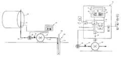
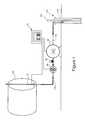
- FIG. 1illustrates a hydrocarbon additive injection system
- FIG. 2illustrates a block diagram of one embodiment of a controller of a hydrocarbon additive injection system.
- FIG. 3illustrates a pump control signal and a pump output volume.
- FIG. 4is a graph of per cycle injection rates versus a target injection rate.
- FIG. 5is a graph of cumulative injection volumes verses a cumulative target injection volume.
- FIG. 6is a process flow sheet of one embodiment of a volumetric control process that may be implemented by an additive injection system controller.
- FIG. 7is a process flow sheet of another embodiment of a volumetric control process that may be implemented by an additive injection system controller.
- FIG. 1is an exemplary diagram of a well site incorporating an additive injection system. As illustrated, the system is operative to inject chemical or additives (hereafter additives) into a wellbore 100 . In other embodiments, it will be appreciated that the injection system may inject additives into other productions systems (e.g., pipelines etc.).
- the wellbore 100may be a production well having any completion equipment and a subterranean production zone (not illustrated), which typically includes multiple perforations through the casing 110 of the well bore 100 . Such perforation allow hydrocarbons (e.g., gas, oil) to enter into the casing.
- Production tubing 120is utilized to remove the hydrocarbons from the wellbore casing.
- smaller diameter production tubing 120is inserted into the casing and is used to carry the fluid from the production zones to the surface.
- Various wellhead equipmentmay be included such as blow-out preventers, valves, storage tanks, pipelines etc (not shown) as is well known in the art and thus are not described in greater detail.
- a fluid additiveis stored in an additive storage tank 130 (e.g., source) and is injected into the wellbore 100 via a suitable pump 60 , such as a positive displacement pump. More specifically, an inlet of the pump 60 is connected to the additive storage tank 130 via a first fluid conduit 132 and an outlet of the pump 60 is connected to the wellbore via a second fluid conduit 134 .
- the pumpis operated by an electric motor.
- the additiveflows through the conduits 132 , 134 and discharges into the well bore casing 110 . In the illustrated embodiment, the additives are discharged in the casing near the surface.
- additivesmay be discharged at a subterranean location near the production zone via appropriate tubing or conduits.
- multiple additive sourcesmay be provided via separate injection lines to allow for injection of different additives. The same also holds for injection of additives in pipelines or surface processing facilities.
- a flow meter 90measures the flow rate through the first fluid conduit 132 provides signals representative of the volume passing through the fluid conduit.
- the flow meter 90generates an output signal indication of a volume of additive passing through the conduit during each injector cycle.
- the flow metermay be reset after each injection cycle to provide an accurate per cycle volume measure.
- a Blancett® Model B 1750 positive displacement flow meteris utilized. This meter typically utilizes a large gear ratio (e.g., 13000:1) to provide high accuracy at low flow rates.
- other flow metersmay be utilized.
- the flow meter 90in the present embodiment, is located in the first fluid conduit 132 upstream of the pump 60 .
- one embodiment of the systemincorporates a pulsation dampener 92 that is disposed between the flow meter 90 and the pump 60 .
- pumpstypically produce pulsating flows. This is especially evident in reciprocating positive displacement pumps.
- the pulsating flows or pressure spikes caused by the pumpcan reverberate though the fluid conduit 132 between the pump 60 and the flow meter 90 . This is true even when the flow meter 90 is disposed upstream of the pump 60 .
- These pressure variationsaffect the accuracy of the flow meter volume measurements. When volumes measured by the flow meter are very small, the effect of the pulsating flows can lead to significant inaccuracies in the volume measurements.
- the pulsation dampenermay be utilized to substantially isolate the flow meter 90 from pressure variations caused by the pump 60 .
- the pulsation dampener 92is an in-line device that dampens pressure variations in the fluid conduit 132 or 134 to prevent their continued propagation.
- the pulsation dampener 92is a gas-filled vessel that absorbs pressure variation caused by the pump by alternately compressing and expanding a gas cushion in synchronization with the motion of the pump.
- the gas cushionis normally an inert gas (e.g., nitrogen) that is separated from the fluid by a flexible membrane (i.e. bladder, diaphragm or bellows).
- Exemplary pulsation dampenersare available from Flowguard USA, of Houston Tex. However, any appropriate flow dampening device may be utilized.
- An onsite injection controller 10controls the operation of the pump 60 , either utilizing programs stored in a memory associated with the controller 10 , instructions entered by a user and/or using instructions provided to the controller 10 from a remote location.
- the injection controller 10controls when the injection pump 60 turns on and off in order to inject a predetermined volume of additive into a subterranean hydrocarbon gas or oil well or associated production and process systems in either a single batch or more commonly in multiple cycles per day (e.g., pump cycles, injection cycles).
- the controller 10uses a stored program containing instructions that control the pump 60 (e.g., activate and deactivate) based on a total volume of additive to be injected over a predetermined or user set time period (e.g.
- the controlleris operative to activate the pump until a desired volume of additive passes through the flow meter 90 at which time the pump 60 is deactivated.
- a volumetric controlthat allows for, among other things, eliminating the need to perform an injection rate test data or otherwise account for well specific and/or pump specific variables. Stated otherwise, the volumetric control allows for injecting a desired volume of additive irrespective of individual wellhead considerations or specific pump operating characteristics.
- FIG. 2shows an overall block diagram of the controller 10 .
- the injection controller 10has a computer 12 , a user interface device 14 , a pump control output module 16 , a system interface device 18 , a power interface module 52 , a power bus 54 and, typically, one or more internal batteries 70 .
- the controller 10may take power from a conventional AC or DC power supply 68 (e.g., utility electric line) that is connected to the power interface module 52 .
- the power interface module 52converts received AC or DC power to a predetermined power configuration.
- the power interface module 52is connected to the power bus 54 to provide the predetermined power to the power bus 54 .
- the power bus 54is connected to the computer 12 , the user interface device 14 , the controller 10 , the pump control output module 16 and the system interface device 18 to supply the predetermined power to these components.
- the power supplymay also be connected to the pump 60 .
- the internal battery 70is also connected to the power interface module 52 to serve as a temporary source of electrical power if other power is not available.
- the controller 10may alternatively take electrical power from a solar panel, wind turbine or other electric generator 62 through a power controller 64 and/or an external storage battery 66 where such an alternate or non-conventional power source is connected to the power interface module 52 either instead of or in addition to conventional power.
- the pump 60may be connected to a non-conventional power source.
- the user interface device 14provides communication between the user and the controller 10 by allowing the user to input the user input data, to input user instructions and to see status data.
- a userinputs information regarding an injection period, total volume to be injected during the injection period and the frequency or number of injections during the injection period.
- a usermay specify an injection period of 1 day for 1 L of additive to be injected in discrete injections once per minute (e.g. 1440 times a day).
- the controller 10uses the user input data to determine a per injection volume (e.g., target volume) required to achieve the specified total volume over the specified injection period.
- a per injection volumee.g., target volume
- the controller 10calculates the target injection volume, the controller is operative to activate and deactivate the pump 60 on the specified injection schedule (e.g., once per minute) to deliver the target injection volume. More specifically, the controller activates the pump until the flow meter 90 indicates that the volume pumped by the pump meets or exceeds the per cycle target volume, at which time the pump is deactivated.
- the pump control output module 16is connected to the pump control system 58 (e.g., relay switch) of the injection pump 60 such that a signal from the pump control output module 16 cooperates with the control system of the injection pump 60 to turn the injection pump on and off.
- the pump control output module 16is connected to the injection pump control system 58 through at least one intrinsically safe electrical barrier 56 .
- connection between the controller 10 and other componentsis made using conduit and conduit fittings with wiring received inside the conduit and conduit fittings that suitable for use in and around the area of a wellhead, which may have a hazardous area classification of a Class I, Group D, Division 1 or 2 location as defined in the National Electric Code, that is often referred to in the petroleum industry as an ‘explosion-proof’ wiring system.
- the controllermay also control the activation and deactivation of a pneumatic pump by controlling a pneumatic actuator.
- the system interface device 18is connected to the computer 12 , to the user interface device 14 , to the pump control output module 16 and the flow meter 90 .
- the system interface device 18receives the user input data and the user instructions from the user interface device 14 and transmits the user input data and the user's instructions to the computer 12 .
- the system interface device 18relays commands from the computer 12 to the pump control output module 16 .
- the system interface devicerelays signals from the flow meter 90 to the computer 12 .
- the flow meter output signalsmay be provided to the computer 12 or the computer may poll the flow meter.
- the computer 12 in the controller 10includes a Central Processor Unit 20 (CPU) and a memory 22 .
- the memory 22may include read only memories (ROM) for storing programs, tables and models, and random access memories (RAM) for storing data.
- ROMread only memories
- RAMrandom access memories
- the memory 22holds a stored program or algorithm where the stored program is used to determine the per cycle target injection volume for the injection pump 60 in order to inject a predetermined amount of a additive into a well over correct number of cycles. Additionally, the memory holds a stored program or algorithm for altering the per cycle injection volume as more fully set forth below.
- the user interface device 14is a local user interface panel 26 .
- the local user interface panel 26further comprises a display 48 and one or more keypads 32 , 36 where the display 48 and the keypads 32 , 36 cooperate to provide local communication between user and said controller 10 such that user can input the user input data into the controller 10 , can input the user instructions into the controller 10 and the controller 10 can show status data.
- the exact configuration of the controller interfacemay be varied.
- the user interface device 14includes an optional communication module 30 and a remote control and status station 28 for remote control of the controller 10 .
- the communication module 30may receives the user input data from and/or transmits status data to the remote control and status station 28 .
- the communication module 30is connected to the system interface device 18 such that the system interface device 18 receives the user input data and user instructions from the communication module 30 , transmits the user input data and user instructions to the computer 12 and transmits the status data to the communication module 30 .
- Communication between the communication module 30 and a remote control and status station 28may be accomplished by standard phone line link 80 , cellular-telephone link or by satellite radio link where the communication module 30 has a modem, a cellular-telephone transceiver or a satellite radio transceiver depending on the link used. Additionally, radio frequency (RF) communications may be utilized.
- RFradio frequency
- the injection controller 10is connected to an optional additive storage tank level transducer 72 where the storage tank level transducer 72 is in fluid communication with the additive inside the additive storage tank such that the additive tank level transducer 72 generates an input in response to the level of the additive in the storage tank.
- the storage tank level transducer 72is connected to the system interface device 18 to provide an input to the computer 12 that indicates that the additive tank is empty so that the computer 12 may deactivate the pump 60 .
- the ability to volumetrically control the injection pump 60 operation based on a measured pumped volumeallows the controller to be incorporated with any pump. Accordingly, the controller 10 may be retrofit to existing pumps. That is, no specialized pump is required. However, it has been recognized that simple volumetric control can lead to certain inefficiencies. For instance, many pumps continue to operate for a short duration after power to the pump is shut off. Stated otherwise, many pumps coast to a stop after power is shut off and continue to pump additive as they coast to a stop. This is especially apparent in pumps that utilize a brushed motor, however, it also is present in pumps utilizing brushless motors, albeit to a lesser extent.
- FIG. 3illustrates continued pumping (i.e., pump coast) after pump shut down.
- a control signal 140 generated by the controller 10is provided to the pump control system 58 .
- Such a signalmay be represented as a square wave where power is either on or off for an operation duration (t).
- power activation line 148the pump has to overcome inertia to begin pumping and ramps up to a steady state operation as illustrated by the upward slope 152 of pump operation curve 150 .
- the inertia of the pumpalso results in continued pump operation, when power is terminated, as shown by the downward slope 154 of curve 150 .
- the area under the pump operation curve 150represents the total volume pumped during operation of the pump.
- the shaded area 156below the pump curve 150 and beyond power deactivation line 158 , graphically represents an excess volume of additive pumped during the pump cycle.
- the excess volume additive pumped during shutdown of the pump motoris of little consequence when additives are injected in a few long pump cycles over a large time period (e.g., four cycles per day). In such instances, the excess volume may represent a small fraction of the total volume.
- injection applications having hundreds or thousands of short injection cyclese.g., 1440 cycles per day; once per minute as per current industry standard in gas well production
- the cumulative effect of the additional volume of additives pumped during shutdown/pump coastcan lead to significant over injection of such additives. It has been found that excess injection resulting from pump coast in applications having hundreds or thousands of injection cycles for low volume injections often results in total injection volumes of 140%-250% of a target injection volume. As will be appreciated, this over injection of additives is wasteful and can lead to significant increased operating expenses especially for large operators who maintain hundreds or thousands of wells.
- a target injection volumei.e., target cycle volume
- a cumulative injection volume of 1 literis 0.1 L to produce a cumulative injection volume of 1 liter:
- Cycle Volume1 2 3 4 5 6 7 8 9 10 Totals Target 0.1 0.1 0.1 0.1 0.1 0.1 0.1 0.1 0.1 0.1 1 Cycle Volume Measured 0.46 0.24 0.24 0.13 0.15 0.15 0.16 0.19 0.17 0.19 2.08 Cycle Volume Cycle ⁇ 0.36 ⁇ 0.14 ⁇ 0.14 ⁇ 0.03 ⁇ 0.05 ⁇ 0.05 ⁇ 0.06 ⁇ 0.09 ⁇ 0.07 ⁇ 0.09 Difference As shown, simple volumetric pump control where pump operation is terminated after pumping a target cycle volume results in significant over injection during each cycle. More specifically, during each pump cycle, the pump is activated and the flow meter reads the volume of the additive entering (or exiting) the pump until the measured flow volume exceeds the target cycle volume.
- the pumpis then disengaged but the flow meter continues to measure the volume of additive that is being injected as the pump slows to a stop.
- the total or actual volumeis evaluated (i.e., measured cycle volume). As shown, the total measured volume injected during the ten injection cycles is over double (i.e., 2.08) the target injection volume due to pump coast.
- PPCPredictive Pump Coast
- PPCmeasures the actual volume pumped during a pump cycle and compares the actual volume to a fixed target volume for the pump cycles. If the actual volume exceeds the fixed target volume for the pump cycle, an adjusted cycle volume is calculated for the subsequent cycle.
- the subsequent pump cyclee.g., second pump cycle
- the subsequent pump cyclemay utilize an adjusted cycle volume of 0.08 L. Accordingly, the actual volume pumped during the subsequent pump cycle may be again compared to the original fixed target volume in order to further adjust the next pump cycle.
- the adjusted cycle volumemay be further reduced to, for example 0.07 L for the next (e.g., third) pump cycle.
- the ability to adjust the cycle volumes for pump cyclesprovides a means for accounting for pump coast during pump shut down. Specifically, during a pump cycle, the pump is activated and the flow meter reads the volume of the chemical or additive entering (or exiting) the pump until the measured flow volume exceeds the fixed target volume on the first pump cycle (or adjusted cycle volume for subsequent cycles).
- the pumpis then disengaged but the flow meter continues to measure the volume of additive that is being injected as the pump slows to a stop. After the flow meter is no longer measuring positive fluid movement, the total or actual volume is evaluated and compared to the fixed target cycle volume such that additional adjustment may be made to the adjusted cycle volume. This iteratively fine tunes the adjusted cycle volume such that upon pumping the adjusted cycle volume and deactivating the pump, the total volume pumped by the pump while active and during pump coast will approach the fixed target cycle volume.
- the fixed target cycle volume for each cycleis 0.1 liters.
- the actual volume pumped (i.e., measured cycle volume) during the first cycleis measured at 0.18 liters.
- the cycle difference between the measured cycle volume (0.18 L) and the fixed target cycle volume (0.1 L)is ⁇ 0.08 liters. That is, an excess of 0.08 liters was pumped during the first pump cycle. This difference is removed from the initial adjusted cycle volume of 0.1 L (which is initially set to the fixed target cycle volume) to produce an adjusted cycle volume of 0.02 liters for the second pump cycle.
- the pumpis activated until the flow meter reads the volume of additive entering (or exiting) the pump meets or exceeds 0.02 liters, at which time the pump is deactivated.
- the volume for the second pump cycleis measured (i.e., measured cycle volume).
- the measured second cycle volumeis 0.16 a difference of ⁇ 0.06 from the fixed target cycle volume of 0.1.
- FIG. 4illustrates the target cycle volumes without PPC 204 , with PPC 206 in comparison to the fixed per cycle target volume 202 .
- the fixed target volume 202remains constant at 0.1 throughout the ten pump cycles.
- Volumetric control without PPC 204results in significant over injection during each of the pump cycles.
- PPC 206results in an iterative over injection and under injection that better approximates the fixed target cycle volume.
- over injectionis significantly reduced.
- FIG. 5which shows a running total volume by cycle.
- the target volume 212increases by a fixed amount (0.1 L) each cycle.
- the running total volume or cumulative volume of the volumetric control without PPC 214increases at a significant rate in excess of the target volume 212 .
- the cumulative volume produced through volumetric pump control with PPC 214closely approximates the target volume.
- FIG. 6illustrates a process 300 that may be implemented by the controller (e.g., as an algorithm or software program). While the aspects described herein are in the general context of computer-executable instructions of computer programs and software that run on computers (e.g., controller, etc.), those skilled in the art will recognize that the process 300 also can be implemented in combination with other program modules, firmware and hardware that perform particular tasks.
- the illustrated process 300is one implementation of the PPC process discussed above. This process 300 may be incorporated into a OEM system having a specified controller, pump and flow meter. However, it will be further appreciated that the process may be implemented in a controller that is utilized with an existing pump and, if available, existing flow meter. Finally, it will be appreciated that the process may be implemented as a set of computer-executable instructions that may be stored or downloaded to an existing controller having appropriate controller inputs and outputs.
- the processbegins with establishing 302 a per cycle fixed target volume.
- establishing such a fixed target volumemay include receiving various user inputs identifying a specified total injection volume over the specified injection period and/or a desired number of injections/pump cycles.
- the fixed target volumeis calculated by dividing the total injection volume by the number of desired injections.
- the processincludes activating and deactivating 304 an injection pump upon receiving a signal from a flow meter indicating a target volume has been pumped or injected. That is, the pump is operated until the pumped volume meets or exceeds the fixed target volume as measured by the flow meter.
- an actual volume pumped during the pump cycleis measured 306 . Measuring the actual volume pumped after cessation of all fluid flow through the fluid conduit allows for measuring excess volume due to pump coast after deactivation of the pump.
- a difference between the actual volume pumped and the fixed target volumeis calculated 308 . Based on this difference, the process includes generating 310 an adjusted cycle volume.
- the adjusted cycle volumemay represent a reduction of the fixed target volume after the first pump cycle by the difference of the actual pumped volume and the fixed target volume. In subsequent pump cycles, a previous adjusted cycle volume may be further adjusted based on the difference.
- the processmay determine 312 if the adjusted cycle volume is less than zero. If so, the pump is not activated during the next pump cycle. Stated otherwise, the pump is deactivated 314 during the next pump cycle.
- the processagain includes activating and deactivating 316 the injection pump upon receiving a signal from the flow meter indicative that the adjusted cycle volume has been pumped. After all fluid flow ceases through a fluid conduit monitored by the flow meter, an actual volume pumped during the pump cycle is measured 318 .
- the processdetermines 320 if there is another pump cycle for the injection period. If the injection period does include another pump cycle 320 the process steps of 308 through 320 are iteratively repeated. After all of the pump cycles are completed for injection period, the process 300 ends.
- PPCallows for adjusting the pumped volume to iteratively estimate an adjusted pump cycle volume to pump in order to achieve a desired fixed target volume
- variationsmay be made to the overall process. For instance, use of the flow meter to measure actual flows after fluid flow through monitored fluid conduit ceases allows for a modified process that, instead of adjusting subsequent pump volumes, skips injections until an actual or measured pumped volume substantially aligns with the target volume.
- Such a modified processmay be implemented in an injection process having multiple (e.g., hundreds or thousands) of injection cycles where periodically skipping in injection cycle is permissible.
- FIG. 7illustrates modified volume control process 400 .
- the process 400includes establishing 402 a per cycle fixed target volume. As above, establishing such a per cycle fixed target volume may include establishing a total injection volume and number of pump cycles for an injection period.
- the processincludes activating and deactivating 404 an injection pump upon receiving a signal from a flow meter indicating that the target volume has been pumped. Once all fluid flow ceases through a fluid conduit monitored by the flow meter, an actual volume pumped during the activation and deactivation of the pump (i.e., pump cycle) may be measured 406 .
- the processincludes calculating 408 a cumulative total measured or actual injection volume after the last completed pump cycle.
- this valuemay be compared to a calculated 410 cumulative target volume for all completed pump cycles (e.g. cumulative pump cycles multiplied by per cycle target volume).
- the process 400determines 412 if the cumulative actual injection volume for all completed cycles exceeds the cumulative target volume for all completed pump by more that one fixed per cycle target volume (i.e., the target volume for next pump cycle). If so, the pump is deactivated 414 during the next pump cycle. While skipping the injection, the pump cycle is considered completed for purposes of calculating the cumulative target volume. Any time the cumulative measured volume is not greater than the cumulative target volume plus one cycle target volume, the process 400 continues 416 until all injection cycles are complete.
Landscapes
- Engineering & Computer Science (AREA)
- Geology (AREA)
- Life Sciences & Earth Sciences (AREA)
- Mining & Mineral Resources (AREA)
- Physics & Mathematics (AREA)
- Environmental & Geological Engineering (AREA)
- Fluid Mechanics (AREA)
- General Life Sciences & Earth Sciences (AREA)
- Geochemistry & Mineralogy (AREA)
- Geophysics (AREA)
- Mechanical Engineering (AREA)
- General Engineering & Computer Science (AREA)
- Control Of Positive-Displacement Pumps (AREA)
Abstract
Description
| TABLE 1 | |||
| Volume | |||
| 1 | 2 | 3 | 4 | 5 | 6 | 7 | 8 | 9 | 10 | Totals | ||
| Target | 0.1 | 0.1 | 0.1 | 0.1 | 0.1 | 0.1 | 0.1 | 0.1 | 0.1 | 0.1 | 1 |
| Cycle | |||||||||||
| Volume | |||||||||||
| Measured | 0.46 | 0.24 | 0.24 | 0.13 | 0.15 | 0.15 | 0.16 | 0.19 | 0.17 | 0.19 | 2.08 |
| Cycle | |||||||||||
| Volume | |||||||||||
| Cycle | −0.36 | −0.14 | −0.14 | −0.03 | −0.05 | −0.05 | −0.06 | −0.09 | −0.07 | −0.09 | |
| Difference | |||||||||||
As shown, simple volumetric pump control where pump operation is terminated after pumping a target cycle volume results in significant over injection during each cycle. More specifically, during each pump cycle, the pump is activated and the flow meter reads the volume of the additive entering (or exiting) the pump until the measured flow volume exceeds the target cycle volume. The pump is then disengaged but the flow meter continues to measure the volume of additive that is being injected as the pump slows to a stop. After the flow meter is no longer measuring positive fluid movement, the total or actual volume is evaluated (i.e., measured cycle volume). As shown, the total measured volume injected during the ten injection cycles is over double (i.e., 2.08) the target injection volume due to pump coast.
| TABLE 2 | |||
| Cycle | Volume | ||
| W/ | 1 | 2 | 3 | 4 | 5 | 6 | 7 | 8 | 9 | 10 | Totals |
| Target | 0.1 | 0.1 | 0.1 | 0.1 | 0.1 | 0.1 | 0.1 | 0.1 | 0.1 | 0.1 | 1 |
| Cycle | |||||||||||
| Volume | |||||||||||
| Adjusted | 0.1 | 0.02 | −0.04 | 0.06 | 0.07 | 0.05 | 0.05 | 0.04 | 0.01 | 0.03 | |
| Cycle | |||||||||||
| Volume | |||||||||||
| Measured | 0.18 | 0.16 | 0 | 0.09 | 0.12 | 0.1 | 0.11 | 0.13 | 0.08 | 0.12 | 1.09 |
| Cycle | |||||||||||
| Volume | |||||||||||
| Cycle | −0.08 | −0.06 | 0.1 | 0.01 | −0.02 | 0 | −0.01 | −0.03 | 0.02 | −0.02 | |
| Difference | |||||||||||
| New | 0.02 | −0.04 | 0.06 | 0.07 | 0.05 | 0.05 | 0.04 | 0.01 | 0.03 | 0.01 | |
| Adjusted | |||||||||||
| Cycle | |||||||||||
| Volume | |||||||||||
As shown, by adjusting the target volume for each cycle, at the end often injection cycles the total volume injected is only 9% greater than the total target volume.
Claims (16)
Priority Applications (3)
| Application Number | Priority Date | Filing Date | Title |
|---|---|---|---|
| US14/185,180US9714741B2 (en) | 2014-02-20 | 2014-02-20 | Method and system to volumetrically control additive pump |
| PCT/US2014/062243WO2015126465A1 (en) | 2014-02-20 | 2014-10-24 | Method and system to volumetrically control additive pump |
| CA2869013ACA2869013C (en) | 2014-02-20 | 2014-10-28 | Method and system to volumetrically control additive pump |
Applications Claiming Priority (1)
| Application Number | Priority Date | Filing Date | Title |
|---|---|---|---|
| US14/185,180US9714741B2 (en) | 2014-02-20 | 2014-02-20 | Method and system to volumetrically control additive pump |
Publications (2)
| Publication Number | Publication Date |
|---|---|
| US20150233530A1 US20150233530A1 (en) | 2015-08-20 |
| US9714741B2true US9714741B2 (en) | 2017-07-25 |
Family
ID=53797751
Family Applications (1)
| Application Number | Title | Priority Date | Filing Date |
|---|---|---|---|
| US14/185,180Expired - Fee RelatedUS9714741B2 (en) | 2014-02-20 | 2014-02-20 | Method and system to volumetrically control additive pump |
Country Status (3)
| Country | Link |
|---|---|
| US (1) | US9714741B2 (en) |
| CA (1) | CA2869013C (en) |
| WO (1) | WO2015126465A1 (en) |
Cited By (2)
| Publication number | Priority date | Publication date | Assignee | Title |
|---|---|---|---|---|
| US20160143228A1 (en)* | 2013-07-05 | 2016-05-26 | Rockwool International A/S | Plant growth system |
| US11035211B1 (en)* | 2020-02-20 | 2021-06-15 | Well-Focused Technologies, LLC | Scalable treatment systems and methods for autonomous chemical treatment |
Families Citing this family (48)
| Publication number | Priority date | Publication date | Assignee | Title |
|---|---|---|---|---|
| US10254732B2 (en) | 2012-11-16 | 2019-04-09 | U.S. Well Services, Inc. | Monitoring and control of proppant storage from a datavan |
| US9745840B2 (en) | 2012-11-16 | 2017-08-29 | Us Well Services Llc | Electric powered pump down |
| US10232332B2 (en) | 2012-11-16 | 2019-03-19 | U.S. Well Services, Inc. | Independent control of auger and hopper assembly in electric blender system |
| US9410410B2 (en) | 2012-11-16 | 2016-08-09 | Us Well Services Llc | System for pumping hydraulic fracturing fluid using electric pumps |
| US9995218B2 (en) | 2012-11-16 | 2018-06-12 | U.S. Well Services, LLC | Turbine chilling for oil field power generation |
| US10407990B2 (en) | 2012-11-16 | 2019-09-10 | U.S. Well Services, LLC | Slide out pump stand for hydraulic fracturing equipment |
| US11476781B2 (en) | 2012-11-16 | 2022-10-18 | U.S. Well Services, LLC | Wireline power supply during electric powered fracturing operations |
| US9970278B2 (en) | 2012-11-16 | 2018-05-15 | U.S. Well Services, LLC | System for centralized monitoring and control of electric powered hydraulic fracturing fleet |
| US10036238B2 (en) | 2012-11-16 | 2018-07-31 | U.S. Well Services, LLC | Cable management of electric powered hydraulic fracturing pump unit |
| US9893500B2 (en) | 2012-11-16 | 2018-02-13 | U.S. Well Services, LLC | Switchgear load sharing for oil field equipment |
| US10020711B2 (en) | 2012-11-16 | 2018-07-10 | U.S. Well Services, LLC | System for fueling electric powered hydraulic fracturing equipment with multiple fuel sources |
| US11449018B2 (en) | 2012-11-16 | 2022-09-20 | U.S. Well Services, LLC | System and method for parallel power and blackout protection for electric powered hydraulic fracturing |
| US11959371B2 (en) | 2012-11-16 | 2024-04-16 | Us Well Services, Llc | Suction and discharge lines for a dual hydraulic fracturing unit |
| CA2908276C (en) | 2014-10-14 | 2022-11-01 | Us Well Services Llc | Parallel power and blackout protection for electric hydraulic fracturing |
| US9856721B2 (en)* | 2015-04-08 | 2018-01-02 | Baker Hughes, A Ge Company, Llc | Apparatus and method for injecting a chemical to facilitate operation of a submersible well pump |
| RU2700358C1 (en) | 2015-10-22 | 2019-09-16 | Статойл Петролеум Ас | Method and system for optimizing the addition of a viscosity reducer to an oil well comprising a downhole pump |
| US12078110B2 (en) | 2015-11-20 | 2024-09-03 | Us Well Services, Llc | System for gas compression on electric hydraulic fracturing fleets |
| CA2987665C (en) | 2016-12-02 | 2021-10-19 | U.S. Well Services, LLC | Constant voltage power distribution system for use with an electric hydraulic fracturing system |
| CN106895263B (en)* | 2017-02-24 | 2019-05-07 | 中国石油天然气集团公司 | A kind of Product oil measuring adjusting method |
| WO2019050722A1 (en)* | 2017-09-11 | 2019-03-14 | Reservoir Metrics Ip Holdings, Llc | Tracer injection with integrated product identification |
| CA3078509A1 (en) | 2017-10-05 | 2019-04-11 | U.S. Well Services, LLC | Instrumented fracturing slurry flow system and method |
| US10408031B2 (en) | 2017-10-13 | 2019-09-10 | U.S. Well Services, LLC | Automated fracturing system and method |
| AR114805A1 (en) | 2017-10-25 | 2020-10-21 | U S Well Services Llc | INTELLIGENT FRACTURING METHOD AND SYSTEM |
| AR113611A1 (en) | 2017-12-05 | 2020-05-20 | U S Well Services Inc | MULTIPLE PLUNGER PUMPS AND ASSOCIATED DRIVE SYSTEMS |
| WO2019113153A1 (en) | 2017-12-05 | 2019-06-13 | U.S. Well Services, Inc. | High horsepower pumping configuration for an electric hydraulic fracturing system |
| CA3090408A1 (en) | 2018-02-05 | 2019-08-08 | U.S. Well Services, LLC | Microgrid electrical load management |
| AR115054A1 (en) | 2018-04-16 | 2020-11-25 | U S Well Services Inc | HYBRID HYDRAULIC FRACTURING FLEET |
| CA3103490A1 (en) | 2018-06-15 | 2019-12-19 | U.S. Well Services, LLC | Integrated mobile power unit for hydraulic fracturing |
| US10648270B2 (en) | 2018-09-14 | 2020-05-12 | U.S. Well Services, LLC | Riser assist for wellsites |
| CA3115669A1 (en) | 2018-10-09 | 2020-04-16 | U.S. Well Services, LLC | Modular switchgear system and power distribution for electric oilfield equipment |
| WO2020081313A1 (en) | 2018-10-09 | 2020-04-23 | U.S. Well Services, LLC | Electric powered hydraulic fracturing pump system with single electric powered multi-plunger pump fracturing trailers, filtration units, and slide out platform |
| US11578577B2 (en) | 2019-03-20 | 2023-02-14 | U.S. Well Services, LLC | Oversized switchgear trailer for electric hydraulic fracturing |
| US11728709B2 (en) | 2019-05-13 | 2023-08-15 | U.S. Well Services, LLC | Encoderless vector control for VFD in hydraulic fracturing applications |
| AR119134A1 (en) | 2019-06-10 | 2021-11-24 | U S Well Services Llc | INTEGRATED COMBUSTION GAS HEATER FOR MOBILE FUEL CONDITIONING EQUIPMENT |
| WO2020251578A1 (en)* | 2019-06-13 | 2020-12-17 | Halliburton Energy Services, Inc. | Multi-component downhole treatment |
| WO2021022048A1 (en) | 2019-08-01 | 2021-02-04 | U.S. Well Services, LLC | High capacity power storage system for electric hydraulic fracturing |
| US11459863B2 (en) | 2019-10-03 | 2022-10-04 | U.S. Well Services, LLC | Electric powered hydraulic fracturing pump system with single electric powered multi-plunger fracturing pump |
| US12012952B2 (en) | 2019-11-18 | 2024-06-18 | U.S. Well Services, LLC | Electrically actuated valves for manifold trailers or skids |
| US11009162B1 (en) | 2019-12-27 | 2021-05-18 | U.S. Well Services, LLC | System and method for integrated flow supply line |
| US11846167B2 (en) | 2019-12-30 | 2023-12-19 | U.S. Well Services, LLC | Blender tub overflow catch |
| US11885206B2 (en) | 2019-12-30 | 2024-01-30 | U.S. Well Services, LLC | Electric motor driven transportation mechanisms for fracturing blenders |
| US11492886B2 (en)* | 2019-12-31 | 2022-11-08 | U.S. Wells Services, LLC | Self-regulating FRAC pump suction stabilizer/dampener |
| US11560887B2 (en) | 2019-12-31 | 2023-01-24 | U.S. Well Services, LLC | Segmented fluid end plunger pump |
| US11960305B2 (en) | 2019-12-31 | 2024-04-16 | U.S. Well Services, LLC | Automated blender bucket testing and calibration |
| US20210206672A1 (en)* | 2020-01-03 | 2021-07-08 | Ugsi Solutions, Inc. | Systems and Methods for Controlling the Feed Rate of Chemicals into a Body of Water |
| US20210372234A1 (en)* | 2020-05-29 | 2021-12-02 | Itt Manufacturing Enterprises Llc | Explosive environment termination of wellhead cables |
| US12404749B2 (en)* | 2021-03-29 | 2025-09-02 | AES SEDAI Technology, LLC | Wellsite greenhouse gas reduction and hydrogen production system and method |
| US11466546B1 (en)* | 2021-03-29 | 2022-10-11 | AES SEDAI Technology, LLC | Wellsite greenhouse gas reduction and hydrogen production system and method |
Citations (66)
| Publication number | Priority date | Publication date | Assignee | Title |
|---|---|---|---|---|
| US3211225A (en) | 1963-05-28 | 1965-10-12 | Signal Oil & Gas Co | Well treating apparatus |
| US3710867A (en) | 1971-01-05 | 1973-01-16 | Petrolite Corp | Apparatus and process for adding chemicals |
| US4064936A (en) | 1976-07-09 | 1977-12-27 | Mcclure L C | Chemical treating system for oil wells |
| US4160734A (en) | 1976-07-26 | 1979-07-10 | Lrs Research Limited | Catch basin processing apparatus |
| US4284143A (en) | 1978-03-28 | 1981-08-18 | Societe Europeenne De Propulsion | System for the remote control, the maintenance or the fluid injection for a submerged satellite well head |
| US4354553A (en) | 1980-10-14 | 1982-10-19 | Hensley Clifford J | Corrosion control downhole in a borehole |
| US4375833A (en) | 1981-09-04 | 1983-03-08 | Meadows Floyd G | Automatic well treatment system |
| US4436148A (en) | 1981-04-27 | 1984-03-13 | Richard Maxwell | Chemical treatment for oil wells |
| US4566536A (en) | 1983-11-21 | 1986-01-28 | Mobil Oil Corporation | Method for operating an injection well in an in-situ combustion oil recovery using oxygen |
| US4580952A (en) | 1984-06-07 | 1986-04-08 | Eberle William J | Apparatus for lifting liquids from subsurface reservoirs |
| US4582131A (en) | 1984-09-26 | 1986-04-15 | Hughes Tool Company | Submersible chemical injection pump |
| JPS61261514A (en) | 1985-05-13 | 1986-11-19 | Showa Tansan Kk | Chemical grout injector |
| US4635723A (en) | 1983-07-07 | 1987-01-13 | Spivey Melvin F | Continuous injection of corrosion-inhibiting liquids |
| US4665981A (en) | 1985-03-05 | 1987-05-19 | Asadollah Hayatdavoudi | Method and apparatus for inhibiting corrosion of well tubing |
| US4721158A (en) | 1986-08-15 | 1988-01-26 | Amoco Corporation | Fluid injection control system |
| US4747451A (en) | 1987-08-06 | 1988-05-31 | Oil Well Automation, Inc. | Level sensor |
| US4830112A (en) | 1987-12-14 | 1989-05-16 | Erickson Don J | Method and apparatus for treating wellbores |
| US4832121A (en) | 1987-10-01 | 1989-05-23 | The Trustees Of Columbia University In The City Of New York | Methods for monitoring temperature-vs-depth characteristics in a borehole during and after hydraulic fracture treatments |
| US4843247A (en) | 1985-11-08 | 1989-06-27 | Cosmo Oil Co., Ltd. | Determination of asphaltene content and device therefor |
| US4901563A (en) | 1988-09-13 | 1990-02-20 | Atlantic Richfield Company | System for monitoring fluids during well stimulation processes |
| US4907857A (en) | 1988-07-25 | 1990-03-13 | Abbott Laboratories | Optical fiber distribution system for an optical fiber sensor |
| US4974929A (en) | 1987-09-22 | 1990-12-04 | Baxter International, Inc. | Fiber optical probe connector for physiologic measurement devices |
| US5059790A (en) | 1990-03-30 | 1991-10-22 | Fiberchem, Inc. | Reservoir fiber optic chemical sensors |
| US5098659A (en) | 1990-09-24 | 1992-03-24 | Abbott Laboratories | Apparatus for continuously monitoring a plurality of chemical analytes through a single optical fiber and method of making |
| US5115811A (en) | 1990-04-30 | 1992-05-26 | Medtronic, Inc. | Temperature measurement and compensation in a fiber-optic sensor |
| US5147561A (en) | 1989-07-24 | 1992-09-15 | Burge Scott R | Device for sampling and stripping volatile chemicals within wells |
| US5172717A (en) | 1989-12-27 | 1992-12-22 | Otis Engineering Corporation | Well control system |
| US5209300A (en) | 1992-02-04 | 1993-05-11 | Ayres Robert N | Pressure regulated chemical injection system |
| US5209301A (en) | 1992-02-04 | 1993-05-11 | Ayres Robert N | Multiple phase chemical injection system |
| US5307146A (en) | 1991-09-18 | 1994-04-26 | Iowa State University Research Foundation, Inc. | Dual-wavelength photometer and fiber optic sensor probe |
| US5353237A (en) | 1992-06-25 | 1994-10-04 | Oryx Energy Company | System for increasing efficiency of chemical treatment |
| US5359681A (en) | 1993-01-11 | 1994-10-25 | University Of Washington | Fiber optic sensor and methods and apparatus relating thereto |
| US5413175A (en) | 1993-05-26 | 1995-05-09 | Alberta Oil Sands Technology And Research Authority | Stabilization and control of hot two phase flow in a well |
| US5418614A (en) | 1991-09-19 | 1995-05-23 | Texaco Inc. | Optical photometry system for on-line analysis of fluid systems |
| US5517593A (en) | 1990-10-01 | 1996-05-14 | John Nenniger | Control system for well stimulation apparatus with response time temperature rise used in determining heater control temperature setpoint |
| US5570437A (en) | 1993-11-26 | 1996-10-29 | Sensor Dynamics, Ltd. | Apparatus for the remote measurement of physical parameters |
| US5569838A (en) | 1994-03-05 | 1996-10-29 | Testo Gmbh & Co. | Process and device for measuring a gas medium with a chemical sensor |
| US5590958A (en) | 1989-08-02 | 1997-01-07 | Steward & Stevenson Services, Inc. | Automatic cementing system for precisely obtaining a desired cement density |
| US5672515A (en) | 1995-09-12 | 1997-09-30 | Optical Sensors Incorporated | Simultaneous dual excitation/single emission fluorescent sensing method for PH and pCO2 |
| US5706896A (en) | 1995-02-09 | 1998-01-13 | Baker Hughes Incorporated | Method and apparatus for the remote control and monitoring of production wells |
| US5714121A (en) | 1995-09-28 | 1998-02-03 | Optical Sensors Incorporated | Optical carbon dioxide sensor, and associated methods of manufacture |
| US5735346A (en) | 1996-04-29 | 1998-04-07 | Itt Fluid Technology Corporation | Fluid level sensing for artificial lift control systems |
| US5747348A (en) | 1995-07-05 | 1998-05-05 | The Aerospace Corporation | Diode laser interrogated fiber optic hydrazine-fuel sensor |
| US5829520A (en) | 1995-02-14 | 1998-11-03 | Baker Hughes Incorporated | Method and apparatus for testing, completion and/or maintaining wellbores using a sensor device |
| WO1998050680A2 (en) | 1997-05-02 | 1998-11-12 | Baker Hughes Incorporated | Monitoring of downhole parameters and tools utilizing fiber optics |
| WO1998057030A1 (en) | 1997-06-09 | 1998-12-17 | Baker Hughes Incorporated | Control and monitoring system for chemical treatment of an oilfield well |
| US5872876A (en) | 1996-02-16 | 1999-02-16 | Sensor Dynamics Limited | Optical fibre sensor element |
| US5937946A (en) | 1998-04-08 | 1999-08-17 | Streetman; Foy | Apparatus and method for enhancing fluid and gas flow in a well |
| US5992250A (en) | 1996-03-29 | 1999-11-30 | Geosensor Corp. | Apparatus for the remote measurement of physical parameters |
| US5992230A (en) | 1997-11-15 | 1999-11-30 | Hoffer Flow Controls, Inc. | Dual rotor flow meter |
| US6006828A (en) | 1994-09-16 | 1999-12-28 | Sensor Dynamics Limited | Apparatus for the remote deployment of valves |
| US6006832A (en) | 1995-02-09 | 1999-12-28 | Baker Hughes Incorporated | Method and system for monitoring and controlling production and injection wells having permanent downhole formation evaluation sensors |
| US6022748A (en) | 1997-08-29 | 2000-02-08 | Sandia Corporation - New Mexico Regents Of The University Of California | Sol-gel matrices for direct colorimetric detection of analytes |
| US6026847A (en) | 1995-10-11 | 2000-02-22 | Reinicke; Robert H. | Magnetostrictively actuated valve |
| US6125938A (en) | 1997-08-08 | 2000-10-03 | Halliburton Energy Services, Inc. | Control module system for subterranean well |
| US20030056695A1 (en)* | 2001-09-25 | 2003-03-27 | W.R. Grace & Co.-Conn. | Pumpably verifiable fluid fiber compositions |
| US6851444B1 (en) | 1998-12-21 | 2005-02-08 | Baker Hughes Incorporated | Closed loop additive injection and monitoring system for oilfield operations |
| US20060047360A1 (en)* | 2004-08-24 | 2006-03-02 | Burns Patrick J Sr | Control system and method for chemical injection |
| US20080121391A1 (en) | 2006-10-26 | 2008-05-29 | Multi-Chem Group, Llc | Methods and systems for gas well deliquification |
| US7389787B2 (en) | 1998-12-21 | 2008-06-24 | Baker Hughes Incorporated | Closed loop additive injection and monitoring system for oilfield operations |
| US20090276100A1 (en) | 2008-05-03 | 2009-11-05 | Sauid Arabian Oil Company | System, program product, and related methods for performing automated real-time reservoir pressure estimation enabling optimized injection and production strategies |
| US7841394B2 (en) | 2005-12-01 | 2010-11-30 | Halliburton Energy Services Inc. | Method and apparatus for centralized well treatment |
| US20110186302A1 (en)* | 2009-12-23 | 2011-08-04 | Bp Corporation North America Inc. | Rigless low volume pump system |
| US20120271527A1 (en)* | 2011-04-20 | 2012-10-25 | Hamilton Sundstrand Corporation | Distributed aircraft engine fuel system |
| US8327875B2 (en) | 2007-02-01 | 2012-12-11 | Cameron International Corporation | Chemical-injection management system |
| US8555914B2 (en) | 2007-11-02 | 2013-10-15 | National Coupling Company, Inc. | Method for autonomous control of a chemical injection systems for oil and gas wells |
- 2014
- 2014-02-20USUS14/185,180patent/US9714741B2/ennot_activeExpired - Fee Related
- 2014-10-24WOPCT/US2014/062243patent/WO2015126465A1/enactiveApplication Filing
- 2014-10-28CACA2869013Apatent/CA2869013C/enactiveActive
Patent Citations (67)
| Publication number | Priority date | Publication date | Assignee | Title |
|---|---|---|---|---|
| US3211225A (en) | 1963-05-28 | 1965-10-12 | Signal Oil & Gas Co | Well treating apparatus |
| US3710867A (en) | 1971-01-05 | 1973-01-16 | Petrolite Corp | Apparatus and process for adding chemicals |
| US4064936A (en) | 1976-07-09 | 1977-12-27 | Mcclure L C | Chemical treating system for oil wells |
| US4160734A (en) | 1976-07-26 | 1979-07-10 | Lrs Research Limited | Catch basin processing apparatus |
| US4284143A (en) | 1978-03-28 | 1981-08-18 | Societe Europeenne De Propulsion | System for the remote control, the maintenance or the fluid injection for a submerged satellite well head |
| US4354553A (en) | 1980-10-14 | 1982-10-19 | Hensley Clifford J | Corrosion control downhole in a borehole |
| US4436148A (en) | 1981-04-27 | 1984-03-13 | Richard Maxwell | Chemical treatment for oil wells |
| US4375833A (en) | 1981-09-04 | 1983-03-08 | Meadows Floyd G | Automatic well treatment system |
| US4635723A (en) | 1983-07-07 | 1987-01-13 | Spivey Melvin F | Continuous injection of corrosion-inhibiting liquids |
| US4566536A (en) | 1983-11-21 | 1986-01-28 | Mobil Oil Corporation | Method for operating an injection well in an in-situ combustion oil recovery using oxygen |
| US4580952A (en) | 1984-06-07 | 1986-04-08 | Eberle William J | Apparatus for lifting liquids from subsurface reservoirs |
| US4582131A (en) | 1984-09-26 | 1986-04-15 | Hughes Tool Company | Submersible chemical injection pump |
| US4665981A (en) | 1985-03-05 | 1987-05-19 | Asadollah Hayatdavoudi | Method and apparatus for inhibiting corrosion of well tubing |
| JPS61261514A (en) | 1985-05-13 | 1986-11-19 | Showa Tansan Kk | Chemical grout injector |
| US4843247A (en) | 1985-11-08 | 1989-06-27 | Cosmo Oil Co., Ltd. | Determination of asphaltene content and device therefor |
| US4721158A (en) | 1986-08-15 | 1988-01-26 | Amoco Corporation | Fluid injection control system |
| US4747451A (en) | 1987-08-06 | 1988-05-31 | Oil Well Automation, Inc. | Level sensor |
| US4974929A (en) | 1987-09-22 | 1990-12-04 | Baxter International, Inc. | Fiber optical probe connector for physiologic measurement devices |
| US4832121A (en) | 1987-10-01 | 1989-05-23 | The Trustees Of Columbia University In The City Of New York | Methods for monitoring temperature-vs-depth characteristics in a borehole during and after hydraulic fracture treatments |
| US4830112A (en) | 1987-12-14 | 1989-05-16 | Erickson Don J | Method and apparatus for treating wellbores |
| US4907857A (en) | 1988-07-25 | 1990-03-13 | Abbott Laboratories | Optical fiber distribution system for an optical fiber sensor |
| US4901563A (en) | 1988-09-13 | 1990-02-20 | Atlantic Richfield Company | System for monitoring fluids during well stimulation processes |
| US5147561A (en) | 1989-07-24 | 1992-09-15 | Burge Scott R | Device for sampling and stripping volatile chemicals within wells |
| US5590958A (en) | 1989-08-02 | 1997-01-07 | Steward & Stevenson Services, Inc. | Automatic cementing system for precisely obtaining a desired cement density |
| US5172717A (en) | 1989-12-27 | 1992-12-22 | Otis Engineering Corporation | Well control system |
| US5059790A (en) | 1990-03-30 | 1991-10-22 | Fiberchem, Inc. | Reservoir fiber optic chemical sensors |
| US5115811A (en) | 1990-04-30 | 1992-05-26 | Medtronic, Inc. | Temperature measurement and compensation in a fiber-optic sensor |
| US5098659A (en) | 1990-09-24 | 1992-03-24 | Abbott Laboratories | Apparatus for continuously monitoring a plurality of chemical analytes through a single optical fiber and method of making |
| US5517593A (en) | 1990-10-01 | 1996-05-14 | John Nenniger | Control system for well stimulation apparatus with response time temperature rise used in determining heater control temperature setpoint |
| US5307146A (en) | 1991-09-18 | 1994-04-26 | Iowa State University Research Foundation, Inc. | Dual-wavelength photometer and fiber optic sensor probe |
| US5418614A (en) | 1991-09-19 | 1995-05-23 | Texaco Inc. | Optical photometry system for on-line analysis of fluid systems |
| US5209301A (en) | 1992-02-04 | 1993-05-11 | Ayres Robert N | Multiple phase chemical injection system |
| US5209300A (en) | 1992-02-04 | 1993-05-11 | Ayres Robert N | Pressure regulated chemical injection system |
| US5353237A (en) | 1992-06-25 | 1994-10-04 | Oryx Energy Company | System for increasing efficiency of chemical treatment |
| US5359681A (en) | 1993-01-11 | 1994-10-25 | University Of Washington | Fiber optic sensor and methods and apparatus relating thereto |
| US5413175A (en) | 1993-05-26 | 1995-05-09 | Alberta Oil Sands Technology And Research Authority | Stabilization and control of hot two phase flow in a well |
| US5570437A (en) | 1993-11-26 | 1996-10-29 | Sensor Dynamics, Ltd. | Apparatus for the remote measurement of physical parameters |
| US5569838A (en) | 1994-03-05 | 1996-10-29 | Testo Gmbh & Co. | Process and device for measuring a gas medium with a chemical sensor |
| US6006828A (en) | 1994-09-16 | 1999-12-28 | Sensor Dynamics Limited | Apparatus for the remote deployment of valves |
| US6006832A (en) | 1995-02-09 | 1999-12-28 | Baker Hughes Incorporated | Method and system for monitoring and controlling production and injection wells having permanent downhole formation evaluation sensors |
| US5706896A (en) | 1995-02-09 | 1998-01-13 | Baker Hughes Incorporated | Method and apparatus for the remote control and monitoring of production wells |
| US5829520A (en) | 1995-02-14 | 1998-11-03 | Baker Hughes Incorporated | Method and apparatus for testing, completion and/or maintaining wellbores using a sensor device |
| US5747348A (en) | 1995-07-05 | 1998-05-05 | The Aerospace Corporation | Diode laser interrogated fiber optic hydrazine-fuel sensor |
| US5672515A (en) | 1995-09-12 | 1997-09-30 | Optical Sensors Incorporated | Simultaneous dual excitation/single emission fluorescent sensing method for PH and pCO2 |
| US5714121A (en) | 1995-09-28 | 1998-02-03 | Optical Sensors Incorporated | Optical carbon dioxide sensor, and associated methods of manufacture |
| US6026847A (en) | 1995-10-11 | 2000-02-22 | Reinicke; Robert H. | Magnetostrictively actuated valve |
| US5872876A (en) | 1996-02-16 | 1999-02-16 | Sensor Dynamics Limited | Optical fibre sensor element |
| US5992250A (en) | 1996-03-29 | 1999-11-30 | Geosensor Corp. | Apparatus for the remote measurement of physical parameters |
| US5735346A (en) | 1996-04-29 | 1998-04-07 | Itt Fluid Technology Corporation | Fluid level sensing for artificial lift control systems |
| WO1998050680A2 (en) | 1997-05-02 | 1998-11-12 | Baker Hughes Incorporated | Monitoring of downhole parameters and tools utilizing fiber optics |
| WO1998057030A1 (en) | 1997-06-09 | 1998-12-17 | Baker Hughes Incorporated | Control and monitoring system for chemical treatment of an oilfield well |
| US6125938A (en) | 1997-08-08 | 2000-10-03 | Halliburton Energy Services, Inc. | Control module system for subterranean well |
| US6022748A (en) | 1997-08-29 | 2000-02-08 | Sandia Corporation - New Mexico Regents Of The University Of California | Sol-gel matrices for direct colorimetric detection of analytes |
| US5992230A (en) | 1997-11-15 | 1999-11-30 | Hoffer Flow Controls, Inc. | Dual rotor flow meter |
| US5937946A (en) | 1998-04-08 | 1999-08-17 | Streetman; Foy | Apparatus and method for enhancing fluid and gas flow in a well |
| US6851444B1 (en) | 1998-12-21 | 2005-02-08 | Baker Hughes Incorporated | Closed loop additive injection and monitoring system for oilfield operations |
| US7389787B2 (en) | 1998-12-21 | 2008-06-24 | Baker Hughes Incorporated | Closed loop additive injection and monitoring system for oilfield operations |
| US20030056695A1 (en)* | 2001-09-25 | 2003-03-27 | W.R. Grace & Co.-Conn. | Pumpably verifiable fluid fiber compositions |
| US7277778B2 (en) | 2004-08-24 | 2007-10-02 | Burns Control Company | Control system and method for chemical injection |
| US20060047360A1 (en)* | 2004-08-24 | 2006-03-02 | Burns Patrick J Sr | Control system and method for chemical injection |
| US7841394B2 (en) | 2005-12-01 | 2010-11-30 | Halliburton Energy Services Inc. | Method and apparatus for centralized well treatment |
| US20080121391A1 (en) | 2006-10-26 | 2008-05-29 | Multi-Chem Group, Llc | Methods and systems for gas well deliquification |
| US8327875B2 (en) | 2007-02-01 | 2012-12-11 | Cameron International Corporation | Chemical-injection management system |
| US8555914B2 (en) | 2007-11-02 | 2013-10-15 | National Coupling Company, Inc. | Method for autonomous control of a chemical injection systems for oil and gas wells |
| US20090276100A1 (en) | 2008-05-03 | 2009-11-05 | Sauid Arabian Oil Company | System, program product, and related methods for performing automated real-time reservoir pressure estimation enabling optimized injection and production strategies |
| US20110186302A1 (en)* | 2009-12-23 | 2011-08-04 | Bp Corporation North America Inc. | Rigless low volume pump system |
| US20120271527A1 (en)* | 2011-04-20 | 2012-10-25 | Hamilton Sundstrand Corporation | Distributed aircraft engine fuel system |
Cited By (3)
| Publication number | Priority date | Publication date | Assignee | Title |
|---|---|---|---|---|
| US20160143228A1 (en)* | 2013-07-05 | 2016-05-26 | Rockwool International A/S | Plant growth system |
| US11026372B2 (en)* | 2013-07-05 | 2021-06-08 | Rockwool International A/S | Plant growth system |
| US11035211B1 (en)* | 2020-02-20 | 2021-06-15 | Well-Focused Technologies, LLC | Scalable treatment systems and methods for autonomous chemical treatment |
Also Published As
| Publication number | Publication date |
|---|---|
| CA2869013A1 (en) | 2015-08-20 |
| WO2015126465A1 (en) | 2015-08-27 |
| US20150233530A1 (en) | 2015-08-20 |
| CA2869013C (en) | 2017-05-23 |
Similar Documents
| Publication | Publication Date | Title |
|---|---|---|
| US9714741B2 (en) | Method and system to volumetrically control additive pump | |
| US11939974B2 (en) | Systems and methods of utilization of a hydraulic fracturing unit profile to operate hydraulic fracturing units | |
| US12326075B2 (en) | Stage profiles for operations of hydraulic systems and associated methods | |
| US11692422B2 (en) | System to monitor cavitation or pulsation events during a hydraulic fracturing operation | |
| US20190112910A1 (en) | Automated fracturing system and method | |
| CA2927234C (en) | Well testing and monitoring | |
| US10677041B2 (en) | Fault detection in electric submersible pumps | |
| US8543245B2 (en) | Systems and methods for specifying an operational parameter for a pumping system | |
| US12209489B2 (en) | Instrumented fracturing slurry flow system and method | |
| US10352149B2 (en) | Methods and apparatus to determine production of downhole pumps | |
| RU2482265C2 (en) | Setup method of oil well cluster, and device for oil collection and transport of oil well cluster | |
| WO2016043866A1 (en) | Centrifugal pump degradation monitoring without flow rate measurement | |
| US20180371884A1 (en) | Method for producing from gas slugging reservoirs | |
| Moffett et al. | Real Gas Lift Optimization: An Alternative to Timer Based Intermittent Gas Lift |
Legal Events
| Date | Code | Title | Description |
|---|---|---|---|
| AS | Assignment | Owner name:PCS FERGUSON, INC., COLORADO Free format text:ASSIGNMENT OF ASSIGNORS INTEREST;ASSIGNOR:SANDIDGE, DUSTIN LEVI;REEL/FRAME:032476/0014 Effective date:20140314 | |
| STCF | Information on status: patent grant | Free format text:PATENTED CASE | |
| AS | Assignment | Owner name:JPMORGAN CHASE BANK, N.A., NEW YORK Free format text:SECURITY AGREEMENT;ASSIGNORS:APERGY (DELAWARE) FORMATION, INC.;APERGY BMCS ACQUISITION CORP.;APERGY ENERGY AUTOMATION, LLC;AND OTHERS;REEL/FRAME:046117/0015 Effective date:20180509 | |
| AS | Assignment | Owner name:BANK OF AMERICA, N.A., NORTH CAROLINA Free format text:SECURITY INTEREST;ASSIGNORS:ACE DOWNHOLE, LLC;APERGY BMCS ACQUISITION CORP.;HARBISON-FISCHER, INC.;AND OTHERS;REEL/FRAME:053790/0001 Effective date:20200603 | |
| MAFP | Maintenance fee payment | Free format text:PAYMENT OF MAINTENANCE FEE, 4TH YEAR, LARGE ENTITY (ORIGINAL EVENT CODE: M1551); ENTITY STATUS OF PATENT OWNER: LARGE ENTITY Year of fee payment:4 | |
| AS | Assignment | Owner name:WINDROCK, INC., TEXAS Free format text:RELEASE BY SECURED PARTY;ASSIGNOR:BANK OF AMERICA, N.A.;REEL/FRAME:060305/0001 Effective date:20220607 Owner name:US SYNTHETIC CORPORATION, TEXAS Free format text:RELEASE BY SECURED PARTY;ASSIGNOR:BANK OF AMERICA, N.A.;REEL/FRAME:060305/0001 Effective date:20220607 Owner name:NORRISEAL-WELLMARK, INC., TEXAS Free format text:RELEASE BY SECURED PARTY;ASSIGNOR:BANK OF AMERICA, N.A.;REEL/FRAME:060305/0001 Effective date:20220607 Owner name:APERGY BMCS ACQUISITION CORP., TEXAS Free format text:RELEASE BY SECURED PARTY;ASSIGNOR:BANK OF AMERICA, N.A.;REEL/FRAME:060305/0001 Effective date:20220607 Owner name:THETA OILFIELD SERVICES, INC., TEXAS Free format text:RELEASE BY SECURED PARTY;ASSIGNOR:BANK OF AMERICA, N.A.;REEL/FRAME:060305/0001 Effective date:20220607 Owner name:SPIRIT GLOBAL ENERGY SOLUTIONS, INC., TEXAS Free format text:RELEASE BY SECURED PARTY;ASSIGNOR:BANK OF AMERICA, N.A.;REEL/FRAME:060305/0001 Effective date:20220607 Owner name:QUARTZDYNE, INC., TEXAS Free format text:RELEASE BY SECURED PARTY;ASSIGNOR:BANK OF AMERICA, N.A.;REEL/FRAME:060305/0001 Effective date:20220607 Owner name:PCS FERGUSON, INC., TEXAS Free format text:RELEASE BY SECURED PARTY;ASSIGNOR:BANK OF AMERICA, N.A.;REEL/FRAME:060305/0001 Effective date:20220607 Owner name:NORRIS RODS, INC., TEXAS Free format text:RELEASE BY SECURED PARTY;ASSIGNOR:BANK OF AMERICA, N.A.;REEL/FRAME:060305/0001 Effective date:20220607 Owner name:HARBISON-FISCHER, INC., TEXAS Free format text:RELEASE BY SECURED PARTY;ASSIGNOR:BANK OF AMERICA, N.A.;REEL/FRAME:060305/0001 Effective date:20220607 Owner name:ACE DOWNHOLE, LLC, TEXAS Free format text:RELEASE BY SECURED PARTY;ASSIGNOR:BANK OF AMERICA, N.A.;REEL/FRAME:060305/0001 Effective date:20220607 | |
| AS | Assignment | Owner name:CHAMPIONX LLC, TEXAS Free format text:MERGER;ASSIGNOR:PCS FERGUSON, INC.;REEL/FRAME:065925/0893 Effective date:20231101 | |
| FEPP | Fee payment procedure | Free format text:MAINTENANCE FEE REMINDER MAILED (ORIGINAL EVENT CODE: REM.); ENTITY STATUS OF PATENT OWNER: LARGE ENTITY | |
| AS | Assignment | Owner name:CHAMPIONX LLC, TEXAS Free format text:RELEASE OF SECURITY INTEREST IN PATENTS;ASSIGNOR:JPMORGAN CHASE BANK, N.A.;REEL/FRAME:072004/0019 Effective date:20250716 Owner name:APERGY ESP SYSTEMS, LLC, TEXAS Free format text:RELEASE OF SECURITY INTEREST IN PATENTS;ASSIGNOR:JPMORGAN CHASE BANK, N.A.;REEL/FRAME:072004/0019 Effective date:20250716 Owner name:APERGY BMCS ACQUISITION CORP, TEXAS Free format text:RELEASE OF SECURITY INTEREST IN PATENTS;ASSIGNOR:JPMORGAN CHASE BANK, N.A.;REEL/FRAME:072004/0019 Effective date:20250716 Owner name:HARBISON-FISCHER, INC., TEXAS Free format text:RELEASE OF SECURITY INTEREST IN PATENTS;ASSIGNOR:JPMORGAN CHASE BANK, N.A.;REEL/FRAME:072004/0019 Effective date:20250716 Owner name:NORRIS RODS, INC.,, TEXAS Free format text:RELEASE OF SECURITY INTEREST IN PATENTS;ASSIGNOR:JPMORGAN CHASE BANK, N.A.;REEL/FRAME:072004/0019 Effective date:20250716 Owner name:NORRISEAL-WELLMARK, INC., TEXAS Free format text:RELEASE OF SECURITY INTEREST IN PATENTS;ASSIGNOR:JPMORGAN CHASE BANK, N.A.;REEL/FRAME:072004/0019 Effective date:20250716 Owner name:PCS FERGUSON, INC., TEXAS Free format text:RELEASE OF SECURITY INTEREST IN PATENTS;ASSIGNOR:JPMORGAN CHASE BANK, N.A.;REEL/FRAME:072004/0019 Effective date:20250716 Owner name:QUARTZDYNE, INC., TEXAS Free format text:RELEASE OF SECURITY INTEREST IN PATENTS;ASSIGNOR:JPMORGAN CHASE BANK, N.A.;REEL/FRAME:072004/0019 Effective date:20250716 Owner name:US SYNTHETIC CORPORATION, TEXAS Free format text:RELEASE OF SECURITY INTEREST IN PATENTS;ASSIGNOR:JPMORGAN CHASE BANK, N.A.;REEL/FRAME:072004/0019 Effective date:20250716 | |
| LAPS | Lapse for failure to pay maintenance fees | Free format text:PATENT EXPIRED FOR FAILURE TO PAY MAINTENANCE FEES (ORIGINAL EVENT CODE: EXP.); ENTITY STATUS OF PATENT OWNER: LARGE ENTITY | |
| STCH | Information on status: patent discontinuation | Free format text:PATENT EXPIRED DUE TO NONPAYMENT OF MAINTENANCE FEES UNDER 37 CFR 1.362 | |
| FP | Lapsed due to failure to pay maintenance fee | Effective date:20250725 |