US9714714B2 - Nozzle tip with slit valve for fluid dispenser - Google Patents
Nozzle tip with slit valve for fluid dispenserDownload PDFInfo
- Publication number
- US9714714B2 US9714714B2US14/987,941US201614987941AUS9714714B2US 9714714 B2US9714714 B2US 9714714B2US 201614987941 AUS201614987941 AUS 201614987941AUS 9714714 B2US9714714 B2US 9714714B2
- Authority
- US
- United States
- Prior art keywords
- outlet
- valve
- pump
- nipple
- head portion
- Prior art date
- Legal status (The legal status is an assumption and is not a legal conclusion. Google has not performed a legal analysis and makes no representation as to the accuracy of the status listed.)
- Expired - Fee Related
Links
Images


Classifications
- F—MECHANICAL ENGINEERING; LIGHTING; HEATING; WEAPONS; BLASTING
- F16—ENGINEERING ELEMENTS AND UNITS; GENERAL MEASURES FOR PRODUCING AND MAINTAINING EFFECTIVE FUNCTIONING OF MACHINES OR INSTALLATIONS; THERMAL INSULATION IN GENERAL
- F16K—VALVES; TAPS; COCKS; ACTUATING-FLOATS; DEVICES FOR VENTING OR AERATING
- F16K3/00—Gate valves or sliding valves, i.e. cut-off apparatus with closing members having a sliding movement along the seat for opening and closing
- F16K3/28—Gate valves or sliding valves, i.e. cut-off apparatus with closing members having a sliding movement along the seat for opening and closing with resilient valve members
- B—PERFORMING OPERATIONS; TRANSPORTING
- B05—SPRAYING OR ATOMISING IN GENERAL; APPLYING FLUENT MATERIALS TO SURFACES, IN GENERAL
- B05B—SPRAYING APPARATUS; ATOMISING APPARATUS; NOZZLES
- B05B11/00—Single-unit hand-held apparatus in which flow of contents is produced by the muscular force of the operator at the moment of use
- B05B11/0005—Components or details
- B05B11/0062—Outlet valves actuated by the pressure of the fluid to be sprayed
- B05B11/007—Outlet valves actuated by the pressure of the fluid to be sprayed being opened by deformation of a sealing element made of resiliently deformable material, e.g. flaps, skirts, duck-bill valves
- B—PERFORMING OPERATIONS; TRANSPORTING
- B05—SPRAYING OR ATOMISING IN GENERAL; APPLYING FLUENT MATERIALS TO SURFACES, IN GENERAL
- B05B—SPRAYING APPARATUS; ATOMISING APPARATUS; NOZZLES
- B05B11/00—Single-unit hand-held apparatus in which flow of contents is produced by the muscular force of the operator at the moment of use
- B05B11/01—Single-unit hand-held apparatus in which flow of contents is produced by the muscular force of the operator at the moment of use characterised by the means producing the flow
- B05B11/10—Pump arrangements for transferring the contents from the container to a pump chamber by a sucking effect and forcing the contents out through the dispensing nozzle
- B05B11/1042—Components or details
- B05B11/3042—
- B—PERFORMING OPERATIONS; TRANSPORTING
- B65—CONVEYING; PACKING; STORING; HANDLING THIN OR FILAMENTARY MATERIAL
- B65D—CONTAINERS FOR STORAGE OR TRANSPORT OF ARTICLES OR MATERIALS, e.g. BAGS, BARRELS, BOTTLES, BOXES, CANS, CARTONS, CRATES, DRUMS, JARS, TANKS, HOPPERS, FORWARDING CONTAINERS; ACCESSORIES, CLOSURES, OR FITTINGS THEREFOR; PACKAGING ELEMENTS; PACKAGES
- B65D47/00—Closures with filling and discharging, or with discharging, devices
- B65D47/04—Closures with discharging devices other than pumps
- B65D47/20—Closures with discharging devices other than pumps comprising hand-operated members for controlling discharge
- B65D47/2018—Closures with discharging devices other than pumps comprising hand-operated members for controlling discharge comprising a valve or like element which is opened or closed by deformation of the container or closure
- B65D47/2031—Closures with discharging devices other than pumps comprising hand-operated members for controlling discharge comprising a valve or like element which is opened or closed by deformation of the container or closure the element being formed by a slit, narrow opening or constrictable spout, the size of the outlet passage being able to be varied by increasing or decreasing the pressure
- F—MECHANICAL ENGINEERING; LIGHTING; HEATING; WEAPONS; BLASTING
- F16—ENGINEERING ELEMENTS AND UNITS; GENERAL MEASURES FOR PRODUCING AND MAINTAINING EFFECTIVE FUNCTIONING OF MACHINES OR INSTALLATIONS; THERMAL INSULATION IN GENERAL
- F16K—VALVES; TAPS; COCKS; ACTUATING-FLOATS; DEVICES FOR VENTING OR AERATING
- F16K15/00—Check valves
- F16K15/14—Check valves with flexible valve members
- F16K15/144—Check valves with flexible valve members the closure elements being fixed along all or a part of their periphery
- F16K15/147—Check valves with flexible valve members the closure elements being fixed along all or a part of their periphery the closure elements having specially formed slits or being of an elongated easily collapsible form
- F—MECHANICAL ENGINEERING; LIGHTING; HEATING; WEAPONS; BLASTING
- F16—ENGINEERING ELEMENTS AND UNITS; GENERAL MEASURES FOR PRODUCING AND MAINTAINING EFFECTIVE FUNCTIONING OF MACHINES OR INSTALLATIONS; THERMAL INSULATION IN GENERAL
- F16K—VALVES; TAPS; COCKS; ACTUATING-FLOATS; DEVICES FOR VENTING OR AERATING
- F16K47/00—Means in valves for absorbing fluid energy
- F16K47/08—Means in valves for absorbing fluid energy for decreasing pressure or noise level and having a throttling member separate from the closure member, e.g. screens, slots, labyrinths
- A—HUMAN NECESSITIES
- A47—FURNITURE; DOMESTIC ARTICLES OR APPLIANCES; COFFEE MILLS; SPICE MILLS; SUCTION CLEANERS IN GENERAL
- A47K—SANITARY EQUIPMENT NOT OTHERWISE PROVIDED FOR; TOILET ACCESSORIES
- A47K5/00—Holders or dispensers for soap, toothpaste, or the like
- A47K5/06—Dispensers for soap
- A47K5/12—Dispensers for soap for liquid or pasty soap
- B—PERFORMING OPERATIONS; TRANSPORTING
- B05—SPRAYING OR ATOMISING IN GENERAL; APPLYING FLUENT MATERIALS TO SURFACES, IN GENERAL
- B05B—SPRAYING APPARATUS; ATOMISING APPARATUS; NOZZLES
- B05B11/00—Single-unit hand-held apparatus in which flow of contents is produced by the muscular force of the operator at the moment of use
- B05B11/01—Single-unit hand-held apparatus in which flow of contents is produced by the muscular force of the operator at the moment of use characterised by the means producing the flow
- B05B11/10—Pump arrangements for transferring the contents from the container to a pump chamber by a sucking effect and forcing the contents out through the dispensing nozzle
- B05B11/1028—Pumps having a pumping chamber with a deformable wall
- B05B11/1032—Pumps having a pumping chamber with a deformable wall actuated without substantial movement of the nozzle in the direction of the pressure stroke
- B05B11/3032—
Definitions
- the present disclosurerelates to improved dispenser valves for a fluid dispenser and dispensing nozzle or pump tips employing the same.
- the valves and nozzle tip assembly in accordance with the present developmentmay advantageously be employed in connection with a dispenser of a bag-in-a-box type and will be described herein primarily by way of reference thereto. However, it will be recognized that the valve and nozzle tip may also be used in connection with all manner of fluid types and fluid dispensers.
- the present disclosurerelates to an improved liquid pump tip assembly for fluid dispenser and, specifically, to a tip assembly which utilizes an interiorly received resiliently flexible valve.
- liquid dispensers incorporating the sameare provided.
- Liquid and semi-liquid dispensersare used in numerous applications and are used to dispense metered portions of soaps, creams, lotions, gels, and similar flowable materials. Such dispensers are commonly found in public restrooms, medical facilities, or the like and may be manually operated or may be powered units which may operate automatically, e.g., under preprogrammed control in response to sensory input.
- bag-in-box dispensing systemsinclude a housing, such as a wall-mounted housing, and a disposable or reusable dispensing system.
- the disposable dispensing systemincludes a disposable pump assembly coupled to a flexible, collapsible bag or a semi rigid, unvented, bottle containing a supply of product to be dispensed.
- the reusable dispensing systemincludes a rigid or semi rigid refillable reservoir that is vented to the atmosphere and fitted with a pump as described herein.
- pump mechanismshave been developed, they generally include a resiliently flexible or deformable chamber having an inlet fluidically coupled to the bag or other container and a dispensing outlet having a spring loaded valve.
- the spring loaded valveis normally closed and includes a spring and ball within the flow passageway, wherein the spring urges a ball into sealing engagement with the pump outlet.
- the chamberis of a tube-type having a resiliently collapsible pump tube with its first end coupled to the bag or other container and the second end coupled to a pump tip for accurately dispensing a quantity of fluid, e.g., into the hand of a user.
- the pump tipincludes a ball and spring check valve in which a ball is seated against the inlet of the tip by a spring.
- the tubeis compressed and the fluid moves the ball out of the seated position, compressing the spring, and thereby allowing the fluid to be dispensed to flow around the ball and through the tip.
- a one-way valvemay be provided at the first tube end to prevent soap in the tube from reentering the bag or other container when the tube is compressed.
- Another type of pumpis a so-called bubble, dome, or disc pump wherein the resiliently flexible chamber is hemispherical or dome shaped, and may be of the type described in my prior U.S. Pat. No. 6,394,316, which is incorporated herein by reference in its entirety.
- a lever or other actuator on the housingis depressed to collapse the deformable chamber to increase the pressure in the chamber.
- the increased pressure in the chamberdisplaces the ball and liquid passes through the pump outlet, around the ball, and is expelled.
- the actuatoris released, the chamber returns from the collapsed state to its original volume, thereby decreasing the pressure within the chamber, thereby causing the ball to return to the seated position and to draw an additional charge of product from the bag or other container into the chamber.
- a one-way check valvemay also be provided at the dispensing pump inlet to permit flow from the bag into the collapsible chamber, but to prevent product in the chamber from flowing back into the bag or other container when the actuator is depressed.
- a ballmay be held in close proximity to the pump inlet via a perforated retainer. When the pressure in the chamber increases, the ball is seated against the pump inlet, thereby preventing flow of product from the chamber back into the bag. While the chamber returns to its original volume, the reduced pressure unseats the check ball and allows product to pass from the bag or other container, through the pump inlet and around the ball through the perforated ball retainer.
- the bag or non-vented semi-rigid containercollapses upon itself, thereby maintaining constant pressure within the bag.
- the rigid or semi rigid containeris vented to maintain balance between internal and atmospheric pressures and, as such, does not collapse during evacuation.
- a common problem with the ball and spring dispenser valvesis that they tend to clog and become unusable, particularly when liquid product containing particulate matter is used, or for highly viscous liquids.
- FIG. 29there is shown a known dispenser tip incorporating a resiliently flexible cross-slit valve 1340 instead of the conventional ball and spring check valve.
- the dispenser tipincludes a body 1334 , a tube coupling 1335 , and an integrally formed, perforated internal baffle 1354 .
- the cross-slit valve 1340is retained within an outlet end 1337 of the dispenser tip on the downstream side of the perforated baffle 1354 .
- An external retainer ring 1339is secured to the outlet end 1337 to secure a peripheral portion 1344 of the valve 1340 within the tip outlet end 1337 between the ring 1339 and an interior shoulder 1341 .
- a snap fit engagement of the retainer ring 1339 within the tip outlet end 1337was found by the present applicant to exhibit unacceptable levels of stress cracks and splitting.
- the snap fit engagement between the retainer ring 1339 within the tip outlet end 1337was replaced with an ultrasonic weld; however, this process adds expense and has shown other problems including excessive weld flash.
- an improved outlet valve assemblyfor fluid dispenser of a type having a pump which has a pump inlet coupled to a fluid reservoir and a pump outlet.
- the valve assemblyincludes a pump tip having a first end adapted to be coupled to the pump outlet and a second end defining a conduit extending in a flow direction therebetween.
- a first annular protrusionextends radially inwardly within the conduit and a resiliently deformable valve member is received within the conduit.
- the valve memberincludes a valve head portion having one or more slits defining an orifice and a peripheral valve portion bounding the valve head portion, which is retained on the first annular protrusion.
- a vent-resisting memberis received within the conduit and includes a perforated baffle adjacent to the upstream side of the valve head portion and an axially-extending sidewall which has a distal edge engaging the peripheral valve portion.
- an outlet valve assemblyfor a fluid dispenser of a type having a pump fluidically coupled to a fluid reservoir.
- the outlet valve assemblyincludes an outlet nipple having a proximal end configured to be fluidically coupled to the pump and a distal end, the outlet nipple defining a conduit extending in a flow direction.
- An outlet nozzlecomprises a sleeve and an annular protrusion extending radially inwardly, the sleeve and annular protrusion cooperating to define a counterbore.
- the counterborecoaxially receives at least a portion of the outlet nipple.
- a resiliently deformable valve memberis received within the counterbore and includes a valve head portion having one or more slits defining an orifice and a peripheral valve portion around the valve head portion.
- the peripheral valve portionis retained between the annular protrusion of the outlet nozzle and the distal end of the outlet nipple.
- the valve head portionhas a first side and a second side opposite the first side, the first side being upstream of the second side in the flow direction.
- a vent-resisting memberis integrally formed within the conduit defined by the outlet nipple conduit, the vent-resisting member including a perforated baffle adjacent the first side of the valve head portion, wherein the baffle is positioned sufficiently close to the first side of the valve head portion so as to resist inward opening of the orifice during operation to prevent inward venting of ambient air during a dispensing operation.
- fluid dispensersemploying the outlet valve assemblies according to this disclosure are provided.
- FIG. 1side cross-sectional view of a dispensing pump for a fluid dispenser incorporating a nozzle outlet assembly according to an exemplary embodiment of the present invention.
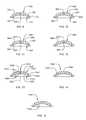
- FIG. 2is a top plan view of the valve member shown in FIG. 1 .
- FIGS. 3-6are cross-sectional views of nozzle outlet assemblies according to further exemplary embodiments.
- FIGS. 7 and 8are fragmentary cross-sectional views of a nozzle outlet in accordance with still further exemplary embodiments of the present invention.
- FIGS. 9-15are cross-sectional views of some additional exemplary valves according to the present invention.
- FIGS. 16 and 17are cross-sectional views of exemplary embodiments employing a vent-resisting baffle.
- FIG. 18is an enlarged perspective view of the vent-resisting baffle shown in FIG. 17 .
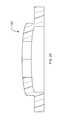
- FIG. 19is a perspective view of an alternative baffle member embodiment.
- FIG. 20is an enlarged view of a cross-slit valve similar to the valve appearing in FIG. 3 .
- FIG. 21is a cross-sectional view of an alternative outlet nozzle assembly.
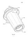
- FIG. 22is an isometric view, taken generally from above, of an exemplary embodiment nozzle tip having an internal vent-resisting member for retaining the valve within the nozzle tip.
- FIG. 23is an isometric view of the embodiment appearing in FIG. 22 , taken generally from below.
- FIGS. 24 and 25are bottom and top views, respectively, of the embodiment appearing in FIG. 22 .
- FIG. 26is a side cross-sectional view taken along the lines 26 - 26 appearing in FIG. 25 .
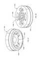
- FIGS. 27 and 28are isometric views, taken generally from below and above, respectively, of the retaining member.
- FIG. 29illustrates a prior art nozzle tip having an external retainer ring.
- FIG. 1there appears an exemplary embodiment of a pump assembly 10 incorporating an outlet valve assembly 12 according to the present invention.
- the pump assembly 10includes a resiliently flexible dome or bubble 14 defining a reservoir or chamber 16 for holding a charge of product to be dispensed.
- Exemplary fluids to be dispensedinclude, without limitation, liquid soap, shampoo, body wash, hand cream solutions, lotions or lotion soaps, gels, shaving cream, hand sanitizers, or any other flowable liquid.
- the chamber 16includes an inlet 18 and an outlet 20 .
- the inlet 18 of the chamber 16is fluidically coupled to a source of product, preferably a flexible bag (not shown) containing the product to be dispensed via an inlet nipple 22 .
- a source of productpreferably a flexible bag (not shown) containing the product to be dispensed via an inlet nipple 22 .
- the preferred bag-in-box embodimentis a closed system and venting is unnecessary, since pressure in the bag is maintained as the bag collapses upon itself.
- a one-way valvesuch as a ball (not shown) held in close proximity to the inlet 18 via a perforated retainer (not shown) may be provided to prevent fluid from passing from the chamber 16 back into the inlet nozzle 18 during operation.
- the hemispherical bubble 14is secured to a cavity back wall 24 via a retaining ring 26 .
- the chamber outlet 20is fluidically coupled a pump outlet nipple 28 via a conduit 30 defining a flow passageway 32 .
- An outlet valve assembly 12includes an outlet nozzle 34 having an axial bore or channel 36 therein and a counterbore 38 , and which is coaxially aligned with the outlet nipple 28 .
- a slit valve 40is seated in the counterbore 38 , which defines a sleeve portion for receiving the outlet nipple 28 and an internal stop or shoulder 39 .
- the valve 40includes a valve head or membrane portion 42 which is bounded by a peripheral sealing edge or flange 44 . The peripheral edge 44 is compressed between the end edge surface of the outlet nozzle 28 and the base of the counterbore portion 38 of the outlet nozzle 12 to provide a sealing engagement and prevent fluid from flowing around the valve member 40 .
- the valve assemblyis shown in connection with a dome-type pump, it will be recognized that the nozzle assembly may be used other pump types, such as tube-type pumps and others.
- the valve head portion 42includes one or more slits 46 forming an orifice and defining flexible flaps 47 .
- the membrane 42is formed of a resiliently flexible material, such as flexible plastic, rubber, elastomers, silicone rubber, and the like.
- Exemplary resilient or flexible materials which may be used in making the valve memberinclude, for example, polyurethane, polyisoprene, polybutadiene, neoprene, butadiene-acrylonitrile copolymers, ethylene-butadiene block copolymers, ethylene-propylene based copolymers including ethylene propylene diene terpolymer (EPDM), natural rubber, polychloroprene rubber, polyisoprene-isobutylene copolymers, silicone rubber, styrene-acrylonitrile copolymers, styrene-butadiene copolymers, styrene-isoprene copolymers, styrene-maleic anhydride copolymers, fluoroelastomers, polyolefins, and so forth, as well as blends thereof.
- EPDMethylene propylene diene terpolymer
- valve headmaintains the flaps 46 in the closed position, thereby preventing fluid flow therethrough until the fluid pressure reaches some threshold value, i.e., when the dispenser actuator is depressed, whereupon the flaps 46 separate and the product is expelled through the valve orifice 46 .
- the outlet nipple 28is coaxially or telescopically received within the counterbore 38 of the outlet nozzle 34 .
- the inner diameter of the counterbore region 38 and the outer diameter of the outlet nipple 28are sized to provide a friction or interference fit therebetween.
- the outlet nipple 28 outer surface and the counterbore 38 inner surfacemay optionally include aligned and mating or complimentary surface features.
- the outlet nipple 28includes raised annular ribs or protrusions 48 which engage complimentary annular channels or depressions 50 formed in the counterbore region 38 .
- the complimentary surface features 48 and 50provide a snap fit between the nozzle outlet 34 and the nipple outlet 28 and ensure sufficient compression of the peripheral edge 44 to prevent fluid from flowing therearound during operation.
- the respective positions of the complimentary protrusions and depressionscould be reversed.
- Other methods for securing the pump outlet nipple 28 and the connector sleeve portion of the nozzle 34include the use of an adhesive, cross-hatching, texturing, or other surface modification of the counterbore 38 inner surface and/or outlet 28 outer surface, providing complimentary helical threads for rotational engagement, and so forth.
- the nozzle outlet 34may additionally include one or more exterior surface features (not shown) such as projections, fins, particular geometric shape, etc., which provides a keying function to ensure proper installation of the pump within the dispenser and/or to enable the pump assembly 10 to be keyed to fit a specific dispenser pump of like or mating configuration.
- exterior surface featuressuch as projections, fins, particular geometric shape, etc.
- the use of a separately attachable nozzle outlet 34allows a common pump assembly to be readily adapted to fit any desired key configuration by installing an appropriately keyed nozzle outlet.
- an alternative outlet nozzle assembly 112including an outlet nozzle 134 defining an axial bore 136 and an annular protrusion 138 forming an internal stop member which extends radially into the bore 136 .
- the pump outlet nipple 28is telescopically received within the axial bore 136 of the outlet nozzle 134 .
- the inner diameter of the nozzle 136 and the outer diameter of the outlet nipple 28are sized to provide a friction or interference fit.
- a valve member 140includes a valve head portion 142 and peripheral edge 144 as detailed above and the peripheral edge 144 is sealingly retained between the end of the outlet nipple 28 and the annular ring 138 .
- An enlarged view of an alternative valve 140 ′ similar to the valve 140appears in FIG. 20 .
- the outlet nipple 28 outer surface and the outlet nozzle 134 inner surfacemay include optional aligned and mating surface features, e.g., raised annular ribs or protrusions 48 which engage complimentary annular channels or depressions 50 , as described above.
- the peripheral flange portion 144 of the valve member 140 as shown in FIG. 3is defined on the inward facing surface thereof by an peripheral annular notch 141 formed on the inward facing surface of the valve member 140 which is adapted to receive the distal end of the outlet nipple 28 .
- Thispermits sealing engagement of the edge 144 without distortion of the valve head member.
- the annular notch 141also serves to define a region 143 of reduced cross-sectional thickness with increased flexibility and/or articulability, thereby reducing the pressure necessary to cause the valve 140 to open.
- a nozzle assembly 212including a nozzle outlet 134 having an inwardly extending retaining ridge 138 and which telescopically engages a pump outlet nipple 28 .
- the nozzle assembly 212additionally includes a valve 240 .
- the valve 240according to a further embodiment of the present invention includes a peripheral flange portion 244 bounding a valve head portion 242 .
- the flange portion 244is sealingly retained between the outlet nipple 28 and the ridge 138 .
- the valve head portion 242includes an inward or upstream facing surface 245 and exterior or downstream facing surface 247 which is opposite the surface 245 .
- the inwardly facing surface 245is convex and the exterior facing surface 247 is generally concave and cusped in cross-sectional shape. That is, the interior surface 247 cross-sectional shape is defined by a series of curves or arcs defining regions of reduced thickness 243 and cusps 249 defining regions of increased thickness.
- the regions of reduced thickness 243increase the flexibility and/or articulability of the valve 240 and reduce the pressure necessary to cause the valve 240 to open.
- a nozzle assembly 312including a nozzle outlet 134 having an inwardly extending retaining ridge 138 and which telescopically engages a pump outlet nipple 28 .
- the nozzle assembly 312additionally includes a valve 340 .
- the valve 340according to yet a further embodiment of the present invention includes a peripheral flange portion 344 bounding a valve head portion 342 .
- the flange portion 344is sealingly retained between the outlet nipple 28 and the ridge 138 .
- the valve 340includes a peripheral annular notch 341 receiving the distal end of the pump outlet nipple 28 .
- a second annular notch or groove 351is disposed on the valve head portion 342 , radially inward from the peripheral notch 341 .
- the notch 351defines a region of reduced valve head thickness, thereby increasing the flexibility and/or articulability of the valve and reducing the pressure necessary to cause the valve to open and fluid to be expelled.
- the valve head portion 342also includes a first generally conical cavity 353 formed in the inward facing surface thereof and a second generally conical cavity 355 formed in the exterior facing surface of the valve head 342 .
- the conical cavities 353 , 355are axially aligned with the slits forming the valve orifice, with the apexes thereof being aligned and facing, whereby the thickness of the displaceable flaps is tapered toward the center of the orifice. This reduced thickness at the orifice reduces the pressure necessary to cause the flaps to open and expel the fluid therethough.
- the conical cavities described by way of reference to FIG. 3 and elsewhere hereinmay be replaced with other geometric configurations, such as frustoconical, pyramidical, frustopyramidical, and so forth.
- an outlet valve assembly 412including a nozzle outlet 134 having an inwardly extending retaining ridge 138 and which telescopically engages a pump outlet nipple 28 .
- the nozzle assembly 412additionally includes a valve 440 .
- the valve 440according to still a further embodiment of the present invention includes a peripheral flange portion 444 bounding a valve head portion 442 .
- the flange portion 444is sealingly retained between the outlet nipple 28 and the ridge 138 .
- the base surface 459 of the flange 444engages the ridge 138 and extends beyond the ridge 138 in the radially inward direction.
- the valve 440includes a peripheral annular notch 441 receiving the distal end of the pump outlet nipple 28 .
- a second annular notch or grooveis disposed on the valve head portion 442 radially inward from the peripheral notch 441 .
- the notch 451defines a region of reduced valve head thickness, thereby increasing the flexibility and/or articulability of the valve, thereby reducing the pressure necessary to cause the valve to open.
- the valve head portion 442also includes a first generally conical cavity 453 formed in the inward facing surface thereof and a second generally conical cavity 455 formed in the exterior facing surface of the valve head 442 .
- the conical cavities 453 , 455are axially aligned with the slits forming the valve orifice, with the apexes thereof being aligned and facing, whereby the thickness of the displaceable flaps is tapered toward the center of the orifice. This reduced thickness at the orifice reduces the pressure necessary to cause the flaps to open and expel the fluid therethough.
- FIG. 7there is shown a fragmentary view of an outlet nozzle assembly 512 , including a nozzle outlet 134 having an inwardly extending retaining ridge 138 and which telescopically engages a pump outlet nipple 528 .
- the nozzle assembly 512additionally includes a valve 540 .
- the valve 540according to another embodiment of the present invention includes a peripheral flange portion 544 bounding a valve head portion 542 . The flange portion 544 is sealingly retained between the outlet nipple 528 and the ridge 138 .
- the peripheral flange portion 544is defined on the inward facing surface thereof by a peripheral annular notch 541 which is adapted to receive the distal end of the outlet nipple 528 .
- the outlet nipple 528includes a distal end 529 , which is tapered or beveled on its radially inward edge.
- the angle, theta, of the bevelis preferably in the range of about 5-60 degrees, and preferably about 25-45 degrees, relative to the axial or flow direction 52 .
- the annular notch 541also serves to define a region 543 of reduced cross-sectional thickness with increased flexibility and/or articulability, thereby reducing the pressure necessary to cause the valve 540 to open during operation.
- FIG. 8there is shown a fragmentary view of a nozzle assembly 612 including a nozzle outlet 134 having an inwardly extending retaining ridge 138 and which telescopically engages a pump outlet nipple 28 .
- the nozzle assembly 612additionally includes a valve 640 .
- the valve 640is substantially as shown and described above by way of reference to the valve 340 shown in FIG. 5 , except that the conical cavities in the valve head orifice region are omitted.
- a peripheral flange portion 644bounds a valve head portion 642 . The flange portion 644 is sealingly retained between the outlet nipple 28 and the ridge 138 .
- the valve 640includes a peripheral annular notch 641 receiving the distal end of the pump outlet nipple 28 .
- a second annular notch or groove 651is disposed on the valve head radially inward from the peripheral notch 641 .
- the notch 651defines a region of reduced valve head thickness, thereby increasing the flexibility and/or articulability of the valve and reducing the pressure necessary to cause the valve to open and fluid to be expelled.
- the valve 740includes a peripheral flange portion 744 bounding a valve head portion 742 .
- the valve 740includes a peripheral annular notch 741 for receiving the distal end of the pump outlet nipple 28 (see FIGS. 1-8 ).
- the notch 741further defines a region 743 of reduced valve head thickness, thereby increasing the flexibility and/or articulability of the valve, and thereby reducing the pressure necessary to cause the valve to open.
- the valve head portion 742also includes a generally conical cavity 755 formed in an exterior facing surface 747 of the valve head 742 .
- the conical cavity 755is axially aligned with the slits forming the valve orifice, with the apex in the depicted embodiment extending roughly one-half of the cross sectional thickness of the valve head portion 742 .
- the thickness of the displaceable valve flapsis tapered toward the center of the orifice and reduces the pressure necessary to cause the flaps to open and expel the fluid therethough.
- the degree of taper and/or degree to which the conical cavity extends through the cross-sectional thickness of the valve head portionmay be varied in accordance with the product to be dispensed.
- the valve 840includes a peripheral flange portion 844 bounding a valve head portion 842 .
- the valve 840includes a peripheral annular notch 841 for receiving the distal end of the pump outlet nipple 28 (see FIGS. 1-8 ).
- the notch 841further defines a region 843 of reduced valve head thickness, thereby increasing the flexibility and/or articulability of the valve, and thereby reducing the pressure necessary to cause the valve to open.
- the valve head portion 842also includes a generally conical cavity 853 formed in an interior-facing surface 845 of the valve head 842 .
- the conical cavity 853is axially aligned with the slits forming the valve orifice, with the apex in the depicted embodiment extending roughly one-half of the cross sectional thickness of the valve head portion 842 .
- the thickness of the displaceable valve flapsis tapered toward the center of the orifice and reduces the pressure necessary to cause the flaps to open and expel the fluid therethough.
- the degree of taper and/or degree to which the conical cavity extends through the cross-sectional thickness of the valve head portionmay be varied in accordance with the product to be dispensed.
- valve 940including a peripheral flange portion 944 bounding a valve head portion 942 .
- the valve 940includes a peripheral annular notch 941 for receiving the distal end of a pump outlet nipple 28 (see FIGS. 1-8 ) and defining a region 943 of reduced valve head thickness, thereby increasing the flexibility and/or articulability of the valve and reducing the pressure necessary to cause the valve to open.
- the valve head portion 942also includes a first generally conical cavity 953 formed in the inward facing surface 945 thereof and a second generally conical cavity 955 formed in the exterior facing surface 947 thereof.
- FIG. 12illustrates a valve 940 ′ essentially as described above by way of reference to the valve 940 in FIG. 11 , but wherein cavities 953 ′ and 955 ′ are of differing taper and extend to a lesser degree through the valve head 942 ′ in the axial direction.
- FIG. 13there appears an outlet valve 1040 according to another embodiment of the present invention having a peripheral flange portion 1044 bounding a valve head portion 1042 .
- the valve 440includes a peripheral annular notch 1041 receiving the distal end of the pump outlet nipple 28 (see FIGS. 1-8 ).
- a series of concentric annular notches or grooves 1057are formed on the inward facing surface 1045 of the valve head 1042 .
- the annular channels 1057are concentric with an axial centerline 1052 of the valve 1040 .
- a series of annular notches or grooves 1059 concentric with the centerline 1052are formed on the outward facing surface 1047 of the valve head 1042 .
- the notch 1051 , the channels 1057 , and the channels 1059provide regions of reduced valve head thickness, thereby increasing the flexibility and/or articulability of the valve, thereby reducing the pressure necessary to cause the valve to open.
- the valve head portion 1042also includes a first generally conical cavity 1053 formed in the interiorly facing surface 1045 .
- the generally conical cavity 1053is axially aligned with the slits forming the valve orifice and extends through the majority of the valve head cross-sectional thickness. In this manner, the thickness of the displaceable flaps is tapered toward the center of the orifice to reduce the pressure necessary to cause the flaps to open.
- valve 14illustrates a valve 1040 ′ essentially as described above by way of reference to the valve 1040 in FIG. 13 , but wherein cavity 1053 ′ is of differing taper and extends to a lesser degree through the valve head 1042 ′ in the axial direction.
- the concentric annular groovesare depicted on both the interior and exterior valve head surfaces.
- the annular groovesmay be present on either the exterior surface only.
- a valve head 1140is shown having annular grooves 1159 formed on the exterior facing surface only.
- a like valve headis provided with annular grooves formed only on the interior facing surface.
- an outlet valve assembly 134includes a vent resistant member 54 located adjacent to an interior facing surface of a valve member 140 .
- the vent resistant member 54includes a generally disc-shaped baffle 56 having radially spaced-apart perforations 58 at its periphery. During operation, product flows through the perforations 58 and through the valve orifice.
- the baffle central portion 56prevents opening of the valve flaps in the inward direction, thereby preventing ingress of ambient air through the valve member.
- the perforated baffle 54may be integrally formed or comolded with the outlet nipple 28 or may be separately formed and secured in place via an adhesive or other fastening means.
- vent-resisting member 154is located adjacent to an interior facing surface of a valve member 140 having a valve head portion 142 and peripheral sealing edge 144 .
- the vent resistant member 154includes a generally disc-shaped baffle 156 having radially spaced-apart perforations 158 at its periphery, an axially extending annular sidewall 160 , and a peripheral flange 162 .
- the peripheral flange 160is retained along with the valve sealing edge 144 between the distal end of the outlet nipple 28 and the annular protrusion 138 .
- vent-resisting member 254including transversely extending bars or baffles 256 defining perforations 258 .
- the vent-resistant member 254also includes an axially extending annular sidewall 260 and a peripheral retaining flange 262 .
- the baffles 256are adjacent to the inward facing surface of the valve member to prevent the valve flaps from opening inwardly, thereby preventing venting of ambient air following a dispensing operation.
- FIG. 21there appears an alternative outlet nozzle assembly including a male outlet nozzle 234 received within a pump outlet nipple 128 defining an axial bore 236 .
- the pump outlet 128includes an annular protrusion 238 forming an internal stop member which extends radially into the bore 236 .
- the pump outlet nipple 128coaxially receives the outlet nozzle 234 within the axial bore 236 of the outlet nipple 128 .
- the inner diameter of the nipple 128 and the outer diameter of the outlet nozzle 234are sized to provide a friction or interference fit.
- a valve member 140is sealingly retained between the end edge surface of the outlet nozzle 234 and the annular ring 238 .
- the outlet nozzle 234 and the pump outlet 128may be secured via a friction fit or any of the methods described above.
- the outlet nozzle 234 outer surface and the outlet nipple 128 inner surfaceinclude optional aligned and mating surface features as detailed above, e.g., raised annular ribs or protrusions 148 formed on the nozzle 234 outer surface which engage complimentary annular channels or depressions 150 on the outlet nipple surface inner surface.
- the relative positions of the protrusions 148 and channels 150may be reversed.
- the embodiment of FIG. 21may be adapted to employ other valve and/or internal stop configurations as described herein.
- vent-resistant members 21may be adapted to employ the vent-resistant members as detailed above, either by directly securing the same to the interior surface of the pump outlet or by providing a vent-resistant member having a retaining flange, e.g., as shown in FIGS. 18 and 19 , wherein the retaining flange is retained between the valve peripheral sealing ring and the internal stop member 238 .
- the pump tip 1200is preferably of a type for use with a tube-type pump dispenser although it will be appreciated that the pump tip 1200 shown may also be adapted for use with other pump types, such as a dome pump of the type shown in FIG. 1 .
- the pump tip 1200includes a nozzle 1234 , and outwardly extending tabs 1221 adapted to interface with a pump dispenser housing. It will be recognized that alternate tabs or other surface features may be provided which mate with complimentary or keyed features on the dispenser housing to accept lateral insertion of the pump tip while supporting and retaining the pump tip 1200 from downward movement.
- An upper or inlet end 1235 of the pump tip 1200is provided for coaxial and fluidic coupling with a pump tube (not shown).
- a narrowed diameter region or inward flange 1223 at an outlet end 1225 of the pump tip 1200defines a shoulder 1227 .
- a resiliently flexible cross-slit valve 1240includes a valve head or membrane portion 1242 having one or more slits 1246 and is bounded by a peripheral sealing edge or flange 1244 .
- the depicted valve 1240may be of the type shown, for example, in U.S. Pat. Nos. 5,213,236, 5,339,995, 5,377,877, 5,409,144, 5,439,143, 5,839,614, 5,890,621, 5,927,566, 5,944,234, 5,971,232, 6,112,951, 6,112,952, and 6,112,806.
- Such valvesare available from Liquid Molding Systems, Inc., of Midland, Mich.
- any of the aforementioned valves shown and described above by way of reference to FIGS. 1-21may be employed.
- the valve 1240is preferably seated near the outlet end of the nozzle 1234 . Shortening the distance between the valve and the nozzle outlet reduces the surface area of the nozzle inner surface that is downstream of the valve. This reduced surface area for material collection, in turn, reduces the likelihood of material buildup, “jamming,” stalactite formation, dripping, or deflected shots.
- the peripheral edge 1244 of the valve 1240is retained on the shoulder 1227 by a vent-resistant member 1254 having a central, generally disc-shaped baffle 1256 and a plurality of openings 1258 therearound.
- An axially extending annular sidewall 1260extends downward (in the orientation shown in FIG. 26 ) therefrom.
- the peripheral valve edge 1244is retained between the shoulder 1227 and the axially-extending sidewall 1260 .
- Alternative vent-resisting baffle configuresare also contemplated and may be as shown in FIGS. 17-19 .
- a rigid retaining ringe.g., wherein the central vent-resisting baffle portion 1256 is omitted.
- the valve 1240 and vent-resistant member 1254are inserted into the nozzle from the upper end 1235 .
- the vent-resisting member 1254may be retained within the nozzle 1234 via a friction fit, or, more preferably via a snap fit engagement.
- the member 1254is urged past an annular rib 1261 which is formed on the interior surface 1263 of the nozzle 1234 and provides a snap fit retention of the member 1254 .
- the rib 1261engages the upper edge of the vent-resisting baffle.
- a snap fit engagementmay be provided by means of a complimentary peripheral groove or depression adapted to receive the rib 1261 .
- valve peripheral edge 1244has a generally tapered or dovetailed cross-sectional shape and the shoulder 1227 and downward facing surface 1263 of the annular wall 1260 cooperate to define a complimentary annular recess or channel 1265 for secure retention of the valve peripheral edge 1244 .
- the rib 1261may be positioned such that the vent-resistant member 1254 compresses the valve peripheral edge 1244 to provide a sealing engagement therebetween to prevent fluid from flowing around the valve member 1240 .
- the annular sidewalls 1260may be slightly inwardly tapered to facilitate axially sliding movement of the member 1254 past the rib 1261 and into the locked position to assemble the unit.
- the baffle 1256is adjacent to the inward facing surface of the valve member 1240 to prevent the valve flaps from opening inwardly, thereby preventing venting of ambient air following a dispensing operation.
Landscapes
- Engineering & Computer Science (AREA)
- General Engineering & Computer Science (AREA)
- Mechanical Engineering (AREA)
- Containers And Packaging Bodies Having A Special Means To Remove Contents (AREA)
Abstract
Description
Claims (20)
Priority Applications (1)
| Application Number | Priority Date | Filing Date | Title |
|---|---|---|---|
| US14/987,941US9714714B2 (en) | 2004-09-09 | 2016-01-05 | Nozzle tip with slit valve for fluid dispenser |
Applications Claiming Priority (5)
| Application Number | Priority Date | Filing Date | Title |
|---|---|---|---|
| US60823904P | 2004-09-09 | 2004-09-09 | |
| US11/220,018US20060049208A1 (en) | 2004-09-09 | 2005-09-06 | Slit valves and dispensing nozzles employing same |
| US11/854,360US8899449B2 (en) | 2004-09-09 | 2007-09-12 | Nozzle tip with slit valve for fluid dispenser |
| US14/527,263US9254498B2 (en) | 2004-09-09 | 2014-10-29 | Nozzle tip with slit valve for fluid dispenser |
| US14/987,941US9714714B2 (en) | 2004-09-09 | 2016-01-05 | Nozzle tip with slit valve for fluid dispenser |
Related Parent Applications (1)
| Application Number | Title | Priority Date | Filing Date |
|---|---|---|---|
| US14/527,263ContinuationUS9254498B2 (en) | 2004-09-09 | 2014-10-29 | Nozzle tip with slit valve for fluid dispenser |
Publications (2)
| Publication Number | Publication Date |
|---|---|
| US20160131267A1 US20160131267A1 (en) | 2016-05-12 |
| US9714714B2true US9714714B2 (en) | 2017-07-25 |
Family
ID=46329317
Family Applications (3)
| Application Number | Title | Priority Date | Filing Date |
|---|---|---|---|
| US11/854,360Active2029-07-28US8899449B2 (en) | 2004-09-09 | 2007-09-12 | Nozzle tip with slit valve for fluid dispenser |
| US14/527,263Expired - LifetimeUS9254498B2 (en) | 2004-09-09 | 2014-10-29 | Nozzle tip with slit valve for fluid dispenser |
| US14/987,941Expired - Fee RelatedUS9714714B2 (en) | 2004-09-09 | 2016-01-05 | Nozzle tip with slit valve for fluid dispenser |
Family Applications Before (2)
| Application Number | Title | Priority Date | Filing Date |
|---|---|---|---|
| US11/854,360Active2029-07-28US8899449B2 (en) | 2004-09-09 | 2007-09-12 | Nozzle tip with slit valve for fluid dispenser |
| US14/527,263Expired - LifetimeUS9254498B2 (en) | 2004-09-09 | 2014-10-29 | Nozzle tip with slit valve for fluid dispenser |
Country Status (1)
| Country | Link |
|---|---|
| US (3) | US8899449B2 (en) |
Cited By (1)
| Publication number | Priority date | Publication date | Assignee | Title |
|---|---|---|---|---|
| US20220331823A1 (en)* | 2019-09-25 | 2022-10-20 | Kao Corporation | Dispenser |
Families Citing this family (46)
| Publication number | Priority date | Publication date | Assignee | Title |
|---|---|---|---|---|
| JP3957640B2 (en)* | 2002-02-21 | 2007-08-15 | アイシン化工株式会社 | Wide slit nozzle and coating method with wide slit nozzle |
| US9518899B2 (en) | 2003-08-11 | 2016-12-13 | Sakura Finetek U.S.A., Inc. | Automated reagent dispensing system and method of operation |
| US8899449B2 (en)* | 2004-09-09 | 2014-12-02 | Warren S. Daansen | Nozzle tip with slit valve for fluid dispenser |
| US7784652B2 (en)* | 2007-03-27 | 2010-08-31 | Liquid Molding Systems, Inc. | Dispensing valve with hydraulic hammer resistance |
| EP2234897B1 (en)* | 2008-01-29 | 2012-03-07 | James Alexander Corporation | Dispenser |
| US8678249B2 (en) | 2008-02-21 | 2014-03-25 | Aptargroup, Inc. | Valve mounting assembly with slit misalignment prevention feature |
| US8316890B2 (en)* | 2008-11-11 | 2012-11-27 | Aptargroup, Inc. | Port closure system with hydraulic hammer resistance |
| US8007468B2 (en)* | 2009-07-13 | 2011-08-30 | Navilyst Medical, Inc. | Method to secure an elastic component in a valve |
| US8752732B2 (en)* | 2011-02-01 | 2014-06-17 | Sakura Finetek U.S.A., Inc. | Fluid dispensing system |
| ES2546493T3 (en) | 2011-05-04 | 2015-09-24 | Aptargroup, Inc. | Hole closure system for use with a drilling / filling / emptying tool |
| US8932543B2 (en) | 2011-09-21 | 2015-01-13 | Sakura Finetek U.S.A., Inc. | Automated staining system and reaction chamber |
| JP5333611B2 (en)* | 2012-01-10 | 2013-11-06 | サーモス株式会社 | Beverage container |
| US9206797B2 (en)* | 2012-11-29 | 2015-12-08 | Meadwestvaco Calmar Netherlands Bv | Bellows for a pump device |
| HK1218635A1 (en)* | 2013-01-16 | 2017-03-03 | 无限医学工程有限责任公司 | Pressure controlled magnetic valve for a catheter |
| FR3001719B1 (en) | 2013-02-07 | 2016-02-05 | Gb Dev | FLUID DISPENSING DEVICE AND METHOD FOR MANUFACTURING SUCH A DEVICE. |
| CN103405344B (en)* | 2013-05-24 | 2015-09-23 | 孙庆扬 | A kind of feeding bottle with return-air function |
| FR3011826B1 (en)* | 2013-10-10 | 2015-12-25 | Karine Courtin | DEVICE FOR DISPENSING AND PROTECTING FLUID COMPRISING A SLOTTED SHUTTER |
| US9488286B2 (en)* | 2013-10-24 | 2016-11-08 | Ecolab Usa Inc. | Single piece three-way elastomeric valve |
| CN104722449A (en)* | 2015-04-09 | 2015-06-24 | 京东方科技集团股份有限公司 | Coating head, coating equipment and manufacturing method of touch display panel |
| EP3285729B1 (en) | 2015-04-23 | 2019-12-18 | The Procter and Gamble Company | Concentrated personal cleansing compositions and methods |
| US20160310387A1 (en) | 2015-04-23 | 2016-10-27 | The Procter & Gamble Company | Concentrated Personal Cleansing Compositions and Methods |
| EP3285725B1 (en) | 2015-04-23 | 2019-12-04 | The Procter and Gamble Company | Concentrated personal cleansing compositions |
| MX376295B (en) | 2015-04-23 | 2025-03-07 | Procter & Gamble | CONCENTRATED COMPOSITIONS FOR PERSONAL CLEANING AND METHODS. |
| USD772602S1 (en) | 2015-05-27 | 2016-11-29 | Gregory L. Indruk | Tip for dispenser pump |
| USD768489S1 (en) | 2015-07-10 | 2016-10-11 | Gregory L. Indruk | Tip for dispenser pump |
| US11596580B2 (en)* | 2016-03-03 | 2023-03-07 | Qingyang SUN | Nursing bottle having air returning function |
| AT518627B1 (en)* | 2016-05-12 | 2021-09-15 | Joma Kunststofftechnik Gmbh | Dispenser |
| WO2018034932A1 (en)* | 2016-08-18 | 2018-02-22 | Kci Licensing, Inc. | In-line diagnostic tool for negative-pressure therapy |
| ES3014858T3 (en)* | 2016-09-06 | 2025-04-25 | Trisco ICAP Pty Ltd | Storage and delivery system |
| GB2559103A (en)* | 2016-10-14 | 2018-08-01 | Bradley Mark | Dispensing system |
| FR3057467B1 (en)* | 2016-10-17 | 2018-12-07 | IFP Energies Nouvelles | PROCESS FOR PURIFYING AQUEOUS SOLUTION COMPRISING DIETHYLACETAL |
| US11185486B2 (en) | 2016-10-21 | 2021-11-30 | The Procter And Gamble Company | Personal cleansing compositions and methods |
| CN109843253B (en) | 2016-10-21 | 2022-11-08 | 宝洁公司 | Skin cleansing compositions and methods |
| FR3062320B1 (en)* | 2017-02-02 | 2019-03-29 | Aptar France Sas | DISPENSER DROPPER. |
| US10806686B2 (en) | 2017-02-17 | 2020-10-20 | The Procter And Gamble Company | Packaged personal cleansing product |
| US10675231B2 (en)* | 2017-02-17 | 2020-06-09 | The Procter & Gamble Company | Packaged personal cleansing product |
| US10293353B2 (en) | 2017-04-25 | 2019-05-21 | Gpcp Ip Holdings Llc | Automated flowable material dispensers and related methods for dispensing flowable material |
| RU2742443C1 (en)* | 2017-10-23 | 2021-02-05 | Аптаргруп, Инк. | Valve |
| US10591932B2 (en) | 2017-11-08 | 2020-03-17 | Carefusion Corporation | Diaphragm check valve |
| DE102018208110A1 (en)* | 2018-05-23 | 2019-11-28 | F. Holzer Gmbh | Dispensing head and dispensing device for metered dispensing of liquid preparations and possible uses |
| US11027909B2 (en) | 2018-08-15 | 2021-06-08 | Gpcp Ip Holdings Llc | Automated flowable material dispensers and related methods for dispensing flowable material |
| CN109854788A (en)* | 2018-11-27 | 2019-06-07 | 四川嘉泰华动力设备有限公司 | A kind of new-type vibrationproof movable valve |
| IT201900006833A1 (en)* | 2019-05-14 | 2020-11-14 | Soremartec Sa | DISPENSER GROUP FOR A FOOD CREAM DOSING MACHINE |
| US12064063B2 (en) | 2019-09-23 | 2024-08-20 | Gpcp Ip Holdings Llc | Automated toilet seat cover dispenser |
| WO2021059696A1 (en) | 2019-09-25 | 2021-04-01 | 花王株式会社 | Dispenser |
| US11092254B1 (en)* | 2020-03-26 | 2021-08-17 | Jose Luis Rueda Calvet | Self-sealing valve for an inflatable body and method for manufacturing same |
Citations (82)
| Publication number | Priority date | Publication date | Assignee | Title |
|---|---|---|---|---|
| US2328382A (en)* | 1941-10-08 | 1943-08-31 | Jesse D Langdon | Flexible check valve and vacuum breaker |
| US2347988A (en)* | 1943-10-20 | 1944-05-02 | Ormonde J Burke | Valve construction |
| US2524764A (en)* | 1944-04-12 | 1950-10-10 | Adrian P Burke | Valve construction |
| US2598002A (en)* | 1946-08-20 | 1952-05-27 | Jesse D Langdon | Check valve construction |
| US2642259A (en)* | 1947-10-25 | 1953-06-16 | Manitowoc Shipbuilding Company | Valve |
| US2662724A (en)* | 1948-12-27 | 1953-12-15 | Kravagna Cut | Check valve |
| US2670757A (en)* | 1949-08-19 | 1954-03-02 | Delany Realty Corp | Combination check valve and union |
| US3118468A (en)* | 1961-04-20 | 1964-01-21 | Gen Electric | Resilient material check valve |
| US3160329A (en) | 1963-02-26 | 1964-12-08 | Radic Frank | Dispensing device |
| US3220611A (en) | 1964-08-14 | 1965-11-30 | Waldo H Zander | Wall mounted bracket and dispenser for collapsible tube |
| US3485419A (en) | 1968-01-30 | 1969-12-23 | Wilfred V Taylor | Fluent material dispenser |
| US3504699A (en) | 1967-03-20 | 1970-04-07 | Grimar Inc | Check valve |
| US4143853A (en)* | 1977-07-14 | 1979-03-13 | Metatech Corporation | Valve for use with a catheter or the like |
| US4155487A (en) | 1977-09-09 | 1979-05-22 | Blake William S | Trigger sprayer |
| US4621749A (en)* | 1984-02-21 | 1986-11-11 | Go-Jo Industries | Dispensing apparatus |
| US4646945A (en) | 1985-06-28 | 1987-03-03 | Steiner Company, Inc. | Vented discharge assembly for liquid soap dispenser |
| US4991745A (en) | 1989-04-25 | 1991-02-12 | Liquid Molding Systems, Inc. | Dispensing valve with trampoline-like construction |
| US4993452A (en)* | 1989-12-22 | 1991-02-19 | Cummins Engine Company, Inc. | Low pressure check valve |
| US5071017A (en) | 1991-02-15 | 1991-12-10 | Stuli Iene | Closure cap construction with slitted flexible diaphragm |
| US5105997A (en) | 1989-08-24 | 1992-04-21 | Shikokukakoki Co., Ltd. | Filling nozzle having a tube holding portion for holding a rubber tube |
| US5115950A (en) | 1991-01-14 | 1992-05-26 | Seaquist Closures A Divison Of Pittway Corporation | Dispensing closure with unitary structure for retaining a pressure-actuated flexible valve |
| US5213236A (en) | 1991-12-06 | 1993-05-25 | Liquid Molding Systems, Inc. | Dispensing valve for packaging |
| US5271531A (en) | 1991-01-14 | 1993-12-21 | Seaquist Closures, A Division Of Pittway Corp. | Dispensing closure with pressure-actuated flexible valve |
| US5409144A (en) | 1991-12-06 | 1995-04-25 | Liquid Molding Systems Inc. | Dispensing valve for packaging |
| US5464125A (en) | 1994-06-16 | 1995-11-07 | Daansen; Warren S. | Dispensing apparatus having a pump tube |
| US5501372A (en)* | 1994-05-27 | 1996-03-26 | Daansen; Warren S. | Pump tip for fluid dispenser |
| US5531363A (en) | 1994-06-10 | 1996-07-02 | Aptargroup, Inc. | Dispensing closure cartridge valve system |
| US5626262A (en) | 1995-06-07 | 1997-05-06 | Redmond Products, Inc. | Dispensing container with drainage passages |
| US5655687A (en) | 1995-06-07 | 1997-08-12 | Redmond Products, Inc. | Base end dispensing container with travel cap |
| US5676289A (en) | 1996-04-04 | 1997-10-14 | Aptargroup, Inc. | Valve-controlled dispensing closure with dispersion baffle |
| US5680969A (en) | 1995-12-18 | 1997-10-28 | Aptargroup, Inc. | Closure with dispensing valve and separate releasable internal shipping seal |
| US5730336A (en) | 1996-01-02 | 1998-03-24 | Cascade Designs, Inc. | Dispensing valve for a flexible liquid container |
| US5743443A (en) | 1995-05-17 | 1998-04-28 | Georg Menshen Gmbh & Co. Kg | Slit valve for closing off containers |
| US5788108A (en) | 1995-12-01 | 1998-08-04 | Aptargroup, Inc. | Dispensing closure with retractable lid |
| US5839614A (en) | 1991-12-06 | 1998-11-24 | Aptar Group, Inc. | Dispensing package |
| US5897033A (en) | 1997-06-20 | 1999-04-27 | Yoshino Kogyosho Co., Ltd. | Container having slit valve |
| US5904275A (en) | 1994-05-19 | 1999-05-18 | Zeller Plastik Gmbh | Closure with self-closing valve |
| US5911344A (en) | 1997-11-21 | 1999-06-15 | Courtaulds Packaging Inc. | Rigid thermoplastic squeeze container having self-sealing dispensing valve |
| US5927567A (en) | 1996-11-12 | 1999-07-27 | Owens-Illinois Closure Inc. | Dispensing closure and method of making |
| US5938086A (en) | 1998-11-05 | 1999-08-17 | Aptargroup, Inc. | Container and closure with non-rising rotatable housing, dispensing valve, and separate releasable internal shipping seal |
| US6006960A (en) | 1998-10-28 | 1999-12-28 | Aptargroup, Inc. | Dispensing structure which has a lid with a pressure-openable valve |
| US6045004A (en) | 1998-03-20 | 2000-04-04 | Aptargroup, Inc. | Dispensing structure with dispensing valve and barrier penetrator |
| US6053194A (en) | 1999-09-10 | 2000-04-25 | S. C. Johnson & Son, Inc. | Duckbilled check valves and methods of making and using same |
| US6062435A (en) | 1999-05-06 | 2000-05-16 | Aptargroup, Inc. | Valved dispensing system with priming liquid loss prevention |
| US6065642A (en) | 1998-12-09 | 2000-05-23 | Aptargroup, Inc. | Non-venting valve and dispensing package for fluid products and the like |
| US6089411A (en) | 1996-02-29 | 2000-07-18 | L'oreal | Dispensing head and unit for a product with a liquid-to-viscous consistency comprising a flow reducer, and method of manufacturing same |
| US6095381A (en) | 1995-09-05 | 2000-08-01 | Zeller Plastik Gmbh | Self-closing seal with a sealing membrane |
| US6095382A (en) | 1998-09-21 | 2000-08-01 | Aptargroup, Inc. | Container and closure with dispensing valve and separate releasable internal shipping seal |
| US6112952A (en) | 1999-05-06 | 2000-09-05 | Aptargroup, Inc. | Valved dispensing system with hydraulic hammer protection for the valve |
| US6142343A (en) | 1998-12-30 | 2000-11-07 | Steris Inc | Cap and dust cover for an antiseptic soap dispenser |
| US6152330A (en) | 1999-02-11 | 2000-11-28 | Chester Labs, Inc. | Hinged dispenser housing |
| US6186374B1 (en) | 1999-11-02 | 2001-02-13 | Seaquist Closures Foreign, Inc. | Dispensing structure which has a lid with a push-in mounted pressure-openable valve |
| US6189740B1 (en) | 1998-12-30 | 2001-02-20 | Steris Inc | Antiseptic soap dispenser with selectively variable dose |
| US6199725B1 (en) | 1999-06-11 | 2001-03-13 | Capsol Spa - Stampaggio Resine Termoplastiche | Automatically closing stopper for dispensing liquids from deformable containers |
| US6213355B1 (en) | 1996-05-30 | 2001-04-10 | Zeller Plastik Gmbh | Closure membrane and closure employing same |
| US6216916B1 (en) | 1999-09-16 | 2001-04-17 | Joseph S. Kanfer | Compact fluid pump |
| US6223956B1 (en) | 1998-10-01 | 2001-05-01 | Georg Menshen Gmbh & Co. Kg | Self-closing valve assembly for a dispensing opening of a container |
| US6230940B1 (en) | 1999-11-02 | 2001-05-15 | Seaquist Closures Foreign, Inc. | One-Piece dispensing system and method for making same |
| US6273305B1 (en) | 1997-08-21 | 2001-08-14 | Crown Cork & Seal Technologies Corporation | Valves for packaging containers |
| US6286732B1 (en) | 1998-08-28 | 2001-09-11 | Warren S. Daansen | Dispenser valve with increased flow capacity |
| US6293437B1 (en) | 2000-12-22 | 2001-09-25 | Seaquist Closures Foreign, Inc. | Valve with rolling sleeve |
| US6298554B1 (en) | 1998-04-02 | 2001-10-09 | Owens-Illinois Closure Inc. | Flexible vented self-sealing dispensing valve |
| US6325253B1 (en) | 2001-02-02 | 2001-12-04 | Owens-Illinois Closure Inc. | Self-closing fluid dispensing closure |
| US6394316B1 (en) | 1998-08-28 | 2002-05-28 | Warren S. Daansen | Bubble pump for dispensing particulate-ladened fluid |
| US6394315B1 (en) | 2000-05-08 | 2002-05-28 | Deb Ip Limited | Squeeze operated foam dispenser |
| US6405901B1 (en) | 2000-12-22 | 2002-06-18 | Seaquist Closures Foreign, Inc. | Valve with rolling sleeve |
| US6446844B1 (en) | 2001-12-18 | 2002-09-10 | Seaquist Closures Foreign, Inc. | Closure with internal flow control for a pressure openable valve in an extendable/retractable nozzle |
| US20020130139A1 (en) | 2001-03-13 | 2002-09-19 | Yasuyuki Shiraishi | Closing structure of a dispensing container |
| US6530504B2 (en) | 2001-03-02 | 2003-03-11 | Seaquist Closures Foreign, Inc. | Multiple orifice valve |
| US6543652B1 (en) | 1999-06-04 | 2003-04-08 | Crown Cork & Seal Technologies Corporation | Closure with dispensing valve |
| US6612468B2 (en) | 2000-09-15 | 2003-09-02 | Rieke Corporation | Dispenser pumps |
| US6616016B2 (en) | 2001-12-07 | 2003-09-09 | Seaquist Closures Foreign, Inc. | Closure with pressure-actuated valve and lid seal |
| US6619512B1 (en)* | 2002-07-16 | 2003-09-16 | Joseph S. Kanfer | Lock-out mechanism for dispenser |
| US6705492B2 (en) | 2002-06-27 | 2004-03-16 | Method Products, Inc. | Bottom-dispensing liquid soap dispenser |
| US6732889B2 (en) | 2002-02-06 | 2004-05-11 | Ishai Oren | Pouring spout for liquid containers, and liquid containers constructed therewith |
| US6749092B2 (en) | 2001-08-10 | 2004-06-15 | Seaquist Closures Foreign, Inc. | Deformable dispensing valve |
| US20050087555A1 (en) | 2003-10-28 | 2005-04-28 | Hatton Jason D. | Fluid dispensing components |
| US20060049208A1 (en) | 2004-09-09 | 2006-03-09 | Daansen Warren S | Slit valves and dispensing nozzles employing same |
| US20080035677A1 (en) | 2004-09-09 | 2008-02-14 | Daansen Warren S | Nozzle tip with slit valve for fluid dispenser |
| US7784652B2 (en) | 2007-03-27 | 2010-08-31 | Liquid Molding Systems, Inc. | Dispensing valve with hydraulic hammer resistance |
| US7806301B1 (en) | 2004-05-19 | 2010-10-05 | Joseph S Kanfer | Dome pump |
| US8490839B2 (en) | 2008-06-03 | 2013-07-23 | Taisei Kako Co., Ltd. | Filtering dispenser container |
- 2007
- 2007-09-12USUS11/854,360patent/US8899449B2/enactiveActive
- 2014
- 2014-10-29USUS14/527,263patent/US9254498B2/ennot_activeExpired - Lifetime
- 2016
- 2016-01-05USUS14/987,941patent/US9714714B2/ennot_activeExpired - Fee Related
Patent Citations (95)
| Publication number | Priority date | Publication date | Assignee | Title |
|---|---|---|---|---|
| US2328382A (en)* | 1941-10-08 | 1943-08-31 | Jesse D Langdon | Flexible check valve and vacuum breaker |
| US2347988A (en)* | 1943-10-20 | 1944-05-02 | Ormonde J Burke | Valve construction |
| US2524764A (en)* | 1944-04-12 | 1950-10-10 | Adrian P Burke | Valve construction |
| US2598002A (en)* | 1946-08-20 | 1952-05-27 | Jesse D Langdon | Check valve construction |
| US2642259A (en)* | 1947-10-25 | 1953-06-16 | Manitowoc Shipbuilding Company | Valve |
| US2662724A (en)* | 1948-12-27 | 1953-12-15 | Kravagna Cut | Check valve |
| US2670757A (en)* | 1949-08-19 | 1954-03-02 | Delany Realty Corp | Combination check valve and union |
| US3118468A (en)* | 1961-04-20 | 1964-01-21 | Gen Electric | Resilient material check valve |
| US3160329A (en) | 1963-02-26 | 1964-12-08 | Radic Frank | Dispensing device |
| US3220611A (en) | 1964-08-14 | 1965-11-30 | Waldo H Zander | Wall mounted bracket and dispenser for collapsible tube |
| US3504699A (en) | 1967-03-20 | 1970-04-07 | Grimar Inc | Check valve |
| US3485419A (en) | 1968-01-30 | 1969-12-23 | Wilfred V Taylor | Fluent material dispenser |
| US4143853A (en)* | 1977-07-14 | 1979-03-13 | Metatech Corporation | Valve for use with a catheter or the like |
| US4155487A (en) | 1977-09-09 | 1979-05-22 | Blake William S | Trigger sprayer |
| US4621749A (en)* | 1984-02-21 | 1986-11-11 | Go-Jo Industries | Dispensing apparatus |
| US4646945A (en) | 1985-06-28 | 1987-03-03 | Steiner Company, Inc. | Vented discharge assembly for liquid soap dispenser |
| US4991745A (en) | 1989-04-25 | 1991-02-12 | Liquid Molding Systems, Inc. | Dispensing valve with trampoline-like construction |
| US5105997A (en) | 1989-08-24 | 1992-04-21 | Shikokukakoki Co., Ltd. | Filling nozzle having a tube holding portion for holding a rubber tube |
| US4993452A (en)* | 1989-12-22 | 1991-02-19 | Cummins Engine Company, Inc. | Low pressure check valve |
| US5115950A (en) | 1991-01-14 | 1992-05-26 | Seaquist Closures A Divison Of Pittway Corporation | Dispensing closure with unitary structure for retaining a pressure-actuated flexible valve |
| US5271531A (en) | 1991-01-14 | 1993-12-21 | Seaquist Closures, A Division Of Pittway Corp. | Dispensing closure with pressure-actuated flexible valve |
| US5071017A (en) | 1991-02-15 | 1991-12-10 | Stuli Iene | Closure cap construction with slitted flexible diaphragm |
| US20020158083A1 (en) | 1991-12-06 | 2002-10-31 | Brown Paul E. | Dispensing valve |
| US5339995A (en) | 1991-12-06 | 1994-08-23 | Liquid Molding Systems, Inc. | Dispensing valve for packaging |
| US5377877A (en) | 1991-12-06 | 1995-01-03 | Liquid Molding Systems, Inc. | Dispensing valve for packaging |
| US5409144A (en) | 1991-12-06 | 1995-04-25 | Liquid Molding Systems Inc. | Dispensing valve for packaging |
| US5439143A (en) | 1991-12-06 | 1995-08-08 | Liquid Molding Systems, Inc. | Dispensing valve for packaging |
| US6279783B1 (en) | 1991-12-06 | 2001-08-28 | Seaquist Closures Foreign, Inc. | Dispensing valve |
| US5839614A (en) | 1991-12-06 | 1998-11-24 | Aptar Group, Inc. | Dispensing package |
| US5213236A (en) | 1991-12-06 | 1993-05-25 | Liquid Molding Systems, Inc. | Dispensing valve for packaging |
| US6427874B2 (en) | 1991-12-06 | 2002-08-06 | Seaquist Closures Foreign, Inc. | Dispensing valve |
| US5904275A (en) | 1994-05-19 | 1999-05-18 | Zeller Plastik Gmbh | Closure with self-closing valve |
| US5501372A (en)* | 1994-05-27 | 1996-03-26 | Daansen; Warren S. | Pump tip for fluid dispenser |
| US5531363A (en) | 1994-06-10 | 1996-07-02 | Aptargroup, Inc. | Dispensing closure cartridge valve system |
| US5464125A (en) | 1994-06-16 | 1995-11-07 | Daansen; Warren S. | Dispensing apparatus having a pump tube |
| US5743443A (en) | 1995-05-17 | 1998-04-28 | Georg Menshen Gmbh & Co. Kg | Slit valve for closing off containers |
| US5655687A (en) | 1995-06-07 | 1997-08-12 | Redmond Products, Inc. | Base end dispensing container with travel cap |
| US5626262A (en) | 1995-06-07 | 1997-05-06 | Redmond Products, Inc. | Dispensing container with drainage passages |
| US6095381A (en) | 1995-09-05 | 2000-08-01 | Zeller Plastik Gmbh | Self-closing seal with a sealing membrane |
| US5788108A (en) | 1995-12-01 | 1998-08-04 | Aptargroup, Inc. | Dispensing closure with retractable lid |
| US5680969A (en) | 1995-12-18 | 1997-10-28 | Aptargroup, Inc. | Closure with dispensing valve and separate releasable internal shipping seal |
| US5730336A (en) | 1996-01-02 | 1998-03-24 | Cascade Designs, Inc. | Dispensing valve for a flexible liquid container |
| US6089411A (en) | 1996-02-29 | 2000-07-18 | L'oreal | Dispensing head and unit for a product with a liquid-to-viscous consistency comprising a flow reducer, and method of manufacturing same |
| US5676289A (en) | 1996-04-04 | 1997-10-14 | Aptargroup, Inc. | Valve-controlled dispensing closure with dispersion baffle |
| US6213355B1 (en) | 1996-05-30 | 2001-04-10 | Zeller Plastik Gmbh | Closure membrane and closure employing same |
| US5927567A (en) | 1996-11-12 | 1999-07-27 | Owens-Illinois Closure Inc. | Dispensing closure and method of making |
| US5897033A (en) | 1997-06-20 | 1999-04-27 | Yoshino Kogyosho Co., Ltd. | Container having slit valve |
| US6273305B1 (en) | 1997-08-21 | 2001-08-14 | Crown Cork & Seal Technologies Corporation | Valves for packaging containers |
| US5911344A (en) | 1997-11-21 | 1999-06-15 | Courtaulds Packaging Inc. | Rigid thermoplastic squeeze container having self-sealing dispensing valve |
| US6045004A (en) | 1998-03-20 | 2000-04-04 | Aptargroup, Inc. | Dispensing structure with dispensing valve and barrier penetrator |
| US6298554B1 (en) | 1998-04-02 | 2001-10-09 | Owens-Illinois Closure Inc. | Flexible vented self-sealing dispensing valve |
| US6286732B1 (en) | 1998-08-28 | 2001-09-11 | Warren S. Daansen | Dispenser valve with increased flow capacity |
| US6394316B1 (en) | 1998-08-28 | 2002-05-28 | Warren S. Daansen | Bubble pump for dispensing particulate-ladened fluid |
| US6095382A (en) | 1998-09-21 | 2000-08-01 | Aptargroup, Inc. | Container and closure with dispensing valve and separate releasable internal shipping seal |
| US6223956B1 (en) | 1998-10-01 | 2001-05-01 | Georg Menshen Gmbh & Co. Kg | Self-closing valve assembly for a dispensing opening of a container |
| US6006960A (en) | 1998-10-28 | 1999-12-28 | Aptargroup, Inc. | Dispensing structure which has a lid with a pressure-openable valve |
| US6089419A (en) | 1998-10-28 | 2000-07-18 | Aptargroup, Inc. | Dispensing structure which has a lid with a pressure-openable valve |
| US5938086A (en) | 1998-11-05 | 1999-08-17 | Aptargroup, Inc. | Container and closure with non-rising rotatable housing, dispensing valve, and separate releasable internal shipping seal |
| US6065642A (en) | 1998-12-09 | 2000-05-23 | Aptargroup, Inc. | Non-venting valve and dispensing package for fluid products and the like |
| US6273296B1 (en) | 1998-12-09 | 2001-08-14 | Seaquist Closures Foreign, Inc. | Non-venting valve and dispensing package for fluid products and the like |
| US6189740B1 (en) | 1998-12-30 | 2001-02-20 | Steris Inc | Antiseptic soap dispenser with selectively variable dose |
| US6142343A (en) | 1998-12-30 | 2000-11-07 | Steris Inc | Cap and dust cover for an antiseptic soap dispenser |
| US6152330A (en) | 1999-02-11 | 2000-11-28 | Chester Labs, Inc. | Hinged dispenser housing |
| US6062435A (en) | 1999-05-06 | 2000-05-16 | Aptargroup, Inc. | Valved dispensing system with priming liquid loss prevention |
| US6112952A (en) | 1999-05-06 | 2000-09-05 | Aptargroup, Inc. | Valved dispensing system with hydraulic hammer protection for the valve |
| US6543652B1 (en) | 1999-06-04 | 2003-04-08 | Crown Cork & Seal Technologies Corporation | Closure with dispensing valve |
| US6199725B1 (en) | 1999-06-11 | 2001-03-13 | Capsol Spa - Stampaggio Resine Termoplastiche | Automatically closing stopper for dispensing liquids from deformable containers |
| US6053194A (en) | 1999-09-10 | 2000-04-25 | S. C. Johnson & Son, Inc. | Duckbilled check valves and methods of making and using same |
| US6216916B1 (en) | 1999-09-16 | 2001-04-17 | Joseph S. Kanfer | Compact fluid pump |
| US6186374B1 (en) | 1999-11-02 | 2001-02-13 | Seaquist Closures Foreign, Inc. | Dispensing structure which has a lid with a push-in mounted pressure-openable valve |
| US6230940B1 (en) | 1999-11-02 | 2001-05-15 | Seaquist Closures Foreign, Inc. | One-Piece dispensing system and method for making same |
| US6394315B1 (en) | 2000-05-08 | 2002-05-28 | Deb Ip Limited | Squeeze operated foam dispenser |
| US6612468B2 (en) | 2000-09-15 | 2003-09-02 | Rieke Corporation | Dispenser pumps |
| US6405901B1 (en) | 2000-12-22 | 2002-06-18 | Seaquist Closures Foreign, Inc. | Valve with rolling sleeve |
| US6293437B1 (en) | 2000-12-22 | 2001-09-25 | Seaquist Closures Foreign, Inc. | Valve with rolling sleeve |
| US6325253B1 (en) | 2001-02-02 | 2001-12-04 | Owens-Illinois Closure Inc. | Self-closing fluid dispensing closure |
| US6530504B2 (en) | 2001-03-02 | 2003-03-11 | Seaquist Closures Foreign, Inc. | Multiple orifice valve |
| US6672479B2 (en) | 2001-03-13 | 2004-01-06 | Taisai Kako Co., Ltd./Nihon Tenganyaku | Closing structure of a dispensing container |
| US20020130139A1 (en) | 2001-03-13 | 2002-09-19 | Yasuyuki Shiraishi | Closing structure of a dispensing container |
| US6749092B2 (en) | 2001-08-10 | 2004-06-15 | Seaquist Closures Foreign, Inc. | Deformable dispensing valve |
| US6616016B2 (en) | 2001-12-07 | 2003-09-09 | Seaquist Closures Foreign, Inc. | Closure with pressure-actuated valve and lid seal |
| US6446844B1 (en) | 2001-12-18 | 2002-09-10 | Seaquist Closures Foreign, Inc. | Closure with internal flow control for a pressure openable valve in an extendable/retractable nozzle |
| US6732889B2 (en) | 2002-02-06 | 2004-05-11 | Ishai Oren | Pouring spout for liquid containers, and liquid containers constructed therewith |
| US6705492B2 (en) | 2002-06-27 | 2004-03-16 | Method Products, Inc. | Bottom-dispensing liquid soap dispenser |
| US6619512B1 (en)* | 2002-07-16 | 2003-09-16 | Joseph S. Kanfer | Lock-out mechanism for dispenser |
| US20070080177A1 (en) | 2003-10-28 | 2007-04-12 | Seaquist Closures Foreign, Inc. | Fluid dispensing components |
| US20050087555A1 (en) | 2003-10-28 | 2005-04-28 | Hatton Jason D. | Fluid dispensing components |
| US7806301B1 (en) | 2004-05-19 | 2010-10-05 | Joseph S Kanfer | Dome pump |
| US20060049208A1 (en) | 2004-09-09 | 2006-03-09 | Daansen Warren S | Slit valves and dispensing nozzles employing same |
| US20080035677A1 (en) | 2004-09-09 | 2008-02-14 | Daansen Warren S | Nozzle tip with slit valve for fluid dispenser |
| US8899449B2 (en) | 2004-09-09 | 2014-12-02 | Warren S. Daansen | Nozzle tip with slit valve for fluid dispenser |
| US20150048121A1 (en) | 2004-09-09 | 2015-02-19 | Warren S. Daansen | Nozzle tip with slit valve for fluid dispenser |
| US9254498B2 (en)* | 2004-09-09 | 2016-02-09 | Warren S. Daansen | Nozzle tip with slit valve for fluid dispenser |
| US7784652B2 (en) | 2007-03-27 | 2010-08-31 | Liquid Molding Systems, Inc. | Dispensing valve with hydraulic hammer resistance |
| US8490839B2 (en) | 2008-06-03 | 2013-07-23 | Taisei Kako Co., Ltd. | Filtering dispenser container |
Cited By (2)
| Publication number | Priority date | Publication date | Assignee | Title |
|---|---|---|---|---|
| US20220331823A1 (en)* | 2019-09-25 | 2022-10-20 | Kao Corporation | Dispenser |
| US12233428B2 (en)* | 2019-09-25 | 2025-02-25 | Kao Corporation | Dispenser |
Also Published As
| Publication number | Publication date |
|---|---|
| US20080035677A1 (en) | 2008-02-14 |
| US8899449B2 (en) | 2014-12-02 |
| US20150048121A1 (en) | 2015-02-19 |
| US9254498B2 (en) | 2016-02-09 |
| US20160131267A1 (en) | 2016-05-12 |
Similar Documents
| Publication | Publication Date | Title |
|---|---|---|
| US9714714B2 (en) | Nozzle tip with slit valve for fluid dispenser | |
| US20060049208A1 (en) | Slit valves and dispensing nozzles employing same | |
| US7654419B2 (en) | Dispenser having elastomer discharge valve | |
| US6557736B1 (en) | Pivoting piston head for pump | |
| CN101674889B (en) | Liquid dispensing device with diaphragm valve and method for assembling said valve | |
| US6971553B2 (en) | Pump for dispensing flowable material | |
| US5938082A (en) | Container assembly having snap-fit container connection | |
| US8365962B2 (en) | Lever spray pump | |
| US7249694B2 (en) | Valve mechanism for tube-type fluid container | |
| CN103619488B (en) | improved trigger sprayer valve | |
| US4249681A (en) | Leak-proof sprayer | |
| EP1716928B1 (en) | Dispenser having slit valve forming an air tight spout | |
| JP2006517858A (en) | Dispenser pump | |
| US20100294805A1 (en) | Dispenser for dispensing liquid or pasty materials | |
| US6273128B1 (en) | Apparatus for controlling the flow of fluid | |
| EP1388500B1 (en) | Pump dispenser having an improved discharge valve | |
| AU2002238562A1 (en) | Foamer | |
| EP1370366A2 (en) | Foamer | |
| CN1802220B (en) | Pump-action nozzle device and method of manufacturing the same | |
| AU2010245905A1 (en) | Vented valve assembly | |
| CN107249754A (en) | Actuation system for fluid substance dispensing system | |
| US11426034B2 (en) | Reduced force, sealing vent for squeeze foamer | |
| MXPA05006300A (en) | Improvements in or relating to pump-action nozzle devices. | |
| CN112218726B (en) | Trigger sprayer without metal parts | |
| JPH03229660A (en) | Spray cap |
Legal Events
| Date | Code | Title | Description |
|---|---|---|---|
| AS | Assignment | Owner name:DAANSEN, TRUSTEE OF THE WARREN S. DAANSEN REVOCABL Free format text:TRANSFER TO TRUST DUE TO DEATH OF PATENT HOLDER;ASSIGNORS:DAANSEN (DECEASED), WARREN S.;DAANSEN (EXECUTRIX TO THE DECEASED), KATHLEEN;REEL/FRAME:042856/0832 Effective date:20151204 Owner name:INDRUK, TRUSTEE OF THE WARREN S. DAANSEN REVOCABLE Free format text:TRANSFER TO TRUST DUE TO DEATH OF PATENT HOLDER;ASSIGNORS:DAANSEN (DECEASED), WARREN S.;DAANSEN (EXECUTRIX TO THE DECEASED), KATHLEEN;REEL/FRAME:042856/0832 Effective date:20151204 | |
| AS | Assignment | Owner name:DAANSEN U.S.A. INC., NEW HAMPSHIRE Free format text:ASSIGNMENT OF ASSIGNORS INTEREST;ASSIGNORS:INDRUK, TRUSTEE OF THE WARREN S. DAANSEN REVOCABLE TRUST DATED FEBRUARY 11, 2005, AS AMENDED, GREGORY L.;DAANSEN, TRUSTEE OF THE WARREN S. DAANSEN REVOCABLE TRUST DATED FEBRUARY 11, 2005, AS AMENDED, KATHLEEN;REEL/FRAME:042875/0742 Effective date:20170616 | |
| STCF | Information on status: patent grant | Free format text:PATENTED CASE | |
| MAFP | Maintenance fee payment | Free format text:PAYMENT OF MAINTENANCE FEE, 4TH YR, SMALL ENTITY (ORIGINAL EVENT CODE: M2551); ENTITY STATUS OF PATENT OWNER: SMALL ENTITY Year of fee payment:4 | |
| FEPP | Fee payment procedure | Free format text:MAINTENANCE FEE REMINDER MAILED (ORIGINAL EVENT CODE: REM.); ENTITY STATUS OF PATENT OWNER: SMALL ENTITY | |
| LAPS | Lapse for failure to pay maintenance fees | Free format text:PATENT EXPIRED FOR FAILURE TO PAY MAINTENANCE FEES (ORIGINAL EVENT CODE: EXP.); ENTITY STATUS OF PATENT OWNER: SMALL ENTITY | |
| STCH | Information on status: patent discontinuation | Free format text:PATENT EXPIRED DUE TO NONPAYMENT OF MAINTENANCE FEES UNDER 37 CFR 1.362 | |
| FP | Lapsed due to failure to pay maintenance fee | Effective date:20250725 |