US9714164B2 - Apparatus for storing and dispensing liquid from a liquid retaining bag - Google Patents
Apparatus for storing and dispensing liquid from a liquid retaining bagDownload PDFInfo
- Publication number
- US9714164B2 US9714164B2US14/714,456US201514714456AUS9714164B2US 9714164 B2US9714164 B2US 9714164B2US 201514714456 AUS201514714456 AUS 201514714456AUS 9714164 B2US9714164 B2US 9714164B2
- Authority
- US
- United States
- Prior art keywords
- liquid
- location
- storage container
- guide
- transport conduit
- Prior art date
- Legal status (The legal status is an assumption and is not a legal conclusion. Google has not performed a legal analysis and makes no representation as to the accuracy of the status listed.)
- Expired - Fee Related
Links
Images


Classifications
- B—PERFORMING OPERATIONS; TRANSPORTING
- B67—OPENING, CLOSING OR CLEANING BOTTLES, JARS OR SIMILAR CONTAINERS; LIQUID HANDLING
- B67D—DISPENSING, DELIVERING OR TRANSFERRING LIQUIDS, NOT OTHERWISE PROVIDED FOR
- B67D1/00—Apparatus or devices for dispensing beverages on draught
- B67D1/08—Details
- B67D1/0801—Details of beverage containers, e.g. casks, kegs
- B67D1/0809—Opening means, e.g. means for assisting the opening
- B—PERFORMING OPERATIONS; TRANSPORTING
- B67—OPENING, CLOSING OR CLEANING BOTTLES, JARS OR SIMILAR CONTAINERS; LIQUID HANDLING
- B67D—DISPENSING, DELIVERING OR TRANSFERRING LIQUIDS, NOT OTHERWISE PROVIDED FOR
- B67D1/00—Apparatus or devices for dispensing beverages on draught
- B67D1/0003—Apparatus or devices for dispensing beverages on draught the beverage being a single liquid
- B67D1/0004—Apparatus or devices for dispensing beverages on draught the beverage being a single liquid the beverage being stored in a container, e.g. bottle, cartridge, bag-in-box, bowl
- B—PERFORMING OPERATIONS; TRANSPORTING
- B67—OPENING, CLOSING OR CLEANING BOTTLES, JARS OR SIMILAR CONTAINERS; LIQUID HANDLING
- B67D—DISPENSING, DELIVERING OR TRANSFERRING LIQUIDS, NOT OTHERWISE PROVIDED FOR
- B67D1/00—Apparatus or devices for dispensing beverages on draught
- B67D1/08—Details
- B67D1/0801—Details of beverage containers, e.g. casks, kegs
- B67D1/0802—Dip tubes
- B—PERFORMING OPERATIONS; TRANSPORTING
- B67—OPENING, CLOSING OR CLEANING BOTTLES, JARS OR SIMILAR CONTAINERS; LIQUID HANDLING
- B67D—DISPENSING, DELIVERING OR TRANSFERRING LIQUIDS, NOT OTHERWISE PROVIDED FOR
- B67D1/00—Apparatus or devices for dispensing beverages on draught
- B67D1/08—Details
- B67D1/0857—Cooling arrangements
- B—PERFORMING OPERATIONS; TRANSPORTING
- B67—OPENING, CLOSING OR CLEANING BOTTLES, JARS OR SIMILAR CONTAINERS; LIQUID HANDLING
- B67D—DISPENSING, DELIVERING OR TRANSFERRING LIQUIDS, NOT OTHERWISE PROVIDED FOR
- B67D1/00—Apparatus or devices for dispensing beverages on draught
- B67D1/08—Details
- B67D1/0801—Details of beverage containers, e.g. casks, kegs
- B67D2001/0827—Bags in box
Definitions
- the present inventionis directed to an apparatus for storing and dispensing liquid from a liquid retaining bag.
- the present inventionis directed to an apparatus that dispenses liquid from a position above the liquid retaining bag, i.e., a bottom loaded dispensing apparatus (e.g., a bottom loaded water cooler).
- a bottom loaded dispensing apparatuse.g., a bottom loaded water cooler
- Top-Loading water dispenserstypically include means for receiving a five (5) gallon water bottle at the uppermost portion of the water dispenser. Five (5) gallon water bottles are quite heavy making it difficult for some individuals to mount the water bottle on the uppermost portion of the water cooler. To overcome the problem of mounting the heavy five (5) gallon water bottles on top of Top-Loading water dispensers, water dispensers in which the water bottle is stored in the lower portion of the water dispenser have been proposed.
- water coolershave been developed to use water retaining bags.
- an upstanding spikeis located in such a manner that the water retaining bag is lowered onto the spike and the weight of the water retaining bag serves to cause the spike to puncture the water retaining bag.
- Systems of this typehave an inherent disadvantage. Specifically, if a proper seal is not formed between the water retaining bag and the spike, water will leak.
- Some water coolershave a spike or other conduit that extends from above the water retaining bag. However, these water coolers do not allow for the water retaining bag to be readily removed and replaced with another water retaining bag.
- An object of the present inventionis to provide a novel and unobvious apparatus for storing and dispensing liquid from a liquid retaining bag.
- Another object of a preferred embodiment of the present inventionis to provide an apparatus for storing and dispensing liquid from a liquid retaining bag that is configured such that a liquid transport conduit while moving from a first location to an operating location is oriented at an acute angle to a vertical axis to facilitate puncturing of the liquid retaining bag.
- Still another object of a preferred embodiment of the present inventionis to provide an apparatus for storing and dispensing liquid from a liquid retaining bag that is configured such that a liquid transport conduit punctures the liquid retaining bag adjacent a sidewall of the liquid retaining bag and removed from a center portion of the liquid retaining bag.
- a further object of a preferred embodiment of the present inventionis to provide an apparatus for storing and dispensing liquid from a liquid retaining bag having a guide and retaining member that is operably associated with a storage container and guides a liquid transport conduit as it moves from a first location to an operating location where the first location is above the operating location.
- Yet another object of a preferred embodiment of the present inventionis to provide an apparatus for storing and dispensing liquid from a liquid retaining bag having a guide and retaining member that is operably associated with a storage container such that a liquid retaining bag can be readily removed and replaced with another liquid retaining bag while a liquid transport conduit is still retained by the guide and retaining member.
- one preferred embodiment of the present inventionis directed to an apparatus for storing and dispensing liquid from a liquid retaining bag having a storage container for storing a liquid retaining bag.
- the storage containerincludes a base, an upper opening and at least one wall extending upwardly from the base and defining a hollow cavity.
- the hollow cavityis sized to receive a liquid retaining bag.
- a liquid transport conduitis provided for transporting liquid from the liquid retaining bag to a dispensing location.
- a guide and retaining memberis operably associated with the storage container.
- the guide and retaining memberis configured to guide the liquid transport conduit from a first location to a second location, wherein the second location is an operating position in which at least a portion of the liquid transport conduit extends into the liquid retaining bag and the first location is a location where no portion of the liquid transport conduit is within the liquid retaining bag.
- the guide member and the storage containerare configured such that the liquid transport conduit can be positioned in a third location where the liquid retaining bag can be removed from the storage container while at least a portion of the liquid transport conduit is connected to the guide and retaining member.
- the third locationis between the first location and the second location.
- Another preferred embodiment of the present inventionis directed to an apparatus for storing and dispensing liquid from a liquid retaining bag having a storage container for storing a liquid retaining bag.
- the storage containerincludes a housing for housing a liquid retaining bag.
- a liquid transport conduitis provided for transporting liquid from the liquid retaining bag to a dispensing location.
- a guide and retaining memberis operably associated with the storage container.
- the guide and retaining memberis configured to guide the liquid transport conduit from a first location to a second location, wherein the second location is an operating position in which at least a portion of the liquid transport conduit extends into the liquid retaining bag and the first location is a location where no portion of the liquid transport conduit is within the liquid retaining bag, wherein in the second location the liquid transport conduit is oriented at an acute angle to a vertical axis passing through the liquid retaining bag.
- a further preferred embodiment of the present inventionis directed to an apparatus for storing and dispensing liquid from a liquid retaining bag having a storage container for storing a liquid retaining bag.
- the storage containerincludes a housing for housing a liquid retaining bag.
- a liquid transport conduitis provided for transporting liquid from the liquid retaining bag to a dispensing location.
- a guide and retaining memberis operably associated with the storage container.
- the guide and retaining memberis configured to guide the liquid transport conduit from a first location to a second location, wherein the second location is an operating position in which at least a portion of the liquid transport conduit extends into the liquid retaining bag and the first location is a location where no portion of the liquid transport conduit is within the liquid retaining bag.
- the guide and retaining memberguides the liquid transport conduit to enter the liquid retaining bag adjacent a side wall portion of the liquid retaining bag.
- the side wall portion of the liquid retaining bagis offset from a center portion of the liquid retaining bag.
- FIG. 1is a perspective view of an apparatus for storing and dispensing liquid from a liquid retaining bag formed in accordance with a preferred embodiment of the present invention where the liquid retaining bag has been removed from the storage container.
- FIG. 2is a plan view of the apparatus for storing and dispensing liquid from a liquid retaining bag depicted in FIG. 1 .
- FIG. 3is an elevational view of the apparatus for storing and dispensing liquid from a liquid retaining bag depicted in FIG. 1 .
- FIG. 4is a cross-sectional view taken along lines 4 - 4 in FIG. 3 .
- FIG. 5is a cross-sectional view of the apparatus for storing and dispensing liquid from a liquid retaining bag depicted in FIG. 1 with the liquid retaining bag stored in the storage container and the liquid transport conduit located in a position above the liquid retaining bag.
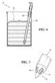
- FIG. 6is a cross-sectional view of the apparatus for storing and dispensing liquid from a liquid retaining bag depicted in FIG. 1 with the liquid retaining bag stored in the storage container and the liquid transport conduit located in one of several operating positions.
- FIG. 7is a fragmentary perspective view of the spiked end of the liquid transport conduit.
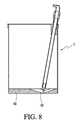
- FIG. 8is a cross-sectional view of an alternative apparatus for storing and dispensing liquid from a liquid retaining bag.
- storage and liquid dispensing unit Astores and dispenses liquid from a liquid retaining bag B.
- Liquid retaining bag Bis preferably formed from a collapsible material such that as liquid is dispensed from liquid retaining bag B, the bag B collapses.
- the liquid retained by bag Bis water.
- any suitable liquidmay retained by liquid retaining bag B.
- Storage and liquid dispensing unit Ais preferably used with a bottom loaded water cooler.
- storage and liquid dispensing unit A housing liquid retaining bag Bmay be used with the bottom loaded water cooler disclosed in U.S. Pat.
- storage and liquid dispensing unit A housing liquid retaining bag Bmay be positioned where water bottle E is disposed in FIG. 2 of U.S. Pat. No. 8,887,955.
- a shell of a bottom loaded water coolermay conceal storage and liquid dispensing unit A housing liquid retaining bag B.
- the shellmay include a removable portion that allows one to readily gain access to storage and liquid dispensing unit A and liquid retaining bag B
- Storage and liquid dispensing unit Aincludes a liquid transport assembly C. End 2 of connector 4 of liquid transport assembly C can be connected to the lower end 40 of riser tube 34 of the liquid dispenser disclosed in U.S. Pat. No. 8,887,955. Liquid can be dispensed from bag B in the same manner that liquid is dispensed from bottle E of U.S. Pat. No. 8,887,955.
- Liquid transport assembly Cfurther includes a dip tube 6 preferably having a single hollow cavity 8 extending from an upper open end 10 and a lower open end 12 .
- a spike 14 having a hollow internal cavity 16extends into lower open end 12 .
- spike 14includes one or more openings 15 .
- the openings 15can be uniformly spaced around the circumference of the tip of spike 14 .
- the number and spacing of openings 15can be readily varied as desired.
- spike 14is fixed to dip tube 6 such that liquid cannot pass between the outer cylindrical wall 18 of spike 14 and the internal cylindrical wall 20 of dip tube 6 .
- Any suitable meanscan be used to fix spike 14 to dip tube 6 .
- spike 14 and dip tube 6can be formed as a single piece.
- spike 14can be configured such that it seats on and surrounds the lower end 12 of dip tube 6 .
- Upper end of dip tube 6extends into and is sealingly connected to lower end 22 of connector 4 .
- Storage and liquid dispensing unit Aincludes a storage container 24 having a base 26 , a cylindrical wall 28 and a skirt 30 .
- Skirt 30surrounds and seats on the uppermost portion of wall 28 .
- Skirt 30can be fixed to wall 28 such that it cannot be removed from wall 28 by any suitable means including but not limited to glues, adhesives and/or fasteners.
- skirt 30can be removably connected to wall 28 by any suitable means including but not limited to a force or friction fit.
- skirt 30 and wall 28can be formed as a single piece.
- Base 26is preferably sealingly connected to the lower portion of wall 28 . This connection can be formed by any suitable means. Alternatively, base 26 and wall 28 can be formed as a single piece. Base 26 preferably includes a recess 32 for receiving the bottom of bag B.
- skirt 30includes a guide and retaining member 34 .
- guide and retaining member 34includes a cylindrical and inclined passageway 36 .
- a longitudinal axis passing through the center of passageway 36forms an acute angle with a vertical plane and or axis passing though the center of base 26 and the center of bag B.
- Passageway 36can be sized relative to dip tube 6 , such that dip tube 6 can be held in place (see FIG. 5 ) by guide and retaining member 34 when no force is applied to dip tube 6 and when a force is applied to dip tube 6 , dip tube 6 can move through passageway 36 to an operating position shown in FIG. 6 . Referring to FIGS.
- lower portion 38 of guide and retaining member 34is spaced from downwardly extending lip 40 of skirt 30 such that upper portion of wall 28 can extend into the spaced formed between downwardly extending lip 40 of skirt 30 and lower portion 38 .
- skirt 30 including member 34 and wall 28can be formed as a single piece.
- guide and retaining member 34occupies a very small portion of the area of the upper opening of storage container 24 . This allows the liquid retaining bag B to be readily removed from storage container 24 and replaced with a new and fully filled liquid retaining bag B without removing skirt 30 . Further, as seen in FIG. 5 , the liquid transport assembly C can be held in a raised position to allow for removal and replacement of the liquid retaining bag B. As seen in FIG. 6 , guide and retaining member 34 guide dip tube 6 such that spike 14 punctures bag B adjacent a sidewall 50 of bag B removed from a center portion of bag B.
- storage container 24including but not limited to the number of walls can be readily varied as desired.
- FIG. 8an alternative form of storage and liquid dispensing unit D is illustrated in one of many possible configurations.
- Storage and liquid dispensing unit Dis similar to liquid storage and liquid dispensing unit A and, therefore, only the differences will be described hereinafter.
- base 50 of storage and liquid dispensing unit Dincludes a well-like depression 52 configured to minimize the residual water in the liquid retaining bag.
Landscapes
- Packages (AREA)
- Devices For Dispensing Beverages (AREA)
Abstract
Description
Claims (20)
Priority Applications (7)
| Application Number | Priority Date | Filing Date | Title |
|---|---|---|---|
| US14/714,456US9714164B2 (en) | 2015-05-18 | 2015-05-18 | Apparatus for storing and dispensing liquid from a liquid retaining bag |
| MYPI2017704325AMY184787A (en) | 2015-05-18 | 2016-05-02 | An apparatus for storing and dispensing liquid from a liquid retaining bag |
| PCT/IB2016/052481WO2016185307A1 (en) | 2015-05-18 | 2016-05-02 | An apparatus for storing and dispensing liquid from a liquid retaining bag |
| AU2016264985AAU2016264985B2 (en) | 2015-05-18 | 2016-05-02 | An apparatus for storing and dispensing liquid from a liquid retaining bag |
| KR1020177033066AKR20180009743A (en) | 2015-05-18 | 2016-05-02 | Apparatus for storing and dispensing liquid from a liquid retaining bag |
| CN201680028321.XACN107810163B (en) | 2015-05-18 | 2016-05-02 | Device for storing and dispensing liquid from a liquid holding bag |
| EP16721500.3AEP3297947B1 (en) | 2015-05-18 | 2016-05-02 | An apparatus for storing and dispensing liquid from a liquid retaining bag |
Applications Claiming Priority (1)
| Application Number | Priority Date | Filing Date | Title |
|---|---|---|---|
| US14/714,456US9714164B2 (en) | 2015-05-18 | 2015-05-18 | Apparatus for storing and dispensing liquid from a liquid retaining bag |
Publications (2)
| Publication Number | Publication Date |
|---|---|
| US20160340168A1 US20160340168A1 (en) | 2016-11-24 |
| US9714164B2true US9714164B2 (en) | 2017-07-25 |
Family
ID=55953333
Family Applications (1)
| Application Number | Title | Priority Date | Filing Date |
|---|---|---|---|
| US14/714,456Expired - Fee RelatedUS9714164B2 (en) | 2015-05-18 | 2015-05-18 | Apparatus for storing and dispensing liquid from a liquid retaining bag |
Country Status (7)
| Country | Link |
|---|---|
| US (1) | US9714164B2 (en) |
| EP (1) | EP3297947B1 (en) |
| KR (1) | KR20180009743A (en) |
| CN (1) | CN107810163B (en) |
| AU (1) | AU2016264985B2 (en) |
| MY (1) | MY184787A (en) |
| WO (1) | WO2016185307A1 (en) |
Citations (38)
| Publication number | Priority date | Publication date | Assignee | Title |
|---|---|---|---|---|
| DE390369C (en) | 1921-10-23 | 1924-02-18 | Anton Franz Jung | Device for opening and pulling off the contents of metal containers |
| DE1293052B (en) | 1965-12-03 | 1969-04-17 | Flake Ice Machines Inc | Removal device for beverage container |
| US4058121A (en) | 1976-06-29 | 1977-11-15 | American Hospital Supply Corporation | Vented needle for medical liquids |
| GB2046226A (en) | 1979-03-09 | 1980-11-12 | Gabr S Z M | Dispensing of packaged liquids |
| US4265372A (en) | 1979-03-30 | 1981-05-05 | Lawrence Wainberg | Container and dispenser-cutter unit combination for containing and holding detachable flexible form-fill-seal plastic pouches |
| US4484697A (en)* | 1980-08-27 | 1984-11-27 | Shasta Beverages, Inc. | Method and apparatus for dispensing liquid |
| EP0141433A1 (en) | 1983-08-11 | 1985-05-15 | Douwe Egberts Koninklijke Tabaksfabriek- Koffiebranderijen-Theehandel N.V. | Container holder for post mix dispenser |
| US4527716A (en) | 1983-05-13 | 1985-07-09 | Cargill, Incorporated | Apparatus for dispensing material from a bag |
| WO1987005208A1 (en) | 1986-02-26 | 1987-09-11 | Broden Bengt Inge | A device for use in the handling of body fluids |
| US4997429A (en) | 1988-12-28 | 1991-03-05 | Sherwood Medical Company | Enteral bottle cap with vent valve |
| WO1992019528A1 (en) | 1991-04-29 | 1992-11-12 | Du Pont Canada Inc. | Reusable pouch fitment |
| US5392968A (en) | 1993-06-14 | 1995-02-28 | Dark; Richard C. G. | Dispensing closure and method |
| US5553748A (en)* | 1992-11-27 | 1996-09-10 | Battle; John R. | Refillable liquid dispenser |
| US5881692A (en) | 1996-09-27 | 1999-03-16 | Outboard Marine Corporation | Ventless fluid reservoir |
| US5975359A (en)* | 1995-12-27 | 1999-11-02 | International Sanitary Ware Manufacturing Cy, S.A. | Needle engaging soap bag |
| US6098844A (en) | 1998-01-23 | 2000-08-08 | Kenneth Nicolle | Water dispensing system |
| US6139534A (en) | 2000-01-24 | 2000-10-31 | Bracco Diagnostics, Inc. | Vial access adapter |
| US6161728A (en) | 1999-08-18 | 2000-12-19 | Dark; Richard C. G. | Barrier piercing dispensing closure |
| US6269976B1 (en) | 2000-08-17 | 2001-08-07 | Saint-Gobain Calmar Inc. | Vial access spike adapter for pump sprayer |
| US6398073B1 (en) | 2000-07-24 | 2002-06-04 | Bag O Water Limited | Fluid dispensing system with collapsible container |
| US6832994B2 (en) | 2000-01-24 | 2004-12-21 | Bracco Diagnostics Inc. | Table top drug dispensing vial access adapter |
| US20050121464A1 (en)* | 2003-10-23 | 2005-06-09 | Don Miller | Container adapted to hold and dispense bagged fluids |
| US20060032864A1 (en)* | 2004-08-16 | 2006-02-16 | Jung Suk D | Water dispenser |
| US7165700B2 (en) | 2003-08-25 | 2007-01-23 | Henry Macler | Portable water cooler for use with bagged fluids and bagged fluids for use therewith |
| US7168599B1 (en)* | 2004-03-16 | 2007-01-30 | Richard Criswell | Water-handling system |
| US20070032775A1 (en) | 2000-01-24 | 2007-02-08 | Bracco Diagnostics, Inc. | Tabletop drug dispensing vial access adapter |
| WO2007081208A1 (en) | 2006-01-10 | 2007-07-19 | 4Sight Innovation B.V. | Device for tapping a drink from a container such as a can |
| US7331487B2 (en) | 2003-09-12 | 2008-02-19 | Ammm Patent Holdings, Llc | Office water cooler adapter for use with bagged fluids |
| EP2017195A1 (en) | 2006-05-08 | 2009-01-21 | Surpass Industry Co., Ltd. | Connector structure |
| US8177096B2 (en) | 2007-03-27 | 2012-05-15 | International Packaging Innovations, Llc | Bag cooler employing a multi-spike adapter and converter |
| US20130053815A1 (en) | 2011-08-23 | 2013-02-28 | Allergan, Inc. | High recovery vial adaptor |
| US20130048681A1 (en)* | 2011-08-29 | 2013-02-28 | Philip A. Walton | Apparatus for dispensing a liquid from a liquid storage container |
| US8672155B2 (en) | 2006-08-01 | 2014-03-18 | Fresenius Kabi Deutschland Gmbh | Closure cap for a container filled with medicinal fluid, and container having a closure cap |
| US8770441B2 (en) | 2007-03-27 | 2014-07-08 | International Packaging Innovations, Llc | Multiple channel single spike for a liquid dispensing system |
| WO2014110242A1 (en) | 2013-01-10 | 2014-07-17 | International Packaging Innovations, Llc | Multiple channel single spike for a liquid dispensing system |
| US9101936B2 (en)* | 2007-04-27 | 2015-08-11 | Radiometer Medical Aps | Sealed oxygen reference fluid containing bag |
| US20150284235A1 (en)* | 2012-10-10 | 2015-10-08 | Raymond Wilson Blackburn | Fluid dispensor with isolation membrane |
| US9527639B2 (en) | 2015-01-26 | 2016-12-27 | Cardomon International Limited | Dip tube insertion member for facilitating insertion of a dip tube into a container without removing the container cap |
Family Cites Families (2)
| Publication number | Priority date | Publication date | Assignee | Title |
|---|---|---|---|---|
| US20060175355A1 (en)* | 2005-02-09 | 2006-08-10 | Glucksman Dov Z | Beverage dispenser |
| CN101513946A (en)* | 2007-12-19 | 2009-08-26 | 罗吉多斯股份公司 | Dispensing device for dispensing a liquid product |
- 2015
- 2015-05-18USUS14/714,456patent/US9714164B2/ennot_activeExpired - Fee Related
- 2016
- 2016-05-02AUAU2016264985Apatent/AU2016264985B2/ennot_activeCeased
- 2016-05-02EPEP16721500.3Apatent/EP3297947B1/enactiveActive
- 2016-05-02CNCN201680028321.XApatent/CN107810163B/ennot_activeExpired - Fee Related
- 2016-05-02MYMYPI2017704325Apatent/MY184787A/enunknown
- 2016-05-02WOPCT/IB2016/052481patent/WO2016185307A1/ennot_activeCeased
- 2016-05-02KRKR1020177033066Apatent/KR20180009743A/ennot_activeCeased
Patent Citations (42)
| Publication number | Priority date | Publication date | Assignee | Title |
|---|---|---|---|---|
| DE390369C (en) | 1921-10-23 | 1924-02-18 | Anton Franz Jung | Device for opening and pulling off the contents of metal containers |
| DE1293052B (en) | 1965-12-03 | 1969-04-17 | Flake Ice Machines Inc | Removal device for beverage container |
| US4058121A (en) | 1976-06-29 | 1977-11-15 | American Hospital Supply Corporation | Vented needle for medical liquids |
| GB2046226A (en) | 1979-03-09 | 1980-11-12 | Gabr S Z M | Dispensing of packaged liquids |
| US4265372A (en) | 1979-03-30 | 1981-05-05 | Lawrence Wainberg | Container and dispenser-cutter unit combination for containing and holding detachable flexible form-fill-seal plastic pouches |
| US4484697A (en)* | 1980-08-27 | 1984-11-27 | Shasta Beverages, Inc. | Method and apparatus for dispensing liquid |
| US4527716A (en) | 1983-05-13 | 1985-07-09 | Cargill, Incorporated | Apparatus for dispensing material from a bag |
| EP0141433A1 (en) | 1983-08-11 | 1985-05-15 | Douwe Egberts Koninklijke Tabaksfabriek- Koffiebranderijen-Theehandel N.V. | Container holder for post mix dispenser |
| WO1987005208A1 (en) | 1986-02-26 | 1987-09-11 | Broden Bengt Inge | A device for use in the handling of body fluids |
| US4997429A (en) | 1988-12-28 | 1991-03-05 | Sherwood Medical Company | Enteral bottle cap with vent valve |
| WO1992019528A1 (en) | 1991-04-29 | 1992-11-12 | Du Pont Canada Inc. | Reusable pouch fitment |
| US5553748A (en)* | 1992-11-27 | 1996-09-10 | Battle; John R. | Refillable liquid dispenser |
| US5392968A (en) | 1993-06-14 | 1995-02-28 | Dark; Richard C. G. | Dispensing closure and method |
| US5975359A (en)* | 1995-12-27 | 1999-11-02 | International Sanitary Ware Manufacturing Cy, S.A. | Needle engaging soap bag |
| US5881692A (en) | 1996-09-27 | 1999-03-16 | Outboard Marine Corporation | Ventless fluid reservoir |
| US6098844A (en) | 1998-01-23 | 2000-08-08 | Kenneth Nicolle | Water dispensing system |
| US6161728A (en) | 1999-08-18 | 2000-12-19 | Dark; Richard C. G. | Barrier piercing dispensing closure |
| US6832994B2 (en) | 2000-01-24 | 2004-12-21 | Bracco Diagnostics Inc. | Table top drug dispensing vial access adapter |
| US6139534A (en) | 2000-01-24 | 2000-10-31 | Bracco Diagnostics, Inc. | Vial access adapter |
| US20070032775A1 (en) | 2000-01-24 | 2007-02-08 | Bracco Diagnostics, Inc. | Tabletop drug dispensing vial access adapter |
| US6398073B1 (en) | 2000-07-24 | 2002-06-04 | Bag O Water Limited | Fluid dispensing system with collapsible container |
| US6269976B1 (en) | 2000-08-17 | 2001-08-07 | Saint-Gobain Calmar Inc. | Vial access spike adapter for pump sprayer |
| US7762429B2 (en) | 2003-08-25 | 2010-07-27 | International Packaging Innovations, Llc | Portable water cooler for use with bagged fluids and bagged fluids for use therewith |
| US7165700B2 (en) | 2003-08-25 | 2007-01-23 | Henry Macler | Portable water cooler for use with bagged fluids and bagged fluids for use therewith |
| US7331487B2 (en) | 2003-09-12 | 2008-02-19 | Ammm Patent Holdings, Llc | Office water cooler adapter for use with bagged fluids |
| US20050121464A1 (en)* | 2003-10-23 | 2005-06-09 | Don Miller | Container adapted to hold and dispense bagged fluids |
| US7188749B2 (en) | 2003-10-23 | 2007-03-13 | Ammm Patent Holdings, Llc | Container adapted to hold and dispense bagged fluids |
| US7168599B1 (en)* | 2004-03-16 | 2007-01-30 | Richard Criswell | Water-handling system |
| US20060032864A1 (en)* | 2004-08-16 | 2006-02-16 | Jung Suk D | Water dispenser |
| WO2007081208A1 (en) | 2006-01-10 | 2007-07-19 | 4Sight Innovation B.V. | Device for tapping a drink from a container such as a can |
| EP2017195A1 (en) | 2006-05-08 | 2009-01-21 | Surpass Industry Co., Ltd. | Connector structure |
| US8672155B2 (en) | 2006-08-01 | 2014-03-18 | Fresenius Kabi Deutschland Gmbh | Closure cap for a container filled with medicinal fluid, and container having a closure cap |
| US8464906B2 (en) | 2007-03-27 | 2013-06-18 | International Packaging Innovations, Llc | Bag cooler employing a multi-spike adapter and converter |
| US8177096B2 (en) | 2007-03-27 | 2012-05-15 | International Packaging Innovations, Llc | Bag cooler employing a multi-spike adapter and converter |
| US8770441B2 (en) | 2007-03-27 | 2014-07-08 | International Packaging Innovations, Llc | Multiple channel single spike for a liquid dispensing system |
| US9101936B2 (en)* | 2007-04-27 | 2015-08-11 | Radiometer Medical Aps | Sealed oxygen reference fluid containing bag |
| US20130053815A1 (en) | 2011-08-23 | 2013-02-28 | Allergan, Inc. | High recovery vial adaptor |
| US20130048681A1 (en)* | 2011-08-29 | 2013-02-28 | Philip A. Walton | Apparatus for dispensing a liquid from a liquid storage container |
| US8887955B2 (en) | 2011-08-29 | 2014-11-18 | Cardomon International Limited | Apparatus for dispensing a liquid from a liquid storage container |
| US20150284235A1 (en)* | 2012-10-10 | 2015-10-08 | Raymond Wilson Blackburn | Fluid dispensor with isolation membrane |
| WO2014110242A1 (en) | 2013-01-10 | 2014-07-17 | International Packaging Innovations, Llc | Multiple channel single spike for a liquid dispensing system |
| US9527639B2 (en) | 2015-01-26 | 2016-12-27 | Cardomon International Limited | Dip tube insertion member for facilitating insertion of a dip tube into a container without removing the container cap |
Non-Patent Citations (1)
| Title |
|---|
| International Search Report and Written Opinion, Jun. 30, 2016 issued in International Application No. PCT/IB2016/052481, 8 pages. |
Also Published As
| Publication number | Publication date |
|---|---|
| WO2016185307A1 (en) | 2016-11-24 |
| US20160340168A1 (en) | 2016-11-24 |
| CN107810163B (en) | 2020-10-20 |
| CN107810163A (en) | 2018-03-16 |
| AU2016264985A1 (en) | 2017-11-16 |
| AU2016264985B2 (en) | 2021-02-25 |
| EP3297947B1 (en) | 2021-04-14 |
| MY184787A (en) | 2021-04-22 |
| KR20180009743A (en) | 2018-01-29 |
| EP3297947A1 (en) | 2018-03-28 |
Similar Documents
| Publication | Publication Date | Title |
|---|---|---|
| US8151838B2 (en) | Liquid dispensing system | |
| US7331486B2 (en) | Pump dispenser and cartridge | |
| US6032812A (en) | One-piece cap for liquid dispenser container | |
| RU2533721C2 (en) | Vessel for containment and dispensing of pressurised beverage | |
| US9527639B2 (en) | Dip tube insertion member for facilitating insertion of a dip tube into a container without removing the container cap | |
| US5431297A (en) | Pop-up straw for beverage containers | |
| EP0479938B1 (en) | A device for dispensing flowing substances | |
| US20170225937A1 (en) | Counter Water Bottle Dispenser | |
| US9580290B1 (en) | Counter water bottle dispenser | |
| US10273056B2 (en) | Fuel container system | |
| US20140144948A1 (en) | Self-Ventilating Container | |
| US9986851B2 (en) | Double ended cup dispenser | |
| US9714164B2 (en) | Apparatus for storing and dispensing liquid from a liquid retaining bag | |
| RU2401797C1 (en) | Jointing mechanism between container for drinks and drink distributing device with said mechanism, and drink distributing device with said mechanism | |
| US6607102B1 (en) | Rapid flow fitment | |
| US7156254B2 (en) | Blow molded drum | |
| US551540A (en) | Liquid-dispensing apparatus | |
| GB2430927A (en) | Bottle carrier combined with bottle opener | |
| US10059579B1 (en) | Liquid dispensing system | |
| US662168A (en) | Dispensing device for water-coolers. | |
| US358319A (en) | Edwaed c | |
| US531759A (en) | Charles abs | |
| JPH1111510A (en) | Instrument for liquid ejection | |
| JP2018154377A (en) | Carbonated drink server | |
| HK1245227B (en) | A dip tube insertion member for facilitating insertion of a dip tube into a container without removing the container cap |
Legal Events
| Date | Code | Title | Description |
|---|---|---|---|
| AS | Assignment | Owner name:CARDOMON INTERNATIONAL LIMITED, HONG KONG Free format text:ASSIGNMENT OF ASSIGNORS INTEREST;ASSIGNOR:WALTON, PHILIP;REEL/FRAME:042353/0893 Effective date:20170511 Owner name:CARDOMON INTERNATIONAL LIMITED, HONG KONG Free format text:ASSIGNMENT OF ASSIGNORS INTEREST;ASSIGNOR:PARTINGTON, FREDERICK;REEL/FRAME:042354/0272 Effective date:20170511 | |
| STCF | Information on status: patent grant | Free format text:PATENTED CASE | |
| MAFP | Maintenance fee payment | Free format text:PAYMENT OF MAINTENANCE FEE, 4TH YR, SMALL ENTITY (ORIGINAL EVENT CODE: M2551); ENTITY STATUS OF PATENT OWNER: SMALL ENTITY Year of fee payment:4 | |
| FEPP | Fee payment procedure | Free format text:MAINTENANCE FEE REMINDER MAILED (ORIGINAL EVENT CODE: REM.); ENTITY STATUS OF PATENT OWNER: SMALL ENTITY | |
| LAPS | Lapse for failure to pay maintenance fees | Free format text:PATENT EXPIRED FOR FAILURE TO PAY MAINTENANCE FEES (ORIGINAL EVENT CODE: EXP.); ENTITY STATUS OF PATENT OWNER: SMALL ENTITY | |
| STCH | Information on status: patent discontinuation | Free format text:PATENT EXPIRED DUE TO NONPAYMENT OF MAINTENANCE FEES UNDER 37 CFR 1.362 | |
| FP | Lapsed due to failure to pay maintenance fee | Effective date:20250725 |