US9713710B2 - Systems and methods for anesthetizing ear tissue - Google Patents
Systems and methods for anesthetizing ear tissueDownload PDFInfo
- Publication number
- US9713710B2 US9713710B2US13/798,635US201313798635AUS9713710B2US 9713710 B2US9713710 B2US 9713710B2US 201313798635 AUS201313798635 AUS 201313798635AUS 9713710 B2US9713710 B2US 9713710B2
- Authority
- US
- United States
- Prior art keywords
- earplug
- sealing element
- tube
- ear
- electrode
- Prior art date
- Legal status (The legal status is an assumption and is not a legal conclusion. Google has not performed a legal analysis and makes no representation as to the accuracy of the status listed.)
- Expired - Fee Related, expires
Links
Images


Classifications
- A—HUMAN NECESSITIES
- A61—MEDICAL OR VETERINARY SCIENCE; HYGIENE
- A61F—FILTERS IMPLANTABLE INTO BLOOD VESSELS; PROSTHESES; DEVICES PROVIDING PATENCY TO, OR PREVENTING COLLAPSING OF, TUBULAR STRUCTURES OF THE BODY, e.g. STENTS; ORTHOPAEDIC, NURSING OR CONTRACEPTIVE DEVICES; FOMENTATION; TREATMENT OR PROTECTION OF EYES OR EARS; BANDAGES, DRESSINGS OR ABSORBENT PADS; FIRST-AID KITS
- A61F11/00—Methods or devices for treatment of the ears or hearing sense; Non-electric hearing aids; Methods or devices for enabling ear patients to achieve auditory perception through physiological senses other than hearing sense; Protective devices for the ears, carried on the body or in the hand
- A—HUMAN NECESSITIES
- A61—MEDICAL OR VETERINARY SCIENCE; HYGIENE
- A61M—DEVICES FOR INTRODUCING MEDIA INTO, OR ONTO, THE BODY; DEVICES FOR TRANSDUCING BODY MEDIA OR FOR TAKING MEDIA FROM THE BODY; DEVICES FOR PRODUCING OR ENDING SLEEP OR STUPOR
- A61M31/00—Devices for introducing or retaining media, e.g. remedies, in cavities of the body
- A—HUMAN NECESSITIES
- A61—MEDICAL OR VETERINARY SCIENCE; HYGIENE
- A61F—FILTERS IMPLANTABLE INTO BLOOD VESSELS; PROSTHESES; DEVICES PROVIDING PATENCY TO, OR PREVENTING COLLAPSING OF, TUBULAR STRUCTURES OF THE BODY, e.g. STENTS; ORTHOPAEDIC, NURSING OR CONTRACEPTIVE DEVICES; FOMENTATION; TREATMENT OR PROTECTION OF EYES OR EARS; BANDAGES, DRESSINGS OR ABSORBENT PADS; FIRST-AID KITS
- A61F11/00—Methods or devices for treatment of the ears or hearing sense; Non-electric hearing aids; Methods or devices for enabling ear patients to achieve auditory perception through physiological senses other than hearing sense; Protective devices for the ears, carried on the body or in the hand
- A61F11/06—Protective devices for the ears
- A61F11/08—Protective devices for the ears internal, e.g. earplugs
- A61M1/0088—
- A—HUMAN NECESSITIES
- A61—MEDICAL OR VETERINARY SCIENCE; HYGIENE
- A61M—DEVICES FOR INTRODUCING MEDIA INTO, OR ONTO, THE BODY; DEVICES FOR TRANSDUCING BODY MEDIA OR FOR TAKING MEDIA FROM THE BODY; DEVICES FOR PRODUCING OR ENDING SLEEP OR STUPOR
- A61M1/00—Suction or pumping devices for medical purposes; Devices for carrying-off, for treatment of, or for carrying-over, body-liquids; Drainage systems
- A61M1/90—Negative pressure wound therapy devices, i.e. devices for applying suction to a wound to promote healing, e.g. including a vacuum dressing
- A61M1/96—Suction control thereof
- A61M1/964—Suction control thereof having venting means on or near the dressing
- A—HUMAN NECESSITIES
- A61—MEDICAL OR VETERINARY SCIENCE; HYGIENE
- A61N—ELECTROTHERAPY; MAGNETOTHERAPY; RADIATION THERAPY; ULTRASOUND THERAPY
- A61N1/00—Electrotherapy; Circuits therefor
- A61N1/18—Applying electric currents by contact electrodes
- A61N1/20—Applying electric currents by contact electrodes continuous direct currents
- A61N1/30—Apparatus for iontophoresis, i.e. transfer of media in ionic state by an electromotoric force into the body, or cataphoresis
- A61N1/303—Constructional details
- A61N1/306—Arrangements where at least part of the apparatus is introduced into the body
- A—HUMAN NECESSITIES
- A61—MEDICAL OR VETERINARY SCIENCE; HYGIENE
- A61M—DEVICES FOR INTRODUCING MEDIA INTO, OR ONTO, THE BODY; DEVICES FOR TRANSDUCING BODY MEDIA OR FOR TAKING MEDIA FROM THE BODY; DEVICES FOR PRODUCING OR ENDING SLEEP OR STUPOR
- A61M1/00—Suction or pumping devices for medical purposes; Devices for carrying-off, for treatment of, or for carrying-over, body-liquids; Drainage systems
- A61M1/90—Negative pressure wound therapy devices, i.e. devices for applying suction to a wound to promote healing, e.g. including a vacuum dressing
- A61M1/96—Suction control thereof
- A—HUMAN NECESSITIES
- A61—MEDICAL OR VETERINARY SCIENCE; HYGIENE
- A61M—DEVICES FOR INTRODUCING MEDIA INTO, OR ONTO, THE BODY; DEVICES FOR TRANSDUCING BODY MEDIA OR FOR TAKING MEDIA FROM THE BODY; DEVICES FOR PRODUCING OR ENDING SLEEP OR STUPOR
- A61M19/00—Local anaesthesia; Hypothermia
- A—HUMAN NECESSITIES
- A61—MEDICAL OR VETERINARY SCIENCE; HYGIENE
- A61M—DEVICES FOR INTRODUCING MEDIA INTO, OR ONTO, THE BODY; DEVICES FOR TRANSDUCING BODY MEDIA OR FOR TAKING MEDIA FROM THE BODY; DEVICES FOR PRODUCING OR ENDING SLEEP OR STUPOR
- A61M2205/00—General characteristics of the apparatus
- A61M2205/33—Controlling, regulating or measuring
- A61M2205/3331—Pressure; Flow
- A61M2205/3341—Pressure; Flow stabilising pressure or flow to avoid excessive variation
- A—HUMAN NECESSITIES
- A61—MEDICAL OR VETERINARY SCIENCE; HYGIENE
- A61M—DEVICES FOR INTRODUCING MEDIA INTO, OR ONTO, THE BODY; DEVICES FOR TRANSDUCING BODY MEDIA OR FOR TAKING MEDIA FROM THE BODY; DEVICES FOR PRODUCING OR ENDING SLEEP OR STUPOR
- A61M2210/00—Anatomical parts of the body
- A61M2210/06—Head
- A61M2210/0662—Ears
- A—HUMAN NECESSITIES
- A61—MEDICAL OR VETERINARY SCIENCE; HYGIENE
- A61N—ELECTROTHERAPY; MAGNETOTHERAPY; RADIATION THERAPY; ULTRASOUND THERAPY
- A61N1/00—Electrotherapy; Circuits therefor
- A61N1/02—Details
- A61N1/04—Electrodes
- A61N1/0404—Electrodes for external use
- A61N1/0408—Use-related aspects
- A61N1/0428—Specially adapted for iontophoresis, e.g. AC, DC or including drug reservoirs
- A61N1/0432—Anode and cathode
- A61N1/044—Shape of the electrode
- A—HUMAN NECESSITIES
- A61—MEDICAL OR VETERINARY SCIENCE; HYGIENE
- A61N—ELECTROTHERAPY; MAGNETOTHERAPY; RADIATION THERAPY; ULTRASOUND THERAPY
- A61N1/00—Electrotherapy; Circuits therefor
- A61N1/18—Applying electric currents by contact electrodes
- A61N1/32—Applying electric currents by contact electrodes alternating or intermittent currents
- A61N1/36—Applying electric currents by contact electrodes alternating or intermittent currents for stimulation
- A61N1/36014—External stimulators, e.g. with patch electrodes
- A61N1/36021—External stimulators, e.g. with patch electrodes for treatment of pain
Definitions
- the present inventionis related to iontophoretic drug delivery methods and systems.
- the present inventionis related to novel and advantageous iontophoretic drug delivery methods and systems for anesthetizing ear tissue.
- Iontophoresisis a method for delivering a drug across a biological membrane, such as the skin or, in the case of certain ear surgery procedures, the tympanic membrane (TM).
- TMtympanic membrane
- iontophoresisrepels ions of the drug, thus transporting them across the skin or other membrane.
- iontophoresisattempts have been made in the past to use iontophoresis to anesthetize (or “numb”) a TM before placing an ear tube across it to treat chronic ear infections.
- TM iontophoresisa drug solution is placed in an ear canal and current is applied to the solution via an electrode, thus transporting the anesthetizing drug across the TM.
- Prior iontophoresis devices and systemshave had limited success and often cannot be used in all patients.
- Prior devicesgenerally do not seal the drug solution in an ear canal, thus requiring a patient to recline and tilt his/her head during an iontophoresis procedure.
- the patientUsing currently available iontophoresis methods, the patient must remain relatively motionless in this reclined, head-tilted position for 5-15 minutes while the iontophoresis procedure provides adequate anesthesia to the TM, which can be especially difficult for children.
- using the currently available systemsit is only possible to anesthetize one ear at a time, thus making iontophoretic anesthesia of both TMs in a patient a relatively lengthy, uncomfortable process.
- Earplugssuch as the one described in Donaldson and other currently available earplugs, however, have a number of shortcomings. For example, most earplugs are designed to keep fluid out of the ear canal, rather than in the ear canal. Currently available and previously described earplugs generally do not conform adequately to the curved anatomy of the ear canal and thus to not form a good seal in the ear canals of at least some (and in some cases all) patients.
- earplugstypically allow fluid to leak out of the ear, which makes iontophoretic anesthesia delivery difficult if not impossible with the patient in an upright position.
- previously described earplug devices for use in iontophoresishave not addressed issues such as bubble formation in the iontophoretic drug solution, which bubbles may interfere with the contact between an iontophoretic electrode and the solution.
- an iontophoresis system for anesthetizing the tympanic membrane of an ear of a patientmay include an earplug, at least one flexible sealing element, and an electrode device.
- the earplugmay include an distal portion, an proximal portion, a tube connecting the distal and proximal portions, and a side vent located at the tube or the proximal portion.
- the tubemay have a relative stiffness that is less than that of the distal and proximal portions, the lower relative stiffness allowing the tube to conform to the curvature of an ear canal.
- the flexible sealing elementmay be coupled to the tube of the earplug and may be shaped to form a seal within the ear canal.
- the electrodemay include an electrode tip and an elongate shaft and may be slideably disposable within the tube of the earplug, wherein the electrode tip is sized to fit within the distal portion and slide within the tube.
- the earplugmay include a side vent in fluid communication with the tube for allowing venting of air and/or fluid from the tube.
- the distal portionmay be rigid relative to the tube.
- the distal portionmay include an o-ring which seals against the electrode tip of the electrode device in the advanced position.
- an outer diameter of the electrode tipmay be greater than an internal diameter of the o-ring, and the o-ring may be flexible to allow the electrode tip to pass into it to a seal.
- the proximal portionmay be rigid.
- the proximal portionmay include a luer fitting.
- the at least one flexible sealing elementmay be umbrella shaped, with an open end of the sealing element facing the proximal end of the earplug.
- the at least one flexible sealing elementmay include a distal sealing element and a proximal sealing element, and a diameter of the proximal sealing element may be larger than a diameter of the distal sealing element.
- each of the flexible sealing elementsmay be umbrella shaped, with an open end of each sealing element facing the proximal end of the earplug.
- the electrode devicemay be malleable.
- the electrode devicemay include a lumen.
- the systemmay include an ear hook connected with the proximal portion of the earplug, the ear hook including a curved member for engaging a portion of the ear and preventing dislodgement of the earplug after placement in the ear.
- the systemmay include an additional earplug and an additional electrode for use in iontophoretic substance delivery to the tympanic membrane of the other ear of the human or animal subject.
- the systemmay include a headset for coupling the earplug and the additional earplug while they are in the subject's ears.
- a system for use in iontophoretic substance delivery to the tympanic membrane of an ear of a human or animal subjectmay include an elongate, flexible tube with a proximal portion and a distal portion, a first flexible sealing element shaped like an umbrella to form a seal within the ear canal, a second flexible sealing element shaped like an umbrella to form a seal within the ear canal, a distal stiffening tube located within the distal portion of the elongate tube distal to the sealing member, a luer fitting coupled with the proximal portion of the tube and including a side vent in fluid communication with the main lumen of the tube, and an electrode device.
- the flexible tubemay include a main lumen extending therethrough.
- the distal portionmay include an inner lip at the distal end of the distal portion and a sealing member proximal to the inner lip.
- the elongate tubemay have sufficient flexibility to bend to conform to the shape of an ear canal.
- the first flexible sealing elementmay be integral to and disposed on an exterior of the elongate tube and being offset a distance from a distal most portion of the elongate tube.
- the second flexible sealing elementmay be integral to and disposed on the exterior of the elongate tube and proximal to the first sealing element.
- the distal stiffening tubemay prevent the distal portion of the elongate tube from bending.
- the electrode devicemay include an elongate shaft.
- the electrode tipmay have a diameter greater than that of the elongate shaft.
- the electrode devicemay be movable within the tube lumen of the earplug from a retracted position, in which fluid may pass around the electrode through the tube, to an advanced position, in which the electrode tip may fit within the distal portion of the elongate tube between the inner lip and the sealing member to form a fluid tight seal.
- a method of anesthetizing a tympanic membrane of an ear of a patient using iontophoresismay involve delivering an anesthetizing drug solution to an ear canal of the patient, inserting a iontophoresis device into the ear canal filled with anesthetizing drug solution, venting excess anesthetizing drug solution through the lumen while inserting and while the electrode is in the first position, moving the electrode from the first position to the second position, and activating the electrode in the second position.
- the iontophoresis devicemay include an electrode moveable from a first position to a second position inside a lumen. The first position of the iontophoresis device may vent the ear canal. The second position of the iontophoresis device may seal the ear canal.
- the methodmay further include verifying moving the electrode from the first position to the second position using auditory and/or tactile feedback.
- the methodmay include repeating the method for a second ear of the subject.
- a head of the subjectmay be positioned in a reclined, tilted position when delivering the drug solution to the ear canal and an upright position when activating the electrode.
- the methodmay include repeating the method for a second ear of the subject, coupling the earplugs with a headset coupled with the subject's head before or during activating.
- the methodmay include deforming the electrode to conform it to a shape of the ear canal.
- a method of anesthetizing a tympanic membrane of an ear of a patient using iontophoresismay include delivering an anesthetizing drug solution to an ear canal of the patient, inserting a iontophoresis device into an ear canal of the patient, and activating the electrode.
- the iontophoresis devicemay include an electrode inside a lumen. The iontophoresis device may seal the anesthetizing drug solution and simultaneously vents excess anesthetizing drug solution past the electrode and through a seal inside the lumen.
- the methodmay include repeating the method for a second ear of the patient.
- the patientmay be in a sideways position when delivering and an upright position when activating.
- the methodmay include deforming the electrode to conform to the shape of the ear canal.
- a kit for anesthetizing a tympanic membrane of an ear of a human or animal subject using iontophoresismay include an earplug and a controller.
- the earplugmay include a distal portion, a proximal portion, and a tube extending from the distal portion to the proximal portion, at least one flexible sealing element extending from an outer surface of the tube and disposed closer to the distal end than the proximal end, and an electrode device.
- the tubemay have a stiffness less than a stiffness of the proximal and distal portions of the earplug.
- the electrode devicemay include an elongate shaft, and an electrode tip having a diameter greater than that of the elongate shaft.
- the electrode devicemay be movable within the tube of the earplug from a retracted position, in which fluid can pass around the electrode through the tube, to an advanced position, in which the electrode tip contacts an inner surface of the tube to prevent fluid from flowing through the tube.
- the controllermay be electrically connectable to the electrode device.
- the kitmay include an additional earplug for the other ear of the subject, and an additional electrode device for the additional earplug.
- the controllermay connect to the electrode device and the additional electrode device.
- the kitmay include a headset for placing on the subject's head and holding the electrodes and earplugs.
- the kitmay include a sufficient amount of drug solution to provide iontophoretic anesthesia to the tympanic membranes of both ears of the subject.
- the kitmay include a drug delivery device for delivering the drug solution into the ear canals of the subject.
- FIG. 1Ashows a frontal view of an outer ear.
- FIG. 1Bshows a partial cross-sectional view of an outer, middle, and inner ear.
- FIGS. 2A-2Cshow cross-sectional views of a system for anesthetizing a tympanic membrane, according to various embodiments of the invention.
- FIG. 2Dshows a perspective view of a distal end of an earplug, according to one embodiment of the invention.
- FIG. 2Eshows a side view of an earplug, according to one embodiment of the invention.
- FIGS. 2F and 2Gshow side views of systems for anesthetizing a tympanic membrane, according to various embodiments of the invention.
- FIG. 2Hshows a system in use, according to one embodiment of the invention.
- FIGS. 3A-3Cshow partial cross-sectional views of a system for anesthetizing a tympanic membrane in use, according to various embodiments of the invention.
- FIG. 4shows a kit for anesthetizing a tympanic membrane, according to one embodiment of the invention.
- FIG. 5Ashows a frontal view of a flexible sealing element, according to one embodiment of the invention.
- FIG. 5Bshows a side view of a flexible sealing element, according to one embodiment of the invention.
- FIG. 5Cshows a frontal view of a flexible sealing element, according to one embodiment of the invention.
- FIG. 5Dshows a side view of a flexible sealing element, according to one embodiment of the invention.
- FIG. 5Eshows a perspective view of a flexible sealing element, according to one embodiment of the invention.
- FIG. 5Fshows a front view of a flexible sealing element, according to one embodiment of the invention.
- FIG. 6Ashows a front view of an earplug including an ear hook, according to one embodiment of the invention.
- FIG. 6Bshows a front view of an earplug including an ear hook, according to one embodiment of the invention.
- FIG. 6Cshows a facing view of an earplug including an ear hook in use, according to one embodiment of the invention.
- FIG. 6Dshows a side view of a integrated ear bud, according to one embodiment of the invention
- FIGS. 6E and 6Fshow facing views of integrated ear buds in use, according to various embodiments of the invention.
- FIG. 7Ashows a perspective view of an earplug, according to one embodiment of the invention.
- FIG. 7Bshows a perspective view of an extended portion for use in an earplug, according to one embodiment of the invention.
- FIG. 7Cshows a cross-sectional view of an extended portion for use in an earplug, according to one embodiment of the invention.
- FIGS. 7D-7Ishow perspective views of extended portions for use in an earplug, according to various embodiments of the invention.
- FIG. 7Jshows an exploded view of an extended portion for use in an earplug, according to one embodiment of the invention.
- FIG. 8Ashows a side view of an expandable earplug, according to one embodiment of the invention.
- FIG. 8Bshows a side view of an expandable earplug in use, according to one embodiment of the invention.
- FIG. 9Ashows a cross-sectional view of a foam plug device, according to one embodiment of the invention.
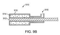
- FIG. 9Bshows a cross-sectional view of a foam balloon device, according to an embodiment of the invention.
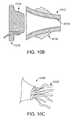
- FIG. 10Ashows a cross-sectional view of speculum port, according to an embodiment of the invention.
- FIG. 10Bshows a cross-sectional view an alternative distal port, according to one embodiment of the invention.
- FIG. 10Cshows a perspective view of an alternative distal port, according to one embodiment of the invention
- FIGS. 10D and 10Eshow a speculum port in use, according to one embodiment of the invention.
- FIGS. 10F through 10Hshow a speculum port in use, according to one embodiment of the invention.
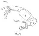
- FIGS. 11 and 12illustrate simplified support structures that are worn on a patient's head and support an iontophoresis system, according to various embodiments of the invention.
- FIG. 1Ashows a view of an outer ear.
- the outer earincludes a major element known as the auricle or pinna 100 .
- the outer earserves as a funnel for directing sounds into the internal portions of the ear.
- the major physical features of the earinclude the lobule 102 , concha 104 , anthelix 106 , helix 108 , scapha 110 , triangular fossa 112 , external acoustic meatus 114 , tragus 116 , and antitragus 118 .
- FIG. 1Bshows a cross-section of the inner and outer portions of the ear.
- the pinna 100is shown connected to the external auditory meatus 118 , or ear canal.
- the ear canal 118is shown as a relatively straight passage, but is often a more curved, tortuous passageway.
- the ear canal 118is connected to the middle ear 120 , which includes the ear drum 122 .
- the middle ear 120in turn is connected to the internal ear 124 .
- the ear drum 122normally has a pocket of air behind an outer portion called the tympanic membrane. When the middle ear 120 becomes infected, fluid swells inside the ear drum 122 . Fluid expansion causes extreme pain to one with a middle ear infection.
- Middle ear infectionsare common in young children. Suffering may be alleviated by puncturing the tympanic membrane to evacuate the fluid, a treatment known as tympanocentesis.
- the patientmay undergo general anesthesia prior to a tympanocentesis procedure, but this is not preferred due to cost and health concerns.
- the tympanic membranecan be locally anesthetized using iontophoretic drug delivery. Thus the patient may be treated while awake.
- Devices and methods for locally anesthetizing the tympanic membraneare disclosed in co-assigned patent applications U.S. Ser. No. 11/962,073 and U.S. Ser. No. 11/749,729, the entireties of which are incorporated by reference herein.
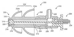
- FIG. 2Ashows an iontophoresis system 200 for anesthetizing a tympanic membrane, according to one embodiment of the invention.
- the system 200includes an earplug 202 and an electrode device 206 .
- the earplug 202may include a flexible sealing element 204 , a distal portion 208 , a proximal portion 210 , and a tube 212 connecting both.
- the tube 212is relatively more flexible, in terms of resistance to bending, than the distal portion 208 and proximal portion 210 . This is particularly advantageous because the ear canal often is a tortuous passage, which requires that the distal portion 208 and proximal portion 210 to be placed at opposite ends of the tortuous passage.
- the earplug 202will preferably bend and match the form of the tortuous passage without blocking the tube 212 .
- the earplug 202may be pre-bent or pre-formed in a preferred shape to match a tortuous passage of an ear canal.
- the earplug 202can be formed from a flexible polymer material, such as silicone.
- the distal portion 208can include a rigid member 214 .
- the rigid member 214can generally be cylindrical or tube shaped and include an inner lip 216 that prevents the electrode device from exiting the distal portion 208 .
- the rigid member 214can be constructed from a metal or polymer which adds structural integrity to the distal portion 208 .
- the rigid member 214provides the distal portion 208 to have a greater stiffness than the tube 212 , such that the distal portion 208 will maintain shape when passed through a tortuous passage.
- the rigid member 214can be bonded or molded into the distal portion 208 Alternatively, the rigid member 214 is integral to the distal portion 208 as a portion of wall thickness which is greater than the wall thickness of the tube 212 .
- the distal portion 208can also include an o-ring 218 .
- the o-ring 218fluidly seals the electrode device 206 inside the distal portion 208 .
- the o-ringcan be bonded or molded into the distal portion 208 , or alternatively be integrally formed between the distal portion 208 and the tube 212 .
- the o-ring 218can be designed to allow fluid to pass when experiencing a higher than atmosphere pressure load, e.g. the pressure which occurs from inserting the system 200 into a fluid filled ear.
- the o-ring 218can be designed as a duck-bill seal which opens into the proximal direction. It has been found in testing that 2.2 cm of H2O is a good value for threshold o-ring pressure relief.
- the proximal portion 210may be stiffer than the tube 212 such that the shape of the proximal portion 210 will be maintained when being inserted into a tortuous passage.
- the proximal portion 210can include a side vent 220 .
- the side vent 220functions to vent excess fluid out of the ear, which vents from the proximal portion 208 and through the tube 212 .
- the side vent 220may be located about the tube 212 .
- the proximal portion 210may include a luer fitting with a fluid tight fitting 222 to interface with the electrode device 206 , as shown.
- the proximal portionmay include a barbed portion 222 to interface with the tube 212 .
- the proximal portion 210may be integrally formed into the tube 212 , and maintain rigidity through molded stiffening inserts or by use of thick wall sections.
- the flexible sealing elements 204are used to form a fluid tight seal between the system 200 and the ear canal.
- the flexible sealing elements 204are generally flexible and deform and conform to the shape of an ear canal to form a fluid tight seal.
- Two flexible sealing elements 204are shown, however only one is required and more than two may be used.
- the first sealing element 204 amay be oval-umbrella shaped and integrally formed into the tube 212 and distal portion 208 , as shown.
- the flexible sealing elements 204may be pyramidal (three-sided) or triangular in shape. It has been found that the ear canal often has an oval or triangular cross-section.
- An offset 226 between the first flexible sealing element 204 a and the distal most portion of the system 200is preferred.
- the offset 226provides extra volume inside the ear for air bubbles to reside, thus preventing air bubbles from blocking the distal portion 208 .
- the second sealing element 204 bmay be larger than the first sealing element and integrally formed into the tube 212 , as shown.
- the flexible sealing elements 204can include adhesive elements to promote a fluid tight seal between the surface of the sealing elements 204 and the ear canal.
- an adhesive layercan be used on the external (i.e., canal facing) surfaces of the first sealing element 204 a and/or the second sealing element 204 b .
- the adhesive layercan be covered by a backing tape, which can be removed prior to insertion into the ear canal.
- a variety of adhesivescan be used, for example, a temperature dependent adhesive which is only mildly tacky at room temperature and becomes extremely tacky after insertion through heating by the ear canal. A temperature dependent adhesive may allow for placement and replacement in the complex anatomy of the ear to minimize patient discomfort.
- the earplug 202can be cooled by a cool compress to reduce tackiness and allow removal of the earplug 202 .
- adhesive elementsinclude the Eakin Cohesive® seal manufactured by CovaTec, Inc., and the Pre-Po® drape manufactured by Landec Labs, Inc.
- a temperature dependent adhesivewhich is extremely tacky at body temperature and becomes mildly tacky when heated to a temperature above body temperature can be used.
- heatcan be applied by a warm compress to reduce tackiness and allow removal of the earplug 202 .
- the electrode device 206includes an electrode tip 228 , an elongate shaft 230 , and a proximal connector 232 .
- the electrode tip 228may be cylindrically shaped to match the interior portion of the distal portion 208 .
- the electrode tip 228is generally shaped to form a seal within the distal portion 208 between the inner lip 216 and the o-ring 218 .
- the electrode tip 228is also sized to be slideably disposable within the tube 212 .
- the electrode tip 228is preferably constructed from silver (99.9% pure). It has been found that a pure silver electrode tip 228 , which may include an oxidized layer on the electrode tip 228 , aids in the iontophoresis procedure.
- Prior devicesutilized stainless steel or gold electrodes which have the tendency to cause electrolysis of an iontophoresis fluid, for example lidocaine, which in turn lowers the pH value and causes discomfort.
- the silver electroderelatively reduces electrolysis and prevents thus discomfort.
- the electrode tip 228may include a silver coating over a different metal such as stainless steel.
- the electrode tip 228is shown as a cylindrical shaped metal mass, however in alternative embodiments the electrode tip 228 can have different configurations to increase surface area and promote iontophoresis.
- a plurality of silver wires configured similarly to a brushcan be used.
- a plurality of concentric hypotubes with staggered diameterscan be used.
- a silver mesh mass configured similarly to steel woolcan be used.
- a molded polymer matrix plug with a relatively large surface area (e.g., sponge like) and a gold or silver plating or depositioncan be used.
- a metal-coated woven fabriccan be used, with or without an outer insulator depending on size.
- a cylindrical body with an internal and distally exposed honeycombcan be used.
- a silver foil coilcan be used.
- a recessed plug sized (i.e., smaller diameter) such that the plug has exposed sidescan be used.
- the elongate shaft 230can be used as the electrode, either as a tube or wire, and using a proximal seal in the tube 212 .
- a mass with a plurality of petals or branchese.g., flower shaped which are integrated into the surface of a flexible sealing element 204 can be used.
- a soft flexible bagwith an insulative outer surface and a silver coated inner surface, extending distally from the distal portion 208 can be used.
- one or more cavities, which include metal coated surfaces, in the distal portion 208may be used.
- the electrode tip 228can include holes and/or a textured surface (e.g., crosshatched, etched, sandblasted) to increase surface area.
- the electrode tip 228can include multiple metal types with one metal being a sacrificial anode (e.g., zinc).
- a conveyor systeme.g., a metal coated flexible belt
- the tube 212can include wiping elements which clean the surface of an electrode when turned, in order to supply a fresh electrode surface throughout the procedure.
- the electrode tip 228can include a protective coating to help prevent corrosion.
- the electrode tip 228may be attached to the elongate shaft 230 by soldering or welding.
- the elongate shaft 230may be constructed from the same materials as the electrode tip 228 .
- the elongate shaft 230may also include a lumen to allow the passage of fluid.
- the elongate shaft 230is preferably malleable to allow a user to pre-bend the elongate shaft before inserting the system 200 into an ear canal.
- the earplug 202may also be placed prior to the electrode device 206 , and thus the electrode device 206 may be shaped to conform to the pre-inserted and deformed earplug 202 .
- the proximal connector 232is shaped to fluidly seal with the proximal portion 210 .
- the proximal connector 232is further electrically connected to a wire 234 to provide energy to the electrode device 206 .
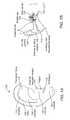
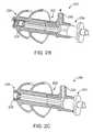
- FIG. 2Bshows the iontophoresis system 200 in a first position, according to one embodiment of the invention.
- the electrode device 206is shown with the electrode tip 228 in a proximal position inside the tube 212 .
- the distal portion 208is in fluid communication with the tube 212 .
- fluidmay pass through the distal portion 208 and out through the vent 220 , as shown by the directional arrow.
- FIG. 2Cshows the iontophoresis system 200 in a second position, according to one embodiment of the invention.
- the electrode device 206is shown with the electrode tip in a distal position within the distal portion 208 .
- the electrode device 206may be forcibly passed by the o-ring 218 which may cause an audible ‘snap’.
- the electrode device 206may be moved from the first position to the second position with an audible confirmation.
- the open distal position 208is closed and is no longer in fluid communication with the tube 212 .
- the o-ring 218may allow fluid to pass through when fluid pressures inside the ear canal exceed a threshold.
- FIG. 2Dshows an alternative embodiment of the iontophoresis system 200 .
- the offset portion 226 and distal portion 208each include a plurality of aligned holes 236 which are placed proximately behind the inner lip 216 .
- Four holes 236are shown, however, more or fewer holes may be used in alternative embodiments.
- the holes 236may have any of a number of suitable sizes, for example in one embodiment they may have diameters of about 0.025 inches each.
- the holes 236can reduce trapped volume of the drug solution and allow more surface area of the electrode tip 228 to be exposed, which in turn can decrease the voltage requirement for an iontophoresis procedure.
- An iontophoresis proceduregradually causes the electrode tip 228 to corrode, and thus draw more voltage from an iontophoresis system as the electric efficiency of the electrode tip decreases. It has been experimentally shown in cadaver testing that the holes 236 can reduce voltage requirements by approximately two-thirds over a period of 10 minutes, as compared to a system 200 without holes 236 . Thus, use of the holes 236 can prevent system checks and voltage spikes from occurring. System checks are instances where the iontophoresis system cannot meet the voltage demands of the corroded electrode tip 228 , and thus the iontophoresis procedure can be unintentionally halted. Voltage spikes can cause discomfort to the patient.
- FIG. 2Eshows an alternative embodiment of the iontophoresis system 200 .
- the system 200remains largely as described above, however, a bag 238 is attached to the distal end of the system 200 .
- the bag 238may be constructed from a pliable substance such as a thin polymer or woven material.
- the bag 238can have an outer adhesive substance, such as the adhesive members described herein.
- Organic debris, such skin flakes or waxcan be dislodged during the insertion and/or iontophoresis process. The debris can stick to the electrode of the system 200 and reduce the active surface area of the electrode.
- the systemmay be inserted into the ear and the bag 238 can be adhered to the surfaces of the ear canal leading up to the ear drum 122 .
- the bag 238can be expanded against the ear canal by physical probing with a probe such as a cotton swab, or inflated using expanding foam or a balloon.
- a probesuch as a cotton swab
- the bag 238can be a double walled balloon.
- the bag 238can prevent debris from sticking to the electrode by presenting a physical barrier between the ear canal and the electrode.
- the bagcan also reduce the loss of drug solution, as the walls of the ear canal will be blocked from absorption of drug solution.
- FIGS. 2F through 2Hshow alternative embodiments of the iontophoresis system 200 .
- the system 200remains largely as described above, however, a flexible electrode 240 extends from the distal end of the system 200 .
- the flexible electrode 240can include an insulative side 242 , and a conductive side 244 with an exposed metal (e.g., silver) portion.
- the flexible electrode 240can be constructed from a flexible polymer material, such as polyimide, and coextruded with a metal strip.
- the flexible electrode 240can be configured as a singular looped band with the exposed metal portion on the inner portion of the loop. Alternatively, more than one band can be used, as shown by flexible electrode 246 of FIG. 2G .
- the length of extension of the flexible electrode 240can be adjusted according to a specific patient's anatomy.
- the flexible electrode 240can come into contact with the ear canal, as shown in FIG. 2H , without causing shocks, as the conductive side 244 does not contact the ear canal.
- the flexible electrode 204can deflect from the ear canal due to its flexible nature.
- the flexible electrode 240provides a larger electrode surface area for a more efficient iontophoresis procedure. The large electrode surface area can also reduce bubble formation in the drug solution.
- FIGS. 3A through 3Cshow a method of using the iontophoresis system 200 for anesthetizing a tympanic membrane of an ear of a patient, according to one embodiment of the invention.
- a cross-section of an ear 300 of a patientis shown.
- the patientmay initially be placed on his or her side with the treatment ear facing upwards.
- Iontophoresis fluid 302is then injected inside the ear canal, as shown.
- An earplug 304is then inserted into the filled ear canal to seal the iontophoresis fluid within the ear canal.
- the earplug 304is generally as described in the embodiments herein.
- the earplug 304may optionally be primed with iontophoresis fluid 302 prior to inserting it into the ear canal.
- an electrode device 306is inserted into the inserted earplug 304 .
- the electrode device 306may be malleable and optionally pre-bent prior to insertion.
- the electrode device 306may make an audible noise when it is fully inserted into the earplug 304 , thus giving the user an audible signal to verify that the electrode device is properly placed.
- pressurewill increase inside the ear canal and excess fluid 308 will vent out the back of the plug and immediately balance the fluid pressure with the atmosphere, as shown. This is extremely advantageous, as even a slight pressure increase can cause great pain to an infected ear.
- After the electrode device 306 has been fully insertedit may be energized to treat the patient.
- the other earmay also be treated as described herein.
- the electrode device 306may be partially inserted into the earplug 304 in a first position, for example the electrode tip 228 in the tube 212 , during the initial insertion into the ear canal. After the earplug 304 has been placed the electrode device 306 may be moved from the first position to a second position (e.g. working position) of full insertion into the earplug 304 .
- a second positione.g. working position
- the electrode device 306may be fully inserted into the earplug 304 prior to insertion into the ear canal. As the earplug 304 is inserted into the ear canal, pressure will increase inside the ear, and simultaneously the pressure will be relieved through a seal within the earplug 304 which vents excess fluid when the pressure exceeds a certain threshold. This embodiment is advantageous because it does not require a user to move the electrode while the earplug is placed within the ear.
- FIG. 3Cshows the ear, and thus the patient, in an upright position.
- the device 304includes an offset 310 from the electrode which causes air bubble 312 to move to the position shown.
- the offset 310prevents air bubbles from resting directly or partially on the electrode, which would cause a partial or ineffective treatment.
- the offset 310is advantageous because it allows the system 200 to be used in an upright position, and accordingly both ears may be treated simultaneously.
- the patientmay be in an upright position prior to insertion of iontophoresis fluid 302 or the earplug 304 .
- the earplug 304is first inserted into the ear canal with the electrode device 306 fully inserted.
- the electrode device 306includes a separate lumen for filling the ear canal.
- Iontophoresis fluid 302is injected through the electrode device 306 to fill the ear canal.
- pressurewill increase inside the ear, and simultaneously the pressure will be relieved through a seal within the earplug 304 .
- excess fluidis vented when the pressure exceeds a certain threshold.
- This embodimentis advantageous because one or both ears may be filled simultaneously if required, and also while the patient is in an upright position.
- a proximal sealing materialcan be applied after the device 304 is placed as shown in FIG. 3C .
- the sealing materialcan be made from soft, putty-like material, for example, a bone wax (e.g., beeswax, paraffin, or isopropyl palmitate) can be used.
- the sealing materialcan be used separately, or as a sealably attached member to the device 304 , for example, as a proximally (e.g., between sealing member 204 b and side vent 220 of FIG. 2A ) located disc.
- the sealing materialcan be shapeable when heated to body temperature. In use, the sealing material can be pushed and formed into the concha and external ear anatomy after the device 304 is placed as shown in FIG.
- the sealing materialcan conform to the complex anatomy of the outer ear and ensure secure fixation.
- the sealing materialcan also provide a fluid tight seal which allows the use of a slightly smaller sized device 304 , which in turn allows a faster and less traumatic device insertion into the ear canal, as the sealing material is providing the primary seal instead of the device 304 .
- a fabric patchcan be used in place or in conjunction with the sealing material.
- the fabric patchcan have a disc shape and be sealably attached to the device 304 , as a proximally (e.g., between sealing member 204 b and side vent 220 of FIG. 2A ) located disc.
- the fabric patchcan include an adhesive, such as the temperature dependent adhesives described herein.
- the fabric patchcan alternatively be use a conventional adhesive, for example, as used in NexcareTM TegadermTM Transparent Dressing manufactured by 3M, Inc. In use, the fabric patch can be pushed and formed into the concha and external ear anatomy after the device 304 is placed as shown in FIG. 3C .
- the fabric patchcan provide both a fluid seal and ensure secure fixation.
- the fabric patchcan also be used with a smaller than standard device 304 .
- FIG. 4shows a kit 400 for anesthetizing a tympanic membrane of an ear of a patient using iontophoresis, according to one embodiment of the invention.
- the kitincludes a system 402 , which is substantially similar to the devices disclosed herein.
- Each system 402includes an earplug 404 and an electrode device 406 .
- the kit 400also includes a controller 408 , which includes a return electrode 410 , and is electrically compatible with the system 402 .
- the controller 412provides electrical power to the system 402 for an iontophoresis procedure. Examples of compatible controllers are shown in previously incorporated by reference and co-assigned U.S. application Ser. No. 11/962,063.
- FIGS. 5A and 5Bshows frontal and side views respectively, of a flexible sealing element 500 in an umbrella like configuration, according to one embodiment of the invention.
- Flexible sealing element 500includes integral ribs 502 or spokes.
- the integral ribs 502allow remaining portions 504 of the flexible sealing element 500 to be thinner than the ribbed portions, and thus the flexible sealing element 500 deforms very readily.
- a device which incorporates the flexible sealing element 500for example system 200 , may achieve a seal within an ear canal with less force than a sealing element lacking the integral ribs 502 .
- the integral ribs 502may be located on the internal portion of the flexible sealing device 500 .
- FIGS. 5C and 5Dshow frontal and side views respectively, of a flexible sealing element 506 , according to one embodiment of the invention.
- Flexible sealing element 506includes cut out portions 508 .
- the cut out portions 508feature a thin web of material.
- the cut out portions 508are thinner than the remaining portion 510 of the flexible sealing element 506 , and thus the flexible sealing element 506 deforms very readily.
- a device which incorporates the flexible sealing element 506may achieve a seal within an ear canal with less force than a sealing element lacking the cut out portions 508 .
- the cut out portions 508may be located on the internal portion of the flexible sealing device 506 .
- FIGS. 5E and 5Fshow perspective and front views respectively, of a flexible sealing element 510 , according to one embodiment of the invention.
- Flexible sealing element 506is pyramidal or triangularly shaped, as shown.
- the flexible sealing element 506includes three sides for sealing an ear canal. Ear canals do not have circular cross-sections and often are triangular in shape. Thus the flexible sealing element 510 may fit in and seal an ear canal with great effectiveness.
- FIGS. 6A and 6Bshow rear and side views respectively, of an earplug 600 , according to one embodiment of the invention.
- Earplug 600includes main body 602 , which may include a tubular element and at least one flexible sealing element as generally described herein.
- the earplugalso includes ear hook 604 .
- Previous deviceshave used retention mechanisms such as ear muffs or headphone style configurations to help retain earplugs. These prior devices tend to cause annoyance and discomfort to the user (e.g. small children) and result in patient induced disruptions to the iontophoresis treatment.
- the ear hook 604may be formed from a flexible polymer such as silicone, and also may be integral to the earplug 600 .
- the ear hook 604may also include a skeleton like construction, of a flexible polymer wrapped around a core (e.g. a wire).
- the coremay be malleable in order for the ear hook 604 may be shaped to match the profile of a specific ear.
- the coremay be resilient and help place a constant force from the outer ear onto the earplug 600 .
- FIG. 6Cshows the earplug 600 in use, according to one embodiment of the invention.
- the ear hook 604is designed to wrap around the crux of a helix 606 of an ear.
- the ear hook 604is advantageous over other prior devices because it has relatively low mass and thus does not feel overly intrusive to a patient.
- FIG. 6Dshows an integrated ear bud 608 , according to one embodiment of the invention.
- the ear budincludes a main body 610 , which includes a power source and control unit.
- the control unitcan have the functionality of the control unit 412 of FIG. 4 .
- the main body 610can include control buttons for starting or stopping an iontophoresis procedure.
- the main body 610can include one or more adhesive patches.
- the ear bud 608also includes a malleable bridge 612 which has a curved profile.
- the malleable bridge 612can be constructed from a flexible polymer, such as rubber, and can have a malleable metal core.
- An earplug 614can be pivotably connected to the malleable bridge 612 .
- the earplug 614can generally share the construction of the earplugs disclosed herein.
- a cable 616leads from the main body 610 and connects to a return electrode 618 .
- the return electrode 618can include a snap element to allow connection to other return electrodes.
- FIG. 6Eshows the integrated ear bud 608 in use, according to an embodiment of the invention.
- the main body 610can be placed behind the helix as shown, and can be temporarily adhered to the patient's skin.
- the malleable bridge 612wraps around the helix and the earplug 614 is inserted into the ear canal.
- the integrated ear bud 608supports the earplug 614 to prevent unwanted movement and to also provide a constant mounting force to help ensure a fluid tight seal.
- the malleable bridge 612can be adjusted to provide more or less mounting force.
- the earplug 614can be rotated so that the integrated ear bug 608 can be used on either ear.
- the return electrode 618can be adhered to a portion of the patient's skin to provide an electrical return path for the control unit. As the integrated ear bud 608 includes an integrated control unit, the patient can be free to move during the procedure.
- FIG. 6Fshows an integrated ear bud 620 in use, according to one embodiment of the invention.
- the integrated ear bud 620is configured similarly to the ear bud 608 of FIG. 6D , however, a control unit 622 is separately housed with a return electrode patch.
- the integrated ear bud 620also includes a malleable body 624 which completely surrounds the helix of the ear.
- the malleable body 624can be constructed from a flexible polymer, such as rubber, and can have a malleable metal core.
- the malleable body 624can be adjusted to fit various ear anatomies to prevent unwanted movement and to also provide a constant mounting force to help ensure a fluid tight seal.
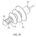
- FIG. 7Ashows an earplug 700 , according to one embodiment of the invention.
- Different regions of the ear anatomyhave different levels of electrical resistance. Electrical current flows preferentially through areas of lower resistance.
- the tympanic membranehas a lower resistance than areas of cartilage in the ear canal. It is desirable to prevent unwanted electrical contact to higher resistance areas, and also desirable to limit the amount of current delivered for patient comfort. Placing the electrode as close to the tympanic membrane as possible helps achieve a positive outcome because it helps reduce overall current delivery.
- the ear canalis known to be tortuous and thus placing an electrode near the tympanic membrane is difficult without contacting other areas of the ear. The earplug 700 solves these difficulties.
- the earplug 700includes a sealing body 702 for sealing the earplug 700 in an ear canal.
- the sealing body 702may include the construction of other similar earplugs disclosed herein.
- the sealing body 702may or may not include lumens and vents for filling the ear canal.
- the earplug 700includes an insulation body 704 which runs throughout the sealing body 702 .
- the extended portion 706 of the insulation body 704houses an electrode 708 .
- the extended portion 706is advantageous because it extends the electrode 708 well past the sealing body and closer in use to the tympanic membrane.
- the distal portion 706also may contact portions of the ear canal while still providing insulation for the electrode 708 .
- FIGS. 7B and 7Cshow perspective and cross-sectional views respectively, of an alternative extended portion 710 , which may be used with for example the earplug 700 shown in FIG. 7A .
- the extended portion 710features multiple slits 712 which provide fluid access to the inner electrode 714 .
- the extended portion 710may be formed from a hypotube which has been cut and coated with an external insulating barrier. The extended portion is advantageous because it reduces the amount of parts needed, and also lowers current density by using a relatively large surface area for the electrode 714 . Lower current density has been found to increase patient comfort.
- the domed portionmay be 710 may be removed and also more or less slits 712 than shown may be used.
- FIG. 7Dshows a perspective view, of an alternative extended portion 710 , which may be used with for example the earplug 700 shown in FIG. 7A .
- the extended portion 710includes insulating portions 716 a , 716 b , and electrode 718 .
- the electrode 718may be constructed from a super elastic alloy, such as nickel titanium. And thus when electrode 716 a comes into contact with portions of the ear canal, the electrode 718 will easily deflect as needed.
- the electrode 718may be longer than shown, and includes multiple insulating portions 716 b , to further extend the electrode 718 near the tympanic membrane.
- FIG. 7Eshows a perspective view, of an alternative extended portion 720 , which may be used with for example the earplug 700 shown in FIG. 7A .
- the extended portion 720is of a hypotube construction similar to what is shown in FIGS. 7B and 7C .
- the extended portion 720includes multiple drilled holes 722 which allow fluid communication with an inner electrode portion 724 , shown by the darker areas.
- the extended portion 720may be formed from a hypotube which has been cut and drilled, and coated with an external insulating barrier.
- FIG. 7Fshows a perspective view, of an alternative extended portion 726 , which may be used with for example the earplug 700 shown in FIG. 7A .
- Extended portion 726may be configured as an easily deformable but resilient basket. When the extended portion 726 comes into contact with portions of an ear canal, it will easily deflect.
- the extended portion 728is constructed from an outer insulating material 728 and an inner conducting portion 730 .
- the extended portion 726may be constructed from a super elastic material such as nickel titanium, and of thin proportions, for example less than 0.005 inches thick.
- FIG. 7Gshows a perspective view, of an alternative extended portion 732 , which may be used with for example the earplug 700 shown in FIG. 7A .
- the extended portion 732includes an outer insulating member 734 and a plurality of electrodes 736 .
- the plurality of electrodes 736are extended within the insulating member 734 .
- This configurationis advantageous because it greatly increases the conductive surface area and thus helps reduce current density. This configuration also directs current flow in a distal direction towards the tympanic membrane when in use.
- FIG. 7Hshows a perspective view, of an alternative extended portion 738 , which may be used with for example the earplug 700 shown in FIG. 7A .
- the extended portion 738is similar to the extended portion shown in FIG. 7F .
- the electrodes 742are insulated up until a distal most point as shown. This configuration also directs current flow in a distal direction towards the tympanic membrane when in use.
- FIGS. 7I and 7Jshow perspective and exploded views respectively, of an alternative extended portion 744 , which may be used with for example the earplug 700 shown in FIG. 7A .
- the extended portion 744includes a coiled configuration as shown, which further includes a laminated construction.
- the laminated constructionincludes an outer insulating member 746 , a conducting member 748 , and a inner insulating member 750 .
- the inner insulating member 750includes openings 752 which expose the conducting member 750 .
- the extended portion 744may be constructed from an initially coated flat wire, which is subsequently cut on one side to form openings 752 , and further coiled into shape.
- FIGS. 8A and 8Bshow side and operational views respectively, of an expandable earplug, according to one embodiment of the invention.
- Earplug 800includes an outer expandable portion 802 and an expander 804 .
- the outer expandable portion 802 and the expandermay be connected internally near the distal end of the earplug, as shown.
- the expander 804is slideable within the expandable portion, and may be withdrawn proximally to force the outer expandable portion to expand into a second configuration, as shown in FIG. 8B .
- the outer expandable portion 802may be constructed from a soft polymer, for example silicone. This configuration is advantageous because it allows for a precise fit within the anatomy of a specific ear, and also allows deeper positioning.
- FIG. 9Ashows a foam plug device 900 , according to one embodiment of the invention.
- the foam plug device 900includes an electrode 902 and a perforated tube 904 attached to the electrode 902 .
- a foam plug 906surrounds the electrode 902 .
- the foam plug 906can have a cylindrical or conical shape, and can be constructed from open celled foam.
- the electrode 902can be constructed from a malleable metal (e.g., silver) solid or stranded wire, or a solid or perforated tube, and include insulation 908 leading from the proximal end of the perforated tube 904 .
- An electrical connector(not shown) can connect to the proximal end of the electrode 902 .
- the perforated tube 904can be constructed from a flexible and insulative or conductive material, and generally includes perforations throughout.
- the foam plug device 900can also include additional sealing elements (not shown) and/or adhesives, as described herein.
- the foam plug 906can be compressed, inserted into an ear canal, and then allowed to expand to seal the ear canal.
- Drug solutioncan be introduced into the ear canal prior to insertion of the foam plug device 900 , or after due to the open cell nature of the foam plug 902 .
- the porosity of the foam plugcan allow drug solution contact throughout the length of the perforated tube 904 , thereby increasing electrode surface area via the perforations in the perforated tube 904 .
- the porosity of the foam plugcan also prevent pressure build-up during an iontophoresis procedure.
- FIG. 9Bshows a foam balloon device 910 , according to one embodiment of the invention.
- the foam balloon device 910includes an electrode 912 .
- the electrode 912can be constructed from a malleable metal (e.g., silver) solid or stranded wire, or solid or perforated tube.
- the electrode 912may include an outer lumen (not shown) which can be manufactured from a polyether block amide (e.g., Pebax® 55D) with an inner diameter of about 0.060′′ and an outer diameter of about 0.072′′.
- An electrical connector(not shown) can connect to the proximal end of the electrode.
- the electrode 912can also include a distal end with an expanded insulator surrounding a plurality of wire strands.
- a foam plug 914surrounds the electrode 912 .
- the foam plug 914may be constructed from open celled foam.
- a polyether foam (EC85HDE) with a density of 5 lb/ft 3 , and manufactured by Foamex Innovations, Inc.has been found to be suitable.
- the foam plugcan have a cylindrical shape with an outer diameter of 5-15 mm, and an inner diameter of 2.5 mm. Outer diameters of 8.3 mm and 11 mm have been used.
- the foam plugcan have other shapes, such as conical.
- the foam plugis encased by a double walled balloon 916 .
- the double walled balloon 916can be constructed from a compliant, semi-compliant, or non-compliant material.
- the double walled balloon 916can be formed by dip coating a shaped mandrel with a silicone, such as MED10-6400 manufactured by NuSil Technology LLC. The double walled balloon 916 can then be adhered to a portion of the electrode 912 and then partially inverted to create a double wall. The foam plug 914 can then be inserted into the space between the walls. The distal portion of the balloon 916 can be connected to a suction coupler 918 , such as T connector 88207 available from Qosina Corp.
- a suction coupler 918such as T connector 88207 available from Qosina Corp.
- a vacuumcan be applied to the suction coupler 918 , which causes the foam plug 914 to collapse.
- the foam balloon device 910can then be inserted into an ear canal. Once in place, the vacuum can be discontinued which causes the foam 914 to expand.
- the foam 914 expansionpresses the double walled balloon 916 in contact with the ear canal walls to fluidly seal drug solution within the ear canal. As positive air pressure is not used to inflate the double walled balloon, the danger of balloon rupture is negated. Vacuum may be reapplied to re-collapse the foam 914 in order to aid in removal.
- FIG. 10Ashows a speculum port 1000 , according to an embodiment of the invention.
- the speculum port 1000can have a generally conical shape.
- the speculum port 1000can be constructed from a polymer or metal alloy.
- the speculum port 1000may be relatively flexible or stiff.
- the speculum port 1000can include a proximal port 1002 which is removably coupled to a distal port 1004 .
- the proximal port 1002can be coupled to the distal port 1004 by a slight interference fit or by a threaded connection.
- An inner plug 1006can be removably and sealably coupled to the distal port 1004 .
- the inner plug 1006includes an electrode 1008 , which is configured as a looped electrode as shown in FIG.
- the electrode 1008can generally take the form of any of the electrodes disclosed herein.
- the inner plug 1006can include sealing members (not shown) configured similarly to other sealing members disclosed herein.
- the distal port 1004can include an adhesive layer 1010 which may take the form of any of the adhesives disclosed herein.
- the adhesive layer 1010may also be a layer of pliable silicone putty, ostomy bag adhesive gasket material, expanding foam, impression material, gel, bone wax, balloon cement, or a silicone gasket.
- FIG. 10Bshows an alternative distal port 1012 , according to one embodiment of the invention.
- the distal port 1012is configured similarly to distal port 1004 , however, distal port 1012 includes an electrode surface 1014 .
- the electrode surface 1014can be a layer of metal, such as silver, coupled to the interior surface of the distal port 1004 .
- An inner plug 1016can removably and sealably couple to the distal port 1012 .
- the inner plug 1016can include contact surface 1018 which can make electrical contact with the electrode surface when the inner plug 1016 couples to the distal port 1004 .
- FIG. 10Cshows an alternative distal port 1020 , according to one embodiment of the invention.
- the distal port 1012is configured similarly to distal port 1004 , however, distal port 1012 couples to a plug with a plurality of tentacle electrodes 1022 .
- the tentacle electrodes 1022are highly flexible and provide increased surface area.
- the tentacle electrodes 1022can include insulative and conductive areas of exposed metal.
- FIGS. 10D and 10Eshow the speculum port 1000 in use, according to one embodiment of the invention.
- the speculum port 1000can be handled by the proximal port 1002 .
- the increased diameter of the proximal port 1002allows for finger manipulation and insertion of the speculum port 1000 .
- the speculum portcan be adjusted to provide visualization of the tympanic membrane.
- the adhesive layer 1010 on the distal port 1004provides a fluid tight seal and fixation between the distal port 1004 and the ear canal.
- the proximal port 1002can be decoupled from the distal port 1004 .
- the distal port 1004can then be filled with a drug solution and the inner plug 1006 can be inserted into the distal port 1004 .
- the inner plug 1006can then be supplied with electrical current to complete the iontophoresis procedure.
- FIGS. 10F through 10Hshow the speculum port 1000 in use, according to one embodiment of the invention.
- the speculum port 1000includes alternative distal port 1012 with electrode surface 1014 .
- the distal port 1012has already been placed in the ear canal and the proximal port 1002 has been removed, in accordance with FIGS. 10D and 10E .
- the distal port 1012can be filled with a drug solution, and the inner plug 1016 can be inserted into the distal port 1012 .
- the inner plug 1016can then be supplied with electrical current to complete the iontophoresis procedure.
- FIG. 11shows a simplified support structure 1100 that is worn on the patient's head, according to one embodiment of the invention.
- the simplified support structure 1100is worn on the patient's head while the patient is awake and upright.
- the support structure 1100is configured to hold the one or more systems described herein in alignment with the patient's ears E.
- the support structure 1100can have an alignment structure with a first body 1110 engaging the first ear, a second body 1110 engaging the second ear, and a member extending around the head of the patient between the first and second body. Any of the earplugs of the present invention may be coupled to the head via a headset as in FIG. 11 .
- FIG. 12shows a simplified support structure 1200 that is worn on the patient's head, according to one embodiment of the invention.
- the support structure 1200is configured similarly to eyeglasses and can be worn in a similar fashion.
- Earplugs 1210are hingably connected to the support structure 1200 and can be leveraged into ear canals by the support structure 1200 .
- the earplugs 1210can be configured similarly to any of the earplugs disclosed herein.
- the support structure 1200can prevent unwanted movement and provide sealing force against the earplugs 1210 .
- the support structure 1200can include adjustable elements to adjust width and length for various sized patients.
- the support structure 1200can include visual panels, such as LCD panels which can provide video viewing for the patient.
- the earplugs 1210can also include speakers to supply audio to the patient.
Landscapes
- Health & Medical Sciences (AREA)
- Life Sciences & Earth Sciences (AREA)
- Public Health (AREA)
- Engineering & Computer Science (AREA)
- Biomedical Technology (AREA)
- Veterinary Medicine (AREA)
- Animal Behavior & Ethology (AREA)
- General Health & Medical Sciences (AREA)
- Heart & Thoracic Surgery (AREA)
- Vascular Medicine (AREA)
- Radiology & Medical Imaging (AREA)
- Nuclear Medicine, Radiotherapy & Molecular Imaging (AREA)
- Physics & Mathematics (AREA)
- Acoustics & Sound (AREA)
- Biophysics (AREA)
- Otolaryngology (AREA)
- Psychology (AREA)
- Anesthesiology (AREA)
- Hematology (AREA)
- Electrotherapy Devices (AREA)
Abstract
Description
Claims (20)
Priority Applications (1)
| Application Number | Priority Date | Filing Date | Title |
|---|---|---|---|
| US13/798,635US9713710B2 (en) | 2008-07-31 | 2013-03-13 | Systems and methods for anesthetizing ear tissue |
Applications Claiming Priority (3)
| Application Number | Priority Date | Filing Date | Title |
|---|---|---|---|
| US8536008P | 2008-07-31 | 2008-07-31 | |
| US12/510,217US8452392B2 (en) | 2008-07-31 | 2009-07-27 | Systems and methods for anesthetizing ear tissue |
| US13/798,635US9713710B2 (en) | 2008-07-31 | 2013-03-13 | Systems and methods for anesthetizing ear tissue |
Related Parent Applications (1)
| Application Number | Title | Priority Date | Filing Date |
|---|---|---|---|
| US12/510,217ContinuationUS8452392B2 (en) | 2008-07-31 | 2009-07-27 | Systems and methods for anesthetizing ear tissue |
Publications (2)
| Publication Number | Publication Date |
|---|---|
| US20130197426A1 US20130197426A1 (en) | 2013-08-01 |
| US9713710B2true US9713710B2 (en) | 2017-07-25 |
Family
ID=41609087
Family Applications (2)
| Application Number | Title | Priority Date | Filing Date |
|---|---|---|---|
| US12/510,217Expired - Fee RelatedUS8452392B2 (en) | 2008-07-31 | 2009-07-27 | Systems and methods for anesthetizing ear tissue |
| US13/798,635Expired - Fee RelatedUS9713710B2 (en) | 2008-07-31 | 2013-03-13 | Systems and methods for anesthetizing ear tissue |
Family Applications Before (1)
| Application Number | Title | Priority Date | Filing Date |
|---|---|---|---|
| US12/510,217Expired - Fee RelatedUS8452392B2 (en) | 2008-07-31 | 2009-07-27 | Systems and methods for anesthetizing ear tissue |
Country Status (11)
| Country | Link |
|---|---|
| US (2) | US8452392B2 (en) |
| EP (1) | EP2328653B1 (en) |
| JP (1) | JP5323935B2 (en) |
| KR (1) | KR101610139B1 (en) |
| CN (1) | CN102119041B (en) |
| AU (1) | AU2009276384B2 (en) |
| BR (1) | BRPI0916756A2 (en) |
| CA (1) | CA2732595C (en) |
| ES (1) | ES2393697T3 (en) |
| MX (1) | MX2011001100A (en) |
| WO (1) | WO2010014894A1 (en) |
Cited By (11)
| Publication number | Priority date | Publication date | Assignee | Title |
|---|---|---|---|---|
| US10016304B2 (en) | 2015-07-16 | 2018-07-10 | Tusker Medical, Inc. | Earplug assembly for iontophoresis system |
| US10130808B2 (en) | 2013-03-14 | 2018-11-20 | Tusker Medical, Inc. | System and method for providing iontophoresis at tympanic membrane |
| US10258776B2 (en) | 2007-04-19 | 2019-04-16 | Tusker Medical, Inc. | System and method for treatment of target tissues within the ears |
| US10478344B2 (en) | 2012-05-30 | 2019-11-19 | Tusker Medical, Inc. | Adhesive earplugs useful for sealing the ear canal |
| US10576277B2 (en) | 2007-12-20 | 2020-03-03 | Tusker Medical, Inc. | Iontophoresis methods |
| US10751531B2 (en) | 2008-07-31 | 2020-08-25 | Tusker Medical, Inc. | Systems and methods for anesthetizing ear tissue |
| US11045614B2 (en) | 2011-07-25 | 2021-06-29 | Tusker Medical, Inc. | Personalizable system and method for anesthetizing the tympanic membrane |
| US12128200B2 (en) | 2016-06-30 | 2024-10-29 | Safkan, Inc. | Ear cleaning devices and methods |
| USD1057151S1 (en) | 2019-11-22 | 2025-01-07 | Safkan, Inc. | Reservoir for ear cleaning device |
| USD1091805S1 (en) | 2019-11-22 | 2025-09-02 | Safkan, Inc. | Nozzle for ear cleaning device |
| USD1091806S1 (en) | 2019-11-22 | 2025-09-02 | Safkan, Inc. | Ear cleaning device |
Families Citing this family (41)
| Publication number | Priority date | Publication date | Assignee | Title |
|---|---|---|---|---|
| US7351246B2 (en)* | 2004-01-20 | 2008-04-01 | Epley John M | Minimally invasive, sustained, intra-tympanic drug delivery system |
| US8340310B2 (en)* | 2007-07-23 | 2012-12-25 | Asius Technologies, Llc | Diaphonic acoustic transduction coupler and ear bud |
| US8391534B2 (en) | 2008-07-23 | 2013-03-05 | Asius Technologies, Llc | Inflatable ear device |
| US20110228964A1 (en)* | 2008-07-23 | 2011-09-22 | Asius Technologies, Llc | Inflatable Bubble |
| US8774435B2 (en) | 2008-07-23 | 2014-07-08 | Asius Technologies, Llc | Audio device, system and method |
| US8452392B2 (en) | 2008-07-31 | 2013-05-28 | Acclarent, Inc. | Systems and methods for anesthetizing ear tissue |
| US20100312338A1 (en)* | 2009-06-05 | 2010-12-09 | Entrigue Surgical, Inc. | Systems, devices and methods for providing therapy to an anatomical structure |
| BR112012028015A2 (en) | 2010-05-02 | 2017-03-28 | Lake Biosciences Llc | apparatus and method |
| US9272157B2 (en) | 2010-05-02 | 2016-03-01 | Nervive, Inc. | Modulating function of neural structures near the ear |
| EP2636225A2 (en)* | 2010-11-03 | 2013-09-11 | Asius Technologies, Llc | Audio device, system and method |
| JP6580298B2 (en)* | 2010-12-16 | 2019-09-25 | サイオン・ニューロスティム,リミテッド・ライアビリティ・カンパニー | Vestibular stimulation device and vestibular stimulation system |
| US9011363B2 (en)* | 2012-04-10 | 2015-04-21 | Acclarent, Inc. | Tympanic membrane pressure equalization tube |
| US20140119586A1 (en)* | 2012-10-25 | 2014-05-01 | Sonion A/S | Hearing aid assembly |
| US10065047B2 (en) | 2013-05-20 | 2018-09-04 | Nervive, Inc. | Coordinating emergency treatment of cardiac dysfunction and non-cardiac neural dysfunction |
| US12396892B2 (en) | 2013-06-28 | 2025-08-26 | Nocira, Llc | External ear canal pressure regulation device |
| US10251790B2 (en) | 2013-06-28 | 2019-04-09 | Nocira, Llc | Method for external ear canal pressure regulation to alleviate disorder symptoms |
| US9039639B2 (en) | 2013-06-28 | 2015-05-26 | Gbs Ventures Llc | External ear canal pressure regulation system |
| US9510743B2 (en) | 2013-12-17 | 2016-12-06 | Biovision Technologies, Llc | Stabilized surgical device for performing a sphenopalatine ganglion block procedure |
| US10016580B2 (en) | 2013-12-17 | 2018-07-10 | Biovision Technologies, Llc | Methods for treating sinus diseases |
| US9516995B2 (en) | 2013-12-17 | 2016-12-13 | Biovision Technologies, Llc | Surgical device for performing a sphenopalatine ganglion block procedure |
| US9694163B2 (en) | 2013-12-17 | 2017-07-04 | Biovision Technologies, Llc | Surgical device for performing a sphenopalatine ganglion block procedure |
| WO2015179207A1 (en)* | 2014-05-19 | 2015-11-26 | Cain Frank J | Biomedical aural delivery systems and methods |
| CN104218165A (en)* | 2014-08-20 | 2014-12-17 | 京东方科技集团股份有限公司 | Organic light-emitting diode device and display device |
| USD772406S1 (en) | 2014-12-16 | 2016-11-22 | Biovision Technologies, Llc | Surgical device |
| WO2017004268A1 (en) | 2015-06-29 | 2017-01-05 | 480 Biomedical, Inc. | Implantable scaffolds for treatment of sinusitis |
| EP3313330A4 (en) | 2015-06-29 | 2019-03-20 | 480 Biomedical, Inc. | SUPPORT LOADING AND DISTRIBUTION SYSTEMS |
| US10232082B2 (en) | 2015-06-29 | 2019-03-19 | 480 Biomedical, Inc. | Implantable scaffolds for treatment of sinusitis |
| US10973664B2 (en) | 2015-12-30 | 2021-04-13 | Lyra Therapeutics, Inc. | Scaffold loading and delivery systems |
| US10760566B2 (en) | 2016-07-22 | 2020-09-01 | Nocira, Llc | Magnetically driven pressure generator |
| KR200483115Y1 (en)* | 2016-12-05 | 2017-04-05 | 오호준 | Eearplug |
| EP4424293A3 (en) | 2017-02-27 | 2024-11-27 | Nocira, LLC | Ear pumps |
| US10201639B2 (en) | 2017-05-01 | 2019-02-12 | 480 Biomedical, Inc. | Drug-eluting medical implants |
| CN111511265A (en) | 2018-01-16 | 2020-08-07 | 塔斯克医药股份有限公司 | Visualization device and method for otology procedure |
| JP7471223B2 (en) | 2018-01-16 | 2024-04-19 | タスカー メディカル,インコーポレイテッド | EARSET ASSEMBLY FOR PROVIDING IONTOPHORESIS INCLUDES VALVE - Patent application |
| KR102121497B1 (en)* | 2018-03-16 | 2020-06-10 | 의료법인 성광의료재단 | Intratympanic current supply device and intratympanic current supply method using the same |
| EP3810049A4 (en) | 2018-06-22 | 2022-03-23 | Nocira, LLC | Systems and methods for treating neurological disorders |
| WO2020005910A1 (en) | 2018-06-28 | 2020-01-02 | Sandler Scientific, Llc | Sino-nasal rinse delivery device with agitation, flow-control and integrated medication management system |
| CN110575157A (en)* | 2019-09-16 | 2019-12-17 | 张仕林 | A disposable tympanic membrane electrode for electrocochlear examination |
| CN111513923B (en)* | 2020-05-18 | 2022-08-12 | 黄津博 | Ear-blocking type hearing protection device |
| US20240245602A1 (en)* | 2020-08-28 | 2024-07-25 | President And Fellows Of Harvard College | Drug combination kits and methods of drug delivery |
| WO2022072114A1 (en)* | 2020-09-29 | 2022-04-07 | Smith & Nephew, Inc. | Systems and methods for delivering an anesthetizing solution into the ear canal |
Citations (133)
| Publication number | Priority date | Publication date | Assignee | Title |
|---|---|---|---|---|
| US858673A (en) | 1906-08-30 | 1907-07-02 | Charles R Roswell | Device adapted for curing deafness. |
| US1920006A (en) | 1932-07-26 | 1933-07-25 | Edward A Arnim Jr | Prostatic catheter |
| US2458884A (en) | 1946-01-03 | 1949-01-11 | Volkmann John | Ear protector valve |
| US3741197A (en) | 1970-09-04 | 1973-06-26 | Micromedia Syst Inc | Percussion apparatus for blood sampling |
| US3888258A (en) | 1972-11-07 | 1975-06-10 | Taichiro Akiyama | Drain for the eardrum and apparatus for introducing the same |
| US3897786A (en) | 1971-02-05 | 1975-08-05 | Richards Mfg Co | Disposable myringotomy apparatus |
| US3913584A (en) | 1974-06-28 | 1975-10-21 | Xomox Corp | Combination myringotomy scalpel, aspirator and otological vent tube inserter |
| US3948271A (en) | 1972-11-07 | 1976-04-06 | Taichiro Akiyama | Drain for the eardrum and apparatus for introducing the same |
| US3991755A (en) | 1973-07-27 | 1976-11-16 | Medicon, Inc. | Iontophoresis apparatus for applying local anesthetics |
| US4149533A (en) | 1976-10-13 | 1979-04-17 | Matsushita Electric Industrial Co., Ltd. | Device for iontophoretic application of fluoride on tooth |
| JPS5821431A (en) | 1981-07-29 | 1983-02-08 | Hitachi Cable Ltd | Foamed material composition prepared with fluorine- containing copolymer |
| US4406282A (en) | 1981-02-20 | 1983-09-27 | Parker Bruce W | Earplug for an underwater diver |
| FR2526656A1 (en) | 1982-05-12 | 1983-11-18 | Dumas Yves | Ear syringe using recycled water - has flexible vessel collecting water from bowl shaped to fit patient's ear |
| JPS59129815A (en) | 1983-01-18 | 1984-07-26 | Sumitomo Electric Ind Ltd | Method and device for assembling sleeve inside of photoelectric element |
| US4468218A (en) | 1982-09-24 | 1984-08-28 | Armstrong Beverly W | Ventilation tube for the middle ear and method of implanting same |
| US4473073A (en) | 1982-01-20 | 1984-09-25 | Microtek Medical Incorporated | Myringotomy tube inserter and method for inserting myringotomy tubes |
| US4552137A (en) | 1983-08-16 | 1985-11-12 | Strauss Richard H | Earplugs |
| US4564009A (en) | 1983-08-24 | 1986-01-14 | Mine Safety Appliances Company | Universal ear plug |
| US4601294A (en)* | 1982-01-25 | 1986-07-22 | Minnesota Mining And Manufacturing Company | Ear canal electrode |
| CN86105171A (en) | 1985-08-21 | 1987-03-04 | 明尼苏达州采矿制造公司 | Electrode close to tympanic membrane and method for stimulating and recording signals |
| US4712537A (en) | 1986-08-13 | 1987-12-15 | Pender Daniel J | Apparatus for treating recurrent ear infections |
| US4968296A (en) | 1989-12-20 | 1990-11-06 | Robert Ritch | Transscleral drainage implant device for the treatment of glaucoma |
| US4971076A (en) | 1987-09-25 | 1990-11-20 | Barbara Densert | Method of ventilating the middle ear by means of a ventilation tube which can be applied in the tympanic membrane |
| US5026378A (en) | 1989-11-09 | 1991-06-25 | Goldsmith Iii Manning M | Punch myringotomy system and method |
| US5044373A (en) | 1989-02-01 | 1991-09-03 | Gn Danavox A/S | Method and apparatus for fitting of a hearing aid and associated probe with distance measuring means |
| US5047007A (en) | 1989-12-22 | 1991-09-10 | Medtronic, Inc. | Method and apparatus for pulsed iontophoretic drug delivery |
| US5053040A (en) | 1989-11-09 | 1991-10-01 | Goldsmith Iii Manning M | Method of performing a myringotomy |
| CN2087067U (en) | 1991-04-03 | 1991-10-23 | 胡广艾 | Therapeutic apparatus for otitis media |
| US5107861A (en) | 1990-12-10 | 1992-04-28 | Lillian Narboni | Safe ear clean button and protection with attachment device |
| WO1992010223A1 (en) | 1990-12-07 | 1992-06-25 | Simeon B Schreiber | Method and apparatus for administering otologic medicament |
| US5135478A (en) | 1989-05-10 | 1992-08-04 | Drug Delivery Systems Inc. | Multi-signal electrical transdermal drug applicator |
| US5160316A (en) | 1990-09-10 | 1992-11-03 | Henley Julian L | Iontophoretic drug delivery apparatus |
| US5254081A (en) | 1991-02-01 | 1993-10-19 | Empi, Inc. | Multiple site drug iontophoresis electronic device and method |
| US5254120A (en) | 1992-02-11 | 1993-10-19 | Cinberg James Z | Myringotomy ventilliation tube, method, applicator and kit |
| US5261903A (en) | 1988-04-11 | 1993-11-16 | M.D. Inc. | Composite anesthetic article and method of use |
| USD352780S (en) | 1993-04-19 | 1994-11-22 | Valleylab Inc. | Combined suction, irrigation and electrosurgical handle |
| JPH07116190A (en) | 1993-10-21 | 1995-05-09 | Nagashima Ika Kikai Kk | Eardrum anesthesia machine and treatment machine |
| US5421818A (en) | 1993-10-18 | 1995-06-06 | Inner Ear Medical Delivery Systems, Inc. | Multi-functional inner ear treatment and diagnostic system |
| US5466239A (en) | 1992-07-28 | 1995-11-14 | Cinberg; James Z. | Myringotomy ventilation tube and associated method |
| US5496329A (en) | 1993-09-08 | 1996-03-05 | Alpha Surgical, Inc. | Method and apparatus for implanting a medical ventilation tube |
| US5610988A (en) | 1993-09-08 | 1997-03-11 | Sony Corporation | Hearing aid set |
| USD378611S (en) | 1995-10-19 | 1997-03-25 | Ethicon Endo-Surgery, Inc. | Electrosurgical instrument |
| US5643280A (en) | 1995-12-07 | 1997-07-01 | The Anspach Effort, Inc. | Integral myringotomy tube and inserter |
| US5674196A (en)* | 1996-01-05 | 1997-10-07 | Donaldson; John | Device for introducing medical fluid into the human ear |
| DE19618585A1 (en) | 1996-05-09 | 1997-11-13 | Michael Glimmann | Ear plug for tinnitus treatment |
| USD387863S (en) | 1996-07-22 | 1997-12-16 | Microvena Corporation | Medical device delivery handle |
| US5707383A (en) | 1995-10-05 | 1998-01-13 | Xomed Surgical Products, Inc. | Method of removing soft tissue in the middle ear |
| US5792100A (en) | 1995-05-19 | 1998-08-11 | Shantha; T. R. | Treatment method for transsphenoidal stimulation of the pituitary gland and of nerve structures |
| US5893828A (en) | 1996-05-02 | 1999-04-13 | Uram; Martin | Contact laser surgical endoscope and associated myringotomy procedure |
| USD418223S (en) | 1998-06-05 | 1999-12-28 | Eclipse Surgical Technologies, Inc. | Hand piece for surgical and biopsy procedures |
| USD420741S (en) | 1996-08-20 | 2000-02-15 | Ethicon Endo-Surgery, Inc. | Handle for an electrosurgical instrument |
| US6045528A (en) | 1997-06-13 | 2000-04-04 | Intraear, Inc. | Inner ear fluid transfer and diagnostic system |
| USD424197S (en) | 1999-02-12 | 2000-05-02 | Thermolase Corporation | Laser handpiece housing |
| US6059803A (en) | 1999-06-01 | 2000-05-09 | Spilman; Daniel A. | Ear vacuum |
| USD426135S (en) | 1999-09-02 | 2000-06-06 | Shu-Chen Lee | Tool handle |
| US6137889A (en) | 1998-05-27 | 2000-10-24 | Insonus Medical, Inc. | Direct tympanic membrane excitation via vibrationally conductive assembly |
| US6148821A (en)* | 1998-04-29 | 2000-11-21 | Cabot Safety Intermediate Corporation | Selective nonlinear attenuating earplug |
| CN2409940Y (en) | 2000-02-25 | 2000-12-13 | 陈向东 | Earplug type laser fibre-optical fixed support |
| US6183469B1 (en) | 1997-08-27 | 2001-02-06 | Arthrocare Corporation | Electrosurgical systems and methods for the removal of pacemaker leads |
| US6200280B1 (en) | 1998-05-29 | 2001-03-13 | Theracardia, Inc. | Cardiac massage apparatus and method |
| US6206888B1 (en) | 1997-10-01 | 2001-03-27 | Scimed Life Systems, Inc. | Stent delivery system using shape memory retraction |
| US6245077B1 (en) | 2000-01-21 | 2001-06-12 | Exmoor Plastics Ltd. | Universal myringotomy tube/aural grommet inserter and methods |
| US6251121B1 (en) | 1996-12-02 | 2001-06-26 | Angiotrax, Inc. | Apparatus and methods for intraoperatively performing surgery |
| US6295469B1 (en) | 1997-11-14 | 2001-09-25 | Alza Corporation | Formulation for electrically assisted delivery of lidocaine and epinephrine |
| USD450843S1 (en) | 2000-05-30 | 2001-11-20 | Boston Scientific Corporation | Thrombectomy handpiece |
| US6347246B1 (en) | 2000-02-03 | 2002-02-12 | Axelgaard Manufacturing Company, Ltd. | Electrotransport adhesive for iontophoresis device |
| US20020026125A1 (en) | 2000-08-25 | 2002-02-28 | Hans Leysieffer | Device for electromechanical stimulation and testing of hearing |
| US6358231B1 (en) | 1998-08-24 | 2002-03-19 | Biopolymer, Inc. | Transdermal anesthetizing solution and method and apparatus for anesthetizing the ear canal and tympanic membrane |
| US20020069883A1 (en) | 2000-12-08 | 2002-06-13 | Aviv Hirchenbain | Device for active regulation of pressure on outer ear |
| US20020111585A1 (en) | 2001-02-13 | 2002-08-15 | Scimed Life Systems, Inc. | Hemostasis valve |
| US6440102B1 (en)* | 1998-07-23 | 2002-08-27 | Durect Corporation | Fluid transfer and diagnostic system for treating the inner ear |
| US20020138091A1 (en) | 2001-03-23 | 2002-09-26 | Devonrex, Inc. | Micro-invasive nucleotomy device and method |
| US20020161379A1 (en) | 2001-04-26 | 2002-10-31 | Kaplan Aaron V. | Mechanically registered videoscopic myringotomy/tympanostomy tube placement system |
| US6475138B1 (en) | 1995-07-12 | 2002-11-05 | Laser Industries Ltd. | Apparatus and method as preparation for performing a myringotomy in a child's ear without the need for anaesthesia |
| US20020169456A1 (en) | 2001-05-10 | 2002-11-14 | Hosheng Tu | Delivery system for a stentless valve bioprosthesis |
| US6512950B2 (en) | 2000-02-18 | 2003-01-28 | University Of Utah Research Foundation | Methods for delivering agents using alternating current |
| US6514261B1 (en) | 1998-09-30 | 2003-02-04 | Impra, Inc. | Delivery mechanism for implantable stent |
| US6522827B1 (en) | 2000-10-11 | 2003-02-18 | Trimedyne, Inc. | Laser devices for performing a myringotomy |
| US20030060799A1 (en) | 2001-09-21 | 2003-03-27 | Arenberg Michael H. | Aural catheter system including anchor balloon and balloon inflation device |
| US6553253B1 (en) | 1999-03-12 | 2003-04-22 | Biophoretic Therapeutic Systems, Llc | Method and system for electrokinetic delivery of a substance |
| US20030093057A1 (en) | 2001-07-31 | 2003-05-15 | Jie Zhang | Methods and formulations for photodynamic therapy |
| US20030199791A1 (en) | 2002-04-19 | 2003-10-23 | Pelikan Technologies, Inc. | Method and apparatus for penetrating tissue |
| US6640121B1 (en) | 1999-08-10 | 2003-10-28 | The University Of Miami | Otic microprobe for neuro-cochlear monitoring |
| US6645173B1 (en) | 2002-03-29 | 2003-11-11 | Barbara Liebowitz | Dripless eardrop applicator |
| US20040054339A1 (en) | 2001-01-26 | 2004-03-18 | Danuta Ciok | Cleansing appliance |
| US20050094835A1 (en)* | 2003-11-03 | 2005-05-05 | Marc Doty | Low sound attenuating hearing protection device |
| US6916159B2 (en) | 2002-10-09 | 2005-07-12 | Therasense, Inc. | Device and method employing shape memory alloy |
| US20050182385A1 (en) | 2004-01-20 | 2005-08-18 | Epley John M. | Minimally invasive, sustained, intra-tympanic drug delivery system |
| US20050240147A1 (en) | 2004-04-21 | 2005-10-27 | Exploramed Ii, Inc. | Devices, systems and methods for diagnosing and treating sinusitus and other disorders of the ears, nose and/or throat |
| US20050235422A1 (en) | 2004-04-09 | 2005-10-27 | Arthur Wallace | Audiovisual distraction in patients undergoing surgery with regional anesthesia |
| US20060142700A1 (en) | 2003-06-20 | 2006-06-29 | Sobelman Owen S | Two-way slit valve |
| US20060177080A1 (en)* | 2005-01-25 | 2006-08-10 | Smith Richard C | Earpiece with flanged extension |
| US7123957B2 (en) | 1998-11-09 | 2006-10-17 | Transpharma Medical Ltd. | Transdermal drug delivery and analyte extraction |
| US7127285B2 (en) | 1999-03-12 | 2006-10-24 | Transport Pharmaceuticals Inc. | Systems and methods for electrokinetic delivery of a substance |
| WO2006119512A2 (en) | 2005-05-05 | 2006-11-09 | University Of Virginia Patent Foundation | Surgical tool and insertion device for tube placement |
| US7137975B2 (en) | 2001-02-13 | 2006-11-21 | Aciont, Inc. | Method for increasing the battery life of an alternating current iontophoresis device using a barrier-modifying agent |
| USD535027S1 (en) | 2004-10-06 | 2007-01-09 | Sherwood Services Ag | Low profile vessel sealing and cutting mechanism |
| US20070078372A1 (en) | 2005-09-30 | 2007-04-05 | Vyteris, Inc. | Iontophoresis Drug Delivery Formulation Providing Acceptable Sensation and Dermal Anesthesia |
| US20070183613A1 (en)* | 2004-05-28 | 2007-08-09 | Juneau Roger P | Self forming in-the-ear hearing aid with conical stent |
| US20070233222A1 (en) | 2006-02-21 | 2007-10-04 | Med Institute, Inc. | Split sheath deployment system |
| US20080011308A1 (en) | 2006-07-12 | 2008-01-17 | Thomas Walter Fleming | Reverse fitting earplug |
| US20080051804A1 (en) | 2005-05-05 | 2008-02-28 | Cottler Shayn P | Tube, stent and collar insertion device |
| US20080058756A1 (en) | 2006-09-05 | 2008-03-06 | Transcu Ltd. | Non-destructive systems, devices, and methods for evaluating iontophoresis drug delivery devices |
| WO2008030485A2 (en) | 2006-09-07 | 2008-03-13 | Neurosystec Corporation | Catheter for localized drug delivery and/or electrical stimulation |
| US7344507B2 (en) | 2002-04-19 | 2008-03-18 | Pelikan Technologies, Inc. | Method and apparatus for lancet actuation |
| US20080107287A1 (en) | 2006-11-06 | 2008-05-08 | Terry Beard | Personal hearing control system and method |
| US7381210B2 (en) | 2003-03-14 | 2008-06-03 | Edwards Lifesciences Corporation | Mitral valve repair system and method for use |
| US20080212416A1 (en) | 2006-12-20 | 2008-09-04 | Roland Polonio | Notification device and method for programming a notification device |
| US20080262468A1 (en) | 2007-04-19 | 2008-10-23 | Acclarent, Inc. | System and Method for the Simultaneous Bilateral Treatment of Target Tissues Within the Ears Using a Guide Block Structure |
| WO2009010788A1 (en) | 2007-07-13 | 2009-01-22 | Braun Air Ears Limited | Aural device |
| US20090163848A1 (en) | 2007-12-20 | 2009-06-25 | Acclarent, Inc. | Iontophoresis Methods |
| USD595410S1 (en) | 2007-05-07 | 2009-06-30 | Derma Dream Ltd. | Demabrasion applicator |
| USD598543S1 (en) | 2006-06-13 | 2009-08-18 | Angiomed Gmbh & Co. Medizintechnik Kg | Handle for a medical delivery device |
| US20090209972A1 (en) | 2008-02-20 | 2009-08-20 | Loushin Michael K H | Ventilation Device and Insertion System Therefor |
| US20090262510A1 (en) | 2003-12-10 | 2009-10-22 | Nokia Corporation | Apparatus and arrangement for shielding a light emitting diode against electrostatic discharge |
| US20090270807A1 (en)* | 2008-04-23 | 2009-10-29 | Medtronic Vascular, Inc. | Aspiration Catheter Having An Internal Vacuum Accumulator |
| US20090299344A1 (en) | 2005-07-20 | 2009-12-03 | Woojin Lee | Surgical instrument guide device |
| WO2010014894A1 (en) | 2008-07-31 | 2010-02-04 | Acclarent, Inc. | Systems and methods for anesthetizing ear tissue |
| US20100041447A1 (en) | 2008-08-13 | 2010-02-18 | Will Wang Graylin | Wearable headset with self-contained vocal feedback and vocal command |
| US20100061581A1 (en) | 2008-09-09 | 2010-03-11 | Creative Technology Ltd | Sound producing device |
| US20100198135A1 (en) | 2008-07-31 | 2010-08-05 | Acclarent, Inc. | Systems and methods for anesthetizing ear tissue |
| USD622842S1 (en) | 2009-08-06 | 2010-08-31 | Given Imaging Ltd. | Implantable monitor delivery device handle |
| US20100300460A1 (en) | 2009-05-27 | 2010-12-02 | 3M Innovative Properties Company | Earplug |
| US20110001564A1 (en) | 2008-03-04 | 2011-01-06 | Shinichi Hori | Variable gain amplifier |
| US20110015645A1 (en) | 2009-07-15 | 2011-01-20 | Greg Liu | Tympanic membrane pressure equalization tube delivery system |
| US20110048414A1 (en) | 2008-02-07 | 2011-03-03 | University Of Washington | Circumferential aerosol device |
| US20110268303A1 (en) | 2010-04-29 | 2011-11-03 | Cochlear Limited | Bone conduction device having limited range of travel |
| WO2013016098A2 (en) | 2011-07-25 | 2013-01-31 | Acclarent, Inc. | Personalizable system and method for anesthetizing the tympanic membrane |
| US20130223702A1 (en) | 2012-02-22 | 2013-08-29 | Veran Medical Technologies, Inc. | Systems, methods and devices for forming respiratory-gated point cloud for four dimensional soft tissue navigation |
| WO2013181009A1 (en) | 2012-05-30 | 2013-12-05 | Acclarent, Inc. | Adhesive earplugs useful for sealing the ear canal |
| US20140276352A1 (en) | 2013-03-14 | 2014-09-18 | Acclarent, Inc. | System and method for providing iontophoresis at tympanic membrane |
| US20140276906A1 (en) | 2013-03-14 | 2014-09-18 | Acclarent, Inc. | Features to improve and sense tympanic membrane apposition by tympanostomy tube delivery instrument |
| US9011363B2 (en) | 2012-04-10 | 2015-04-21 | Acclarent, Inc. | Tympanic membrane pressure equalization tube |
Family Cites Families (1)
| Publication number | Priority date | Publication date | Assignee | Title |
|---|---|---|---|---|
| US7024010B2 (en)* | 2003-05-19 | 2006-04-04 | Adaptive Technologies, Inc. | Electronic earplug for monitoring and reducing wideband noise at the tympanic membrane |
- 2009
- 2009-07-27USUS12/510,217patent/US8452392B2/ennot_activeExpired - Fee Related
- 2009-07-31AUAU2009276384Apatent/AU2009276384B2/ennot_activeCeased
- 2009-07-31CNCN200980130731.5Apatent/CN102119041B/ennot_activeExpired - Fee Related
- 2009-07-31KRKR1020117004163Apatent/KR101610139B1/ennot_activeExpired - Fee Related
- 2009-07-31WOPCT/US2009/052395patent/WO2010014894A1/enactiveApplication Filing
- 2009-07-31EPEP09791044Apatent/EP2328653B1/ennot_activeNot-in-force
- 2009-07-31BRBRPI0916756Apatent/BRPI0916756A2/ennot_activeIP Right Cessation
- 2009-07-31JPJP2011521352Apatent/JP5323935B2/ennot_activeExpired - Fee Related
- 2009-07-31CACA2732595Apatent/CA2732595C/ennot_activeExpired - Fee Related
- 2009-07-31ESES09791044Tpatent/ES2393697T3/enactiveActive
- 2009-07-31MXMX2011001100Apatent/MX2011001100A/enactiveIP Right Grant
- 2013
- 2013-03-13USUS13/798,635patent/US9713710B2/ennot_activeExpired - Fee Related
Patent Citations (179)
| Publication number | Priority date | Publication date | Assignee | Title |
|---|---|---|---|---|
| US858673A (en) | 1906-08-30 | 1907-07-02 | Charles R Roswell | Device adapted for curing deafness. |
| US1920006A (en) | 1932-07-26 | 1933-07-25 | Edward A Arnim Jr | Prostatic catheter |
| US2458884A (en) | 1946-01-03 | 1949-01-11 | Volkmann John | Ear protector valve |
| US3741197A (en) | 1970-09-04 | 1973-06-26 | Micromedia Syst Inc | Percussion apparatus for blood sampling |
| US3897786A (en) | 1971-02-05 | 1975-08-05 | Richards Mfg Co | Disposable myringotomy apparatus |
| US3888258A (en) | 1972-11-07 | 1975-06-10 | Taichiro Akiyama | Drain for the eardrum and apparatus for introducing the same |
| US3948271A (en) | 1972-11-07 | 1976-04-06 | Taichiro Akiyama | Drain for the eardrum and apparatus for introducing the same |
| US3991755A (en) | 1973-07-27 | 1976-11-16 | Medicon, Inc. | Iontophoresis apparatus for applying local anesthetics |
| US3913584A (en) | 1974-06-28 | 1975-10-21 | Xomox Corp | Combination myringotomy scalpel, aspirator and otological vent tube inserter |
| US4149533A (en) | 1976-10-13 | 1979-04-17 | Matsushita Electric Industrial Co., Ltd. | Device for iontophoretic application of fluoride on tooth |
| US4406282A (en) | 1981-02-20 | 1983-09-27 | Parker Bruce W | Earplug for an underwater diver |
| JPS5821431A (en) | 1981-07-29 | 1983-02-08 | Hitachi Cable Ltd | Foamed material composition prepared with fluorine- containing copolymer |
| US4473073A (en) | 1982-01-20 | 1984-09-25 | Microtek Medical Incorporated | Myringotomy tube inserter and method for inserting myringotomy tubes |
| US4601294A (en)* | 1982-01-25 | 1986-07-22 | Minnesota Mining And Manufacturing Company | Ear canal electrode |
| FR2526656A1 (en) | 1982-05-12 | 1983-11-18 | Dumas Yves | Ear syringe using recycled water - has flexible vessel collecting water from bowl shaped to fit patient's ear |
| US4468218A (en) | 1982-09-24 | 1984-08-28 | Armstrong Beverly W | Ventilation tube for the middle ear and method of implanting same |
| JPS59129815A (en) | 1983-01-18 | 1984-07-26 | Sumitomo Electric Ind Ltd | Method and device for assembling sleeve inside of photoelectric element |
| US4552137A (en) | 1983-08-16 | 1985-11-12 | Strauss Richard H | Earplugs |
| US4564009A (en) | 1983-08-24 | 1986-01-14 | Mine Safety Appliances Company | Universal ear plug |
| CN86105171A (en) | 1985-08-21 | 1987-03-04 | 明尼苏达州采矿制造公司 | Electrode close to tympanic membrane and method for stimulating and recording signals |
| EP0214527A1 (en) | 1985-08-21 | 1987-03-18 | Minnesota Mining And Manufacturing Company | External ear canal electrode to be placed proximate the tympanic membrane |
| US4712537A (en) | 1986-08-13 | 1987-12-15 | Pender Daniel J | Apparatus for treating recurrent ear infections |
| US4971076A (en) | 1987-09-25 | 1990-11-20 | Barbara Densert | Method of ventilating the middle ear by means of a ventilation tube which can be applied in the tympanic membrane |
| US5261903A (en) | 1988-04-11 | 1993-11-16 | M.D. Inc. | Composite anesthetic article and method of use |
| US5044373A (en) | 1989-02-01 | 1991-09-03 | Gn Danavox A/S | Method and apparatus for fitting of a hearing aid and associated probe with distance measuring means |
| US5135478A (en) | 1989-05-10 | 1992-08-04 | Drug Delivery Systems Inc. | Multi-signal electrical transdermal drug applicator |
| US5026378A (en) | 1989-11-09 | 1991-06-25 | Goldsmith Iii Manning M | Punch myringotomy system and method |
| US5053040A (en) | 1989-11-09 | 1991-10-01 | Goldsmith Iii Manning M | Method of performing a myringotomy |
| US4968296A (en) | 1989-12-20 | 1990-11-06 | Robert Ritch | Transscleral drainage implant device for the treatment of glaucoma |
| US5047007A (en) | 1989-12-22 | 1991-09-10 | Medtronic, Inc. | Method and apparatus for pulsed iontophoretic drug delivery |
| US5160316A (en) | 1990-09-10 | 1992-11-03 | Henley Julian L | Iontophoretic drug delivery apparatus |
| WO1992010223A1 (en) | 1990-12-07 | 1992-06-25 | Simeon B Schreiber | Method and apparatus for administering otologic medicament |
| US5107861A (en) | 1990-12-10 | 1992-04-28 | Lillian Narboni | Safe ear clean button and protection with attachment device |
| US5254081A (en) | 1991-02-01 | 1993-10-19 | Empi, Inc. | Multiple site drug iontophoresis electronic device and method |
| CN2087067U (en) | 1991-04-03 | 1991-10-23 | 胡广艾 | Therapeutic apparatus for otitis media |
| US5254120A (en) | 1992-02-11 | 1993-10-19 | Cinberg James Z | Myringotomy ventilliation tube, method, applicator and kit |
| US5466239A (en) | 1992-07-28 | 1995-11-14 | Cinberg; James Z. | Myringotomy ventilation tube and associated method |
| USD352780S (en) | 1993-04-19 | 1994-11-22 | Valleylab Inc. | Combined suction, irrigation and electrosurgical handle |
| US5610988A (en) | 1993-09-08 | 1997-03-11 | Sony Corporation | Hearing aid set |
| US5496329A (en) | 1993-09-08 | 1996-03-05 | Alpha Surgical, Inc. | Method and apparatus for implanting a medical ventilation tube |
| US5421818A (en) | 1993-10-18 | 1995-06-06 | Inner Ear Medical Delivery Systems, Inc. | Multi-functional inner ear treatment and diagnostic system |
| JPH07116190A (en) | 1993-10-21 | 1995-05-09 | Nagashima Ika Kikai Kk | Eardrum anesthesia machine and treatment machine |
| US5792100A (en) | 1995-05-19 | 1998-08-11 | Shantha; T. R. | Treatment method for transsphenoidal stimulation of the pituitary gland and of nerve structures |
| US6475138B1 (en) | 1995-07-12 | 2002-11-05 | Laser Industries Ltd. | Apparatus and method as preparation for performing a myringotomy in a child's ear without the need for anaesthesia |
| US5707383A (en) | 1995-10-05 | 1998-01-13 | Xomed Surgical Products, Inc. | Method of removing soft tissue in the middle ear |
| USD378611S (en) | 1995-10-19 | 1997-03-25 | Ethicon Endo-Surgery, Inc. | Electrosurgical instrument |
| US5643280A (en) | 1995-12-07 | 1997-07-01 | The Anspach Effort, Inc. | Integral myringotomy tube and inserter |
| US5827295A (en) | 1995-12-07 | 1998-10-27 | The Anspach Effort, Inc. | Integral cutting instrument and myringotomy tube |
| US5674196A (en)* | 1996-01-05 | 1997-10-07 | Donaldson; John | Device for introducing medical fluid into the human ear |
| US5893828A (en) | 1996-05-02 | 1999-04-13 | Uram; Martin | Contact laser surgical endoscope and associated myringotomy procedure |
| DE19618585A1 (en) | 1996-05-09 | 1997-11-13 | Michael Glimmann | Ear plug for tinnitus treatment |
| USD387863S (en) | 1996-07-22 | 1997-12-16 | Microvena Corporation | Medical device delivery handle |
| USD420741S (en) | 1996-08-20 | 2000-02-15 | Ethicon Endo-Surgery, Inc. | Handle for an electrosurgical instrument |
| US6251121B1 (en) | 1996-12-02 | 2001-06-26 | Angiotrax, Inc. | Apparatus and methods for intraoperatively performing surgery |
| US6045528A (en) | 1997-06-13 | 2000-04-04 | Intraear, Inc. | Inner ear fluid transfer and diagnostic system |
| US6183469B1 (en) | 1997-08-27 | 2001-02-06 | Arthrocare Corporation | Electrosurgical systems and methods for the removal of pacemaker leads |
| US6206888B1 (en) | 1997-10-01 | 2001-03-27 | Scimed Life Systems, Inc. | Stent delivery system using shape memory retraction |
| US6295469B1 (en) | 1997-11-14 | 2001-09-25 | Alza Corporation | Formulation for electrically assisted delivery of lidocaine and epinephrine |
| US6148821A (en)* | 1998-04-29 | 2000-11-21 | Cabot Safety Intermediate Corporation | Selective nonlinear attenuating earplug |
| US6137889A (en) | 1998-05-27 | 2000-10-24 | Insonus Medical, Inc. | Direct tympanic membrane excitation via vibrationally conductive assembly |
| US6200280B1 (en) | 1998-05-29 | 2001-03-13 | Theracardia, Inc. | Cardiac massage apparatus and method |
| USD418223S (en) | 1998-06-05 | 1999-12-28 | Eclipse Surgical Technologies, Inc. | Hand piece for surgical and biopsy procedures |
| US6440102B1 (en)* | 1998-07-23 | 2002-08-27 | Durect Corporation | Fluid transfer and diagnostic system for treating the inner ear |
| US6358231B1 (en) | 1998-08-24 | 2002-03-19 | Biopolymer, Inc. | Transdermal anesthetizing solution and method and apparatus for anesthetizing the ear canal and tympanic membrane |
| US6514261B1 (en) | 1998-09-30 | 2003-02-04 | Impra, Inc. | Delivery mechanism for implantable stent |
| US7123957B2 (en) | 1998-11-09 | 2006-10-17 | Transpharma Medical Ltd. | Transdermal drug delivery and analyte extraction |
| USD424197S (en) | 1999-02-12 | 2000-05-02 | Thermolase Corporation | Laser handpiece housing |
| US6553253B1 (en) | 1999-03-12 | 2003-04-22 | Biophoretic Therapeutic Systems, Llc | Method and system for electrokinetic delivery of a substance |
| US7127285B2 (en) | 1999-03-12 | 2006-10-24 | Transport Pharmaceuticals Inc. | Systems and methods for electrokinetic delivery of a substance |
| US6059803A (en) | 1999-06-01 | 2000-05-09 | Spilman; Daniel A. | Ear vacuum |
| US6640121B1 (en) | 1999-08-10 | 2003-10-28 | The University Of Miami | Otic microprobe for neuro-cochlear monitoring |
| USD426135S (en) | 1999-09-02 | 2000-06-06 | Shu-Chen Lee | Tool handle |
| US6245077B1 (en) | 2000-01-21 | 2001-06-12 | Exmoor Plastics Ltd. | Universal myringotomy tube/aural grommet inserter and methods |
| US6347246B1 (en) | 2000-02-03 | 2002-02-12 | Axelgaard Manufacturing Company, Ltd. | Electrotransport adhesive for iontophoresis device |
| US6512950B2 (en) | 2000-02-18 | 2003-01-28 | University Of Utah Research Foundation | Methods for delivering agents using alternating current |
| CN2409940Y (en) | 2000-02-25 | 2000-12-13 | 陈向东 | Earplug type laser fibre-optical fixed support |
| USD450843S1 (en) | 2000-05-30 | 2001-11-20 | Boston Scientific Corporation | Thrombectomy handpiece |
| US20020026125A1 (en) | 2000-08-25 | 2002-02-28 | Hans Leysieffer | Device for electromechanical stimulation and testing of hearing |
| US6663575B2 (en) | 2000-08-25 | 2003-12-16 | Phonak Ag | Device for electromechanical stimulation and testing of hearing |
| US6522827B1 (en) | 2000-10-11 | 2003-02-18 | Trimedyne, Inc. | Laser devices for performing a myringotomy |
| US20020069883A1 (en) | 2000-12-08 | 2002-06-13 | Aviv Hirchenbain | Device for active regulation of pressure on outer ear |
| US7160274B2 (en) | 2001-01-26 | 2007-01-09 | Coloplast A/S | Skin-cleansing appliance with venting aperatures |
| US20040054339A1 (en) | 2001-01-26 | 2004-03-18 | Danuta Ciok | Cleansing appliance |
| US6520939B2 (en) | 2001-02-13 | 2003-02-18 | Scimed Life Systems, Inc. | Hemostasis valve |
| US20020111585A1 (en) | 2001-02-13 | 2002-08-15 | Scimed Life Systems, Inc. | Hemostasis valve |
| US7137975B2 (en) | 2001-02-13 | 2006-11-21 | Aciont, Inc. | Method for increasing the battery life of an alternating current iontophoresis device using a barrier-modifying agent |
| US20020138091A1 (en) | 2001-03-23 | 2002-09-26 | Devonrex, Inc. | Micro-invasive nucleotomy device and method |
| US7704259B2 (en) | 2001-04-26 | 2010-04-27 | Acclarent, Inc. | Mechanically registered videoscopic myringotomy/tympanostomy tube placement system |
| US20060155304A1 (en) | 2001-04-26 | 2006-07-13 | Fenestra Medical, Inc. | Mechanically registered videoscopic myringotomy/tympanostomy tube placement system |
| US20020161379A1 (en) | 2001-04-26 | 2002-10-31 | Kaplan Aaron V. | Mechanically registered videoscopic myringotomy/tympanostomy tube placement system |
| US6770080B2 (en) | 2001-04-26 | 2004-08-03 | Fenestra Medical, Inc. | Mechanically registered videoscopic myringotomy/tympanostomy tube placement system |
| US6682558B2 (en) | 2001-05-10 | 2004-01-27 | 3F Therapeutics, Inc. | Delivery system for a stentless valve bioprosthesis |
| US20020169456A1 (en) | 2001-05-10 | 2002-11-14 | Hosheng Tu | Delivery system for a stentless valve bioprosthesis |
| US20030093057A1 (en) | 2001-07-31 | 2003-05-15 | Jie Zhang | Methods and formulations for photodynamic therapy |
| US20030060799A1 (en) | 2001-09-21 | 2003-03-27 | Arenberg Michael H. | Aural catheter system including anchor balloon and balloon inflation device |
| US6648873B2 (en) | 2001-09-21 | 2003-11-18 | Durect Corp. | Aural catheter system including anchor balloon and balloon inflation device |
| US6645173B1 (en) | 2002-03-29 | 2003-11-11 | Barbara Liebowitz | Dripless eardrop applicator |
| US7563232B2 (en) | 2002-04-19 | 2009-07-21 | Pelikan Technologies, Inc. | Method and apparatus for penetrating tissue |
| US7344507B2 (en) | 2002-04-19 | 2008-03-18 | Pelikan Technologies, Inc. | Method and apparatus for lancet actuation |
| US20030199791A1 (en) | 2002-04-19 | 2003-10-23 | Pelikan Technologies, Inc. | Method and apparatus for penetrating tissue |
| US6916159B2 (en) | 2002-10-09 | 2005-07-12 | Therasense, Inc. | Device and method employing shape memory alloy |
| US7381210B2 (en) | 2003-03-14 | 2008-06-03 | Edwards Lifesciences Corporation | Mitral valve repair system and method for use |
| US20060142700A1 (en) | 2003-06-20 | 2006-06-29 | Sobelman Owen S | Two-way slit valve |
| US7749254B2 (en) | 2003-06-20 | 2010-07-06 | Allergan, Inc. | Two-way slit valve |
| US20050094835A1 (en)* | 2003-11-03 | 2005-05-05 | Marc Doty | Low sound attenuating hearing protection device |
| US20090262510A1 (en) | 2003-12-10 | 2009-10-22 | Nokia Corporation | Apparatus and arrangement for shielding a light emitting diode against electrostatic discharge |
| US7351246B2 (en) | 2004-01-20 | 2008-04-01 | Epley John M | Minimally invasive, sustained, intra-tympanic drug delivery system |
| US20050182385A1 (en) | 2004-01-20 | 2005-08-18 | Epley John M. | Minimally invasive, sustained, intra-tympanic drug delivery system |
| US7677734B2 (en) | 2004-04-09 | 2010-03-16 | Arthur Wallace | Audiovisual distraction in patients undergoing surgery with regional anesthesia |
| US20050235422A1 (en) | 2004-04-09 | 2005-10-27 | Arthur Wallace | Audiovisual distraction in patients undergoing surgery with regional anesthesia |
| US7654997B2 (en) | 2004-04-21 | 2010-02-02 | Acclarent, Inc. | Devices, systems and methods for diagnosing and treating sinusitus and other disorders of the ears, nose and/or throat |
| US20050240147A1 (en) | 2004-04-21 | 2005-10-27 | Exploramed Ii, Inc. | Devices, systems and methods for diagnosing and treating sinusitus and other disorders of the ears, nose and/or throat |
| US20070183613A1 (en)* | 2004-05-28 | 2007-08-09 | Juneau Roger P | Self forming in-the-ear hearing aid with conical stent |
| USD535027S1 (en) | 2004-10-06 | 2007-01-09 | Sherwood Services Ag | Low profile vessel sealing and cutting mechanism |
| US20060177080A1 (en)* | 2005-01-25 | 2006-08-10 | Smith Richard C | Earpiece with flanged extension |
| US20080051804A1 (en) | 2005-05-05 | 2008-02-28 | Cottler Shayn P | Tube, stent and collar insertion device |
| WO2006119512A2 (en) | 2005-05-05 | 2006-11-09 | University Of Virginia Patent Foundation | Surgical tool and insertion device for tube placement |
| US8409175B2 (en) | 2005-07-20 | 2013-04-02 | Woojin Lee | Surgical instrument guide device |
| US20090299344A1 (en) | 2005-07-20 | 2009-12-03 | Woojin Lee | Surgical instrument guide device |
| US20070078372A1 (en) | 2005-09-30 | 2007-04-05 | Vyteris, Inc. | Iontophoresis Drug Delivery Formulation Providing Acceptable Sensation and Dermal Anesthesia |
| US8518098B2 (en) | 2006-02-21 | 2013-08-27 | Cook Medical Technologies Llc | Split sheath deployment system |
| US20070233222A1 (en) | 2006-02-21 | 2007-10-04 | Med Institute, Inc. | Split sheath deployment system |
| USD598543S1 (en) | 2006-06-13 | 2009-08-18 | Angiomed Gmbh & Co. Medizintechnik Kg | Handle for a medical delivery device |
| US20080011308A1 (en) | 2006-07-12 | 2008-01-17 | Thomas Walter Fleming | Reverse fitting earplug |
| US20080058756A1 (en) | 2006-09-05 | 2008-03-06 | Transcu Ltd. | Non-destructive systems, devices, and methods for evaluating iontophoresis drug delivery devices |
| WO2008030485A2 (en) | 2006-09-07 | 2008-03-13 | Neurosystec Corporation | Catheter for localized drug delivery and/or electrical stimulation |
| WO2008036368A2 (en) | 2006-09-20 | 2008-03-27 | University Of Virginia Patent Foundation | Tube, stent and collar insertion device |
| US20080107287A1 (en) | 2006-11-06 | 2008-05-08 | Terry Beard | Personal hearing control system and method |
| US20080212416A1 (en) | 2006-12-20 | 2008-09-04 | Roland Polonio | Notification device and method for programming a notification device |
| US20130090544A1 (en) | 2007-04-19 | 2013-04-11 | Acclarent, Inc. | System and method for the simultaneous bilateral treatment of target tissues within the ears using a guide block structure |
| US8425488B2 (en) | 2007-04-19 | 2013-04-23 | Acclarent, Inc. | System and method for the simultaneous bilateral treatment of target tissues within the ears using a guide block structure |
| US8702722B2 (en) | 2007-04-19 | 2014-04-22 | Acclarent, Inc. | System and method for the simultaneous automated bilateral delivery of pressure equalization tubes |
| US8849394B2 (en) | 2007-04-19 | 2014-09-30 | Acclarent, Inc. | System and method for the simultaneous bilateral integrated tympanic drug delivery and guided treatment of target tissues within the ears |
| US20080262468A1 (en) | 2007-04-19 | 2008-10-23 | Acclarent, Inc. | System and Method for the Simultaneous Bilateral Treatment of Target Tissues Within the Ears Using a Guide Block Structure |
| US20140194891A1 (en) | 2007-04-19 | 2014-07-10 | Acclarent, Inc. | System and method for the simultaneous automated bilateral delivery of pressure equalization tubes |
| US20080262510A1 (en) | 2007-04-19 | 2008-10-23 | Acclarent, Inc. | Disposable Iontophoresis System and Tympanic Membrane Pain Inhibition Method |
| US20080262508A1 (en) | 2007-04-19 | 2008-10-23 | Acclarent, Inc. | System and Method for the Simultaneous Bilateral Placement of Pressure Equalization Tubes |
| US9216112B2 (en) | 2007-04-19 | 2015-12-22 | Acclarent, Inc. | System and method for the simultaneous bilateral placement of pressure equalization tubes |
| US20120310145A1 (en) | 2007-04-19 | 2012-12-06 | Acclarent, Inc. | System and method for the simultaneous bilateral integrated tympanic drug delivery and guided treatment of target tissues within the ears |
| WO2008131195A2 (en) | 2007-04-19 | 2008-10-30 | Acclarent, Inc. | System and method for the simultaneous bilateral treatment of target tissues within the ears |
| JP2010524584A (en) | 2007-04-19 | 2010-07-22 | アクラレント,インク. | System and method for simultaneous bilateral treatment of target tissue in the ear |
| US8249700B2 (en) | 2007-04-19 | 2012-08-21 | Acclarent, Inc. | System and method for the simultaneous bilateral integrated tympanic drug delivery and guided treatment of target tissues within the ears |
| US20110288559A1 (en) | 2007-04-19 | 2011-11-24 | Acclarent, Inc. | System and Method for the Simultaneous Automated Bilateral Delivery of Pressure Equalization Tubes |
| US8052693B2 (en) | 2007-04-19 | 2011-11-08 | Acclarent, Inc. | System and method for the simultaneous automated bilateral delivery of pressure equalization tubes |
| US9387124B2 (en) | 2007-04-19 | 2016-07-12 | Tusker Medical, Inc. | Disposable iontophoresis system and tympanic membrane pain inhibition method |
| USD595410S1 (en) | 2007-05-07 | 2009-06-30 | Derma Dream Ltd. | Demabrasion applicator |
| WO2009010788A1 (en) | 2007-07-13 | 2009-01-22 | Braun Air Ears Limited | Aural device |
| US8192420B2 (en) | 2007-12-20 | 2012-06-05 | Acclarent, Inc. | Iontophoresis methods |
| US9392229B2 (en) | 2007-12-20 | 2016-07-12 | Tusker Medical, Inc. | Iontophoresis methods |
| US20090163848A1 (en) | 2007-12-20 | 2009-06-25 | Acclarent, Inc. | Iontophoresis Methods |
| US20110048414A1 (en) | 2008-02-07 | 2011-03-03 | University Of Washington | Circumferential aerosol device |
| US20090209972A1 (en) | 2008-02-20 | 2009-08-20 | Loushin Michael K H | Ventilation Device and Insertion System Therefor |
| US9023059B2 (en) | 2008-02-20 | 2015-05-05 | Preceptis Medical, Inc. | Ventilation device and insertion system therefor |
| US20110001564A1 (en) | 2008-03-04 | 2011-01-06 | Shinichi Hori | Variable gain amplifier |
| US20090270807A1 (en)* | 2008-04-23 | 2009-10-29 | Medtronic Vascular, Inc. | Aspiration Catheter Having An Internal Vacuum Accumulator |
| US20100198135A1 (en) | 2008-07-31 | 2010-08-05 | Acclarent, Inc. | Systems and methods for anesthetizing ear tissue |
| WO2010014894A1 (en) | 2008-07-31 | 2010-02-04 | Acclarent, Inc. | Systems and methods for anesthetizing ear tissue |
| US8840602B2 (en) | 2008-07-31 | 2014-09-23 | Acclarent, Inc. | Systems and methods for anesthetizing ear tissue |
| US20100030131A1 (en) | 2008-07-31 | 2010-02-04 | Morriss John H | Systems and methods for anesthetizing ear tissue |
| US8452392B2 (en) | 2008-07-31 | 2013-05-28 | Acclarent, Inc. | Systems and methods for anesthetizing ear tissue |
| US20150068539A1 (en) | 2008-07-31 | 2015-03-12 | Acclarent, Inc. | Systems and methods for anesthetizing ear tissue |
| US8498425B2 (en) | 2008-08-13 | 2013-07-30 | Onvocal Inc | Wearable headset with self-contained vocal feedback and vocal command |
| US20100041447A1 (en) | 2008-08-13 | 2010-02-18 | Will Wang Graylin | Wearable headset with self-contained vocal feedback and vocal command |
| US20100061581A1 (en) | 2008-09-09 | 2010-03-11 | Creative Technology Ltd | Sound producing device |
| US20100300460A1 (en) | 2009-05-27 | 2010-12-02 | 3M Innovative Properties Company | Earplug |
| US20110015645A1 (en) | 2009-07-15 | 2011-01-20 | Greg Liu | Tympanic membrane pressure equalization tube delivery system |
| USD622842S1 (en) | 2009-08-06 | 2010-08-31 | Given Imaging Ltd. | Implantable monitor delivery device handle |
| WO2011081772A1 (en) | 2009-12-30 | 2011-07-07 | Acclarent, Inc. | Systems and methods for anesthetizing ear tissue |
| US20110268303A1 (en) | 2010-04-29 | 2011-11-03 | Cochlear Limited | Bone conduction device having limited range of travel |
| US20130190678A1 (en) | 2011-07-25 | 2013-07-25 | Bernard H. Andreas | Personalizable system and method for anesthetizing the tympanic membrane |
| WO2013016098A2 (en) | 2011-07-25 | 2013-01-31 | Acclarent, Inc. | Personalizable system and method for anesthetizing the tympanic membrane |
| US20130223702A1 (en) | 2012-02-22 | 2013-08-29 | Veran Medical Technologies, Inc. | Systems, methods and devices for forming respiratory-gated point cloud for four dimensional soft tissue navigation |
| US9011363B2 (en) | 2012-04-10 | 2015-04-21 | Acclarent, Inc. | Tympanic membrane pressure equalization tube |
| US20140102461A1 (en) | 2012-05-30 | 2014-04-17 | Acclarent, Inc. | Adhesive Earplugs Useful for Sealing the Ear Canal |
| WO2013181009A1 (en) | 2012-05-30 | 2013-12-05 | Acclarent, Inc. | Adhesive earplugs useful for sealing the ear canal |
| US9364648B2 (en) | 2012-05-30 | 2016-06-14 | Tusker Medical, Inc. | Adhesive earplugs useful for sealing the ear canal |
| US20140276352A1 (en) | 2013-03-14 | 2014-09-18 | Acclarent, Inc. | System and method for providing iontophoresis at tympanic membrane |
| US20140276906A1 (en) | 2013-03-14 | 2014-09-18 | Acclarent, Inc. | Features to improve and sense tympanic membrane apposition by tympanostomy tube delivery instrument |
| WO2014158543A1 (en) | 2013-03-14 | 2014-10-02 | Acclarent, Inc. | System and method for providing iontophoresis at tympanic membrane |
Non-Patent Citations (63)
| Title |
|---|
| Chinese Office Action dated Mar. 31, 2016, for corresponding Application No. CN 201080065012.2, 12 pages (English translation). |
| Comeau, Maurice et al.; "Anesthesia of the Human Tympanic Membrane by Iontophoresis of a Local Anesthetic"; 1978, The Larynoqoscope, vol. 88, pp. 277-285. |
| Comeau, Maurice et al.; "Local Anesthesia of the Ear by Iontophoresis"; 1973, Arch Otolaryngol, vol. 98, pp. 114-120. |
| Echols, Dean F. et al.; "Anesthesia of the Ear by Iontophoresis of Lidocaine"; 1975, Arch Otolaryngol, vol. 101, pp. 418-421. |
| English Machine Translation of Chinese Patent No. CN 86105171. |
| English Machine Translation of French Patent No. FR 2526656. |
| English Machine Translation of German Patent No. DE 19618585. |
| Epley, John M.; "Modified Technique of Iontophoretic Anesthesia for Myringotomy in Children"; 1977, Arch Otolaryngol, vol. 103, pp. 358-360. |
| First Office Action for Chinese Patent Application No. 200880020861.9, dated Jul. 12, 2011, 10 pages. |
| First Office Action for Chinese Patent Application No. 201380027926.3, dated May 3, 2016. |
| Hasegawa, M. et al.; "Iontophoretic anaesthesia of the tympanic membrane"; 1978, Clinical Otolaryngoloy, vol. 3, pp. 63-66. |
| International Search Report and Written Opinion for Application No. PCT/US2016/042577, mailed Dec. 6, 2016. |
| International Search Report and Written Opinion for International Application No. PCT/US2014/018017, mailed May 22, 2014, 12 pages. |
| International Search Report dated Aug. 27, 2010 for Application No. PCT/US2010/042128. |
| International Search Report dated Feb. 17, 2011 for Application No. PCT/US2010/058718. |
| International Search Report dated Jun. 30, 2010 for Application No. PCT/US2009/069388. |
| International Search Report dated Nov. 6, 2009 for Application No. PCT/US2009/052395. |
| International Search Report dated Sep. 3, 2008 for Application No. PCT/US2008/60779. |
| International Search Report for International Application No. PCT/US2012/047179, mailed Mar. 11, 2013. |
| International Search Report for International Application No. PCT/US2013/041816, mailed Sep. 16, 2013, 14 pages. |
| Medtronic XOMED. Activent.RTM., Antimicrobial Ventilation Tubes. 4 pages. |
| Micromedics Innovative Surgical Products [retrieved on Jul. 15, 2010] Retrieved from the Internet <URL: http://www.micromedics-usa.com/products/otology/micromedicstubes.htm. 7 pages. |
| Notification of Reasons for Refusal for Japanese Application No. 2014-522882, mailed May 31, 2016, English Translation. |
| Notification of Reasons for Refusal for Japanese Patent Application No. 2010-504267, dated Nov. 12, 2013, 4 pages. |
| Notification of Reasons for Refusal for Japanese Patent Application No. 2010-504267, dated Nov. 20, 2012, 4 pages. |
| Offfice Action for U.S. Appl. No. 14/464,884, mailed Aug. 9, 2016, 22 pages. |
| Office Action for Australian Application No. 2012287268, dated Feb. 11, 2016. |
| Office Action for Australian Application No. 2013267734, dated Nov. 8, 2016, 4 pages. |
| Office Action for Canadian Application No. 2,732,595, dated Dec. 8, 2015, 4 pages. |
| Office Action for Chinese Application No. 201380027926.3, issued Jan. 16, 2017. |
| Office Action for European Application No. 08746237.0, mailed Aug. 4, 2015, 7 pages. |
| Office Action for European Application No. 08746237.0, mailed Mar. 24, 2016, 3 pages. |
| Office Action for European Application No. 10793367.3, Nov. 11, 2016, 4 pages. |
| Office Action for European Application No. 12743007.2, mailed Jul. 21, 2016, 5 pages. |
| Office Action for Korean Application No. 10-2012-7019894 dated Feb. 6, 2017, 7 pages. |
| Office Action for U.S. Appl. No. 11/749,733, mailed Dec. 2, 2008, 9 pages. |
| Office Action for U.S. Appl. No. 11/749,733, mailed Jun. 10, 2009, 13 pages. |
| Office Action for U.S. Appl. No. 12/510,217, mailed Aug. 9, 2012, 16 pages. |
| Office Action for U.S. Appl. No. 12/510,217, mailed Feb. 28, 2012, 17 pages. |
| Office Action for U.S. Appl. No. 12/650,469, mailed Aug. 10, 2012, 12 pages. |
| Office Action for U.S. Appl. No. 12/650,469, mailed Jan. 9, 2013, 12 pages. |
| Office Action for U.S. Appl. No. 12/650,469, mailed Oct. 2, 2013, 8 pages. |
| Office Action for U.S. Appl. No. 13/647,562, mailed Dec. 1, 2016, 14 pages. |
| Official Action for U.S. Appl. No. 13/804,491, mailed Dec. 1, 2016, 19 pages. |
| Patent Examination Report No. 1 for Australian Application No. 2009276384, dated Apr. 14, 2014, 3 pages. |
| Patent Examination Report No. 1 for Australian Application No. 2010337214, dated Feb. 27, 2015, 3 pages. |
| Patent Examination Report No. 1 for Australian Patent Application No. 2008242735, dated Aug. 8, 2012, 3 pages. |
| Patent Examination Report No. 1 for Australian Patent Application No. 2013209354, dated Oct. 13, 2014, 5 pages. |
| Plenum Compact Oxford English Dictionary. |
| Plenum Merriam-Webster's Online Dictionary, 11th edition. |
| Ramsden, R.T. et al.; "Anaesthesia of the tympanic membrane using iontophoresis"; 1977, The Journal of Laryngology and Otology, vol. 56, No. 9, pp. 779-785. |
| Russian Office Action dated May 24, 2013 for Application No. RU 2011-072228. |
| Search Report for Chinese Patent Application No. 201310047126.X, dated Mar. 6, 2015, 2 pages. |
| Second Office Action for Chinese Patent Application No. 200880020861.9, dated Dec. 31, 2011, 3 pages. |
| Second Office Action for Chinese Patent Application No. 201310047126.X, dated Mar. 16, 2015, 3 pages. |
| Supplementary Partial Search Report for European Application No. 08746237.0, mailed Jun. 30, 2014, 9 pages. |
| U.S. Appl. No. 60/912,902, filed Apr. 19, 2007. |
| U.S. Appl. No. 61/085,360, filed Jul. 31, 2008. |
| Written Opinion for International Application No. PCT/US2008/060779, mailed Sep. 3, 2008. |
| Written Opinion for International Application No. PCT/US2009/052395, mailed Nov. 6, 2009. |
| Written Opinion for International Application No. PCT/US2010/058718, mailed Feb. 17, 2011. |
| Written Opinion for International Application No. PCT/US2012/047179, mailed Mar. 11, 2013. |
| Written Opinion for International Application No. PCT/US2013/041816, mailed Sep. 16, 2013, 14 pages. |
Cited By (15)
| Publication number | Priority date | Publication date | Assignee | Title |
|---|---|---|---|---|
| US10258776B2 (en) | 2007-04-19 | 2019-04-16 | Tusker Medical, Inc. | System and method for treatment of target tissues within the ears |
| US10576277B2 (en) | 2007-12-20 | 2020-03-03 | Tusker Medical, Inc. | Iontophoresis methods |
| US10751531B2 (en) | 2008-07-31 | 2020-08-25 | Tusker Medical, Inc. | Systems and methods for anesthetizing ear tissue |
| US11045614B2 (en) | 2011-07-25 | 2021-06-29 | Tusker Medical, Inc. | Personalizable system and method for anesthetizing the tympanic membrane |
| US11446182B2 (en) | 2012-05-30 | 2022-09-20 | Tusker Medical, Inc. | Adhesive earplugs useful for sealing the ear canal |
| US10478344B2 (en) | 2012-05-30 | 2019-11-19 | Tusker Medical, Inc. | Adhesive earplugs useful for sealing the ear canal |
| US10987512B2 (en) | 2013-03-14 | 2021-04-27 | Tusker Medical, Inc. | System and method for providing iontophoresis at tympanic membrane |
| US10130808B2 (en) | 2013-03-14 | 2018-11-20 | Tusker Medical, Inc. | System and method for providing iontophoresis at tympanic membrane |
| US10842676B2 (en) | 2015-07-16 | 2020-11-24 | Tusker Medical, Inc. | Earplug assembly for iontophoresis system |
| US10016304B2 (en) | 2015-07-16 | 2018-07-10 | Tusker Medical, Inc. | Earplug assembly for iontophoresis system |
| US11696854B2 (en) | 2015-07-16 | 2023-07-11 | Tusker Medical, Inc. | Earplug assembly for iontophoresis system |
| US12128200B2 (en) | 2016-06-30 | 2024-10-29 | Safkan, Inc. | Ear cleaning devices and methods |
| USD1057151S1 (en) | 2019-11-22 | 2025-01-07 | Safkan, Inc. | Reservoir for ear cleaning device |
| USD1091805S1 (en) | 2019-11-22 | 2025-09-02 | Safkan, Inc. | Nozzle for ear cleaning device |
| USD1091806S1 (en) | 2019-11-22 | 2025-09-02 | Safkan, Inc. | Ear cleaning device |
Also Published As
| Publication number | Publication date |
|---|---|
| JP5323935B2 (en) | 2013-10-23 |
| EP2328653A1 (en) | 2011-06-08 |
| WO2010014894A1 (en) | 2010-02-04 |
| CA2732595C (en) | 2017-06-13 |
| ES2393697T3 (en) | 2012-12-27 |
| US8452392B2 (en) | 2013-05-28 |
| CN102119041B (en) | 2014-02-12 |
| CN102119041A (en) | 2011-07-06 |
| US20130197426A1 (en) | 2013-08-01 |
| JP2011529747A (en) | 2011-12-15 |
| MX2011001100A (en) | 2011-03-15 |
| KR101610139B1 (en) | 2016-04-08 |
| KR20110042328A (en) | 2011-04-26 |
| US20100030131A1 (en) | 2010-02-04 |
| AU2009276384A1 (en) | 2010-02-04 |
| CA2732595A1 (en) | 2010-02-04 |
| BRPI0916756A2 (en) | 2019-09-24 |
| AU2009276384B2 (en) | 2015-06-18 |
| EP2328653B1 (en) | 2012-08-29 |
Similar Documents
| Publication | Publication Date | Title |
|---|---|---|
| US10751531B2 (en) | Systems and methods for anesthetizing ear tissue | |
| US9713710B2 (en) | Systems and methods for anesthetizing ear tissue | |
| US20210275759A1 (en) | Personalizable system and method for anesthetizing tympanic membrane | |
| AU2013267734B2 (en) | Adhesive earplugs useful for sealing the ear canal | |
| CN111511436B (en) | Headset assembly including valve for providing iontophoresis | |
| RU2503469C2 (en) | Systems and methods for anesthetising of ear tissues |
Legal Events
| Date | Code | Title | Description |
|---|---|---|---|
| AS | Assignment | Owner name:ADVANCED ENT SOLUTIONS, INC., CALIFORNIA Free format text:ASSIGNMENT OF ASSIGNORS INTEREST;ASSIGNOR:ACCLARENT, INC.;REEL/FRAME:037693/0566 Effective date:20160202 | |
| AS | Assignment | Owner name:TUSKER MEDICAL, INC., CALIFORNIA Free format text:CHANGE OF NAME;ASSIGNOR:ADVANCED ENT SOLUTIONS, INC.;REEL/FRAME:037991/0904 Effective date:20160301 | |
| AS | Assignment | Owner name:ACCLARENT, INC., CALIFORNIA Free format text:ASSIGNMENT OF ASSIGNORS INTEREST;ASSIGNORS:MORRISS, JOHN H.;LIU, GREG;GIROTRA, ROHIT;AND OTHERS;SIGNING DATES FROM 20090924 TO 20091008;REEL/FRAME:038019/0804 | |
| AS | Assignment | Owner name:TUSKER MEDICAL, INC., CALIFORNIA Free format text:CHANGE OF NAME;ASSIGNOR:ADVANCED ENT SOLUTIONS, INC.;REEL/FRAME:038365/0982 Effective date:20160323 | |
| STCF | Information on status: patent grant | Free format text:PATENTED CASE | |
| FEPP | Fee payment procedure | Free format text:ENTITY STATUS SET TO UNDISCOUNTED (ORIGINAL EVENT CODE: BIG.); ENTITY STATUS OF PATENT OWNER: LARGE ENTITY | |
| AS | Assignment | Owner name:THE BANK OF NOVA SCOTIA, CANADA Free format text:SECURITY INTEREST;ASSIGNOR:ACCUTECH MEDICAL TECHNOLOGIES INC.;REEL/FRAME:052899/0022 Effective date:20200531 | |
| MAFP | Maintenance fee payment | Free format text:PAYMENT OF MAINTENANCE FEE, 4TH YEAR, LARGE ENTITY (ORIGINAL EVENT CODE: M1551); ENTITY STATUS OF PATENT OWNER: LARGE ENTITY Year of fee payment:4 | |
| FEPP | Fee payment procedure | Free format text:MAINTENANCE FEE REMINDER MAILED (ORIGINAL EVENT CODE: REM.); ENTITY STATUS OF PATENT OWNER: LARGE ENTITY | |
| LAPS | Lapse for failure to pay maintenance fees | Free format text:PATENT EXPIRED FOR FAILURE TO PAY MAINTENANCE FEES (ORIGINAL EVENT CODE: EXP.); ENTITY STATUS OF PATENT OWNER: LARGE ENTITY | |
| STCH | Information on status: patent discontinuation | Free format text:PATENT EXPIRED DUE TO NONPAYMENT OF MAINTENANCE FEES UNDER 37 CFR 1.362 | |
| FP | Lapsed due to failure to pay maintenance fee | Effective date:20250725 |