US9713157B2 - Method for installing a backhaul link with alignment signals - Google Patents
Method for installing a backhaul link with alignment signalsDownload PDFInfo
- Publication number
- US9713157B2 US9713157B2US15/403,090US201715403090AUS9713157B2US 9713157 B2US9713157 B2US 9713157B2US 201715403090 AUS201715403090 AUS 201715403090AUS 9713157 B2US9713157 B2US 9713157B2
- Authority
- US
- United States
- Prior art keywords
- ibr
- antenna
- ibms
- backhaul radio
- radio
- Prior art date
- Legal status (The legal status is an assumption and is not a legal conclusion. Google has not performed a legal analysis and makes no representation as to the accuracy of the status listed.)
- Expired - Fee Related
Links
Images


Classifications
- H—ELECTRICITY
- H04—ELECTRIC COMMUNICATION TECHNIQUE
- H04W—WIRELESS COMMUNICATION NETWORKS
- H04W72/00—Local resource management
- H04W72/04—Wireless resource allocation
- H04W72/044—Wireless resource allocation based on the type of the allocated resource
- H04W72/046—Wireless resource allocation based on the type of the allocated resource the resource being in the space domain, e.g. beams
- H—ELECTRICITY
- H01—ELECTRIC ELEMENTS
- H01Q—ANTENNAS, i.e. RADIO AERIALS
- H01Q1/00—Details of, or arrangements associated with, antennas
- H01Q1/12—Supports; Mounting means
- H01Q1/22—Supports; Mounting means by structural association with other equipment or articles
- H01Q1/24—Supports; Mounting means by structural association with other equipment or articles with receiving set
- H01Q1/241—Supports; Mounting means by structural association with other equipment or articles with receiving set used in mobile communications, e.g. GSM
- H01Q1/246—Supports; Mounting means by structural association with other equipment or articles with receiving set used in mobile communications, e.g. GSM specially adapted for base stations
- H—ELECTRICITY
- H01—ELECTRIC ELEMENTS
- H01Q—ANTENNAS, i.e. RADIO AERIALS
- H01Q21/00—Antenna arrays or systems
- H01Q21/06—Arrays of individually energised antenna units similarly polarised and spaced apart
- H01Q21/061—Two dimensional planar arrays
- H01Q21/065—Patch antenna array
- H—ELECTRICITY
- H01—ELECTRIC ELEMENTS
- H01Q—ANTENNAS, i.e. RADIO AERIALS
- H01Q21/00—Antenna arrays or systems
- H01Q21/06—Arrays of individually energised antenna units similarly polarised and spaced apart
- H01Q21/20—Arrays of individually energised antenna units similarly polarised and spaced apart the units being spaced along or adjacent to a curvilinear path
- H—ELECTRICITY
- H01—ELECTRIC ELEMENTS
- H01Q—ANTENNAS, i.e. RADIO AERIALS
- H01Q21/00—Antenna arrays or systems
- H01Q21/24—Combinations of antenna units polarised in different directions for transmitting or receiving circularly and elliptically polarised waves or waves linearly polarised in any direction
- H—ELECTRICITY
- H01—ELECTRIC ELEMENTS
- H01Q—ANTENNAS, i.e. RADIO AERIALS
- H01Q3/00—Arrangements for changing or varying the orientation or the shape of the directional pattern of the waves radiated from an antenna or antenna system
- H01Q3/26—Arrangements for changing or varying the orientation or the shape of the directional pattern of the waves radiated from an antenna or antenna system varying the relative phase or relative amplitude of energisation between two or more active radiating elements; varying the distribution of energy across a radiating aperture
- H01Q3/2605—Array of radiating elements provided with a feedback control over the element weights, e.g. adaptive arrays
- H01Q3/2611—Means for null steering; Adaptive interference nulling
- H01Q3/2617—Array of identical elements
- H—ELECTRICITY
- H04—ELECTRIC COMMUNICATION TECHNIQUE
- H04B—TRANSMISSION
- H04B7/00—Radio transmission systems, i.e. using radiation field
- H04B7/02—Diversity systems; Multi-antenna system, i.e. transmission or reception using multiple antennas
- H04B7/04—Diversity systems; Multi-antenna system, i.e. transmission or reception using multiple antennas using two or more spaced independent antennas
- H04B7/06—Diversity systems; Multi-antenna system, i.e. transmission or reception using multiple antennas using two or more spaced independent antennas at the transmitting station
- H04B7/0613—Diversity systems; Multi-antenna system, i.e. transmission or reception using multiple antennas using two or more spaced independent antennas at the transmitting station using simultaneous transmission
- H04B7/0615—Diversity systems; Multi-antenna system, i.e. transmission or reception using multiple antennas using two or more spaced independent antennas at the transmitting station using simultaneous transmission of weighted versions of same signal
- H04B7/0617—Diversity systems; Multi-antenna system, i.e. transmission or reception using multiple antennas using two or more spaced independent antennas at the transmitting station using simultaneous transmission of weighted versions of same signal for beam forming
- H—ELECTRICITY
- H04—ELECTRIC COMMUNICATION TECHNIQUE
- H04W—WIRELESS COMMUNICATION NETWORKS
- H04W4/00—Services specially adapted for wireless communication networks; Facilities therefor
- H04W72/048—
- H—ELECTRICITY
- H04—ELECTRIC COMMUNICATION TECHNIQUE
- H04W—WIRELESS COMMUNICATION NETWORKS
- H04W72/00—Local resource management
- H04W72/50—Allocation or scheduling criteria for wireless resources
- H04W72/51—Allocation or scheduling criteria for wireless resources based on terminal or device properties
- H—ELECTRICITY
- H04—ELECTRIC COMMUNICATION TECHNIQUE
- H04W—WIRELESS COMMUNICATION NETWORKS
- H04W88/00—Devices specially adapted for wireless communication networks, e.g. terminals, base stations or access point devices
- H04W88/16—Gateway arrangements
- H—ELECTRICITY
- H04—ELECTRIC COMMUNICATION TECHNIQUE
- H04B—TRANSMISSION
- H04B7/00—Radio transmission systems, i.e. using radiation field
- H04B7/02—Diversity systems; Multi-antenna system, i.e. transmission or reception using multiple antennas
- H04B7/10—Polarisation diversity; Directional diversity
Definitions
- the present disclosurerelates generally to data networking and in particular to a backhaul system for co-channel deployment with existing licensed and unlicensed wireless networks, and to processing and network elements to manage and control the deployment and management of backhaul radios that connect remote edge access networks to core networks in a geographic zone which co-exist with the existing wireless networks.
- WLANwireless local area network
- cellular base stations or WLAN access pointsinevitably become very high data bandwidth demand points that require continuous connectivity to an optical fiber core network.
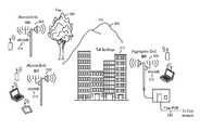
- microwave radios 132for backhaul have been mounted on high towers 112 (or high rooftops of multi-story buildings) as shown in FIG. 1 , such that each microwave radio 132 has an unobstructed line of sight (LOS) 136 to the other.
- LOSline of sight
- These microwave radios 132can have data rates of 100 Mb/s or higher at unobstructed LOS ranges of 300 m or longer with latencies of 5 ms or less (to minimize overall network latency).
- Traditional microwave backhaul radios 132operate in a Point to Point (PTP) configuration using a single “high gain” (typically >30 dBi or even >40 dBi) antenna at each end of the link 136 , such as, for example, antennas constructed using a parabolic dish.
- high gain antennasmitigate the effects of unwanted multipath self-interference or unwanted co-channel interference from other radio systems such that high data rates, long range and low latency can be achieved.
- These high gain antennashowever have narrow radiation patterns.
- microwave backhaul radios 132require very precise, and usually manual, physical alignment of their narrow radiation patterns in order to achieve such high performance results. Such alignment is almost impossible to maintain over extended periods of time unless the two radios have a clear unobstructed line of sight (LOS) between them over the entire range of separation. Furthermore, such precise alignment makes it impractical for any one such microwave backhaul radio to communicate effectively with multiple other radios simultaneously (i.e., a “point to multipoint” (PMP) configuration).
- PMPpoint to multipoint
- “street level” deployment of cellular base stations, WLAN access points or LAN gatewayssuffers from problems because there are significant obstructions for LOS in urban environments (e.g., tall buildings, or any environments where tall trees or uneven topography are present).
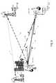
- FIG. 1illustrates edge access using conventional unobstructed LOS PTP microwave radios 132 .
- the scenario depicted in FIG. 1is common for many 2 nd Generation (2G) and 3 rd Generation (3G) cellular network deployments using “macrocells”.
- a Cellular Base Transceiver Station (BTS) 104is shown housed within a small building 108 adjacent to a large tower 112 .
- the cellular antennas 116 that communicate with various cellular subscriber devices 120are mounted on the towers 112 .
- the PTP microwave radios 132are mounted on the towers 112 and are connected to the BTSs 104 via an nT1 interface. As shown in FIG. 1 by line 136 , the radios 132 require unobstructed LOS.
- the BTS on the right 104 ahas either an nT1 copper interface or an optical fiber interface 124 to connect the BTS 104 a to the Base Station Controller (BSC) 128 .
- the BSC 128either is part of or communicates with the core network of the cellular network operator.
- the BTS on the left 104 bis identical to the BTS on the right 104 a in FIG. 1 except that the BTS on the left 104 b has no local wireline nT1 (or optical fiber equivalent) so the nT1 interface is instead connected to a conventional PTP microwave radio 132 with unobstructed LOS to the tower on the right 112 a .
- the nT1 interfaces for both BTSs 104 a , 104 bcan then be backhauled to the BSC 128 as shown in FIG. 1 .
- conventional microwave backhaul radioshave used “high gain” (typically >30 dBi or even >40 dBi) to achieve desired combinations of high throughput, long range and low latency in bridging remote data networks to core networks for unobstructed line of sight (LOS) propagation conditions. Because of their very narrow antenna radiation patterns and manual alignment requirements, these conventional microwave backhaul radios are completely unsuitable for applications with remote data network backhaul in obstructed LOS conditions, such as deployment on street lamps, traffic lights, low building sides or rooftops, or any fixture where trees, buildings, hills, etc., which substantially impede radio propagation from one point to another.
- LOSline of sight
- microwave backhaul radiosare typically islands of connectivity with little or no capability to monitor the spectrum usage broadly at the deployment location or coordinate with other radios in the vicinity to optimally use spectrum resources.
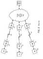
- FIG. 2illustrates an exemplary deployment of multiple conventional backhaul radios (CBRs) 132 as discrete point to point (PTP) links 204 to bridge remote data access networks (ANs) 208 to a private core network (PCN) 212 .
- CBRsbackhaul radios
- PTPpoint to point
- ANsremote data access networks
- PCNprivate core network
- Each link 204requires unobstructed LOS propagation and is limited to a single PTP radio configuration.
- the CBRs 132 at such locationrequire spatial and directional separation if co-channel operation is used.
- an EMS 216allows fault monitoring, configuration, accounting, performance monitoring and security key management (FCAPS) for the CBRs 132 within the PCN 212 .
- FCAPSperformance monitoring and security key management
- a conventional EMS 216does not dynamically modify operational policies or configurations at each CBR 132 in response to mutual interactions, changing network loads, or changes in the radio spectrum environment in the vicinity of the deployed CBRs 132 .
- an EMS 216is typically isolated from communications with or coordination amongst other EMSs at other PCNs (not shown) that may be overlapping geographically from a radio spectrum perspective.
- IBRsovercome the limitation of obstructed LOS operation and enable many desirable capabilities such as, for example only, monitoring of spectrum activity in the vicinity of the deployment and actively avoiding or mitigating co-channel interference.
- IBSIntelligent Backhaul System
- an intelligent backhaul systemthat includes a plurality of intelligent backhaul radios and a server in communication with an intelligent backhaul management system agent within at least one of the plurality of intelligent backhaul radios.
- the serveris configured to manage or control at least one of the plurality of intelligent backhaul radios.
- the IBRs and the IBScan be utilized to aid in the determination, deployment and management of IBR operational parameters in the same bands of operation as existing CBRs or other radios to which or from which interference is undesirable or forbidden (e.g., within specific 47 C.F.R. ⁇ 101 licensed bands).
- such deploymentmay include co-channel operation with CBRs or other systems including particularly within specific 47 C.F.R. ⁇ 101 licensed bands systems, such as Common Carrier Fixed Point to Point Microwave Service and Private Operational Fixed Point-to-Point Microwave Service and associated bands.
- Information stored within or obtained by the IBS or other network elementscan be used to determine or aid in the determination of IBR operational parameters that allow co-band or co-channel operation with manageable interference impact to and from CBRs or other services within a geographic zone, or within a known radio frequency propagation distance.
- Exemplary IBR operational parametersinclude but are not limited to: the selection operational frequencies; the modification of transmitter antenna patterns; the modifying or selection of antenna polarization or spatial patterns; the selection of specific antennas from a set of available antennas; the selection of transmission nulls reducing the interference impinging upon other systems; the selection of receive or transmission digital beam forming weights, or algorithmic beam forming constraints; the physical movement, placement, alignment, or augmentation of one or more antenna elements, or antenna arrays by electrical, or electromechanical control or by a request for manual adjustment or augmentation during or after installation; and the modification of transmission power; and the selection of interference margin values for the reduction of the risk in interfering existing systems.
- the determination of the IBR operational parametersis performed utilizing an algorithm based at least in part on known CBR locations and radiation parameters that are stored, for example, in the Universal Licensing System (ULS) operated by the Federal Communications Commission (FCC), or in other public or private databases.
- ULSUniversal Licensing System
- FCCFederal Communications Commission
- ULS information and associated radiation parametersin combination with radio frequency propagation models are utilized to determine the level to which operation of an IBR under various IBR operational parameters would interfere with one or more licensed 47 C.F.R. ⁇ 101 services, including Common Carrier Fixed Point to Point Microwave Service and Private Operational Fixed Point-to-Point Microwave Service within designated bands.
- reports of received signalsare provided by the IBRs, optionally in combination with existing IBR operational parameters, to the Intelligent Backhaul Radio Management System (IBMS) for use in IBR operational parameter determination.
- IBMSIntelligent Backhaul Radio Management System
- reportsmay be stored by the IBMS and used alone or in combination with CBR radiation parameter information from public or private databases to perform IBR operational parameter selection.
- Further embodimentsmay include an iterative method.
- the IBRsmay report received spectral measurements and configuration parameters to the IBMS, which performs selection of some or all for the operation parameters, and passes said parameters to respective IBRs.
- the IBRsmay then perform additional or refined scanning, or initial operation, prior to the determination of the IBR operational parameters.
- a remote end IBRis configured to operate with an aggregation end IBR (AE-IBR) on one or more frequency channels which are co-channel with a time division duplexed (TDD) CBR.
- the AE-IBRhas a wired Ethernet connection to the IMBS.
- the RE-IBRconnects to the IBMS utilizing an out of band data link in the form of a cellular data link during configuration, which may be a mobile phone having a Wi-Fi connection to the RE-IBR (i.e., the phone is acting as a mobile hot spot) or utilizing a Wi-Fi direct connection.
- the respective IBRsUpon initiating the configuration process, the respective IBRs perform a scan of their receive channels to detect existing CBRs. The IBRs then report their respective antenna configurations and scan results to the IBMS.
- the IMBSdetermines, assuming another channel may not be used, the level of interference the CBR will receive. The interference is determined utilizing IBR effective antenna pattern adjustments and, optionally, associated information retrieved from a database of CBR parameters.
- the effective antenna pattern adjustmentincludes the use of a transmission beam nulling from the required one or more IBRs to further reduce the interference levels which may be received at the CBR, while maintaining a minimum required performance between the respective IBRs. In some embodiments, an interference margin is calculated.
- the interference margincan be used as an additional reduction of the required interference to the target CBR.
- the interference marginmay be based on a fixed amount, a level of uncertainty of the predicted interference, an amount based upon the reliability or predicted accuracy of interference calculations, or based upon using or the availability of or specific values of CBR antenna and operating transmission parameters retrieved from a database.
- the RE-IBRs and AE-IBRsmay operate on channels for which no interference is detected, but are within a predetermined distance of a CBR.
- the distancemay be determined based on the geographic location of each IBR and the CBR (e.g., the location of the CBR determined by accessing the FCC ULS database).
- an interference margin value, or other operational constraint valuemay be utilized by the IBMS based upon propagation models to further reduce the likelihood of interfering with the CBR.
- co-existence of IBRs with FDD (frequency division duplex) CBRsmay be required.
- interference margins or operational transmission constraintsmay be calculated.
- An exemplary constraintis transmission beam nulling. In this example, during a scan procedure, the values related to transmission beam nulling may be determined.
- received signals transmitted from a CBR operating in FDDare detected during a scan procedure at an IBR.
- the IBR to IBR linkin one deployment, is configured to operate on the specific FDD paired frequency channel used for receiving by the FDD CBR as determined by the IMBS and FCC database records.
- transmission beam nulling weights or constraintsmay be determined based upon the received signals in the paired channel, despite the frequency difference for the transmission channel.
- Such calculationsmay utilize propagation modeling to determine interference levels, reported measurements by the IBR to determine the level of frequency flat fading, and database values related to CBR parameters. These calculations involve a constrained transmission beam forming calculation. For example, an interference margin may be included based at least in part upon the determined level of flat fading of the scanned signal on the paired band.
- an intelligent backhaul radioincludes a plurality of receive RF chains; one or more transmit RF chains; an antenna array comprising a plurality of directive gain antenna elements, wherein each directive gain antenna element is couplable to at least one receive RF or transmit RF chain; and an interface bridge configured to couple the intelligent backhaul radio to a data network, the interface bridge comprising one or more Ethernet interfaces to couple the interface bridge to the data network, wherein the intelligent backhaul radio is configured to scan a plurality of radio frequency channels for the presence of radio signals transmitted from one or more point to point microwave systems to generate scan data, and wherein the intelligent backhaul radio comprises at least one adjustable network parameter that is adjustable based on the scan data, wherein the at least one network parameter is adjusted to reduce a potential of interference of the intelligent backhaul radio with the one or more point to point microwave systems, wherein the intelligent backhaul radio is a first intelligent backhaul radio, and wherein the adjusting the at least one network parameter comprises one or more of: selecting
- the intelligent backhaul radiomay include an intelligent backhaul controller.
- the intelligent backhaul radiomay include an intelligent backhaul management system agent.
- the intelligent backhaul radiomay include a wireless adapter.
- the intelligent backhaul radiomay be further configured to generate a scan report based on the scan data and transmit the scan report to a server.
- the signalsmay include a signal licensed by the Federal Communications Commission (FCC) under 47 Code of Federal Regulations (CFR) section 101 as a common carrier fixed point-to-point microwave service or as a private operational fixed point-to-point microwave service.
- FCCFederal Communications Commission
- CFRCode of Federal Regulations
- Adjusting the effective radiation patternmay include one or more of: steering the effective radiation pattern in elevation; and steering the effective radiation pattern in azimuth.
- Adjusting the effective radiation patternmay include calculating digital beam former weights based upon at least one constraint related to the potential of interference; and applying the digital beam former weights.
- the constraintmay be selected from the group consisting of: properties related to or derived from said scan result; a direction in which signal transmission is to be limited; parameters which reduce the potential for interfering with said one or more point to point microwave systems; parameters which increase the likelihood of said first and said second internet backhaul radios meeting performance goals with respect to an interposed wireless communication link; a restriction of use of specific transceivers or specific antennas of a plurality of transceivers or antennas; a use of specific polarizations for transmission; attributes of a collective transmission radiation pattern associated with a plurality of transmitters; a frequency or geometric translation of beam forming weights between receiver weights and transmitter weights; based upon a change in antennas used or selected; based upon a change in operating frequency; and combinations thereof.
- the scan reportmay include one more selected from the group consisting of: the location of said first IBR; the latitude and longitudinal coordinates of one or more IBRs; configuration information related to the first IBR; capability information related to the first IBR; a transmission power capability of said first IBR; operating frequency capability of said first IBR; antenna property information related to one or more antenna for use in reception or transmission by said first IBR; received signal parameters or demodulated information from another internet backhaul radio; received signal parameters from a received point to point microwave system; and combinations thereof.
- the intelligent backhaul radiomay be further configured to assess performance after adjustment of the at least one adjustable network parameter.
- the intelligent backhaul radiomay be a first intelligent backhaul radio, and the performance may be assessed by one or more selected from the group consisting of: performing additional scans; performing additional scans with specific search criteria; performing additional scans with limitations in frequency, azimuth, elevation, or time; performing additional scans with a modified antenna selection configuration; performing additional scans using antennas intended for transmission during normal operation for reception during the additional scanning process; performing transmission of a signal from the first intelligent backhaul radio to a second intelligent backhaul radio, receiving a signal from the second intelligent backhaul radio by the first intelligent backhaul radio.
- the intelligent backhaul radiomay be a first intelligent backhaul radio, and the first intelligent backhaul radio may be configured to align the antenna array with a second intelligent backhaul radio prior to the scan based on at least one criterion.
- the at least one criterionmay be based at least in part upon a signal transmitted from the second intelligent backhaul radio.
- the at least one criterionmay include a GPS location and a compass direction.
- an intelligent backhaul systemincludes an intelligent backhaul radio having a plurality of receive RF chains; one or more transmit RF chains; an antenna array comprising a plurality of directive gain antenna elements, wherein each directive gain antenna element is couplable to at least one receive RF or transmit RF chain; and an interface bridge configured to couple the intelligent backhaul radio to a data network, the interface bridge comprising one or more Ethernet interfaces to couple the interface bridge to the data network, wherein the intelligent backhaul radio is configured to scan a plurality of radio frequency channels for the presence of radio signals transmitted from one or more point to point microwave systems to generate scan data, and wherein the intelligent backhaul radio comprises at least one adjustable network parameter that is adjustable based on the scan data; and a server in communication with the intelligent backhaul radio, wherein the server is configured to receive the scan data from the intelligent backhaul radio, wherein the at least one network parameter is adjusted to reduce the potential of interference of the intelligent backhaul radio with the one or more point to point microwave systems
- the servermay be configured to store data received from the intelligent backhaul radio.
- the systemmay further include one or more intelligent backhaul controllers.
- the intelligent backhaul radiomay include an intelligent backhaul controller.
- the intelligent backhaul radiomay include an intelligent backhaul management system agent.
- the servermay be at least one of a private server and a global server.
- the intelligent backhaul radiomay include a wireless adapter.
- the intelligent backhaul radiomay be further configured to generate a scan report based on the scan data, and wherein the server is configured to receive the scan report.
- the servermay utilize the scan data to identify the at least one network parameter to be adjusted.
- the signalsmay include a signal licensed by the Federal Communications Commission (FCC) under 47 Code of Federal Regulations (CFR) section 101 as a common carrier fixed point-to-point microwave service or as a private operational fixed point-to-point microwave service.
- FCCFederal Communications Commission
- CFRCode of Federal Regulations
- the scan datamay be analyzed by the server to determine a potential of interference of the intelligent backhaul radio with the one or more point to point microwave systems.
- the servermay perform a mathematical modeling of the radio propagation of one or more potentially interfering signals from the intelligent backhaul radio to the one or more point to point microwave systems.
- Adjusting the effective radiation patternmay include one or more of: steering the effective radiation pattern in elevation; and steering the effective radiation pattern in azimuth.
- Adjusting the effective radiation patternmay include calculating digital beam former weights based upon at least one constraint related to the potential of interference; and applying the digital beam former weights.
- the constraintmay be selected from the group consisting of: properties related to or derived from said scan result; a direction in which signal transmission is to be limited; parameters which reduce the potential for interfering with said one or more point to point microwave systems; parameters which increase the likelihood of said first and said second internet backhaul radios meeting performance goals with respect to an interposed wireless communication link; a restriction of use of specific transceivers or specific antennas of a plurality of transceivers or antennas; a use of specific polarizations for transmission; attributes of a collective transmission radiation pattern associated with a plurality of transmitters; a frequency or geometric translation of beam forming weights between receiver weights and transmitter weights; based upon a change in antennas used or selected; based upon a change in operating frequency; and combinations thereof.
- the mathematical modelingmay be based on the scan data.
- the scan reportmay include one more selected from the group consisting of: the location of said first IBR; the latitude and longitudinal coordinates of one or more IBRs; configuration information related to the first IBR; capability information related to the first IBR; a transmission power capability of said first IBR; operating frequency capability of said first IBR; antenna property information related to one or more antenna for use in reception or transmission by said first IBR; received signal parameters, or demodulated information from another internet backhaul radio; received signal parameters from a received point to point microwave system; and combinations thereof.
- the intelligent backhaul radiomay be further configured to assess performance after adjustment of the at least one adjustable network parameter.
- the intelligent backhaul radiomay be a first intelligent backhaul radio, and the performance may be assessed by one or more selected from the group consisting of: performing additional scans; performing additional scans with specific search criteria; performing additional scans with limitations in frequency, azimuth, elevation, or time; performing additional scans with a modified antenna selection configuration; performing additional scans using antennas intended for transmission during normal operation for reception during the additional scanning process; performing transmission of a signal from the first intelligent backhaul radio to a second intelligent backhaul radio; receiving a signal from the second intelligent backhaul radio by the first intelligent backhaul radio.
- the intelligent backhaul radiomay be a first intelligent backhaul radio, and the first intelligent backhaul radio may be configured to align the antenna array with a second intelligent backhaul radio prior to the scan based on at least one criterion.
- the at least one criterionmay be based at least in part upon a signal transmitted from the second intelligent backhaul radio.
- the at least one criterionmay include a GPS location and a compass direction.
- the systemmay further include an installation assisting device, and the installation assisting device may determine the GPS location and the compass direction.
- the servermay be coupled with a database, and the database may include information related to one or more existing point to point microwave sites.
- the informationmay include one or more selected from the group consisting of: radio service group; fixed transmit location details; latitude and longitude of one or more existing point to point microwave sites; street address of one or more existing point to point microwave sites; site elevation; antenna elevation; transmitter antenna height; polarization; beam width; antenna pointing azimuth and elevation angle; antenna gain; transmitter power or equivalent isotropically radiated power (EIRP); frequency of operation or frequency tolerance; emission designator; equipment modulation type and rate; and equipment manufacturer.
- EIRPisotropically radiated power
- FIG. 1is an illustration of conventional point to point (PTP) radios deployed for cellular base station backhaul with unobstructed line of sight (LOS).
- PTPpoint to point
- LOSline of sight
- FIG. 2is an illustration of an exemplary deployment of conventional backhaul radios.
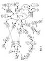
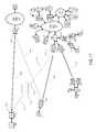
- FIG. 3is an illustration of intelligent backhaul radios (IBRs) deployed for cellular base station backhaul with obstructed LOS according to one embodiment of the invention.
- IBRsintelligent backhaul radios
- FIG. 4is an exemplary deployment of an intelligent backhaul system (IBS) according to one embodiment of the invention.
- IBSintelligent backhaul system
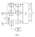
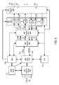
- FIG. 5is a block diagram of an IBR according to one embodiment of the invention.
- FIG. 6is a block diagram of an IBR according to one embodiment of the invention.
- FIG. 7is a block diagram of an intelligent backhaul controller (IBC) according to one embodiment of the invention.
- IBCintelligent backhaul controller
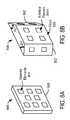
- FIG. 8Ais a perspective view of an IBR including antenna array geometry according to one embodiment of the invention.
- FIG. 8Bis a perspective view of an IBR including antenna array geometry according to one embodiment of the invention.
- FIG. 9illustrates exemplary deployment of intelligent backhaul radios (IBRs) deployed for cellular base station backhaul with obstructed LOS in the presence of an existing exemplary deployment of conventional backhaul radios deployed for cellular base station backhaul with unobstructed line of sight (LOS) according to one embodiment of the invention.
- IBRsintelligent backhaul radios
- FIG. 10illustrates an exemplary deployment of intelligent backhaul radios (IBRs) deployed for cellular base station backhaul with obstructed LOS in the presence of an existing exemplary deployment of conventional backhaul radios deployed for cellular base station backhaul with unobstructed line of sight (LOS) according to one embodiment of the invention.
- IBRsintelligent backhaul radios
- FIG. 11illustrates an exemplary deployment of an intelligent backhaul system (MS) in the presence of an existing exemplary deployment of conventional backhaul radios according to one embodiment of the invention.
- MSintelligent backhaul system
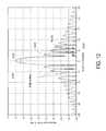
- FIG. 12illustrates a normalized antenna gain relative to an angle from bore utilizing an exemplary antenna system.
- FIG. 13Ais a table of a partial listing for the frequency availability for specific radio services 47 C.F.R. ⁇ 101.101.
- FIG. 13Billustrates an exemplary deployment for occupancy of services in the 3700 to 4200 MHZ frequency band for conventional cellular backhaul radios or other services as licensed under 47 C.F.R. ⁇ 101 and listed in the FCC Universal Licensing System.
- FIG. 14is a flow chart illustrating an IBR installation process according to one embodiment of the present invention.
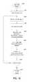
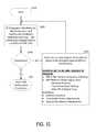
- FIG. 15is a flow chart illustrating selection of IBR configuration parameters according to one embodiment of the present invention.
- FIG. 3illustrates deployment of intelligent backhaul radios (IBRs) in accordance with an embodiment of the invention.
- the IBRs 300are deployable at street level with obstructions such as trees 304 , hills 308 , buildings 312 , etc. between them.
- the IBRs 300are also deployable in configurations that include point to multipoint (PMP), as shown in FIG. 3 , as well as point to point (PTP).
- PMPpoint to multipoint
- PTPpoint to point
- each IBR 300may communicate with one or more than one other IBR 300 .
- cellular network infrastructureis more commonly deployed using “microcells” or “picocells.”
- compact base stations (eNodeBs) 316are situated outdoors at street level. When such eNodeBs 316 are unable to connect locally to optical fiber or a copper wireline of sufficient data bandwidth, then a wireless connection to a fiber “point of presence” (POP) requires obstructed LOS capabilities, as described herein.
- POPpoint of presence
- the IBRs 300include an Aggregation End IBR (AE-IBR) and Remote End IBRs (RE-IBRs).
- AE-IBRAggregation End IBR
- RE-IBRsRemote End IBRs
- the eNodeB 316 of the AE-IBRis typically connected locally to the core network via a fiber POP 320 .
- the RE-IBRs and their associated eNodeBs 316are typically not connected to the core network via a wireline connection; instead, the RE-IBRs are wirelessly connected to the core network via the AE-IBR.
- the wireless connection between the IBRsinclude obstructions (i.e., there may be an obstructed LOS connection between the RE-IBRs and the AE-IBR).
- FIG. 4illustrates an exemplary deployment of an intelligent backhaul system (IBS) 400 .
- the IBS 400includes multiple IBRs 404 that can operate in both obstructed and unobstructed LOS propagation conditions.
- the IBS 400has several features that are not typical for conventional line of sight microwave backhaul systems.
- the IBS 400includes multiple IBRs 404 .
- Exemplary IBRsare shown and described below with reference to, for example, FIG. 5 of the present application, and are disclosed in detail in co-pending U.S. patent application Ser. No. 13/212,036, entitled Intelligent Backhaul Radio, filed Aug. 17, 2011, and FIG. 4 of co-pending U.S. patent application Ser. No. 13/271,051, entitled Intelligent Backhaul System, filed Oct. 11, 2011, the entireties of which is hereby incorporated by reference. It will be appreciated that there are many possible embodiments for the IBRs as described herein and in co-pending U.S. patent application Ser. Nos. 13/212,036 and 13/271,051.
- the IBRs 404are able to function in both obstructed and unobstructed LOS propagation conditions.
- the IBS 400optionally, includes one or more “Intelligent Backhaul Controllers” (IBCs) 408 .
- IBCsIntelligent Backhaul Controllers
- the IBCs 408are deployed between the IBRs 404 and other network elements, such as remote data access networks (ANs) 412 and a private core network (PCN) 416 .
- ANsremote data access networks
- PCNprivate core network
- the IBS 400includes an “Intelligent Backhaul Management System” (IBMS) 420 .
- the IBMS 420includes a private server 424 and/or a public server 428 .
- the IBMS 420may also include an IBMS agent in one or more of the IBRs 404 .
- the IBMS agentis described in detail with reference to FIG. 5 of the present application, FIG. 5 of and copending U.S. application Ser. No. 13/271,051 and FIG. 7 of copending U.S. application Ser. No. 13/212,036.
- An IBMS agentmay, optionally, be included within one or more of the IBCs 408 .
- FIG. 5is a simplified block diagram of the IBRs 404 shown in FIG. 4 .
- the IBRs 404include interfaces 504 , interface bridge 508 , MAC 512 , a physical layer 516 , antenna array 548 (includes multiple antennas 552 ), a Radio Link Controller (RLC) 556 and a Radio Resource Controller (RRC) 560 .
- the IBRmay optionally include an IBMS agent 572 .
- FIG. 5illustrates, in particular, an exemplary embodiment for powering the IBR 404 .
- the IBR 404also includes a Power Supply 576 and an optional Battery Backup 580 .
- the Power Supply 576may receive a Power Input 584 or an alternative power input derived from a network interface 504 . It will be appreciated that the components and elements of the IBRs may vary from that illustrated in FIG. 5 .
- the IBR Interface Bridge 508physically interfaces to standards-based wired data networking interfaces 504 as Ethernet 1 through Ethernet P. “P” represents a number of separate Ethernet interfaces over twisted-pair, coax or optical fiber.
- the IBR Interface Bridge 508can multiplex and buffer the P Ethernet interfaces 504 with the IBR MAC 512 .
- the IBR Interface Bridge 508may also include an optional IEEE 802.11 (or WiFi) adapter.
- IBR Interface Bridge 508also preserves “Quality of Service” (QoS) or “Class of Service” (CoS) prioritization as indicated, for example, in IEEE 802.1q 3-bit Priority Code Point (PCP) fields within the Ethernet frame headers, such that either the IBR MAC 512 schedules such frames for transmission according to policies configured within the IBR of FIG. 5 or communicated via the IBMS Agent 572 , or the IBR interface bridge 508 schedules the transfer of such frames to the IBR MAC 512 such that the same net effect occurs.
- the IBR interface bridge 508also forwards and prioritizes the delivery of frames to or from another IBR over an instant radio link based on Multiprotocol Label Switching (MPLS) or Multiprotocol Label Switching Transport Profile (MPLS-TP).
- MPLSMultiprotocol Label Switching
- MPLS-TPMultiprotocol Label Switching Transport Profile
- the IBRutilizes multiple antennas and transmit and/or receive chains which can be utilized advantageously by several well-known baseband signal processing techniques that exploit multipath broadband channel propagation.
- Such techniquesinclude Multiple-Input, Multiple-Output (MIMO), MIMO Spatial Multiplexing (MIMO-SM), beam forming (BF), maximal ratio combining (MRC), and Space Division Multiple Access (SDMA).
- MIMOMultiple-Input, Multiple-Output
- MIMO-SMMIMO Spatial Multiplexing
- BFbeam forming
- MRCmaximal ratio combining
- SDMASpace Division Multiple Access
- the Intelligent Backhaul Management System (IBMS) Agent 572is an optional element of the IBR that optimizes performance of the instant links at the IBR as well as potentially other IBR links in the nearby geographic proximity including potential future links for IBRs yet to be deployed.
- FIG. 6illustrates an exemplary detailed embodiment of the IBR 400 illustrating some additional details.
- FIG. 6corresponds to FIG. 7 of copending U.S. application Ser. No. 13/212,036 and FIG. 6 of copending U.S. application Ser. No. 13/271,051.
- the IBR 400includes interfaces 604 , interface bridge 608 , media access controller (MAC) 612 , modem 624 , which includes one or more demodulator cores and modulator cores, channel multiplexer (MUX) 628 , RF 632, which includes transmit chains (Tx 1 . . . TxM) 636 and receive chains (Rx 1 . . .
- MACmedia access controller
- modem 624which includes one or more demodulator cores and modulator cores
- MUXchannel multiplexer
- RF 632which includes transmit chains (Tx 1 . . . TxM) 636 and receive chains (Rx 1 . . .
- RxN640
- antenna array 648(includes multiple directive gain antennas/antenna elements 652 ), a Radio Link Controller (RLC) 656 , a Radio Resource Controller (RRC) 660 and the IBMS agent 572 .
- RLCRadio Link Controller
- RRCRadio Resource Controller
- IBMS agent 572IBMS agent
- the primary responsibility of the RRC 660is to set or cause to be set at least the one or more active RF carrier frequencies, the one or more active channel bandwidths, the choice of transmit and receive channel equalization and multiplexing strategies, the configuration and assignment of one or more modulated streams amongst the one or more modulator cores, the number of active transmit and receive RF chains, and the selection of certain antenna elements and their mappings to the various RF chains.
- the RRC 660may also set or cause to be set the superframe timing, the cyclic prefix length, and/or the criteria by which blocks of Training Pilots are inserted.
- the RRC 660allocates portions of the IBR operational resources, including time multiplexing of currently selected resources, to the task of testing certain links between an AE-IBR and one or more RE-IBRs.
- the MAC 612exchanges data to and from a remote access data network via coupling to at least the interface bridge 608 and to and from at least one other intelligent backhaul radio.
- the MAC 612inputs receive data from a receive path and outputs transmit data to the transmit path.
- the various policies and configuration parameters used by the RRC 660 to allocate resources within and amongst IBRs with active links to each otherare sent from the IBMS Agent 572 to the RRC 660 .
- the RRC 660reports operational statistics and parameters back to the IBMS Agent 572 both from normal operation modes and from “probe in space” modes as directed by the IBMS Agent 572 .
- the IBR 400also includes a power supply 576 .
- a Power Input 584 to the Power Supply 576is an alternating current (AC) supply of, for example, 120V, 60 Hz or 240V, 50 Hz or 480V, 60 Hz, 3-phase.
- the Power Input 584may be a direct current (DC) supply of, for example, +24V, ⁇ 48V, or ⁇ 54V.
- the Power Supply 576outputs voltage to other elements of the IBR 404 .
- typical Power Supply 576 output voltagesare DC voltages such as +12V, +5V, +3.3V, +1.8V, +1.2V, +1.0V or ⁇ 1.5V.
- the Battery Backup 580may provide an alternative power input to the Power Supply 576 so that IBR operation may continue for some period of time. This is particularly advantageous for ANs at remote locations wherein critical communications services may be needed during temporary main power supply outages.
- the Battery Backup 580is typically charged by a DC input such as +18V or +12V from the Power Supply 576 .
- the Power Supply 576may optionally receive a power input derived from a network interface 504 .
- a power input from a network interface 504is “Power over Ethernet” (or PoE) as defined by IEEE 802.af.
- an exemplary power input from a network interface 504is “Power over Ethernet Plus” (or PoE+) as defined by IEEE 802.at.
- Typical DC voltages associated with POEare +48V or ⁇ 48V, and typical DC voltages associated with PoE+ are +54V or ⁇ 54V.
- the Power Supply 576may be desirable for the Power Supply 576 to operate from AC main supplies, such as 120V, 240V or 480V, in two separate structures.
- an AC to DC convertercreates a DC power input such as +24V, +12V, +18V, ⁇ 48V, ⁇ 54V, etc; and, second, a DC to DC converter creates the DC voltages required internal to the IBR such as +12V, +5V, +3.3V, +1.8V, +1.2V, +1.0V, ⁇ 1.5V, etc.
- the AC to DC converter portion of the Power Supply 576may be physically external to the main enclosure of the IBR while the DC to DC converter portion of the Power Supply 576 is internal to the main enclosure of the IBR.
- the Battery Backup 580may be external to the main enclosure of the IBR.
- the WiFi Adaptermay be positioned internal to or external of the enclosure of the IBR.
- the IBMS Agent shown in FIG. 5can function as described in copending U.S. application Ser. No. 13/212,036, copending U.S. application Ser. No. 13/271,051 and/or as described in more detail below.
- the Power Supply 576may provide a control signal (Power Status) 592 to the IBMS Agent 572 that communicates, for example, if the Power Supply 576 is operating from a Power Input 584 , a derived power input from a network interface 588 , or from an optional Battery Backup 580 and possibly an estimated current reserve level for such Battery Backup.
- the IBMS Agent 572may relay this status 592 to other elements of the IBS 400 .
- FIG. 7illustrates a simplified block diagram of IBCs 408 A-C of FIG. 4 .
- the IBC 408includes a plurality of physical layer ports 704 that include a plurality of network interfaces 708 .
- the IBC 408also includes a wireless adapter 712 , an IBC managed switch 716 , a remote power switch 720 , an IBMS agent 724 , and an IBC host controller 728 .
- the IBC 408may also include a power supply 732 and an optional battery backup 736 .
- the plurality of Network Interfaces 708are typically an Ethernet or IEEE 802.3 interfaces based on copper wires or fiber optics. Typically, such Ethernet interfaces support data rates of 1 Gb/s, 10 Gb/s or higher.
- Each Network Interface 708is typically coupled to a respective Physical Layer Port 704 and in turn typically coupled to a respective Layer 2 port within the IBC Managed Switch 716 .
- the IBC Managed Switch 716is a substantially conventional Layer 2 switch in accordance with standard features defined by various IEEE 802.1 and 802.2 specifications.
- the IBC Managed Switch 716may be compliant with IEEE 802.1D for MAC-layer bridging across various ports and IEEE 802.1Q for adding Virtual Local Area Networking (VLAN) tags and the 3-bit 802.1p Priority Code Point (PCP) field.
- VLAN capabilityenables the IBC Managed Switch 716 to be segmented amongst certain subsets of the available switch ports and the PCP fields enable certain frames to have higher delivery priority than other frames.
- IBC Managed Switch 716 capabilitiesinclude compliance with IEEE 802.1X for access control, IEEE 802.1AB for link layer discovery, IEEE 802.1AE for MAC layer security, and IEEE 802.1AX for link aggregation and resiliency as well as numerous derivative standards specifications based on the above list (and IEEE 802.1D and 802.1Q).
- the IBC Managed Switch 716may also have certain routing or packet-forwarding capabilities, such as routing by Internet Protocol (IP) address or packet-forwarding by Multiprotocol Label Switching (MPLS) in a substantially conventional fashion.
- IPInternet Protocol
- MPLSMultiprotocol Label Switching
- some IBC Managed Switches 716may operate as an MPLS Label Switch Router (LSR) while other MPLS-compatible devices within certain ANs operate as Label Edge Routers (LERs that represent ingress and egress points for packets within an MPLS network).
- LSRMPLS Label Switch Router
- LERsLabel Edge Routers
- the IBC Managed Switch 716may alternatively or additionally operate as an LER that affixes or removes MPLS labels having at least a label value or identifier, a 3-bit traffic class field (analogous to the PCP filed in IEEE 802.1 or the precedence bits in the Type of Service field in IP headers), and a time-to live field. Based on MPLS labels, such IBC Managed Switches 716 forward packets to particular ports (or possibly sets of ports in a VLAN segment) corresponding to certain ANs or IBRs as associated with particular “tunnels” to other MPLS LERs or LSRs, or based on MPLS ingress or egress ports from the IBC Managed Switch 716 when operating as an MPLS LER.
- the IBC Managed Switch 716may alternatively or additionally operate as an MPLS Transport Profile (MPLS-TP) switch to provide connection-oriented, packet-switching on specific paths between such an IBC and typically another such IBC or peer MPLS-TP device at the edge of the PCN 416 .
- MPLS-TPMPLS Transport Profile
- the IBC Managed Switch 716may alternatively or additionally operate as a Carrier Ethernet switch that provides one or more Ethernet Virtual Connections (EVCs) according to standards promulgated by the Metro Ethernet Forum (MEF).
- EVCsEthernet Virtual Connections
- certain IBC Network Interface 708 portsmay be configured within the IBC Managed Switch 716 as an MEF User Network Interface (UNI) port.
- UNIUser Network Interface
- such an IBC UNI portif associated with an AN 412 at an IBC 408 on a remote location, can then be paired to another UNI (possibly at another IBC) at the edge of the PCN (at an aggregation point) via an EVC.
- the EVCcould be an E-Line such as an Ethernet Private Line, an E-LAN such as an Ethernet Private LAN, or an E-Tree.
- an exemplary IBC 408 with MEF capabilitycan also interact with one or more IBR-based links to provide Committed Information Rate (CIR) and Excess Information Rate (EIR). These interactions may be direct via one or more Network Interfaces 708 or optionally indirect via the IBMS 420 .
- CIRCommitted Information Rate
- EIRExcess Information Rate
- the IBC 408may also include an IBC Host Controller 728 .
- the IBC host controller 728may be implemented as software on one or more microprocessors.
- the IBC Host Controller 728directs the operation of the IBC Managed Switch 716 according to policies provided to the IBC 408 .
- the scope of policies applicable to a given IBC 408depends on the particular set of IBC Managed Switch capabilities, as described above. Typical policies relate to the mapping between Network Interface 708 ports assigned to ANs 412 and those assigned to IBRs 404 as realized within the IBC Managed Switch 716 .
- the policiesmay be derived from Service Level Agreements (SLAs) that govern the desired and/or required performance attributes of backhaul connections between particular ANs 412 or users of ANs 412 and the PCN 416 .
- SLAsService Level Agreements
- the policies administered by the IBC Host Controller 728 in directing the behavior of the IBC Managed Switch 716are supplied by the IBMS Agent 724 . In some embodiments, such policies are alternatively or additionally supplied by a console interface to the IBC 408 at the time of initial deployment or later.
- the IBC 408may also include an IEEE 802.11 Wireless LAN interface (i.e. a “WiFi Adapter”) 712 .
- the WiFi Adapter 712may be configured as a public or private IEEE 802.11 access point based on one or more standard specifications such as IEEE802.11g, IEEE802.11n or subsequent IEEE 802.11 variants.
- the IBCeffectively integrates a WiFi-based AN within the IBC that is attached to an internal port of the IBC Managed Switch 716 such that traffic to or from the WiFi AN can be bridged to one or more IBRs 404 , or passed to an IBMS Agent 724 , 576 (at either the IBC 408 or within the one or more attached IBRs 404 ) or the IBC Host Controller 728 over standard network protocols, such as TCP or UDP on IP.
- standard network protocolssuch as TCP or UDP on IP.
- IBC Managed Switch 716This permits terminal devices such as smartphones, tablets or laptop computers to act as a console input to easily access, monitor or configure policies and performance data associated with the IBC 408 , or via the IBC Managed Switch 716 , also access, monitor or configure policies and performance data at one or more IBRs 404 attached to the IBC 408 .
- such access to the IBC 408 and attached IBRs 404can be realized via a WiFi Adapter within one of the attached IBRs 404 by bridging across an exemplary IBC 408 .
- the WiFi Adapter 712may be optionally connected to the IBC Host Controller 728 (instead of the IBC Managed Switch 716 ) over a serial bus or other internal bus suitable for peripheral I/O devices.
- the WiFi Adapter 712would not be suitable for public or private WiFi access point usage at commercially-desirable throughputs, but may still be suitable for console mode operation to access, monitor or configure policies and performance data at the IBC 408 and possibly at attached IBRs 404 to the extent permitted by the software executing on the IBC Host Controller 728 .
- the optional WiFi Adapter 712may be physically contained within the enclosure of the IBC 408 , subject to consideration of antenna location for effective propagation especially for elevated mounting and ground level access. In other embodiments, the optional WiFi Adapter 712 may be external to the IBC physical enclosure and either connected via an external Network Interface 708 or via an external mounting interface to the IBC Managed Switch 716 optimized specifically for an attached external WiFi Adapter.
- the WiFi Adapterconfigured as an access point, as a peer to peer station device, as a station device wherein the portable terminal (smartphone, tablet, laptop computer, etc.) is configured as an access point, or via WiFi direct.
- the IBC 408also includes a Power Supply 732 and an optional Battery Backup 736 .
- the Power Input 740 to the Power Supply 732may be an alternating current (AC) supply of, for example, 120V, 60 Hz or 240V, 50 Hz or 480V, 60 Hz, 3-phase.
- the Power Input 740may be a direct current (DC) supply of, for example, +24V, ⁇ 48V, or ⁇ 54V.
- Typical Power Supply 732 output voltages to the various elements of the IBCare DC voltages such as +12V, +5V, +3.3V, +1.8V, +1.2V, +1.0V or ⁇ 1.5V.
- the optional Battery Backup 736may be charged by a DC input, such as +18V or +12V, from the Power Supply 732 .
- a DC inputsuch as +18V or +12V
- the Battery Backup 736may provide an alternative power input to the Power Supply 732 so that IBC operation may continue for some period of time. This is particularly advantageous for ANs at remote locations wherein critical communications services may be needed during temporary main power supply outages.
- a Power Supply 732that operates from AC main supplies, such as 120V, 240V or 480V, includes two separate structures.
- the Power Supply 732includes an AC to DC converter that creates a DC power input such as +24V, +12V, +18V, ⁇ 48V, ⁇ 54V, etc.; and, second, the Power Supply 732 includes a DC to DC converter that creates the DC voltages required internal to the IBC such as +12V, +5V, +3.3V, +1.8V, +1.2V, +1.0V, ⁇ 1.5V, etc.
- the AC to DC converter portion of the Power Supply 732may be physically external to the main enclosure of the IBC 408 while the DC to DC converter portion of the Power Supply 732 remains internal to the main enclosure of the IBC 408 .
- the Battery Backup 736may be external to the main enclosure of the IBC 408 .
- the IBCs 408typically are not configured to use standards-based PoE or PoE+ as an alternate power input for powering the IBC 408 . Instead, the IBCs 408 combine a PoE or PoE+ power injection capability that can be switched to some or all of the Network Interfaces 708 from a Remote Power Switch 720 via the Physical Layer Ports 704 .
- the Network Interface Power Input 744such as +48V or ⁇ 48V for PoE or +54V or ⁇ 54V for PoE+, is provided by the Power Supply 732 and then switched under the direction of the IBC Host Controller 728 at the Remote Power Switch 720 .
- the specific Network Interface 408 ports receiving PoE or PoE+ power from the Remote Power Switch 720are determined based on configuration parameters set at time of deployment by, for example, console mode input or the IBMS Agent 724 or updated from time to time via the IBMS Agent 724 .
- exemplary IBCs 408may also have the Power Supply 732 provide a control signal (Power Status) 748 to at least the IBMS Agent 724 or the IBC Host Controller 728 that communicates, for example, if the Power Supply 732 is operating from a Power Input 740 or from an optional Battery Backup 736 and possibly an estimate current reserve level for such Battery Backup 736 .
- Power Status 748may be relayed by the IBMS Agent 724 to other IBMS elements.
- the IBMS Agent 724 and/or IBC Host Controller 728may choose to restrict or terminate PoE or PoE+ power to certain Network Interfaces 708 , whether AN 412 or IBR 404 , based on policies as may currently be set at the IBC 408 . Such restrictions or terminations may also consider the actual power consumption of particular Network Interfaces 708 as may be determined by the Remote Power Switch 720 and reported to the IBC Host Controller 728 .
- One example of when it is advantageous to terminate PoE or PoE+ power under backup conditionsis when the device, powered by the IBC 408 , such as an AN 412 or IBR 404 , are known to the IBC 408 (possibly via the IBMS) to have their own back-up power sources.
- the IBCs 408may also provide synchronization capabilities to ANs 412 , IBRs 404 or other network devices attached to the Network Interfaces 708 .
- One methodology for providing synchronization at remote locationssuch as IBCs 408 A or 408 C in FIG. 4 is to attach or embed a Global Positioning Satellite (GPS) receiver in an IBC (not shown in FIG. 7 ) and then distribute a one pulse per second (1 PPS) output to applicable ANs 412 and IBRs 404 .
- GPSGlobal Positioning Satellite
- the GPSmay not operate effectively in the street level obstructed propagation conditions.
- An alternative approach to establishing synchronization at the IBC 408 for distribution to ANs 412 or IBRs 404is to extend a synchronization methodology already in use in the PCN 416 .
- the synchronization methodology of the IBCs 408is Synchronous Ethernet (SyncE).
- SyncESynchronous Ethernet
- the Network Interface clock frequency of a designated physical portcan be precisely applied by the IBCs 408 to any other designated Network Interface physical port. Typically, this is performed by conventional circuitry comprised within the Physical Layer Ports 704 of the IBC 408 .
- the IBC 408can ensure that the Network Interface clock frequencies at certain physical ports are all identical over time to a master clock frequency typically supplied from within the PCN 416 . This is particularly advantageous for network deployments where synchronous applications such as voice or video communications are desired to traverse multiple backhaul links as illustrated, for example, in FIG. 4 .
- the synchronization methodologyis IEEE 1588v2 or subsequent variations thereof.
- IEEE 1588v2the IBC 408 examines timestamps within certain packets (or frames) to either derive precise timing for internal or local distribution purposes or to modify such timestamps to account for delays traversing the IBC 408 or other network links or elements. Typically, this is performed by conventional circuitry comprised within the IBC Managed Switch 716 and/or Physical Layer Ports 704 .
- IBRs 404can also include circuitry for SyncE or IEEE 1588v2 synchronization methodologies.
- the IBC 408can only pass SyncE clock frequency synchronization from a master clock in the PCN 416 to remote ANs 412 over IBR links to the extent that the IBRs 404 include SyncE capability.
- the IBRs 404operate across an instant AE-IBR to RE-IBR link as an IEEE 1588v2 transparent clock wherein the time stamp at ingress to such a link (for example, at IBR 404 F in FIG. 4 ) is modified at egress from the link (for example, at IBR 404 E in FIG. 4 ) to account for the actual latency incurred in traversing the link.
- the IBC 408operates as an IEEE 1588v2 transparent clock that modifies timestamps to account for actual latency incurred as a packet traverses from one IBC Network Interface physical port to another.
- the IBC 408alternatively or additionally operates as an IEEE 1588v2 boundary clock that has the ability to determine latency between such an IBC and another IEEE 1588v2 boundary clock or transparent clock device within the network based on delays determined between such devices.
- the IBCs 408also have the capability to operate as an IEEE 1588v2 master or grandmaster clock as may be directed by the IBMS Agent 724 based on policies or messages passed from an IBMS Private Server 424 or IBMS Global Server 428 as shown in FIG. 4 .
- the IBC 408includes an IBMS Agent 724 .
- the IBMS agent 724may be similar to the IBR IBMS Agent 572 shown in and described with respect to FIG. 5 of the present application and copending U.S. patent application Ser. No. 13/271,051, and shown in and described with respect to FIG. 7 of copending U.S. patent application Ser. No. 13/212,036.
- the IBMS Agent 724can be used to set numerous exemplary operational policies or parameters such as, for example, access control, security key management, traffic shaping or prioritization, load balancing, VLAN segmentation, routing paths, port mirroring, port redundancy, failover procedures, synchronization methodologies and port mappings, power management modes, etc.
- the IBMS Agent 724can also be used to report numerous operational parameters or statistics to the IBMS Private Server 424 or IBMS Global Server 428 , such as, for example, active sessions, connected device identifiers, MAC addresses, packet counts associated with particular MAC addresses or physical ports, packet or frame error rates, transfer rates, latencies, link availability status for certain ports, power consumption for certain ports, power status of the IBC, etc.
- the IBMS Agent 724 within the IBC 408can also act as a proxy IBMS Agent for the CBR to the extent the IBC 408 can determine certain operational parameters or statistics or set certain operational parameters or policies for such CBR.
- the IBC 408may also additionally or alternatively determine or set certain operational parameters or policies for a CBR or a switch port connected to such CBR based on OpenFlow (http://www.openflow.org/), Simple Network Management Profile (SNMP) or other industry standard network element management protocols.
- OpenFlowhttp://www.openflow.org/
- SNMPSimple Network Management Profile
- the IBS 400includes at least one IBMS Server 424 , 428 which communicates with IBMS Agents 572 , 724 within IBRs 404 and IBCs 408 .
- IBMS Private Server 424typically serves as a secure and private point of database storage and policy management for all IBMS Agents 572 , 724 within a particular PCN 416 .
- IBMS Private Server 424is implemented in a mirrored configuration of two or more substantially conventional servers and databases for both load balancing and redundancy purposes.
- the IBMS Private Server 424is implemented external to the PCN 416 , for example as a virtual server and database within the IBMS Global Server 428 , but still maintained as a secure and private point within the PCN 416 via a virtual private network (VPN) connection or equivalent technique.
- VPNvirtual private network
- IBMS Private Server 424One exemplary capability of the IBMS Private Server 424 includes storing, archiving and indexing data and statistics received from IBMS Agents in IBCs 408 and IBRs 404 associated with a particular PCN 416 .
- An additional exemplary capability of the IBMS Private Server 424includes generation and/or modification of policies used to configure, manage, optimize or direct, via IBMS Agents, the operation of IBCs 408 and IBRs 404 associated with a particular PCN 416 .
- the IBMS Private Server 424may also access information from or export information to a Private Database 440 .
- IBR operational parametersinclude channel frequency, modulation and coding scheme (MCS) index, transmit power control (TPC) value, signal to noise ratio (SNR) or signal to noise and interference ratio (SINR), superframe timing parameters, observed interferers, location, antenna configurations, antenna orientations, etc.
- MCSmodulation and coding scheme
- TPCtransmit power control
- SNRsignal to noise ratio
- SINRsignal to noise and interference ratio
- superframe timing parameterssuperframe timing parameters, observed interferers, location, antenna configurations, antenna orientations, etc.
- the IBMS Private Server 424may also receive policy recommendations for IBRs 404 and IBCs 408 associated with a particular PCN 416 from the IBMS Global Server 428 . Such data and/or statistical summaries thereof may be maintained in an IBMS Private Database 432 associated with a particular IBMS Private Server 424 .
- the IBS 400may also include an IBMS Global Server 428 coupled to the public Internet 444 .
- IBMS Global Server 428 and such IBRs 404 and IBCs 408can be configured such that the IBMS Global Server 428 provides the capabilities described above for the IBMS Private Server 424 for such IBRs 404 and IBCs 408 .
- the IBMS Global Server 428communicates with IBRs 404 and IBCs 408 and IBMS Private Servers 424 such that the IBMS Global Server 428 has access to operational parameters for all IBRs 404 and IBCs 408 across all PCNs 416 capable of interacting with each other, either in network traffic flow or via common access to wireless propagation space.
- the IBMS Global Server 428maintains data associated with the operational parameters of the IBRs 404 (and possibly also IBCs 408 ) within an IBS 400 in an IBMS Global Database 436 .
- the IBMS Global Server 428is typically implemented in a mirrored configuration of two or more substantially conventional servers and databases for both load balancing and redundancy purposes.
- the IBMS Global Server 428may be virtualized within a cloud computing cluster that provides on demand server computing resources in response to instantaneous loading of the IBMS Global Server 428 .
- the IBMS Global Server 428preferably accesses one or more Public Databases 452 over, for example, the public Internet 444 .
- the IBMS Global Server 428accesses data or information in such Public Databases 452 in determining recommended policies for IBRs 404 or IBCs 408 within the IBS 400 .
- the IBMS Global Server 428either additionally or alternatively provides data or information to such Public Databases 452 to, for example, enable other radio spectrum users to develop policies in view of deployed IBRs 404 or comply with applicable regulatory requirements.
- Public Database 452is information available within the website of the United States Federal Communications Commission (FCC) at www.fcc.gov for certain fixed service radio locations, antenna orientations, antenna characteristics, transport powers and channel frequencies. Another example of the Public Database 452 is a listing of locations and parameters associated with certain ANs 412 , such as WiFi access points. Other examples of Public Databases 452 include Geographic Information Services (GIS) databases of topography, landscape, and building locations and descriptions as may be maintained by various government agencies serving the geographic region encompassed by an exemplary IBS 400 .
- GISGeographic Information Services
- the IBMS Global Server 428has the capability to access data or information from or provide data or information to certain Proprietary Databases 448 over the public Internet 444 to the extent that the operator of the IBMS Global Server 428 procures access privileges to such Proprietary Databases 448 .
- Exemplary Proprietary Databases 448may provide spectrum usage information or detailed GIS data for the geographic region encompassed by an exemplary IBS 400 .
- such Proprietary Databases 448may be vehicles to monetize data or information provided to such databases by the IBMS Global Server 428 .
- IBMS Global Server 428provides data or information to one or more Public Databases 452 or Proprietary Databases 448 , some or all these databases may be within the IBMS Global Database 436 of FIG. 4 .
- the IBMS Global Server 428 of FIG. 4may also have an analytical capability to determine estimated radio channel propagation effects for deployed or proposed IBR links in view of the other IBR links and other spectrum users within the geographic region encompassed by an exemplary IBS 400 .
- an exemplary IBMS Global Server 428can access either locally or over the public Internet Cloud Computing Resources 456 to execute algorithms associated with such analytical capability, as described in further detail hereinafter.
- radio channel propagation effectsare simulated with such algorithms in view of, for example, radio locations (including antenna height), antenna characteristics and orientations, radio characteristics, channel frequencies and bandwidths, transmit powers, and GIS data describing the propagation environment.
- the IBMS Private Server 424 or IBMS Global Server 428may also provide traditional FCAPS information.
- This FCAPS informationcan be accessed in certain embodiments by the PCN operator by a client in communication with the IBMS Private Server 424 or IBMS Global Server 428 .
- such FCAPS informationmay be exported by the IBMS Private Server 424 or IBMS Global Server 428 to another Network Management System (NMS) as preferred by a particular PCN operator.
- NMSNetwork Management System
- the IBMS Private Server 424 or IBMS Global Service 428also provides users, such as a particular PCN operator, with the capability to determine additional IBS Components for network changes, moves, adds, or redundancies. This may also be provided via a client interface or via export to another NMS.
- the IBMS Private Server 424 or IBMS Global Server 428considers the particular goal of the IBC network modification, such as for example only, changing the amount of backhaul capacity at a remote location, moving a remote AN 412 /IBR 404 to a different location, adding another remote location with one or more ANs, or providing an additional redundancy mechanism at a remote location.
- the IBMS Private Server 424 or IBMS Global Server 428acting as an expert system in exemplary embodiments, then recommends particular additional IBR or IBC equipment or upgrades to realize the requested goal.
- the IBMS Private Server 424 or IBMS Global Server 428also actively monitors the IBS 400 with the IBMS capabilities described above such that, acting as an expert system in exemplary embodiments, it provides unsolicited recommendations for additional IBR or IBC equipment or upgrades or modified configuration parameters for existing deployed IBRs, IBCs and certain supported CBRs.
- modified configuration parameters associated with either preferential operation or a software-only equipment upgradecan be transferred to the particular IBRs or IBCs over network connections to avoid a need for manual configuration and/or travel by an operator to the remote location.
- such an IBMS Server 424 , 428may also link to a commerce server or application to invoice as appropriate for such upgrades.
- the IBMS Private Server 424 or IBMS Global Server 428generates a configuration file or list of configuration settings for any additional IBRs or IBCs or upgraded IBRs or IBCs in view of the overall IBS network deployment and IBMS capabilities described above.
- a configuration file or listis supplied via email or network connection to an installer of the IBR or IBC for initial deployment provisioning using a console mode terminal either wireline connected to the instant IBR or IBC or wirelessly (i.e. WiFi) connected to the IBR or IBC.
- a console mode terminaleither wireline connected to the instant IBR or IBC or wirelessly (i.e. WiFi) connected to the IBR or IBC.
- other exemplary embodimentsallow network discovery between the instant IBR or IBC being provisioned upon deployment and the IBMS Private Server 424 or IBMS Global Server 428 such that the initial provisioning configuration can be transferred to the IBR or IBC without manual configuration.
- FIGS. 3-7 and the descriptions thereof hereindepict the IBC 408 as a separate network element from that of the IBR 404 , this is not an absolute requirement for all embodiments of an IBS 400 .
- Such IBC/IBR combinationsmay maintain multiple physical network interface ports for connection to one or more ANs and one or more additional IBRs without combined or attached IBC.
- CBR linksmay be used in addition to or alternatively to the IBR links shown in FIG. 4 .
- certain IBC deploymentsmay serve as a proxy between such a CBR and the IBMS Private Server 424 or IBMS Global Server 428 such that the IBMS Agent in such IBC 408 provides operational parameters for the CBR link regarding throughput or congestion.
- This optional capabilityprovides additional information to the IBMS Private Server 424 or IBMS Global Server 428 on which to base its recommendations for configurations of IBRs 400 and IBCs 408 within the IBS 400 or to modify policies at such IBRs 404 and IBCs 408 .
- the IBMS Private Server 424 or IBMS Global Server 428may determine such information and set such operational parameters for either CBRs or other network elements including routers and switches via OpenFlow or other such industry standard network management protocols.
- network traffic shaping and classifyingis based on policies that may be updated by the IBMS Private Server 424 or IBMS Global Server 428 via the IBMS Agent at the IBC 408 as described above.
- policiescan reflect or enforce provisions of Service Level Agreements (SLAs) for backhaul between certain ANs and elements within the PCN.
- SLAsService Level Agreements
- an SLAmay require minimum throughput at all times to or from certain ANs with simultaneous maximum latencies for such traffic for certain traffic types.
- the IBMS Private Server 424 or IBMS Global Server 428can translate such SLA requirements to policies that can be set at a given IBC 408 or IBR 404 .
- the IBMS Agentmay further set policies on the order in which one or more SLA requirements is violated.
- the order in which traffic is controlled or spectrum access restrictedmay be set via policies communicated to the IBMS Agents 572 , 624 of affected IBCs 408 or IBRs 404 .
- the IBMS Private Server 424 or IBMS Global Server 428may also set such policies in view of minimizing financial penalties to the PCN operator in situations where SLA requirements are violated.
- the IBS 400provides redundant backhaul paths from certain ANs 412 to elements within the PCN 416 as depicted, for example, at IBC 408 A in FIG. 4 .
- IBC 408 Amay direct traffic to or from the one or more ANs 412 via redundant IBRs 404 as shown.
- the instantaneous switching of AN traffic to the two or more IBRs 404 in a redundancy configurationcan be set by policies at the IBC 408 .
- the policiescan be updated via the IBMS Agent at the IBC 408 in communication with the IBMS Private Server 424 or IBMS Global Server 428 .
- Such policiescan include designation of redundancy order amongst multiple IBRs 404 connected to a particular IBC 408 in case an IBC port condition indicates an IBR equipment or link failure or link conditions degraded past a threshold and load balancing parameters amongst available IBR links at an IBC 408 .
- One load balancing strategy that may be deployed via policies at the IBC 408 in communication with IBMS elementsis to uniformly distribute all classes of AN traffic amongst available IBRs 404 .
- An alternate load balancing strategy in view of overall IBS operation as determined via the IBMS Private Server 404 or IBMS Global Server 428 and communicated policies to the IBMS Agent 724 of the IBC 408may be to direct no traffic or only certain classes of traffic to particular IBR links on particular IBC network interface ports. Numerous other redundancy, load balancing, path routing and fail over strategies are also possible.
- an IBC 408may also be directed via IBMS elements to localize traffic amongst ANs 412 using, for example, MPLS.
- an IBC 408may be directed to preferentially choose certain MPLS paths or IP routes based on network congestion as communicated to its IBMS Agent based on determination of congestion at either an IBMS Server or other network element from IBMS Agent messages or other method such as Open Flow.
- the IBMS Private Server 424 or IBMS Global Server 428acts as an RF spectrum coordinator for an IBS 400 within a given geographic region.
- an exemplary IBMS Private Server 424 or IBMS Public Server 428 with the capabilities described hereinmay communicate policies or configuration parameters to some or all IBRs 404 in an IBS 400 such that each IBR 404 is directed to use or instructed to favor operation at particular channel frequency, channel bandwidth, antenna selection or overall radiation orientation, or within a maximum transmit power level.
- policies or configuration parametersmay be determined at exemplary embodiments of the IBMS Private Server 424 or IBMS Global Server 428 in view of measured data at various IBRs 404 as reported via respective IBMS Agents and alternatively or additionally in view of RF propagation modeling using available database and computing resources.
- the RF links between IBRs 404 D and 404 B and IBRs 404 A and 404 Cmay contend for common RF spectrum resources.
- the exemplary IBMS Private Server 424 or IBMS Global Server 428determines that such contention is not sufficiently mitigated by the affected IBRs 404 under their current policies and configuration parameters in view of, for example, measured data, interference cancellation capabilities, antenna selections, characteristics and orientations, simulated propagation effects, traffic conditions, applicable SLAs, etc., then such exemplary IBMS Private Server 424 or IBMS Global Server 428 may send updated policies or configuration parameters to one or more affected IBRs 404 via their IBMS Agents.
- thismay cause such IBRs 404 to use or favor usage of a particular RF channel frequency or sub band of frequencies, to use a different channel bandwidth, to avoid certain antenna selections or orientations, or to restrict operation to a specified maximum transmit power level.
- the foregoing processmay also consider interference from non IBR users of the same RF spectrum, such as CBRs, or interference to other users of the instant RF spectrum as may be required under certain spectrum regulations.
- the IBMS Private Server 424 or IBMS Global Server 428acts as a topology coordinator for an IBS 400 within a given geographic region typically in conjunction with RF spectrum coordinator capability described above.
- an exemplary IBMS Private Server 424 or IBMS Global Server 428 with the capabilities described hereinmay communicate policies or configuration parameters to some or all IBRs 404 in an IBS 400 such that each IBR 404 is directed to associate or instructed to favor association with certain other designated IBRs 404 .
- Such policies or configuration parametersmay be determined at exemplary embodiments of the IBMS Private Server 424 or IBMS Global Server 428 in view of reported traffic flows at certain IBC network interface ports or over certain IBR links, reported link performance metrics at certain IBRs, instant interference and RF spectrum coordination considerations, desired redundancy, failover or load balancing goals, and applicable SLA requirements including, for example, localized network congestion or access cost considerations.
- IBR 404 Ais shown as associated with IBR 404 C
- IBR 404 Dis shown as associated with IBR 404 B
- IBR 404 Eis shown as associated with IBR 404 F
- IBR 404 Kis shown as associated with IBR 404 G.
- the IBMS Private Server or IBMS Global Servermay also determine that IBRs 404 A and 404 D can alternatively associate with IBR 404 C or 404 F, IBR 404 E can alternatively associate with IBR 404 C or 404 G, and IBR 404 K can alternatively associate with IBR 404 F or IBR 404 H.
- the exemplary topology coordinator at an IBMS Private Server 424 or IBMS Public Server 428can change policies or configuration parameters for such IBRs enumerated above in reference to FIG. 4 such that such IBRs are forced to associate differently or given an option to associate differently as a localized decision based on certain adverse network conditions such as interference or link failure.
- Such capabilitymay also additionally or alternatively extend to IBC internal topology characteristics such as VLAN port mapping, MPLS routing paths, distribution of traffic to redundant IBR links, etc. again in view of desired redundancy, failover or load balancing goals, and applicable SLA requirements including, for example, localized network congestion or access cost considerations.
- some IBR embodimentsuse fixed super frame timing parameters.
- TDDTime Division Duplex
- the IBMS Private Server 424 or IBMS Global Server 428acts as a superframe timing coordinator for an IBS 400 within a given geographic region typically in conjunction with the RF spectrum coordinator and topology coordinator capabilities described above.
- an exemplary IBMS Private Server 424 or IBMS Global Server 428 with the capabilities described hereinmay communicate policies or configuration parameters to some or all IBRs 404 in an IBS 400 such that each IBR 404 is directed to use or to favor the use of certain super frame timing parameters such as uplink/downlink duty cycle and super frame timing offset relative to a global timing reference or current local timing reference.
- Such policies and configuration parametersmay be determined at exemplary embodiments of the IBMS Private Server 424 or IBMS Global Server 428 in view of similar considerations described above for the RF spectrum coordinator and topology coordinator capabilities.
- any IBRs described above as capable of associating with multiple other IBRssuch as IBR 404 D can associate with IBRs 404 B, 404 C or 404 F, are likely to also cause meaningful interference at any such IBRs not presently associated with.
- the exemplary superframe timing coordinator capability of an IBMS Private Server 424 or IBMS Global Server 428would set superframe timing related polices or configuration parameters to minimize the impacts of such interference as measured or calculated.
- the superframe timing coordinator capabilityis invoked in conjunction with the RF spectrum coordinator and topology coordinator capabilities such that if acceptable IBR link performance is deemed unachievable by super frame timing changes then changes to policies or configurations parameters for RF spectrum or topology may be invoked by the IBMS Private Server 424 or IBMS Global Server 428 .
- FIG. 8Aillustrates an IBR suitable for obstructed LOS PTP operation (or sector-limited PMP operation) in which spatial diversity (and optionally polarization diversity and/or pattern diversity) is utilized to the exclusion of directional diversity.
- all of the antenna elements 804are positioned on a front facet 808 of the IBR.
- a subset of the antenna elements 804may be used for transmission, while a different subset may be used for reception. Alternatively, some or all of the elements 804 may be used for both transmission and reception.
- FIG. 8Billustrates another embodiment of an IBR 850 in which directional diversity is present.
- the antenna elements 854are arranged on a front facet 858 and two side facets 862 .
- the side facets 862are at a 45° angle in the azimuth relative to the front facet 858 . It will be appreciated that this 45° angle is arbitrary and different angles are possible depending on the specific radiation patterns of the various antenna elements.
- the anglemay be adjustable so that the side facets 862 can vary in azimuth angle relative to the front facet between 0° to 90° (any value or range of values between 0° to 90°).
- Conventional electromechanical fabrication elementsmay also be used to make the side facing angle dynamically adjustable by using, for example, servo motors.
- the antenna arrayincludes four facets uniformly distributed in an azimuthal angular range across 160°.
- a subset of the antenna elements 854may be used for transmission, while a different subset may be used for reception.
- some or all of the elements 854may be used for both transmission and reception.
- FIGS. 8A and 8Ballow the potential use of transmission and reception beam forming in two dimensions by IBR 800 and IBR 850 , which may allow for both vertical and horizontal beam and null steering during both transmit and receive processing.
- FIG. 9illustrates a deployment scenario according to one embodiment of the invention.
- Pre-existing CBR 132 autilizes an unobstructed line of sight wireless link 136 to CBR 132 b .
- the CBRshave a relatively narrow beam (e.g., 3 dB width of 2 Degrees in both azimuth and elevation).
- a tall building 312is located between CBR 132 a and CBR 132 b .
- the building 312is short enough that it does not adversely impact link 136 because each CBR has a relatively narrow beam.
- FIG. 12illustrates a CBR antenna pattern having a similar main antenna beam width and other antenna pattern attributes as the CBRs 132 a , 132 b of FIG. 9 . It is relevant to note that while the CBR antenna pattern depicted in FIG. 12 possesses a narrow 3 dB main beam width 1240 relative to the peak gain 1210 in the antenna bore sight direction, there remains the possibility for signal reception from angles beyond the 3 dB beam width points, but with lesser relative antenna gain levels. For example, the gain level at twice the 3 dB beam width may be as significant as ⁇ 10 dB or ⁇ 15 dB relative to the main bore sight gain 1210 .
- the gain at side lobe 1220remains within ⁇ 20 dB, in this example, relative to the peak bore sight gain 1210 , and is located at roughly 3 times the angular distance from the bore sight direction as the 3 dB main beam radius.
- antenna nullsincluding nulls 1230 , are points where the residual gain from the CBR antenna is at a significant minimum level and are generally interspersed between side lobes or other higher gain portions of the antenna pattern.
- the antenna pattern depicted in FIG. 12represents a typical CBR antenna pattern, such as one produced by so called parabolic dishes including, generally, a circularly symmetric antenna gain pattern about the bore sight.
- the use of multi-element antenna systemsallows an antenna array's beams, side lobes, and nulls to be advantageously directed.
- an antenna array's main gain lobeand the placement of lower gain portions of the antenna array's gain pattern in specific other directions, a desired link may be maintained while managing the level of undesired signal transmitted to or received from other transceiving radios (including CBRs) in the area.
- the antenna arraysmay utilize adaptive techniques incorporating transmission null steering or reception null steering approaches.
- adaptive antenna array processingincluding null steering algorithms, are utilized to allow for the deployment of RE-IBR 920 and AE-IBR 910 of FIG. 9 in the presence of CBRs 132 a and 132 b so as to not impact the CBRs 132 a,b receiver performance by reducing interfering signal levels from each IBR impinging upon the CBR antenna gain patterns.
- the antenna elements 854(e.g., utilized by IBR 910 and 920 ) have a 3 dB antenna beam width in elevation ( 930 and 940 , respectively) of 15 degrees and a 3 dB antenna beam width of 30 degrees in azimuth.
- Such individual antenna pattern radiation patternsmay cause interference to deployed CBRs in the geographic area.
- the signal transmissions from RE-IBR 920 to CBR 132 a via propagation path 960are received at a sufficient level so as to cause a degradation of the CBR link 136 performance.
- a signal transmitted from AE-IBR 910 along a signal propagation path 970is scattered from building 312 and received in a side lobe of the antenna pattern of CBR 132 b at a sufficient level to also impact the CBR to CBR link performance.
- the RE-IBR 920 and AE-IBR 910utilize a multi-element antenna array such as IBR 850 .
- a multi-element antenna arraysuch as IBR 850 .
- Such an antenna array configurationallow for spatial array processing.
- Such spatial array processingmay include phased array processing, digital beam forming, transmission null steering, elevation and azimuth beam steering, antenna selection, beam selection, polarization adjustments, MIMO processing techniques, and other antenna pattern modification and spatial processing approaches for both the transmission and reception of signals. It will be appreciated that other antenna array configurations may be used, which have more or fewer antenna elements than IBR 850 and have different geometrical arrangements, polarizations, directional alignments and the like.
- Embodiments of the present inventionare advantageous because the impact to the CBR link performance can be reduced or eliminated completely while allowing for the deployment of the IBR 910 and IBR 920 in the same geographical region as the CBRs with sufficient inter-IBR link 950 performance.
- IBR deploymentsmay be enabled in the same geographical areas and within the same frequency bands, and in further embodiments such deployments may be in a co-channel configuration between CBRs and IBRs, while allowing for sufficient performance between IBR 910 and IBR 920 .
- FIGS. 10 and 11illustrate additional exemplary deployments of IBRs in the presence of CBRs.
- FIG. 10is a side perspective view of elements of a deployment embodiment example
- FIG. 11is a top perspective view of the deployment embodiment. It should also be noted that some geometrical differences exist between FIG. 10 and FIG. 11 to provide illustrative descriptions. Where FIG. 10 and FIG. 11 are in conflict or otherwise are inconsistent, the differences should be considered alternative embodiments.
- Intelligent backhaul radios RE-IBR 1020 and AE-IBR 1025are deployed with configurations as previously discussed in the related embodiments of IBRs 910 and 920 .
- the IBRs 1020 and 1025are deployed for cellular base station backhaul with obstructed LOS propagation link 1060 according to one embodiment of the invention.
- CBR A 1005 and CBR B 1010are deployed for cellular base station backhaul with unobstructed line of sight (LOS) propagation link 1015 .
- CBRs 1005 and 1010are deployed within the same geographical region of the IBRs 1020 and 1025 .
- Each CBR 1005 , 1010includes an antenna pattern, with 3 dB main beam width ( 1007 and 1012 , respectively). Additional properties of CBRs 1005 , 1010 are, in one embodiment, the same as those described with respect to CBRs 940 and 930 of FIG. 9 .
- antenna elements 854are utilized by IBR 1020 and 1025 and have a 3 dB antenna beam width in elevation of 15 degrees and a 3 dB antenna beam width of 30 degrees in azimuth. Such individual antenna pattern radiation patterns may cause interference to deployed CBRs in the geographic area.
- the signal transmissions from RE-IBR 1020 to CBR 1005 via propagation path 1030are received at a sufficient level to cause a degradation of performance of the CBR link 1015 .
- a signal transmitted from AE-IBR 9025 along signal propagation path 1040 and 1045is scattered and attenuated from building 1050 but has a sufficiently low level so as to not cause performance degradation to CBR 1010 or IBR 1025 .
- RE-IBR 1020 and AE-IBR 1025are deployed for cellular base station backhaul with obstructed LOS propagation link 1060 .
- RE-IBR 1020 and AE-IBR 1025utilize a multi-element antenna array, such as antenna array 850 .
- the antenna array 850allows for various spatial array processing.
- such spatial array processingmay include phased array processing, digital beam forming, transmission null steering, elevation and azimuth beam steering, antenna selection, beam selection, polarization adjustments, MIMO processing techniques, and other antenna pattern modification and spatial processing approaches for both the transmission and reception of signals.
- the current embodimentis only one configuration, and that other embodiments may utilize more or fewer antenna elements and with varying geometrical arrangements, polarizations, directional alignments and the like.
- Embodiments of the inventionrelate to determination of IBR network parameters and the installation and commissioning process of remote end IBRs (RE-IBRs) and Aggregation End IBRs (AE-IBRs).
- a detailed process for installing and commissioning the IBRsis described in further detail below with reference to FIG. 14 and FIG. 15 .
- These processes and/or some of the process stepsmay be may be performed using one more of IBRs and IBCs, the IBMS 420 , or elements thereof including IBMS Private Server 424 , IBMS Private Database 432 , IBMS Global Server 428 , IBMS Global Database 432 , the Private Database 440 , and the processing and storage elements accessible utilizing the public internet such as the Cloud computing resource 456 , Public Database 452 , and Proprietary Database.
- Embodiments of the inventionallow for a practical approach to the deployment, monitoring and operation of obstructed non-line of sight systems in the presence of unlicensed or licensed conventional backhaul radios or other licensed services, according to 47 C.F.R. ⁇ 101, within the same operational bands. Further, such an embodiment allows for the rapid deployment of new backhaul radios configured for co-channel operation with the foregoing systems, including conventional backhaul radio networks and other 47 C.F.R. ⁇ 101 systems such as Common Carrier Fixed Point to Point Microwave Service and Private Operational Fixed Point-to-Point Microwave Service and associated bands as described in 47 C.F.R. ⁇ 101.101, and listed in the universal licensing System (ULS) operated by the Federal Communications Commission.
- UFSuniversal licensing System
- the IBS, IBMS and other public and private network elementsmay use information stored with one or more network elements to determine or aid in the determination of IBR operational parameters for allowing co-band or co-channel operation with manageable interference impact to and from CBRs 1005 , 1010 or other aforementioned services within a geographic zone, or within a known radio frequency propagation distance.
- Exemplary IBR operational parametersinclude but are not limited to: the selection operational frequencies; the modification of transmitter antenna patterns; the modifying or selection of antenna polarization or spatial patterns; the selection of specific antennas from a set of available antennas; the selection of transmission nulls, reducing the interference impinging upon other systems; the selection of receiving or transmission digital beam forming weights, or algorithmic beam forming constraints; the physical movement, placement, alignment, or augmentation of one or more antenna elements, or antenna arrays by electrical, or electromechanical control or by a request for manual adjustment or augmentation during or after installation; and the modification of transmission power; and the selection of interference margin values for the reduction of the risk in interfering existing systems.
- the determination of the IBR operational parametersis performed utilizing an algorithm based at least in part on the location of the CBRs 1005 , 1010 and radiation parameters.
- This informationmay be stored in the Universal Licensing System (ULS) operated by the Federal Communications Commission (FCC), or on other public or private databases.
- ULS information and associated radiation parameters in combination with radio frequency propagation modelsare utilized to determine the level to which operation of an IBR, under various IBR operational parameters would interfere with one or more licensed 47 C.F.R. ⁇ 101 services, including Common Carrier Fixed Point to Point Microwave Service and Private Operational Fixed Point-to-Point Microwave Service within FCC designated bands.
- reports of received signalare provided by IBRs, possibly in combination with existing IBR operational parameters, to the IBMS for use in IBR operational parameter determination.
- Such reportsmay be stored by the IBMS and used alone or in combination with CBR radiation parameter information from public or private databases to perform IBR operational parameter selection.
- Further embodimentsmay include an iterative method.
- the IBRsmay report received spectral measurements and configuration parameters to the IBMS, which performs selection of some or all for the operation parameters, and passing the parameters to respective IBRs.
- the IBRsmay then perform additional or refined scanning, or initial operation, prior to the determination of the IBR operational parameters.
- the remote end IBRis configured to operate with the aggregation end IBR (AE-IBR) on one or more frequency channels which are co-channel with a TDD CBR.
- the AE-IBRhas a wired Ethernet connection to the IMBS.
- the RE-IBRconnects to the IBMS utilizing an out of band data link in the form of a cellular data link during configuration, which may be a mobile phone with a Wi-Fi connection to the RE-IBR (i.e., the phone is acting as a mobile hot spot) or utilizing a Wi-Fi direct connection.
- the respective IBRsUpon initiating the configuration process in this embodiment, the respective IBRs perform a scan of their receive channels to detect existing CBRs.
- the IBRsthen report their respective antenna configurations and scan results to the IBMS.
- the IMBSin one embodiment, will determine, assuming another channel may not be used, the level of interference the CBR will receive.
- the interferencemay be determined utilizing IBR effective antenna pattern adjustments and, optionally, associated information retrieved from a data base of CBR parameters.
- the effective antenna pattern adjustmentinclude the use of transmission beam nulling from the required one or more IBRs to further reduce the interference levels which may be received at the CBR, while maintaining a minimum required performance between the respective IBRs.
- an interference marginis also calculated. The interference margin is used as an additional reduction of the required interference to the target CBR.
- the interference marginmay be based on a fixed amount, a level of uncertainty of the predicted interference, an amount based upon the reliability or predicted accuracy of interference calculations, or based upon using or the availability of, or specific values of CBR antenna and operating transmission parameters retrieved from a database.
- the RE-IBRs and AE-IBRsmay operate on channels for which no interference is detected, but are within a predetermined distance of CBRs.
- the distanceis determined based on the geographic location of the IBRs and the CBRs.
- the location of the CBRsmay be determined by accessing, for example, the FCC (ULS) database.
- an interference margin value or other operational constraint valuemay be utilized by the IBMS based upon propagation models, to further reduce the likelihood of interfering with the CBR.
- co-existence of the IBRs with FDD CBRsmay be required.
- interference margins or operational transmission constraints, including transmission beam nullingmay need to be calculated.
- the selection of the transmission antennas to utilize for receive during a scan procedure during configurationmay allow for enhancement of transmit beam forming and transmit nulling operations and may further aid in the determination of values related to transmission beam nulling.
- received signals transmitted from a CBR 1005 operating in FDDare detected during a scan procedure at an IBR 1020 .
- the IBR to IBR linkin one deployment, is configured to operate on the specific FDD paired frequency co-channel used for receiving by the FDD CBR 1005 as determined the IMBS 420 and FCC data base records in a public data base 452 .
- transmission beam nullingweighs for the CBR 1005 receiving channel (uplink paired channel used by CBR 1005 for receiving from CBR 1010 ) or other transmission constraints may be determined based upon the received signals at the IBR 1020 in the paired (downlink paired channel as used by CBR 1005 to transmit to CBR 1010 ) channel, despite the frequency difference for the transmission channel.
- Such calculationsmay utilize propagation modeling to determine interference levels, reported measurements by the IBR to determine the level of frequency flat fading, and data base values related to CBR parameters. These calculations involve a constrained transmission beam forming calculation for example, including an interference margin based at least in part upon the determined level of flat fading of the scanned signal on the paired band, in this embodiment.
- Embodiments of the inventionallow for IBR network parameters to be selected to avoid co-channel operation with CBRs.
- the impact on link performance to the CBR 1010 and from CBR 1005can be reduced or eliminated completely while allowing for the deployment of the IBR 1020 and IBR 1025 in the same geographical region with sufficient inter-IBR link 1060 performance.
- the IBRsmay be deployed in the same geographical areas and within the same frequency bands as CBRs.
- the IBRs and CBRsmay be deployed in a co-channel configuration, while still allowing for sufficient performance between IBR 1020 and IBR 1025 .
- FIG. 13Ais a table of a partial listing for the frequency availability for specific radio services. The listing is replicated from 47 C.F.R. ⁇ 101.101.
- frequency band 1305is listed as operating from 3700 MHz to 4200 MHz. Frequency band 1305 is available for CC (Common Carrier Fixed Point-to-Point Microwave Service) and OFS (Private Operational Fixed Point-to-Point Microwave Service).
- CCCommon Carrier Fixed Point-to-Point Microwave Service
- OFSPrimary Operational Fixed Point-to-Point Microwave Service
- FIG. 13Bis an illustration of an exemplary deployment for occupancy of services in the 3700 to 4200 MHZ frequency band 1305 for conventional cellular backhaul radios or other services as licensed under 47 C.F.R. ⁇ 101 and listed online in the FCC Universal Licensing System.
- the services deployed within this bandmay be time division duplex (TDD) or frequency division duplexed (FDD).
- FDD systemsutilize separate frequency channels for receiving and transmitted signals to each radio, as shown in FIG. 13B .
- TDD systemsutilize a single frequency channel and alternate receiving and transmission with the radio to which they are communicating, allowing for the deployment of such services in the center of the operational band, as shown in FIG. 13B .
- FIG. 14is a flow chart showing a process of installing an IBR according to one embodiment of the present invention. It will be appreciated that the process described below is merely exemplary and may include a fewer or greater number of steps, and that the order of at least some of the steps may vary from that described below.
- the installation processmay be used for a point to point or a point to multipoint configuration.
- the point to multipoint configurationincludes multiple point to point configurations which are connected utilizing the IBS.
- the digital beam forming capability of the IBRsallows for the same physical antenna array to be used in a multi-user MIMO or spatial division multiplexing (SDM) approach to support multiple point to point links.
- point to multipoint linksmay be supported utilizing a time division multiplexed (TDM) approach, or utilizing frequency division multiplexing (FDM) on a per carrier or sub carrier (OFDMA) approach.
- TDMtime division multiplexed
- FDMfrequency division multiplexing
- OFDMAper carrier or sub carrier
- Each of the point to point multiplexing approaches described hereinmay be used together or in combination to allow for the support of point to point and point to multipoint links in various embodiments, and are supported by the current and alternative embodiments of the process described herein with respect to FIG. 14 .
- the installation processbegins at step 1420 .
- a course alignment of RE-IBR 1020 of the line of sight or obstructed line of sight path 1060 to the AE-IBR 1025 to within some angular tolerance (e.g., +/ ⁇ 10 degrees)is performed.
- This alignmentis typically within the antenna pattern of the elements of the instant IBR (e.g., the 3 dB antenna gain pattern of antenna elements 854 on the front 858 of IBR 850 ).
- the course alignmentmay be physically refined (manually, electro-mechanically), and may be further electronically refined using antenna beam steering approaches, at later steps as described hereinafter.
- the physical alignmentmay also be aided by an electronic compass and an application utilizing the geographical knowledge of the instant IBR being installed and one or more IBRs to which a pint to point link is to be established.
- the applicationmay be executed and configuration files or other information distributed locally or remotely by or between any IBS or IBMS network element as discussed with respect to the generation configuration files previously described with respect to FIG. 4 .
- the electronic compassmay be integrated with the IBR, or reside within an installation assisting device.
- the installation assisting devicemay be a console mode terminal, mobile communications device, smartphone, tablet, handset or the like and be linked to the IBC or IBR using a Wi-Fi link, a wired cable, or cellular data link.
- the installation assisting devicemay utilize a cellular data connection to connect with the IBMS or other network elements and to facilitate communication to perform the steps of the processes described with reference to FIG. 14 and FIG. 15 .
- the installation assisting deviceis connected to the IBR utilizing Bluetooth or Wi-Fi, and connects to the IMBS utilizing a 3G, 4G or other wireless communication link.
- Embodiments utilizing such communicationsmay act as a conduit by which the IBR is able to communicate with elements of the IBMS or other required network elements.
- the installation assisting devicemay further be mechanically mountable to the IBR antenna array in some embodiments to allow for the use of an integrated compass in registration to the antenna array bore sight angle.
- Such an arrangementin various embodiments, may be utilized alone, or in combination with another installation assisting device, each integrated with or separate, but in communication with a respective IBR, allowing for the course alignment of one more IBRs. Communications by and between the installation assisting devices may be direct or may be the result of interacting with other network elements of the IBS and/or IBMS.
- the IBRmay make use of a cellular data link by way of the installation assisting device or an integrated cellular device.
- the cellular devicemay also be operable to interface to the IBR currently being installed for the continual monitoring or configuration of various parameters on an ongoing basis.
- the specific functions of an installation assisting device and cellular devicemay further be integrated into specific IBRs.
- a “safe” lower power transmission at a lower data ratemay be used to further ensure acceptable risk of interference with existing CBRs.
- Safe transmissionsmay be signals with a lower data rate or no data at all (e.g., pilot signal or symbols), allowing for significantly lower transmission power.
- the signalsmay additionally include channel sounding symbols, so as to later aid in the refinement of link performance and interference assessment. For example, in the case of MIMO or MISO transmissions, successive symbols covered by an orthogonal code as used within IEEE802.11n, differing OFDMA pilot symbols from each transmit antenna, Walsh or Zadoff-Chu sequences, and the like may be used.
- Information received from such sounding signalsmay be used to evaluate the diversity benefit of a physical positioning of an IBR antenna array, such as those discussed previously, including the order of the spatial channel matrix between the two IBRs. Such information may be used within any of the current and subsequent steps to aid in physical alignment, or configuration or selection of specific antenna elements as being used to receive, transmit or both, and including various polarizations.
- the most optimal course or fine physical alignmentmay not be aligned with or near the bore sight angle as discussed previously.
- Use of sounding signalsallows for a more optimal diversity or channel capacity alignment.
- sounding or training signalsmay be used to evaluate the potential performance of a specific physical alignment in the presence of an interferer which may be impactful to the performance of the IBR links. Such evaluation may result, in some cases, in an IBR alignment which is neither the near bore sight alignment, nor the highest propagation based capacity (highest order spatial channel matrix) between the two IBRs.
- a more optimal alignmentwill take into account the desire to not interfere with or to not be impacted by interference from existing radio links (such as CBRs or other links) based on scanning for received signals or based upon database calculations, or both.
- Such sounding or training signalsmay be permitted to be utilized if it is determined that no CBRs are in the area and potentially impacted based upon such transmissions at specific levels.
- the transmission levels of such training signalsmay be adjusted based upon a calculated propagation distance, or a fixed distance from one or both of the IBRs, or a frequency separation between the frequencies being sounded, and the operating channels of the CBRs as optionally retrieved from a database.
- a physical adjustment of the initial alignmentmay be determined to be desirable if a better alignment is possible or if only a significantly compromised operation of a IBR to IBR link (e.g., link 1060 ) is possible.
- Such adjustmentsmay be requested to be made manually by the installer, in some embodiments utilizing the installation assisting device, email, sms, chat, or the like.
- physical adjustments madebe made using a control signal to effect a mechanical adjustment, utilizing an electromechanical approach such as a servo motor, a motorized screw turn, or the like as are known in the industry.
- step 1420may be used in any combination together or separately in step 1420 or other steps including step 1460 wherein one or more IBR network parameters are adjusted including physical parameters such as antenna placements and alignment.
- steps 1470may also be used during step 1470 , such as the performing RF channel scanning for CBRs, the use of channel sounding and alignment signals including “safe” alignment signals when in the potential or actual presence of CBR links or interferers, or for the determination of the satisfactory performance of the currently set IBR network parameters.
- Adjustment to the antenna array placement IBR network parametersmay further include adjustments in elevations, azimuth, polarization, physical configuration or antenna elements, addition, removal, or re-placement of operational transceivers or associated antenna elements collateral to the integrated antenna arrays of IBR electrical down tilt.
- One such electrically controllable down tilt product on the marketis the Andrew Teletilt RET system (http://www.commscope.com/andrew/eng/product/antennas/teletilt/index.html>).
- Other productsmay perform electrical or manual adjustments to the azimuth pattern of the antenna elements or pattern.
- the antenna alignment parametersare not dynamically adjustable; instead, the parameters are static or semi-static parameters, which are generally static and set at installation, or, optionally, reconfiguration.
- the processcontinues to step 1430 .
- the instant IBRperforms scans for received signals within the bands of interest.
- signalsmay include specific signals from CBRs or other ⁇ 101 licensed radio links, or may additionally include detection of other non-CBR or ⁇ 101 licensed links, such as other IBRs or other radios in the band operated.
- the scans performed by the IBR being installed, or other IBRsby tuning their receivers to one or more of the desired operating frequencies within one or more bands.
- the scansmay include varying bandwidths, or bandwidth specific to the detection of specific signals of interest.
- the scansmay further utilize generic detection approaches including simple power detection, or RSSI, or detection techniques specific to signals of interest such as preamble, pilot tone, pilot symbol, training symbol, periodicity, or symbol rate correlations or properties. Additionally, potential guard channels, frame rates, duplexing properties, modulation formats or other system configuration features of known signals may be exploited during or subsequent to the scans to perform detection or identification of CBRS or other radios, including other IBRs. Scans may additionally monitor varying bandwidths and signal channel widths as configured in embodiments. In other embodiments, a priori known signal types and known or typical signal attributes may be specifically searched for, or utilized to aid in the search and detection process, or generic signals or both may be searched for within the scan. Such a priori signal attributes, as discussed above, may further include techniques specific to waveforms, or may simply detect power levels in a band.
- scansmay use information of possible interferers stored or provided to the IBR or configuration device potentially using a data link to query an FCC data base or IBMS, or other database, or even a locally stored database.
- stepswill be further described in step 1440 , and may be performed jointly, separately, or interactively and iteratively between scan step 1430 and IBR to IBMS connection step 1440 , in various embodiments.
- data of possible interferers or CBRsis known to the IBR, or types of possible signals are known to the IBR
- differing types of scansmay depend upon the expected signals within the area being FDD or TDD, or the known attributes of the signal including bandwidths, and typical or known channels or operation of sites within a specific range, or potential signal propagation distance.
- an initial preliminary and more course scanmay be performed, and additional scans may be performed later based upon interactions with the IBMS and/or external databases.
- a reportmay be prepared with the findings of the scans included.
- Such datamay be stored locally as a table or other structure.
- Such report or datamay be sent to other devices or networks nodes.
- the scan reportsmay include additional data, such as, for example, current IBR or IBC configuration parameters, including antenna, or alignment parameters, location, radio configuration, firmware revisions, and the like.
- the reportscontain RF environmental parameters including but not limited to: received power levels, spectrum analysis results, frequencies with receiver power levels, angle of arrive vs received power levels, lists of detected signals or a list of frequencies or identifier signals with one or more associated signal RF parameters.
- RF environmental parametersincluding but not limited to: received power levels, spectrum analysis results, frequencies with receiver power levels, angle of arrive vs received power levels, lists of detected signals or a list of frequencies or identifier signals with one or more associated signal RF parameters.
- the associated signal RF parameters on a per frequency or signal basisinclude but are not limited to: bandwidth, power level, angle of arrival, power levels verses time, antenna weights used for receiving or nulling the signal, time domain samples of the signal received on each of a number of the IBR antennas, frequency domain data vs time, RF channels, and the like.
- the datamay be stored locally and initial reports and/or data sent to the IBMS.
- additional reports and/or datamay be sent in response to requests for specific additional data to conserve time and/or data bandwidth.
- the IBRutilizes a data link to connect to another network element and performs a query to the node, or requests processing from the node.
- the nodeis within the IMBS.
- the data linkmay be internal to the IBR, or it may be an external link (e.g., installation assisting device or other cellular data device). As such, the data link may be permanently available to the IBR, or may be available temporarily during installation only. In other embodiments, the data link may be initially a separate cellular data link in a first query, and then be a link utilizing a connection to another IBR as an in band of operation overhead messaging embodiment.
- the “safe” alignment signalmay also include a data link component allowing for such connections and potentially operating as the IBR to IBR data link with conservative parameters allowing for lower data rates, and reduced risk of interference until such a time as additional processing may be performed. It will be appreciated that additional scanning steps and/or other processing steps for further link optimization may be performed.
- the nodeis a public or private data base, or other computing resource which may comprise a cloud computing resource.
- a database queryis performed and data returned to the IBR or other resource local to the IBR to perform processing in combination with the scan results.
- the IBMSreceives a scan result from the IBR, and stores the data in a database.
- the IBRmay also provide information about the IBR itself, including, for example, the location of installation of the IBR, angle and azimuth of initial or current antenna array placement, types of antennas (antenna configuration, and patterns in elevation and azimuth), operational frequency capabilities, firmware revisions, sensitivity of receivers, receiver selectivity, transmitter spectrum, transmitter and receiver beam steering or nulling capabilities, radio transmission power capabilities and adjustment ranges, and the like.
- the IBMSmay collect further information.
- the IBMSperforms or requests a combination of processing steps and database queries (both or either internal or external to the IBMS).
- queriesmay include private or public databases, and include data associated with 47 C.F.R. ⁇ 101 licensed radios, and associated links, including CBRs.
- the databaseis the public FCC database which includes, for example: parameters of CBRs or other operating radio links. The parameters may be stored in the FCC Universal Licensing System and associated with Common Carrier Fixed Point to Point Microwave Service.
- the information collected by the IBMSincludes, for example: the location of transmitter and/or receiver (lat/long), bore sight angle (magnetic or true north) of any directional antennas including fixed dish antennas typical, maximum transmit power, typical transmit power, frequencies of operation, height, size, gain, or radius of antennas or other key operation parameters of the antennas, modulation format, receiver sensitivity, equipment in use at the site, frequencies of operation, channel bandwidths, duplexing method (TDD vs FDD or other future approaches) and, any other or substitute parameters required for signal propagation analysis.
- the location of transmitter and/or receiver(lat/long), bore sight angle (magnetic or true north) of any directional antennas including fixed dish antennas typical, maximum transmit power, typical transmit power, frequencies of operation, height, size, gain, or radius of antennas or other key operation parameters of the antennas, modulation format, receiver sensitivity, equipment in use at the site, frequencies of operation, channel bandwidths, duplexing method (TDD vs FDD or other future approaches) and, any other
- steps 1420 , 1430 , and 1440may be modified in order, combined in various manners, or performed jointly or iteratively, so as to facilitate the additional embodiments and efficiencies.
- CBR Impact and Operational Performance Analysis Processingis performed.
- the IBMSdetermines the best channels of sufficient bandwidth, resulting in desired performance while not interfering with existing CBRs.
- the processingmay be performed jointly with the IBR, or local to the IBR alone.
- the CBR impact and performance analysisutilizes data required to perform a signal propagation analysis utilizing one or more of the parameters retrieved from the data base relegated to 47 C.F.R. ⁇ 101 fixed microwave point to point services or other wireless stations, antenna configuration, and patterns in elevation and azimuth, and any of the aforementioned other parameters having been received by the IMBS or collected by the IBRs in the IBS.
- the processingmay include performing propagation analysis based on the IBR parameters, the scan result(s), and/or the contents of the database(s). Additionally, the IMBS may include stored results from other scans performed by other IBRs within the IBS. The CBR parameters and the parameters associated with the IBR being installed are used in the processing modeling steps. The collective data and processing allows for signal propagation analysis. In some embodiments, the analysis allows for the prediction of the level of interference which the CBRs will receive, and the performance between the obstructed line of sight link between the instant IBR being installed, and the respective IBR participating in the link.
- the processingincludes incorporation of the capabilities of the respective IBRs, including their respective operational frequencies, receiver sensitivity, antenna configuration, and patterns in elevation and azimuth. Further, the propagation analysis may be utilized to determine the impact of IBR transmissions on existing CBRs with specific IBR transmission antenna patterns, frequencies of operation, transmit beam nulling from the IBRs.
- the knowledge of the type of CBRs deployede.g., FDD vs. TDD) in combination with the scans allows for operational interference margins to be utilized to ensure low risk of impact to CBRs.
- the operational interference marginis utilized to constrain operational parameters of the respective IBRs such as, for example, power transmitted at a specific frequency channel, in a specific direction. The constraints may be directly provided to the IBR, or be utilized in the development of the IBR parameters for use by the IBRs.
- FIG. 15illustrates further details of the process of steps 1450 and 1460 .
- the process of FIG. 15allows for the adjustment of IBR network parameters such that degrees of freedom of IBRs are utilized to mitigate the impact to existing CBRs and interference from any existing other radios, and ensure satisfactory performance of the obstructed or unobstructed line of sight IBR point to point or point to multipoint links. Additional details will be discussed in further detail with reference to FIG. 15 .
- the degrees of freedommay be adjusted utilizing transmittable IBR parameters or configuration settings.
- manual adjustment the IBR configurationmay be requested, if the modeling algorithms determine that the configurable degrees of freedom (e.g., frequency channels of operation, transmitter beam former nulling, and antenna selection) have been exhausted and the link performance is not sufficient.
- Such adjustmentsmay be performed by electromechanical approaches or as a physical adjustment by the installer or technician. Additionally, during installation, adjustment by a servo motor or other motorized approach may be performed by a temporarily installed adjustment device, including such motorized adjustment capabilities, and reusable during other installations. In such an embodiment, a permanently installed adjustable bracket may be used, and secured so as to securely fix any further movement of the antenna array, prior to removal of the temporary adjustment device.
- Further manual IBR degrees of freedom modification requestsmay include an installation of additional transceivers of the IBR to allow for additional transmitter nulling degrees of freedom to create sufficient nulling capability.
- the additional one or more transmittersmay be integrated together with the IBR within a panel such as 858 or 862 .
- one or more additional transmittersmay be separate from the IBR panels and adjusted in another direction allowing for new “sub array” processing, or additional nulling capability in a new azimuth, elevation, or frequency.
- the additional degrees of freedommay be created by the addition or relocation of transceivers or receivers.
- new or adjusted receiver capability degrees of freedomare provided, additional immunity to the interference from other radios is possible, or an increase in the performance of the point to point IBR link is possible in same or other embodiments.
- Algorithmic parameters as used in receive or transmitter beam forming techniquesare further described in co-pending patent application Ser. No. 13/212,036, entitled Intelligent Backhaul Radio, incorporated herein by reference and further detailed in relation to FIG. 15 .
- the processcontinues at step 1460 .
- the IBR network parametersare provided to the respective IBRs utilizing any of the previously described approaches in various embodiments (e.g., using a separate cellular data link providing connectivity between an installation assisting device the IBMS and the instant IBR, or an existing data link between the instant IBR and the IBMS via an IBC).
- the IBRmakes adjustments based on the IBR network parameters received from the IBMS.
- Step 1470is similar to step 1420 in that a scan is performed.
- the scan of step 1470may be a scan with modified scanning parameters to provide more detail related to a signal of interest such as detected in a previous scan, by another IBR, or as a predicted CBR from the database or other approaches providing data known to the IBMS.
- the IBMSmay request that the scanning parameters be modified to provide more detail related to a signal of interest such as a detected or predicted CBR from the database or other scans known to the IBMS.
- the IBRmay perform rescanning, sounding, or other attributed assessment techniques as a result of physical adjustments made to the configuration of an IBR, relative to antenna positioning, repositioning, addition or removal, as required.
- the scansmay be limited and more details to a specific frequency range, angular range, azimuth range, or other scanning dimensions.
- Other reconfigurationsmay be required to increase the degrees of freedom within the operating environment result in the need for additional scans.
- transmission of a signalmay be used to aid in the determination of the link performance between respective IBRs, including any specific transmission beam form nulling constraints required by the environment.
- Such transmissionprovides input to step 1480 .
- the test transmission signalsinclude an estimation signal, channel sounding signal, alignment assistance signal, safe data link signal, or the like.
- the test signalmay be used to further evaluate the IBR link or environment, utilizing the current IBR network parameters, optionally including the use of modified frequencies of operation, transmission null steering to existing CBRs, and/or alternative antenna selections.
- Other embodimentsutilize modeling of propagation to determine performance goal satisfaction in step 1480 .
- the parameter modificationsmay be a request for additional scans to be performer in mode details relating to specific frequencies or signal detection attributes for instance.
- the updated IBR network parametersmay include extensive modifications to the operation of the individuals IBRs including any combination of techniques determined by the parameters discussed herein.
- the performance goals in some embodimentsinclude a minimum data rate between two respective IBRs (MBPS), a minimum reliability parameter such as frame error rate (FER) or bit error rate (BER), an acceptable CBR interference tolerance and parameter in dB as determined by either calculation, extrapolation, modeling, or direct measurement, together or in combination.
- MBPSminimum data rate between two respective IBRs
- FERframe error rate
- BERbit error rate
- CBR interference tolerancean acceptable CBR interference tolerance and parameter in dB as determined by either calculation, extrapolation, modeling, or direct measurement, together or in combination.
- Such interference assessment margin approachesmay include a factor for measurement, or prediction margin of error when direct measurement is not possible.
- the reciprocal propagation channel characteristics of time division duplexed signalsmay be utilized to determine potential IBR interference with a relatively low margin of error.
- the CBRis a frequency division duplexed signal
- the margin of errormay be higher, requiring the use of measurements on one frequency channel, and prediction on the paired channel.
- a relatively lower margin of errormay be utilized.
- the delay spread of the channel form the observable CBRis higher in delay spread, resulting in more frequency propagation variation (i.e, frequency selective fading) is present, a higher margin of error is factored in.
- some embodimentsmay use the transmission antenna to perform a receive scan during such assessment as perform in step 1470 and evaluated in step 1480 .
- the satisfactory configuration determination of step 1480may include a measurement of the channel variation in frequency or time to determine, at least in part, the interference error margins.
- the processmay use information determined using one or more steps of the process of FIG. 14 .
- the process of FIG. 15may supply information to one or more steps of FIG. 14 .
- the process and/or process steps of FIG. 15may be performed at one or more of the IBR ( 404 , 1020 , or 1025 ), the IBC ( 408 ), the IBMS ( 420 ), elements of the IBMS (e.g., 424 , 428 ) or another network node (such as a remote processor, or cloud computing resource 456 ), within the foregoing installation assisting device, etc.
- the processbegins at step 1520 .
- IBS performance prediction and assessment, CBR interference impact assessment, and/or CBR interference margin factorsare determined.
- RF propagation analysisis used to make these determinations.
- IBRs and/or databasesprovide input to the IMBS that can be used in the process of FIG. 15 . Examples of this data include, for example:
- antennas(Antenna configuration, and patterns in elevation and azimuth);
- a CBR interference assessment within a conservative rangeis performed.
- This rangedetermines specific other stations of interest and may be determined by a fixed geographical range (e.g., 25, 50, or 100 miles), or may be a range calculated based on the above parameters and calculations related to the potential for interfering with other stations.
- the potential for interfering with other stationsis determined based on the worst case height of CBR antennas.
- the rangeis calculated based upon a calculated potential to be interfered with by other stations based upon a known worst case transmission power for FCC limits, or other known limits such as industry commercially feasible limits and the sensitivity of the IBRs, as one example.
- stations of interestare determined using an FCC database of licensed ⁇ 101 fixed microwave services point to point stations. Other stations may be determined based on additional or alternative databases.
- each station of interestis reviewed and the FCC database RF parameters reviewed relative to the potential to interfere with those stations based on the parameters, or to interfere with the IBRs based upon the existence of those stations.
- Radio Service Group(including in some embodiments CF—Common carrier Fixed Point to Point Microwave, and other groups as defined in FIG. 13A )
- EIRP(e.g., 44.8 dBm)
- Emission DesignatorEquipment Modulation type and rate
- Location 2Receive Location—Lat Long, Site Elevation
- the determination of interference potential to or from the CBRsmay utilize propagation modeling. While embodiments may use various propagation modeling approaches, exemplary propagation analysis models include:
- the modelsare used to perform prediction of interference to the licensed CBRs. Such calculations may additionally be used to refine the scanning procedures of FIG. 14 , and perform interference model validation by comparing the FCC database predicted and modeled interferers, with the results of IBR scans. In the case of FDD systems, the modeling to determine interference may be critical, resulting in a varying interference margin tolerance based on directly observed, indirectly observed, or predicted but not observed signals, individually or together.
- Further determination of interference from other stationsmay be performed using reports from other IBRs and use of the propagation models and relative “performance margins” to ensure reliability in the case of uncertain interference levels.
- a determination of a predicted satisfactory achievement of the system requirementsis performed.
- the criteria used to determine the predicted satisfactory achievementis similar to those of step 1480 of FIG. 14 .
- the determinationis unsatisfactory if the risk of interfering with a ⁇ 101 radio (CBR or other) is too high, as denoted by a required interference margin of error as discussed, or the risk of being interfered with at an IBR is too high such that it is likely that the link performance will be unacceptable, or if the predicted link performance is too low given required constraints and margins. Further, if no frequency channels are available or currently assigned to a IBR, the result is deemed unsatisfactory.
- the IBR network parametersare deemed to be satisfactory if the risk of impacting a CBR is beyond a determined desired tolerance or interference margin, including additional margins for error of prediction in some embodiments.
- Other embodimentsinclude an acceptable risk of link outages acceptably low at a given target performance level (data rate, FER, and/or BER).
- step 1530the process determines that the current IBR Network parameters are unsatisfactory, the process continues to step 1550 .
- step 1550one or more degrees of freedom for one or more specific IBRs are modified to satisfy the requirements of step 1530 . Examples of specific degrees of freedom available at a IBR include:
- step 1550includes performing the following steps. First, dynamic frequency selection is performed. Dynamic frequency selection predicts interference potential to select a subset of channels within desired operating band. Next, if possible, a channel/antenna selection combination is selected within the operating band where there is no potential of interfering with ⁇ 101 links based on propagation predictions and no interferers to the IBRs have been detected. If no such condition exists, the channel/antenna combination is selected with the combination of an acceptable impact risk, lowest interference susceptibility risk, and using Tx effective pattern adjustment. These techniques are then employed in a specific order of optimization, including elevation steering, transmitter beam nulling, any additional antenna selection options, then transmitter power adjustments.
- step 1530If all the previous options of the current embodiment have failed to satisfy the link and interference requirements from step 1530 , then the channel with the most acceptable interference susceptibility risk and predicted and manageable risk of interfering with ⁇ 101 radios is selected. Next, if all the previous options of the current embodiment yield unsatisfactory results, antenna transmitter location or angle or azimuth adjustment (manual or mechanically or electrically controlled and automatized) is requested. Finally, if all the previous approaches have failed to result in satisfying the criteria of 1530 , additional degrees of freedom in the form of additional transmitter or transceiver capability (co-arrays), separate nulling antennas, canceling transmitters/arrays, and the like, are requested. The process then returns to step 1520 . It should be noted that in an embodiment of FIG. 15 , following the change of an IBR parameter, also referred to as a degree of freedom in step 1550 , returning to steps 1520 and 1530 allows for the evaluation of each modified parameter and the determination of satisfactory configuration per the goals of the system.
- IBR parameter
- the receiver and transmitter radiation patternsmay differ.
- the effective patternsmay also differ due to differences of digital weightings on the receiver and the transmitter processing.
- the weightingmay be the same.
- the transmitter and receiver weightsmay be or be related using a mathematical relation, with the goal of resulting in differing performance criteria, or in compensating for differing receiver and transmitter configurations.
- the differing criteriamay be to utilize transmit nulling to minimize the transmitter signal in the direction of another receiver such as, in one embodiment, a CBR or other radio.
- the differences in the weightsmay compensate for the differences in operating frequency between the receiver and the transmitter, the differences between the geometry, polarization, radiation pattern or other properties of the transmitter array relative to the receiver array, or other factors causing a difference in receiver to transmitter weight applicability.
- Such techniquesmay be utilized together, separately, or in any combination.
- Such a relationhas been described as a mathematical function based on differences between the receiver properties and the transmitter properties or even as a function of the topology of the IBS deployment, including in certain embodiment the existence of TDD or FDD CBRs.
- Algorithms for the calculation, or the modification of the digital weightsare known in the art, and may include in certain embodiments constraints to modify resulting weights to achieve transmit null steering, or receiver null steering. In other embodiments, the algorithms are unconstrained. Additional beam former algorithms may be employed for transmitter and or receiver optimization, or for interference mitigation as known in the art, and include adaptive beam forming techniques.
- Exemplary beam former or other array processing algorithmsinclude, for example: MMSE, LMS or RLS, CM, Constrained Optimization Techniques, GSC—Generalized Side lobe canceler, a null steering beam former, Zero-Forcing Precoding, Dolph-Chebyshev based techniques, MU-MIMO like techniques, Schelkunoff Polynomial Methods, and Dirty Paper Precoding (DPC).
- the determination and estimation of interfered channel state information based on received interfering signalmay be employed, and include utilizing the stationary nature of the CBR to IBR channel, or compensating for channel variations. In other embodiments, factors may be considered such as delay spread and spectral flatness.
- Transmitter nulling techniquesmay further be addressed on a per signal of interest basis, such as a CBR, and utilize nulling vectors for use in a constrained optimization or other approach to the determination of transmitter weights.
- Further optimization constraintsmay include the geometrical translation of nulling vectors and weights on a per SOC basis, a “over constrained” or multiple constrained approach, and, in some embodiments, basing constraints on differing tolerances for the interference margin of error.
- One embodimentmay employ generalized MMSE or LMS with constraints based on tolerance dependent signal of interest (CBR) interference vector constraints (translated) as a function of uncertainty factors.
- CBRtolerance dependent signal of interest
- the aforementioned techniquesmay also apply to FDD systems in certain embodiments, including the requirements to compensate for differences between the receiver and transmitter antenna elements.
- the difference in frequencyresults in differing effective array geometry as well in terms of the antenna element spacing relative the operating frequency wavelength. Further, where differing antenna elements are used, differences in the effective geometry result as well. These geometrical differences may be compensated for by adjustments in the weights utilized on the transmitter, relative to the receiver based upon expected gain and phase differences relative the geometrical differences as measured in wavelength.
- One or more of the methodologies or functions described hereinmay be embodied in a computer-readable medium on which is stored one or more sets of instructions (e.g., software).
- the softwaremay reside, completely or at least partially, within memory and/or within a processor during execution thereof.
- the softwaremay further be transmitted or received over a network.
- computer-readable mediumshould be taken to include a single medium or multiple media that store the one or more sets of instructions.
- computer-readable mediumshall also be taken to include any medium that is capable of storing, encoding or carrying a set of instructions for execution by a machine and that cause a machine to perform any one or more of the methodologies of the present invention.
- the term “computer-readable medium”shall accordingly be taken to include, but not be limited to, solid-state memories, and optical and magnetic media.
- Embodiments of the inventionhave been described through functional modules at times, which are defined by executable instructions recorded on computer readable media which cause a computer, microprocessors or chipsets to perform method steps when executed.
- the moduleshave been segregated by function for the sake of clarity. However, it should be understood that the modules need not correspond to discreet blocks of code and the described functions can be carried out by the execution of various code portions stored on various media and executed at various times.
Landscapes
- Engineering & Computer Science (AREA)
- Computer Networks & Wireless Communication (AREA)
- Signal Processing (AREA)
- Mobile Radio Communication Systems (AREA)
Abstract
Description
- perform IBR to IBR Dynamic Frequency Selection to avoid any operating channels or guard bands where interfere to another station would be impactful or of minimum impact to the criteria of
step 1530; - perform IBR Effective Pattern Adjustment, which in various embodiments may include Elevation Steering, Transmitter Beam Nulling and other RF or Digital Array techniques;
- perform beam forming calculations for use with the antenna system requiring the generation of Interference Angle of Arrival Vectors based on non-directly detected sources (e.g., databases, remote sensing from other IBRs, etc.);
- perform antenna selection, such as the selection of antenna elements from differing angular patterns based upon differing facets of
IBR 850, or alternative polarizations; - perform transmitter power adjustments;
- request for Physical Adjustments (Manual, or Automatic), as discussed elsewhere.
- perform IBR to IBR Dynamic Frequency Selection to avoid any operating channels or guard bands where interfere to another station would be impactful or of minimum impact to the criteria of
Claims (20)
Priority Applications (6)
| Application Number | Priority Date | Filing Date | Title |
|---|---|---|---|
| US15/403,090US9713157B2 (en) | 2011-08-17 | 2017-01-10 | Method for installing a backhaul link with alignment signals |
| US15/648,860US10708918B2 (en) | 2011-08-17 | 2017-07-13 | Electronic alignment using signature emissions for backhaul radios |
| US15/651,234US10129888B2 (en) | 2012-02-10 | 2017-07-17 | Method for installing a fixed wireless access link with alignment signals |
| US16/153,167US10736110B2 (en) | 2012-02-10 | 2018-10-05 | Method for installing a fixed wireless access link with alignment signals |
| US16/901,946US20200314833A1 (en) | 2011-08-17 | 2020-06-15 | Electronic alignment using signature emissions for backhaul radios |
| US16/912,581US20200329467A1 (en) | 2012-02-10 | 2020-06-25 | Method for installing a fixed wireless access link with alignment signals |
Applications Claiming Priority (33)
| Application Number | Priority Date | Filing Date | Title |
|---|---|---|---|
| US13/212,036US8238318B1 (en) | 2011-08-17 | 2011-08-17 | Intelligent backhaul radio |
| US13/371,346US8502733B1 (en) | 2012-02-10 | 2012-02-10 | Transmit co-channel spectrum sharing |
| US13/371,366US8311023B1 (en) | 2011-08-17 | 2012-02-10 | Intelligent backhaul radio |
| US13/536,927US8467363B2 (en) | 2011-08-17 | 2012-06-28 | Intelligent backhaul radio and antenna system |
| US13/645,472US8811365B2 (en) | 2011-08-17 | 2012-10-04 | Intelligent backhaul radio |
| US13/898,429US8824442B2 (en) | 2011-08-17 | 2013-05-20 | Intelligent backhaul radio with adaptive channel bandwidth control |
| US13/934,175US9179240B2 (en) | 2012-02-10 | 2013-07-02 | Transmit co-channel spectrum sharing |
| US201361857661P | 2013-07-23 | 2013-07-23 | |
| US201361910194P | 2013-11-29 | 2013-11-29 | |
| US14/098,456US8989762B1 (en) | 2013-12-05 | 2013-12-05 | Advanced backhaul services |
| US14/151,190US8982772B2 (en) | 2011-08-17 | 2014-01-09 | Radio transceiver with improved radar detection |
| US14/197,158US8928542B2 (en) | 2011-08-17 | 2014-03-04 | Backhaul radio with an aperture-fed antenna assembly |
| US14/199,734US8872715B2 (en) | 2011-08-17 | 2014-03-06 | Backhaul radio with a substrate tab-fed antenna assembly |
| US14/336,958US9001809B2 (en) | 2011-08-17 | 2014-07-21 | Intelligent backhaul radio with transmit and receive antenna arrays |
| US14/337,744US9055463B2 (en) | 2011-08-17 | 2014-07-22 | Intelligent backhaul radio with receiver performance enhancement |
| US14/498,959US9049611B2 (en) | 2011-08-17 | 2014-09-26 | Backhaul radio with extreme interference protection |
| US14/502,471US20150016561A1 (en) | 2011-08-17 | 2014-09-30 | Advanced backhaul services |
| US14/559,859US9609530B2 (en) | 2011-08-17 | 2014-12-03 | Aperture-fed, stacked-patch antenna assembly |
| US14/608,024US9345036B2 (en) | 2011-08-17 | 2015-01-28 | Full duplex radio transceiver with remote radar detection |
| US14/624,365US9713019B2 (en) | 2011-08-17 | 2015-02-17 | Self organizing backhaul radio |
| US14/632,624US9178558B2 (en) | 2011-08-17 | 2015-02-26 | Backhaul radio with horizontally or vertically arranged receive antenna arrays |
| US201562130100P | 2015-03-09 | 2015-03-09 | |
| US201562135573P | 2015-03-19 | 2015-03-19 | |
| US14/666,294US9876530B2 (en) | 2013-12-05 | 2015-03-23 | Advanced backhaul services |
| US14/686,674US9282560B2 (en) | 2011-08-17 | 2015-04-14 | Full duplex backhaul radio with transmit beamforming and SC-FDE modulation |
| US14/688,550US9313674B2 (en) | 2011-08-17 | 2015-04-16 | Backhaul radio with extreme interference protection |
| US14/837,797US9350411B2 (en) | 2011-08-17 | 2015-08-27 | Full duplex backhaul radio with MIMO antenna array |
| US14/839,018US9325398B2 (en) | 2012-02-10 | 2015-08-28 | Method for installing a backhaul radio with an antenna array |
| US14/988,578US9408215B2 (en) | 2011-08-17 | 2016-01-05 | Full duplex backhaul radio with transmit beamforming |
| US15/050,009US20160285611A1 (en) | 2011-08-17 | 2016-02-22 | Radio with oobe victim detection |
| US15/060,013US9474080B2 (en) | 2011-08-17 | 2016-03-03 | Full duplex backhaul radio with interference measurement during a blanking interval |
| US15/084,867US9577733B2 (en) | 2011-08-17 | 2016-03-30 | Method for installing a backhaul link with multiple antenna patterns |
| US15/403,090US9713157B2 (en) | 2011-08-17 | 2017-01-10 | Method for installing a backhaul link with alignment signals |
Related Parent Applications (1)
| Application Number | Title | Priority Date | Filing Date |
|---|---|---|---|
| US15/084,867ContinuationUS9577733B2 (en) | 2011-08-17 | 2016-03-30 | Method for installing a backhaul link with multiple antenna patterns |
Related Child Applications (2)
| Application Number | Title | Priority Date | Filing Date |
|---|---|---|---|
| US15/648,860Continuation-In-PartUS10708918B2 (en) | 2011-08-17 | 2017-07-13 | Electronic alignment using signature emissions for backhaul radios |
| US15/651,234ContinuationUS10129888B2 (en) | 2012-02-10 | 2017-07-17 | Method for installing a fixed wireless access link with alignment signals |
Publications (2)
| Publication Number | Publication Date |
|---|---|
| US20170127399A1 US20170127399A1 (en) | 2017-05-04 |
| US9713157B2true US9713157B2 (en) | 2017-07-18 |
Family
ID=48876380
Family Applications (8)
| Application Number | Title | Priority Date | Filing Date |
|---|---|---|---|
| US13/371,346Expired - Fee RelatedUS8502733B1 (en) | 2011-08-17 | 2012-02-10 | Transmit co-channel spectrum sharing |
| US13/934,175ActiveUS9179240B2 (en) | 2011-08-17 | 2013-07-02 | Transmit co-channel spectrum sharing |
| US14/839,018Expired - Fee RelatedUS9325398B2 (en) | 2011-08-17 | 2015-08-28 | Method for installing a backhaul radio with an antenna array |
| US15/084,867Expired - Fee RelatedUS9577733B2 (en) | 2011-08-17 | 2016-03-30 | Method for installing a backhaul link with multiple antenna patterns |
| US15/403,090Expired - Fee RelatedUS9713157B2 (en) | 2011-08-17 | 2017-01-10 | Method for installing a backhaul link with alignment signals |
| US15/651,234ActiveUS10129888B2 (en) | 2012-02-10 | 2017-07-17 | Method for installing a fixed wireless access link with alignment signals |
| US16/153,167Expired - Fee RelatedUS10736110B2 (en) | 2012-02-10 | 2018-10-05 | Method for installing a fixed wireless access link with alignment signals |
| US16/912,581AbandonedUS20200329467A1 (en) | 2012-02-10 | 2020-06-25 | Method for installing a fixed wireless access link with alignment signals |
Family Applications Before (4)
| Application Number | Title | Priority Date | Filing Date |
|---|---|---|---|
| US13/371,346Expired - Fee RelatedUS8502733B1 (en) | 2011-08-17 | 2012-02-10 | Transmit co-channel spectrum sharing |
| US13/934,175ActiveUS9179240B2 (en) | 2011-08-17 | 2013-07-02 | Transmit co-channel spectrum sharing |
| US14/839,018Expired - Fee RelatedUS9325398B2 (en) | 2011-08-17 | 2015-08-28 | Method for installing a backhaul radio with an antenna array |
| US15/084,867Expired - Fee RelatedUS9577733B2 (en) | 2011-08-17 | 2016-03-30 | Method for installing a backhaul link with multiple antenna patterns |
Family Applications After (3)
| Application Number | Title | Priority Date | Filing Date |
|---|---|---|---|
| US15/651,234ActiveUS10129888B2 (en) | 2012-02-10 | 2017-07-17 | Method for installing a fixed wireless access link with alignment signals |
| US16/153,167Expired - Fee RelatedUS10736110B2 (en) | 2012-02-10 | 2018-10-05 | Method for installing a fixed wireless access link with alignment signals |
| US16/912,581AbandonedUS20200329467A1 (en) | 2012-02-10 | 2020-06-25 | Method for installing a fixed wireless access link with alignment signals |
Country Status (1)
| Country | Link |
|---|---|
| US (8) | US8502733B1 (en) |
Cited By (12)
| Publication number | Priority date | Publication date | Assignee | Title |
|---|---|---|---|---|
| US10051643B2 (en) | 2011-08-17 | 2018-08-14 | Skyline Partners Technology Llc | Radio with interference measurement during a blanking interval |
| US10129888B2 (en) | 2012-02-10 | 2018-11-13 | Skyline Partners Technology Llc | Method for installing a fixed wireless access link with alignment signals |
| US10135501B2 (en) | 2011-08-17 | 2018-11-20 | Skyline Partners Technology Llc | Radio with spatially-offset directional antenna sub-arrays |
| US10237760B2 (en) | 2011-08-17 | 2019-03-19 | Skyline Partners Technology Llc | Self organizing backhaul radio |
| US10284253B2 (en) | 2013-12-05 | 2019-05-07 | Skyline Partners Technology Llc | Advanced backhaul services |
| US10306635B2 (en) | 2011-08-17 | 2019-05-28 | Skyline Partners Technology Llc | Hybrid band radio with multiple antenna arrays |
| US10313898B2 (en) | 2011-08-17 | 2019-06-04 | Skyline Partners Technology Llc | Aperture-fed, stacked-patch antenna assembly |
| US10548132B2 (en) | 2011-08-17 | 2020-01-28 | Skyline Partners Technology Llc | Radio with antenna array and multiple RF bands |
| US10708918B2 (en) | 2011-08-17 | 2020-07-07 | Skyline Partners Technology Llc | Electronic alignment using signature emissions for backhaul radios |
| US10716111B2 (en) | 2011-08-17 | 2020-07-14 | Skyline Partners Technology Llc | Backhaul radio with adaptive beamforming and sample alignment |
| US10764891B2 (en) | 2011-08-17 | 2020-09-01 | Skyline Partners Technology Llc | Backhaul radio with advanced error recovery |
| US10785754B2 (en) | 2011-10-11 | 2020-09-22 | Skyline Partners Technology Llc | Method for deploying a backhaul radio with antenna array |
Families Citing this family (74)
| Publication number | Priority date | Publication date | Assignee | Title |
|---|---|---|---|---|
| US8249540B1 (en) | 2008-08-07 | 2012-08-21 | Hypres, Inc. | Two stage radio frequency interference cancellation system and method |
| KR101689182B1 (en)* | 2010-03-04 | 2016-12-26 | 삼성전자주식회사 | Apparatus and method for transmission power control and dybamic frequency selection during movement of base statoin |
| US8982772B2 (en) | 2011-08-17 | 2015-03-17 | CBF Networks, Inc. | Radio transceiver with improved radar detection |
| US9049611B2 (en) | 2011-08-17 | 2015-06-02 | CBF Networks, Inc. | Backhaul radio with extreme interference protection |
| US9474080B2 (en) | 2011-08-17 | 2016-10-18 | CBF Networks, Inc. | Full duplex backhaul radio with interference measurement during a blanking interval |
| US8238318B1 (en) | 2011-08-17 | 2012-08-07 | CBF Networks, Inc. | Intelligent backhaul radio |
| US8422540B1 (en) | 2012-06-21 | 2013-04-16 | CBF Networks, Inc. | Intelligent backhaul radio with zero division duplexing |
| US9325409B1 (en)* | 2012-04-12 | 2016-04-26 | Tarana Wireless, Inc. | Non-line of sight wireless communication system and method |
| US9252908B1 (en)* | 2012-04-12 | 2016-02-02 | Tarana Wireless, Inc. | Non-line of sight wireless communication system and method |
| US9735940B1 (en) | 2012-04-12 | 2017-08-15 | Tarana Wireless, Inc. | System architecture for optimizing the capacity of adaptive array systems |
| US9456354B2 (en)* | 2012-04-12 | 2016-09-27 | Tarana Wireless, Inc. | Non-line of sight wireless communication system and method |
| US9226173B2 (en)* | 2012-04-18 | 2015-12-29 | Qualcomm Incorporated | Multi-radio coexistence |
| US9215622B1 (en)* | 2012-07-30 | 2015-12-15 | GoNet Systems Ltd. | Method and systems for associating wireless transmission with directions-of-arrival thereof |
| WO2014073706A1 (en)* | 2012-11-12 | 2014-05-15 | 日本電信電話株式会社 | Wireless communication device, wireless communication system, and wireless communication method |
| US10110270B2 (en) | 2013-03-14 | 2018-10-23 | Tarana Wireless, Inc. | Precision array processing using semi-coherent transceivers |
| US9825848B2 (en)* | 2013-03-14 | 2017-11-21 | Nec Corporation | Communication network and data transmission and reception method thereof |
| US10499456B1 (en) | 2013-03-15 | 2019-12-03 | Tarana Wireless, Inc. | Distributed capacity base station architecture for broadband access with enhanced in-band GPS co-existence |
| US9363689B2 (en) | 2013-04-03 | 2016-06-07 | Maxlinear, Inc. | Coordinated access and backhaul networks |
| US9692706B2 (en)* | 2013-04-15 | 2017-06-27 | International Business Machines Corporation | Virtual enhanced transmission selection (VETS) for lossless ethernet |
| EP2995063B1 (en)* | 2013-05-06 | 2022-07-06 | Ventus IP Holdings, LLC | Smart antenna |
| US9292837B2 (en)* | 2013-08-05 | 2016-03-22 | Aruba Networks, Inc. | Task processing and resource sharing in a distributed wireless system |
| JP6398976B2 (en)* | 2013-08-07 | 2018-10-03 | ソニー株式会社 | COMMUNICATION CONTROL DEVICE, COMMUNICATION CONTROL METHOD, AND COMMUNICATION DEVICE |
| US11025345B2 (en)* | 2013-09-19 | 2021-06-01 | Radius Universal Llc | Hybrid cable providing data transmission through fiber optic cable and low voltage power over copper wire |
| US10171180B2 (en) | 2013-09-19 | 2019-01-01 | Radius Universal, LLC | Fiber optic communications and power network |
| US10855381B2 (en) | 2013-09-19 | 2020-12-01 | Radius Universal Llc | Fiber optic communications and power network |
| WO2015042366A1 (en) | 2013-09-19 | 2015-03-26 | RADIUS UNIVERSAL, A Limited Liability Company of the State of New York | Fiber optic communications network |
| US12368615B2 (en) | 2013-09-19 | 2025-07-22 | Radius Universal Llc | Fiber optic communications and power network |
| US10139569B2 (en) | 2016-04-05 | 2018-11-27 | Radius Universal, LLC | Connector assemblies for hybrid fiber/wire connections |
| US10277330B2 (en) | 2013-09-19 | 2019-04-30 | Radius Universal Llc | Fiber optic communications and power network |
| CN107852231B (en)* | 2013-12-31 | 2020-04-14 | 华为技术有限公司 | Network management control information transmission method and microwave equipment |
| US10348394B1 (en) | 2014-03-14 | 2019-07-09 | Tarana Wireless, Inc. | System architecture and method for enhancing wireless networks with mini-satellites and pseudollites and adaptive antenna processing |
| JP2015177497A (en)* | 2014-03-18 | 2015-10-05 | 日本電気株式会社 | Point-to-point radio device, mobile backhaul system, communication control method and program |
| US10778334B2 (en)* | 2014-06-06 | 2020-09-15 | Vivint, Inc. | Fiber/wireless hybrid solution |
| CN112019998B (en)* | 2014-06-20 | 2023-03-10 | 索尼公司 | Radio resource management system and radio resource management method |
| CN106576005B (en)* | 2014-07-15 | 2020-10-16 | 鲁库斯无线公司 | Scheduling aggregation and antenna radiation pattern optimization apparatus, circuit and method |
| US9374926B1 (en) | 2015-01-16 | 2016-06-21 | General Electric Company | Systems and methods for power conversion and distribution |
| US20160219584A1 (en)* | 2015-01-22 | 2016-07-28 | Texas Instruments Incorporated | High performance nlos wireless backhaul frame structure |
| US9608751B2 (en) | 2015-03-18 | 2017-03-28 | Accedian Networks Inc. | Simplified synchronized Ethernet implementation |
| US10536858B2 (en) | 2015-06-03 | 2020-01-14 | The Aerospace Corporation | Spectrum sharing based on signal-based shared access |
| WO2016206750A1 (en)* | 2015-06-25 | 2016-12-29 | Telefonaktiebolaget Lm Ericsson (Publ) | Interference mitigation in multiple input multiple output systems |
| US9698877B2 (en)* | 2015-08-02 | 2017-07-04 | Intel Corporation | Apparatus, system and method of single-user (SU) multi-in-multi-out (MIMO) communication |
| US9948534B2 (en)* | 2015-12-28 | 2018-04-17 | Qualcomm Incorporated | Access point resource consumption management |
| US9742490B1 (en)* | 2016-04-05 | 2017-08-22 | Infinera Corporation | System and method for automatic bandwidth management |
| US10663672B2 (en) | 2016-04-05 | 2020-05-26 | Radius Universal Llc | Connector assemblies for hybrid fiber/wire connections |
| US10142085B2 (en) | 2016-05-31 | 2018-11-27 | At&T Mobility Ii Llc | Assigning an access point based upon a power state of a mobile device |
| US10932142B2 (en) | 2017-01-09 | 2021-02-23 | Nxgen Partners Ip, Llc | Point-to-multipoint or multipoint-to-multipoint mesh self-organized network over WiGig standards with new MAC layer |
| US10757576B2 (en) | 2016-08-05 | 2020-08-25 | Nxgen Partners Ip, Llc | SDR-based massive MIMO with V-RAN cloud architecture and SDN-based network slicing |
| US10326532B2 (en)* | 2016-08-05 | 2019-06-18 | Nxgen Partners Ip, Llc | System and method providing network optimization for broadband networks |
| US10326689B2 (en)* | 2016-12-08 | 2019-06-18 | At&T Intellectual Property I, L.P. | Method and system for providing alternative communication paths |
| EP3360265B1 (en) | 2016-12-27 | 2021-08-18 | Telefonaktiebolaget LM Ericsson (publ) | Channel condition estimation |
| US10716110B2 (en)* | 2017-03-02 | 2020-07-14 | Micron Technology, Inc. | Wireless devices and systems including examples of configuration modes for baseband units and remote radio heads |
| US10070432B1 (en) | 2017-03-02 | 2018-09-04 | Micron Technology, Inc. | Wireless devices and systems including examples of configuration modes for baseband units and remote radio heads |
| WO2018173535A1 (en)* | 2017-03-22 | 2018-09-27 | 日本電気株式会社 | Antenna directivity adjustment apparatus and antenna directivity adjustment method |
| GB2567223B (en) | 2017-10-06 | 2022-02-02 | Airspan Ip Holdco Llc | An apparatus and method for improving connectivity for items of user equipment in a wireless network |
| US11102785B2 (en) | 2017-10-12 | 2021-08-24 | Airspan Ip Holdco Llc | Apparatus and method selecting a base station in a network |
| US10708854B2 (en)* | 2017-10-12 | 2020-07-07 | Airspan Networks Inc. | Apparatus and method for providing network configurability in a wireless network |
| US10681564B2 (en)* | 2017-10-20 | 2020-06-09 | Huawei Technologies Co., Ltd. | Method and nodes for data transmission over a line of sight channel |
| US10616824B2 (en) | 2017-11-03 | 2020-04-07 | Airspan Networks Inc. | Apparatus and method for providing network configurability in a wireless network |
| US11388607B2 (en)* | 2017-12-21 | 2022-07-12 | Nokia Technologies Oy | Opportunistic and efficient spectrum sharing between priority access and general access users |
| DE102018200758A1 (en)* | 2018-01-18 | 2019-07-18 | Robert Bosch Gmbh | Antenna element and antenna array |
| CN108599829B (en)* | 2018-04-18 | 2020-12-15 | 郑州大学 | A practical interference alignment and deletion method and terminal device |
| US11770172B2 (en)* | 2018-05-10 | 2023-09-26 | Qualcomm Incorporated | Dynamic antenna selection in millimeter wave systems |
| US11032826B2 (en) | 2018-06-26 | 2021-06-08 | Rochester Institute Of Technology | Radio spectrum sharing leveraging link adaptation in primary network |
| WO2020025099A1 (en)* | 2018-07-30 | 2020-02-06 | Sony Corporation | Operating devices in a wireless communication system |
| US11490280B2 (en)* | 2018-09-28 | 2022-11-01 | Telefonaktiebolaget Lm Ericsson (Publ) | Carrier harmonization for RF performance optimization |
| EP3700249B1 (en)* | 2019-02-19 | 2021-07-21 | Telefonica Digital España, S.L.U. | Method and system for optimal planning of access and transport telecommunications networks |
| US11533633B2 (en)* | 2019-02-20 | 2022-12-20 | Commscope Technologies Llc | Frequency planning for a communication system |
| US10727562B1 (en) | 2019-04-23 | 2020-07-28 | At&T Intellectual Property I, L.P. | Dynamic autonomous piezoelectric stabilizer mount |
| CN112448775B (en)* | 2019-08-30 | 2022-04-08 | 北京小米移动软件有限公司 | Bluetooth radiation performance test method, device and storage medium |
| US11152991B2 (en) | 2020-01-23 | 2021-10-19 | Nxgen Partners Ip, Llc | Hybrid digital-analog mmwave repeater/relay with full duplex |
| US11405933B2 (en)* | 2020-03-13 | 2022-08-02 | Charter Communications Operating, Llc | Allocation of wireless resources in a shared wireless band |
| KR102301131B1 (en)* | 2021-04-29 | 2021-09-10 | 세종대학교산학협력단 | multi-antenna channel estimation apparatus and method for beamforming |
| US20240204867A1 (en)* | 2022-12-16 | 2024-06-20 | Rockwell Collins, Inc. | Systems and methods for adaptive beyond line of sight (blos) communications via evaporation duct |
| US12117544B1 (en)* | 2024-05-15 | 2024-10-15 | Vr Media Technology, Inc. | Passive multispectral scanner that uses recursive adaptive sampling |
Citations (135)
| Publication number | Priority date | Publication date | Assignee | Title |
|---|---|---|---|---|
| USD307274S (en) | 1988-04-27 | 1990-04-17 | Nec Corporation | Audio teleconference equipment with acoustic echo canceller |
| USD335128S (en) | 1990-02-09 | 1993-04-27 | Motorola, Inc. | Remote radio communications console |
| USD349897S (en) | 1992-07-08 | 1994-08-23 | Motorola, Inc. | Remote communications console |
| USD373771S (en) | 1993-07-22 | 1996-09-17 | Communications Technology Corporation | Pole mounted housing for telecommunication terminals |
| US5579367A (en) | 1995-03-13 | 1996-11-26 | Chaparral Communications, Inc. | Multi-medium closed-loop controlled satellite broadcast network for simple end-user operation |
| USD376367S (en) | 1995-05-09 | 1996-12-10 | Allen Telecom Group, Inc. | Antenna assembly with radome |
| USD376600S (en) | 1995-10-18 | 1996-12-17 | Datalogic Corporation | Telecommunications unit |
| US5604744A (en) | 1992-10-05 | 1997-02-18 | Telefonaktiebolaget Lm Ericsson | Digital control channels having logical channels for multiple access radiocommunication |
| US5809422A (en) | 1996-03-08 | 1998-09-15 | Watkins Johnson Company | Distributed microcellular communications system |
| USD401592S (en) | 1996-09-25 | 1998-11-24 | Japan Radio Co., Ltd. | Antenna radome |
| US5890055A (en) | 1995-07-28 | 1999-03-30 | Lucent Technologies Inc. | Method and system for connecting cells and microcells in a wireless communications network |
| USRE36591E (en) | 1994-02-16 | 2000-02-29 | Matsushita Electric Industrial Co., Ltd. | Transmission diversity for a CDMA/TDD mobile telecommunication system |
| US6253060B1 (en) | 1996-12-20 | 2001-06-26 | Airnet Communications Corporation | Method and apparatus employing wireless remote loopback capability for a wireless system repeater to provide end-to-end testing without a wireline connection |
| US20010030939A1 (en) | 1997-06-19 | 2001-10-18 | Qualcomm, Incorporated | Bit interleaving for orthogonal frequency division multiplexing in the transmission of digital signals |
| US6310584B1 (en) | 2000-01-18 | 2001-10-30 | Xircom Wireless, Inc. | Low profile high polarization purity dual-polarized antennas |
| US20010050927A1 (en) | 1997-08-15 | 2001-12-13 | Bruce E. Johnson | Data storage communication channel and method of transmitting data |
| USD455420S1 (en) | 1999-04-28 | 2002-04-09 | Detewe Ag & Co. | Telecommunications device |
| US6377217B1 (en) | 1999-09-14 | 2002-04-23 | Paratek Microwave, Inc. | Serially-fed phased array antennas with dielectric phase shifters |
| US20020060993A1 (en) | 1998-04-06 | 2002-05-23 | Dent Paul W. | Multi-signal transmit array with low intermodulation |
| US20020064141A1 (en) | 2000-11-24 | 2002-05-30 | Takashi Sakakura | Radio communication control station, radio communication terminal, home agent, and radio communication method |
| US6463303B1 (en) | 2000-01-11 | 2002-10-08 | Metawave Communications Corporation | Beam forming and switching architecture |
| US6462710B1 (en) | 2001-02-16 | 2002-10-08 | Ems Technologies, Inc. | Method and system for producing dual polarization states with controlled RF beamwidths |
| US6486828B1 (en) | 2000-07-26 | 2002-11-26 | Western Multiplex | Adaptive array antenna nulling |
| US6529172B2 (en) | 2000-08-11 | 2003-03-04 | Andrew Corporation | Dual-polarized radiating element with high isolation between polarization channels |
| US20040006573A1 (en) | 2001-06-18 | 2004-01-08 | Nomura Takashi | Data transmission apparatus, data transmission method, and data transmission method program |
| US20040137924A1 (en) | 2003-01-10 | 2004-07-15 | Belair Networks, Inc. | Automatic antenna selection for mesh backhaul network nodes |
| US20040151238A1 (en) | 2000-01-18 | 2004-08-05 | Masenten Wesley K. | Method and apparatus for canceling a transmit signal spectrum in a receiver bandwidth |
| US20040165650A1 (en) | 2003-02-18 | 2004-08-26 | Kddi Corporation | Transmitter and receiver |
| US20050026616A1 (en) | 2003-07-31 | 2005-02-03 | Siemens Mobile Communications S.P.A. | Common radio resource management method in a multi-RAT cellular telephone network |
| US20050068231A1 (en) | 1998-09-21 | 2005-03-31 | Ipr Licensing, Inc. | Method and apparatus for adapting antenna array using received perdetermined signal |
| US20050075078A1 (en) | 2001-10-12 | 2005-04-07 | Jarmo Makinen | Adaptive point-to-point microwave radio system |
| US6912195B2 (en) | 2001-12-28 | 2005-06-28 | Motorola, Inc. | Frequency-domain MIMO processing method and system |
| USD507263S1 (en) | 2003-11-05 | 2005-07-12 | Sony Corporation | Adapter |
| US20050219140A1 (en) | 2004-04-01 | 2005-10-06 | Stella Doradus Waterford Limited | Antenna construction |
| US6985123B2 (en) | 2001-10-11 | 2006-01-10 | Kathrein-Werke Kg | Dual-polarization antenna array |
| US6995712B2 (en) | 2001-12-19 | 2006-02-07 | Victor Boyanov | Antenna element |
| US20060056365A1 (en) | 2004-09-13 | 2006-03-16 | Suman Das | Wireless communications system employing a network active set formed from base stations operable as primary and secondary agents |
| US7027837B1 (en) | 2001-09-27 | 2006-04-11 | Arraycomm Llc. | Antenna array for point-to-point microwave radio system |
| US20060079290A1 (en) | 1999-09-13 | 2006-04-13 | Kabushiki Kaisha Toshiba | Radio communication system |
| US20060141929A1 (en) | 2004-12-28 | 2006-06-29 | Lockie Douglas G | Cellular communication system |
| US20060164271A1 (en) | 2003-03-12 | 2006-07-27 | Walter Hirt | Method and apparatus for converting optical signals to radio channels |
| US20060209746A1 (en) | 2005-02-09 | 2006-09-21 | Ntt Docomo, Inc. | Controller and transmission and reception method for radio communications in a transceiver for radio communications |
| US20060253526A1 (en) | 2003-09-09 | 2006-11-09 | Welch John T | Wireless networking system and method |
| US20060273952A1 (en) | 2005-06-03 | 2006-12-07 | Krikorian Kapriel V | Technique for compensation of transmit leakage in radar receiver |
| US20070097899A1 (en) | 2003-12-22 | 2007-05-03 | Peter Larsson | Method and system of radio communications of traffic with different characteristics |
| US7221722B2 (en) | 2003-02-27 | 2007-05-22 | Motorola, Inc. | Method and apparatus for reducing interference within a communication system |
| US20070146225A1 (en) | 2005-12-28 | 2007-06-28 | Kathrein-Werke Kg | Dual polarized antenna |
| US20070155431A1 (en) | 2006-01-05 | 2007-07-05 | Alcatel Lucent | Method of semidynamic centralized interference coordination for cellular systems |
| US7260141B2 (en) | 2001-02-28 | 2007-08-21 | Itt Manufacturing Enterprises, Inc. | Integrated beamformer/modem architecture |
| US7280082B2 (en) | 2003-10-10 | 2007-10-09 | Cisco Technology, Inc. | Antenna array with vane-supported elements |
| US20070243878A1 (en) | 2006-02-23 | 2007-10-18 | Masanori Taira | Wireless communication method |
| US7292663B1 (en) | 2001-09-26 | 2007-11-06 | L-3 Communications Corporation | Efficient space-time adaptive processing (STAP) filter for global positioning system (GPS) receivers |
| US20070264935A1 (en) | 2006-05-02 | 2007-11-15 | Nextivity, Inc. | FDD/TDD wireless link for UNII band |
| WO2007146685A1 (en) | 2006-06-06 | 2007-12-21 | Qualcomm Incorporated | Apparatus and method for wireless communication using directional and omni-directional antennas |
| WO2008007375A2 (en) | 2006-07-13 | 2008-01-17 | Designart Networks Ltd | Wimax access point network with backhaul technology |
| US20080014948A1 (en) | 2006-07-14 | 2008-01-17 | Lgc Wireless, Inc. | System for and method of for providing dedicated capacity in a cellular network |
| US20080043882A1 (en) | 2006-08-21 | 2008-02-21 | Interdigital Technology Corporation | Wireless communication method and apparatus for performing hybrid timing and frequency offset for processing synchronization signals |
| USD565534S1 (en) | 2006-04-26 | 2008-04-01 | Independent Technologies Inc. | Transmitter antenna |
| US20080080364A1 (en) | 2006-07-13 | 2008-04-03 | Oz Barak | Point to point communication method |
| US20080090575A1 (en) | 2006-07-13 | 2008-04-17 | Oz Barak | WiMAX ACCESS POINT NETWORK WITH BACKHAUL TECHNOLOGY |
| US7394439B1 (en) | 2006-06-19 | 2008-07-01 | Sprintcommunications Company L.P. | Multi-link antenna array that conforms to cellular leasing agreements for only one attachment fee |
| US20080159212A1 (en) | 2006-12-29 | 2008-07-03 | Lucent Technologies Inc | Method and system of using a wireless link in the backhaul connection |
| US7403501B2 (en) | 2005-05-03 | 2008-07-22 | Cisco Technology, Inc. | System and method for implementing suppression in a communications environment |
| US20080181282A1 (en) | 2007-01-25 | 2008-07-31 | Adc Telecommunications, Inc. | Modular wireless communications platform |
| US20080240307A1 (en) | 2007-03-30 | 2008-10-02 | Sony Deutschland Gmbh | Single carrier high rate wireless system |
| US20080242232A1 (en) | 2007-03-27 | 2008-10-02 | Adc Telecommunications, Inc. | Digitized reverse link monitor |
| US20080274745A1 (en) | 2007-05-06 | 2008-11-06 | Designart Networks Ltd | Interference mitigation technique |
| US20090010238A1 (en) | 2007-07-05 | 2009-01-08 | Designart Networks Ltd | Method for channel estimation in a point-to-point communication network. |
| US20090052411A1 (en) | 2007-08-21 | 2009-02-26 | Fimax Technology Limited | Adaptive interference control |
| US20090067526A1 (en) | 2001-05-08 | 2009-03-12 | Albert Ratermann | Method and device for transferring data in a multi-carrier system having parallel concatenated encoding and modulation |
| US20090111463A1 (en) | 2007-10-31 | 2009-04-30 | Motorola, Inc. | Incumbent spectrum hold device |
| US20090121963A1 (en) | 2007-11-14 | 2009-05-14 | Greene Matthew R | Tuning matching circuits for transmitter and receiver bands as a function of transmitter metrics |
| US20090143017A1 (en) | 2007-12-04 | 2009-06-04 | Designart Networks Ltd | Method and device for wireless communication using mimo techniques |
| USD595274S1 (en) | 2007-12-11 | 2009-06-30 | Smarteq Wireless Ab | Antenna |
| USD596627S1 (en) | 2007-05-28 | 2009-07-21 | Samsung Electronics Co., Ltd. | Subscriber in-house equipment for wireless broadband system |
| US7587177B1 (en) | 2005-12-12 | 2009-09-08 | Exalt, Inc. | Electronically configurable transmit and receive paths for FDD wireless communication devices |
| US7599290B2 (en) | 2006-08-11 | 2009-10-06 | Latitude Broadband, Inc. | Methods and systems for providing quality of service in packet-based core transport networks |
| US20090252134A1 (en) | 2008-04-04 | 2009-10-08 | Ludger Schlicht | Methods and systems for a mobile, broadband, routable internet |
| US20090274130A1 (en) | 2006-09-27 | 2009-11-05 | Dragonwave, Inc. | Wireless network communication apparatus, methods, and integrated antenna structures |
| USD604724S1 (en) | 2007-07-30 | 2009-11-24 | Aruba Networks, Inc. | Wireless local area network device |
| US20090304055A1 (en) | 2008-05-21 | 2009-12-10 | Robert Nino | Messenger strand mounted pico-cell radio |
| US20090312022A1 (en) | 2008-06-13 | 2009-12-17 | Fujitsu Microelectronics Limited | Self Organizing Network |
| US20090323621A1 (en) | 2008-06-30 | 2009-12-31 | Designart Networks Ltd | Wireless backhaul |
| US20100009694A1 (en) | 2008-07-10 | 2010-01-14 | Steve Fischer | Cell site power conservation |
| US20100033396A1 (en) | 2007-04-27 | 2010-02-11 | Nec Corporation | Sector antenna |
| US20100046439A1 (en) | 2008-08-21 | 2010-02-25 | Motorola, Inc. | Antenna-aware method for transmitting packets in a wireless communication network |
| US20100056205A1 (en) | 2006-06-14 | 2010-03-04 | Telefonaktiebolaget Lm Ericsson (Publ) | Base transceiver stations and method of operating thereof |
| US20100157970A1 (en) | 2008-12-18 | 2010-06-24 | Designart Networks Ltd | Multiple antenna wireless telecommunication method and system |
| USD619571S1 (en) | 2009-09-11 | 2010-07-13 | Hon Hai Precision Industry Co., Ltd. | Modem |
| US20100202391A1 (en) | 2009-02-10 | 2010-08-12 | Qualcomm Incorporated | Access point resource negotiation and allocation over a wireless interface |
| USD622256S1 (en) | 2009-02-06 | 2010-08-24 | Oticon A/S | Wireless communication device |
| US20100261423A1 (en) | 2009-04-14 | 2010-10-14 | Peter Stanforth | System and method for managing spectrum allocation |
| US20100272006A1 (en) | 2009-01-06 | 2010-10-28 | Texas Instruments Incorporated | Design of In-Band Backhaul for Wireless Relays in Wireless Networks |
| US7848241B2 (en) | 2006-01-31 | 2010-12-07 | Motorola Mobility, Inc. | Method and apparatus for handoff control in mobile communications systems |
| US20100309048A1 (en) | 2009-06-05 | 2010-12-09 | Qualcomm Incorporated | Optimization for finding direction of arrival in smart antennas |
| US20110044279A1 (en) | 2008-04-30 | 2011-02-24 | Niklas Johansson | Self-Backhauling in LTE |
| WO2011030960A1 (en) | 2009-09-09 | 2011-03-17 | 엘지전자주식회사 | Method for sensing whitespace in a wireless lan system, and apparatus for performing same |
| US20110070855A1 (en) | 2008-05-23 | 2011-03-24 | Telefonaktiebolaget L M Ericsson (Publ) | System and method for mast vibration compensation |
| US20110085525A1 (en) | 2009-09-16 | 2011-04-14 | At&T Mobility Ii Llc | Leveraging a femtocell network for premises management or monitoring |
| US20110103292A1 (en) | 2009-08-14 | 2011-05-05 | Pasad Kalpendu R | DL Backhaul Control Channel Design For Relays |
| US20110164186A1 (en) | 2010-01-05 | 2011-07-07 | Qualcomm Incorporated | Distinguishing and communicating between white space devices transmitting atsc-compatible signals |
| WO2011080299A2 (en) | 2010-01-04 | 2011-07-07 | Thrane & Thrane A/S | A terminal and a method for communicating simultaneously on two frequencies |
| US20110182174A1 (en) | 2010-01-28 | 2011-07-28 | Samsung Electronics Co. Ltd. | Techniques for millimeter wave mobile communication |
| USD643025S1 (en) | 2010-11-15 | 2011-08-09 | World Products, Llc | Antenna radome |
| US20110206155A1 (en) | 2008-10-30 | 2011-08-25 | Mitsubishi Electric Corporation | Communication apparatus and communication system |
| US20110235514A1 (en) | 2010-03-25 | 2011-09-29 | Qual Comm Incorporated | Data radio bearer mapping in a telecommunication network with relays |
| US8078109B1 (en) | 2007-04-13 | 2011-12-13 | Wireless Stategies, Inc. | Concurrently coordinated microwave paths in coordinated frequency bands |
| US20120058777A1 (en) | 2010-09-02 | 2012-03-08 | Public Wireless, Inc. | Systems and methods for controlling quality of service at picocells using agnostic platform |
| US20120063472A1 (en) | 2009-03-12 | 2012-03-15 | Michel Le Pallec | Method for processing distributed data having a chosen type for synchronizing communication nodes of a data packet network, and associated device |
| US20120108284A1 (en) | 2007-03-09 | 2012-05-03 | Bhaskar Patel | Method and apparatus for multiple radio receive chains in wireless communication systems |
| US8175535B2 (en) | 2008-02-27 | 2012-05-08 | Telefonaktiebolaget Lm Ericsson (Publ) | Active cancellation of transmitter leakage in a wireless transceiver |
| US20120122477A1 (en) | 2010-11-15 | 2012-05-17 | Qualcomm Incorporated | Geo-location aided sensing |
| US20120135724A1 (en) | 2008-08-07 | 2012-05-31 | Trex Enterprises Corp | Circuit switched millimeter wave communication network |
| US8238318B1 (en) | 2011-08-17 | 2012-08-07 | CBF Networks, Inc. | Intelligent backhaul radio |
| US8249527B2 (en) | 2006-02-09 | 2012-08-21 | Vixs Systems, Inc. | Multimedia client/server system, client module, multimedia server, radio receiver and methods for use therewith |
| US20120213086A1 (en) | 2010-12-02 | 2012-08-23 | Buffalo Inc. | Wireless lan device and controlling method thereof |
| US8300590B1 (en) | 2011-10-11 | 2012-10-30 | CBF Networks, Inc. | Intelligent backhaul system |
| US20130044028A1 (en) | 2011-08-17 | 2013-02-21 | CBF Networks, Inc. | Intelligent backhaul radio and antenna system |
| US8385305B1 (en) | 2012-04-16 | 2013-02-26 | CBF Networks, Inc | Hybrid band intelligent backhaul radio |
| US8422540B1 (en) | 2012-06-21 | 2013-04-16 | CBF Networks, Inc. | Intelligent backhaul radio with zero division duplexing |
| US8462709B2 (en) | 2004-10-20 | 2013-06-11 | Qualcomm Incorporated | Multiple frequency band operation in wireless networks |
| US8487813B2 (en) | 2009-06-01 | 2013-07-16 | Siklu Communication ltd. | Antenna alignment method and apparatus |
| US8502733B1 (en) | 2012-02-10 | 2013-08-06 | CBF Networks, Inc. | Transmit co-channel spectrum sharing |
| US20130288593A1 (en) | 2009-06-09 | 2013-10-31 | The Directv Group, Inc. | Rotation pointed antenna for fixed wireless wide area networks |
| US8649418B1 (en) | 2013-02-08 | 2014-02-11 | CBF Networks, Inc. | Enhancement of the channel propagation matrix order and rank for a wireless channel |
| USD704174S1 (en) | 2012-08-14 | 2014-05-06 | CBF Networks, Inc. | Intelligent backhaul radio with symmetric wing radome |
| US20140184455A1 (en) | 2011-08-17 | 2014-07-03 | CBF Networks, Inc. | Backhaul radio with an aperture-fed antenna assembly |
| US20150016561A1 (en) | 2011-08-17 | 2015-01-15 | CBF Networks, Inc. | Advanced backhaul services |
| US20150049720A1 (en) | 2011-08-17 | 2015-02-19 | CBF Networks, Inc. | Backhaul radio with extreme interference protection |
| EP2843863A1 (en) | 2013-07-23 | 2015-03-04 | CBF Networks, Inc. | Intelligent backhaul radio with improved radar detection capability |
| US8982772B2 (en) | 2011-08-17 | 2015-03-17 | CBF Networks, Inc. | Radio transceiver with improved radar detection |
| US8989762B1 (en) | 2013-12-05 | 2015-03-24 | CBF Networks, Inc. | Advanced backhaul services |
| US20150230105A1 (en) | 2011-08-17 | 2015-08-13 | CBF Networks, Inc. | Self organizing backhaul radio |
| US20160192374A1 (en) | 2011-08-17 | 2016-06-30 | CBF Networks, Inc. | Full duplex backhaul radio with interference measurement during a blanking interval |
| US20160285611A1 (en) | 2011-08-17 | 2016-09-29 | CBF Networks, Inc. | Radio with oobe victim detection |
Family Cites Families (96)
| Publication number | Priority date | Publication date | Assignee | Title |
|---|---|---|---|---|
| US5973613A (en) | 1990-06-15 | 1999-10-26 | Raytheon Company | Personal messaging system and method |
| DE69725995T2 (en) | 1996-08-29 | 2004-11-11 | Cisco Technology, Inc., San Jose | SPATIAL SIGNAL PROCESSING FOR TRANSMISSION SYSTEMS |
| US6512481B1 (en) | 1996-10-10 | 2003-01-28 | Teratech Corporation | Communication system using geographic position data |
| US6128276A (en) | 1997-02-24 | 2000-10-03 | Radix Wireless, Inc. | Stacked-carrier discrete multiple tone communication technology and combinations with code nulling, interference cancellation, retrodirective communication and adaptive antenna arrays |
| US6900775B2 (en) | 1997-03-03 | 2005-05-31 | Celletra Ltd. | Active antenna array configuration and control for cellular communication systems |
| US6356771B1 (en) | 1998-07-10 | 2002-03-12 | Ericsson, Inc. | Radio communications system with adaptive polarization |
| US6600456B2 (en) | 1998-09-21 | 2003-07-29 | Tantivy Communications, Inc. | Adaptive antenna for use in wireless communication systems |
| SE521227C2 (en) | 1999-02-22 | 2003-10-14 | Ericsson Telefon Ab L M | Mobile radio system and a method for channel allocation in a mobile radio system |
| US6239744B1 (en) | 1999-06-30 | 2001-05-29 | Radio Frequency Systems, Inc. | Remote tilt antenna system |
| US7289478B1 (en) | 1999-07-30 | 2007-10-30 | At&T Corp. | Method and apparatus for a fixed wireless broadband access and wireless LAN integration |
| JP3872953B2 (en) | 1999-12-27 | 2007-01-24 | 株式会社東芝 | Wireless communication device using adaptive antenna |
| DE60113094T2 (en) | 2000-05-05 | 2006-06-29 | Celletra Ltd. | SYSTEM AND METHOD FOR POLARIZING A FORWARD LINKAGE IN CELLULAR COMMUNICATION |
| US7248841B2 (en) | 2000-06-13 | 2007-07-24 | Agee Brian G | Method and apparatus for optimization of wireless multipoint electromagnetic communication networks |
| US6697642B1 (en) | 2000-07-19 | 2004-02-24 | Texas Instruments Incorporated | Wireless communications apparatus |
| US20050164664A1 (en) | 2000-07-21 | 2005-07-28 | Difonzo Daniel F. | Dynamically reconfigurable wireless networks (DRWiN) and methods for operating such networks |
| US6823170B1 (en) | 2000-07-26 | 2004-11-23 | Ericsson Inc. | Satellite communications system using multiple earth stations |
| JP4671478B2 (en) | 2000-08-08 | 2011-04-20 | 富士通株式会社 | Wavelength multiplexing optical communication system and wavelength multiplexing optical communication method |
| US7230931B2 (en) | 2001-01-19 | 2007-06-12 | Raze Technologies, Inc. | Wireless access system using selectively adaptable beam forming in TDD frames and method of operation |
| US6675020B2 (en) | 2001-02-14 | 2004-01-06 | Telefonaktiebolaget Lm Ericsson (Publ) | Self-sacrificing cellular system |
| US7110349B2 (en) | 2001-03-06 | 2006-09-19 | Brn Phoenix, Inc. | Adaptive communications methods for multiple user packet radio wireless networks |
| US6675012B2 (en) | 2001-03-08 | 2004-01-06 | Nokia Mobile Phones, Ltd. | Apparatus, and associated method, for reporting a measurement summary in a radio communication system |
| US7411899B2 (en) | 2001-04-06 | 2008-08-12 | Samsung Electronics Co. Ltd. | Apparatus and method for allocating walsh codes to access terminals in an adaptive antenna array CDMA wireless network |
| US7158759B2 (en) | 2001-04-13 | 2007-01-02 | Broadcom Corporation | Dynamic frequency selection in a wireless communication network |
| DE60108225T2 (en) | 2001-05-08 | 2005-12-08 | Agere Systems Guardian Corp., Orlando | Dynamic frequency selection in a wireless local area network with channel exchange between access points |
| US7120138B2 (en) | 2001-07-02 | 2006-10-10 | Koninklijke Philips Electronics N.V. | Dynamic frequency selection with recovery for a basic service set network |
| US20030064753A1 (en) | 2001-09-28 | 2003-04-03 | Kasapi Athanasios A. | System and related methods for beamforming in a multi-point communications environment |
| KR100424612B1 (en) | 2001-12-04 | 2004-03-27 | 삼성전자주식회사 | Method and system for updating of home-zone list automatically in mobile telecommunication system |
| JP4052835B2 (en) | 2001-12-28 | 2008-02-27 | 株式会社日立製作所 | Wireless transmission system for multipoint relay and wireless device used therefor |
| US7130311B2 (en) | 2001-12-28 | 2006-10-31 | Nortel Networks Limited | Adaptive data rate control for mobile data transfer |
| US7206293B2 (en) | 2001-12-28 | 2007-04-17 | Arraycomm Llc | System and related methods for beamforming in a multi-point communications environment |
| US7133672B2 (en) | 2002-01-08 | 2006-11-07 | Motorola, Inc. | Method and apparatus for registration of a mobile station in a packet data communication system |
| JP3538184B2 (en) | 2002-02-14 | 2004-06-14 | 株式会社エヌ・ティ・ティ・ドコモ | Antenna device of base station in CDMA communication system and method of using antenna device |
| US6928287B2 (en) | 2002-06-28 | 2005-08-09 | Arraycomm, Inc. | Efficient broadcast channel structure and use for spatial diversity communications |
| US6907272B2 (en) | 2002-07-30 | 2005-06-14 | UNIVERSITé LAVAL | Array receiver with subarray selection |
| US7155230B2 (en) | 2002-08-19 | 2006-12-26 | Intel Corporation | Dynamic frequency selection and radar detection with a wireless LAN |
| US7957486B2 (en) | 2002-09-30 | 2011-06-07 | Intel Corporation | Transmission link adaptation |
| US7606192B2 (en) | 2002-09-30 | 2009-10-20 | Intel Corporation | Transmitting signals on a channel used for traffic and access in a communications system |
| US7174170B2 (en) | 2003-02-12 | 2007-02-06 | Nortel Networks Limited | Self-selection of radio frequency channels to reduce co-channel and adjacent channel interference in a wireless distributed network |
| US7327763B2 (en) | 2003-02-19 | 2008-02-05 | Texas Instruments Incorporated | Forward compatibility hooks for DFS and TPC for WLAN |
| CN1535046A (en) | 2003-04-01 | 2004-10-06 | �ʼҷ����ֵ��ӹɷ�����˾ | Wave beam shaping method based on broad band antenna and its device |
| EP1489867A1 (en) | 2003-06-20 | 2004-12-22 | Nortel Networks Limited | Method and device for selecting parameters for a cellular radio communication network based on occurrence frequencies |
| JP4349142B2 (en) | 2004-02-09 | 2009-10-21 | ソニー株式会社 | Wireless communication apparatus, wireless communication method, and computer program |
| US20050202828A1 (en) | 2004-03-12 | 2005-09-15 | Pecen Mark E. | System and method for determining availability of radio access technology associated with a wireless network |
| US20050215266A1 (en) | 2004-03-26 | 2005-09-29 | Intel Corporation | Wireless network dynamic frequency selection |
| US7280067B2 (en) | 2004-06-01 | 2007-10-09 | Newlogic Technologies Gmbh | Radar detector and radar detecting method for WLAN systems according to 802.11 wireless communication standards |
| US7158814B2 (en) | 2004-06-10 | 2007-01-02 | Interdigital Technology Corporation | Method and system for utilizing smart antennas establishing a backhaul network |
| US8000737B2 (en) | 2004-10-15 | 2011-08-16 | Sky Cross, Inc. | Methods and apparatuses for adaptively controlling antenna parameters to enhance efficiency and maintain antenna size compactness |
| US20060109815A1 (en) | 2004-11-05 | 2006-05-25 | Ozer Sebnem Z | System and method for dynamic frequency selection in a multihopping wireless network |
| JP4559270B2 (en) | 2005-03-22 | 2010-10-06 | 株式会社日立製作所 | Wireless communication system |
| DE102005031222A1 (en) | 2005-07-01 | 2007-01-04 | Troester Gmbh & Co. Kg | Method and device for producing electrical conductors with a jacket |
| US7280810B2 (en) | 2005-08-03 | 2007-10-09 | Kamilo Feher | Multimode communication system |
| KR101129825B1 (en) | 2005-11-04 | 2012-03-27 | 인하대학교 산학협력단 | Method for selecting dynamic frequency of a wireless communication system using cognitive radio scheme |
| US20080214199A1 (en) | 2005-11-10 | 2008-09-04 | Baowei Ji | Dynamic frequency selection based on spectrum etiquette |
| US7840187B2 (en) | 2005-11-10 | 2010-11-23 | Samsung Electronics Co., Ltd. | System and method for dynamic frequency selection based on spectrum etiquette |
| EP1804424A1 (en) | 2005-12-27 | 2007-07-04 | THOMSON Licensing | Method for dynamically selecting a channel in a wireless local area network |
| US20070183439A1 (en) | 2006-01-05 | 2007-08-09 | Osann Robert Jr | Combined directional and mobile interleaved wireless mesh network |
| US20070160020A1 (en) | 2006-01-05 | 2007-07-12 | Robert Osann | Interleaved wireless mesh network |
| JP4809689B2 (en) | 2006-02-23 | 2011-11-09 | 株式会社日立製作所 | Wireless communication method, base station, and wireless communication system |
| US20070218910A1 (en) | 2006-03-15 | 2007-09-20 | Motorola, Inc. | Dynamic beam steering of backhaul traffic |
| KR101258588B1 (en) | 2006-03-17 | 2013-05-02 | 삼성전자주식회사 | Method and apparatus for Dynamic Frequency Selection between Basic Service Set in same channel |
| JPWO2007122871A1 (en) | 2006-03-29 | 2009-09-03 | 日本電気株式会社 | Transceiver and operation control method thereof |
| US7623060B1 (en) | 2006-06-29 | 2009-11-24 | Marvell International Ltd. | Systems and methods for detecting radar |
| US8031618B2 (en) | 2006-10-16 | 2011-10-04 | Stmicroelectronics, Inc. | Methods of RF sensing control and dynamic frequency selection control for cognitive radio based dynamic spectrum access network systems-cognitive dynamic frequency hopping |
| US7813318B2 (en) | 2006-10-16 | 2010-10-12 | Stmicroelectronics, Inc. | Methods of messaging control of dynamic frequency selection (DFS) for cognitive radio based dynamic spectrum access network systems |
| US7869400B2 (en) | 2006-10-16 | 2011-01-11 | Stmicroelectronics, Inc. | Method of inter-system coexistence and spectrum sharing for dynamic spectrum access networks-on-demand spectrum contention |
| EP1916782A1 (en) | 2006-10-26 | 2008-04-30 | Nortel Networks Limited | Frame structure for a multi-hop wireless system |
| GB0700801D0 (en) | 2007-01-16 | 2007-02-21 | Nortel Networks Ltd | Shared radio backhaul system |
| US20090029645A1 (en) | 2007-07-25 | 2009-01-29 | Teenay Wireless, Inc. | Multi-Tier Backhaul Network System with Traffic Differentiation and Advanced Processing Capabilities and Methods Therefor |
| US20100046421A1 (en) | 2007-12-31 | 2010-02-25 | David Adams | Multibeam Antenna System |
| US8160008B2 (en) | 2008-03-28 | 2012-04-17 | Apple Inc. | Techniques for channel sounding in a wireless communication system |
| US8666420B2 (en) | 2008-04-02 | 2014-03-04 | Cisco Technology, Inc. | Building wireless routing structures using out of band signaling |
| KR101408938B1 (en) | 2008-04-02 | 2014-06-17 | 보드 오브 리전츠, 더 유니버시티 오브 텍사스 시스템 | Beamforming apparatus and method using generalized eigen analysis in MIMO wireless communication system |
| KR101481045B1 (en) | 2008-04-17 | 2015-01-09 | 삼성전자주식회사 | Apparatus and method for beamforming considering interference amount in a boradband wireless communication system |
| BRPI0912432B1 (en) | 2008-05-09 | 2021-04-13 | Apple Inc. | METHOD FOR SELECTING AND TRANSMISSION SYSTEM THAT SELECTS A BETTER TRANSMISSION BEAM FROM AN ACCESS NODE TO A RECEIVER IN A COMMUNICATION SYSTEM AND COMMUNICATION SYSTEM |
| US20090286506A1 (en) | 2008-05-15 | 2009-11-19 | Level 3 Communications, Llc | Fixed Mobile Convergent Service in Enterprise Environments |
| CN101714879B (en) | 2008-10-08 | 2013-03-20 | 扬智科技股份有限公司 | Smart Antenna Full-Frequency Scanning and Method for Adjusting Channel Parameters |
| US8903019B2 (en) | 2008-10-29 | 2014-12-02 | Cisco Technology, Inc. | Multidimensional channel estimation without sounding signals |
| US8290503B2 (en) | 2009-02-01 | 2012-10-16 | Qualcomm Incorporated | Multichannel dynamic frequency selection |
| US8175079B2 (en) | 2009-03-27 | 2012-05-08 | Motorola Solutions, Inc. | Device and method for reestablishing a wireless connection in a wireless network |
| US20100269143A1 (en) | 2009-04-21 | 2010-10-21 | Irving Rabowsky | System and Method for Satellite Enhanced Command, Control, and Surveillance Services Between Network Management Centers and Unmanned Land and Aerial Devices |
| KR101552126B1 (en) | 2009-06-01 | 2015-09-10 | 삼성전자주식회사 | Calibration device and method for cooperative multi-input / output in a wireless communication system |
| WO2011047333A1 (en) | 2009-10-15 | 2011-04-21 | Saeid Safavi | Methods and apparatus for centralized and coordinated interference mitigation in a wlan network |
| KR101689182B1 (en) | 2010-03-04 | 2016-12-26 | 삼성전자주식회사 | Apparatus and method for transmission power control and dybamic frequency selection during movement of base statoin |
| US8249512B2 (en) | 2010-06-18 | 2012-08-21 | At&T Mobility Ii Llc | Assessing interference environment for wireless communication devices |
| CN103404064B (en) | 2011-01-10 | 2017-04-05 | 瑞典爱立信有限公司 | The process of message is confirmed in relay network node |
| US9887728B2 (en) | 2011-02-03 | 2018-02-06 | The Board Of Trustees Of The Leland Stanford Junior University | Single channel full duplex wireless communications |
| US8737308B2 (en) | 2011-07-01 | 2014-05-27 | Qualcomm Incorporated | Synchronized uplink-downlink hop for measurements |
| KR101607410B1 (en) | 2011-08-11 | 2016-03-29 | 엘지전자 주식회사 | Method and apparatus of dynamic frequency selection in wireless local area network system |
| US10708918B2 (en) | 2011-08-17 | 2020-07-07 | Skyline Partners Technology Llc | Electronic alignment using signature emissions for backhaul radios |
| US10051643B2 (en) | 2011-08-17 | 2018-08-14 | Skyline Partners Technology Llc | Radio with interference measurement during a blanking interval |
| US10548132B2 (en) | 2011-08-17 | 2020-01-28 | Skyline Partners Technology Llc | Radio with antenna array and multiple RF bands |
| US10764891B2 (en) | 2011-08-17 | 2020-09-01 | Skyline Partners Technology Llc | Backhaul radio with advanced error recovery |
| US10716111B2 (en) | 2011-08-17 | 2020-07-14 | Skyline Partners Technology Llc | Backhaul radio with adaptive beamforming and sample alignment |
| US8966004B2 (en) | 2011-09-29 | 2015-02-24 | Comcast Cable Communications, LLC. | Multiple virtual machines in a mobile virtualization platform |
| US20130121272A1 (en) | 2011-11-14 | 2013-05-16 | Qualcomm Incorporated | Method and apparatus for dynamic frequency selection in wireless communications |
| US20130130708A1 (en) | 2011-11-17 | 2013-05-23 | Texas Instruments Incorporated | Wireless regulatory compliance based on physical location |
- 2012
- 2012-02-10USUS13/371,346patent/US8502733B1/ennot_activeExpired - Fee Related
- 2013
- 2013-07-02USUS13/934,175patent/US9179240B2/enactiveActive
- 2015
- 2015-08-28USUS14/839,018patent/US9325398B2/ennot_activeExpired - Fee Related
- 2016
- 2016-03-30USUS15/084,867patent/US9577733B2/ennot_activeExpired - Fee Related
- 2017
- 2017-01-10USUS15/403,090patent/US9713157B2/ennot_activeExpired - Fee Related
- 2017-07-17USUS15/651,234patent/US10129888B2/enactiveActive
- 2018
- 2018-10-05USUS16/153,167patent/US10736110B2/ennot_activeExpired - Fee Related
- 2020
- 2020-06-25USUS16/912,581patent/US20200329467A1/ennot_activeAbandoned
Patent Citations (207)
| Publication number | Priority date | Publication date | Assignee | Title |
|---|---|---|---|---|
| USD307274S (en) | 1988-04-27 | 1990-04-17 | Nec Corporation | Audio teleconference equipment with acoustic echo canceller |
| USD335128S (en) | 1990-02-09 | 1993-04-27 | Motorola, Inc. | Remote radio communications console |
| USD349897S (en) | 1992-07-08 | 1994-08-23 | Motorola, Inc. | Remote communications console |
| US5604744A (en) | 1992-10-05 | 1997-02-18 | Telefonaktiebolaget Lm Ericsson | Digital control channels having logical channels for multiple access radiocommunication |
| USD373771S (en) | 1993-07-22 | 1996-09-17 | Communications Technology Corporation | Pole mounted housing for telecommunication terminals |
| USRE36591E (en) | 1994-02-16 | 2000-02-29 | Matsushita Electric Industrial Co., Ltd. | Transmission diversity for a CDMA/TDD mobile telecommunication system |
| US5579367A (en) | 1995-03-13 | 1996-11-26 | Chaparral Communications, Inc. | Multi-medium closed-loop controlled satellite broadcast network for simple end-user operation |
| USD376367S (en) | 1995-05-09 | 1996-12-10 | Allen Telecom Group, Inc. | Antenna assembly with radome |
| US5890055A (en) | 1995-07-28 | 1999-03-30 | Lucent Technologies Inc. | Method and system for connecting cells and microcells in a wireless communications network |
| USD376600S (en) | 1995-10-18 | 1996-12-17 | Datalogic Corporation | Telecommunications unit |
| US5809422A (en) | 1996-03-08 | 1998-09-15 | Watkins Johnson Company | Distributed microcellular communications system |
| USD401592S (en) | 1996-09-25 | 1998-11-24 | Japan Radio Co., Ltd. | Antenna radome |
| US6253060B1 (en) | 1996-12-20 | 2001-06-26 | Airnet Communications Corporation | Method and apparatus employing wireless remote loopback capability for a wireless system repeater to provide end-to-end testing without a wireline connection |
| US20010030939A1 (en) | 1997-06-19 | 2001-10-18 | Qualcomm, Incorporated | Bit interleaving for orthogonal frequency division multiplexing in the transmission of digital signals |
| US20010050927A1 (en) | 1997-08-15 | 2001-12-13 | Bruce E. Johnson | Data storage communication channel and method of transmitting data |
| US20020060993A1 (en) | 1998-04-06 | 2002-05-23 | Dent Paul W. | Multi-signal transmit array with low intermodulation |
| US20050068231A1 (en) | 1998-09-21 | 2005-03-31 | Ipr Licensing, Inc. | Method and apparatus for adapting antenna array using received perdetermined signal |
| USD455420S1 (en) | 1999-04-28 | 2002-04-09 | Detewe Ag & Co. | Telecommunications device |
| US20060079290A1 (en) | 1999-09-13 | 2006-04-13 | Kabushiki Kaisha Toshiba | Radio communication system |
| US6377217B1 (en) | 1999-09-14 | 2002-04-23 | Paratek Microwave, Inc. | Serially-fed phased array antennas with dielectric phase shifters |
| US6463303B1 (en) | 2000-01-11 | 2002-10-08 | Metawave Communications Corporation | Beam forming and switching architecture |
| US20010035844A1 (en) | 2000-01-18 | 2001-11-01 | Reece John K. | Low profile high polarization purity dual-polarized antennas |
| US6310584B1 (en) | 2000-01-18 | 2001-10-30 | Xircom Wireless, Inc. | Low profile high polarization purity dual-polarized antennas |
| US20040151238A1 (en) | 2000-01-18 | 2004-08-05 | Masenten Wesley K. | Method and apparatus for canceling a transmit signal spectrum in a receiver bandwidth |
| US6486828B1 (en) | 2000-07-26 | 2002-11-26 | Western Multiplex | Adaptive array antenna nulling |
| US6529172B2 (en) | 2000-08-11 | 2003-03-04 | Andrew Corporation | Dual-polarized radiating element with high isolation between polarization channels |
| US20020064141A1 (en) | 2000-11-24 | 2002-05-30 | Takashi Sakakura | Radio communication control station, radio communication terminal, home agent, and radio communication method |
| US6462710B1 (en) | 2001-02-16 | 2002-10-08 | Ems Technologies, Inc. | Method and system for producing dual polarization states with controlled RF beamwidths |
| US7260141B2 (en) | 2001-02-28 | 2007-08-21 | Itt Manufacturing Enterprises, Inc. | Integrated beamformer/modem architecture |
| US20090067526A1 (en) | 2001-05-08 | 2009-03-12 | Albert Ratermann | Method and device for transferring data in a multi-carrier system having parallel concatenated encoding and modulation |
| US20040006573A1 (en) | 2001-06-18 | 2004-01-08 | Nomura Takashi | Data transmission apparatus, data transmission method, and data transmission method program |
| US7292663B1 (en) | 2001-09-26 | 2007-11-06 | L-3 Communications Corporation | Efficient space-time adaptive processing (STAP) filter for global positioning system (GPS) receivers |
| US7027837B1 (en) | 2001-09-27 | 2006-04-11 | Arraycomm Llc. | Antenna array for point-to-point microwave radio system |
| US6985123B2 (en) | 2001-10-11 | 2006-01-10 | Kathrein-Werke Kg | Dual-polarization antenna array |
| US20050075078A1 (en) | 2001-10-12 | 2005-04-07 | Jarmo Makinen | Adaptive point-to-point microwave radio system |
| US6995712B2 (en) | 2001-12-19 | 2006-02-07 | Victor Boyanov | Antenna element |
| US6912195B2 (en) | 2001-12-28 | 2005-06-28 | Motorola, Inc. | Frequency-domain MIMO processing method and system |
| US7171223B2 (en) | 2003-01-10 | 2007-01-30 | Belair Networks, Inc. | Automatic antenna selection for mesh backhaul network nodes |
| US20040137924A1 (en) | 2003-01-10 | 2004-07-15 | Belair Networks, Inc. | Automatic antenna selection for mesh backhaul network nodes |
| US20040165650A1 (en) | 2003-02-18 | 2004-08-26 | Kddi Corporation | Transmitter and receiver |
| US7221722B2 (en) | 2003-02-27 | 2007-05-22 | Motorola, Inc. | Method and apparatus for reducing interference within a communication system |
| US20060164271A1 (en) | 2003-03-12 | 2006-07-27 | Walter Hirt | Method and apparatus for converting optical signals to radio channels |
| US20050026616A1 (en) | 2003-07-31 | 2005-02-03 | Siemens Mobile Communications S.P.A. | Common radio resource management method in a multi-RAT cellular telephone network |
| US20060253526A1 (en) | 2003-09-09 | 2006-11-09 | Welch John T | Wireless networking system and method |
| US7280082B2 (en) | 2003-10-10 | 2007-10-09 | Cisco Technology, Inc. | Antenna array with vane-supported elements |
| USD507263S1 (en) | 2003-11-05 | 2005-07-12 | Sony Corporation | Adapter |
| US20070097899A1 (en) | 2003-12-22 | 2007-05-03 | Peter Larsson | Method and system of radio communications of traffic with different characteristics |
| US20050219140A1 (en) | 2004-04-01 | 2005-10-06 | Stella Doradus Waterford Limited | Antenna construction |
| US20060056365A1 (en) | 2004-09-13 | 2006-03-16 | Suman Das | Wireless communications system employing a network active set formed from base stations operable as primary and secondary agents |
| US8462709B2 (en) | 2004-10-20 | 2013-06-11 | Qualcomm Incorporated | Multiple frequency band operation in wireless networks |
| US20060141929A1 (en) | 2004-12-28 | 2006-06-29 | Lockie Douglas G | Cellular communication system |
| US7616554B2 (en) | 2005-02-09 | 2009-11-10 | Ntt Docomo, Inc. | Controller and transmission and reception method for radio communications in a transceiver for radio communications |
| US20060209746A1 (en) | 2005-02-09 | 2006-09-21 | Ntt Docomo, Inc. | Controller and transmission and reception method for radio communications in a transceiver for radio communications |
| US7403501B2 (en) | 2005-05-03 | 2008-07-22 | Cisco Technology, Inc. | System and method for implementing suppression in a communications environment |
| US20060273952A1 (en) | 2005-06-03 | 2006-12-07 | Krikorian Kapriel V | Technique for compensation of transmit leakage in radar receiver |
| US7587177B1 (en) | 2005-12-12 | 2009-09-08 | Exalt, Inc. | Electronically configurable transmit and receive paths for FDD wireless communication devices |
| US20070146225A1 (en) | 2005-12-28 | 2007-06-28 | Kathrein-Werke Kg | Dual polarized antenna |
| US20070155431A1 (en) | 2006-01-05 | 2007-07-05 | Alcatel Lucent | Method of semidynamic centralized interference coordination for cellular systems |
| US7848241B2 (en) | 2006-01-31 | 2010-12-07 | Motorola Mobility, Inc. | Method and apparatus for handoff control in mobile communications systems |
| US8249527B2 (en) | 2006-02-09 | 2012-08-21 | Vixs Systems, Inc. | Multimedia client/server system, client module, multimedia server, radio receiver and methods for use therewith |
| US20070243878A1 (en) | 2006-02-23 | 2007-10-18 | Masanori Taira | Wireless communication method |
| USD565534S1 (en) | 2006-04-26 | 2008-04-01 | Independent Technologies Inc. | Transmitter antenna |
| US20070264935A1 (en) | 2006-05-02 | 2007-11-15 | Nextivity, Inc. | FDD/TDD wireless link for UNII band |
| WO2007146685A1 (en) | 2006-06-06 | 2007-12-21 | Qualcomm Incorporated | Apparatus and method for wireless communication using directional and omni-directional antennas |
| US20100056205A1 (en) | 2006-06-14 | 2010-03-04 | Telefonaktiebolaget Lm Ericsson (Publ) | Base transceiver stations and method of operating thereof |
| US7394439B1 (en) | 2006-06-19 | 2008-07-01 | Sprintcommunications Company L.P. | Multi-link antenna array that conforms to cellular leasing agreements for only one attachment fee |
| US20080090575A1 (en) | 2006-07-13 | 2008-04-17 | Oz Barak | WiMAX ACCESS POINT NETWORK WITH BACKHAUL TECHNOLOGY |
| US20080080364A1 (en) | 2006-07-13 | 2008-04-03 | Oz Barak | Point to point communication method |
| US7620370B2 (en) | 2006-07-13 | 2009-11-17 | Designart Networks Ltd | Mobile broadband wireless access point network with wireless backhaul |
| WO2008007375A2 (en) | 2006-07-13 | 2008-01-17 | Designart Networks Ltd | Wimax access point network with backhaul technology |
| US7593729B2 (en) | 2006-07-13 | 2009-09-22 | Designart Networks Ltd | Point to point link and communication method |
| US20080014948A1 (en) | 2006-07-14 | 2008-01-17 | Lgc Wireless, Inc. | System for and method of for providing dedicated capacity in a cellular network |
| US7599290B2 (en) | 2006-08-11 | 2009-10-06 | Latitude Broadband, Inc. | Methods and systems for providing quality of service in packet-based core transport networks |
| US20080043882A1 (en) | 2006-08-21 | 2008-02-21 | Interdigital Technology Corporation | Wireless communication method and apparatus for performing hybrid timing and frequency offset for processing synchronization signals |
| US20090274130A1 (en) | 2006-09-27 | 2009-11-05 | Dragonwave, Inc. | Wireless network communication apparatus, methods, and integrated antenna structures |
| US20080159212A1 (en) | 2006-12-29 | 2008-07-03 | Lucent Technologies Inc | Method and system of using a wireless link in the backhaul connection |
| US7948942B2 (en) | 2006-12-29 | 2011-05-24 | Alcatel-Lucent Usa Inc. | Method and system of using a wireless link in the backhaul connection |
| US20080181282A1 (en) | 2007-01-25 | 2008-07-31 | Adc Telecommunications, Inc. | Modular wireless communications platform |
| US20120108284A1 (en) | 2007-03-09 | 2012-05-03 | Bhaskar Patel | Method and apparatus for multiple radio receive chains in wireless communication systems |
| US20080242232A1 (en) | 2007-03-27 | 2008-10-02 | Adc Telecommunications, Inc. | Digitized reverse link monitor |
| US20080240307A1 (en) | 2007-03-30 | 2008-10-02 | Sony Deutschland Gmbh | Single carrier high rate wireless system |
| US8078109B1 (en) | 2007-04-13 | 2011-12-13 | Wireless Stategies, Inc. | Concurrently coordinated microwave paths in coordinated frequency bands |
| US7978144B2 (en) | 2007-04-27 | 2011-07-12 | Nec Corporation | Sector antenna |
| US20100033396A1 (en) | 2007-04-27 | 2010-02-11 | Nec Corporation | Sector antenna |
| US7756519B2 (en) | 2007-05-06 | 2010-07-13 | Designart Networks Ltd | Interference mitigation technique |
| US20080274745A1 (en) | 2007-05-06 | 2008-11-06 | Designart Networks Ltd | Interference mitigation technique |
| USD596627S1 (en) | 2007-05-28 | 2009-07-21 | Samsung Electronics Co., Ltd. | Subscriber in-house equipment for wireless broadband system |
| US20090010238A1 (en) | 2007-07-05 | 2009-01-08 | Designart Networks Ltd | Method for channel estimation in a point-to-point communication network. |
| USD604724S1 (en) | 2007-07-30 | 2009-11-24 | Aruba Networks, Inc. | Wireless local area network device |
| US20090052411A1 (en) | 2007-08-21 | 2009-02-26 | Fimax Technology Limited | Adaptive interference control |
| US20090111463A1 (en) | 2007-10-31 | 2009-04-30 | Motorola, Inc. | Incumbent spectrum hold device |
| US20130095765A1 (en) | 2007-11-14 | 2013-04-18 | Research In Motion Rf, Inc. | Tuning matching circuits for transmitter and receiver bands as a function of the transmitter metrics |
| US20110250852A1 (en) | 2007-11-14 | 2011-10-13 | Paratek Microwave, Inc. | Tuning Matching Circuits for Transmitter and Receiver Bands as a Function of Transmitter Metrics |
| US20090121963A1 (en) | 2007-11-14 | 2009-05-14 | Greene Matthew R | Tuning matching circuits for transmitter and receiver bands as a function of transmitter metrics |
| US20090143017A1 (en) | 2007-12-04 | 2009-06-04 | Designart Networks Ltd | Method and device for wireless communication using mimo techniques |
| USD595274S1 (en) | 2007-12-11 | 2009-06-30 | Smarteq Wireless Ab | Antenna |
| US8175535B2 (en) | 2008-02-27 | 2012-05-08 | Telefonaktiebolaget Lm Ericsson (Publ) | Active cancellation of transmitter leakage in a wireless transceiver |
| US20090252134A1 (en) | 2008-04-04 | 2009-10-08 | Ludger Schlicht | Methods and systems for a mobile, broadband, routable internet |
| US20110044279A1 (en) | 2008-04-30 | 2011-02-24 | Niklas Johansson | Self-Backhauling in LTE |
| US20090304055A1 (en) | 2008-05-21 | 2009-12-10 | Robert Nino | Messenger strand mounted pico-cell radio |
| US20110070855A1 (en) | 2008-05-23 | 2011-03-24 | Telefonaktiebolaget L M Ericsson (Publ) | System and method for mast vibration compensation |
| US20090312022A1 (en) | 2008-06-13 | 2009-12-17 | Fujitsu Microelectronics Limited | Self Organizing Network |
| US20090323621A1 (en) | 2008-06-30 | 2009-12-31 | Designart Networks Ltd | Wireless backhaul |
| US20100009694A1 (en) | 2008-07-10 | 2010-01-14 | Steve Fischer | Cell site power conservation |
| US20120135724A1 (en) | 2008-08-07 | 2012-05-31 | Trex Enterprises Corp | Circuit switched millimeter wave communication network |
| US20100046439A1 (en) | 2008-08-21 | 2010-02-25 | Motorola, Inc. | Antenna-aware method for transmitting packets in a wireless communication network |
| US20110206155A1 (en) | 2008-10-30 | 2011-08-25 | Mitsubishi Electric Corporation | Communication apparatus and communication system |
| US20100157970A1 (en) | 2008-12-18 | 2010-06-24 | Designart Networks Ltd | Multiple antenna wireless telecommunication method and system |
| US20100272006A1 (en) | 2009-01-06 | 2010-10-28 | Texas Instruments Incorporated | Design of In-Band Backhaul for Wireless Relays in Wireless Networks |
| USD622256S1 (en) | 2009-02-06 | 2010-08-24 | Oticon A/S | Wireless communication device |
| US20100202391A1 (en) | 2009-02-10 | 2010-08-12 | Qualcomm Incorporated | Access point resource negotiation and allocation over a wireless interface |
| US20120063472A1 (en) | 2009-03-12 | 2012-03-15 | Michel Le Pallec | Method for processing distributed data having a chosen type for synchronizing communication nodes of a data packet network, and associated device |
| US20100261423A1 (en) | 2009-04-14 | 2010-10-14 | Peter Stanforth | System and method for managing spectrum allocation |
| US8487813B2 (en) | 2009-06-01 | 2013-07-16 | Siklu Communication ltd. | Antenna alignment method and apparatus |
| US20100309048A1 (en) | 2009-06-05 | 2010-12-09 | Qualcomm Incorporated | Optimization for finding direction of arrival in smart antennas |
| US20130288593A1 (en) | 2009-06-09 | 2013-10-31 | The Directv Group, Inc. | Rotation pointed antenna for fixed wireless wide area networks |
| US20110103292A1 (en) | 2009-08-14 | 2011-05-05 | Pasad Kalpendu R | DL Backhaul Control Channel Design For Relays |
| WO2011030960A1 (en) | 2009-09-09 | 2011-03-17 | 엘지전자주식회사 | Method for sensing whitespace in a wireless lan system, and apparatus for performing same |
| US20120184222A1 (en) | 2009-09-09 | 2012-07-19 | Yong Ho Seok | Method for Sensing Whitespace in a Wireless LAN System, and Apparatus for Performing Same |
| USD619571S1 (en) | 2009-09-11 | 2010-07-13 | Hon Hai Precision Industry Co., Ltd. | Modem |
| US20110085525A1 (en) | 2009-09-16 | 2011-04-14 | At&T Mobility Ii Llc | Leveraging a femtocell network for premises management or monitoring |
| WO2011080299A2 (en) | 2010-01-04 | 2011-07-07 | Thrane & Thrane A/S | A terminal and a method for communicating simultaneously on two frequencies |
| WO2011080299A3 (en) | 2010-01-04 | 2011-08-25 | Thrane & Thrane A/S | A terminal and a method for communicating simultaneously on two frequencies |
| US20110164186A1 (en) | 2010-01-05 | 2011-07-07 | Qualcomm Incorporated | Distinguishing and communicating between white space devices transmitting atsc-compatible signals |
| US20110182174A1 (en) | 2010-01-28 | 2011-07-28 | Samsung Electronics Co. Ltd. | Techniques for millimeter wave mobile communication |
| US20110235514A1 (en) | 2010-03-25 | 2011-09-29 | Qual Comm Incorporated | Data radio bearer mapping in a telecommunication network with relays |
| US20120058777A1 (en) | 2010-09-02 | 2012-03-08 | Public Wireless, Inc. | Systems and methods for controlling quality of service at picocells using agnostic platform |
| US20120122477A1 (en) | 2010-11-15 | 2012-05-17 | Qualcomm Incorporated | Geo-location aided sensing |
| USD643025S1 (en) | 2010-11-15 | 2011-08-09 | World Products, Llc | Antenna radome |
| US20120213086A1 (en) | 2010-12-02 | 2012-08-23 | Buffalo Inc. | Wireless lan device and controlling method thereof |
| US20150194999A1 (en) | 2011-08-17 | 2015-07-09 | CBF Networks, Inc. | Backhaul radio with horizontally or vertically arranged receive antenna arrays |
| US8824442B2 (en) | 2011-08-17 | 2014-09-02 | CBF Networks, Inc. | Intelligent backhaul radio with adaptive channel bandwidth control |
| US9178558B2 (en) | 2011-08-17 | 2015-11-03 | CBF Networks, Inc. | Backhaul radio with horizontally or vertically arranged receive antenna arrays |
| US20150230105A1 (en) | 2011-08-17 | 2015-08-13 | CBF Networks, Inc. | Self organizing backhaul radio |
| US20150223082A1 (en) | 2011-08-17 | 2015-08-06 | CBF Networks, Inc. | Backhaul radio with extreme interference protection |
| US20150223250A1 (en) | 2011-08-17 | 2015-08-06 | CBF Networks, Inc. | Intelligent backhaul radio |
| US9577700B2 (en) | 2011-08-17 | 2017-02-21 | CBF Networks, Inc. | Radio with asymmetrical directional antenna sub-arrays |
| WO2013025413A1 (en) | 2011-08-17 | 2013-02-21 | CBF Networks, Inc. | Intelligent backhaul radio |
| US9282560B2 (en) | 2011-08-17 | 2016-03-08 | CBF Networks, Inc. | Full duplex backhaul radio with transmit beamforming and SC-FDE modulation |
| US20130100897A1 (en) | 2011-08-17 | 2013-04-25 | CBF Networks, Inc. | Intelligent Backhaul Radio |
| US20130044028A1 (en) | 2011-08-17 | 2013-02-21 | CBF Networks, Inc. | Intelligent backhaul radio and antenna system |
| US8467363B2 (en) | 2011-08-17 | 2013-06-18 | CBF Networks, Inc. | Intelligent backhaul radio and antenna system |
| US8311023B1 (en) | 2011-08-17 | 2012-11-13 | CBF Networks, Inc. | Intelligent backhaul radio |
| US8238318B1 (en) | 2011-08-17 | 2012-08-07 | CBF Networks, Inc. | Intelligent backhaul radio |
| US9055463B2 (en) | 2011-08-17 | 2015-06-09 | CBF Networks, Inc. | Intelligent backhaul radio with receiver performance enhancement |
| US9577733B2 (en) | 2011-08-17 | 2017-02-21 | CBF Networks, Inc. | Method for installing a backhaul link with multiple antenna patterns |
| US20130273974A1 (en) | 2011-08-17 | 2013-10-17 | CBF Networks, Inc. | Intelligent backhaul radio and antenna system |
| US9572163B2 (en) | 2011-08-17 | 2017-02-14 | CBF Networks, Inc. | Hybrid band radio with adaptive antenna arrays |
| US9049611B2 (en) | 2011-08-17 | 2015-06-02 | CBF Networks, Inc. | Backhaul radio with extreme interference protection |
| US9001809B2 (en) | 2011-08-17 | 2015-04-07 | CBF Networks, Inc. | Intelligent backhaul radio with transmit and receive antenna arrays |
| US20170026978A1 (en) | 2011-08-17 | 2017-01-26 | CBF Networks, Inc. | Radio with interference measurement during a blanking interval |
| US20160316477A1 (en) | 2011-08-17 | 2016-10-27 | CBF Networks, Inc. | Backhaul radio with antenna array and multiple rf carrier frequencies |
| US20160285532A1 (en) | 2011-08-17 | 2016-09-29 | CBF Networks, Inc. | Method for installing a backhaul link with multiple antenna patterns |
| US20160285611A1 (en) | 2011-08-17 | 2016-09-29 | CBF Networks, Inc. | Radio with oobe victim detection |
| US20150084826A1 (en) | 2011-08-17 | 2015-03-26 | David Andrew G. LEA | Aperture-fed, stacked-patch antenna assembly |
| EP2745539A1 (en) | 2011-08-17 | 2014-06-25 | CBF Networks, Inc. | Intelligent backhaul radio |
| US20140184455A1 (en) | 2011-08-17 | 2014-07-03 | CBF Networks, Inc. | Backhaul radio with an aperture-fed antenna assembly |
| US20140184457A1 (en) | 2011-08-17 | 2014-07-03 | CBF Networks, Inc. | Backhaul radio with a substrate tab-fed antenna assembly |
| US8811365B2 (en) | 2011-08-17 | 2014-08-19 | CBF Networks, Inc. | Intelligent backhaul radio |
| US20160135192A1 (en) | 2011-08-17 | 2016-05-12 | CBF Networks, Inc. | Full duplex backhaul radio with transmit beamforming |
| US20160013831A1 (en) | 2011-08-17 | 2016-01-14 | CBF Networks, Inc. | Full duplex backhaul radio with mimo antenna array |
| US8982772B2 (en) | 2011-08-17 | 2015-03-17 | CBF Networks, Inc. | Radio transceiver with improved radar detection |
| US8872715B2 (en) | 2011-08-17 | 2014-10-28 | CBF Networks, Inc. | Backhaul radio with a substrate tab-fed antenna assembly |
| US20140329562A1 (en) | 2011-08-17 | 2014-11-06 | CBF Networks, Inc. | Intelligent Backhaul Radio With Adaptive Channel Bandwidth Control |
| US8928542B2 (en) | 2011-08-17 | 2015-01-06 | CBF Networks, Inc. | Backhaul radio with an aperture-fed antenna assembly |
| US20150016561A1 (en) | 2011-08-17 | 2015-01-15 | CBF Networks, Inc. | Advanced backhaul services |
| US20150016362A1 (en) | 2011-08-17 | 2015-01-15 | CBF Networks, Inc. | Intelligent Backhaul Radio with receiver performance enhancement |
| US20160278093A1 (en) | 2011-08-17 | 2016-09-22 | CBF Networks, Inc. | Hybrid band radio with adaptive antenna arrays |
| US20160248467A1 (en) | 2011-08-17 | 2016-08-25 | CBF Networks, Inc. | Radio with asymmetrical directional antenna sub-arrays |
| US20150049720A1 (en) | 2011-08-17 | 2015-02-19 | CBF Networks, Inc. | Backhaul radio with extreme interference protection |
| US20160192374A1 (en) | 2011-08-17 | 2016-06-30 | CBF Networks, Inc. | Full duplex backhaul radio with interference measurement during a blanking interval |
| US9350411B2 (en) | 2011-08-17 | 2016-05-24 | CBF Networks, Inc. | Full duplex backhaul radio with MIMO antenna array |
| WO2013055947A1 (en) | 2011-10-11 | 2013-04-18 | CBF Networks, Inc. | Intelligent backhaul system |
| US20130089041A1 (en) | 2011-10-11 | 2013-04-11 | CBF Networks, Inc. | Intelligent Backhaul Radio with Multi-Interface Switching |
| US8761100B2 (en) | 2011-10-11 | 2014-06-24 | CBF Networks, Inc. | Intelligent backhaul system |
| US9226315B2 (en) | 2011-10-11 | 2015-12-29 | CBF Networks, Inc. | Intelligent backhaul radio with multi-interface switching |
| US8300590B1 (en) | 2011-10-11 | 2012-10-30 | CBF Networks, Inc. | Intelligent backhaul system |
| US20160095107A1 (en) | 2011-10-11 | 2016-03-31 | CBF Networks, Inc. | Method for deploying a backhaul radio with antenna array |
| EP2767102A1 (en) | 2011-10-11 | 2014-08-20 | CBF Networks, Inc. | Intelligent backhaul system |
| US20130089042A1 (en) | 2011-10-11 | 2013-04-11 | CBF Networks, Inc. | Intelligent Backhaul Management System |
| US8830943B2 (en) | 2011-10-11 | 2014-09-09 | CBF Networks, Inc. | Intelligent backhaul management system |
| US20130089083A1 (en) | 2011-10-11 | 2013-04-11 | CBF Networks, Inc. | Intelligent Backhaul Controller |
| US20130089037A1 (en) | 2011-10-11 | 2013-04-11 | Kevin J. Negus | Intelligent backhaul system |
| US8502733B1 (en) | 2012-02-10 | 2013-08-06 | CBF Networks, Inc. | Transmit co-channel spectrum sharing |
| US9179240B2 (en) | 2012-02-10 | 2015-11-03 | CBF Networks, Inc. | Transmit co-channel spectrum sharing |
| US20130207841A1 (en) | 2012-02-10 | 2013-08-15 | Kevin J. Negus | Transmit co-channel spectrum sharing |
| US20150372738A1 (en) | 2012-02-10 | 2015-12-24 | CBF Networks, Inc. | Transmit co-channel spectrum sharing |
| US20130293419A1 (en) | 2012-02-10 | 2013-11-07 | CBF Networks, Inc. | Transmit co-channel spectrum sharing |
| EP2839693A2 (en) | 2012-04-16 | 2015-02-25 | CBF Networks, Inc. | Hybrid band intelligent backhaul radio |
| US9226295B2 (en) | 2012-04-16 | 2015-12-29 | CBF Networks, Inc. | Hybrid band radio with data direction determined by a link performance metric |
| US20160095121A1 (en) | 2012-04-16 | 2016-03-31 | CBF Networks, Inc. | Method for installing a hybrid band radio |
| US20150156777A1 (en) | 2012-04-16 | 2015-06-04 | CBF Networks, Inc. | Hybrid band intelligent backhaul radio |
| US20130272217A1 (en) | 2012-04-16 | 2013-10-17 | CBF Networks, Inc. | Hybrid band intelligent backhaul radio |
| WO2013158237A2 (en) | 2012-04-16 | 2013-10-24 | CBF Networks, Inc. | Hybrid band intelligent backhaul radio |
| US9374822B2 (en) | 2012-04-16 | 2016-06-21 | CBF Networks, Inc. | Method for installing a hybrid band radio |
| US8385305B1 (en) | 2012-04-16 | 2013-02-26 | CBF Networks, Inc | Hybrid band intelligent backhaul radio |
| US8942216B2 (en) | 2012-04-16 | 2015-01-27 | CBF Networks, Inc. | Hybrid band intelligent backhaul radio |
| US8422540B1 (en) | 2012-06-21 | 2013-04-16 | CBF Networks, Inc. | Intelligent backhaul radio with zero division duplexing |
| US8638839B2 (en) | 2012-06-21 | 2014-01-28 | CBF Networks, Inc. | Intelligent backhaul radio with co-band zero division duplexing |
| US8948235B2 (en) | 2012-06-21 | 2015-02-03 | CBF Networks, Inc. | Intelligent backhaul radio with co-band zero division duplexing utilizing transmitter to receiver antenna isolation adaptation |
| USD704174S1 (en) | 2012-08-14 | 2014-05-06 | CBF Networks, Inc. | Intelligent backhaul radio with symmetric wing radome |
| WO2014040083A2 (en) | 2012-09-10 | 2014-03-13 | CBF Networks, Inc. | Intelligent backhaul radio with zero division duplexing |
| US8649418B1 (en) | 2013-02-08 | 2014-02-11 | CBF Networks, Inc. | Enhancement of the channel propagation matrix order and rank for a wireless channel |
| US20160135191A1 (en) | 2013-02-08 | 2016-05-12 | CBF Networks, Inc. | Embedded control signaling for self-organizing wireless backhaul radio and systems |
| EP2843863A1 (en) | 2013-07-23 | 2015-03-04 | CBF Networks, Inc. | Intelligent backhaul radio with improved radar detection capability |
| US8989762B1 (en) | 2013-12-05 | 2015-03-24 | CBF Networks, Inc. | Advanced backhaul services |
| US20150200709A1 (en) | 2013-12-05 | 2015-07-16 | CBF Networks, Inc. | Advanced backhaul services |
Non-Patent Citations (71)
| Title |
|---|
| "AccessGate—RAN Optimization for Mobile Backhaul Systems," Product Data Sheet, Memotec, 2009, Montreal, Quebec, Canada, 2 pages. |
| "Advances in Backhaul Synchronization—Maximizing ROI," Application Brief, Symmetricom Inc., 2008, 6 pages. |
| "Carrier Ethernet Services Overview," Presentation, MEF, Aug. 2008, 32 pages. |
| "Clock Distribution and Synchronization over Ethernet: IEEE1588v2 and SyncE," Presentation, VITESSE, Sep. 2009, 9 pages. |
| "Clock Synchronization in Carrier Ethernet Networks—Synchronous Ethernet and 1588v2 on Juniper Networks MX Series 3D Universal Edge Routers," White Paper, Juniper Networks, Inc., 2010, 11 pages. |
| "DAN2400-PTP—Open SoC Platform for Sub-6GHz Wireless Point-to-Point Systems," DesignArt Networks, Jul. 2008, 2 pages. |
| "Doubling Capacity in Wireless Channels," Provigent Inc., 2008, 3 pages. |
| "Evolving Microwave Mobile Backhaul for Next-Generation Networks," White Paper, NEC Corp., Feb. 2008, 4 pages. |
| "GainSpan GS1011M Low Power Wi-Fi® Module Family," Product Brief—Preliminary, GainSpan Corp., 2009, 2 pages. |
| "HMC536MS8G / 536MS8GE—GaAs MMIC Positive Control T/R Switch, DC—6 GHz," Data Sheet, Switches—SMT, Hittite Microwave Corp., 2008, pp. 10.295-10.299. |
| "IEEE 1588v2 (Precision Time Protocol) Testing," Application Note, IXIA, Dec. 2009. |
| "Information Technology—Open Systems Interconnection—Basic Reference Model: The Basic Model," International Standard, ISO/IEC 7498-1, Second Edition Nov. 15, 1994, Corrected and Reprinted Jun. 15, 1996, 68 pages. |
| "MGA-21108—Broadband Fully Integrated Matched Low-Noise Amplifier MMIC," Data Sheet, Avago Technologies, Aug. 2009, 21 pages. |
| "MGA-22003—2.3-2.7 GHz 3×3mm WiMAX/WiBro and WiFi Linear Amplifier Module," Data Sheet, Avago Technologies, Mar. 2010, 15 pages. |
| "MGA-23003—3.3-3.8 GHz 3×3mm WiMAX Power Amplifier," Data Sheet, Avago Technologies, Mar. 2010, 16 pages. |
| "MGA-25203—5.1-5.9GHz 3×3mm WiFi and WiMAX Power Amplifier," Data Sheet, Avago Technologies, Mar. 2010, 14 pages. |
| "MGA-43328—(2.5-2.7) GHz 29dBm High Linearity Wireless Data Power Amplifier," Data Sheet, Avago Technologies, Mar. 2010, 19 pages. |
| "MGA-43328—High Linearity Wireless Data Power Amplifier for 2.5 to 2.7 GHz Applications," Application Note, Avago Technologies, Apr. 2010, 10 pages. |
| "MGA-645T6—Low Noise Amplifier with Bypass/Shutdown Mode in Low Profile Package," Data Sheet, Avago Technologies, Nov. 2009, 16 pages. |
| "MGA-655T6—Low Noise Amplifier with Bypass Mode in Low Profile Package," Data Sheet, Avago Technologies, Nov. 2009, 14 pages. |
| "MGA-675T6—Low Noise Amplifier with Shutdown Mode in Low Profile Package for 4.9—6 GHz Application," Data Sheet, Avago Technologies, Nov. 2009, 16 pages. |
| "Part 11: Wireless LAN Medium Access Control (MAC) and Physical Layer (PHY) Specifications," IEEE Standard for Information Technology—Telecommunications and Information Exchange Between Systems—Local and Metropolitan Area Networks—Specific requirements, IEEE Computer Society, IEEE Std 802.11, Jun. 2007, 1233 pages. |
| "Part 11: Wireless LAN Medium Access Control (MAC) and Physical Layer (PHY) Specifications—Amendment 5. Enhancements for Higher Throughput," IEEE Standard for Information Technology—Telecommunications and Information Exchange Between Systems—Local and Metropolitan Area Networks—Specific Requirements, IEEE Computer Society, IEEE Std 802.11, Sep. 2009, 536 pages. |
| "Part 16: Air Interface for Fixed and Mobile Broadband Wireless Access Systems—Amendment 2: Physical and Medium Access Control Layers for Combined Fixed and Mobile Operation in Licensed Bands and Corrigendum 1," IEEE Standard for Local and Metropolitan Area Networks, IEEE Computer Society and the IEEE Microwave Theory and Techniques Society, IEEE Std 802.16e—2005 and IEEE Std 802.16/2004/Cor1-2005, Feb. 2006, 864 pages. |
| "Part 16: Air Interface for Fixed Broadband Wireless Access Systems," IEEE Standard for Local and Metropolitan Area Networks, IEEE Std 802.16, IEEE Computer Society and the IEEE Microwave Theory and Techniques Society, Oct. 2004, 895 pages. |
| "PC203—PC203-10—Basestation PHY Processor," Wireless Communications Processors, Product Brief, picoChip Flexible Wireless, 2008, 4 pages. |
| "SC-FDMA—Single Carrier FDMA in LTE," Data Sheet, IXIA Corp., Nov. 2009, 16 pages. |
| "Spectrum Sharing: The Promise and the Reality", RYSAVY Research, LLC, White Paper, Jul. 2012, pp. 1-12, available at http://www.rysavy.com. |
| "Technical Report: Electromagenetic Compatibility and Radio Spectrum Matters (ERM); System Reference Document (SRdoc); Mobile Broadband Services in the 2 300 MHz—2 400 MHz frequency band under Licensed Shared Access Regime", ETSI TR 103 113 V1.1.1 (Jul. 2013), European Telecommunications Standards Institute, France, 2013, pp. 1-37. |
| "Understanding MPLS-TP and Its Benefits," White Paper, Cisco Systems Inc., 2009, 6 pages. |
| "Unified Mobile Backhaul," DesignArt Networks, Jan. 26, 2011, 8 pages. |
| "WiMAX RF MxFE Transceiver, AD9352-5," Data Sheet, Analog Devices, 2008. |
| "WiMAX RF MxFE Transceiver, AD9353," Data Sheet, Analog Devices, 2007. |
| "WiMAX/BWA/LTE RF MxFE 2×2 MIMO Transceiver, AD9357," Data Sheet, Analog Devices, 2010. |
| "WiMAX/BWA/WiBRO/LTE RF MxFE 2×2 MIMO Transceiver, AD9356," Data Sheet, Analog Devices, 2010. |
| "WiMAX/WiBro RF MxFE Miso Transceiver, AD9354," Data Sheet, Analog Devices, 2008-2009. |
| "WiMAX/WiBro RF MxFE Miso Transceiver, AD9355," Data Sheet, Analog Devices, 2008-2009. |
| "WiMAX/WiBro RF MxFE Transceiver, AD9352," Data Sheet, Analog Devices, 2007. |
| Baum, D.S. et al., "An Interim Channel Model for Beyond-3G Systems—Extending the 3GPP Spatial Channel Model (SCM)," IEEE, Vehicular Technology Conference, vol. 5, 2005, pp. 3132-3136. |
| Beller, D. et al., "MPLS-TP—The New Technology for Packet Transport Networks," Alcatel-Lucent Deutschland AG, Stuttgart, 2009, 11 pages. |
| Chundury, R., "Mobile Broadband Backhaul: Addressing the Challenge," Planning Backhaul Networks, Ericsson Review, 2008, pp. 4-9. |
| Conrat, J-M. et al., "Typical MIMO Propagation Channels in Urban Macrocells at 2 GHz," EURASIP Journal on Wireless Communications and Networking, vol. 2007, Iss. 2, Jan. 2007, 9 pages. |
| Coon, J.P. et al., "Adaptive Frequency-Domain Equalization for Single-Carrier Multiple-Input Multiple-Output Wireless Transmissions," IEEE Transactions on Signal Processing, vol. 53, No. 8, Aug. 2005, pp. 3247-3256. |
| Coon, J.P. et al., "An Investigation of MIMO Single-Carrier Frequency-Domain Mmse Equalization," Centre for Communications Research, University of Bristol, Sep. 2002, 4 pages. |
| Durgin, G.D., "Wideband Measurements of Angle and Delay Dispersion for Outdoor and Indoor Peer-to-Peer Radio Channels at 1920 MHz," IEEE Transactions on Antennas and Propagation, vol. 51, No. 5, May 2003, pp. 936-944. |
| Extended European Search Report in European Patent Application No. 12824072.8, dated Jul. 15, 2015. |
| Extended European Search Report in European Patent Application No. 14177662.5, dated Feb. 3, 2015. |
| Falconer, D.D. et al., "Broadband Wireless Using Single Carrier and Frequency Domain Equalization," Invited Overview Paper for WPMC '02, Honolulu, Oct. 2002, 10 pages. |
| Falconer, D.D. et al., "Frequency Domain Equalization for Single-Carrier Broadband Wireless Systems," Wideband Wireless Access Technologies to Broadband Internet, IEEE Communications Magazine, Apr. 2002, pp. 58-66. |
| Frost, D. et al., "MPLS Transport Profile Data Plane Architecture," Internet Engineering Task Force, RFC 5960, Aug. 2010, 16 pages. |
| Gao, S.C. et al., "Dual-polarized slot coupled planar antenna with wide bandwidth," IEEE Trans. Antennas and Propagation, vol. 51, No. 3, pp. 441-448, 2003. |
| Garner, G.M., "IEEE 1588 Version 2," ISPCS Ann Arbor '08, Sep. 2008, 89 pages. |
| Hentschel, T. et al., "The Digital Front-End—Bridge Between RFand Baseband-Processing," Software Defined Radio: Enabling Technologies by Walter Tuttlebee, Chapter 6, Jun. 2002, 58 pages. |
| International Search Report and Written Opinion for PCT Application No. PCT/US2012/049948 dated Oct. 22, 2012. |
| International Search Report and Written Opinion for PCT Application No. PCT/US2012/059797 dated Jan. 2, 2013. |
| International Search Report and Written Opinion for PCT Application No. PCT/US2013/029731 dated May 13, 2013. |
| International Search Report and Written Opinion in PCT Application No. PCT/US013/48782, dated Jul. 29, 2013. |
| Lashkarian, N., "Reconfigurable Digital Front-end Architecture for Wireless Base-Station Transmitters: Analysis, Design and FPGA Implementation," Seminar Presentation, University of California, Berkeley, Apr. 2006, 86 pages. |
| Nathanzon, G. et al., "Cost-Effective Backhaul Alternatives for WiMAX Networks. Challenges & Solutions," Provigent Inc., Jun. 2008, 16 pages. |
| Padhi, S.K. et al., "A Dual Polarized Aperture Coupled Circular Patch Antenna Using a C-Shaped Coupling Slot," IEEE Transactions on Antennas and Propagation, vol. 51, No. 12, Dec. 2003, pp. 3295-3298. |
| Pancaldi, F. et al., "Single-Carrier Frequency Domain Equalization—A Focus on Wireless Applications," IEEE Signal Processing Magazine, Sep. 2008, 22 pages. |
| Part 1 of 2: "TV Whitespaces" reuse: A detailed description of the program is provided in FCC order FCC-10-174A1, and the rules for unlicensed devices that operate in the TV bands are set forth in 47 C.P.R. §§ 15.701-.717. See Title 47—Telecommunication; Chapter I—Federal Communications Commission; Subchapter A—General, Part 15-Radio Frequency Devices, Subpart H—Television Band Devices. |
| Part 2 of 2 (continued from above): (Available online at http://www.ecfr.gov/cgi-bin/text-idx?c=ecfr&SID=30f46f0753577b10de41d650c7adf941&rgn=div6&view=text&node=47: 1.0.1.1.16.8&idno=47:1.0.1.1.16.8&idno=47, retrieved Feb. 25, 2015). |
| Partial European Search Report in European Patent Application No. 12839752.8, dated Jun. 16, 2015. |
| Pozar, D.M. et al., "Improved coupling for aperature-coupled microstrip antennas," Electron. Lett., vol. 27, No. 13, pp. 1129-1131, 1991. |
| Pozar, D.M., "A microstrip antenna aperature-coupled to a microstripline," Electron. Lett., vol. 21, No. 2, pp. 49-50, 1985. |
| Sharony, J., "Introduction to Wireless MIMO—Theory and Applications," CEWIT—Center of Excellence in Wireless and Informational Technology, Stony Brook University, IEEE LI, Nov. 15, 2006, 63 pages. |
| Soffer, R., "Microwave Wireless Backhaul for LTE Networks—Meeting the Rapidly-Increasing Demand for Mobile Data," Provigent Inc., Jan. 2010, 18 pages. |
| Soffer, R., "ProviBand—Next Generation Wireless Backhaul Technology," Technical White Paper, Provigent Inc., Jan. 2006, 13 pages. |
| Stuber, G.L. et al., "Broadband MIMO-OFDM Wireless Communications," Invited Paper, Proceedings of the IEEE, vol. 92, No. 2, Feb. 2004, pp. 271-294. |
| Tubbax, J., "OFDM Versus Single Carrier with Cyclic Prefix: A System-based Comparison for Binary Modulation," IMEC, Belgium, Jan. 2011, 4 pages. |
Cited By (24)
| Publication number | Priority date | Publication date | Assignee | Title |
|---|---|---|---|---|
| US11160078B2 (en) | 2011-08-17 | 2021-10-26 | Skyline Partners Technology, Llc | Backhaul radio with adaptive beamforming and sample alignment |
| US10313898B2 (en) | 2011-08-17 | 2019-06-04 | Skyline Partners Technology Llc | Aperture-fed, stacked-patch antenna assembly |
| US10135501B2 (en) | 2011-08-17 | 2018-11-20 | Skyline Partners Technology Llc | Radio with spatially-offset directional antenna sub-arrays |
| US10237760B2 (en) | 2011-08-17 | 2019-03-19 | Skyline Partners Technology Llc | Self organizing backhaul radio |
| US11343684B2 (en) | 2011-08-17 | 2022-05-24 | Skyline Partners Technology Llc | Self organizing backhaul radio |
| US10306635B2 (en) | 2011-08-17 | 2019-05-28 | Skyline Partners Technology Llc | Hybrid band radio with multiple antenna arrays |
| US10720969B2 (en) | 2011-08-17 | 2020-07-21 | Skyline Partners Technology Llc | Radio with spatially-offset directional antenna sub-arrays |
| US10548132B2 (en) | 2011-08-17 | 2020-01-28 | Skyline Partners Technology Llc | Radio with antenna array and multiple RF bands |
| US11283192B2 (en) | 2011-08-17 | 2022-03-22 | Skyline Partners Technology Llc | Aperture-fed, stacked-patch antenna assembly |
| US10708918B2 (en) | 2011-08-17 | 2020-07-07 | Skyline Partners Technology Llc | Electronic alignment using signature emissions for backhaul radios |
| US11271613B2 (en) | 2011-08-17 | 2022-03-08 | Skyline Partners Technology Llc | Radio with spatially-offset directional antenna sub-arrays |
| US10716111B2 (en) | 2011-08-17 | 2020-07-14 | Skyline Partners Technology Llc | Backhaul radio with adaptive beamforming and sample alignment |
| US11166280B2 (en) | 2011-08-17 | 2021-11-02 | Skyline Partners Technology, Llc | Backhaul radio with advanced error recovery |
| US10735979B2 (en) | 2011-08-17 | 2020-08-04 | Skyline Partners Technology Llc | Self organizing backhaul radio |
| US10764891B2 (en) | 2011-08-17 | 2020-09-01 | Skyline Partners Technology Llc | Backhaul radio with advanced error recovery |
| US10051643B2 (en) | 2011-08-17 | 2018-08-14 | Skyline Partners Technology Llc | Radio with interference measurement during a blanking interval |
| US11134491B2 (en) | 2011-08-17 | 2021-09-28 | Skyline Partners Technology Llc | Radio with antenna array and multiple RF bands |
| US10785754B2 (en) | 2011-10-11 | 2020-09-22 | Skyline Partners Technology Llc | Method for deploying a backhaul radio with antenna array |
| US10736110B2 (en) | 2012-02-10 | 2020-08-04 | Skyline Partners Technology Llc | Method for installing a fixed wireless access link with alignment signals |
| US10129888B2 (en) | 2012-02-10 | 2018-11-13 | Skyline Partners Technology Llc | Method for installing a fixed wireless access link with alignment signals |
| US10932267B2 (en) | 2012-04-16 | 2021-02-23 | Skyline Partners Technology Llc | Hybrid band radio with multiple antenna arrays |
| US10700733B2 (en) | 2013-12-05 | 2020-06-30 | Skyline Partners Technology Llc | Advanced backhaul services |
| US11303322B2 (en) | 2013-12-05 | 2022-04-12 | Skyline Partners Technology Llc | Advanced backhaul services |
| US10284253B2 (en) | 2013-12-05 | 2019-05-07 | Skyline Partners Technology Llc | Advanced backhaul services |
Also Published As
| Publication number | Publication date |
|---|---|
| US20160285532A1 (en) | 2016-09-29 |
| US9577733B2 (en) | 2017-02-21 |
| US20130293419A1 (en) | 2013-11-07 |
| US20130207841A1 (en) | 2013-08-15 |
| US20150372738A1 (en) | 2015-12-24 |
| US9179240B2 (en) | 2015-11-03 |
| US20170318571A1 (en) | 2017-11-02 |
| US20200329467A1 (en) | 2020-10-15 |
| US8502733B1 (en) | 2013-08-06 |
| US20190045497A1 (en) | 2019-02-07 |
| US20170127399A1 (en) | 2017-05-04 |
| US10736110B2 (en) | 2020-08-04 |
| US9325398B2 (en) | 2016-04-26 |
| US10129888B2 (en) | 2018-11-13 |
Similar Documents
| Publication | Publication Date | Title |
|---|---|---|
| US10736110B2 (en) | Method for installing a fixed wireless access link with alignment signals | |
| US20200383107A1 (en) | Method for deploying a backhaul radio with antenna array | |
| US10716016B2 (en) | Network configuration of WiFi networks via a cloud-based WiFi network manager | |
| US10084576B2 (en) | Method and system for centralized or distributed resource management in a distributed transceiver network | |
| US20200077413A1 (en) | Radio interference measurement | |
| TWI890032B (en) | Ground-based wireless transceiver station | |
| US20220166474A1 (en) | Systems and methods for mitigating interference within actively used spectrum |
Legal Events
| Date | Code | Title | Description |
|---|---|---|---|
| AS | Assignment | Owner name:CBF NETWORKS, INC., CALIFORNIA Free format text:ASSIGNMENT OF ASSIGNORS INTEREST;ASSIGNORS:NEGUS, KEVIN J.;PROCTOR, JAMES A., JR.;SIGNING DATES FROM 20130801 TO 20130802;REEL/FRAME:041290/0404 | |
| AS | Assignment | Owner name:FASTBACK (ASSIGNMENT FOR THE BENEFIT OF CREDITORS) Free format text:ASSIGNMENT OF ASSIGNORS INTEREST;ASSIGNOR:CBF NETWORKS, INC. (DBA FASTBACK NETWORKS);REEL/FRAME:042823/0594 Effective date:20170426 Owner name:SKYLINE PARTNERS TECHNOLOGY, LLC, COLORADO Free format text:ASSIGNMENT OF ASSIGNORS INTEREST;ASSIGNOR:FASTBACK (ASSIGNMENT FOR THE BENEFIT OF CREDITORS), LLC;REEL/FRAME:042824/0713 Effective date:20170428 Owner name:SKYLINE PARTNERS TECHNOLOGY LLC, COLORADO Free format text:RELEASE BY SECURED PARTY;ASSIGNOR:COMERICA BANK;REEL/FRAME:042825/0106 Effective date:20170428 Owner name:FASTBACK (ASSIGNMENT FOR THE BENEFIT OF CREDITORS), LLC, CALIFORNIA Free format text:ASSIGNMENT OF ASSIGNORS INTEREST;ASSIGNOR:CBF NETWORKS, INC. (DBA FASTBACK NETWORKS);REEL/FRAME:042823/0594 Effective date:20170426 | |
| STCF | Information on status: patent grant | Free format text:PATENTED CASE | |
| FEPP | Fee payment procedure | Free format text:MAINTENANCE FEE REMINDER MAILED (ORIGINAL EVENT CODE: REM.); ENTITY STATUS OF PATENT OWNER: SMALL ENTITY | |
| PRDP | Patent reinstated due to the acceptance of a late maintenance fee | Effective date:20210721 | |
| FEPP | Fee payment procedure | Free format text:SURCHARGE, PETITION TO ACCEPT PYMT AFTER EXP, UNINTENTIONAL. (ORIGINAL EVENT CODE: M2558); ENTITY STATUS OF PATENT OWNER: SMALL ENTITY Free format text:PETITION RELATED TO MAINTENANCE FEES GRANTED (ORIGINAL EVENT CODE: PMFG); ENTITY STATUS OF PATENT OWNER: SMALL ENTITY Free format text:PETITION RELATED TO MAINTENANCE FEES FILED (ORIGINAL EVENT CODE: PMFP); ENTITY STATUS OF PATENT OWNER: SMALL ENTITY | |
| MAFP | Maintenance fee payment | Free format text:PAYMENT OF MAINTENANCE FEE, 4TH YR, SMALL ENTITY (ORIGINAL EVENT CODE: M2551); ENTITY STATUS OF PATENT OWNER: SMALL ENTITY Year of fee payment:4 | |
| AS | Assignment | Owner name:HELSON, AS MEMBERS' REP FBO THE FORMER MEMBERS OF SKYLINE PARTNERS TECHNOLOGY LLC, JOHN, COLORADO Free format text:MERGER;ASSIGNOR:COMSOVEREIGN HOLDING CORP.;REEL/FRAME:061263/0001 Effective date:20200824 | |
| AS | Assignment | Owner name:COMS IP HOLDINGS, LLC, ARIZONA Free format text:ASSIGNMENT OF ASSIGNORS INTEREST;ASSIGNOR:SKYLINE PARTNERS TECHNOLOGY LLC;REEL/FRAME:061070/0695 Effective date:20220714 | |
| FEPP | Fee payment procedure | Free format text:MAINTENANCE FEE REMINDER MAILED (ORIGINAL EVENT CODE: REM.); ENTITY STATUS OF PATENT OWNER: SMALL ENTITY | |
| LAPS | Lapse for failure to pay maintenance fees | Free format text:PATENT EXPIRED FOR FAILURE TO PAY MAINTENANCE FEES (ORIGINAL EVENT CODE: EXP.); ENTITY STATUS OF PATENT OWNER: SMALL ENTITY | |
| STCH | Information on status: patent discontinuation | Free format text:PATENT EXPIRED DUE TO NONPAYMENT OF MAINTENANCE FEES UNDER 37 CFR 1.362 | |
| FP | Lapsed due to failure to pay maintenance fee | Effective date:20250718 |