US9709998B2 - Pressure regulator - Google Patents
Pressure regulatorDownload PDFInfo
- Publication number
- US9709998B2 US9709998B2US14/207,774US201414207774AUS9709998B2US 9709998 B2US9709998 B2US 9709998B2US 201414207774 AUS201414207774 AUS 201414207774AUS 9709998 B2US9709998 B2US 9709998B2
- Authority
- US
- United States
- Prior art keywords
- diaphragm
- valve body
- housing portion
- spring
- pressure regulator
- Prior art date
- Legal status (The legal status is an assumption and is not a legal conclusion. Google has not performed a legal analysis and makes no representation as to the accuracy of the status listed.)
- Active, expires
Links
Images


Classifications
- G—PHYSICS
- G05—CONTROLLING; REGULATING
- G05D—SYSTEMS FOR CONTROLLING OR REGULATING NON-ELECTRIC VARIABLES
- G05D16/00—Control of fluid pressure
- G05D16/04—Control of fluid pressure without auxiliary power
- G05D16/06—Control of fluid pressure without auxiliary power the sensing element being a flexible membrane, yielding to pressure, e.g. diaphragm, bellows, capsule
- G05D16/063—Control of fluid pressure without auxiliary power the sensing element being a flexible membrane, yielding to pressure, e.g. diaphragm, bellows, capsule the sensing element being a membrane
- G05D16/0675—Control of fluid pressure without auxiliary power the sensing element being a flexible membrane, yielding to pressure, e.g. diaphragm, bellows, capsule the sensing element being a membrane the membrane acting on the obturator through a lever
- G05D16/0683—Control of fluid pressure without auxiliary power the sensing element being a flexible membrane, yielding to pressure, e.g. diaphragm, bellows, capsule the sensing element being a membrane the membrane acting on the obturator through a lever using a spring-loaded membrane
- G—PHYSICS
- G05—CONTROLLING; REGULATING
- G05D—SYSTEMS FOR CONTROLLING OR REGULATING NON-ELECTRIC VARIABLES
- G05D16/00—Control of fluid pressure
- G05D16/04—Control of fluid pressure without auxiliary power
- G05D16/0402—Control of fluid pressure without auxiliary power with two or more controllers mounted in series
- G05D16/0602—
- G—PHYSICS
- G05—CONTROLLING; REGULATING
- G05D—SYSTEMS FOR CONTROLLING OR REGULATING NON-ELECTRIC VARIABLES
- G05D16/00—Control of fluid pressure
- G05D16/04—Control of fluid pressure without auxiliary power
- G05D16/06—Control of fluid pressure without auxiliary power the sensing element being a flexible membrane, yielding to pressure, e.g. diaphragm, bellows, capsule
- G05D16/0608—Control of fluid pressure without auxiliary power the sensing element being a flexible membrane, yielding to pressure, e.g. diaphragm, bellows, capsule the controller being mounted within the flow path and having slidable elements
- Y—GENERAL TAGGING OF NEW TECHNOLOGICAL DEVELOPMENTS; GENERAL TAGGING OF CROSS-SECTIONAL TECHNOLOGIES SPANNING OVER SEVERAL SECTIONS OF THE IPC; TECHNICAL SUBJECTS COVERED BY FORMER USPC CROSS-REFERENCE ART COLLECTIONS [XRACs] AND DIGESTS
- Y10—TECHNICAL SUBJECTS COVERED BY FORMER USPC
- Y10T—TECHNICAL SUBJECTS COVERED BY FORMER US CLASSIFICATION
- Y10T137/00—Fluid handling
- Y10T137/2496—Self-proportioning or correlating systems
- Y10T137/2559—Self-controlled branched flow systems
- Y10T137/2574—Bypass or relief controlled by main line fluid condition
- Y10T137/2605—Pressure responsive
- Y10T137/2607—With pressure reducing inlet valve
- Y10T137/261—Relief port through common sensing means
- Y—GENERAL TAGGING OF NEW TECHNOLOGICAL DEVELOPMENTS; GENERAL TAGGING OF CROSS-SECTIONAL TECHNOLOGIES SPANNING OVER SEVERAL SECTIONS OF THE IPC; TECHNICAL SUBJECTS COVERED BY FORMER USPC CROSS-REFERENCE ART COLLECTIONS [XRACs] AND DIGESTS
- Y10—TECHNICAL SUBJECTS COVERED BY FORMER USPC
- Y10T—TECHNICAL SUBJECTS COVERED BY FORMER US CLASSIFICATION
- Y10T137/00—Fluid handling
- Y10T137/7722—Line condition change responsive valves
- Y10T137/7781—With separate connected fluid reactor surface
- Y10T137/7793—With opening bias [e.g., pressure regulator]
- Y10T137/7822—Reactor surface closes chamber
- Y10T137/783—Reactor operatively connected to valve by mechanical movement
Definitions
- the present inventionrelates generally to pressure regulators and, more particularly to, a pressure regulator including a diaphragm.
- Pressure regulatorsare configured to produce a desired output pressure of a fluid from an input pressure of the fluid. Often, pressure regulators are configured to reduce the input pressure so that the output pressure is substantially less than the input pressure.
- Single stage and dual stage pressure regulatorsare available to reduce the input pressure.
- Single stage regulatorsare often employed to regulate fluid pressure in gas appliances such as gas grills.
- Dual stage pressure regulatorsare often employed for regulating fluid pressure of natural gas or propane in domestic fluid systems.
- one dual stage pressure regulatorhas a first stage that reduces the fluid pressure from a storage tank, such as a propane storage tank, to around 10 psi, while a second stage reduces the 10 psi input to around 11 inches water column output pressure.
- a storage tanksuch as a propane storage tank
- Some regulationsrequire the output pressure not to exceed 2 psi.
- pressure regulatorstypically include a housing formed of upper and lower housing portions that are connected together with fasteners and a diaphragm located between the upper and lower housing portions.
- An outer periphery of the diaphragmoften has a lip shaped to fit inside an annular recess in the lower housing portion to help seal between the upper and lower housing portions.
- lipsare subject to leakage.
- the diaphragm of the pressure regulatoris shaped to have an inner annular section configured to raise and lower during operation of the pressure regulator.
- the diaphragmhas a flexible connecting section radially extending between the inner annular section and the outer lip.
- the flexible connecting sectionhas a thickness less than a thickness of the inner annular section and the lip.
- a diaphragm plateis positioned on top of the inner annular section to provide additional rigidity to the inner annular section as the inner annular section raises and lowers during operation.
- the diaphragm plateis loosely located on the inner annular section, which can result in shifting of the diaphragm plate with respect to the inner annular section and potentially cause problems with operation.
- the diaphragm plateis insert-molded into the diaphragm to prevent shifting of the diaphragm plate, but this process can be expensive.
- a pressure regulatorwith an improved diaphragm plate that prevents shifting relative to the diaphragm without requiring insert-molding.
- the pressure regulatorincludes a valve body disposed in the lower housing portion and is slidable among a plurality of operational positions.
- a valve discis retained by the valve body.
- the valve discis configured to engage a valve seat surrounding a fluid passageway when the valve body is in a closed position.
- a leveroperatively couples the diaphragm with the valve body.
- the present inventionprovides a pressure regulator including a housing having an upper housing portion and a lower housing portion.
- the lower housing portiondefines an annular recess and the upper housing portion has a bottom surface and an annular protrusion extending from the bottom surface.
- the pressure regulatoralso includes a diaphragm disposed between the upper housing portion and the lower housing portion and including an outer lip having a first thickness, a flexible connecting section connected to the outer lip and having a second thickness smaller than the first thickness, and an annular inner section connected to the flexible connecting section.
- the outer liphas a bottom surface disposed in the annular recess and a top surface. The protrusion is pressed into the top surface so that the outer lip seals between the upper housing portion and the lower housing portion.
- the present inventionalso provides a pressure regulator including a housing having upper and lower housing portions and a diaphragm including an outer lip captured between the upper and lower housing portions, a flexible connecting section connected to the outer lip, and an annular inner section connected to the flexible connecting section and having a first locating feature.
- the pressure regulatoralso includes a diaphragm plate having a second locating feature shaped to interface with the first locating feature to radially secure the diaphragm plate to the annular inner section of the diaphragm.
- the present inventionfurther provides a pressure regulator including a housing having an upper housing portion and a lower housing portion and defining an inlet and an outlet.
- the lower housing portionincludes a plurality of protrusions.
- the pressure regulatorincludes a diaphragm having an annular inner section, a flexible connecting section connected to the annular inner section, and an outer lip connected to the flexible connecting section and captured between the upper housing portion and the lower housing portion.
- the diaphragmdefines a central bore.
- the pressure regulatorincludes a relief valve having a shaft disposed through the central bore and a head disposed between the diaphragm and the protrusions. The head is configured to suspend the annular inner section of the diaphragm in the housing above a lower chamber surface when no pressurized fluid is present at the inlet.
- the present inventionprovides a pressure regulator including a housing having upper and lower housing portions defining an inlet and an outlet, the housing defining a valve seat surrounding a passageway in communication with the inlet.
- the pressure regulatoralso includes a diaphragm captured between the upper and lower housing portions to define upper and lower pressure chambers and a valve body disposed in the passageway and movable between a plurality of operational positions including an open position spaced from the valve seat and a closed position in contact with the valve seat.
- the valve bodyincludes a pocket and a spring disposed in the pocket.
- the pressure regulatorfurther includes a lever operatively coupling the diaphragm to the valve body and a driving pin being non-fixedly located in a recess of the valve body and the valve body being pivoted about the driving pin by the spring to provide an off-axis force against the valve body.
- the pressure regulatorincludes a protrusion to compress a lip of a diaphragm into a recess to better seal between upper and lower housing portions of a housing.
- the pressure regulatorincludes a diaphragm and a diaphragm plate including locating features to secure the diaphragm plate to the diaphragm to prevent shifting of the diaphragm plate relative to an annular inner section of the diaphragm.
- the pressure regulatorincludes protrusions and a relief valve to prevent abrasion or wear of the diaphragm prior to use.
- the pressure regulatorincludes a mechanism to reduce noise, vibrations, or humming of the valve body when the fluid flows around the valve body.
- FIG. 1is a sectional view of one embodiment of a pressure regulator, according to the present invention.
- FIG. 2Ais a sectional view of another embodiment, according to the present invention, of the pressure regulator of FIG. 1 .
- FIG. 2Bis a sectional view of yet another embodiment, according to the present invention, of the pressure regulator of FIG. 1 .
- FIG. 2Cis a sectional view illustrating a structure to suspend a diaphragm in a housing of the pressure regulator of FIG. 2B .
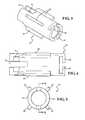
- FIG. 3is a perspective view of a valve body of the pressure regulators of FIGS. 1 through 2B .
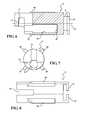
- FIG. 4is a bottom view of the valve body of FIG. 3 .
- FIG. 5is a front view of the valve body of FIG. 3 .
- FIG. 6is a sectional view taken along line 6 - 6 of FIG. 5 .
- FIG. 7is a rear view of the valve body of FIG. 3 .
- FIG. 8is a top view of the valve body of FIG. 3 .
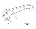
- FIG. 9is a perspective view of a lever of the pressure regulators of FIGS. 1 through 2B .
- the pressure regulator 10is configured to produce a desired output pressure of a fluid from an input pressure of the fluid.
- the pressure regulator 10is configured to reduce the input pressure so that the output pressure is substantially less than the input pressure.
- the pressure regulator 10is a dual-stage pressure regulator having a first stage 12 , which is conventional in the art and will not be described in detail. Dual stage pressure regulators are sometimes employed for regulating the pressure of natural gas or propane in domestic fluid systems, although other uses are possible.
- the first stage 12reduces the pressure of fluid from a storage tank, such as a propane storage tank (not shown), to about 10 psi.
- about 10 psiis the input pressure for a second stage 14 of the pressure regulator 10 .
- the second stage 14is configured to reduce the input pressure from the first stage 12 .
- the second stage 14reduces the approximately 10 psi input pressure to about 11 inches water column output pressure.
- Some regulationsrequire the output pressure not to exceed 2 psi. It should be appreciated that the specific pressure set points of the pressure regulator 10 are not intended to limit the present invention.
- the pressure regulator 10includes a housing formed of an upper housing portion 16 and a lower housing portion 18 that are connected together with fasteners (not shown).
- the housing portions 16 , 18may be formed of metal.
- the pressure regulator 10also includes a ring-shaped diaphragm, generally indicated at 20 , having an outer periphery or lip 22 that is captured between the housing portions 16 , 18 .
- the lower housing portion 18has an annular and U-shaped recess 24 sized and shaped to receive a bottom section of the outer lip 22 .
- the upper housing portion 16has an annular protrusion 26 configured to contact an upper surface of the outer lip 22 .
- the protrusion 26is formed as an arcuate and annular bump on a bottom surface of the upper housing portion 16 .
- the protrusion 26is generally “V” shaped in cross-section.
- the diaphragm 20further includes an annular inner section 28 and a flexible connecting section 30 radially connecting the outer lip 22 and the annular inner section 28 .
- the flexible connecting section 30is generally annular.
- the outer lip 22has a first thickness and the flexible connecting section 30 has a second thickness less than the first thickness, making the flexible connecting section 30 flexible to allow raising and lowering of the annular inner section 28 within the housing.
- the annular inner section 28has at least one, preferably a plurality of locating features formed in an upper surface thereof.
- the locating features shown in FIGS. 1 and 2include alternating annular ridges 32 and grooves 34 . In the embodiment illustrated, two ridges 32 and two grooves 34 are shown.
- the diaphragm 20is made of a flexible material.
- the diaphragm 20is integral, unitary, and one-piece.
- the pressure regulator 10includes a ring-shaped diaphragm plate 36 engaging the diaphragm 20 .
- the diaphragm plate 36is preferably formed as a separate rigid piece configured to be seated on the diaphragm 20 without being rigidly connected to the diaphragm 20 . In some embodiments, however, the diaphragm plate 36 may be rigidly connected to the diaphragm 20 .
- the diaphragm plate 36is formed with at least one, preferably a plurality of locating features (in some cases stamped in the plate 36 when the plate 36 is metal or molded into the plate 36 when the plate 36 is plastic).
- the locating features of the diaphragm plate 36are shaped to co-locate with the locating features of the diaphragm 20 to radially lock the diaphragm plate 36 to the diaphragm 20 .
- the locating features of the diaphragm plate 36include alternating ridges 38 and grooves 40 shaped to mate with the grooves 34 and ridges 32 of the annular inner section 28 , respectively, of the diaphragm 20 . It should be appreciated that, when aligned to one another, the diaphragm plate 36 substantially covers an upper surface of the annular inner section 28 of the diaphragm 20 . It should also be appreciated that the locating features prevent shifting of the diaphragm plate 36 laterally or radially relative to the diaphragm 20 .
- the pressure regulator 10also includes a relief valve, generally indicated at 41 .
- the diaphragm 20 and diaphragm plate 36define a central bore 42 to receive the relief valve 41 .
- the relief valve 41includes a yoke 43 and a shaft or stem 44 extending axially from the yoke 43 .
- the central bore 43receives the stem 44 of the yoke 43 .
- the relief valve 41also includes a head 45 having an outer periphery sized to extend beyond the diameter of the central bore 43 and contact a bottom surface of the annular inner section 28 . This contact seals against fluid flow between the head 44 and the annular inner section 28 under certain conditions.
- the pressure regulator 10includes a spring retainer 46 disposed about the stem 44 .
- the stem 44is slidably received in the spring retainer 46 .
- the pressure regulator 10also includes a regulator spring 47 and a relief spring 49 disposed about the stem 44 and contacting the spring retainer 46 , which supports the regulator spring 47 and the relief spring 49 .
- the pressure regulator 10further includes a relief spring retainer 49 a disposed about the stem 44 and contacting the other end of the relief spring 49 . It should be appreciated that, as pressure increases in a lower pressure chamber 53 , separation may occur between the head 45 and the annular inner section 28 to relieve pressure in the lower pressure chamber 53 , which is conventional in the art.
- the pressure regulator 10also includes a valve body, generally indicated at 52 , located in a passageway 54 defined in the lower housing portion 18 that leads from an inlet 50 to a lower pressure chamber 53 defined in the housing.
- the valve body 52is slidable in the passageway 54 among a plurality of operational positions.
- the pressure regulator 10further includes a disc-shaped valve 56 carried by the valve body 52 .
- the valve 56is fixed to the valve body 52 to move with the valve body 52 .
- the pressure regulator 10also includes a valve seat 58 shaped for engagement by the valve 56 when the valve 56 is in a closed position thereby preventing the flow of fluid from the inlet 50 to the passageway 54 . When the valve 56 and valve body 52 are spaced from the valve seat 58 , fluid is allowed to flow from the inlet 50 through the passageway 54 and into the lower pressure chamber 46 .
- the valve body 52is formed of metal, but may be formed of other materials.
- the valve body 52includes a plurality of radially-extending spacers 60 that centrally align the valve body 52 in the passageway 54 .
- the spacers 60are spaced circumferentially and also provide pathways in the passageway 54 between the valve body 52 and the lower housing portion 18 through which the fluid can move from the inlet 50 to the lower pressure chamber 46 .
- the valve body 52also includes a pair of retainer tangs 62 that hold the valve 56 in position.
- the valve body 52further includes an elongated spring pocket 64 defined therein having an inner surface 65 .
- the pressure regulator 10also includes a lever, generally indicated at 70 , pivotally supported about pivot axis P in the lower housing portion 18 .
- the lever 70has a projection 71 at one end and the other end of the lever 70 is captured in the yoke 43 so that as the yoke 43 rises, the end of the lever 70 also rises.
- the pressure regulator 10includes a driving pin 72 fixed to the lever 70 at a second end of the lever 70 .
- the driving pin 72is sized to fit within a recess 74 defined in the valve body 52 .
- the valve body 52includes a surface 73 that defines the recess 74 and an elongated slot 76 .
- the lever 70has a thickness sized to fit within the slot 76 in the valve body 52 for movement in the slot 76 .
- the driving pin 72contacts the surface 73 defining the recess 74 to urge the valve body 52 toward the valve seat 58 .
- the surface 71presses against the driving pin 72 to pivot the lever 70 clockwise.
- the pressure regulator 10also includes a vibration dampener assisting in preventing vibration and/or humming of the valve body 52 in the passageway 54 .
- the vibration dampeneris a spring 80 located in the spring pocket 64 .
- the spring 80may be a compression spring.
- the spring 80has one end that abuts the inner surface 65 of the valve body 52 and an opposing end engaged by the projection 71 on the lever 70 .
- the spring pocket 64is located offset from a central axis A ( FIG. 6 ) of the valve body 52 . In the embodiment illustrated, the entire spring pocket 64 is spaced radially from the axis A such that the axis A does not pass through any of the spring pocket 64 .
- the valve body 52is pivoted about the driving pin 72 by the spring 80 to provide an off-axis force against the valve body 52 .
- the forceis applied transverse to the axis A.
- One component of this forceis applied perpendicularly to the axis A. This perpendicular component of the force presses the spacers 60 of the valve body 52 against an outer surface of the passageway 54 to reduce vibration or humming of the valve body 52 in the passageway 54 .
- FIGS. 2A through 2CAlternative embodiments 110 , 210 , 310 of the pressure regulator 10 are shown in FIGS. 2A through 2C .
- numeralsare increased by 100 to refer to the same or similar parts described above for the pressure regulator 10 .
- the diaphragm 20 in FIG. 1is referenced as diaphragm 120 in FIG. 2A .
- numeralsare increased by 200 to refer to the same or similar parts described above for the pressure regulator 10 .
- the diaphragm 20 in FIG. 1is the diaphragm 220 in FIG. 2B .
- numeralsare increased by 300 to refer to the same or similar parts described above for the pressure regulator 10 .
- the diaphragm 20 in FIG. 1is the diaphragm 320 in FIG. 2C . It should be appreciated that any features shown in the embodiments of FIGS. 2A, 2B, 2C can be combined with the other features described above with reference to FIG. 1 .
- the pressure regulator 210includes a support 282 (also referred to as a boss) is integrally formed with the lower housing portion 218 . As shown, the support 282 contacts a bottom surface of the yoke 243 when the pressure regulator 210 is at rest, i.e., before any fluid enters through the inlet 250 .
- the regulator spring 247is set to control the output pressure by a threaded spring adjuster 248 (basically threads and unthreads to set spring compression). At rest, the regulator spring 247 pushes the yoke 243 against the support 282 .
- the outer periphery of the head 245by virtue of contact with the annular inner section 228 of the diaphragm 220 , and the yoke 243 by contacting the support 282 prevents the annular inner section 228 from contacting the support 282 or any other portion of the housing.
- the diaphragm 220At rest, as shown in FIG. 2B , the diaphragm 220 only contacts the housing at the outer lip 222 .
- the annular inner section 228 and the flexible connecting section 230are suspended in the housing without any direct contact with the housing. It should be appreciated that this prevents premature abrasion or wear of the diaphragm 220 associated with rubbing against the housing and readies the diaphragm 220 for use.
- the pressure regulator 210includes a plunger 284 having a first end positioned inside the spring 280 located in spring pocket 264 .
- the spring 280has one end that abuts the inner surface 265 of the valve body 252 .
- the plunger 284has a head 286 and an opposing end of the spring 280 is engaged by the head 286 of the plunger 265 . It should also be appreciated that the head 286 is engaged by the projection 271 on the lever 270 .
- the lower housing portion 318defines a plurality of arcuate recesses that act as support surfaces 388 integrally formed with the lower housing portion 318 .
- the support surfaces 388contact a bottom surface of the head 345 of the relief valve 341 when the pressure regulator 310 is at rest, i.e., before any fluid enters through the inlet.
- the regulator spring 347is set to control the output pressure by the threaded spring adjuster 348 (basically threads and unthreads to set spring compression). At rest, the regulator spring 347 pushes the head 345 against the support surfaces 388 .
- the outer periphery of the head 345by virtue of contact with the annular inner section 328 , and by contacting the support surfaces 388 prevents the annular inner section 328 from contacting the any other portion of the housing.
- the diaphragm 320at rest, the diaphragm 320 only contacts the housing at the outer lip 322 .
- the annular inner section 328 and the flexible connecting section 330are suspended in the housing without any direct contact with the housing. It should be appreciated that this prevents premature abrasion or wear of the diaphragm 320 associated with rubbing against the housing and readies the diaphragm 320 for use.
Landscapes
- Physics & Mathematics (AREA)
- Engineering & Computer Science (AREA)
- Fluid Mechanics (AREA)
- General Physics & Mathematics (AREA)
- Automation & Control Theory (AREA)
- Control Of Fluid Pressure (AREA)
- General Engineering & Computer Science (AREA)
- Mechanical Engineering (AREA)
Abstract
Description
Claims (16)
Priority Applications (2)
| Application Number | Priority Date | Filing Date | Title |
|---|---|---|---|
| US14/207,774US9709998B2 (en) | 2013-03-14 | 2014-03-13 | Pressure regulator |
| CA 2846580CA2846580A1 (en) | 2013-03-14 | 2014-03-14 | Pressure regulator |
Applications Claiming Priority (2)
| Application Number | Priority Date | Filing Date | Title |
|---|---|---|---|
| US201361782081P | 2013-03-14 | 2013-03-14 | |
| US14/207,774US9709998B2 (en) | 2013-03-14 | 2014-03-13 | Pressure regulator |
Publications (2)
| Publication Number | Publication Date |
|---|---|
| US20140261787A1 US20140261787A1 (en) | 2014-09-18 |
| US9709998B2true US9709998B2 (en) | 2017-07-18 |
Family
ID=51522016
Family Applications (1)
| Application Number | Title | Priority Date | Filing Date |
|---|---|---|---|
| US14/207,774Active2034-06-04US9709998B2 (en) | 2013-03-14 | 2014-03-13 | Pressure regulator |
Country Status (2)
| Country | Link |
|---|---|
| US (1) | US9709998B2 (en) |
| CA (1) | CA2846580A1 (en) |
Cited By (5)
| Publication number | Priority date | Publication date | Assignee | Title |
|---|---|---|---|---|
| US20170068260A1 (en)* | 2015-09-06 | 2017-03-09 | Fisher Regulators (Shanghai) Co., Ltd. | Lever assembly with a damper for a fluid regulator |
| US20170184204A1 (en)* | 2014-02-20 | 2017-06-29 | Fujikin Incorporated | Valve element and high-temperature-oriented valve |
| US20200038696A1 (en)* | 2017-04-18 | 2020-02-06 | Shigematsu Works Co., Ltd. | Positive pressure exhale valve for a breathing apparatus |
| US20240288887A1 (en)* | 2021-01-11 | 2024-08-29 | Truma Geraetetechnik Gmbh & Co. Kg | A gas-pressure regulator |
| US20240302851A1 (en)* | 2021-03-17 | 2024-09-12 | Neoperl Gmbh | Pressure limiter |
Families Citing this family (3)
| Publication number | Priority date | Publication date | Assignee | Title |
|---|---|---|---|---|
| WO2016207818A1 (en)* | 2015-06-23 | 2016-12-29 | Lorax Systems Inc. | Pressure regulator with shutoff mechanism |
| CN106499864B (en)* | 2015-09-06 | 2021-02-09 | 费希尔调压器(上海)有限公司 | Stationary bar pin assembly for stabilizing air flow and pressure regulation of fluid regulators |
| DE202017104079U1 (en)* | 2017-07-07 | 2017-08-21 | Samson Ag | Actuator for process valves |
Citations (128)
| Publication number | Priority date | Publication date | Assignee | Title |
|---|---|---|---|---|
| US1540439A (en) | 1924-05-12 | 1925-06-02 | Reliance Mfg Company | Gas regulator |
| US1546047A (en) | 1924-05-12 | 1925-07-14 | Reliance Mfg Company | Gas regulator |
| US2052246A (en) | 1935-06-10 | 1936-08-25 | Gen Controls Company | Plunger valve |
| US2442156A (en) | 1944-06-15 | 1948-05-25 | Southern Steel Co | Valve unit for liquefied petroleum gas systems |
| US2694410A (en) | 1950-10-20 | 1954-11-16 | Ey Victor | Fluid pressure regulator |
| US3032054A (en) | 1959-04-13 | 1962-05-01 | Fisher Governor Co | Pressure regulator construction |
| US3042064A (en) | 1957-04-02 | 1962-07-03 | Rockwell Mfg Co | Gas pressure regulator |
| US3160169A (en) | 1961-07-17 | 1964-12-08 | Universal Controls Corp | Check valve unit for a diaphragm type pressure regulator |
| US3339581A (en)* | 1965-06-15 | 1967-09-05 | Textron Inc | Fluid pressure regulator valve |
| US3411522A (en)* | 1966-12-27 | 1968-11-19 | Robert L. Golden | Vacuum regualtor means and parts therefor |
| US3768503A (en) | 1972-10-24 | 1973-10-30 | Golconda Corp | Regulator atmospheric pressure protector |
| US3890999A (en) | 1972-12-15 | 1975-06-24 | Eugene D Moskow | Fluid pressure regulator |
| US3991785A (en) | 1975-04-28 | 1976-11-16 | Sherwood-Selpac Corporation | Flow regulator valve |
| US4152848A (en) | 1978-03-30 | 1979-05-08 | Sherwood-Selpac Corporation | Life support training device |
| US4226257A (en) | 1978-03-30 | 1980-10-07 | Sherwood-Selpac Corporation | Scuba regulator |
| USD258075S (en) | 1978-03-31 | 1981-01-27 | Marshall Brass Company | Gas pressure regulator |
| US4269215A (en) | 1978-10-25 | 1981-05-26 | Rego Company | Vapor flow control valve |
| US4295489A (en) | 1979-10-03 | 1981-10-20 | Fisher Controls Company, Inc. | Pilot-operated back pressure regulator |
| US4356820A (en) | 1980-08-18 | 1982-11-02 | Sherwood-Selpac Corporation | Heat reclaimer for demand regulator |
| US4491149A (en) | 1983-08-05 | 1985-01-01 | Sherwood Selpac Corp. | Pressure regulator with over-pressure safety shut-off feature |
| US4619436A (en) | 1985-08-14 | 1986-10-28 | Fisher Controls International, Inc. | Control regulator having a fabric reinforced diaphragm |
| US4624442A (en) | 1985-01-23 | 1986-11-25 | Duffy John W | Control regulator having a rolling diaphragm |
| US4669761A (en) | 1984-07-19 | 1987-06-02 | Marshall Brass Company | Tubing fitting |
| US4754778A (en) | 1987-05-26 | 1988-07-05 | Fisher Controls International, Inc. | Velocity boost body with wrap-around pitot tube |
| US4782850A (en) | 1987-05-26 | 1988-11-08 | Fisher Controls International, Inc. | Travel stop for diaphragm regulator valve |
| US4842013A (en) | 1988-02-29 | 1989-06-27 | Fisher Controls International, Inc. | Droop compensated direct acting pressure regulator |
| US4889158A (en) | 1988-08-26 | 1989-12-26 | Fisher Controls International, Inc. | Pressure/flow compensated direct acting pressure regulator |
| EP0398858A2 (en) | 1989-05-15 | 1990-11-22 | Fisher Controls International, Inc. | Boost modified, droop compensated direct acting pressure regulator |
| US4972871A (en) | 1988-02-29 | 1990-11-27 | Fisher Controls International, Inc. | Boost modified, droop compensated direct acting pressure regulator |
| US4972868A (en) | 1990-02-08 | 1990-11-27 | Fisher Controls International, Inc. | Flow restrictor and diverter for direct acting pressure regulator |
| US5062449A (en) | 1990-12-28 | 1991-11-05 | Fisher Controls International, Inc. | Vibration dampener for direct acting pressure regulator |
| US5271601A (en) | 1992-07-29 | 1993-12-21 | Fisher Controls International, Inc. | Regulator valve with diaphragm support |
| US5388865A (en) | 1993-12-06 | 1995-02-14 | Fisher Controls International, Inc. | Pressure regulator vent piping coupler |
| US5402820A (en) | 1993-08-06 | 1995-04-04 | Fisher Controls International, Inc. | Stabilizer for pressure regulator |
| USD362298S (en) | 1994-08-22 | 1995-09-12 | S. H. Leggitt Company | Gas regulator |
| USD362297S (en) | 1994-08-22 | 1995-09-12 | S. H. Leggitt Company | Gas regulator |
| USD362488S (en) | 1994-08-22 | 1995-09-19 | S. H. Leggitt Company | Gas regulator |
| USD362712S (en) | 1994-08-22 | 1995-09-26 | S. H. Leggitt Company | Gas regulator |
| USD363761S (en) | 1994-06-02 | 1995-10-31 | Fisher Controls International, Inc. | Valve actuator |
| WO1996030817A1 (en) | 1995-03-31 | 1996-10-03 | Fisher Controls International, Inc. | Gas pressure regulator |
| US5582201A (en) | 1994-11-09 | 1996-12-10 | S. H. Leggitt Company | Gas safety shutoff apparatus |
| WO1997007445A2 (en) | 1995-08-18 | 1997-02-27 | Fisher Controls International, Inc. | Regulator flow fluctuation stabilizer |
| WO1997017641A1 (en) | 1995-11-09 | 1997-05-15 | Fisher Controls International, Inc. | Fluid regulator over-pressure protection device |
| USD379845S (en) | 1994-08-22 | 1997-06-10 | S. H. Leggitt Company | Gas regulator |
| US5662100A (en) | 1996-01-11 | 1997-09-02 | Harsco Corporation | Eductive pressure regulator |
| WO1997037162A1 (en) | 1996-03-29 | 1997-10-09 | S.H. Leggitt Company | Direct-acting boost-enhanced pressure regulator |
| US5697398A (en) | 1995-08-08 | 1997-12-16 | Fisher Controls International, Inc. | Fluid pressure regulator with boost tube unit including stem guide and lever retainer |
| US5709369A (en) | 1996-07-05 | 1998-01-20 | Fisher Controls International, Inc. | Self-aligning valve disc assembly |
| WO1998008150A1 (en) | 1996-08-21 | 1998-02-26 | Fisher Controls International, Inc. | Elastomeric element valve |
| US5739434A (en) | 1996-10-23 | 1998-04-14 | Fisher Controls International, Inc. | Formed metal diaphragm with improved cycle life |
| US5769122A (en) | 1997-02-04 | 1998-06-23 | Fisher Controls International, Inc. | Fluid pressure reduction device |
| US5816286A (en) | 1997-05-30 | 1998-10-06 | Fisher Controls International, Inc. | Pressure unloading pilot operated regulator having pressure limiting check valve |
| USD403050S (en) | 1996-06-27 | 1998-12-22 | Bernard Schlick | Gas regulator |
| US5881765A (en) | 1997-03-28 | 1999-03-16 | S. H. Leggitt Company | Direct-acting boost-enhanced pressure regulator |
| WO1999015823A1 (en) | 1997-09-22 | 1999-04-01 | Fisher Controls International, Inc. | Diagnostic device and method for pressure regulator |
| WO1999015942A1 (en) | 1997-09-22 | 1999-04-01 | Fisher Controls International, Inc. | Intelligent pressure regulator |
| WO1999039122A1 (en) | 1998-01-28 | 1999-08-05 | Fisher Controls International, Inc. | Fluid pressure reduction device with linear flow characteristic |
| US5970977A (en) | 1997-10-15 | 1999-10-26 | Harsco Technologies Corporation | Demand regulator having adjustable air flow |
| US6095196A (en) | 1999-05-18 | 2000-08-01 | Fisher Controls International, Inc. | Tortuous path fluid pressure reduction device |
| WO2000057091A1 (en) | 1999-03-23 | 2000-09-28 | Fisher Controls International, Inc. | Fluid pressure reduction device |
| WO2001001215A1 (en) | 1999-06-29 | 2001-01-04 | Fisher Controls International, Inc. | Regulator flow measurement apparatus |
| WO2001016523A1 (en) | 1999-08-27 | 2001-03-08 | Fisher Controls International, Inc. | Adaptive predictive control of pressure in a natural gas distribution system |
| US6213150B1 (en) | 2000-04-18 | 2001-04-10 | Fisher Controls International, Inc. | Fluid pressure reduction disks with taper nut retention device |
| US6223769B1 (en) | 1998-09-28 | 2001-05-01 | S. H. Leggitt Company | Gas pressure sensor and indicator apparatus for recreational vehicles and the like |
| WO2002005049A1 (en) | 2000-07-07 | 2002-01-17 | S.H. Leggitt Company | Direct-acting pressure regulator |
| WO2002010625A1 (en) | 2000-07-31 | 2002-02-07 | S.H. Leggitt Company | Bonnet securement for gas pressure regulators |
| US6371156B1 (en) | 2000-08-10 | 2002-04-16 | Fisher Controls International, Inc. | No-bleed pilot for pressure regulating valve |
| US6382253B1 (en) | 2001-02-13 | 2002-05-07 | Fisher Controls International, Inc. | Fluid pressure reduction device with integral guides |
| WO2002057861A1 (en) | 2001-01-16 | 2002-07-25 | Fisher Controls International Llc | Self-centering magnet assembly for use in a linear travel measurement device |
| WO2002063403A2 (en) | 2001-02-02 | 2002-08-15 | Fisher Controls International Llc | Reporting regulator for managing a gas transportation system |
| WO2002071165A2 (en) | 2001-02-28 | 2002-09-12 | Fisher Controls International Llc | Low power regulator system and method |
| USD464582S1 (en) | 2001-10-10 | 2002-10-22 | Fisher Controls International, Inc. | Regulator flow measurement module housing |
| WO2002088861A1 (en) | 2001-04-27 | 2002-11-07 | Fisher Controls International, Llc | Intelligent regulator with input/output capabilities |
| WO2003073189A1 (en) | 2002-02-27 | 2003-09-04 | S.H. Leggitt Company | Fluid pressure regulator with stabilizer |
| US20040040600A1 (en) | 2002-09-03 | 2004-03-04 | Cavagna Group Societa Per Azioni | Device for regulating the flow of gas toward user equipment |
| US6701957B2 (en) | 2001-08-16 | 2004-03-09 | Fisher Controls International Llc | Fluid pressure reduction device |
| WO2004053612A1 (en) | 2002-12-09 | 2004-06-24 | S.H. Leggitt Company | Automatic changeover regulator |
| WO2004077187A1 (en) | 2003-02-24 | 2004-09-10 | Fisher Controls International Llc | Regulator flow measurement apparatus |
| WO2004088444A2 (en) | 2003-03-27 | 2004-10-14 | Fisher Controls International Llc | Pressure reducing fluid regulators |
| US20040261855A1 (en) | 2003-06-27 | 2004-12-30 | Hart Justin Wade | Pressure regulator with integrated reverse pressure exhaust |
| EP1562095A2 (en) | 2004-02-04 | 2005-08-10 | S.H.Leggitt Company | Pressure regulator with improved outlet pressure control |
| WO2005073821A1 (en) | 2004-01-21 | 2005-08-11 | Fisher Controls International Llc | Pressure loaded pilot valve system and method for a regulator without atmospheric bleed |
| US6953182B2 (en) | 2002-09-13 | 2005-10-11 | Fisher Controls International Llc. | Retainer lock nut for fluid pressure control device |
| US6957661B1 (en) | 2003-03-19 | 2005-10-25 | Harsco Technologies Corporation | Valve with pressurization rate reduction device |
| WO2005103542A1 (en) | 2004-03-26 | 2005-11-03 | Fisher Controls International Llc | Fluid pressure reduction devices |
| US6971403B2 (en) | 2000-07-07 | 2005-12-06 | S. H. Leggitt Company | Direct-acting pressure regulator |
| US20060096643A1 (en) | 2004-11-10 | 2006-05-11 | Mccarty Michael W | Seal assembly for a fluid pressure control device |
| EP1441273B1 (en) | 2003-01-22 | 2006-06-28 | Cavagna Group S.p.A. | Pressure regulator with pressure gauge, particularly for LPG tanks |
| US20060185736A1 (en) | 2005-02-23 | 2006-08-24 | Cavagna Group S.P.A. | Two-stage pressure regulator for pressurized gas |
| EP1698815A1 (en) | 2005-03-04 | 2006-09-06 | Mesura | Operating device of a safety valve of a gas regulator |
| US20070075287A1 (en) | 2005-10-05 | 2007-04-05 | Harsco Technologies Corporation | Regulator union swivel connection |
| WO2007106374A2 (en) | 2006-03-10 | 2007-09-20 | Fisher Controls International, Llc | Pressure reducing regulator with adjustable feature |
| WO2007126863A1 (en) | 2006-04-18 | 2007-11-08 | Fisher Controls International Llc | Fluid pressure reduction devices |
| EP1857905A1 (en) | 2006-05-16 | 2007-11-21 | Mesura | Gas expansion regulator and flow meter and check valve for gas vent |
| US20070272313A1 (en) | 2006-05-23 | 2007-11-29 | Olds Charles M | Pressure regulator with improved outlet pressure control |
| WO2008016430A1 (en) | 2006-07-31 | 2008-02-07 | Fisher Controls International Llc | Fluid pressure reduction device for high pressure-drop ratios |
| WO2008018953A2 (en) | 2006-08-04 | 2008-02-14 | Fisher Controls International Llc | Flow restricting seat ring for pressure regulators |
| EP0994291B1 (en) | 1998-10-12 | 2008-02-20 | Cavagna Group S.p.A. | Two-stage pressure regulator with dual safety system, particularly for liquefied-gas cylinders |
| US20080053535A1 (en) | 2006-08-30 | 2008-03-06 | Leggitt Don C | Cylinder valve regulator |
| US20080078460A1 (en) | 2006-09-29 | 2008-04-03 | Roper Daniel G | Positioning Device for Pressure Regulator |
| US20080258095A1 (en) | 2007-04-20 | 2008-10-23 | Fisher Controls International Llc | Adjustable Disc Mechanism for Gas Regulator |
| US20080258099A1 (en) | 2007-04-20 | 2008-10-23 | Fisher Controls International Llc | Service Regulator Vent |
| US20080257421A1 (en) | 2007-04-20 | 2008-10-23 | Fisher Controls International Llc | Integral Overpressure Monitoring Device |
| US20080258096A1 (en) | 2007-04-20 | 2008-10-23 | Fisher Controls International Llc | Gas Regulator Flow Boost Cartridge |
| US20080257424A1 (en) | 2007-04-20 | 2008-10-23 | Fisher Controls International Llc | Flow Valve Port for a Gas Regulator |
| US20080257423A1 (en) | 2007-04-20 | 2008-10-23 | Fisher Controls International Llc | Secondary Seat for Gas Regulator |
| US20080258097A1 (en) | 2007-04-18 | 2008-10-23 | James Lyman Griffin | Two-piece trim for use with fluid regulators |
| US20080257427A1 (en) | 2007-04-20 | 2008-10-23 | Fisher Controls International Llc | Service Regulator with Improved Boost Performance |
| US20080257418A1 (en) | 2007-04-20 | 2008-10-23 | Fisher Controls International Llc | Pressure Averaging Sense Tube For Gas Regulator |
| US20080258098A1 (en)* | 2007-04-23 | 2008-10-23 | James Chester Hawkins | Modular regulator platform |
| US20090065073A1 (en) | 2007-09-11 | 2009-03-12 | Davis David B | Metal sealing disk having an elastomeric backing for use with fluid regulators |
| US20090260697A1 (en) | 2008-04-21 | 2009-10-22 | Emerson Process Management Regulator Technologies, Inc. | Valve Body with Dual Sense Mechanism |
| US20090261281A1 (en) | 2008-04-18 | 2009-10-22 | Fisher Controls International Llc | Balanced Port Housing with Integrated Flow Conditioning |
| WO2009132006A1 (en) | 2008-04-21 | 2009-10-29 | Emerson Process Management Regulator Technologies, Inc. | Pressure loaded service regulator with pressure balanced trim |
| WO2009142861A2 (en) | 2008-05-20 | 2009-11-26 | Fisher Controls International Llc | Apparatus to regulate fluid flow |
| US20090314360A1 (en) | 2008-06-23 | 2009-12-24 | Fisher Controls International Llc | Fluid Regulator |
| USD607355S1 (en) | 2008-06-23 | 2010-01-05 | Fisher Controls International Llc | Gas regulator |
| US20100025603A1 (en) | 2008-08-01 | 2010-02-04 | Brian Burlage | Apparatus to control a fluid flow characteristic of fluid regulator bypass valves |
| US20100051117A1 (en) | 2008-09-02 | 2010-03-04 | Chun Lin | Fluid flow control members for use with valves |
| USD616067S1 (en) | 2006-07-17 | 2010-05-18 | Cavagna Group S.P.A. | Apparatus for gas delivery |
| WO2010065254A1 (en) | 2008-12-03 | 2010-06-10 | Emerson Process Management Regulator Technologies, Inc. | Valve seat apparatus having positive retention for use with fluid control devices |
| WO2010077472A2 (en) | 2008-12-17 | 2010-07-08 | Emerson Process Management Regulator Technologies, Inc. | Internal relief valve apparatus for use with loading regulators |
| US20100243080A1 (en) | 2005-03-25 | 2010-09-30 | Fisher Controls International Llc | Gas Pressure Regulator and Method for Assembling and Disassembling the Regulator |
| EP1943446B1 (en) | 2005-09-12 | 2010-10-27 | Fisher Controls International Llc | Tank manifold assembly |
| US20100270490A1 (en) | 2009-04-27 | 2010-10-28 | Emerson Process Management Regulator Technologies, Inc. | Anti-gradient cupped seat for pressure regulator |
| US20100269925A1 (en) | 2009-04-27 | 2010-10-28 | Emerson Process Management Regulator Technologies, Inc. | Self-Aligning Spring Seat for Fluid Regulator and Fluid Regulator Comprising Self-Aligning Spring Seat |
| US20100289258A1 (en) | 2009-05-15 | 2010-11-18 | Cavagna Group | Method and apparatus for assembling pressure reducing fuel regulator |
| US20100313971A1 (en) | 2009-04-02 | 2010-12-16 | Moore J Reese | Regulator with high flow rate stability |
- 2014
- 2014-03-13USUS14/207,774patent/US9709998B2/enactiveActive
- 2014-03-14CACA 2846580patent/CA2846580A1/ennot_activeAbandoned
Patent Citations (240)
| Publication number | Priority date | Publication date | Assignee | Title |
|---|---|---|---|---|
| US1540439A (en) | 1924-05-12 | 1925-06-02 | Reliance Mfg Company | Gas regulator |
| US1546047A (en) | 1924-05-12 | 1925-07-14 | Reliance Mfg Company | Gas regulator |
| US2052246A (en) | 1935-06-10 | 1936-08-25 | Gen Controls Company | Plunger valve |
| US2442156A (en) | 1944-06-15 | 1948-05-25 | Southern Steel Co | Valve unit for liquefied petroleum gas systems |
| US2694410A (en) | 1950-10-20 | 1954-11-16 | Ey Victor | Fluid pressure regulator |
| US3042064A (en) | 1957-04-02 | 1962-07-03 | Rockwell Mfg Co | Gas pressure regulator |
| US3032054A (en) | 1959-04-13 | 1962-05-01 | Fisher Governor Co | Pressure regulator construction |
| US3160169A (en) | 1961-07-17 | 1964-12-08 | Universal Controls Corp | Check valve unit for a diaphragm type pressure regulator |
| US3339581A (en)* | 1965-06-15 | 1967-09-05 | Textron Inc | Fluid pressure regulator valve |
| US3411522A (en)* | 1966-12-27 | 1968-11-19 | Robert L. Golden | Vacuum regualtor means and parts therefor |
| US3768503A (en) | 1972-10-24 | 1973-10-30 | Golconda Corp | Regulator atmospheric pressure protector |
| US3890999A (en) | 1972-12-15 | 1975-06-24 | Eugene D Moskow | Fluid pressure regulator |
| US3991785A (en) | 1975-04-28 | 1976-11-16 | Sherwood-Selpac Corporation | Flow regulator valve |
| US4152848A (en) | 1978-03-30 | 1979-05-08 | Sherwood-Selpac Corporation | Life support training device |
| US4226257A (en) | 1978-03-30 | 1980-10-07 | Sherwood-Selpac Corporation | Scuba regulator |
| USD258075S (en) | 1978-03-31 | 1981-01-27 | Marshall Brass Company | Gas pressure regulator |
| US4269215A (en) | 1978-10-25 | 1981-05-26 | Rego Company | Vapor flow control valve |
| US4295489A (en) | 1979-10-03 | 1981-10-20 | Fisher Controls Company, Inc. | Pilot-operated back pressure regulator |
| US4356820A (en) | 1980-08-18 | 1982-11-02 | Sherwood-Selpac Corporation | Heat reclaimer for demand regulator |
| US4491149A (en) | 1983-08-05 | 1985-01-01 | Sherwood Selpac Corp. | Pressure regulator with over-pressure safety shut-off feature |
| US4669761A (en) | 1984-07-19 | 1987-06-02 | Marshall Brass Company | Tubing fitting |
| EP0192625B1 (en) | 1985-01-23 | 1989-05-31 | Fisher Controls International, Inc. | Control regulator having a rolling diaphragm |
| US4624442A (en) | 1985-01-23 | 1986-11-25 | Duffy John W | Control regulator having a rolling diaphragm |
| US4619436A (en) | 1985-08-14 | 1986-10-28 | Fisher Controls International, Inc. | Control regulator having a fabric reinforced diaphragm |
| EP0229005B1 (en) | 1985-08-14 | 1989-04-26 | Fisher Controls International, Inc. | Control regulator having a fabric reinforced diaphragm |
| US4754778A (en) | 1987-05-26 | 1988-07-05 | Fisher Controls International, Inc. | Velocity boost body with wrap-around pitot tube |
| US4782850A (en) | 1987-05-26 | 1988-11-08 | Fisher Controls International, Inc. | Travel stop for diaphragm regulator valve |
| EP0331665B1 (en) | 1988-02-29 | 1994-04-20 | Fisher Controls International, Inc. | Droop compensated direct acting pressure regulator |
| US4842013A (en) | 1988-02-29 | 1989-06-27 | Fisher Controls International, Inc. | Droop compensated direct acting pressure regulator |
| US4972871A (en) | 1988-02-29 | 1990-11-27 | Fisher Controls International, Inc. | Boost modified, droop compensated direct acting pressure regulator |
| DE68914708T2 (en) | 1988-02-29 | 1994-11-03 | Fisher Controls Int | Droop compensated direct acting pressure regulator. |
| US4889158A (en) | 1988-08-26 | 1989-12-26 | Fisher Controls International, Inc. | Pressure/flow compensated direct acting pressure regulator |
| EP0398858A2 (en) | 1989-05-15 | 1990-11-22 | Fisher Controls International, Inc. | Boost modified, droop compensated direct acting pressure regulator |
| US4972868A (en) | 1990-02-08 | 1990-11-27 | Fisher Controls International, Inc. | Flow restrictor and diverter for direct acting pressure regulator |
| US5062449A (en) | 1990-12-28 | 1991-11-05 | Fisher Controls International, Inc. | Vibration dampener for direct acting pressure regulator |
| US5271601A (en) | 1992-07-29 | 1993-12-21 | Fisher Controls International, Inc. | Regulator valve with diaphragm support |
| EP0581287B1 (en) | 1992-07-29 | 1997-06-11 | Fisher Controls International, Inc. | Regulator valve with diaphragm support |
| US5402820A (en) | 1993-08-06 | 1995-04-04 | Fisher Controls International, Inc. | Stabilizer for pressure regulator |
| US5388865A (en) | 1993-12-06 | 1995-02-14 | Fisher Controls International, Inc. | Pressure regulator vent piping coupler |
| USD363761S (en) | 1994-06-02 | 1995-10-31 | Fisher Controls International, Inc. | Valve actuator |
| USD379845S (en) | 1994-08-22 | 1997-06-10 | S. H. Leggitt Company | Gas regulator |
| USD362712S (en) | 1994-08-22 | 1995-09-26 | S. H. Leggitt Company | Gas regulator |
| USD362488S (en) | 1994-08-22 | 1995-09-19 | S. H. Leggitt Company | Gas regulator |
| USD362297S (en) | 1994-08-22 | 1995-09-12 | S. H. Leggitt Company | Gas regulator |
| USD362298S (en) | 1994-08-22 | 1995-09-12 | S. H. Leggitt Company | Gas regulator |
| US5582201A (en) | 1994-11-09 | 1996-12-10 | S. H. Leggitt Company | Gas safety shutoff apparatus |
| EP0949553B1 (en) | 1995-03-31 | 2001-05-16 | Fisher Controls International, Inc. | Gas pressure regulator |
| DE69612879T2 (en) | 1995-03-31 | 2002-03-28 | Fisher Controls International Inc., Clayton | Gas pressure regulator |
| WO1996030817A1 (en) | 1995-03-31 | 1996-10-03 | Fisher Controls International, Inc. | Gas pressure regulator |
| DE69606525T2 (en) | 1995-03-31 | 2000-07-27 | Fisher Controls International Inc., Clayton | GAS PRESSURE REGULATOR |
| EP0817990B1 (en) | 1995-03-31 | 2000-02-02 | Fisher Controls International, Inc. | Gas pressure regulator |
| US5996617A (en) | 1995-03-31 | 1999-12-07 | Fisher Controls Internationals Inc. | Low pressure regulator |
| US5740833A (en) | 1995-03-31 | 1998-04-21 | Fisher Controls International, Inc. | Gas pressure regulator |
| US5697398A (en) | 1995-08-08 | 1997-12-16 | Fisher Controls International, Inc. | Fluid pressure regulator with boost tube unit including stem guide and lever retainer |
| US5735306A (en) | 1995-08-18 | 1998-04-07 | Fisher Controls International, Inc. | Regulator flow fluctuation stabilizer |
| WO1997007445A2 (en) | 1995-08-18 | 1997-02-27 | Fisher Controls International, Inc. | Regulator flow fluctuation stabilizer |
| EP0880733B1 (en) | 1995-08-18 | 2002-03-13 | Fisher Controls International, Inc. | Regulator flow fluctuation stabilizer |
| WO1997017641A1 (en) | 1995-11-09 | 1997-05-15 | Fisher Controls International, Inc. | Fluid regulator over-pressure protection device |
| US5662100A (en) | 1996-01-11 | 1997-09-02 | Harsco Corporation | Eductive pressure regulator |
| WO1997037162A1 (en) | 1996-03-29 | 1997-10-09 | S.H. Leggitt Company | Direct-acting boost-enhanced pressure regulator |
| USD403050S (en) | 1996-06-27 | 1998-12-22 | Bernard Schlick | Gas regulator |
| US5709369A (en) | 1996-07-05 | 1998-01-20 | Fisher Controls International, Inc. | Self-aligning valve disc assembly |
| US5964446A (en) | 1996-08-21 | 1999-10-12 | Fisher Controls International, Inc. | Elastomeric element valve |
| WO1998008150A1 (en) | 1996-08-21 | 1998-02-26 | Fisher Controls International, Inc. | Elastomeric element valve |
| US6102071A (en) | 1996-08-21 | 2000-08-15 | Fisher Controls International, Inc. | Elastomeric element valve |
| EP1020779B1 (en) | 1996-08-21 | 2007-10-17 | Fisher Controls International LLC | Elastomeric element valve |
| EP0920657B1 (en) | 1996-08-21 | 2002-11-13 | Fisher Controls International, Inc. | Elastomeric element valve |
| US5739434A (en) | 1996-10-23 | 1998-04-14 | Fisher Controls International, Inc. | Formed metal diaphragm with improved cycle life |
| EP0934559B1 (en) | 1996-10-23 | 2002-01-02 | Fisher Controls International, Inc. | Formed metal diaphragm with improved cycle life |
| WO1998018069A1 (en) | 1996-10-23 | 1998-04-30 | Fisher Controls International, Inc. | Formed metal diaphragm with improved cycle life |
| US5941281A (en) | 1997-02-04 | 1999-08-24 | Fisher Controls International, Inc. | Fluid pressure reduction device |
| EP1566585B1 (en) | 1997-02-04 | 2009-06-03 | Fisher Controls International Llc | Fluid pressure reduction device |
| DE69830565T2 (en) | 1997-02-04 | 2006-05-11 | Fisher Controls International Llc | PRESSURE REDUCING DEVICE |
| WO1998034057A1 (en) | 1997-02-04 | 1998-08-06 | Fisher Controls International, Inc. | Fluid pressure reduction device |
| EP0958466B1 (en) | 1997-02-04 | 2005-06-15 | Fisher Controls International LLC | Fluid pressure reduction device |
| US5769122A (en) | 1997-02-04 | 1998-06-23 | Fisher Controls International, Inc. | Fluid pressure reduction device |
| US5881765A (en) | 1997-03-28 | 1999-03-16 | S. H. Leggitt Company | Direct-acting boost-enhanced pressure regulator |
| US5816286A (en) | 1997-05-30 | 1998-10-06 | Fisher Controls International, Inc. | Pressure unloading pilot operated regulator having pressure limiting check valve |
| WO1999015823A1 (en) | 1997-09-22 | 1999-04-01 | Fisher Controls International, Inc. | Diagnostic device and method for pressure regulator |
| DE69820653T2 (en) | 1997-09-22 | 2004-09-30 | Fisher Controls International, Inc. | INTELLIGENT PRESSURE REGULATOR |
| DE69832400T2 (en) | 1997-09-22 | 2006-07-13 | Fischer Controls International Llc | DIAGNOSTIC DEVICE AND METHOD FOR PRESSURE REGULATOR |
| US6178997B1 (en) | 1997-09-22 | 2001-01-30 | Fisher Controls International, Inc. | Intelligent pressure regulator |
| US6056008A (en) | 1997-09-22 | 2000-05-02 | Fisher Controls International, Inc. | Intelligent pressure regulator |
| US6035878A (en) | 1997-09-22 | 2000-03-14 | Fisher Controls International, Inc. | Diagnostic device and method for pressure regulator |
| EP1015950B1 (en) | 1997-09-22 | 2003-12-17 | Fisher Controls International, Inc. | Intelligent pressure regulator |
| WO1999015942A1 (en) | 1997-09-22 | 1999-04-01 | Fisher Controls International, Inc. | Intelligent pressure regulator |
| EP1017950B1 (en) | 1997-09-22 | 2005-11-16 | Fisher Controls International LLC | Diagnostic device and method for pressure regulator |
| US5970977A (en) | 1997-10-15 | 1999-10-26 | Harsco Technologies Corporation | Demand regulator having adjustable air flow |
| WO1999039122A1 (en) | 1998-01-28 | 1999-08-05 | Fisher Controls International, Inc. | Fluid pressure reduction device with linear flow characteristic |
| DE69918949T2 (en) | 1998-01-28 | 2005-07-28 | Fisher Controls International Llc | FLUID PRESSURE REDUCTION DEVICE WITH LINEAR FLOW CHARACTERISTICS |
| EP1049893B1 (en) | 1998-01-28 | 2004-07-28 | Fisher Controls International LLC | Fluid pressure reduction device with linear flow characteristic |
| US6026859A (en) | 1998-01-28 | 2000-02-22 | Fisher Controls International, Inc. | Fluid pressure reduction device with linear flow characteristic |
| US6223769B1 (en) | 1998-09-28 | 2001-05-01 | S. H. Leggitt Company | Gas pressure sensor and indicator apparatus for recreational vehicles and the like |
| EP0994291B1 (en) | 1998-10-12 | 2008-02-20 | Cavagna Group S.p.A. | Two-stage pressure regulator with dual safety system, particularly for liquefied-gas cylinders |
| US6244297B1 (en) | 1999-03-23 | 2001-06-12 | Fisher Controls International, Inc. | Fluid pressure reduction device |
| EP1165992B1 (en) | 1999-03-23 | 2006-06-14 | Fisher Controls International LLC | Fluid pressure reduction device |
| WO2000057091A1 (en) | 1999-03-23 | 2000-09-28 | Fisher Controls International, Inc. | Fluid pressure reduction device |
| DE60028742T2 (en) | 1999-03-23 | 2007-05-24 | Fisher Controls International Llc | fluid pressure reduction |
| WO2000070253A1 (en) | 1999-05-18 | 2000-11-23 | Fisher Controls International, Inc. | Fluid pressure reduction device with tortuous paths |
| US6095196A (en) | 1999-05-18 | 2000-08-01 | Fisher Controls International, Inc. | Tortuous path fluid pressure reduction device |
| WO2001001214A1 (en) | 1999-06-29 | 2001-01-04 | Fisher Controls International, Inc. | Regulator diagnostics system and method |
| DE60029326T2 (en) | 1999-06-29 | 2007-07-05 | Fisher Controls International Llc | CONTROL DIAGNOSTIC DEVICE AND METHOD |
| WO2001001215A1 (en) | 1999-06-29 | 2001-01-04 | Fisher Controls International, Inc. | Regulator flow measurement apparatus |
| US6539315B1 (en) | 1999-06-29 | 2003-03-25 | Fisher Controls International, Inc. | Regulator flow measurement apparatus |
| US6536469B2 (en) | 1999-06-29 | 2003-03-25 | Fisher Controls International, Inc. | Self-centering magnet assembly for use in a linear travel measurement device |
| EP1198740B1 (en) | 1999-06-29 | 2003-10-08 | Fisher Controls International, Inc. | Regulator flow measurement apparatus |
| US6441744B1 (en) | 1999-06-29 | 2002-08-27 | Fisher Controls International, Inc. | Regulator diagnostics system and method |
| US6903659B2 (en) | 1999-06-29 | 2005-06-07 | Fisher Controls International Llc. | Low power regulator system and method |
| US6895351B2 (en) | 1999-06-29 | 2005-05-17 | Fisher Controls International Llc | Regulator flow measurement apparatus |
| EP1196834B1 (en) | 1999-06-29 | 2006-07-12 | Fisher Controls International LLC | Regulator diagnostics system and method |
| DE60005840T2 (en) | 1999-06-29 | 2004-07-22 | Fisher Controls International, Inc. | FLOW MEASURING DEVICE IN A REGULATOR |
| WO2001016523A1 (en) | 1999-08-27 | 2001-03-08 | Fisher Controls International, Inc. | Adaptive predictive control of pressure in a natural gas distribution system |
| US6416268B2 (en) | 2000-04-18 | 2002-07-09 | Fisher Controls International, Inc. | Mechanical fastening apparatus |
| US6213150B1 (en) | 2000-04-18 | 2001-04-10 | Fisher Controls International, Inc. | Fluid pressure reduction disks with taper nut retention device |
| US7064671B2 (en) | 2000-06-23 | 2006-06-20 | Fisher Controls International Llc | Low power regulator system and method |
| US6971403B2 (en) | 2000-07-07 | 2005-12-06 | S. H. Leggitt Company | Direct-acting pressure regulator |
| WO2002005049A1 (en) | 2000-07-07 | 2002-01-17 | S.H. Leggitt Company | Direct-acting pressure regulator |
| US6668855B2 (en) | 2000-07-07 | 2003-12-30 | S. H. Leggitt Company | Direct-acting pressure regulator |
| US6672331B2 (en) | 2000-07-31 | 2004-01-06 | S. H. Leggitt Company | Bonnet securement for gas pressure regulators |
| WO2002010625A1 (en) | 2000-07-31 | 2002-02-07 | S.H. Leggitt Company | Bonnet securement for gas pressure regulators |
| US6371156B1 (en) | 2000-08-10 | 2002-04-16 | Fisher Controls International, Inc. | No-bleed pilot for pressure regulating valve |
| WO2002057861A1 (en) | 2001-01-16 | 2002-07-25 | Fisher Controls International Llc | Self-centering magnet assembly for use in a linear travel measurement device |
| DE60110836T2 (en) | 2001-01-16 | 2006-03-16 | Fisher Controls International Llc | SELF-CENTERING MAGNETIC ARRANGEMENT FOR USE IN A LINEAR ALIGNMENT KNIFE |
| EP1354252B1 (en) | 2001-01-16 | 2005-05-11 | Fisher Controls International Llc | Self-centering magnet assembly for use in a linear travel measurement device |
| WO2002063403A2 (en) | 2001-02-02 | 2002-08-15 | Fisher Controls International Llc | Reporting regulator for managing a gas transportation system |
| US7049975B2 (en) | 2001-02-02 | 2006-05-23 | Fisher Controls International Llc | Reporting regulator for managing a gas transportation system |
| EP1428088B1 (en) | 2001-02-02 | 2011-04-27 | Fisher Controls International Llc | Reporting regulator for managing a gas transportation system |
| US6382253B1 (en) | 2001-02-13 | 2002-05-07 | Fisher Controls International, Inc. | Fluid pressure reduction device with integral guides |
| EP1362201B1 (en) | 2001-02-13 | 2008-10-08 | Fisher Controls International Llc | Valve with fluid pressure reduction device with integral guides |
| WO2002066875A1 (en) | 2001-02-13 | 2002-08-29 | Fisher Controls International Llc | Valve with fluid pressure reduction device with integral guides |
| DE60221105T2 (en) | 2001-02-28 | 2008-03-13 | Fisher Controls International Llc | LOW ENERGY CONTROL SYSTEM AND METHOD |
| EP1519253A3 (en) | 2001-02-28 | 2007-01-17 | Fisher Controls International LLC | Low power regulator system and method |
| EP1519253A2 (en) | 2001-02-28 | 2005-03-30 | Fisher Controls International LLC | Low power regulator system and method |
| EP1366392B1 (en) | 2001-02-28 | 2007-07-11 | Fisher Controls International LLC | Low power regulator system and method |
| WO2002071165A2 (en) | 2001-02-28 | 2002-09-12 | Fisher Controls International Llc | Low power regulator system and method |
| US6830061B2 (en) | 2001-04-27 | 2004-12-14 | Fisher Controls International Llc | Intelligent regulator with input/output capabilities |
| WO2002088861A1 (en) | 2001-04-27 | 2002-11-07 | Fisher Controls International, Llc | Intelligent regulator with input/output capabilities |
| US7013918B2 (en) | 2001-08-16 | 2006-03-21 | Fisher Controls International Llc. | Fluid pressure reduction device |
| US6701957B2 (en) | 2001-08-16 | 2004-03-09 | Fisher Controls International Llc | Fluid pressure reduction device |
| US6935370B2 (en) | 2001-08-16 | 2005-08-30 | Fisher Controls International Llc | Fluid pressure reduction device |
| USD464582S1 (en) | 2001-10-10 | 2002-10-22 | Fisher Controls International, Inc. | Regulator flow measurement module housing |
| US20040007270A1 (en) | 2002-02-27 | 2004-01-15 | Olds Charles M. | Fluid pressure regulator with stabilizer |
| WO2003073189A1 (en) | 2002-02-27 | 2003-09-04 | S.H. Leggitt Company | Fluid pressure regulator with stabilizer |
| US6948519B2 (en) | 2002-09-03 | 2005-09-27 | Cavagna Group Societa' Per Azioni | Device for regulating the flow of gas toward user equipment |
| US20040040600A1 (en) | 2002-09-03 | 2004-03-04 | Cavagna Group Societa Per Azioni | Device for regulating the flow of gas toward user equipment |
| EP1396774B1 (en) | 2002-09-03 | 2006-07-12 | Cavagna Group Societa' per Azioni | Gas flow regulator with a flow limiter |
| US6953182B2 (en) | 2002-09-13 | 2005-10-11 | Fisher Controls International Llc. | Retainer lock nut for fluid pressure control device |
| US7328718B2 (en) | 2002-12-09 | 2008-02-12 | S.H. Leggitt Company | Automatic changeover regulator |
| WO2004053612A1 (en) | 2002-12-09 | 2004-06-24 | S.H. Leggitt Company | Automatic changeover regulator |
| EP1441273B1 (en) | 2003-01-22 | 2006-06-28 | Cavagna Group S.p.A. | Pressure regulator with pressure gauge, particularly for LPG tanks |
| WO2004077187A1 (en) | 2003-02-24 | 2004-09-10 | Fisher Controls International Llc | Regulator flow measurement apparatus |
| US6957661B1 (en) | 2003-03-19 | 2005-10-25 | Harsco Technologies Corporation | Valve with pressurization rate reduction device |
| EP2278427A1 (en) | 2003-03-27 | 2011-01-26 | Fisher Controls International, Inc. | Pressure reducing fluid regulators |
| EP2278426A1 (en) | 2003-03-27 | 2011-01-26 | Fisher Controls International, Inc. | Pressure reducing fluid regulators |
| WO2004088444A2 (en) | 2003-03-27 | 2004-10-14 | Fisher Controls International Llc | Pressure reducing fluid regulators |
| US6968857B2 (en) | 2003-03-27 | 2005-11-29 | Emerson Process Control | Pressure reducing fluid regulators |
| US20040261855A1 (en) | 2003-06-27 | 2004-12-30 | Hart Justin Wade | Pressure regulator with integrated reverse pressure exhaust |
| WO2005003876A1 (en) | 2003-06-27 | 2005-01-13 | Fisher Controls International, L.L.C. | Pressure regulator with ingrated reverse pressure exhaust |
| US7318447B2 (en) | 2004-01-21 | 2008-01-15 | Fisher Controls International Llc. | Pressure loaded pilot system and method for a regulator without atmospheric bleed |
| WO2005073821A1 (en) | 2004-01-21 | 2005-08-11 | Fisher Controls International Llc | Pressure loaded pilot valve system and method for a regulator without atmospheric bleed |
| EP1709501B1 (en) | 2004-01-21 | 2009-01-28 | Fisher Controls International Llc | Pressure loaded pilot valve system and method for a regulator without atmospheric bleed |
| EP1562095A2 (en) | 2004-02-04 | 2005-08-10 | S.H.Leggitt Company | Pressure regulator with improved outlet pressure control |
| US7261119B2 (en) | 2004-02-04 | 2007-08-28 | S.H. Leggitt Company | Pressure regulator with improved outlet pressure control |
| US7320340B2 (en) | 2004-03-26 | 2008-01-22 | Fisher Controls International Llc | Fluid pressure reduction devices |
| WO2005103542A1 (en) | 2004-03-26 | 2005-11-03 | Fisher Controls International Llc | Fluid pressure reduction devices |
| EP1735557B1 (en) | 2004-03-26 | 2009-09-30 | Fisher Controls International LLC | Fluid pressure reduction devices |
| US7578314B2 (en) | 2004-11-10 | 2009-08-25 | Fisher Controls International Llc | Seal assembly for a fluid pressure control device |
| US20060096643A1 (en) | 2004-11-10 | 2006-05-11 | Mccarty Michael W | Seal assembly for a fluid pressure control device |
| EP1809551B1 (en) | 2004-11-10 | 2011-02-16 | Fisher Controls International Llc | Seal assembly for a fluid pressure control device |
| US20090309059A1 (en) | 2004-11-10 | 2009-12-17 | Fisher Controls International Llc | Seal Assembly for a Fluid Pressure Control Device |
| US20060185736A1 (en) | 2005-02-23 | 2006-08-24 | Cavagna Group S.P.A. | Two-stage pressure regulator for pressurized gas |
| EP1698815A1 (en) | 2005-03-04 | 2006-09-06 | Mesura | Operating device of a safety valve of a gas regulator |
| US20100243080A1 (en) | 2005-03-25 | 2010-09-30 | Fisher Controls International Llc | Gas Pressure Regulator and Method for Assembling and Disassembling the Regulator |
| US20100243081A1 (en) | 2005-03-25 | 2010-09-30 | Fisher Controls International Llc | Gas Pressure Regulator and Method for Assembling and Disassembling the Regulator |
| EP1943446B1 (en) | 2005-09-12 | 2010-10-27 | Fisher Controls International Llc | Tank manifold assembly |
| US20070075287A1 (en) | 2005-10-05 | 2007-04-05 | Harsco Technologies Corporation | Regulator union swivel connection |
| EP1999530B1 (en) | 2006-03-10 | 2010-05-19 | Fisher Controls International LLC | Pressure reducing regulator with adjustable feature |
| WO2007106374A2 (en) | 2006-03-10 | 2007-09-20 | Fisher Controls International, Llc | Pressure reducing regulator with adjustable feature |
| US7828009B2 (en) | 2006-03-10 | 2010-11-09 | Tescom Corporation | Pressure reducing regulator with adjustable feature |
| WO2007126863A1 (en) | 2006-04-18 | 2007-11-08 | Fisher Controls International Llc | Fluid pressure reduction devices |
| US7802592B2 (en) | 2006-04-18 | 2010-09-28 | Fisher Controls International, Llc | Fluid pressure reduction devices |
| US20100319799A1 (en) | 2006-04-18 | 2010-12-23 | Mccarty Michael Wildie | Fluid pressure reduction devices |
| EP1857905A1 (en) | 2006-05-16 | 2007-11-21 | Mesura | Gas expansion regulator and flow meter and check valve for gas vent |
| WO2007132128A1 (en) | 2006-05-16 | 2007-11-22 | Mesura | Gas flow channel check valve and expansion gas flow meter and control device |
| US20070272313A1 (en) | 2006-05-23 | 2007-11-29 | Olds Charles M | Pressure regulator with improved outlet pressure control |
| USD623274S1 (en) | 2006-07-17 | 2010-09-07 | Cavagna Group S.P.A. | Apparatus for gas delivery |
| USD623272S1 (en) | 2006-07-17 | 2010-09-07 | Cavagna Group S.P.A. | Apparatus for gas delivery |
| USD623273S1 (en) | 2006-07-17 | 2010-09-07 | Cavagna Group S.P.A. | Apparatus for gas delivery |
| USD616067S1 (en) | 2006-07-17 | 2010-05-18 | Cavagna Group S.P.A. | Apparatus for gas delivery |
| US7766045B2 (en) | 2006-07-31 | 2010-08-03 | Fisher Controls International Llc | Fluid pressure reduction device for high pressure-drop ratios |
| WO2008016430A1 (en) | 2006-07-31 | 2008-02-07 | Fisher Controls International Llc | Fluid pressure reduction device for high pressure-drop ratios |
| US7896028B2 (en) | 2006-08-04 | 2011-03-01 | Fisher Controls International Llc | Flow restricted seat ring for pressure regulators |
| WO2008018953A2 (en) | 2006-08-04 | 2008-02-14 | Fisher Controls International Llc | Flow restricting seat ring for pressure regulators |
| US20080053535A1 (en) | 2006-08-30 | 2008-03-06 | Leggitt Don C | Cylinder valve regulator |
| WO2008042665A1 (en) | 2006-09-29 | 2008-04-10 | Fisher Controls International Llc | Positioning device for pressure regulator |
| US20080078460A1 (en) | 2006-09-29 | 2008-04-03 | Roper Daniel G | Positioning Device for Pressure Regulator |
| US20080258097A1 (en) | 2007-04-18 | 2008-10-23 | James Lyman Griffin | Two-piece trim for use with fluid regulators |
| WO2008130849A1 (en) | 2007-04-18 | 2008-10-30 | Fisher Controls International Llc | Two-piece trim for use with fluid regulators |
| US20080258096A1 (en) | 2007-04-20 | 2008-10-23 | Fisher Controls International Llc | Gas Regulator Flow Boost Cartridge |
| US20080257427A1 (en) | 2007-04-20 | 2008-10-23 | Fisher Controls International Llc | Service Regulator with Improved Boost Performance |
| WO2008131255A1 (en) | 2007-04-20 | 2008-10-30 | Fisher Controls International Llc | Service regulator with improved boost performance |
| WO2008131235A1 (en) | 2007-04-20 | 2008-10-30 | Fisher Controls International Llc | Adjustable disc mechanism for gas regulator |
| WO2008131254A1 (en) | 2007-04-20 | 2008-10-30 | Fisher Controls International Llc | Service regulator vent |
| WO2008131248A1 (en) | 2007-04-20 | 2008-10-30 | Fisher Controls International Llc | Improved flow valve port for a gas regulator |
| WO2008131246A1 (en) | 2007-04-20 | 2008-10-30 | Fisher Controls International Llc | Secondary seat for gas regulator |
| WO2008131110A2 (en) | 2007-04-20 | 2008-10-30 | Fisher Controls International Llc | Integral overpressure monitoring device |
| WO2008131250A1 (en) | 2007-04-20 | 2008-10-30 | Fisher Controls International Llc | Pressure averaging sense tube for gas regulator |
| US20080258095A1 (en) | 2007-04-20 | 2008-10-23 | Fisher Controls International Llc | Adjustable Disc Mechanism for Gas Regulator |
| US20080258099A1 (en) | 2007-04-20 | 2008-10-23 | Fisher Controls International Llc | Service Regulator Vent |
| US20080257418A1 (en) | 2007-04-20 | 2008-10-23 | Fisher Controls International Llc | Pressure Averaging Sense Tube For Gas Regulator |
| US20080257421A1 (en) | 2007-04-20 | 2008-10-23 | Fisher Controls International Llc | Integral Overpressure Monitoring Device |
| US20080257424A1 (en) | 2007-04-20 | 2008-10-23 | Fisher Controls International Llc | Flow Valve Port for a Gas Regulator |
| US20080257423A1 (en) | 2007-04-20 | 2008-10-23 | Fisher Controls International Llc | Secondary Seat for Gas Regulator |
| WO2008131237A1 (en) | 2007-04-20 | 2008-10-30 | Fisher Controls International Llc | Gas regulator flow boost cartridge |
| WO2008134246A2 (en) | 2007-04-23 | 2008-11-06 | Fisher Controls International Llc | Modular regulator platform |
| US20080258098A1 (en)* | 2007-04-23 | 2008-10-23 | James Chester Hawkins | Modular regulator platform |
| WO2009035864A2 (en) | 2007-09-11 | 2009-03-19 | Fisher Controls International Llc | Metal sealing disk having an elastomeric backing for use with fluid regulators |
| US20090065073A1 (en) | 2007-09-11 | 2009-03-12 | Davis David B | Metal sealing disk having an elastomeric backing for use with fluid regulators |
| WO2010047848A2 (en) | 2008-04-18 | 2010-04-29 | Fisher Controls International Llc | Balanced port housing with integrated flow conditioning |
| US20090261281A1 (en) | 2008-04-18 | 2009-10-22 | Fisher Controls International Llc | Balanced Port Housing with Integrated Flow Conditioning |
| US20100071786A1 (en) | 2008-04-21 | 2010-03-25 | Emerson Process Management Regulator Technologies, Inc. | Pressure Loaded Service Regulator with Pressure Balanced Trim |
| WO2009132006A1 (en) | 2008-04-21 | 2009-10-29 | Emerson Process Management Regulator Technologies, Inc. | Pressure loaded service regulator with pressure balanced trim |
| WO2009132007A2 (en) | 2008-04-21 | 2009-10-29 | Emerson Process Management Regulator Technologies, Inc. | Valve body with dual sense mechanism |
| US20090260697A1 (en) | 2008-04-21 | 2009-10-22 | Emerson Process Management Regulator Technologies, Inc. | Valve Body with Dual Sense Mechanism |
| US20090288718A1 (en) | 2008-05-20 | 2009-11-26 | Jason Jablonski | Apparatus to regulate fluid flow |
| WO2009142861A2 (en) | 2008-05-20 | 2009-11-26 | Fisher Controls International Llc | Apparatus to regulate fluid flow |
| WO2010008676A2 (en) | 2008-06-23 | 2010-01-21 | Fisher Controls International Llc | Fluid regulator |
| US20090314360A1 (en) | 2008-06-23 | 2009-12-24 | Fisher Controls International Llc | Fluid Regulator |
| USD607355S1 (en) | 2008-06-23 | 2010-01-05 | Fisher Controls International Llc | Gas regulator |
| US20100025603A1 (en) | 2008-08-01 | 2010-02-04 | Brian Burlage | Apparatus to control a fluid flow characteristic of fluid regulator bypass valves |
| WO2010014291A1 (en) | 2008-08-01 | 2010-02-04 | Fisher Controls International Llc | Apparatus to control a fluid flow characteristic of fluid regulator bypass valves |
| US20100051117A1 (en) | 2008-09-02 | 2010-03-04 | Chun Lin | Fluid flow control members for use with valves |
| WO2010065254A1 (en) | 2008-12-03 | 2010-06-10 | Emerson Process Management Regulator Technologies, Inc. | Valve seat apparatus having positive retention for use with fluid control devices |
| WO2010077472A2 (en) | 2008-12-17 | 2010-07-08 | Emerson Process Management Regulator Technologies, Inc. | Internal relief valve apparatus for use with loading regulators |
| US20100313971A1 (en) | 2009-04-02 | 2010-12-16 | Moore J Reese | Regulator with high flow rate stability |
| US20100270490A1 (en) | 2009-04-27 | 2010-10-28 | Emerson Process Management Regulator Technologies, Inc. | Anti-gradient cupped seat for pressure regulator |
| WO2010126809A1 (en) | 2009-04-27 | 2010-11-04 | Emerson Process Management Regulator Technologies, Inc. | Pressure regulator |
| WO2010126762A1 (en) | 2009-04-27 | 2010-11-04 | Emerson Process Management Regulator Technologies, Inc. | Self-aligning spring seat for fluid regulator and fluid regulator comprising self-aligning spring seat |
| US20100269925A1 (en) | 2009-04-27 | 2010-10-28 | Emerson Process Management Regulator Technologies, Inc. | Self-Aligning Spring Seat for Fluid Regulator and Fluid Regulator Comprising Self-Aligning Spring Seat |
| US20100289258A1 (en) | 2009-05-15 | 2010-11-18 | Cavagna Group | Method and apparatus for assembling pressure reducing fuel regulator |
Non-Patent Citations (15)
| Title |
|---|
| Cramer Decker Propane Equipment, Regulators First and Second Stage Residential Sherwood Regulators, pp. 4-12, dated prior to Mar. 14, 2013; 9 pages. |
| English language abstract and machine-assisted English translation for EP 1 698 815 extracted from the www.espacenet.com database on Apr. 15, 2014. |
| English language abstract and machine-assisted English translation for EP 1 857 905 extracted from the www.espacenet.com database on Apr. 15, 2014. |
| English language abstract and machine-assisted English translation for WO 2007 132128 extracted from the www.espacenet.com database on Apr. 15, 2014. |
| English language abstract for DE 689 14 708 extracted from the www.espacenet.com database on Apr. 15, 2014. |
| English language abstract for DE 696 06 525 extracted from the www.espacenet.com database on Apr. 15, 2014. |
| English language abstract for DE 696 12 879 extracted from the www.espacenet.com database on Apr. 15, 2014. |
| English language abstract for DE 698 20 653 extracted from the www.espacenet.com database on Apr. 15, 2014. |
| English language abstract for DE 698 30 565 extracted from the www.espacenet.com database on Apr. 15, 2014. |
| English language abstract for DE 698 32 400 extracted from the www.espacenet.com database on Apr. 15, 2014. |
| English language abstract for DE 699 18 949 extracted from the www.espacenet.com database on Apr. 15, 2014. |
| MacMillan Dictionary, "Adjacent", Jul. 2016.* |
| NGVI North America, Regulators N-LPR Vapor Regulator Description & Dimensions, catalog, pp. 8-9, dated prior to Mar. 14, 2013; 2 pages. |
| REGO, LP-Gas & Anhydrous Ammonia Equipment, Section A Regulators and Accessories, catalog, pp. A1-A36, Elon, North Carolina, USA, 37 pages. |
| Sherwood LPG Products, LPG Regulator, Apr. 2007; 16 pages. |
Cited By (8)
| Publication number | Priority date | Publication date | Assignee | Title |
|---|---|---|---|---|
| US20170184204A1 (en)* | 2014-02-20 | 2017-06-29 | Fujikin Incorporated | Valve element and high-temperature-oriented valve |
| US10731763B2 (en)* | 2014-02-20 | 2020-08-04 | Fujikin Incorporated | Valve element and high-temperature-oriented valve |
| US20170068260A1 (en)* | 2015-09-06 | 2017-03-09 | Fisher Regulators (Shanghai) Co., Ltd. | Lever assembly with a damper for a fluid regulator |
| US10222811B2 (en)* | 2015-09-06 | 2019-03-05 | Fisher Regulators (Shanghai) Co., Ltd. | Lever assembly with a damper for a fluid regulator |
| US20200038696A1 (en)* | 2017-04-18 | 2020-02-06 | Shigematsu Works Co., Ltd. | Positive pressure exhale valve for a breathing apparatus |
| US12036428B2 (en)* | 2017-04-18 | 2024-07-16 | Shigematsu Works Co., Ltd. | Positive pressure exhale valve for a breathing apparatus |
| US20240288887A1 (en)* | 2021-01-11 | 2024-08-29 | Truma Geraetetechnik Gmbh & Co. Kg | A gas-pressure regulator |
| US20240302851A1 (en)* | 2021-03-17 | 2024-09-12 | Neoperl Gmbh | Pressure limiter |
Also Published As
| Publication number | Publication date |
|---|---|
| US20140261787A1 (en) | 2014-09-18 |
| CA2846580A1 (en) | 2014-09-14 |
Similar Documents
| Publication | Publication Date | Title |
|---|---|---|
| US9709998B2 (en) | Pressure regulator | |
| RU2529777C2 (en) | Valve seat with forced position fixation for use with control units for fluid medium flow rate | |
| EP2188555B1 (en) | Metal sealing disk having an elastomeric backing for use with fluid regulators | |
| JP2009301109A (en) | Pressure reducing valve | |
| WO1996001445A1 (en) | A fluid pressure regulator | |
| US9081390B2 (en) | Back pressure valve | |
| US11988288B2 (en) | Poppet-style valve arrangements | |
| JP2016196957A (en) | Valve device | |
| US9453587B2 (en) | Flow rate adjusting device | |
| EP3362718A1 (en) | Control member for a fluid control device | |
| US9639093B2 (en) | Self-aligning axially constrained regulator valve assembly | |
| KR101584479B1 (en) | Fluid controller actuator | |
| JP5551038B2 (en) | Valve device | |
| EP3418847B1 (en) | Flow regulation valve | |
| EP1811356B1 (en) | Pressure-reducing valve | |
| JP2005351309A (en) | Valve body and valve with the valve body | |
| JP2005273555A (en) | Regulator for high-pressure fluid | |
| US11060622B2 (en) | Cartridge having a pressurized control disk for a water fitting | |
| KR101792371B1 (en) | Control valve | |
| KR101443010B1 (en) | Pipe assembly for control valve | |
| JP5022971B2 (en) | Pressure regulator | |
| JP4458419B2 (en) | Pressure reducing valve cassette and pressure reducing valve | |
| JP2007323599A (en) | Pressure reducing valve | |
| JP2023159716A (en) | relief valve | |
| KR101409580B1 (en) | Pipe assembly for control valve |
Legal Events
| Date | Code | Title | Description |
|---|---|---|---|
| AS | Assignment | Owner name:MARSHALL EXCELSIOR CO., MICHIGAN Free format text:ASSIGNMENT OF ASSIGNORS INTEREST;ASSIGNORS:BLANCHARD, FREDERICK W.;ZUCK, JAMES C.;REEL/FRAME:032453/0997 Effective date:20140313 | |
| AS | Assignment | Owner name:MADISON CAPITAL FUNDING LLC, AS AGENT, ILLINOIS Free format text:SECURITY INTEREST;ASSIGNOR:MARSHALL EXCELSIOR CO.;REEL/FRAME:041646/0795 Effective date:20170320 | |
| STCF | Information on status: patent grant | Free format text:PATENTED CASE | |
| FEPP | Fee payment procedure | Free format text:ENTITY STATUS SET TO UNDISCOUNTED (ORIGINAL EVENT CODE: BIG.) | |
| FEPP | Fee payment procedure | Free format text:PETITION RELATED TO MAINTENANCE FEES GRANTED (ORIGINAL EVENT CODE: PTGR) | |
| MAFP | Maintenance fee payment | Free format text:PAYMENT OF MAINTENANCE FEE, 4TH YEAR, LARGE ENTITY (ORIGINAL EVENT CODE: M1551); ENTITY STATUS OF PATENT OWNER: LARGE ENTITY Year of fee payment:4 | |
| AS | Assignment | Owner name:APOGEM CAPITAL LLC, AS SUCCESSOR AGENT, ILLINOIS Free format text:ASSIGNMENT OF INTELLECTUAL PROPERTY SECURITY AGREEMENT;ASSIGNOR:MADISON CAPITAL FUNDING LLC, AS RETIRING AGENT;REEL/FRAME:059796/0319 Effective date:20220401 | |
| MAFP | Maintenance fee payment | Free format text:PAYMENT OF MAINTENANCE FEE, 8TH YEAR, LARGE ENTITY (ORIGINAL EVENT CODE: M1552); ENTITY STATUS OF PATENT OWNER: LARGE ENTITY Year of fee payment:8 |