US9707369B2 - Modular flow cassette - Google Patents
Modular flow cassetteDownload PDFInfo
- Publication number
- US9707369B2 US9707369B2US13/931,566US201313931566AUS9707369B2US 9707369 B2US9707369 B2US 9707369B2US 201313931566 AUS201313931566 AUS 201313931566AUS 9707369 B2US9707369 B2US 9707369B2
- Authority
- US
- United States
- Prior art keywords
- flow
- passage
- flow rate
- processor
- cassette
- Prior art date
- Legal status (The legal status is an assumption and is not a legal conclusion. Google has not performed a legal analysis and makes no representation as to the accuracy of the status listed.)
- Active, expires
Links
- 238000005259measurementMethods0.000claimsabstractdescription28
- 239000012530fluidSubstances0.000claimsabstractdescription21
- 238000000034methodMethods0.000claimsdescription22
- 230000005355Hall effectEffects0.000claimsdescription6
- 238000011144upstream manufacturingMethods0.000claimsdescription3
- 239000007789gasSubstances0.000description76
- 239000000203mixtureSubstances0.000description19
- 230000029058respiratory gaseous exchangeEffects0.000description8
- GWUAFYNDGVNXRS-UHFFFAOYSA-Nhelium;molecular oxygenChemical compound[He].O=OGWUAFYNDGVNXRS-UHFFFAOYSA-N0.000description7
- 239000003570airSubstances0.000description6
- QVGXLLKOCUKJST-UHFFFAOYSA-Natomic oxygenChemical compound[O]QVGXLLKOCUKJST-UHFFFAOYSA-N0.000description5
- 238000005516engineering processMethods0.000description5
- 239000001301oxygenSubstances0.000description5
- 229910052760oxygenInorganic materials0.000description5
- 230000003750conditioning effectEffects0.000description4
- 238000006243chemical reactionMethods0.000description3
- 238000004891communicationMethods0.000description3
- 238000013461designMethods0.000description3
- 239000001307heliumSubstances0.000description3
- 229910052734heliumInorganic materials0.000description3
- SWQJXJOGLNCZEY-UHFFFAOYSA-Nhelium atomChemical compound[He]SWQJXJOGLNCZEY-UHFFFAOYSA-N0.000description3
- OKTJSMMVPCPJKN-UHFFFAOYSA-NCarbonChemical compound[C]OKTJSMMVPCPJKN-UHFFFAOYSA-N0.000description2
- MYMOFIZGZYHOMD-UHFFFAOYSA-NDioxygenChemical compoundO=OMYMOFIZGZYHOMD-UHFFFAOYSA-N0.000description2
- 238000009530blood pressure measurementMethods0.000description2
- 230000006378damageEffects0.000description2
- 238000010586diagramMethods0.000description2
- 210000004072lungAnatomy0.000description2
- 239000000463materialSubstances0.000description2
- XLYOFNOQVPJJNP-UHFFFAOYSA-NwaterSubstancesOXLYOFNOQVPJJNP-UHFFFAOYSA-N0.000description2
- 206010009126Chronic respiratory failureDiseases0.000description1
- 208000027418Wounds and injuryDiseases0.000description1
- 239000012080ambient airSubstances0.000description1
- 238000013459approachMethods0.000description1
- 239000002274desiccantSubstances0.000description1
- 230000009189divingEffects0.000description1
- 238000001914filtrationMethods0.000description1
- 230000006870functionEffects0.000description1
- 208000014674injuryDiseases0.000description1
- 239000007788liquidSubstances0.000description1
- 230000007774longtermEffects0.000description1
- 230000013011matingEffects0.000description1
- 230000005226mechanical processes and functionsEffects0.000description1
- 229940075473medical gasesDrugs0.000description1
- 238000012986modificationMethods0.000description1
- 230000004048modificationEffects0.000description1
- 235000019645odorNutrition0.000description1
- 238000011022operating instructionMethods0.000description1
- 230000002265preventionEffects0.000description1
- 230000000241respiratory effectEffects0.000description1
- 201000004193respiratory failureDiseases0.000description1
- 238000007789sealingMethods0.000description1
- 239000007787solidSubstances0.000description1
- 239000000126substanceSubstances0.000description1
- 238000002627tracheal intubationMethods0.000description1
Images


Classifications
- A—HUMAN NECESSITIES
- A61—MEDICAL OR VETERINARY SCIENCE; HYGIENE
- A61M—DEVICES FOR INTRODUCING MEDIA INTO, OR ONTO, THE BODY; DEVICES FOR TRANSDUCING BODY MEDIA OR FOR TAKING MEDIA FROM THE BODY; DEVICES FOR PRODUCING OR ENDING SLEEP OR STUPOR
- A61M16/00—Devices for influencing the respiratory system of patients by gas treatment, e.g. ventilators; Tracheal tubes
- A61M16/10—Preparation of respiratory gases or vapours
- A61M16/12—Preparation of respiratory gases or vapours by mixing different gases
- A—HUMAN NECESSITIES
- A61—MEDICAL OR VETERINARY SCIENCE; HYGIENE
- A61M—DEVICES FOR INTRODUCING MEDIA INTO, OR ONTO, THE BODY; DEVICES FOR TRANSDUCING BODY MEDIA OR FOR TAKING MEDIA FROM THE BODY; DEVICES FOR PRODUCING OR ENDING SLEEP OR STUPOR
- A61M16/00—Devices for influencing the respiratory system of patients by gas treatment, e.g. ventilators; Tracheal tubes
- A61M16/021—Devices for influencing the respiratory system of patients by gas treatment, e.g. ventilators; Tracheal tubes operated by electrical means
- A61M16/022—Control means therefor
- A61M16/024—Control means therefor including calculation means, e.g. using a processor
- G—PHYSICS
- G01—MEASURING; TESTING
- G01F—MEASURING VOLUME, VOLUME FLOW, MASS FLOW OR LIQUID LEVEL; METERING BY VOLUME
- G01F1/00—Measuring the volume flow or mass flow of fluid or fluent solid material wherein the fluid passes through a meter in a continuous flow
- G01F1/05—Measuring the volume flow or mass flow of fluid or fluent solid material wherein the fluid passes through a meter in a continuous flow by using mechanical effects
- G01F1/34—Measuring the volume flow or mass flow of fluid or fluent solid material wherein the fluid passes through a meter in a continuous flow by using mechanical effects by measuring pressure or differential pressure
- G01F1/50—Correcting or compensating means
- A—HUMAN NECESSITIES
- A61—MEDICAL OR VETERINARY SCIENCE; HYGIENE
- A61M—DEVICES FOR INTRODUCING MEDIA INTO, OR ONTO, THE BODY; DEVICES FOR TRANSDUCING BODY MEDIA OR FOR TAKING MEDIA FROM THE BODY; DEVICES FOR PRODUCING OR ENDING SLEEP OR STUPOR
- A61M16/00—Devices for influencing the respiratory system of patients by gas treatment, e.g. ventilators; Tracheal tubes
- A61M16/10—Preparation of respiratory gases or vapours
- A61M16/105—Filters
- A61M16/106—Filters in a path
- A—HUMAN NECESSITIES
- A61—MEDICAL OR VETERINARY SCIENCE; HYGIENE
- A61M—DEVICES FOR INTRODUCING MEDIA INTO, OR ONTO, THE BODY; DEVICES FOR TRANSDUCING BODY MEDIA OR FOR TAKING MEDIA FROM THE BODY; DEVICES FOR PRODUCING OR ENDING SLEEP OR STUPOR
- A61M16/00—Devices for influencing the respiratory system of patients by gas treatment, e.g. ventilators; Tracheal tubes
- A61M16/20—Valves specially adapted to medical respiratory devices
- A61M16/208—Non-controlled one-way valves, e.g. exhalation, check, pop-off non-rebreathing valves
- A—HUMAN NECESSITIES
- A61—MEDICAL OR VETERINARY SCIENCE; HYGIENE
- A61M—DEVICES FOR INTRODUCING MEDIA INTO, OR ONTO, THE BODY; DEVICES FOR TRANSDUCING BODY MEDIA OR FOR TAKING MEDIA FROM THE BODY; DEVICES FOR PRODUCING OR ENDING SLEEP OR STUPOR
- A61M16/00—Devices for influencing the respiratory system of patients by gas treatment, e.g. ventilators; Tracheal tubes
- A61M16/0003—Accessories therefor, e.g. sensors, vibrators, negative pressure
- A61M2016/0027—Accessories therefor, e.g. sensors, vibrators, negative pressure pressure meter
- A—HUMAN NECESSITIES
- A61—MEDICAL OR VETERINARY SCIENCE; HYGIENE
- A61M—DEVICES FOR INTRODUCING MEDIA INTO, OR ONTO, THE BODY; DEVICES FOR TRANSDUCING BODY MEDIA OR FOR TAKING MEDIA FROM THE BODY; DEVICES FOR PRODUCING OR ENDING SLEEP OR STUPOR
- A61M16/00—Devices for influencing the respiratory system of patients by gas treatment, e.g. ventilators; Tracheal tubes
- A61M16/0003—Accessories therefor, e.g. sensors, vibrators, negative pressure
- A61M2016/003—Accessories therefor, e.g. sensors, vibrators, negative pressure with a flowmeter
- A61M2016/0033—Accessories therefor, e.g. sensors, vibrators, negative pressure with a flowmeter electrical
- A61M2016/0039—Accessories therefor, e.g. sensors, vibrators, negative pressure with a flowmeter electrical in the inspiratory circuit
- A—HUMAN NECESSITIES
- A61—MEDICAL OR VETERINARY SCIENCE; HYGIENE
- A61M—DEVICES FOR INTRODUCING MEDIA INTO, OR ONTO, THE BODY; DEVICES FOR TRANSDUCING BODY MEDIA OR FOR TAKING MEDIA FROM THE BODY; DEVICES FOR PRODUCING OR ENDING SLEEP OR STUPOR
- A61M2205/00—General characteristics of the apparatus
- A61M2205/12—General characteristics of the apparatus with interchangeable cassettes forming partially or totally the fluid circuit
- A—HUMAN NECESSITIES
- A61—MEDICAL OR VETERINARY SCIENCE; HYGIENE
- A61M—DEVICES FOR INTRODUCING MEDIA INTO, OR ONTO, THE BODY; DEVICES FOR TRANSDUCING BODY MEDIA OR FOR TAKING MEDIA FROM THE BODY; DEVICES FOR PRODUCING OR ENDING SLEEP OR STUPOR
- A61M2205/00—General characteristics of the apparatus
- A61M2205/33—Controlling, regulating or measuring
- A61M2205/3317—Electromagnetic, inductive or dielectric measuring means
- A—HUMAN NECESSITIES
- A61—MEDICAL OR VETERINARY SCIENCE; HYGIENE
- A61M—DEVICES FOR INTRODUCING MEDIA INTO, OR ONTO, THE BODY; DEVICES FOR TRANSDUCING BODY MEDIA OR FOR TAKING MEDIA FROM THE BODY; DEVICES FOR PRODUCING OR ENDING SLEEP OR STUPOR
- A61M2205/00—General characteristics of the apparatus
- A61M2205/33—Controlling, regulating or measuring
- A61M2205/3368—Temperature
- A—HUMAN NECESSITIES
- A61—MEDICAL OR VETERINARY SCIENCE; HYGIENE
- A61M—DEVICES FOR INTRODUCING MEDIA INTO, OR ONTO, THE BODY; DEVICES FOR TRANSDUCING BODY MEDIA OR FOR TAKING MEDIA FROM THE BODY; DEVICES FOR PRODUCING OR ENDING SLEEP OR STUPOR
- A61M2205/00—General characteristics of the apparatus
- A61M2205/50—General characteristics of the apparatus with microprocessors or computers
- A—HUMAN NECESSITIES
- A61—MEDICAL OR VETERINARY SCIENCE; HYGIENE
- A61M—DEVICES FOR INTRODUCING MEDIA INTO, OR ONTO, THE BODY; DEVICES FOR TRANSDUCING BODY MEDIA OR FOR TAKING MEDIA FROM THE BODY; DEVICES FOR PRODUCING OR ENDING SLEEP OR STUPOR
- A61M2205/00—General characteristics of the apparatus
- A61M2205/60—General characteristics of the apparatus with identification means
- A61M2205/6018—General characteristics of the apparatus with identification means providing set-up signals for the apparatus configuration
- A—HUMAN NECESSITIES
- A61—MEDICAL OR VETERINARY SCIENCE; HYGIENE
- A61M—DEVICES FOR INTRODUCING MEDIA INTO, OR ONTO, THE BODY; DEVICES FOR TRANSDUCING BODY MEDIA OR FOR TAKING MEDIA FROM THE BODY; DEVICES FOR PRODUCING OR ENDING SLEEP OR STUPOR
- A61M2205/00—General characteristics of the apparatus
- A61M2205/60—General characteristics of the apparatus with identification means
- A61M2205/6054—Magnetic identification systems
- A—HUMAN NECESSITIES
- A61—MEDICAL OR VETERINARY SCIENCE; HYGIENE
- A61M—DEVICES FOR INTRODUCING MEDIA INTO, OR ONTO, THE BODY; DEVICES FOR TRANSDUCING BODY MEDIA OR FOR TAKING MEDIA FROM THE BODY; DEVICES FOR PRODUCING OR ENDING SLEEP OR STUPOR
- A61M2205/00—General characteristics of the apparatus
- A61M2205/70—General characteristics of the apparatus with testing or calibration facilities
- A61M2205/702—General characteristics of the apparatus with testing or calibration facilities automatically during use
Definitions
- the present disclosuregenerally relates to gas mixing and, in particular, to accurate control of the flow rate of a gas flow from a pressurized source.
- Respiratorstypically provide a flow of air, or other breathing gases, at an elevated pressure during an inhalation interval, followed by an exhalation interval where the pressurized air is diverted so that the air within the patient's lungs can be naturally expelled.
- Conventional respiratorsmay be configured to accept one or more breathing gases, for example “pure oxygen” or “heliox 80/20” (a mixture of 80% helium with 20% oxygen) from external sources.
- the exact gas mixture delivered to the patientmay be a mixture of various breathing gases since the specific percentage required for a particular patient may not be commercially available and must be custom mixed in the respirator.
- a flow cassettein certain embodiments, has a housing with an inlet and an outlet and a passage therebetween.
- the flow cassettealso has a temperature sensor disposed within the passage and configured to measure the temperature of a fluid flowing through the passage, a flow rate sensor disposed within the passage and configured to measure a flow rate of the fluid flowing through the passage, and a processor coupled to the temperature sensor and flow rate sensor.
- the processoris configured to accept measurements of temperature and flow rate from the temperature sensor and flow rate sensor, respectively, and provide a compensated flow rate.
- a method of configuring a ventilator for a patientcomprising the step of installing a flow cassette into a ventilator.
- the flow cassettehas a housing with an inlet and an outlet and a passage therebetween.
- the flow cassettealso has a temperature sensor disposed within the passage and configured to measure the temperature of a fluid flowing through the passage, a flow rate sensor disposed within the passage and configured to measure a flow rate of the fluid flowing through the passage, and a processor coupled to the temperature sensor and flow rate sensor.
- the processoris configured to accept measurements of temperature and flow rate from the temperature sensor and flow rate sensor, respectively, and provide a compensated flow rate.
- a ventilatorin certain embodiments, has an output flow channel configured to mate with a supply limb, an input flow channel configured to accept a gas from a source, and a flow cassette that has a housing with an inlet and an outlet and a passage therebetween.
- the flow cassettealso has a temperature sensor disposed within the passage and configured to measure the temperature of a fluid flowing through the passage, a flow rate sensor disposed within the passage and configured to measure a flow rate of the fluid flowing through the passage, and a processor coupled to the temperature sensor and flow rate sensor.
- the processoris configured to accept measurements of temperature and flow rate from the temperature sensor and flow rate sensor, respectively, and provide a compensated flow rate.
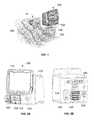
- FIG. 1depicts a patient using an exemplary ventilator according to certain aspects of the present disclosure.
- FIGS. 2A and 2Bare front and rear views of the exemplary ventilator according to certain aspects of the present disclosure.
- FIG. 3is a block diagram of an exemplary flow cassette according to certain aspects of the present disclosure.
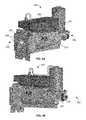
- FIGS. 4A-4Bdepict an exemplary flow cassette according to certain aspects of the present disclosure.
- FIG. 5Ais a cross-section of the flow cassette of FIGS. 4A-4B according to certain aspects of the present disclosure.
- FIG. 5Bis an enlarged view of a portion of FIG. 5A according to certain aspects of the present disclosure.
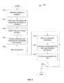
- FIG. 6is a flow chart of an exemplary configuration process according to certain aspects of the present disclosure.
- the disclosed systems and methods of measuring flow rates and compensating for the composition of the gas or gas mixture as well as the temperature of the measured gasprovides increased accuracy compared to flow measurements made within conventional ventilators.
- helioxmeans a mixture of oxygen and helium.
- the mixturemay contain a designated percentage of each gas, for example “heliox 70/30” containing approximately 70% helium and 30% oxygen.
- Helioxmay contain trace amounts of other gases.
- gasshall be interpreted to mean both a single material in gaseous form, for example oxygen, and a mixture of two or more gases, for example air or heliox.
- a gasmay include water or other liquids in the form of vapor or suspended droplets.
- a gasmay also include solid particulates suspended in the gas.
- purewhen used with reference to a gas, means that the gas meets commonly accepted medical standards for purity and content.
- temperature sensormeans a device configured to measure temperature and provide a signal that is related to the measured temperature.
- a temperature sensormay include electronics to provide a drive current or voltage and/or measure a current or voltage.
- the electronicsmay further include conditioning and conversion circuitry and/or a processor to convert the measured value to a signal that may be in analog or digital form.
- pressure sensormeans a device configured to measure a gas pressure and provide a signal that is related to the measured pressure.
- a pressure sensormay include electronics to provide a drive current or voltage and/or measure a current or voltage.
- the electronicsmay further include conditioning and conversion circuitry and/or a processor to convert the measured value to a signal that may be in analog or digital form.
- the pressuremay be provided in absolute terms or “gauge” pressure, i.e. relative to ambient atmospheric pressure.
- Hall Effect sensormeans a device configured to detect the presence of a magnet or other magnetic element without making physical contact (non-contacting).
- a Hall Effect sensormay include electronics to provide a drive current or voltage and/or measure a current or voltage.
- the electronicsmay further include conditioning and conversion circuitry and/or a processor to convert the measured value to a signal that may be in analog or digital form.
- FIG. 1depicts a patient 10 using an exemplary ventilator 100 according to certain aspects of the present disclosure.
- the ventilator 100is connected to the patient 10 through a supply tube or “limb” 104 and a return or exhaust limb 106 .
- the supply and exhaust limbs 104 , 106are both coupled to a patient interface device 102 that, in this example, is a mask that fits over the mouth of the patient 10 .
- the patient interface device 102may include a nasal mask, an intubation device, or any other breathing interface device as known to those of skill in the art.
- FIGS. 2A and 2Bare front and rear views of an exemplary ventilator 100 according to certain aspects of the present disclosure.
- the ventilator 100has a housing 110 with an attached user interface 115 that, in certain embodiments, comprises a display and a touchscreen.
- the front of the housing 110includes a supply port 155 for a supply limb, such as supply limb 104 in FIG. 1 , and a return port 150 for a exhaust limb, such as the exhaust limb 106 in FIG. 1 .
- the return port 150may be mounted over an access door 152 that provides access to a filter (not visible in FIG. 2A ) that filters and absorbs moisture from the exhaled breath of the patient 10 .
- FIG. 2Bshows a rear view of the ventilator 100 with a gas inlet adapter 120 with an inlet connector 126 , an air intake port 140 , and a power interface 130 that may include a power plug connector and a circuit breaker reset switch. There may also be a rear interface panel 165 for connection to external instruments or a network interface cable.
- the flow cassette 200is installed within the housing 110 behind the gas inlet adapter 120 and in fluid communication between the inlet connector 126 shown in FIG. 2B and the supply port 155 shown in FIG. 2A .
- FIG. 3is a block diagram of an exemplary flow cassette 200 according to certain aspects of the present disclosure.
- the flow cassette 200includes an inlet 222 that is configured to sealingly mate with an input flow channel, for example a coupler 122 of the gas inlet adapter 120 .
- the gas inlet adapter 120also has an inlet connector 126 that is fluidly connected to the coupler 122 .
- Various breathing gases and gas mixturesare associated with individually unique connector types, sizes, and configurations, wherein the association is generally recognized in the medical industry.
- Each gas inlet adapter 120has one or more inlet connectors 126 that are adapted to respectively accept a connector that is unique to a certain type of gas or gas mixture.
- the gas inlet adapter 120may include one or more magnets 124 wherein the number and placement of magnets 124 are uniquely associated with the inlet connector 126 that will be coupled to the inlet 222 of the flow cassette 200 when that gas inlet adapter 120 is installed in a ventilator 100 and thereby mated with the flow cassette 200 .
- the gas inlet adapter 120may be configured to accept one or more of a standard composition of ambient air, a pure oxygen, and a heliox gas mixture.
- the inlet 222is fluidly connected to a passage 223 that runs through the flow cassette 200 to an outlet 232 that is configured to sealingly mate with an output flow channel of the ventilator 100 that, for example, leads to the supply limb 104 in FIG. 1 .
- there are several elements disposed along the passage 223including a check valve 260 , a filter 264 , a porous disk 410 and a valve 300 . In certain embodiments, some of these elements may be omitted or arranged in a different order along the passage 223 . These elements are discussed in greater detail with respect to FIGS. 5A and 5B .
- the flow cassette 200also includes a Hall Effect sensor 258 configured to detect the number and placement of the magnets 124 of the gas inlet adapter 120 .
- the processor 252can automatically determine what gas will be provided through the gas inlet adapter 120 as installed in the ventilator 100 .
- the gas inlet adapter 120may include another type of indicator, for example a machine-readable element, that is associated with the configuration of the gas inlet adapter 120 and the flow cassette 200 may include a sensor that is capable of reading the machine-readable element and thereby automatically detecting the configuration of the gas inlet adapter 120 .
- the flow cassette 200includes an electronics module 250 .
- the electronics module 250includes a temperature sensor 270 that has a temperature sensing element 271 disposed in the passage 223 .
- the electronics module 250also includes pressure sensors 420 A and 420 B that are respectively connected through passages to ports 421 A and 421 B in the passage 223 that are disposed on opposite sides of the porous disk 410 .
- the electronics module 250also includes a flow cassette processor 252 that is connected to a memory 254 and an interface module 256 .
- the processor 252is also coupled to the sensors 258 , 270 , 420 A and 420 B and is configured to receive signals from each sensor that are associated with the measured parameter of each respective sensor.
- the memory 254is configured to store operating instructions for the processor 252 and data that may include calibration data for the sensors 258 , 270 , 420 A, and 420 B.
- the datamay also include information such as equations or look-up tables to use the two pressure measurements from pressure sensors 420 A and 420 B to determine a flow rate through the porous disk 410 .
- additional sensorse.g., a barometric pressure transducer, outside the ventilator 100 may be used to correct the measured flow for surrounding conditions.
- the processor 252is also operatively coupled to the proportional valve 300 and is capable of actuating the valve 300 .
- the interconnection of the processor 252 with the other elements as shown in FIG. 3may be accomplished by direct connection via any technology known to those of skill in the art, for example twisted-pair wires or fiber-optic cables, or via a network connection with microprocessors embedded in the other elements.
- the interface module 256may include signal transceivers for wired or wireless communication with other devices within the ventilator 100 , for example a central processor (not shown in FIG.
- Interface 256may be configured to accept both power and communication signals and, in certain embodiments, may include one or more voltage converters to provide power to the module.
- FIGS. 4A-4Bdepict an exemplary flow cassette 200 according to certain aspects of the present disclosure.
- the flow cassette 200has a body 210 with an inlet end 220 and an outlet end 230 .
- the inlet end 220includes an inlet 222 that is configured to sealingly mate with a coupler 122 (not shown in FIG. 4A ) of the gas inlet adapter 120 .
- the inlet end 220may also include locating features 226 , for example protruding pins, that align the gas inlet adapter 120 to the inlet 222 and a mating face 224 that provides a reference surface for the mated gas inlet adapter 120 .
- a solenoid 240is attached to the body proximate to the outlet end 230 and is discussed in greater detail with respect to FIG. 5A .
- the electronics module 250is attached, in this embodiment, to the top of the body 210 . The details of the electronics module are discussed in greater detail with respect to FIG. 3 .
- FIG. 4Bis a reverse-angle view of the flow cassette 200 that shows the outlet 232 and the seal 234 , in this example two o-rings, that are arranged at the outlet end 230 .
- the outlet end 230is configured to sealingly mate with other gas passages (not shown in FIG. 4B ) within the ventilator 100 .
- FIG. 5Ais a cross-section of the flow cassette 200 of FIGS. 4A-4B according to certain aspects of the present disclosure. An enlarged view of the region indicated by the dashed-line box labeled “A” is shown in FIG. 5B .
- the dashed-line box 400indicates elements of the flow sensor 400 , including the pressure sensors 420 A, 420 B and a flow restriction 410 that, in this example, is a porous disk.
- the porous disk 410provides a known flow resistance that creates a pressure drop across the porous disk 410 that varies with flow rate and may be calibrated for one or more gases or gas mixtures.
- An actual pressure dropcan be determined by measuring the pressures upstream and downstream of the porous disk 410 with the pressure sensors 420 A and 420 B and determining the pressure difference between the pressure measurements.
- the pressure dropcan be used to determine the true flow rate, sometimes referred to as “the compensated flow rate,” of the gas that is passing through the porous disk 410 .
- the flow sensor 400may also include pressure sensing electronics 422 that filter and condition the signals from the pressure sensors 420 A, 420 B and may convert the signals to digital form.
- the dashed-line box 300indicates elements of the proportional valve 300 , including the solenoid 240 and a plug 320 that fits into a bore 310 of the passage 223 .
- the plug 320 and bore 310form an on-off fluid valve and the solenoid 240 is configured to either fully retract or fully extend the plug 320 so as to open or close the valve 300 .
- the plug 320 and bore 310form a variable-flow orifice and the solenoid 240 is configured to adjustably position the plug 320 with respect to the bore 310 through a feedback control loop operative within the flow cassette processor 252 that is operatively coupled to the solenoid 240 .
- the flow cassette processor 252may actuate the solenoid 240 so as to provide a determined flow rate, as sensed by the flow sensor 400 , or a determined pressure at the outlet 232 , as sensed by pressure sensor 420 B.
- FIG. 5Bis an enlarged view of a portion of FIG. 5A according to certain aspects of the present disclosure.
- Gas entering the inlet 222passes to a check valve 260 that is configured to allow flow through the passage 223 toward the outlet 232 while resisting flow in the opposite direction.
- the check valve 260includes, in this embodiment, a rigid structure 261 having a plurality of through holes 263 with a flexible disk 262 attached to the rigid structure 261 at the center. Gas flowing from the inlet towards the outlet 232 (not visible in FIG. 5B ) creates a pressure on the upstream side of the flexible disk 262 that pushes the flexible disk 262 away from rigid structure 261 , thereby uncovering the through holes 263 and allowing the gas to flow through the check valve 260 .
- the flexible disk 262returns to sealing contact with the rigid structure 261 , thereby covering the through holes 263 and preventing gas from flowing through the check valve towards the inlet 222 .
- a filter 264that, in this embodiment, is formed as a hollow cylinder that is held in place by a cap 266 having legs 267 that contact the rigid structure 261 of the check valve 260 so as to retain the cap 266 and filter 264 in place. Gas passes around the outside of the cylinder and then passes inward through the filter 264 to the hollow center and then flows out of the filter 264 .
- the filter 264comprises a mechanical filter configured to trap particulates above a determined size.
- the filter 264comprises one or more chemical filters, for example an activated charcoal or a desiccant, that are configured to absorb certain materials such as water or odors.
- the temperature sensing element 271is disposed proximate to the filter 264 and flush with the wall of the passage 223 .
- FIG. 6is a flow chart of an exemplary configuration process 500 according to certain aspects of the present disclosure.
- the process 500starts in step 510 by installing a flow cassette 200 in a ventilator 100 .
- the userdetermines which gas or gas mixture, for example oxygen or heliox 70/30, will be provided to the patient, selects the proper gas inlet adapter 120 , and attaches the gas inlet adapter 120 to the ventilator 100 in the proper configuration such that the correct connector of the gas inlet adapter 120 for the determined gas or gas mixture is coupled to the flow cassette 200 .
- gas or gas mixturefor example oxygen or heliox 70/30
- the processor 252 of the flow cassette 200can automatically determine in step 520 which gas or gas mixture is being provided by sensing the magnet 124 through the Hall Effect sensor 258 , as discussed with respect to FIG. 3 .
- the processor 252loads information from the memory 254 that may include calibration and/or compensation parameters related to the flow sensor 400 .
- the ventilator 100is now configured for use. After the user connects a breathing circuit with a patient, generally as shown in FIG. 1 , the user starts the ventilator 100 in step 530 .
- the flow cassette 200measures the pressures on both sides of the porous disk 410 and the temperature of the gas passing through the flow cassette 200 in step 535 using the flow sensor 400 and temperature sensor 270 , respectively, as described with respect to FIGS. 3 and 5A .
- the processor 252applies the compensation and calibration information downloaded in step 525 to calculate the actual flow rate of the gas and provides this flow rate information in step 545 , for example to a processor in the ventilator 100 .
- Step 550is a decision point that branches depending on whether a “stop” command has been received. If the user has provided a “stop” command, the process 500 branches along the “yes” path to the end and terminates. IF the user has not provided a “stop” command, the process 500 branches along the “no” path back to step 535 and measures the pressures and temperature. The process 500 will loop through the steps 535 - 550 until a “stop” command is received.
- the disclosed embodiments of the flow cassetteconsolidate certain mechanical functions, such as backflow prevention and filtration, and the sensing of certain parameters, such as flow rate, in a compact and modular form.
- the flow cassetteincludes electronics that process the raw measurements using internally stored compensation and calibration data and provide more accurate values of the sensed parameters.
- the flow cassettemay be configured to provide either a determined pressure or a determined flow rate of the supply gas at the outlet. The modular form enables this subsystem to be independently tested and calibrated as well as simplifying assembly and replacement.
- topshould be understood as referring to an arbitrary frame of reference, rather than to the ordinary gravitational frame of reference.
- a top surface, a bottom surface, a front surface, and a rear surfacemay extend upwardly, downwardly, diagonally, or horizontally in a gravitational frame of reference.
- a phrase such as an “aspect”does not imply that such aspect is essential to the subject technology or that such aspect applies to all configurations of the subject technology.
- a disclosure relating to an aspectmay apply to all configurations, or one or more configurations.
- a phrase such as an aspectmay refer to one or more aspects and vice versa.
- a phrase such as an “embodiment”does not imply that such embodiment is essential to the subject technology or that such embodiment applies to all configurations of the subject technology.
- a disclosure relating to an embodimentmay apply to all embodiments, or one or more embodiments.
- a phrase such an embodimentmay refer to one or more embodiments and vice versa.
Landscapes
- Health & Medical Sciences (AREA)
- Hematology (AREA)
- Life Sciences & Earth Sciences (AREA)
- Veterinary Medicine (AREA)
- Public Health (AREA)
- Pulmonology (AREA)
- Engineering & Computer Science (AREA)
- Anesthesiology (AREA)
- Biomedical Technology (AREA)
- General Health & Medical Sciences (AREA)
- Heart & Thoracic Surgery (AREA)
- Emergency Medicine (AREA)
- Animal Behavior & Ethology (AREA)
- General Physics & Mathematics (AREA)
- Physics & Mathematics (AREA)
- Fluid Mechanics (AREA)
- Measurement Of The Respiration, Hearing Ability, Form, And Blood Characteristics Of Living Organisms (AREA)
- Measuring Volume Flow (AREA)
- Details Of Flowmeters (AREA)
- Respiratory Apparatuses And Protective Means (AREA)
Abstract
Description
Claims (21)
Priority Applications (25)
| Application Number | Priority Date | Filing Date | Title |
|---|---|---|---|
| US13/931,566US9707369B2 (en) | 2013-06-28 | 2013-06-28 | Modular flow cassette |
| CA2916680ACA2916680A1 (en) | 2013-06-28 | 2014-06-26 | Modular flow cassette |
| EP14742082.2AEP3014225A1 (en) | 2013-06-28 | 2014-06-26 | Modular flow cassette |
| PCT/US2014/044438WO2014210380A1 (en) | 2013-06-28 | 2014-06-26 | Modular flow cassette |
| MX2015017040AMX2015017040A (en) | 2013-06-28 | 2014-06-26 | Modular flow cassette. |
| BR112015032189ABR112015032189A2 (en) | 2013-06-28 | 2014-06-26 | modular flow cassette |
| CN201480035877.2ACN105358942A (en) | 2013-06-28 | 2014-06-26 | Modular flow cassette |
| RU2015155885ARU2015155885A (en) | 2013-06-28 | 2014-06-26 | MODULAR FLOW CASSETTE |
| AU2014302304AAU2014302304B2 (en) | 2013-06-28 | 2014-06-26 | Modular flow cassette |
| JP2016524216AJP2016523657A (en) | 2013-06-28 | 2014-06-26 | Modular flow cassette |
| AU2014302108AAU2014302108A1 (en) | 2013-06-28 | 2014-06-27 | Ventilator system |
| CN201480037090.XACN105358202B (en) | 2013-06-28 | 2014-06-27 | ventilator system |
| EP20162775.9AEP3689404A1 (en) | 2013-06-28 | 2014-06-27 | Ventilator system |
| US14/318,504US20150007815A1 (en) | 2013-06-28 | 2014-06-27 | Ventilator system |
| JP2016524271AJP2016526639A (en) | 2013-06-28 | 2014-06-27 | Ventilator system |
| CA2915686ACA2915686A1 (en) | 2013-06-28 | 2014-06-27 | Ventilator system |
| EP14744689.2AEP3013400B8 (en) | 2013-06-28 | 2014-06-27 | Ventilator system |
| EP17162581.7AEP3219350B1 (en) | 2013-06-28 | 2014-06-27 | Ventilator system |
| MX2015017335AMX2015017335A (en) | 2013-06-28 | 2014-06-27 | Ventilator system. |
| PCT/US2014/044743WO2014210566A2 (en) | 2013-06-28 | 2014-06-27 | Ventilator system |
| CN201710584523.9ACN107362424A (en) | 2013-06-28 | 2014-06-27 | Ventilator system |
| RU2015155886ARU2015155886A (en) | 2013-06-28 | 2014-06-27 | LUNG ARTIFICIAL VENTILATION SYSTEM |
| BR112015032320ABR112015032320A2 (en) | 2013-06-28 | 2014-06-27 | ventilation system |
| ES14744689.2TES2632484T3 (en) | 2013-06-28 | 2014-06-27 | Fan system |
| US15/652,025US10549063B2 (en) | 2013-06-28 | 2017-07-17 | Modular flow cassette |
Applications Claiming Priority (1)
| Application Number | Priority Date | Filing Date | Title |
|---|---|---|---|
| US13/931,566US9707369B2 (en) | 2013-06-28 | 2013-06-28 | Modular flow cassette |
Related Parent Applications (1)
| Application Number | Title | Priority Date | Filing Date |
|---|---|---|---|
| US13/931,418Continuation-In-PartUS9433743B2 (en) | 2013-06-28 | 2013-06-28 | Ventilator exhalation flow valve |
Related Child Applications (2)
| Application Number | Title | Priority Date | Filing Date |
|---|---|---|---|
| US13/931,486Continuation-In-PartUS9746359B2 (en) | 2013-06-28 | 2013-06-28 | Flow sensor |
| US15/652,025ContinuationUS10549063B2 (en) | 2013-06-28 | 2017-07-17 | Modular flow cassette |
Publications (2)
| Publication Number | Publication Date |
|---|---|
| US20150000664A1 US20150000664A1 (en) | 2015-01-01 |
| US9707369B2true US9707369B2 (en) | 2017-07-18 |
Family
ID=51213019
Family Applications (2)
| Application Number | Title | Priority Date | Filing Date |
|---|---|---|---|
| US13/931,566Active2034-10-03US9707369B2 (en) | 2013-06-28 | 2013-06-28 | Modular flow cassette |
| US15/652,025Active2034-07-04US10549063B2 (en) | 2013-06-28 | 2017-07-17 | Modular flow cassette |
Family Applications After (1)
| Application Number | Title | Priority Date | Filing Date |
|---|---|---|---|
| US15/652,025Active2034-07-04US10549063B2 (en) | 2013-06-28 | 2017-07-17 | Modular flow cassette |
Country Status (10)
| Country | Link |
|---|---|
| US (2) | US9707369B2 (en) |
| EP (1) | EP3014225A1 (en) |
| JP (1) | JP2016523657A (en) |
| CN (1) | CN105358942A (en) |
| AU (1) | AU2014302304B2 (en) |
| BR (1) | BR112015032189A2 (en) |
| CA (1) | CA2916680A1 (en) |
| MX (1) | MX2015017040A (en) |
| RU (1) | RU2015155885A (en) |
| WO (1) | WO2014210380A1 (en) |
Cited By (1)
| Publication number | Priority date | Publication date | Assignee | Title |
|---|---|---|---|---|
| US11278700B2 (en) | 2015-06-24 | 2022-03-22 | Fisher & Paykel Healthcare Limited | Breathing assistance apparatus |
Families Citing this family (9)
| Publication number | Priority date | Publication date | Assignee | Title |
|---|---|---|---|---|
| EP4169560B1 (en) | 2011-07-13 | 2025-09-17 | Fisher & Paykel Healthcare Limited | Bearing mount for a compressor or blower for providing respiratory assistance |
| CN205515844U (en) | 2012-12-18 | 2016-08-31 | 费雪派克医疗保健有限公司 | Breathe auxiliary device and be used for assembly of motor |
| CN114288512B (en) | 2017-04-23 | 2024-12-13 | 费雪派克医疗保健有限公司 | Respiratory assistance equipment |
| US11229763B2 (en)* | 2018-12-05 | 2022-01-25 | Aires Medical LLC | Mechanical ventilator with oxygen concentrator |
| WO2021078914A1 (en)* | 2019-10-22 | 2021-04-29 | Oxypoint Nv | Gas valve system with manifold |
| CN110895285B (en)* | 2019-12-24 | 2025-04-08 | 卓宇轩 | Measuring device and measuring method for measuring fluid flow velocity in pipeline |
| CN112604112A (en)* | 2020-12-25 | 2021-04-06 | 江苏集萃复合材料装备研究所有限公司 | Special equipment for chronic obstructive pulmonary disease rehabilitation training and using method thereof |
| FR3144919A1 (en)* | 2023-01-13 | 2024-07-19 | Air Liquide Medical Systems | Medical ventilator with extractable case including a turbine or a gas regulator |
| SE2350835A1 (en)* | 2023-07-04 | 2024-05-31 | Maquet Critical Care Ab | Combined flow sensor and check valve |
Citations (125)
| Publication number | Priority date | Publication date | Assignee | Title |
|---|---|---|---|---|
| US2037880A (en) | 1933-11-17 | 1936-04-21 | Hartzell Industries | Fan |
| US2510125A (en) | 1946-07-30 | 1950-06-06 | Lawrence W Meakin | Connector for fluid or electrical lines or both |
| US2634311A (en) | 1950-01-31 | 1953-04-07 | Ralph E Darling | Composite fluid and electrical connector |
| US3140042A (en) | 1961-08-15 | 1964-07-07 | Fujii Noriyoshi | Wheels for centrifugal fans of the forward curved multiblade type |
| US3673541A (en) | 1970-08-06 | 1972-06-27 | Amp Inc | Composite electrical and fluid or air connector |
| US3776215A (en) | 1971-11-01 | 1973-12-04 | Hugh J Mc | Humidifier means |
| US3788765A (en) | 1971-11-18 | 1974-01-29 | Laval Turbine | Low specific speed compressor |
| US4167369A (en) | 1977-04-04 | 1979-09-11 | Kabushiki Kaisha Komatsu Seisakusho | Impeller blading of a centrifugal compressor |
| US4243357A (en) | 1979-08-06 | 1981-01-06 | Cummins Engine Company, Inc. | Turbomachine |
| JPS56597A (en) | 1979-06-14 | 1981-01-07 | Matsushita Electric Ind Co Ltd | Motor blower |
| US4381668A (en)* | 1979-08-22 | 1983-05-03 | Hitachi, Ltd. | Gas flow measuring apparatus |
| US4543041A (en) | 1981-08-07 | 1985-09-24 | Holset Engineering Company Limited | Impellor for centrifugal compressor |
| US4562744A (en) | 1984-05-04 | 1986-01-07 | Precision Measurement, Inc. | Method and apparatus for measuring the flowrate of compressible fluids |
| US4571801A (en)* | 1983-06-15 | 1986-02-25 | Mks Instruments, Inc. | Method of manufacturing a cartridge unit for establishing controlled laminar-flow conditions |
| US4649760A (en)* | 1985-04-18 | 1987-03-17 | Wedding James B | Method and apparatus for controlling flow volume through an aerosol sampler |
| US4754651A (en)* | 1986-04-18 | 1988-07-05 | Shortridge Instruments, Inc. | Differential pressure apparatus for measuring flow and velocity |
| US4763645A (en)* | 1987-08-25 | 1988-08-16 | Kapp Michael J | Tracheal tube filter |
| US4809742A (en) | 1988-04-18 | 1989-03-07 | Pneumo Abex Corporation | Control valve assembly including valve position sensor |
| US4825904A (en) | 1988-04-18 | 1989-05-02 | Pneumo Abex Corporation | Two position flow control valve assembly with position sensing |
| US4909545A (en) | 1982-12-15 | 1990-03-20 | Larry Hohol | Coupling |
| CN1041204A (en) | 1988-06-17 | 1990-04-11 | 松下电器产业株式会社 | Impeller of multi-blade blower |
| US4978281A (en) | 1988-08-19 | 1990-12-18 | Conger William W Iv | Vibration dampened blower |
| US5127400A (en) | 1990-03-23 | 1992-07-07 | Bird Products Corp. | Ventilator exhalation valve |
| US5190068A (en) | 1992-07-02 | 1993-03-02 | Brian Philbin | Control apparatus and method for controlling fluid flows and pressures |
| US5265594A (en) | 1990-10-30 | 1993-11-30 | Siemens Aktiengesellschaft | Apparatus for regulating the flow-through amount of a flowing medium |
| US5277196A (en)* | 1992-03-31 | 1994-01-11 | The United States Of America As Represented By The Department Of Health And Human Services | Portable spirometer with improved accuracy |
| US5295397A (en) | 1991-07-15 | 1994-03-22 | The Texas A & M University System | Slotted orifice flowmeter |
| US5331995A (en)* | 1992-07-17 | 1994-07-26 | Bear Medical Systems, Inc. | Flow control system for medical ventilator |
| US5339807A (en) | 1992-09-22 | 1994-08-23 | Puritan-Bennett Corporation | Exhalation valve stabilizing apparatus |
| US5365795A (en)* | 1993-05-20 | 1994-11-22 | Brower Jr William B | Improved method for determining flow rates in venturis, orifices and flow nozzles involving total pressure and static pressure measurements |
| US5461932A (en) | 1991-07-15 | 1995-10-31 | Texas A & M University System | Slotted orifice flowmeter |
| US5478206A (en) | 1991-03-23 | 1995-12-26 | Robert Bosch Gmbh | Impeller for a radial fan |
| US5537992A (en) | 1994-05-06 | 1996-07-23 | Siemens Elema Ab | Anesthetic system having electronic safety interlock system |
| US5572992A (en) | 1994-03-04 | 1996-11-12 | Instrumentarium Corp. | Method and apparatus for identifying an anesthetic fluid container and/or for detecting a connection between the container and a conduit supplying a gas to a patient |
| US5604681A (en) | 1994-06-03 | 1997-02-18 | Dover Corporation | Coupler identification systems |
| US5606236A (en) | 1995-01-17 | 1997-02-25 | Eaton Corporation | Two wire position sense and control of modulating gas valve or other electromechanical actuators |
| EP0829793A1 (en) | 1996-09-06 | 1998-03-18 | Berkin B.V. | Method for momentarily identifying a gas or liquid flow, and device for carrying out the method |
| US5771884A (en) | 1997-03-14 | 1998-06-30 | Nellcor Puritan Bennett Incorporated | Magnetic exhalation valve with compensation for temperature and patient airway pressure induced changes to the magnetic field |
| US5918596A (en) | 1997-04-22 | 1999-07-06 | Instrumentarium Corp. | Special gas dose delivery apparatus for respiration equipment |
| US5954051A (en) | 1997-02-06 | 1999-09-21 | Instrumentarium Oy | Ventilator for intensified breathing and valve in patient conduit of apparatus for intensified breathing |
| US6017315A (en)* | 1998-02-25 | 2000-01-25 | Respironics, Inc. | Patient monitor and method of using same |
| US6139262A (en) | 1998-05-08 | 2000-10-31 | York International Corporation | Variable geometry diffuser |
| US6151557A (en)* | 1998-01-13 | 2000-11-21 | Rosemount Inc. | Friction flowmeter with improved software |
| WO2001038832A2 (en) | 1999-11-24 | 2001-05-31 | S.C. Ack S.R.L. | System for metering fluids |
| EP1127583A2 (en) | 2000-02-24 | 2001-08-29 | Siemens-Elema AB | Conduit with transmission line |
| US20020085952A1 (en)* | 2000-09-27 | 2002-07-04 | Ellingboe Bruce S. | Blood perfusion system |
| US6422092B1 (en)* | 1998-09-10 | 2002-07-23 | The Texas A&M University System | Multiple-phase flow meter |
| US6422256B1 (en) | 1998-10-08 | 2002-07-23 | Mott Metallurgical Corporation | Fluid flow controlling |
| US20020198668A1 (en)* | 2001-04-24 | 2002-12-26 | Lull John M. | System and method for a mass flow controller |
| US6553923B2 (en) | 2000-08-30 | 2003-04-29 | William Stuart Gatley, Jr. | Blower housing with maximized interior spacing |
| US20030106554A1 (en)* | 2001-11-30 | 2003-06-12 | De Silva Adrian D. | Gas identification system and volumetric ally correct gas delivery system |
| US6578818B1 (en) | 1998-03-10 | 2003-06-17 | Robert Bosch Gmbh | Valve device |
| US6609431B1 (en)* | 2000-09-29 | 2003-08-26 | Xellogy, Inc. | Flow measuring device based on predetermine class of liquid |
| US6622724B1 (en) | 2000-06-19 | 2003-09-23 | Respironics, Inc. | Impeller and a pressure support system and method using such an impeller |
| US20030220605A1 (en)* | 2002-05-24 | 2003-11-27 | Bowman Joseph H. | Disposable medical fluid unit having rigid frame |
| US20040074311A1 (en)* | 2002-07-19 | 2004-04-22 | Celerity Group, Inc. | Methods and apparatus for pressure compensation in a mass flow controller |
| US20040177703A1 (en)* | 2003-03-12 | 2004-09-16 | Schumacher Mark S. | Flow instrument with multisensors |
| US20040187871A1 (en)* | 2003-03-28 | 2004-09-30 | Ric Investments, Inc. | Pressure support compliance monitoring system |
| US6820620B2 (en) | 2000-12-22 | 2004-11-23 | Jean-Denis Rochat | Respiratory assistance apparatus |
| US20050004534A1 (en) | 2001-12-26 | 2005-01-06 | Lockwood Jeffery S | Vented vacuum bandage and method |
| US6945123B1 (en)* | 2004-06-28 | 2005-09-20 | The General Electric Company | Gas flow sensor having redundant flow sensing capability |
| US20050241412A1 (en)* | 2002-05-24 | 2005-11-03 | Tison Stuart A | Slotted flow restrictor for a mass flow meter |
| WO2006024532A1 (en) | 2004-09-03 | 2006-03-09 | Ric Investments, Llc | Gas flow control in a ventilator |
| US20060079765A1 (en) | 2004-10-13 | 2006-04-13 | Liebel-Flarsheim Company | Powerhead of a power injection system |
| EP1658874A2 (en) | 2004-11-22 | 2006-05-24 | Universitätsklinikum Erlangen | Gas valve, system of gas checking as well as method of checking a gas collectable through the valve |
| US20060144163A1 (en)* | 2002-11-20 | 2006-07-06 | Harri Friberg | Gas flow measuring device |
| US20060162466A1 (en)* | 2002-07-19 | 2006-07-27 | Christopher Wargo | Fluid flow measuring and proportional fluid flow control device |
| US7107834B2 (en)* | 2004-11-12 | 2006-09-19 | Mks Instruments, Inc. | Thermal mass flow rate sensor including bypass passageways and a sensor passageway having similar entrance effects |
| US7121139B2 (en) | 2004-11-12 | 2006-10-17 | Mks Instruments, Inc. | Thermal mass flow rate sensor having fixed bypass ratio |
| US20060236781A1 (en)* | 2003-07-03 | 2006-10-26 | Fujikin Incorporated | Differential pressure type flowmeter and differential pressure type flowmeter controller |
| US20070193369A1 (en)* | 2006-02-15 | 2007-08-23 | Evans Russell N | Multiphasic overreading correction in a process variable transmitter |
| US20070265877A1 (en) | 2006-05-12 | 2007-11-15 | Rice Caeli B D | Informative accessories |
| US20070277824A1 (en) | 2006-05-31 | 2007-12-06 | Acoba, L.L.C. | Hose Connection System For Narially Sensitive Diagnostic Devices |
| US20080059084A1 (en)* | 2006-09-05 | 2008-03-06 | Celerity, Inc. | Multi-gas flow device |
| CN101225881A (en) | 2007-12-19 | 2008-07-23 | 哈尔滨工业大学 | High-speed electro-hydraulic switching valve directly driven by giant magnetostrictive actuator |
| US20080283062A1 (en) | 2007-05-18 | 2008-11-20 | Esposito Jr Anthony J | Respiratory Component Measurement System |
| US20090038615A1 (en)* | 2006-02-23 | 2009-02-12 | Meditren Limited | Breathing apparatus |
| US20090093774A1 (en)* | 2007-10-04 | 2009-04-09 | Baxter International Inc. | Ambulatory pump with intelligent flow control |
| US20090095068A1 (en)* | 2007-10-10 | 2009-04-16 | Celerity, Inc. | System for and method of providing a wide-range flow controller |
| US20090113996A1 (en)* | 2007-10-04 | 2009-05-07 | Baxter International Inc. | System and method for measuring liquid viscosity in a fluid delivery system |
| US20090293634A1 (en)* | 2008-05-27 | 2009-12-03 | Joo Tim Ong | Method of measuring multiphase flow |
| US20090326839A1 (en)* | 2008-06-27 | 2009-12-31 | Steven Bruce Rogers | Velocity-enhanced flow measurement |
| US20100031737A1 (en) | 2008-08-11 | 2010-02-11 | Hitachi Automotive Systems, Ltd. | Mass air flow measurement device |
| CN101687086A (en) | 2007-06-28 | 2010-03-31 | 马奎特紧急护理公司 | A patient ventilation system with gas identification means |
| US20100139660A1 (en) | 2008-12-10 | 2010-06-10 | Carmeli Adahan | Pump and exhalation valve control for respirator apparatus |
| US20100229967A1 (en)* | 2009-03-11 | 2010-09-16 | Horiba Stec, Co., Ltd. | Mass flow controller verifying system, verifying method and verifying program |
| US20100236552A1 (en)* | 2005-08-15 | 2010-09-23 | Resmed Limited | Cpap Systems |
| US7819022B2 (en)* | 2006-03-16 | 2010-10-26 | Sensorteknikk As | Method and device for recording characteristic state, amount and composition of a flowing medium |
| US7826986B2 (en)* | 2008-09-26 | 2010-11-02 | Advanced Energy Industries, Inc. | Method and system for operating a mass flow controller |
| US20100307490A1 (en)* | 2007-11-14 | 2010-12-09 | Stefan Broborg | Patient cassette with variable patient circuit volume |
| US20110100364A1 (en) | 2009-11-02 | 2011-05-05 | Joseph Dee Faram | Multiple conduit connector apparatus and method |
| WO2011055254A1 (en) | 2009-11-09 | 2011-05-12 | Koninklijke Philips Electronics N.V. | Flow sensing device with temperature compensation |
| US20110126837A1 (en)* | 2009-12-01 | 2011-06-02 | Nellcor Puritan Bennett Llc | Exhalation Valve Assembly With Integrated Filter |
| US20110126834A1 (en) | 2009-12-01 | 2011-06-02 | Nellcor Puritan Bennett Llc | Exhalation Valve Assembly With Integral Flow Sensor |
| CN102155570A (en) | 2011-04-22 | 2011-08-17 | 浙江大学 | Pneumatic high-speed switch valve driven by giant magnetostriction |
| US20110301867A1 (en) | 2010-06-08 | 2011-12-08 | Rosemount Inc. | Fluid flow measurement with phase-based diagnostics |
| EP2402616A1 (en) | 2009-07-13 | 2012-01-04 | Mitsubishi Heavy Industries, Ltd. | Impeller and rotary machine |
| US20120065533A1 (en) | 2010-05-28 | 2012-03-15 | Carrillo Jr Oscar | Positive Airway Pressure System and Method |
| US20120085349A1 (en) | 2010-10-06 | 2012-04-12 | Honeywell International Inc. | Respirator with end-of-service-life detection |
| US20120185102A1 (en)* | 2011-01-18 | 2012-07-19 | Flow Control Industries, Inc. | Pressure compensated flow rate controller with btu meter |
| CN202366282U (en) | 2011-12-04 | 2012-08-08 | 任梅 | Breathing device for emergency treatment |
| US20120204874A1 (en) | 2009-10-28 | 2012-08-16 | Koninklijke Philips Electronics N.V. | Pressure support sustem with inductive tubing |
| US20120229272A1 (en) | 2009-11-11 | 2012-09-13 | Koninklijke Philips Electronics N.V. | Wireless identification of a component of a pressure support system |
| CN102686888A (en) | 2009-10-29 | 2012-09-19 | 雷斯麦德有限公司 | Patient ventilating device and components thereof |
| US20120285455A1 (en) | 2011-05-11 | 2012-11-15 | Varga Christopher M | Smart connections |
| US20120318383A1 (en)* | 2011-06-17 | 2012-12-20 | Horiba Stec, Co., Ltd. | Flow rate measuring device and flow rate controller |
| WO2013002699A1 (en) | 2011-06-30 | 2013-01-03 | Cejn Ab | Quick coupling for pipes/hoses with locking feature |
| CN102927292A (en) | 2012-11-01 | 2013-02-13 | 浙江理工大学 | Solenoid valve and weft yarn tension device |
| US20130036806A1 (en) | 2011-08-09 | 2013-02-14 | Denso Corporation | Air flow measuring device |
| US20130079667A1 (en)* | 2011-09-28 | 2013-03-28 | General Electric Company | Flow sensor with mems sensing device and method for using same |
| CN202870631U (en) | 2012-10-16 | 2013-04-10 | 深圳市安保科技有限公司 | Respiratory flow adjusting device and respirator |
| CN103041492A (en) | 2012-12-29 | 2013-04-17 | 平湖市瑞阳精密机械有限公司 | Medical gas valve |
| US20130153040A1 (en) | 2006-08-03 | 2013-06-20 | Hitachi Metals, Ltd. | Flow rate control using mass flow rate control device |
| US8504318B2 (en)* | 2008-03-05 | 2013-08-06 | Brooks Instruments, Llc | System, method and computer program for determining fluid flow rate using a pressure sensor and a thermal mass flow sensor |
| US20130220314A1 (en)* | 2012-02-29 | 2013-08-29 | General Electric Company | Medical vaporizer with porous vaporization element |
| US20130247905A1 (en)* | 2010-12-03 | 2013-09-26 | Intersurgical Ag | Breathing systems |
| US20140054479A1 (en) | 2011-12-30 | 2014-02-27 | Beijing Aeonmed Co., Ltd. | Flow control proportional valve |
| US20140066880A1 (en) | 2011-06-22 | 2014-03-06 | Crisi Medical Systems, Inc. | Selectively Controlling Fluid Flow Through A Fluid Pathway |
| US20140182590A1 (en) | 2012-12-28 | 2014-07-03 | Newport Medical Instruments, Incorporated | Ventilator pressure oscillation filter |
| US20140251322A1 (en)* | 2011-11-01 | 2014-09-11 | Intersurgical Ag | Breathing systems |
| US20150020807A1 (en)* | 2012-02-29 | 2015-01-22 | Koninklijke Philips N.V. | Compensating for variations in air density in a pressure support device |
| US20150096560A1 (en)* | 2012-04-27 | 2015-04-09 | Fisher & Paykel Place, East Limited | Usability features for respiratory humidification system |
| US9003877B2 (en)* | 2010-06-15 | 2015-04-14 | Honeywell International Inc. | Flow sensor assembly |
| US20150143921A1 (en)* | 2012-06-04 | 2015-05-28 | Hans-Jürgen Postberg | Device for measuring differential pressure |
| US20160256646A1 (en) | 2013-10-07 | 2016-09-08 | Endoclear Llc | Systems and methods for selectively blocking respiratory air flow |
Family Cites Families (6)
| Publication number | Priority date | Publication date | Assignee | Title |
|---|---|---|---|---|
| US3690460A (en)* | 1971-03-11 | 1972-09-12 | Ross W Lyon | Relief valve for oil filters or the like |
| JPS5659A (en) | 1979-06-08 | 1981-01-06 | Matsushita Electric Ind Co Ltd | Magnetic recording and reproducing unit |
| SE462367B (en)* | 1988-01-22 | 1990-06-18 | Respaid Ab | RESPIRATORY VALVE INTENDED TO BE USED AS A VALVE VALVE |
| US20020179153A1 (en)* | 2001-06-01 | 2002-12-05 | Taylor Shane S. | Fluid flow control valve |
| US7677246B2 (en)* | 2005-09-23 | 2010-03-16 | Ric Investments, Llc | Modular pressure support system |
| US7937987B2 (en)* | 2007-09-28 | 2011-05-10 | Circor Instrumentation Technologies, Inc. | Filter monitor-flow meter combination sensor |
- 2013
- 2013-06-28USUS13/931,566patent/US9707369B2/enactiveActive
- 2014
- 2014-06-26EPEP14742082.2Apatent/EP3014225A1/ennot_activeWithdrawn
- 2014-06-26WOPCT/US2014/044438patent/WO2014210380A1/enactiveApplication Filing
- 2014-06-26MXMX2015017040Apatent/MX2015017040A/enunknown
- 2014-06-26JPJP2016524216Apatent/JP2016523657A/enactivePending
- 2014-06-26CACA2916680Apatent/CA2916680A1/ennot_activeAbandoned
- 2014-06-26AUAU2014302304Apatent/AU2014302304B2/ennot_activeExpired - Fee Related
- 2014-06-26RURU2015155885Apatent/RU2015155885A/ennot_activeApplication Discontinuation
- 2014-06-26BRBR112015032189Apatent/BR112015032189A2/ennot_activeIP Right Cessation
- 2014-06-26CNCN201480035877.2Apatent/CN105358942A/enactivePending
- 2017
- 2017-07-17USUS15/652,025patent/US10549063B2/enactiveActive
Patent Citations (131)
| Publication number | Priority date | Publication date | Assignee | Title |
|---|---|---|---|---|
| US2037880A (en) | 1933-11-17 | 1936-04-21 | Hartzell Industries | Fan |
| US2510125A (en) | 1946-07-30 | 1950-06-06 | Lawrence W Meakin | Connector for fluid or electrical lines or both |
| US2634311A (en) | 1950-01-31 | 1953-04-07 | Ralph E Darling | Composite fluid and electrical connector |
| US3140042A (en) | 1961-08-15 | 1964-07-07 | Fujii Noriyoshi | Wheels for centrifugal fans of the forward curved multiblade type |
| US3673541A (en) | 1970-08-06 | 1972-06-27 | Amp Inc | Composite electrical and fluid or air connector |
| US3776215A (en) | 1971-11-01 | 1973-12-04 | Hugh J Mc | Humidifier means |
| US3788765A (en) | 1971-11-18 | 1974-01-29 | Laval Turbine | Low specific speed compressor |
| US4167369A (en) | 1977-04-04 | 1979-09-11 | Kabushiki Kaisha Komatsu Seisakusho | Impeller blading of a centrifugal compressor |
| JPS56597A (en) | 1979-06-14 | 1981-01-07 | Matsushita Electric Ind Co Ltd | Motor blower |
| US4243357A (en) | 1979-08-06 | 1981-01-06 | Cummins Engine Company, Inc. | Turbomachine |
| US4381668A (en)* | 1979-08-22 | 1983-05-03 | Hitachi, Ltd. | Gas flow measuring apparatus |
| US4543041A (en) | 1981-08-07 | 1985-09-24 | Holset Engineering Company Limited | Impellor for centrifugal compressor |
| US4909545A (en) | 1982-12-15 | 1990-03-20 | Larry Hohol | Coupling |
| US4571801A (en)* | 1983-06-15 | 1986-02-25 | Mks Instruments, Inc. | Method of manufacturing a cartridge unit for establishing controlled laminar-flow conditions |
| US4562744A (en) | 1984-05-04 | 1986-01-07 | Precision Measurement, Inc. | Method and apparatus for measuring the flowrate of compressible fluids |
| US4649760A (en)* | 1985-04-18 | 1987-03-17 | Wedding James B | Method and apparatus for controlling flow volume through an aerosol sampler |
| US4754651A (en)* | 1986-04-18 | 1988-07-05 | Shortridge Instruments, Inc. | Differential pressure apparatus for measuring flow and velocity |
| US4763645A (en)* | 1987-08-25 | 1988-08-16 | Kapp Michael J | Tracheal tube filter |
| US4809742A (en) | 1988-04-18 | 1989-03-07 | Pneumo Abex Corporation | Control valve assembly including valve position sensor |
| US4825904A (en) | 1988-04-18 | 1989-05-02 | Pneumo Abex Corporation | Two position flow control valve assembly with position sensing |
| CN1041204A (en) | 1988-06-17 | 1990-04-11 | 松下电器产业株式会社 | Impeller of multi-blade blower |
| US5064346A (en) | 1988-06-17 | 1991-11-12 | Matsushita Electric Industrial Co., Ltd. | Impeller of multiblade blower |
| US4978281A (en) | 1988-08-19 | 1990-12-18 | Conger William W Iv | Vibration dampened blower |
| US5127400A (en) | 1990-03-23 | 1992-07-07 | Bird Products Corp. | Ventilator exhalation valve |
| US5265594A (en) | 1990-10-30 | 1993-11-30 | Siemens Aktiengesellschaft | Apparatus for regulating the flow-through amount of a flowing medium |
| US5478206A (en) | 1991-03-23 | 1995-12-26 | Robert Bosch Gmbh | Impeller for a radial fan |
| US5461932A (en) | 1991-07-15 | 1995-10-31 | Texas A & M University System | Slotted orifice flowmeter |
| US5295397A (en) | 1991-07-15 | 1994-03-22 | The Texas A & M University System | Slotted orifice flowmeter |
| US5277196A (en)* | 1992-03-31 | 1994-01-11 | The United States Of America As Represented By The Department Of Health And Human Services | Portable spirometer with improved accuracy |
| US5190068A (en) | 1992-07-02 | 1993-03-02 | Brian Philbin | Control apparatus and method for controlling fluid flows and pressures |
| US5331995A (en)* | 1992-07-17 | 1994-07-26 | Bear Medical Systems, Inc. | Flow control system for medical ventilator |
| US5339807A (en) | 1992-09-22 | 1994-08-23 | Puritan-Bennett Corporation | Exhalation valve stabilizing apparatus |
| US5365795A (en)* | 1993-05-20 | 1994-11-22 | Brower Jr William B | Improved method for determining flow rates in venturis, orifices and flow nozzles involving total pressure and static pressure measurements |
| US5572992A (en) | 1994-03-04 | 1996-11-12 | Instrumentarium Corp. | Method and apparatus for identifying an anesthetic fluid container and/or for detecting a connection between the container and a conduit supplying a gas to a patient |
| US5537992A (en) | 1994-05-06 | 1996-07-23 | Siemens Elema Ab | Anesthetic system having electronic safety interlock system |
| US5604681A (en) | 1994-06-03 | 1997-02-18 | Dover Corporation | Coupler identification systems |
| US5606236A (en) | 1995-01-17 | 1997-02-25 | Eaton Corporation | Two wire position sense and control of modulating gas valve or other electromechanical actuators |
| EP0829793A1 (en) | 1996-09-06 | 1998-03-18 | Berkin B.V. | Method for momentarily identifying a gas or liquid flow, and device for carrying out the method |
| US5954051A (en) | 1997-02-06 | 1999-09-21 | Instrumentarium Oy | Ventilator for intensified breathing and valve in patient conduit of apparatus for intensified breathing |
| US5771884A (en) | 1997-03-14 | 1998-06-30 | Nellcor Puritan Bennett Incorporated | Magnetic exhalation valve with compensation for temperature and patient airway pressure induced changes to the magnetic field |
| US5918596A (en) | 1997-04-22 | 1999-07-06 | Instrumentarium Corp. | Special gas dose delivery apparatus for respiration equipment |
| US6151557A (en)* | 1998-01-13 | 2000-11-21 | Rosemount Inc. | Friction flowmeter with improved software |
| US6017315A (en)* | 1998-02-25 | 2000-01-25 | Respironics, Inc. | Patient monitor and method of using same |
| US6578818B1 (en) | 1998-03-10 | 2003-06-17 | Robert Bosch Gmbh | Valve device |
| US6139262A (en) | 1998-05-08 | 2000-10-31 | York International Corporation | Variable geometry diffuser |
| US6422092B1 (en)* | 1998-09-10 | 2002-07-23 | The Texas A&M University System | Multiple-phase flow meter |
| US6422256B1 (en) | 1998-10-08 | 2002-07-23 | Mott Metallurgical Corporation | Fluid flow controlling |
| WO2001038832A2 (en) | 1999-11-24 | 2001-05-31 | S.C. Ack S.R.L. | System for metering fluids |
| EP1127583A2 (en) | 2000-02-24 | 2001-08-29 | Siemens-Elema AB | Conduit with transmission line |
| US6622724B1 (en) | 2000-06-19 | 2003-09-23 | Respironics, Inc. | Impeller and a pressure support system and method using such an impeller |
| US6553923B2 (en) | 2000-08-30 | 2003-04-29 | William Stuart Gatley, Jr. | Blower housing with maximized interior spacing |
| US20020085952A1 (en)* | 2000-09-27 | 2002-07-04 | Ellingboe Bruce S. | Blood perfusion system |
| US6609431B1 (en)* | 2000-09-29 | 2003-08-26 | Xellogy, Inc. | Flow measuring device based on predetermine class of liquid |
| US6820620B2 (en) | 2000-12-22 | 2004-11-23 | Jean-Denis Rochat | Respiratory assistance apparatus |
| US20020198668A1 (en)* | 2001-04-24 | 2002-12-26 | Lull John M. | System and method for a mass flow controller |
| US20080105259A1 (en) | 2001-11-30 | 2008-05-08 | Viasys Healthcare, Critical Care Division | Gas identification system and respiratory technologies volumetrically corrected gas delivery system |
| US20030106554A1 (en)* | 2001-11-30 | 2003-06-12 | De Silva Adrian D. | Gas identification system and volumetric ally correct gas delivery system |
| US20050004534A1 (en) | 2001-12-26 | 2005-01-06 | Lockwood Jeffery S | Vented vacuum bandage and method |
| US20030220605A1 (en)* | 2002-05-24 | 2003-11-27 | Bowman Joseph H. | Disposable medical fluid unit having rigid frame |
| US20050241412A1 (en)* | 2002-05-24 | 2005-11-03 | Tison Stuart A | Slotted flow restrictor for a mass flow meter |
| US20040074311A1 (en)* | 2002-07-19 | 2004-04-22 | Celerity Group, Inc. | Methods and apparatus for pressure compensation in a mass flow controller |
| US20060162466A1 (en)* | 2002-07-19 | 2006-07-27 | Christopher Wargo | Fluid flow measuring and proportional fluid flow control device |
| US20060144163A1 (en)* | 2002-11-20 | 2006-07-06 | Harri Friberg | Gas flow measuring device |
| US20040177703A1 (en)* | 2003-03-12 | 2004-09-16 | Schumacher Mark S. | Flow instrument with multisensors |
| US20040187871A1 (en)* | 2003-03-28 | 2004-09-30 | Ric Investments, Inc. | Pressure support compliance monitoring system |
| US20060236781A1 (en)* | 2003-07-03 | 2006-10-26 | Fujikin Incorporated | Differential pressure type flowmeter and differential pressure type flowmeter controller |
| US6945123B1 (en)* | 2004-06-28 | 2005-09-20 | The General Electric Company | Gas flow sensor having redundant flow sensing capability |
| WO2006024532A1 (en) | 2004-09-03 | 2006-03-09 | Ric Investments, Llc | Gas flow control in a ventilator |
| US20080092891A1 (en)* | 2004-09-03 | 2008-04-24 | Anagram Consultants Ag | Gas Flow Control In A Ventilator |
| US20060079765A1 (en) | 2004-10-13 | 2006-04-13 | Liebel-Flarsheim Company | Powerhead of a power injection system |
| US7107834B2 (en)* | 2004-11-12 | 2006-09-19 | Mks Instruments, Inc. | Thermal mass flow rate sensor including bypass passageways and a sensor passageway having similar entrance effects |
| US7121139B2 (en) | 2004-11-12 | 2006-10-17 | Mks Instruments, Inc. | Thermal mass flow rate sensor having fixed bypass ratio |
| EP1658874A2 (en) | 2004-11-22 | 2006-05-24 | Universitätsklinikum Erlangen | Gas valve, system of gas checking as well as method of checking a gas collectable through the valve |
| US20100236552A1 (en)* | 2005-08-15 | 2010-09-23 | Resmed Limited | Cpap Systems |
| US20070193369A1 (en)* | 2006-02-15 | 2007-08-23 | Evans Russell N | Multiphasic overreading correction in a process variable transmitter |
| US20090038615A1 (en)* | 2006-02-23 | 2009-02-12 | Meditren Limited | Breathing apparatus |
| US7819022B2 (en)* | 2006-03-16 | 2010-10-26 | Sensorteknikk As | Method and device for recording characteristic state, amount and composition of a flowing medium |
| US20070265877A1 (en) | 2006-05-12 | 2007-11-15 | Rice Caeli B D | Informative accessories |
| US20070277824A1 (en) | 2006-05-31 | 2007-12-06 | Acoba, L.L.C. | Hose Connection System For Narially Sensitive Diagnostic Devices |
| US20130153040A1 (en) | 2006-08-03 | 2013-06-20 | Hitachi Metals, Ltd. | Flow rate control using mass flow rate control device |
| US20080059084A1 (en)* | 2006-09-05 | 2008-03-06 | Celerity, Inc. | Multi-gas flow device |
| US7636640B2 (en)* | 2006-09-05 | 2009-12-22 | Brooks Instrument, Llc | Multi-gas flow device |
| US20080283062A1 (en) | 2007-05-18 | 2008-11-20 | Esposito Jr Anthony J | Respiratory Component Measurement System |
| CN101687086A (en) | 2007-06-28 | 2010-03-31 | 马奎特紧急护理公司 | A patient ventilation system with gas identification means |
| US20090093774A1 (en)* | 2007-10-04 | 2009-04-09 | Baxter International Inc. | Ambulatory pump with intelligent flow control |
| US20090113996A1 (en)* | 2007-10-04 | 2009-05-07 | Baxter International Inc. | System and method for measuring liquid viscosity in a fluid delivery system |
| US20090095068A1 (en)* | 2007-10-10 | 2009-04-16 | Celerity, Inc. | System for and method of providing a wide-range flow controller |
| US20100307490A1 (en)* | 2007-11-14 | 2010-12-09 | Stefan Broborg | Patient cassette with variable patient circuit volume |
| CN101225881A (en) | 2007-12-19 | 2008-07-23 | 哈尔滨工业大学 | High-speed electro-hydraulic switching valve directly driven by giant magnetostrictive actuator |
| US8504318B2 (en)* | 2008-03-05 | 2013-08-06 | Brooks Instruments, Llc | System, method and computer program for determining fluid flow rate using a pressure sensor and a thermal mass flow sensor |
| US20090293634A1 (en)* | 2008-05-27 | 2009-12-03 | Joo Tim Ong | Method of measuring multiphase flow |
| US20090326839A1 (en)* | 2008-06-27 | 2009-12-31 | Steven Bruce Rogers | Velocity-enhanced flow measurement |
| US20100031737A1 (en) | 2008-08-11 | 2010-02-11 | Hitachi Automotive Systems, Ltd. | Mass air flow measurement device |
| US7826986B2 (en)* | 2008-09-26 | 2010-11-02 | Advanced Energy Industries, Inc. | Method and system for operating a mass flow controller |
| US20100139660A1 (en) | 2008-12-10 | 2010-06-10 | Carmeli Adahan | Pump and exhalation valve control for respirator apparatus |
| US20100229967A1 (en)* | 2009-03-11 | 2010-09-16 | Horiba Stec, Co., Ltd. | Mass flow controller verifying system, verifying method and verifying program |
| EP2402616A1 (en) | 2009-07-13 | 2012-01-04 | Mitsubishi Heavy Industries, Ltd. | Impeller and rotary machine |
| US20120204874A1 (en) | 2009-10-28 | 2012-08-16 | Koninklijke Philips Electronics N.V. | Pressure support sustem with inductive tubing |
| US20120285454A1 (en) | 2009-10-29 | 2012-11-15 | Resmed Ltd. | Patient ventilation device and components thereof |
| CN102686888A (en) | 2009-10-29 | 2012-09-19 | 雷斯麦德有限公司 | Patient ventilating device and components thereof |
| US20110100364A1 (en) | 2009-11-02 | 2011-05-05 | Joseph Dee Faram | Multiple conduit connector apparatus and method |
| WO2011055254A1 (en) | 2009-11-09 | 2011-05-12 | Koninklijke Philips Electronics N.V. | Flow sensing device with temperature compensation |
| US20120226449A1 (en)* | 2009-11-09 | 2012-09-06 | Koninklijke Philips Electronics N.V. | Flow sensing device with temperature compensation |
| US20120229272A1 (en) | 2009-11-11 | 2012-09-13 | Koninklijke Philips Electronics N.V. | Wireless identification of a component of a pressure support system |
| US20110126837A1 (en)* | 2009-12-01 | 2011-06-02 | Nellcor Puritan Bennett Llc | Exhalation Valve Assembly With Integrated Filter |
| US20110126834A1 (en) | 2009-12-01 | 2011-06-02 | Nellcor Puritan Bennett Llc | Exhalation Valve Assembly With Integral Flow Sensor |
| US20120065533A1 (en) | 2010-05-28 | 2012-03-15 | Carrillo Jr Oscar | Positive Airway Pressure System and Method |
| US20110301867A1 (en) | 2010-06-08 | 2011-12-08 | Rosemount Inc. | Fluid flow measurement with phase-based diagnostics |
| US9003877B2 (en)* | 2010-06-15 | 2015-04-14 | Honeywell International Inc. | Flow sensor assembly |
| US20120085349A1 (en) | 2010-10-06 | 2012-04-12 | Honeywell International Inc. | Respirator with end-of-service-life detection |
| US20130247905A1 (en)* | 2010-12-03 | 2013-09-26 | Intersurgical Ag | Breathing systems |
| US20120185102A1 (en)* | 2011-01-18 | 2012-07-19 | Flow Control Industries, Inc. | Pressure compensated flow rate controller with btu meter |
| CN102155570A (en) | 2011-04-22 | 2011-08-17 | 浙江大学 | Pneumatic high-speed switch valve driven by giant magnetostriction |
| US20120285455A1 (en) | 2011-05-11 | 2012-11-15 | Varga Christopher M | Smart connections |
| US20120318383A1 (en)* | 2011-06-17 | 2012-12-20 | Horiba Stec, Co., Ltd. | Flow rate measuring device and flow rate controller |
| US20140066880A1 (en) | 2011-06-22 | 2014-03-06 | Crisi Medical Systems, Inc. | Selectively Controlling Fluid Flow Through A Fluid Pathway |
| WO2013002699A1 (en) | 2011-06-30 | 2013-01-03 | Cejn Ab | Quick coupling for pipes/hoses with locking feature |
| US20130036806A1 (en) | 2011-08-09 | 2013-02-14 | Denso Corporation | Air flow measuring device |
| US20130079667A1 (en)* | 2011-09-28 | 2013-03-28 | General Electric Company | Flow sensor with mems sensing device and method for using same |
| US20140251322A1 (en)* | 2011-11-01 | 2014-09-11 | Intersurgical Ag | Breathing systems |
| CN202366282U (en) | 2011-12-04 | 2012-08-08 | 任梅 | Breathing device for emergency treatment |
| US20140054479A1 (en) | 2011-12-30 | 2014-02-27 | Beijing Aeonmed Co., Ltd. | Flow control proportional valve |
| US20130220314A1 (en)* | 2012-02-29 | 2013-08-29 | General Electric Company | Medical vaporizer with porous vaporization element |
| US20150020807A1 (en)* | 2012-02-29 | 2015-01-22 | Koninklijke Philips N.V. | Compensating for variations in air density in a pressure support device |
| US20150096560A1 (en)* | 2012-04-27 | 2015-04-09 | Fisher & Paykel Place, East Limited | Usability features for respiratory humidification system |
| US20150143921A1 (en)* | 2012-06-04 | 2015-05-28 | Hans-Jürgen Postberg | Device for measuring differential pressure |
| CN202870631U (en) | 2012-10-16 | 2013-04-10 | 深圳市安保科技有限公司 | Respiratory flow adjusting device and respirator |
| CN102927292A (en) | 2012-11-01 | 2013-02-13 | 浙江理工大学 | Solenoid valve and weft yarn tension device |
| US20140182590A1 (en) | 2012-12-28 | 2014-07-03 | Newport Medical Instruments, Incorporated | Ventilator pressure oscillation filter |
| CN103041492A (en) | 2012-12-29 | 2013-04-17 | 平湖市瑞阳精密机械有限公司 | Medical gas valve |
| US20160256646A1 (en) | 2013-10-07 | 2016-09-08 | Endoclear Llc | Systems and methods for selectively blocking respiratory air flow |
Non-Patent Citations (15)
| Title |
|---|
| Chinese Office Action for Application No. 201480036606.9, dated Sep. 2, 2016, 6 pages excluding translation. |
| Chinese Office Action for Application No. 201480036971.X, dated Oct. 8, 2016, 10 pages excluding English translation. |
| Chinese Office Action for Application No. 201480037090.X, dated Sep. 26, 2016, 6 pages excluding English translation. |
| Chinese Office Action for Application No. 201480037104.8, dated Nov. 17, 2016, 5 pages excluding English translation. |
| International Search Report and Written Opinion for Application No. PCT/US2015/038155, dated Dec. 17, 2015, 18 pages. |
| International Search Report and Written Opinion for Application No. PCT/US2015/038157, dated Nov. 5, 2015, 12 pages. |
| International Search Report and Written Opinion for International Application No. PCT/US2014/044737, dated May 19, 2015, 18 pages. |
| International Search Report and Written Opinion in PCT Application No. PCT/US2014/044438 dated Oct. 28, 2014, 11 pages. |
| International Search Report and Written Opinion in PCT Application No. PCT/US2014/044441 dated Oct. 31, 2014, 12 pages. |
| International Search Report and Written Opinion in PCT Application No. PCT/US2014/044442 dated Nov. 3, 2014, 10 pages. |
| International Search Report and Written Opinion in PCT Application No. PCT/US2014/044724 dated Oct. 21, 2014, 12 pages. |
| International Search Report for International Application No. PCT/US2014/044743, dated Jan. 22, 2015, 6 pages. |
| Invitation to Pay Additional Fees and Partial Search Report for Application No. PCT/US2015/038155, dated Oct. 7, 2015, 7 pages. |
| Invitation to Pay Additional Fees in International Application No. PCT/US2014/044737 dated Oct. 28, 2014, 7 pages. |
| Invitation to Pay Additional Fees in PCT Application No. PCT/US2014/044743 dated Oct. 21, 2014, 7 pages. |
Cited By (1)
| Publication number | Priority date | Publication date | Assignee | Title |
|---|---|---|---|---|
| US11278700B2 (en) | 2015-06-24 | 2022-03-22 | Fisher & Paykel Healthcare Limited | Breathing assistance apparatus |
Also Published As
| Publication number | Publication date |
|---|---|
| AU2014302304B2 (en) | 2018-05-17 |
| WO2014210380A1 (en) | 2014-12-31 |
| RU2015155885A (en) | 2017-06-29 |
| US10549063B2 (en) | 2020-02-04 |
| CN105358942A (en) | 2016-02-24 |
| CA2916680A1 (en) | 2014-12-31 |
| BR112015032189A2 (en) | 2017-07-25 |
| AU2014302304A1 (en) | 2015-12-24 |
| US20170312473A1 (en) | 2017-11-02 |
| JP2016523657A (en) | 2016-08-12 |
| MX2015017040A (en) | 2016-04-21 |
| EP3014225A1 (en) | 2016-05-04 |
| US20150000664A1 (en) | 2015-01-01 |
Similar Documents
| Publication | Publication Date | Title |
|---|---|---|
| US10549063B2 (en) | Modular flow cassette | |
| US10539444B2 (en) | Flow sensor | |
| US8776791B2 (en) | Respirator and method for calibrating flow rate measuring component thereof | |
| US4823788A (en) | Demand oxygen controller and respiratory monitor | |
| US4572208A (en) | Metabolic gas monitoring apparatus and method | |
| US20100071695A1 (en) | Patient wye with flow transducer | |
| US9962514B2 (en) | Ventilator flow valve | |
| CN103052420B (en) | Breathing system with flow estimation | |
| US9962515B2 (en) | Ventilator exhalation flow valve | |
| EP3219350B1 (en) | Ventilator system | |
| EP3351281A1 (en) | Ventilator flow valve | |
| CN106794326A (en) | Ventilator system | |
| EP2720005B1 (en) | Arrangement for a pressure measurement of a breathing gas flowing along a flow channel | |
| EP4494684A1 (en) | Device and method for monitoring a flow of a fluid | |
| US20160325068A1 (en) | Measuring flow in a respiratory therapy device | |
| AU2008200618B2 (en) | Airway Adapter |
Legal Events
| Date | Code | Title | Description |
|---|---|---|---|
| AS | Assignment | Owner name:CAREFUSION 303, INC., CALIFORNIA Free format text:ASSIGNMENT OF ASSIGNORS INTEREST;ASSIGNORS:DESILVA, ADRIAN D.;VU, HUY THANH;LE, RICHARD;AND OTHERS;SIGNING DATES FROM 20130802 TO 20130813;REEL/FRAME:031168/0168 | |
| AS | Assignment | Owner name:CITIZENS BANK, N.A, AS COLLATERAL AGENT, MASSACHUSETTS Free format text:SECURITY AGREEMENT;ASSIGNORS:VYAIRE MEDICAL CAPITAL LLC;VYAIRE MEDICAL CONSUMABLES LLC;VITAL SIGNS, INC.;AND OTHERS;REEL/FRAME:040357/0952 Effective date:20161013 Owner name:CITIZENS BANK, N.A, AS COLLATERAL AGENT, MASSACHUS Free format text:SECURITY AGREEMENT;ASSIGNORS:VYAIRE MEDICAL CAPITAL LLC;VYAIRE MEDICAL CONSUMABLES LLC;VITAL SIGNS, INC.;AND OTHERS;REEL/FRAME:040357/0952 Effective date:20161013 | |
| AS | Assignment | Owner name:VYAIRE MEDICAL CAPITAL LLC, CALIFORNIA Free format text:CHANGE OF NAME;ASSIGNOR:KINGSTON RESPIRATORY CAPITAL LLC;REEL/FRAME:040652/0311 Effective date:20161007 Owner name:KINGSTON RESPIRATORY 102 LLC, NEW JERSEY Free format text:ASSIGNMENT OF ASSIGNORS INTEREST;ASSIGNOR:CAREFUSION 2200, INC.;REEL/FRAME:040372/0903 Effective date:20160928 Owner name:KINGSTON RESPIRATORY CAPITAL LLC, NEW JERSEY Free format text:ASSIGNMENT OF ASSIGNORS INTEREST;ASSIGNOR:KINGSTON RESPIRATORY 102 LLC;REEL/FRAME:040372/0963 Effective date:20160929 Owner name:CAREFUSION 2200, INC., CALIFORNIA Free format text:ASSIGNMENT OF ASSIGNORS INTEREST;ASSIGNOR:CAREFUSION 303, INC.;REEL/FRAME:040372/0854 Effective date:20160928 | |
| STCF | Information on status: patent grant | Free format text:PATENTED CASE | |
| AS | Assignment | Owner name:VITAL SIGNS, INC., ILLINOIS Free format text:RELEASE BY SECURED PARTY;ASSIGNOR:CITIZENS BANK, N.A.;REEL/FRAME:045779/0035 Effective date:20180416 Owner name:VYAIRE MEDICAL CAPITAL LLC, ILLINOIS Free format text:RELEASE BY SECURED PARTY;ASSIGNOR:CITIZENS BANK, N.A.;REEL/FRAME:045779/0035 Effective date:20180416 Owner name:CAREFUSION 202, INC., ILLINOIS Free format text:RELEASE BY SECURED PARTY;ASSIGNOR:CITIZENS BANK, N.A.;REEL/FRAME:045779/0035 Effective date:20180416 Owner name:VYAIRE MEDICAL CONSUMABLES LLC, ILLINOIS Free format text:RELEASE BY SECURED PARTY;ASSIGNOR:CITIZENS BANK, N.A.;REEL/FRAME:045779/0035 Effective date:20180416 | |
| AS | Assignment | Owner name:BANK OF AMERICA, N.A., AS COLLATERAL AGENT, NORTH CAROLINA Free format text:FIRST LIEN SECURITY AGREEMENT;ASSIGNOR:VYAIRE MEDICAL CAPITAL LLC;REEL/FRAME:045968/0895 Effective date:20180416 Owner name:WILMINGTON TRUST, NATIONAL ASSOCIATION, AS COLLATERAL AGENT, DELAWARE Free format text:SECOND LIEN SECURITY AGREEMENT;ASSIGNOR:VYAIRE MEDICAL CAPITAL LLC;REEL/FRAME:045969/0642 Effective date:20180416 Owner name:BANK OF AMERICA, N.A., AS COLLATERAL AGENT, NORTH Free format text:FIRST LIEN SECURITY AGREEMENT;ASSIGNOR:VYAIRE MEDICAL CAPITAL LLC;REEL/FRAME:045968/0895 Effective date:20180416 Owner name:WILMINGTON TRUST, NATIONAL ASSOCIATION, AS COLLATE Free format text:SECOND LIEN SECURITY AGREEMENT;ASSIGNOR:VYAIRE MEDICAL CAPITAL LLC;REEL/FRAME:045969/0642 Effective date:20180416 | |
| AS | Assignment | Owner name:WILMINGTON TRUST, NATIONAL ASSOCIATION, MINNESOTA Free format text:SECURITY INTEREST;ASSIGNOR:VYAIRE MEDICAL CAPITAL LLC;REEL/FRAME:049130/0206 Effective date:20190503 | |
| MAFP | Maintenance fee payment | Free format text:PAYMENT OF MAINTENANCE FEE, 4TH YEAR, LARGE ENTITY (ORIGINAL EVENT CODE: M1551); ENTITY STATUS OF PATENT OWNER: LARGE ENTITY Year of fee payment:4 | |
| AS | Assignment | Owner name:ZOLL MEDICAL CORPORATION, MASSACHUSETTS Free format text:ASSIGNMENT OF ASSIGNORS INTEREST;ASSIGNOR:VYAIRE MEDICAL CAPITAL LLC;REEL/FRAME:069455/0906 Effective date:20241011 | |
| AS | Assignment | Owner name:ZOLL MEDICAL CORPORATION, MASSACHUSETTS Free format text:RELEASE BY SECURED PARTY;ASSIGNOR:VYAIRE MEDICAL, INC., ET AL.'S CREDITORS;REEL/FRAME:069635/0201 Effective date:20240903 | |
| MAFP | Maintenance fee payment | Free format text:PAYMENT OF MAINTENANCE FEE, 8TH YEAR, LARGE ENTITY (ORIGINAL EVENT CODE: M1552); ENTITY STATUS OF PATENT OWNER: LARGE ENTITY Year of fee payment:8 |