US9707120B2 - Ostomy appliance - Google Patents
Ostomy applianceDownload PDFInfo
- Publication number
- US9707120B2 US9707120B2US12/599,791US59979108AUS9707120B2US 9707120 B2US9707120 B2US 9707120B2US 59979108 AUS59979108 AUS 59979108AUS 9707120 B2US9707120 B2US 9707120B2
- Authority
- US
- United States
- Prior art keywords
- coupling element
- ostomy appliance
- wall
- stoma
- controlled evacuation
- Prior art date
- Legal status (The legal status is an assumption and is not a legal conclusion. Google has not performed a legal analysis and makes no representation as to the accuracy of the status listed.)
- Expired - Fee Related, expires
Links
Images


Classifications
- A—HUMAN NECESSITIES
- A61—MEDICAL OR VETERINARY SCIENCE; HYGIENE
- A61F—FILTERS IMPLANTABLE INTO BLOOD VESSELS; PROSTHESES; DEVICES PROVIDING PATENCY TO, OR PREVENTING COLLAPSING OF, TUBULAR STRUCTURES OF THE BODY, e.g. STENTS; ORTHOPAEDIC, NURSING OR CONTRACEPTIVE DEVICES; FOMENTATION; TREATMENT OR PROTECTION OF EYES OR EARS; BANDAGES, DRESSINGS OR ABSORBENT PADS; FIRST-AID KITS
- A61F5/00—Orthopaedic methods or devices for non-surgical treatment of bones or joints; Nursing devices ; Anti-rape devices
- A61F5/44—Devices worn by the patient for reception of urine, faeces, catamenial or other discharge; Colostomy devices
- A61F5/4404—Details or parts
- A61F5/4407—Closure means other than valves
- A—HUMAN NECESSITIES
- A61—MEDICAL OR VETERINARY SCIENCE; HYGIENE
- A61F—FILTERS IMPLANTABLE INTO BLOOD VESSELS; PROSTHESES; DEVICES PROVIDING PATENCY TO, OR PREVENTING COLLAPSING OF, TUBULAR STRUCTURES OF THE BODY, e.g. STENTS; ORTHOPAEDIC, NURSING OR CONTRACEPTIVE DEVICES; FOMENTATION; TREATMENT OR PROTECTION OF EYES OR EARS; BANDAGES, DRESSINGS OR ABSORBENT PADS; FIRST-AID KITS
- A61F5/00—Orthopaedic methods or devices for non-surgical treatment of bones or joints; Nursing devices ; Anti-rape devices
- A61F5/44—Devices worn by the patient for reception of urine, faeces, catamenial or other discharge; Colostomy devices
- A61F5/441—Devices worn by the patient for reception of urine, faeces, catamenial or other discharge; Colostomy devices having venting or deodorant means, e.g. filters ; having antiseptic means, e.g. bacterial barriers
- A—HUMAN NECESSITIES
- A61—MEDICAL OR VETERINARY SCIENCE; HYGIENE
- A61P—SPECIFIC THERAPEUTIC ACTIVITY OF CHEMICAL COMPOUNDS OR MEDICINAL PREPARATIONS
- A61P31/00—Antiinfectives, i.e. antibiotics, antiseptics, chemotherapeutics
- A—HUMAN NECESSITIES
- A61—MEDICAL OR VETERINARY SCIENCE; HYGIENE
- A61F—FILTERS IMPLANTABLE INTO BLOOD VESSELS; PROSTHESES; DEVICES PROVIDING PATENCY TO, OR PREVENTING COLLAPSING OF, TUBULAR STRUCTURES OF THE BODY, e.g. STENTS; ORTHOPAEDIC, NURSING OR CONTRACEPTIVE DEVICES; FOMENTATION; TREATMENT OR PROTECTION OF EYES OR EARS; BANDAGES, DRESSINGS OR ABSORBENT PADS; FIRST-AID KITS
- A61F5/00—Orthopaedic methods or devices for non-surgical treatment of bones or joints; Nursing devices ; Anti-rape devices
- A61F5/44—Devices worn by the patient for reception of urine, faeces, catamenial or other discharge; Colostomy devices
- A61F5/445—Colostomy, ileostomy or urethrostomy devices
- A61F2005/4486—Colostomy, ileostomy or urethrostomy devices with operable locking ring
- A—HUMAN NECESSITIES
- A61—MEDICAL OR VETERINARY SCIENCE; HYGIENE
- A61F—FILTERS IMPLANTABLE INTO BLOOD VESSELS; PROSTHESES; DEVICES PROVIDING PATENCY TO, OR PREVENTING COLLAPSING OF, TUBULAR STRUCTURES OF THE BODY, e.g. STENTS; ORTHOPAEDIC, NURSING OR CONTRACEPTIVE DEVICES; FOMENTATION; TREATMENT OR PROTECTION OF EYES OR EARS; BANDAGES, DRESSINGS OR ABSORBENT PADS; FIRST-AID KITS
- A61F5/00—Orthopaedic methods or devices for non-surgical treatment of bones or joints; Nursing devices ; Anti-rape devices
- A61F5/44—Devices worn by the patient for reception of urine, faeces, catamenial or other discharge; Colostomy devices
- A61F5/445—Colostomy, ileostomy or urethrostomy devices
Definitions
- the present inventionrelates to the field of ostomy appliances. Certain aspects of the invention are particularly, but not exclusively, suitable for ostomy appliances of a type that can be used to control stoma discharge (so called controlled evacuation appliances).
- ostomyis the therapy for many suffers of diseases or injury of the gastrointestinal or urinary tract.
- An ostomyis the rerouting of the tract through the abdominal wall to outside the patient's body.
- a stomaOnce a stoma has been created, the patient may need to use a device worn on the body for capturing or containing stomal body waste. This has traditionally been done with an open bag or pouch attached to the body with adhesive patches or constricting belts. Such a pouch collects body waste exuding uncontrolled through the stoma. However, the wearing of such a pouch, which may be necessarily relatively large to accommodate the uncontrolled discharge of body waste, may be an embarrassing experience for many ostomates. The use of such a pouch may require significant changes to a person's public and personal activities.
- a controlled evacuation applianceoffers the potential for an ostomate to return to some form of normality.
- the applianceis typically used to block the stoma mouth, in order to retain the body waste temporarily inside the tract.
- the applianceis deactivatable and/or removable manually when the ostomate desires to discharge the body waste from the stoma.
- U.S. Pat. No. 4,941,869describes an ostomy pouch including a plug for blocking the stoma to provide controlled evacuation.
- the ostomatein order to discharge body waste, the ostomate has to open the pouch, reach his or hand into the pouch interior, and directly remove the plug.
- Such a pouchhas hygiene concerns, because it requires the user (i) to reach into the pouch interior, and (ii) to touch the plug itself, neither of which is likely to be hygienically clean. Opening the pouch may also release odors from the interior.
- such a pouchis not well suited for less-dextrous ostomates.
- the inventionprovides a controlled evacuation ostomy appliance comprising a pouch, with first and second walls; a first aperture (stomal aperture) in the first (rear) wall for fitting around a stoma; and a stoma seal positioned generally in register with the first aperture.
- the stoma sealis carried by, or otherwise coupled to, the second wall. Coupling the stoma seal to the second wall enables the stoma seal to be manipulated through manipulation of the second wall without having to touch the stoma seal itself. For example, by pulling the second wall away from the first wall, the stoma seal can be withdrawn away from the stoma, in order to permit a discharge.
- the pouchfurther comprises a stoma seal support which is configured for one or both of the following:
- the stoma seal supportcomprises a coupling element for forming a releasable coupling with a complementary coupling part.
- the type of couplingmay be one or more of adhesive, mechanical engagement, or frangible.
- a first (outer) coupling elementis attached to the first wall around the first aperture for enabling the pouch to be releasably attached either to the body or to a body attachment part worn on the body.
- the stoma seal supportcomprises a second (inner) coupling element positioned at the first aperture, the second coupling element being surrounded by the outer coupling element.
- the inner and outer coupling elementscan be releasably secured to a complementary coupling part; and/or the inner and outer coupling elements can be releasably attached or attachable to each other.
- the inner and outer coupling elementsare integral with each other, and are connected by frangible connections.
- a first manipulation tabis associated with the outer coupling element and/or the first wall.
- a second manipulation tabis associated with the inner coupling element and/or the second wall. The manipulation tabs permit a separation force to be applied to one coupling element relative to the other. Additionally, the manipulation tabs permit the first and second walls to be pulled apart to distend the pouch, and avoid pancaking.
- the stoma sealis inflatable. Inflation enables control over the sealing pressure, and can adapt to different sizes and shapes of stoma. However, a non-inflatable stoma seal may be used.
- the stoma sealis insertable into the stoma to seal against internal tissue.
- An insertable sealenables a low external profile, since the seal does not need to occupy significant space outside the stoma.
- a seal that seals external stoma tissuemay be used.
- FIG. 1is a schematic sectional view through a first embodiment of the invention in the form of a one-piece appliance in a deflated condition.
- FIG. 2is an exploded view of the pouch of the first embodiment.
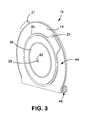
- FIG. 3is a front perspective view of the first embodiment of FIG. 1 .
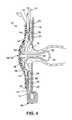
- FIG. 4is a schematic sectional view of the first embodiment in a fitted and deployed condition.
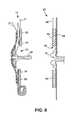
- FIG. 5is a schematic sectional view of the removal of the first embodiment.
- FIG. 6is a schematic sectional view of a second embodiment of the invention in the form of a two-piece appliance.
- FIG. 7is a schematic sectional view of a first possible modification of the stoma seal used in the preferred embodiments.
- FIG. 8is a schematic sectional view of a second possible modification of the stoma seal used in the preferred embodiments.
- a first embodimentillustrates a controlled evacuation ostomy appliance in the form of a pouch 10 as a body waste collector.
- the pouch 10generally comprises an envelope defined by two walls, a first, rear wall 12 and a second, front wall 14 .
- the walls 12 , 14may be formed from separate sheets secured together around their mutual periphery, or from a single sheet of material that is folded and secured around its edges to define an envelope shape.
- Each wall 12 , 14may be made of any suitable flexible sheet or film material, such as a laminate including at least one layer of ethylene vinyl acetate (EVA) and at least one gas barrier layer, such as poly(vinylidene chloride) PVDC.
- EVAethylene vinyl acetate
- PVDCpoly(vinylidene chloride)
- the rear wall 12comprises, in its upper region, a stomal aperture 16 for fitting around a stoma 18 ( FIG. 4 ) in use.
- a first (outer) coupling element 20is attached to the rear wall 12 around the stomal aperture 16 .
- the outer coupling element 20is an adhesive coupling element, including a closed-loop shaped substrate (e.g., a foam tape) carrying adhesive.
- the outer coupling element 20includes a first manipulation tab 21 for facilitating manipulation of the pouch 10 .
- the first manipulation tab 21is associated with the outer coupling element 20 and/or with the rear wall 12 .
- the first manipulation tab 21may be integral with the substrate of the outer coupling element 20 .
- the first embodimentis a one-piece appliance, in which the pouch 10 is directly coupled to the peristomal skin.
- the adhesive of the first coupling element 20is of a skin-compatible type.
- the pouch 10further comprises a stoma seal 22 that is carried by and/or coupled to, the front wall 14 .
- the stoma seal 22is positioned generally in register with the stomal aperture 16 .
- the stoma seal 22is mounted on the external (or front) side of the front wall 14 , and projects through a second aperture 23 in the front wall 14 into the pouch 10 interior.
- the stoma seal 22could be mounted on the interior face of the front wall 14 .
- the stoma seal 22projects through the stomal aperture 16 so that the distal end of the stoma seal 22 projects through the rear of the pouch 10 .
- the stoma seal 22may take any suitable form for sealing against the inner and/or outer surface of the stoma 18 .
- the stoma seal 22is configured to be (i) of an inflatable type, and (ii) of a type that is inserted into the stoma 18 to seal against the internal tissue behind the stoma 18 .
- the stoma seal 22generally comprises at least one membrane 25 that defines an inflatable balloon 24 arranged around a tube 26 .
- the membrane 25may be thermoformed into a generally tubular and/or bulbous shape. Such a shape may also be formed by gusseting the membrane material.
- the tube 26is made of a generally soft, flexible material, such as silicone rubber.
- the tube 26has one or both of the following functions: (i) an inserter guide for facilitating insertion of the inflatable balloon 24 into the stoma 18 when the inflatable balloon 24 is in a deflated condition; and (ii) for delivering inflation fluid to the inflatable balloon 24 from an inflation port 28 .
- the tube 26is open at its distal end, and may also have openings (not shown) along its length.
- the tube 26is fitted, at its proximal end, with an inflation valve 30 defining the inflation port 28 .
- the inflation valve 30is configured to admit inflation fluid (such as air or saline) when injected by a user, and for preventing escape of the inflation fluid, at least until desired by the ostomate.
- the pouch 10further comprises a stoma seal support for supporting the stoma seal 22 .
- the stoma seal supportcomprises one or more of the following elements: a second (inner) coupling element 34 , a relatively rigid housing 36 , and foam 38 .
- the inner coupling element 34is disposed at the stomal aperture 16 inwardly of the outer coupling element 20 .
- a periphery of the inner coupling element 34is surrounded by the outer coupling element 20 .
- the outer and inner coupling elements 20 , 34may be formed integrally together from a common substrate piece.
- the two coupling elements 20 , 34may be stamped from a single piece of material.
- the outer and inner coupling elements 20 , 34may be coupled together by frangible connections 39 so that, at least initially, the outer and inner coupling elements 20 and 34 are generally coplanar.
- the adhesive surfaces of the two coupling elements 20 and 34may be protected by a removable release sheet 40 , for example, a plastics sheet coated with a suitable release material such as silicone.
- the housing 36is secured to the outer face of the front wall 14 around the second aperture 23 .
- the proximal end of the tube 26 and/or the inflation port 28is anchored to the housing 36 at an aperture 42 .
- the housing 36is made of a material that is more rigid than the pouch walls 12 , 14 , but may also be resiliently flexible.
- the housing 36may have a three-dimensional shape that helps its rigidity, such as a dome shape.
- the housing 36 (and the foam 38 )supports the stoma seal 22 with respect to the front wall 14 .
- the front wall 14is itself supported in the region of the stomal aperture 16 by means of the inner coupling element 34 , thereby supporting the housing 36 and the stoma seal 22 .
- a second manipulation tab 37 carried on a collar 35is attached to the housing 36 for applying a force to distend the pouch to permit a discharge of body waste, as described later below.
- the second manipulation tab 37is associated with the front wall 14 and/or with the inner coupling member 34 .
- the first and second manipulation tabs 21 , 37may be disposed at different angular orientations ( FIGS. 2 and 3 ), to allow easy access using a different hand to hold each tab.
- the foam 38is disposed between the membrane 25 and the housing 36 .
- the foam 38is of a soft compressible type to provide a cushion between the relatively rigid housing 36 and the membrane 25 , and thus prevent discomfort to the stoma 18 .
- an intermediate, annular shaped portion 14 a of the front wall 14optionally exists between the points at which the front wall 14 is fastened to (i) the inner coupling element 34 and (ii) the housing 36 .
- the intermediate portion 14 aprovides a degree of limited floating movement between the inner coupling element 34 and the housing 36 .
- This floating movementin combination with the foam 38 , provides a degree of decoupling so that the relatively rigid housing 36 does not, in use, cause discomfort to the stoma 18 , even if an external force is accidentally applied to the housing 36 .
- the housing 36 or the stoma seal 22may be directly attached to the inner coupling element 34 without such floating movement.
- the pouch 10may have any desired shape or profile.
- the pouch 10generally has a “keyhole” shaped profile.
- the pouch 10has an upper rounded or bulbous portion 44 at which the stomal aperture 16 and the coupling elements 20 , 34 are located, and from which depends a lower collection portion 46 .
- the lower collection portion 46may have a (maximum) transverse dimension smaller than the maximum transverse dimension of the upper rounded portion 44 .
- the lower collection portion 46is rolled or folded into a compact configuration, to reduce the size of the pouch 10 .
- the lower collection portion 46may be rolled up to the upper rounded portion 44 , and secured in position by means of a pressure sensitive adhesive region 48 on one wall 12 of the pouch 10 .
- hook-hook or hook-loop fastenersmay be used instead of adhesive if desired, or a flap or sling (not shown) may wrap around or under the rolled-up lower collection portion 46 to hold it in its compact condition.
- a flap or slingmay wrap around or under the rolled-up lower collection portion 46 to hold it in its compact condition.
- an external clipmay be used to hold the lower collection portion 46 in its compact condition.
- the pouch 10is a closed pouch, and the lower collection portion 46 is completely closed.
- the pouch 10may be of a drainable type, and the lower collection portion 46 may include a drain aperture, such as a drain chute (not shown) or a drain tap (not shown).
- the pouch 10Prior to use, the pouch 10 generally has the configuration shown in FIG. 1 .
- the arrangement of the outer and inner coupling elements 20 , 34keeps the pouch 10 generally flat, and presents the deflated balloon 24 of the stoma seal 22 at the stoma aperture 16 .
- the stoma seal 22is generally presented at position suitable for cooperating with the stoma 18 .
- the outer and inner coupling elements 20 , 34are retained generally co-planar by one or both of: (i) the frangible connections 39 ; and (ii) the adhesion of both coupling elements 20 , 34 to the release sheet 40 (although such adhesion may be relatively weak).
- a first stageis to align the pouch 10 with respect to the stoma 18 , to insert the distal end of the deflated balloon 24 of the stoma seal 22 into the stoma 18 .
- the tube 26acts as a guide or introducer for this purpose.
- the deflated balloon 24collapses around the tube 26 , and the tube 26 enables the balloon 24 to be easily slid into the stoma 18 .
- the softness and flexibility of the tube 26ensures that the tube 26 does not itself irritate or damage the stoma tissue.
- the membrane material 25may be coated with a lubricant and/or the material may be inherently lubricious.
- the degree of projection of the tube 26 from the stomal aperture 16can ensure that the user can view the alignment easily, and that the pouch 10 does not obscure the user's view.
- the next stageis to press the pouch 10 towards the body, so that the balloon 24 fully enters the stoma 18 , and the coupling elements 20 , 34 contact the wearer's peristomal skin.
- the co-planarity of the outer and inner coupling elements 20 , 34can ensure that, although the inner coupling element 34 may be entirely surrounded by the outer coupling element 20 , the inner coupling element 34 can contact the peristomal skin as equally securely as the outer coupling element 20 .
- the usermay press the housing 36 to apply additional pressure to the inner coupling element 34 in order to ensure good adhesive contact.
- the foam 38 between the housing 36 and the stoma seal 22avoids pressure applied to the housing 36 from being applied directly to the stoma 18 ; such pressure could be uncomfortable for the ostomate.
- the final stage( FIG. 4 ) is for the user to inflate the balloon 24 of the stoma seal 22 .
- the usercan insert a source of inflation fluid, such as a pump or syringe, into the inflation port 28 , in order to inject the inflation fluid to a desired inflation pressure.
- the inflated balloon 24presses against the internal tissue of the stoma 18 , to effect a seal against discharge of body waste.
- the inner coupling element 34in combination with the housing 36 , provides support for the stoma seal 22 .
- the inner coupling element 34 and the housing 36resist any tendency for the balloon 24 to be ejected from the stoma 18 , for example, by gas or body waste accumulating against the distal end of the balloon 24 .
- the balloon 24does not have to be inflated to a very high pressure, since the balloon 24 is supported externally.
- the inflation pressuremerely has to be moderate to enable an effective seal against leakage of body waste past the balloon 24 .
- the inflation pressureitself does not have to frictionally hold the balloon 24 inside the stoma 18 .
- the balloon 24may be engineered to permit venting of flatus through or around the balloon 24 to avoid discomfort that may be caused by accumulation of flatus in the intestine.
- Flatus venting past or through the stoma seal 22may be deodorized by means of a deodorizing filter 52 .
- the filter 52is conveniently located inside the housing 36 , and may be accommodated in a recess of pocket 54 of the foam 38 .
- Flatusenters the filter 52 either through the foam 38 and/or through one or more flatus passages (not shown) provided through the membrane 25 and or through the tube 26 .
- Such passagesmay comprise microporous apertures or perforations in the membrane 25 , for example, in a non-inflatable part of the membrane 25 .
- the aperturescan be formed by laser. The size of the apertures may be from about 0.005 mm to about 0.5 mm.
- the outlet side of the filter 52may communicate with the aperture 42 for discharging the deodorized flatus to the external atmosphere.
- additional outlet aperturesmay be provided in the housing 36 , such apertures having a size of from about 0.1 mm to about 2 mm.
- the filter 52may also serve to deodorize odors from body waste collected later in the pouch 10 when the stoma seal 22 is deactivated to permit a discharge.
- the collection portion 46 of the pouchmay remain in its compact condition, such that the pouch 10 occupies very little space.
- the pouch 10can form a snug fit against the body, and can be worn under most clothing without being obtrusive.
- the provision of the inner coupling element 34keeps the front wall 14 of the pouch 10 close to the rear wall 12 , and close to skin level.
- the majority of the structureis made of flexible and low-profile material, giving the appliance a very low profile not substantially more obtrusive than a simple open pouch.
- the only significant rigid portion of the applianceis the housing 36 , but this can be made of material that is resiliently flexible while having a generally self-supporting shape.
- the userwhen the user desires to discharge body waste, the user first manipulates the inflation valve 30 at the inflation port 28 to vent the inflation fluid. This permits the balloon 24 to collapse out of sealing engagement with the stoma tissue. Thereafter, the user distends the upper portion 44 of the pouch 10 , in order to withdraw the stoma seal 22 substantially from the stoma 18 , and permit discharge of body waste into the pouch 10 .
- the userpulls on the second manipulation tab 37 with one hand (arrow 50 a ), while gripping the first manipulation tab 21 with the other hand (arrow 50 b ), in order to stabilize the pouch 10 .
- the relative geometry of the housing 36 and the inner coupling element 34is such that force applied from the second manipulation tab 37 is applied in a direction to peel the inner coupling element 34 progressively.
- the peeling forceis applied from the housing 36 through the intermediate wall portion 14 a to the outer edge of the inner coupling element 34 .
- the peeling motionalso causes the frangible connections 39 to severe progressively, allowing the inner coupling element 34 to separate from the outer coupling element 20 .
- the front wall 14 of the pouch 10displaces away from the rear wall 12 (arrow 50 c ), thereby withdrawing the stoma seal 22 from the stoma 18 .
- the stoma seal 22may either be completely withdrawn from the stoma 18 , or the distal end of the seal 22 may partly remain inside the mouth of the stoma 18 , where it does not substantially obstruct stomal discharge of body waste into the pouch 10 .
- the flexibility of the tube 26 and/or the membrane 25 defining the inflatable balloon 24can ensure that these items can be pushed aside by the exiting body waste.
- the usermay manually extend the lower collection portion 46 of the pouch 10 , or the lower collection portion 46 may extend automatically under the weight of body waste entering the pouch 10 and falling into the lower collection portion 46 .
- a significant advantage of the inventionis that the user does not have to insert his or hand into the interior of the pouch 10 in order to deactivate the stoma seal 22 .
- the stoma seal 22can be deactivated and withdrawn merely by manipulation of the second manipulation tab 37 on the front wall 14 .
- An additional important effect of providing the second manipulation tab 37 attached to the front wall 14is that the user manually distends the upper portion 44 of the pouch 10 when effecting a discharge. This can avoid any problem of “pancaking”, which sometimes occurs when the internal surfaces of the front and rear walls 12 , 14 stick together. By manually distending the upper portion 44 of the pouch 10 , the user ensures that stomal discharge can freely enter the pouch.
- the pouch 10may be intended for a single-sealing use, or for multiple-sealing uses.
- a single-sealing usemay be appropriate if the stoma seal 22 is not intended to be resealed into the stoma 18 , for example, if the stoma seal 22 has a limited seal life or is not intended to be re-inflated multiple times.
- a multiple-sealing usemay be appropriate if the stoma seal 22 is of a more substantial type that can be resealed and/or re-inflated reliably.
- the usermay re-engage the stoma seal 22 without having to (i) remove the pouch 10 , nor (ii) insert his or her hand into the pouch interior. Instead, the user can manipulate the stoma seal 22 by means of the second manipulation tab 37 , to guide the stoma seal 22 back into the stoma 18 .
- the usermay also press against the housing 36 in order to press the inner coupling element 34 into firm adhesive engagement with the skin.
- the foam 38can ensure that application of such pressure through the housing 36 does not cause any discomfort to the stoma 18 itself. Thereafter, the user may re-inflate the balloon 24 of the stoma seal 22 in the same manner as described previously.
- the usergrips the first manipulation tab 21 to peel the outer coupling element 20 out of adhesive engagement with the skin.
- FIG. 6illustrates a second embodiment of the invention in the form of a two-piece appliance.
- the pouch 10has the same construction as the first embodiment.
- the main difference in the second embodimentis that the outer and inner coupling elements 20 , 34 do not directly contact the peristomal skin. Instead, a separate body wafer or body fitment 60 is provided for attachment to the skin.
- the body fitmentcomprises a third aperture 62 , a pad of skin compatible adhesive 64 for attachment to the skin, and a landing surface 66 to which the outer and inner coupling elements 20 , 34 of the pouch 10 can adhere.
- the material of the landing surface 66 and the adhesive 64 of the outer and inner coupling elements 20 , 34are such to enable peelable and re-sealable adhesion.
- the body fitment 60further comprises one or more additional manipulation tabs, such as a third manipulation tab 68 .
- the use of the pouch 10 of the second embodimentis similar to that of the first embodiment, except that the body fitment 60 remains attached to the ostomate when the pouch 10 is removed.
- the third manipulation tab 68is used by the ostomate to stabilize the body fitment 60 on the body whenever the outer coupling element 20 or the inner coupling element 34 is to be peeled from the body fitment 60 .
- the userwould grip the second manipulation tab 37 to apply the distension force with one hand, while gripping the third manipulation tab 68 with the other hand to ensure that the body fitment 60 remains firmly attached to the body.
- the adhesive 64 for the outer and inner coupling elements 20 , 34could be provided on the body fitment 60 instead of on the pouch 10 , if desired.
- the outer and inner coupling elements 20 , 34may then just be substrates for contacting the adhesive surface of the body fitment 60 .
- the outer and inner coupling elements 20 , 34use adhesive 64 to form a releasable coupling.
- the coupling between the body fitment 60 and one or both of the coupling elements 20 , 34may be mechanical instead of adhesive.
- the outer and inner coupling elements 20 , 34may each comprise a mechanical engagement profile for forming a releasable mechanical engagement with a complementary profile on the body fitment 60 .
- an external source of inflation fluidis used to inject inflation fluid for inflating the balloon 24 .
- the pouch 10may include an integral supply of inflation fluid, such as a bulb or concertina pump containing inflation fluid.
- the stoma seal 22is inflatable.
- the inventionalso contemplates a stoma seal 22 that may be non-inflatable.
- FIG. 7illustrates a non-inflatable stoma seal 70 , comprising a bolster or plug 72 of a soft compressible material, such as a foam 38 .
- the plug 72may be covered by a flexible film material 74 that contacts the stoma tissue.
- the plug 72may be integral with the foam 38 that is arranged in the housing 36 .
- the non-inflatable seal 70is shaped for insertion into the stoma 18 in the same way as the stoma seal 22 described previously, except that no inflation or deflation of the stoma seal 70 is involved.
- the stoma seal 70is deactivated by withdrawal from the stoma 18 when the second manipulation tab 37 is pulled to move the front wall 14 of the pouch 10 in a direction away from the rear wall 12 and the stoma 18 .
- the foam 39 which is used as the non-inflatable stoma seal 22can incorporate with particles of activated carbon such that the activated carbon containing foam has the ability to deodorize.
- Another example of a non-inflatable stoma sealis a tampon-like plug.
- an introducer to push the tampon inside of stoma 18can be employed.
- the membrane layer 74FIG. 7
- open cell foam and closed cell foamcan be used without the presence of the film 25 in FIG. 4 or film 74 in FIG. 7 , including hydrophilic foam.
- the hardness of the foamis preferably less than 60 Shore A.
- the walls of film membrane 27 in FIG. 4 , the walls of film membrane 74 in FIG. 7 , and the plug 72 shown in FIG. 7can be coated with adhesives to enhance the sealing, including hydrocolloid adhesives, mucoadhesives, and other adhesives that are shown to be safe and effective in sealing directly to mucosa membranes.
- the stoma seal 22 / 70is configured to enter the stoma 18 , in order to form a seal against the internal tissue of the stoma 18 .
- Such a sealcan be advantageous for a low profile appliance, because the seal need not occupy substantial space outside the stoma 18 .
- the inventionalso contemplates a stoma seal 22 / 70 that is substantially non-entrant into the stoma 18 .
- FIG. 8illustrates a stoma seal 22 / 70 in the form of a non-entrant stoma occluder 80 for sealing against the exterior tissue of a stoma.
- the stoma occludergenerally comprises a diaphragm or membrane 82 that is urged against the stoma 18 .
- the membrane 82may be urged by any suitable means, for example, by an inflatable balloon 84 , or by a resilient foam member (also depicted by numeral 84 ), or by a tensioner for applying tension indicated by arrows 86 .
- an applianceis described using a body waste collector in the form a pouch, other shapes and configurations of collector may be used as desired.
Landscapes
- Health & Medical Sciences (AREA)
- Veterinary Medicine (AREA)
- Public Health (AREA)
- General Health & Medical Sciences (AREA)
- Animal Behavior & Ethology (AREA)
- Life Sciences & Earth Sciences (AREA)
- Heart & Thoracic Surgery (AREA)
- Vascular Medicine (AREA)
- Biomedical Technology (AREA)
- Engineering & Computer Science (AREA)
- Orthopedic Medicine & Surgery (AREA)
- Nursing (AREA)
- Epidemiology (AREA)
- Chemical & Material Sciences (AREA)
- Oncology (AREA)
- Communicable Diseases (AREA)
- Chemical Kinetics & Catalysis (AREA)
- General Chemical & Material Sciences (AREA)
- Medicinal Chemistry (AREA)
- Nuclear Medicine, Radiotherapy & Molecular Imaging (AREA)
- Organic Chemistry (AREA)
- Pharmacology & Pharmacy (AREA)
- Orthopedics, Nursing, And Contraception (AREA)
- Acyclic And Carbocyclic Compounds In Medicinal Compositions (AREA)
- Materials For Medical Uses (AREA)
Abstract
Description
Claims (39)
Priority Applications (1)
| Application Number | Priority Date | Filing Date | Title |
|---|---|---|---|
| US12/599,791US9707120B2 (en) | 2007-05-11 | 2008-05-09 | Ostomy appliance |
Applications Claiming Priority (3)
| Application Number | Priority Date | Filing Date | Title |
|---|---|---|---|
| US91733407P | 2007-05-11 | 2007-05-11 | |
| PCT/US2008/063244WO2008141180A1 (en) | 2007-05-11 | 2008-05-09 | Ostomy appliance |
| US12/599,791US9707120B2 (en) | 2007-05-11 | 2008-05-09 | Ostomy appliance |
Related Parent Applications (1)
| Application Number | Title | Priority Date | Filing Date |
|---|---|---|---|
| PCT/US2008/063244A-371-Of-InternationalWO2008141180A1 (en) | 2007-05-11 | 2008-05-09 | Ostomy appliance |
Related Child Applications (1)
| Application Number | Title | Priority Date | Filing Date |
|---|---|---|---|
| US15/650,736ContinuationUS20170312115A1 (en) | 2007-05-11 | 2017-07-14 | Ostomy appliance |
Publications (2)
| Publication Number | Publication Date |
|---|---|
| US20100241092A1 US20100241092A1 (en) | 2010-09-23 |
| US9707120B2true US9707120B2 (en) | 2017-07-18 |
Family
ID=40002614
Family Applications (3)
| Application Number | Title | Priority Date | Filing Date |
|---|---|---|---|
| US12/599,791Expired - Fee RelatedUS9707120B2 (en) | 2007-05-11 | 2008-05-09 | Ostomy appliance |
| US12/152,037AbandonedUS20090156638A1 (en) | 2007-05-11 | 2008-05-12 | Uses of nordihydroguaiaretic acid (NDGA) and derivatives thereof in preventing transmission of sexually transmitted diseases |
| US15/650,736AbandonedUS20170312115A1 (en) | 2007-05-11 | 2017-07-14 | Ostomy appliance |
Family Applications After (2)
| Application Number | Title | Priority Date | Filing Date |
|---|---|---|---|
| US12/152,037AbandonedUS20090156638A1 (en) | 2007-05-11 | 2008-05-12 | Uses of nordihydroguaiaretic acid (NDGA) and derivatives thereof in preventing transmission of sexually transmitted diseases |
| US15/650,736AbandonedUS20170312115A1 (en) | 2007-05-11 | 2017-07-14 | Ostomy appliance |
Country Status (14)
| Country | Link |
|---|---|
| US (3) | US9707120B2 (en) |
| EP (1) | EP2150218B1 (en) |
| JP (1) | JP5474766B2 (en) |
| AU (1) | AU2008251471B2 (en) |
| CA (1) | CA2687080C (en) |
| DK (1) | DK2150218T3 (en) |
| ES (1) | ES2588235T3 (en) |
| HR (1) | HRP20161017T1 (en) |
| HU (1) | HUE029409T2 (en) |
| MX (1) | MX343303B (en) |
| NZ (1) | NZ581837A (en) |
| PL (1) | PL2150218T3 (en) |
| PT (1) | PT2150218T (en) |
| WO (1) | WO2008141180A1 (en) |
Cited By (11)
| Publication number | Priority date | Publication date | Assignee | Title |
|---|---|---|---|---|
| US10238528B1 (en)* | 2018-02-21 | 2019-03-26 | Dmitri Alden | Method and device for the management of body fluids leaking from a surgical drain tube incision |
| US20190175386A1 (en)* | 2016-06-07 | 2019-06-13 | Stephanie MONTY | Dressing for concealing a structure on a human body |
| US10456289B2 (en)* | 2018-02-21 | 2019-10-29 | Alden Advanced Technologies, Inc. | Method and device for the management of body fluids leaking from a surgical drain tube incision |
| US20200093632A1 (en)* | 2014-01-28 | 2020-03-26 | Hollister Incorporated | Ostomy faceplate including invertible stoma collar |
| WO2019164693A3 (en)* | 2018-02-21 | 2020-05-07 | Dmitri Alden | Method and device for the management of body fluids leaking from a surgical drain tube incision |
| US11191662B2 (en)* | 2015-11-06 | 2021-12-07 | Avent, Inc. | Ostomy device, apparatus, and system |
| US20220054294A1 (en)* | 2010-09-30 | 2022-02-24 | Convatec Technologies Inc. | Ostomy pouch with filtering system |
| US20220202606A1 (en)* | 2020-12-31 | 2022-06-30 | Convatec Technologies Inc. | Coupling system for ostomy appliances |
| US11883317B2 (en)* | 2020-04-15 | 2024-01-30 | Convatec Limited | Ostomy appliance |
| US12419997B2 (en) | 2018-05-14 | 2025-09-23 | The Penn State Research Foundation | Ostomy bag with a slippery surface |
| US12440369B2 (en)* | 2020-04-15 | 2025-10-14 | Convatec Limited | Ostomy appliance |
Families Citing this family (35)
| Publication number | Priority date | Publication date | Assignee | Title |
|---|---|---|---|---|
| EP2120815A2 (en)* | 2007-03-07 | 2009-11-25 | ConvaTec Technologies Inc. | Ostomy devices with mucoadhesives |
| CA2687080C (en)* | 2007-05-11 | 2016-06-28 | Convatec Technologies Inc. | Ostomy appliance |
| JP5474779B2 (en)* | 2007-06-12 | 2014-04-16 | コンバテック・テクノロジーズ・インコーポレイテッド | Ostomy device |
| CN102215791A (en) | 2008-11-19 | 2011-10-12 | 康沃特克科技公司 | Ostomy pocket appliance |
| CN102481201B (en) | 2009-07-14 | 2016-03-09 | 斯提马提克斯Gi有限公司 | Ostomy containment device |
| US8821464B2 (en) | 2009-07-14 | 2014-09-02 | Stimatix Gi Ltd. | Disposable ostomy assemblies |
| WO2011138727A1 (en)* | 2010-05-02 | 2011-11-10 | Stimatix Gi Ltd. | Ostomy port gas release mechanism |
| US8900116B2 (en) | 2009-07-14 | 2014-12-02 | Stimatix Gi Ltd. | Inflatable stomal implant |
| IN2012DN01988A (en) | 2009-09-11 | 2015-07-24 | Convatec Technologies Inc | |
| US10285847B2 (en)* | 2011-09-29 | 2019-05-14 | Convatec Technologies Inc. | Ostomy pouch with filtering system |
| US8684982B2 (en)* | 2010-10-29 | 2014-04-01 | Convatec Technologies Inc. | Controlled evacuation ostomy appliance |
| US8460259B2 (en)* | 2010-11-02 | 2013-06-11 | Convatec Technologies, Inc. | Controlled discharge ostomy appliance and moldable adhesive wafer |
| DE102012105856A1 (en)* | 2011-09-30 | 2013-04-04 | Arpad Dani | ostomy appliance |
| US20130253455A1 (en)* | 2012-03-22 | 2013-09-26 | Hollister Incorporated | Expandable ostomy appliance |
| BR112014028052A2 (en) | 2012-05-10 | 2020-10-27 | Stimatix Gi Ltd | ostomy apparatus, ostomy component sealing system, and method of sealing the stoma in an individual's body. |
| WO2014181338A2 (en) | 2013-05-09 | 2014-11-13 | Stimatix Gi Ltd. | Compact ostomy appliance |
| CA2918740C (en) | 2013-07-23 | 2021-08-17 | Convatec Technologies Inc. | Moldable adhesive wafers |
| US20150094675A1 (en)* | 2013-10-01 | 2015-04-02 | Tidi Securement Products, Llc | Stoma Stopper Securement Dressing |
| USD783814S1 (en) | 2013-12-09 | 2017-04-11 | B. Braun Medical Sas | Adapter for flatus release |
| USD796029S1 (en) | 2013-12-09 | 2017-08-29 | B. Braun Medical Sas | Colostomy appliance |
| US20150290024A1 (en)* | 2014-04-14 | 2015-10-15 | Achilles Nassopoulos | Reusable ostomy pouch value |
| DK3134040T3 (en) | 2014-04-24 | 2021-05-25 | Convatec Technologies Inc | Ostomy bag filter system |
| NL2013602B1 (en)* | 2014-10-09 | 2016-09-01 | Stomydo B V | Device for cleaning a stoma in a human or animal body. |
| CN107206118A (en)* | 2015-01-28 | 2017-09-26 | 霍利斯特股份有限公司 | For the stoma edge device for moistening the adhesive of tissue and being made using the adhesive |
| RU2721076C2 (en)* | 2015-10-20 | 2020-05-15 | Колопласт А/С | Stoma apparatus |
| US10799560B2 (en) | 2016-03-25 | 2020-10-13 | Periphagen, Inc. | HSV vectors for delivery of NT3 and treatment of CIPN |
| WO2017165813A1 (en) | 2016-03-25 | 2017-09-28 | Periphagen, Inc. | High-transducing hsv vectors |
| US12178738B2 (en) | 2018-01-19 | 2024-12-31 | Ostovalve Llc | Regulating flow from a stoma on a patient |
| US11771585B2 (en) | 2018-01-19 | 2023-10-03 | Ostovalve, Llc | Devices, systems and methods for regulating flow from a stoma on a patient |
| USD1012280S1 (en) | 2018-11-30 | 2024-01-23 | B. Braun Medical Sas | Ostomy device assembly |
| WO2021188061A1 (en)* | 2020-03-16 | 2021-09-23 | Tekeli Onur | A urinary system making the involuntary excretion occuring after colostomy, ileostomy and urostomy voluntary |
| EP4267054B1 (en)* | 2020-12-23 | 2025-05-07 | Coloplast A/S | An adhesive ostomy product securing member |
| EP4280875A4 (en)* | 2021-01-19 | 2024-05-29 | Erimos Pharmaceuticals LLC | Terameprocol and nordihydroguaiaretic acid (ndga) derivatives as coronavirus anti-viral agents |
| JP2024536643A (en)* | 2021-10-22 | 2024-10-04 | オストバルブ エルエルシー | DEVICES, SYSTEMS AND METHODS FOR CONTROLLING FLOW FROM A STOMAS IN A PATIENT - Patent application |
| WO2024105726A1 (en)* | 2022-11-14 | 2024-05-23 | 株式会社Eudaimonix | Colostomy device |
Citations (33)
| Publication number | Priority date | Publication date | Assignee | Title |
|---|---|---|---|---|
| US2684675A (en) | 1951-09-10 | 1954-07-27 | Perry Murle | Stoma receiver of simplified construction for use with a disposable bag |
| US3884242A (en) | 1971-03-29 | 1975-05-20 | Mpc Kurgisil | Catheter assembly |
| US3938521A (en)* | 1972-06-22 | 1976-02-17 | M.E.D.S. Corporation | Collecting bag |
| US4050461A (en) | 1976-04-23 | 1977-09-27 | Ruby Max H | Stoma irrigation system |
| US4137918A (en)* | 1975-12-18 | 1979-02-06 | Clayton Bogert | Medical by-pass device for use after ostomy surgery |
| US4209009A (en) | 1977-05-17 | 1980-06-24 | Gerhard Hennig | Anus closure tampon and method of manufacture |
| US4210131A (en)* | 1978-07-26 | 1980-07-01 | The Kendall Company | Artificial sphincter with collection bag |
| US4406657A (en) | 1980-04-04 | 1983-09-27 | Laboratoires Biotrol S.A. | Noise-attenuating device for colostomy |
| US4411659A (en) | 1982-03-16 | 1983-10-25 | Hollister Incorporated | Drainable collection pouch and filter assembly therefor |
| US4701169A (en) | 1983-12-19 | 1987-10-20 | Craig Medical Products | Ostomy appliance with improved attachment means |
| US4710182A (en)* | 1986-12-04 | 1987-12-01 | Hollister Incorporated | Ostomy appliance and method of making |
| US4941869A (en) | 1988-10-17 | 1990-07-17 | Amico Ben A D | Ostomy plug-pouch |
| US4950223A (en)* | 1985-09-05 | 1990-08-21 | Trimark (R&D) Limited | Stoma closure devices |
| US5269774A (en)* | 1992-09-25 | 1993-12-14 | Gray Michael W | Implantive ostomy ring |
| US5935115A (en) | 1997-03-27 | 1999-08-10 | Saint Margaret Mercy Healthcare Centers, Inc. | Suprapubic catheter leak collection device |
| US6050982A (en)* | 1997-11-03 | 2000-04-18 | Wheeler; Alton D. | Concealed colostomy apparatus and method |
| US6050983A (en) | 1998-10-27 | 2000-04-18 | Moore; Diane | Sound-insulated gas-diverting colostomy container |
| US6569081B1 (en) | 1999-02-10 | 2003-05-27 | Coloplast A/S | Ostomy plug |
| US6689111B2 (en)* | 2002-03-22 | 2004-02-10 | Bristol-Myers Squibb Company | Controlled evacuation ostomy device with internal seal |
| US20050075616A1 (en)* | 2003-10-02 | 2005-04-07 | Holter Dwight Jerome | Ostomy tools, and systems and processes for their use |
| US20050177119A1 (en)* | 2004-01-21 | 2005-08-11 | Tsai M. L. | Pouch for medical use |
| US20060058577A1 (en) | 2004-09-16 | 2006-03-16 | Bristol-Myers Squibb Company | Seal for controlled evacuation ostomy appliance |
| US20060069380A1 (en)* | 2004-09-30 | 2006-03-30 | Fung-Jou Chen | Foam-based fasteners |
| US20060206069A1 (en)* | 2002-03-27 | 2006-09-14 | Cline John B | Controlled evacuation ostomy device with external seal |
| US20070021651A1 (en)* | 2003-07-23 | 2007-01-25 | Lothar Gobel | Closing system for a natural or an artificial anus |
| US7258661B2 (en)* | 2004-09-13 | 2007-08-21 | Bristol-Myers Squibb Company | Stoma plug |
| US20080269698A1 (en)* | 2007-04-25 | 2008-10-30 | Bristol-Myers Squibb Company | Ostomy appliance collector |
| WO2008141180A1 (en) | 2007-05-11 | 2008-11-20 | Bristol-Myers Squibb Company | Ostomy appliance |
| US20100022976A1 (en)* | 2007-02-22 | 2010-01-28 | Convatec Technologies Inc. | Seal for a rectal or ostomy appliance |
| US20120078208A1 (en)* | 2010-09-25 | 2012-03-29 | Laudick David A | Contained ostomy appliance |
| US20120283678A1 (en)* | 2010-10-29 | 2012-11-08 | Conva Tec Technologies Inc. | Controlled evacuation ostomy appliance |
| US8460259B2 (en)* | 2010-11-02 | 2013-06-11 | Convatec Technologies, Inc. | Controlled discharge ostomy appliance and moldable adhesive wafer |
| US20140148770A1 (en)* | 2011-08-09 | 2014-05-29 | Hollister Incorporated | Parachute ostomy pouch |
Family Cites Families (7)
| Publication number | Priority date | Publication date | Assignee | Title |
|---|---|---|---|---|
| JPS62258657A (en)* | 1986-05-06 | 1987-11-11 | 株式会社 東京衛材研究所 | Mount jig for artificial anus |
| US6365787B1 (en)* | 1994-09-30 | 2002-04-02 | The Johns Hopkins University | Compounds for the suppression of HIV TAT transactivation |
| US5865819A (en)* | 1997-06-27 | 1999-02-02 | Hollister Incorporated | Two-pouch ostomy appliance with separate inner and outer adhesive flanges |
| US6214874B1 (en)* | 1999-10-15 | 2001-04-10 | John Hopkins University | Treatment of HPV induced cancer using in situ application of two nordihydroguiaretic acid derivatives, tetramethyl NDGA M4N and tetraglycinal NDGA G4N |
| CA2502986C (en)* | 2002-10-25 | 2011-08-23 | Foamix Ltd. | Cosmetic and pharmaceutical foam |
| WO2005011567A2 (en)* | 2003-08-04 | 2005-02-10 | Foamix Ltd. | Foam carrier containing amphiphilic copolymeric gelling agent |
| US7741357B1 (en)* | 2006-04-17 | 2010-06-22 | Johns Hopkins University | Heterocyclic and carbonate derivatives of NDGA and their use as new anti-HIV and anti-cancer agents |
- 2008
- 2008-05-09CACA2687080Apatent/CA2687080C/ennot_activeExpired - Fee Related
- 2008-05-09ESES08755235.2Tpatent/ES2588235T3/enactiveActive
- 2008-05-09NZNZ581837Apatent/NZ581837A/ennot_activeIP Right Cessation
- 2008-05-09HRHRP20161017TTpatent/HRP20161017T1/enunknown
- 2008-05-09HUHUE08755235Apatent/HUE029409T2/enunknown
- 2008-05-09MXMX2009012223Apatent/MX343303B/enactiveIP Right Grant
- 2008-05-09WOPCT/US2008/063244patent/WO2008141180A1/enactiveApplication Filing
- 2008-05-09PLPL08755235.2Tpatent/PL2150218T3/enunknown
- 2008-05-09JPJP2010507695Apatent/JP5474766B2/ennot_activeExpired - Fee Related
- 2008-05-09AUAU2008251471Apatent/AU2008251471B2/ennot_activeCeased
- 2008-05-09PTPT87552352Tpatent/PT2150218T/enunknown
- 2008-05-09DKDK08755235.2Tpatent/DK2150218T3/enactive
- 2008-05-09EPEP08755235.2Apatent/EP2150218B1/enactiveActive
- 2008-05-09USUS12/599,791patent/US9707120B2/ennot_activeExpired - Fee Related
- 2008-05-12USUS12/152,037patent/US20090156638A1/ennot_activeAbandoned
- 2017
- 2017-07-14USUS15/650,736patent/US20170312115A1/ennot_activeAbandoned
Patent Citations (38)
| Publication number | Priority date | Publication date | Assignee | Title |
|---|---|---|---|---|
| US2684675A (en) | 1951-09-10 | 1954-07-27 | Perry Murle | Stoma receiver of simplified construction for use with a disposable bag |
| US3884242A (en) | 1971-03-29 | 1975-05-20 | Mpc Kurgisil | Catheter assembly |
| US3938521A (en)* | 1972-06-22 | 1976-02-17 | M.E.D.S. Corporation | Collecting bag |
| US4137918A (en)* | 1975-12-18 | 1979-02-06 | Clayton Bogert | Medical by-pass device for use after ostomy surgery |
| US4050461A (en) | 1976-04-23 | 1977-09-27 | Ruby Max H | Stoma irrigation system |
| US4209009A (en) | 1977-05-17 | 1980-06-24 | Gerhard Hennig | Anus closure tampon and method of manufacture |
| US4210131A (en)* | 1978-07-26 | 1980-07-01 | The Kendall Company | Artificial sphincter with collection bag |
| US4406657A (en) | 1980-04-04 | 1983-09-27 | Laboratoires Biotrol S.A. | Noise-attenuating device for colostomy |
| US4411659A (en) | 1982-03-16 | 1983-10-25 | Hollister Incorporated | Drainable collection pouch and filter assembly therefor |
| US4701169A (en) | 1983-12-19 | 1987-10-20 | Craig Medical Products | Ostomy appliance with improved attachment means |
| US4950223A (en)* | 1985-09-05 | 1990-08-21 | Trimark (R&D) Limited | Stoma closure devices |
| US4710182A (en)* | 1986-12-04 | 1987-12-01 | Hollister Incorporated | Ostomy appliance and method of making |
| US4941869A (en) | 1988-10-17 | 1990-07-17 | Amico Ben A D | Ostomy plug-pouch |
| US5269774A (en)* | 1992-09-25 | 1993-12-14 | Gray Michael W | Implantive ostomy ring |
| US5935115A (en) | 1997-03-27 | 1999-08-10 | Saint Margaret Mercy Healthcare Centers, Inc. | Suprapubic catheter leak collection device |
| US6050982A (en)* | 1997-11-03 | 2000-04-18 | Wheeler; Alton D. | Concealed colostomy apparatus and method |
| US6050983A (en) | 1998-10-27 | 2000-04-18 | Moore; Diane | Sound-insulated gas-diverting colostomy container |
| US6569081B1 (en) | 1999-02-10 | 2003-05-27 | Coloplast A/S | Ostomy plug |
| US6689111B2 (en)* | 2002-03-22 | 2004-02-10 | Bristol-Myers Squibb Company | Controlled evacuation ostomy device with internal seal |
| US8096980B2 (en)* | 2002-03-27 | 2012-01-17 | Convatec Technologies Inc. | Controlled evacuation ostomy device with external seal |
| US20060206069A1 (en)* | 2002-03-27 | 2006-09-14 | Cline John B | Controlled evacuation ostomy device with external seal |
| US20070021651A1 (en)* | 2003-07-23 | 2007-01-25 | Lothar Gobel | Closing system for a natural or an artificial anus |
| US20050075616A1 (en)* | 2003-10-02 | 2005-04-07 | Holter Dwight Jerome | Ostomy tools, and systems and processes for their use |
| US20050177119A1 (en)* | 2004-01-21 | 2005-08-11 | Tsai M. L. | Pouch for medical use |
| US7258661B2 (en)* | 2004-09-13 | 2007-08-21 | Bristol-Myers Squibb Company | Stoma plug |
| US20060058577A1 (en) | 2004-09-16 | 2006-03-16 | Bristol-Myers Squibb Company | Seal for controlled evacuation ostomy appliance |
| US20060069380A1 (en)* | 2004-09-30 | 2006-03-30 | Fung-Jou Chen | Foam-based fasteners |
| US20100069859A1 (en)* | 2007-02-22 | 2010-03-18 | Convatec Technologies Inc. | Seal for an ostomy appliance |
| US20100022976A1 (en)* | 2007-02-22 | 2010-01-28 | Convatec Technologies Inc. | Seal for a rectal or ostomy appliance |
| US8388586B2 (en)* | 2007-02-22 | 2013-03-05 | Convatec Technologies, Inc. | Seal for an ostomy appliance |
| US20080269698A1 (en)* | 2007-04-25 | 2008-10-30 | Bristol-Myers Squibb Company | Ostomy appliance collector |
| WO2008141180A1 (en) | 2007-05-11 | 2008-11-20 | Bristol-Myers Squibb Company | Ostomy appliance |
| US20100241092A1 (en)* | 2007-05-11 | 2010-09-23 | Convatec Technologies Inc. | Ostomy appliance |
| US20120078208A1 (en)* | 2010-09-25 | 2012-03-29 | Laudick David A | Contained ostomy appliance |
| US20120283678A1 (en)* | 2010-10-29 | 2012-11-08 | Conva Tec Technologies Inc. | Controlled evacuation ostomy appliance |
| US8684982B2 (en)* | 2010-10-29 | 2014-04-01 | Convatec Technologies Inc. | Controlled evacuation ostomy appliance |
| US8460259B2 (en)* | 2010-11-02 | 2013-06-11 | Convatec Technologies, Inc. | Controlled discharge ostomy appliance and moldable adhesive wafer |
| US20140148770A1 (en)* | 2011-08-09 | 2014-05-29 | Hollister Incorporated | Parachute ostomy pouch |
Cited By (15)
| Publication number | Priority date | Publication date | Assignee | Title |
|---|---|---|---|---|
| US20220054294A1 (en)* | 2010-09-30 | 2022-02-24 | Convatec Technologies Inc. | Ostomy pouch with filtering system |
| US11571325B2 (en)* | 2014-01-28 | 2023-02-07 | Hollister Incorporated | Ostomy faceplate including invertible stoma collar |
| US20200093632A1 (en)* | 2014-01-28 | 2020-03-26 | Hollister Incorporated | Ostomy faceplate including invertible stoma collar |
| US11191662B2 (en)* | 2015-11-06 | 2021-12-07 | Avent, Inc. | Ostomy device, apparatus, and system |
| US11229543B2 (en)* | 2015-11-06 | 2022-01-25 | Avent, Inc. | Ostomy device, apparatus, and system |
| US20190175386A1 (en)* | 2016-06-07 | 2019-06-13 | Stephanie MONTY | Dressing for concealing a structure on a human body |
| US11793663B2 (en)* | 2016-06-07 | 2023-10-24 | Ostique Limited | Dressing for concealing a structure on a human body |
| US10456289B2 (en)* | 2018-02-21 | 2019-10-29 | Alden Advanced Technologies, Inc. | Method and device for the management of body fluids leaking from a surgical drain tube incision |
| WO2019164693A3 (en)* | 2018-02-21 | 2020-05-07 | Dmitri Alden | Method and device for the management of body fluids leaking from a surgical drain tube incision |
| US10238528B1 (en)* | 2018-02-21 | 2019-03-26 | Dmitri Alden | Method and device for the management of body fluids leaking from a surgical drain tube incision |
| US12419997B2 (en) | 2018-05-14 | 2025-09-23 | The Penn State Research Foundation | Ostomy bag with a slippery surface |
| US11883317B2 (en)* | 2020-04-15 | 2024-01-30 | Convatec Limited | Ostomy appliance |
| US12440369B2 (en)* | 2020-04-15 | 2025-10-14 | Convatec Limited | Ostomy appliance |
| US12070410B2 (en)* | 2020-12-31 | 2024-08-27 | Convatec Technologies Inc. | Coupling system for ostomy appliances |
| US20220202606A1 (en)* | 2020-12-31 | 2022-06-30 | Convatec Technologies Inc. | Coupling system for ostomy appliances |
Also Published As
| Publication number | Publication date |
|---|---|
| AU2008251471B2 (en) | 2014-06-12 |
| NZ581837A (en) | 2012-08-31 |
| AU2008251471A1 (en) | 2008-11-20 |
| ES2588235T3 (en) | 2016-10-31 |
| MX2009012223A (en) | 2009-12-01 |
| US20100241092A1 (en) | 2010-09-23 |
| JP5474766B2 (en) | 2014-04-16 |
| DK2150218T3 (en) | 2016-09-05 |
| US20090156638A1 (en) | 2009-06-18 |
| HUE029409T2 (en) | 2017-02-28 |
| EP2150218A4 (en) | 2014-12-24 |
| MX343303B (en) | 2016-11-01 |
| JP2010526595A (en) | 2010-08-05 |
| CA2687080C (en) | 2016-06-28 |
| EP2150218A1 (en) | 2010-02-10 |
| WO2008141180A1 (en) | 2008-11-20 |
| CA2687080A1 (en) | 2008-11-20 |
| PL2150218T3 (en) | 2016-12-30 |
| EP2150218B1 (en) | 2016-07-27 |
| US20170312115A1 (en) | 2017-11-02 |
| PT2150218T (en) | 2016-08-30 |
| HRP20161017T1 (en) | 2016-10-21 |
Similar Documents
| Publication | Publication Date | Title |
|---|---|---|
| US9707120B2 (en) | Ostomy appliance | |
| EP1792590B1 (en) | Controlled evacuation ostomy appliance | |
| AU752540B2 (en) | Continent ostomy port | |
| EP1248580B1 (en) | Continent ostomy port | |
| US8388586B2 (en) | Seal for an ostomy appliance | |
| US6350255B1 (en) | Pad for use with a continent ostomy port | |
| US20020077611A1 (en) | Pad for use with continent ostomy port | |
| US20150141944A1 (en) | Ostomy appliance | |
| NZ524607A (en) | Internal balloon seal for ostomy stoma | |
| AU784678B2 (en) | Continent ostomy port |
Legal Events
| Date | Code | Title | Description |
|---|---|---|---|
| AS | Assignment | Owner name:CONVATEC TECHNOLOGIES INC., NEVADA Free format text:ASSIGNMENT OF ASSIGNORS INTEREST;ASSIGNOR:CONVATEC INC.;REEL/FRAME:023946/0096 Effective date:20081028 Owner name:CONVATEC INC., NEW JERSEY Free format text:ASSIGNMENT OF ASSIGNORS INTEREST;ASSIGNOR:BRISTOL-MYERS SQUIBB COMPANY;REEL/FRAME:023946/0075 Effective date:20080801 | |
| AS | Assignment | Owner name:JPMORGAN CHASE BANK, N.A., AS COLLATERAL AGENT, TEXAS Free format text:SECURITY AGREEMENT;ASSIGNOR:CONVATEC TECHNOLOGIES, INC.;REEL/FRAME:025591/0856 Effective date:20101222 Owner name:JPMORGAN CHASE BANK, N.A., AS COLLATERAL AGENT, TE Free format text:SECURITY AGREEMENT;ASSIGNOR:CONVATEC TECHNOLOGIES, INC.;REEL/FRAME:025591/0856 Effective date:20101222 | |
| AS | Assignment | Owner name:CONVATEC LIMITED, UNITED KINGDOM Free format text:RELEASE BY SECURED PARTY;ASSIGNOR:JPMORGAN CHASE BANK, N.A.;REEL/FRAME:040543/0357 Effective date:20161031 Owner name:UNOMEDICAL A/S, DENMARK Free format text:RELEASE BY SECURED PARTY;ASSIGNOR:JPMORGAN CHASE BANK, N.A.;REEL/FRAME:040543/0357 Effective date:20161031 Owner name:UNOMEDICAL LIMITED, UNITED KINGDOM Free format text:RELEASE BY SECURED PARTY;ASSIGNOR:JPMORGAN CHASE BANK, N.A.;REEL/FRAME:040543/0357 Effective date:20161031 Owner name:CONVATEC TECHNOLOGIES, INC., NEVADA Free format text:RELEASE BY SECURED PARTY;ASSIGNOR:JPMORGAN CHASE BANK, N.A.;REEL/FRAME:040543/0357 Effective date:20161031 | |
| AS | Assignment | Owner name:WILMINGTON TRUST (LONDON) LIMITED, AS COLLATERAL AGENT, UNITED KINGDOM Free format text:SECURITY AGREEMENT;ASSIGNORS:CONVATEC INC.;CONVATEC TECHNOLOGIES INC.;180 MEDICAL, INC.;AND OTHERS;REEL/FRAME:040552/0227 Effective date:20161031 Owner name:WILMINGTON TRUST (LONDON) LIMITED, AS COLLATERAL A Free format text:SECURITY AGREEMENT;ASSIGNORS:CONVATEC INC.;CONVATEC TECHNOLOGIES INC.;180 MEDICAL, INC.;AND OTHERS;REEL/FRAME:040552/0227 Effective date:20161031 | |
| AS | Assignment | Owner name:BRISTOL-MYERS SQUIBB COMPANY, NEW YORK Free format text:ASSIGNMENT OF ASSIGNORS INTEREST;ASSIGNORS:NGUYEN-DEMARY, TINH;TSAI, MINGLIANG LAWRENCE;REEL/FRAME:041771/0535 Effective date:20070628 | |
| STCF | Information on status: patent grant | Free format text:PATENTED CASE | |
| AS | Assignment | Owner name:CONVATEC TECHNOLOGIES INC., NEVADA Free format text:RELEASE BY SECURED PARTY;ASSIGNOR:WILMINGTON TRUST (LONDON) LIMITED;REEL/FRAME:050831/0001 Effective date:20191024 | |
| MAFP | Maintenance fee payment | Free format text:PAYMENT OF MAINTENANCE FEE, 4TH YEAR, LARGE ENTITY (ORIGINAL EVENT CODE: M1551); ENTITY STATUS OF PATENT OWNER: LARGE ENTITY Year of fee payment:4 | |
| FEPP | Fee payment procedure | Free format text:MAINTENANCE FEE REMINDER MAILED (ORIGINAL EVENT CODE: REM.); ENTITY STATUS OF PATENT OWNER: LARGE ENTITY | |
| LAPS | Lapse for failure to pay maintenance fees | Free format text:PATENT EXPIRED FOR FAILURE TO PAY MAINTENANCE FEES (ORIGINAL EVENT CODE: EXP.); ENTITY STATUS OF PATENT OWNER: LARGE ENTITY | |
| STCH | Information on status: patent discontinuation | Free format text:PATENT EXPIRED DUE TO NONPAYMENT OF MAINTENANCE FEES UNDER 37 CFR 1.362 | |
| FP | Lapsed due to failure to pay maintenance fee | Effective date:20250718 |