US9707071B2 - Percutaneous transluminal angioplasty device with integral embolic filter - Google Patents
Percutaneous transluminal angioplasty device with integral embolic filterDownload PDFInfo
- Publication number
- US9707071B2 US9707071B2US11/763,118US76311807AUS9707071B2US 9707071 B2US9707071 B2US 9707071B2US 76311807 AUS76311807 AUS 76311807AUS 9707071 B2US9707071 B2US 9707071B2
- Authority
- US
- United States
- Prior art keywords
- filter
- struts
- longitudinal struts
- treatment apparatus
- strut
- Prior art date
- Legal status (The legal status is an assumption and is not a legal conclusion. Google has not performed a legal analysis and makes no representation as to the accuracy of the status listed.)
- Expired - Fee Related
Links
Images


Classifications
- A—HUMAN NECESSITIES
- A61—MEDICAL OR VETERINARY SCIENCE; HYGIENE
- A61F—FILTERS IMPLANTABLE INTO BLOOD VESSELS; PROSTHESES; DEVICES PROVIDING PATENCY TO, OR PREVENTING COLLAPSING OF, TUBULAR STRUCTURES OF THE BODY, e.g. STENTS; ORTHOPAEDIC, NURSING OR CONTRACEPTIVE DEVICES; FOMENTATION; TREATMENT OR PROTECTION OF EYES OR EARS; BANDAGES, DRESSINGS OR ABSORBENT PADS; FIRST-AID KITS
- A61F2/00—Filters implantable into blood vessels; Prostheses, i.e. artificial substitutes or replacements for parts of the body; Appliances for connecting them with the body; Devices providing patency to, or preventing collapsing of, tubular structures of the body, e.g. stents
- A61F2/01—Filters implantable into blood vessels
- A61F2/013—Distal protection devices, i.e. devices placed distally in combination with another endovascular procedure, e.g. angioplasty or stenting
- A—HUMAN NECESSITIES
- A61—MEDICAL OR VETERINARY SCIENCE; HYGIENE
- A61M—DEVICES FOR INTRODUCING MEDIA INTO, OR ONTO, THE BODY; DEVICES FOR TRANSDUCING BODY MEDIA OR FOR TAKING MEDIA FROM THE BODY; DEVICES FOR PRODUCING OR ENDING SLEEP OR STUPOR
- A61M25/00—Catheters; Hollow probes
- A61M25/10—Balloon catheters
- A61M25/104—Balloon catheters used for angioplasty
- A—HUMAN NECESSITIES
- A61—MEDICAL OR VETERINARY SCIENCE; HYGIENE
- A61F—FILTERS IMPLANTABLE INTO BLOOD VESSELS; PROSTHESES; DEVICES PROVIDING PATENCY TO, OR PREVENTING COLLAPSING OF, TUBULAR STRUCTURES OF THE BODY, e.g. STENTS; ORTHOPAEDIC, NURSING OR CONTRACEPTIVE DEVICES; FOMENTATION; TREATMENT OR PROTECTION OF EYES OR EARS; BANDAGES, DRESSINGS OR ABSORBENT PADS; FIRST-AID KITS
- A61F2/00—Filters implantable into blood vessels; Prostheses, i.e. artificial substitutes or replacements for parts of the body; Appliances for connecting them with the body; Devices providing patency to, or preventing collapsing of, tubular structures of the body, e.g. stents
- A61F2/01—Filters implantable into blood vessels
- A61F2002/018—Filters implantable into blood vessels made from tubes or sheets of material, e.g. by etching or laser-cutting
- A—HUMAN NECESSITIES
- A61—MEDICAL OR VETERINARY SCIENCE; HYGIENE
- A61F—FILTERS IMPLANTABLE INTO BLOOD VESSELS; PROSTHESES; DEVICES PROVIDING PATENCY TO, OR PREVENTING COLLAPSING OF, TUBULAR STRUCTURES OF THE BODY, e.g. STENTS; ORTHOPAEDIC, NURSING OR CONTRACEPTIVE DEVICES; FOMENTATION; TREATMENT OR PROTECTION OF EYES OR EARS; BANDAGES, DRESSINGS OR ABSORBENT PADS; FIRST-AID KITS
- A61F2230/00—Geometry of prostheses classified in groups A61F2/00 - A61F2/26 or A61F2/82 or A61F9/00 or A61F11/00 or subgroups thereof
- A61F2230/0002—Two-dimensional shapes, e.g. cross-sections
- A61F2230/0004—Rounded shapes, e.g. with rounded corners
- A61F2230/0006—Rounded shapes, e.g. with rounded corners circular
- A—HUMAN NECESSITIES
- A61—MEDICAL OR VETERINARY SCIENCE; HYGIENE
- A61F—FILTERS IMPLANTABLE INTO BLOOD VESSELS; PROSTHESES; DEVICES PROVIDING PATENCY TO, OR PREVENTING COLLAPSING OF, TUBULAR STRUCTURES OF THE BODY, e.g. STENTS; ORTHOPAEDIC, NURSING OR CONTRACEPTIVE DEVICES; FOMENTATION; TREATMENT OR PROTECTION OF EYES OR EARS; BANDAGES, DRESSINGS OR ABSORBENT PADS; FIRST-AID KITS
- A61F2230/00—Geometry of prostheses classified in groups A61F2/00 - A61F2/26 or A61F2/82 or A61F9/00 or A61F11/00 or subgroups thereof
- A61F2230/0063—Three-dimensional shapes
- A61F2230/0073—Quadric-shaped
- A61F2230/008—Quadric-shaped paraboloidal
Definitions
- the present inventionrelates generally to surgical devices and relates more specifically to a percutaneous transluminal angioplasty device.
- the vascular bedsupplies a constant flow of oxygen-rich blood to the organs. If plaque builds up in these vessels, blockages can develop, reducing blood flow to the organs and causing adverse clinical symptoms, up to and including fatality.
- Angioplastyis a catheter-based procedure performed by a physician to open up a blocked vessel and restore blood flow.
- An entry siteis opened, for example in the patient's groin, arm, or hand, and a guide wire and catheter are advanced under fluoroscopic guidance to the location of the blockage.
- a catheter having a small balloon adjacent its distal endis advanced under fluoroscopic guidance until the balloon lies within the stenosed region.
- the balloonis then inflated and deflated one or more times to expand the stenosed region of the artery.
- embolic particlescan result in adverse clinical consequences. It has been shown that it is beneficial to trap these embolic particles to prevent them from traveling downstream with blood flow to the capillary bed (e.g., Bairn D S, Wahr D, George B, et al., Randomized Trial of a Distal Embolic Protection Device During Percutaneous Intervention of Saphenous Vein Aorto-Coronary Bypass Grafts, Circulation 2002; 105:1285-90).
- stenosesmay also be treated with stents and with mechanical thrombectomy devices. These devices are also prone to releasing embolic particles downstream from the stenosed location.
- the present inventioncomprises a percutaneous transluminal angioplasty device with integral embolic filter. Because the filter is integral with the catheter of the angioplasty device, there is no need to insert a separate device into the vessel. Further, proper placement of the angioplasty balloon assures proper placement of the embolic filter.
- the percutaneous transluminal angioplasty device of the present inventioncomprises an embolic filter mounted to the catheter shaft at a location distal to the angioplasty balloon, stent, or mechanical thrombectomy device.
- the filteris downstream from the blockage and is properly positioned to capture embolic particles that may be set loose into the blood stream as the angioplasty procedure is performed.
- the embolic filteris normally collapsed against the catheter shaft to facilitate introduction and withdrawal of the device to and from the operative site.
- means operatively associated with the embolic filterare actuated to erect the filter to position a filter mesh across the lumen of the coronary artery.
- the means for erecting the filtercomprises a balloon which longitudinally displaces one end of the filter toward the other, causing longitudinal ribs to bow outward, thus erecting the filter mesh.
- the means for erecting the filtercomprises a balloon interposed within the proximal and distal ends of the filter, whereby inflating the balloon will bias the ribs away from the catheter shaft, causing the ribs to bow outwardly to erect the filter mesh.
- the means for erecting the filtercomprises a pull wire attached to one end of the filter, such that pulling on the wire longitudinally displaces one end of the filter toward the other, causing longitudinal ribs to bow outward, thus erecting the filter mesh.
- a reservoiris provided at the distal tip of the filter so that when the device collapses for withdrawal, debris does not get pushed out of the filter.
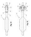
- FIG. 1is a partial cut away side view of first embodiment of a percutaneous transluminal angioplasty device according to a first embodiment of the disclosed invention, with the angioplasty balloon and embolism filter in their collapsed positions.
- FIG. 2is a partial cut away side view of the percutaneous transluminal angioplasty device of FIG. 1 showing the angioplasty balloon and embolism filter in their erected positions.
- FIG. 3is a cross sectional view taken along line 3 - 3 of FIG. 1 .
- FIG. 4is a cross sectional view taken along line 4 - 4 of FIG. 1 .
- FIG. 5is a cross sectional view taken along line 5 - 5 of FIG. 1 .
- FIG. 6is a second embodiment of a percutaneous transluminal angioplasty device according to the present invention, which differs from the percutaneous transluminal angioplasty of FIGS. 1 and 2 in that the actuation balloon is on the proximal side of the embolic filter, and the filter erects from a different direction.
- FIG. 7is a view of the percutaneous transluminal angioplasty device of FIG. 6 showing the angioplasty balloon inflated and the embolic filter erected.
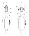
- FIG. 8is a third embodiment of a percutaneous transluminal angioplasty device and differs from the previously described embodiments in that the means for erecting the embolic filter is a bellows.
- FIG. 8shows the angioplasty balloon and the embolic filter in their collapsed positions.
- FIG. 9is another view of the percutaneous transluminal angioplasty device of FIG. 8 showing the angioplasty balloon and the embolic filter in their inflated or raised positions.
- FIG. 10is another embodiment of a percutaneous transluminal angioplasty device according to the present invention which employs a bellows to raise and lower the embolic filter.
- the embodiment of FIG. 10differs from the embodiment of FIGS. 8 and 9 in that the bellows is disposed on the distal end of the filter such that the filter opens from the opposite direction.
- FIG. 10shows the angioplasty balloon and the embolic filter in their deflated or collapsed positions.
- FIG. 11is another view of the percutaneous transluminal angioplasty device of FIG. 10 , showing the angioplasty balloon inflated and the embolic filter raised.
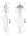
- FIG. 12shows still another embodiment of a percutaneous transluminal angioplasty device according to the present invention, in which the balloon interposed between the catheter shaft and the ribs forces the ribs upward, thereby causing them to bow into the erected embolic filter.
- FIG. 12shows the device with the angioplasty balloon and the embolic filter in their collapsed or lowered positions.
- FIG. 13is another view of the percutaneous transluminal angioplasty device of FIG. 12 , showing the angioplasty balloon in its inflated condition and the embolic filter in its erected condition.
- FIG. 14is another embodiment of a percutaneous transluminal angioplasty device according to the present invention. This embodiment differs from the embodiments of FIGS. 12 and 13 in that the balloon is located at the opposite end of the filter. Nonetheless, when inflated, the balloon forces the ribs away from the shaft and into their accurate positions, thereby raising the embolic filter.
- FIG. 14shows the embodiment with the angioplasty balloon collapsed and the embolic filter retracted against the catheter shaft.
- FIG. 15is another view of the embodiment of FIG. 14 , showing the angioplasty balloon inflated and the embolic filter erected.
- FIG. 16is still another embodiment of a percutaneous transluminal angioplasty device according to the present invention.
- This embodimentemploys a pull wire operable from outside the patient which is attached to a front ring of the embolic filter.
- the physicianexerts tension on the wire, the distal ring is displaced proximally, bringing it closer to the proximal ring, thereby causing the ribs to bow outward and thereby erecting the embolic mesh filter.
- FIG. 16shows the device with the angioplasty balloon deflated and the embolic filter collapsed against the catheter shaft.
- FIG. 17is a different view of the embodiment of FIG. 16 and shows the angioplasty balloon inflated and the embolic filter erected.
- FIG. 18is another embodiment of a percutaneous transluminal angioplasty device according to the present invention, showing the angioplasty balloon and the embolic filter in their collapsed conditions.
- FIG. 19is another view of the embodiment of FIG. 18 , showing the angioplasty balloon inflated and the embolic filter raised.
- FIG. 20is yet another embodiment of a percutaneous transluminal angioplasty device according to the present invention, showing the angioplasty balloon and the embolic filter in their collapsed conditions.
- FIG. 21is another view of the embodiment of FIG. 20 , showing the angioplasty balloon inflated and the embolic filter raised.
- FIG. 22shows a side cut away view of a coronary artery with a stenosis.
- FIG. 23shows the coronary artery of FIG. 20 with a guide wire fed through the coronary artery and through the stenosis.
- FIG. 24shows the device of FIG. 1 threaded over the guide wire of FIG. 23 and positioned such that the angioplasty balloon is located within the stenosis.
- FIG. 25illustrates the angioplasty balloon in its inflated condition to reduce the stenosis, and the embolic filter has been erected to capture any embolic particles that may break loose into the blood stream as a result of the angioplasty procedure.
- FIG. 26is a partial cut away side view of an embodiment of a device in which the angioplasty balloon and embolism filter, shown in their collapsed positions, are reversed on the catheter shaft for peripheral vascular applications in which blood flows in the opposite direction.
- FIG. 27is a partial cut away side view of the device of FIG. 26 showing the angioplasty balloon and embolism filter in their erected positions.
- FIG. 28is a side view of an embolism filter according to another embodiment of the present invention.
- FIG. 29is a side view of the embolism filter of FIG. 28 with the inflation balloon expanded to erect the embolism filter; filter mesh is shown removed to reveal interior detail.
- FIG. 30is a side view of the embolism filter of FIG. 28 with the inflation balloon deflated; filter mesh is shown removed to reveal interior detail.
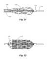
- FIG. 31is a side view of the embolism filter of FIG. 28 being retracted into the forward end of a catheter to collapse the filter; filter mesh is shown removed to reveal interior detail.
- FIG. 32is a side view of the embolism filter of FIG. 28 , with the filter expanded and filter mesh in place.
- FIG. 33is a side cutaway view of another embodiment of an angioplasty device showing an angioplasty balloon in its deflated condition and an embolic filter in a retracted state.
- FIG. 34is a side cutaway view of the angioplasty device of FIG. 33 showing the angioplasty balloon inflated and the embolic filter erected.
- FIG. 35is a side view of a further embodiment of an angioplasty device in which the filter mesh extends beyond the end of the ribs so as to form a sac when the filter is collapsed.
- FIG. 36is a side view of the embodiment of FIG. 35 showing the filter in a collapsed condition.
- FIG. 37is a projection of a generally cylindrical filter frame of a still further embodiment of a catheter with integral embolic filter, i.e., the generally cylindrical filter frame is shown unrolled and flattened.
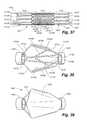
- FIG. 38is a perspective view of the filter frame of FIG. 37 showing the frame in an expanded condition.
- FIG. 39is a perspective view of the expanded filter frame of FIG. 38 showing a filter membrane installed over the frame.
- FIG. 40is a projection of a generally cylindrical filter frame of yet another embodiment of a catheter with integral embolic filter, i.e., the generally cylindrical filter frame is shown unrolled and flattened.
- FIG. 41is a projection of a generally cylindrical filter frame of still another embodiment of a catheter with integral embolic filter, i.e., the generally cylindrical filter frame is shown unrolled and flattened.
- FIG. 42is an end view of a filter membrane of a type suitable for use with the filter frames of FIGS. 37, 40, and 41 .
- FIG. 43is a side view of the filter membrane of FIG. 42 .
- FIG. 44is an isometric view of the filter membrane of FIG. 42 .
- FIGS. 1 and 2illustrate a first embodiment of a percutaneous transluminal angioplasty device 10 according to the present invention.
- the device 10comprises an elongated catheter 12 having a shaft 14 with a proximal end (not shown) and a distal end 16 . Spaced a short distance proximally from the distal end 16 of the catheter 12 is an angioplasty balloon 18 of conventional design.
- the angioplasty balloon 18is shown in a deflated or collapsed condition.
- FIG. 2the angioplasty balloon 18 is shown in an inflated condition.
- the filter 20includes a proximal ring portion 22 and a distal ring portion 24 .
- a plurality of elongated ribs 26extend generally longitudinally between the proximal and distal rings 22 , 24 . These ribs can be made of a shape memory material, such as nitinol, and in their baseline position, these ribs are collapsed.
- a filter mesh 28overlies the distal portion of the ribs 26 . In the embodiment of FIGS. 1 and 2 , the distal ring 24 is movable toward and away from the proximal ring 22 .
- FIG. 1shows the filter 20 in its collapsed condition
- FIG. 2shows the filter in its erected condition.
- Means 34are included for erecting and collapsing the filter 20 of the device 10 shown in FIGS. 1 and 2 .
- a balloon 36has its distal end 38 bonded to the shaft 14 of the catheter 12 .
- the distal ring 24is in its withdrawn position, as shown in FIG. 1 , the bulk of the balloon 36 is folded forward over the shaft 14 of the catheter 12 .
- the balloon 36is inflated, as shown in FIG. 2 , the balloon 36 expands proximally, pushing the distal ring 24 in a proximal direction, causing the ribs 26 to bow outward and thereby erecting the filter 20 .
- the shape memory ribsstraighten, urging the distal ring 24 in a distal direction and collapsing the filter 20 close to the shaft 14 of the catheter 12 .
- FIGS. 3, 4, and 5show cross sections of the device 10 at various locations along its length.
- the catheter shaft 12has three lumens: two smaller lumens and a large main lumen.
- the two smaller lumensare inflation lumens, one lumen 40 for the angioplasty balloon 18 , and one lumen 42 for the balloon 36 which controls the filter 20 .
- the larger main lumen 44is used to receive a guide wire (not shown) over which the device 10 is advanced to position the device for performing an angioplasty procedure.
- FIG. 4this cross section is taken at a location distal to the angioplasty balloon 18 . Consequently, the angioplasty balloon inflation lumen 40 has terminated and is no longer visible. Thus, FIG. 4 shows only two lumens, the main lumen 44 for receiving the guide wire, and the smaller inflation lumen 42 for the filter balloon 36 .
- this cross sectionis taken at a location distal to the filter balloon 36 , and hence only the main lumen 44 is visible.
- FIGS. 6 and 7show an alternate embodiment of a percutaneous transluminal angioplasty device 110 according to the present invention.
- This deviceis similar to the device 10 previously described, with the exception that the filter 120 , in this case, has its distal ring 124 fixed, and the proximal ring 122 of the filter 120 is movable toward and away from the distal ring to cause the ribs 126 to bow outwardly or to straighten.
- the balloon 136is located on the proximal side of the filter 120 and pushes the proximal ring 122 in a distal direction when the balloon 136 is inflated.
- FIGS. 8 and 9yet another alternate embodiment of a percutaneous transluminal angioplasty device 210 is shown.
- This deviceis similar to the device shown in FIGS. 1 and 2 , with the exception that the means for erecting the filter 220 is a bellows 236 , instead of a balloon.
- the bellows 236is uninflated and hence it is in a collapsed condition, permitting the ribs 226 of the filter 220 to straighten out against the shaft 214 of the catheter 212 .
- the bellows 236has been inflated, pushing the proximal ring 222 in a distal direction, bowing out the ribs 236 and erecting the filter mesh 238 .
- FIGS. 10 and 11illustrate still another embodiment of a percutaneous transluminal angioplasty device 310 .
- This deviceis similar to the device shown in FIGS. 8 and 9 , with the exception that the bellows 336 is placed on the distal side of the filter 320 .
- the bellows 336when the bellows 336 is inflated, it moves the distal ring 324 in a proximal direction toward the proximal ring 322 , thereby causing the ribs 326 to bow outwardly, erecting the filter mesh 338 .
- FIGS. 12 and 13depict another embodiment of a percutaneous transluminal angioplasty device 410 .
- the means for erecting the filtercomprises a balloon 436 disposed between the catheter shaft 414 and the ribs 426 adjacent the fixed distal ring 424 of the filter 420 .
- the balloon 436When the balloon 436 is inflated, it forces the ribs 426 outward away from the catheter shaft 414 , thereby bowing the ribs and drawing the proximal ring 422 of the filter 420 in a distal direction. As the ribs 426 bow outward, the filter mesh 428 is erected, thereby raising the filter 420 .
- FIGS. 14 and 15show a device 510 similar to that shown in FIGS. 12 and 13 , with the exception that the balloon 536 is placed between the catheter shaft 512 and the ribs 526 adjacent the proximal ring 522 of the filter 520 .
- the distal ring 524is free to slide along the catheter shaft 512 , such that when the balloon 536 is inflated and forces the ribs 526 to bow outward, the distal ring 524 slides in a proximal direction, as indicated by the arrow 539 as shown in FIG. 15 , permitting the filter 520 to raise.
- the embodiment 610 shown in FIGS. 16 and 17employs a different means for erecting the filter 620 .
- a pull wire 650is used.
- the pull wire 650extends through what would formerly have been used as the filter balloon inflation lumen 644 , and the distal end 652 of the pull wire 650 is attached to the distal ring 624 .
- the physicianwishes to raise the filter 620 , he exerts a tension on the wire 650 , as indicated by the arrow 653 , thus drawing the distal ring 624 in a proximal direction as indicated by the arrow 655 toward the proximal ring 622 .
- the ribsbow 626 outward, erecting the filter mesh 628 as shown in FIG. 17 .
- the distal end 752 of a push wire 750is attached to the proximal ring 722 .
- the proximal ring 722is advanced distally toward the distal ring 724 in the direction indicated by the arrow 755 , causing the ribs 726 to bow outward and thereby erecting the filter 720 , as shown in FIG. 19 .
- the device 810 shown in FIGS. 20 and 21uses a pull wire 850 to erect the filter 820 .
- the pull wire 850wraps around an opening 851 in the stationary distal ring 824 and extends rearward toward the proximal ring 822 to which the distal end 852 of the pull wire is attached.
- the proximal ring 822is drawn distally toward the distal ring 824 in the direction indicated by the arrow 855 , causing the ribs 826 to bow outward and thereby erecting the filter 820 , as shown in FIG. 21 .
- FIG. 22shows a vascular structure (e.g., coronary artery, saphenous vein graft, renal artery, carotid artery, superficial femoral artery, etc.) 900 with upper and lower walls 902 , 904 , a branch vessel 905 , and a stenosis or blockage 906 caused by the build up of plaque or other substances on the arterial walls in such a way as to narrow the diameter of the arterial lumen, and in the process, constrict the flow of blood therethrough.
- a vascular structuree.g., coronary artery, saphenous vein graft, renal artery, carotid artery, superficial femoral artery, etc.
- a guide wire 908has been inserted by the physician, such as through the femoral artery, and guided through the vascular system until the guide wire passes through the stenosis 906 in the vascular structure 900 .
- the apparatus 10has been inserted over the guide wire 908 and advanced to a location wherein the angioplasty balloon resides within the stenosis 906 .
- the embolic filter 20resides a few centimeters distal or downstream from the angioplasty location. In FIG. 24 both the angioplasty balloon and the embolic filter are shown in their collapsed conditions.
- FIG. 25the embolic filter 20 has been erected by inflating the filter balloon 36 , causing the distal ring 22 to slide in a proximal direction along the catheter shaft 12 .
- the mesh filter material 28 supported by the ribsspreads so as to cover substantially the entire arterial lumen.
- the angioplasty balloon 18is now inflated. As the balloon 18 inflates, it pushes tissue and plaque forming the stenosis 906 outward, opening the stenosis and possibly loosening embolic particles in the process. Any such embolic particles which get captured in the blood stream will be caught by the embolic filter 20 and will thereby be prevented from traveling to a location where they can cause clinical damage.
- the filter 20is erected relative to the stenosis 906 .
- the filter 20is erected to capture embolic particles upstream of the branch vessel.
- the preferred procedureis to deflate the angioplasty balloon 18 first, prior to collapsing the embolic filter 20 .
- any embolic particles that are broken loose as the angioplasty balloon 18 deflateswill be captured by the filter 20 .
- the embolic filter balloon 20is then deflated, permitting the ribs 26 and filter mesh 28 to collapse against the shaft 14 of the catheter 12 . Any embolic particles captured by the mesh 28 are trapped against the shaft 14 .
- the device 10is then withdrawn over the guide wire 908 and removed from the patient's body.
- FIGS. 26 and 27illustrate a device 1000 in which the angioplasty balloon 1018 and the embolic filter 1020 are reversed on the shaft 1014 of the catheter 1012 .
- the embolic filter 1020will be proximal to the angioplasty balloon 1018 and thus positioned to capture any embolic particles that may be dislodged by the angioplasty balloon.
- FIGS. 26 and 27employs the same method and device for erecting the embolic filter as the embodiment 10 of FIGS. 1-3 , it will be understood that the methods and devices for erecting the embolic filter of other embodiments disclosed above are equally applicable to a configuration like the device of embodiment 1000 where the angioplasty balloon is positioned between the embolic filter and the tip of the device.
- FIGS. 28-32show still another embodiment of an embolic filter 1120 for use in conjunction with an angioplasty balloon.
- FIGS. 28-32show only the embolic filter 1120 and not the angioplasty balloon, but it will be understood that the embolic filter is located on the same catheter 1114 as the angioplasty balloon in the same manner as the embodiments previously disclosed.
- FIGS. 29-31show the embolic filter 1120 without its filter mesh 1128 for clarity of illustration.
- the embolic filter 1120is folded closely against the shaft 1114 of the catheter 1112 .
- the ribs 1126 of the filter 1120extend between a proximal ring portion 1122 and a distal ring portion 1124 .
- the distal ring portion 1124is slidably mounted on the shaft 1114 of the catheter 1112 , and the proximal ring portion 1122 is fixed with relation to the shaft of the catheter.
- the embolic filter balloon 1136has been inflated, expanding the ribs 1126 of the embolic filter. As the ribs expand, the distal ring portion 1124 slides in the proximal direction, as shown by the arrow 1188 . Once expanded, the ribs 1126 maintain their shape, such that when the embolic filter balloon 1136 is deflated, as shown in FIG. 30 , the embolic filter 1120 remains expanded.
- a second, outer catheter 1190is advanced over the catheter 1112 , as shown in FIG. 31 , causing the ribs 1126 to collapse as the embolic filter is withdrawn into the forward end of the outer catheter 1190 .
- the distal ring portion 1124slides in the distal direction.
- FIG. 32shows the embolic filter 1120 with filter mesh 1128 positioned over the ribs 1126 .
- FIGS. 33 and 34illustrate a further embodiment of a percutaneous angioplasty device 1210 , in which the embolic filter 1220 is located on a different carrier than the angioplasty balloon 1218 .
- the angioplasty balloon 1218is located on an outer catheter 1294
- the embolic filter 1220is located at the forward end of an inner catheter 1295 .
- the outer catheterpreferably has three lumens, one for inflating the angioplasty balloon 1218 , one for accommodating a guide wire (not shown), and one for receiving the inner catheter 1295 and embolic filter 1220 .
- the inner catheter 1295is slidably telescopically disposed within the outer catheter 1294 .
- the ribs 1226 of the embolic filter 1220are formed from a shape-memory metal such as nitinol and are constructed to normally assume an “open” configuration. When retracted within the forward end of the outer catheter 1294 , the ribs 1226 of the embolic filter collapse.
- the inner catheteris inserted into the outer catheter so that the embolic filter 1220 is collapsed within the distal end of the device, as shown in FIG. 33 .
- the outer and inner catheters 1294 , 1295are inserted together, such as through the femoral artery, over a guidewire and advanced through the vascular system to a location wherein the uninflated angioplasty balloon 1218 resides within the stenosis. Once location of the angioplasty balloon 1218 within the stenosis has been verified by suitable medical imaging technology, the inner catheter is advanced to progress the embolic filter 1220 beyond the forward end of the outer catheter 1294 .
- the ribsassume their expanded configuration and erect the embolic filter. Thereafter the angioplasty balloon 1218 may be inflated to treat the stenosis, and any emboli loosened during the procedure will be captured by the embolic filter 1220 downstream of the stenosis.
- the angioplasty balloon 1218is deflated, and the embolic filter 1220 is withdrawn back into the forward end of the outer catheter 1294 .
- the outer and inner catheters 1294 , 1295are then withdrawn together from the patient.
- a wirecan be substituted for the inner catheter 1295 as a means for carrying the embolic filter 1220 .
- FIGS. 35 and 36show an angioplasty device 1310 that is identical to the device 10 , with the exception that the filter mesh 1328 extends distally beyond the end of the ribs 1326 and is attached to the distal end of the distal ring 1324 .
- a sac 1398is formed which helps contain the embolic particles, thereby minimizing the possibility that the ribs 1326 will squeeze the particles out of the filter.
- FIGS. 37-39an alternate embodiment of a filter 1400 is shown.
- the filter 1400has a generally tubular shape with a proximal ring 1404 at one end, a distal ring 1406 at the other, and a filter frame 1402 connecting the two rings.
- FIG. 37is a projection of a cylinder, i.e. a generally cylindrical filter 1400 is shown unrolled and flattened.
- the frame 1402is made of flexible material such as Nitinol.
- the frame 1402comprises a first plurality of longitudinal struts 1412 extending inward from one end ring 1404 .
- a second plurality of longitudinal struts 1413extends inward from the opposite end ring 1406 .
- the second struts 1413are circumferentially offset from the first struts 1412 .
- a connecting plurality of intermediate struts 1414link the adjacent ends of the longitudinal struts 1412 , 1413 .
- the number of first longitudinal struts 1412is equal to the number of second longitudinal struts 1413 , and there are twice as many intermediate connecting struts 1414 as there are struts 1412 or struts 1413 .
- first strut 1412 Ais connected to the ends of second struts 1413 A and 1413 B by intermediate struts 1414 A and 1414 B.
- the end of first strut 1412 Bis connected to the ends of second struts 1413 B and 1413 C by intermediate struts 1414 C and 1414 D.
- the end of first strut 1412 Cis connected to the ends of second struts 1413 C and 1413 D by intermediate struts 1414 E and 1414 F.
- the end of first strut 1412 Dis connected to the ends of second struts 1413 D and 1413 A by intermediate struts 1414 G and 1414 H.
- FIG. 37is a projection of a cylinder, i.e. a generally cylindrical filter unrolled and flattened, half of second strut 1413 A is shown at the top of the projection, and the other half of second strut 1413 A is shown at the bottom of the projection.
- intermediate struts 1414form a serpentine-like pattern.
- a first end of intermediate strut 1414 Ais connected to a first end of intermediate strut 1414 B by a loop portion.
- a second end of intermediate strut 1414 Bis connected to a second end of intermediate strut 1414 C by another loop portion, and so on.
- the longitudinal struts 1412 , 1413are connected to the intermediate struts 1414 at the loop portions.
- Points of weakness 1420are formed on the support frame 1402 in strategic locations to facilitate controlled bending of the frame 1402 .
- these points of weaknesscomprise points of reduced cross-sectional area.
- these points of weaknessare formed at the connection points between the rings 1404 , 1406 and the longitudinal struts 1412 , 1413 and at the connection between the longitudinal struts 1412 , 1413 and intermediate struts 1414 . Because of the narrow width at the connection points the longitudinal struts 1412 , 1413 can flare open in the radial direction, while simultaneously expanding causing the intermediate struts 1414 to expand radially.
- the filter frame 1402assumes an expanded configuration as shown in FIG. 38 .
- the longitudinal struts 1412 A-D and 1413 A-Dpivot radially outward, while the intermediate struts 1414 A-H spread apart to permit circumferential expansion of the support frame 1402 .
- first longitudinal strut 1412 Ais connected by intermediate struts 1414 A, H to two second longitudinal struts 1413 A, 1413 B.
- First longitudinal strut 1412 Bis connected by intermediate struts 1414 C, D to two second longitudinal struts 1413 B, 1413 C.
- First longitudinal strut 1412 Cis connected by intermediate struts 1414 E, F to two second longitudinal struts 1413 C, 1413 D.
- first longitudinal strut 1412 Dis connected by intermediate struts 1414 G, H to two second longitudinal struts 1413 D, 1413 A.
- each of the first longitudinal struts 1412 A-Dis connected to the ends of two corresponding second longitudinal struts 1413 A-D by intermediate struts 1414 A-H.
- FIG. 37shows that the strut 1413 B lies between intermediate struts 1414 B and 1414 C.
- intermediate struts 1414 B and 1414 Cboth lie between struts 1412 A and 1412 B.
- Strut 1413 Bthus lies between struts 1412 A and 1412 B such that the strut 1413 B is circumferentially offset with respect to both struts 1412 A and 1412 B.
- FIG. 39shows the filter frame 1402 covered in a filter membrane 1430 .
- the distal end of the filter membraneis open to permit embolic particles to enter the filter, where they are trapped by the filter membrane.
- FIGS. 40 and 41are cylindrical projections depicting alternate frame designs.
- the frame 1500comprises two sets of intermediate struts 1502 , 1053 that form serpentine patterns, and two sets of longitudinal frame members 1506 , 1507 interconnecting the intermediate struts and the rings 1508 , 1509 .
- the two sets of intermediate struts 1502 , 1503are joined by connecting members 1504 .
- Points of weaknessare formed at strategic locations, e.g. at connections between longitudinal struts 1506 , 1507 and intermediate struts 1502 , 1503 and at the connections between the intermediate struts 1502 , 1503 and the connecting members 1504 .
- FIG. 41depicts another embodiment of a frame 1600 in which the points of weakness are formed by circular or oval cutouts 1602 transverse to the longitudinal axis of the struts 1604 .
- These type of structures 1602provide flexibility resulting in easier opening and closing of the frame 1600 .
- These structures 1604also reduce the stress induced permanent set and hence, allow the frame 1600 to retract back to its original shape.
- the oval and/or circular structures 1602also provide enough longitudinal rigidity which will force the filter frame to open.
- FIGS. 42-44illustrate an embodiment of a filter membrane 1700 .
- the filter membrane 1700is in the shape of a funnel.
- the conical surface 1702 of the funnelhas a plurality of holes 1704 formed therein.
- the filter membrane 1700is comprised of semi-compliant material such as nylon or PebaxT or could be made up of elastic materials such as thermoplastic elastomers or thermoset elastomers. Some examples of thermoset elastomers polyurethane and copolymers (PellathaneTM T EcothaneTM, ChronoflesTM, etc). These materials allow placement of the holes 1704 close to each other. In the disclosed embodiment, the size of the holes 1704 is 40 microns, and the holes 1704 are placed 40 microns apart.
- the filter membrane 1700is attached to a support frame, such as the frames 1400 , 1500 , or 1600 hereinabove described, such that it covers one end of the frame as well as the centrally located serpentine strut structure. The other set of longitudinal struts remain exposed.
- the filter membrane 1700may be attached on the outside of the frame or on the inside of the frame.
- the proximal end of the membranecan be terminated at the proximal ring or can extend beyond the ring to attach to the shaft of the catheter.
- the filters herein depictedare deployed by pulling or pushing an actuation wire or inflating an actuation balloon, depending on the type of catheter chassis being used. As the filter is erected the serpentine struts expand circumferentially. The filter membrane is then deployed. Upon removal of the actuation force the filter retracts to its normally closed position.
- the filter materialis that its natural shape is in a closed or collapsed condition.
- the filter materialstretches as the filter is erected and collapses to its normal condition when the frame is retracted. Therefore, the membrane has no permanent set during storage and can always be expanded to a correct size. Further, because the filter collapses under the resiliency of the filter material, the filter does not require a recovery sheath. If needed, however, a sheath may be used to further collapse the filter with embolic debris prior to retrieval
- the filters of the disclosed embodimentare characterized by a long filter body that opposes the vessel wall over a greater area, thus reducing the chance of leakage between the filter and the vessel wall.
- an angioplasty balloonis but one means for relieving a stenosis in a vessel.
- Stents, mechanical thrombectomy devices, or other suitable apparatusmay be substituted for the angioplasty balloon and positioned on the catheter at a location proximal to the embolic filter.
- any emboli loosened by the stent or mechanical thrombectomy devicewill be captured by the embolic filter in the same manner as described above with respect to the angioplasty balloon.
- filter ribs of a shape memory metalsuch as nitinol
- a shape memory metalsuch as nitinol
- the ribswould be formed straight, forced open by the balloon, and return to their normal shape as a result of the resiliency of the structure. Or, in the case of the embodiment of FIGS. 33 and 34 , the ribs would be initially formed in an open position, deformed inwardly to fit within the outer catheter, and return to their normal open position when released from the confines of the outer catheter.
- the present inventionpermits the placement of the embolic filter very close to the means for treating the stenosis. This has the effect of minimizing the “landing area” of the filter and also permits the protection of side branches, as shown in FIGS. 22-25 .
Landscapes
- Health & Medical Sciences (AREA)
- Life Sciences & Earth Sciences (AREA)
- Heart & Thoracic Surgery (AREA)
- Engineering & Computer Science (AREA)
- General Health & Medical Sciences (AREA)
- Biomedical Technology (AREA)
- Veterinary Medicine (AREA)
- Vascular Medicine (AREA)
- Public Health (AREA)
- Animal Behavior & Ethology (AREA)
- Transplantation (AREA)
- Cardiology (AREA)
- Oral & Maxillofacial Surgery (AREA)
- Child & Adolescent Psychology (AREA)
- Biophysics (AREA)
- Pulmonology (AREA)
- Anesthesiology (AREA)
- Hematology (AREA)
- Surgical Instruments (AREA)
Abstract
Description
Claims (19)
Priority Applications (4)
| Application Number | Priority Date | Filing Date | Title |
|---|---|---|---|
| US11/763,118US9707071B2 (en) | 2004-11-24 | 2007-06-14 | Percutaneous transluminal angioplasty device with integral embolic filter |
| US13/838,523US20170007390A9 (en) | 2004-11-24 | 2013-03-15 | Percutaneous transluminal angioplasty device with integral embolic filter |
| US15/136,060US20160287844A1 (en) | 2004-11-24 | 2016-04-22 | Percutaneous transluminal angioplasty device with integral embolic filter |
| US15/651,429US10702367B2 (en) | 2004-11-24 | 2017-07-17 | Percutaneous transluminal angioplasty device with integral embolic filter |
Applications Claiming Priority (3)
| Application Number | Priority Date | Filing Date | Title |
|---|---|---|---|
| US10/997,803US8403976B2 (en) | 2004-04-08 | 2004-11-24 | Percutaneous transluminal angioplasty device with integral embolic filter |
| US81339506P | 2006-06-14 | 2006-06-14 | |
| US11/763,118US9707071B2 (en) | 2004-11-24 | 2007-06-14 | Percutaneous transluminal angioplasty device with integral embolic filter |
Related Parent Applications (1)
| Application Number | Title | Priority Date | Filing Date |
|---|---|---|---|
| US10/997,803Continuation-In-PartUS8403976B2 (en) | 2004-04-08 | 2004-11-24 | Percutaneous transluminal angioplasty device with integral embolic filter |
Related Child Applications (2)
| Application Number | Title | Priority Date | Filing Date |
|---|---|---|---|
| US13/838,523Continuation-In-PartUS20170007390A9 (en) | 2004-11-24 | 2013-03-15 | Percutaneous transluminal angioplasty device with integral embolic filter |
| US15/651,429ContinuationUS10702367B2 (en) | 2004-11-24 | 2017-07-17 | Percutaneous transluminal angioplasty device with integral embolic filter |
Publications (2)
| Publication Number | Publication Date |
|---|---|
| US20070299466A1 US20070299466A1 (en) | 2007-12-27 |
| US9707071B2true US9707071B2 (en) | 2017-07-18 |
Family
ID=38874442
Family Applications (2)
| Application Number | Title | Priority Date | Filing Date |
|---|---|---|---|
| US11/763,118Expired - Fee RelatedUS9707071B2 (en) | 2004-11-24 | 2007-06-14 | Percutaneous transluminal angioplasty device with integral embolic filter |
| US15/651,429Expired - LifetimeUS10702367B2 (en) | 2004-11-24 | 2017-07-17 | Percutaneous transluminal angioplasty device with integral embolic filter |
Family Applications After (1)
| Application Number | Title | Priority Date | Filing Date |
|---|---|---|---|
| US15/651,429Expired - LifetimeUS10702367B2 (en) | 2004-11-24 | 2017-07-17 | Percutaneous transluminal angioplasty device with integral embolic filter |
Country Status (1)
| Country | Link |
|---|---|
| US (2) | US9707071B2 (en) |
Cited By (5)
| Publication number | Priority date | Publication date | Assignee | Title |
|---|---|---|---|---|
| US11382643B2 (en) | 2017-10-16 | 2022-07-12 | Retriever Medical, Inc. | Clot removal methods and devices with multiple independently controllable elements |
| US11589881B2 (en) | 2017-10-16 | 2023-02-28 | Retriever Medical, Inc. | Clot removal methods and devices with multiple independently controllable elements |
| US11633202B1 (en) | 2017-10-16 | 2023-04-25 | Retriever Medical, Inc. | Catheter based retrieval device with proximal body having axial freedom of movement |
| US11877751B2 (en) | 2019-08-29 | 2024-01-23 | Emory University | Methods and devices configured to prevent aspiration |
| US12414785B1 (en) | 2025-03-17 | 2025-09-16 | Avantec Vascular Corporation | Cutters with pulsating vacuum control |
Families Citing this family (23)
| Publication number | Priority date | Publication date | Assignee | Title |
|---|---|---|---|---|
| US8403976B2 (en)* | 2004-04-08 | 2013-03-26 | Contego Medical Llc | Percutaneous transluminal angioplasty device with integral embolic filter |
| US9707071B2 (en) | 2004-11-24 | 2017-07-18 | Contego Medical Llc | Percutaneous transluminal angioplasty device with integral embolic filter |
| US9510930B2 (en)* | 2008-10-22 | 2016-12-06 | Contego Medical, Llc | Angioplasty device with embolic filter |
| US20080097399A1 (en)* | 2006-06-15 | 2008-04-24 | Ravish Sachar | Catheter With Adjustable Stiffness |
| WO2009151761A1 (en)* | 2008-04-10 | 2009-12-17 | Contego Medical Llc | Angioplasty device with embolic filter and fixed filter housing |
| US20100262219A1 (en)* | 2009-04-14 | 2010-10-14 | Frimerman Aharon | Device for angioplasty with an embolization protection component and method therefor |
| US8956385B2 (en) | 2009-04-14 | 2015-02-17 | Aharon FRIMERMAN | Integrated distal embolization protection apparatus for endo-luminal devices such as balloon, stent or tavi apparatus |
| WO2011144240A1 (en)* | 2010-05-20 | 2011-11-24 | Joline Gmbh & Co. Kg | Embolic protection catheter |
| US8641777B2 (en) | 2011-06-03 | 2014-02-04 | Reverse Medical Corporation | Embolic implant and method of use |
| US9211178B2 (en) | 2013-02-26 | 2015-12-15 | Medtronic, Inc. | Embolic protection device |
| US9211179B2 (en) | 2013-02-26 | 2015-12-15 | Medtronic, Inc. | Embolic protection device |
| JP2016511086A (en)* | 2013-03-15 | 2016-04-14 | コンテゴ・メディカル・リミテッド・ライアビリティ・カンパニーContego Medical, Llc | Percutaneous angioplasty device with integrated embolic filter |
| AU2016209053B2 (en) | 2015-01-23 | 2020-04-16 | Contego Medical, Inc. | Interventional device having an integrated embolic filter and associated methods |
| US10682145B2 (en)* | 2015-02-10 | 2020-06-16 | Boston Scientific Scimed, Inc. | Vascular occlusion devices |
| US11197750B2 (en) | 2016-11-29 | 2021-12-14 | Lake Region Manufacturing, Inc. | Embolic protection device |
| US11229451B2 (en) | 2017-12-13 | 2022-01-25 | Eric Raul GUERRA | Thrombectomy catheter and methods of use |
| US11134967B2 (en) | 2017-12-13 | 2021-10-05 | Eric Raul GUERRA | Thrombectomy catheter and methods of use |
| US11191556B2 (en) | 2018-03-01 | 2021-12-07 | Covidien Lp | Catheter including an expandable member |
| US11058848B2 (en) | 2019-05-02 | 2021-07-13 | Covidien Lp | Catheter including expandable member |
| EP4065041B1 (en)* | 2020-01-17 | 2025-07-30 | Edwards Lifesciences Corporation | Filter for deployment system |
| JP2024518961A (en) | 2021-06-07 | 2024-05-08 | アバンテック バスキュラー コーポレイション | Hybrid Atherectomy Device |
| WO2023147460A1 (en) | 2022-01-27 | 2023-08-03 | Contego Medical, Inc. | Thrombectomy and aspiration system and methods of use |
| US12220140B1 (en) | 2023-08-16 | 2025-02-11 | Avantec Vascular Corporation | Thrombectomy devices with lateral and vertical bias |
Citations (120)
| Publication number | Priority date | Publication date | Assignee | Title |
|---|---|---|---|---|
| US4723549A (en) | 1986-09-18 | 1988-02-09 | Wholey Mark H | Method and apparatus for dilating blood vessels |
| US5053008A (en) | 1990-11-21 | 1991-10-01 | Sandeep Bajaj | Intracardiac catheter |
| US5108419A (en) | 1990-08-16 | 1992-04-28 | Evi Corporation | Endovascular filter and method for use thereof |
| US5456667A (en) | 1993-05-20 | 1995-10-10 | Advanced Cardiovascular Systems, Inc. | Temporary stenting catheter with one-piece expandable segment |
| US5913895A (en) | 1997-06-02 | 1999-06-22 | Isostent, Inc. | Intravascular stent with enhanced rigidity strut members |
| US5954745A (en) | 1997-05-16 | 1999-09-21 | Gertler; Jonathan | Catheter-filter set having a compliant seal |
| US6001118A (en) | 1997-03-06 | 1999-12-14 | Scimed Life Systems, Inc. | Distal protection device and method |
| US6042598A (en) | 1997-05-08 | 2000-03-28 | Embol-X Inc. | Method of protecting a patient from embolization during cardiac surgery |
| US6051014A (en) | 1998-10-13 | 2000-04-18 | Embol-X, Inc. | Percutaneous filtration catheter for valve repair surgery and methods of use |
| US6168579B1 (en) | 1999-08-04 | 2001-01-02 | Scimed Life Systems, Inc. | Filter flush system and methods of use |
| US6179859B1 (en) | 1999-07-16 | 2001-01-30 | Baff Llc | Emboli filtration system and methods of use |
| US20010012951A1 (en) | 1999-07-16 | 2001-08-09 | Bates Mark C. | Emboli filtration system having integral strut arrangement and methods of use |
| US6325815B1 (en) | 1999-09-21 | 2001-12-04 | Microvena Corporation | Temporary vascular filter |
| US6344049B1 (en) | 1999-08-17 | 2002-02-05 | Scion Cardio-Vascular, Inc. | Filter for embolic material mounted on expandable frame and associated deployment system |
| US6355051B1 (en) | 1999-03-04 | 2002-03-12 | Bioguide Consulting, Inc. | Guidewire filter device |
| US6371970B1 (en) | 1999-07-30 | 2002-04-16 | Incept Llc | Vascular filter having articulation region and methods of use in the ascending aorta |
| US6391044B1 (en) | 1997-02-03 | 2002-05-21 | Angioguard, Inc. | Vascular filter system |
| US20020156457A1 (en) | 1999-10-25 | 2002-10-24 | Fisher John S. | Emboli capturing device |
| US6485502B2 (en) | 2000-03-10 | 2002-11-26 | T. Anthony Don Michael | Vascular embolism prevention device employing filters |
| JP2002336261A (en) | 2001-04-03 | 2002-11-26 | Medtronic Ave Inc | Temporary luminal filter guide wire and its usage |
| US20030004536A1 (en) | 2001-06-29 | 2003-01-02 | Boylan John F. | Variable thickness embolic filtering devices and method of manufacturing the same |
| US6511503B1 (en) | 1999-12-30 | 2003-01-28 | Advanced Cardiovascular Systems, Inc. | Catheter apparatus for treating occluded vessels and filtering embolic debris and method of use |
| US6511496B1 (en) | 2000-09-12 | 2003-01-28 | Advanced Cardiovascular Systems, Inc. | Embolic protection device for use in interventional procedures |
| US6524303B1 (en) | 2000-09-08 | 2003-02-25 | Stereotaxis, Inc. | Variable stiffness magnetic catheter |
| US20030055480A1 (en) | 2001-09-14 | 2003-03-20 | Fischell David R. | Recannalization device with integrated distal emboli protection |
| US20030060843A1 (en) | 2001-09-27 | 2003-03-27 | Don Boucher | Vascular filter system with encapsulated filter |
| US6540722B1 (en)* | 1999-12-30 | 2003-04-01 | Advanced Cardiovascular Systems, Inc. | Embolic protection devices |
| US20030065354A1 (en)* | 2001-09-28 | 2003-04-03 | Boyle William J. | Embolic filtering devices |
| US20030083736A1 (en) | 1995-03-01 | 2003-05-01 | Brian J. Brown | Longitudinally flexible expandable stent |
| US20030093106A1 (en) | 2001-06-27 | 2003-05-15 | Eamon Brady | Catheter |
| US6592606B2 (en) | 2001-08-31 | 2003-07-15 | Advanced Cardiovascular Systems, Inc. | Hinged short cage for an embolic protection device |
| US6596011B2 (en) | 2001-06-12 | 2003-07-22 | Cordis Corporation | Emboli extraction catheter and vascular filter system |
| US20030139764A1 (en)* | 1999-04-01 | 2003-07-24 | Levinson Melvin E. | Radiopaque locking frame, filter and flexible end |
| US6607506B2 (en) | 2000-02-01 | 2003-08-19 | Harold D. Kletschka | Embolic protection device having an expandable trap |
| US20030167084A1 (en) | 1999-05-19 | 2003-09-04 | Michael Orlowski | Radially expandable vascular stent |
| US20030176884A1 (en) | 2002-03-12 | 2003-09-18 | Marwane Berrada | Everted filter device |
| US6635084B2 (en) | 1994-03-17 | 2003-10-21 | Medinol, Ltd. | Flexible expandable stent |
| US6638294B1 (en) | 2001-08-30 | 2003-10-28 | Advanced Cardiovascular Systems, Inc. | Self furling umbrella frame for carotid filter |
| US20030216792A1 (en) | 2002-04-08 | 2003-11-20 | Levin Howard R. | Renal nerve stimulation method and apparatus for treatment of patients |
| US6652557B1 (en) | 2001-08-29 | 2003-11-25 | Macdonald Kenneth A. | Mechanism for capturing debris generated during vascular procedures |
| US20030220665A1 (en) | 2002-05-23 | 2003-11-27 | Alan Eskuri | Cartridge embolic protection filter and methods of use |
| US6656351B2 (en) | 2001-08-31 | 2003-12-02 | Advanced Cardiovascular Systems, Inc. | Embolic protection devices one way porous membrane |
| US6656203B2 (en) | 2001-07-18 | 2003-12-02 | Cordis Corporation | Integral vascular filter system |
| US20030225435A1 (en)* | 2001-06-29 | 2003-12-04 | Huter Benjamin C. | Filter device for embolic protection systems |
| US6663650B2 (en) | 2000-06-29 | 2003-12-16 | Concentric Medical, Inc. | Systems, methods and devices for removing obstructions from a blood vessel |
| US6682543B2 (en) | 1996-07-17 | 2004-01-27 | C Edwards Lifesciences Corporation | Methods for aortic artherectomy |
| US6702834B1 (en) | 1999-12-30 | 2004-03-09 | Advanced Cardiovascular Systems, Inc. | Embolic protection devices |
| US20040054322A1 (en) | 2002-09-12 | 2004-03-18 | Vargas Jaime Salvador | Shape-transferring cannula system and method of use |
| US20040122466A1 (en) | 2002-12-23 | 2004-06-24 | Syntheon, Llc | Emboli and thrombi filter device and method of using the same |
| US20040158280A1 (en) | 2003-01-17 | 2004-08-12 | Scion Cardio-Vascular, Inc. | Proximal actuator for medical device |
| US20040167564A1 (en) | 2003-02-24 | 2004-08-26 | Scimed Life Systems, Inc. | Multi-wire embolic protection filtering device |
| US20040172128A1 (en) | 2001-06-27 | 2004-09-02 | James Hong | Stent pattern with figure-eights |
| WO2004096089A2 (en) | 2003-04-29 | 2004-11-11 | Rex Medical, L.P. | Distal protection device |
| US20040260387A1 (en) | 2003-05-23 | 2004-12-23 | Regala Alan Chung | Drug-injecting stent for sustained and distributed drug delivery |
| US20050015111A1 (en) | 2001-06-18 | 2005-01-20 | Mcguckin James F. | Vein filter |
| WO2005004968A1 (en) | 2003-07-02 | 2005-01-20 | Medtronic Vascular Inc. | Devices and methods for aspirating from filters |
| US20050038468A1 (en)* | 2003-07-03 | 2005-02-17 | Regents Of The University Of Minnesota | Medical device and method of intravenous filtration |
| US20050119668A1 (en) | 2003-09-18 | 2005-06-02 | Boston Scientific Scimed, Inc. | Medical retrieval devices and methods |
| US6939373B2 (en) | 2003-08-20 | 2005-09-06 | Advanced Cardiovascular Systems, Inc. | Intravascular stent |
| US20050228438A1 (en) | 2004-04-08 | 2005-10-13 | Ravish Sachar | Percutaneous transluminal angioplasty device with integral embolic filter |
| US6964673B2 (en) | 1997-05-08 | 2005-11-15 | Scimed Life Systems, Inc. | Percutaneous catheter and guidewire having filter and medical device deployment capabilities |
| US6969396B2 (en) | 2003-05-07 | 2005-11-29 | Scimed Life Systems, Inc. | Filter membrane with increased surface area |
| US6978174B2 (en) | 2002-04-08 | 2005-12-20 | Ardian, Inc. | Methods and devices for renal nerve blocking |
| US20050288730A1 (en) | 2002-04-08 | 2005-12-29 | Mark Deem | Methods and apparatus for renal neuromodulation |
| US20060015139A1 (en) | 1999-11-15 | 2006-01-19 | Ross Tsugita | Guidewire filter and methods of use |
| US6991641B2 (en) | 1999-02-12 | 2006-01-31 | Cordis Corporation | Low profile vascular filter system |
| US6994718B2 (en) | 2003-10-29 | 2006-02-07 | Medtronic Vascular, Inc. | Distal protection device for filtering and occlusion |
| US20060041277A1 (en) | 2002-04-08 | 2006-02-23 | Mark Deem | Methods and apparatus for renal neuromodulation |
| US20060100658A1 (en) | 2004-11-09 | 2006-05-11 | Hiroyuki Obana | Interventional guiding sheath system and method of use |
| US7044958B2 (en) | 2001-04-03 | 2006-05-16 | Medtronic Vascular, Inc. | Temporary device for capturing embolic material |
| US20060129130A1 (en) | 2004-11-18 | 2006-06-15 | Tal Michael G | Sheath/catheter system with controlled hardness and flexibility |
| US20060142801A1 (en) | 2002-04-08 | 2006-06-29 | Ardian, Inc. | Methods and apparatus for intravascularly-induced neuromodulation |
| US7083633B2 (en) | 2002-09-03 | 2006-08-01 | Advanced Vascular Technologies Llc | Arterial embolic filter deployed from catheter |
| US7094249B1 (en) | 1997-03-06 | 2006-08-22 | Boston Scientific Scimed, Inc. | Distal protection device and method |
| US7097651B2 (en) | 2001-09-06 | 2006-08-29 | Advanced Cardiovascular Systems, Inc. | Embolic protection basket |
| US20060235474A1 (en) | 2002-04-08 | 2006-10-19 | Ardian, Inc. | Methods and apparatus for multi-vessel renal neuromodulation |
| US7163549B2 (en) | 2003-02-11 | 2007-01-16 | Boston Scientific Scimed Inc. | Filter membrane manufacturing method |
| US20070043306A1 (en) | 2005-07-27 | 2007-02-22 | Greg Olson | Medical devices with variable stiffness |
| US20070061418A1 (en) | 2000-12-21 | 2007-03-15 | Berg Mitchell T | Method and system for initiating execution of software in response to a state |
| US7241305B2 (en) | 1997-06-02 | 2007-07-10 | Medtronic Vascular, Inc. | Apparatus for trapping emboli |
| US20070167975A1 (en) | 1999-12-30 | 2007-07-19 | Boyle William J | Embolic protection devices |
| US20070299466A1 (en) | 2004-11-24 | 2007-12-27 | Ravish Sachar | Percutaneous Transluminal Angioplasty Device With Integral Embolic Filter |
| US20080097399A1 (en) | 2006-06-15 | 2008-04-24 | Ravish Sachar | Catheter With Adjustable Stiffness |
| JP2008542291A (en) | 2005-05-26 | 2008-11-27 | ニューロン システムズ | Compositions and methods for treating retinal diseases |
| US7481823B2 (en) | 2002-10-25 | 2009-01-27 | Boston Scientific Scimed, Inc. | Multiple membrane embolic protection filter |
| WO2009151761A1 (en) | 2008-04-10 | 2009-12-17 | Contego Medical Llc | Angioplasty device with embolic filter and fixed filter housing |
| US20100010534A1 (en) | 2008-07-14 | 2010-01-14 | Boston Scientific Scimed, Inc. | Embolic protection device |
| US20100106182A1 (en) | 2008-10-22 | 2010-04-29 | Patel Udayan G | Angioplasty device with embolic filter |
| US7780696B2 (en)* | 1997-03-06 | 2010-08-24 | Boston Scientific Scimed, Inc. | Distal protection device and method |
| US20110004291A1 (en) | 2009-07-02 | 2011-01-06 | Tryton Medical, Inc. | Ostium support for treating vascular bifurcations |
| US20110071619A1 (en) | 2009-09-18 | 2011-03-24 | Medtronic Vascular, Inc. | Stent With Constant Stiffness Along the Length of the Stent |
| US7935075B2 (en) | 2005-04-26 | 2011-05-03 | Cardiac Pacemakers, Inc. | Self-deploying vascular occlusion device |
| US20110137399A1 (en) | 2009-12-02 | 2011-06-09 | Chomas James E | Microvalve Protection Device and Method of Use for Protection Against Embolization Agent Reflux |
| US8150520B2 (en) | 2002-04-08 | 2012-04-03 | Ardian, Inc. | Methods for catheter-based renal denervation |
| US8303617B2 (en) | 2002-05-13 | 2012-11-06 | Salviac Limited | Embolic protection system |
| US20120330402A1 (en) | 2011-06-24 | 2012-12-27 | Cook Medical Technologies Llc | Helical stent |
| US20130031087A1 (en) | 2011-07-28 | 2013-01-31 | Kikin Inc. | Systems and methods for contextual personalized searching |
| US8372108B2 (en) | 2009-01-16 | 2013-02-12 | Claret Medical, Inc. | Intravascular blood filter |
| JP2013049398A (en) | 2011-08-31 | 2013-03-14 | Piolax Inc | Check valve |
| US8409240B2 (en) | 2009-11-25 | 2013-04-02 | Boston Scientific Scimed, Inc. | Embolic protection device |
| JP2013154183A (en) | 2013-03-12 | 2013-08-15 | Contego Medical Llc | Percutaneous intravascular blood vessel formation device having integrated embolic filter |
| US8518073B2 (en) | 2009-01-29 | 2013-08-27 | Claret Medical, Inc. | Illuminated intravascular blood filter |
| US20130310871A1 (en) | 2004-11-24 | 2013-11-21 | Contego Medical, Llc | Percutaneous transluminal angioplasty device with integral embolic filter |
| US8603131B2 (en) | 1997-11-07 | 2013-12-10 | Salviac Limited | Embolic protection device |
| US20140052170A1 (en) | 2012-08-17 | 2014-02-20 | Richard R. Heuser | Embolism protection device |
| US8657849B2 (en) | 2008-12-29 | 2014-02-25 | Cook Medical Technologies Llc | Embolic protection device and method of use |
| US8679148B2 (en) | 2003-04-29 | 2014-03-25 | Rex Medical, L.P. | Distal protection device |
| US20140135661A1 (en) | 2012-11-13 | 2014-05-15 | Silk Road Medical, Inc. | Devices and methods for endoluminal delivery of either fluid or energy for denervation |
| US8740930B2 (en) | 2009-02-25 | 2014-06-03 | Medtronic Vascular, Inc. | Embolic filter device independent of treatment device |
| WO2014085590A1 (en) | 2012-11-27 | 2014-06-05 | Contego Medical, Llc | Percutaneous transluminal angioplasty device with integral embolic filter |
| US20140214067A1 (en) | 2012-11-27 | 2014-07-31 | Contego Medical, Llc | Percutaneous transluminal angioplasty device with integral embolic filter |
| US20140277383A1 (en) | 2013-03-15 | 2014-09-18 | Contego Medical, Llc | Expandable stent having a constant length |
| WO2014150013A1 (en) | 2013-03-15 | 2014-09-25 | Contego Medical, Llc | Percutaneous transluminal angioplasty device with integral embolic filter |
| US8852225B2 (en) | 2008-09-25 | 2014-10-07 | Medtronic, Inc. | Emboli guarding device |
| US20150025567A1 (en) | 2006-03-10 | 2015-01-22 | Covidien Lp | Embolic protection systems |
| US8945169B2 (en) | 2005-03-15 | 2015-02-03 | Cook Medical Technologies Llc | Embolic protection device |
| US8974490B2 (en) | 2008-09-04 | 2015-03-10 | Swat Medical Ab | Temporary embolic protection device and medical procedure for delivery thereof |
| US9017364B2 (en) | 2010-12-30 | 2015-04-28 | Claret Medical, Inc. | Deflectable intravascular filter |
| US9023077B2 (en) | 2002-10-17 | 2015-05-05 | W.L. Gore & Associates, Inc. | Embolic filter frame having looped support strut elements |
| US20150133918A1 (en) | 2013-11-08 | 2015-05-14 | Contego Medical, Llc | Percutaneous catheter-based arterial denervation with integral emobolic filter |
Family Cites Families (6)
| Publication number | Priority date | Publication date | Assignee | Title |
|---|---|---|---|---|
| US6562058B2 (en) | 2001-03-02 | 2003-05-13 | Jacques Seguin | Intravascular filter system |
| US6635070B2 (en) | 2001-05-21 | 2003-10-21 | Bacchus Vascular, Inc. | Apparatus and methods for capturing particulate material within blood vessels |
| US6890340B2 (en) | 2001-11-29 | 2005-05-10 | Medtronic Vascular, Inc. | Apparatus for temporary intraluminal protection |
| DE10331246A1 (en)* | 2003-07-10 | 2005-02-03 | Siemens Ag | Device and method for medical procedures |
| US20060149313A1 (en) | 2004-12-30 | 2006-07-06 | Edward Arguello | Distal protection apparatus with improved wall apposition |
| US20150051696A1 (en) | 2013-08-14 | 2015-02-19 | Boston Scientific Scimed, Inc. | Medical guidewire |
- 2007
- 2007-06-14USUS11/763,118patent/US9707071B2/ennot_activeExpired - Fee Related
- 2017
- 2017-07-17USUS15/651,429patent/US10702367B2/ennot_activeExpired - Lifetime
Patent Citations (136)
| Publication number | Priority date | Publication date | Assignee | Title |
|---|---|---|---|---|
| US4723549A (en) | 1986-09-18 | 1988-02-09 | Wholey Mark H | Method and apparatus for dilating blood vessels |
| US5108419A (en) | 1990-08-16 | 1992-04-28 | Evi Corporation | Endovascular filter and method for use thereof |
| US5053008A (en) | 1990-11-21 | 1991-10-01 | Sandeep Bajaj | Intracardiac catheter |
| US5456667A (en) | 1993-05-20 | 1995-10-10 | Advanced Cardiovascular Systems, Inc. | Temporary stenting catheter with one-piece expandable segment |
| US6635084B2 (en) | 1994-03-17 | 2003-10-21 | Medinol, Ltd. | Flexible expandable stent |
| US20030083736A1 (en) | 1995-03-01 | 2003-05-01 | Brian J. Brown | Longitudinally flexible expandable stent |
| US6682543B2 (en) | 1996-07-17 | 2004-01-27 | C Edwards Lifesciences Corporation | Methods for aortic artherectomy |
| US6391044B1 (en) | 1997-02-03 | 2002-05-21 | Angioguard, Inc. | Vascular filter system |
| US7094249B1 (en) | 1997-03-06 | 2006-08-22 | Boston Scientific Scimed, Inc. | Distal protection device and method |
| US6001118A (en) | 1997-03-06 | 1999-12-14 | Scimed Life Systems, Inc. | Distal protection device and method |
| US7780696B2 (en)* | 1997-03-06 | 2010-08-24 | Boston Scientific Scimed, Inc. | Distal protection device and method |
| US6964673B2 (en) | 1997-05-08 | 2005-11-15 | Scimed Life Systems, Inc. | Percutaneous catheter and guidewire having filter and medical device deployment capabilities |
| US6537297B2 (en) | 1997-05-08 | 2003-03-25 | Embol-X, Inc. | Methods of protecting a patient from embolization during surgery |
| US20060129180A1 (en) | 1997-05-08 | 2006-06-15 | Tsugita Ross S | Methods of protecting a patient from embolization during surgery |
| US6042598A (en) | 1997-05-08 | 2000-03-28 | Embol-X Inc. | Method of protecting a patient from embolization during cardiac surgery |
| US5954745A (en) | 1997-05-16 | 1999-09-21 | Gertler; Jonathan | Catheter-filter set having a compliant seal |
| US5913895A (en) | 1997-06-02 | 1999-06-22 | Isostent, Inc. | Intravascular stent with enhanced rigidity strut members |
| US7241305B2 (en) | 1997-06-02 | 2007-07-10 | Medtronic Vascular, Inc. | Apparatus for trapping emboli |
| US8603131B2 (en) | 1997-11-07 | 2013-12-10 | Salviac Limited | Embolic protection device |
| US6051014A (en) | 1998-10-13 | 2000-04-18 | Embol-X, Inc. | Percutaneous filtration catheter for valve repair surgery and methods of use |
| US6991641B2 (en) | 1999-02-12 | 2006-01-31 | Cordis Corporation | Low profile vascular filter system |
| US6355051B1 (en) | 1999-03-04 | 2002-03-12 | Bioguide Consulting, Inc. | Guidewire filter device |
| US7150756B2 (en) | 1999-04-01 | 2006-12-19 | Scion Cardio-Vascular, Inc | Radiopaque locking frame, filter and flexible end |
| US20030139764A1 (en)* | 1999-04-01 | 2003-07-24 | Levinson Melvin E. | Radiopaque locking frame, filter and flexible end |
| US20030167084A1 (en) | 1999-05-19 | 2003-09-04 | Michael Orlowski | Radially expandable vascular stent |
| US20010012951A1 (en) | 1999-07-16 | 2001-08-09 | Bates Mark C. | Emboli filtration system having integral strut arrangement and methods of use |
| US6179859B1 (en) | 1999-07-16 | 2001-01-30 | Baff Llc | Emboli filtration system and methods of use |
| US6371970B1 (en) | 1999-07-30 | 2002-04-16 | Incept Llc | Vascular filter having articulation region and methods of use in the ascending aorta |
| US6168579B1 (en) | 1999-08-04 | 2001-01-02 | Scimed Life Systems, Inc. | Filter flush system and methods of use |
| US6344049B1 (en) | 1999-08-17 | 2002-02-05 | Scion Cardio-Vascular, Inc. | Filter for embolic material mounted on expandable frame and associated deployment system |
| US6325815B1 (en) | 1999-09-21 | 2001-12-04 | Microvena Corporation | Temporary vascular filter |
| US20020156457A1 (en) | 1999-10-25 | 2002-10-24 | Fisher John S. | Emboli capturing device |
| US20060015139A1 (en) | 1999-11-15 | 2006-01-19 | Ross Tsugita | Guidewire filter and methods of use |
| US6540722B1 (en)* | 1999-12-30 | 2003-04-01 | Advanced Cardiovascular Systems, Inc. | Embolic protection devices |
| US20070167975A1 (en) | 1999-12-30 | 2007-07-19 | Boyle William J | Embolic protection devices |
| US6702834B1 (en) | 1999-12-30 | 2004-03-09 | Advanced Cardiovascular Systems, Inc. | Embolic protection devices |
| US6511503B1 (en) | 1999-12-30 | 2003-01-28 | Advanced Cardiovascular Systems, Inc. | Catheter apparatus for treating occluded vessels and filtering embolic debris and method of use |
| US20030212361A1 (en) | 1999-12-30 | 2003-11-13 | Boyle William J. | Embolic protection devices |
| US6607506B2 (en) | 2000-02-01 | 2003-08-19 | Harold D. Kletschka | Embolic protection device having an expandable trap |
| US6485502B2 (en) | 2000-03-10 | 2002-11-26 | T. Anthony Don Michael | Vascular embolism prevention device employing filters |
| US6663650B2 (en) | 2000-06-29 | 2003-12-16 | Concentric Medical, Inc. | Systems, methods and devices for removing obstructions from a blood vessel |
| US6524303B1 (en) | 2000-09-08 | 2003-02-25 | Stereotaxis, Inc. | Variable stiffness magnetic catheter |
| US6511496B1 (en) | 2000-09-12 | 2003-01-28 | Advanced Cardiovascular Systems, Inc. | Embolic protection device for use in interventional procedures |
| US20070061418A1 (en) | 2000-12-21 | 2007-03-15 | Berg Mitchell T | Method and system for initiating execution of software in response to a state |
| US7044958B2 (en) | 2001-04-03 | 2006-05-16 | Medtronic Vascular, Inc. | Temporary device for capturing embolic material |
| JP2002336261A (en) | 2001-04-03 | 2002-11-26 | Medtronic Ave Inc | Temporary luminal filter guide wire and its usage |
| US6866677B2 (en) | 2001-04-03 | 2005-03-15 | Medtronic Ave, Inc. | Temporary intraluminal filter guidewire and methods of use |
| US6596011B2 (en) | 2001-06-12 | 2003-07-22 | Cordis Corporation | Emboli extraction catheter and vascular filter system |
| US20050015111A1 (en) | 2001-06-18 | 2005-01-20 | Mcguckin James F. | Vein filter |
| US20040172128A1 (en) | 2001-06-27 | 2004-09-02 | James Hong | Stent pattern with figure-eights |
| US20030093106A1 (en) | 2001-06-27 | 2003-05-15 | Eamon Brady | Catheter |
| US20030225435A1 (en)* | 2001-06-29 | 2003-12-04 | Huter Benjamin C. | Filter device for embolic protection systems |
| US7338510B2 (en) | 2001-06-29 | 2008-03-04 | Advanced Cardiovascular Systems, Inc. | Variable thickness embolic filtering devices and method of manufacturing the same |
| US20030004536A1 (en) | 2001-06-29 | 2003-01-02 | Boylan John F. | Variable thickness embolic filtering devices and method of manufacturing the same |
| US6656203B2 (en) | 2001-07-18 | 2003-12-02 | Cordis Corporation | Integral vascular filter system |
| US6652557B1 (en) | 2001-08-29 | 2003-11-25 | Macdonald Kenneth A. | Mechanism for capturing debris generated during vascular procedures |
| US6638294B1 (en) | 2001-08-30 | 2003-10-28 | Advanced Cardiovascular Systems, Inc. | Self furling umbrella frame for carotid filter |
| US6592606B2 (en) | 2001-08-31 | 2003-07-15 | Advanced Cardiovascular Systems, Inc. | Hinged short cage for an embolic protection device |
| US6656351B2 (en) | 2001-08-31 | 2003-12-02 | Advanced Cardiovascular Systems, Inc. | Embolic protection devices one way porous membrane |
| US7097651B2 (en) | 2001-09-06 | 2006-08-29 | Advanced Cardiovascular Systems, Inc. | Embolic protection basket |
| US20030055480A1 (en) | 2001-09-14 | 2003-03-20 | Fischell David R. | Recannalization device with integrated distal emboli protection |
| US20030060843A1 (en) | 2001-09-27 | 2003-03-27 | Don Boucher | Vascular filter system with encapsulated filter |
| US20030065354A1 (en)* | 2001-09-28 | 2003-04-03 | Boyle William J. | Embolic filtering devices |
| US20030176884A1 (en) | 2002-03-12 | 2003-09-18 | Marwane Berrada | Everted filter device |
| US20060235474A1 (en) | 2002-04-08 | 2006-10-19 | Ardian, Inc. | Methods and apparatus for multi-vessel renal neuromodulation |
| US6978174B2 (en) | 2002-04-08 | 2005-12-20 | Ardian, Inc. | Methods and devices for renal nerve blocking |
| US20050288730A1 (en) | 2002-04-08 | 2005-12-29 | Mark Deem | Methods and apparatus for renal neuromodulation |
| US20060142801A1 (en) | 2002-04-08 | 2006-06-29 | Ardian, Inc. | Methods and apparatus for intravascularly-induced neuromodulation |
| US8150520B2 (en) | 2002-04-08 | 2012-04-03 | Ardian, Inc. | Methods for catheter-based renal denervation |
| US20060041277A1 (en) | 2002-04-08 | 2006-02-23 | Mark Deem | Methods and apparatus for renal neuromodulation |
| US20030216792A1 (en) | 2002-04-08 | 2003-11-20 | Levin Howard R. | Renal nerve stimulation method and apparatus for treatment of patients |
| US8303617B2 (en) | 2002-05-13 | 2012-11-06 | Salviac Limited | Embolic protection system |
| US20030220665A1 (en) | 2002-05-23 | 2003-11-27 | Alan Eskuri | Cartridge embolic protection filter and methods of use |
| US7083633B2 (en) | 2002-09-03 | 2006-08-01 | Advanced Vascular Technologies Llc | Arterial embolic filter deployed from catheter |
| US20040054322A1 (en) | 2002-09-12 | 2004-03-18 | Vargas Jaime Salvador | Shape-transferring cannula system and method of use |
| US9023077B2 (en) | 2002-10-17 | 2015-05-05 | W.L. Gore & Associates, Inc. | Embolic filter frame having looped support strut elements |
| US7481823B2 (en) | 2002-10-25 | 2009-01-27 | Boston Scientific Scimed, Inc. | Multiple membrane embolic protection filter |
| US20040122466A1 (en) | 2002-12-23 | 2004-06-24 | Syntheon, Llc | Emboli and thrombi filter device and method of using the same |
| US20040158280A1 (en) | 2003-01-17 | 2004-08-12 | Scion Cardio-Vascular, Inc. | Proximal actuator for medical device |
| US7163549B2 (en) | 2003-02-11 | 2007-01-16 | Boston Scientific Scimed Inc. | Filter membrane manufacturing method |
| US20040167564A1 (en) | 2003-02-24 | 2004-08-26 | Scimed Life Systems, Inc. | Multi-wire embolic protection filtering device |
| US7137991B2 (en) | 2003-02-24 | 2006-11-21 | Scimed Life Systems, Inc. | Multi-wire embolic protection filtering device |
| US8679148B2 (en) | 2003-04-29 | 2014-03-25 | Rex Medical, L.P. | Distal protection device |
| WO2004096089A2 (en) | 2003-04-29 | 2004-11-11 | Rex Medical, L.P. | Distal protection device |
| US6969396B2 (en) | 2003-05-07 | 2005-11-29 | Scimed Life Systems, Inc. | Filter membrane with increased surface area |
| US20040260387A1 (en) | 2003-05-23 | 2004-12-23 | Regala Alan Chung | Drug-injecting stent for sustained and distributed drug delivery |
| WO2005004968A1 (en) | 2003-07-02 | 2005-01-20 | Medtronic Vascular Inc. | Devices and methods for aspirating from filters |
| US20050038468A1 (en)* | 2003-07-03 | 2005-02-17 | Regents Of The University Of Minnesota | Medical device and method of intravenous filtration |
| US6939373B2 (en) | 2003-08-20 | 2005-09-06 | Advanced Cardiovascular Systems, Inc. | Intravascular stent |
| US20050119668A1 (en) | 2003-09-18 | 2005-06-02 | Boston Scientific Scimed, Inc. | Medical retrieval devices and methods |
| US6994718B2 (en) | 2003-10-29 | 2006-02-07 | Medtronic Vascular, Inc. | Distal protection device for filtering and occlusion |
| WO2007061418A2 (en) | 2004-04-08 | 2007-05-31 | Contego Medical Llc | Percutaneous transluminal angioplasty device with integral embolic filter |
| US8758424B2 (en) | 2004-04-08 | 2014-06-24 | Contego Medical, Llc | Percutaneous transluminal angioplasty device with integral embolic filter |
| EP1951147A2 (en) | 2004-04-08 | 2008-08-06 | Contego Medical LLC | Percutaneous transluminal angioplasty device with integral embolic filter |
| US20130226225A1 (en) | 2004-04-08 | 2013-08-29 | Contego Medical, Llc | Percutaneous Transluminal Angioplasty Device With Integral Embolic Filter |
| US8403976B2 (en) | 2004-04-08 | 2013-03-26 | Contego Medical Llc | Percutaneous transluminal angioplasty device with integral embolic filter |
| DE202005022063U1 (en) | 2004-04-08 | 2013-03-04 | Protection Devices, Llc | Percutaneous transluminal angioplasty device with integrated embolic filter |
| US20150018928A1 (en) | 2004-04-08 | 2015-01-15 | Contego Medical, Llc | Percutaneous transluminal angioplasty device with integral embolic filter |
| US20050228438A1 (en) | 2004-04-08 | 2005-10-13 | Ravish Sachar | Percutaneous transluminal angioplasty device with integral embolic filter |
| US20060100658A1 (en) | 2004-11-09 | 2006-05-11 | Hiroyuki Obana | Interventional guiding sheath system and method of use |
| US20060129130A1 (en) | 2004-11-18 | 2006-06-15 | Tal Michael G | Sheath/catheter system with controlled hardness and flexibility |
| US20130310871A1 (en) | 2004-11-24 | 2013-11-21 | Contego Medical, Llc | Percutaneous transluminal angioplasty device with integral embolic filter |
| US20070299466A1 (en) | 2004-11-24 | 2007-12-27 | Ravish Sachar | Percutaneous Transluminal Angioplasty Device With Integral Embolic Filter |
| US8945169B2 (en) | 2005-03-15 | 2015-02-03 | Cook Medical Technologies Llc | Embolic protection device |
| US7935075B2 (en) | 2005-04-26 | 2011-05-03 | Cardiac Pacemakers, Inc. | Self-deploying vascular occlusion device |
| JP2008542291A (en) | 2005-05-26 | 2008-11-27 | ニューロン システムズ | Compositions and methods for treating retinal diseases |
| US20070043306A1 (en) | 2005-07-27 | 2007-02-22 | Greg Olson | Medical devices with variable stiffness |
| US20150025567A1 (en) | 2006-03-10 | 2015-01-22 | Covidien Lp | Embolic protection systems |
| US20080097399A1 (en) | 2006-06-15 | 2008-04-24 | Ravish Sachar | Catheter With Adjustable Stiffness |
| WO2009151761A1 (en) | 2008-04-10 | 2009-12-17 | Contego Medical Llc | Angioplasty device with embolic filter and fixed filter housing |
| US20100010534A1 (en) | 2008-07-14 | 2010-01-14 | Boston Scientific Scimed, Inc. | Embolic protection device |
| US8974490B2 (en) | 2008-09-04 | 2015-03-10 | Swat Medical Ab | Temporary embolic protection device and medical procedure for delivery thereof |
| US8852225B2 (en) | 2008-09-25 | 2014-10-07 | Medtronic, Inc. | Emboli guarding device |
| US20100106182A1 (en) | 2008-10-22 | 2010-04-29 | Patel Udayan G | Angioplasty device with embolic filter |
| US8657849B2 (en) | 2008-12-29 | 2014-02-25 | Cook Medical Technologies Llc | Embolic protection device and method of use |
| US8372108B2 (en) | 2009-01-16 | 2013-02-12 | Claret Medical, Inc. | Intravascular blood filter |
| US8518073B2 (en) | 2009-01-29 | 2013-08-27 | Claret Medical, Inc. | Illuminated intravascular blood filter |
| US8740930B2 (en) | 2009-02-25 | 2014-06-03 | Medtronic Vascular, Inc. | Embolic filter device independent of treatment device |
| US20110004291A1 (en) | 2009-07-02 | 2011-01-06 | Tryton Medical, Inc. | Ostium support for treating vascular bifurcations |
| US20110071619A1 (en) | 2009-09-18 | 2011-03-24 | Medtronic Vascular, Inc. | Stent With Constant Stiffness Along the Length of the Stent |
| US8409240B2 (en) | 2009-11-25 | 2013-04-02 | Boston Scientific Scimed, Inc. | Embolic protection device |
| US20110137399A1 (en) | 2009-12-02 | 2011-06-09 | Chomas James E | Microvalve Protection Device and Method of Use for Protection Against Embolization Agent Reflux |
| US9017364B2 (en) | 2010-12-30 | 2015-04-28 | Claret Medical, Inc. | Deflectable intravascular filter |
| US20120330402A1 (en) | 2011-06-24 | 2012-12-27 | Cook Medical Technologies Llc | Helical stent |
| US20130031087A1 (en) | 2011-07-28 | 2013-01-31 | Kikin Inc. | Systems and methods for contextual personalized searching |
| JP2013049398A (en) | 2011-08-31 | 2013-03-14 | Piolax Inc | Check valve |
| US20140052170A1 (en) | 2012-08-17 | 2014-02-20 | Richard R. Heuser | Embolism protection device |
| US20140135661A1 (en) | 2012-11-13 | 2014-05-15 | Silk Road Medical, Inc. | Devices and methods for endoluminal delivery of either fluid or energy for denervation |
| US20140214067A1 (en) | 2012-11-27 | 2014-07-31 | Contego Medical, Llc | Percutaneous transluminal angioplasty device with integral embolic filter |
| WO2014085590A1 (en) | 2012-11-27 | 2014-06-05 | Contego Medical, Llc | Percutaneous transluminal angioplasty device with integral embolic filter |
| JP2013154183A (en) | 2013-03-12 | 2013-08-15 | Contego Medical Llc | Percutaneous intravascular blood vessel formation device having integrated embolic filter |
| WO2014150013A1 (en) | 2013-03-15 | 2014-09-25 | Contego Medical, Llc | Percutaneous transluminal angioplasty device with integral embolic filter |
| WO2014144787A1 (en) | 2013-03-15 | 2014-09-18 | Contego Medical, Llc | Expandable stent having a constant length |
| US20140277383A1 (en) | 2013-03-15 | 2014-09-18 | Contego Medical, Llc | Expandable stent having a constant length |
| US20150133918A1 (en) | 2013-11-08 | 2015-05-14 | Contego Medical, Llc | Percutaneous catheter-based arterial denervation with integral emobolic filter |
| WO2015070147A1 (en) | 2013-11-08 | 2015-05-14 | Contego Medical, Llc | Percutaneous catheter-based arterial denervation with integral embolic filter |
Non-Patent Citations (136)
| Title |
|---|
| "Mounted," American Webster Dictionary http://dictionary.reference.com/browse/mounted, Jan. 28, 2007. |
| Advisory Action issued Jan. 11, 2012 for U.S. Appl. No. 10/997,803, filed Nov. 24, 2004 and issued as U.S. Pat. No. 8,403,976 on Mar. 26, 2013 (Inventor-Sachar; Applicant-Contego Medical, LLC) (pp. 1-3). |
| Advisory Action issued Jan. 11, 2012 for U.S. Appl. No. 10/997,803, filed Nov. 24, 2004 and issued as U.S. Pat. No. 8,403,976 on Mar. 26, 2013 (Inventor—Sachar; Applicant—Contego Medical, LLC) (pp. 1-3). |
| Amendment and Request for Continued Examination filed Aug. 5, 2008 for U.S. Appl. No. 10/997,803, filed Nov. 24, 2004 and issued as U.S. Pat. No. 8,403,976 on Mar. 26, 2013 (Inventor-Sachar; Applicant-Contego Medical, LLC) (pp. 1-10). |
| Amendment and Request for Continued Examination filed Aug. 5, 2008 for U.S. Appl. No. 10/997,803, filed Nov. 24, 2004 and issued as U.S. Pat. No. 8,403,976 on Mar. 26, 2013 (Inventor—Sachar; Applicant—Contego Medical, LLC) (pp. 1-10). |
| Amendment and Request for Continued Examination filed Sep. 17, 2010 for U.S. Appl. No. 10/997,803, filed Nov. 24, 2004 and issued as U.S. Pat. No. 8,403,976 on Mar. 26, 2013 (Inventor-Sachar; Applicant-Contego Medical, LLC) (pp. 1-13). |
| Amendment and Request for Continued Examination filed Sep. 17, 2010 for U.S. Appl. No. 10/997,803, filed Nov. 24, 2004 and issued as U.S. Pat. No. 8,403,976 on Mar. 26, 2013 (Inventor—Sachar; Applicant—Contego Medical, LLC) (pp. 1-13). |
| Amendment and Response filed Mar. 27, 2014 for U.S. Appl. No. 13/850,782, filed Mar. 26, 2013 and published as U.S. 2013/0226225 on Aug. 29, 2013 (Inventor-Sachar; Applicant-Contego Medical, LLC) (pp. 1-6). |
| Amendment and Response filed Mar. 27, 2014 for U.S. Appl. No. 13/850,782, filed Mar. 26, 2013 and published as U.S. 2013/0226225 on Aug. 29, 2013 (Inventor—Sachar; Applicant—Contego Medical, LLC) (pp. 1-6). |
| Amendment and Response to Non-Final Office Action filed Apr. 22, 2014 for U.S. Appl. No. 12/604,236, filed Oct. 22, 2009 and published as U.S. 2010/0106182 on Apr. 29, 2010 (Inventor-Patel; Applicant-Contego Medical, LLC) (pp. 1-14). |
| Amendment and Response to Non-Final Office Action filed Apr. 22, 2014 for U.S. Appl. No. 12/604,236, filed Oct. 22, 2009 and published as U.S. 2010/0106182 on Apr. 29, 2010 (Inventor—Patel; Applicant—Contego Medical, LLC) (pp. 1-14). |
| Amendment and Response to Notice of Incomplete Reply filed Apr. 21, 2014 for U.S. Appl. No. 14/091,903, filed Nov. 27, 2013 (Inventor-Sachar; Applicant-Contego Medical, LLC) (pp. 1-3). |
| Amendment and Response to Notice of Incomplete Reply filed Apr. 21, 2014 for U.S. Appl. No. 14/091,903, filed Nov. 27, 2013 (Inventor—Sachar; Applicant—Contego Medical, LLC) (pp. 1-3). |
| Ansel, G.M., et al, "Carotid stenting with embolic protection: evolutionary advances," Expert Rev Med Devices (Jul. 2008) 5(4):427-436. |
| Applicant Summary of Interview with Examiner filed Mar. 1, 2010 for U.S. Appl. No. 10/997,803, filed Nov. 24, 2004 and issued as U.S. Pat. No. 8,403,976 on Mar. 26, 2013 (Inventor-Sachar; Applicant-Contego Medical, LLC) (pp. 1-8). |
| Applicant Summary of Interview with Examiner filed Mar. 1, 2010 for U.S. Appl. No. 10/997,803, filed Nov. 24, 2004 and issued as U.S. Pat. No. 8,403,976 on Mar. 26, 2013 (Inventor—Sachar; Applicant—Contego Medical, LLC) (pp. 1-8). |
| Applicant Summary of Interview with Examiner filed Mar. 31, 2009 for U.S. Appl. No. 10/997,803, filed Nov. 24, 2004 and issued as U.S. Pat. No. 8,403,976 on Mar. 26, 2013 (Inventor-Sachar; Applicant-Contego Medical, LLC) (pp. 1-3). |
| Applicant Summary of Interview with Examiner filed Mar. 31, 2009 for U.S. Appl. No. 10/997,803, filed Nov. 24, 2004 and issued as U.S. Pat. No. 8,403,976 on Mar. 26, 2013 (Inventor—Sachar; Applicant—Contego Medical, LLC) (pp. 1-3). |
| Applicant-Initiated Interview Summary issued Jan. 2, 2013 for U.S. Appl. No. 10/997,803, filed Nov. 24, 2004 and issued as U.S. Pat. No. 8,403,976 on Mar. 26, 2013 (Inventor-Sachar; Applicant-Contego Medical, LLC) (pp. 1-3). |
| Applicant-Initiated Interview Summary issued Jan. 2, 2013 for U.S. Appl. No. 10/997,803, filed Nov. 24, 2004 and issued as U.S. Pat. No. 8,403,976 on Mar. 26, 2013 (Inventor—Sachar; Applicant—Contego Medical, LLC) (pp. 1-3). |
| Baim, Donald S.; Wahr, Dennis; George, Barry et al., Randomized Trial of a Distal Embolic Protection Device During Percutaneous Intervention of Saphenous Vein Aorto-Coronary Bypass Grafts, Circulation, Mar. 19, 2002, vol. 105, pp. 1285-1290. |
| Bijuklic, K., "The PROFI study (Prevention of Cerebral Embolization by Proximal Balloon Occlusion Compared to Filter Protection During Carotid Artery Stenting): a prospective randomized trial," J Am Coll Cardiel (Apr. 10, 2012) 59(15): 1383-1389. |
| Charalambous, N., et al, "Reduction of cerebral embolization in carotid angioplasty: an in-vitro experiment comparing 2 cerebral protection devices," J Endovasc Ther (Apr. 2009) 16(2): 161-167. |
| Eskandari, M.K., "Cerebral embolic protection," Semin Vase Surg (Jun. 2005) 18(2):95-100. |
| European Search Report issued Oct. 7, 2011 for European Patent Application No. 05852233.5, which was filed on Nov. 26, 2005 and published as EP 1951147 on Aug. 6, 2008 (Inventor-Sachar; Application-Contego Medical, LLC) (pp. 1-7). |
| European Search Report issued Oct. 7, 2011 for European Patent Application No. 05852233.5, which was filed on Nov. 26, 2005 and published as EP 1951147 on Aug. 6, 2008 (Inventor—Sachar; Application—Contego Medical, LLC) (pp. 1-7). |
| Examiner Interview Summary issued Mar. 11, 2009 for U.S. Appl. No. 10/997,803, filed Nov. 24, 2004 and issued as U.S. Pat. No. 8,403,976 on Mar. 26, 2013 (Inventor-Sachar; Applicant-Contego Medical, LLC) (pp. 1-4). |
| Examiner Interview Summary issued Mar. 11, 2009 for U.S. Appl. No. 10/997,803, filed Nov. 24, 2004 and issued as U.S. Pat. No. 8,403,976 on Mar. 26, 2013 (Inventor—Sachar; Applicant—Contego Medical, LLC) (pp. 1-4). |
| Examiner Interview Summary issued Nov. 20, 2009 for U.S. Appl. No. 10/997,803, filed Nov. 24, 2004 and issued as U.S. Pat. No. 8,403,976 on Mar. 26, 2013 (Inventor-Sachar; Applicant-Contego Medical, LLC) (pp. 1-4). |
| Examiner Interview Summary issued Nov. 20, 2009 for U.S. Appl. No. 10/997,803, filed Nov. 24, 2004 and issued as U.S. Pat. No. 8,403,976 on Mar. 26, 2013 (Inventor—Sachar; Applicant—Contego Medical, LLC) (pp. 1-4). |
| Examiner-Initiated Interview Summary issued Feb. 20, 2013 for U.S. Appl. No. 10/997,803, filed Nov. 24, 2004 and issued as U.S. Pat. No. 8,403,976 on Mar. 26, 2013 (Inventor-Sachar; Applicant-Contego Medical, LLC) (pp. 1-1). |
| Examiner-Initiated Interview Summary issued Feb. 20, 2013 for U.S. Appl. No. 10/997,803, filed Nov. 24, 2004 and issued as U.S. Pat. No. 8,403,976 on Mar. 26, 2013 (Inventor—Sachar; Applicant—Contego Medical, LLC) (pp. 1-1). |
| Examiner-Initiated Interview Summary issued Oct. 9, 2013 for U.S. Appl. No. 13/850,782, filed Mar. 26, 2013 and published as U.S. 2013/0226225 on Aug. 29, 2013 (Inventor-Sachar; Applicant-Contego Medical, LLC) (pp. 1-1). |
| Examiner-Initiated Interview Summary issued Oct. 9, 2013 for U.S. Appl. No. 13/850,782, filed Mar. 26, 2013 and published as U.S. 2013/0226225 on Aug. 29, 2013 (Inventor—Sachar; Applicant—Contego Medical, LLC) (pp. 1-1). |
| Extended European Search Report issued in Application No. EP 13857790.3, issued Jun. 9, 2016, 10 pages. |
| Final Office Action issued Aug. 21, 2014 for U.S. Appl. No. 12/604,236, filed Oct. 22, 2009 and published as U.S. 2010/0106182 on Apr. 29, 2010 (Inventor-Patel; Applicant-Contego Medical, LLC) (pp. 1-11). |
| Final Office Action issued Aug. 21, 2014 for U.S. Appl. No. 12/604,236, filed Oct. 22, 2009 and published as U.S. 2010/0106182 on Apr. 29, 2010 (Inventor—Patel; Applicant—Contego Medical, LLC) (pp. 1-11). |
| Final Office Action issued Feb. 5, 2008 for U.S. Appl. No. 10/997,803, filed Nov. 24, 2004 and issued as U.S. Pat. No. 8,403,976 on Mar. 26, 2013 (Inventor-Sachar; Applicant-Contego Medical, LLC) (pp. 1- 9). |
| Final Office Action issued Feb. 5, 2008 for U.S. Appl. No. 10/997,803, filed Nov. 24, 2004 and issued as U.S. Pat. No. 8,403,976 on Mar. 26, 2013 (Inventor—Sachar; Applicant—Contego Medical, LLC) (pp. 1- 9). |
| Final Office Action issued Jun. 16, 2009 for U.S. Appl. No. 10/997,803, filed Nov. 24, 2004 and issued as U.S. Pat. No. 8,403,976 on Mar. 26, 2013 (Inventor-Sachar; Applicant-Contego Medical, LLC) (pp. 1-8). |
| Final Office Action issued Jun. 16, 2009 for U.S. Appl. No. 10/997,803, filed Nov. 24, 2004 and issued as U.S. Pat. No. 8,403,976 on Mar. 26, 2013 (Inventor—Sachar; Applicant—Contego Medical, LLC) (pp. 1-8). |
| Final Office Action issued Mar. 17, 2010 for U.S. Appl. No. 10/997,803, filed Nov. 24, 2004 and issued as U.S. Pat. No. 8,403,976 on Mar. 26, 2013 (Inventor-Sachar; Applicant-Contego Medical, LLC) (pp. 1-10). |
| Final Office Action issued Mar. 17, 2010 for U.S. Appl. No. 10/997,803, filed Nov. 24, 2004 and issued as U.S. Pat. No. 8,403,976 on Mar. 26, 2013 (Inventor—Sachar; Applicant—Contego Medical, LLC) (pp. 1-10). |
| Final Office Action issued Nov. 21, 2011 for U.S. Appl. No. 12/604,236, filed Oct. 22, 2009 and published as U.S. 2010/0106182 on Apr. 29, 2010 (Inventor-Patel; Applicant-Contego Medical, LLC) (pp. 1-12). |
| Final Office Action issued Nov. 21, 2011 for U.S. Appl. No. 12/604,236, filed Oct. 22, 2009 and published as U.S. 2010/0106182 on Apr. 29, 2010 (Inventor—Patel; Applicant—Contego Medical, LLC) (pp. 1-12). |
| Final Office Action issued Sep. 2, 2009 for U.S. Appl. No. 10/997,803, filed Nov. 24, 2004 and issued as U.S. Pat. No. 8,403,976 on Mar. 26, 2013 (Inventor-Sachar; Applicant-Contego Medical, LLC) (pp. 1-10). |
| Final Office Action issued Sep. 2, 2009 for U.S. Appl. No. 10/997,803, filed Nov. 24, 2004 and issued as U.S. Pat. No. 8,403,976 on Mar. 26, 2013 (Inventor—Sachar; Applicant—Contego Medical, LLC) (pp. 1-10). |
| Final Office Action issued Sep. 27, 2011 for U.S. Appl. No. 10/997,803, filed Nov. 24, 2004 and issued as U.S. Pat. No. 8,403,976 on Mar. 26, 2013 (Inventor-Sachar; Applicant-Contego Medical, LLC) (pp. 1-13). |
| Final Office Action issued Sep. 27, 2011 for U.S. Appl. No. 10/997,803, filed Nov. 24, 2004 and issued as U.S. Pat. No. 8,403,976 on Mar. 26, 2013 (Inventor—Sachar; Applicant—Contego Medical, LLC) (pp. 1-13). |
| International Application Serial No. PCT/US09/40202 International Search Report and Written Opinion mailed Nov. 5, 2009. |
| International Preliminary Report on Patentability issued May 27, 2008 for International Patent Application No. PCT/US05/042826, Which was filed on Nov. 26, 2005 and published as WO 2007/061418 on May 31, 2007 (Inventor-Sachar; Applicant-Contego Medical, LLC) (pp. 1-4). |
| International Preliminary Report on Patentability issued May 27, 2008 for International Patent Application No. PCT/US05/042826, Which was filed on Nov. 26, 2005 and published as WO 2007/061418 on May 31, 2007 (Inventor—Sachar; Applicant—Contego Medical, LLC) (pp. 1-4). |
| International Preliminary Report on Patentability issued Oct. 12, 2010 for International Patent Application No. PCT/US09/040202, which was filed on Apr. 10, 2009 and published as WO 2009/151761 on Dec. 17, 2009 (Inventor-Sachar; Applicant-Contego Medical, LLC) (pp. 1-5). |
| International Preliminary Report on Patentability issued Oct. 12, 2010 for International Patent Application No. PCT/US09/040202, which was filed on Apr. 10, 2009 and published as WO 2009/151761 on Dec. 17, 2009 (Inventor—Sachar; Applicant—Contego Medical, LLC) (pp. 1-5). |
| International Search Report and Wirtten Opinion issued Dec. 22, 2015 for Application No. PCT/US2015/052360, 9 pages. |
| International Search Report and Written Opinion issued Aug. 19, 2014 for International Patent Application No. PCT/US2014/029342, which was filed on Mar. 14, 2014 (Inventor-Sachar; Applicant-Contego Medical, LLC) (pp. 1-6). |
| International Search Report and Written Opinion issued Aug. 19, 2014 for International Patent Application No. PCT/US2014/029342, which was filed on Mar. 14, 2014 (Inventor—Sachar; Applicant—Contego Medical, LLC) (pp. 1-6). |
| International Search Report and Written Opinion issued Feb. 18, 2014 for International Patent Application No. PCT/US2013/072232, which was filed on Nov. 27, 2013 (Inventor-Sachar; Applicant-Contego Medical, LLC) (pp. 1-9). |
| International Search Report and Written Opinion issued Feb. 18, 2014 for International Patent Application No. PCT/US2013/072232, which was filed on Nov. 27, 2013 (Inventor—Sachar; Applicant—Contego Medical, LLC) (pp. 1-9). |
| International Search Report and Written Opinion issued Feb. 23, 2015 for International Patent Application No. PCT/US2014/064817, which was filed on Nov. 10, 2014 and published as WO 2015/070147 on May 14, 2015 (Inventor-Sachar; Applicant-Contego Medical, LLC) (pp. 1-6). |
| International Search Report and Written Opinion issued Feb. 23, 2015 for International Patent Application No. PCT/US2014/064817, which was filed on Nov. 10, 2014 and published as WO 2015/070147 on May 14, 2015 (Inventor—Sachar; Applicant—Contego Medical, LLC) (pp. 1-6). |
| International Search Report and Written Opinion issued Jul. 21, 2014 for International Patent Application No. PCT/US14/21850, which was filed on Mar. 7, 2014 (Inventor-Sachar; Applicant-Contego Medical, LLC) (pp. 1-9). |
| International Search Report and Written Opinion issued Jul. 21, 2014 for International Patent Application No. PCT/US14/21850, which was filed on Mar. 7, 2014 (Inventor—Sachar; Applicant—Contego Medical, LLC) (pp. 1-9). |
| Issue Notification issued Jun. 5, 2014 for U.S. Appl. No. 13/850,782, filed Mar. 26, 2013 and published as U.S. 2013/0226225 on Aug. 29, 2013 (Inventor-Sachar; Applicant-Contego Medical, LLC) (p. 1). |
| Issue Notification issued Jun. 5, 2014 for U.S. Appl. No. 13/850,782, filed Mar. 26, 2013 and published as U.S. 2013/0226225 on Aug. 29, 2013 (Inventor—Sachar; Applicant—Contego Medical, LLC) (p. 1). |
| Issue Notification issued Mar. 6, 2013 for U.S. Appl. No. 10/997,803, filed Nov. 24, 2004 and issued as U.S. Pat. No. 8,403,976 on Mar. 26, 2013 (Inventor-Sachar; Applicant-Contego Medical, LLC) (pp. 1-1). |
| Issue Notification issued Mar. 6, 2013 for U.S. Appl. No. 10/997,803, filed Nov. 24, 2004 and issued as U.S. Pat. No. 8,403,976 on Mar. 26, 2013 (Inventor—Sachar; Applicant—Contego Medical, LLC) (pp. 1-1). |
| Karada, K., et al, ""Significance of combining distal filter protection and a guiding catheter with temporary balloon occlusion for carotid artery stenting: clinical results and evaluation of debris capture,"" Ann Vase Surg (Oct. 2012) 26(7): 929-936. |
| Kasirajan, K., et al, "Filter devices for cerebral protection during carotid angioplasty and stenting," J Endovasc Ther (Dec. 2003) 10(6):1039-1045. |
| Kumar et al. "Effects of Design Parameters on the Radial Force of Percutaneous Aortic Valve Stents," Cardiovasc Revasc Med. Apr.-Jun. 2010;11(2):101-4. |
| Macdonald, S. (2006). Is there any evidence that cerebral protection is beneficial?: Experimental data. Journal of Cardiovascular Surgery, 47(2), 127. |
| Mathias, K., "Carotid artery stenting with filters," J Cardiovasc Surg (Torino) (Feb. 2013) 54(2): 33-39. |
| Muller-Hulsbeck, S., et al, "In vitro comparison of four cerebral protection filters for preventing human plaque embolization during carotid interventions," J Endovasc Ther (Dec. 2002) 9(6):793-802. |
| Non-Final Office Action issued Apr. 13, 2011 for U.S. Appl. No. 12/604,236, filed Oct. 22, 2009 and published as U.S. 2010/0106182 on Apr. 29, 2010 (Inventor-Patel; Applicant-Contego Medical, LLC) (pp. 1-5). |
| Non-Final Office Action issued Apr. 13, 2011 for U.S. Appl. No. 12/604,236, filed Oct. 22, 2009 and published as U.S. 2010/0106182 on Apr. 29, 2010 (Inventor—Patel; Applicant—Contego Medical, LLC) (pp. 1-5). |
| Non-Final Office Action issued Aug. 23, 2007 for U.S. Appl. No. 10/997,803, filed Nov. 24, 2004 and issued as U.S. Pat. No. 8,403,976 on Mar. 26, 2013 (Inventor-Sachar; Applicant-Contego Medical, LLC) (pp. 1-8). |
| Non-Final Office Action issued Aug. 23, 2007 for U.S. Appl. No. 10/997,803, filed Nov. 24, 2004 and issued as U.S. Pat. No. 8,403,976 on Mar. 26, 2013 (Inventor—Sachar; Applicant—Contego Medical, LLC) (pp. 1-8). |
| Non-Final Office Action issued Feb. 10, 2009 for U.S. Appl. No. 10/997,803, filed Nov. 24, 2004 and issued as U.S. Pat. No. 8,403,976 on Mar. 26, 2013 (Inventor-Sachar; Applicant-Contego Medical, LLC) (pp. 1-8). |
| Non-Final Office Action issued Feb. 10, 2009 for U.S. Appl. No. 10/997,803, filed Nov. 24, 2004 and issued as U.S. Pat. No. 8,403,976 on Mar. 26, 2013 (Inventor—Sachar; Applicant—Contego Medical, LLC) (pp. 1-8). |
| Non-Final Office Action issued Feb. 2, 2015 for U.S. Appl. No. 13/838,523, filed Mar. 15, 2013 and published as U.S. 2013/0310871 on Nov. 21, 2013 (Inventor-Sachar; Applicant-Contego Medical, LLC) (pp. 1-9). |
| Non-Final Office Action issued Feb. 2, 2015 for U.S. Appl. No. 13/838,523, filed Mar. 15, 2013 and published as U.S. 2013/0310871 on Nov. 21, 2013 (Inventor—Sachar; Applicant—Contego Medical, LLC) (pp. 1-9). |
| Non-Final Office Action issued Jan. 22, 2014 for U.S. Appl. No. 12/604,236, filed Oct. 22, 2009 and published as U.S. 2010/0106182 on Apr. 29, 2010 (Inventor-Patel; Applicant-Contego Medical, LLC) (pp. 1-9). |
| Non-Final Office Action issued Jan. 22, 2014 for U.S. Appl. No. 12/604,236, filed Oct. 22, 2009 and published as U.S. 2010/0106182 on Apr. 29, 2010 (Inventor—Patel; Applicant—Contego Medical, LLC) (pp. 1-9). |
| Non-Final Office Action issued Mar. 5, 2015 for U.S. Appl. No. 14/213,668, filed Mar. 14, 2014 and published as U.S. 2014/0277383 on Sep. 18, 2014 (Inventor-Sachar; Applicant-Contego Medical, LLC) (pp. 1-13). |
| Non-Final Office Action issued Mar. 5, 2015 for U.S. Appl. No. 14/213,668, filed Mar. 14, 2014 and published as U.S. 2014/0277383 on Sep. 18, 2014 (Inventor—Sachar; Applicant—Contego Medical, LLC) (pp. 1-13). |
| Non-Final Office Action issued May 19, 2011 for U.S. Appl. No. 10/997,803, filed Nov. 24, 2004 and issued as U.S. Pat. No. 8,403,976 on Mar. 26, 2013 (Inventor-Sachar; Applicant-Contego Medical, LLC) (pp. 1-9). |
| Non-Final Office Action issued May 19, 2011 for U.S. Appl. No. 10/997,803, filed Nov. 24, 2004 and issued as U.S. Pat. No. 8,403,976 on Mar. 26, 2013 (Inventor—Sachar; Applicant—Contego Medical, LLC) (pp. 1-9). |
| Non-Final Office Action issued Oct. 29, 2008 for U.S. Appl. No. 10/997,803, filed Nov. 24, 2004 and issued as U.S. Pat. No. 8,403,976 on Mar. 26, 2013 (Inventor-Sachar; Applicant-Contego Medical, LLC) (pp. 1-8). |
| Non-Final Office Action issued Oct. 29, 2008 for U.S. Appl. No. 10/997,803, filed Nov. 24, 2004 and issued as U.S. Pat. No. 8,403,976 on Mar. 26, 2013 (Inventor—Sachar; Applicant—Contego Medical, LLC) (pp. 1-8). |
| Notice of Allowance issued Feb. 20, 2013 for U.S. Appl. No. 10/997,803, filed Nov. 24, 2004 and issued as U.S. Pat. No. 8,403,976 on Mar. 26, 2013 (Inventor-Sachar; Applicant-Contego Medical, LLC) (pp. 1-10). |
| Notice of Allowance issued Feb. 20, 2013 for U.S. Appl. No. 10/997,803, filed Nov. 24, 2004 and issued as U.S. Pat. No. 8,403,976 on Mar. 26, 2013 (Inventor—Sachar; Applicant—Contego Medical, LLC) (pp. 1-10). |
| Notice of Allowance issued Oct. 9, 2013 for U.S. Appl No. 13/850,782, filed Mar. 26, 2013 and published as U.S. 2013/0226225 on Aug. 29, 2013 (Inventor-Sachar; Applicant-Contego Medical, LLC) (pp. 1-14). |
| Notice of Allowance issued Oct. 9, 2013 for U.S. Appl No. 13/850,782, filed Mar. 26, 2013 and published as U.S. 2013/0226225 on Aug. 29, 2013 (Inventor—Sachar; Applicant—Contego Medical, LLC) (pp. 1-14). |
| Notice of Panel Decision from Pre-Appeal Brief Review issued Jun. 5, 2008 for U.S. Appl. No. 10/997,803, filed Nov. 24, 2004 and issued as U.S. Pat. No. 8,403,976 on Mar. 26, 2013 (Inventor-Sachar; Applicant-Contego Medical, LLC) (pp. 1-2). |
| Notice of Panel Decision from Pre-Appeal Brief Review issued Jun. 5, 2008 for U.S. Appl. No. 10/997,803, filed Nov. 24, 2004 and issued as U.S. Pat. No. 8,403,976 on Mar. 26, 2013 (Inventor—Sachar; Applicant—Contego Medical, LLC) (pp. 1-2). |
| Ohki, T, ""Critical analysis of distal protection devices,"" Semin Vase Surg (Dec. 2003) 16(4):317-325. |
| Order, B.M., et al, "Comparison of 4 cerebral protection filters for carotid angioplasty: an in vitro experiment focusing on carotid anatomy," J Endovasc Ther (Apr. 2004) 11(2):211-218. |
| PCT/US05/042826 International Search Report and Written Opinion, Jun. 28, 2007, Protection Device, LLC. |
| Pre-Appeal Brief Request and Notice of Appeal filed Apr. 23, 2008 for U.S. Appl. No. 10/997,803, filed Nov. 24, 2004 and issued as U.S. Pat. No. 8,403,976 on Mar. 26, 2013 (Inventor-Sachar; Applicant-Contego Medical, LLC) (pp. 1-5). |
| Pre-Appeal Brief Request and Notice of Appeal filed Apr. 23, 2008 for U.S. Appl. No. 10/997,803, filed Nov. 24, 2004 and issued as U.S. Pat. No. 8,403,976 on Mar. 26, 2013 (Inventor—Sachar; Applicant—Contego Medical, LLC) (pp. 1-5). |
| Preliminary Amendment filed Mar. 17, 2014 for U.S. Appl. No. 14/091,903, filed Nov. 27, 2013 (Inventor-Sachar; Applicant-Contego Medical, LLC) (pp. 1-3). |
| Preliminary Amendment filed Mar. 17, 2014 for U.S. Appl. No. 14/091,903, filed Nov. 27, 2013 (Inventor—Sachar; Applicant—Contego Medical, LLC) (pp. 1-3). |
| Response After Final Office Action filed Aug. 12, 2009 for U.S. Appl. No. 10/997,803, filed Nov. 24, 2004 and issued as U.S. Pat. No. 8,403,976 on Mar. 26, 2013 (Inventor-Sachar; Applicant-Contego Medical, LLC) (pp. 1-11). |
| Response After Final Office Action filed Aug. 12, 2009 for U.S. Appl. No. 10/997,803, filed Nov. 24, 2004 and issued as U.S. Pat. No. 8,403,976 on Mar. 26, 2013 (Inventor—Sachar; Applicant—Contego Medical, LLC) (pp. 1-11). |
| Response After Final Office Action filed Nov. 29, 2011 for U.S. Appl. No. 10/997,803, filed Nov. 24, 2004 and issued as U.S. Pat. No. 8,403,976 on Mar. 26, 2013 (Inventor-Sachar; Applicant-Contego Medical, LLC) (pp. 1-19). |
| Response After Final Office Action filed Nov. 29, 2011 for U.S. Appl. No. 10/997,803, filed Nov. 24, 2004 and issued as U.S. Pat. No. 8,403,976 on Mar. 26, 2013 (Inventor—Sachar; Applicant—Contego Medical, LLC) (pp. 1-19). |
| Response and Request for Continued Examination filed Feb. 27, 2012 for U.S. Appl. No. 10/997,803, filed Nov. 24, 2004 and issued as U.S. Pat. No. 8,403,976 on Mar. 26, 2013 (Inventor-Sachar; Applicant-Contego Medical, LLC) (pp. 1-11). |
| Response and Request for Continued Examination filed Feb. 27, 2012 for U.S. Appl. No. 10/997,803, filed Nov. 24, 2004 and issued as U.S. Pat. No. 8,403,976 on Mar. 26, 2013 (Inventor—Sachar; Applicant—Contego Medical, LLC) (pp. 1-11). |
| Response and Request for Continued Examination filed Mar. 21, 2012 for U.S. Appl. No. 12/604,236, filed Oct. 22, 2009 and published as U.S. 2010/0106182 on Apr. 29, 2010 (Inventor-Patel; Applicant-Contego Medical, LLC) (pp. 1-17). |
| Response and Request for Continued Examination filed Mar. 21, 2012 for U.S. Appl. No. 12/604,236, filed Oct. 22, 2009 and published as U.S. 2010/0106182 on Apr. 29, 2010 (Inventor—Patel; Applicant—Contego Medical, LLC) (pp. 1-17). |
| Response to Amendment issued Apr. 1, 2014 for U.S. Appl. No. 13/850,782, filed Mar. 26, 2013 and published as U.S. 2013/0226225 on Aug. 29, 2013 (Inventor-Sachar; Applicant-Contego Medical, LLC) (pp. 1-2). |
| Response to Amendment issued Apr. 1, 2014 for U.S. Appl. No. 13/850,782, filed Mar. 26, 2013 and published as U.S. 2013/0226225 on Aug. 29, 2013 (Inventor—Sachar; Applicant—Contego Medical, LLC) (pp. 1-2). |
| Response to Final Office Action filed Dec. 29, 2014 for U.S. Appl. No. 12/604,236, filed Oct. 22, 2009 and published as U.S. 2010/0106182 on Apr. 29, 2010 (Inventor-Patel; Applicant-Contego Medical, LLC) (pp. 1-17). |
| Response to Final Office Action filed Dec. 29, 2014 for U.S. Appl. No. 12/604,236, filed Oct. 22, 2009 and published as U.S. 2010/0106182 on Apr. 29, 2010 (Inventor—Patel; Applicant—Contego Medical, LLC) (pp. 1-17). |
| Response to Final Office Action filed Mar. 2, 2010 for U.S. Appl. No. 10/997,803, filed Nov. 24, 2004 and issued as U.S. Pat. No. 8,403,976 on Mar. 26, 2013 (Inventor-Sachar; Applicant-Contego Medical, LLC) (pp. 1-11). |
| Response to Final Office Action filed Mar. 2, 2010 for U.S. Appl. No. 10/997,803, filed Nov. 24, 2004 and issued as U.S. Pat. No. 8,403,976 on Mar. 26, 2013 (Inventor—Sachar; Applicant—Contego Medical, LLC) (pp. 1-11). |
| Response to Non-Final Office Action filed Jun. 23, 2011 for U.S. Appl. No. 10/997,803, filed Nov. 24, 2004 and issued as U.S. Pat. No. 8,403,976 on Mar. 26, 2013 (Inventor-Sachar; Applicant-Contego Medical, LLC) (pp. 1-22). |
| Response to Non-Final Office Action filed Jun. 23, 2011 for U.S. Appl. No. 10/997,803, filed Nov. 24, 2004 and issued as U.S. Pat. No. 8,403,976 on Mar. 26, 2013 (Inventor—Sachar; Applicant—Contego Medical, LLC) (pp. 1-22). |
| Response to Non-Final Office Action filed Mar. 30, 2009 for U.S. Appl. No. 10/997,803, filed Nov. 24, 2004 and issued as U.S. Pat. No. 8,403,976 on Mar. 26, 2013 (Inventor-Sachar; Applicant-Contego Medical, LLC) (pp. 1-17). |
| Response to Non-Final Office Action filed Mar. 30, 2009 for U.S. Appl. No. 10/997,803, filed Nov. 24, 2004 and issued as U.S. Pat. No. 8,403,976 on Mar. 26, 2013 (Inventor—Sachar; Applicant—Contego Medical, LLC) (pp. 1-17). |
| Response to Non-Final Office Action filed Nov. 19, 2007 for U.S. Appl. No. 10/997,803, filed Nov. 24, 2004 and issued as U.S. Pat. No. 8,403,976 on Mar. 26, 2013 (Inventor-Sachar; Applicant-Contego Medical, LLC) (pp. 1-18). |
| Response to Non-Final Office Action filed Nov. 19, 2007 for U.S. Appl. No. 10/997,803, filed Nov. 24, 2004 and issued as U.S. Pat. No. 8,403,976 on Mar. 26, 2013 (Inventor—Sachar; Applicant—Contego Medical, LLC) (pp. 1-18). |
| Response to Non-Final Office Action filed Sep. 13, 2011 for U.S. Appl. No. 12/604,236, filed Oct. 22, 2009 and published as U.S. 2010/0106182 on Apr. 29, 2010 (Inventor-Patel; Applicant-Contego Medical, LLC) (pp. 1-27). |
| Response to Non-Final Office Action filed Sep. 13, 2011 for U.S. Appl. No. 12/604,236, filed Oct. 22, 2009 and published as U.S. 2010/0106182 on Apr. 29, 2010 (Inventor—Patel; Applicant—Contego Medical, LLC) (pp. 1-27). |
| Response to Restriction Requirement filed Jun. 12, 2007 for U.S. Appl. No. 10/997,803, filed Nov. 24, 2004 and issued as U.S. Pat. No. 8,403,976 on Mar. 26, 2013 (Inventor-Sachar; Applicant-Contego Medical, LLC) (pp. 1-13). |
| Response to Restriction Requirement filed Jun. 12, 2007 for U.S. Appl. No. 10/997,803, filed Nov. 24, 2004 and issued as U.S. Pat. No. 8,403,976 on Mar. 26, 2013 (Inventor—Sachar; Applicant—Contego Medical, LLC) (pp. 1-13). |
| Restriction Requirement issued Apr. 12, 2007 for U.S. Appl. No. 10/997,803, filed Nov. 24, 2004 and issued as U.S. Pat. No. 8,403,976 on Mar. 26, 2013 (Inventor-Sachar; Applicant-Contego Medical, LLC) (pp. 1-6). |
| Restriction Requirement issued Apr. 12, 2007 for U.S. Appl. No. 10/997,803, filed Nov. 24, 2004 and issued as U.S. Pat. No. 8,403,976 on Mar. 26, 2013 (Inventor—Sachar; Applicant—Contego Medical, LLC) (pp. 1-6). |
| Sharma, Samin K. "Selection of Guide Wires and Specialty Devices," Apr. 2014, 93 pages (also available on-line at http://cccsymposium.org/2014-interventional-card-ppts/06-10-14-12-30-sharma.pdf). |
| Sharma, Samin K. "Selection of Guide Wires and Specialty Devices," Apr. 2014, 93 pages (also available on-line at http://cccsymposium.org/2014-interventional—card-ppts/06-10-14—12-30—sharma.pdf). |
| U.S. Appl. No. 14/091,903, filed Nov. 27, 2013, Sachar (Contego Medical, LLC). |
| U.S. Appl. No. 14/213,668, filed Mar. 14, 2014, Sachar (Contego Medical, LLC). |
| U.S. Appl. No. 61/730,213, filed Nov. 27, 2012, Sachar (Contego Medical, LLC). |
| U.S. Appl. No. 61/794,877, filed Mar. 15, 2013, Sachar (Contego Medical, LLC). |
| U.S. Appl. No. 61/794,924, filed Mar. 15, 2013, Sachar (Contego Medical, LLC). |
| U.S. Appl. No. 61/901,734, filed Nov. 8, 2013, Sachar (Contego Medical, LLC). |
Cited By (5)
| Publication number | Priority date | Publication date | Assignee | Title |
|---|---|---|---|---|
| US11382643B2 (en) | 2017-10-16 | 2022-07-12 | Retriever Medical, Inc. | Clot removal methods and devices with multiple independently controllable elements |
| US11589881B2 (en) | 2017-10-16 | 2023-02-28 | Retriever Medical, Inc. | Clot removal methods and devices with multiple independently controllable elements |
| US11633202B1 (en) | 2017-10-16 | 2023-04-25 | Retriever Medical, Inc. | Catheter based retrieval device with proximal body having axial freedom of movement |
| US11877751B2 (en) | 2019-08-29 | 2024-01-23 | Emory University | Methods and devices configured to prevent aspiration |
| US12414785B1 (en) | 2025-03-17 | 2025-09-16 | Avantec Vascular Corporation | Cutters with pulsating vacuum control |
Also Published As
| Publication number | Publication date |
|---|---|
| US20070299466A1 (en) | 2007-12-27 |
| US20170312069A1 (en) | 2017-11-02 |
| US10702367B2 (en) | 2020-07-07 |
Similar Documents
| Publication | Publication Date | Title |
|---|---|---|
| US10702367B2 (en) | Percutaneous transluminal angioplasty device with integral embolic filter | |
| US8403976B2 (en) | Percutaneous transluminal angioplasty device with integral embolic filter | |
| EP2925257B1 (en) | Percutaneous transluminal angioplasty device with integral embolic filter | |
| US20140214067A1 (en) | Percutaneous transluminal angioplasty device with integral embolic filter | |
| US9510930B2 (en) | Angioplasty device with embolic filter | |
| US6547759B1 (en) | Emboli capturing device | |
| US7077854B2 (en) | Deployable recoverable vascular filter and methods for use | |
| US8945169B2 (en) | Embolic protection device | |
| US20040215229A1 (en) | Stent delivery system and method | |
| US20160287844A1 (en) | Percutaneous transluminal angioplasty device with integral embolic filter | |
| AU2014237626A2 (en) | Percutaneous transluminal angioplasty device with integral embolic filter | |
| JP2013154183A (en) | Percutaneous intravascular blood vessel formation device having integrated embolic filter | |
| JP2009517124A (en) | Percutaneous transluminal angioplasty device with integrated embolic filter | |
| WO2009151761A1 (en) | Angioplasty device with embolic filter and fixed filter housing | |
| WO2002083225A1 (en) | Emboli capturing device | |
| HK1218244B (en) | Percutaneous transluminal angioplasty device with integral embolic filter |
Legal Events
| Date | Code | Title | Description |
|---|---|---|---|
| AS | Assignment | Owner name:CONTEGO MEDICAL LLC, NORTH CAROLINA Free format text:ASSIGNMENT OF ASSIGNORS INTEREST;ASSIGNORS:SACHAR, RAVISH;PATEL, UDAYAN;REEL/FRAME:019814/0696;SIGNING DATES FROM 20070811 TO 20070911 Owner name:CONTEGO MEDICAL LLC, NORTH CAROLINA Free format text:ASSIGNMENT OF ASSIGNORS INTEREST;ASSIGNORS:SACHAR, RAVISH;PATEL, UDAYAN;SIGNING DATES FROM 20070811 TO 20070911;REEL/FRAME:019814/0696 | |
| AS | Assignment | Owner name:CONTEGO MEDICAL LLC, NORTH CAROLINA Free format text:ASSIGNMENT OF ASSIGNORS INTEREST;ASSIGNOR:PATEL, UDAYAN;REEL/FRAME:034226/0707 Effective date:20141120 | |
| AS | Assignment | Owner name:CONTEGO MEDICAL LLC, NORTH CAROLINA Free format text:ASSIGNMENT OF ASSIGNORS INTEREST;ASSIGNOR:ICON INTERVENTIONAL SYSTEMS, INC.;REEL/FRAME:034309/0009 Effective date:20141202 | |
| STCF | Information on status: patent grant | Free format text:PATENTED CASE | |
| AS | Assignment | Owner name:CONTEGO MEDICAL, INC., NORTH CAROLINA Free format text:CHANGE OF NAME;ASSIGNOR:CONTEGO MEDICAL, LLC;REEL/FRAME:054330/0237 Effective date:20191223 | |
| MAFP | Maintenance fee payment | Free format text:PAYMENT OF MAINTENANCE FEE, 4TH YR, SMALL ENTITY (ORIGINAL EVENT CODE: M2551); ENTITY STATUS OF PATENT OWNER: SMALL ENTITY Year of fee payment:4 | |
| AS | Assignment | Owner name:COVIDIEN GROUP S.AR.L., LUXEMBOURG, ZWEIGNIEDERLASSUNG NEUHAUSEN AM RHEINFALL, SWITZERLAND Free format text:ASSIGNMENT OF ASSIGNORS INTEREST;ASSIGNOR:CONTEGO MEDICAL, INC.;REEL/FRAME:070124/0572 Effective date:20241205 | |
| AS | Assignment | Owner name:COVIDIEN GROUP S.AR.L., LUXEMBOURG, ZWEIGNIEDERLASSUNG NEUHAUSEN AM RHEINFALL, SWITZERLAND Free format text:CORRECTIVE ASSIGNMENT TO CORRECT THE NATURE OF CONVEYANCE FROM ASSIGNMENT TO SECURITY INTEREST PREVIOUSLY RECORDED ON REEL 70124 FRAME 572. ASSIGNOR(S) HEREBY CONFIRMS THE SECURITY INTEREST;ASSIGNOR:CONTEGO MEDICAL, INC.;REEL/FRAME:070173/0017 Effective date:20241205 | |
| FEPP | Fee payment procedure | Free format text:MAINTENANCE FEE REMINDER MAILED (ORIGINAL EVENT CODE: REM.); ENTITY STATUS OF PATENT OWNER: SMALL ENTITY | |
| LAPS | Lapse for failure to pay maintenance fees | Free format text:PATENT EXPIRED FOR FAILURE TO PAY MAINTENANCE FEES (ORIGINAL EVENT CODE: EXP.); ENTITY STATUS OF PATENT OWNER: SMALL ENTITY | |
| STCH | Information on status: patent discontinuation | Free format text:PATENT EXPIRED DUE TO NONPAYMENT OF MAINTENANCE FEES UNDER 37 CFR 1.362 | |
| FP | Lapsed due to failure to pay maintenance fee | Effective date:20250718 |