US9705562B2 - Dual transformer communication interface - Google Patents
Dual transformer communication interfaceDownload PDFInfo
- Publication number
- US9705562B2 US9705562B2US12/144,511US14451108AUS9705562B2US 9705562 B2US9705562 B2US 9705562B2US 14451108 AUS14451108 AUS 14451108AUS 9705562 B2US9705562 B2US 9705562B2
- Authority
- US
- United States
- Prior art keywords
- signal
- transformer
- data encoded
- communication interface
- interface device
- Prior art date
- Legal status (The legal status is an assumption and is not a legal conclusion. Google has not performed a legal analysis and makes no representation as to the accuracy of the status listed.)
- Active, expires
Links
- 238000004891communicationMethods0.000titleclaimsabstractdescription91
- 230000009977dual effectEffects0.000title1
- 238000004804windingMethods0.000claimsdescription45
- 230000003750conditioning effectEffects0.000claimsdescription21
- 238000000034methodMethods0.000claimsdescription19
- 230000008878couplingEffects0.000claimsdescription15
- 238000010168coupling processMethods0.000claimsdescription15
- 238000005859coupling reactionMethods0.000claimsdescription15
- 230000000996additive effectEffects0.000claimsdescription3
- 239000000654additiveSubstances0.000claimsdescription2
- 230000000295complement effectEffects0.000claimsdescription2
- 239000004065semiconductorSubstances0.000claimsdescription2
- 229910044991metal oxideInorganic materials0.000claims1
- 150000004706metal oxidesChemical class0.000claims1
- 238000002955isolationMethods0.000description9
- 230000037361pathwayEffects0.000description7
- 230000005540biological transmissionEffects0.000description5
- 239000003990capacitorSubstances0.000description5
- 230000006978adaptationEffects0.000description4
- 238000013459approachMethods0.000description4
- 230000001143conditioned effectEffects0.000description4
- 230000004044responseEffects0.000description4
- 238000005516engineering processMethods0.000description3
- 238000012986modificationMethods0.000description3
- 230000004048modificationEffects0.000description3
- 230000003595spectral effectEffects0.000description3
- 230000001105regulatory effectEffects0.000description2
- 238000001228spectrumMethods0.000description2
- 230000009466transformationEffects0.000description2
- XUIMIQQOPSSXEZ-UHFFFAOYSA-NSiliconChemical compound[Si]XUIMIQQOPSSXEZ-UHFFFAOYSA-N0.000description1
- 230000008901benefitEffects0.000description1
- 230000001419dependent effectEffects0.000description1
- 238000013461designMethods0.000description1
- 230000000694effectsEffects0.000description1
- 238000001914filtrationMethods0.000description1
- 230000003071parasitic effectEffects0.000description1
- 238000012545processingMethods0.000description1
- 238000000926separation methodMethods0.000description1
- 238000007493shaping processMethods0.000description1
- 229910052710siliconInorganic materials0.000description1
- 239000010703siliconSubstances0.000description1
- 239000000758substrateSubstances0.000description1
- 238000012546transferMethods0.000description1
Images


Classifications
- H—ELECTRICITY
- H04—ELECTRIC COMMUNICATION TECHNIQUE
- H04B—TRANSMISSION
- H04B3/00—Line transmission systems
- H04B3/54—Systems for transmission via power distribution lines
- H04B3/56—Circuits for coupling, blocking, or by-passing of signals
- H—ELECTRICITY
- H04—ELECTRIC COMMUNICATION TECHNIQUE
- H04B—TRANSMISSION
- H04B3/00—Line transmission systems
- H04B3/54—Systems for transmission via power distribution lines
- H—ELECTRICITY
- H04—ELECTRIC COMMUNICATION TECHNIQUE
- H04B—TRANSMISSION
- H04B2203/00—Indexing scheme relating to line transmission systems
- H04B2203/54—Aspects of powerline communications not already covered by H04B3/54 and its subgroups
- H04B2203/5462—Systems for power line communications
- H04B2203/5483—Systems for power line communications using coupling circuits
Definitions
- the inventionis in the field of communications over power lines or the like.
- Communication of data via power linesincludes the coupling of data encoded signals into and from the power lines.
- these data encoded signalsare preferably on the order of 15 Volts (peak-to-peak) to achieve the maximum allowable Power Spectral Density (PSD) over the spectrum allowed by various standards and regulations.
- PSDPower Spectral Density
- One approach to generating these 15 Volt signalsincludes using an amplifier to increase the signal from say approximately 2 Volts (peak-to-peak) to 15. This amplifier adds to the cost of a system because it requires an additional high voltage power supply sufficient to achieve the 15 Volts and is typically implemented on a separate silicon device, relative to the circuits used to generate the original signals, because of its higher voltage requirements.
- the 15 Volt signalsare then coupled to a power line via a single low ratio isolation transformer.
- signals on the order of 15 Voltscan be generated from signals on the order of 4 Volts peak-peak by using a single transformer with a high (e.g., 1:4) ratio of primary to secondary coils.
- This approachhas the advantage that this same transformer may be used as an isolation transformer to couple the signals into the power line. This can result in significant savings.
- this approachpresents several problems. For example, for a 1:4 (P:S) transformer the impedance seen before the transformer is 1/16 th of the impedance seen after the transformer. This may result in impedance before the transformer that is difficult to drive. This low impedance also places requirements on any signal conditioning components between the signal source and the transformer. These requirements result in a greater component cost.
- Signal conditioning componentsare sometimes used to shape the frequency response of the driving signal, or to combine it with another signal in a different frequency band. It is important for optimum performance that these signal conditioning components are approximately the same impedance as the impedances driving and being driven by them to achieve maximum power efficiency. This can be difficult. There are many other signal conditioning functions, such as surge protection, impedance matching, switching, that are not just passive but active, which require low loss components, this is more difficult to achieve if a low impedance is present due to a single high ratio transformer.
- Various embodimentsinclude the use of two transformers in series, each having a winding ratio greater than one, to convert a lower voltage signal to higher voltages. These two transformers are disposed in a transmission signal path between a signal source and a power line connector. One or both of the two transformers are optionally included in both signal transmit and signal receive pathways.
- Some embodiments of the inventionenable different ratios of voltage step up and voltage step down for the transmit and receive pathways, respectively. This may allow for better control of signal to noise ratios and/or a greater dynamic range for each pathway.
- some embodiments of the inventionenable signal conditioning circuitry anywhere along the transmit pathway, to protect the circuitry from overload conditions and/or to provide frequency shaping to the transmitted signal.
- two transformer primary to secondary ratioson the order of ⁇ 1:2 (Primary:Secondary)
- an approximately 4.4V differential output peak-peak signal from 3.3V powered CMOS circuitrymay be increased to approximately 15 Volts peak-peak signal, while allowing for some ( ⁇ 15%) losses in the signal conditioning circuitry in the transmit pathway.
- 15V signalsare then coupled to a power line for transmission to other devices.
- more than one transformer with winding ratios on the order of 1:2instead of a single transformer with higher winding ratio, less expensive and higher bandwidth devices may be used in the transmission signal path, and the losses in the signal conditioning circuitry may be better controlled with lower cost components.
- Various embodiments of the inventioninclude a system comprising: a first signal source configured to generate a first data encoded signal; a first transformer configured to receive the first data encoded signal at a primary winding, and having a primary to secondary winding ratio that is greater than one; and a second transformer in series with the first transformer, configured to receive an output of the first transformer at a primary winding of the second transformer, configured to provide an output signal including the first data to an alternating current power line, and having a primary to secondary winding that is greater than one.
- Various embodiments of the inventioninclude a system comprising: a transmit path between a signal source and a power line, the transmit path comprising at least a first transformer and a second transformer in series; and a receive path between the power line and a signal receiver, the receive path comprising at least the second transformer but not the first transformer, the signal source and signal receiver being included in the same communication interface.
- Various embodiments of the inventioninclude a method of communicating a signal, the method comprising: generating a first digitally encoded signal; passing the first digitally encoded signal through a first transformer; passing the first digitally encoded signal through a second transformer in series with the first transformer; and coupling the first digitally encoded signal into an AC power line.
- Various embodiments of the inventioninclude a method of communicating a signal, the method comprising: receiving a first digitally encoded signal from an AC power line; passing the first digitally encoded signal through a first transformer; conditioning the first digitally encoded signal to separate required frequencies of the first digital encoding signal from other frequencies; optionally passing the first digitally encoded signal through a second transformer in series with the first transformer; and decoding the first digitally encoded signal.
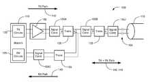
- FIG. 1illustrates a communication interface comprising two transformers in series, according to various embodiments of the invention.
- FIG. 2illustrates a TX Path of a dual-line-driver communication interface comprising two transformers in series, according to various embodiments of the invention.
- FIG. 3illustrates alternative embodiments of a communication interface including separate “high” and “low” band channels, according to various embodiments of the invention.
- FIG. 4illustrates alternative embodiments of a communication interface including a separate isolation transformer, according to various embodiments of the invention.
- FIG. 5illustrates alternative embodiments of a communication interface including separate “high” and “low” band channels wherein the channels are combined in a multi-tap transformer, according to various embodiments of the invention.
- FIG. 6illustrates methods of receiving a digitally encoded signal, according to various embodiments of the invention.
- FIG. 7illustrates methods of transmitting a digitally encoded signal, according to various embodiments of the invention
- digitally encoded signalsare passed through an AC (alternating current) power line.
- the same power linecan be used to both power an electronic system and to communicate between the electronic system and other devices.
- the digitally encoded signalsmay include video data, audio data, TCP/IP data, Ethernet data, or any other data type.
- the digitally encoded signalsare transmitted from and received by low voltage circuits that have both digital and analog sections. These circuits are typically developed on small geometry CMOS, BiCMOS, or similar technologies and have a limited range of allowable supply voltages for the digital and analog sections of the technology.
- digital sections of a communication systemmay be powered by 0.8V, 0.9V, 1V, 1.2V, 1.8V, 2.5V, 2.8V, 3.3V or 5V power supplies, amongst others.
- Analog and input/output (IO) sections of the communication systemmay be powered using different voltages.
- the digital sectionsmay operate from a 1V power supply while the analog circuits may operate from a 1.2V, 1.8V, 2.5V, 2.8V, 3.3V or 5V power supply, amongst others.
- the output of the low voltage circuitsis based on CMOS circuits and thus the signal is driven from a power supply (VDD) in the range of 1.8V to 5V, and, thus, in these examples it is only practically possible to output directly a differential linear signal considerably less than 2*VDD peak-to-peak.
- VDDpower supply
- 3.3V supplyit may only be possible to design circuitry that can create a linear signal with approximately 4.4V peak-to-peak.
- other technologies, with other power supply voltages, and other linear output signal voltagesmay be included in the low voltage circuits in alternative embodiments.
- the digitally encoded output of the low voltage circuitsis passed through a transmit path that includes coupling circuitry prior to introduction into a power line.
- the voltage of the signals introduced into the power lineare ⁇ 4 volts, ⁇ 6 volts, ⁇ 8 volts, ⁇ 10 volts, ⁇ 12 volts, ⁇ 14 volts, ⁇ 16 volts, ⁇ 18 volts, ⁇ 20 volts, or between any combinations of these voltages.
- the maximum peak-to-peak voltage of the digitally encoded signal injected into the power linemay be a function of industry standards, the regulatory requirements, a specific application, the implementation, and/or the like.
- the industry standard Homeplug AV 1.1allows a maximum Power Spectral Density (PSD) of ⁇ 50 dBm/Hz in the band between 1.8 MHz and 30 MHz.
- the final peak to-peak voltagemay depend on the implementation of the modem. For example, the Peak-to-Average ratio of an OFDM (orthogonal frequency division multiplexing) symbol may be restricted by clipping, to effect a valid range of equivalent peak-peak signals on the line.
- OFDMorthogonal frequency division multiplexing
- the receive pathmay include one or both of the transformers that are included in the transmit path.
- the receive pathincludes the same transformers as the transmit path.
- the peak-to-peak voltages of incoming signalsare optionally reduced by the same ratio as the transmitted signals are increased. For example, if the voltages of the transmitted signals are increased by four times then the received signals may be reduced by four times.
- the receive pathincludes one but not both of the transformers included in the transmit path.
- the transmit pathincludes two transformers with winding ratios of 1:2 and the receive path includes the second but not the first of these two transformers, then the peak-to-peak voltage of the received signals are reduced by approximately a factor of 2.
- a transformer included in both the transmit path and the receive pathis a multi-tap transformer and, thus, the winding ratio experienced along the transmit and receive paths at this transformer may be different.
- FIG. 1illustrates a Communication Interface 100 comprising two transformers in series, according to various embodiments of the invention.
- Communication Interface 100is disposed between a Power Line Modem 110 and a Power Line 115 and is configured to couple digitally encoded signals between these devices.
- Power Line Modem 110typically comprises TX (transmit) Circuits 120 and RX (receive) Circuits 125 .
- TX Circuits 120are an example of a signal source.
- TX Circuits 120 and RX Circuits 125include CMOS circuits configured to generate and receive signals using a 3.3V DC power supply (VDD).
- VDD3.3V DC power supply
- the TX Circuits 120generate a 2V peak-to-peak differential signal
- the TX Circuits 120generate a smaller or a larger signal according to their abilities.
- Communication Interface 100optionally further comprises a low voltage Line Driver 150 .
- Line Driver 150is typically a buffer, a transimpedance stage or a low gain (e.g. ⁇ 4 ⁇ or ⁇ 2 ⁇ ) amplifier that is configured to supply sufficient voltage and current to propagate signals into other elements of Communication Interface 100 .
- Line Driver 150is optionally disposed on the same semiconductor substrate as TX Circuits 120 .
- Line Driver 150is optionally integrated into the TX Circuits 120 .
- Line Driver 150is optionally powered by the same supply voltage as TX Circuits 120 .
- both TX Circuits 120 and Line Driver 150may be powered using the same 3.3V, 5V or the like.
- Power Line 115is configured to convey power.
- Power Line 115may include a 110 to 240V AC signal at 50 to 60 Hz. Electrical power from Power Line 115 is optionally used to power Power Line Modem 110 using circuits not shown.
- Communication Interface 100includes at least a Transformer 130 and a Transformer 135 .
- Transformer 130is disposed within a TX (transmit) Path 140 but optionally not a RX (receive) Path 145 .
- Transformer 135is in series with Transformer 130 with respect to the TX Path 140 , and is optionally also included in RX Path 145 .
- Transformer 130 and Transformer 135each have a primary to secondary winding ratio greater than one, e.g., less than or equal to 1:1.66 or 1:2 or 1:2.1.
- Transformer 130 and Transformer 135include winding ratios between approximately 1:1.5 and 1:4. In some embodiments, Transformer 130 and Transformer 135 include winding ratios between approximately 1:1.66 and 1:2.5.
- the winding ratios of Transformer 130 and Transformer 135are optionally different.
- Transformer 130is characterized by a winding ratio of 1:2.25 while Transformer 135 is characterized by a winding ratio of 1:2.
- the winding ratios of Transformer 130 and Transformer 135are optionally selected such that a signal generated by TX Circuits 120 is at least 4V peak-to-peak after passing through Transformer 135 .
- the resulting output of Transformer 135is between 4V and 6V, between 6V and 8V, between 8V and 10V, between 10V and 12V, between 12V and 14V, between 14V and 16V, between 16V and 18V, between 18V and 20V, or is configurable between 4V and 20V, peak-to-peak.
- Communication Interface 100optionally further includes one or more Signal Conditioners 155 , individually labeled 155 A . . . 155 J, etc.
- Signal Conditioners 155include active or passive filters or other signal modifying circuits.
- Signal Conditioner 155comprises a frequency dependent filter configured to separate the power signal of Power Line 115 at 50-60 Hz from digitally encoded signals at higher frequencies.
- Signal Conditioners 155are used to remove noise from the line that is below an operating band. In some embodiments, Signal Conditioners 155 are used to prevent unwanted out of band frequency signals in either the TX and/or RX pathways, such as those generated in the replica spectrum of a sampled system or those generated by some other signal source. For example, Signal Conditioners 155 may be configured to block signals associated with telephonic communication, cable television signals, digital subscriber line (DSL) communication, and/or the like. In some embodiments, Signal Conditioners 155 are configured to perform some protection task, such as current limiting or over-voltage protection. In some embodiments, Signal Conditioners 155 are used to impedance match the input to the output of other components to improve signal transfer and spectral response. In some embodiments, Signal Conditioners 155 are configured to separate signals in a high band from signals in a low band. Signal Conditioners 155 are optionally configured to achieve several of these functions.
- Communication Interface 100optionally further comprises one or more Coupling Capacitors 160 and other Signal Conditioner 155 J on the AC mains side of the last Transformer 135 .
- Signal Conditioner 155 Jcan include the Coupling Capacitors 160 or be transposed with Coupling Capacitors 160 in various configurations to safely couple the signals onto the Power Line 115 .
- Signal Conditioner 155 Jcan be passive and/or active, and can provide filtering or protection functions amongst other functions.
- the final Transformer 135is optionally configured to be of a voltage rating to provide secondary isolation from the AC mains.
- One of ordinary skill in the artwill understand that there are various alternative configurations that may be used to couple Communication Interface 100 to Power Line 115 .
- Communication Interface 100optionally further includes a Transformer 165 that is included in RX Path 145 .
- Transformer 165may include a winding ratio of one, a winding ratio greater than one, or a winding ratio less than one.
- the circuit configurations shown hereare differential in nature, but it will be easily understood that any section in either or both of the RX or TX paths may be single-ended.
- Communication Interface 100optionally includes one or more fuses, not shown.
- TX Path 140 and the RX Path 145are shown to separate between Transformer 130 and Signal Conditioner 155 B in FIG. 1 , these two signal paths may separate at other points within Communication Interface 100 in alternative embodiments. For example, between Line Driver 150 and Signal Conditioner 155 A, between Signal Conditioner 155 A and Transformer 130 , between Signal Conditioner 155 B and Transformer 135 , between Transformer 135 and Signal Conditioner 155 J, or between Signal Conditioner 155 J and Coupling Capacitors 160 . As shown elsewhere herein the separation point may include a transformer or a signal conditioner.
- FIG. 2illustrates the TX Path 140 of a multiple output single band communication interface implemented with a split TX pathway, comprising two transformers in series, according to various embodiments of the invention.
- TX Path 140includes a Multi-Tap Transformer 210 , optional Signal Conditioner 155 A, optional Signal Conditioner 155 D, and one, two or more optional Line Driver 150 , individually labeled 150 A . . . 150 B, etc.
- Each Line Driver 150is configured to drive signals responsive to circuitry in the TX Circuits 120 .
- the signals generated by Line Drivers 150are similar and result in an additive effect within Multi-Tap Transformer 210 , in order to further increase the injected power.
- Signal Conditioner 155 A and Signal Conditioner 155 Dare optionally the same.
- Line Driver 150 A and Line Driver 150 Bare optionally the same.
- the signals generated by Line Drivers 150are of different frequency, and Signal Conditioners 155 A and 155 D are configured to condition signals of different frequencies within the same transmission band and Line Drivers 150 A and 150 B may or may not be the same.
- Line Driver 150 Ais configured to drive signals in a first frequency range of a communication band while Line Driver 150 B is configured to drive signals in a second frequency range of the same communication band.
- Line Driver 150 Amay be configured to drive signals between 2 and 12 MHz while Line Driver 150 B is configured to drive signals between 12 and 30 MHz.
- both Line Drivers 150 A and 150 Bcommunicate complementary (e.g., interdependent) signals, the effective signal transmitted is effectively one interdependent signal between 2-30 MHz when the signal exits Multi-tap Transformer 210 .
- Multi-Tap Transformer 210may have the same winding ratios between each of the primary coils and the secondary coil, or may have different winding ratios. For example, in some embodiments, one of the primary coils may have an effective winding ratio of 1:2 while the other has an effective winding ratio of 1:2.5. In some embodiments Multi-Tap Transformer 210 includes more than two primary taps and is configured to receive signals from more than 2 Line Drivers 150 .
- RX Path 145is not shown in FIG. 2 for clarity, but optionally includes Transformer 135 but not Multi-Tap Transformer 210 .
- RX Path 145optionally includes an additional multi-tap transformer similar to Multi-Tap Transformer 210 .
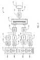
- FIG. 3illustrates alternative embodiments of Communication Interface 100 including separate “high” and “low” band channels in both TX Circuits 120 and RX Circuits 125 .
- the terms high band and low bandare used here to indicate the relative frequencies of each band and not their absolute frequency ranges.
- the high and low band channelsmay include any of the frequency ranges and combinations taught in the U.S. Patent applications cited herein. Typically each of these bands will include a distinct (although optionally overlapping) set of frequencies.
- Line Drivers 150are not shown for clarity.
- TX Circuits 120are divided into Low Band TX Circuits 120 A and High Band TX Circuits 120 B.
- Low Band TX Circuits 120 Aare configured to transmit digitally encoded signals in the low band and High Band TX Circuits 120 B are configured to transmit digitally encoded signals in the high band.
- the transmitted signalsare optionally passed through a line driver (not shown), signal conditioner 155 A and/or Transformer 130 before being received by a Signal Combiner 310 .
- RX Circuits 125are divided into High Band RX Circuits 125 B and Low Band RX Circuits 125 A, configured to receive digitally encoded signals in the high and low bands respectively.
- the received signalsare optionally received through Signal Conditioner 155 C, a Signal Conditioner 155 E and/or Transformer 165 .
- Signal Combiner 310is configured to combine and separate the high band and low band signals.
- Signal Combiner 310combines signals transmitted by Low Band TX Circuits 120 A and by High Band TX Circuits 120 B.
- Signal Combiner 310may include, for example, a multiplexer, a multi-tap transformer, a combination of high and low pass filters, a combination of band-pass and notch filters, a diplexer configured, or the like.
- Signal Combiner 310is combined with Transformer 135 .
- Another instance of Signal Conditioner 155is optionally disposed between Signal Combiner 310 and Transformer 135 . Separate instances of Signal Combiner 310 are optionally used for the low band and high band TX and RX signals.
- Transformers 130 used to transform the low band and high band signalsoptionally have different characteristics such as winding ratios, frequency profiles, impedance, and/or the like, respectively.
- optional Transformers 165 used to transform the low band and high band signalsoptionally have different characteristics such as winding ratios, frequency profiles, impedance, and/or the like, respectively.
- FIG. 4illustrates alternative embodiments of Communication Interface 100 including a separate Isolation Transformer 410 .
- Isolation Transformer 410is configured to isolate relatively large voltages found on Power Line 115 from other components of Communication Interface 100 .
- Isolation Transformer 410may have a winding ratio less than, equal to, or greater than one.
- Signal Conditioner 155 Jis optionally disposed between Isolation Transformer 410 and Transformer 135 .
- Signal Conditioner 155 Jmay be configured to block signals around 50-60 Hz and, thus, reduce the magnitude of voltages experienced by Transformer 135 .
- Isolation Transformer 410is optionally included in the other embodiments of Communication Interface 100 discussed herein.
- FIG. 5illustrates alternative embodiments of Communication Interface 100 wherein Transformer 135 is a multi-tap transformer.
- transmitted signalsare coupled through a First Primary Winding (P 1 ) and received signals are coupled through a Second Primary Winding (P 2 ). All of these signals are coupled through a Secondary Winding (S).
- the ratio of P 1 :Smay be greater than, the same as, or less than the ratio P 2 :S.
- P 1 :Sis 1:4 while P 2 :S is 2:4, approximately.
- P 2 :Smay be two or more times greater than P 1 :S.
- additional elementssuch as Transformer 165 , are optional in the embodiments illustrated by FIG. 5 .
- FIG. 6illustrates methods of receiving a digitally encoded signal, according to various embodiments of the invention. These methods are discussed generally in relation to the embodiments of Communication Interface 100 illustrated by FIG. 1 . However, it will be apparent to those skilled in the art that the methods illustrated by FIG. 6 can be adapted to other embodiments of Communication Interface 100 illustrated herein. These adaptations will include steps relating to passing signals through one or more of the components illustrated in, for example, FIGS. 2-5 .
- a digitally encoded signalis received from Power Line 115 .
- This signalmay be received from another device as part of a network communication.
- This other devicemay include an embodiment of Communication Interface 100 .
- the received signalmay include network communication protocols such as telephone exchange, TCP/IP or Ethernet protocols.
- a First Transform Step 620the digitally encoded signal is transformed to a lower peak-to-peak voltage using Transformer 135 .
- Condition Signal Step 630the received signal is conditioned using Signal Conditioner 155 B.
- Condition Signal Step 630may include separating signals at the frequency at which power is transmitted through Power Line 115 from signals that include digitally encoded data at different frequencies.
- the received and optionally conditioned signalis transformed again using Transformer 165 .
- this transformationresults in a signal having a lower peak-to-peak voltage, approximately the same peak-to-peak voltage, or a greater peak-to-peak voltage.
- the signalis conditioned using Signal Conditioner 155 C.
- this conditioningis configured to separate signals in different frequency bands.
- RX Circuits 125may be used to decode the digitally encoded information within the received signals.
- RX Circuitsmay generate digital data representative of the encoded information using an analog to digital converter.
- FIG. 7illustrates methods of transmitting a digitally encoded signal, according to various embodiments of the invention. These methods are discussed generally in relation to the embodiments of Communication Interface 100 illustrated by FIG. 1 . However, it will be apparent to those skilled in the art that the methods illustrated by FIG. 7 can be adapted to other embodiments of Communication Interface 100 illustrated herein. These adaptations will include steps relating to passing signals through one or more of the components illustrated in, for example, FIGS. 2-5 .
- TX Circuits 120are used to generate a signal including digitally encoded information.
- this informationis received from a computing device using Communication Interface 100 to communicate with other devices via Power Line 115 .
- the generated signalmay include network communication protocols such as telephone exchange, TCP/IP or Ethernet protocols.
- Line Driver 150is used to provide the signal at an appropriate voltage, current, impedance and/or the like.
- Drive Step 720optionally includes amplifying the signal generated by TX Circuits 120 .
- Signal Conditioner 155 Ais used to condition the signal from Line Driver 150 .
- a First Transform Step 740the signal is transformed using Transformer 130 . This transformation includes increasing the peak-to-peak voltage of the signal.
- Condition Signal Step 750the signal transformed using Transformer 130 is conditioned using Signal Conditioner 155 B.
- a Second Transform Step 760the signal is transformed for a second time using Transformer 135 .
- This stepincludes further increasing the peak-to-peak voltage of the signal. Examples of the resulting peak-to-peak voltages are provided elsewhere herein.
- Couple Step 770the signal is coupled into Power Line 115 using Coupling Capacitors 160 .
- the methods illustrated by FIG. 7are optionally performed in response to receiving a signal using the methods illustrated by FIG. 6 .
- a computing devicemay receive data from Power Line 115 using Communication Interface 100 and in response to this data send different data to another computing device using Communication Interface 100 and Power Line 115 .
- the received and transmitted signalsare optionally in different frequency bands. Further, steps of separating or combining signals in different frequency ranges using embodiments of Signal Conditioner 155 and/or Signal Combiner 310 may occur in the embodiments illustrated by FIGS. 6 and 7 .
Landscapes
- Engineering & Computer Science (AREA)
- Power Engineering (AREA)
- Computer Networks & Wireless Communication (AREA)
- Signal Processing (AREA)
- Dc Digital Transmission (AREA)
- Cable Transmission Systems, Equalization Of Radio And Reduction Of Echo (AREA)
Abstract
Description
Claims (20)
Priority Applications (1)
| Application Number | Priority Date | Filing Date | Title |
|---|---|---|---|
| PCT/US2009/048124WO2010008788A2 (en) | 2008-06-23 | 2009-06-22 | Dual transformer communication interface |
Applications Claiming Priority (5)
| Application Number | Priority Date | Filing Date | Title |
|---|---|---|---|
| US11/493,292US8885814B2 (en) | 2006-07-25 | 2006-07-25 | Feedback impedance control for driving a signal |
| US11/467,141US7899436B2 (en) | 2005-10-03 | 2006-08-24 | Multi-wideband communications over power lines |
| US11/752,865US8213895B2 (en) | 2005-10-03 | 2007-05-23 | Multi-wideband communications over multiple mediums within a network |
| US11/855,081US7417463B1 (en) | 2007-09-13 | 2007-09-13 | Wireline transmission circuit |
| US12/075,888US8213582B2 (en) | 2008-03-14 | 2008-03-14 | Coupling signal processing circuitry with a wireline communications medium |
Publications (2)
| Publication Number | Publication Date |
|---|---|
| US20090315700A1 US20090315700A1 (en) | 2009-12-24 |
| US9705562B2true US9705562B2 (en) | 2017-07-11 |
Family
ID=59268391
Family Applications (1)
| Application Number | Title | Priority Date | Filing Date |
|---|---|---|---|
| US12/144,511Active2033-10-22US9705562B2 (en) | 2006-07-25 | 2008-06-23 | Dual transformer communication interface |
Country Status (1)
| Country | Link |
|---|---|
| US (1) | US9705562B2 (en) |
Families Citing this family (12)
| Publication number | Priority date | Publication date | Assignee | Title |
|---|---|---|---|---|
| US7808985B2 (en)* | 2006-11-21 | 2010-10-05 | Gigle Networks Sl | Network repeater |
| US20110205918A1 (en)* | 2005-10-03 | 2011-08-25 | Hurwitz Jonathan E D | Apparatus for Power Line and Wireless Communications |
| EP1770870B1 (en)* | 2005-10-03 | 2019-04-03 | Avago Technologies International Sales Pte. Limited | Powerline communication device and method |
| US20080159358A1 (en)* | 2007-01-02 | 2008-07-03 | David Ruiz | Unknown Destination Traffic Repetition |
| US8213895B2 (en) | 2005-10-03 | 2012-07-03 | Broadcom Europe Limited | Multi-wideband communications over multiple mediums within a network |
| US8520715B2 (en)* | 2006-07-06 | 2013-08-27 | Broadcom Corporation | Adaptative multi-carrier code division multiple access |
| US8885814B2 (en)* | 2006-07-25 | 2014-11-11 | Broadcom Europe Limited | Feedback impedance control for driving a signal |
| US8213582B2 (en)* | 2008-03-14 | 2012-07-03 | Broadcom Europe Limited | Coupling signal processing circuitry with a wireline communications medium |
| US8810059B2 (en)* | 2010-04-29 | 2014-08-19 | Texas Instruments Incorporated | Effective low voltage to medium voltage transmission on PRIME band |
| US9325374B2 (en) | 2012-06-15 | 2016-04-26 | Qualcomm Incorporated | Powerline communication diversity coupling technique |
| US9294151B2 (en)* | 2012-12-12 | 2016-03-22 | Oceaneering International, Inc. | Wireless data transmission via inductive coupling using di/dt as the magnetic modulation scheme and hysteresis |
| TWI641253B (en)* | 2016-12-06 | 2018-11-11 | 瑞昱半導體股份有限公司 | Network driving circuit and method of driving network device |
Citations (92)
| Publication number | Priority date | Publication date | Assignee | Title |
|---|---|---|---|---|
| US3696383A (en)* | 1970-01-17 | 1972-10-03 | Tokyo Electric Power Co | Information transmission system for metered magnitudes |
| US3962547A (en)* | 1975-05-27 | 1976-06-08 | Westinghouse Electric Corporation | Repeater coupler for power line communication systems |
| US4038601A (en)* | 1974-02-18 | 1977-07-26 | Societe Nationale Industrielle Aerospatiale | Device for connecting peripheral units to a line for transmitting data by pulse code modulation |
| US4066912A (en)* | 1976-04-21 | 1978-01-03 | General Electric Company | Coupling arrangement for power line carrier systems |
| US4210901A (en)* | 1977-04-25 | 1980-07-01 | Westinghouse Electric Corp. | Signal repeater for a distribution network communication system |
| US4504705A (en)* | 1982-01-18 | 1985-03-12 | Lgz Landis & Gyr Zug Ag | Receiving arrangements for audio frequency signals |
| US4636711A (en) | 1984-12-04 | 1987-01-13 | Airborne Electronics, Inc. | Pulse width modulation control circuit with a variable zero to one hundred percent duty cycle |
| US4697166A (en)* | 1986-08-11 | 1987-09-29 | Nippon Colin Co., Ltd. | Method and apparatus for coupling transceiver to power line carrier system |
| US4772870A (en) | 1986-11-20 | 1988-09-20 | Reyes Ronald R | Power line communication system |
| US4864589A (en)* | 1985-07-24 | 1989-09-05 | Nec Home Electronics Ltd. | Spread spectrum power line communications |
| US4973940A (en)* | 1987-07-08 | 1990-11-27 | Colin Electronics Co., Ltd. | Optimum impedance system for coupling transceiver to power line carrier network |
| US5066939A (en)* | 1989-10-04 | 1991-11-19 | Mansfield Jr Amos R | Method and means of operating a power line carrier communication system |
| US5210519A (en)* | 1990-06-22 | 1993-05-11 | British Aerospace Public Limited Company | Digital data transmission |
| US5289199A (en)* | 1989-06-22 | 1994-02-22 | Texas Instruments Deutschland Gmbh | Antenna resonant circuit |
| US5406249A (en)* | 1993-03-09 | 1995-04-11 | Metricom, Inc. | Method and structure for coupling power-line carrier current signals using common-mode coupling |
| US5559377A (en)* | 1989-04-28 | 1996-09-24 | Abraham; Charles | Transformer coupler for communication over various lines |
| US5574748A (en) | 1989-08-23 | 1996-11-12 | Intellon Corporation | Spread spectrum communications system for network |
| US5770996A (en)* | 1996-08-30 | 1998-06-23 | Interactive Technologies, Inc. | Transformer system for power line communications |
| US5777544A (en) | 1997-03-17 | 1998-07-07 | Intellon Corporation | Apparatus and method for controlling data communications having combination of wide and narrow band frequency protocols |
| US5796604A (en)* | 1994-04-22 | 1998-08-18 | Sgs-Thomson Microelectronics, S.A. | System comprising a machine for the communication of pricing changes |
| US5929750A (en) | 1992-10-22 | 1999-07-27 | Norweb Plc | Transmission network and filter therefor |
| US6014386A (en) | 1989-10-30 | 2000-01-11 | Videocom, Inc. | System and method for high speed communication of video, voice and error-free data over in-wall wiring |
| US6243413B1 (en) | 1998-04-03 | 2001-06-05 | International Business Machines Corporation | Modular home-networking communication system and method using disparate communication channels |
| EP1134909A1 (en) | 2000-03-14 | 2001-09-19 | Biwave Technologies | Single-cable transmission device for signals and power supply of a surveillance system |
| US6313738B1 (en)* | 1997-06-09 | 2001-11-06 | At&T Corp. | Adaptive noise cancellation system |
| WO2001095518A2 (en) | 2000-06-07 | 2001-12-13 | Conexant Systems, Inc. | Method and apparatus for dual-band modulation in powerline communication network systems |
| US6373377B1 (en) | 2000-10-05 | 2002-04-16 | Conexant Systems, Inc. | Power supply with digital data coupling for power-line networking |
| US6396392B1 (en)* | 2000-05-23 | 2002-05-28 | Wire21, Inc. | High frequency network communications over various lines |
| US6407987B1 (en)* | 1989-04-28 | 2002-06-18 | Wire21, Inc. | Transformer coupler for communication over various lines |
| US20020154000A1 (en) | 2001-02-14 | 2002-10-24 | Kline Paul A. | Data communication over a power line |
| US20030016123A1 (en) | 2000-03-24 | 2003-01-23 | Wolfgang Tager | Powerline data communication |
| WO2003015291A2 (en) | 2001-08-04 | 2003-02-20 | Enikia Llc | Frequency management and policing |
| US20030122473A1 (en) | 2001-12-29 | 2003-07-03 | Lg Electronics Inc. | Structure of projection television and producing method thereof |
| US20030129978A1 (en) | 2001-11-27 | 2003-07-10 | Sony Corporation | Communication system, communication terminal and communication method |
| US20030169155A1 (en) | 2000-04-14 | 2003-09-11 | Mollenkopf James Douglas | Power line communication system and method of using the same |
| WO2003077443A1 (en) | 2002-03-12 | 2003-09-18 | Philips Intellectual Property & Standards Gmbh | Repeater for power line communication system |
| US6633228B1 (en)* | 1999-02-22 | 2003-10-14 | Siemens Aktiengesellschaft | Communication system for simultaneous two-channel transmission of data between subscribers |
| WO2003092212A1 (en) | 2002-04-25 | 2003-11-06 | Raytheon Company | An adaptive air interface waveform |
| US20030224728A1 (en) | 2002-06-03 | 2003-12-04 | Tomi Heinonen | Bluetooth access point and remote bluetooth modules for powerline based networking |
| US6686832B2 (en)* | 2000-05-23 | 2004-02-03 | Satius, Inc. | High frequency network multiplexed communications over various lines |
| EP1388954A2 (en) | 2001-04-19 | 2004-02-11 | Diseno de Sistemas en Silicio S.A. | Method for multiple access and transmission in a point-to-multipoint system on an electrical network |
| US20040047427A1 (en) | 2000-12-20 | 2004-03-11 | Klaus Dostert | Method and device for transmitting data on at least one electrical power supply line |
| US20040056734A1 (en)* | 2001-05-18 | 2004-03-25 | Davidow Clifford A. | Medium voltage signal coupling structure for last leg power grid high-speed data network |
| US20040107588A1 (en) | 2002-12-06 | 2004-06-10 | Jian-Hua Pu | Laser meter |
| US20040113756A1 (en) | 2002-12-10 | 2004-06-17 | Mollenkopf James Douglas | Device and method for coupling with electrical distribution network infrastructure to provide communications |
| US20040113757A1 (en) | 2002-12-10 | 2004-06-17 | White Melvin Joseph | Power line communication system and method of operating the same |
| US20040174851A1 (en) | 2001-07-17 | 2004-09-09 | Yeshayahu Zalitzky | Dual purpose power line modem |
| US6809633B2 (en)* | 2001-03-29 | 2004-10-26 | Ambient Corporation | Coupling broadband modems to power lines |
| WO2004100392A1 (en) | 2003-04-30 | 2004-11-18 | Spidcom Technologies | Method for transmitting data by means of a carrier current |
| US20040246107A1 (en) | 2001-02-14 | 2004-12-09 | Current Technologies, L.L.C. | Power line communication system and method of using the same |
| US20040263282A1 (en)* | 2003-03-19 | 2004-12-30 | Takashi Kaku | Modem coupling circuit for power-line carrier |
| US6844810B2 (en)* | 2002-10-17 | 2005-01-18 | Ambient Corporation | Arrangement of a data coupler for power line communications |
| US20050089061A1 (en) | 2003-08-28 | 2005-04-28 | Oleg Logvinov | Joint powerline/ultra-wide band system |
| WO2005039070A2 (en) | 2003-10-15 | 2005-04-28 | General Electric Company | Compensating for dynamic nulls in a power line communication system |
| EP1531568A1 (en) | 2002-08-23 | 2005-05-18 | Matsushita Electric Industrial Co., Ltd. | Ofdm-cdma transmission device and ofdm-cdma transmission method |
| EP1548974A2 (en) | 2003-12-25 | 2005-06-29 | NTT DoCoMo, Inc. | Radio communication system, transmitter, receiver and radio communicating method |
| US20050141473A1 (en) | 2003-12-27 | 2005-06-30 | Kwang-Jae Lim | Adaptive downlink packet transmission method in multicarrier CDMA system |
| US6922135B2 (en)* | 2000-05-23 | 2005-07-26 | Satius, Inc. | High frequency network multiplexed communications over various lines using multiple modulated carrier frequencies |
| EP1432138B1 (en) | 2002-12-19 | 2005-09-28 | Laboratoire Europeen ADSL | Digital data distribution method and system |
| US20050231036A1 (en)* | 2002-04-30 | 2005-10-20 | Moon-Young No | Adapter for communicating over power line |
| US6958680B2 (en)* | 2000-04-14 | 2005-10-25 | Current Technologies, Llc | Power line communication system and method of using the same |
| US6975843B2 (en)* | 2000-12-21 | 2005-12-13 | Telefonaktiebolaget L M Ericsson (Publ) | Method and an arrangement relating to telecommunications systems |
| US6985715B2 (en) | 2003-05-29 | 2006-01-10 | Amperion, Inc. | Method and device for frequency translation in powerline communications |
| WO2006017743A2 (en) | 2004-08-04 | 2006-02-16 | Quadlogic Controls Corporation | Method and system for radio-frequency signal coupling to medium tension power lines with auto-tuning device |
| US20060097574A1 (en) | 2004-10-26 | 2006-05-11 | Gidge Brett D | Power line communications device and method of use |
| US7053756B2 (en) | 2001-12-21 | 2006-05-30 | Current Technologies, Llc | Facilitating communication of data signals on electric power systems |
| US20060120399A1 (en) | 2003-06-18 | 2006-06-08 | Claret Jorge V B | Method enabling multiple communication nodes to access a transmission means on an electrical grid |
| US20060126617A1 (en) | 2004-12-15 | 2006-06-15 | Cregg Daniel B | Mesh network of intelligent devices communicating via powerline and radio frequency |
| US7075414B2 (en) | 2003-05-13 | 2006-07-11 | Current Technologies, Llc | Device and method for communicating data signals through multiple power line conductors |
| WO2006074174A1 (en) | 2005-01-03 | 2006-07-13 | Demian Martin | Alternating current power strip with network repeating and management |
| US20060269001A1 (en)* | 2005-05-26 | 2006-11-30 | Sony Corporation, A Japanese Corporation | Ac plc to dc plc transceiver |
| US7170367B2 (en)* | 2004-10-25 | 2007-01-30 | Ambient Corporation | Inductive coupler for power line communications |
| US7173938B1 (en)* | 2001-05-18 | 2007-02-06 | Current Grid, Llc | Method and apparatus for processing outbound data within a powerline based communication system |
| US20070076666A1 (en) | 2005-10-03 | 2007-04-05 | Riveiro Juan C | Multi-Wideband Communications over Power Lines |
| US20070149258A1 (en)* | 2005-12-28 | 2007-06-28 | Matsushita Electric Industrial Co., Ltd. | Power supplying apparatus, power line communication apparatus, power line communication system, and power supplying method |
| EP1351408B1 (en) | 2000-12-18 | 2007-08-08 | Diseno de Sistemas en Silicio S.A. | Digital point-to-multipoint data transmission system on an electric network |
| US7276814B2 (en)* | 2002-01-02 | 2007-10-02 | Ruggedcom Inc. | Environmentally hardened ethernet switch |
| US20070229231A1 (en) | 2005-10-03 | 2007-10-04 | Hurwitz Jonathan E D | Multi-Wideband Communications over Multiple Mediums within a Network |
| US7333003B1 (en)* | 2007-04-24 | 2008-02-19 | Telkonet, Inc. | Power line coupler adapted for use with multiple electric power meters |
| US20080043992A1 (en) | 2006-07-25 | 2008-02-21 | Gigle Semiconductor Inc. | Feedback impedance control for driving a signal |
| US20080107242A1 (en)* | 2004-12-24 | 2008-05-08 | Matsushita Electric Industrial Co., Ltd. | Line Status Detection Apparatus, Communication Apparatus, and Line Status Detection Method |
| US20080130640A1 (en) | 2005-10-03 | 2008-06-05 | Jonathan Ephraim David Hurwitz | Multi-Wideband Communications over Multiple Mediums |
| US7391317B2 (en) | 2004-09-08 | 2008-06-24 | Satius, Inc. | Apparatus and method for transmitting digital data over various communication media |
| US20080159358A1 (en) | 2007-01-02 | 2008-07-03 | David Ruiz | Unknown Destination Traffic Repetition |
| JP2008227837A (en)* | 2007-03-12 | 2008-09-25 | Matsushita Electric Works Ltd | Power line communication device and connection circuit for power line communication device |
| US20080304577A1 (en)* | 2007-05-30 | 2008-12-11 | Matsushita Electric Industrial Co., Ltd. | Power-line communication method, power-line communication device, and power-line communication system |
| US20090232286A1 (en) | 2008-03-14 | 2009-09-17 | Gigle Semiconductor, Ltd. | Coupling signal processing circuitry with a wireline communications medium |
| US7602220B1 (en) | 2008-06-24 | 2009-10-13 | Gigle Semiconductor, Ltd. | Resistor-input transconductor including common-mode compensation |
| US20100246648A1 (en)* | 2009-02-12 | 2010-09-30 | David Gimenez Rocamora | External AC-DC Coupling for Communication Interfaces |
| US7808985B2 (en) | 2006-11-21 | 2010-10-05 | Gigle Networks Sl | Network repeater |
| US7860146B2 (en) | 2006-07-06 | 2010-12-28 | Gigle Networks, Inc. | Adaptative multi-carrier code division multiple access |
| US7899436B2 (en) | 2005-10-03 | 2011-03-01 | Juan Carlos Riveiro | Multi-wideband communications over power lines |
- 2008
- 2008-06-23USUS12/144,511patent/US9705562B2/enactiveActive
Patent Citations (102)
| Publication number | Priority date | Publication date | Assignee | Title |
|---|---|---|---|---|
| US3696383A (en)* | 1970-01-17 | 1972-10-03 | Tokyo Electric Power Co | Information transmission system for metered magnitudes |
| US4038601A (en)* | 1974-02-18 | 1977-07-26 | Societe Nationale Industrielle Aerospatiale | Device for connecting peripheral units to a line for transmitting data by pulse code modulation |
| US3962547A (en)* | 1975-05-27 | 1976-06-08 | Westinghouse Electric Corporation | Repeater coupler for power line communication systems |
| US4066912A (en)* | 1976-04-21 | 1978-01-03 | General Electric Company | Coupling arrangement for power line carrier systems |
| US4210901A (en)* | 1977-04-25 | 1980-07-01 | Westinghouse Electric Corp. | Signal repeater for a distribution network communication system |
| US4504705A (en)* | 1982-01-18 | 1985-03-12 | Lgz Landis & Gyr Zug Ag | Receiving arrangements for audio frequency signals |
| US4636711A (en) | 1984-12-04 | 1987-01-13 | Airborne Electronics, Inc. | Pulse width modulation control circuit with a variable zero to one hundred percent duty cycle |
| US4864589A (en)* | 1985-07-24 | 1989-09-05 | Nec Home Electronics Ltd. | Spread spectrum power line communications |
| US4697166A (en)* | 1986-08-11 | 1987-09-29 | Nippon Colin Co., Ltd. | Method and apparatus for coupling transceiver to power line carrier system |
| US4772870A (en) | 1986-11-20 | 1988-09-20 | Reyes Ronald R | Power line communication system |
| US4973940A (en)* | 1987-07-08 | 1990-11-27 | Colin Electronics Co., Ltd. | Optimum impedance system for coupling transceiver to power line carrier network |
| US5559377A (en)* | 1989-04-28 | 1996-09-24 | Abraham; Charles | Transformer coupler for communication over various lines |
| US6407987B1 (en)* | 1989-04-28 | 2002-06-18 | Wire21, Inc. | Transformer coupler for communication over various lines |
| US5289199A (en)* | 1989-06-22 | 1994-02-22 | Texas Instruments Deutschland Gmbh | Antenna resonant circuit |
| US5574748A (en) | 1989-08-23 | 1996-11-12 | Intellon Corporation | Spread spectrum communications system for network |
| US5066939A (en)* | 1989-10-04 | 1991-11-19 | Mansfield Jr Amos R | Method and means of operating a power line carrier communication system |
| US6014386A (en) | 1989-10-30 | 2000-01-11 | Videocom, Inc. | System and method for high speed communication of video, voice and error-free data over in-wall wiring |
| US5210519A (en)* | 1990-06-22 | 1993-05-11 | British Aerospace Public Limited Company | Digital data transmission |
| US5929750A (en) | 1992-10-22 | 1999-07-27 | Norweb Plc | Transmission network and filter therefor |
| US5933071A (en) | 1992-10-22 | 1999-08-03 | Norweb Plc | Electricity distribution and/or power transmission network and filter for telecommunication over power lines |
| US5406249A (en)* | 1993-03-09 | 1995-04-11 | Metricom, Inc. | Method and structure for coupling power-line carrier current signals using common-mode coupling |
| US5796604A (en)* | 1994-04-22 | 1998-08-18 | Sgs-Thomson Microelectronics, S.A. | System comprising a machine for the communication of pricing changes |
| US5770996A (en)* | 1996-08-30 | 1998-06-23 | Interactive Technologies, Inc. | Transformer system for power line communications |
| US5777544A (en) | 1997-03-17 | 1998-07-07 | Intellon Corporation | Apparatus and method for controlling data communications having combination of wide and narrow band frequency protocols |
| US6313738B1 (en)* | 1997-06-09 | 2001-11-06 | At&T Corp. | Adaptive noise cancellation system |
| US6243413B1 (en) | 1998-04-03 | 2001-06-05 | International Business Machines Corporation | Modular home-networking communication system and method using disparate communication channels |
| US6633228B1 (en)* | 1999-02-22 | 2003-10-14 | Siemens Aktiengesellschaft | Communication system for simultaneous two-channel transmission of data between subscribers |
| EP1134909A1 (en) | 2000-03-14 | 2001-09-19 | Biwave Technologies | Single-cable transmission device for signals and power supply of a surveillance system |
| US20030016123A1 (en) | 2000-03-24 | 2003-01-23 | Wolfgang Tager | Powerline data communication |
| US20030169155A1 (en) | 2000-04-14 | 2003-09-11 | Mollenkopf James Douglas | Power line communication system and method of using the same |
| US6958680B2 (en)* | 2000-04-14 | 2005-10-25 | Current Technologies, Llc | Power line communication system and method of using the same |
| US6396392B1 (en)* | 2000-05-23 | 2002-05-28 | Wire21, Inc. | High frequency network communications over various lines |
| US6686832B2 (en)* | 2000-05-23 | 2004-02-03 | Satius, Inc. | High frequency network multiplexed communications over various lines |
| US6922135B2 (en)* | 2000-05-23 | 2005-07-26 | Satius, Inc. | High frequency network multiplexed communications over various lines using multiple modulated carrier frequencies |
| WO2001095518A2 (en) | 2000-06-07 | 2001-12-13 | Conexant Systems, Inc. | Method and apparatus for dual-band modulation in powerline communication network systems |
| US6373377B1 (en) | 2000-10-05 | 2002-04-16 | Conexant Systems, Inc. | Power supply with digital data coupling for power-line networking |
| EP1351408B1 (en) | 2000-12-18 | 2007-08-08 | Diseno de Sistemas en Silicio S.A. | Digital point-to-multipoint data transmission system on an electric network |
| US20040047427A1 (en) | 2000-12-20 | 2004-03-11 | Klaus Dostert | Method and device for transmitting data on at least one electrical power supply line |
| US6975843B2 (en)* | 2000-12-21 | 2005-12-13 | Telefonaktiebolaget L M Ericsson (Publ) | Method and an arrangement relating to telecommunications systems |
| US20040246107A1 (en) | 2001-02-14 | 2004-12-09 | Current Technologies, L.L.C. | Power line communication system and method of using the same |
| US20020154000A1 (en) | 2001-02-14 | 2002-10-24 | Kline Paul A. | Data communication over a power line |
| US7042351B2 (en) | 2001-02-14 | 2006-05-09 | Current Technologies, Llc | Data communication over a power line |
| US6809633B2 (en)* | 2001-03-29 | 2004-10-26 | Ambient Corporation | Coupling broadband modems to power lines |
| EP1388954A2 (en) | 2001-04-19 | 2004-02-11 | Diseno de Sistemas en Silicio S.A. | Method for multiple access and transmission in a point-to-multipoint system on an electrical network |
| US20070222637A1 (en)* | 2001-05-18 | 2007-09-27 | Davidow Clifford A | Medium Voltage Signal Coupling Structure For Last Leg Power Grid High-Speed Data Network |
| US20040056734A1 (en)* | 2001-05-18 | 2004-03-25 | Davidow Clifford A. | Medium voltage signal coupling structure for last leg power grid high-speed data network |
| US7173938B1 (en)* | 2001-05-18 | 2007-02-06 | Current Grid, Llc | Method and apparatus for processing outbound data within a powerline based communication system |
| US7773361B2 (en)* | 2001-05-18 | 2010-08-10 | Current Grid, Llc | Medium voltage signal coupling structure for last leg power grid high-speed data network |
| US20040174851A1 (en) | 2001-07-17 | 2004-09-09 | Yeshayahu Zalitzky | Dual purpose power line modem |
| WO2003015291A2 (en) | 2001-08-04 | 2003-02-20 | Enikia Llc | Frequency management and policing |
| US20030129978A1 (en) | 2001-11-27 | 2003-07-10 | Sony Corporation | Communication system, communication terminal and communication method |
| US7053756B2 (en) | 2001-12-21 | 2006-05-30 | Current Technologies, Llc | Facilitating communication of data signals on electric power systems |
| US20030122473A1 (en) | 2001-12-29 | 2003-07-03 | Lg Electronics Inc. | Structure of projection television and producing method thereof |
| US7443054B2 (en)* | 2002-01-02 | 2008-10-28 | Ruggedcom Inc. | Environmentally hardened Ethernet switch |
| US7276814B2 (en)* | 2002-01-02 | 2007-10-02 | Ruggedcom Inc. | Environmentally hardened ethernet switch |
| WO2003077443A1 (en) | 2002-03-12 | 2003-09-18 | Philips Intellectual Property & Standards Gmbh | Repeater for power line communication system |
| WO2003092212A1 (en) | 2002-04-25 | 2003-11-06 | Raytheon Company | An adaptive air interface waveform |
| US20050231036A1 (en)* | 2002-04-30 | 2005-10-20 | Moon-Young No | Adapter for communicating over power line |
| US20030224728A1 (en) | 2002-06-03 | 2003-12-04 | Tomi Heinonen | Bluetooth access point and remote bluetooth modules for powerline based networking |
| EP1531568A1 (en) | 2002-08-23 | 2005-05-18 | Matsushita Electric Industrial Co., Ltd. | Ofdm-cdma transmission device and ofdm-cdma transmission method |
| US6844810B2 (en)* | 2002-10-17 | 2005-01-18 | Ambient Corporation | Arrangement of a data coupler for power line communications |
| US20040107588A1 (en) | 2002-12-06 | 2004-06-10 | Jian-Hua Pu | Laser meter |
| US20040113757A1 (en) | 2002-12-10 | 2004-06-17 | White Melvin Joseph | Power line communication system and method of operating the same |
| US6980091B2 (en)* | 2002-12-10 | 2005-12-27 | Current Technologies, Llc | Power line communication system and method of operating the same |
| US20040113756A1 (en) | 2002-12-10 | 2004-06-17 | Mollenkopf James Douglas | Device and method for coupling with electrical distribution network infrastructure to provide communications |
| US7466225B2 (en)* | 2002-12-10 | 2008-12-16 | Current Technologies, Llc | Power line communication system and method of operating the same |
| US20060038662A1 (en) | 2002-12-10 | 2006-02-23 | White Melvin J Ii | Power line communication system and method of operating the same |
| EP1432138B1 (en) | 2002-12-19 | 2005-09-28 | Laboratoire Europeen ADSL | Digital data distribution method and system |
| US20040263282A1 (en)* | 2003-03-19 | 2004-12-30 | Takashi Kaku | Modem coupling circuit for power-line carrier |
| US7019611B2 (en)* | 2003-03-19 | 2006-03-28 | Honda Electron Co., Ltd. | Modem coupling circuit for power-line carrier |
| WO2004100392A1 (en) | 2003-04-30 | 2004-11-18 | Spidcom Technologies | Method for transmitting data by means of a carrier current |
| US7075414B2 (en) | 2003-05-13 | 2006-07-11 | Current Technologies, Llc | Device and method for communicating data signals through multiple power line conductors |
| US6985715B2 (en) | 2003-05-29 | 2006-01-10 | Amperion, Inc. | Method and device for frequency translation in powerline communications |
| US20060120399A1 (en) | 2003-06-18 | 2006-06-08 | Claret Jorge V B | Method enabling multiple communication nodes to access a transmission means on an electrical grid |
| US20050089061A1 (en) | 2003-08-28 | 2005-04-28 | Oleg Logvinov | Joint powerline/ultra-wide band system |
| WO2005039070A2 (en) | 2003-10-15 | 2005-04-28 | General Electric Company | Compensating for dynamic nulls in a power line communication system |
| EP1548974A2 (en) | 2003-12-25 | 2005-06-29 | NTT DoCoMo, Inc. | Radio communication system, transmitter, receiver and radio communicating method |
| US20050141473A1 (en) | 2003-12-27 | 2005-06-30 | Kwang-Jae Lim | Adaptive downlink packet transmission method in multicarrier CDMA system |
| WO2006017743A2 (en) | 2004-08-04 | 2006-02-16 | Quadlogic Controls Corporation | Method and system for radio-frequency signal coupling to medium tension power lines with auto-tuning device |
| US7391317B2 (en) | 2004-09-08 | 2008-06-24 | Satius, Inc. | Apparatus and method for transmitting digital data over various communication media |
| US7170367B2 (en)* | 2004-10-25 | 2007-01-30 | Ambient Corporation | Inductive coupler for power line communications |
| US20060097574A1 (en) | 2004-10-26 | 2006-05-11 | Gidge Brett D | Power line communications device and method of use |
| US20060126617A1 (en) | 2004-12-15 | 2006-06-15 | Cregg Daniel B | Mesh network of intelligent devices communicating via powerline and radio frequency |
| US20080107242A1 (en)* | 2004-12-24 | 2008-05-08 | Matsushita Electric Industrial Co., Ltd. | Line Status Detection Apparatus, Communication Apparatus, and Line Status Detection Method |
| WO2006074174A1 (en) | 2005-01-03 | 2006-07-13 | Demian Martin | Alternating current power strip with network repeating and management |
| US20060269001A1 (en)* | 2005-05-26 | 2006-11-30 | Sony Corporation, A Japanese Corporation | Ac plc to dc plc transceiver |
| US20070229231A1 (en) | 2005-10-03 | 2007-10-04 | Hurwitz Jonathan E D | Multi-Wideband Communications over Multiple Mediums within a Network |
| US20080130640A1 (en) | 2005-10-03 | 2008-06-05 | Jonathan Ephraim David Hurwitz | Multi-Wideband Communications over Multiple Mediums |
| US7899436B2 (en) | 2005-10-03 | 2011-03-01 | Juan Carlos Riveiro | Multi-wideband communications over power lines |
| US20070076666A1 (en) | 2005-10-03 | 2007-04-05 | Riveiro Juan C | Multi-Wideband Communications over Power Lines |
| US20070149258A1 (en)* | 2005-12-28 | 2007-06-28 | Matsushita Electric Industrial Co., Ltd. | Power supplying apparatus, power line communication apparatus, power line communication system, and power supplying method |
| US7853237B2 (en)* | 2005-12-28 | 2010-12-14 | Panasonic Corporation | Power supplying apparatus, power line communication apparatus, power line communication system, and power supplying method |
| US7860146B2 (en) | 2006-07-06 | 2010-12-28 | Gigle Networks, Inc. | Adaptative multi-carrier code division multiple access |
| US20080043992A1 (en) | 2006-07-25 | 2008-02-21 | Gigle Semiconductor Inc. | Feedback impedance control for driving a signal |
| US7808985B2 (en) | 2006-11-21 | 2010-10-05 | Gigle Networks Sl | Network repeater |
| US20080159358A1 (en) | 2007-01-02 | 2008-07-03 | David Ruiz | Unknown Destination Traffic Repetition |
| JP2008227837A (en)* | 2007-03-12 | 2008-09-25 | Matsushita Electric Works Ltd | Power line communication device and connection circuit for power line communication device |
| US7333003B1 (en)* | 2007-04-24 | 2008-02-19 | Telkonet, Inc. | Power line coupler adapted for use with multiple electric power meters |
| US20080304577A1 (en)* | 2007-05-30 | 2008-12-11 | Matsushita Electric Industrial Co., Ltd. | Power-line communication method, power-line communication device, and power-line communication system |
| US20090232286A1 (en) | 2008-03-14 | 2009-09-17 | Gigle Semiconductor, Ltd. | Coupling signal processing circuitry with a wireline communications medium |
| US7602220B1 (en) | 2008-06-24 | 2009-10-13 | Gigle Semiconductor, Ltd. | Resistor-input transconductor including common-mode compensation |
| US20100246648A1 (en)* | 2009-02-12 | 2010-09-30 | David Gimenez Rocamora | External AC-DC Coupling for Communication Interfaces |
Non-Patent Citations (16)
| Title |
|---|
| Digital Home Statndard, Universal Powerline Association (UPA), 2005. |
| Gardner, S., et al., HomePlug Standard Brings Networking to the Home, CSD, Dec. 2000. |
| HomePlug 1.0 Technology White Paper, HomePlug Powerline Alliance. |
| HomePlug AV White Paper, HomePlug Powerline Alliance, 2005. |
| Juttner, A., et al., Tree Based Broadcast in Ad Hoc Networks, Sep. 9, 2004, pp. 1-21, Errisson Research, Traffic Analysis and Network Performance Laboratory, Budapest, Hungary. |
| Kouvatsos, D., et al., Broadcasting Methods in Ad Hoc Networks: An Overview, Proceeding of the 3rd International Working conference on Performance Modelling and Evaluation of Heterogeneous Networks, Jul. 20, 2005, pp. 1-14. |
| Opera System Specification-Part 2, Open PLC European Research Alliance (OPERA), Jan. 31, 2006. |
| Opera System Specification—Part 2, Open PLC European Research Alliance (OPERA), Jan. 31, 2006. |
| Opera Technology Specification-Part 1, Open PLC European Research Alliance (OPERA), Jan. 31, 2006. |
| Opera Technology Specification—Part 1, Open PLC European Research Alliance (OPERA), Jan. 31, 2006. |
| Powerline Communications Systems-Access/In-home & In-home/In-home Coexistence Mechanism-General Specifications, Universal Powerline Association (UPA), Jun. 27, 2005. |
| Powerstream Technology Background, Adaptive Networks, Inc., 2002. |
| Stelts, Michael, CEPCA Standard Summary, 2006. |
| UPA-Universal Powerline Association, Frequently Asked Questions, date unknown. |
| UPA—Universal Powerline Association, Frequently Asked Questions, date unknown. |
| Yukitoshi, Sanada, A Multiuser Interference Cancellation Technique Utilizing Convolutional Colds and Orthogonal Multicarrier Modulation for Wireless Indoor Communications, IEEE Journal of Selected Areas in Communications, vol. 14, No. 8, Oct. 1996, pp. 1500-1508. |
Also Published As
| Publication number | Publication date |
|---|---|
| US20090315700A1 (en) | 2009-12-24 |
Similar Documents
| Publication | Publication Date | Title |
|---|---|---|
| US9705562B2 (en) | Dual transformer communication interface | |
| US8232666B2 (en) | External AC-DC coupling for communication interfaces | |
| US10404502B2 (en) | Common mode noise attenuation techniques for twisted wire pair | |
| US5058198A (en) | Radio frequency tap unit which can be reconfigured with minimal disruption of service | |
| EP3540973B1 (en) | Termination for wire pair carrying dc and differential signals using isolation transformer with split primary and secondary windings | |
| US8130039B2 (en) | Solid-state RF power amplifier for radio transmitters | |
| EP1935112B1 (en) | Power supply apparatus and power line communication apparatus thereof | |
| KR100926197B1 (en) | Switched-Mode Power Amplifier Integrally Performing Power Combining | |
| US7456516B2 (en) | Power line terminating circuit and method, and power line relay device | |
| CN101689942B (en) | Six port linear network single wire multi switch transceiver | |
| US10425237B1 (en) | Termination for wire pair carrying DC and differential signals | |
| US10382216B1 (en) | Termination for wire pair carrying DC and differential signals | |
| WO1998018211A1 (en) | Appliance adapted for power line communications | |
| JP2007221358A (en) | Cable connector for power line communication | |
| US20040130413A1 (en) | Power supply system and method using analog coupling circuitry for power-line communications | |
| US7804362B2 (en) | Distributed amplifier with negative feedback | |
| US6578202B1 (en) | Signal splitter for cable TV | |
| US10652035B1 (en) | Simultaneous power injection in power over ethernet system | |
| KR100295154B1 (en) | Impedance Matching Circuit | |
| WO2010008788A2 (en) | Dual transformer communication interface | |
| US20060176637A1 (en) | High-frequency bypass unit | |
| WO2010019249A2 (en) | Method and apparatus for reducing transmitter ac-coupling droop | |
| AU2016207976B2 (en) | Systems and methods for enhanced high frequency power bias tee designs | |
| JP2001251601A (en) | Repeater amplifier, incoming signal amplifier, and two- way catv system | |
| US9024701B1 (en) | Method and apparatus for controlling a line side impedance in a network device |
Legal Events
| Date | Code | Title | Description |
|---|---|---|---|
| AS | Assignment | Owner name:GIGLE SEMICONDUCTOR LTD., UNITED KINGDOM Free format text:ASSIGNMENT OF ASSIGNORS INTEREST;ASSIGNORS:GIMENEZ ROCAMORA, DAVID;HURWITZ, JONATHAN EPHRIAM DAVID;REEL/FRAME:021137/0621;SIGNING DATES FROM 20080615 TO 20080616 Owner name:GIGLE SEMICONDUCTOR LTD., UNITED KINGDOM Free format text:ASSIGNMENT OF ASSIGNORS INTEREST;ASSIGNORS:GIMENEZ ROCAMORA, DAVID;HURWITZ, JONATHAN EPHRIAM DAVID;SIGNING DATES FROM 20080615 TO 20080616;REEL/FRAME:021137/0621 | |
| AS | Assignment | Owner name:GIGLE NETWORKS LIMITED, UNITED KINGDOM Free format text:CHANGE OF NAME;ASSIGNOR:GIGLE SEMICONDUCTOR LIMITED;REEL/FRAME:023759/0435 Effective date:20091117 Owner name:GIGLE NETWORKS LIMITED,UNITED KINGDOM Free format text:CHANGE OF NAME;ASSIGNOR:GIGLE SEMICONDUCTOR LIMITED;REEL/FRAME:023759/0435 Effective date:20091117 | |
| AS | Assignment | Owner name:BROADCOM CORPORATION, CALIFORNIA Free format text:ASSIGNMENT OF ASSIGNORS INTEREST;ASSIGNOR:GIGLE NETWORKS LIMITED;REEL/FRAME:026404/0760 Effective date:20110208 | |
| AS | Assignment | Owner name:GIGLE NETWORKS LIMITED, UNITED KINGDOM Free format text:DISAVOWMENT OF PURPORTED PATENT RIGHTS ASSIGNMENT;ASSIGNOR:BROADCOM CORPORATION;REEL/FRAME:027390/0878 Effective date:20111215 | |
| AS | Assignment | Owner name:BROADCOM EUROPE LIMITED, UNITED KINGDOM Free format text:BUSINESS TRANSFER;ASSIGNOR:BROADCOM NETWORKS (EDINBURGH) LIMITED;REEL/FRAME:029291/0765 Effective date:20111230 Owner name:BROADCOM NETWORKS (EDINBURGH) LIMITED, UNITED KING Free format text:CHANGE OF NAME;ASSIGNOR:GIGLE NETWORKS LIMITED;REEL/FRAME:029289/0814 Effective date:20110614 | |
| STCF | Information on status: patent grant | Free format text:PATENTED CASE | |
| AS | Assignment | Owner name:AVAGO TECHNOLOGIES GENERAL IP (SINGAPORE) PTE. LTD Free format text:ASSIGNMENT OF ASSIGNORS INTEREST;ASSIGNOR:BROADCOM EUROPE LIMITED;REEL/FRAME:046019/0030 Effective date:20180411 | |
| AS | Assignment | Owner name:AVAGO TECHNOLOGIES INTERNATIONAL SALES PTE. LIMITE Free format text:MERGER;ASSIGNOR:AVAGO TECHNOLOGIES GENERAL IP (SINGAPORE) PTE. LTD.;REEL/FRAME:047422/0464 Effective date:20180509 | |
| AS | Assignment | Owner name:AVAGO TECHNOLOGIES INTERNATIONAL SALES PTE. LIMITE Free format text:CORRECTIVE ASSIGNMENT TO CORRECT THE EXECUTION DATE PREVIOUSLY RECORDED AT REEL: 047422 FRAME: 0464. ASSIGNOR(S) HEREBY CONFIRMS THE MERGER;ASSIGNOR:AVAGO TECHNOLOGIES GENERAL IP (SINGAPORE) PTE. LTD.;REEL/FRAME:048883/0702 Effective date:20180905 | |
| MAFP | Maintenance fee payment | Free format text:PAYMENT OF MAINTENANCE FEE, 4TH YEAR, LARGE ENTITY (ORIGINAL EVENT CODE: M1551); ENTITY STATUS OF PATENT OWNER: LARGE ENTITY Year of fee payment:4 | |
| MAFP | Maintenance fee payment | Free format text:PAYMENT OF MAINTENANCE FEE, 8TH YEAR, LARGE ENTITY (ORIGINAL EVENT CODE: M1552); ENTITY STATUS OF PATENT OWNER: LARGE ENTITY Year of fee payment:8 |