US9705136B2 - High capacity energy storage - Google Patents
High capacity energy storageDownload PDFInfo
- Publication number
- US9705136B2 US9705136B2US14/176,137US201414176137AUS9705136B2US 9705136 B2US9705136 B2US 9705136B2US 201414176137 AUS201414176137 AUS 201414176137AUS 9705136 B2US9705136 B2US 9705136B2
- Authority
- US
- United States
- Prior art keywords
- underframe
- battery
- active material
- active
- catalyzer
- Prior art date
- Legal status (The legal status is an assumption and is not a legal conclusion. Google has not performed a legal analysis and makes no representation as to the accuracy of the status listed.)
- Active, expires
Links
Images


Classifications
- H—ELECTRICITY
- H01—ELECTRIC ELEMENTS
- H01M—PROCESSES OR MEANS, e.g. BATTERIES, FOR THE DIRECT CONVERSION OF CHEMICAL ENERGY INTO ELECTRICAL ENERGY
- H01M4/00—Electrodes
- H01M4/86—Inert electrodes with catalytic activity, e.g. for fuel cells
- H01M4/8605—Porous electrodes
- H01M4/8626—Porous electrodes characterised by the form
- H—ELECTRICITY
- H01—ELECTRIC ELEMENTS
- H01M—PROCESSES OR MEANS, e.g. BATTERIES, FOR THE DIRECT CONVERSION OF CHEMICAL ENERGY INTO ELECTRICAL ENERGY
- H01M12/00—Hybrid cells; Manufacture thereof
- H01M12/08—Hybrid cells; Manufacture thereof composed of a half-cell of a fuel-cell type and a half-cell of the secondary-cell type
- Y—GENERAL TAGGING OF NEW TECHNOLOGICAL DEVELOPMENTS; GENERAL TAGGING OF CROSS-SECTIONAL TECHNOLOGIES SPANNING OVER SEVERAL SECTIONS OF THE IPC; TECHNICAL SUBJECTS COVERED BY FORMER USPC CROSS-REFERENCE ART COLLECTIONS [XRACs] AND DIGESTS
- Y02—TECHNOLOGIES OR APPLICATIONS FOR MITIGATION OR ADAPTATION AGAINST CLIMATE CHANGE
- Y02E—REDUCTION OF GREENHOUSE GAS [GHG] EMISSIONS, RELATED TO ENERGY GENERATION, TRANSMISSION OR DISTRIBUTION
- Y02E60/00—Enabling technologies; Technologies with a potential or indirect contribution to GHG emissions mitigation
- Y02E60/10—Energy storage using batteries
- Y02E60/128—
Definitions
- the inventionis in the field of energy storage technology.
- Energy storageis important in many applications. These include, backup power, portable electronic devices, and vehicles.
- One type of energy storageis the lithium ion battery. This battery is currently used in vehicles and portable electronics. There is, however, a need for improved energy storage capacity.
- cathodesare optionally used in lithium ion batteries.
- some embodimentscan be used in sealed or un-sealed Lithium-air batteries. These embodiments solve problems with the prior art by provided greater energy storage density per unit mass and per unit volume.
- Some embodiments of the inventioninclude an energy storage system comprising an electrode disposed in a first region of electrolyte and including a substrate, a plurality of support filaments attached to the substrate, and an ion absorbing material attached to the support filaments and configured to expand in volume at least 5 percent when absorbing ions; a separator configured to separate the first region and a second region of electrolyte; and a cathode disposed in the second region of electrolyte, the cathode, anode and separator configured to operate as a rechargeable battery.
- Some embodiments of the inventioninclude a battery comprising a first cathode electrode comprising a supporting underframe, an active material configured to release oxygen and lithium from the active material in a reduction reaction, the reduction reaction including the reduction of a lithium compound, the active material being disposed on the underframe, and an active catalyzer deposited within the active material, the catalyzer configured to catalyze the reduction reaction; and an anode electrode.
- Some embodiments of the inventioninclude battery comprising an anode; a cathode including a conductive substrate, an underframe attached to the substrate, and a catalyst coated on the underframe, the catalyst being configured to catalyze the dissociation of cathode active material; and an electrolyte including the cathode active material.
- Some embodiments of the inventioninclude battery comprising: an anode; a cathode including a conductive substrate, an underframe, a catalyst coated on the underframe, the catalyst being configured to catalyze the dissociation of cathode active material, and a binder configured to hold the underframe in proximity to the substrate; and an electrolyte including the cathode active material.
- Some embodiments of the inventioninclude battery comprising an anode; a cathode including a conductive substrate, an underframe including an aerogel, and a catalyst disposed within the aerogel, the catalyst being configured to catalyze the dissociation of cathode active material; and an electrolyte including the cathode active material.
- Some embodiments of the inventioninclude method of making a battery, the method comprising providing an anode; producing a cathode by growing an underframe including a plurality of nanofibers on a conductive substrate, and depositing a catalyst on the nanofibers, the catalyst being configured to catalyze dissociation of cathode active material; and adding an electrolyte between the anode and the cathode, the electrolyte including the cathode active material.
- Some embodiments of the inventioninclude method of making a battery, the method comprising providing an anode; producing a cathode by providing an underframe including plurality of nanofibers, depositing a catalyst on the nanofibers, the catalyst being configured to catalyze dissociation of cathode active material, and applying the nanofibers to a conductive substrate using a binder; and adding an electrolyte between the anode and the cathode, the electrolyte including the cathode active material.
- Some embodiments of the inventioninclude a method of making a battery, the method comprising providing an anode; producing a cathode by providing an underframe including an aerogel, depositing a catalyst within the aerogel, the catalyst being configured to catalyze dissociation of cathode active material, and applying the aerogel to a conductive substrate; and adding an electrolyte between the anode and the cathode, the electrolyte including the cathode active material.
- FIG. 1Aillustrates a cross section of a single element of an energy storage electrode, according to various embodiments of the invention.
- FIG. 1Bis a cross section illustrating details of a seed layer of FIG. 1A according to various embodiments of the invention.
- FIG. 1Cis a cross section of a portion of the energy storage electrode of FIG. 1A illustrating an underlayer between an underframe and active layer, and an over-layer that optionally encapsulates the active layer, according to various embodiments of the invention.
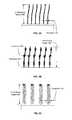
- FIG. 2Aillustrates an underframe including a vertically aligned array of nanotubes or nanowires, according to various embodiments of the invention.
- FIG. 2Billustrates an underframe including a vertically aligned array of nanotubes or nanowires, including diameter variation along the length of the nanotubes or nanowires, according to various embodiments of the invention.
- FIG. 2Cillustrates an underframe including a vertically aligned array of nanofibers, with ‘graphitic’ edges exposed, according to various embodiments of the invention.
- FIG. 2Dillustrates an underframe including a vertically aligned array of branched nanotubes, branched nanofibers, or branched nanowires, according to various embodiments of the invention.
- FIG. 2Eillustrates an underframe including a template formed aerogel, according to various embodiments of the invention.
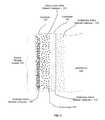
- FIG. 3illustrates further details of a cross section of a portion of the energy storage electrode of FIG. 1A , according to various embodiments of the invention.
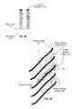
- FIG. 4Aillustrates a cross section of several elements of an energy storage electrode with stacked-cup nanofibers, according to various embodiments of the invention.
- FIG. 4Billustrates a cross section of several elements of a stacked-cup nanofiber with exposed ‘graphitic’ edges, according to various embodiments of the invention.
- FIG. 5Aillustrates a cross section of several elements of an energy storage electrode including a template formed aerogel, according to various embodiments of the invention.
- FIG. 5Billustrates a cross section of an aerogel, according to various embodiments of the invention.
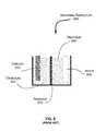
- FIG. 6illustrates a cross section of a prior art rechargeable battery.
- FIG. 7illustrates methods of producing an electrode, according to various embodiments of the invention.
- FIG. 1Aillustrates a cross section of a single element of an energy storage electrode 100 , according to various embodiments of the invention.
- One or more of electrode 100may be used in a rechargeable battery, such as the rechargeable (secondary) battery of FIG. 6 , in accordance with various embodiments of the invention.
- the electrode 100includes a substrate 110 , an optional seed layer 115 , and an energy storage system 190 .
- the energy storage system 190includes an underframe 130 and an active layer 150 .
- the seed layer 115may be used to initiate growth of the underframe 130 and may be used to facilitate connection of the energy storage system 190 to the substrate 110 .
- the energy storage system 190is coupled directly to the substrate 110 .
- the underframe 110supports the active layer 150 , as well as the optional overlayer 154 and optional underlayer 152 .
- the underframe 130provides enhanced surface area per unit volume for uptake and/or deposition of additional materials.
- the substrate 110can comprise graphite coated aluminum, graphite, Ni, Ag, Fe, Mg, Pb, W, Al, Hf, Mo, Pd, Ta, Au, In, Nb, Ti, Zr, Cu, Li, Ni, V, Zn, C, carbides of the above elements, silicides of the above elements, oxides of the above elements, nitrides of the above elements, an oxygen permeable membrane, and/or any combination thereof.
- the substratecan include one material, or a combination of more than one material. (The “above elements” refers to those discussed in this paragraph.)
- the substrate 110can be composed of both aluminum and an oxygen permeable membrane.
- the thickness of the substratecan range in thickness from approximately 5 microns to approximately 250 microns, 250 microns to 750 microns, 750 microns to 2 mm, and 2 mm to 5 mm, or any combination thereof, depending on the particular application of the secondary battery/cell 100 .
- the substrate 110includes gold, tin, silver, aluminum, copper, graphite, nickel, and/or the like.
- the substrate 110is a semi-conductor material.
- the semi-conductor materialincludes elemental materials such as silicon and germanium, or compound semiconductors such as gallium arsenide and indium phosphide, or alloys such as silicon germanium or aluminum gallium arsenide.
- the substrate 110includes an oxygen permeable membrane, polymers, porous materials such as aerogel, metal, a semiconductor, and/or an insulator.
- the substrate 110may be fabricated in a variety of shapes.
- the substrate 110may be planar (single sided and double sided), cylindrical, finned, and/or the like.
- the shape of substrate 110is selected so as to maximize available surface area.
- the electrode 100typically includes multiple energy storage systems 190 , optionally in an array.
- the optional seed layer 115serves one or more of a number of functions and may include several sub-layers.
- the seed layer 115may comprise an initial layer 117 , an intermediate layer 118 , and/or a final layer 119 .
- the seed layer 115may be configured to control the cross sectional area (e.g., diameter) of the underframe 130 by controlling an area in which initial growth of the underframe 130 occurs.
- the relative and/or absolute thicknesses of the initial layer 117 , an intermediate layer 118 , and/or a final layer 119can be selected to control the area of initial growth of the underframe 130 and thus the underframe cross sectional area (e.g., diameter) shown in FIGS. 2A, 2B, 2C, 2D , & 2 E).
- the seed layer 115may control adhesion of the underframe 130 to the substrate 110 .
- the spacing between adjacent underframe 130 and/or the cross section of the underframe 130may limit the possible thickness of the active layer 150 , over-layer 154 , underlayer 152 , and vice-versa.
- the seed layer 115includes Ti, Fe, Co, TiN, and/or Mo.
- the seed layer 115may control a density of initiation points and/or an areal density of growth initiation points for the underframe 130 .
- the density of initiation pointsdetermines the density of underframe 130 attachment points.
- the density of attachment pointsmay by between 10 3 /cm 2 to 10 11 /cm 2 , generally 10 7 /cm 2 to 10 10 /cm 2 .
- the initiation densitymay be expressed as a number of support filament initiation sites per unit area, e.g., number/cm 2 .
- the areal densityis the density of underframe 130 tips that are distal from seed layer 115 and substrate 110 .
- the areal densitycan be greater than the density of attachment points because the underframe 130 may be branched, as discussed further elsewhere herein.
- the areal densitymay be expressed as a number of support filament tips per unit area, e.g., number/cm 2 .
- the seed layer 115is a single material deposited on the substrate 110 in a single layer.
- the seed layer 115includes multiple (2, 3 or more) sub-layers of differing materials, e.g., initial layer 117 , intermediate layer 118 , and/or final layer 119 .
- Each of the sub-layers of the seed layer 115may be configured to perform various functions.
- one of the sub-layersmay include a barrier layer configured to prevent migration of atoms between layers; include an adhesion layer configured to bind two layers together; a protection layer configured to protect underlying or overlying layers from chemical/physical degradation; a conduction layer configured to provide conductivity; a stress/strain layer configured to act as a mechanical buffer between two layers; a binding/release layer configured to bind/release the final seed material to/from the underlying substrate; a layer configured to inhibit the growth of nanotube, nanofiber, nanowire, and/or aerogels, and/or a seed layer to initiate nanotube, nanofiber, nanowire, and/or aerogel growth.
- a barrier layerconfigured to prevent migration of atoms between layers
- FIG. 1Bis a cross section illustrating details of the seed layer 115 of FIG. 1A , according to various embodiments of the invention.
- the seed layer 115 illustrated in FIG. 1Bincludes a stack of sub-layers comprising different materials.
- the sub-layersinclude, for example, an initial layer 117 , an intermediate layer 118 and a final layer 119 .
- the initial layer 117is coupled to the substrate and forms a base for the intermediate layer 118 .
- the intermediate layer 118is deposited on the initial layer 117 and configured to form a base for the final layer 119 .
- the final layer 119is deposited on the intermediate layer 118 and is configured to provide sites for attachment and initiation of growth of the underframe 130 .
- the final layer 119is configured to inhibit the growth of a nanotube, nanofiber, nanowire, and/or aerogel.
- the final layer 119includes molybdenum, iron, cobalt, nickel, carbon, graphite, graphene, and/or the like.
- Various materials in the final layer 119may initiate or inhibit growth and/or provide for attachment of the including nanotube, nanofiber, nanowire, and/or aerogel.
- the intermediate layer 118may comprise, for example, iron, cobalt, nickel, titanium, titanium nitride, aluminum, and/or the like.
- the initial layer 117may include, for example, platinum, tungsten, titanium, chromium, and/or the like. It will be appreciated that alternative materials may be included in the sub-layers of seed layer 115 .
- the underframe 130includes nanotube, nanofiber, nanowire, and/or aerogel. More specifically, the nanotube, nanofiber, nanowire, and/or aerogel may comprise materials of metals, carbon, graphene, boron nitride, silicon, TiO 2 , copper, transition metals, oxides, nitrides, silicides, carbides, SiO 2 , silica, transition metal oxides, TiN, SiC, TiC, and/or any combination thereof.
- the nanotubes, nanofibers, nanowires, and/or aerogelmay be doped with materials, including, but not limited to boron, phosphor, and/or nitrogen.
- the underframe 130includes carbon nanotubes or fibers having a stacked-cup structure.
- underframe 130is in the form of a mesh and each of energy storage system 190 need not be attached to substrate 110 and/or seed layer 115 by an end.
- the stacked-cup structureprovides variable surface texture of the underframe 130 . This surface variation can result in useful variation and/or structure in any of the layers placed on the underframe 130 .
- the underframe 130provides a mechanical base for deposition and growth of the active layer 150 , underlayer 152 , and overlayer 154 .
- the underframe 130may also provide strength (e.g., tensile strength, compression strength, shear strength, and/or the like) to the active layer 150 .
- the additional strengthreduces or prevents damage to the energy storage system 190 during expansion and/or contraction of the active layer 150 .
- the nanotubesmay include a single wall or multiple walls.
- the nanofibersmay include a cup like stacking structure along it's length; the edges of these cups may be described as being ‘graphitic’ with respect to their material properties i.e. the edges act as graphene sheets.
- the nanotube, nanofiber, nanowire, and/or aerogel of the underframe 130is configured to act as an active material in which material is adsorbed and/or reactions catalyzed.
- the nanotube, nanofiber, nanowire, and/or aerogel of the underframe 130is configured to allow for uptake of additional material, such as gases (O 2 , CO 2 , CO, N 2 , NO 2 , NO, H2, etc.), nano-particles and/or thin films, such as gold, platinum, MnO x , CuFe, beta-MnO 2 /Pt, Pd, Ru, MoN/NGS, Li 5 FeO 4 , Li 2 MnO 3 *LiFeO 2 , FeO 4 , CoFe 2 O 4 , TiN, TiC, TiO 2 , graphite, Ni, Ag, Fe, Mg, Pb, W, Al, Hf, Mo, Pd, Ta, Au, In, Nb, Ti, Zr, Cu,
- gasesO 2 ,
- the active layer 150does coat some but not all of the length of the underframe 130 .
- a portion of the underframe 130forms an uncoated region 135 .
- the uncoated region 135is configured to provide a region for flex and motion of the underframe 130 . This flex can reduce mechanical stress resulting from expansion and contraction of the active layer 150 . If not reduced, this stress can cause breakage and/or separation of the underframe 130 from the seed layer 115 . Additionally, this uncoated region 135 may provide additional volume for gas, e.g., O 2 , capture and/or sequestration.
- silicon breakagesubstantially compromises adhesion of silicon to an anode, thus, decreasing longevity.
- Methodshave been suggested to improve the lifetime of silicon anodes, for example, growing silicon nano-wires on stainless steel.
- the length of the uncoated region 135may range from several angstroms to several microns. In some embodiments the length of the uncoated region 135 is selected such that the active layer 150 does not reach or only just reaches the seed layer 115 . In various embodiments the length of the uncoated region 135 is at least 0.1, 0.25, 0.3, 0.5, or 1.0 micrometers. In some embodiments, the length of the uncoated region 135 is substantially greater than a micron. In various embodiments the length of the uncoated region 135 is at least 20%, 30%, 40%, 55%, 70%, 85%, 90%, or 95% of the total length of the underframe 130 height.
- the uncoated region 135is typically located proximate to the end of underframe 130 closest to the seed layer 115 . However, uncoated region 135 may be provided at other or alternative parts of underframe 130 . For example, uncoated region 135 may be provided proximate to branches within underframe 130 .
- uncoated region 135is a region that has reduced coating of active layer 150 relative to other parts of energy storage system 190 , rather than a region having no coat at all.
- uncoated region 135may have a coating of active layer 150 whose thickness is less than 10, 25 or 50% of the thickness of the active layer 150 found in other regions of energy storage system 190 .
- FIG. 1Cis a cross section of a portion of the energy storage system 190 of FIG. 1A , according to various embodiments. An exemplary location of this cross section is shown by label “A” in FIG. 1A .
- energy storage system 190includes an optional underlayer 152 between the underframe 130 and the active layer 150 , and an optional overlayer 154 .
- Overlayer 154optionally encapsulates the active layer 150 , forming a barrier between active layer 150 and an electrolyte.
- the electrolyteincludes an active material configured to react in an electrochemical reaction at the cathode (a cathode active material).
- the cathode active materialmay include, for example, lithium ion or some other cation.
- the underlayer 152is configured to provide a seed layer for vapor-liquid-solid (VLS) growth of the active layer 150 .
- the underlayer 152includes a thin layer (e.g., less than one micrometer) of a metal or a series of metals (e.g., a transition metal, gold, silver, copper, nickel, and/or the like) or a salt (e.g., LiF).
- Underlayer 152optionally includes a silicide. Other materials may be used to form an underlayer 152 depending on the desired effect.
- the underlayer 152can be composed of a thin film or particulate layer with thicknesses that ranges from about 1 nm to 5 nm, 3 nm to 7 nm, 5 nm to 12 nm, 10 nm to 17 nm, 13 nm to 25 nm, 20 nm to 47 nm, 29 nm to 53 nm, 37 nm to 71 nm, 57 nm to 101 nm, or any combination thereof.
- This thin film or particulate layermay have a material composition comprising gold, platinum, MnO x , CuFe, beta-MnO 2 /Pt, Pd, Ru, MoN/NGS, Li 5 FeO 4 , Li 2 MnO 3 *LiFeO 2 , FeO 4 , CoFe 2 O 4 , TiN, TiC, TiO 2 , and/or any combination thereof.
- underlayer 152can be comprised of nanoparticles with average diameters of 1 nm, 3 nm, 5 nm, 8 nm, 13 nm, 17 nm, 23 nm, 29 nm, 37 nm, 43 nm, 53 nm, 61 nm, 67 nm, 79 nm, 97 nm, 115 nm, possibly larger, or any range there between. Underlayer 152 is optionally comprised of both thin films and nanoparticles.
- Underlayer 152can also be partially comprised of gel electrolyes, such as P(VDF-HFP)-based polymer electrolytes, poly acrylic acid, and polyfluorene-based conducting polymers, incorporating a carbon-oxygen functional group (carbonyl).
- the thickness of the underlayer 152can be as much as 500 nm, 750 nm, 900 nm, 1200 nm, or possibly more.
- the overlayer 154may be grown and/or deposited on the active layer 150 .
- the over-layer 154may partially or fully encapsulate the active layer 150 .
- the materials that comprise the over-layer 154include, for example, metals such as gold, silver, copper, and/or the like.
- the over-layer 154can also include a diamond-like coating (DLC), or an insulator, such as SiO 2 , a binder, a polymer, and/or the like.
- the thickness of the over-layer 154is typically less than one micrometer in the case of metals, semiconductors or insulators. In various embodiments, the thickness of the over-layer 154 may be larger than a micrometer for a binder or larger for polymers.
- the over-layer 154can be composed of a thin film with thicknesses that range from about 1 nm to 5 nm, 3 nm to 7 nm, 5 nm to 12 nm, 10 nm to 17 nm, 13 nm to 25 nm, 20 nm to 47 nm, 29 nm to 53 nm, 37 nm to 71 nm, 57 nm to 101 nm, or an combination thereof.
- This thin filmmay have a material composition comprising of gold, platinum, MnO x , CuFe, beta-MnO 2 /Pt, Pd, Ru, MoN/NGS, Li 5 FeO 4 , Li 2 MnO 3 *LiFeO 2 , FeO 4 , CoFe 2 O 4 , TiN, TiC, TiO 2 , and/or any combination thereof.
- overlayer 154can be comprised of nanoparticles with average diameters of up to 1 nm, 3 nm, 5 nm, 8 nm, 13 nm, 17 nm, 23 nm, 29 nm, 37 nm, 43 nm, 53 nm, 61 nm, 67 nm, 79 nm, 97 nm, 115 nm, possibly larger, or any range there between.
- These particlesmay have a material composition comprising gold, platinum, MnO x , CuFe, beta-MnO 2 /Pt, Pd, Ru, MoN/NGS, Li 5 FeO 4 , Li 2 MnO 3 *LiFeO 2 , FeO 4 , CoFe 2 O 4 , TiN, TiC, TiO 2 , and/or any combination thereof.
- Overlayer 154is optionally comprised of both thin films and nanoparticles.
- Overlayer 154can also be partially comprised of gel electrolyes, such as P(VDF-HFP)-based polymer electrolytes, poly acrylic acid, and polyfluorene-based conducting polymers, incorporating a carbon-oxygen functional group (carbonyl).
- the thickness of the overlayer 154can be up to 500 nm, 750 nm, 900 nm, 1200 nm, or possibly more.
- the active layer 150may be grown/deposited on the underframe 130 using a various methods. These methods include, for example, evaporation, sputtering, PECVD (Plasma-Enhanced Chemical Vapor Deposition), low-pressure chemical vapor deposition (LPCVD), VLS (Vapor Liquid Solid synthesis), electroplating, electro-less deposition, “field-free” chemical vapor deposition (CVD), metal-organic CVD, molecular beam epitaxy (MBE), and/or the like. In some embodiments, the active layer 150 distribution over the surface of the underframe 130 is uniform. Alternatively, the active layer 150 thickness is not uniform over the length of the underframe 130 .
- the uncoated region 135 heightmay vary from 0% to 99% of the height of the underframe 130 .
- the active layer 150 proximate to the substrate 110has a smaller thickness relative to the distal end of the underframe 130 . As such, the thickness of the active layer 150 may increase, along underframe 130 , with distance from the substrate 110 .
- the thickness of the active layeris from 1-10 nm, 5-50 nm, 15-75 nm, 25-100 nm, 50-200 nm, 80-350 nm, 120-600 nm, 175-950 nm, 250-1500 nm, 425-2500 nm, 725-4000 nm, any combination thereof, or possibly larger.
- Nanoparticlesare optionally interspersed within the active layer 150 . These nanoparticles are comprised of, for example, gold, platinum, MnO x , CuFe, beta-MnO 2 /Pt, Pd, Ru, MoN/NGS, Li 5 FeO 4 , Li 2 MnO 3 *LiFeO 2 , FeO 4 , CoFe 2 O 4 , TiN, TiC, TiO 2 , or any combination thereof.
- These nanoparticlesmay have diameters between 1 nm, 3 nm, 5 nm, 8 nm, 13 nm, 17 nm, 23 nm, 29 nm, 37 nm, 43 nm, 53 nm, 61 nm, 67 nm, 79 nm, 97 nm, 115 nm, possibly larger, or any combination thereof.
- the active layer 150may be partially comprised of gel electrolyes, such as P(VDF-HFP)-based polymer electrolytes, poly acrylic acid, and polyfluorene-based conducting polymers, incorporating a carbon-oxygen functional group (carbonyl).
- a number of methodsmay be employed to achieve a desired length for the uncoated region 135 .
- Examples of such methodsinclude controlling the aspect ratio of the underframe 130 during growth, directional deposition, electro-deposition, electro-less deposition at the bottom layer to isolate the trunk, sputter and light etch of a masking layer to open the underframe 130 to active layer 150 growth/deposition, pre-coupling layer isolation (i.e. mask seed locations) prior to growth of the underframe 130 , modifying growth parameters of the underframe 130 to achieve an advantageous aspect ratio (such as a tree like structure), or performing a deposition and directional etch back to free the under-frame 130 from coverage by active layer 150 .
- FIGS. 2A-2Eillustrate various examples of individual nanotubes, nanofibers, nanowires and aerogel in an array.
- the arrayis optionally a vertically aligned array.
- the individual nanotubes, nanofibers, nanowires and aerogelare shown without the overlaying active layer 150 etc. that is included on these elements to form Energy Storage System 190 , as illustrated in FIGS. 1A-1C .
- the term underframeis used to refer to a single structural element (e.g., a signal support filament including a nanotube, nanofiber, nanowire, or aerogel) and also to an array thereof.
- underframe 130includes a mixture of nanotubes, nanowires and/or aerogel.
- FIG. 2Aillustrates an underframe 130 of vertically aligned arrays of nanotubes or nanowires.
- the diameter 210 of an individual nanotube, nanofiber, or nanowireis less than 10 nm, between 10 nm and 50 nm, between 20 nm and 80 nm, between 40 nm and 120 nm, between 80 nm and 300 nm, between 120 nm and 450 nm, between 255 and 710 nm, between 380 nm and 1050 nm, and greater the 900 nm, or any combination thereof.
- the diameter 210can vary along the length (height) of the an individual nanotube, nanofiber, or nanowire.
- the diameters of the individual nanotubes, nanofibers, or nanowiresneed not be the same for all elements of the vertically aligned array.
- the variation in diameterscan be up to 0.1%, 0.25%, 2%, 5%, 10%, 25%, or possibly greater.
- the underframe height 290 of the arrayis an average height and is about 1 micron to 5 microns, 2 microns to 10 microns, 4 microns to 20 microns, 7 microns to 31 microns, 17 microns to 57 microns, 31 microns to 123 microns, 43 microns to 253 microns, 79 microns to 623 microns, 258 microns to 1289 microns, possibly larger, or any combination thereof.
- This heightmay vary as the array of nanotubes, nanofibers, or nanowires tilts or bends. Height variation of the individual nanotubes, nanofibers, or nanowires may also be present.
- FIG. 2Billustrates an underframe 130 of vertically aligned arrays of nanotubes, nanofibers, or nanowires, with diameter variation along the length of the nanotube, nanofibers, or nanowire.
- the diameter 225is less than 10 nm, between 10 nm and 50 nm, between 20 nm and 80 nm, between 40 nm and 120 nm, between 80 nm and 300 nm, between 120 nm and 450 nm, between 255 and 710 nm, between 380 nm and 1050 nm, and greater the 900 nm, or any combination thereof.
- the diameter 225can vary along the length (height) of the individual nanotube, nanofiber, or nanowire.
- the diameters of the individual nanotubes, nanofibers, or nanowiresneed not be the same for all elements of the vertically aligned array.
- the variation in diameterscan be up to 0.1%, 0.25%, 2%, 5%, 10%, 25%, or possibly greater.
- the diameter 220can vary as different cross-sectional shapes, such as a oval, tear drop, rectangle, diamond, or trapezoid. Other cross sectional shapes are possible.
- the diameter 220varies as a result of a stacked-cup structure of individual nanotubes, nanofibers, or nanowires. This structure is discussed further elsewhere herein.
- FIG. 2Cillustrates an under-frame 130 of vertically aligned arrays of nanofibers, with ‘graphitic’ edges exposed. This occurs in, for example, the stacked-cup structure of some carbon nanofibers.
- the diameter 230is less than 10 nm, between 10 nm and 50 nm, between 20 nm and 80 nm, between 40 nm and 120 nm, between 80 nm and 300 nm, between 120 nm and 450 nm, between 255 and 710 nm, between 380 nm and 1050 nm, greater the 900 nm, or any combination thereof.
- the diameter 230can vary along the length (height) of an individual nanotube, nanofiber, or nanowire.
- the diameters of the individual nanotube, nanofiber, or nanowireneed not be the same for all elements of the vertically aligned array.
- the variation in diameters 230can be up to 0.1%, 0.25%, 2%, 5%, 10%, 25%, or possibly greater.
- FIG. 2Dillustrates an under-frame 130 of vertically aligned arrays of nanotubes, nanofibers, or nanowires including branches.
- the diameter 240 and underframe height 290include characteristics and ranges similar to those discussed above with respect to FIGS. 2A-2C (e.g., diameter 210 , diameter 225 , and diameter 230 ).
- FIG. 2Eillustrates an under-frame 130 of template formed aerogel.
- the aerogelcan be a continuous layer or in an array as illustrated. In some embodiments, the aerogel is formed without the use of a template. In some embodiments the aerogel is mixed with the nanotube, nanofiber, or nanowire structures illustrated in FIGS. 2A-2D . In these embodiments the aerogel can be disposed in an array between the individual nanotubes, nanofibers, or nanowires, or may be deposited on the an individual nanotubes, nanofibers, or nanowires.
- the template aerogel diameter 250is less than 10 nm, between 10 nm and 50 nm, between 20 nm and 80 nm, between 40 nm and 120 nm, between 80 nm and 300 nm, between 120 nm and 450 nm, between 255 and 710 nm, between 380 nm and 1050 nm, 510 nm and 2300 nm, 1550 nm and 4700 nm, 3380 nm and 7450 nm, 6680 nm and 15500 nm, 9870 nm and 23500 nm, and greater the 50000 nm.
- the template aerogel diameter 250can vary along the length (height) of the aerogel and/or between members of the array. The variation in diameters can be up to 0.1%, 0.25%, 2%, 5%, 10%, 25%, or possibly greater.
- FIG. 3illustrates further details of a cross section of a portion, illustrated in FIG. 1C , of the energy storage system 190 , according to various embodiments of the invention.
- These embodimentsinclude active material catalyzers 310 (AMC).
- Active material catalyzers 310are an example of surface effect dominant sites but optionally or alternatively serve to catalyze electrical chemical reactions.
- Surface effect dominant sitesinclude surfaces of a nanoparticle configured to adsorb charge carriers in a faradaic interaction, e.g., to undergo redox reactions with charge carriers. They are referred to as “surface effect dominant” because optionally, for these nanoparticles, the faradaic interaction between the charge carriers and the nanoparticle surfaces dominate bulk faradaic interactions.
- the charge carriersmay be more likely to react at the surface relative to the bulk of the nanoparticles.
- a lithium ioncould more likely adsorb onto the surface of the nanoparticle rather than being absorbed or plate into the bulk of the nanoparticle.
- These nanoparticlesare sometimes referred to as surface redox particles.
- the faradaic interactionresults in a pseudo capacitor that can store a significant amount of loosely bound charge and thus provide a significant power density to an energy storage device.
- pseudo capacitancean electron is exchanged (e.g., donated). In this case between the charge carrier to the nanoparticle.
- a faradaic interactionis an interaction in which a charge is transferred (e.g., donated) as a result of an electrochemical interaction.
- AMCs 310are not surface effect dominant sites in some embodiments.
- active material catalyzers 310are typically more than just surface effect dominant sites.
- active material catalyzers 310are configured to catalyze electro-chemical reactions.
- active material catalyzers 310are configured to release oxygen from a compound including lithium and oxygen.
- the catalyzers 310are configured to catalyze Li + +1 ⁇ 2O 2 +e ⁇ ⁇ 1 ⁇ 2Li 2 O 2 and/or Li + +1 ⁇ 4O 2 +e ⁇ ⁇ 1 ⁇ 2Li 2 O, or any other reactions known in the art of lithium based batteries.
- the interactions that occur at active material catalyzers 310may be dependent on the potentials applied.
- Active material catalyzers 310can be implemented as nanoparticles and/or thin films. Active materials catalyzers 310 are generally comprised of materials such as gold, platinum, MnO x , CuFe, beta-MnO 2 /Pt, Pd, Ru, MoN/NGS, Li 5 FeO 4 , Li 2 MnO 3 *LiFeO 2 , FeO 4 , CoFe 2 O 4 , TiN, TiC, TiO 2 , and/or any combination thereof.
- active material catalyzers 310can have average diameters of up to 1 nm, 3 nm, 5 nm, 8 nm, 13 nm, 17 nm, 23 nm, 29 nm, 37 nm, 43 nm, 53 nm, 61 nm, 67 nm, 79 nm, 97 nm, 115 nm, possibly larger, and/or any combination thereof.
- the nanoparticlescan have multiple sizes, therefore implying a distribution of particle size. This distribution is not necessarily a normal distribution, e.g., the distribution may be bimodal.
- These nanoparticlescan be found as part of the underframe 130 , underlayer 152 , active layer 150 , and/or overlayer 154 .
- Thin film AMCs 310have an average thickness range from about 1 nm to 5 nm, 3 nm to 7 nm, 5 nm to 12 nm, 10 nm to 17 nm, 13 nm to 25 nm, 20 nm to 47 nm, 29 nm to 53 nm, 37 nm to 71 nm, 57 nm to 101 nm, possibly larger, or any combination thereof.
- Thin film AMCs 310can be part of the underlayer 152 and/or the overlayer 154 .
- the thickness of the active layeris from 1-10 nm, 5-50 nm, 15-75 nm, 25-100 nm, 50-200 nm, 80-350 nm, 120-600 nm, 175-950 nm, 250-1500 nm, 425-2500 nm, 725-4000 nm, larger, or any combination thereof.
- AMCs 310are concentrated at one or the other edge of any of the layers, and/or may be concentrated at a boundary between any two of the layers illustrated.
- AMCs 310are concentrated around the boundary between Overlayer 154 and Active Layer 150 , and/or at the boundary between Active Layer 150 and Underlayer 152 .
- concentrationscan be achieved, for example, by depositing the AMCs between steps of generating any two of the illustrated layers and/or underframe 130 .
- AMCs 310may be disposed as a gradient within any of the layers illustrated.
- AMCs 310include oxygen adsorbing materials.
- FIG. 4Aillustrates a cross section of several elements of an energy storage electrode with stacked-cup nanofibers, according to various embodiments of the invention.
- stacked-cup nanofibershave exposed graphitic edges and planes that act as graphene sheets. These graphene sheets wrap around a central ‘core’. These sheets layer on top of each other, creating increased surface area relative to standard nanotubes (which typically have a smooth surface). Additionally, the stacked sheets create channels to the central core of the cupped nanofiber 410 .
- These stacked-cup nanofiberscan be in a vertically aligned array as illustrated in FIG. 2C or separated from the surface on which they were grown and attached as a mesh to a new substrate using a binder. Further examples of the stacked-cup structure are illustrated in FIGS. 3A-3C and 4 of U.S. patent application Ser. No. 13/935,334 filed Jul. 3, 2013.
- FIG. 4Billustrates a detailed cross section of several elements (“cup edges”) of a stacked-cup nanofiber with exposed ‘graphitic’ edges, according to various embodiments of the invention.
- the exposed graphitic edge sheetsallow for incursion of particulate active material catalyzer 310 including the materials and characteristics discussed elsewhere herein, between the graphitic edges. See region “A” in FIG. 4B .
- an element of energy storage system 190can be created, with all the attributes as listed and shown in FIG. 3 , on each exposed graphite edge of stacked-cup nanofiber. See region “B” in FIG. 4B .
- An additional attribute of the stacked-cup nanofiber structureis the existence of a gas storage channel for gas sequestration. See region “C” in FIG. 4B .
- This channeloptionally provides a path for gasses to reach a hollow central core within the nanofiber.
- gassescan include O 2 , CO 2 , CO, N 2 , NO 2 , NO, H 2 , etc.
- an oxygen absorbersuch as strontium cobaltite, is included in the channel 440 between the exposed (graphene like) stacked-cup edges to capture excess oxygen.
- Other materialscan optionally be used to capture and release other gases.
- Absorbers of the above gassesmay also be included within the hollow central core 450 of a stacked-cup nanofiber or an unzipped nanotube.
- regions “A,” “B” and “C” of FIG. 4may be including in stacked-cup nanofibers in any combination.
- one embodimentincludes the particulate active material catalyzer 310 illustrated in region “A,” the active layer 150 included in region “B,” and room for oxygen sequestration illustrated in region “C.” These are optionally included within the same channel 440 .
- FIG. 5Aillustrates a cross section of several elements of an energy storage electrode including a template formed aerogel, according to various embodiments of the invention.
- the aerogelhas an average density that ranges from about 0.008 g/cm 3 to 0.3 g/cm 3 , a surface area that ranges from about 200 m 2 /g to 2000 m 2 /g, a pore volume that ranges from about 0.5 cm 3 /g to 25 cm 3 /g, and an average pore diameter that ranges from about 2 nm to 50 nm.
- FIG. 5Billustrates a cross section of an aerogel 510 , according to various embodiments of the invention.
- exposed aerogel pores 520 and resulting large surface areaallow for incursion of active material catalyzer 310 within the aerogel.
- An exampleis illustrated in region “A” of FIG. 5B .
- an energy storage system 190(with or without active material catalyzer 310 ) can be created on surfaces of the aerogel. These embodiments of energy storage system 190 can include any or all the attributes and characteristics discussed elsewhere herein.
- An example of energy storage system 190is illustrated in region “A” of FIG. 5B . This example can be included on any or all of the available surfaces of the aerogel 510 . The surfaces and boundaries between the pores function as the underframe 130 .
- the active material catalyzer 310 shown in region “A” and the energy storage system 190 shown in region “B”are optionally found together, e.g., the active material catalyzer 310 can be included in the energy storage system 190 as discussed elsewhere herein.
- An additional attribute of the aerogelis the presence of a gas storage channels for gas sequestration.
- gasescan be O 2 , CO 2 , CO, N 2 , NO 2 , NO, H2, etc.
- gasescan be O 2 , CO 2 , CO, N 2 , NO 2 , NO, H2, etc.
- an oxygen absorbersuch as strontium cobaltite
- Other materialscan optionally be used to capture and release other gases.
- the embodiments described in relation to FIG. 5Bmay be applied to a continuous aerogel (not shown).
- nanofibersare grown on an aerogel substrate (which in turn is on a more solid substrate 110 ).
- the aerogel substratemay include an oxygen absorber and the nanofibers may support the energy storage system 190 as discussed herein.
- FIG. 6illustrates a cross section of a prior art rechargeable battery (e.g., a secondary battery/cell 600 ).
- This batteryincludes a cathode 610 , an anode 620 , a separator 630 and an electrolyte 640 .
- the various embodiments illustrated in FIGS. 1-5 and discussed hereinmay be applied to either the cathode 610 or anode 620 .
- the secondary battery/cell 600may take many geometric forms and shapes as would be apparent to one of ordinary skill in the art.
- the cathode 610may be open to the atmosphere or sealed from the atmosphere.
- FIG. 7illustrates a method for fabricating an electrode including an energy storage system 190 including an underframe 130 .
- the first step 701is to receive a substrate 110 .
- Substrate 110is optionally graphite coated aluminum, graphite, Ni, Ag, Fe, Mg, Pb, W, Al, Hf, Mo, Pd, Ta, Au, In, Nb, Ti, Zr, Cu, Li, Ni, V, Zn, C, carbides of previously noted materials, silicides of previously noted materials, oxides of previously noted materials, nitrides of previously noted materials, an oxygen permeable membrane, or any combination thereof.
- the substrate 110can include one material, or a combination of several materials.
- the substrate 110can be of other materials, depending on the desired application. For instance, aerogel, stainless steel or graphite can be used for a substrate. Those skilled in the art of battery design can further specify other materials, depending on the desired application.
- substrate 110is flexible and configured to be coiled.
- An optional second step 703is to clean the substrate 110 .
- the purpose of cleaning 703 the substrate 110is to prepare the substrate 110 for the subsequent depositions and growth of materials in later process steps. It is meant to remove any undesired organics, oxides, and other contaminates present on the substrate 110 .
- the methods to clean the substrate 110can range from physical (using an abrasive, for instance, to remove a thin layer of material that has been exposed to contaminants), to chemical (using a solvent, such as acetone, iso-propanol, TCE, or methanol) and/or chemical etch (citric acid soak/rinse, which dissolves part of the actual substrate, in the case of copper), or any combination of physical and chemical methods to appropriately prepare the surface 110 for subsequent process steps.
- a third step 705is an optional seed layer deposition.
- Seed layer deposition 705is the process step where the base layer, or seed layer 115 , for underframe 130 growth is created. This process step can be implemented through a gas phase (physical or chemical) deposition/growth, a liquid phase deposition/growth, or a solid phase deposition/growth, or any combination thereof.
- Physical gas phase deposition techniques(where the material to be deposited is transported from the source to the substrate in the gas phase) can include: thermal evaporation, electron beam evaporation, DC sputtering, DC magnetron sputtering, RF sputtering, pulsed laser deposition, cathode arc deposition, and/or the like. It is also possible to use reactive physical vapor deposition, a method by which a ‘contaminate gas’ is injected into the chamber during the growth process, thereby incorporating itself into the layer as it grows.
- Chemical gas phase deposition techniques(where chemical precursors are transported to the surface in the gas phase, and then subsequently undergo a chemical reaction at the surface) can include Low Pressure Chemical Vapor Deposition, Plasma-Enhanced Chemical Vapor Deposition, Atmospheric Pressure Chemical Vapor Deposition, Metal-Organic Chemical Vapor Deposition, Hot-wire Chemical Vapor Deposition, Very High Frequency Plasma Enhanced Chemical Vapor Deposition, Microwave Plasma Enhanced Chemical Vapor Deposition, and/or the like.
- Liquid phase deposition techniques to create the seed layer 115can include plating, electroplating, or chemical solution deposition, etc.
- Solid phase deposition techniquescan include focused ion beam deposition.
- Another possibility for depositionis a solution that contains a liquid and a suspension of appropriate sized particles that are sprayed onto the current collector, and then the substrate is subsequently ‘cured’ such that the carrier solution is removed, leaving the particles intact on the surface of the substrate.
- Any combination of the above process stepscan be used to create an appropriate seed layer 115 for creating the initiation sites for the underframe 130 growth.
- a forth step 715 in the processis the creation of the initiation sites, defined as the location where the underframe 130 starts growth on the seed layer 115 .
- This stepis dependent on methods chosen to create the seed layer 115 .
- the initiation sites separation distancecan be determined by the thickness and materials chosen for seed layer deposition 705 .
- a seed layer of 3000 angstroms nickel/300 angstroms chromewill produce a certain number of initiation sites per square centimeter. If the thickness of the nickel is reduced to 2000 angstroms, the number of initiation sites per square centimeter will be different than that for a thickness of 3000 angstroms nickel. If another material is chosen, such as iron to replace nickel, the resultant initiation sites per square centimeter will also be different.
- Step 715is optionally part of step 705 .
- a solid phase deposition techniquecan allow for control of the initiation sites per square centimeter.
- Thiscan be a focused ion beam deposition, where the initiation sites/cm 2 are directly controlled by the by where the focused ion beam deposits it material, or a nano-particle suspension, where the initiation sites/cm 2 is controlled by the number of nano-particles contained in a given suspension volume.
- the number of initiation sitescan also be controlled by the size of the focused ion beam deposition site, or the size of the nano-particles in solution, etc.
- the initiation sitesare typically created when a reactor in which the electrode is produced reaches the appropriate reaction temperature with the appropriate feedstock gases flowing, and the feedstock gas begins to catalyze with the seed layer 115 .
- the initiation siteshave thus been created, and the underframe 130 growth has commenced.
- a fifth step 720is to grow the underframe 130 .
- growth processesavailable to grow the underframe 130 .
- chemical Vapor Deposition, Thermal Chemical Vapor Deposition, Vapor-Liquid-Solid growth (a type of CVD), and Plasma Enhanced Chemical Vapor Depositionare processes by which Nano-Tube (NT), Nano-Fiber (NF), and Nano-Wire (NW) growth has been achieved.
- NTNano-Tube
- NFNano-Fiber
- NWNano-Wire
- feedstock gasesthat can be used to grow NT/NF are carbon monoxide, methane, ethane, ethylene, acetylene, and/or the like. It is also possible to use other hydrocarbons or inorganic compounds for the growth process.
- Plasma Enhanced Chemical Vapor Deposition(CVD) method, due to the fact that the growth of the support filament 110 aligns with the electric field of the plasma, thus allowing for the production of vertically aligned underframe 130 .
- Thermal CVDunder certain process conditions, can also produce vertically aligned underframe 130 units.
- Water-Assisted CVDmakes possible very high aspect ratio vertically aligned underframe 130 (length vs. diameter roughly equal to 1,000,000), allowing for very tall underframe 130 .
- bacteria/virusescan be used to grow the NT/NF/NW in the presence of an applied electric field, producing vertically aligned support filaments.
- Another method of underframe 130 growthis to apply an electric and/or magnetic field during VLS growth to control the trajectory of the growing NT/NF/NW, this controlling the three dimensional shape of the underframe 130 .
- Another techniqueis to begin growth of the NT/NF/NW underframe 130 with the reactor operating in PECVD mode; after a specified time, the reactor can be converted to Thermal CVD mode; and then again, after a specified time, the reactor is converted back to PECVD mode.
- the underframe height 290 of the underframe 130is generally determined by the duration of the growth process.
- the temperature of the reactor, the feedstock gases used, and the combination and strength of applied electric and magnetic fields (or the absence thereof)can influence the speed and amount of filament growth.
- the diameter 210 of the underframe 130is generally determined by the thickness of the seed layer 115 , or the size of the nano-particles contained in suspension, if a nano-particle suspension method is chosen to create the seed layer 115 , or the size of the ion beam, if focused ion beam deposition is chosen to create the seed layer 115 .
- the temperature of the reactor, the feedstock gases used, and the combination and strength of applied electric and magnetic fields (or the absence thereof)can influence diameter of the underframe 130 as well. This also applies to diameters 225 , 230 , and 240 .
- a sub-step 720 awhere the diameter and number of branches can be affected. This can be accomplished by changing temperature of the reactor, the feedstock gases used and their relative compositions and flow rates, direction and strength of applied electric and magnetic fields (or the absence thereof). The duration of the change implicitly determines the diameters 210 225 , 230 and 240 ), as well as the amount of branching, as shown in FIG. 2D .
- a sub-step 720 bwhere the diameter and number of branches can be affected. This can be accomplished by changing temperature of the reactor, the feedstock gases used and their relative compositions and flow rates, direction and strength of applied electric and magnetic fields (or the absence thereof). The duration of the change implicitly determines the NT/NF diameter 210 (as well as the other diameters 225 , 230 , and 240 ), as well as the amount of branching, as shown in FIG. 2D .
- the diameter, thickness, height, and branches of underframe 130are largely controlled by the changes in the aforementioned parameters; this can be done on a somewhat continuous basis by changing the input parameters for growth, creating the equivalent sub-steps 720 c , 720 d , etc., until it is decided to terminate growth.
- the growth processrequires the preparation and setting of a gel on the optional seed layer 115 .
- the gelis exchanged into 200 proof ethanol (or acetone) about four times over the course of a week. After one week, supercritically dry the gel.
- the template sizecan be defined by mechanically masking the locations where the aerogel is desired.
- the size of the aerogel templatecan be defined by photolithography.
- the thickness of the aerogel templatecan be defined by the thickness of the originally deposited gel on the seed layer 115 /substrate 110 .
- the eighth process step 730is deposit/grow the energy storage system 190 .
- the growth/deposition of the energy storage system 190can be implemented through a gas phase (physical or chemical) deposition/growth, a liquid phase deposition/growth, or a solid phase deposition/growth, or any combination thereof.
- Physical gas phase deposition techniques(where the material to be deposited is transported from the source to the substrate in the gas phase) can include: thermal evaporation, electron beam evaporation, DC sputtering, DC magnetron sputtering, RF sputtering, pulsed laser deposition, cathode arc deposition, and/or the like. It is also possible to use reactive physical vapor deposition, a method by which a ‘contaminate gas’ is injected into the chamber during the growth process, thereby incorporating itself into the layer as it grows.
- Chemical gas phase deposition techniques(where chemical precursors are transported to the surface in the gas phase, and then subsequently undergo a chemical reaction at the surface) can include Low Pressure Chemical Vapor Deposition, Plasma-Enhanced Chemical Vapor Deposition, Atmospheric Pressure Chemical Vapor Deposition, Metal-Organic Chemical Vapor Deposition, Hot-wire Chemical Vapor Deposition, Very High Frequency Plasma Enhanced Chemical Vapor Deposition, Microwave Plasma Enhanced Chemical Vapor Deposition, and/or the like.
- any deposition stagemore than one material can be deposited at a time.
- two (or more) different types of metalcan be deposited/grown at the same time, such as tin (Sn) and gold (Au);
- two (or more) different types of semiconductorcan be deposited/grown, such as silicon (Si) and germanium (Ge);
- two (or more) different types of oxidemay be grown/deposited, such as lithium iron phosphate (LiFePO 4 ) and lithium nickel cobalt manganese (Li(NiCoMn)O 2 ).
- material typessuch as a metal and a semiconductor, or a semiconductor and an oxide, or a metal and an oxide, or a metal, semiconductor, and oxide.
- Examplesinclude silicon (Si) and lithium (Li) co-depositions, silicon (Si) and LiO 2 (or SiO 2 ) co-depositions, and silicon (Si), lithium (Li), and LiO 2 (or SiO 2 ) co-depositions. It may be desirable to co-deposit insulating material as well, such as silicon dioxide (SiO 2 ), or silicon nitride (Si 3 N 4 ). Additionally, it may be desirable to co-deposit carbon (C) as well.
- depositing of active materialscan optionally be performed simultaneously with catalyst materials (such as gold, platinum, MnO x , CuFe, beta-MnO 2 /Pt, Pd, Ru, MoN/NGS, Li 5 FeO 4 , Li 2 MnO 3 *LiFeO 2 , FeO 4 , CoFe 2 O 4 , TiN, TiC, TiO 2 , or any combination thereof).
- catalyst materialssuch as gold, platinum, MnO x , CuFe, beta-MnO 2 /Pt, Pd, Ru, MoN/NGS, Li 5 FeO 4 , Li 2 MnO 3 *LiFeO 2 , FeO 4 , CoFe 2 O 4
- active materialssuch as Li 2 O 2 , Li 2 O, lithiated Ti
- the solventis driven out of the matrix, leaving only the binder and active/and/or catalyst material, thus creating an electrode including underframe 130 and energy storage system 190 .
- This techniquecan be applied to both an anode and cathode, with appropriate choice of materials.
- the reactivity of the energy storage system 190is controlled by appropriately choosing the deposition and growth technique. For instance, it is possible include catalyst materials during the deposition process of the active layer 150 .
- the deposited/grown energy storage systemis encapsulated.
- This encapsulationcould be gel electrolyes, such as P(VDF-HFP)-based polymer electrolytes, poly acrylic acid, and polyfluorene-based conducting polymers, incorporating a carbon-oxygen functional group (carbonyl).
- the electrode fabricationmay be complete.
- the electrodeis optionally included within a battery.
- nanofibersis meant to include nano-ribbon, nano-filaments, unzipped nanotubes, nanowires and/or nanotubes.
- energy storage systems 190are optionally formed on both sides of Substrate 110 .
- the teachings disclosed hereinmay be applied to both batteries and hybrid battery/capacitors.
- material catalyzer 310migrates from one layer to another during operation.
- the particles discussed hereinare multi-layered or hollow particles.
Landscapes
- Chemical & Material Sciences (AREA)
- Chemical Kinetics & Catalysis (AREA)
- Electrochemistry (AREA)
- General Chemical & Material Sciences (AREA)
- Engineering & Computer Science (AREA)
- Manufacturing & Machinery (AREA)
- Battery Electrode And Active Subsutance (AREA)
- Secondary Cells (AREA)
Abstract
Description
this application is a continuation-in-part of PCT/US14/11556 filed Jan. 14, 2014.
Claims (20)
Priority Applications (8)
| Application Number | Priority Date | Filing Date | Title |
|---|---|---|---|
| US14/176,137US9705136B2 (en) | 2008-02-25 | 2014-02-09 | High capacity energy storage |
| US14/625,372US10193142B2 (en) | 2008-02-25 | 2015-02-18 | Lithium-ion battery anode including preloaded lithium |
| US15/096,094US10205166B2 (en) | 2008-02-25 | 2016-04-11 | Energy storage devices including stabilized silicon |
| US15/645,432US20170309920A1 (en) | 2008-02-25 | 2017-07-10 | High Capacity Energy Storage |
| US15/645,401US20170309919A1 (en) | 2008-02-25 | 2017-07-10 | High Capacity Energy Storage |
| US16/227,962US10964938B2 (en) | 2008-02-25 | 2018-12-20 | Lithium-ion battery anode including preloaded lithium |
| US16/229,388US11075378B2 (en) | 2008-02-25 | 2018-12-21 | Energy storage devices including stabilized silicon |
| US17/153,192US11502292B2 (en) | 2008-02-25 | 2021-01-20 | Lithium-ion battery anode including preloaded lithium |
Applications Claiming Priority (21)
| Application Number | Priority Date | Filing Date | Title |
|---|---|---|---|
| US6701808P | 2008-02-25 | 2008-02-25 | |
| US13067908P | 2008-06-02 | 2008-06-02 | |
| US12/392,525US8420258B2 (en) | 2008-02-25 | 2009-02-25 | High capacity electrodes |
| US25409009P | 2009-10-22 | 2009-10-22 | |
| US12/904,113US8481214B2 (en) | 2008-02-25 | 2010-10-13 | Electrodes including support filament with collar stop |
| US201161578545P | 2011-12-21 | 2011-12-21 | |
| US201261603833P | 2012-02-27 | 2012-02-27 | |
| US201261615179P | 2012-03-23 | 2012-03-23 | |
| US201261667876P | 2012-07-03 | 2012-07-03 | |
| US201261677317P | 2012-07-30 | 2012-07-30 | |
| US13/725,969US9412998B2 (en) | 2009-02-25 | 2012-12-21 | Energy storage devices |
| US201361752437P | 2013-01-14 | 2013-01-14 | |
| US13/779,409US9349544B2 (en) | 2009-02-25 | 2013-02-27 | Hybrid energy storage devices including support filaments |
| US201361806819P | 2013-03-29 | 2013-03-29 | |
| US13/868,957US20160301067A9 (en) | 2008-02-25 | 2013-04-23 | Hybrid Energy Storage Devices |
| US13/935,334US9362549B2 (en) | 2011-12-21 | 2013-07-03 | Lithium-ion battery anode including core-shell heterostructure of silicon coated vertically aligned carbon nanofibers |
| US201361868002P | 2013-08-20 | 2013-08-20 | |
| US201361887447P | 2013-10-07 | 2013-10-07 | |
| US201361904417P | 2013-11-14 | 2013-11-14 | |
| US201361910955P | 2013-12-02 | 2013-12-02 | |
| US14/176,137US9705136B2 (en) | 2008-02-25 | 2014-02-09 | High capacity energy storage |
Related Parent Applications (5)
| Application Number | Title | Priority Date | Filing Date |
|---|---|---|---|
| US13/725,969Continuation-In-PartUS9412998B2 (en) | 2008-02-25 | 2012-12-21 | Energy storage devices |
| US13/868,957Continuation-In-PartUS20160301067A9 (en) | 2008-02-25 | 2013-04-23 | Hybrid Energy Storage Devices |
| US13/935,334Continuation-In-PartUS9362549B2 (en) | 2008-02-25 | 2013-07-03 | Lithium-ion battery anode including core-shell heterostructure of silicon coated vertically aligned carbon nanofibers |
| PCT/US2014/011556Continuation-In-PartWO2014110604A2 (en) | 2008-02-25 | 2014-01-14 | High capacity energy storage |
| US15/096,094Continuation-In-PartUS10205166B2 (en) | 2008-02-25 | 2016-04-11 | Energy storage devices including stabilized silicon |
Related Child Applications (7)
| Application Number | Title | Priority Date | Filing Date |
|---|---|---|---|
| US12/392,525Continuation-In-PartUS8420258B2 (en) | 2008-02-25 | 2009-02-25 | High capacity electrodes |
| US12/904,113Continuation-In-PartUS8481214B2 (en) | 2008-02-25 | 2010-10-13 | Electrodes including support filament with collar stop |
| US14/262,514Continuation-In-PartUS9966197B2 (en) | 2008-02-25 | 2014-04-25 | Energy storage devices including support filaments |
| US14/625,372Continuation-In-PartUS10193142B2 (en) | 2008-02-25 | 2015-02-18 | Lithium-ion battery anode including preloaded lithium |
| US15/096,094Continuation-In-PartUS10205166B2 (en) | 2008-02-25 | 2016-04-11 | Energy storage devices including stabilized silicon |
| US15/645,432ContinuationUS20170309920A1 (en) | 2008-02-25 | 2017-07-10 | High Capacity Energy Storage |
| US15/645,401ContinuationUS20170309919A1 (en) | 2008-02-25 | 2017-07-10 | High Capacity Energy Storage |
Publications (3)
| Publication Number | Publication Date |
|---|---|
| US20140154593A1 US20140154593A1 (en) | 2014-06-05 |
| US20170005340A9 US20170005340A9 (en) | 2017-01-05 |
| US9705136B2true US9705136B2 (en) | 2017-07-11 |
Family
ID=50825758
Family Applications (3)
| Application Number | Title | Priority Date | Filing Date |
|---|---|---|---|
| US14/176,137Active2030-05-08US9705136B2 (en) | 2008-02-25 | 2014-02-09 | High capacity energy storage |
| US15/645,401AbandonedUS20170309919A1 (en) | 2008-02-25 | 2017-07-10 | High Capacity Energy Storage |
| US15/645,432AbandonedUS20170309920A1 (en) | 2008-02-25 | 2017-07-10 | High Capacity Energy Storage |
Family Applications After (2)
| Application Number | Title | Priority Date | Filing Date |
|---|---|---|---|
| US15/645,401AbandonedUS20170309919A1 (en) | 2008-02-25 | 2017-07-10 | High Capacity Energy Storage |
| US15/645,432AbandonedUS20170309920A1 (en) | 2008-02-25 | 2017-07-10 | High Capacity Energy Storage |
Country Status (1)
| Country | Link |
|---|---|
| US (3) | US9705136B2 (en) |
Cited By (23)
| Publication number | Priority date | Publication date | Assignee | Title |
|---|---|---|---|---|
| US10424782B2 (en) | 2018-01-09 | 2019-09-24 | Saudi Arabian Oil Company | Nanocomposite electrode materials for use in high temperature and high pressure rechargeable batteries |
| US10461324B2 (en) | 2009-02-25 | 2019-10-29 | Cf Traverse Llc | Energy storage devices |
| US10665858B2 (en) | 2009-02-25 | 2020-05-26 | Cf Traverse Llc | Energy storage devices |
| US10673250B2 (en) | 2009-02-25 | 2020-06-02 | Cf Traverse Llc | Hybrid energy storage device charging |
| US11233234B2 (en) | 2008-02-25 | 2022-01-25 | Cf Traverse Llc | Energy storage devices |
| US11239466B2 (en) | 2018-01-09 | 2022-02-01 | Saudi Arabian Oil Company | Nanocomposite cathode materials for use in batteries |
| US11316149B2 (en) | 2017-11-27 | 2022-04-26 | Lg Energy Solution, Ltd. | Positive electrode mix, positive electrode including the same, and lithium secondary battery |
| US11590568B2 (en) | 2019-12-19 | 2023-02-28 | 6K Inc. | Process for producing spheroidized powder from feedstock materials |
| US11633785B2 (en) | 2019-04-30 | 2023-04-25 | 6K Inc. | Mechanically alloyed powder feedstock |
| US11717886B2 (en) | 2019-11-18 | 2023-08-08 | 6K Inc. | Unique feedstocks for spherical powders and methods of manufacturing |
| US11813674B2 (en) | 2019-07-09 | 2023-11-14 | Saudi Arabian Oil Company | Methods for the production of nanocomposites for high temperature electrochemical energy storage devices |
| US11839919B2 (en) | 2015-12-16 | 2023-12-12 | 6K Inc. | Spheroidal dehydrogenated metals and metal alloy particles |
| US11855278B2 (en) | 2020-06-25 | 2023-12-26 | 6K, Inc. | Microcomposite alloy structure |
| US11919071B2 (en) | 2020-10-30 | 2024-03-05 | 6K Inc. | Systems and methods for synthesis of spheroidized metal powders |
| US11963287B2 (en) | 2020-09-24 | 2024-04-16 | 6K Inc. | Systems, devices, and methods for starting plasma |
| US12040162B2 (en) | 2022-06-09 | 2024-07-16 | 6K Inc. | Plasma apparatus and methods for processing feed material utilizing an upstream swirl module and composite gas flows |
| US12042861B2 (en) | 2021-03-31 | 2024-07-23 | 6K Inc. | Systems and methods for additive manufacturing of metal nitride ceramics |
| US12094688B2 (en) | 2022-08-25 | 2024-09-17 | 6K Inc. | Plasma apparatus and methods for processing feed material utilizing a powder ingress preventor (PIP) |
| US12195338B2 (en) | 2022-12-15 | 2025-01-14 | 6K Inc. | Systems, methods, and device for pyrolysis of methane in a microwave plasma for hydrogen and structured carbon powder production |
| US12214420B2 (en) | 2015-12-16 | 2025-02-04 | 6K Inc. | Spheroidal titanium metallic powders with custom microstructures |
| US12261023B2 (en) | 2022-05-23 | 2025-03-25 | 6K Inc. | Microwave plasma apparatus and methods for processing materials using an interior liner |
| US12311447B2 (en) | 2018-06-19 | 2025-05-27 | 6K Inc. | Process for producing spheroidized powder from feedstock materials |
| US12406829B2 (en) | 2021-01-11 | 2025-09-02 | 6K Inc. | Methods and systems for reclamation of Li-ion cathode materials using microwave plasma processing |
Families Citing this family (10)
| Publication number | Priority date | Publication date | Assignee | Title |
|---|---|---|---|---|
| KR101863094B1 (en)* | 2011-09-16 | 2018-07-05 | 삼성에스디아이 주식회사 | Composite cathode active material, and cathode and lithium battery containing the material |
| US9564275B2 (en) | 2012-03-09 | 2017-02-07 | The Paper Battery Co. | Supercapacitor structures |
| HK1219574A1 (en) | 2013-03-15 | 2017-04-07 | 纸电池公司 | Energy storage structures and fabrication methods thereof |
| US9583277B2 (en) | 2013-09-30 | 2017-02-28 | The Paper Battery Company, Inc. | Ultra-capacitor structures and electronic systems with ultra-capacitor structures |
| US9596896B2 (en)* | 2015-05-11 | 2017-03-21 | Adidas Ag | Multilayer fabric with selective radiation filter |
| EP3264359B1 (en)* | 2016-06-28 | 2025-02-19 | Dassault Systèmes | A computer-implemented method of calibrating a camera |
| JP7006066B2 (en)* | 2017-09-15 | 2022-02-10 | 三桜工業株式会社 | Positive electrode active material, manufacturing method of positive electrode active material, positive electrode and secondary battery |
| CN111628188B (en)* | 2019-02-28 | 2021-09-07 | 湖南农业大学 | Electrode material for all-vanadium redox flow battery constructed by boron-doped aerogel and preparation method and use thereof |
| CN111682169B (en)* | 2020-05-12 | 2021-08-20 | 湖北大学 | A three-dimensional conductive network structure composite material and its preparation method and application |
| CN120109203B (en)* | 2025-04-30 | 2025-07-22 | 湖南擎诚新材料科技有限公司 | Cathode plate and production process and application thereof |
Citations (122)
| Publication number | Priority date | Publication date | Assignee | Title |
|---|---|---|---|---|
| US3775216A (en) | 1967-03-31 | 1973-11-27 | Schlumberger Technology Corp | Neutron generating systems |
| US4329403A (en) | 1981-04-27 | 1982-05-11 | Energy Research Corporation | Electrolyte-electrode assembly for fuel cells |
| US5674642A (en) | 1995-06-02 | 1997-10-07 | Regents Of The University Of Minnesota | High capacity high rate materials |
| US5795672A (en) | 1995-03-03 | 1998-08-18 | Southwest Research Institute | Diamond-like carbon based electrocatalytic coating for fuel cell electrodes |
| US6194099B1 (en) | 1997-12-19 | 2001-02-27 | Moltech Corporation | Electrochemical cells with carbon nanofibers and electroactive sulfur compounds |
| JP2001210315A (en) | 2000-01-25 | 2001-08-03 | Sanyo Electric Co Ltd | Electrode for lithium secondary battery and lithium secondary battery using it |
| US20020018935A1 (en) | 2000-07-06 | 2002-02-14 | Japan Storage Battery Co., Ltd. | Non-aqueous electrolyte secondary battery and process for the preparation thereof |
| JP2002313319A (en) | 2001-04-09 | 2002-10-25 | Sanyo Electric Co Ltd | Electrode for lithium secondary battery and lithium secondary battery |
| US20030044686A1 (en) | 2001-05-24 | 2003-03-06 | Bushong William C. | Conformal separator for an electrochemical cell |
| JP2003123749A (en)* | 2001-10-05 | 2003-04-25 | Sumitomo Metal Mining Co Ltd | Cathode active material for non-aqueous electrolyte secondary batteries |
| US20030178104A1 (en) | 2000-03-13 | 2003-09-25 | Shigenabu Sekine | Metal powder with nano-composite structure and its production method using a self-assembling technique |
| WO2004054015A2 (en) | 2002-12-12 | 2004-06-24 | University Of Southampton | Electrochemical cell |
| US20040141908A1 (en) | 2002-12-20 | 2004-07-22 | Hara Hiroaki S. | Aerogel and metallic composites |
| US6815121B2 (en) | 2000-07-31 | 2004-11-09 | Electrovaya Inc. | Particulate electrode including electrolyte for a rechargeable lithium battery |
| JP2004319390A (en) | 2003-04-18 | 2004-11-11 | Matsushita Electric Ind Co Ltd | Non-aqueous electrolyte secondary battery |
| US20040234844A1 (en) | 2003-05-20 | 2004-11-25 | Phoenix Innovation, Inc. | Novel carbon nanotube lithium battery |
| US20040258984A1 (en) | 2003-04-14 | 2004-12-23 | Massachusetts Institute Of Technology | Integrated thin film batteries on silicon integrated circuits |
| US6863942B2 (en) | 1998-06-19 | 2005-03-08 | The Research Foundation Of State University Of New York | Free-standing and aligned carbon nanotubes and synthesis thereof |
| US20050064291A1 (en) | 2003-09-18 | 2005-03-24 | Matsushita Electric Industrial Co., Ltd. | Battery and non-aqueous electrolyte secondary battery using the same |
| US6875536B2 (en) | 2000-10-13 | 2005-04-05 | Texaco Ovonic Fuel Cell Llc | Catalytic hydrogen storage composite material and fuel cell employing same |
| US20050130043A1 (en) | 2003-07-29 | 2005-06-16 | Yuan Gao | Lithium metal dispersion in electrodes |
| US20050230270A1 (en) | 2002-04-29 | 2005-10-20 | The Trustees Of Boston College And Battelle Memorial Institute | Carbon nanotube nanoelectrode arrays |
| US20050287440A1 (en) | 2004-04-23 | 2005-12-29 | Chang Sung K | Anode active material with improved electrochemical properties and electrochemical device comprising the same |
| US20060002842A1 (en) | 2002-10-17 | 2006-01-05 | Yoon Seong H | Ultra-fine fibrous carbon and preparation method thereof |
| US20060003226A1 (en) | 2003-06-19 | 2006-01-05 | Shouichirou Sawa | Lithium secondary battery and method for producing same |
| US20060029857A1 (en) | 2004-08-05 | 2006-02-09 | The Regents Of The University Of California | Carbon aerogel and xerogel fuels for fuel cells and batteries |
| US20060046144A1 (en) | 2004-09-01 | 2006-03-02 | 3M Innovative Properties Company | Anode composition for lithium ion battery |
| US20060057433A1 (en) | 2002-12-26 | 2006-03-16 | Fuji Jukogyo Kabushiki Kaisha | Electrical storage device and manufacturing electrical storage device |
| US20060147797A1 (en) | 2004-12-31 | 2006-07-06 | Industrial Technology Research Institute | Anode materials of lithium secondary battery and method of fabricating the same |
| JP2006179431A (en) | 2004-12-24 | 2006-07-06 | Matsushita Electric Ind Co Ltd | Composite current collector including current collector and carbon nanofiber bonded to its surface, and manufacturing method thereof |
| US20060165988A1 (en) | 2002-04-09 | 2006-07-27 | Yet-Ming Chiang | Carbon nanoparticles and composite particles and process of manufacture |
| US7094499B1 (en) | 2003-06-10 | 2006-08-22 | The United States Of America As Represented By The Administrator Of The National Aeronautics And Space Administration | Carbon materials metal/metal oxide nanoparticle composite and battery anode composed of the same |
| US7147966B2 (en) | 2001-11-30 | 2006-12-12 | The Trustees Of Boston College | Coated carbon nanotube array electrodes |
| US7189476B1 (en) | 1999-08-21 | 2007-03-13 | Absl Power Solutions Ltd. | Rechargeable lithium cell having an anode comprised of carbon nanotubes |
| WO2007069389A1 (en) | 2005-12-13 | 2007-06-21 | Matsushita Electric Industrial Co., Ltd. | Negative electrode for nonaqueous electrolyte secondary battery and, making use of the same, nonaqueous electrolyte secondary battery |
| US20070148549A1 (en) | 2005-12-21 | 2007-06-28 | Samsung Sdi Co., Ltd. | Rechargeable lithium battery and method for manufacturing the same |
| WO2007071778A1 (en) | 2005-12-23 | 2007-06-28 | Commissariat A L'energie Atomique | Material based on carbon and silicon nanotubes that can be used in negative electrodes for lithium batteries |
| US20070167101A1 (en) | 2004-04-16 | 2007-07-19 | Shinji Naruse | Aramid thin sheet material and electrical/electronic parts using the same |
| US20070190422A1 (en)* | 2006-02-15 | 2007-08-16 | Fmc Corporation | Carbon nanotube lithium metal powder battery |
| US20070202403A1 (en) | 2005-09-06 | 2007-08-30 | Eun-Suok Oh | Composite binder containing carbon nanotube and lithium secondary battery employing the same |
| US20070212538A1 (en)* | 2004-12-09 | 2007-09-13 | Nanosys, Inc. | Nanowire structures comprising carbon |
| US20080013258A1 (en) | 2005-10-13 | 2008-01-17 | Honda R&D Americas, Inc. | Functionalized nanotube material for supercapacitor electrodes |
| US20080020193A1 (en) | 2006-07-24 | 2008-01-24 | Jang Bor Z | Hybrid fiber tows containning both nano-fillers and continuous fibers, hybrid composites, and their production processes |
| US20080020282A1 (en) | 2006-07-14 | 2008-01-24 | Dong Hwan Kim | Anode active material hybridizing carbon nano fibers for lithium secondary battery |
| WO2008033827A1 (en) | 2006-09-14 | 2008-03-20 | Wisconsin Alumni Research Foundation | Metal-coated vertically aligned carbon nanofibers |
| US20080096110A1 (en) | 2006-06-16 | 2008-04-24 | Matsushita Electric Industrial Co., Ltd. | Negative electrode and non-aqueous electrolyte secondary battery using the same |
| US20080160409A1 (en) | 2004-08-26 | 2008-07-03 | Sumihito Ishida | Composite Particle for Electrode, Method for Producing the Same and Secondary Battery |
| US7402829B2 (en) | 2002-11-05 | 2008-07-22 | Nexeon Ltd. | Structured silicon anode |
| US20080193840A1 (en) | 2007-02-13 | 2008-08-14 | Takayuki Shirane | Non-aqueous electrolyte secondary battery |
| US20080220329A1 (en) | 2006-09-06 | 2008-09-11 | Fuji Jukogyo Kabushiki Kaisha | Negative electrode active material for an electricity storage device and method for manufacturing the same |
| US20080261116A1 (en) | 2007-04-23 | 2008-10-23 | Burton David J | Method of depositing silicon on carbon materials and forming an anode for use in lithium ion batteries |
| US20080299455A1 (en) | 2007-05-30 | 2008-12-04 | Fuji Jukogyo Kabushiki Kaisha | Electric storage device and fabricating method therefor |
| US20080311472A1 (en)* | 2007-06-13 | 2008-12-18 | Sony Corporation | Anode and method of manufacturing the same, and battery and method of manufacturing the same |
| US20090042102A1 (en) | 2007-08-10 | 2009-02-12 | Yi Cui | Nanowire Battery Methods and Arrangements |
| US20090053608A1 (en) | 2007-06-29 | 2009-02-26 | Im Goo Choi | Anode active material hybridizing carbon nanofiber for lithium secondary battery |
| US20090068553A1 (en)* | 2007-09-07 | 2009-03-12 | Inorganic Specialists, Inc. | Silicon modified nanofiber paper as an anode material for a lithium secondary battery |
| US20090169996A1 (en) | 2008-01-02 | 2009-07-02 | Aruna Zhamu | Hybrid nano-filament anode compositions for lithium ion batteries |
| US20090186276A1 (en) | 2008-01-18 | 2009-07-23 | Aruna Zhamu | Hybrid nano-filament cathode compositions for lithium metal or lithium ion batteries |
| US20090208834A1 (en) | 2007-05-10 | 2009-08-20 | Murali Ramasubramanian | Secondary battery with auxiliary electrode |
| US20090214944A1 (en) | 2008-02-25 | 2009-08-27 | Ronald Anthony Rojeski | High Capacity Electrodes |
| US20090305135A1 (en) | 2008-06-04 | 2009-12-10 | Jinjun Shi | Conductive nanocomposite-based electrodes for lithium batteries |
| US20100015933A1 (en) | 2006-08-14 | 2010-01-21 | Anthony Kerselaers | Equalizer system for emitting a quas i-constant power output rf signal in a frequency band |
| JP2010103051A (en) | 2008-10-27 | 2010-05-06 | Nissan Motor Co Ltd | Composite electrode for power storage device, its manufacturing method, and power storage device |
| US20100136431A1 (en) | 2008-12-02 | 2010-06-03 | Samsung Electronics Co., Ltd. | Anode active material, anode including the anode active material, method of manufacturing the anode, and lithium battery including the anode |
| US20100159305A1 (en) | 2005-03-15 | 2010-06-24 | Yushan Yan | Carbon based electrocatalysts for fuel cells |
| US7745047B2 (en) | 2007-11-05 | 2010-06-29 | Nanotek Instruments, Inc. | Nano graphene platelet-base composite anode compositions for lithium ion batteries |
| US20100178531A1 (en) | 2009-01-13 | 2010-07-15 | Nokia Corporation | High efficiency energy conversion and storage systems using carbon nanostructured materials |
| US20100178417A1 (en) | 2009-01-09 | 2010-07-15 | Connor Steve T | Systems, methods, devices and arrangements for nanowire meshes |
| US20100203362A1 (en) | 2006-12-12 | 2010-08-12 | Lan Trieu Lam | Energy storage device |
| FR2895752B1 (en) | 2006-01-02 | 2010-08-20 | Screg Grands Travaux | VEGETABLE SURFACE COATING COMPRISING A POROUS MATRIX AND METHOD OF MAKING SAME |
| US20100216026A1 (en) | 2009-02-25 | 2010-08-26 | Applied Materials, Inc. | Thin film electrochemical energy storage device with three-dimensional anodic structure |
| US20100221596A1 (en) | 2009-02-06 | 2010-09-02 | Huggins Robert A | Systems, methods of manufacture and use involving lithium and/or hydrogen for energy-storage applications |
| WO2010100599A1 (en) | 2009-03-04 | 2010-09-10 | Koninklijke Philips Electronics, N.V. | Large capacity thin film battery and method for making same |
| US20100258525A1 (en) | 2007-12-14 | 2010-10-14 | Commissariat A L'energie Atomique Et Aux Energies Alternatives | Method for the Collective Fabrication of Carbon Nanofibers on the Surface of Micropatterns Constructed on the Surface of a Substrate and Structure Comprising Nanofibers on the Surface of Micropatterns |
| US20100261058A1 (en) | 2009-04-13 | 2010-10-14 | Applied Materials, Inc. | Composite materials containing metallized carbon nanotubes and nanofibers |
| WO2010129827A1 (en) | 2009-05-08 | 2010-11-11 | Robert Bosch Gmbh | Li -ION BATTERY WITH POROUS ANODE SUPPORT |
| US20100297502A1 (en) | 2009-05-19 | 2010-11-25 | Nanosys, Inc. | Nanostructured Materials for Battery Applications |
| US7854991B2 (en) | 2004-07-27 | 2010-12-21 | National Institute Of Advanced Industrial Science And Technology | Single-walled carbon nanotube and aligned single-walled carbon nanotube bulk structure, and their production process, production apparatus and application use |
| US20110027655A1 (en) | 2008-02-25 | 2011-02-03 | Ronald Anthony Rojeski | Electrodes Including Collar Stop |
| US20110070488A1 (en) | 2009-09-22 | 2011-03-24 | G4 Synergetics, Inc. | High performance electrodes |
| US20110076542A1 (en) | 2009-09-25 | 2011-03-31 | Farmer Joseph C | High-Performance Rechargeable Batteries with Fast Solid-State Ion Conductors |
| WO2011041468A1 (en) | 2009-09-29 | 2011-04-07 | Georgia Tech Research Corporation | Electrodes, lithium-ion batteries, and methods of making and using same |
| US20110104553A1 (en) | 2009-10-29 | 2011-05-05 | Uchicago Argonne, Llc | Autogenic pressure reactions for battery materials manufacture |
| US20110104551A1 (en) | 2009-11-05 | 2011-05-05 | Uchicago Argonne, Llc | Nanotube composite anode materials suitable for lithium ion battery applications |
| US7938996B2 (en) | 2004-10-01 | 2011-05-10 | Board Of Regents, The University Of Texas System | Polymer-free carbon nanotube assemblies (fibers, ropes, ribbons, films) |
| WO2011060017A2 (en) | 2009-11-11 | 2011-05-19 | Amprius, Inc | Intermediate layers for electrode fabrication |
| WO2011068911A2 (en) | 2009-12-02 | 2011-06-09 | Cq Energy, Inc. | High capacity electrode materials enhanced by amorphous silicon |
| US20110143198A1 (en) | 2009-12-11 | 2011-06-16 | Nam-Soon Choi | Binder and positive active material composition for rechargeable lithium battery, and rechargeable lithium battery including same |
| US20110159365A1 (en)* | 2009-05-07 | 2011-06-30 | Amprius, Inc. | Template electrode structures for depositing active materials |
| WO2011076475A1 (en) | 2009-12-23 | 2011-06-30 | Robert Bosch Gmbh | Lithium cell having improved cathode structure and production method therefor |
| US20110165462A1 (en) | 2010-01-07 | 2011-07-07 | Aruna Zhamu | Anode compositions for lithium secondary batteries |
| US20110165466A1 (en) | 2010-01-04 | 2011-07-07 | Aruna Zhamu | Lithium metal-sulfur and lithium ion-sulfur secondary batteries containing a nano-structured cathode and processes for producing same |
| US20110229761A1 (en) | 2010-03-22 | 2011-09-22 | Amprius, Inc. | Interconnecting electrochemically active material nanostructures |
| US20110281156A1 (en) | 2010-05-17 | 2011-11-17 | Arthur Douglas Boren | Vertically Aligned Carbon Nanotube Augmented lithium Ion Anode for Batteries |
| KR20110125808A (en) | 2010-05-14 | 2011-11-22 | 삼화콘덴서공업주식회사 | Negative electrode active material, manufacturing method thereof and secondary battery and supercapacitor comprising the negative electrode active material |
| KR20110125807A (en) | 2010-05-14 | 2011-11-22 | 삼화콘덴서공업주식회사 | Negative electrode active material, manufacturing method thereof and secondary battery and supercapacitor comprising the negative electrode active material |
| WO2011149958A2 (en) | 2010-05-24 | 2011-12-01 | Amprius, Inc. | Multidimensional electrochemically active structures for battery electrodes |
| WO2011152190A1 (en) | 2010-06-02 | 2011-12-08 | Semiconductor Energy Laboratory Co., Ltd. | Power storage device and method for manufacturing the same |
| EP2037516B1 (en) | 2007-09-14 | 2011-12-28 | Hong Fu Jin Precision Industry (ShenZhen) Co. Ltd. | Lithium battery and method for fabricating anode thereof |
| WO2012002136A1 (en) | 2010-06-30 | 2012-01-05 | Semiconductor Energy Laboratory Co., Ltd. | Manufacturing method of power storage device |
| US8119288B2 (en) | 2007-11-05 | 2012-02-21 | Nanotek Instruments, Inc. | Hybrid anode compositions for lithium ion batteries |
| WO2012054767A2 (en) | 2010-10-22 | 2012-04-26 | Amprius Inc. | Battery electrode structures for high mass loadings of high capacity active materials |
| US20120115049A1 (en) | 2009-04-30 | 2012-05-10 | University Of Florida Research Foundation, Inc. | Single wall carbon nanotube based air cathodes |
| US20120115048A1 (en) | 2010-11-04 | 2012-05-10 | Samsung Electronics Co., Ltd. | Positive electrode for lithium air battery, method of preparing the positive electrode, and lithium air battery including the positive electrode |
| WO2012069245A1 (en) | 2010-11-26 | 2012-05-31 | Robert Bosch Gmbh | Anode material comprising nanofibres for a lithium-ion cell |
| WO2012084570A1 (en) | 2010-12-21 | 2012-06-28 | Sgl Carbon Se | Carbon-silicon multi-layer systems |
| US8236452B2 (en) | 2009-11-02 | 2012-08-07 | Nanotek Instruments, Inc. | Nano-structured anode compositions for lithium metal and lithium metal-air secondary batteries |
| US8241793B2 (en) | 2009-01-02 | 2012-08-14 | Nanotek Instruments, Inc. | Secondary lithium ion battery containing a prelithiated anode |
| US20120229096A1 (en) | 2011-03-08 | 2012-09-13 | GM Global Technology Operations LLC | Method of depositing silicon on carbon nanomaterials and forming an anode for use in lithium ion batteries |
| US20120250225A1 (en) | 2011-03-29 | 2012-10-04 | California Institute Of Technology | Method to increase the capacitance of electrochemical carbon nanotube capacitors by conformal deposition of nanoparticles |
| WO2012150012A1 (en) | 2011-05-05 | 2012-11-08 | Li-Tec Battery Gmbh | Electrochemical cell |
| US8329293B2 (en) | 2006-04-28 | 2012-12-11 | Nissin Kogyo Co., Ltd. | Carbon fiber composite material |
| US8389157B2 (en) | 2008-02-22 | 2013-03-05 | Alliance For Sustainable Energy, Llc | Oriented nanotube electrodes for lithium ion batteries and supercapacitors |
| US8450012B2 (en) | 2009-05-27 | 2013-05-28 | Amprius, Inc. | Interconnected hollow nanostructures containing high capacity active materials for use in rechargeable batteries |
| US20130143124A1 (en) | 2010-08-27 | 2013-06-06 | The Research Foundation Of State University Of New York | Branched nanostructures for battery electrodes |
| WO2013096931A1 (en) | 2011-12-21 | 2013-06-27 | Rojeski Ronald | Energy storage devices |
| US8492029B2 (en) | 2007-10-10 | 2013-07-23 | Tsinghua University | Anode of lithium battery with carbon nanotube film and, method for fabricating the same |
| WO2013126372A1 (en) | 2012-02-20 | 2013-08-29 | University Of Florida Research Foundation, Inc. | Structures including ion beam-mixed lithium ion battery electrodes, methods of making, and methods of use thereof |
| WO2013130677A1 (en) | 2012-02-27 | 2013-09-06 | Rojeski Ronald | Hybrid energy storage devices |
| US8551657B2 (en) | 2009-11-11 | 2013-10-08 | Toyota Jidosha Kabushiki Kaisha | Negative electrode for lithium secondary battery, method for preparing the negative electrode, lithium secondary battery having the negative electrode, and vehicle having the lithium secondary battery |
| WO2014008433A1 (en) | 2012-07-03 | 2014-01-09 | Catalyst Power Technologies, Inc. | Hybrid energy storage devices including support filaments |
| US8669009B2 (en) | 2010-07-01 | 2014-03-11 | Semiconductor Energy Laboratory Co., Ltd. | Positive electrode active material of power storage device, positive electrode of power storage device, power storage device, manufacturing method of positive electrode active material of power storage device |
- 2014
- 2014-02-09USUS14/176,137patent/US9705136B2/enactiveActive
- 2017
- 2017-07-10USUS15/645,401patent/US20170309919A1/ennot_activeAbandoned
- 2017-07-10USUS15/645,432patent/US20170309920A1/ennot_activeAbandoned
Patent Citations (137)
| Publication number | Priority date | Publication date | Assignee | Title |
|---|---|---|---|---|
| US3775216A (en) | 1967-03-31 | 1973-11-27 | Schlumberger Technology Corp | Neutron generating systems |
| US4329403A (en) | 1981-04-27 | 1982-05-11 | Energy Research Corporation | Electrolyte-electrode assembly for fuel cells |
| US5795672A (en) | 1995-03-03 | 1998-08-18 | Southwest Research Institute | Diamond-like carbon based electrocatalytic coating for fuel cell electrodes |
| US5674642A (en) | 1995-06-02 | 1997-10-07 | Regents Of The University Of Minnesota | High capacity high rate materials |
| US6194099B1 (en) | 1997-12-19 | 2001-02-27 | Moltech Corporation | Electrochemical cells with carbon nanofibers and electroactive sulfur compounds |
| US6863942B2 (en) | 1998-06-19 | 2005-03-08 | The Research Foundation Of State University Of New York | Free-standing and aligned carbon nanotubes and synthesis thereof |
| US7189476B1 (en) | 1999-08-21 | 2007-03-13 | Absl Power Solutions Ltd. | Rechargeable lithium cell having an anode comprised of carbon nanotubes |
| JP2001210315A (en) | 2000-01-25 | 2001-08-03 | Sanyo Electric Co Ltd | Electrode for lithium secondary battery and lithium secondary battery using it |
| US20030178104A1 (en) | 2000-03-13 | 2003-09-25 | Shigenabu Sekine | Metal powder with nano-composite structure and its production method using a self-assembling technique |
| US20020018935A1 (en) | 2000-07-06 | 2002-02-14 | Japan Storage Battery Co., Ltd. | Non-aqueous electrolyte secondary battery and process for the preparation thereof |
| US6815121B2 (en) | 2000-07-31 | 2004-11-09 | Electrovaya Inc. | Particulate electrode including electrolyte for a rechargeable lithium battery |
| US6875536B2 (en) | 2000-10-13 | 2005-04-05 | Texaco Ovonic Fuel Cell Llc | Catalytic hydrogen storage composite material and fuel cell employing same |
| JP2002313319A (en) | 2001-04-09 | 2002-10-25 | Sanyo Electric Co Ltd | Electrode for lithium secondary battery and lithium secondary battery |
| US20030044686A1 (en) | 2001-05-24 | 2003-03-06 | Bushong William C. | Conformal separator for an electrochemical cell |
| JP2003123749A (en)* | 2001-10-05 | 2003-04-25 | Sumitomo Metal Mining Co Ltd | Cathode active material for non-aqueous electrolyte secondary batteries |
| US7442284B2 (en) | 2001-11-30 | 2008-10-28 | The Trustees Of Boston College | Coated carbon nanotube array electrodes |
| US7147966B2 (en) | 2001-11-30 | 2006-12-12 | The Trustees Of Boston College | Coated carbon nanotube array electrodes |
| US20060165988A1 (en) | 2002-04-09 | 2006-07-27 | Yet-Ming Chiang | Carbon nanoparticles and composite particles and process of manufacture |
| US20050230270A1 (en) | 2002-04-29 | 2005-10-20 | The Trustees Of Boston College And Battelle Memorial Institute | Carbon nanotube nanoelectrode arrays |
| US20060002842A1 (en) | 2002-10-17 | 2006-01-05 | Yoon Seong H | Ultra-fine fibrous carbon and preparation method thereof |
| US7402829B2 (en) | 2002-11-05 | 2008-07-22 | Nexeon Ltd. | Structured silicon anode |
| WO2004054015A2 (en) | 2002-12-12 | 2004-06-24 | University Of Southampton | Electrochemical cell |
| US20040141908A1 (en) | 2002-12-20 | 2004-07-22 | Hara Hiroaki S. | Aerogel and metallic composites |
| US20060057433A1 (en) | 2002-12-26 | 2006-03-16 | Fuji Jukogyo Kabushiki Kaisha | Electrical storage device and manufacturing electrical storage device |
| US20040258984A1 (en) | 2003-04-14 | 2004-12-23 | Massachusetts Institute Of Technology | Integrated thin film batteries on silicon integrated circuits |
| JP2004319390A (en) | 2003-04-18 | 2004-11-11 | Matsushita Electric Ind Co Ltd | Non-aqueous electrolyte secondary battery |
| US20040234844A1 (en) | 2003-05-20 | 2004-11-25 | Phoenix Innovation, Inc. | Novel carbon nanotube lithium battery |
| US7094499B1 (en) | 2003-06-10 | 2006-08-22 | The United States Of America As Represented By The Administrator Of The National Aeronautics And Space Administration | Carbon materials metal/metal oxide nanoparticle composite and battery anode composed of the same |
| US20060003226A1 (en) | 2003-06-19 | 2006-01-05 | Shouichirou Sawa | Lithium secondary battery and method for producing same |
| US20050130043A1 (en) | 2003-07-29 | 2005-06-16 | Yuan Gao | Lithium metal dispersion in electrodes |
| US20050064291A1 (en) | 2003-09-18 | 2005-03-24 | Matsushita Electric Industrial Co., Ltd. | Battery and non-aqueous electrolyte secondary battery using the same |
| US20070167101A1 (en) | 2004-04-16 | 2007-07-19 | Shinji Naruse | Aramid thin sheet material and electrical/electronic parts using the same |
| US20050287440A1 (en) | 2004-04-23 | 2005-12-29 | Chang Sung K | Anode active material with improved electrochemical properties and electrochemical device comprising the same |
| US7854991B2 (en) | 2004-07-27 | 2010-12-21 | National Institute Of Advanced Industrial Science And Technology | Single-walled carbon nanotube and aligned single-walled carbon nanotube bulk structure, and their production process, production apparatus and application use |
| US20060029857A1 (en) | 2004-08-05 | 2006-02-09 | The Regents Of The University Of California | Carbon aerogel and xerogel fuels for fuel cells and batteries |
| US20080160409A1 (en) | 2004-08-26 | 2008-07-03 | Sumihito Ishida | Composite Particle for Electrode, Method for Producing the Same and Secondary Battery |
| US20060046144A1 (en) | 2004-09-01 | 2006-03-02 | 3M Innovative Properties Company | Anode composition for lithium ion battery |
| US7938996B2 (en) | 2004-10-01 | 2011-05-10 | Board Of Regents, The University Of Texas System | Polymer-free carbon nanotube assemblies (fibers, ropes, ribbons, films) |
| US20070212538A1 (en)* | 2004-12-09 | 2007-09-13 | Nanosys, Inc. | Nanowire structures comprising carbon |
| JP2006179431A (en) | 2004-12-24 | 2006-07-06 | Matsushita Electric Ind Co Ltd | Composite current collector including current collector and carbon nanofiber bonded to its surface, and manufacturing method thereof |
| US20060147797A1 (en) | 2004-12-31 | 2006-07-06 | Industrial Technology Research Institute | Anode materials of lithium secondary battery and method of fabricating the same |
| US20100159305A1 (en) | 2005-03-15 | 2010-06-24 | Yushan Yan | Carbon based electrocatalysts for fuel cells |
| US8053113B2 (en) | 2005-09-06 | 2011-11-08 | Lg Chem, Ltd. | Composite binder containing carbon nanotube and lithium secondary battery employing the same |
| US20070202403A1 (en) | 2005-09-06 | 2007-08-30 | Eun-Suok Oh | Composite binder containing carbon nanotube and lithium secondary battery employing the same |
| US20080013258A1 (en) | 2005-10-13 | 2008-01-17 | Honda R&D Americas, Inc. | Functionalized nanotube material for supercapacitor electrodes |
| WO2007069389A1 (en) | 2005-12-13 | 2007-06-21 | Matsushita Electric Industrial Co., Ltd. | Negative electrode for nonaqueous electrolyte secondary battery and, making use of the same, nonaqueous electrolyte secondary battery |
| US20090004566A1 (en) | 2005-12-13 | 2009-01-01 | Takayuki Shirane | Negative Electrode for Non-Aqueous Electrolyte Secondary Batteries, and Non-Aqueous Electrolyte Secondary Battery Having the Same |
| US20070148549A1 (en) | 2005-12-21 | 2007-06-28 | Samsung Sdi Co., Ltd. | Rechargeable lithium battery and method for manufacturing the same |
| WO2007071778A1 (en) | 2005-12-23 | 2007-06-28 | Commissariat A L'energie Atomique | Material based on carbon and silicon nanotubes that can be used in negative electrodes for lithium batteries |
| FR2895752B1 (en) | 2006-01-02 | 2010-08-20 | Screg Grands Travaux | VEGETABLE SURFACE COATING COMPRISING A POROUS MATRIX AND METHOD OF MAKING SAME |
| DE112007000185T5 (en) | 2006-02-15 | 2008-12-24 | Fmc Corp. - Lithium Division | Carbon nanotube lithium metal powder battery |
| US20070190422A1 (en)* | 2006-02-15 | 2007-08-16 | Fmc Corporation | Carbon nanotube lithium metal powder battery |
| WO2007095013A1 (en) | 2006-02-15 | 2007-08-23 | Fmc Corporation - Lithium Division | A carbon nanotube lithium metal powder battery |
| US8329293B2 (en) | 2006-04-28 | 2012-12-11 | Nissin Kogyo Co., Ltd. | Carbon fiber composite material |
| US20080096110A1 (en) | 2006-06-16 | 2008-04-24 | Matsushita Electric Industrial Co., Ltd. | Negative electrode and non-aqueous electrolyte secondary battery using the same |
| US20080020282A1 (en) | 2006-07-14 | 2008-01-24 | Dong Hwan Kim | Anode active material hybridizing carbon nano fibers for lithium secondary battery |
| US20080020193A1 (en) | 2006-07-24 | 2008-01-24 | Jang Bor Z | Hybrid fiber tows containning both nano-fillers and continuous fibers, hybrid composites, and their production processes |
| US20100015933A1 (en) | 2006-08-14 | 2010-01-21 | Anthony Kerselaers | Equalizer system for emitting a quas i-constant power output rf signal in a frequency band |
| US20080220329A1 (en) | 2006-09-06 | 2008-09-11 | Fuji Jukogyo Kabushiki Kaisha | Negative electrode active material for an electricity storage device and method for manufacturing the same |
| WO2008033827A1 (en) | 2006-09-14 | 2008-03-20 | Wisconsin Alumni Research Foundation | Metal-coated vertically aligned carbon nanofibers |
| US20120107582A1 (en) | 2006-09-14 | 2012-05-03 | Kevin Michael Metz | Metal-coated vertically aligned carbon nanofibers |
| US20100203362A1 (en) | 2006-12-12 | 2010-08-12 | Lan Trieu Lam | Energy storage device |
| US20080193840A1 (en) | 2007-02-13 | 2008-08-14 | Takayuki Shirane | Non-aqueous electrolyte secondary battery |
| JP2010525549A (en) | 2007-04-23 | 2010-07-22 | アプライド・サイエンシズ・インコーポレーテッド | Method of depositing silicon on carbon material to form anode for lithium ion battery |
| US20080261116A1 (en) | 2007-04-23 | 2008-10-23 | Burton David J | Method of depositing silicon on carbon materials and forming an anode for use in lithium ion batteries |
| US20090208834A1 (en) | 2007-05-10 | 2009-08-20 | Murali Ramasubramanian | Secondary battery with auxiliary electrode |
| US20080299455A1 (en) | 2007-05-30 | 2008-12-04 | Fuji Jukogyo Kabushiki Kaisha | Electric storage device and fabricating method therefor |
| US20080311472A1 (en)* | 2007-06-13 | 2008-12-18 | Sony Corporation | Anode and method of manufacturing the same, and battery and method of manufacturing the same |
| US20090053608A1 (en) | 2007-06-29 | 2009-02-26 | Im Goo Choi | Anode active material hybridizing carbon nanofiber for lithium secondary battery |
| US20090042102A1 (en) | 2007-08-10 | 2009-02-12 | Yi Cui | Nanowire Battery Methods and Arrangements |
| US20090068553A1 (en)* | 2007-09-07 | 2009-03-12 | Inorganic Specialists, Inc. | Silicon modified nanofiber paper as an anode material for a lithium secondary battery |
| EP2037516B1 (en) | 2007-09-14 | 2011-12-28 | Hong Fu Jin Precision Industry (ShenZhen) Co. Ltd. | Lithium battery and method for fabricating anode thereof |
| US8492029B2 (en) | 2007-10-10 | 2013-07-23 | Tsinghua University | Anode of lithium battery with carbon nanotube film and, method for fabricating the same |
| US7745047B2 (en) | 2007-11-05 | 2010-06-29 | Nanotek Instruments, Inc. | Nano graphene platelet-base composite anode compositions for lithium ion batteries |
| US8119288B2 (en) | 2007-11-05 | 2012-02-21 | Nanotek Instruments, Inc. | Hybrid anode compositions for lithium ion batteries |
| US20100258525A1 (en) | 2007-12-14 | 2010-10-14 | Commissariat A L'energie Atomique Et Aux Energies Alternatives | Method for the Collective Fabrication of Carbon Nanofibers on the Surface of Micropatterns Constructed on the Surface of a Substrate and Structure Comprising Nanofibers on the Surface of Micropatterns |
| US20090169996A1 (en) | 2008-01-02 | 2009-07-02 | Aruna Zhamu | Hybrid nano-filament anode compositions for lithium ion batteries |
| US20090186276A1 (en) | 2008-01-18 | 2009-07-23 | Aruna Zhamu | Hybrid nano-filament cathode compositions for lithium metal or lithium ion batteries |
| US8389157B2 (en) | 2008-02-22 | 2013-03-05 | Alliance For Sustainable Energy, Llc | Oriented nanotube electrodes for lithium ion batteries and supercapacitors |
| US8481214B2 (en) | 2008-02-25 | 2013-07-09 | Catalyst Power Technologies | Electrodes including support filament with collar stop |
| WO2009108731A2 (en) | 2008-02-25 | 2009-09-03 | Ronald Anthony Rojeski | High capacity electrodes |
| US20090214944A1 (en) | 2008-02-25 | 2009-08-27 | Ronald Anthony Rojeski | High Capacity Electrodes |
| US20110027655A1 (en) | 2008-02-25 | 2011-02-03 | Ronald Anthony Rojeski | Electrodes Including Collar Stop |
| US20090305135A1 (en) | 2008-06-04 | 2009-12-10 | Jinjun Shi | Conductive nanocomposite-based electrodes for lithium batteries |
| JP2010103051A (en) | 2008-10-27 | 2010-05-06 | Nissan Motor Co Ltd | Composite electrode for power storage device, its manufacturing method, and power storage device |
| US20100136431A1 (en) | 2008-12-02 | 2010-06-03 | Samsung Electronics Co., Ltd. | Anode active material, anode including the anode active material, method of manufacturing the anode, and lithium battery including the anode |
| US8241793B2 (en) | 2009-01-02 | 2012-08-14 | Nanotek Instruments, Inc. | Secondary lithium ion battery containing a prelithiated anode |
| US20100178417A1 (en) | 2009-01-09 | 2010-07-15 | Connor Steve T | Systems, methods, devices and arrangements for nanowire meshes |
| US20100178531A1 (en) | 2009-01-13 | 2010-07-15 | Nokia Corporation | High efficiency energy conversion and storage systems using carbon nanostructured materials |
| US20100221596A1 (en) | 2009-02-06 | 2010-09-02 | Huggins Robert A | Systems, methods of manufacture and use involving lithium and/or hydrogen for energy-storage applications |
| US20100216026A1 (en) | 2009-02-25 | 2010-08-26 | Applied Materials, Inc. | Thin film electrochemical energy storage device with three-dimensional anodic structure |
| WO2010100599A1 (en) | 2009-03-04 | 2010-09-10 | Koninklijke Philips Electronics, N.V. | Large capacity thin film battery and method for making same |
| US20100261058A1 (en) | 2009-04-13 | 2010-10-14 | Applied Materials, Inc. | Composite materials containing metallized carbon nanotubes and nanofibers |
| US20120115049A1 (en) | 2009-04-30 | 2012-05-10 | University Of Florida Research Foundation, Inc. | Single wall carbon nanotube based air cathodes |
| US8556996B2 (en) | 2009-05-07 | 2013-10-15 | Amprius, Inc. | Template electrode structures for depositing active materials |
| US8257866B2 (en) | 2009-05-07 | 2012-09-04 | Amprius, Inc. | Template electrode structures for depositing active materials |
| US20110159365A1 (en)* | 2009-05-07 | 2011-06-30 | Amprius, Inc. | Template electrode structures for depositing active materials |
| US8426052B2 (en) | 2009-05-08 | 2013-04-23 | Robert Bosch Gmbh | Li-ion battery with porous anode support |
| WO2010129827A1 (en) | 2009-05-08 | 2010-11-11 | Robert Bosch Gmbh | Li -ION BATTERY WITH POROUS ANODE SUPPORT |
| US20100297502A1 (en) | 2009-05-19 | 2010-11-25 | Nanosys, Inc. | Nanostructured Materials for Battery Applications |
| WO2010135446A1 (en) | 2009-05-19 | 2010-11-25 | Nanosys, Inc. | Nanostructured materials for battery applications |
| US8450012B2 (en) | 2009-05-27 | 2013-05-28 | Amprius, Inc. | Interconnected hollow nanostructures containing high capacity active materials for use in rechargeable batteries |
| US20110070488A1 (en) | 2009-09-22 | 2011-03-24 | G4 Synergetics, Inc. | High performance electrodes |
| US20110076542A1 (en) | 2009-09-25 | 2011-03-31 | Farmer Joseph C | High-Performance Rechargeable Batteries with Fast Solid-State Ion Conductors |
| WO2011041468A1 (en) | 2009-09-29 | 2011-04-07 | Georgia Tech Research Corporation | Electrodes, lithium-ion batteries, and methods of making and using same |
| US20110104553A1 (en) | 2009-10-29 | 2011-05-05 | Uchicago Argonne, Llc | Autogenic pressure reactions for battery materials manufacture |
| US8236452B2 (en) | 2009-11-02 | 2012-08-07 | Nanotek Instruments, Inc. | Nano-structured anode compositions for lithium metal and lithium metal-air secondary batteries |
| US20110104551A1 (en) | 2009-11-05 | 2011-05-05 | Uchicago Argonne, Llc | Nanotube composite anode materials suitable for lithium ion battery applications |
| WO2011060017A2 (en) | 2009-11-11 | 2011-05-19 | Amprius, Inc | Intermediate layers for electrode fabrication |
| US8551657B2 (en) | 2009-11-11 | 2013-10-08 | Toyota Jidosha Kabushiki Kaisha | Negative electrode for lithium secondary battery, method for preparing the negative electrode, lithium secondary battery having the negative electrode, and vehicle having the lithium secondary battery |
| WO2011068911A3 (en) | 2009-12-02 | 2011-10-20 | Cq Energy, Inc. | High capacity electrode materials enhanced by amorphous silicon |
| WO2011068911A2 (en) | 2009-12-02 | 2011-06-09 | Cq Energy, Inc. | High capacity electrode materials enhanced by amorphous silicon |
| US20110143198A1 (en) | 2009-12-11 | 2011-06-16 | Nam-Soon Choi | Binder and positive active material composition for rechargeable lithium battery, and rechargeable lithium battery including same |
| WO2011076475A1 (en) | 2009-12-23 | 2011-06-30 | Robert Bosch Gmbh | Lithium cell having improved cathode structure and production method therefor |
| US20110165466A1 (en) | 2010-01-04 | 2011-07-07 | Aruna Zhamu | Lithium metal-sulfur and lithium ion-sulfur secondary batteries containing a nano-structured cathode and processes for producing same |
| US20110165462A1 (en) | 2010-01-07 | 2011-07-07 | Aruna Zhamu | Anode compositions for lithium secondary batteries |
| WO2011119614A2 (en) | 2010-03-22 | 2011-09-29 | Amprius, Inc. | Interconnecting electrochemically active material nanostructures |
| US20110229761A1 (en) | 2010-03-22 | 2011-09-22 | Amprius, Inc. | Interconnecting electrochemically active material nanostructures |
| KR20110125807A (en) | 2010-05-14 | 2011-11-22 | 삼화콘덴서공업주식회사 | Negative electrode active material, manufacturing method thereof and secondary battery and supercapacitor comprising the negative electrode active material |
| KR20110125808A (en) | 2010-05-14 | 2011-11-22 | 삼화콘덴서공업주식회사 | Negative electrode active material, manufacturing method thereof and secondary battery and supercapacitor comprising the negative electrode active material |
| US20110281156A1 (en) | 2010-05-17 | 2011-11-17 | Arthur Douglas Boren | Vertically Aligned Carbon Nanotube Augmented lithium Ion Anode for Batteries |
| WO2011149958A2 (en) | 2010-05-24 | 2011-12-01 | Amprius, Inc. | Multidimensional electrochemically active structures for battery electrodes |
| WO2011152190A1 (en) | 2010-06-02 | 2011-12-08 | Semiconductor Energy Laboratory Co., Ltd. | Power storage device and method for manufacturing the same |
| WO2012002136A1 (en) | 2010-06-30 | 2012-01-05 | Semiconductor Energy Laboratory Co., Ltd. | Manufacturing method of power storage device |
| US8669009B2 (en) | 2010-07-01 | 2014-03-11 | Semiconductor Energy Laboratory Co., Ltd. | Positive electrode active material of power storage device, positive electrode of power storage device, power storage device, manufacturing method of positive electrode active material of power storage device |
| US20130143124A1 (en) | 2010-08-27 | 2013-06-06 | The Research Foundation Of State University Of New York | Branched nanostructures for battery electrodes |
| WO2012054767A2 (en) | 2010-10-22 | 2012-04-26 | Amprius Inc. | Battery electrode structures for high mass loadings of high capacity active materials |
| US20120115048A1 (en) | 2010-11-04 | 2012-05-10 | Samsung Electronics Co., Ltd. | Positive electrode for lithium air battery, method of preparing the positive electrode, and lithium air battery including the positive electrode |
| WO2012069245A1 (en) | 2010-11-26 | 2012-05-31 | Robert Bosch Gmbh | Anode material comprising nanofibres for a lithium-ion cell |
| WO2012084570A1 (en) | 2010-12-21 | 2012-06-28 | Sgl Carbon Se | Carbon-silicon multi-layer systems |
| US20120229096A1 (en) | 2011-03-08 | 2012-09-13 | GM Global Technology Operations LLC | Method of depositing silicon on carbon nanomaterials and forming an anode for use in lithium ion batteries |
| US20120250225A1 (en) | 2011-03-29 | 2012-10-04 | California Institute Of Technology | Method to increase the capacitance of electrochemical carbon nanotube capacitors by conformal deposition of nanoparticles |
| WO2012150012A1 (en) | 2011-05-05 | 2012-11-08 | Li-Tec Battery Gmbh | Electrochemical cell |
| WO2013096931A1 (en) | 2011-12-21 | 2013-06-27 | Rojeski Ronald | Energy storage devices |
| WO2013126372A1 (en) | 2012-02-20 | 2013-08-29 | University Of Florida Research Foundation, Inc. | Structures including ion beam-mixed lithium ion battery electrodes, methods of making, and methods of use thereof |
| WO2013130677A1 (en) | 2012-02-27 | 2013-09-06 | Rojeski Ronald | Hybrid energy storage devices |
| WO2014008433A1 (en) | 2012-07-03 | 2014-01-09 | Catalyst Power Technologies, Inc. | Hybrid energy storage devices including support filaments |
Non-Patent Citations (298)
| Title |
|---|
| "Silicon Nanotubes Outperform Carbon Nanotubes for Hydrogen Storage", Apr. 20, 2008. |
| "Sweet nanotech batteries: Nanotechnology could solve lithium battery charging problems", Physorg.com, Apr. 10, 2008. Retrieved online on Mar. 23, 2012 from: http://www.physorg.com/news127043619.html.* |
| A. Gohier et al., Advanced Materials, 2012, 24, 2592-2597. |
| A. J. Bard and L. R. Faulkner, Electrochemical methods: fundamentals and applications, Wiley New York, 1980. |
| A. Luntz, J. Phys. Chem. Lett., 2015, 6, 300-301. |
| A. Magasinski, P. Dixon, B. Hertzberg, A. Kvit, J. Ayala and G. Yushin, Nat. Mater., 2010, 9, 353-358. |
| A. S. Arico, P. Bruce, B. Scrosati, J. M. Tarascon and W. van Schalkwijk, Nat. Mater., 2005, 4, 366-377. |
| A. V. Melechko, V. I. Merkulov, T. E. McKnight, M. A. Guillorn, K. L. Klein, D. H. Lowndes and M. L. Simpson, J. Appl. Phys., 2005, 97. |
| Anomalous growth and characterization of carbon-coated nickel silicide nanowires, Lee et al., Chemical Physics Letters 384 (2004) p. 215-218.* |
| Arthur, Timothy S., et al., Three-dimensional Electrodes and Battery Architectures, MRS Bulleting, 36/523-531, (Jul. 2011), 9 pages. |
| B. A. Boukamp, G. C. Lesh and R. A. Huggins, J. Electrochem. Soc., 1981, 128, 725-729. |
| B. A. Cruden, A. M. Cassell, Q. Ye and M. Meyyappan, J. Appl. Phys., 2003, 94, 4070-4078. |
| B. B. Li, D. P. Yu and S. L. Zhang, Phys. Rev. B, 1999, 59, 1645-1648. |
| B. Djurfors, J. N. Broughton, M. J. Brett and D. G. Ivey, J. Power Sources, 2006, 156, 741-747. |
| B. Dunn, H. Kamath and J. M. Tarascon, Science, 2011, 334, 928-935. |
| B. E. Conway, Electrochemical supercapacitors: scientific fundamentals and technological applications, Kluwer Academic/Plenum: New York, 1999. |
| B. E. Conway, J. O. Bockris and I. A. Ammar, Transactions of the Faraday Society, 1951, 47, 756-766. |
| B. E. E. Systems, C. E. T. Systems, S. C. R. R. P. P. N. G. Vehicles, and D. E. P. Sciences, Review of the Research Program of the Partnership for a New Generation of Vehicle. |
| B. Kumar and J. Kumar, J. Electrochem. Soc., 2010, 157, A611. |
| B. Liu et al., Nano Letters, 2012, 12, 3005-3011. |
| B. Markovsky, A. Rodkin, G. Salitra, Y. Talyosef, D. Aurbach and H. J. Kim, J. Electrochem. Soc., 2004, 151, A1068-A1076. |
| B. Markovsky, M. D. Levi and D. Aurbach, Electrochim. Acta, 1998, 43, 2287-2304. |
| B. Wang, W. Al Abdulla, D. Wang and X. S. Zhao, Energ. Environ. Sci., 2015, 8, 869-875. |
| Berger, Michale, "Using nanotechnology to improve Li-ion battery performance", Nanowerk Spotlight (www.nanowerk.com), Apr. 7, 2008. |
| Bergeron, Louis, Nanoparticle electrode for batteries could make large-scale power storage on the energy grid feasible, say Stanford researchers. |
| Bourzac, Katherine, "Doubling Lithium-Ion Battery Storage", Technology Review, pp. 1-2, Sep. 17, 2010. |
| C. C. Hu and C. C. Wang, J. Electrochem. Soc., 2003, 150, A1079-A1084. |
| C. C. Hu, K. H. Chang, M. C. Lin and Y. T. Wu, Nano Lett., 2006, 6, 2690-2695. |
| C. C. Yu, L. X. Zhang, J. L. Shi, J. J. Zhao, J. H. Gao and D. S. Yan, Adv. Funct. Mater., 2008, 18, 1544-1554. |
| C. Huang, N. P. Young and P. S. Grant, J. Mater. Chem. A, 2014, 2, 11022-11028. |
| C. K. Chan, H. Peng, G. Liu, K. McIlwrath, X. F. Zhang, R. A. Huggins and Y. Cui, Nat. Nanotechnol., 2008, 3, 31-35. |
| C. K. Chan, X. F. Zhang and Y. Cui, Nano Lett., 2008, 8, 307-309. |
| Chan, Candace K., et al., "High-performance lithium battery anodes using silicon nanowires", Nature Nanotechnology, 3, 31-36, Dec. 16, 2007. |
| Chen, L.H., et al., "Control of carbon nanotube morphology by change of applied bias field during growth", Applied Physics Letters, vol. 85, No. 22, Nov. 29, 2004. |
| Christensen, Jake, et al., A Critical Review of Li/Air Batteries, Journal of the Electrochemical Society; 159(2) R1-R30, (2012). |
| CN200980106188.5 Third Office Action issued Jan. 3, 2014, pp. 1-15. |
| CN200980106188.5 Third Office Action Response, filed Mar. 17, 2014, pp. 1-10. |
| CN200980106188.5, 2nd Office Action, Apr. 22, 2013. |
| CN200980106188.5, Second Office Action, issued Apr. 22, 2013, pp. 1-9. |
| CN201010519800.6 First Office Action issued May 1, 2014, pp. 1-11. |
| Cui, Li-Feng, et al., Crystalline-Amorphous Core-Shell Silicon Nanowires . . . : Nano Letters, Jan. 14, 2009. |
| Cui, Yi, et al., "Nanowire Lithium-Ion Batteries as Electrochemical Energy Storage for Electric Vehicles", Jun. 1, 2009. |
| D. Aurbach, E. Zinigrad, Y. Cohen and H. Teller, Solid State Ionics, 2002, 148, 405-416. |
| D. Aurbach, eds. W. Schalkwijk and B. Scrosati, Springer US, 2002, DOI: 10.1007/0-306-47508-1—2, pp. 7-77. |
| D. Aurbach, M. D. Levi, E. Levi and A. Schechter, J. Phys. Chem. B, 1997, 101, 2195-2206. |
| D. Aurbach, Y. Talyosef, B. Markovsky, E. Markevich, E. Zinigrad, L. Asraf, J. S. Gnanaraj and H. J. Kim, Electrochim. Acta, 2004, 50, 247-254. |
| D. Choi, W. Wang and Z. Yang, Chapter 1, Material Challenges and Perspectives, CRC Press, 2011. |
| D. L. Chapman, Philosophical Magazine Series 6, 1913, 25, 475-481. |
| D. M. Adams, et al.Chem. B, 2003, 107, 6668-6697. |
| D. P. Tans, Trends in Atmospheric Carbon Dioxide, http://www.esrl.noaa.gov/gmd/ccgg/trends/, Accessed Jan. 28, 2015, 2015. |
| D. R. Dunn, J. Barrick, A. Sweeney, N. Davis, S. Thapa, R. S. Hankey, S. Kaplan, P. Smith and P. Lindstrom, ed. U. E. I. Administration, 2015. |
| D. R. Lide, ed., CRC Handbook of Chemistry and Physics, CRC Press, New York, 2004. |
| D. R. Rolison, J. W. Long, J. C. Lytle, A. E. Fischer, C. P. Rhodes, T. M. McEvoy, M. E. Bourg and A. M. Lubers, Chem. Soc. Rev., 2009, 38, 226-252. |
| D. V. Ragone, Review of battery systems for electrically powered vehicles, SAE Technical Paper, 1968. |
| DE11 2009 000 443.1 First Office Action issued Jan. 14, 2014, pp. 1-5. |
| DE11 2009 000 443.1 Response to First Office Action Jun. 2, 2014, pp. 1-34. |
| DE112009000443.1 First Office Action, issued Jan. 14, 2014, 5 pgs. |
| Debart et al, alpha-MnO2 nanowires: a catalyst for the O2 electrode in rechargeable lithium batteries, May 2008, Angew. Chem. Int. Ed., 47, 2008, 4521.* |
| E. C. Landis and R. J. Hamers, J. Mater. Chem. C, 2008, 112, 16910-16918. |
| E. C. Landis, K. L. Klein, A. Liao, E. Pop, D. K. Hensley, A. V. Melechko and R. J. Hamers, Chem. Mater., 2010, 22, 2357-2366. |
| E. Radvanyi, K. Van Havenbergh, W. Porcher, S. Jouanneau, J. S. Bridel, S. Put and S. Franger, Electrochim. Acta, 2014, 137, 751-757. |
| Eom, J. Y., et al., "Electrochemical Insertion of Lithium into Multiwalled Carbon Nanotube/Silicon Composites Produced by Ballmilling", J. of the Electrochemical Soc., 2006. |
| Extended European Search Report, Application No. 13755702.1, Dated Oct. 13, 2015. |
| F. Li, Y. Xing, M. Huang, K. L. Li, T. T. Yu, Y. X. Zhang and D. Losic, J. Mater. Chem. A, 2015, DOI: 10.1039/c5ta00634a, 10.1039/C1035TA00634A. |
| F. R. Madiyar, L. U. Syed, C. T. Culbertson and J. Li, Electrophoresis, 2013, 34, 1123-1130. |
| F. R. Madiyar, S. Bhana, L. Z. Swisher, C. T. Culbertson, X. Huang and J. Li, Nanoscale, 2015, 7, 3726-3736. |
| F. Y. Cheng, H. B. Wang, Z. Q. Zhu, Y. Wang, T. R. Zhang, Z. L. Tao and J. Chen, Energ. Environ. Sci., 2011, 4, 3668-3675. |
| Final Rejection, U.S. Appl. No. 13/725,969, Issued Oct. 21, 2015. |
| G. A. Malek, E. Brown, S. A. Klankowski, J. Liu, A. J. Elliot, R. Lu, J. Li and J. Wu, ACS Appl. Mater. Inter., 2014, 6, 6865-6871. |
| G. Baysinger, ed., CRC Handbook of Chemistry and Physics, National Institute of Standards and Technology, 2015. |
| G. Hautier, A. Jain, H. L. Chen, C. Moore, S. P. Ong and G. Ceder, J. Mater. Chem., 2011, 21, 17147-17153. |
| G. Hautier, A. Jain, S. P. Ong, B. Kang, C. Moore, R. Doe and G. Ceder, Chem. Mater., 2011, 23, 3495-3508. |
| G. Hautier, C. C. Fischer, A. Jain, T. Mueller and G. Ceder, Chem. Mater., 2010, 22, 3762-3767. |
| G. K. Simon and T. Goswami, Metallurgical and Materials Transactions a-Physical Metallurgy and Materials Science, 2011, 42A, 231-238. |
| G. N. Zhu, Y. G. Wang and Y. Y. Xia, Energ. Environ. Sci., 2012, 5, 6652-6667. |
| G. Rayner-Canham and T. Overton, Descriptive inorganic chemistry, Macmillan, 2003. |
| G. Wang, L. Zhang and J. Zhang, Chem. Soc. Rev., 2012, 41, 797-828. |
| H. Chen, J. Xu, P. C. Chen, X. Fang, J. Qiu, Y. Fu and C. Zhou, ACS Nano, 2011, 5, 8383-8390. |
| H. Helmholtz, Annalen der Physik and Chemie, 1853, 165, 211-233. |
| H. Kim and J. Cho, Nano Lett., 2008, 8, 3688-3691. |
| H. Kim, C.-Y. Chou, J. G. Ekerdt and G. S. Hwang, J. Phys. Chem. C, 2011, 115, 2514-2521. |
| H. Lindstrom, S. Sodergren, A. Solbrand, H. Rensmo, J. Hjelm, A. Hagfeldt and S. E. Lindquist, J. Phys. Chem. B, 1997, 101, 7717-7722. |
| H. Zhang and P. V. Braun, Nano Lett., 2012, 12, 2778-2783. |
| H. Zhang, G. Cao, Z. Wang, Y. Yang, Z. Shi and Z. Gu, Nano Lett., 2008, 8, 2664-2668. |
| Horstmann, Birger, et al., Rate-dependent morphology of Li2O2 growth in Li—O2 batteries, arXiv:1307.6621v1, [phyusics.chem-ph] (Jul. 25, 2013). |
| Hossain, Sohrab, et al., "Carbon Fiber Composite—A High Capacity Anode for Lithium-ion Batteries", LiTech, LLC, Oct. 7-12, 2007. |
| Hu, et al., "Si Nanoparticle-Decorated Si Nanowire Networks for Li-Ion Battery Anodes", Chem. Commun. Sep. 10, 2010, vol. 47, pp. 367-369. |
| Huang, et al. "Electrochemical investigation of TiO2/carbon nanotubes nanocomposite as anode materials for lithium-ion batteries", Materials Letters, vol. 61, No. 1, Jan. 1, 2007, pp. 296-299. |
| I. I. Abdulhalim, R. Beserman and R. Weil, Phys Rev B Condens Matter, 1989, 39, 1081-1091. |
| I. Petrov, P. B. Barna, L. Hultman and J. E. Greene, J. Vac. Sci. Technol. A, 2003, 21, S117-S128. |
| Idota, et al., "Tin-based amorphous oxide: a high-capacity lithium-ion-storage material", Science, vol. 276, May 30, 1997, pp. 1395-1397. |
| International Preliminary Report on Patentability, PCT/US2009/035195, Rojeski, Ronald Anthony, Sep. 10, 2010. |
| International Search Report and Written Opinion, PCT/US2009/035195, Rojeski, Ronald Anthony, May 5, 2009. |
| International Search Report and Written Opinion, PCT/US2013/049382, Rojeski, Oct. 8, 2013. |
| International Search Report and Written Opinion, PCT/US2014/011556, Rojeski, Jan. 12, 2015. |
| J. A. Thornton, J. Vac. Sci. Technol. A, 1986, 4, 3059. |
| J. Desilvestro and O. Haas, J. Electrochem. Soc., 1990, 137, C5-C22. |
| J. E. Weston and B. C. H. Steele, J. Appl. Electrochem., 1980, 10, 49-53. |
| J. H. Cho and S. T. Picraux, Nano Lett., 2014, 14, 3088-3095. |
| J. H. Ryu, J. W. Kim, Y. E. Sung and S. M. Oh, Electrochem Solid St, 2004, 7, A306-A309. |
| J. Li and G. P. Pandey, Annu. Rev. Phys. Chem., 2015, 66, null. |
| J. M. Tarascon and M. Armand, Nature, 2001, 414, 359-367. |
| J. Molenda and J. Marzec, Funct. Mater. Lett., 2008, 01, 91-95. |
| J. N. Broughton and M. J. Brett, Electrochim. Acta, 2004, 49, 4439-4446. |
| J. P. Maranchi, A. F. Hepp and P. N. Kumta, Electrochem. Solid St, 2003, 6, A198-A201. |
| J. P. Maranchi, A. F. Hepp, A. G. Evans, N. T. Nuhfer and P. N. Kumta, J. Electrochem. Soc., 2006, 153, A1246-A1253. |
| J. Qu, H. Q. Li, J. J. Henry, S. K. Martha, N. J. Dudney, H. B. Xu, M. F. Chi, M. J. Lance, S. M. Mahurin, T. M. Besmann and S. Dai, J. Power Sources, 2012, 198, 312-317. |
| J. R. MacDonald, in Superionic Conductors, eds. G. Mahan and W. Roth, Springer US, 1976, DOI: 10.1007/978-1-4615-8789-7—6, ch. 6, pp. 81-97. |
| J. R. Szczech and S. Jin, Energ. Environ. Sci., 2011, 4, 56-72. |
| J. W. Fergus, J. Power Sources, 2010, 195, 939-954. |
| J. W. Liu, J. Essner and J. Li, Chem. Mater., 2010, 22, 5022-5030. |
| J. W. Long, B. Dunn, D. R. Rolison and H. S. White, Chem. Rev., 2004, 104, 4463-4492. |
| J. Wang, J. Polleux, J. Lim and B. Dunn, J. Phys. Chem. C, 2007, 111, 14925-14931. |
| J. Wang, Y. K. Zhou, Y. Y. Hu, R. O'Hayre and Z. P. Shao, J. Phys. Chem. C, 2011, 115, 2529-2536. |
| J. Yan, Z. J. Fan, T. Wei, J. Cheng, B. Shao, K. Wang, L. P. Song and M. L. Zhang, J. Power Sources, 2009, 194, 1202-1207. |
| Japanese Office Action, Application No. 2014-209155, Issued Dec. 1, 2015 and translation. |
| JP2010-236771 Office Action issued Jan. 21, 2014, pp. 1-10. |
| JP2010-546867 Non-Final Office Action, Jul. 30, 2013. |
| JP2010-547867, Non-Final Office Action, issued Jul. 30, 2013, pp. 1-9. |
| K. Ozawa, Lithium Ion Rechargeable Batteries: Materials, Technology, and New Applications, John Wiley & Sons, 2012. |
| K. W. Nam, C. W. Lee, X. Q. Yang, B. W. Cho, W. S. Yoon and K. B. Kim, J. Power Sources, 2009, 188, 323-331. |
| K. Zhang, X. Han, Z. Hu, X. Zhang, Z. Tao and J. Chen, Chem. Soc. Rev., 2015, 44, 699-728. |
| Kim, Nyung-Hoon, et al., "Electrochemical characteristics of Si/Mo multilayer anode for Li-ion batteries", Rev. Mex. F'is. S 53(1) (2007) 17-20. |
| Klankowski, S. A., et al., Nanostructured Hybrid Li-Ion Anode, J. Mater. Chem. A., 1/1055-1064, (2013), 11 pages. |
| KR10-2010-7018725, Preliminary Rejection, issued May 30, 2013, pp. 1-3. |
| KR10-2010-7018725, Preliminary Rejection, May 30, 2013. |
| KR10-2013-7020275 Examiner's Rejection issued . . . , pp. 1-3. |
| L. B. Chen, K. Wang, X. H. Xie and J. Y. Xie, J. Power Sources, 2007, 174, 538-543. |
| L. F. Cui et al., Nano Letters, Received Dec. 1, 2008. |
| L. F. Cui, Y. Yang, C. M. Hsu and Y. Cui, Nano Lett., 2009, 9, 3370-3374. |
| L. Kavan, J. Solid State Electrochem., 2014, 18, 2297-2306. |
| L. L. Zhang, R. Zhou and X. S. Zhao, J. Mater. Chem., 2010, 20, 5983-5992. |
| L. M. Sun, X. H. Wang, R. A. Susantyoko and Q. Zhang, Carbon, 2015, 82, 282-287. |
| L. Martin, H. Martinez, M. Ulldemolins, B. Pecquenard and F. Le Cras, Solid State Ionics, 2012, 215, 36-44. |
| L. P. Tan, Z. Y. Lu, H. T. Tan, J. X. Zhu, X. H. Rui, Q. Y. Yan and H. H. Hng, J. Power Sources, 2012, 206, 253-258. |
| L. Sun, Y. Fan, X. Wang, R. Agung Susantyoko and Q. Zhang, Nanotechnology, 2014, 25, 255302. |
| L. U. Syed, J. W. Liu, A. M. Prior, D. H. Hua and J. Li, Electroanal, 2011, 23, 1709-1717. |
| L. Z. Swisher, A. M. Prior, S. Shishido, T. A. Nguyen, D. H. Hua and J. Li, Biosens. Bioelectron., 2014, 56, 129-136. |
| L. Z. Swisher, L. U. Syed, A. M. Prior, F. R. Madiyar, K. R. Carlson, T. A. Nguyen, D. H. Hua and J. Li, J. Phys. Chem. C, 2013, 117, 4268-4277. |
| L. Z. Wang, Y. Omomo, N. Sakai, K. Fukuda, I. Nakai, Y. Ebina, K. Takada, M. Watanabe and T. Sasaki, Chem. Mater., 2003, 15, 2873-2878. |
| L. Zhang, K. Jin, L. Wang, Y. Zhang, X. Li and Y. Song, J. Alloy. Compd., 2015, 638, 298-304. |
| Lee et al, "Synthesis of Vertically Aligned Carbon Nanofiber Films by RF Magnetron Sputtering", Mat Res Soc Symp Proc, vol. 675, 1-5, 2001. |
| Liangbing, Hu, et al., "Thin, Flexible Secondary Li-Ion Paper Batteries", Department of Materials Science and Engineering, Stanford University, Stanford, California 94305, pp. A-F. |
| Lithium-ion battery, Wikipedia, http://en.wikipedia.org/wiki/Lithium-ion—battery, pp. 1-21. |
| Long, Jeffrey W., Three-Dimensional Battery Architectures, Chem. Rev., 104/4463-4492, (2004), 30 pages. |
| Lu, Chenguang, et al., "Controlling the Diameter of Carbon Nanotubes in Chemical Vapor Deposition Method by Carbon Feeding", J. Phys. Chem. B 2006, 110, 20254-20257. |
| M. Armand and J. M. Tarascon, Nature, 2008, 451, 652-657. |
| M. Chigane and M. Ishikawa, J. Electrochem. Soc., 2000, 147, 2246-2251. |
| M. Chigane, M. Ishikawa and M. Izaki, J. Electrochem. Soc., 2001, 148, D96-D101. |
| M. Gouy, Journal de Physique Théorique et Appliquée, 1910, 9, 457-468. |
| M. H. Park, M. G. Kim, J. Joo, K. Kim, J. Kim, S. Ahn, Y. Cui and J. Cho, Nano Lett., 2009, 9, 3844-3847. |
| M. Lu, F. Beguin and E. Frackowiak, Supercapacitors: Materials, Systems and Applications, John Wiley & Sons, 2013. |
| M. M. Thackeray, Handbook of Battery Materials, 1998, DOI: 10.1002/9783527611676.ch13, 293-321. |
| M. Meyyappan, L. Delzeit, A. Cassell and D. Hash, Plasma Sources Sci T, 2003, 12, 205-216. |
| M. Ohring, Materials science of thin films, Academic press, 2001. |
| M. Okubo, E. Hosono, J. Kim, M. Enomoto, N. Kojima, T. Kudo, H. Zhou and I. Honma, J. Am. Chem. Soc., 2007, 129, 7444-7452. |
| M. Pourbaix, Atlas of electrochemical equilibria in aqueous solutions, Pergamon Press, Oxford, 1974. |
| M. R. Zamfir, H. T. Nguyen, E. Moyen, Y. H. Lee and D. Pribat, J. Mater. Chem. A, 2013, 1, 9566-9586. |
| M. S. Whittingham, Chem. Rev., 2004, 104, 4271-4301. |
| M. S. Whittingham, Science, 1976, 192, 1126-1127. |
| M. Toupin, T. Brousse and D. Belanger, Chem. Mater., 2004, 16, 3184-3190. |
| M. Winter and R. J. Brodd, Chem. Rev., 2004, 104, 4245-4270. |
| M. Winter et al., in Lithium Batteries: Science and Technology, eds. G.-A. Nazri and G. Pistoia, Kluwer Academic Publishers, Boston, 2004, ch. 5, pp. 144-194. |
| M. Yoshio, R. J. Brodd and A. Kozawa, Lithium-Ion Batteries, Springer, 2009. |
| M. Zhi, C. Xiang, J. Li, M. Li and N. Wu, Nanoscale, 2013, 5, 72-88. |
| Madiyar et al, in Advances in Applied Nanotechnology for Agriculture, American Chemical Society, 2013, vol. 1143, ch. 6, pp. 109-124. |
| Mit, "Nanoscientists Fired Up about Battery Alternative", Nanotechnology, Feb. 8, 2006. |
| N. Ding, J. Xu, Y. X. Yao, G. Wegner, X. Fang, C. H. Chen and I. Lieberwirth, Solid State Ionics, 2009, 180, 222-225. |
| N. E. I. C. (NEIC), Greenhouse Gases, Climate Change, and Energy, http://www.eia.gov/oiaf/1605/ggccebro/chapter1.html, Accessed Mar. 12, 2015, 2015. |
| N. Liu et al., Nano Letters, Received Apr. 20, 2012. |
| Non Final Office Action, U.S. Appl. No. 14/262,528, Issued Apr. 28, 2016. |
| Non-Final Office Action, U.S. Appl. No. 13/725,969, Issued May 11, 2015. |
| Non-Final Office Action, U.S. Appl. No. 13/779,409, Issued Aug. 24, 2015. |
| Non-Final Office Action, U.S. Appl. No. 13/779,472, Issued Sep. 15, 2015. |
| Non-Final Office Action, U.S. Appl. No. 13/779,522, Issued Oct. 15, 2015. |
| Non-Final Office Action, U.S. Appl. No. 13/779,571, Issued Dec. 3, 2015. |
| Non-Final Office Action, U.S. Appl. No. 13/868,957, Issued Aug. 17, 2015. |
| Non-Final Office Action, U.S. Appl. No. 13/935,334, Issued Jul. 23, 2015. |
| Non-Final Office Action, U.S. Appl. No. 14/262,497, Issued Sep. 22, 2015. |
| O. Stern, Zeit. Elektrochem, 1924, 30, 508-516. |
| Ogasawara et al., Rechargeable Li2O2 electrode for lithium batteries, Oct. 2005, J. Am. Chem. Soc, 128, 2006, 1390-1393.* |
| Olesinkski et al., The Ge—Si system, 1984, Bullet of Alloy Phase Diagrams, 5, 180-183.* |
| P. B. Balbuena et al., Lithium-ion Batteries: Solid-Electrolyte Interphase, Imperial College Press, River Edge, NJ, 2004. |
| P. C. Chen, J. Xu, H. T. Chen and C. W. Zhou, Nano Research, 2011, 4, 290-296. |
| P. G. Bruce, B. Scrosati and J. M. Tarascon, Angew. Chem. Int. Ed. Engl., 2008, 47, 2930-2946. |
| P. Simon and Y. Gogotsi, Acc. Chem. Res., 2013, 46, 1094-1103. |
| P. Simon and Y. Gogotsi, Nat. Mater., 2008, 7, 845-854. |
| P. Simon, Y. Gogotsi and B. Dunn, Science, 2014, 343, 1210-1211. |
| Patel, "Nanowire Advance for Lithium Batteries", Technology Review, Aug. 14, 2009. |
| PCT/US2010/034106, Search Report, Feb. 7, 2011. |
| PCT/US2010/036235, Search Report, Jan. 28, 2011. |
| PCT/US2010/036237, Search Report, Feb. 1, 2011. |
| PCT/US2011/026816, Search Report, Oct. 18, 2011. |
| PCT/US2011/037767, Search Report, Jan. 16, 2012. |
| PCT/US2013/028108, International Search Report and Written Opinion, May 3, 2013. |
| PCT/US2013/028108, Search Report and Written Opinion, issued May 3, 2013, pp. 1-13. |
| PCT/US2013/049382, Rojeski, Ronald A., et al., International Search Report and Written Opinion, issued Oct. 8, 2013, 15 pages. |
| Phys.org, "Sweet nanotech batteries: Nanotechnology could solve lithium battery charging problems", (Apr. 10, 2008), Inderscience Publishers. |
| Poizot, P., et al., Nano-sized Transition-metal oxides as negative-electrode materials for lithium-ion batteries, Nature, vol. 407:496-499, Sep. 28, 2000. |
| Q. Ngo et al., Nano Letters, 2004, 4, 2403-2407. |
| Q. Ngo, A. M. Cassell, A. J. Austin, L. Jun, S. Krishnan, M. Meyyappan and C. Y. Yang, IEEE Electron Device Lett., 2006, 27, 221-224. |
| Q. Ngo, T. Yamada, M. Suzuki, Y. Ominami, A. M. Cassell, J. Li, M. Meyyappan and C. Y. Yang, IEEE T. Nanotechnol., 2007, 6, 688-695. |
| Q. Z. Xiao, Y. Fan, X. H. Wang, R. A. Susantyoko and Q. Zhang, Energ. Environ. Sci., 2014, 7, 655-661. |
| R. A. Susantyoko, X. H. Wang, Q. Z. Xiao, E. Fitzgerald and Q. Zhang, Carbon, 2014, 68, 619-627. |
| R. A. Susantyoko, X. Wang, L. Sun, K. L. Pey, E. Fitzgerald and Q. Zhang, Carbon, 2014, 77, 551-559. |
| R. A. Susantyoko, X. Wang, L. Sun, W. Sasangka, E. Fitzgerald and Q. Zhang, Nano Energy, 2015, 12, 521-527. |
| R. A. Susantyoko, X. Wang, Y. Fan, Q. Xiao, E. Fitzgerald, K. L. Pey and Q. Zhang, Thin Solid Films, 2014, 558, 356-364. |
| R. Amade, E. Jover, B. Caglar, T. Mutlu and E. Bertran, J. Power Sources, 2011, 196, 5779-5783. |
| R. Chandrasekaran et al., J. Electromechanical Society, 2010, 157, A1139-A1151. |
| R. Hensley, J. Newman and M. Rogers, McKinsey Quarterly, 2012, 3, 5-50. |
| R. Huggins, Advanced batteries: materials science aspects, Springer, 2008. |
| R. Messier, A. P. Giri and R. A. Roy, J. Vac. Sci. Technol. A, 1984, 2, 500-503. |
| R. Ruffo, S. S. Hong, C. K. Chan, R. A. Huggins and Y. Cui, J. Phys. Chem. C, 2009, 113, 11390-11398. |
| R. Van Noorden, Nature, 2014, 507, 26-28. |
| Redden, Chris, "Nanowire Formation in Anodic Alumina Templates", pp. 1-13, Shelby Hall Room 151, 12:45pm, Nov. 11, 2008. |
| S. A. Klankowski, G. P. Pandey, B. A. Cruden, J. W. Liu, J. Wu, R. A. Rojeski and J. Li, J. Power Sources, 2015, 276, 73-79. |
| S. A. Klankowski, R. A. Rojeski, B. A. Cruden, J. Liu, J. Wu and J. Li, J. Mater. Chem. A, 2013, 1, 1055-1064. |
| S. A. Klankowski, R. A. Rojeski, B. A. Cruden, J. W. Liu, J. Wu and J. Li, J. Mater. Chem. A, 2013, 1, 1055-1064. |
| S. B. Ma, K. Y. Ahn, E. S. Lee, K. H. Oh and K. B. Kim, Carbon, 2007, 45, 375-382. |
| S. C. Pang, M. A. Anderson and T. W. Chapman, J. Electrochem. Soc., 2000, 147, 444-450. |
| S. Curtarolo, G. L. Hart, M. B. Nardelli, N. Mingo, S. Sanvito and O. Levy, Nat. Mater., 2013, 12, 191-201. |
| S. I. Lee, U. H. Jung, Y. S. Kim, M. H. Kim, D. J. Ahn and H. S. Chun, Korean J. Chem. Eng., 2002, 19, 638-644. |
| S. J. Gerssen-Gondelach and A. P. C. Faaij, J. Power Sources, 2012, 212, 111-129. |
| S. Kann, M. Shiao, C. Honeyman, N. Litvak, J. Jones and L. Cooper, US solar market insight report: 2015 year-in-review-Executive summary, 2015. |
| S. L. Chou, J. Z. Wang, S. Y. Chew, H. K. Liu and S. X. Dou, Electrochem. Commun., 2008, 10, 1724-1727. |
| S. L. Zhang and N. Pan, Advanced Energy Materials, 2015, 5. |
| S. Ohara, J. Suzuki, K. Sekine and T. Takamura, J. Power Sources, 2004, 136, 303-306. |
| S. W. Lee, J. Kim, S. Chen, P. T. Hammond and Y. Shao-Horn, ACS Nano, 2010, 4, 3889-3896. |
| Search Report and Written Opinion, Singapore application No. 11201405271X, dated Mar. 11, 2015. |
| Sharma, Kal Renganathan, "Control of Diameter during Cnt Synthesis in the Three Methods", 2007. |
| Shwartz, Mark, Stanford Scientists Create Silicon Electrodes that improve Lithium-ion Battery Performance. |
| Signorelli, Riccardo, et al., "Carbon Nanotube Enhanced Ultracapacitor", MIT Laboratory for Electromagnetic and Electronic Systems, Dec. 2005. |
| Singapore Written Opinion, Application No. 11201405271X, Dated Oct. 26, 2015. |
| Su, et al., "Advanced titania nanostructures and composites for lithium ion battery", Journal of Materials Science, vol. 47, No. 6, Sep. 29, 2011, pp. 2519-2534. |
| Synthesis of Vertically Aligned Carbon Nanofiber Films by RF Magnetron Sputtering, Defense Technical Information Center Compilation Part Notice, ADP012146, Symposium Apr. 17-20, 2001, San Francisco, CA., pp. 1-5. |
| T. Aida, K. Yamada and M. Morita, Electrochem Solid St, 2006, 9, A534-A536. |
| T. Christen and M. W. Carlen, J. Power Sources, 2000, 91, 210-216. |
| T. D. Nguyen-Vu, H. Chen, A. M. Cassell, R. Andrews, M. Meyyappan and J. Li, Small, 2006, 2, 89-94. |
| T. Kennedy, E. Mullane, H. Geaney, M. Osiak, C. O'Dwyer and K. M. Ryan, Nano Lett., 2014, 14, 716-723. |
| T. R. Jow, K. Xu, O. Borodin and M. Ue, Electrolytes for lithium and lithium-ion batteries, Springer, 2014. |
| T. S. Arthur, D. J. Bates, N. Cirigliano, D. C. Johnson, P. Malati, J. M. Mosby, E. Perre, M. T. Rawls, A. L. Prieto and B. Dunn, MRS Bull., 2011, 36, 523-531. |
| T. Zhang, H. P. Zhang, L. C. Yang, B. Wang, Y. P. Wu and T. Takamur, Electrochim. Acta, 2008, 53, 5660-5664. |
| Tarascon, J.M., "Towards the Next Generation of Li-ion Batteries Based on Nanomaterials", Apr. 3, 2006. |
| Translation of Chinese search report for Chinese Patent Application Ser. No. 2013800205490, dated Feb. 17, 2016. |
| U. Kasavajjula, C. S. Wang and A. J. Appleby, J. Power Sources, 2007, 163, 1003-1039. |
| U.S. Appl. No. 13/039,031, Ghryn E. Loveness, Information Disclosure Statement, Jul. 5, 2012. |
| U.S. Appl. No. 13/039,031, Ghryn E. Loveness, Information Disclosure Statement, Mar. 21, 2012. |
| U.S. Appl. No. 13/039,031, Ghryn E. Loveness, Non-Final Office Action, Feb. 21, 2012. |
| U.S. Appl. No. 13/039,031, Ghryn E. Loveness, Notice of Allowance and Fees Due, Jul. 26, 2012. |
| U.S. Appl. No. 13/039,031, Ghryn E. Loveness, Preliminary Amendment, Nov. 29, 2011. |
| U.S. Appl. No. 13/039,031, Ghryn E. Loveness, Response to Restriction Requirement, Mar. 21, 2012. |
| U.S. Appl. No. 13/039,031, Loveness, et al., Information Disclosure Statement, Nov. 22, 2011. |
| U.S. Appl. No. 13/039,031, Loveness, Issue Notification, Aug. 15, 2012. |
| U.S. Appl. No. 13/069,212, Yi Cui, Non-Final Office Action, Apr. 15, 2013. |
| U.S. Appl. No. 13/277,821, Zuqin Liu, et al., Response to Restriction Requirement, Nov. 5, 2012. |
| U.S. Appl. No. 13/277,821, Zuquin, Liu, Non-Final Office Action, Feb. 25, 2013. |
| U.S. Appl. No. 13/725,409, filed Feb. 27, 2013, Ronald A. Rojeski, Hybrid Energy Storage Devices Including Support Filaments. |
| U.S. Appl. No. 13/725,969, filed Dec. 21, 2012, Ronald A. Rojeski, Energy Storage Devices. |
| U.S. Appl. No. 13/779,472, filed Feb. 27, 2013, Ronald A. Rojeski, Hybrid Energy Storage Devices Including Surface Effect Dominant Sites. |
| U.S. Appl. No. 13/779,522, filed Feb. 27, 2013, Ronald A. Rojeski, Hybrid Energy Storage Device Production. |
| U.S. Appl. No. 13/779,571, filed Feb. 27, 2013, Ronald A. Rojeski, Hybrid Energy Storage Device Charging. |
| U.S. Appl. No. 13/868,957, filed Apr. 23, 2013, Ronald A. Rojeski, Hybrid Energy Storage Devices. |
| U.S. Appl. No. 13/935,334, filed Jul. 3, 2013, Ronald A. Rojeski, Lithium-Ion Battery Anode Including Core-Shell Heterostructure of Silicon Coated Vertically Aligned Carbon Nanofibers. |
| U.S. Appl. No. 14/262,497, filed Apr. 25, 2014, Ronald A. Rojeski, Energy Storage Devices. |
| U.S. Appl. No. 14/262,514, filed Apr. 25, 2014, Ronald A. Rojeski, Hybrid Energy Storage Devices Including Support Filaments. |
| U.S. Appl. No. 14/262,528, filed Apr. 25, 2014, Ronald A. Rojeski, Energy Storage Devices Including Silicon and Graphite. |
| U.S. Appl. No. 14/625,372, filed Feb. 18, 2015, Ronald A. Rojeski, Lithium-Ion Battery Anode Including Preloaded Lithium. |
| V. Augustyn, P. Simon and B. Dunn, Energ. Environ. Sci., 2014, 7, 1597-1614. |
| V. Etacheri, R. Marom, R. Elazari, G. Salitra and D. Aurbach, Energ. Environ. Sci., 2011, 4, 3243-3262. |
| V. Subramanian, H. W. Zhu and B. Q. Wei, Pure Appl. Chem., 2008, 80, 2327-2343. |
| V. Subramanian, H. Zhu, R. Vajtai, P. M. Ajayan and B. Wei, J. Mater. Chem. B, 2005, 109, 20207-20214. |
| W. Chen, R. B. Rakhi, Q. X. Wang, M. N. Hedhili and H. N. Alshareef, Adv. Funct. Mater., 2014, 24, 3130-3143. |
| W. J. Zhang, J. Power Sources, 2011, 196, 13-24. |
| W. Lu and L. Dai, Carbon nanotube supercapacitors, INTECH Open Access Publisher, 2010. |
| W. Lu, R. Hartman, L. T. Qu and L. M. Dai, J. Phys. Chem. Lett., 2011, 2, 655-660. |
| W. Wan, Q. Zhang, Y. Cui and E. Wang, J Phys Condens Matter, 2010, 22, 415501. |
| W. Wang and P. N. Kumta, ACS Nano, 2010, 4, 2233-2241. |
| W. Wang, R. Epur and P. N. Kumta, Electrochem. Commun., 2011, 13, 429-432. |
| X. C. Tang et al., Electrochimica Acta, 2009, 54, 2329-2334. |
| X. H. Wang, X. W. Li, X. L. Sun, F. Li, Q. M. Liu, Q. Wang and D. Y. He, J. Mater. Chem., 2011, 21, 3571-3573. |
| X. Wang, L. Sun, R. Agung Susantyoko, Y. Fan and Q. Zhang, Nano Energy, 2014, 8, 71-77. |
| X. Wang, R. A. Susantyoko, Y. Fan, L. Sun, Q. Xiao and Q. Zhang, Small, 2014, 10, 2826-2829, 2742. |
| Y. Fan, Q. Zhang, Q. Z. Xiao, X. H. Wang and K. Huang, Carbon, 2013, 59, 264-269. |
| Y. M. Lee, J. Y. Lee, H. T. Shim, J. K. Lee and J. K. Park, J. Electrochem. Soc., 2007, 154, A515-A519. |
| Y. T. Wu and C. C. Hu, J. Electrochem. Soc., 2004, 151, A2060-A2066. |
| Y. W. Son, M. L. Cohen and S. G. Louie, Nature, 2006, 444, 347-349. |
| Y. Yang,et al Metal Oxide Nanostructures, eds. J. Wu, J. Cao, W.-Q. Han, A. Janotti and H.-C. Kim, Springer New York, 2012, vol. 149, ch. 12, pp. 269-302. |
| Y. Yao et al., Nano Letters, 2011, 11, 2949-2954. |
| Y. Zheng, Kansas State University, 2014. |
| Yan, et al., "Preparation and electrochemical properties of composites of carbon nanotubes loaded with Ag and TiO2 nanoparticle for use as anode material in lithium-ion batteries", Electrochimica Acta, vol. 53, No. 22, Sep. 20, 2008, pp. 6351-6355. |
| Yao, Yagang, et al., "Temperature-mediated growth of single-walled carbon-nanotube intramolecular juncitons," Nature Materials, vol. 6, Apr. 2007. |
| Z. B. Lei, J. T. Zhang and X. S. Zhao, J. Mater. Chem., 2012, 22, 153-160. |
| Z. F. Ren, Z. P. Huang, J. W. Xu, J. H. Wang, P. Bush, M. P. Siegal and P. N. Provencio, Science, 1998, 282, 1105-1107. |
| Z. Fan, J. H. Chen, M. Y. Wang, K. Z. Cui, H. H. Zhou and W. Kuang, Diamond Relat. Mater., 2006, 15, 1478-1483. |
| Z. G. Yang, D. Choi, S. Kerisit, K. M. Rosso, D. H. Wang, J. Zhang, G. Graff and J. Liu, J. Power Sources, 2009, 192, 588-598. |
| Z. Weng, F. Li, D. W. Wang, L. Wen and H. M. Cheng, Angew. Chem. Int. Ed. Engl., 2013, 52, 3722-3725. |
| Zhang et al., "The facile synthesis of nickel silicide nanobelts and nanosheets and their application in electrochemical energy storage", Nanotechnology, 19 (2008) pp. 1 -7. |
| Zhu, Guan-Nan, Ti-based Compounds as Anode Materials for Li-ion Batteries, Energy Environ. Sci., 5, 6652-6667, (2012), 16 pages. |
Cited By (31)
| Publication number | Priority date | Publication date | Assignee | Title |
|---|---|---|---|---|
| US10978702B2 (en) | 2008-02-25 | 2021-04-13 | Cf Traverse Llc | Energy storage devices |
| US11127948B2 (en) | 2008-02-25 | 2021-09-21 | Cf Traverse Llc | Energy storage devices |
| US11152612B2 (en) | 2008-02-25 | 2021-10-19 | Cf Traverse Llc | Energy storage devices |
| US11233234B2 (en) | 2008-02-25 | 2022-01-25 | Cf Traverse Llc | Energy storage devices |
| US10461324B2 (en) | 2009-02-25 | 2019-10-29 | Cf Traverse Llc | Energy storage devices |
| US10665858B2 (en) | 2009-02-25 | 2020-05-26 | Cf Traverse Llc | Energy storage devices |
| US10673250B2 (en) | 2009-02-25 | 2020-06-02 | Cf Traverse Llc | Hybrid energy storage device charging |
| US10727481B2 (en) | 2009-02-25 | 2020-07-28 | Cf Traverse Llc | Energy storage devices |
| US10727482B2 (en) | 2009-02-25 | 2020-07-28 | Cf Traverse Llc | Energy storage devices |
| US11839919B2 (en) | 2015-12-16 | 2023-12-12 | 6K Inc. | Spheroidal dehydrogenated metals and metal alloy particles |
| US12214420B2 (en) | 2015-12-16 | 2025-02-04 | 6K Inc. | Spheroidal titanium metallic powders with custom microstructures |
| US11316149B2 (en) | 2017-11-27 | 2022-04-26 | Lg Energy Solution, Ltd. | Positive electrode mix, positive electrode including the same, and lithium secondary battery |
| US11658286B2 (en) | 2018-01-09 | 2023-05-23 | Saudi Arabian Oil Company | Nanocomposite electrode materials for use in high temperature and high pressure rechargeable batteries |
| US10424782B2 (en) | 2018-01-09 | 2019-09-24 | Saudi Arabian Oil Company | Nanocomposite electrode materials for use in high temperature and high pressure rechargeable batteries |
| US11239466B2 (en) | 2018-01-09 | 2022-02-01 | Saudi Arabian Oil Company | Nanocomposite cathode materials for use in batteries |
| US12311447B2 (en) | 2018-06-19 | 2025-05-27 | 6K Inc. | Process for producing spheroidized powder from feedstock materials |
| US11633785B2 (en) | 2019-04-30 | 2023-04-25 | 6K Inc. | Mechanically alloyed powder feedstock |
| US11998988B2 (en) | 2019-07-09 | 2024-06-04 | Saudi Arabian Oil Company | Methods for the production of nanocomposites for high temperature electrochemical energy storage devices |
| US11813674B2 (en) | 2019-07-09 | 2023-11-14 | Saudi Arabian Oil Company | Methods for the production of nanocomposites for high temperature electrochemical energy storage devices |
| US11717886B2 (en) | 2019-11-18 | 2023-08-08 | 6K Inc. | Unique feedstocks for spherical powders and methods of manufacturing |
| US11590568B2 (en) | 2019-12-19 | 2023-02-28 | 6K Inc. | Process for producing spheroidized powder from feedstock materials |
| US12176529B2 (en) | 2020-06-25 | 2024-12-24 | 6K Inc. | Microcomposite alloy structure |
| US11855278B2 (en) | 2020-06-25 | 2023-12-26 | 6K, Inc. | Microcomposite alloy structure |
| US11963287B2 (en) | 2020-09-24 | 2024-04-16 | 6K Inc. | Systems, devices, and methods for starting plasma |
| US11919071B2 (en) | 2020-10-30 | 2024-03-05 | 6K Inc. | Systems and methods for synthesis of spheroidized metal powders |
| US12406829B2 (en) | 2021-01-11 | 2025-09-02 | 6K Inc. | Methods and systems for reclamation of Li-ion cathode materials using microwave plasma processing |
| US12042861B2 (en) | 2021-03-31 | 2024-07-23 | 6K Inc. | Systems and methods for additive manufacturing of metal nitride ceramics |
| US12261023B2 (en) | 2022-05-23 | 2025-03-25 | 6K Inc. | Microwave plasma apparatus and methods for processing materials using an interior liner |
| US12040162B2 (en) | 2022-06-09 | 2024-07-16 | 6K Inc. | Plasma apparatus and methods for processing feed material utilizing an upstream swirl module and composite gas flows |
| US12094688B2 (en) | 2022-08-25 | 2024-09-17 | 6K Inc. | Plasma apparatus and methods for processing feed material utilizing a powder ingress preventor (PIP) |
| US12195338B2 (en) | 2022-12-15 | 2025-01-14 | 6K Inc. | Systems, methods, and device for pyrolysis of methane in a microwave plasma for hydrogen and structured carbon powder production |
Also Published As
| Publication number | Publication date |
|---|---|
| US20170309920A1 (en) | 2017-10-26 |
| US20140154593A1 (en) | 2014-06-05 |
| US20170309919A1 (en) | 2017-10-26 |
| US20170005340A9 (en) | 2017-01-05 |
Similar Documents
| Publication | Publication Date | Title |
|---|---|---|
| US11502292B2 (en) | Lithium-ion battery anode including preloaded lithium | |
| US9705136B2 (en) | High capacity energy storage | |
| WO2014110604A2 (en) | High capacity energy storage | |
| JP7045032B2 (en) | Hybrid energy storage device including support filament | |
| US20110281156A1 (en) | Vertically Aligned Carbon Nanotube Augmented lithium Ion Anode for Batteries | |
| CN101563801B (en) | carbon nanowire structure | |
| CN103210530B (en) | Branched nanostructures for battery electrodes | |
| KR101686831B1 (en) | Mesoporous carbon material for energy storage | |
| US9692056B1 (en) | Dual current collectors for battery electrodes | |
| KR102262387B1 (en) | Hybrid energy storage devices | |
| US10923724B2 (en) | Device and method of manufacturing high aspect ratio structures | |
| US20110262807A1 (en) | Carbon Nanotube Augmented Sulfur Cathode for an Elemental Sulfur Battery | |
| JP2012518891A (en) | Thin-film electrochemical energy storage device having a three-dimensional anode structure | |
| US9431181B2 (en) | Energy storage devices including silicon and graphite | |
| WO2016063281A1 (en) | High-capacity silicon nanowire based anode for lithium-ion batteries | |
| JP6894030B2 (en) | Hybrid energy storage device including support filament | |
| US9349544B2 (en) | Hybrid energy storage devices including support filaments | |
| KR102750222B1 (en) | Anode for asymmetric hybrid supercapacitor, manufacturing method of the same, and asymmetric hybrid supercapacitor using the same | |
| AU2011211404B2 (en) | Nanowire structures comprising carbon |
Legal Events
| Date | Code | Title | Description |
|---|---|---|---|
| AS | Assignment | Owner name:CATALYST POWER TECHNOLOGIES, CALIFORNIA Free format text:ASSIGNMENT OF ASSIGNORS INTEREST;ASSIGNOR:ROJESKI, RONALD A.;REEL/FRAME:033572/0250 Effective date:20140818 | |
| AS | Assignment | Owner name:CPT IP HOLDINGS, LLC, CALIFORNIA Free format text:ASSIGNMENT OF ASSIGNORS INTEREST;ASSIGNOR:CATALYST POWER TECHNOLOGIES, INC.;REEL/FRAME:038124/0115 Effective date:20160325 | |
| AS | Assignment | Owner name:TRAVERSE TECHNOLOGIES CORP., CALIFORNIA Free format text:ASSIGNMENT OF ASSIGNORS INTEREST;ASSIGNOR:CPT IP HOLDINGS, LLC;REEL/FRAME:039996/0478 Effective date:20160902 | |
| AS | Assignment | Owner name:DBD CREDIT FUNDING LLC, AS COLLATERAL AGENT, NEW Y Free format text:SECURITY INTEREST;ASSIGNORS:MOTHEYE TECHNOLOGIES, LLC;SYNCHRONICITY IP LLC;TRAVERSE TECHNOLOGIES CORP.;AND OTHERS;REEL/FRAME:041333/0001 Effective date:20170110 | |
| STCF | Information on status: patent grant | Free format text:PATENTED CASE | |
| AS | Assignment | Owner name:CF TRAVERSE LLC, CALIFORNIA Free format text:ASSIGNMENT OF ASSIGNORS INTEREST;ASSIGNOR:TRAVERSE TECHNOLOGIES CORP.;REEL/FRAME:045535/0786 Effective date:20171020 | |
| MAFP | Maintenance fee payment | Free format text:PAYMENT OF MAINTENANCE FEE, 4TH YEAR, LARGE ENTITY (ORIGINAL EVENT CODE: M1551); ENTITY STATUS OF PATENT OWNER: LARGE ENTITY Year of fee payment:4 | |
| AS | Assignment | Owner name:CF TRAVERSE LLC, CALIFORNIA Free format text:RELEASE BY SECURED PARTY;ASSIGNOR:DBD CREDIT FUNDING LLC;REEL/FRAME:068473/0389 Effective date:20240830 | |
| AS | Assignment | Owner name:CONTEMPORARY AMPEREX TECHNOLOGY (HONG KONG) LIMITED, CHINA Free format text:ASSIGNMENT OF ASSIGNORS INTEREST;ASSIGNOR:CF TRAVERSE LLC;REEL/FRAME:069347/0777 Effective date:20241112 | |
| MAFP | Maintenance fee payment | Free format text:PAYMENT OF MAINTENANCE FEE, 8TH YEAR, LARGE ENTITY (ORIGINAL EVENT CODE: M1552); ENTITY STATUS OF PATENT OWNER: LARGE ENTITY Year of fee payment:8 |