US9702939B2 - Battery charging and maintaining with defective battery monitoring - Google Patents
Battery charging and maintaining with defective battery monitoringDownload PDFInfo
- Publication number
- US9702939B2 US9702939B2US13/910,760US201313910760AUS9702939B2US 9702939 B2US9702939 B2US 9702939B2US 201313910760 AUS201313910760 AUS 201313910760AUS 9702939 B2US9702939 B2US 9702939B2
- Authority
- US
- United States
- Prior art keywords
- battery
- charging
- maintaining
- current
- threshold
- Prior art date
- Legal status (The legal status is an assumption and is not a legal conclusion. Google has not performed a legal analysis and makes no representation as to the accuracy of the status listed.)
- Active, expires
Links
- 230000002950deficientEffects0.000titleclaimsabstractdescription38
- 238000012544monitoring processMethods0.000titleclaimsdescription13
- 238000006243chemical reactionMethods0.000claimsabstractdescription30
- 239000004020conductorSubstances0.000claimsabstractdescription13
- 238000000034methodMethods0.000claimsdescription17
- 238000012545processingMethods0.000claimsdescription15
- 230000004044responseEffects0.000claims15
- 238000012935AveragingMethods0.000claims1
- 230000007547defectEffects0.000description9
- 238000004519manufacturing processMethods0.000description7
- 238000013461designMethods0.000description6
- 230000009471actionEffects0.000description5
- 230000008569processEffects0.000description5
- 230000008901benefitEffects0.000description4
- 238000011161developmentMethods0.000description4
- 238000005516engineering processMethods0.000description4
- 230000000694effectsEffects0.000description3
- 238000011156evaluationMethods0.000description3
- 230000006870functionEffects0.000description3
- 238000004458analytical methodMethods0.000description2
- 238000013459approachMethods0.000description2
- 230000006399behaviorEffects0.000description2
- 238000001514detection methodMethods0.000description2
- 230000000977initiatory effectEffects0.000description2
- 238000012986modificationMethods0.000description2
- 230000004048modificationEffects0.000description2
- 230000002159abnormal effectEffects0.000description1
- 238000004364calculation methodMethods0.000description1
- 239000003086colorantSubstances0.000description1
- 238000002485combustion reactionMethods0.000description1
- 239000011521glassSubstances0.000description1
- 238000009434installationMethods0.000description1
- 239000000463materialSubstances0.000description1
- 239000000126substanceSubstances0.000description1
- 238000012360testing methodMethods0.000description1
Images


Classifications
- G01R31/3606—
- G—PHYSICS
- G01—MEASURING; TESTING
- G01R—MEASURING ELECTRIC VARIABLES; MEASURING MAGNETIC VARIABLES
- G01R31/00—Arrangements for testing electric properties; Arrangements for locating electric faults; Arrangements for electrical testing characterised by what is being tested not provided for elsewhere
- G01R31/36—Arrangements for testing, measuring or monitoring the electrical condition of accumulators or electric batteries, e.g. capacity or state of charge [SoC]
- G01R31/382—Arrangements for monitoring battery or accumulator variables, e.g. SoC
- H—ELECTRICITY
- H01—ELECTRIC ELEMENTS
- H01M—PROCESSES OR MEANS, e.g. BATTERIES, FOR THE DIRECT CONVERSION OF CHEMICAL ENERGY INTO ELECTRICAL ENERGY
- H01M10/00—Secondary cells; Manufacture thereof
- H01M10/42—Methods or arrangements for servicing or maintenance of secondary cells or secondary half-cells
- H01M10/44—Methods for charging or discharging
- H—ELECTRICITY
- H02—GENERATION; CONVERSION OR DISTRIBUTION OF ELECTRIC POWER
- H02J—CIRCUIT ARRANGEMENTS OR SYSTEMS FOR SUPPLYING OR DISTRIBUTING ELECTRIC POWER; SYSTEMS FOR STORING ELECTRIC ENERGY
- H02J7/00—Circuit arrangements for charging or depolarising batteries or for supplying loads from batteries
- H02J7/0029—Circuit arrangements for charging or depolarising batteries or for supplying loads from batteries with safety or protection devices or circuits
- H02J7/0031—Circuit arrangements for charging or depolarising batteries or for supplying loads from batteries with safety or protection devices or circuits using battery or load disconnect circuits
- H02J7/0052—
- H—ELECTRICITY
- H01—ELECTRIC ELEMENTS
- H01M—PROCESSES OR MEANS, e.g. BATTERIES, FOR THE DIRECT CONVERSION OF CHEMICAL ENERGY INTO ELECTRICAL ENERGY
- H01M10/00—Secondary cells; Manufacture thereof
- H01M10/42—Methods or arrangements for servicing or maintenance of secondary cells or secondary half-cells
- H01M10/425—Structural combination with electronic components, e.g. electronic circuits integrated to the outside of the casing
- H01M2010/4271—Battery management systems including electronic circuits, e.g. control of current or voltage to keep battery in healthy state, cell balancing
Definitions
- the present applicationrelates generally to battery devices and systems and, more particularly, to systems and methods for monitoring battery charging or maintaining.
- Batteries composed of one or more electrochemical cells capable of converting chemical energy into a more readily usable form of electrical energyare widely employed in many industries and applications.
- many such batteriesare starting, lighting, and ignition (SLI) batteries capable of starting the internal combustion engines of cars, trucks, motorcycles, and other vehicles.
- Vehicle batteries of this typecan typically be discharged and replenished with charge in multiple cycles before the life cycle of the battery is depleted.
- deep cycle batteriesare capable of providing continuous electrical and/or motive power to vehicles such as golf carts. Such batteries are typically discharged slowly and almost completely before being recharged.
- Battery chargers and maintainersare typically used to replenish the charge stored in vehicle batteries for a number of reasons.
- the vehiclemay be stored for a long time without use, a light or other load left on while the vehicle is not running may drain the battery, or the battery may simply lose charge over time and need additional charge. While such discharge is normal, abnormal conditions that represent or that could be signs of impending failure may also occur. Such conditions may be considered to render the battery defective or failing, and may occur on both new batteries (e.g., on or before the initial charge) and in-service batteries.
- the present disclosurerelates to a system for charging or maintaining a battery that includes power conversion circuitry configured to provide output power for charging or maintaining the battery.
- the systemalso includes electrical conductors coupled to the power conversion circuitry and configured to be coupled to the battery for charging or maintaining the battery.
- the systemincludes control circuitry coupled to the power conversion circuitry and configured to monitor charging or maintaining of the battery. The control circuitry is further configured to determine whether the battery may be defective or failing based upon the output power and a time threshold.
- the present disclosurealso relates to a system for charging or maintaining a battery that includes power conversion circuitry configured to provide output power for charging or maintaining the battery, and electrical conductors coupled to the power conversion circuitry and configured to be coupled to the battery for charging or maintaining the battery.
- the systemalso includes control circuitry coupled to the power conversion circuitry and configured to monitor charging or maintaining of the battery.
- the control circuitryis further configured to determine whether the battery may be defective or failing based upon a charging or maintaining current, a current threshold, and a time threshold based upon the size of the battery.
- the present disclosurefurther relates to a method of charging or maintaining a battery that includes monitoring an output power provided by power conversion circuitry for charging or maintaining the battery, and identifying the battery as failing based upon the output power and a time threshold.
- FIG. 1is a perspective view of an embodiment of a vehicle having a battery module and showing attachment of the battery to a charger or maintainer adapted to detect potential defects or a failing battery;
- FIG. 2is a perspective view of an embodiment of a motorcycle having a battery module, and similarly coupled to a charger or maintainer for adapted to detect potential defects or a failing battery;
- FIG. 3is a schematic of an embodiment in which multiple batteries are initially charged, such as in a factory or processing center, illustrating a collective charging installation that may be similarly adapted to detect defects or a failing battery;
- FIG. 4is a diagrammatical representation of an exemplary embodiment of certain of the functional components of a system of the type shown in FIGS. 1-3 ;
- FIG. 5is a flow chart representing exemplary logic of a charging regime adapted to detect potential battery defects or a failing battery
- FIG. 6is a graphical representation of an exemplary current input trace of a failing or defective battery during initial charging, used to detect potential defects or a failing battery;
- FIG. 7is a graphical representation of an exemplary current trace for a failing or defective in-service battery during charging or maintaining.
- present embodimentsare directed towards systems and methods for battery charging and maintaining with defective battery monitoring.
- Systems and methodsinclude power conversion circuitry, which provides output power for charging or maintaining a battery; electrical conductors coupled to the power conversion circuitry, which couple to the battery for charging and maintaining; and control circuitry coupled to the power conversion circuitry and configured to monitor the charging or maintaining of the battery.
- the control circuitryalso determines whether the battery may be defective or failing based upon the output power and a time threshold. In other embodiments, the control circuitry determines whether a charging or maintaining current of the output power has exceeded a current threshold for at least the time threshold. If the current of the output power has exceeded the current threshold for at least the time threshold, the system may alert a user that the battery is identified as defective or failing.
- FIG. 1illustrates a battery charging/maintaining system 10 , including a battery 12 disposed in a vehicle 14 .
- the batterymay typically be used in a vehicle, as shown, which may be a car, truck, boat, recreational vehicle, golf cart, or other vehicle that uses battery power.
- the battery 12may comprise a starting, lighting, and ignition (SLI) battery of any desired design, type, voltage, and capacity, as well as deep cycle batteries, depending on the vehicle type and the application.
- the batterymay be designed and constructed in accordance with any currently known or later developed technology, such as wet cell technologies, glass mat technologies, gel cell technologies, etc.
- the battery 12includes positive and negative terminals 16 , and to enable charging, the terminals 16 of the battery 12 may be attached to a battery charger/maintainer 18 with leads 20 , or any other electrical conductors. Once the terminals 16 are electrically coupled to the charger/maintainer 18 , electrical charging power may be applied through the leads 20 to build up a charge in the battery 12 .
- the battery charger/maintainer 18may receive power from a power grid 22 or other power source, which provides AC power to the battery charging/maintaining system 10 . As may be understood by one skilled in the art, the battery charger/maintainer 18 may be portable, or may have a fixed location.
- FIG. 2illustrates a motorcycle 24 having the battery 12 attached to the battery charger/maintainer 18 .
- the systemmay include one or more tethers 26 , which may extend from the terminals 16 to allow the user to charge or maintain the battery 12 without requiring any disassembly to reach the terminals.
- a connector 28may extend between the tether 26 and the leads 20 to charge the battery 12 .
- the power grid 22may provide AC power to the battery charging/maintaining system 10 . Such arrangements may facilitate connection of the battery to the charger/maintainer by simply plugging the device into the connector when desired.
- FIG. 3shows an embodiment of the charging/maintaining system 10 having a common power bus 30 attached to charging circuitry 32 to charge/maintain a series of batteries 34 , such as for initial charging or for maintaining a stock of batteries when stored.
- the series of batteries 34may be charged and monitored individually and simultaneously by one or multiple battery charger/maintainers 18 .
- Such batteries 34may be found at a factory, a battery manufacturing facility, a processing center, or a testing facility, for example, and the initially charging batteries 34 may be newly manufactured batteries 12 or previously manufactured batteries 12 that have not been charged, or for which a charge may be maintained until the batteries enter into service.
- the power bus 30may extend along the charging circuitry 32 , and include positive and negative conductors supplying charging power to the charging circuitry 32 .
- the charging circuitry 32may regulate the battery 12 charging current and time, among other things.
- the charging circuitry 32may then electrically connect to the terminals 16 of the batteries 34 via factory leads 36 , which may be wired connectors, as in FIGS. 1 and 2 , or the leads 36 may be conductive rails that enable the batteries 34 to slide into a charging position.
- the battery 12 charger/maintainer 18may charge a plurality of batteries 34 .
- FIG. 4is a diagrammatical representation of certain of the functional components included in the charger/maintainer 18 adapted for this purpose.
- the battery charger/maintainer 18includes processing circuitry 38 and associated memory circuitry 40 that cooperate to store and execute the functions of the system, and in particular, one or more charging regimes and analysis processes for detecting potential battery defects or failure.
- a power converter 42includes the power conversion circuitry which is controlled by the processing circuitry 38 , and supplies the charging power to the battery terminals through the leads.
- the power converter 42may be configured to deliver a charge to the battery 12 at a low rate, and further, to stop delivering charge automatically when the battery 12 is fully charged.
- This type of chargingmay be useful for keeping a charge on a battery 12 for a vehicle 14 that is not used often (e.g., a motorcycle, a boat, a classic car, a large car used for family trips, etc.). Electrical power for performing these operations is typically conveyed to the power converter 42 from the grid 22 , although other power sources may be used.
- the power converterreceives control signals from the processing circuitry 38 , which may run parameter inputs and user selections through one or more algorithms to determine an appropriate amount of charging power to be applied to the battery 12 .
- more than one charging and/or maintaining regimemay be pre-programmed and stored in the device to permit the charging and/or maintaining of different types of batteries, different sizes and ratings of batteries, different battery voltages, and so forth.
- Such regimesare stored in the memory circuitry and executed by the processing circuitry to control the charging/maintaining of the battery 12 , as well as to perform instructions to regulate the charging/maintaining system 10 as a whole.
- the systemmay include one or more sensors (not separately shown) that can monitor charging and battery state parameters, such as voltage and current. These parameters may be accessed and stored in the memory circuitry for use by the processing circuitry.
- the processing circuitrymay be configured to monitor the battery 12 , and start certain procedures based on the data gathered. For example, the processing circuitry 38 may respond to set points or thresholds chosen by the user based upon the size of the battery (e.g., the capacity), the level of discharge, the expected charge time, and the expected usage of the battery.
- the memory circuitry 40may provide the processing circuitry 38 with data regarding the charging/maintaining regime, set points and/or thresholds for the system 10 (e.g., output power, current, and/or time thresholds), etc.
- the set points or thresholdsmay be units of time, voltage, current, power, or any combination of these or other parameters.
- a current thresholdof between approximately 1 and 10 amps, 2 and 6 amps, 2.5 and 5 amps, or any suitable range, and a time threshold of between approximately 6 and 72 hours, 12 and 48 hours, 18 and 24 hours, or any other suitable range.
- the current thresholdis 3 amps and the time threshold is 24 hours.
- the time thresholdmay be configured to be longer for larger batteries that require a longer charge time, and shorter for smaller batteries that require a shorter charge time.
- the processing circuitry 38may indentify the battery 12 as potentially defective or failing.
- the processing circuitry 38includes instructions to gather data from the battery 12 , such as voltage, current, ampere hours, ampere hours per an interval, terminal temperature, battery temperature, and battery charger/maintainer temperature. The processing circuitry 38 may consider any combination of this data to determine whether the battery 12 may be potentially defective or failing.
- the user interface 44may be any kind of operator interface 44 , such as a vehicle dashboard or an LCD screen, and it may accept various charging parameter inputs and user selections, as well as display charge information. In the event that the battery 12 is identified as potentially defective or failing, the user interface 44 may issue a notice, or the system 10 may produce other alerts to notify the user that the battery 12 may be defective or failing.
- FIG. 5is a flowchart depicting exemplary logic 46 executed by the charging/maintaining system 10 for detecting a potentially defective or failing battery.
- the battery or batteriesare connected to the charging circuitry, as indicated at step 48 .
- the charging circuitrymay contain instructions for the charging/maintaining regime, information regarding set points and/or thresholds, and other information.
- the charging regimeis initiated as indicated at step 50 . Initiating the charging regime may include providing power to the battery and initiating the monitoring of battery current, voltage, temperature, etc.
- the charging and/or maintainingmay be done in accordance with any desired charging and/or maintaining regime, and may be adapted to the particular battery or batteries to be charged.
- Datais collected during battery monitoring for use in determining whether the battery is potentially defective or failing. For example, data on the voltage in the battery may be used to help determine the charge left in a particular battery. However, at certain times in the charging cycle (e.g., late in the charging cycle) if the current in a particular battery is greater than a pre-determined threshold for an extended time, this could indicate that the battery is defective or may be failing. As represented by step 52 of FIG. 5 , the charging/maintaining system may monitor the current to the battery to determine whether it indicates that the charging current is greater than a threshold value. This value may be preset, and may be different for different battery types, ratings, sizes and so forth.
- a countere.g., a timer
- the system 10continuously or periodically monitors whether the charging current of the battery 12 remains higher than the current threshold. As shown in block 56 , if the charging current is found to be higher than the threshold current for a set time, as measured by the counter, that is greater than a predetermined threshold time, then the system notifies the user, interrupts the charging, or takes another action that identifies that the battery 12 may be defective or failing, as indicated at step 58 .
- the counteris reset, as indicated at step 60 , and the current will continue to be monitored to determine whether it again rises above the threshold.
- the systemmay only reset the timer if an average of the monitored parameter of the output power falls below the threshold before the time threshold is reached.
- the time allowed before the determination that a battery is potentially defective or failingmay, of course, be adapted for different batteries, particularly as a function of their size, rating, voltage, and so forth.
- the particular current and time thresholdsmay be determined empirically for different batteries.
- FIG. 6is a graphical representation of a current traces 62 showing the behavior of a typical charging battery and a failing charging battery.
- the traces 62include a first current trace 64 corresponding to a typical charging battery, and trace 66 corresponds to an exemplary defective or failing battery.
- the tracesare illustrated by magnitude of charging current, as indicated by current axis 68 over time 70 .
- the current threshold under which the charge current should fall during normal chargingis represented by line 72 .
- Trace 62shows that at the beginning of the charging process of a typical discharged battery, the battery may accept the current output of the charger/maintainer and remain above the current threshold 72 until the battery approaches full charge, at which time the current will fall below the current threshold.
- the length of time that the battery accepts a current higher than the current threshold 72varies depending on the size of the battery and the level of discharge, and may be reflected by the time threshold set for the evaluation.
- a battery with a longer charge cyclee.g., a larger battery
- a battery with a shorter charge cyclee.g., a smaller battery.
- the currentwill typically taper to a very low level, well below the current threshold 72 , where it will remain until the battery is removed from the charger/maintainer.
- Trace 66indicates that, like the typical healthy battery, a defective or failing battery may accept the full current output of the battery charger/maintainer 18 at the beginning of the charging process.
- the currentdoes not decrease below the current threshold 72 as expected. In certain situations, such as the one represented by trace 66 , the current may never fall below the current threshold. If the current has not fallen below the current threshold 72 before the time threshold is reached, the battery is determined to be defective or failing.
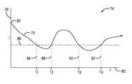
- FIG. 7is a time versus current plot 74 for the battery that displays a “false alarm,” where the current temporarily rises unexpectedly, but that later does develop a defect or failure indication.
- the plot 74comprises a trace 76 corresponding to the typical battery being charged/maintained by the battery charger/maintainer, here again illustrated in terms of a current 78 over time 80 .
- the trace 76begins the charging process normally at an initial high current 82 .
- the currentfalls below a current threshold 86 , indicating that the battery is reaching full charge, as would be expected.
- the trace 76again rises above the threshold 86 .
- this increase in currentcould be a result of normal behavior, such as opening a door, turning on dome lights, or turning on a sound system or other load while the battery is charging/maintaining.
- Such actions while the battery is on the charger/maintainer 18might temporarily cause the current to rise above the current threshold 86 , as shown, but in accordance with the present techniques should not be and are not considered as necessarily indicative of a defective or failing battery (unless they continue beyond the time threshold).
- the currentwill again fall below the current threshold 86 around a third time 90 .
- the batterywill not be identified as potentially defective or failing. If the charging current of the battery again rises above the current threshold 86 , such as at a fourth time 92 , and remains above the threshold for the length of the selected time threshold, then the battery will be identified as potentially defective or failing. In this way, the charging/maintaining system may reduce the number of non-failing batteries 12 that are identified as failing.
- one or more actionsmay be taken when the battery or batteries are determined to be potentially defective or failing.
- Such actionsmay include interrupting further charging or maintaining, altering a charging or maintaining regime, notifying the user, and so forth.
- information on the battery type, design, manufacturing time and place, and/or on the individual batterymay be detected and stored for later evaluation of defects occurring both to individual batteries as well as to groups of batteries.
- Such datamay be stored in the charging/maintaining system, or sent to other monitoring and evaluation systems for processing and analysis.
- other parametersmay be monitored to enable the calculation of the output power of the power conversion circuitry of the battery charger/maintainer.
- the powermay be monitored, such as based on the parameters that may include output current and voltage. It is understood that such a system may include a threshold time, as described above, as well as a power threshold. The power of the battery should fall below the power threshold as it is charged/maintained, and if it does not, or if it rises above the threshold for at least the preset time threshold, the battery may be considered defective or failing.
- One or more of the disclosed embodimentsmay provide one or more technical effects useful in the methods and manufacture of battery charging/maintaining systems.
- certain embodiments of the present approachmay enable improved battery monitoring.
- monitoring a charging output of the battery, and identifying the battery as failing based upon the output power and a time threshold, as set forth abovemay enable the detection of defective or failing batteries while they are charging or maintaining, so that it may be removed from the charger/maintainer.
- the systems and methods for battery monitoringas presently disclosed, may generally enable improved detection of defective or failing batteries during charging and/or maintaining.
- the technical effects and technical problems in the specificationare exemplary and are not limiting. It should be noted that the embodiments described in the specification may have other technical effects and can solve other technical problems.
Landscapes
- Engineering & Computer Science (AREA)
- Power Engineering (AREA)
- Manufacturing & Machinery (AREA)
- Chemical & Material Sciences (AREA)
- Chemical Kinetics & Catalysis (AREA)
- Electrochemistry (AREA)
- General Chemical & Material Sciences (AREA)
- Physics & Mathematics (AREA)
- General Physics & Mathematics (AREA)
- Charge And Discharge Circuits For Batteries Or The Like (AREA)
- Secondary Cells (AREA)
Abstract
Description
Claims (17)
Priority Applications (7)
| Application Number | Priority Date | Filing Date | Title |
|---|---|---|---|
| US13/910,760US9702939B2 (en) | 2012-06-06 | 2013-06-05 | Battery charging and maintaining with defective battery monitoring |
| AU2013271596AAU2013271596B2 (en) | 2012-06-06 | 2013-06-06 | Battery charging and maintaining with defective battery monitoring |
| PCT/US2013/044492WO2013184903A2 (en) | 2012-06-06 | 2013-06-06 | Battery charging and maintaining with defective battery monitoring |
| CN201380041547.XACN104521093B (en) | 2012-06-06 | 2013-06-06 | Battery charging and maintenance with defective battery monitoring |
| MX2014014953AMX343054B (en) | 2012-06-06 | 2013-06-06 | Battery charging and maintaining with defective battery monitoring. |
| EP13800518.6AEP2859643B1 (en) | 2012-06-06 | 2013-06-06 | Battery charging and maintaining with defective battery monitoring |
| CA2875787ACA2875787C (en) | 2012-06-06 | 2013-06-06 | Battery charging and maintaining with defective battery monitoring |
Applications Claiming Priority (2)
| Application Number | Priority Date | Filing Date | Title |
|---|---|---|---|
| US201261656408P | 2012-06-06 | 2012-06-06 | |
| US13/910,760US9702939B2 (en) | 2012-06-06 | 2013-06-05 | Battery charging and maintaining with defective battery monitoring |
Publications (2)
| Publication Number | Publication Date |
|---|---|
| US20130328522A1 US20130328522A1 (en) | 2013-12-12 |
| US9702939B2true US9702939B2 (en) | 2017-07-11 |
Family
ID=49712846
Family Applications (1)
| Application Number | Title | Priority Date | Filing Date |
|---|---|---|---|
| US13/910,760Active2034-05-01US9702939B2 (en) | 2012-06-06 | 2013-06-05 | Battery charging and maintaining with defective battery monitoring |
Country Status (7)
| Country | Link |
|---|---|
| US (1) | US9702939B2 (en) |
| EP (1) | EP2859643B1 (en) |
| CN (1) | CN104521093B (en) |
| AU (1) | AU2013271596B2 (en) |
| CA (1) | CA2875787C (en) |
| MX (1) | MX343054B (en) |
| WO (1) | WO2013184903A2 (en) |
Cited By (3)
| Publication number | Priority date | Publication date | Assignee | Title |
|---|---|---|---|---|
| US20210197688A1 (en)* | 2018-09-28 | 2021-07-01 | Komatsu Ltd. | Charging control device, work machine, and charging control method |
| US20210302039A1 (en)* | 2020-03-24 | 2021-09-30 | Johnson Controls Technology Company | System and method to operate hvac system during voltage variation event |
| US11411409B2 (en)* | 2017-04-28 | 2022-08-09 | Gs Yuasa International Ltd. | Management apparatus, energy storage apparatus, and energy storage system |
Families Citing this family (39)
| Publication number | Priority date | Publication date | Assignee | Title |
|---|---|---|---|---|
| US11764990B2 (en) | 2013-07-26 | 2023-09-19 | Skybell Technologies Ip, Llc | Doorbell communications systems and methods |
| US11909549B2 (en) | 2013-07-26 | 2024-02-20 | Skybell Technologies Ip, Llc | Doorbell communication systems and methods |
| US20170263067A1 (en) | 2014-08-27 | 2017-09-14 | SkyBell Technologies, Inc. | Smart lock systems and methods |
| US10708404B2 (en) | 2014-09-01 | 2020-07-07 | Skybell Technologies Ip, Llc | Doorbell communication and electrical systems |
| US10672238B2 (en) | 2015-06-23 | 2020-06-02 | SkyBell Technologies, Inc. | Doorbell communities |
| US20180343141A1 (en) | 2015-09-22 | 2018-11-29 | SkyBell Technologies, Inc. | Doorbell communication systems and methods |
| US10062251B2 (en)* | 2013-12-06 | 2018-08-28 | SkyBell Technologies, Inc. | Doorbell battery systems |
| US11651665B2 (en) | 2013-07-26 | 2023-05-16 | Skybell Technologies Ip, Llc | Doorbell communities |
| US11889009B2 (en) | 2013-07-26 | 2024-01-30 | Skybell Technologies Ip, Llc | Doorbell communication and electrical systems |
| US9437850B2 (en) | 2014-04-30 | 2016-09-06 | Johnson Controls Technology Company | Battery construction for integration of battery management system and method |
| US12155974B2 (en) | 2014-06-23 | 2024-11-26 | Skybell Technologies Ip, Llc | Doorbell communication systems and methods |
| US20170085843A1 (en) | 2015-09-22 | 2017-03-23 | SkyBell Technologies, Inc. | Doorbell communication systems and methods |
| US11184589B2 (en) | 2014-06-23 | 2021-11-23 | Skybell Technologies Ip, Llc | Doorbell communication systems and methods |
| US11575537B2 (en) | 2015-03-27 | 2023-02-07 | Skybell Technologies Ip, Llc | Doorbell communication systems and methods |
| TW201622294A (en)* | 2014-12-04 | 2016-06-16 | Masterhold Int L Co Ltd | Charging system capable of enhancing charging efficiency and its charging device and power storage apparatus |
| US10742938B2 (en) | 2015-03-07 | 2020-08-11 | Skybell Technologies Ip, Llc | Garage door communication systems and methods |
| US11381686B2 (en) | 2015-04-13 | 2022-07-05 | Skybell Technologies Ip, Llc | Power outlet cameras |
| US11641452B2 (en) | 2015-05-08 | 2023-05-02 | Skybell Technologies Ip, Llc | Doorbell communication systems and methods |
| US9789784B2 (en)* | 2015-05-13 | 2017-10-17 | Ford Global Technologies, Llc | Maintaining a vehicle battery |
| US20180047269A1 (en) | 2015-06-23 | 2018-02-15 | SkyBell Technologies, Inc. | Doorbell communities |
| US10706702B2 (en) | 2015-07-30 | 2020-07-07 | Skybell Technologies Ip, Llc | Doorbell package detection systems and methods |
| KR102401578B1 (en)* | 2015-09-03 | 2022-05-24 | 삼성전자주식회사 | Method for inspecting auxiliary power supply and electronic device adopting the same |
| US12236774B2 (en) | 2015-09-22 | 2025-02-25 | Skybell Technologies Ip, Llc | Doorbell communication systems and methods |
| CN106782266B (en)* | 2016-12-31 | 2020-10-27 | 歌尔科技有限公司 | Display screen drive control method and device and display screen drive control circuit |
| US11509148B2 (en) | 2017-06-26 | 2022-11-22 | Hubbell Incorporated | Distributed charging station |
| US10909825B2 (en) | 2017-09-18 | 2021-02-02 | Skybell Technologies Ip, Llc | Outdoor security systems and methods |
| CN117375167A (en)* | 2018-02-28 | 2024-01-09 | 豪倍公司 | Distributed charging station |
| USD908616S1 (en) | 2018-04-17 | 2021-01-26 | Hubbell Incorporated | Charge center |
| USD909295S1 (en) | 2018-04-18 | 2021-02-02 | Hubbell Incorporated | Charge center |
| DE102018209324A1 (en)* | 2018-06-12 | 2019-12-12 | Bayerische Motoren Werke Aktiengesellschaft | Monitoring of batteries |
| USD942930S1 (en) | 2019-01-17 | 2022-02-08 | Hubbell Incorporated | Charge center |
| CN110187291B (en)* | 2019-06-10 | 2021-10-22 | 天津普兰能源科技有限公司 | Lithium ion battery self-discharge rapid screening device and screening method based on direct-current impedance |
| CN110501645B (en)* | 2019-08-02 | 2021-11-30 | 华人运通(江苏)技术有限公司 | Insulation fault detection method and device, electric vehicle and computer storage medium |
| WO2021041354A1 (en) | 2019-08-24 | 2021-03-04 | Skybell Technologies Ip, Llc | Doorbell communication systems and methods |
| USD918893S1 (en) | 2019-10-14 | 2021-05-11 | Hubbell Incorporated | Kiosk |
| WO2021076635A1 (en)* | 2019-10-15 | 2021-04-22 | Briggs & Stratton, Llc | Electric vehicle with multiple ports |
| USD941749S1 (en) | 2019-11-13 | 2022-01-25 | Hubbell Incorporated | Battery |
| USD982511S1 (en) | 2019-12-13 | 2023-04-04 | Hubbell Incorporated | Charge center |
| USD937771S1 (en) | 2019-12-13 | 2021-12-07 | Hubbell Incorporated | Charging station |
Citations (15)
| Publication number | Priority date | Publication date | Assignee | Title |
|---|---|---|---|---|
| US3590326A (en)* | 1970-06-18 | 1971-06-29 | Westinghouse Electric Corp | Overcurrent protective device |
| US3835362A (en)* | 1973-08-09 | 1974-09-10 | Safe Flight Instrument | Defective battery condition/charging system warning device |
| US4820965A (en)* | 1987-03-23 | 1989-04-11 | Maurice A. Sween | Control circuit for battery charger |
| US6124700A (en)* | 1995-08-10 | 2000-09-26 | Sony Corporation | Charging method, charging equipment, and integrated circuit |
| US6144185A (en)* | 1999-03-22 | 2000-11-07 | Johnson Controls Technology Company | Method and apparatus for determining the condition of a battery through the use of multiple battery tests |
| US6259254B1 (en)* | 1998-07-27 | 2001-07-10 | Midtronics, Inc. | Apparatus and method for carrying out diagnostic tests on batteries and for rapidly charging batteries |
| US6453249B1 (en)* | 1999-01-28 | 2002-09-17 | Honda Giken Kogyo Kabushiki Kaisha | Apparatus for judging deterioration of battery |
| US20030141845A1 (en)* | 2002-01-25 | 2003-07-31 | Michael Krieger | High frequency battery charger and method of operating same |
| US20060139010A1 (en)* | 2004-12-23 | 2006-06-29 | Ligong Wang | Method for verifying smart battery failures by measuring input charging voltage and associated systems |
| US20060145658A1 (en)* | 2004-12-31 | 2006-07-06 | Jason Auto Technology Co., Ltd. | Method and device for battery charger and diagnosis with detectable battery energy barrier |
| GB2440065A (en) | 2004-12-23 | 2008-01-16 | Dell Products Lp | Verifying smart battery failures by measuring input charging voltage |
| CN101329381A (en) | 2008-07-28 | 2008-12-24 | 庞元俊 | Method for detecting short circuit fault with current change rate |
| US20090195211A1 (en)* | 2008-01-31 | 2009-08-06 | Ligong Wang | Method and system for regulating current discharge during battery discharge conditioning cycle |
| US20100127663A1 (en) | 2008-11-26 | 2010-05-27 | Kimihiko Furukawa | Battery system with relays |
| US20110302437A1 (en) | 2010-06-07 | 2011-12-08 | Itron, Inc. | Switch-off of a micro controller unit in battery mode |
- 2013
- 2013-06-05USUS13/910,760patent/US9702939B2/enactiveActive
- 2013-06-06WOPCT/US2013/044492patent/WO2013184903A2/enactiveApplication Filing
- 2013-06-06EPEP13800518.6Apatent/EP2859643B1/enactiveActive
- 2013-06-06CNCN201380041547.XApatent/CN104521093B/enactiveActive
- 2013-06-06CACA2875787Apatent/CA2875787C/enactiveActive
- 2013-06-06AUAU2013271596Apatent/AU2013271596B2/enactiveActive
- 2013-06-06MXMX2014014953Apatent/MX343054B/enactiveIP Right Grant
Patent Citations (15)
| Publication number | Priority date | Publication date | Assignee | Title |
|---|---|---|---|---|
| US3590326A (en)* | 1970-06-18 | 1971-06-29 | Westinghouse Electric Corp | Overcurrent protective device |
| US3835362A (en)* | 1973-08-09 | 1974-09-10 | Safe Flight Instrument | Defective battery condition/charging system warning device |
| US4820965A (en)* | 1987-03-23 | 1989-04-11 | Maurice A. Sween | Control circuit for battery charger |
| US6124700A (en)* | 1995-08-10 | 2000-09-26 | Sony Corporation | Charging method, charging equipment, and integrated circuit |
| US6259254B1 (en)* | 1998-07-27 | 2001-07-10 | Midtronics, Inc. | Apparatus and method for carrying out diagnostic tests on batteries and for rapidly charging batteries |
| US6453249B1 (en)* | 1999-01-28 | 2002-09-17 | Honda Giken Kogyo Kabushiki Kaisha | Apparatus for judging deterioration of battery |
| US6144185A (en)* | 1999-03-22 | 2000-11-07 | Johnson Controls Technology Company | Method and apparatus for determining the condition of a battery through the use of multiple battery tests |
| US20030141845A1 (en)* | 2002-01-25 | 2003-07-31 | Michael Krieger | High frequency battery charger and method of operating same |
| US20060139010A1 (en)* | 2004-12-23 | 2006-06-29 | Ligong Wang | Method for verifying smart battery failures by measuring input charging voltage and associated systems |
| GB2440065A (en) | 2004-12-23 | 2008-01-16 | Dell Products Lp | Verifying smart battery failures by measuring input charging voltage |
| US20060145658A1 (en)* | 2004-12-31 | 2006-07-06 | Jason Auto Technology Co., Ltd. | Method and device for battery charger and diagnosis with detectable battery energy barrier |
| US20090195211A1 (en)* | 2008-01-31 | 2009-08-06 | Ligong Wang | Method and system for regulating current discharge during battery discharge conditioning cycle |
| CN101329381A (en) | 2008-07-28 | 2008-12-24 | 庞元俊 | Method for detecting short circuit fault with current change rate |
| US20100127663A1 (en) | 2008-11-26 | 2010-05-27 | Kimihiko Furukawa | Battery system with relays |
| US20110302437A1 (en) | 2010-06-07 | 2011-12-08 | Itron, Inc. | Switch-off of a micro controller unit in battery mode |
Non-Patent Citations (2)
| Title |
|---|
| CN 201380041547.X Office Action dated Aug. 3, 2016. |
| International Search Report and Written Opinion for PCT Application No. PCT/US2013/044492 dated Mar. 5, 2014; 9 pgs. |
Cited By (5)
| Publication number | Priority date | Publication date | Assignee | Title |
|---|---|---|---|---|
| US11411409B2 (en)* | 2017-04-28 | 2022-08-09 | Gs Yuasa International Ltd. | Management apparatus, energy storage apparatus, and energy storage system |
| US20210197688A1 (en)* | 2018-09-28 | 2021-07-01 | Komatsu Ltd. | Charging control device, work machine, and charging control method |
| US11945327B2 (en)* | 2018-09-28 | 2024-04-02 | Komatsu Ltd. | Charging control device, work machine, and charging control method |
| US20210302039A1 (en)* | 2020-03-24 | 2021-09-30 | Johnson Controls Technology Company | System and method to operate hvac system during voltage variation event |
| US11768000B2 (en)* | 2020-03-24 | 2023-09-26 | Johnson Controls Tyco IP Holdings LLP | System and method to operate HVAC system during voltage variation event |
Also Published As
| Publication number | Publication date |
|---|---|
| CN104521093B (en) | 2018-02-23 |
| MX2014014953A (en) | 2015-10-29 |
| EP2859643A2 (en) | 2015-04-15 |
| CN104521093A (en) | 2015-04-15 |
| US20130328522A1 (en) | 2013-12-12 |
| WO2013184903A3 (en) | 2014-04-17 |
| CA2875787A1 (en) | 2013-12-12 |
| EP2859643B1 (en) | 2021-03-24 |
| WO2013184903A2 (en) | 2013-12-12 |
| AU2013271596B2 (en) | 2015-10-08 |
| AU2013271596A1 (en) | 2015-01-15 |
| CA2875787C (en) | 2018-07-31 |
| MX343054B (en) | 2016-10-21 |
Similar Documents
| Publication | Publication Date | Title |
|---|---|---|
| US9702939B2 (en) | Battery charging and maintaining with defective battery monitoring | |
| CN107134821B (en) | Electric automobile and low-voltage storage battery electric quantity management system thereof | |
| JP4377164B2 (en) | Power storage device abnormality detection method, power storage device abnormality detection device, and power storage system | |
| CN114523877A (en) | System and method for managing a vehicle battery | |
| JP5520580B2 (en) | Storage battery cell short-circuit detection method and detection device | |
| US20160103188A1 (en) | Method for monitoring the state of a battery in a motor vehicle | |
| EP2161812A1 (en) | Power supply system, and power supply control method and power supply control program employed in power supply system | |
| US10381692B2 (en) | Method for monitoring the state of a battery in a motor vehicle | |
| KR20180023140A (en) | Power Relay Assembly fault controlling system and the method thereof | |
| EP4398378A2 (en) | Method and arrangement for classifying a voltage fault condition in an electrical storage system | |
| CN110036305A (en) | For running the method and battery management device thus of the traction battery group of motor vehicle | |
| WO2014085499A1 (en) | Transient detection of an exceptional charge event in a series connected battery element | |
| KR100984556B1 (en) | A bettery restoration unit and restoration method | |
| JP5938633B2 (en) | Battery chargeability determination device | |
| CN115583152B (en) | A method and system for detecting the connection status of a DCDC module output line | |
| JP2016096592A (en) | Monitoring device for battery pack, power storage device and wire breaking diagnosis method | |
| CN101669264A (en) | Method and device for determining an equalizing charge of an accumulator | |
| JP4374982B2 (en) | Storage battery deterioration determination device and storage battery provided with the same | |
| WO2015022731A1 (en) | Battery monitoring apparatus, battery system, and vehicle control system | |
| CN111208444A (en) | Power battery system branch circuit breaking diagnosis method and device | |
| JP2009054302A (en) | Vehicle battery history reading device | |
| CN115453385A (en) | Method, detection device, and motor vehicle for detecting a battery cell failure state of a battery | |
| US20160103182A1 (en) | Secondary battery status detection device and secondary battery status detection method | |
| JP2009040070A (en) | Battery state detection device | |
| CN116409150A (en) | Abnormal monitoring method of electric vehicle and its power battery sensor |
Legal Events
| Date | Code | Title | Description |
|---|---|---|---|
| AS | Assignment | Owner name:JOHNSON CONTROLS TECHNOLOGY COMPANY, MICHIGAN Free format text:ASSIGNMENT OF ASSIGNORS INTEREST;ASSIGNORS:BROCKMAN, DARYL C.;LIEDHEGNER, JOSEPH E.;REEL/FRAME:030560/0787 Effective date:20130605 | |
| STCF | Information on status: patent grant | Free format text:PATENTED CASE | |
| AS | Assignment | Owner name:CPS TECHNOLOGY HOLDINGS LLC, NEW YORK Free format text:ASSIGNMENT OF ASSIGNORS INTEREST;ASSIGNOR:JOHNSON CONTROLS TECHNOLOGY COMPANY;REEL/FRAME:049550/0769 Effective date:20190430 | |
| AS | Assignment | Owner name:CITIBANK N.A., AS COLLATERAL AGENT, DELAWARE Free format text:FIRST LIEN PATENT SECURITY AGREEMENT;ASSIGNOR:CPS TECHNOLOGY HOLDINGS LLC;REEL/FRAME:050229/0029 Effective date:20190827 Owner name:CITIBANK N.A., AS COLLATERAL AGENT, NEW YORK Free format text:ABL PATENT SECURITY AGREEMENT;ASSIGNOR:CPS TECHNOLOGY HOLDINGS LLC;REEL/FRAME:050229/0079 Effective date:20190827 | |
| MAFP | Maintenance fee payment | Free format text:PAYMENT OF MAINTENANCE FEE, 4TH YEAR, LARGE ENTITY (ORIGINAL EVENT CODE: M1551); ENTITY STATUS OF PATENT OWNER: LARGE ENTITY Year of fee payment:4 | |
| MAFP | Maintenance fee payment | Free format text:PAYMENT OF MAINTENANCE FEE, 8TH YEAR, LARGE ENTITY (ORIGINAL EVENT CODE: M1552); ENTITY STATUS OF PATENT OWNER: LARGE ENTITY Year of fee payment:8 |