US9700223B2 - Method for forming a component of a wearable monitor - Google Patents
Method for forming a component of a wearable monitorDownload PDFInfo
- Publication number
- US9700223B2 US9700223B2US15/266,767US201615266767AUS9700223B2US 9700223 B2US9700223 B2US 9700223B2US 201615266767 AUS201615266767 AUS 201615266767AUS 9700223 B2US9700223 B2US 9700223B2
- Authority
- US
- United States
- Prior art keywords
- health
- monitor
- component
- flexible
- subject
- Prior art date
- Legal status (The legal status is an assumption and is not a legal conclusion. Google has not performed a legal analysis and makes no representation as to the accuracy of the status listed.)
- Active
Links
Images


Classifications
- A—HUMAN NECESSITIES
- A61—MEDICAL OR VETERINARY SCIENCE; HYGIENE
- A61B—DIAGNOSIS; SURGERY; IDENTIFICATION
- A61B5/00—Measuring for diagnostic purposes; Identification of persons
- A61B5/72—Signal processing specially adapted for physiological signals or for diagnostic purposes
- A61B5/7203—Signal processing specially adapted for physiological signals or for diagnostic purposes for noise prevention, reduction or removal
- A61B5/7207—Signal processing specially adapted for physiological signals or for diagnostic purposes for noise prevention, reduction or removal of noise induced by motion artifacts
- A61B5/7214—Signal processing specially adapted for physiological signals or for diagnostic purposes for noise prevention, reduction or removal of noise induced by motion artifacts using signal cancellation, e.g. based on input of two identical physiological sensors spaced apart, or based on two signals derived from the same sensor, for different optical wavelengths
- A61B5/04085—
- A—HUMAN NECESSITIES
- A61—MEDICAL OR VETERINARY SCIENCE; HYGIENE
- A61B—DIAGNOSIS; SURGERY; IDENTIFICATION
- A61B5/00—Measuring for diagnostic purposes; Identification of persons
- A61B5/0059—Measuring for diagnostic purposes; Identification of persons using light, e.g. diagnosis by transillumination, diascopy, fluorescence
- A61B5/04087—
- A—HUMAN NECESSITIES
- A61—MEDICAL OR VETERINARY SCIENCE; HYGIENE
- A61B—DIAGNOSIS; SURGERY; IDENTIFICATION
- A61B5/00—Measuring for diagnostic purposes; Identification of persons
- A61B5/103—Measuring devices for testing the shape, pattern, colour, size or movement of the body or parts thereof, for diagnostic purposes
- A61B5/11—Measuring movement of the entire body or parts thereof, e.g. head or hand tremor or mobility of a limb
- A61B5/1118—Determining activity level
- A—HUMAN NECESSITIES
- A61—MEDICAL OR VETERINARY SCIENCE; HYGIENE
- A61B—DIAGNOSIS; SURGERY; IDENTIFICATION
- A61B5/00—Measuring for diagnostic purposes; Identification of persons
- A61B5/103—Measuring devices for testing the shape, pattern, colour, size or movement of the body or parts thereof, for diagnostic purposes
- A61B5/11—Measuring movement of the entire body or parts thereof, e.g. head or hand tremor or mobility of a limb
- A61B5/1123—Discriminating type of movement, e.g. walking or running
- A—HUMAN NECESSITIES
- A61—MEDICAL OR VETERINARY SCIENCE; HYGIENE
- A61B—DIAGNOSIS; SURGERY; IDENTIFICATION
- A61B5/00—Measuring for diagnostic purposes; Identification of persons
- A61B5/24—Detecting, measuring or recording bioelectric or biomagnetic signals of the body or parts thereof
- A61B5/25—Bioelectric electrodes therefor
- A61B5/251—Means for maintaining electrode contact with the body
- A61B5/257—Means for maintaining electrode contact with the body using adhesive means, e.g. adhesive pads or tapes
- A61B5/259—Means for maintaining electrode contact with the body using adhesive means, e.g. adhesive pads or tapes using conductive adhesive means, e.g. gels
- A—HUMAN NECESSITIES
- A61—MEDICAL OR VETERINARY SCIENCE; HYGIENE
- A61B—DIAGNOSIS; SURGERY; IDENTIFICATION
- A61B5/00—Measuring for diagnostic purposes; Identification of persons
- A61B5/24—Detecting, measuring or recording bioelectric or biomagnetic signals of the body or parts thereof
- A61B5/25—Bioelectric electrodes therefor
- A61B5/279—Bioelectric electrodes therefor specially adapted for particular uses
- A61B5/28—Bioelectric electrodes therefor specially adapted for particular uses for electrocardiography [ECG]
- A—HUMAN NECESSITIES
- A61—MEDICAL OR VETERINARY SCIENCE; HYGIENE
- A61B—DIAGNOSIS; SURGERY; IDENTIFICATION
- A61B5/00—Measuring for diagnostic purposes; Identification of persons
- A61B5/72—Signal processing specially adapted for physiological signals or for diagnostic purposes
- A61B5/7203—Signal processing specially adapted for physiological signals or for diagnostic purposes for noise prevention, reduction or removal
- A—HUMAN NECESSITIES
- A61—MEDICAL OR VETERINARY SCIENCE; HYGIENE
- A61B—DIAGNOSIS; SURGERY; IDENTIFICATION
- A61B5/00—Measuring for diagnostic purposes; Identification of persons
- A61B5/72—Signal processing specially adapted for physiological signals or for diagnostic purposes
- A61B5/7225—Details of analogue processing, e.g. isolation amplifier, gain or sensitivity adjustment, filtering, baseline or drift compensation
- A—HUMAN NECESSITIES
- A61—MEDICAL OR VETERINARY SCIENCE; HYGIENE
- A61B—DIAGNOSIS; SURGERY; IDENTIFICATION
- A61B5/00—Measuring for diagnostic purposes; Identification of persons
- A61B5/72—Signal processing specially adapted for physiological signals or for diagnostic purposes
- A61B5/7271—Specific aspects of physiological measurement analysis
- A—HUMAN NECESSITIES
- A61—MEDICAL OR VETERINARY SCIENCE; HYGIENE
- A61B—DIAGNOSIS; SURGERY; IDENTIFICATION
- A61B5/00—Measuring for diagnostic purposes; Identification of persons
- A61B5/74—Details of notification to user or communication with user or patient; User input means
- A61B5/742—Details of notification to user or communication with user or patient; User input means using visual displays
- G06F19/3481—
- G—PHYSICS
- G16—INFORMATION AND COMMUNICATION TECHNOLOGY [ICT] SPECIALLY ADAPTED FOR SPECIFIC APPLICATION FIELDS
- G16H—HEALTHCARE INFORMATICS, i.e. INFORMATION AND COMMUNICATION TECHNOLOGY [ICT] SPECIALLY ADAPTED FOR THE HANDLING OR PROCESSING OF MEDICAL OR HEALTHCARE DATA
- G16H20/00—ICT specially adapted for therapies or health-improving plans, e.g. for handling prescriptions, for steering therapy or for monitoring patient compliance
- G16H20/40—ICT specially adapted for therapies or health-improving plans, e.g. for handling prescriptions, for steering therapy or for monitoring patient compliance relating to mechanical, radiation or invasive therapies, e.g. surgery, laser therapy, dialysis or acupuncture
- G—PHYSICS
- G16—INFORMATION AND COMMUNICATION TECHNOLOGY [ICT] SPECIALLY ADAPTED FOR SPECIFIC APPLICATION FIELDS
- G16H—HEALTHCARE INFORMATICS, i.e. INFORMATION AND COMMUNICATION TECHNOLOGY [ICT] SPECIALLY ADAPTED FOR THE HANDLING OR PROCESSING OF MEDICAL OR HEALTHCARE DATA
- G16H50/00—ICT specially adapted for medical diagnosis, medical simulation or medical data mining; ICT specially adapted for detecting, monitoring or modelling epidemics or pandemics
- G16H50/20—ICT specially adapted for medical diagnosis, medical simulation or medical data mining; ICT specially adapted for detecting, monitoring or modelling epidemics or pandemics for computer-aided diagnosis, e.g. based on medical expert systems
- A—HUMAN NECESSITIES
- A61—MEDICAL OR VETERINARY SCIENCE; HYGIENE
- A61B—DIAGNOSIS; SURGERY; IDENTIFICATION
- A61B2560/00—Constructional details of operational features of apparatus; Accessories for medical measuring apparatus
- A61B2560/02—Operational features
- A61B2560/0204—Operational features of power management
- A61B2560/0214—Operational features of power management of power generation or supply
- A—HUMAN NECESSITIES
- A61—MEDICAL OR VETERINARY SCIENCE; HYGIENE
- A61B—DIAGNOSIS; SURGERY; IDENTIFICATION
- A61B2560/00—Constructional details of operational features of apparatus; Accessories for medical measuring apparatus
- A61B2560/04—Constructional details of apparatus
- A61B2560/0406—Constructional details of apparatus specially shaped apparatus housings
- A61B2560/0412—Low-profile patch shaped housings
- A—HUMAN NECESSITIES
- A61—MEDICAL OR VETERINARY SCIENCE; HYGIENE
- A61B—DIAGNOSIS; SURGERY; IDENTIFICATION
- A61B2562/00—Details of sensors; Constructional details of sensor housings or probes; Accessories for sensors
- A61B2562/02—Details of sensors specially adapted for in-vivo measurements
- A61B2562/0219—Inertial sensors, e.g. accelerometers, gyroscopes, tilt switches
- A—HUMAN NECESSITIES
- A61—MEDICAL OR VETERINARY SCIENCE; HYGIENE
- A61B—DIAGNOSIS; SURGERY; IDENTIFICATION
- A61B2562/00—Details of sensors; Constructional details of sensor housings or probes; Accessories for sensors
- A61B2562/12—Manufacturing methods specially adapted for producing sensors for in-vivo measurements
- A61B2562/125—Manufacturing methods specially adapted for producing sensors for in-vivo measurements characterised by the manufacture of electrodes
- A—HUMAN NECESSITIES
- A61—MEDICAL OR VETERINARY SCIENCE; HYGIENE
- A61B—DIAGNOSIS; SURGERY; IDENTIFICATION
- A61B2562/00—Details of sensors; Constructional details of sensor housings or probes; Accessories for sensors
- A61B2562/16—Details of sensor housings or probes; Details of structural supports for sensors
- G—PHYSICS
- G01—MEASURING; TESTING
- G01C—MEASURING DISTANCES, LEVELS OR BEARINGS; SURVEYING; NAVIGATION; GYROSCOPIC INSTRUMENTS; PHOTOGRAMMETRY OR VIDEOGRAMMETRY
- G01C22/00—Measuring distance traversed on the ground by vehicles, persons, animals or other moving solid bodies, e.g. using odometers, using pedometers
- G01C22/006—Pedometers
- G06F19/3418—
- G—PHYSICS
- G16—INFORMATION AND COMMUNICATION TECHNOLOGY [ICT] SPECIALLY ADAPTED FOR SPECIFIC APPLICATION FIELDS
- G16H—HEALTHCARE INFORMATICS, i.e. INFORMATION AND COMMUNICATION TECHNOLOGY [ICT] SPECIALLY ADAPTED FOR THE HANDLING OR PROCESSING OF MEDICAL OR HEALTHCARE DATA
- G16H10/00—ICT specially adapted for the handling or processing of patient-related medical or healthcare data
- G16H10/60—ICT specially adapted for the handling or processing of patient-related medical or healthcare data for patient-specific data, e.g. for electronic patient records
- G—PHYSICS
- G16—INFORMATION AND COMMUNICATION TECHNOLOGY [ICT] SPECIALLY ADAPTED FOR SPECIFIC APPLICATION FIELDS
- G16H—HEALTHCARE INFORMATICS, i.e. INFORMATION AND COMMUNICATION TECHNOLOGY [ICT] SPECIALLY ADAPTED FOR THE HANDLING OR PROCESSING OF MEDICAL OR HEALTHCARE DATA
- G16H40/00—ICT specially adapted for the management or administration of healthcare resources or facilities; ICT specially adapted for the management or operation of medical equipment or devices
- G16H40/60—ICT specially adapted for the management or administration of healthcare resources or facilities; ICT specially adapted for the management or operation of medical equipment or devices for the operation of medical equipment or devices
- G16H40/67—ICT specially adapted for the management or administration of healthcare resources or facilities; ICT specially adapted for the management or operation of medical equipment or devices for the operation of medical equipment or devices for remote operation
Definitions
- the technologyrelates to wearable devices that are configured to monitor physiological parameters (heart rate, heart rate variability, respiratory rate, etc.) of a subject and/or physical activity performed by the subject.
- the FitLinxx® ActiPed+(available from FitLinxx, Shelton, Conn., USA) is a small device that can be clipped to a shoe and used to monitor walking and running activities by the user.
- an on-board accelerometeroutputs data that is stored on the device for subsequent transmission to a computer system.
- the computer systemcan analyze the data to determine activity type, and calculate various activity parameters (e.g., duration of activity, total steps, distance traveled, and calories burned). Results of the data analysis may be presented on the computer's display, so that a user may review details of his or her activity.
- the resultsmay be stored, so that the user can maintain a record of exercise regimens and track progress toward exercise goals, or so that the data may be used by medical personnel to track recovery from an illness or injury.
- Other modern activity monitorsperform similar functions with varying degrees of accuracy.
- activity monitorsare configured to be attached to a subject's clothing or strapped to a subject's limb.
- some activity monitorsmay clip on clothing, or be configured to clip on or lace in a shoe.
- Activity monitors that attach to clothingare generally not adapted to sense a physiological parameter of the subject.
- Some activity monitors that may be worn on the wrist or ankle of a subjectmay be adapted to sense heart rate, but these monitors generally cannot measure details of cardiac waveform to obtain information such as heart-rate variability (HRV) or cardiac abnormalities such as arrhythmias.
- HRVheart-rate variability
- the health-monitor patchcomprises a flexible and waterproof strip, and is designed to be worn for extended periods of time.
- Two monitoring electrodes on the stripmay contact the skin of the subject and be used to collect cardiac waveform data.
- At least a third electrodemay be included to suppress electrical noise and improve the quality of data collected by the health-monitor patch.
- the cardiac waveform datamay be analyzed to determine various physiological parameters of a subject, such as heart rate, heart-rate variability, caloric burn, resting heart rate, recovery from a workout, respiratory rate, etc.
- the health-monitor patchmay further include an accelerometer from which acceleration data may be analyzed to determine parameters associated with motion of the subject (e.g., body orientation of the subject, type of activity performed by the subject, intensity of activity performed by the subject, etc.).
- a health-monitor patchmay comprise a flexible strip assembly, which may house electrical components of the health-monitor patch, and a replaceable electrode strip that adheres to the flexible strip assembly.
- the replaceable electrode stripmay provide replaceable adhesion and electrical connections between the subject and the flexible strip assembly.
- Other embodiments of the health-monitor patchmay be single-use, disposable strips that include electronics and adhesive layers for attaching to a subject's skin.
- a disposable health-monitor patchmay be a low-cost device suitable for single-use applications, such as for out-patient health monitoring.
- a health-monitor patchmay include an accelerometer, processor, and machine-readable instructions that adapt the health-monitor patch to perform a variety of different functions and data analyses as described, for example, in U.S. Patent Application Pub. No. 2015-0119728 and in U.S. Patent Application Pub. No. 2013-0217979, the disclosures of which were incorporated by reference above in their entirety.
- a health-monitor patchmay comprise a cardiac sensor comprising two monitor electrodes that are configured to receive two signals from two locations on the skin of the subject.
- a health-monitor patchmay further include a noise electrode configured to receive a signal from the skin of the subject at a location separate from the two locations of the two monitor electrodes.
- a health-monitor patchmay further include an electronic assembly comprising a processor configured to process signals from the two monitor electrodes.
- Some embodimentsrelate to methods for operating a health-monitor patch. Some methods of operation may include acts of receiving two electrical signals at two monitor electrodes of the health-monitor patch, wherein the two monitor electrodes contact the skin of a subject and are separated by a distance, conducting electrical signals from the two monitor electrodes over two conductive paths to two signal inputs of an electronic circuit mounted within the health-monitor patch, receiving an electrical signal from a noise electrode that contacts the skin of the subject and is located between the two monitor electrodes, and conducting the electrical signal from the noise electrode to a conductive shield, such as an ESD shield, that extends at least part way over the two conductive paths.
- the conductive shieldmay also extend over the electronic circuit.
- FIG. 1Adepicts a plan view of a health-monitor patch, according to some embodiments
- FIG. 1Bdepicts an elevation view of a health-monitor patch, according to some embodiments
- FIG. 1Cdepicts an underside view of a health-monitor patch, according to some embodiments.
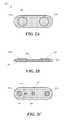
- FIG. 2Adepicts a plan view of a disposable health-monitor patch, according to some embodiments
- FIG. 2Bdepicts an elevation view of a disposable health-monitor patch, according to some embodiments.
- FIG. 2Cdepicts an underside view of a disposable health-monitor patch, according to some embodiments.
- FIG. 3illustrates electronic components that may be included in a health-monitor patch, according to some embodiments
- FIG. 4depicts an exploded view of a disposable health-monitor patch, according to some embodiments.
- FIG. 5illustrates a noise suppression configuration and conductive adhesive in a circuit of a health-monitor patch, according to some embodiments
- FIG. 6illustrates infused conductors in a flexible strip assembly, according to some embodiments
- FIG. 7Adepicts an exploded view of components for a replaceable electrode strip, according to some embodiments.
- FIG. 7Bdepicts a cross section of a replaceable electrode strip, according to some embodiments.
- FIG. 8illustrates a cardiac waveform
- FIG. 9illustrates a cardiac waveform obtained with a health-monitor patch.
- a health-monitor patch 100is depicted in FIG. 1A .
- a health-monitor patchmay be formed from flexible materials and configured to adhere to the skin of a person.
- a health-monitor patchmay include at least one accelerometer for sensing motion and/or activities of a subject, and/or may include electrodes, one or more lasers, one or more light-emitting diodes, one or more photodiodes, one or more temperature sensors and/or other sensors for sensing one or more physiological parameters of a subject.
- a flexible patch-type devicethat having electrodes and/or other sensors that can directly contact a subject's skin can provide more accurate information about a subject's biophysical parameters (such as cardiac waveform, body temperature, respiratory rate, blood oxygenation level, blood glucose level, etc.), which conventional pedometers may not be able to provide.
- a patch deviceis preferably located in the vicinity of a subject's heart and includes two or more electrodes spaced a distance apart.
- a health-monitor patchis preferably flexible so that it's sensing electrodes can remain in contact with the skin of the subject as the subject moves.
- a health-monitor patch attached to a subject's torsocan provide more reliable information about a subject's position (lying, sitting, standing) than a conventional activity monitor that straps to a subject's wrist or ankle.
- Torso orientationcan be helpful when identifying a type of activity that a subject is performing (e.g., distinguishing rowing from cycling or cycling from running) or identifying a resting state of a subject. Torso orientation can also be helpful when monitoring patients. For example, an increased heart rate accompanied by data indicating the patient has changed from a lying position to a vertical and/or walking orientation may be of no concern, whereas an increased heart rate while the patient remains in a lying position may require the attention of a caregiver.
- the inventorshave further conceived of structures, circuits, processes, and combinations of materials that provide a waterproof health-monitor patch, according to some embodiments, and a low-cost disposable health-monitor patch, according to some embodiments. Further details of a health-monitor patch are described below.
- a health-monitor patch 100may include a first end region 110 a and a second end region 110 b .
- a health-monitor patchmay comprise a flexible strip assembly 105 that may or may not have an open center 120 .
- one or more flexible ribs 107may connect the first end region 110 a and the second end region 110 b .
- a center portion of the flexible strip assembly 105may be thin or otherwise configured to provide flexible bending and twisting between the first end region and the second end region.
- a width W of a health-monitor patch 100may be between approximately 10 mm and approximately 50 mm, according to some embodiments.
- a health-monitor patch 100may comprise enlarged lobes at the end regions 110 a , 110 b as shown in the drawing. Electronics of a health-monitor patch may be housed within the lobes.
- An overall length L of a health-monitor patch 100may be between approximately 50 mm and approximately 150 mm.
- a height H of a health-monitor patchmay be between approximately 3 mm and approximately 10 mm.
- the flexible strip assemblymay comprise a flexible polymer such as, but not limited to, silicone.
- a replaceable electrode strip 150may be adhered, temporarily, to a lower surface of a health-monitor patch 100 , as depicted in FIG. 1B .
- the replaceable electrode stripmay provide adhesion, electrical connections, and a waterproof seal between the flexible strip assembly and the skin of a subject.
- the replaceable electrode stripmay be peeled off of the lower surface of the flexible strip assembly 105 and replaced with a new replaceable electrode strip 150 .
- a usermay adhere a health-monitor patch 100 to their skin for a period of time (e.g., one or several days, a week, or more), and then remove the health-monitor patch, replace the replaceable electrode strip 150 , and then re-adhere the health-monitor patch to their skin for continued monitoring of activity and physiological parameters.
- a period of timee.g., one or several days, a week, or more
- FIG. 1CA bottom-side or skin-side view of a health-monitor patch having a replaceable electrode strip 150 is illustrated in FIG. 1C , according to some embodiments.
- the replaceable electrode stripmay include an adhesion surface 152 configured to adhere to a subject's skin.
- the replaceable electrode stripmay comprise two or more electrodes 160 a , 160 b that provide electrical contact to the subject's skin, and electrically connect with electronic circuitry inside the flexible strip assembly 105 .
- a first monitor electrode 160 ais located at a first end of the replaceable electrode strip 150
- a second monitor electrode 160 bis located at a second end of the replaceable electrode strip.
- a distance D between the first monitor electrode and second monitor electrodemay be between approximately 50 mm and approximately 90 mm.
- the first monitor electrode 160 a and second monitor electrode 160 bmay comprise hydrogel electrodes in some embodiments, or may comprise other flexible electrodes for contacting a subject's skin.
- a width of the replaceable electrode strip 150may be between approximately 10 mm and approximately 50 mm, according to some embodiments.
- noise electrodes 170located separately from the first monitor electrode 160 a and the second monitor electrode 160 b .
- the noise electrode(s) 170may be located between the monitor electrodes 160 a , 160 b .
- a noise electrodemay also comprise a hydrogel electrode or other flexible electrode.
- a noise electrode 170may be located approximately half-way between the first monitor electrode and the second monitor electrode.
- one or more noise electrodesmay be placed closer to one or the other of the first monitor electrode and second monitor electrode or at other locations on the strip 150 .
- a noise electrodemay provide an electrical contact to the skin of a subject and further connect electrically to noise cancellation circuitry within the flexible strip assembly 105 .
- a disposable health-monitor patch 200may comprise a flexible strip assembly 205 that includes a first end region 210 a and a second and region 210 b .
- the length L and width W of a disposable health-monitor patch 200may be of approximately the same corresponding dimensions for a health-monitor patch 100 described above in connection with FIG. 1A .
- a disposable health-monitor patch 200may have a lower profile, and a height that is between approximately 2 mm and approximately 8 mm.
- a flexible strip assembly 205may be more uniform in height along its length, and formed from a plurality of flexible layers of materials. In some embodiments, it may include bulged end regions 210 a , 210 b that accommodate the device's electronics (e.g., a PCB assembly and battery).
- a disposable health-monitor patch 200may not have a replaceable electrode strip 150 , but may include an adhesion surface 252 .
- a disposable health-monitor patch 200may have a release liner (shown in FIG. 7A ) located over the adhesion surface 252 that may be removed just prior to adhesion of the disposable health-monitor patch to the skin of a subject.
- a disposable health-monitor patchmay operate between approximately one day and approximately 14 days on a subject, and then be removed and disposed.
- FIG. 2CA plan-view illustration of an adhesion surface 252 of a disposable health-monitor patch 200 is depicted in FIG. 2C , according to some embodiments.
- the adhesion surface 252may accommodate a first monitor electrode 260 a and a second monitor electrode 260 b .
- the monitor electrodesmay be separated by a distance between approximately 50 mm and approximately 90 mm, according to some implementations. Between the monitor electrodes, or at some other location on the adhesion surface 252 , there may be one or more noise electrodes 270 .
- the monitor electrodesmay provide an electrical connection to the patient's skin and to sensing and data analysis circuitry within the disposable health-monitor patch.
- the one or more noise electrodesmay provide electrical connection to the subject's skin and to noise cancellation circuitry within the disposable health-monitor patch 200 .
- one or more light-emitting devices 286e.g., laser(s), LED(s)
- backscattered lightto pass through to one or more photodiodes 287 .
- a health-monitor patchmay collect physiological data (e.g., cardiac data, temperature data, blood oxygenation data, etc.) and/or motion data (e.g., accelerometer data) from one or more of its sensors.
- physiological datae.g., cardiac data, temperature data, blood oxygenation data, etc.
- motion datae.g., accelerometer data
- collected datamay be offloaded to a remote device (e.g., a smart phone, a laptop, a tablet, a computer, etc.) which may process the collected data.
- Data accumulated on a health-monitor patchmay be downloaded via a wireless connection. Examples of data processing and data transfer are described in further detail in U.S. Patent Application Pub. No. 2015-0119728, incorporated by reference above.
- FIG. 3depicts some components and an example circuit 300 that may be implemented in a health-monitor patch, according to some embodiments.
- a health-monitor patch's circuitrymay, for example, comprise a source of power 305 (e.g., at least one battery or energy-scavenging chip and a wake-up and power-management circuit 350 ) that provide and manage power delivery to one or more of an accelerometer 330 , a digital processor 310 , memory 320 , and a transceiver 340 .
- the processor 310may be coupled to one or more of the wake-up circuit, the accelerometer, memory, and the transceiver.
- the power source 305 and/or processor 310may be coupled to additional components, such as one or more physiological sensors 354 .
- digital processoror “processor” as used herein may refer to at least one microcontroller, microprocessor, digital signal processor (DSP), application-specific integrated circuit (ASIC), field-programmable gate array (FPGA), or data-processing logic circuitry.
- DSPdigital signal processor
- ASICapplication-specific integrated circuit
- FPGAfield-programmable gate array
- Digital processoror “processor” may also be used to refer to any combination of the foregoing digital processing devices, including more than one of a particular data processing device.
- the processormay be configured to receive and process data from one or more sensors on the health-monitor patch (e.g., from the accelerometer 330 and/or one or more physiological sensors 354 ).
- the processor 310may further be configured to read and write data to memory 320 , and to send and receive data from transceiver 340 .
- the wake-up circuit 350may be adapted to sense when the health-monitor patch is not in use, and in response, reduce power consumption of the internal circuit 300 , according to some embodiments.
- the wake-up circuitmay be further adapted to sense when the health-monitor patch is placed in use, and in response, activate one or more elements of the internal circuit 300 .
- the processor 310may, for example, comprise a low-power, 8-bit processor configured to draw low power in sleep-mode operation, and capable of operating at multiple millions of instructions per second (MIPS) when activated.
- MIPSinstructions per second
- One example of a suitable processoris the 8051F931 processor available from Silicon Laboratories Inc. of Austin, Tex.
- Another example of a processoris the nRF51822 processor available from Nordic Semiconductor of Oslo, Norway, though any other suitable processor or microprocessor may alternatively be employed in other embodiments.
- the processor 310may support radio-frequency communications with other devices.
- a balune.g., BAL-NRF 02D3 available from ST Microelectronics of Geneva, Switzerland
- BAL-NRF 02D3available from ST Microelectronics of Geneva, Switzerland
- the processor 310may, for example, include various types of on-board memory (e.g., flash memory, SRAM, and XRAM) for storing data and/or machine-readable instructions, and may be clocked by an internal oscillator or external oscillator.
- the processormay, for example, be clocked by an internal high-frequency oscillator (e.g., an oscillator operating at about 25 MHz or higher) when the processor is active and processing data, and alternatively clocked by a low-frequency oscillator (external or internal to the processor) when the processor is substantially inactive and in sleep mode.
- the clocking of the processor at low frequencymay, for example, reduce power consumption by the processor during sleep mode.
- the low-frequency clockingmay be at a frequency that is less than 50% of the high-frequency clocking in some embodiments, less than 20% of the high-frequency clocking in some embodiments, less than 10% of the high-frequency clocking in some embodiments, less than 5% of the high-frequency clocking in some embodiments, less than 2% of the high-frequency clocking in some embodiments, less than 1% of the high-frequency clocking in some embodiments, and yet less than 0.1% in some embodiments.
- the processor 310may be configured to receive acceleration data from accelerometer 330 and process the received data according to pre-programmed machine-readable instructions that are loaded onto and execute on the processor.
- the processor 310may, for example, be configured to receive analog and/or digital input data, and may include on-board analog-to-digital and digital-to-analog converters and on-board timers or clocks.
- the processormay also be configured to receive and analyze cardiac waveform data from electrodes in contact with a user's skin.
- the processormay be further configured to receive power through wake-up and power management circuitry 350 .
- the processormay, in some embodiments, cooperate with or comprise a portion or all of power management circuitry 350 , and facilitate activating and deactivating one or more circuit elements within the health-monitor patch.
- the processor 310may be configured to operate at a number of different clock frequencies. When operating at a low clock frequency, the processor will typically consume less power than when operating at a high clock frequency.
- the processormay, for example, be configured to be in a “sleep” mode and operating at a low clock frequency when there is no motion of health-monitor patch, and to be cycled through several operating states when motion of the health-monitor patch is detected. As one example, when in sleep mode, the processor may sample data at a rate less than 10 Hz and draw less than about 30 microamps.
- accelerometer 330may, for example, comprise a multi-axis accelerometer and/or gyroscopes configured to sense acceleration along at least two substantially orthogonal spatial directions.
- the accelerometer 330may, for example, comprise a three-axis accelerometer based on micro-electro-mechanical systems (MEMS) technology.
- MEMSmicro-electro-mechanical systems
- one or more single-axis accelerometersmay additionally or alternatively be used.
- the accelerometer 330may be configured to provide one or more analog data-stream outputs (e.g., X, Y, Z data outputs corresponding to each axis of the accelerometer) that are each representative of a magnitude and direction of acceleration along a respective axis.
- the accelerometer 330may, for example, provide analog output data, that may later be converted to digital data, or may provide digital output data representative of acceleration values.
- the accelerometer 330may be characterized by several parameters. Among these parameters may, for example, be a sensitivity value and a sampling rate value. As examples, the accelerometer's analog sensitivity may be between about 100 millivolts (mV) per gravitational value (100 mV/G) and about 200 mV/G in some embodiments, between about 200 mV/G and about 400 mV/G in some embodiments, between about 400 mV/G and about 800 mV/G in some embodiments, and yet between about 800 mV/G and about 1600 mV/G in some embodiments.
- mVmillivolts
- the sampling rate of the accelerometermay, for example, be between about 10 samples per second per axis (10 S/sec-A) and about 20 S/sec-A in some embodiments, between about 20 S/sec-A and about 40 S/sec-A in some embodiments, between about 40 S/sec-A and about 80 S/sec-A in some embodiments, between about 80 S/sec-A and about 160 S/sec-A in some embodiments, between about 160 S/sec-A and about 320 S/sec-A in some embodiments, and yet between about 320 S/sec-A and about 640 S/sec-A in some embodiments. It will be appreciated that in some embodiments the higher sampling rates may improve the quality of the measured accelerations.
- an accelerometer 330may be combined with one or more analog-to-digital converters to provide digital output data representative of acceleration values at sampling rates described above.
- the accelerometer's sensitivitymay be expressed in units of bits per gravitational constant (b/G).
- an accelerometer providing digital output datamay have a sensitivity of more than about 2 b/G in some embodiments, more than about 4 b/G in some embodiments, more than about 6 b/G in some embodiments, more than about 8 b/G in some embodiments, more than about 10 b/G in some embodiments, more than about 12 b/G in some embodiments, or even higher values in some embodiments.
- a health-monitor patchmay include one or more sensors in addition to motion sensor 352 and accelerometer 330 .
- a health-monitor patchmay include at least one physiological sensor 354 (e.g., cardiac sensor, temperature sensor, blood glucose sensor, blood oxygenation sensor, etc.) configured to sense at least one physiological parameter of a subject.
- a physiological sensormay comprise one or more electrodes configured to provide electrical connection to the skin of a subject in some embodiments.
- a physiological sensorOther components that may be used in a physiological sensor include, but are not limited to, pressure transducers, acoustic transducers, temperature sensing elements (e.g., thermistors, infrared sensors), light sources (e.g., LEDs or laser diodes), and photodetectors.)
- a physiological sensorcomprises the AD8232 ECG chip available from Analog Devices, Inc. of Norwood, Mass. Such a chip may be combined with electrodes arranged to contact the skin of a subject.
- a physiological sensor 354may include various signal-processing electronics and associated circuitry.
- a physiological sensor 354may comprise input amplifiers and noise filters that process received signals from monitoring electrodes or other detectors.
- Input amplifiersmay include low-noise amplifiers and differential amplifiers.
- a physiological sensor 354may be disposed, at least in part, in a same package with a health-monitor patch in some implementations, or may be formed as a separate monitor to be attached to the subject at a separate location and wirelessly, or via a wired link, transmit data to the health-monitor patch according to a predetermined communication protocol.
- a portion (e.g., a signal processing portion) of a physiological sensormay be incorporated on a printed circuit board assembly of a health-monitor patch, whereas electrodes or detectors for the sensor may be located off the PCB assembly.
- a central processor of a health-monitor patchmay comprise a portion of a physiological sensor and process signals from electrodes or other detectors to determine one or more physiological parameters.
- physiological parametersthat may be sensed by one or more physiological sensors 354 include, but are not limited to, cardiac waveform, heart rate, heart-rate variability, arrhythmia, skin temperature, core temperature, respiration rate, plethysmography waveform, EKG waveform, blood oxygenation level, blood glucose level, hydration, blood pressure, etc.
- a health-monitor patchmay include memory 320 that is external to and accessible to the processor 310 .
- the memory 320may be any one of or combination of the following types of memory: RAM, SRAM, DRAM, ROM, flash memory.
- the memory 320may, for example, be used to store and/or buffer raw data from accelerometer 330 and/or physiological sensor 354 , machine-readable instructions for processor 310 , program data used by the processor for processing accelerometer data and/or physiological data, and/or activity data representative of an activity.
- the memory 320may additionally or alternatively be used to store diagnostic information about the health of the health-monitor patch, e.g., battery life, error status, etc., and/or technical information about the device, e.g., memory size, gravitational sensitivity, weight, battery model, processor speed, version of operating software, user interface requirements, etc.
- the memorymay also be used to store information pertinent to a user, e.g., user weight, height, gender, age, training goals, specific workout plans, activity-specific data for a user that may be used to identify an activity performed by the user or process data representative of an identified activity.
- the memory 320may store tables of metabolic equivalents (METs), calibration values, and health guideline data that is used to determine health benefit levels for various activities.
- METsmetabolic equivalents
- the memory 320may additionally or alternatively be used to store data structures and/or code received from an external device, e.g., via a wired or wireless link.
- the data structures and/or codemay, for example, be used to update one or more data processing applications used by the health-monitor patch.
- one type of data structuremay be data representative of an activity data pattern that may be used to identify a specific type of activity not previously recognized by the health-monitor patch, e.g., a new activity or an activity that is specific to an individual user of the health-monitor patch.
- a data structuremay comprise a membership function, described below, defined for a new activity or redefined for an identifiable activity.
- the data structuremay, for example, include one or more sample accelerometer traces and physiological data obtained during performance of the activity and/or may comprise identification data (e.g., membership functions) resulting from the processing of the accelerometer traces that may be used in an algorithm executed by the health-monitor patch to identify the activity.
- the memory 320may be used to store updates and/or replacements to algorithms executed by the health-monitor patch.
- the stored data structures and algorithmsmay, for example, be used to reprogram and/or expand the functionality of the health-monitor patch to identify new activities or activities not previously recognized by the health-monitor patch and/or improve the accuracy or confidence of results calculated for identified activities.
- the memory 320may also be used to store calibration and/or conversion data that is used by the processor 310 to characterize detected activities.
- Calibration datamay, for example, be used to improve the accuracy of detected activity parameters (e.g., stride length, speed), and/or improve the accuracy of fitness metrics computed from detected activities.
- Conversion datamay, for example, be used to convert a detected activity into an amount of expended human energy, e.g., calories burned, metabolic equivalents, etc.
- a health-monitor patchmay include a transceiver 340 and/or one or more data communication ports (e.g., a USB port, an RF communication port, a Bluetooth port) for communicating data between the health-monitor patch and one or more external devices such as a computer, tablet, cell phone, portable communication device, data processor, a sensor, another intelligent sensor, or a versatile sensor, any of which may be configured to communicate with other similar devices in a network such as the world-wide web or a local area network.
- data communication portse.g., a USB port, an RF communication port, a Bluetooth port
- a health-monitor patchmay, for example, be configured to communicate via the transceiver 340 through a wired or wireless port to any device or combination or devices selected from the following list: a personal computer, laptop computer, tablet computer, PDA, a watch, an MP3 player, an iPod, a mobile phone, a medical device such as a blood glucose meter, blood pressure monitor, or InR meter, an electronic interactive gaming apparatus, intelligent training equipment, and an automobile system.
- Data retrieved from the memory 320 or to be stored in memorymay, for example, be communicated between the health-monitor patch and an external device via the transceiver 340 .
- data transmitted from the health-monitor patchmay be configured for routing to a data service device adapted to process data received from a health-monitor patch.
- power for the internal electronics of a health-monitor patchmay be provided by at least one battery 305 and managed by a wake-up and power-management circuit 350 .
- the batterymay be small, e.g, a button-cell type, and may, for example, comprise one or more lithium-type batteries that may be rechargeable or replaceable.
- a single lithium coin or button-cell, 3-volt battery having a capacity of about 230 mAhmay be used (model CR2032 available from Renata SA of Itingen, Switzerland).
- Another embodiment of a health-monitor patchmay include one or more model CR1616 batteries, though any suitable type of battery may alternatively be used in various embodiments.
- a health-monitor patchmay include power-generation or energy-harvesting hardware (e.g., a piezo-electric material or electric generator configured to convert mechanical motion into electric current, a solar cell, an RF or thermal converter). Power that is generated on board may be stored in a battery or charge-storage component such as a super capacitor. In some implementations, generated electrical current may be provided to a storage component via a diode bridge.
- a suitable energy harvesting deviceis a microenergy cell MEC225 available from Infinite Power Solutions, Inc. of Littleton, Colo.
- power generation componentsmay be used in combination with a rechargeable battery as a source of power for a health-monitor patch.
- a voltage regulator chipe.g., TPS78001 available from Texas Instruments of Dallas, Tex.
- TPS78001available from Texas Instruments of Dallas, Tex.
- a battery 305 of a health-monitor patchmay be recharged wirelessly.
- a health-monitor patchmay include a conductive coil that can inductively couple electromagnetic energy from an alternating magnetic field. Current from the coil may be provided to a rectifying circuit that converts the alternating current into a direct current that can be used to charge a battery 305 .
- wake-up and power-management circuitry 350may include a motion sensor 352 that, in combination with the wake-up and power-management circuitry 350 , identifies when a health-monitor patch is being moved in a manner that may be representative of an activity to be monitored.
- the wake-up and power-management circuitry 350may, for example, comprise logic and control circuitry to enable, disable, reduce and/or increase power to various circuit elements shown in FIG. 3 .
- Logic and control circuitry for the wake-up and power-management circuitrymay, for example, comprise machine-readable instructions and utilized hardware of the processor 310 , or may comprise machine-readable instructions and utilized hardware of an application specific integrated circuit.
- the motion sensor 352may comprise one or more force sensitive switches, e.g., a piezo element configured to generate an electric signal representative of an amount of acceleration that a health-monitor patch experiences.
- the motion sensor 352may additionally or alternatively comprise one or more contact switches that close a circuit, or open a circuit, when the health-monitor patch is subjected to an acceleration, e.g., a “ball-in-tube” switch. Wake-up may, for example, be initiated when a frequency of switch closures exceeds a pre-selected value.
- the sensor 352may additionally or alternatively comprise one or more force-sensitive contact switches that close only when a health-monitor patch undergoes acceleration in excess of a pre-selected value.
- a health-monitor patchmay include an electro-optic display (e.g., a liquid-crystal display, an OLED display, one or more LEDs) and be configured to recognize one or more tapping sequences and/or motion gestures (e.g., moving the device in a figure-8 pattern, a circle pattern, a back-and-forth linear pattern). Responsive to recognition of a tapping sequence or gesture, a health-monitor patch may activate the display to communicate information or a summary of information stored on the patch. A tapping sequence or gesture may correspond to a particular information query, to which the health-monitor patch may respond by indicating with the display relevant information.
- an electro-optic displaye.g., a liquid-crystal display, an OLED display, one or more LEDs
- motion gesturese.g., moving the device in a figure-8 pattern, a circle pattern, a back-and-forth linear pattern.
- a health-monitor patchmay activate the display to communicate information or
- the health-monitor patchmay be tapped in a particular manner, and in response activate a number of LEDs to indicate that a user has reached an approximate percentage of an activity goal (e.g., illuminating 8 of 10 LEDs to signal approximately 80%).
- An activity goalmay be preprogrammed into the health-monitor patch by a user of physician using another electronic device such as a computer or smart phone that can communicate wirelessly with the health-monitor patch.
- Information about progress toward one or more activity goalscan be communicated by the device (e.g., walked 30% of a goal of 3 miles, ran 60% of a goal of 8 miles, swam 90% of a goal of 60 laps, achieved 70% of creditable health-beneficial activity for the day, achieved 50% of a recommended number of health credits for a week, etc.)
- a displaymay also be used to communicate other information responsive to particular tapping sequences or gestures, e.g., battery life, pace comparison (ahead of, or behind, best pace for an activity), heart rate, calories burned, etc.
- Datamay also be communicated to and from a health-monitor patch using a wireless communication protocol (e.g., Bluetooth, BluetoothLE, Bluetooth Smart, a modified Bluetooth protocol, Wi-Fi, etc.).
- a wireless communication protocole.g., Bluetooth, BluetoothLE, Bluetooth Smart, a modified Bluetooth protocol, Wi-Fi, etc.
- a wireless transceiver and antennamay be included with a health-monitor patch and used to transmit and receive data to and from a remote device such as a smart phone, smart watch, computer, tablet, etc.
- a health-monitor patchmay include at least one light source 286 and at least one photodetector 287 .
- the at least one light source and photodetectormay be used, for example, for sensing one or more physiological parameters of a subject, e.g., blood oxygenation level, plethysmography waveforms, blood glucose level, blood flow rate, etc.
- the light source 286may comprise a high-brightness infrared (IR) photodiode and a shorter wavelength photodiode.
- IRinfrared
- the photodetector 287may be any suitable photodetector (e.g., one or more silicon photodiodes that may include a wavelength filter), and may be mounted to detect light from the light source that is scattered or reflected from the subject.
- FIG. 4depicts an exploded view of a disposable health-monitor patch 400 , according to some embodiments.
- a flexible strip assembly of a disposable health-monitor patchmay include a first PCB assembly 405 , a battery 305 , and a plurality of flexible materials. At least some of the flexible materials or layers may comprise a sheet formed from solid material (e.g., a plymer film, cloth, polymer or cloth mesh, etc.) that provides tensile strength and shape retention for a health-monitor patch. For example, one or more layers may comprise flexible adhesive tape or films. Some layers may be deposited as a liquid or gel, according to some embodiments. In some cases, the PCB assembly may comprise a flexible PCB.
- a battery strap 445may provide a connection between a first terminal of the battery 305 (e.g., the positive terminal) and a battery conductor 480 .
- the battery strap and conductormay be formed from a conductive metal and/or conductive polymer (e.g., a conductive carbon vinyl film which may or may not be coated with a film comprising silver.
- the battery 305may be a coin-cell type battery having a diameter between about 10 mm and about 20 mm, and may be located adjacent to an insulating ring 410 that helps to electrically isolate the two terminals of the battery.
- a second terminal of the batterymay electrically connect to a noise/ground conductor 470 .
- the noise/ground conductormay also connect to a noise electrode 270 on the disposable health-monitor patch 400 .
- the noise/ground conductor 470may further connect to a ground contact (not shown) located on the PCB assembly 405 .
- a first monitor conductor 460 amay provide electrical connection between a first monitor electrode 260 a and a first signal input pad (not shown) of the PCB assembly 405 .
- a second monitor conductor 460 bmay provide electrical connection between a second monitor electrode 260 b and a second signal input pad (not shown) on the PCB assembly 405 .
- the first monitor conductor 460 a , the second monitor conductor 460 b , the battery conductor 480 , and the noise/ground conductor 470may be formed from a conductive polymer which may or may not be adhesive.
- these conductorsmay be formed from a carbon vinyl polymer or coated vinyl polymer.
- An example of a coated vinyl polymer that may be used for a flexible conductoris model 6355, available from Coveris Advanced Coatings of Matthews, N.C.
- one or more of the conductorsmay be formed from a flexible PCB.
- the first monitor conductor 460 a , the second monitor conductor 460 b , the battery conductor 480 , and the noise/ground conductor 470may be cut or punched from a film of the conductive polymer.
- the conductor adhesion layer 425may retain the conductors in place as the disposable health-monitor patch flexes on a subject.
- the conductor adhesion layer 425may be a silicone adhesive layer that is electrically insulating.
- the conductor adhesion layer 425may have adhesive surfaces on opposing sides (e.g., double-sided adhesive).
- An example of a conductor adhesion layer 425is model 96022 silicone adhesive, available from 3M Corporation of St. Paul, Minn.
- the conductor adhesion layer 425may be cut and/or punched from a film of the adhesive material.
- conductive adhesive elements 415located above the battery and signal conductors.
- the conductive adhesive elementsmay have adhesion surfaces on opposing sides. These elements may be formed in a similar shape to the conductors 460 a , 460 b , 470 , 480 from a flexible conductive adhesive film.
- the conductive adhesive elements 415can provide electrical connection between the underlying conductors and contact pads on the PCB assembly and terminals on the battery 305 .
- the conductive adhesive elements 415can also adhere the underlying conductors, PCB assembly, and battery together into a flexible assembly.
- a conductive adhesive elementmay be formed from adhesive film, model 9719, available from 3M Corporation of St. Paul, Minn., according to some embodiments.
- the conductive adhesive elements 415may be cut or punched from a film of conducting adhesive.
- an insulating layer 430may be located below the conductor adhesion layer 425 .
- the insulating layer 430may provide some stiffness to the lower layers and help retain the monitor electrodes 260 a , 260 b and the noise electrode 270 .
- insulating layer 430may comprise a foam material having an adhesive surface on one side, an example of which is model 1774W, available from 3M Corporation of St. Paul, Minn. The adhesive surface may be facing the conductors 460 a , 460 b , 470 , 480 , for example.
- the insulating layer 430may be cut or punched from a film of the material.
- a surface adhesion layer 435that adheres to the insulating layer 430 .
- An example of a surface adhesion layer 430is model 96022 silicone adhesive, available from 3M Corporation of St. Paul, Minn., though other suitable adhesion layers may be used.
- the surface adhesion layer 430may be cut and/or punched from a film of the adhesive material.
- a skin adhesion layer 490may be attached to the insulator layer 430 .
- the skin adhesion layer 490may include an adhesion surface 252 that provides a durable adhesion to the skin of the subject.
- Any suitable skin adhesive materialmay be used for the skin adhesion layer 490 .
- a suitable acrylic skin adhesiveavailable from Avery Dennison of Glendale, Calif. may be used as a skin adhesion layer 490 .
- One example of a skin adhesion layer 490is a Tegaderm adhesive, model 1626W, available from 3M Corporation of St. Paul, Minn., though other biocompatible adhesion layers may be used.
- a hydrocolloid adhesivemodel H011, available from Adhesive R&D of Eau Claire, Wis. may be used for the skin adhesion layer.
- a skin adhesion layer 490may include a release liner (not shown) over the adhesion surface, that is removed prior to adhering the disposable health-monitor patch 400 to a subject.
- An example release lineris model 1361 liner, available from 3M Corporation of St. Paul, Minn.
- a skin adhesion layer 490may be cut and/or punched from a film of the material.
- Upper layers of a disposable health-monitor patch 400may include an insulating adhesive layer 450 and an electrostatic discharge (ESD) shield 455 that extend over the battery 305 , the PCB assembly 405 , and a majority of the conductive adhesive elements 415 .
- ESDelectrostatic discharge
- the insulating adhesive layer 450may have adhesive surfaces on opposing sides, or may have a single adhesive surface.
- An example insulating adhesive layeris adhesive model 9474LE, available from 3M Corporation of St.
- insulating adhesive layersmay be used in other embodiments.
- An example double-sided, insulating, adhesive layer having different adhesion properties on opposing sidesinclude adhesive model 9425, available from 3M Corporation of St. Paul, Minn.
- the insulating adhesive layer 450may be cut and/or punched from a film of the adhesive material.
- an ESD shield 455may extend over at least a portion of the first monitor conductor 460 a and at least a portion of the second monitor conductor 460 b .
- the ESD shieldmay further electrically connect to the noise electrode 270 via the noise/ground conductor 470 .
- the ESD shieldmay be insulated from the first monitor conductor and the second monitor conductor, but be located in close proximity (e.g., less than about 2 mm) to the two conductors (e.g., arranged as parallel plates in some locations).
- the ESD shieldmay be formed from a conductive polymer, according to some embodiments.
- An example conductive polymeris coated carbon vinyl film, model 6355, available from Coveris Advanced Coatings of Matthews, N.C., though uncoated conductive films may be used.
- electrical noise transmitted across the skin of the subjectmay be picked up by the noise electrode 270 and conducted to the ESD shield 455 .
- This noisemay then couple into the first monitor conductor 460 a and the second monitor conductor 460 b from the ESD shield due to the close proximity of the ESD overlying the first monitor conductor 460 a and second monitor conductor 460 b .
- the amount of signal coupled to each monitor electrodemay have similar amplitudes (e.g., within about ⁇ 15%).
- a differential amplifiermay be arranged at a signal input of the PCB assembly 405 to amplify signals received from the first monitor electrode 260 a and second monitor electrode 260 b . Since the noise is coupled into the two conductors and inputs of the differential amplifier, it may be reduced or cancelled via common-mode rejection.
- an adhesive cover layer 402attached over the ESD shield 455 that covers the disposable health-monitor patch 400 .
- the adhesive cover layer 402may comprise cloth, foam, a flexible polymer (such as silicone), or any other suitably flexible material.
- a cover layer 402may comprise a second layer of the same material used for the insulating layer 430 .
- the cover layermay be cut or punched from a film of the material.
- the cover layer 402 and insulating layer 430may comprise sealed foam or a suitable water resistant or waterproof material to reduce ingress of water to the PCB assembly 405 and battery 305 .
- FIG. 5Some components of a disposable health-monitor patch are depicted in the elevation view of FIG. 5 , according to some embodiments.
- the depictionshows a PCB assembly 405 that connects to the first monitor electrode 260 a via a conductive adhesive element (depicted as a gray line) and the first monitor conductor 460 a .
- the PCB assembly 405also electrically connects to the second monitor electrode 260 b via a conductive adhesive element (gray line) and the second monitor conductor 460 b .
- the battery 305 and its conductorsare not depicted in FIG. 5 to simplify the drawing.
- the ESD shield 455is disposed over the PCB assembly 405 , the first monitor conductor 460 a , and the second monitor conductor 460 b .
- the insulating layermay include an opening 452 (also depicted in FIG. 4 ) between the ESD shield 455 and the conductive adhesive element 415 that is located over the noise/ground conductor 470 . The opening allows an electrical connection to be made between the ESD shield 455 and the noise electrode 270 when the layers of the health-monitor patch are all pressed together.
- FIG. 6Further details of a repeated-use health-monitor patch 100 are depicted in the elevation view of FIG. 6 , for some implementations.
- the illustrationshows an arrangement of components for the device illustrated in FIGS. 1A-1C , according to some embodiments.
- the flexible strip assembly 105may further include conductive elements (not all shown) that provide electrical connection between terminals of the battery and power/ground pads on the PCB assembly and one or more noise electrodes or sensing components, and between signal inputs on the PCB assembly and monitor electrodes 160 a , 160 b .
- the noise electrode and monitor electrodesmay be located on the replaceable electrode strip 150 , which is shown separated from the flexible strip assembly.
- a patterned flexible PCBmay be used to form electrical connections between a monitor electrode and a PCB assembly 405 .
- the inventorshave recognized and appreciated that linkages between a flexible conductor (e.g., a flexible PCB) and a more rigid electrical component (e.g., a PCB assembly 405 ) can be improved by adding strain-relief material at an interface of the flexible conductor.
- strain-relief materialfor example, silicone, polyimide, or a thermal set adhesive may be added to reinforce and provide strain relief at a junction between a flexible conductor and a more rigid electrical component.
- the flexible strip assembly 105may be formed in part from flexible silicone.
- the siliconemay be applied in gel or liquid form into a mold to cover electronic components of a health-monitor patch.
- the resulting silicone casing 605may extend entirely around the battery 305 , the PCB assembly 405 , and the associated conductors.
- the siliconemay then be cured, so that the assembly 105 can be highly flexible and completely waterproof.
- a waterproof enclosuremay allow the health-monitor patch to be worn on a subject and immersed in water.
- adhesives used for the replaceable electrode strip 150form watertight seals with the silicone casing 605 and skin of a subject.
- the silicone enclosuremay allow the health-monitor patch to monitor activity and physiological parameters of a swimmer, surfer, windsurfer, kiteboarder, etc.
- the on-board batterymay be fully encased in silicone
- wireless chargingmay be used to recharge the on-board battery.
- a coil and rectifying circuitmay be included in a health-monitor patch so that electromagnetic energy may be wirelessly coupled to the coil from a wireless charger. Energy coupled to the coil may be rectified and used to charge the battery.
- siliconeprovides a flexible and robust environmental seal, it is an electrical insulator.
- the inventorshave conceived of locally modifying the silicone so that electrical connection through the silicone to the monitor and noise electrodes of the replaceable electrode strip 150 can be achieved.
- the electrical connectionsdo not require metal wires or inflexible metal pads at the surface of the silicone casing 605 .
- the silicone casingmay be infused with carbon or other conductive materials at surface locations that correspond to locations of the monitor electrodes 160 a , 160 b and noise electrode(s) 170 on the replaceable electrode strip 150 .
- the flexible strip assembly 105may include a first infused monitor electrode 660 a and a second infused monitor electrode 660 b .
- the flexible strip assemblymay further include one or more infused noise electrodes 670 .
- the carbon-infused electrodesmay be formed, according to some embodiments, using a double-injection process.
- a first injection of uncured, carbon-infused siliconemay be used to form the infused electrodes 660 a , 660 b , 670 at the correct locations.
- Conductive carbon powdermay be premixed into the silicon to make the silicone conductive.
- a second silicone injectionmay then be used to form the remaining casing 605 of the flexible strip assembly.
- the second silicone injectionmay comprise insulating silicone.
- the first injectionmay be uncured, partially cured, or fully cured prior to the second injection.
- Internal conductors 672may electrically connect to a corresponding infused electrode.
- the carbon-infused siliconemay be injected around an exposed end of a conductor. The conductor may then provide an electrical connection to a signal input on the PCB assembly 405 or to the ESD shield 455 .
- the infused electrodemay provide electrical conduction between a conductor and another conductive element on the replaceable electrode strip.
- FIG. 7AAn embodiment showing further details of a replaceable electrode strip 150 is illustrated in FIG. 7A .
- the componentsare shown in an exploded elevation view in FIG. 7A and depicted in an assembled elevation view in FIG. 7B .
- a replaceable electrode stripmay comprise a first release liner 710 sealing a top adhesive surface of the replaceable electrode strip and a second release liner 712 covering a skin adhesion surface 152 of the replaceable electrode strip.
- the first and second release linersmay be release liner model 1361, available from 3M Corporation of St. Paul, Minn., though other liners may be used in other embodiments.
- the first release linermay be removed prior to adhering the replaceable electrode strip 150 to the bottom (skin-side) surface of the flexible strip assembly 105 .
- the second release linermay be removed prior to adhering the flexible strip assembly and replaceable electrode strip to the skin of a subject.
- a replaceable electrode strip 150may further include a patch adhesion layer 720 that provides adhesion of the replaceable electrode strip to the flexible strip assembly 105 (e.g., to the silicone casing 605 ).
- the patch adhesion layermay comprise adhesive surfaces 722 , 726 on opposing sides in some cases. In some implementations, the adhesive surfaces may be formed of a same material. In other embodiments, the adhesive surfaces may be formed of a different material. Examples of double-sided adhesives formed of same materials may include adhesive models 96042 or 9474LE, available from 3M Corporation of St. Paul, Minn. An example double-sided adhesive having different adhesion properties on opposing sides (e.g., a differential adhesive) include adhesive model 9425, available from 3M Corporation of St. Paul, Minn.
- the patch adhesion layermay be configured to adhere to silicone on a first adhesive side 722 and an underlying layer of the replaceable electrode strip on a second adhesive side 726 .
- the patch adhesion layer 720may include vias 725 that expose conductive adhesive disks 730 when the first release liner 710 is removed.
- the vias 725may have a diameter between about 5 mm and about 20 mm, according to some embodiments.
- the conductive adhesive disks 730may have a diameter approximately 2 mm to approximately 6 mm larger than the diameter of the vias 725 .
- the conductive adhesive disks 730may be formed from conductive adhesive model 9713, available from 3M Corporation of St. Paul, Minn., though other conductive adhesives may be used in some cases.
- the conductive adhesive disks 730may adhere to infused silicone electrodes 660 a , 660 b , 670 on one side and to conductive disks 740 on an opposing side and provide electrical connections between the infused electrodes and conductive disks.
- the conductive adhesive disks 730may also adhere to the patch adhesion layer 720 and retain the conductive disks 740 in a desired location (e.g., aligned to electrodes 160 a , 160 b , 170 ).
- the flexible conductive disks 740may be formed from a conductive polymer, such as a carbon vinyl film model 6355, available from Coveris Advanced Coatings of Matthews, N.C., though other conductive films may be used in some cases.
- a diameter of the conductive disks 740may be between approximately 1 mm and approximately 6 mm smaller than the diameter of the conductive adhesive disks 730 , according to some embodiments. In some embodiments, a diameter of the conductive disks 740 may be equal to or larger than the diameter of the conductive adhesive disks 730 .
- a replaceable electrode strip 150may further include a skin adhesion layer 750 .
- the skin adhesion layer 750may be electrically insulating and include vias 745 that expose the conductive disks 740 to underlying electrodes 160 a , 160 b , 170 .
- the diameter of the vias 745may be less than or greater than the diameter of the conductive disks 740 .
- An example of a skin adhesion layer 750is a Tegaderm adhesive, model 1626W, available from 3M Corporation of St. Paul, Minn., though other biocompatible adhesive layers may be used.
- a hydrocolloid adhesive, model H011, available from Adhesive R&D of Eau Claire, Wis.may be used for the skin adhesion layer 750 .
- the vias 745 of the skin adhesion layer 750may accommodate the monitor electrodes 160 a , 160 b and the noise electrode(s) 170 , according to some embodiments.
- These electrodesmay be formed from a hydrogel, e.g., X863 Hydrogel available from Adhesive R&D of Eau Claire, Wis., though any other suitable hydrogel may be used.
- the diameter of the electrodesmay be between approximately 5 mm and approximately 20 mm, in some cases. In some embodiments, the diameter of the electrodes may be between approximately 8 mm and approximately 16 mm.
- one or more of the electrodes 160 a , 160 b , 170may be surrounded laterally by an adhesive ring 765 .
- the adhesive ringmay be insulating, according to some embodiments.
- the adhesive ringsmay be formed from adhesive model 1774W, available from 3M Corporation of St. Paul, Minn., though other adhesives may be used to form adhesive rings 765 .
- FIG. 7Bshows components of a replaceable electrode assembly 150 pressed together to bond the different layers and components into an assembly.
- the hydrogelmay be injected after pressing the layers and other components together and prior to applying the second release liner 712 .
- the flexible layers and components of the replaceable electrode assembly 150(apart from the hydrogel electrodes) may be cut and/or punched to a suitable shape when manufacturing the assembly.
- flexible layers and components of a disposable health-monitor patch 400(apart from the hydrogel electrodes, PCB assembly, and battery) may be cut and/or punched to a suitable shape when manufacturing the assembly.
- a replaceable electrode assembly 150 and a disposable health-monitor patch 400may be formed and assembled using reel-to-reel or “converter” manufacturing processes. This can greatly reduce manufacturing costs for producing a health-monitor patch or replaceable electrode strip.
- two or more “levels” of a disposable health-monitor patch or replaceable electrode stripmay be assembled using a converter process to form a first composite. Separately, two or more additional levels may be assembled using a converter process to form a second composite. Then, the two composites may be assemble using a converter process.
- a first compositemay be assembled in a converter process by unrolling a release liner 710 from a first roll (level 1), punching vias 725 in a sheet from a second roll comprising patch adhesion layer 720 (level 2), and perforating conductive adhesive disks 730 from a third roll comprising a conductive adhesive (level 3).
- Perforating a layermay allow the disks 730 (or other component) to be weakly retained in the sheet of material, and subsequently broken or torn free from the sheet when bonding to another layer.
- the three levelsmay then be pressed together to form a first composite, and excess material from the conductive adhesive roll may be removed. Similar processing may be used to assemble the conductive disks 740 (level 4), skin adhesion layer 750 (level 5), and adhesive rings 765 (level 6) to form a second composite. The first and second composites may then be aligned and pressed together in a converter process. Subsequently, the hydrogel electrodes 160 a , 160 b , 170 may be injected and the second release liner 712 applied. Finally, the replaceable electrode assembly 150 may be punched from the assembled composites and packaged. Other suitable manufacturing processes may be used in other embodiments.
- a health-monitor patchWhen placed in operation, a health-monitor patch (repeated-use or disposable) may detect full PQRST waveform profiles or portions of PQRST waveform profiles of a subject continuously or intermittently, according to some implementations.
- An illustration of a PQRST waveform profileis depicted in FIG. 8 .
- the detected waveformsmay be processed (e.g., by processor 310 , digital signal processing circuitry, or any suitable signal processing circuitry) to determine one or more physiological parameters.
- Physiological parameters that may be determined by a health-monitor patch from cardiac waveformsmay include heart rate, inter-beat interval (IBI), heart rate variability (HRV), arrhythmia, and respiration rate, for example.
- IBIinter-beat interval
- HRVheart rate variability
- arrhythmiaarrhythmia
- respiration ratefor example.
- electronic filteringmay be used to pre-process a cardiac waveform.
- filteringmay be used to reduce noise, pass or block certain frequency components, or emphasize aspects of a PQRST waveform so that a particular parameter (e.g., heart rate, HRV, arrhythmia, etc.) may be determined by a processor 310 more accurately, for example.
- a cardiac waveform 910 recorded by a health-monitor patch of an example embodimentis plotted in FIG. 9 .
- the signalhas been pre-processed by on-board circuitry to emphasize aspects of the R wave, so that heart rate may be determined more accurately.
- different signal processing schemesmay be employed to emphasize selected aspects of a cardiac waveform, so that a recorded or analyzed waveform may be different from those shown in FIG. 8 and FIG. 9 .
- power conservation for a health-monitor patchmay, at least in part, be based on cardiac data received from a cardiac sensor and/or motion data received from an accelerometer. Power conservation methods based on cardiac data may run in parallel with or in combination with power conservation methods based on motion data. In some cases, a power conservation mode of operation may be determined in part based upon a health condition of the subject. For example, recovering patients or individuals presenting a health impairment may need more continuous and/or full monitoring of cardiac waveform and/or activity/motion data, whereas less monitoring of cardiac waveforms and activity data may be needed for fit individuals. Selection or setting of power-conservation mode options may be made via wireless communication with the health-monitor patch or via a tapping sequence or gesture recognizable by the health-monitor patch.
- a health-monitor patchmay cycle through one or more operational modes that consume different amounts of power depending on the state of the subject.
- motion datamay be analyzed by a system processor to determine that a subject is in an inactive state (e.g., sitting, lying, riding in a vehicle, etc.).
- a health-monitor patchmay then determine that at least power to an accelerometer may be reduced.
- circuitry and processing algorithms associated with the accelerometermay enter a sleep or reduced-power mode.
- a cardiac sensor of the same health-monitor patchmay also enter a sleep mode in which a full cardiac waveform is not recorded.
- portions of a cardiac waveformmay be recorded and/or processed.
- portions of the cardiac waveformmay be recorded and processed intermittently (e.g., skipping one or more beats between recordings).
- a cardiac sensormay continue to sense a full cardiac waveform while an inactive state of the subject has been detected (e.g., to monitor a cardiac parameter for a patient).
- a full-power continuous detection modemay be automatically activated when the health-monitor patch determines that the subject is active based on data from the accelerometer.
- a power management circuit of a health-monitor patchmay place a cardiac sensor in a power-conserving state when a subject is active. For example, a health-monitor patch may determine that a subject's heart rate is stable during an activity, and may then place the cardiac sensor in a power-conserving state in which portions of the cardiac cycle are monitored continuously or intermittently.
- a heart monitormay sleep for a period of time between each heartbeat of a subject and awake in time only to determine a point or timing in the cardiac waveform that is sufficient to indicate an inter-beat interval (IBI).
- IBIinter-beat interval
- the cardiac sensormay awake in time to detect a portion of the cardiac waveform corresponding to an R wave.
- the cardiac signalmay be fed to a comparator or processor configured to detect a threshold crossing or change in slope (e.g., location of a peak) of the R wave.
- a comparatormay require less power to operate than circuitry needed to capture and analyze a portion of the cardiac waveform.
- a cardiac sensormay sleep for a period of time between each heartbeat of a subject and “awake” in time to capture a QRS waveform for subsequent analysis.
- the QRS waveformmay, for example, be analyzed by a processor for arrhythmia, heart rate variability, and/or respiration rate, according to some implementations.
- respiration ratemay be determined from an envelope of the R-wave over multiple cardiac cycles.
- a heart monitormay operate continuously to capture a full cardiac waveform for multiple beats.
- a full-wave mode of operationmay be executed periodically to ascertain the timing of P or R waves, for example, and determine an interval of sleep for a cardiac monitor between heartbeats.
- a full-wave mode of operationmay be executed when a subject becomes active, or may be executed when a subject's activity is found to be moderate and/or vigorous.
- a usermay command continuous monitoring of a cardiac waveform and/or other physiological parameters irrespective of the user's activity by communicating wirelessly with, or tapping a sequence on, the health-monitor patch that can be detected by the motion sensor, processed, and recognized by the health-monitor patch's processor as a command to record full-wave, continuous data.
- inventive embodimentsare presented by way of example only and that, within the scope of the appended claims and equivalents thereto, inventive embodiments may be practiced otherwise than as specifically described and claimed.
- inventive embodiments of the present disclosureare directed to each individual feature, system, article, material, and/or method described herein.
- any combination of two or more such features, systems, articles, materials, and/or methods, if such features, systems, articles, materials, and/or methods are not mutually inconsistent,is included within the inventive scope of the present disclosure.
- various aspects of the inventionmay be embodied at least in part as a computer readable storage medium (or multiple computer readable storage media) (e.g., a computer memory, one or more floppy discs, compact discs, optical discs, magnetic tapes, flash memories, circuit configurations in Field Programmable Gate Arrays or other semiconductor devices, or other tangible computer storage medium or non-transitory medium) encoded with one or more programs that, when executed on one or more computers or other processors, perform methods that implement the various embodiments of the technology discussed above.
- the computer readable medium or mediacan be transportable, such that the program or programs stored thereon can be loaded onto one or more different computers or other processors to implement various aspects of the present technology as discussed above.
- a health-monitor patch described abovemay be implemented in hardware, software, firmware, or a combination thereof.
- any of the operational aspects of a health-monitor patch which involve processing data, handling data, and/or communicationsmay be implemented as stored machine-readable instructions that are executable by a processor and embodied on at least one tangible, computer-readable storage device.
- the instructionsmay be executed or placed in operation on a digital processor of a health-monitor patch.
- instructionsmay be placed in operation on a central hub or server that operates in combination with operation of a health-monitor patch.
- programor “software” are used herein in a generic sense to refer to any type of computer code or set of machine-executable instructions that can be employed to program a computer or other processor to implement various aspects of the present technology as discussed above. Additionally, it should be appreciated that according to one aspect of this embodiment, one or more computer programs that when executed perform methods of the present technology need not reside on a single processor, but may be distributed in a modular fashion amongst a number of different processors to implement various aspects of the present technology.
- Computer-executable instructionsmay be in many forms, such as program modules, executed by one or more computers or other devices.
- program modulesinclude routines, programs, objects, components, data structures, etc. that perform particular tasks or implement particular abstract data types.
- functionality of the program modulesmay be combined or distributed as desired in various embodiments.
- the technology described hereinmay be embodied as a method, of which at least one example has been provided.
- the acts performed as part of the methodmay be ordered in any suitable way. Accordingly, embodiments may be constructed in which acts are performed in an order different than illustrated, which may include performing some acts simultaneously, even though shown as sequential acts in illustrative embodiments.
- a reference to “A and/or B”, when used in conjunction with open-ended language such as “comprising”can refer, in one embodiment, to A only (optionally including elements other than B); in another embodiment, to B only (optionally including elements other than A); in yet another embodiment, to both A and B (optionally including other elements); etc.
- the phrase “at least one,” in reference to a list of one or more elements,should be understood to mean at least one element selected from any one or more of the elements in the list of elements, but not necessarily including at least one of each and every element specifically listed within the list of elements and not excluding any combinations of elements in the list of elements.
- This definitionalso allows that elements may optionally be present other than the elements specifically identified within the list of elements to which the phrase “at least one” refers, whether related or unrelated to those elements specifically identified.
- “at least one of A and B”can refer, in one embodiment, to at least one, optionally including more than one, A, with no B present (and optionally including elements other than B); in another embodiment, to at least one, optionally including more than one, B, with no A present (and optionally including elements other than A); in yet another embodiment, to at least one, optionally including more than one, A, and at least one, optionally including more than one, B (and optionally including other elements); etc.
Landscapes
- Health & Medical Sciences (AREA)
- Life Sciences & Earth Sciences (AREA)
- Engineering & Computer Science (AREA)
- Medical Informatics (AREA)
- Public Health (AREA)
- General Health & Medical Sciences (AREA)
- Biomedical Technology (AREA)
- Surgery (AREA)
- Pathology (AREA)
- Biophysics (AREA)
- Animal Behavior & Ethology (AREA)
- Veterinary Medicine (AREA)
- Molecular Biology (AREA)
- Heart & Thoracic Surgery (AREA)
- Physics & Mathematics (AREA)
- Signal Processing (AREA)
- Physiology (AREA)
- Psychiatry (AREA)
- Computer Vision & Pattern Recognition (AREA)
- Artificial Intelligence (AREA)
- Dentistry (AREA)
- Oral & Maxillofacial Surgery (AREA)
- Epidemiology (AREA)
- Primary Health Care (AREA)
- Cardiology (AREA)
- Urology & Nephrology (AREA)
- Nuclear Medicine, Radiotherapy & Molecular Imaging (AREA)
- Data Mining & Analysis (AREA)
- Databases & Information Systems (AREA)
- Chemical & Material Sciences (AREA)
- Dispersion Chemistry (AREA)
- Measuring And Recording Apparatus For Diagnosis (AREA)
- Power Engineering (AREA)
- Pulmonology (AREA)
- Measurement Of The Respiration, Hearing Ability, Form, And Blood Characteristics Of Living Organisms (AREA)
- Measurement And Recording Of Electrical Phenomena And Electrical Characteristics Of The Living Body (AREA)
Abstract
Description
Claims (12)
Priority Applications (5)
| Application Number | Priority Date | Filing Date | Title |
|---|---|---|---|
| US15/266,767US9700223B2 (en) | 2011-12-02 | 2016-09-15 | Method for forming a component of a wearable monitor |
| US15/610,974US10022061B2 (en) | 2011-12-02 | 2017-06-01 | Health-monitor patch |
| US16/000,529US10695004B2 (en) | 2011-12-02 | 2018-06-05 | Activity-dependent multi-mode physiological sensor |
| US16/913,331US11350880B2 (en) | 2011-12-02 | 2020-06-26 | Health-monitor patch |
| US17/834,281US20220304628A1 (en) | 2011-12-02 | 2022-06-07 | Health-monitor patch |
Applications Claiming Priority (6)
| Application Number | Priority Date | Filing Date | Title |
|---|---|---|---|
| US201161566528P | 2011-12-02 | 2011-12-02 | |
| US13/690,313US20130158686A1 (en) | 2011-12-02 | 2012-11-30 | Intelligent activity monitor |
| US13/840,098US9734304B2 (en) | 2011-12-02 | 2013-03-15 | Versatile sensors with data fusion functionality |
| US14/491,441US20150119728A1 (en) | 2011-12-02 | 2014-09-19 | Health monitor |
| US14/757,584US9700222B2 (en) | 2011-12-02 | 2015-12-23 | Health-monitor patch |
| US15/266,767US9700223B2 (en) | 2011-12-02 | 2016-09-15 | Method for forming a component of a wearable monitor |
Related Parent Applications (1)
| Application Number | Title | Priority Date | Filing Date |
|---|---|---|---|
| US14/757,584ContinuationUS9700222B2 (en) | 2011-12-02 | 2015-12-23 | Health-monitor patch |
Related Child Applications (1)
| Application Number | Title | Priority Date | Filing Date |
|---|---|---|---|
| US15/610,974DivisionUS10022061B2 (en) | 2011-12-02 | 2017-06-01 | Health-monitor patch |
Publications (2)
| Publication Number | Publication Date |
|---|---|
| US20170000372A1 US20170000372A1 (en) | 2017-01-05 |
| US9700223B2true US9700223B2 (en) | 2017-07-11 |
Family
ID=56693454
Family Applications (8)
| Application Number | Title | Priority Date | Filing Date |
|---|---|---|---|
| US14/757,584ActiveUS9700222B2 (en) | 2011-12-02 | 2015-12-23 | Health-monitor patch |
| US15/266,767ActiveUS9700223B2 (en) | 2011-12-02 | 2016-09-15 | Method for forming a component of a wearable monitor |
| US15/267,042AbandonedUS20170000371A1 (en) | 2011-12-02 | 2016-09-15 | Health-monitor patch |
| US15/610,974ActiveUS10022061B2 (en) | 2011-12-02 | 2017-06-01 | Health-monitor patch |
| US15/612,113ActiveUS9854986B2 (en) | 2011-12-02 | 2017-06-02 | Health-monitor patch |
| US16/000,529Active2033-05-24US10695004B2 (en) | 2011-12-02 | 2018-06-05 | Activity-dependent multi-mode physiological sensor |
| US16/913,331Active2033-05-21US11350880B2 (en) | 2011-12-02 | 2020-06-26 | Health-monitor patch |
| US17/834,281AbandonedUS20220304628A1 (en) | 2011-12-02 | 2022-06-07 | Health-monitor patch |
Family Applications Before (1)
| Application Number | Title | Priority Date | Filing Date |
|---|---|---|---|
| US14/757,584ActiveUS9700222B2 (en) | 2011-12-02 | 2015-12-23 | Health-monitor patch |
Family Applications After (6)
| Application Number | Title | Priority Date | Filing Date |
|---|---|---|---|
| US15/267,042AbandonedUS20170000371A1 (en) | 2011-12-02 | 2016-09-15 | Health-monitor patch |
| US15/610,974ActiveUS10022061B2 (en) | 2011-12-02 | 2017-06-01 | Health-monitor patch |
| US15/612,113ActiveUS9854986B2 (en) | 2011-12-02 | 2017-06-02 | Health-monitor patch |
| US16/000,529Active2033-05-24US10695004B2 (en) | 2011-12-02 | 2018-06-05 | Activity-dependent multi-mode physiological sensor |
| US16/913,331Active2033-05-21US11350880B2 (en) | 2011-12-02 | 2020-06-26 | Health-monitor patch |
| US17/834,281AbandonedUS20220304628A1 (en) | 2011-12-02 | 2022-06-07 | Health-monitor patch |
Country Status (1)
| Country | Link |
|---|---|
| US (8) | US9700222B2 (en) |
Cited By (3)
| Publication number | Priority date | Publication date | Assignee | Title |
|---|---|---|---|---|
| US20160357240A1 (en)* | 2015-06-04 | 2016-12-08 | Under Armour, Inc. | System and Method for Controlling Operation of Processor During Shipment |
| US12123654B2 (en) | 2010-05-04 | 2024-10-22 | Fractal Heatsink Technologies LLC | System and method for maintaining efficiency of a fractal heat sink |
| US12251201B2 (en) | 2019-08-16 | 2025-03-18 | Poltorak Technologies Llc | Device and method for medical diagnostics |
Families Citing this family (111)
| Publication number | Priority date | Publication date | Assignee | Title |
|---|---|---|---|---|
| US9700222B2 (en) | 2011-12-02 | 2017-07-11 | Lumiradx Uk Ltd | Health-monitor patch |
| US9734304B2 (en) | 2011-12-02 | 2017-08-15 | Lumiradx Uk Ltd | Versatile sensors with data fusion functionality |
| DE102013011141A1 (en)* | 2013-07-03 | 2015-01-08 | Dräger Medical GmbH | Measuring device for measuring a body function and method for operating such a measuring device |
| US10806360B2 (en) | 2013-09-25 | 2020-10-20 | Bardy Diagnostics, Inc. | Extended wear ambulatory electrocardiography and physiological sensor monitor |
| US10667711B1 (en) | 2013-09-25 | 2020-06-02 | Bardy Diagnostics, Inc. | Contact-activated extended wear electrocardiography and physiological sensor monitor recorder |
| US10251576B2 (en) | 2013-09-25 | 2019-04-09 | Bardy Diagnostics, Inc. | System and method for ECG data classification for use in facilitating diagnosis of cardiac rhythm disorders with the aid of a digital computer |
| US10888239B2 (en) | 2013-09-25 | 2021-01-12 | Bardy Diagnostics, Inc. | Remote interfacing electrocardiography patch |
| US10433751B2 (en) | 2013-09-25 | 2019-10-08 | Bardy Diagnostics, Inc. | System and method for facilitating a cardiac rhythm disorder diagnosis based on subcutaneous cardiac monitoring data |
| US9619660B1 (en) | 2013-09-25 | 2017-04-11 | Bardy Diagnostics, Inc. | Computer-implemented system for secure physiological data collection and processing |
| US10736531B2 (en) | 2013-09-25 | 2020-08-11 | Bardy Diagnostics, Inc. | Subcutaneous insertable cardiac monitor optimized for long term, low amplitude electrocardiographic data collection |
| US9615763B2 (en) | 2013-09-25 | 2017-04-11 | Bardy Diagnostics, Inc. | Ambulatory electrocardiography monitor recorder optimized for capturing low amplitude cardiac action potential propagation |
| US10820801B2 (en) | 2013-09-25 | 2020-11-03 | Bardy Diagnostics, Inc. | Electrocardiography monitor configured for self-optimizing ECG data compression |
| US10433748B2 (en) | 2013-09-25 | 2019-10-08 | Bardy Diagnostics, Inc. | Extended wear electrocardiography and physiological sensor monitor |
| US10624551B2 (en) | 2013-09-25 | 2020-04-21 | Bardy Diagnostics, Inc. | Insertable cardiac monitor for use in performing long term electrocardiographic monitoring |
| US9737224B2 (en) | 2013-09-25 | 2017-08-22 | Bardy Diagnostics, Inc. | Event alerting through actigraphy embedded within electrocardiographic data |
| US11723575B2 (en) | 2013-09-25 | 2023-08-15 | Bardy Diagnostics, Inc. | Electrocardiography patch |
| US9700227B2 (en) | 2013-09-25 | 2017-07-11 | Bardy Diagnostics, Inc. | Ambulatory electrocardiography monitoring patch optimized for capturing low amplitude cardiac action potential propagation |
| US10463269B2 (en) | 2013-09-25 | 2019-11-05 | Bardy Diagnostics, Inc. | System and method for machine-learning-based atrial fibrillation detection |
| US9364155B2 (en) | 2013-09-25 | 2016-06-14 | Bardy Diagnostics, Inc. | Self-contained personal air flow sensing monitor |
| US9408545B2 (en) | 2013-09-25 | 2016-08-09 | Bardy Diagnostics, Inc. | Method for efficiently encoding and compressing ECG data optimized for use in an ambulatory ECG monitor |
| US10799137B2 (en) | 2013-09-25 | 2020-10-13 | Bardy Diagnostics, Inc. | System and method for facilitating a cardiac rhythm disorder diagnosis with the aid of a digital computer |
| US9775536B2 (en) | 2013-09-25 | 2017-10-03 | Bardy Diagnostics, Inc. | Method for constructing a stress-pliant physiological electrode assembly |
| US11213237B2 (en) | 2013-09-25 | 2022-01-04 | Bardy Diagnostics, Inc. | System and method for secure cloud-based physiological data processing and delivery |
| WO2015048194A1 (en) | 2013-09-25 | 2015-04-02 | Bardy Diagnostics, Inc. | Self-contained personal air flow sensing monitor |
| US9717432B2 (en) | 2013-09-25 | 2017-08-01 | Bardy Diagnostics, Inc. | Extended wear electrocardiography patch using interlaced wire electrodes |
| US20190167139A1 (en) | 2017-12-05 | 2019-06-06 | Gust H. Bardy | Subcutaneous P-Wave Centric Insertable Cardiac Monitor For Long Term Electrocardiographic Monitoring |
| US9655537B2 (en) | 2013-09-25 | 2017-05-23 | Bardy Diagnostics, Inc. | Wearable electrocardiography and physiology monitoring ensemble |
| US9504423B1 (en) | 2015-10-05 | 2016-11-29 | Bardy Diagnostics, Inc. | Method for addressing medical conditions through a wearable health monitor with the aid of a digital computer |
| US9655538B2 (en) | 2013-09-25 | 2017-05-23 | Bardy Diagnostics, Inc. | Self-authenticating electrocardiography monitoring circuit |
| US9545204B2 (en) | 2013-09-25 | 2017-01-17 | Bardy Diagnostics, Inc. | Extended wear electrocardiography patch |
| US9345414B1 (en) | 2013-09-25 | 2016-05-24 | Bardy Diagnostics, Inc. | Method for providing dynamic gain over electrocardiographic data with the aid of a digital computer |
| US10736529B2 (en) | 2013-09-25 | 2020-08-11 | Bardy Diagnostics, Inc. | Subcutaneous insertable electrocardiography monitor |
| US9408551B2 (en) | 2013-11-14 | 2016-08-09 | Bardy Diagnostics, Inc. | System and method for facilitating diagnosis of cardiac rhythm disorders with the aid of a digital computer |
| US10974065B2 (en)* | 2015-04-01 | 2021-04-13 | Arizona Board of Regents of behalf of Arizona State University | System and method for modulating optogenetic vagus nerve in a noninvasive, transcutaneous manner |
| KR102612874B1 (en)* | 2015-08-31 | 2023-12-12 | 마시모 코오퍼레이션 | Wireless patient monitoring systems and methods |
| US10327657B2 (en)* | 2015-10-05 | 2019-06-25 | Infobionic, Inc. | Electrode patch for health monitoring |
| US11083399B2 (en) | 2015-10-05 | 2021-08-10 | Infobionic, Inc. | Electrode patch for health monitoring |
| TWI565446B (en)* | 2015-12-14 | 2017-01-11 | 準訊生醫股份有限公司 | Long term physiological signal sensing patch |
| JP6847585B2 (en)* | 2016-03-30 | 2021-03-24 | 日東電工株式会社 | Patch management method, patch management module and patch device |
| US10849178B2 (en)* | 2016-09-22 | 2020-11-24 | Lg Electronics Inc. | Handling of conflict configuration in dual connectivity |
| US10646120B2 (en)* | 2017-01-03 | 2020-05-12 | Vytal Corporation | Body-worn biometric sensor |
| CN108451523A (en)* | 2017-02-22 | 2018-08-28 | 吴智良 | Heart rhythm monitoring device |
| US11615885B2 (en) | 2017-02-25 | 2023-03-28 | Onera Technologies B.V. | Wearable sensing device and sensor unit for acquiring one or more physiological signals of a subject |
| US11478189B2 (en)* | 2017-03-07 | 2022-10-25 | Beijing Shunyuan Kaihua Technology Limited | Systems and methods for respiratory analysis |
| US10849565B2 (en)* | 2017-05-11 | 2020-12-01 | Pixart Imaging Inc. | Schemes for obtaining estimation of physiological feature of specific user, establishing profile of physiological feature of specific user, and for establishing/managing/grading profiles of different users |
| US10733270B2 (en)* | 2017-05-30 | 2020-08-04 | Under Armour, Inc. | Techniques for generating training suggestions |
| EP3415086A3 (en)* | 2017-06-15 | 2019-04-03 | Analog Devices, Inc. | Sensor module for vital sign monitoring device |
| JP6949638B2 (en)* | 2017-09-15 | 2021-10-13 | オムロンヘルスケア株式会社 | Pulse wave measurement unit and pulse wave measurement device |
| US10531832B2 (en)* | 2017-10-09 | 2020-01-14 | The Joan and Irwin Jacobs Technion-Cornell Institute | Systems, apparatus, and methods for detection and monitoring of chronic sleep disorders |
| US11389063B2 (en)* | 2017-11-20 | 2022-07-19 | Welch Allyn, Inc. | Modular vital signs monitor |
| JP6939901B2 (en)* | 2017-12-08 | 2021-09-22 | 株式会社村田製作所 | thermometer |
| EP4042987B1 (en) | 2017-12-22 | 2025-02-12 | Coloplast A/S | Monitor device of an ostomy system having a connector for coupling to both a base plate and an accessory device |
| LT4032510T (en) | 2017-12-22 | 2025-08-25 | Coloplast A/S | BASE BOARD WITH SELECTIVE SENSOR POINTS AND METHOD FOR MANUFACTURING THEREOF |
| WO2019120441A1 (en) | 2017-12-22 | 2019-06-27 | Coloplast A/S | Sensor assembly part and a base plate for an ostomy appliance and a method for manufacturing a sensor assembly part and a base plate |
| EP3727231B2 (en)* | 2017-12-22 | 2025-03-12 | Coloplast A/S | Processing schemes for an ostomy system, monitor device for an ostomy appliance and related methods |
| EP4245273A3 (en) | 2017-12-22 | 2023-11-08 | Coloplast A/S | Base plate and sensor assembly of an ostomy system having a leakage sensor |
| US11707377B2 (en) | 2017-12-22 | 2023-07-25 | Coloplast A/S | Coupling part with a hinge for a medical base plate and sensor assembly part |
| US11607334B2 (en) | 2017-12-22 | 2023-03-21 | Coloplast A/S | Base plate for a medical appliance, a monitor device and a system for a medical appliance |
| EP4248920A3 (en) | 2017-12-22 | 2023-12-27 | Coloplast A/S | Ostomy appliance system, monitor device, and method of monitoring an ostomy appliance |
| EP3727245B1 (en) | 2017-12-22 | 2025-04-30 | Coloplast A/S | Data transmission schemes for an ostomy system, monitoring device for an ostomy device, and associated methods |
| US11998474B2 (en) | 2018-03-15 | 2024-06-04 | Coloplast A/S | Apparatus and methods for navigating ostomy appliance user to changing room |
| US11903728B2 (en) | 2018-03-15 | 2024-02-20 | Coloplast A/S | Methods of configuring medical notifications and related accessory devices |
| US11179106B2 (en) | 2018-03-16 | 2021-11-23 | Cardiac Pacemakers, Inc. | Wearable device to disposable patch connection via conductive adhesive |
| KR102550593B1 (en)* | 2018-04-30 | 2023-07-04 | 삼성전자주식회사 | Electronic device for detecting biometric information |
| US12097043B2 (en) | 2018-06-06 | 2024-09-24 | Masimo Corporation | Locating a locally stored medication |
| US10932729B2 (en) | 2018-06-06 | 2021-03-02 | Masimo Corporation | Opioid overdose monitoring |
| EP3578096A1 (en)* | 2018-06-07 | 2019-12-11 | Koninklijke Philips N.V. | A wearable device |
| EP3581093A1 (en) | 2018-06-13 | 2019-12-18 | Koninklijke Philips N.V. | Determining reliability of vital signs of a monitored subject |
| WO2020006395A1 (en)* | 2018-06-29 | 2020-01-02 | Ses Development, Llc | Medical biosensor device, system, and method |
| US11045094B2 (en) | 2018-07-24 | 2021-06-29 | Baxter International Inc. | Patch-based physiological sensor |
| US11064918B2 (en) | 2018-07-24 | 2021-07-20 | Baxter International Inc. | Patch-based physiological sensor |
| US11116410B2 (en) | 2018-07-24 | 2021-09-14 | Baxter International Inc. | Patch-based physiological sensor |
| US11096590B2 (en) | 2018-07-24 | 2021-08-24 | Baxter International Inc. | Patch-based physiological sensor |
| US11026587B2 (en) | 2018-07-24 | 2021-06-08 | Baxter International Inc. | Physiological sensor resembling a neck-worn collar |
| US11058340B2 (en) | 2018-07-24 | 2021-07-13 | Baxter International Inc. | Patch-based physiological sensor |
| US10842392B2 (en) | 2018-07-24 | 2020-11-24 | Baxter International Inc. | Patch-based physiological sensor |
| US11202578B2 (en) | 2018-07-24 | 2021-12-21 | Welch Allyn, Inc. | Patch-based physiological sensor |
| US11039751B2 (en) | 2018-07-24 | 2021-06-22 | Baxter International Inc. | Physiological sensor resembling a neck-worn collar |
| US11464410B2 (en) | 2018-10-12 | 2022-10-11 | Masimo Corporation | Medical systems and methods |
| CN113226440A (en) | 2018-10-30 | 2021-08-06 | 百多力两合公司 | Power-saving dual-mode motion detection system of rate adaptation algorithm in leadless pacemaker |
| CN109620244B (en)* | 2018-12-07 | 2021-07-30 | 吉林大学 | A Conditional Generative Adversarial Network and SVM-Based Approach for Infant Abnormal Behavior Detection |
| EP3897481B1 (en) | 2018-12-20 | 2023-08-09 | Coloplast A/S | Ostomy condition classification with masking, devices and related methods |
| EP3897482B1 (en) | 2018-12-20 | 2025-07-16 | Coloplast A/S | Ostomy condition classification with image data transformation, devices and related methods |
| TWI671972B (en)* | 2018-12-26 | 2019-09-11 | 國立交通大學 | Wireless charging device |
| EP3914152B1 (en) | 2019-01-24 | 2025-09-10 | Otsuka Pharmaceutical Co., Ltd. | Elastic wearable sensor |
| WO2020156624A1 (en) | 2019-01-31 | 2020-08-06 | Coloplast A/S | Application of a stomal sensor patch |
| KR102825171B1 (en) | 2019-01-31 | 2025-06-25 | 컬러플라스트 에이/에스 | Sensor patch for ostomy/urinary device |
| CN113365582B (en) | 2019-01-31 | 2024-12-31 | 科洛普拉斯特公司 | Stoma Sensor Patch |
| US12257172B2 (en) | 2019-02-28 | 2025-03-25 | Coloplast A/S | Sensor patch for attachment to a base plate |
| US20220176088A1 (en)* | 2019-04-02 | 2022-06-09 | Shifamed Holdings, Llc | Systems and methods for monitoring health conditions |
| US11116451B2 (en) | 2019-07-03 | 2021-09-14 | Bardy Diagnostics, Inc. | Subcutaneous P-wave centric insertable cardiac monitor with energy harvesting capabilities |
| US11096579B2 (en) | 2019-07-03 | 2021-08-24 | Bardy Diagnostics, Inc. | System and method for remote ECG data streaming in real-time |
| US11696681B2 (en) | 2019-07-03 | 2023-07-11 | Bardy Diagnostics Inc. | Configurable hardware platform for physiological monitoring of a living body |
| CN110840448B (en)* | 2019-12-18 | 2023-06-16 | 深圳市璞瑞达薄膜开关技术有限公司 | Electrocardiogram electrode patch and preparation method thereof |
| CN110859618B (en)* | 2019-12-18 | 2023-07-07 | 深圳市璞瑞达薄膜开关技术有限公司 | Electroencephalogram electrode patch, preparation method thereof and electroencephalogram sensor |
| WO2021130683A1 (en) | 2019-12-23 | 2021-07-01 | Alimetry Limited | Electrode patch and connection system |
| US20210275110A1 (en) | 2019-12-30 | 2021-09-09 | RubyElf, LLC | Systems For Synchronizing Different Devices To A Cardiac Cycle And For Generating Pulse Waveforms From Synchronized ECG and PPG Systems |
| SE544237C2 (en)* | 2020-03-16 | 2022-03-08 | Piotrode Medical Ab | Shielded body electrode for recording electrophysiological signals from a body providing a contact between the shield and the skin of the body |
| US12390114B2 (en) | 2020-03-20 | 2025-08-19 | Masimo Corporation | Wearable device for monitoring health status |
| US20230116203A1 (en)* | 2020-03-30 | 2023-04-13 | Nitto Denko Corporation | Biosensor |
| US11534086B2 (en)* | 2020-10-30 | 2022-12-27 | Medtronic Minimed, Inc. | Low-profile wearable medical device |
| US20220218276A1 (en)* | 2021-01-08 | 2022-07-14 | Paul Barton | Anesthesia monitoring device and system |
| US11696683B2 (en)* | 2021-02-10 | 2023-07-11 | International Business Machines Corporation | Medical device system |
| WO2022195327A1 (en)* | 2021-03-18 | 2022-09-22 | Ortho Biomed Inc. | Health monitoring system and method |
| US12396686B2 (en) | 2021-08-31 | 2025-08-26 | Apple Inc. | Sensing health parameters in wearable devices |
| USD1000975S1 (en) | 2021-09-22 | 2023-10-10 | Masimo Corporation | Wearable temperature measurement device |
| US20230106359A1 (en)* | 2021-09-24 | 2023-04-06 | Biointellisense, Inc. | Multi-use ecg system |
| US12042653B2 (en) | 2021-12-30 | 2024-07-23 | Pulse Biosciences, Inc. | Electrical applicators with non-penetrating electrodes for applying energy to tissue surfaces |
| CN116509403A (en)* | 2022-01-24 | 2023-08-01 | 保康特生物科技股份有限公司 | Simple heart health monitor and application method thereof |
| USD1048908S1 (en) | 2022-10-04 | 2024-10-29 | Masimo Corporation | Wearable sensor |
| DE102023113156A1 (en) | 2023-05-18 | 2024-11-21 | Raphael Lang GbR (vertretungsberechtigter Gesellschafter: Raphael Patrick Manfred Lang, 72631 Aichtal) | Portable device |
Citations (184)
| Publication number | Priority date | Publication date | Assignee | Title |
|---|---|---|---|---|
| US3797010A (en) | 1972-07-31 | 1974-03-12 | R Adler | Jogging computer |
| US3943918A (en) | 1971-12-02 | 1976-03-16 | Tel-Pac, Inc. | Disposable physiological telemetric device |
| US4141367A (en) | 1977-04-29 | 1979-02-27 | Med Telectronics Ltd. | Cardiac electrode/pacer system analyzer |
| US4578769A (en) | 1983-02-09 | 1986-03-25 | Nike, Inc. | Device for determining the speed, distance traversed, elapsed time and calories expended by a person while running |
| EP0209804A2 (en) | 1985-07-25 | 1987-01-28 | Paolo Rossi | Unit with a subcutaneous pick-up for continuously monitoring physiological cardiorespiratory variables |
| US4791933A (en) | 1984-06-11 | 1988-12-20 | Fukuda Denshi Co., Ltd. | Radio electrocardiography for a living body moving in the water |
| US4800894A (en) | 1986-11-07 | 1989-01-31 | Medical Research Laboratories | Protection of EKG monitor against electrical surgical interference |
| US4957109A (en) | 1988-08-22 | 1990-09-18 | Cardiac Spectrum Technologies, Inc. | Electrocardiograph system |
| US4958645A (en) | 1987-11-18 | 1990-09-25 | Cme Telemetrix Inc. | Multi-channel digital medical telemetry system |
| US4974607A (en) | 1987-08-20 | 1990-12-04 | Satoru Miwa | System for centralized management of medical data |
| US5125405A (en) | 1989-02-27 | 1992-06-30 | Walter Schmid | Biomedical electrode for use on human or veterinary patients |
| US5257631A (en) | 1992-07-21 | 1993-11-02 | Wilk Peter J | Electrocardiographic method and device |
| US5294928A (en) | 1992-08-31 | 1994-03-15 | Microchip Technology Incorporated | A/D converter with zero power mode |
| US5305746A (en) | 1992-09-29 | 1994-04-26 | Aspect Medical Systems, Inc. | Disposable, pre-gelled, self-prepping electrode |
| US5309918A (en) | 1991-03-28 | 1994-05-10 | Hewlett-Packard Company | Transducer for converting floating ground potential signals to non-floating signals and method of use |
| US5319363A (en) | 1990-08-31 | 1994-06-07 | The General Hospital Corporation | Network for portable patient monitoring devices |
| US5458122A (en) | 1992-09-04 | 1995-10-17 | Thomson-Csf | System for wireless transmission of medical data |
| US5464021A (en) | 1994-10-14 | 1995-11-07 | Polar Electro Oy | Telemetric transmitter unit |
| US5515735A (en) | 1995-01-03 | 1996-05-14 | Motorola, Inc. | Micromachined flow sensor device using a pressure difference and method of manufacturing the same |
| WO1996020641A1 (en) | 1994-12-29 | 1996-07-11 | Polar Electro Oy | Method and apparatus in connection with measuring the heartbeat rate of a person |
| US5538007A (en) | 1993-03-19 | 1996-07-23 | Gorman; Peter G. | Biomedical response monitor and method using identification signal |
| US5544661A (en) | 1994-01-13 | 1996-08-13 | Charles L. Davis | Real time ambulatory patient monitor |
| WO1996029005A1 (en) | 1995-03-17 | 1996-09-26 | Citizen Watch Co., Ltd. | Pulse rate meter |
| US5579001A (en) | 1994-10-20 | 1996-11-26 | Hewlett-Packard Co. | Paging-based backchannel in a medical telemetry system |
| US5579775A (en) | 1994-10-20 | 1996-12-03 | Hewlett-Packard Company | Dynamic control of a patient monitoring system |
| US5600071A (en) | 1995-09-05 | 1997-02-04 | Motorola, Inc. | Vertically integrated sensor structure and method |
| EP0770349A1 (en) | 1995-09-19 | 1997-05-02 | Noboru Akasaka | Apparatus for monitoring patients |
| US5634468A (en) | 1992-04-03 | 1997-06-03 | Micromedical Industries Limited | Sensor patch and system for physiological monitoring |
| US5682803A (en) | 1995-02-28 | 1997-11-04 | Iscar Ltd. | Tool holder with patterned hard shim forming indented seat and method |
| US5687734A (en) | 1994-10-20 | 1997-11-18 | Hewlett-Packard Company | Flexible patient monitoring system featuring a multiport transmitter |
| US5694940A (en) | 1993-03-31 | 1997-12-09 | Siemens Medical Systems, Inc. | Apparatus and method for providing dual output signals in a telemetry transmitter |
| WO1997046156A1 (en) | 1996-06-04 | 1997-12-11 | Data Critical Corp. | Method and hand-held apparatus for demodulating and viewing frequency modulated biomedical signals |
| US5748103A (en) | 1995-11-13 | 1998-05-05 | Vitalcom, Inc. | Two-way TDMA telemetry system with power conservation features |
| US5769755A (en) | 1995-06-23 | 1998-06-23 | Precor Incorporated | Workout level indicator |
| US5808331A (en) | 1995-09-05 | 1998-09-15 | Motorola, Inc. | Monolithic semiconductor device having a microstructure and a transistor |
| US5832490A (en) | 1996-05-31 | 1998-11-03 | Siemens Medical Systems, Inc. | Lossless data compression technique that also facilitates signal analysis |
| JPH1142214A (en) | 1997-07-23 | 1999-02-16 | Teruo Ido | Portable wireless electrocardiogram monitor |
| US5882300A (en) | 1996-11-07 | 1999-03-16 | Spacelabs Medical, Inc. | Wireless patient monitoring apparatus using inductive coupling |
| US5889211A (en) | 1995-04-03 | 1999-03-30 | Motorola, Inc. | Media compatible microsensor structure and methods of manufacturing and using the same |
| JPH1188546A (en) | 1997-09-12 | 1999-03-30 | Nec Corp | Crisis notice system |
| EP0665584B1 (en)* | 1994-01-27 | 1999-04-07 | " 3P" Licensing B.V. | Method for encasing an electronic component with a hardening plastic |
| EP0910985A1 (en) | 1997-10-20 | 1999-04-28 | Robert Allen Stratbucker | Electrocardiograph bioelectric interface system and method of use |
| US5899866A (en) | 1994-09-28 | 1999-05-04 | Heartstream, Inc. | Method and apparatus for recording and replaying time-correlated medical event data |
| US5910109A (en) | 1997-02-20 | 1999-06-08 | Emerging Technology Systems, Llc | Non-invasive glucose measuring device and method for measuring blood glucose |
| US5916159A (en) | 1995-07-28 | 1999-06-29 | Unilead International, Inc. | Electrode equipped electro-dermal device |
| US5917414A (en) | 1996-09-13 | 1999-06-29 | Siemens Aktiengesellschaft | Body-worn monitoring system for obtaining and evaluating data from a person |
| US5919141A (en) | 1994-11-15 | 1999-07-06 | Life Sensing Instrument Company, Inc. | Vital sign remote monitoring device |
| US5938597A (en) | 1995-05-04 | 1999-08-17 | Stratbucker; Robert A. | Electrocardiograph bioelectric interface system and method of use |
| US5966692A (en) | 1992-05-12 | 1999-10-12 | Telemed Technologies International Corporation | Method and system for monitoring the heart of a patient |
| US5987519A (en) | 1996-09-20 | 1999-11-16 | Georgia Tech Research Corporation | Telemedicine system using voice video and data encapsulation and de-encapsulation for communicating medical information between central monitoring stations and remote patient monitoring stations |
| WO1999059460A2 (en) | 1998-05-15 | 1999-11-25 | Biosys Ab (Publ) | A medical measuring system |
| US5995861A (en) | 1996-08-16 | 1999-11-30 | Price; Michael A. | Precordial overlay for positioning electrocardiograph electrodes |
| US6006125A (en) | 1998-02-12 | 1999-12-21 | Unilead International Inc. | Universal electrocardiogram sensor positioning device and method |
| US6013933A (en) | 1997-05-30 | 2000-01-11 | Motorola, Inc. | Semiconductor structure having a monocrystalline member overlying a cavity in a semiconductor substrate and process therefor |
| US6018673A (en) | 1996-10-10 | 2000-01-25 | Nellcor Puritan Bennett Incorporated | Motion compatible sensor for non-invasive optical blood analysis |
| US6026321A (en) | 1997-04-02 | 2000-02-15 | Suzuki Motor Corporation | Apparatus and system for measuring electrical potential variations in human body |
| US6057758A (en) | 1998-05-20 | 2000-05-02 | Hewlett-Packard Company | Handheld clinical terminal |
| US6073046A (en) | 1998-04-27 | 2000-06-06 | Patel; Bharat | Heart monitor system |
| US6076003A (en) | 1998-05-01 | 2000-06-13 | R.Z. Comparative Diagnostics Ltd. | Electrocardiography electrodes holder and monitoring set |
| US6089692A (en) | 1997-08-08 | 2000-07-18 | Eastman Kodak Company | Ink jet printing with multiple drops at pixel locations for gray scale |
| US6150951A (en) | 1997-12-22 | 2000-11-21 | Hewlett-Packard | Medical telemetry system with wireless and physical communication channels |
| US6161036A (en) | 1997-12-25 | 2000-12-12 | Nihon Kohden Corporation | Biological signal transmission apparatus |
| US6167290A (en) | 1999-02-03 | 2000-12-26 | Bayspec, Inc. | Method and apparatus of non-invasive measurement of human/animal blood glucose and other metabolites |
| US6171237B1 (en) | 1998-03-30 | 2001-01-09 | Boaz Avitall | Remote health monitoring system |
| US6171236B1 (en) | 1990-03-02 | 2001-01-09 | General Surgical Innovations, Inc. | Method of retracting soft tissue from a bone |
| US6198394B1 (en) | 1996-12-05 | 2001-03-06 | Stephen C. Jacobsen | System for remote monitoring of personnel |
| US6212944B1 (en) | 1994-04-13 | 2001-04-10 | Southwest Research Institute | Apparatus and method for monitoring engine conditions, using magnetostrictive sensors |
| US20010023315A1 (en) | 1995-11-13 | 2001-09-20 | Flach Terry E. | Cellular architecture and data transfer methods for real time patient monitoring within medical facilities |
| WO2001089362A2 (en) | 2000-05-19 | 2001-11-29 | Welch Allyn Protocol Inc. | Patient monitoring system |
| US6331444B1 (en) | 1999-02-09 | 2001-12-18 | Stmicroelectronics S.R.L. | Method for manufacturing integrated devices including electromechanical microstructures, without residual stress |
| WO2001097686A1 (en) | 2000-06-22 | 2001-12-27 | Fridolin Voegeli | System for maintenance and management of health |
| US20020055671A1 (en) | 1998-05-18 | 2002-05-09 | Xiaomao Wu | Method for improving non-invasive determination of the concentration of analytes in a biological sample |
| US20020091785A1 (en) | 2000-02-08 | 2002-07-11 | Norbert Ohlenbusch | Intelligent data network |
| US20020106709A1 (en) | 2000-08-18 | 2002-08-08 | Potts Russell O. | Methods and devices for prediction of hypoglycemic events |
| US6440067B1 (en) | 2000-02-28 | 2002-08-27 | Altec, Inc. | System and method for remotely monitoring functional activities |
| US20020122519A1 (en) | 2001-03-03 | 2002-09-05 | Optimum Power Technology, L.P. | Apparatus and method for adjusting filter frequency in relation to sampling frequency |
| US6448621B1 (en) | 1999-06-04 | 2002-09-10 | Mrinal Thakur | Sensor apparatus using an electrochemical cell |
| US6459934B1 (en) | 2000-07-21 | 2002-10-01 | Cardiac Pacemakers, Inc. | Estimate of efficiency using acceleration-heart rate ratio |
| US20030004549A1 (en) | 2000-10-26 | 2003-01-02 | Medtronic, Inc. | Method and apparatus to minimize the effects of a cardiac insult |
| US20030001742A1 (en) | 2001-06-30 | 2003-01-02 | Koninklijke Philips Electronics N.V. | Electronic assistant incorporated in personal objects |
| US6529771B1 (en) | 1999-04-28 | 2003-03-04 | Medtronic, Inc. | Implantable medical device for tracking patient cardiac status |
| US20030055460A1 (en) | 1997-03-07 | 2003-03-20 | Owen James M. | Defibrillator with configurable capacitor arrangement |
| US6539613B1 (en) | 1998-06-12 | 2003-04-01 | Intermedics, Inc. | Method of forming trimmable resistors |
| US6544171B2 (en) | 2000-02-25 | 2003-04-08 | Biotronik Mess- Und Therapiegerate Gmbh & Co. Ingenieurburo Berlin | System for patient monitoring |
| US6579231B1 (en) | 1998-03-27 | 2003-06-17 | Mci Communications Corporation | Personal medical monitoring unit and system |
| US6586810B2 (en) | 1999-06-04 | 2003-07-01 | Mrinal Thakur | Sensor apparatus using an electrochemical cell |
| US20030149349A1 (en) | 2001-12-18 | 2003-08-07 | Jensen Thomas P. | Integral patch type electronic physiological sensor |
| US6623312B2 (en) | 2001-10-04 | 2003-09-23 | Unilead International | Precordial electrocardiogram electrode connector |
| US20030208113A1 (en) | 2001-07-18 | 2003-11-06 | Mault James R | Closed loop glycemic index system |
| US20030208335A1 (en) | 1996-07-03 | 2003-11-06 | Hitachi, Ltd. | Method, apparatus and system for recognizing actions |
| US20030236452A1 (en) | 2002-06-20 | 2003-12-25 | Richard Melker | Novel non-invasive perfusion monitor and system, specially configured oximeter probes, methods of using same, and covers for probes |
| US20040030258A1 (en) | 2000-10-09 | 2004-02-12 | Williams Christopher Edward | Sensor assembly for monitoring an infant brain |
| US20040034293A1 (en) | 2002-08-16 | 2004-02-19 | Optical Sensors Inc. | Pulse oximeter with motion detection |
| US20040113806A1 (en) | 2001-03-07 | 2004-06-17 | Yulian Neykov | Safety protection circuit |
| US6794900B2 (en) | 2000-11-13 | 2004-09-21 | Primarion, Inc. | Method and circuit for pre-emphasis equalization in high speed data communications |
| US20040242976A1 (en) | 2002-04-22 | 2004-12-02 | Abreu Marcio Marc | Apparatus and method for measuring biologic parameters |
| US20040252031A1 (en) | 2001-11-08 | 2004-12-16 | Taylor Peter James | Monitoring system |
| US6847892B2 (en) | 2001-10-29 | 2005-01-25 | Digital Angel Corporation | System for localizing and sensing objects and providing alerts |
| US6870484B1 (en) | 1999-03-24 | 2005-03-22 | Ge Marquette Medical Systems, Inc. | Patient monitoring systems having two-way communication |
| US20050116820A1 (en) | 2001-12-10 | 2005-06-02 | Rami Goldreich | Method and device for measuring physiological parameters at the wrist |
| US6904313B1 (en) | 2002-05-23 | 2005-06-07 | Pacesetter, Inc. | Methods and systems for monitoring heart rate recovery |
| US20050137489A1 (en) | 2003-12-03 | 2005-06-23 | Jackson Troy E. | Method and apparatus for predicting arrhythmias using diurnal heart rate |
| US6911727B1 (en) | 1995-06-06 | 2005-06-28 | Analog Devices, Inc. | Package for sealing an integrated circuit die |
| US20050206518A1 (en) | 2003-03-21 | 2005-09-22 | Welch Allyn Protocol, Inc. | Personal status physiologic monitor system and architecture and related monitoring methods |
| US20050216334A1 (en) | 2004-03-23 | 2005-09-29 | Parviz Mehrabani-Farsi | Wireless advertisement system |
| US20050234314A1 (en) | 2004-03-30 | 2005-10-20 | Kabushiki Kaisha Toshiba | Apparatus for and method of biotic sleep state determining |
| US20050245839A1 (en) | 2002-08-22 | 2005-11-03 | John Stivoric | Non-invasive temperature monitoring device |
| US6997882B1 (en) | 2001-12-21 | 2006-02-14 | Barron Associates, Inc. | 6-DOF subject-monitoring device and method |
| US20060044856A1 (en) | 2004-08-25 | 2006-03-02 | Bird Ross W | High frequency switch circuit |
| US20060063980A1 (en) | 2004-04-22 | 2006-03-23 | Yuh-Swu Hwang | Mobile phone apparatus for performing sports physiological measurements and generating workout information |
| US20060074284A1 (en) | 2004-10-04 | 2006-04-06 | John Juola | Capacitive medical electrode |
| US20060136001A1 (en) | 2004-12-20 | 2006-06-22 | Action Medical, Inc. | Ventricular pacing |
| US20060183434A1 (en) | 2001-08-10 | 2006-08-17 | Broadcom Corporation | Transceiver front-end |
| US20060189976A1 (en) | 2005-01-18 | 2006-08-24 | Alma Lasers International | System and method for treating biological tissue with a plasma gas discharge |
| US20060205171A1 (en) | 2003-04-16 | 2006-09-14 | Torayuki Tsukada | Chip resistor and method for manufacturing same |
| US20070013511A1 (en) | 2004-03-20 | 2007-01-18 | Welch Allyn, Inc. | Health care patient status event processing and reporting |
| US20070073132A1 (en) | 2005-09-27 | 2007-03-29 | Michael Vosch | Apparatus and method for monitoring patients |
| US20070073514A1 (en) | 2005-09-26 | 2007-03-29 | Aisin Seiki Kabushiki Kaisha | Walking analyzer |
| US20070073178A1 (en) | 2005-09-29 | 2007-03-29 | Berkeley Heartlab, Inc. | Monitoring device for measuring calorie expenditure |
| US20070191728A1 (en) | 2006-02-10 | 2007-08-16 | Adnan Shennib | Intrapartum monitor patch |
| US20070197920A1 (en) | 2005-08-23 | 2007-08-23 | Joshua Adams | Method, system and computer program product for performance monitoring and planning |
| US7280040B2 (en) | 2004-03-21 | 2007-10-09 | Aware Technologies, Inc. | Distributed multi-nodal voice/data communication |
| US20070270678A1 (en) | 2004-06-18 | 2007-11-22 | Fadem Kalford C | Wireless Electrode for Biopotential Measurement |
| US20070285226A1 (en) | 2006-06-12 | 2007-12-13 | Healthpia Co., Ltd. | System and method for emergency alarm |
| US20070293781A1 (en) | 2003-11-04 | 2007-12-20 | Nathaniel Sims | Respiration Motion Detection and Health State Assesment System |
| US7318417B2 (en) | 2003-11-27 | 2008-01-15 | Siemens Aktiengesellschaft | Injection unit and injection method for an internal combustion engine |
| US20080079589A1 (en) | 2006-09-28 | 2008-04-03 | Blackadar Thomas P | Sensor device with persistent low power beacon |
| WO2008057884A2 (en) | 2006-11-01 | 2008-05-15 | Welch Allyn, Inc. | Body worn physiological sensor device having a disposable electrode module |
| US20080140338A1 (en) | 2006-12-12 | 2008-06-12 | Samsung Electronics Co., Ltd. | Mobile Device Having a Motion Detector |
| US20080275317A1 (en) | 2005-08-09 | 2008-11-06 | Ok Kyung Cho | Medical Measuring Device |
| US20080275327A1 (en)* | 2005-03-09 | 2008-11-06 | Susanne Holm Faarbaek | Three-Dimensional Adhesive Device Having a Microelectronic System Embedded Therein |
| WO2008142365A1 (en) | 2007-05-18 | 2008-11-27 | Sensor Technology & Devices Limited | Sensors |
| US20090018409A1 (en) | 2007-07-11 | 2009-01-15 | Triage Wireless, Inc. | Device for determining respiratory rate and other vital signs |
| US7486980B2 (en) | 2006-11-08 | 2009-02-03 | Industrial Technology Research Institute | Bio-monitoring apparatus |
| US20090043185A1 (en) | 2006-02-23 | 2009-02-12 | Sensor Technology And Devices Ltd. | Biomedical surface electrode |
| US20090047645A1 (en) | 2007-08-17 | 2009-02-19 | Adidas International Marketing B.V. | Sports electronic training system, and applications thereof |
| WO2009056859A1 (en) | 2007-11-02 | 2009-05-07 | Sensor Technology & Devices Ltd | Measurement of oxygen saturation of blood haemoglobin |
| US20090132197A1 (en) | 2007-11-09 | 2009-05-21 | Google Inc. | Activating Applications Based on Accelerometer Data |
| WO2009083032A1 (en) | 2007-12-28 | 2009-07-09 | Fundacion Fatronik | Method to detect physical blocking episodes on an individual activity |
| US20090192391A1 (en) | 2005-09-19 | 2009-07-30 | Garmin International, Inc. | Navigation-assisted fitness and dieting device |
| US20090259265A1 (en)* | 2002-02-28 | 2009-10-15 | Greatbatch Ltd. | Electronic network components utilizing biocompatible conductive adhesives for direct body fluid exposure |
| US20090264337A1 (en) | 2008-04-22 | 2009-10-22 | Kimon Angelides | Cellular GPRS-communication linked glucometer - pedometer |
| US20090319221A1 (en) | 2008-06-24 | 2009-12-24 | Philippe Kahn | Program Setting Adjustments Based on Activity Identification |
| US7647196B2 (en) | 2007-08-08 | 2010-01-12 | Dp Technologies, Inc. | Human activity monitoring device with distance calculation |
| US7653508B1 (en) | 2006-12-22 | 2010-01-26 | Dp Technologies, Inc. | Human activity monitoring device |
| US20100145202A1 (en) | 2007-03-08 | 2010-06-10 | Sensor Technology & Devices Limited | Method and apparatus for determining information concerning the identity of an individual |
| US7753861B1 (en) | 2007-04-04 | 2010-07-13 | Dp Technologies, Inc. | Chest strap having human activity monitoring device |
| US20100217533A1 (en) | 2009-02-23 | 2010-08-26 | Laburnum Networks, Inc. | Identifying a Type of Motion of an Object |
| US20100256947A1 (en) | 2009-03-30 | 2010-10-07 | Dong Yoon Kim | Directional tap detection algorithm using an accelerometer |
| US20100298653A1 (en) | 2009-05-20 | 2010-11-25 | Triage Wireless, Inc. | Method for measuring patient motion, activity level, and posture along with ptt-based blood pressure |
| US20100298661A1 (en) | 2009-05-20 | 2010-11-25 | Triage Wireless, Inc. | Method for generating alarms/alerts based on a patient's posture and vital signs |
| US20110054359A1 (en) | 2009-02-20 | 2011-03-03 | The Regents of the University of Colorado , a body corporate | Footwear-based body weight monitor and postural allocation, physical activity classification, and energy expenditure calculator |
| US20110054290A1 (en) | 2009-09-01 | 2011-03-03 | Adidas AG, World of Sports | Method and System for Interpretation and Analysis of Physiological, Performance, and Contextual Information |
| US20110066383A1 (en) | 2009-09-15 | 2011-03-17 | Wellcore Corporation | Indentifying One or More Activities of an Animate or Inanimate Object |
| US20110066064A1 (en) | 2009-09-15 | 2011-03-17 | Wellcore Corporation | Method and System for Analyzing Breathing of a User |
| US20110066053A1 (en) | 2009-09-14 | 2011-03-17 | Imec | Adaptive sampling |
| US7981058B2 (en) | 2004-03-12 | 2011-07-19 | The Trustees Of Dartmouth College | Intelligent wearable monitor systems and methods |
| US7987070B2 (en) | 2007-04-23 | 2011-07-26 | Dp Technologies, Inc. | Eyewear having human activity monitoring device |
| US20110191158A1 (en) | 2008-08-20 | 2011-08-04 | Kateraas Espen D | Physical activity tracking and rewards allocation system |
| US20110288379A1 (en) | 2007-08-02 | 2011-11-24 | Wuxi Microsens Co., Ltd. | Body sign dynamically monitoring system |
| US20120071770A1 (en) | 2010-09-21 | 2012-03-22 | Somaxis Incorporated | Methods for promoting fitness in connection with electrophysiology data |
| US20120083714A1 (en) | 2010-09-30 | 2012-04-05 | Shelten Gee Jao Yuen | Activity Monitoring Systems and Methods of Operating Same |
| US20120108920A1 (en) | 2007-09-14 | 2012-05-03 | Corventis, Inc. | Adherent device with multiple physiological sensors |
| US20120226117A1 (en) | 2010-12-01 | 2012-09-06 | Lamego Marcelo M | Handheld processing device including medical applications for minimally and non invasive glucose measurements |
| US20120245439A1 (en) | 2008-11-20 | 2012-09-27 | David Andre | Method and apparatus for determining critical care parameters |
| WO2012127370A1 (en) | 2011-03-23 | 2012-09-27 | Koninklijke Philips Electronics N.V. | Pulse oximetry in respiratory therapy patient interface |
| WO2012140322A1 (en) | 2011-04-12 | 2012-10-18 | Firstbeat Technologies Oy | Method and system for determining the fitness index of a person |
| US20130006125A1 (en) | 2008-09-26 | 2013-01-03 | Gruve Technologies, Inc. | Personalized Activity Monitor and Weight Management System |
| US20130009993A1 (en) | 2011-07-05 | 2013-01-10 | Saudi Arabian Oil Company | Systems, Computer Medium and Computer-Implemented Methods for Providing Health Information to Employees Via Augmented Reality Display |
| US20130060115A1 (en) | 2010-01-04 | 2013-03-07 | Koninklijke Philips Electronics N.V. | Shielded biomedical electrode patch |
| US20130116533A1 (en) | 2011-11-04 | 2013-05-09 | Biotronik Se & Co. Kg | Long-term cutaneous cardiac monitoring |
| US20130158686A1 (en) | 2011-12-02 | 2013-06-20 | Fitlinxx, Inc. | Intelligent activity monitor |
| US20130190903A1 (en) | 2012-01-19 | 2013-07-25 | Nike, Inc. | Action Detection and Activity Classification |
| US20130217979A1 (en) | 2011-12-02 | 2013-08-22 | Thomas P. Blackadar | Versatile sensors with data fusion functionality |
| US20130261422A1 (en) | 2012-04-03 | 2013-10-03 | Altec, Inc. | Disposable low-profile conformable biomedical sensor |
| US20140100432A1 (en) | 2012-10-07 | 2014-04-10 | George Stefan Golda | Wearable Cardiac Monitor |
| US20140206976A1 (en) | 2011-03-11 | 2014-07-24 | Proteus Digital Health, Inc. | Wearable Personal Body Associated Device with Various Physical Configurations |
| US20140275932A1 (en) | 2013-03-12 | 2014-09-18 | Vital Connect, Inc. | Disposable biometric patch device |
| US20150073231A1 (en) | 2007-05-24 | 2015-03-12 | Hmicro, Inc. | Integrated wireless patch for physiological monitoring |
| US20150119728A1 (en) | 2011-12-02 | 2015-04-30 | Fitlinxx, Inc. | Health monitor |
| US20150265173A1 (en) | 2012-09-04 | 2015-09-24 | Lkc Technologies Inc. | Electrode arrays |
| US9237848B2 (en) | 2013-09-27 | 2016-01-19 | Covidien Lp | Modular physiological sensing patch |
| US20160128598A1 (en) | 2014-11-06 | 2016-05-12 | Kabushiki Kaisha Toshiba | Electronic apparatus having measurement electrodes |
| US20160242654A1 (en) | 2011-12-02 | 2016-08-25 | Fitlinxx, Inc. | Health-monitor patch |
Family Cites Families (45)
| Publication number | Priority date | Publication date | Assignee | Title |
|---|---|---|---|---|
| US4865039A (en)* | 1985-08-21 | 1989-09-12 | Spring Creek Institute | Dry electrode system for detection of biopotentials and dry electrode for making electrical and mechanical connection to a living body |
| US4776339A (en) | 1987-03-05 | 1988-10-11 | N.A.D., Inc. | Interlock for oxygen saturation monitor anesthesia apparatus |
| JP2988802B2 (en) | 1993-03-31 | 1999-12-13 | 科学技術振興事業団 | Life activity monitoring device |
| AU6943698A (en) | 1997-03-31 | 1998-10-22 | Telecom Medical, Inc. | Patient monitoring apparatus |
| US6493652B1 (en) | 1997-10-02 | 2002-12-10 | Personal Electronic Devices, Inc. | Monitoring activity of a user in locomotion on foot |
| US6876947B1 (en) | 1997-10-02 | 2005-04-05 | Fitsense Technology, Inc. | Monitoring activity of a user in locomotion on foot |
| US6018705A (en) | 1997-10-02 | 2000-01-25 | Personal Electronic Devices, Inc. | Measuring foot contact time and foot loft time of a person in locomotion |
| US6298314B1 (en) | 1997-10-02 | 2001-10-02 | Personal Electronic Devices, Inc. | Detecting the starting and stopping of movement of a person on foot |
| WO2001089368A2 (en) | 2000-05-25 | 2001-11-29 | Healthetech, Inc. | Physiological monitoring using wrist-mounted device |
| US6430525B1 (en) | 2000-06-05 | 2002-08-06 | Masimo Corporation | Variable mode averager |
| US20040133079A1 (en) | 2003-01-02 | 2004-07-08 | Mazar Scott Thomas | System and method for predicting patient health within a patient management system |
| JP3978153B2 (en) | 2003-06-12 | 2007-09-19 | 富士フイルム株式会社 | Optical interference substrate, target detection substrate, target detection apparatus, and target detection method |
| JP4633374B2 (en) | 2004-03-10 | 2011-02-16 | 公立大学法人会津大学 | Biosensor device |
| DE202005000310U1 (en) | 2005-01-10 | 2006-02-16 | King, Rudolf C., Dr.jur. | Portable warning device for persons with automatic indication and storage of the last known location and immediate verification by a communication unit |
| US7662104B2 (en) | 2005-01-18 | 2010-02-16 | Cardiac Pacemakers, Inc. | Method for correction of posture dependence on heart sounds |
| JP4639915B2 (en) | 2005-04-01 | 2011-02-23 | Jsr株式会社 | Composition for resist underlayer film |
| US7620439B2 (en)* | 2005-08-04 | 2009-11-17 | 3M Innovative Properties Company | Conductive adhesives and biomedical articles including same |
| DE102007015173A1 (en) | 2006-04-12 | 2007-10-31 | Weinmann Geräte für Medizin GmbH & Co. KG | Body fluid content e.g. hemoglobin concentration, determining method, involves generating and directing radiations of two different wave lengths on body tissue, and occasionally directing radiations of third wave length on tissue |
| FI119619B (en) | 2006-04-24 | 2009-01-30 | Polar Electro Oy | Portable electronic device and computer software product |
| US20070288265A1 (en) | 2006-04-28 | 2007-12-13 | Thomas Quinian | Intelligent device and data network |
| US7643873B2 (en) | 2006-04-28 | 2010-01-05 | Idt Technology Limited | Exercise data apparatus |
| US8157730B2 (en) | 2006-12-19 | 2012-04-17 | Valencell, Inc. | Physiological and environmental monitoring systems and methods |
| JP2009018992A (en) | 2007-07-10 | 2009-01-29 | Sumitomo Chemical Co Ltd | Method for producing optically active mirtazapine |
| FI20085175A0 (en) | 2008-02-27 | 2008-02-27 | Polar Electro Oy | Defining sympathetic behavior |
| US8700118B2 (en)* | 2008-05-01 | 2014-04-15 | 3M Innovative Properties Company | Biomedical sensor system |
| US20110087137A1 (en) | 2008-06-16 | 2011-04-14 | Reed Hanoun | Mobile fitness and personal caloric management system |
| TW201020961A (en) | 2008-11-17 | 2010-06-01 | Univ Nat Yang Ming | Activities monitoring system and monitoring device thereof |
| BRPI0805365A2 (en)* | 2008-12-19 | 2011-10-18 | Timpel S.A. | electrode system for transdermal conduction of electrical signals, and method of use |
| CN102282403B (en) | 2009-01-14 | 2014-09-03 | 盖茨公司 | Apparatus, system, and method for installing fluid conduit covers |
| US9775529B2 (en) | 2009-06-17 | 2017-10-03 | Sotera Wireless, Inc. | Body-worn pulse oximeter |
| US9061134B2 (en)* | 2009-09-23 | 2015-06-23 | Ripple Llc | Systems and methods for flexible electrodes |
| US20110082711A1 (en) | 2009-10-06 | 2011-04-07 | Masimo Laboratories, Inc. | Personal digital assistant or organizer for monitoring glucose levels |
| KR101141251B1 (en) | 2010-07-13 | 2012-05-04 | 주식회사 필로시스 | Method of Measuring Blood Glucose Using Blood Glucose Test Meter Having Walking Counter Function |
| AU2011282711A1 (en)* | 2010-07-28 | 2013-01-10 | Abbott Diabetes Care Inc. | Analyte sensors having temperature independent membranes |
| US9241635B2 (en) | 2010-09-30 | 2016-01-26 | Fitbit, Inc. | Portable monitoring devices for processing applications and processing analysis of physiological conditions of a user associated with the portable monitoring device |
| US9717412B2 (en)* | 2010-11-05 | 2017-08-01 | Gary And Mary West Health Institute | Wireless fetal monitoring system |
| JP5648796B2 (en) | 2010-11-16 | 2015-01-07 | セイコーエプソン株式会社 | Vital sign measuring device |
| US20130332286A1 (en) | 2011-02-22 | 2013-12-12 | Pedro J. Medelius | Activity type detection and targeted advertising system |
| US9109902B1 (en)* | 2011-06-13 | 2015-08-18 | Impact Sports Technologies, Inc. | Monitoring device with a pedometer |
| JP5951212B2 (en) | 2011-10-05 | 2016-07-13 | Winヒューマン・レコーダー株式会社 | Heart and body balance display method, heart and body balance visual display system |
| US20140073486A1 (en) | 2012-09-04 | 2014-03-13 | Bobo Analytics, Inc. | Systems, devices and methods for continuous heart rate monitoring and interpretation |
| JP6047346B2 (en) | 2012-09-05 | 2016-12-21 | セイコーエプソン株式会社 | Biological information processing system, wearable device, server system, and program |
| US9307908B2 (en) | 2012-10-30 | 2016-04-12 | Vital Connect, Inc. | Measuring psychological stress from cardiovascular and activity signals |
| KR102194246B1 (en)* | 2013-11-27 | 2020-12-22 | 삼성전자주식회사 | Electrode for body and device for detecting bio-signal comprising the same |
| KR102353789B1 (en)* | 2014-01-05 | 2022-01-19 | 집라인 메디칼, 인크. | Instrumented wound closure device |
- 2015
- 2015-12-23USUS14/757,584patent/US9700222B2/enactiveActive
- 2016
- 2016-09-15USUS15/266,767patent/US9700223B2/enactiveActive
- 2016-09-15USUS15/267,042patent/US20170000371A1/ennot_activeAbandoned
- 2017
- 2017-06-01USUS15/610,974patent/US10022061B2/enactiveActive
- 2017-06-02USUS15/612,113patent/US9854986B2/enactiveActive
- 2018
- 2018-06-05USUS16/000,529patent/US10695004B2/enactiveActive
- 2020
- 2020-06-26USUS16/913,331patent/US11350880B2/enactiveActive
- 2022
- 2022-06-07USUS17/834,281patent/US20220304628A1/ennot_activeAbandoned
Patent Citations (216)
| Publication number | Priority date | Publication date | Assignee | Title |
|---|---|---|---|---|
| US3943918A (en) | 1971-12-02 | 1976-03-16 | Tel-Pac, Inc. | Disposable physiological telemetric device |
| US3797010A (en) | 1972-07-31 | 1974-03-12 | R Adler | Jogging computer |
| US4141367A (en) | 1977-04-29 | 1979-02-27 | Med Telectronics Ltd. | Cardiac electrode/pacer system analyzer |
| US4578769A (en) | 1983-02-09 | 1986-03-25 | Nike, Inc. | Device for determining the speed, distance traversed, elapsed time and calories expended by a person while running |
| US4791933A (en) | 1984-06-11 | 1988-12-20 | Fukuda Denshi Co., Ltd. | Radio electrocardiography for a living body moving in the water |
| EP0209804A2 (en) | 1985-07-25 | 1987-01-28 | Paolo Rossi | Unit with a subcutaneous pick-up for continuously monitoring physiological cardiorespiratory variables |
| US4800894A (en) | 1986-11-07 | 1989-01-31 | Medical Research Laboratories | Protection of EKG monitor against electrical surgical interference |
| US4974607A (en) | 1987-08-20 | 1990-12-04 | Satoru Miwa | System for centralized management of medical data |
| US4958645A (en) | 1987-11-18 | 1990-09-25 | Cme Telemetrix Inc. | Multi-channel digital medical telemetry system |
| US4957109A (en) | 1988-08-22 | 1990-09-18 | Cardiac Spectrum Technologies, Inc. | Electrocardiograph system |
| US5125405A (en) | 1989-02-27 | 1992-06-30 | Walter Schmid | Biomedical electrode for use on human or veterinary patients |
| US6171236B1 (en) | 1990-03-02 | 2001-01-09 | General Surgical Innovations, Inc. | Method of retracting soft tissue from a bone |
| US5319363A (en) | 1990-08-31 | 1994-06-07 | The General Hospital Corporation | Network for portable patient monitoring devices |
| US5309918A (en) | 1991-03-28 | 1994-05-10 | Hewlett-Packard Company | Transducer for converting floating ground potential signals to non-floating signals and method of use |
| US5634468A (en) | 1992-04-03 | 1997-06-03 | Micromedical Industries Limited | Sensor patch and system for physiological monitoring |
| US5966692A (en) | 1992-05-12 | 1999-10-12 | Telemed Technologies International Corporation | Method and system for monitoring the heart of a patient |
| US5257631A (en) | 1992-07-21 | 1993-11-02 | Wilk Peter J | Electrocardiographic method and device |
| US5294928A (en) | 1992-08-31 | 1994-03-15 | Microchip Technology Incorporated | A/D converter with zero power mode |
| US5458122A (en) | 1992-09-04 | 1995-10-17 | Thomson-Csf | System for wireless transmission of medical data |
| US5305746A (en) | 1992-09-29 | 1994-04-26 | Aspect Medical Systems, Inc. | Disposable, pre-gelled, self-prepping electrode |
| US5538007A (en) | 1993-03-19 | 1996-07-23 | Gorman; Peter G. | Biomedical response monitor and method using identification signal |
| US5694940A (en) | 1993-03-31 | 1997-12-09 | Siemens Medical Systems, Inc. | Apparatus and method for providing dual output signals in a telemetry transmitter |
| US5871451A (en) | 1993-03-31 | 1999-02-16 | Siemens Medical Systems, Inc. | Apparatus and method for providing dual output signals in a telemetry transmitter |
| US5544661A (en) | 1994-01-13 | 1996-08-13 | Charles L. Davis | Real time ambulatory patient monitor |
| EP0665584B1 (en)* | 1994-01-27 | 1999-04-07 | " 3P" Licensing B.V. | Method for encasing an electronic component with a hardening plastic |
| US6212944B1 (en) | 1994-04-13 | 2001-04-10 | Southwest Research Institute | Apparatus and method for monitoring engine conditions, using magnetostrictive sensors |
| US5899866A (en) | 1994-09-28 | 1999-05-04 | Heartstream, Inc. | Method and apparatus for recording and replaying time-correlated medical event data |
| US5464021A (en) | 1994-10-14 | 1995-11-07 | Polar Electro Oy | Telemetric transmitter unit |
| US5687734A (en) | 1994-10-20 | 1997-11-18 | Hewlett-Packard Company | Flexible patient monitoring system featuring a multiport transmitter |
| US5579775A (en) | 1994-10-20 | 1996-12-03 | Hewlett-Packard Company | Dynamic control of a patient monitoring system |
| US5579001A (en) | 1994-10-20 | 1996-11-26 | Hewlett-Packard Co. | Paging-based backchannel in a medical telemetry system |
| US5919141A (en) | 1994-11-15 | 1999-07-06 | Life Sensing Instrument Company, Inc. | Vital sign remote monitoring device |
| WO1996020641A1 (en) | 1994-12-29 | 1996-07-11 | Polar Electro Oy | Method and apparatus in connection with measuring the heartbeat rate of a person |
| US5515735A (en) | 1995-01-03 | 1996-05-14 | Motorola, Inc. | Micromachined flow sensor device using a pressure difference and method of manufacturing the same |
| US5682803A (en) | 1995-02-28 | 1997-11-04 | Iscar Ltd. | Tool holder with patterned hard shim forming indented seat and method |
| US5743269A (en) | 1995-03-17 | 1998-04-28 | Citizen Watch Co. Ltd. | Cardiotachometer |
| WO1996029005A1 (en) | 1995-03-17 | 1996-09-26 | Citizen Watch Co., Ltd. | Pulse rate meter |
| US5889211A (en) | 1995-04-03 | 1999-03-30 | Motorola, Inc. | Media compatible microsensor structure and methods of manufacturing and using the same |
| US5938597A (en) | 1995-05-04 | 1999-08-17 | Stratbucker; Robert A. | Electrocardiograph bioelectric interface system and method of use |
| US7563632B2 (en) | 1995-06-06 | 2009-07-21 | Analog Devices, Inc. | Methods for packaging and sealing an integrated circuit die |
| US7508064B2 (en) | 1995-06-06 | 2009-03-24 | Analog Devices | Package for sealing an integrated circuit die |
| US6911727B1 (en) | 1995-06-06 | 2005-06-28 | Analog Devices, Inc. | Package for sealing an integrated circuit die |
| US5769755A (en) | 1995-06-23 | 1998-06-23 | Precor Incorporated | Workout level indicator |
| US6066093A (en) | 1995-07-28 | 2000-05-23 | Unilead International Inc. | Disposable electrodeless electro-dermal devices |
| US5916159A (en) | 1995-07-28 | 1999-06-29 | Unilead International, Inc. | Electrode equipped electro-dermal device |
| US5808331A (en) | 1995-09-05 | 1998-09-15 | Motorola, Inc. | Monolithic semiconductor device having a microstructure and a transistor |
| US5600071A (en) | 1995-09-05 | 1997-02-04 | Motorola, Inc. | Vertically integrated sensor structure and method |
| EP0770349A1 (en) | 1995-09-19 | 1997-05-02 | Noboru Akasaka | Apparatus for monitoring patients |
| US20010023315A1 (en) | 1995-11-13 | 2001-09-20 | Flach Terry E. | Cellular architecture and data transfer methods for real time patient monitoring within medical facilities |
| US5767791A (en) | 1995-11-13 | 1998-06-16 | Vitalcom | Low-power circuit and method for providing rapid frequency lock in a wireless communications device |
| US5748103A (en) | 1995-11-13 | 1998-05-05 | Vitalcom, Inc. | Two-way TDMA telemetry system with power conservation features |
| US5832490A (en) | 1996-05-31 | 1998-11-03 | Siemens Medical Systems, Inc. | Lossless data compression technique that also facilitates signal analysis |
| WO1997046156A1 (en) | 1996-06-04 | 1997-12-11 | Data Critical Corp. | Method and hand-held apparatus for demodulating and viewing frequency modulated biomedical signals |
| US20030208335A1 (en) | 1996-07-03 | 2003-11-06 | Hitachi, Ltd. | Method, apparatus and system for recognizing actions |
| US5995861A (en) | 1996-08-16 | 1999-11-30 | Price; Michael A. | Precordial overlay for positioning electrocardiograph electrodes |
| US5917414A (en) | 1996-09-13 | 1999-06-29 | Siemens Aktiengesellschaft | Body-worn monitoring system for obtaining and evaluating data from a person |
| US5987519A (en) | 1996-09-20 | 1999-11-16 | Georgia Tech Research Corporation | Telemedicine system using voice video and data encapsulation and de-encapsulation for communicating medical information between central monitoring stations and remote patient monitoring stations |
| US6018673A (en) | 1996-10-10 | 2000-01-25 | Nellcor Puritan Bennett Incorporated | Motion compatible sensor for non-invasive optical blood analysis |
| US5882300A (en) | 1996-11-07 | 1999-03-16 | Spacelabs Medical, Inc. | Wireless patient monitoring apparatus using inductive coupling |
| US6198394B1 (en) | 1996-12-05 | 2001-03-06 | Stephen C. Jacobsen | System for remote monitoring of personnel |
| US5910109A (en) | 1997-02-20 | 1999-06-08 | Emerging Technology Systems, Llc | Non-invasive glucose measuring device and method for measuring blood glucose |
| US20030055460A1 (en) | 1997-03-07 | 2003-03-20 | Owen James M. | Defibrillator with configurable capacitor arrangement |
| US6026321A (en) | 1997-04-02 | 2000-02-15 | Suzuki Motor Corporation | Apparatus and system for measuring electrical potential variations in human body |
| US6013933A (en) | 1997-05-30 | 2000-01-11 | Motorola, Inc. | Semiconductor structure having a monocrystalline member overlying a cavity in a semiconductor substrate and process therefor |
| JPH1142214A (en) | 1997-07-23 | 1999-02-16 | Teruo Ido | Portable wireless electrocardiogram monitor |
| US6089692A (en) | 1997-08-08 | 2000-07-18 | Eastman Kodak Company | Ink jet printing with multiple drops at pixel locations for gray scale |
| JPH1188546A (en) | 1997-09-12 | 1999-03-30 | Nec Corp | Crisis notice system |
| EP0910985A1 (en) | 1997-10-20 | 1999-04-28 | Robert Allen Stratbucker | Electrocardiograph bioelectric interface system and method of use |
| US6150951A (en) | 1997-12-22 | 2000-11-21 | Hewlett-Packard | Medical telemetry system with wireless and physical communication channels |
| US6161036A (en) | 1997-12-25 | 2000-12-12 | Nihon Kohden Corporation | Biological signal transmission apparatus |
| US6006125A (en) | 1998-02-12 | 1999-12-21 | Unilead International Inc. | Universal electrocardiogram sensor positioning device and method |
| US6579231B1 (en) | 1998-03-27 | 2003-06-17 | Mci Communications Corporation | Personal medical monitoring unit and system |
| US6171237B1 (en) | 1998-03-30 | 2001-01-09 | Boaz Avitall | Remote health monitoring system |
| US6073046A (en) | 1998-04-27 | 2000-06-06 | Patel; Bharat | Heart monitor system |
| US6076003A (en) | 1998-05-01 | 2000-06-13 | R.Z. Comparative Diagnostics Ltd. | Electrocardiography electrodes holder and monitoring set |
| WO1999059460A2 (en) | 1998-05-15 | 1999-11-25 | Biosys Ab (Publ) | A medical measuring system |
| US20020055671A1 (en) | 1998-05-18 | 2002-05-09 | Xiaomao Wu | Method for improving non-invasive determination of the concentration of analytes in a biological sample |
| US6057758A (en) | 1998-05-20 | 2000-05-02 | Hewlett-Packard Company | Handheld clinical terminal |
| US6539613B1 (en) | 1998-06-12 | 2003-04-01 | Intermedics, Inc. | Method of forming trimmable resistors |
| US6167290A (en) | 1999-02-03 | 2000-12-26 | Bayspec, Inc. | Method and apparatus of non-invasive measurement of human/animal blood glucose and other metabolites |
| US6331444B1 (en) | 1999-02-09 | 2001-12-18 | Stmicroelectronics S.R.L. | Method for manufacturing integrated devices including electromechanical microstructures, without residual stress |
| US6870484B1 (en) | 1999-03-24 | 2005-03-22 | Ge Marquette Medical Systems, Inc. | Patient monitoring systems having two-way communication |
| US6529771B1 (en) | 1999-04-28 | 2003-03-04 | Medtronic, Inc. | Implantable medical device for tracking patient cardiac status |
| US6448621B1 (en) | 1999-06-04 | 2002-09-10 | Mrinal Thakur | Sensor apparatus using an electrochemical cell |
| US6586810B2 (en) | 1999-06-04 | 2003-07-01 | Mrinal Thakur | Sensor apparatus using an electrochemical cell |
| US20020091785A1 (en) | 2000-02-08 | 2002-07-11 | Norbert Ohlenbusch | Intelligent data network |
| US6544171B2 (en) | 2000-02-25 | 2003-04-08 | Biotronik Mess- Und Therapiegerate Gmbh & Co. Ingenieurburo Berlin | System for patient monitoring |
| US6440067B1 (en) | 2000-02-28 | 2002-08-27 | Altec, Inc. | System and method for remotely monitoring functional activities |
| US6544173B2 (en) | 2000-05-19 | 2003-04-08 | Welch Allyn Protocol, Inc. | Patient monitoring system |
| US6544174B2 (en) | 2000-05-19 | 2003-04-08 | Welch Allyn Protocol, Inc. | Patient monitoring system |
| WO2001089362A2 (en) | 2000-05-19 | 2001-11-29 | Welch Allyn Protocol Inc. | Patient monitoring system |
| WO2001089362A3 (en) | 2000-05-19 | 2004-02-12 | Welch Allyn Protocol Inc | Patient monitoring system |
| WO2001097686A1 (en) | 2000-06-22 | 2001-12-27 | Fridolin Voegeli | System for maintenance and management of health |
| US6459934B1 (en) | 2000-07-21 | 2002-10-01 | Cardiac Pacemakers, Inc. | Estimate of efficiency using acceleration-heart rate ratio |
| US20020106709A1 (en) | 2000-08-18 | 2002-08-08 | Potts Russell O. | Methods and devices for prediction of hypoglycemic events |
| US20040030258A1 (en) | 2000-10-09 | 2004-02-12 | Williams Christopher Edward | Sensor assembly for monitoring an infant brain |
| US20030004549A1 (en) | 2000-10-26 | 2003-01-02 | Medtronic, Inc. | Method and apparatus to minimize the effects of a cardiac insult |
| US6794900B2 (en) | 2000-11-13 | 2004-09-21 | Primarion, Inc. | Method and circuit for pre-emphasis equalization in high speed data communications |
| US20020122519A1 (en) | 2001-03-03 | 2002-09-05 | Optimum Power Technology, L.P. | Apparatus and method for adjusting filter frequency in relation to sampling frequency |
| US20040113806A1 (en) | 2001-03-07 | 2004-06-17 | Yulian Neykov | Safety protection circuit |
| US20030001742A1 (en) | 2001-06-30 | 2003-01-02 | Koninklijke Philips Electronics N.V. | Electronic assistant incorporated in personal objects |
| US20030208113A1 (en) | 2001-07-18 | 2003-11-06 | Mault James R | Closed loop glycemic index system |
| US20060183434A1 (en) | 2001-08-10 | 2006-08-17 | Broadcom Corporation | Transceiver front-end |
| US6623312B2 (en) | 2001-10-04 | 2003-09-23 | Unilead International | Precordial electrocardiogram electrode connector |
| US6847892B2 (en) | 2001-10-29 | 2005-01-25 | Digital Angel Corporation | System for localizing and sensing objects and providing alerts |
| US20040252031A1 (en) | 2001-11-08 | 2004-12-16 | Taylor Peter James | Monitoring system |
| US20050116820A1 (en) | 2001-12-10 | 2005-06-02 | Rami Goldreich | Method and device for measuring physiological parameters at the wrist |
| US20030149349A1 (en) | 2001-12-18 | 2003-08-07 | Jensen Thomas P. | Integral patch type electronic physiological sensor |
| US6997882B1 (en) | 2001-12-21 | 2006-02-14 | Barron Associates, Inc. | 6-DOF subject-monitoring device and method |
| US20090259265A1 (en)* | 2002-02-28 | 2009-10-15 | Greatbatch Ltd. | Electronic network components utilizing biocompatible conductive adhesives for direct body fluid exposure |
| US20040242976A1 (en) | 2002-04-22 | 2004-12-02 | Abreu Marcio Marc | Apparatus and method for measuring biologic parameters |
| US6904313B1 (en) | 2002-05-23 | 2005-06-07 | Pacesetter, Inc. | Methods and systems for monitoring heart rate recovery |
| US20030236452A1 (en) | 2002-06-20 | 2003-12-25 | Richard Melker | Novel non-invasive perfusion monitor and system, specially configured oximeter probes, methods of using same, and covers for probes |
| US20040034293A1 (en) | 2002-08-16 | 2004-02-19 | Optical Sensors Inc. | Pulse oximeter with motion detection |
| US20050245839A1 (en) | 2002-08-22 | 2005-11-03 | John Stivoric | Non-invasive temperature monitoring device |
| US20060238333A1 (en) | 2003-03-21 | 2006-10-26 | Welch Allyn Protocol, Inc. | Personal status physiologic monitor system and architecture and related monitoring methods |
| US7515044B2 (en) | 2003-03-21 | 2009-04-07 | Welch Allyn, Inc. | Personal status physiologic monitor system and architecture and related monitoring methods |
| US7382247B2 (en) | 2003-03-21 | 2008-06-03 | Welch Allyn, Inc. | Personal status physiologic monitor system and architecture and related monitoring methods |
| US7515043B2 (en) | 2003-03-21 | 2009-04-07 | Welch Allyn, Inc. | Personal status physiologic monitor system and architecture and related monitoring methods |
| US20050206518A1 (en) | 2003-03-21 | 2005-09-22 | Welch Allyn Protocol, Inc. | Personal status physiologic monitor system and architecture and related monitoring methods |
| US20070069887A1 (en) | 2003-03-21 | 2007-03-29 | Welch Allyn Protocol, Inc. | Personal status physiologic monitor system and architecture and related monitoring methods |
| US20060205171A1 (en) | 2003-04-16 | 2006-09-14 | Torayuki Tsukada | Chip resistor and method for manufacturing same |
| US20070293781A1 (en) | 2003-11-04 | 2007-12-20 | Nathaniel Sims | Respiration Motion Detection and Health State Assesment System |
| US20090131759A1 (en) | 2003-11-04 | 2009-05-21 | Nathaniel Sims | Life sign detection and health state assessment system |
| US7318417B2 (en) | 2003-11-27 | 2008-01-15 | Siemens Aktiengesellschaft | Injection unit and injection method for an internal combustion engine |
| US20050137489A1 (en) | 2003-12-03 | 2005-06-23 | Jackson Troy E. | Method and apparatus for predicting arrhythmias using diurnal heart rate |
| US7981058B2 (en) | 2004-03-12 | 2011-07-19 | The Trustees Of Dartmouth College | Intelligent wearable monitor systems and methods |
| US7439856B2 (en) | 2004-03-20 | 2008-10-21 | Welch Allyn, Inc. | Health care patient status event processing and reporting |
| US20070013511A1 (en) | 2004-03-20 | 2007-01-18 | Welch Allyn, Inc. | Health care patient status event processing and reporting |
| US7280040B2 (en) | 2004-03-21 | 2007-10-09 | Aware Technologies, Inc. | Distributed multi-nodal voice/data communication |
| US20050216334A1 (en) | 2004-03-23 | 2005-09-29 | Parviz Mehrabani-Farsi | Wireless advertisement system |
| US20050234314A1 (en) | 2004-03-30 | 2005-10-20 | Kabushiki Kaisha Toshiba | Apparatus for and method of biotic sleep state determining |
| US20060063980A1 (en) | 2004-04-22 | 2006-03-23 | Yuh-Swu Hwang | Mobile phone apparatus for performing sports physiological measurements and generating workout information |
| US20070270678A1 (en) | 2004-06-18 | 2007-11-22 | Fadem Kalford C | Wireless Electrode for Biopotential Measurement |
| US20060044856A1 (en) | 2004-08-25 | 2006-03-02 | Bird Ross W | High frequency switch circuit |
| US20060074284A1 (en) | 2004-10-04 | 2006-04-06 | John Juola | Capacitive medical electrode |
| US20060136001A1 (en) | 2004-12-20 | 2006-06-22 | Action Medical, Inc. | Ventricular pacing |
| US20060189976A1 (en) | 2005-01-18 | 2006-08-24 | Alma Lasers International | System and method for treating biological tissue with a plasma gas discharge |
| US20080275327A1 (en)* | 2005-03-09 | 2008-11-06 | Susanne Holm Faarbaek | Three-Dimensional Adhesive Device Having a Microelectronic System Embedded Therein |
| US20080275317A1 (en) | 2005-08-09 | 2008-11-06 | Ok Kyung Cho | Medical Measuring Device |
| US20070197920A1 (en) | 2005-08-23 | 2007-08-23 | Joshua Adams | Method, system and computer program product for performance monitoring and planning |
| US20090192391A1 (en) | 2005-09-19 | 2009-07-30 | Garmin International, Inc. | Navigation-assisted fitness and dieting device |
| US20070073514A1 (en) | 2005-09-26 | 2007-03-29 | Aisin Seiki Kabushiki Kaisha | Walking analyzer |
| US20070073132A1 (en) | 2005-09-27 | 2007-03-29 | Michael Vosch | Apparatus and method for monitoring patients |
| US20070073178A1 (en) | 2005-09-29 | 2007-03-29 | Berkeley Heartlab, Inc. | Monitoring device for measuring calorie expenditure |
| US20070191728A1 (en) | 2006-02-10 | 2007-08-16 | Adnan Shennib | Intrapartum monitor patch |
| US20090043185A1 (en) | 2006-02-23 | 2009-02-12 | Sensor Technology And Devices Ltd. | Biomedical surface electrode |
| US20070285226A1 (en) | 2006-06-12 | 2007-12-13 | Healthpia Co., Ltd. | System and method for emergency alarm |
| US20080079589A1 (en) | 2006-09-28 | 2008-04-03 | Blackadar Thomas P | Sensor device with persistent low power beacon |
| US8214007B2 (en) | 2006-11-01 | 2012-07-03 | Welch Allyn, Inc. | Body worn physiological sensor device having a disposable electrode module |
| US9155484B2 (en) | 2006-11-01 | 2015-10-13 | Welch Allyn, Inc. | Body worn physiological sensor device having a disposable electrode module |
| US8965492B2 (en) | 2006-11-01 | 2015-02-24 | Welch Allyn, Inc. | Body worn physiological sensor device having a disposable electrode module |
| US20080139953A1 (en) | 2006-11-01 | 2008-06-12 | Welch Allyn, Inc. | Body worn physiological sensor device having a disposable electrode module |
| US8750974B2 (en) | 2006-11-01 | 2014-06-10 | Welch Allyn, Inc. | Body worn physiological sensor device having a disposable electrode module |
| US8630699B2 (en) | 2006-11-01 | 2014-01-14 | Welch Allyn, Inc. | Body worn physiological sensor device having a disposable electrode module |
| US20160029917A1 (en) | 2006-11-01 | 2016-02-04 | Welch Allyn, Inc. | Body worn physiological sensor device having a disposable elecrode module |
| WO2008057884A2 (en) | 2006-11-01 | 2008-05-15 | Welch Allyn, Inc. | Body worn physiological sensor device having a disposable electrode module |
| US20160029918A1 (en) | 2006-11-01 | 2016-02-04 | Welch Allyn, Inc. | Body worn physiological sensor device having a disposable electrode module |
| US7486980B2 (en) | 2006-11-08 | 2009-02-03 | Industrial Technology Research Institute | Bio-monitoring apparatus |
| US20080140338A1 (en) | 2006-12-12 | 2008-06-12 | Samsung Electronics Co., Ltd. | Mobile Device Having a Motion Detector |
| US7881902B1 (en) | 2006-12-22 | 2011-02-01 | Dp Technologies, Inc. | Human activity monitoring device |
| US7653508B1 (en) | 2006-12-22 | 2010-01-26 | Dp Technologies, Inc. | Human activity monitoring device |
| US20100145202A1 (en) | 2007-03-08 | 2010-06-10 | Sensor Technology & Devices Limited | Method and apparatus for determining information concerning the identity of an individual |
| US7753861B1 (en) | 2007-04-04 | 2010-07-13 | Dp Technologies, Inc. | Chest strap having human activity monitoring device |
| US7987070B2 (en) | 2007-04-23 | 2011-07-26 | Dp Technologies, Inc. | Eyewear having human activity monitoring device |
| US20100160762A1 (en) | 2007-05-18 | 2010-06-24 | Mclaughlin James Andrew | Sensors |
| WO2008142365A1 (en) | 2007-05-18 | 2008-11-27 | Sensor Technology & Devices Limited | Sensors |
| US20150073231A1 (en) | 2007-05-24 | 2015-03-12 | Hmicro, Inc. | Integrated wireless patch for physiological monitoring |
| US20090018409A1 (en) | 2007-07-11 | 2009-01-15 | Triage Wireless, Inc. | Device for determining respiratory rate and other vital signs |
| US20110288379A1 (en) | 2007-08-02 | 2011-11-24 | Wuxi Microsens Co., Ltd. | Body sign dynamically monitoring system |
| US7647196B2 (en) | 2007-08-08 | 2010-01-12 | Dp Technologies, Inc. | Human activity monitoring device with distance calculation |
| US20090047645A1 (en) | 2007-08-17 | 2009-02-19 | Adidas International Marketing B.V. | Sports electronic training system, and applications thereof |
| US20120108920A1 (en) | 2007-09-14 | 2012-05-03 | Corventis, Inc. | Adherent device with multiple physiological sensors |
| US20100324390A1 (en) | 2007-11-02 | 2010-12-23 | Mclaughlin James Andrew | Measurement of oxygen saturation of blood haemoglobin |
| WO2009056859A1 (en) | 2007-11-02 | 2009-05-07 | Sensor Technology & Devices Ltd | Measurement of oxygen saturation of blood haemoglobin |
| US20090132197A1 (en) | 2007-11-09 | 2009-05-21 | Google Inc. | Activating Applications Based on Accelerometer Data |
| WO2009083032A1 (en) | 2007-12-28 | 2009-07-09 | Fundacion Fatronik | Method to detect physical blocking episodes on an individual activity |
| US20090264337A1 (en) | 2008-04-22 | 2009-10-22 | Kimon Angelides | Cellular GPRS-communication linked glucometer - pedometer |
| US20090319221A1 (en) | 2008-06-24 | 2009-12-24 | Philippe Kahn | Program Setting Adjustments Based on Activity Identification |
| US20110191158A1 (en) | 2008-08-20 | 2011-08-04 | Kateraas Espen D | Physical activity tracking and rewards allocation system |
| US20130006125A1 (en) | 2008-09-26 | 2013-01-03 | Gruve Technologies, Inc. | Personalized Activity Monitor and Weight Management System |
| US20120245439A1 (en) | 2008-11-20 | 2012-09-27 | David Andre | Method and apparatus for determining critical care parameters |
| US20110054359A1 (en) | 2009-02-20 | 2011-03-03 | The Regents of the University of Colorado , a body corporate | Footwear-based body weight monitor and postural allocation, physical activity classification, and energy expenditure calculator |
| US20100217533A1 (en) | 2009-02-23 | 2010-08-26 | Laburnum Networks, Inc. | Identifying a Type of Motion of an Object |
| US20100256947A1 (en) | 2009-03-30 | 2010-10-07 | Dong Yoon Kim | Directional tap detection algorithm using an accelerometer |
| US20100298661A1 (en) | 2009-05-20 | 2010-11-25 | Triage Wireless, Inc. | Method for generating alarms/alerts based on a patient's posture and vital signs |
| US20100298653A1 (en) | 2009-05-20 | 2010-11-25 | Triage Wireless, Inc. | Method for measuring patient motion, activity level, and posture along with ptt-based blood pressure |
| US20110054290A1 (en) | 2009-09-01 | 2011-03-03 | Adidas AG, World of Sports | Method and System for Interpretation and Analysis of Physiological, Performance, and Contextual Information |
| US20110066053A1 (en) | 2009-09-14 | 2011-03-17 | Imec | Adaptive sampling |
| US20110066064A1 (en) | 2009-09-15 | 2011-03-17 | Wellcore Corporation | Method and System for Analyzing Breathing of a User |
| US20110066383A1 (en) | 2009-09-15 | 2011-03-17 | Wellcore Corporation | Indentifying One or More Activities of an Animate or Inanimate Object |
| US20130060115A1 (en) | 2010-01-04 | 2013-03-07 | Koninklijke Philips Electronics N.V. | Shielded biomedical electrode patch |
| US20120071770A1 (en) | 2010-09-21 | 2012-03-22 | Somaxis Incorporated | Methods for promoting fitness in connection with electrophysiology data |
| US20120083714A1 (en) | 2010-09-30 | 2012-04-05 | Shelten Gee Jao Yuen | Activity Monitoring Systems and Methods of Operating Same |
| US8180591B2 (en) | 2010-09-30 | 2012-05-15 | Fitbit, Inc. | Portable monitoring devices and methods of operating same |
| US20130096843A1 (en) | 2010-09-30 | 2013-04-18 | Fitbit, Inc. | Portable Monitoring Devices and Methods of Operating Same |
| US20120226117A1 (en) | 2010-12-01 | 2012-09-06 | Lamego Marcelo M | Handheld processing device including medical applications for minimally and non invasive glucose measurements |
| US20140206976A1 (en) | 2011-03-11 | 2014-07-24 | Proteus Digital Health, Inc. | Wearable Personal Body Associated Device with Various Physical Configurations |
| WO2012127370A1 (en) | 2011-03-23 | 2012-09-27 | Koninklijke Philips Electronics N.V. | Pulse oximetry in respiratory therapy patient interface |
| WO2012140322A1 (en) | 2011-04-12 | 2012-10-18 | Firstbeat Technologies Oy | Method and system for determining the fitness index of a person |
| US20130009993A1 (en) | 2011-07-05 | 2013-01-10 | Saudi Arabian Oil Company | Systems, Computer Medium and Computer-Implemented Methods for Providing Health Information to Employees Via Augmented Reality Display |
| US20130116533A1 (en) | 2011-11-04 | 2013-05-09 | Biotronik Se & Co. Kg | Long-term cutaneous cardiac monitoring |
| US20130158686A1 (en) | 2011-12-02 | 2013-06-20 | Fitlinxx, Inc. | Intelligent activity monitor |
| US20170000371A1 (en) | 2011-12-02 | 2017-01-05 | Lumiradx Uk Ltd | Health-monitor patch |
| US20160242654A1 (en) | 2011-12-02 | 2016-08-25 | Fitlinxx, Inc. | Health-monitor patch |
| US20130217979A1 (en) | 2011-12-02 | 2013-08-22 | Thomas P. Blackadar | Versatile sensors with data fusion functionality |
| US20150119728A1 (en) | 2011-12-02 | 2015-04-30 | Fitlinxx, Inc. | Health monitor |
| US20140156043A1 (en) | 2011-12-02 | 2014-06-05 | Fitlinxx, Inc. | Versatile sensors with data fusion functionality |
| US20130190903A1 (en) | 2012-01-19 | 2013-07-25 | Nike, Inc. | Action Detection and Activity Classification |
| US20130261422A1 (en) | 2012-04-03 | 2013-10-03 | Altec, Inc. | Disposable low-profile conformable biomedical sensor |
| US20150265173A1 (en) | 2012-09-04 | 2015-09-24 | Lkc Technologies Inc. | Electrode arrays |
| US20150148637A1 (en) | 2012-10-07 | 2015-05-28 | Rhythm Diagnostics Systems, Inc. | Health monitoring systems and methods |
| US20140100432A1 (en) | 2012-10-07 | 2014-04-10 | George Stefan Golda | Wearable Cardiac Monitor |
| US20140275932A1 (en) | 2013-03-12 | 2014-09-18 | Vital Connect, Inc. | Disposable biometric patch device |
| US9237848B2 (en) | 2013-09-27 | 2016-01-19 | Covidien Lp | Modular physiological sensing patch |
| US20160128598A1 (en) | 2014-11-06 | 2016-05-12 | Kabushiki Kaisha Toshiba | Electronic apparatus having measurement electrodes |
Non-Patent Citations (22)
| Title |
|---|
| [No Author Listed] U.S. Department of Health and Human Services (2006). General Physical Activities Defined by Level of Intensity. Physical activity for everyone: measuring physical activity intensity: metabolic equivalent (MET) level. Retrieved from http://www.cdc.gov/nccdphp/dnpa/physical/pdf/PA—Intensity—table—2—1.pdf; pp. 1-5. |
| Bassett et al., Accelerometer-Based Physical Activity: Total Volume per Day and Standardized Measures. Med Sci Sports Exerc. Aug. 6, 2014 [Epub ahead of print]. 24 pages. |
| Boyd et al., A Framework to Detect and Classify Activity Transitions in Low-Power Applications. ICME'09: Proceedings of the 2009 IEEE International Conference on Multimedia and Expo. Jun. 2009. |
| Casale et al., Personalization and user verification in wearable systems using biometric walking patterns. Pers Ubiquit Comput. Jul. 2011:18pgs. |
| Extended European Search Report for European Application No. 14769534.0 dated Oct. 18, 2016. |
| Fimbel et al., Event identification in movement recordings by means of qualitative patterns. Neuroinformatics. 2003;1(3):239-57. |
| Friel, Efficiency Factor and Decoupling. TrainingPeaks. http://home.trainingpeaks.com/blog/article/efficiency-factor-and-decoupling Dec. 7, 2011[last accessed Oct. 25, 2016]. |
| Han Alainen et al., Jerk-based feature extraction for robust activity recognition from acceleration data. 11th Intl. Conf. on Intelligent Sys. Design and App. 2011:831-6. |
| Helmi et al., Human activity recognition using a fuzzy inference system. Fuzzy Systensm 2009. Fuzz-IEEE 2009. IEEE International Conference. |
| International Preliminary Report on Patentability for PCT/US2012/067310 mailed Jun. 12, 2014. |
| International Preliminary Report on Patentability for PCT/US2014/022624 mailed Sep. 24, 2015. |
| International Preliminary Report on Patentability for PCT/US2014/056532 mailed Sep. 1, 2016. |
| International Search Report and Written Opinion for International Application No. PCT/EP2016/069546 dated Oct. 31, 2016. |
| International Search Report and Written Opinion for PCT/US2012/067310 mailed May 13, 2013. |
| International Search Report and Written Opinion for PCT/US2014/022624 mailed Jul. 9, 2014. |
| International Search Report and Written Opinion for PCT/US2014/056532 mailed Dec. 29, 2014. |
| Invitation to Pay Additional Fees for Application No. PCT/US2012/067310 mailed Mar. 13, 2013. |
| Kawahara et al., Monitoring daily energy expenditure using a 3-axis accelerometer with a low-power microprocessor. Int J Hum-Comput Interact. Mar. 2009;1(5):145-154. |
| Khan, Accelerometer's Position Free Human Activity Recognition Using a Hierarchical Recognition Model. E-Health Networking Applications and Services (Healthcom). 2010 12th IEEE International Conference. Jul. 1-3, 2010. pp. 296-301. |
| Lee et al., Physical activity recognition using a single tri-axis accelerometer. Proceedings of the World Congress on Engineering and Computer Science (WCECS). 2009. San Francisco, USA. 1:14-17. |
| Mohammad et al., Human activity recognition using a fuzzy inference system. Fuzzy Systems, 2009. FUZZ-IEEE 2009. IEEE International conference on IEEE, 2009. |
| Weyand et al., Ambulatory estimates of maximal aerobic power from foot-ground contact times and heart rates in running humans. J Appl Physiol (1985). Jul. 2001;91(1):451-8. |
Cited By (3)
| Publication number | Priority date | Publication date | Assignee | Title |
|---|---|---|---|---|
| US12123654B2 (en) | 2010-05-04 | 2024-10-22 | Fractal Heatsink Technologies LLC | System and method for maintaining efficiency of a fractal heat sink |
| US20160357240A1 (en)* | 2015-06-04 | 2016-12-08 | Under Armour, Inc. | System and Method for Controlling Operation of Processor During Shipment |
| US12251201B2 (en) | 2019-08-16 | 2025-03-18 | Poltorak Technologies Llc | Device and method for medical diagnostics |
Also Published As
| Publication number | Publication date |
|---|---|
| US20200375548A1 (en) | 2020-12-03 |
| US11350880B2 (en) | 2022-06-07 |
| US20170265769A1 (en) | 2017-09-21 |
| US20160242654A1 (en) | 2016-08-25 |
| US20170265770A1 (en) | 2017-09-21 |
| US20170000372A1 (en) | 2017-01-05 |
| US9854986B2 (en) | 2018-01-02 |
| US10695004B2 (en) | 2020-06-30 |
| US20220304628A1 (en) | 2022-09-29 |
| US20180279901A1 (en) | 2018-10-04 |
| US9700222B2 (en) | 2017-07-11 |
| US20170000371A1 (en) | 2017-01-05 |
| US10022061B2 (en) | 2018-07-17 |
Similar Documents
| Publication | Publication Date | Title |
|---|---|---|
| US11350880B2 (en) | Health-monitor patch | |
| CA3009449C (en) | A health-monitor patch | |
| US11320789B1 (en) | Electronic device for determining bioimpedance | |
| US9861280B2 (en) | Physiological sensor pod and charging unit | |
| US9872525B2 (en) | Apparatus for selectively attaching physiological sensor pod to different types of wearable apparel, and wearable apparel including the same | |
| US9872619B2 (en) | Physiological sensor pod with reset circuit | |
| US9629574B2 (en) | Multi-position, multi-parameter user-wearable sensor systems and methods for use therewith | |
| US20150119728A1 (en) | Health monitor | |
| US9237869B1 (en) | Lapel adapter for physiological sensor pod | |
| EP3366216A1 (en) | Health monitor | |
| EP4470115B1 (en) | Selective data transfer for efficient wireless charging | |
| CN209788687U (en) | Wearable intelligent bracelet | |
| US20250098965A1 (en) | Device for human performance assessment and monitoring | |
| US20220047174A1 (en) | Device for human performance assessment and monitoring | |
| US12383137B2 (en) | Antenna in a wearable device | |
| US20250221666A1 (en) | Wearable device with energy harvesting module | |
| WO2025147515A1 (en) | Wearable device with energy harvesting module | |
| CN120766434A (en) | Human risk posture multidimensional recognition and early warning device based on Internet of things |
Legal Events
| Date | Code | Title | Description |
|---|---|---|---|
| AS | Assignment | Owner name:LUMIRADX UK LTD, UNITED KINGDOM Free format text:ASSIGNMENT OF ASSIGNORS INTEREST;ASSIGNORS:GOODALL, DAVID PEABODY, III;MACLEAN, JOHN EDGAR;REEL/FRAME:040078/0904 Effective date:20160922 Owner name:LUMIRA LTD., UNITED KINGDOM Free format text:ASSIGNMENT OF ASSIGNORS INTEREST;ASSIGNOR:FITLINXX, INC.;REEL/FRAME:040078/0718 Effective date:20160311 Owner name:LUMIRA LTD, UNITED KINGDOM Free format text:ASSIGNMENT OF ASSIGNORS INTEREST;ASSIGNOR:FITLINXX, INC.;REEL/FRAME:040078/0784 Effective date:20160512 Owner name:LUMIRADX UK LTD, UNITED KINGDOM Free format text:CHANGE OF NAME;ASSIGNOR:LUMIRA LTD;REEL/FRAME:040078/0867 Effective date:20160523 Owner name:FITLINXX, INC., CONNECTICUT Free format text:ASSIGNMENT OF ASSIGNORS INTEREST;ASSIGNORS:QUINLAN, THOMAS J.;GAUDET, PAUL J.;OHLENBUSCH, NORBERT;AND OTHERS;SIGNING DATES FROM 20160310 TO 20160316;REEL/FRAME:040078/0058 | |
| STCF | Information on status: patent grant | Free format text:PATENTED CASE | |
| FEPP | Fee payment procedure | Free format text:ENTITY STATUS SET TO UNDISCOUNTED (ORIGINAL EVENT CODE: BIG.); ENTITY STATUS OF PATENT OWNER: LARGE ENTITY | |
| MAFP | Maintenance fee payment | Free format text:PAYMENT OF MAINTENANCE FEE, 4TH YEAR, LARGE ENTITY (ORIGINAL EVENT CODE: M1551); ENTITY STATUS OF PATENT OWNER: LARGE ENTITY Year of fee payment:4 | |
| AS | Assignment | Owner name:BIOPHARMA CREDIT PLC, UNITED KINGDOM Free format text:INTELLECTUAL PROPERTY SECURITY AGREEMENT;ASSIGNORS:LUMIRADX INTERNATIONAL LTD;LUMIRADX UK LTD;REEL/FRAME:055850/0771 Effective date:20210329 | |
| AS | Assignment | Owner name:LUMIRADX UK LTD, UNITED KINGDOM Free format text:RELEASE OF SECURITY INTEREST IN INTELLECTUAL PROPERTY, RECORDED ON MARCH 30, 2021 AT REEL/FRAME 055850/0771;ASSIGNOR:BIOPHARMA CREDIT PLC, AS COLLATERAL AGENT;REEL/FRAME:068327/0149 Effective date:20240726 Owner name:LUMIRADX INTERNATIONAL LTD, UNITED KINGDOM Free format text:RELEASE OF SECURITY INTEREST IN INTELLECTUAL PROPERTY, RECORDED ON MARCH 30, 2021 AT REEL/FRAME 055850/0771;ASSIGNOR:BIOPHARMA CREDIT PLC, AS COLLATERAL AGENT;REEL/FRAME:068327/0149 Effective date:20240726 | |
| MAFP | Maintenance fee payment | Free format text:PAYMENT OF MAINTENANCE FEE, 8TH YEAR, LARGE ENTITY (ORIGINAL EVENT CODE: M1552); ENTITY STATUS OF PATENT OWNER: LARGE ENTITY Year of fee payment:8 |