US9699932B2 - Method and apparatus for mounting rack components on racks - Google Patents
Method and apparatus for mounting rack components on racksDownload PDFInfo
- Publication number
- US9699932B2 US9699932B2US15/397,465US201715397465AUS9699932B2US 9699932 B2US9699932 B2US 9699932B2US 201715397465 AUS201715397465 AUS 201715397465AUS 9699932 B2US9699932 B2US 9699932B2
- Authority
- US
- United States
- Prior art keywords
- rack
- component
- brackets
- sleeves
- arm
- Prior art date
- Legal status (The legal status is an assumption and is not a legal conclusion. Google has not performed a legal analysis and makes no representation as to the accuracy of the status listed.)
- Active
Links
Images


Classifications
- H—ELECTRICITY
- H05—ELECTRIC TECHNIQUES NOT OTHERWISE PROVIDED FOR
- H05K—PRINTED CIRCUITS; CASINGS OR CONSTRUCTIONAL DETAILS OF ELECTRIC APPARATUS; MANUFACTURE OF ASSEMBLAGES OF ELECTRICAL COMPONENTS
- H05K7/00—Constructional details common to different types of electric apparatus
- H05K7/14—Mounting supporting structure in casing or on frame or rack
- H05K7/1485—Servers; Data center rooms, e.g. 19-inch computer racks
- H05K7/1488—Cabinets therefor, e.g. chassis or racks or mechanical interfaces between blades and support structures
- H05K7/1489—Cabinets therefor, e.g. chassis or racks or mechanical interfaces between blades and support structures characterized by the mounting of blades therein, e.g. brackets, rails, trays
- A—HUMAN NECESSITIES
- A47—FURNITURE; DOMESTIC ARTICLES OR APPLIANCES; COFFEE MILLS; SPICE MILLS; SUCTION CLEANERS IN GENERAL
- A47B—TABLES; DESKS; OFFICE FURNITURE; CABINETS; DRAWERS; GENERAL DETAILS OF FURNITURE
- A47B88/00—Drawers for tables, cabinets or like furniture; Guides for drawers
- A47B88/40—Sliding drawers; Slides or guides therefor
- A47B88/407—Adjustably or detachably mounted drawers
- A—HUMAN NECESSITIES
- A47—FURNITURE; DOMESTIC ARTICLES OR APPLIANCES; COFFEE MILLS; SPICE MILLS; SUCTION CLEANERS IN GENERAL
- A47B—TABLES; DESKS; OFFICE FURNITURE; CABINETS; DRAWERS; GENERAL DETAILS OF FURNITURE
- A47B88/00—Drawers for tables, cabinets or like furniture; Guides for drawers
- A47B88/40—Sliding drawers; Slides or guides therefor
- A47B88/423—Fastening devices for slides or guides
- A47B88/43—Fastening devices for slides or guides at cabinet side
- H—ELECTRICITY
- H05—ELECTRIC TECHNIQUES NOT OTHERWISE PROVIDED FOR
- H05K—PRINTED CIRCUITS; CASINGS OR CONSTRUCTIONAL DETAILS OF ELECTRIC APPARATUS; MANUFACTURE OF ASSEMBLAGES OF ELECTRICAL COMPONENTS
- H05K7/00—Constructional details common to different types of electric apparatus
- H05K7/14—Mounting supporting structure in casing or on frame or rack
- H05K7/1485—Servers; Data center rooms, e.g. 19-inch computer racks
- H05K7/1488—Cabinets therefor, e.g. chassis or racks or mechanical interfaces between blades and support structures
- H05K7/1491—Cabinets therefor, e.g. chassis or racks or mechanical interfaces between blades and support structures having cable management arrangements
- Y—GENERAL TAGGING OF NEW TECHNOLOGICAL DEVELOPMENTS; GENERAL TAGGING OF CROSS-SECTIONAL TECHNOLOGIES SPANNING OVER SEVERAL SECTIONS OF THE IPC; TECHNICAL SUBJECTS COVERED BY FORMER USPC CROSS-REFERENCE ART COLLECTIONS [XRACs] AND DIGESTS
- Y10—TECHNICAL SUBJECTS COVERED BY FORMER USPC
- Y10T—TECHNICAL SUBJECTS COVERED BY FORMER US CLASSIFICATION
- Y10T29/00—Metal working
- Y10T29/49—Method of mechanical manufacture
- Y10T29/49826—Assembling or joining
- Y10T29/49947—Assembling or joining by applying separate fastener
Definitions
- the inventionpertains to electronic equipment racks and cabinets. More particularly, the invention pertains to a method and apparatus for mounting rack components, such as cable trays, routers, switches, etc., in such racks and cabinets.
- an electronic component rack or cabinetfor holding a plurality of electronic components, usually in a vertical stack, is well known.
- Such racksare used in many environments, such as network server farms, telephone switching stations, electronic equipment closets of office buildings containing large amounts of networked electronic equipment, or in countless other environments in which electrical or optical signals need to be switched between numerous electronic components.
- the number of wires and cables that enter and exit the components in the rackscan be voluminous, leading to an environment in which it is very difficult to mount and dismount components to and from the racks.
- These electronic component racksoften comprise little more than a base, four vertical posts and a few horizontal rails running between the posts to hold the structure together.
- the posts and/or railsmay include holes for mating with holes on the components so that bolts can be placed through the mating holes to attach the components to the racks.
- a rack componentis installed on a rack by sliding it in a component slot of the rack from the front and then installing bolts through mating holes on the front panel of the component (or on flanges extending laterally from the front panel of the component) and on the front posts of the rack. More specifically, a component can be slid into a slot in the rack until the front panel (or front flanges) butt up against the front posts of the rack. The holes on the panel or flanges align with corresponding holes on the racks and the panels or flanges are bolted to the rack through the mating holes, thereby affixing the component to the rack.
- the componentsare installed essentially similarly, but are slid in from the rear of the rack toward the front, rather than from the front toward the rear.
- the components that are mounted in these racksoften are sufficiently heavy that they require support toward the rear of the rack as well as the front of the rack. Hence, the components must be bolted (or otherwise attached) to the rack both at their front and at their rear (or at least somewhere else along their lateral sides).
- the racksare arranged in such a manner that it is difficult, if not impossible, to gain access to both the front and the rear of the rack and/or sides of the rack. For instance, it is not uncommon for the plurality of racks to be positioned side by side in a long row such that only the front (or only the rear) of the rack is accessible to an installer.
- the inventionpertains to a system for mounting components to a rack comprising brackets that can be mounted to the rear of the rack through the opening in the front of rack before the component is inserted into a slot and mating sleeves running along the sides of the components.
- the bracketsinclude arms that extend forwardly towards the front of the slot.
- the componentcan be slid into the slot from the front with the sleeves sliding over and engaging the brackets.
- the componentcan be slid into a slot on the rack with the brackets sliding into the sleeves, thereby providing support for the component along a substantial portion of the depth of the component without the need to bolt or otherwise fasten the component to the bracket after the component is in the rack. Accordingly, with the brackets attached, a component can be installed in a rack without the need for any access except from the front of the rack.
- FIG. 1is a drawing of a four-post electronic equipment rack for accepting a plurality of electronic components in vertically stacked slots with a component partially installed in the rack in accordance with the principles of the present invention.
- FIG. 2is a close-up view demonstrating the engagement of the bracket arm with the sleeve of a component in accordance with the principles of the present invention.
- FIG. 3is a drawing of a bracket in accordance with one embodiment of the invention.
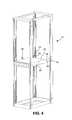
- FIG. 4is a perspective view of a rack with a component fully installed in accordance with the principles of the present invention.
- FIG. 5is a drawing of a rack with an alternate embodiment of a bracket in accordance with the principles of the invention.
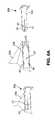
- FIGS. 6A through 6Eshow various embodiments of a locking mechanism between the bracket and the component in accordance with the principles of the present invention.
- FIG. 1is a perspective view of an electronic equipment rack 10 for accepting a plurality of electronic components in vertically stacked slots and showing a rack component 20 in the process of being inserted over two brackets 30 in the rack in accordance with the principles of the present invention.
- the four post rack 10 of the Figuresis exemplary and the invention is not limited to application in such racks. The invention may be applied to other forms of racks as well as cabinets and the like.
- the exemplary component 20is a cable tray, comprising a plurality of slots 26 defined by a plurality of separators 27 .
- a cable traygenerally does not actually contain any electronic or optical components, but merely assists in the separation and routing of cables (not shown in order not to obscure the invention) through the rack 10 .
- the inventionis applicable to any form of component that can be mounted in a rack or cabinet.
- such rackscomprise a base 13 , four posts 15 a , 15 b , 15 c , 15 d rising vertically from the base, and a top 12 . It may also comprise one or more horizontal rails (not shown) to provide structural support for the rack 10 .
- a plurality of components, such as component 20may be installed in the rack 10 , such as routers, servers, cable trays, switching units, etc.
- the posts 15 and/or the railsinclude holes 18 for accepting bolts or other fasteners that may be used to affix components to the rack.
- holes 18will align with holes on the housings of the electronic components so that the components may be affixed to the rack by nuts and bolts passing through the mating holes of the rack and the component (or other fasteners).
- a rack componentsuch as cable tray 20 typically might have flanges 22 extending laterally from its front face 25 , the flanges bearing holes 29 for aligning with the corresponding holes 18 on the rack.
- the components that are installed in racksare of a standardized width, w, corresponding to the width of the rack.
- the depth, dis not necessarily standardized. That is, components of different depths can be installed in a single rack, with deeper components simply extending further towards the rear of the rack than less deep components.
- lighter componentsoften only need to be attached to the rack at their front faces.
- heavier componentsrequire additional support along the sides or towards the rear of the component.
- many rackscontain holes on side or rear rails or on the rear posts 15 c , 15 d of the rack that are designed to align with corresponding holes on the sides, rear or other flanges on the component 20 so that the component can be fastened to and thereby supported by the rack at locations other than the front of the rack.
- one obviouslymust be able to access the rear or sides of the rack after the component has been inserted into the slot in order to attach the component to the rack or otherwise support it from the rear or sides of the rack.
- the inventionprovides a bracket and sleeve system for mounting a component 20 to a rack 10 in which the brackets 30 may be mounted to the rack 10 before the component 20 is placed in the rack so that the installer may attach the brackets to the rear 10 b of the rack by reaching through the front 10 a of the rack 10 (or any other access point) before the component is placed in the rack.
- FIG. 1shows the brackets 30 being mounted flush against the front faces of the rear posts 15 c , 15 d in order to allow the entirety of the brackets, including the flanges 34 , to be seen.
- brackets 30it will be preferable for the installer to attach the brackets 30 to the rear posts 15 c , 15 d with the flange flush against the rear faces of the posts 15 c , 15 d so that the brackets can be installed without the installer needing to reach around from the rear into the rack with a screw driver to attach the brackets 30 to the posts 15 c , 15 d.
- FIG. 2which is a close up view from the rear of the component 20 showing the component engaged with the bracket 30 (disembodied from the rack for clarity)
- the component 20can be slid into the rack 10 from the front of the rack with sleeves 22 (only one of the two sleeves 22 is seen in the close up view of FIG. 2 ) on the component 20 sliding over and engaging the brackets 30 , and with no need to further attach or affix the component 20 to the bracket 30 .
- FIG. 3is a close up view of the exemplary bracket 30 of FIG. 1 , except with holes 36 deleted.
- the bracket 30comprises an arm 32 that will extend horizontally along the depth, d, of the rack 10 when installed on the rack, as shown in FIG. 1 , and a flange 34 bearing holes 36 or slots 38 (or any other reasonable means) for attaching the bracket 30 to the rack 10 .
- the arm 32is sized and shaped to slide into a sleeve on the housing of a component as will be described in more detail herein.
- the component 20is shown with no cables, separators, or electronics contained therein in order not to obscure the invention. However, it should be understood that, typically, the component 20 will be occupied with electronic circuitry, separators, or other components. Furthermore, the top and rear panels of the component are removed in FIG. 2 also in order not to obscure the invention.
- the sleeves 22are located on the internal sides of the opposing lateral side panels 24 of the component (only one side panel 24 and sleeve 22 are visible in the close up view of FIG. 2 ). Alternately, the sleeves can be positioned on the outer sides of the lateral side panels 24 .
- a cable traysuch as illustrated in FIG. 1 normally would not have a rear panel.
- the rear panel of that componentshould be designed to provide spaces between its lateral edges and the lateral side walls 24 through which the arms 32 of the brackets 30 can pass in order to slide into the sleeves 22 .
- the sleeves 22are sized, shaped, and positioned to slidably receive the arms 32 of the brackets 30 therein through the rear openings 22 a of the sleeves.
- the sleevesmay be separate pieces that are attached to the component or may be integrally formed from the panels of the component itself.
- FIG. 4is a similar view to that of FIG. 1 , but showing the component 20 fully inserted into the rack and installed in the brackets 30 .
- the flanges 34 of the brackets 30should be sized, shaped, and positioned relative to the arms 32 so that their holes 36 , slots 38 , or other mounting mechanisms can be attached to the rack 10 so that, when mounted, the arms 32 extend horizontally and parallel to each other along the opposing lateral sides of the rack in the depth direction, d, so that a component 20 bearing the sleeves 22 in accordance with the invention can be slid into the front of the rack with the sleeves 22 sliding over and engaging the arms 32 of the brackets 30 as shown in FIG. 4 .
- the width between the two lateral side panels 24 of the component 20would need to be selected so that the sleeves 22 are in the proper location to engage the brackets 30 as will be described further below.
- the lateral side wallsshould be spaced a little farther apart than if the sleeves were mounted on the external sides of the lateral side walls 24 .
- the length of the arm 32 of the bracketis sufficiently long so that it will be guaranteed to engage the sleeve on a component over at least a portion of the arm's length for components of different depths.
- the sleeves of components of lesser depthwould simply engage a shorter portion of the arm 32 than the sleeves of components of greater depth.
- components of different depthsmay be installed within the same front to back rack spacing using identical brackets.
- the rear end 22 a of the sleeve 22may be flared outwardly in order to facilitate the arm 32 of the bracket entering into the sleeve 22 as the component 20 is being introduced into the rack.
- the far end 39 of the bracket from the flangemay be tapered in one or more axes.
- the bracketsmay be sized and shaped so that the installer's appendages and flesh are much less likely to be trapped between the component, bracket, and/or sleeve via guard surfaces.
- a handlemay be attached to or formed into the rear of the component to facilitate sliding it through the rack opening and through the depth of the rack (for rear entry environments). For instance, a small flange could be formed directly from the rear wall of the component that one could grab and pull on to help move the component rearward, avoiding the need to place one's fingers under or beside the component.
- FIG. 5shows an alternate bracket 30 a designed to be attached to a rack 10 a by bolts extending in the width direction, w, of the rack, rather than the depth direction, d.
- this bracket 30 acomprises a first flange 34 a , like flange 34 of the first embodiment, extending perpendicularly from the rear end of the arm 32 , and a second flange 37 extending perpendicularly from the end of the first flange 34 a .
- This type of designcan be used to mount the bracket 30 a to a rack 10 a or cabinet via either side rails 16 or the rear posts 15 c , 15 d , with bolts extending laterally rather than in the depth direction.
- the bracketcan be affixed to the rack before the component is installed; when there is access to the rear of the rack through the slot in the rack into which the component will be installed.
- an installercan fasten the bracket to the rack by reaching inside of the rack from the front opening into which the component is to be installed without the need for access from the rear or sides of the rack. Then, after the bracket is installed, the component can be slid into the rack through that opening so that the sleeves 22 on the lateral side panels of the component 20 travel over and engage the brackets.
- the front panel of the componentmay then be fixed to the rack by bolts and nuts passing through the holes in the front panel (or front flanges) of the component and mating holes on the front posts 15 a , 15 b of the rack as previously described.
- the bracketswill provide support for the components along the entire portion of the length of the bracket arm that is within the sleeve.
- Ball bearings or other bearingsmay be provided on the bracket arms and/or within the sleeves to facilitate smooth sliding of the bracket arms into the sleeves.
- one or more detent featuresmay be provided on the bracket and/or the sleeve to provide one or more tactile stops for the insertion of the component over the brackets.
- the engagement of the sleeves with the bracketsnot only supports the component, but also provides an inherent centering feature for centering the components correctly in the slots of the rack.
- the sleeve and/or the bracketalso may be coated or entirely formed of a low friction material to ease the sliding of the bracket relative to the sleeve.
- the arms of the bracketsmay comprise multiple pieces and may be telescoping, in the nature of a drawer support.
- an automatic locking mechanismmay be provided for locking the brackets to the component.
- a lever, cam, wedge, jackscrew, collet, or other mechanismmay be included to provide a positive locking mechanism between the bracket and the sleeve (or the component) to enhance the securing of the component to the rack.
- Such mechanismsmay entail a multiple piece mounting bracket with parts that can move relative to each other to effect this locking feature.
- the movement needed to cause lockingmay be a vertical movement, such as in conventional dresser drawers, a lateral movement in the width direction of the rack, or a push-pull movement in the depth direction d of the rack. Any reasonable locking mechanism that does not require manual access to the locking mechanism may be employed.
- a spring-loaded pawl mechanism or jaw mechanismmay be provided inside the sleeve near its proximal end 22 b that engages a mating structure at the far end 39 of the arm of the bracket from the flange such that, when the component is slid onto the bracket in the depth direction, the pawl or jaw engages the mating feature of the end of the bracket, causing the pawl or jaw to open against the spring bias in order to pass over the feature on the arm and then close again behind the feature to affect the locking.
- the locking mechanismalso permits the unlocking of the pawl, jaw, or other mechanism from the feature on the bracket without the need to manually access the locking mechanism.
- the pawls, jaws or other mechanismmay be designed to permit disengagement by pulling the component out in the depth direction with sufficient force to overcome the spring bias.
- the mechanismmay be disengaged by insertion of a tool through a slot in the front face of the component that can engage the locking mechanism and be operated to cause it to unlock from the bracket.
- a button or levermay be provided on or extending from the front face of the component that can be pressed or otherwise operated to manipulate the pawls, jaws or other mechanisms to cause them to release their engagement with the mating features on the brackets.
- the locking mechanismmay be a detent mechanism. For instance, a bump on the side of the bracket near the far end of the bracket from the flange may engage a divot in a narrowed portion of the sleeve near the proximal end of the sleeve.
- the locking mechanism within the sleeve and the bracketmay both be formed of a conductive material, such as a metal, so that the engagement of the bracket with the locking mechanism inside the sleeve further serves the purpose of providing a tool-less grounding method for electrically communing the component to the rack.
- the bracketsmay be adjustable in multiple degrees of freedom (roll, pitch, yaw, depth, height, and/or width) so that a single bracket can be used with different width, height and/or depth racks and/or components and/or to permit adjustment of the brackets relative to each other for purposes of leveling of a component within in a rack.
- the bracketmay be provided with a leveling feature that allows adjustment of the angle of the component in the rack in one or more degrees of freedom including roll, pitch, and yaw.
- the bracket and/or the componentmay be provided with a level indicator, such as silkscreened lines or a spirit bubble to further assist in leveling the component in the rack from front to back as well as side to side.
- the bracket and/or the sleevemay be designed to assist with shock and vibration absorption.
- the inside of the sleevemay be lined with a resilient material 28 that absorbs shock and vibration between the bracket and the component.
- leaf or coil springsmay be provided within the sleeves to provide shock and vibration absorption.
- FIGS. 6A through 6Eillustrate four exemplary locking mechanisms for locking the component to the bracket.
- the bracket 30 bhas a split arm 32 b defining a slit 33 running longitudinally down the center of the arm.
- the slitincludes a carve-out portion 35 .
- the component 20 bincludes a laterally oriented stud 27 within the sleeve 22 b that is wider in diameter than the slit 33 in the arm 32 b .
- the stud 27slides into the slit 33 , forcing the slit to open wider to accept the stud therethrough.
- FIG. 6Aalso illustrates leaf springs 40 inside the sleeve 22 b such as mentioned in the preceding paragraph for providing shock and vibration absorption.
- FIG. 6Billustrates another releasable locking mechanism.
- the arm 32 c of bracket 30 calso is split into two halves 32 c - 1 and 32 c - 2 by a slit 33 a .
- at least the front end of the arm 32 cis slightly wider than the sleeve 22 c when the arm is in an unstressed condition.
- the front ends of the two arm halvesmay be tapered as shown at 41 .
- the tapers 41meet the edges of the sleeve and force the arm halves to squeeze toward each other, narrowing the slit 33 a between them.
- the slit 33 ais wide enough to allow the two arm halves to squeeze together enough to permit the arm 30 c to enter the sleeve 22 c .
- the friction between the arm and the sleevewill serve to lock the arm within the sleeve and allow the arm to be pulled out of the sleeve (or vice versa) only upon application of a sufficient force.
- the required force to insert and remove the arm from the sleeveshould be set by proper selection of materials and slit design to be large enough that the component cannot fall out accidentally, but small enough so that it can be inserted and removed without the need for force greater than can be applied reasonably by a single person.
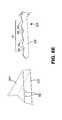
- FIG. 6Cillustrates yet another embodiment in which the sleeve 22 d of component 20 d includes an embossed bump 51 and the bracket 30 d includes an embossed divot 52 .
- the bracketis positioned relative to the sleeve so that the bracket arm 32 d must bend to enter the sleeve 22 d .
- the end of the bracket armmay be curved so as to assure that the arm will initially enter the sleeve without being blocked by the rear edge 54 of the sleeve.
- the bracket 30 dis resilient in the lateral direction as illustrated by arrows 53 so that the bracket will flex to enter the sleeve with the face 55 of the bracket rubbing against the inner face of the sleeve 22 d .
- the arm 32 dwill snap back slightly, thereby providing a detent-type locking of the bump 51 within the divot 52 .
- the bracket 32 dmay be withdrawn in the same manner, i.e., by pulling on the component 20 d with enough force to overcome the frictional engagement of the bump 51 in the divot 52 .
- FIG. 6Dillustrates yet another embodiment quite similar to the embodiment of FIG. 6C except that, instead of an embossed bump, a spring loaded ball 57 is provided in the sleeve 22 e of component 20 e to mate with the divot 52 on the arm 32 d of the bracket 32 d.
- FIG. 6Eshows another embodiment in which the arm 32 f of the bracket 30 f includes a sawtooth pattern 61 on its top edge and one or more pins 62 are disposed within the sleeve 22 f of component 20 f .
- the sleeveis inserted over the bracket until the pin(s) drop into the valley(s) 65 of the sawtooth pattern 61 , thereby providing another form of detent engagement of the bracket 30 f to the component 20 f .
- the componentmay be disengaged from the detents either by pulling on it with sufficient force to cause the pin(s) 62 to ride up the sloped sides 66 of the valleys 65 or by lifting the component 20 f slightly so that the pins 62 rise out of the valleys 65 , and then pulling the component 20 f out.
- the bracketmay be attached to the front of the rack through a slot opening in the rear of the rack with the arm extending from the front of the rack toward the rear of the rack, and the component is slid onto the bracket from the rear of the rack.
- the rackis accessed from the rear and the component is slid into the rack from the rear.
- the principles described hereincan also be applied in situations where the rack is accessed from a side of the rack and the component is slid into the rack sideways.
- the bracketmay be attached to the far side of the rack through a slot opening in the near side of the rack with the arm extending laterally from the far side of the rack toward the near side of the rack, and the component is slid onto the bracket sideways from the near side of the rack to the far side of the rack.
Landscapes
- Engineering & Computer Science (AREA)
- Computer Hardware Design (AREA)
- General Engineering & Computer Science (AREA)
- Microelectronics & Electronic Packaging (AREA)
- Casings For Electric Apparatus (AREA)
- Supply And Installment Of Electrical Components (AREA)
- Connection Of Plates (AREA)
- Drawers Of Furniture (AREA)
Abstract
Description
Claims (16)
Priority Applications (2)
| Application Number | Priority Date | Filing Date | Title |
|---|---|---|---|
| US15/397,465US9699932B2 (en) | 2010-12-10 | 2017-01-03 | Method and apparatus for mounting rack components on racks |
| US15/601,511US9872414B2 (en) | 2010-12-10 | 2017-05-22 | Method and apparatus for mounting rack components on racks |
Applications Claiming Priority (4)
| Application Number | Priority Date | Filing Date | Title |
|---|---|---|---|
| US42174010P | 2010-12-10 | 2010-12-10 | |
| US13/305,872US9326414B2 (en) | 2010-12-10 | 2011-11-29 | Method and apparatus for mounting rack components on racks |
| US15/137,909US9572278B2 (en) | 2010-12-10 | 2016-04-25 | Method and apparatus for mounting rack components on racks |
| US15/397,465US9699932B2 (en) | 2010-12-10 | 2017-01-03 | Method and apparatus for mounting rack components on racks |
Related Parent Applications (1)
| Application Number | Title | Priority Date | Filing Date |
|---|---|---|---|
| US15/137,909ContinuationUS9572278B2 (en) | 2010-12-10 | 2016-04-25 | Method and apparatus for mounting rack components on racks |
Related Child Applications (1)
| Application Number | Title | Priority Date | Filing Date |
|---|---|---|---|
| US15/601,511ContinuationUS9872414B2 (en) | 2010-12-10 | 2017-05-22 | Method and apparatus for mounting rack components on racks |
Publications (2)
| Publication Number | Publication Date |
|---|---|
| US20170118862A1 US20170118862A1 (en) | 2017-04-27 |
| US9699932B2true US9699932B2 (en) | 2017-07-04 |
Family
ID=45406424
Family Applications (4)
| Application Number | Title | Priority Date | Filing Date |
|---|---|---|---|
| US13/305,872Active2032-08-14US9326414B2 (en) | 2010-12-10 | 2011-11-29 | Method and apparatus for mounting rack components on racks |
| US15/137,909ActiveUS9572278B2 (en) | 2010-12-10 | 2016-04-25 | Method and apparatus for mounting rack components on racks |
| US15/397,465ActiveUS9699932B2 (en) | 2010-12-10 | 2017-01-03 | Method and apparatus for mounting rack components on racks |
| US15/601,511ActiveUS9872414B2 (en) | 2010-12-10 | 2017-05-22 | Method and apparatus for mounting rack components on racks |
Family Applications Before (2)
| Application Number | Title | Priority Date | Filing Date |
|---|---|---|---|
| US13/305,872Active2032-08-14US9326414B2 (en) | 2010-12-10 | 2011-11-29 | Method and apparatus for mounting rack components on racks |
| US15/137,909ActiveUS9572278B2 (en) | 2010-12-10 | 2016-04-25 | Method and apparatus for mounting rack components on racks |
Family Applications After (1)
| Application Number | Title | Priority Date | Filing Date |
|---|---|---|---|
| US15/601,511ActiveUS9872414B2 (en) | 2010-12-10 | 2017-05-22 | Method and apparatus for mounting rack components on racks |
Country Status (7)
| Country | Link |
|---|---|
| US (4) | US9326414B2 (en) |
| EP (2) | EP3154322B1 (en) |
| CA (1) | CA2760708C (en) |
| ES (2) | ES2894076T3 (en) |
| HU (1) | HUE033284T2 (en) |
| MX (1) | MX2011013359A (en) |
| PL (1) | PL2464205T3 (en) |
Cited By (1)
| Publication number | Priority date | Publication date | Assignee | Title |
|---|---|---|---|---|
| US10149402B1 (en)* | 2015-09-30 | 2018-12-04 | EMC IP Holding Company LLC | Rack-mountable IT device |
Families Citing this family (30)
| Publication number | Priority date | Publication date | Assignee | Title |
|---|---|---|---|---|
| US9326414B2 (en) | 2010-12-10 | 2016-04-26 | Commscope Technologies Llc | Method and apparatus for mounting rack components on racks |
| TWM428616U (en)* | 2011-12-27 | 2012-05-01 | Hon Hai Prec Ind Co Ltd | Fixing structure of electronic device |
| CN107037855B (en)* | 2015-07-14 | 2020-06-26 | 纬创资通(中山)有限公司 | Server external member and system capable of simultaneously bearing multiple hard disks and server slide rail |
| US10077551B2 (en)* | 2015-10-05 | 2018-09-18 | Illinois Tool Works Inc. | Joint edge assembly and method for forming joint in offset position |
| TWI565396B (en)* | 2015-11-04 | 2017-01-01 | 川湖科技股份有限公司 | Slide rail assembly |
| CN106714499A (en)* | 2015-11-17 | 2017-05-24 | 川湖科技股份有限公司 | Sliding rail assembly |
| CN105425919B (en)* | 2015-12-17 | 2019-04-16 | 英业达科技有限公司 | A kind of server system and its position-limit mechanism of application |
| US9913396B2 (en)* | 2015-12-22 | 2018-03-06 | Quanta Computer Inc. | Reverse mount apparatus for a rack-mounted systems |
| CN113876129B (en)* | 2016-04-22 | 2023-01-31 | 川湖科技股份有限公司 | Bracket device |
| US10485132B2 (en) | 2016-05-27 | 2019-11-19 | Hewlett Packard Enterprise Development Lp | Rail kits |
| US10034407B2 (en)* | 2016-07-22 | 2018-07-24 | Intel Corporation | Storage sled for a data center |
| TWI623288B (en)* | 2016-09-24 | 2018-05-11 | 川湖科技股份有限公司 | Rail mounting fitting assembly for rack |
| CN106535552B (en)* | 2016-12-13 | 2022-09-23 | 无锡海达尔精密滑轨股份有限公司 | Rear end of server rack slide rail exempts from instrument installing support |
| US10117348B2 (en)* | 2017-03-09 | 2018-10-30 | International Business Machines Corporation | Cable management bracket |
| US10356931B1 (en)* | 2017-05-26 | 2019-07-16 | King Slide Works Co., Ltd. | Rack mounting system |
| US10363978B2 (en)* | 2017-07-14 | 2019-07-30 | Dell Products L.P. | Split chassis system |
| CN110362161B (en)* | 2018-04-09 | 2022-12-27 | 富联精密电子(天津)有限公司 | Plug-in device, case adopting plug-in device and electronic device |
| US10932387B2 (en)* | 2018-05-25 | 2021-02-23 | Cisco Technology, Inc. | Quick release for online insertion and removal of a module in a distributed network system |
| US10606011B2 (en) | 2018-06-20 | 2020-03-31 | Panduit Corp. | Universal expandable cable management bracket |
| US12167561B2 (en) | 2019-03-08 | 2024-12-10 | Commscope Technologies Llc | Toolless panel mounting system |
| US10709032B1 (en)* | 2019-09-24 | 2020-07-07 | International Business Machines Corporation | Datacenter rack and removable tray |
| US11372180B2 (en)* | 2020-01-31 | 2022-06-28 | Ciena Corporation | Modular networking hardware platform |
| US11313434B2 (en) | 2020-06-30 | 2022-04-26 | Rolls-Royce North American Technologies, Inc. | Shock absorption bracket |
| CN111787748A (en)* | 2020-08-09 | 2020-10-16 | 苏州浪潮智能科技有限公司 | A slide rail structure that prevents the server from falling and tilting |
| EP4050979A1 (en)* | 2021-02-26 | 2022-08-31 | Ovh | Rack system and method for positioning a data center rack |
| US11765845B2 (en)* | 2021-07-28 | 2023-09-19 | Nanning Fulian Fugui Precision Industrial Co., Ltd. | Electronic apparatus with mounting mechanism |
| US11844190B2 (en)* | 2021-09-20 | 2023-12-12 | Dell Products L.P. | Top of stack safety rail |
| ES1290533Y (en)* | 2022-01-21 | 2022-08-03 | Egana Arrieta Joseba | Exhibitor system for coupling to visual communication products |
| WO2023154175A1 (en)* | 2022-02-10 | 2023-08-17 | Commscope Technologies Llc | Asymmetric brackets that facilitate passive cooling of network switches |
| TWI828564B (en)* | 2023-03-23 | 2024-01-01 | 明泰科技股份有限公司 | Ear stand assembly for easy installation |
Citations (24)
| Publication number | Priority date | Publication date | Assignee | Title |
|---|---|---|---|---|
| US5571256A (en) | 1994-10-25 | 1996-11-05 | Compaq Computer Corporation | Server drawer slide mount apparatus for a rack-mounted computer system |
| US5626406A (en) | 1995-02-02 | 1997-05-06 | Glenayre Electronics, Inc. | Integrated chassis slide assembly |
| US6123303A (en) | 1998-04-24 | 2000-09-26 | Huang; Robert C. | Retractable bracket structure |
| US20010037985A1 (en) | 1998-07-31 | 2001-11-08 | George Jordan | Computer component rack mounting arrangement |
| US20010040203A1 (en) | 2000-03-17 | 2001-11-15 | Brock Patty J. | Computer server mounting apparatus |
| US20020043508A1 (en) | 2000-10-13 | 2002-04-18 | Lewis Kevin William | Support bracket |
| US20040120106A1 (en) | 2002-12-20 | 2004-06-24 | Searby Tom J | Transformable computer and system and method incorporating same |
| US20040120123A1 (en) | 2002-12-20 | 2004-06-24 | Mayer David W. | Multi-configurable telecommunications rack mounting system and method incorporating same |
| US20040227441A1 (en) | 2003-05-14 | 2004-11-18 | Yu-Jiun Wang | Rail assembly for attaching server to cabinet |
| US20050285492A1 (en) | 2004-06-28 | 2005-12-29 | Tatung Co., Ltd. | Sliding rail mounting structure |
| US7014051B2 (en) | 2002-05-20 | 2006-03-21 | Sun Microsystems, Inc. | Apparatus and method for mounting a component in a rack |
| US7086546B2 (en) | 2003-02-27 | 2006-08-08 | Meier Roger L | Clamp |
| US20080073469A1 (en)* | 2006-09-26 | 2008-03-27 | Central Industrial Supply Company | Mounting bracket for square hole racks and round hole racks |
| US20080217271A1 (en) | 2005-02-19 | 2008-09-11 | Visplay International Ag | Device For Suspending Articles or For Holding a Shelf, and Structure Provided Therewith |
| US20080230496A1 (en)* | 2007-03-20 | 2008-09-25 | Gregory Henderson | Universal rack mount mechanism |
| US20100007255A1 (en) | 2008-07-08 | 2010-01-14 | Chi-Tsun Cheng | Rail set assembly for a machine casing of the industrial computer |
| US7703734B2 (en) | 2007-12-27 | 2010-04-27 | King Slide Works Co., Ltd. | Slide mounting bracket structure |
| US20100200523A1 (en) | 2009-02-09 | 2010-08-12 | Dell Products L.P. | Tool-less Rack Mounting Apparatus and Systems |
| US7937914B2 (en) | 2006-08-02 | 2011-05-10 | The Glad Products Company | Device and method for evacuating storage bag |
| US8348210B1 (en) | 2011-11-29 | 2013-01-08 | Chia-Hung Lee | Positioning device for shelves |
| US8371454B2 (en)* | 2008-09-25 | 2013-02-12 | King Slide Works Co., Ltd. | Bracket assembly for a rack |
| US8408506B2 (en) | 2010-02-05 | 2013-04-02 | Hong Fu Jin Precision Industry (Shenzhen) Co., Ltd. | Mounting appratus for slide rail |
| US8596471B2 (en) | 2010-09-24 | 2013-12-03 | King Slide Works Co., Ltd. | Mounting bracket |
| US9326414B2 (en) | 2010-12-10 | 2016-04-26 | Commscope Technologies Llc | Method and apparatus for mounting rack components on racks |
Family Cites Families (2)
| Publication number | Priority date | Publication date | Assignee | Title |
|---|---|---|---|---|
| US20070247044A1 (en)* | 2006-04-25 | 2007-10-25 | International Business Machines Corporation | Self-Locating Rear Mount System and Method for Rack Mountable Equipment |
| CN102548331B (en)* | 2010-12-09 | 2016-02-03 | 青岛橡胶谷知识产权有限公司 | Device for fixing slide rail |
- 2011
- 2011-11-29USUS13/305,872patent/US9326414B2/enactiveActive
- 2011-12-06CACA2760708Apatent/CA2760708C/enactiveActive
- 2011-12-07EPEP16197273.2Apatent/EP3154322B1/enactiveActive
- 2011-12-07PLPL11192348Tpatent/PL2464205T3/enunknown
- 2011-12-07EPEP11192348.8Apatent/EP2464205B1/enactiveActive
- 2011-12-07HUHUE11192348Apatent/HUE033284T2/enunknown
- 2011-12-07ESES16197273Tpatent/ES2894076T3/enactiveActive
- 2011-12-07ESES11192348.8Tpatent/ES2613062T3/enactiveActive
- 2011-12-09MXMX2011013359Apatent/MX2011013359A/enactiveIP Right Grant
- 2016
- 2016-04-25USUS15/137,909patent/US9572278B2/enactiveActive
- 2017
- 2017-01-03USUS15/397,465patent/US9699932B2/enactiveActive
- 2017-05-22USUS15/601,511patent/US9872414B2/enactiveActive
Patent Citations (25)
| Publication number | Priority date | Publication date | Assignee | Title |
|---|---|---|---|---|
| US5571256A (en) | 1994-10-25 | 1996-11-05 | Compaq Computer Corporation | Server drawer slide mount apparatus for a rack-mounted computer system |
| US5626406A (en) | 1995-02-02 | 1997-05-06 | Glenayre Electronics, Inc. | Integrated chassis slide assembly |
| US6123303A (en) | 1998-04-24 | 2000-09-26 | Huang; Robert C. | Retractable bracket structure |
| US20010037985A1 (en) | 1998-07-31 | 2001-11-08 | George Jordan | Computer component rack mounting arrangement |
| US20010040203A1 (en) | 2000-03-17 | 2001-11-15 | Brock Patty J. | Computer server mounting apparatus |
| US20020043508A1 (en) | 2000-10-13 | 2002-04-18 | Lewis Kevin William | Support bracket |
| US7014051B2 (en) | 2002-05-20 | 2006-03-21 | Sun Microsystems, Inc. | Apparatus and method for mounting a component in a rack |
| US20040120106A1 (en) | 2002-12-20 | 2004-06-24 | Searby Tom J | Transformable computer and system and method incorporating same |
| US20040120123A1 (en) | 2002-12-20 | 2004-06-24 | Mayer David W. | Multi-configurable telecommunications rack mounting system and method incorporating same |
| US7086546B2 (en) | 2003-02-27 | 2006-08-08 | Meier Roger L | Clamp |
| US20040227441A1 (en) | 2003-05-14 | 2004-11-18 | Yu-Jiun Wang | Rail assembly for attaching server to cabinet |
| US20050285492A1 (en) | 2004-06-28 | 2005-12-29 | Tatung Co., Ltd. | Sliding rail mounting structure |
| US20080217271A1 (en) | 2005-02-19 | 2008-09-11 | Visplay International Ag | Device For Suspending Articles or For Holding a Shelf, and Structure Provided Therewith |
| US7937914B2 (en) | 2006-08-02 | 2011-05-10 | The Glad Products Company | Device and method for evacuating storage bag |
| US20080073469A1 (en)* | 2006-09-26 | 2008-03-27 | Central Industrial Supply Company | Mounting bracket for square hole racks and round hole racks |
| US20080230496A1 (en)* | 2007-03-20 | 2008-09-25 | Gregory Henderson | Universal rack mount mechanism |
| US7703734B2 (en) | 2007-12-27 | 2010-04-27 | King Slide Works Co., Ltd. | Slide mounting bracket structure |
| US20100007255A1 (en) | 2008-07-08 | 2010-01-14 | Chi-Tsun Cheng | Rail set assembly for a machine casing of the industrial computer |
| US8292382B2 (en) | 2008-07-08 | 2012-10-23 | Lif J. K. Corporation | Rail set assembly for a machine casing of the industrial computer |
| US8371454B2 (en)* | 2008-09-25 | 2013-02-12 | King Slide Works Co., Ltd. | Bracket assembly for a rack |
| US20100200523A1 (en) | 2009-02-09 | 2010-08-12 | Dell Products L.P. | Tool-less Rack Mounting Apparatus and Systems |
| US8408506B2 (en) | 2010-02-05 | 2013-04-02 | Hong Fu Jin Precision Industry (Shenzhen) Co., Ltd. | Mounting appratus for slide rail |
| US8596471B2 (en) | 2010-09-24 | 2013-12-03 | King Slide Works Co., Ltd. | Mounting bracket |
| US9326414B2 (en) | 2010-12-10 | 2016-04-26 | Commscope Technologies Llc | Method and apparatus for mounting rack components on racks |
| US8348210B1 (en) | 2011-11-29 | 2013-01-08 | Chia-Hung Lee | Positioning device for shelves |
Non-Patent Citations (2)
| Title |
|---|
| European Search Report for Application No. 11192348.8 mailed Sep. 17, 2014, 5 pp. |
| Extended European Search Report for Application No. 16197273.2 mailed Mar. 23, 2017. |
Cited By (1)
| Publication number | Priority date | Publication date | Assignee | Title |
|---|---|---|---|---|
| US10149402B1 (en)* | 2015-09-30 | 2018-12-04 | EMC IP Holding Company LLC | Rack-mountable IT device |
Also Published As
| Publication number | Publication date |
|---|---|
| US20170118862A1 (en) | 2017-04-27 |
| MX2011013359A (en) | 2013-06-10 |
| EP3154322A2 (en) | 2017-04-12 |
| EP2464205A3 (en) | 2014-10-15 |
| US20160286681A1 (en) | 2016-09-29 |
| HUE033284T2 (en) | 2017-11-28 |
| CA2760708C (en) | 2019-01-08 |
| ES2894076T3 (en) | 2022-02-11 |
| EP2464205A2 (en) | 2012-06-13 |
| US9572278B2 (en) | 2017-02-14 |
| ES2613062T3 (en) | 2017-05-22 |
| US20120145874A1 (en) | 2012-06-14 |
| PL2464205T3 (en) | 2017-09-29 |
| EP2464205B1 (en) | 2016-11-09 |
| CA2760708A1 (en) | 2012-06-10 |
| US9872414B2 (en) | 2018-01-16 |
| EP3154322A3 (en) | 2017-04-26 |
| US9326414B2 (en) | 2016-04-26 |
| US20170257971A1 (en) | 2017-09-07 |
| EP3154322B1 (en) | 2021-07-21 |
Similar Documents
| Publication | Publication Date | Title |
|---|---|---|
| US9872414B2 (en) | Method and apparatus for mounting rack components on racks | |
| US11439034B2 (en) | Uniform equipment mounting system | |
| US7012808B2 (en) | Multi-configurable telecommunications rack mounting system and method incorporating same | |
| US7731524B2 (en) | Blind docking electrical connector | |
| US6373707B1 (en) | Module mounting slide clamp mechanism | |
| US20080217274A1 (en) | Toolless Rack Mounting Rail Installation Latch | |
| US7281694B2 (en) | Mounting bracket | |
| US6422399B1 (en) | Rack system and method having tool-less releasable arm assembly | |
| US9370119B2 (en) | Sliding rack-mountable rails for rack-mountable components | |
| US7975860B2 (en) | Toolless rail mounting for a computer system rack | |
| US9629276B2 (en) | Adjustable snap-in rail assembly for storage rack | |
| WO2006012389A1 (en) | Front access punch down patch panel | |
| US20120212893A1 (en) | Server Retention Mechanism | |
| US20160338217A1 (en) | Connectors To Secure Multiple Rails In A Server Rack | |
| US7810653B2 (en) | Apparatus and method for mounting a device to a rack system | |
| EP3361297A1 (en) | Optical connectors with positions | |
| CN101299912B (en) | Fastening system for fastening a plate within an enclosure | |
| US9030810B2 (en) | Rack structure-mounted power distribution unit | |
| US6481809B1 (en) | Sliding module for computer components | |
| US20190121046A1 (en) | Method of securing fiber optic cassettes allowing for tool-less insertion and extraction | |
| US20100308189A1 (en) | Latching System for Multiple Nodes of a Computer System |
Legal Events
| Date | Code | Title | Description |
|---|---|---|---|
| STCF | Information on status: patent grant | Free format text:PATENTED CASE | |
| AS | Assignment | Owner name:WILMINGTON TRUST, NATIONAL ASSOCIATION, AS COLLATE Free format text:PATENT SECURITY AGREEMENT;ASSIGNOR:COMMSCOPE TECHNOLOGIES LLC;REEL/FRAME:049892/0051 Effective date:20190404 Owner name:JPMORGAN CHASE BANK, N.A., NEW YORK Free format text:TERM LOAN SECURITY AGREEMENT;ASSIGNORS:COMMSCOPE, INC. OF NORTH CAROLINA;COMMSCOPE TECHNOLOGIES LLC;ARRIS ENTERPRISES LLC;AND OTHERS;REEL/FRAME:049905/0504 Effective date:20190404 Owner name:JPMORGAN CHASE BANK, N.A., NEW YORK Free format text:ABL SECURITY AGREEMENT;ASSIGNORS:COMMSCOPE, INC. OF NORTH CAROLINA;COMMSCOPE TECHNOLOGIES LLC;ARRIS ENTERPRISES LLC;AND OTHERS;REEL/FRAME:049892/0396 Effective date:20190404 Owner name:WILMINGTON TRUST, NATIONAL ASSOCIATION, AS COLLATERAL AGENT, CONNECTICUT Free format text:PATENT SECURITY AGREEMENT;ASSIGNOR:COMMSCOPE TECHNOLOGIES LLC;REEL/FRAME:049892/0051 Effective date:20190404 | |
| MAFP | Maintenance fee payment | Free format text:PAYMENT OF MAINTENANCE FEE, 4TH YEAR, LARGE ENTITY (ORIGINAL EVENT CODE: M1551); ENTITY STATUS OF PATENT OWNER: LARGE ENTITY Year of fee payment:4 | |
| AS | Assignment | Owner name:WILMINGTON TRUST, DELAWARE Free format text:SECURITY INTEREST;ASSIGNORS:ARRIS SOLUTIONS, INC.;ARRIS ENTERPRISES LLC;COMMSCOPE TECHNOLOGIES LLC;AND OTHERS;REEL/FRAME:060752/0001 Effective date:20211115 | |
| AS | Assignment | Owner name:APOLLO ADMINISTRATIVE AGENCY LLC, NEW YORK Free format text:SECURITY INTEREST;ASSIGNORS:ARRIS ENTERPRISES LLC;COMMSCOPE TECHNOLOGIES LLC;COMMSCOPE INC., OF NORTH CAROLINA;AND OTHERS;REEL/FRAME:069889/0114 Effective date:20241217 | |
| AS | Assignment | Owner name:RUCKUS WIRELESS, LLC (F/K/A RUCKUS WIRELESS, INC.), NORTH CAROLINA Free format text:RELEASE OF SECURITY INTEREST AT REEL/FRAME 049905/0504;ASSIGNOR:JPMORGAN CHASE BANK, N.A., AS COLLATERAL AGENT;REEL/FRAME:071477/0255 Effective date:20241217 Owner name:COMMSCOPE TECHNOLOGIES LLC, NORTH CAROLINA Free format text:RELEASE OF SECURITY INTEREST AT REEL/FRAME 049905/0504;ASSIGNOR:JPMORGAN CHASE BANK, N.A., AS COLLATERAL AGENT;REEL/FRAME:071477/0255 Effective date:20241217 Owner name:COMMSCOPE, INC. OF NORTH CAROLINA, NORTH CAROLINA Free format text:RELEASE OF SECURITY INTEREST AT REEL/FRAME 049905/0504;ASSIGNOR:JPMORGAN CHASE BANK, N.A., AS COLLATERAL AGENT;REEL/FRAME:071477/0255 Effective date:20241217 Owner name:ARRIS SOLUTIONS, INC., NORTH CAROLINA Free format text:RELEASE OF SECURITY INTEREST AT REEL/FRAME 049905/0504;ASSIGNOR:JPMORGAN CHASE BANK, N.A., AS COLLATERAL AGENT;REEL/FRAME:071477/0255 Effective date:20241217 Owner name:ARRIS TECHNOLOGY, INC., NORTH CAROLINA Free format text:RELEASE OF SECURITY INTEREST AT REEL/FRAME 049905/0504;ASSIGNOR:JPMORGAN CHASE BANK, N.A., AS COLLATERAL AGENT;REEL/FRAME:071477/0255 Effective date:20241217 Owner name:ARRIS ENTERPRISES LLC (F/K/A ARRIS ENTERPRISES, INC.), NORTH CAROLINA Free format text:RELEASE OF SECURITY INTEREST AT REEL/FRAME 049905/0504;ASSIGNOR:JPMORGAN CHASE BANK, N.A., AS COLLATERAL AGENT;REEL/FRAME:071477/0255 Effective date:20241217 | |
| MAFP | Maintenance fee payment | Free format text:PAYMENT OF MAINTENANCE FEE, 8TH YEAR, LARGE ENTITY (ORIGINAL EVENT CODE: M1552); ENTITY STATUS OF PATENT OWNER: LARGE ENTITY Year of fee payment:8 |