US9699680B2 - Wireless local area network receiver and associated method - Google Patents
Wireless local area network receiver and associated methodDownload PDFInfo
- Publication number
- US9699680B2 US9699680B2US14/318,237US201414318237AUS9699680B2US 9699680 B2US9699680 B2US 9699680B2US 201414318237 AUS201414318237 AUS 201414318237AUS 9699680 B2US9699680 B2US 9699680B2
- Authority
- US
- United States
- Prior art keywords
- local area
- area network
- wireless local
- access point
- real time
- Prior art date
- Legal status (The legal status is an assumption and is not a legal conclusion. Google has not performed a legal analysis and makes no representation as to the accuracy of the status listed.)
- Active, expires
Links
- 238000000034methodMethods0.000titleclaimsdescription14
- 238000012545processingMethods0.000claimsabstractdescription24
- 230000005540biological transmissionEffects0.000claimsdescription15
- 230000008569processEffects0.000claimsdescription5
- 230000004069differentiationEffects0.000claimsdescription4
- 230000015572biosynthetic processEffects0.000claims1
- 230000006854communicationEffects0.000description25
- 238000004891communicationMethods0.000description21
- 238000001514detection methodMethods0.000description20
- 238000001228spectrumMethods0.000description8
- 230000007480spreadingEffects0.000description8
- 230000008901benefitEffects0.000description6
- 238000005070samplingMethods0.000description6
- 238000010586diagramMethods0.000description5
- 238000009826distributionMethods0.000description4
- 230000009977dual effectEffects0.000description4
- 230000006870functionEffects0.000description4
- 230000004048modificationEffects0.000description4
- 238000012986modificationMethods0.000description4
- 230000000694effectsEffects0.000description3
- 238000005516engineering processMethods0.000description3
- 238000001914filtrationMethods0.000description3
- 230000000875corresponding effectEffects0.000description2
- 230000003111delayed effectEffects0.000description2
- 238000003708edge detectionMethods0.000description2
- 238000005259measurementMethods0.000description2
- 230000007246mechanismEffects0.000description2
- 238000013459approachMethods0.000description1
- 230000003190augmentative effectEffects0.000description1
- 238000004364calculation methodMethods0.000description1
- 238000006243chemical reactionMethods0.000description1
- 230000001276controlling effectEffects0.000description1
- 230000002596correlated effectEffects0.000description1
- 230000008878couplingEffects0.000description1
- 238000010168coupling processMethods0.000description1
- 238000005859coupling reactionMethods0.000description1
- 230000001066destructive effectEffects0.000description1
- 230000007274generation of a signal involved in cell-cell signalingEffects0.000description1
- 230000010354integrationEffects0.000description1
- 230000002452interceptive effectEffects0.000description1
- 239000011159matrix materialSubstances0.000description1
- 230000000116mitigating effectEffects0.000description1
- 238000005192partitionMethods0.000description1
- 230000010363phase shiftEffects0.000description1
- 238000000638solvent extractionMethods0.000description1
- 238000009827uniform distributionMethods0.000description1
Images


Classifications
- H—ELECTRICITY
- H04—ELECTRIC COMMUNICATION TECHNIQUE
- H04W—WIRELESS COMMUNICATION NETWORKS
- H04W24/00—Supervisory, monitoring or testing arrangements
- H04W24/10—Scheduling measurement reports ; Arrangements for measurement reports
- H—ELECTRICITY
- H04—ELECTRIC COMMUNICATION TECHNIQUE
- H04B—TRANSMISSION
- H04B1/00—Details of transmission systems, not covered by a single one of groups H04B3/00 - H04B13/00; Details of transmission systems not characterised by the medium used for transmission
- H04B1/38—Transceivers, i.e. devices in which transmitter and receiver form a structural unit and in which at least one part is used for functions of transmitting and receiving
- H04B1/40—Circuits
- H04B1/403—Circuits using the same oscillator for generating both the transmitter frequency and the receiver local oscillator frequency
- H04B1/406—Circuits using the same oscillator for generating both the transmitter frequency and the receiver local oscillator frequency with more than one transmission mode, e.g. analog and digital modes
- H—ELECTRICITY
- H04—ELECTRIC COMMUNICATION TECHNIQUE
- H04W—WIRELESS COMMUNICATION NETWORKS
- H04W84/00—Network topologies
- H04W84/02—Hierarchically pre-organised networks, e.g. paging networks, cellular networks, WLAN [Wireless Local Area Network] or WLL [Wireless Local Loop]
- H04W84/10—Small scale networks; Flat hierarchical networks
- H04W84/12—WLAN [Wireless Local Area Networks]
- H—ELECTRICITY
- H04—ELECTRIC COMMUNICATION TECHNIQUE
- H04W—WIRELESS COMMUNICATION NETWORKS
- H04W88/00—Devices specially adapted for wireless communication networks, e.g. terminals, base stations or access point devices
- H04W88/08—Access point devices
- H—ELECTRICITY
- H04—ELECTRIC COMMUNICATION TECHNIQUE
- H04W—WIRELESS COMMUNICATION NETWORKS
- H04W64/00—Locating users or terminals or network equipment for network management purposes, e.g. mobility management
Definitions
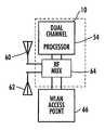
- This inventionrelates to the field of wireless local area networks (WLAN's), and more particularly, this invention relates to real-time location systems and WLAN's.
- WLAN'swireless local area networks
- a wireless local area networkincludes a server and receiver in communication with the server as a network client.
- the receiverincludes a radio frequency (RF) front-end circuit that receives wireless signals from the mobile nodes within the WLAN and detects baseband signals.
- RFradio frequency
- a signal waveform detectoris connected to the RF front-end circuit for edge detecting a signal waveform and generating a trigger signal indicative of the modulation type, data format and time-of-arrival (TOA) information of a desired signal to be captured.
- a baseband processoris connected to the RF front-end circuit and the signal waveform detector and receives the trigger signal from the signal waveform detector and captures the desired signal.
- a system controlleris connected to the baseband processor and configures the baseband processor for processing the desired signal and obtaining message data and signal metrics that are transferred to the system controller to be communicated outbound from the receiver to the server.
- a media access control (MAC) deviceis connected between the system controller and server.
- a TOA processoris connected to the baseband processor and receives the TOA information and generates the time stamp for the desired signal.
- the TOA processorcan be operative for processing TOA information when the receiver is part of a geometric array of network nodes and determine first-to-arrive signals based on a common network timing signal and conduct differentiation of the first-to-arrive signals to locate a desired wireless node.
- FIG. 2is a block diagram of an example of a diversity antenna for the receiver in accordance with a non-limiting example of the present invention.
- FIG. 3is a block diagram of an active antenna for the receiver in accordance with another non-limiting example of the present invention.
- FIG. 4is a high-level block diagram of one example of the circuit architecture that can be modified for use as part of a processor for determining first-to-arrive signals.
- the RF antenna 12can be a single frequency or multi-band antenna.
- Various other wireless nodesare illustrated as part of the WLAN.
- a configurable RF front-end circuit 14can also be single frequency or multi-band for receiving multiple frequencies.
- the RF front-end circuit 14is configured for baseband detection 16 , which can be either a full or partial bandwidth to constrain the number of detected signals.
- the matched filter correlatorsmay be sized and clocked to provide on the order of 4 ⁇ 10 6 correlations per epoch.
- the correlation processing architectureeffectively functions as a matched filter, continuously looking for a match between the reference spreading code sequence and the contents of the incoming signal.
- Each correlation output port 328is compared with a prescribed threshold that is adaptively established by a set of ‘on-demand’ or ‘as needed’ digital processing units 340 - 1 , 340 - 2 , . . . , 340 -K.
- One of the correlator outputs 328has a summation value exceeding the threshold, which delayed version of the PN spreading sequence is effectively aligned (to within half a chip time) with the incoming signal.
- WLANwireless local area network
- the assumptionis that the wireless communications signal, as a spread spectrum signal, has a high signal-to-noise ratio with reasonable power levels.
- the leading edge of this communication signalcan be detected to a high accuracy and this information used with the algorithms as described before to provide relative time of arrival information for subsequent processing.
- a timing signalfrom a known location.
- Other component locationswould have to be known, of course.
- some wireless local area network (WLAN) transmittershave known locations to enable the use of the algorithm when an access point base station or mobile station location is known.
Landscapes
- Engineering & Computer Science (AREA)
- Computer Networks & Wireless Communication (AREA)
- Signal Processing (AREA)
- Mobile Radio Communication Systems (AREA)
- Burglar Alarm Systems (AREA)
- Selective Calling Equipment (AREA)
Abstract
Description
Claims (18)
Priority Applications (1)
| Application Number | Priority Date | Filing Date | Title |
|---|---|---|---|
| US14/318,237US9699680B2 (en) | 2006-03-31 | 2014-06-27 | Wireless local area network receiver and associated method |
Applications Claiming Priority (3)
| Application Number | Priority Date | Filing Date | Title |
|---|---|---|---|
| US78788506P | 2006-03-31 | 2006-03-31 | |
| US11/692,250US8768343B2 (en) | 2006-03-31 | 2007-03-28 | Wireless local area network receiver and associated method |
| US14/318,237US9699680B2 (en) | 2006-03-31 | 2014-06-27 | Wireless local area network receiver and associated method |
Related Parent Applications (1)
| Application Number | Title | Priority Date | Filing Date |
|---|---|---|---|
| US11/692,250ContinuationUS8768343B2 (en) | 2006-03-31 | 2007-03-28 | Wireless local area network receiver and associated method |
Publications (2)
| Publication Number | Publication Date |
|---|---|
| US20150117422A1 US20150117422A1 (en) | 2015-04-30 |
| US9699680B2true US9699680B2 (en) | 2017-07-04 |
Family
ID=38514203
Family Applications (2)
| Application Number | Title | Priority Date | Filing Date |
|---|---|---|---|
| US11/692,250Active2032-02-16US8768343B2 (en) | 2006-03-31 | 2007-03-28 | Wireless local area network receiver and associated method |
| US14/318,237Active2027-05-20US9699680B2 (en) | 2006-03-31 | 2014-06-27 | Wireless local area network receiver and associated method |
Family Applications Before (1)
| Application Number | Title | Priority Date | Filing Date |
|---|---|---|---|
| US11/692,250Active2032-02-16US8768343B2 (en) | 2006-03-31 | 2007-03-28 | Wireless local area network receiver and associated method |
Country Status (5)
| Country | Link |
|---|---|
| US (2) | US8768343B2 (en) |
| EP (2) | EP2005655B1 (en) |
| AT (1) | ATE484902T1 (en) |
| DE (1) | DE602007009813D1 (en) |
| WO (1) | WO2007126819A1 (en) |
Cited By (1)
| Publication number | Priority date | Publication date | Assignee | Title |
|---|---|---|---|---|
| US10304304B1 (en) | 2015-03-02 | 2019-05-28 | Enovate Medical, Llc | Asset management using an asset tag device |
Families Citing this family (17)
| Publication number | Priority date | Publication date | Assignee | Title |
|---|---|---|---|---|
| US8768343B2 (en) | 2006-03-31 | 2014-07-01 | Zebra Enterprise Solutions Corp | Wireless local area network receiver and associated method |
| US9362976B2 (en) | 2006-04-26 | 2016-06-07 | Zih Corp. | Wireless local area network system and receiver adapted for use thereof and associated method |
| US8892065B2 (en)* | 2006-04-26 | 2014-11-18 | Zebra Enterprise Solutions Corp. | Method, apparatus, and computer program product for wireless signal storage with signal recognition detection triggering |
| CA2706695C (en) | 2006-12-04 | 2019-04-30 | Lynx System Developers, Inc. | Autonomous systems and methods for still and moving picture production |
| GB0802126D0 (en)* | 2008-02-05 | 2008-03-12 | Level 5 Networks Inc | Scalable sockets |
| EP2405977B1 (en) | 2009-03-13 | 2020-08-12 | Isolynx, LLC | System and methods for providing performance feedback |
| CA3042453C (en) | 2010-01-05 | 2020-11-10 | Isolynx, Llc | Systems and methods for analyzing event data |
| US8786495B2 (en) | 2010-07-14 | 2014-07-22 | Zebra Enterprise Solutions Corp. | Frequency channel diversity for real-time locating systems, methods, and computer program products |
| NZ718566A (en) | 2010-11-19 | 2017-10-27 | Isolynx Llc | Associative object tracking systems and methods |
| EP2681582B1 (en) | 2011-03-04 | 2023-08-09 | Zebra Technologies Corporation | Method, apparatus, and computer program product for processing received signals for locating |
| US9081076B2 (en) | 2012-11-12 | 2015-07-14 | Isolynx, Llc | System and method for object tracking anti-jitter filtering |
| CN104813737A (en)* | 2013-01-03 | 2015-07-29 | 英特尔公司 | Apparatus, system and method for triggering wireless local area network (WLAN) actions of user equipment (UE) |
| US9439099B2 (en) | 2013-10-14 | 2016-09-06 | Netgear, Inc. | Systems and methods for simultaneously using multiple WLAN modules operating in different wireless bands |
| US10802108B2 (en) | 2014-07-31 | 2020-10-13 | Symbol Technologies, Llc | Two pass detection technique for non-echo pulsed ranging |
| CN105407528A (en)* | 2015-11-25 | 2016-03-16 | 四川省绵阳西南自动化研究所 | Wireless ranging communication module based on measurement of asynchronous response time |
| WO2018010763A1 (en)* | 2016-07-11 | 2018-01-18 | Huawei Technologies Co., Ltd. | Secure device location detection mechanism by pseudo-random sequences |
| US11044028B2 (en)* | 2018-07-12 | 2021-06-22 | Silicon Laboratories Inc. | Apparatus for radio-frequency receiver with interference detection and associated methods |
Citations (55)
| Publication number | Priority date | Publication date | Assignee | Title |
|---|---|---|---|---|
| WO1992020173A1 (en) | 1991-05-06 | 1992-11-12 | Motorola, Inc. | Receiver with signal classifier |
| US5600673A (en) | 1994-12-05 | 1997-02-04 | Kabushiki Kaisha Kenwood | Circuit for discriminating received signal modulation type |
| US5621412A (en) | 1994-04-26 | 1997-04-15 | Texas Instruments Incorporated | Multi-stage transponder wake-up, method and structure |
| US5764686A (en) | 1994-05-05 | 1998-06-09 | Sanconix, Inc. | Enhanced time of arrival method |
| US5920287A (en) | 1997-01-21 | 1999-07-06 | Widata Corporation | Radio location system for precisely tracking objects by RF transceiver tags which randomly and repetitively emit wideband identification signals |
| US5995046A (en) | 1998-01-30 | 1999-11-30 | Widata Corporation | Radio geo-location system with advanced first received wavefront arrival determination |
| US6031863A (en)* | 1995-03-20 | 2000-02-29 | Hitachi, Ltd. | Wireless LAN system |
| US6127976A (en) | 1998-09-03 | 2000-10-03 | Wherenet, Inc. | Distributed network for multi-lateration with circularly polarized antenna for hemispherical coverage |
| US6154657A (en) | 1997-10-21 | 2000-11-28 | Telefonaktiebolaget Lm Ericsson | Smart subdivision of base station candidates for position location accuracy |
| US6240282B1 (en) | 1998-07-13 | 2001-05-29 | Motorola, Inc. | Apparatus for performing non-linear signal classification in a communications system |
| US20020015423A1 (en) | 1995-08-25 | 2002-02-07 | Rakib Selim Shlomo | Apparatus and method for trellis encoding data for transmission in digital data transmission systems |
| US6380894B1 (en) | 1999-08-30 | 2002-04-30 | Wherenet Corporation | Multi-lateration system with automatic calibration and error removal |
| US20020080759A1 (en)* | 2000-12-20 | 2002-06-27 | Wherenet Corp | Wireless local area network system with mobile access point station determination |
| US20020086640A1 (en) | 2000-12-29 | 2002-07-04 | Wherenet Corp | Interference suppression for wireless local area network and location system |
| US20020118655A1 (en)* | 2000-12-01 | 2002-08-29 | Wherenet Corp | Wireless local area network with geo-location capability |
| US6463107B1 (en) | 1999-07-01 | 2002-10-08 | Telefonaktiebolaget Lm Ericsson (Publ) | Methods and apparatuses for synchronization and modulation type detection |
| US20020181565A1 (en)* | 2001-05-04 | 2002-12-05 | Wherenet Corp | Real-time locating system and method using timing signal |
| US20020183020A1 (en) | 2001-06-05 | 2002-12-05 | Nortel Networks Limited | Adaptive coding and modulation |
| US20030017832A1 (en) | 2001-07-18 | 2003-01-23 | Anderson Robert J. | Method for estimating TDOA and FDOA in a wireless location system |
| US20030016174A1 (en) | 1999-01-08 | 2003-01-23 | Trueposition, Inc. | System and method for interference cancellation in a location calculation, for use in a wireless location system |
| US6583687B2 (en) | 2001-01-12 | 2003-06-24 | Murata Manufacturing Co., Ltd. | Lamination type LC filter |
| US6593885B2 (en) | 2000-04-27 | 2003-07-15 | Wherenet Corp | Low cost DTOA location processing system based on multiple readers-to-single processor architecture |
| US20030185216A1 (en) | 2002-03-26 | 2003-10-02 | Wende Michael T. | Indicating occurrence of protocol events |
| US6657586B2 (en) | 2001-05-03 | 2003-12-02 | Wherenet Corp | System and method for locating an object using global positioning system receiver |
| US6690657B1 (en)* | 2000-02-25 | 2004-02-10 | Berkeley Concept Research Corporation | Multichannel distributed wireless repeater network |
| WO2004019559A2 (en) | 2002-08-20 | 2004-03-04 | Bluesoft Ltd. | Method and system for location finding in a wireless local area network |
| US6717934B1 (en) | 1999-10-22 | 2004-04-06 | Nokia Corporation | Wireless telecommunication system having improved recognition of modulation type in GPRS |
| US20040078151A1 (en) | 2002-10-18 | 2004-04-22 | Daniel Aljadeff | Wireless local area network (WLAN) channel radio-frequency identification (RFID) tag system and method therefor |
| US20040137915A1 (en) | 2002-11-27 | 2004-07-15 | Diener Neil R. | Server and multiple sensor system for monitoring activity in a shared radio frequency band |
| US20040157621A1 (en) | 2003-02-07 | 2004-08-12 | Hitachi., Ltd. | Positioning system and method based on time difference of arrival |
| US20040160907A1 (en)* | 2003-02-14 | 2004-08-19 | Perlman Stephen G. | Self-configuring, adaptive, three-dimensional, wireless network |
| US6853687B2 (en) | 2000-01-12 | 2005-02-08 | Wherenet Corp | Proximity-based magnetic field generator for controlling operation of RF burst-transmitting tags of geolocation system |
| US20050156794A1 (en)* | 2004-01-20 | 2005-07-21 | Theobold David M. | Configurable antenna for a wireless access point |
| US20050227661A1 (en) | 2004-03-30 | 2005-10-13 | Boris Ginzburg | Apparatus and method for wireless local area network (LAN) antenna selection |
| US20050280578A1 (en) | 2003-11-07 | 2005-12-22 | Wherenet Corp | Location system and method that achieves time synchronized network performance using unsynchronized receiver clocks |
| US20050286448A1 (en)* | 2002-06-21 | 2005-12-29 | Widefi, Inc. | Wireless local area network repeater |
| US20060025178A1 (en)* | 2004-07-30 | 2006-02-02 | Hong Kong Applied Science And Technology Research Institute Co., Ltd. | WLAN access point with extended coverage area |
| US20060075131A1 (en)* | 2003-07-28 | 2006-04-06 | Douglas Bretton L | Tag location,client location, and coverage hole location in a wireless network |
| US20060095199A1 (en) | 2004-11-03 | 2006-05-04 | Lagassey Paul J | Modular intelligent transportation system |
| US20060142041A1 (en) | 2004-12-23 | 2006-06-29 | Stefano Tomasin | Adaptation of transmit subchannel gains in a system with interference cancellation |
| US20060258371A1 (en) | 2005-04-18 | 2006-11-16 | Nokia Corporation | Network entity, method and computer program product for dynamically changing a request for location information |
| US20070103140A1 (en) | 2005-11-04 | 2007-05-10 | Bernard Kyle L | Time arbitrary signal power statistics measurement device and method |
| US7218274B2 (en) | 2000-06-06 | 2007-05-15 | Orhan Arikan | System and method for detection and tracking of targets |
| US20070155306A1 (en) | 2005-12-30 | 2007-07-05 | Ari Koli | Media content delivery and recording over broadcast network |
| US20070184851A1 (en) | 2005-12-30 | 2007-08-09 | Pango Networks, Inc. | Methods and apparatus for location synthesis in a wireless network environment |
| US20070230424A1 (en) | 2006-03-31 | 2007-10-04 | Wherenet Corp. | Wireless local area network receiver and associated method |
| US20070280182A1 (en) | 2006-04-26 | 2007-12-06 | Wherenet Corp. | Wireless local area network system and receiver adapted for use thereof and associated method |
| US20080045236A1 (en) | 2006-08-18 | 2008-02-21 | Georges Nahon | Methods and apparatus for gathering and delivering contextual messages in a mobile communication system |
| US20080130604A1 (en) | 2006-12-05 | 2008-06-05 | Wherenet Corp. | Location system for wireless local area network (wlan) using rssi and time difference of arrival (tdoa) processing |
| US7386063B1 (en) | 2003-10-31 | 2008-06-10 | Atheros Communications, Inc. | Voting block for identifying WLAN signal modulation type |
| US20080152030A1 (en)* | 2006-12-19 | 2008-06-26 | Oleg Jurievich Abramov | Optimized directional mimo antenna system |
| US20080253314A1 (en) | 2005-12-30 | 2008-10-16 | Cisco Technology, Inc. | WLAN diagnostics using traffic stream metrics |
| US8131209B1 (en)* | 2004-10-08 | 2012-03-06 | Marvell International Ltd. | Repeater configuration and management |
| US20120214414A1 (en) | 2005-06-23 | 2012-08-23 | Microsoft Corporation | Provisioning of wireless connectivity for devices using nfc |
| US8363591B2 (en)* | 2009-06-09 | 2013-01-29 | Electronics And Telecommunications Research Institute | Transmitter, receiver and method for extending coverage in WLAN |
- 2007
- 2007-03-28USUS11/692,250patent/US8768343B2/enactiveActive
- 2007-03-29WOPCT/US2007/007573patent/WO2007126819A1/enactiveApplication Filing
- 2007-03-29EPEP07754142Apatent/EP2005655B1/enactiveActive
- 2007-03-29ATAT07754142Tpatent/ATE484902T1/ennot_activeIP Right Cessation
- 2007-03-29EPEP20100010815patent/EP2262179B1/enactiveActive
- 2007-03-29DEDE602007009813Tpatent/DE602007009813D1/enactiveActive
- 2014
- 2014-06-27USUS14/318,237patent/US9699680B2/enactiveActive
Patent Citations (65)
| Publication number | Priority date | Publication date | Assignee | Title |
|---|---|---|---|---|
| US5651030A (en) | 1991-05-06 | 1997-07-22 | Motorola, Inc. | Receiver with signal classifier |
| WO1992020173A1 (en) | 1991-05-06 | 1992-11-12 | Motorola, Inc. | Receiver with signal classifier |
| US5621412A (en) | 1994-04-26 | 1997-04-15 | Texas Instruments Incorporated | Multi-stage transponder wake-up, method and structure |
| US5764686A (en) | 1994-05-05 | 1998-06-09 | Sanconix, Inc. | Enhanced time of arrival method |
| US5600673A (en) | 1994-12-05 | 1997-02-04 | Kabushiki Kaisha Kenwood | Circuit for discriminating received signal modulation type |
| US6031863A (en)* | 1995-03-20 | 2000-02-29 | Hitachi, Ltd. | Wireless LAN system |
| US20020015423A1 (en) | 1995-08-25 | 2002-02-07 | Rakib Selim Shlomo | Apparatus and method for trellis encoding data for transmission in digital data transmission systems |
| US6121926A (en) | 1997-01-21 | 2000-09-19 | Wherenet | Radio geo-location system with advanced first received wavefront arrival determination |
| US5920287A (en) | 1997-01-21 | 1999-07-06 | Widata Corporation | Radio location system for precisely tracking objects by RF transceiver tags which randomly and repetitively emit wideband identification signals |
| US6154657A (en) | 1997-10-21 | 2000-11-28 | Telefonaktiebolaget Lm Ericsson | Smart subdivision of base station candidates for position location accuracy |
| US5995046A (en) | 1998-01-30 | 1999-11-30 | Widata Corporation | Radio geo-location system with advanced first received wavefront arrival determination |
| US6240282B1 (en) | 1998-07-13 | 2001-05-29 | Motorola, Inc. | Apparatus for performing non-linear signal classification in a communications system |
| US6127976A (en) | 1998-09-03 | 2000-10-03 | Wherenet, Inc. | Distributed network for multi-lateration with circularly polarized antenna for hemispherical coverage |
| US20030016174A1 (en) | 1999-01-08 | 2003-01-23 | Trueposition, Inc. | System and method for interference cancellation in a location calculation, for use in a wireless location system |
| US6463107B1 (en) | 1999-07-01 | 2002-10-08 | Telefonaktiebolaget Lm Ericsson (Publ) | Methods and apparatuses for synchronization and modulation type detection |
| US6380894B1 (en) | 1999-08-30 | 2002-04-30 | Wherenet Corporation | Multi-lateration system with automatic calibration and error removal |
| US6717934B1 (en) | 1999-10-22 | 2004-04-06 | Nokia Corporation | Wireless telecommunication system having improved recognition of modulation type in GPRS |
| US6853687B2 (en) | 2000-01-12 | 2005-02-08 | Wherenet Corp | Proximity-based magnetic field generator for controlling operation of RF burst-transmitting tags of geolocation system |
| US6690657B1 (en)* | 2000-02-25 | 2004-02-10 | Berkeley Concept Research Corporation | Multichannel distributed wireless repeater network |
| US6593885B2 (en) | 2000-04-27 | 2003-07-15 | Wherenet Corp | Low cost DTOA location processing system based on multiple readers-to-single processor architecture |
| US7218274B2 (en) | 2000-06-06 | 2007-05-15 | Orhan Arikan | System and method for detection and tracking of targets |
| US20020118655A1 (en)* | 2000-12-01 | 2002-08-29 | Wherenet Corp | Wireless local area network with geo-location capability |
| US6987744B2 (en) | 2000-12-01 | 2006-01-17 | Wherenet Corp | Wireless local area network with geo-location capability |
| US7046657B2 (en) | 2000-12-20 | 2006-05-16 | Wherenet Corp | Wireless local area network system with mobile access point station determination |
| US20020080759A1 (en)* | 2000-12-20 | 2002-06-27 | Wherenet Corp | Wireless local area network system with mobile access point station determination |
| US20020086640A1 (en) | 2000-12-29 | 2002-07-04 | Wherenet Corp | Interference suppression for wireless local area network and location system |
| US6892054B2 (en) | 2000-12-29 | 2005-05-10 | Wherenet Corp | Interference suppression for wireless local area network and location system |
| US6583687B2 (en) | 2001-01-12 | 2003-06-24 | Murata Manufacturing Co., Ltd. | Lamination type LC filter |
| US6657586B2 (en) | 2001-05-03 | 2003-12-02 | Wherenet Corp | System and method for locating an object using global positioning system receiver |
| US20020181565A1 (en)* | 2001-05-04 | 2002-12-05 | Wherenet Corp | Real-time locating system and method using timing signal |
| US20020183020A1 (en) | 2001-06-05 | 2002-12-05 | Nortel Networks Limited | Adaptive coding and modulation |
| CN1537395A (en) | 2001-07-18 | 2004-10-13 | ��ʵ��λ��˾ | An Improved Method for Estimating TDOA and FDOA in Wireless Location System |
| US20030017832A1 (en) | 2001-07-18 | 2003-01-23 | Anderson Robert J. | Method for estimating TDOA and FDOA in a wireless location system |
| WO2003009613A1 (en) | 2001-07-18 | 2003-01-30 | Trueposition, Inc. | Improved method for estimating tdoa and fdoa in a wireless location system |
| US20030185216A1 (en) | 2002-03-26 | 2003-10-02 | Wende Michael T. | Indicating occurrence of protocol events |
| US20050286448A1 (en)* | 2002-06-21 | 2005-12-29 | Widefi, Inc. | Wireless local area network repeater |
| WO2004019559A2 (en) | 2002-08-20 | 2004-03-04 | Bluesoft Ltd. | Method and system for location finding in a wireless local area network |
| US20040078151A1 (en) | 2002-10-18 | 2004-04-22 | Daniel Aljadeff | Wireless local area network (WLAN) channel radio-frequency identification (RFID) tag system and method therefor |
| US20040137915A1 (en) | 2002-11-27 | 2004-07-15 | Diener Neil R. | Server and multiple sensor system for monitoring activity in a shared radio frequency band |
| US20040157621A1 (en) | 2003-02-07 | 2004-08-12 | Hitachi., Ltd. | Positioning system and method based on time difference of arrival |
| US7139583B2 (en) | 2003-02-07 | 2006-11-21 | Hitachi, Ltd. | Positioning system and method based on time difference of arrival |
| US20040160907A1 (en)* | 2003-02-14 | 2004-08-19 | Perlman Stephen G. | Self-configuring, adaptive, three-dimensional, wireless network |
| US20060075131A1 (en)* | 2003-07-28 | 2006-04-06 | Douglas Bretton L | Tag location,client location, and coverage hole location in a wireless network |
| US7386063B1 (en) | 2003-10-31 | 2008-06-10 | Atheros Communications, Inc. | Voting block for identifying WLAN signal modulation type |
| US7190271B2 (en) | 2003-11-07 | 2007-03-13 | Wherenet Corp | Location system and method that achieves time synchronized network performance using unsynchronized receiver clocks |
| US20050280578A1 (en) | 2003-11-07 | 2005-12-22 | Wherenet Corp | Location system and method that achieves time synchronized network performance using unsynchronized receiver clocks |
| US20050156794A1 (en)* | 2004-01-20 | 2005-07-21 | Theobold David M. | Configurable antenna for a wireless access point |
| US20050227661A1 (en) | 2004-03-30 | 2005-10-13 | Boris Ginzburg | Apparatus and method for wireless local area network (LAN) antenna selection |
| US20060025178A1 (en)* | 2004-07-30 | 2006-02-02 | Hong Kong Applied Science And Technology Research Institute Co., Ltd. | WLAN access point with extended coverage area |
| US8131209B1 (en)* | 2004-10-08 | 2012-03-06 | Marvell International Ltd. | Repeater configuration and management |
| US20060095199A1 (en) | 2004-11-03 | 2006-05-04 | Lagassey Paul J | Modular intelligent transportation system |
| US20060142041A1 (en) | 2004-12-23 | 2006-06-29 | Stefano Tomasin | Adaptation of transmit subchannel gains in a system with interference cancellation |
| US20060258371A1 (en) | 2005-04-18 | 2006-11-16 | Nokia Corporation | Network entity, method and computer program product for dynamically changing a request for location information |
| US20120214414A1 (en) | 2005-06-23 | 2012-08-23 | Microsoft Corporation | Provisioning of wireless connectivity for devices using nfc |
| US20070103140A1 (en) | 2005-11-04 | 2007-05-10 | Bernard Kyle L | Time arbitrary signal power statistics measurement device and method |
| US20070155306A1 (en) | 2005-12-30 | 2007-07-05 | Ari Koli | Media content delivery and recording over broadcast network |
| US20080253314A1 (en) | 2005-12-30 | 2008-10-16 | Cisco Technology, Inc. | WLAN diagnostics using traffic stream metrics |
| US20070184851A1 (en) | 2005-12-30 | 2007-08-09 | Pango Networks, Inc. | Methods and apparatus for location synthesis in a wireless network environment |
| WO2007126819A1 (en) | 2006-03-31 | 2007-11-08 | Wherenet Corp | Wireless local area network receiver and associated method |
| US20070230424A1 (en) | 2006-03-31 | 2007-10-04 | Wherenet Corp. | Wireless local area network receiver and associated method |
| US20070280182A1 (en) | 2006-04-26 | 2007-12-06 | Wherenet Corp. | Wireless local area network system and receiver adapted for use thereof and associated method |
| US20080045236A1 (en) | 2006-08-18 | 2008-02-21 | Georges Nahon | Methods and apparatus for gathering and delivering contextual messages in a mobile communication system |
| US20080130604A1 (en) | 2006-12-05 | 2008-06-05 | Wherenet Corp. | Location system for wireless local area network (wlan) using rssi and time difference of arrival (tdoa) processing |
| US20080152030A1 (en)* | 2006-12-19 | 2008-06-26 | Oleg Jurievich Abramov | Optimized directional mimo antenna system |
| US8363591B2 (en)* | 2009-06-09 | 2013-01-29 | Electronics And Telecommunications Research Institute | Transmitter, receiver and method for extending coverage in WLAN |
Non-Patent Citations (29)
| Title |
|---|
| International Preliminary Report on Patentability for Application No. PCT/US2007/007573 dated Jun. 10, 2008. |
| International Preliminary Report on Patentability for Application No. PCT/US2010/047792 dated Mar. 6, 2012. |
| International Preliminary Report on Patentability/Written Opinion for Application No. PCT/US2007/008724 dated Oct. 28, 2008. |
| International Search Report and Written Opinion for Application No. PCT/US2007/007573 dated Oct. 4, 2007. |
| International Search Report and Written Opinion for International Appl. No. PCT/US2010/047792 mailed Feb. 23, 2011. |
| International Search Report for Application No. PCT/US2007/008724 dated Oct. 1, 2007. |
| Non-Final Office Action for U.S. Appl. No. 11/692,250 mailed Mar. 1, 2011. |
| Notice of Allowance for U.S. Appl. No. 11/692,250 dated Feb. 20, 2014. |
| Notice of Allowance for U.S. Appl. No. 12/874,960 dated Jul. 9, 2014. |
| Notice of Allowance for U.S. Appl. No. 12/874,960 dated Mar. 31, 2014. |
| Office Action for Canadian Application No. 2,773,111 dated Feb. 5, 2015. |
| Office Action for Chinese Application No. 201080049740.4 dated Nov. 4, 2013. |
| Office Action for European Application No. 07 754 142.3 dated Feb. 18, 2009. |
| Office Action for European Application No. 07 754 142.3 dated Sep. 7, 2009. |
| Office Action for European Application No. 07 774 989.3 dated Mar. 17, 2009. |
| Office Action for European Application No. 07 774 989.3 dated Oct. 1, 2009. |
| Office Action for U.S. Appl. No. 11/692,250 dated Aug. 29, 2011. |
| Office Action for U.S. Appl. No. 11/692,250 dated May 24, 2010. |
| Office Action for U.S. Appl. No. 11/692,250 dated May 29, 2012. |
| Office Action for U.S. Appl. No. 11/692,250 dated Nov. 13, 2009. |
| Office Action for U.S. Appl. No. 11/692,250 dated Nov. 7, 2012. |
| Office Action for U.S. Appl. No. 11/692,250 dated Sep. 16, 2010. |
| Office Action for U.S. Appl. No. 11/696,744 dated Jan. 24, 2011. |
| Office Action for U.S. Appl. No. 11/696,744 dated Jan. 26, 2012. |
| Office Action for U.S. Appl. No. 11/696,744 dated Jul. 15, 2011. |
| Office Action for U.S. Appl. No. 11/696,744 dated Jun. 9, 2010. |
| Office Action for U.S. Appl. No. 12/874,960 dated Dec. 23, 2013. |
| Office Action for U.S. Appl. No. 12/874,960 dated May 15, 2013. |
| Search Report for European Application No. 10010815.8 dated Nov. 10, 2010; 5 pages. |
Cited By (3)
| Publication number | Priority date | Publication date | Assignee | Title |
|---|---|---|---|---|
| US10304304B1 (en) | 2015-03-02 | 2019-05-28 | Enovate Medical, Llc | Asset management using an asset tag device |
| US10360421B1 (en) | 2015-03-02 | 2019-07-23 | Enovate Medical, Llc | Asset management using an asset tag device |
| US10949633B1 (en) | 2015-03-02 | 2021-03-16 | Enovate Medical, Llc | Asset management using an asset tag device |
Also Published As
| Publication number | Publication date |
|---|---|
| EP2262179B1 (en) | 2012-05-16 |
| WO2007126819A1 (en) | 2007-11-08 |
| EP2262179A1 (en) | 2010-12-15 |
| US8768343B2 (en) | 2014-07-01 |
| DE602007009813D1 (en) | 2010-11-25 |
| US20070230424A1 (en) | 2007-10-04 |
| EP2005655A1 (en) | 2008-12-24 |
| US20150117422A1 (en) | 2015-04-30 |
| ATE484902T1 (en) | 2010-10-15 |
| EP2005655B1 (en) | 2010-10-13 |
Similar Documents
| Publication | Publication Date | Title |
|---|---|---|
| US9699680B2 (en) | Wireless local area network receiver and associated method | |
| US9362976B2 (en) | Wireless local area network system and receiver adapted for use thereof and associated method | |
| US6987744B2 (en) | Wireless local area network with geo-location capability | |
| US7046657B2 (en) | Wireless local area network system with mobile access point station determination | |
| US8265191B2 (en) | Receiver for object locating and tracking systems and related methods | |
| US6655582B2 (en) | System and method for identifying objects using single connection line | |
| US9519046B2 (en) | System and method for determining signal source location in wireless local area network | |
| US6892054B2 (en) | Interference suppression for wireless local area network and location system | |
| US7212563B2 (en) | Real-time locating system and method using timing signal | |
| US7190271B2 (en) | Location system and method that achieves time synchronized network performance using unsynchronized receiver clocks | |
| JP4954706B2 (en) | Location system and method for achieving time-synchronized network performance by nodes divided into separate networks | |
| EP2092364B1 (en) | Location system for wireless local area network (wlan) using rssi and time difference of arrival (tdoa) processing | |
| US6657586B2 (en) | System and method for locating an object using global positioning system receiver |
Legal Events
| Date | Code | Title | Description |
|---|---|---|---|
| AS | Assignment | Owner name:MORGAN STANLEY SENIOR FUNDING, INC. AS THE COLLATERAL AGENT, MARYLAND Free format text:SECURITY AGREEMENT;ASSIGNORS:ZIH CORP.;LASER BAND, LLC;ZEBRA ENTERPRISE SOLUTIONS CORP.;AND OTHERS;REEL/FRAME:034114/0270 Effective date:20141027 Owner name:MORGAN STANLEY SENIOR FUNDING, INC. AS THE COLLATE Free format text:SECURITY AGREEMENT;ASSIGNORS:ZIH CORP.;LASER BAND, LLC;ZEBRA ENTERPRISE SOLUTIONS CORP.;AND OTHERS;REEL/FRAME:034114/0270 Effective date:20141027 | |
| AS | Assignment | Owner name:WHERENET CORP., CALIFORNIA Free format text:ASSIGNMENT OF ASSIGNORS INTEREST;ASSIGNOR:WISHERD, DAVID S.;REEL/FRAME:042558/0861 Effective date:20070504 Owner name:ZIH CORP., ILLINOIS Free format text:ASSIGNMENT OF ASSIGNORS INTEREST;ASSIGNOR:ZEBRA ENTERPRISE SOLUTIONS CORP.;REEL/FRAME:042559/0232 Effective date:20150828 Owner name:ZEBRA ENTERPRISE SOLUTIONS CORP., CALIFORNIA Free format text:ASSIGNMENT OF ASSIGNORS INTEREST;ASSIGNOR:WHERENET CORP.;REEL/FRAME:042648/0597 Effective date:20090713 | |
| STCF | Information on status: patent grant | Free format text:PATENTED CASE | |
| AS | Assignment | Owner name:JPMORGAN CHASE BANK, N.A., AS THE SUCCESSOR AGENT, NEW YORK Free format text:PATENT SECURITY INTEREST ASSIGNMENT AGREEMENT;ASSIGNOR:MORGAN STANLEY SENIOR FUNDING, INC., AS THE EXISTING AGENT;REEL/FRAME:044791/0842 Effective date:20170907 Owner name:JPMORGAN CHASE BANK, N.A., AS THE SUCCESSOR AGENT, Free format text:PATENT SECURITY INTEREST ASSIGNMENT AGREEMENT;ASSIGNOR:MORGAN STANLEY SENIOR FUNDING, INC., AS THE EXISTING AGENT;REEL/FRAME:044791/0842 Effective date:20170907 | |
| AS | Assignment | Owner name:ZEBRA TECHNOLOGIES CORPORATION, ILLINOIS Free format text:MERGER;ASSIGNOR:ZIH CORP.;REEL/FRAME:048884/0618 Effective date:20181220 | |
| AS | Assignment | Owner name:JPMORGAN CHASE BANK, N.A., AS COLLATERAL AGENT, NE Free format text:NOTICE OF TRANSFER OF SECURITY INTEREST IN PATENTS;ASSIGNOR:ZEBRA TECHNOLOGIES CORPORATION;REEL/FRAME:049675/0049 Effective date:20190701 Owner name:JPMORGAN CHASE BANK, N.A., AS COLLATERAL AGENT, NEW YORK Free format text:NOTICE OF TRANSFER OF SECURITY INTEREST IN PATENTS;ASSIGNOR:ZEBRA TECHNOLOGIES CORPORATION;REEL/FRAME:049675/0049 Effective date:20190701 | |
| AS | Assignment | Owner name:JPMORGAN CHASE BANK, N.A., NEW YORK Free format text:SECURITY INTEREST;ASSIGNORS:ZEBRA TECHNOLOGIES CORPORATION;LASER BAND, LLC;TEMPTIME CORPORATION;REEL/FRAME:053841/0212 Effective date:20200901 | |
| MAFP | Maintenance fee payment | Free format text:PAYMENT OF MAINTENANCE FEE, 4TH YEAR, LARGE ENTITY (ORIGINAL EVENT CODE: M1551); ENTITY STATUS OF PATENT OWNER: LARGE ENTITY Year of fee payment:4 | |
| AS | Assignment | Owner name:LASER BAND, LLC, ILLINOIS Free format text:RELEASE OF SECURITY INTEREST - 364 - DAY;ASSIGNOR:JPMORGAN CHASE BANK, N.A.;REEL/FRAME:056036/0590 Effective date:20210225 Owner name:TEMPTIME CORPORATION, NEW JERSEY Free format text:RELEASE OF SECURITY INTEREST - 364 - DAY;ASSIGNOR:JPMORGAN CHASE BANK, N.A.;REEL/FRAME:056036/0590 Effective date:20210225 Owner name:ZEBRA TECHNOLOGIES CORPORATION, ILLINOIS Free format text:RELEASE OF SECURITY INTEREST - 364 - DAY;ASSIGNOR:JPMORGAN CHASE BANK, N.A.;REEL/FRAME:056036/0590 Effective date:20210225 | |
| MAFP | Maintenance fee payment | Free format text:PAYMENT OF MAINTENANCE FEE, 8TH YEAR, LARGE ENTITY (ORIGINAL EVENT CODE: M1552); ENTITY STATUS OF PATENT OWNER: LARGE ENTITY Year of fee payment:8 |