US9698841B2 - Method and apparatus for associating radio frequency identification tags with participants - Google Patents
Method and apparatus for associating radio frequency identification tags with participantsDownload PDFInfo
- Publication number
- US9698841B2 US9698841B2US14/297,361US201414297361AUS9698841B2US 9698841 B2US9698841 B2US 9698841B2US 201414297361 AUS201414297361 AUS 201414297361AUS 9698841 B2US9698841 B2US 9698841B2
- Authority
- US
- United States
- Prior art keywords
- tag
- location
- data
- participant
- tags
- Prior art date
- Legal status (The legal status is an assumption and is not a legal conclusion. Google has not performed a legal analysis and makes no representation as to the accuracy of the status listed.)
- Active
Links
Images


Classifications
- H—ELECTRICITY
- H04—ELECTRIC COMMUNICATION TECHNIQUE
- H04B—TRANSMISSION
- H04B1/00—Details of transmission systems, not covered by a single one of groups H04B3/00 - H04B13/00; Details of transmission systems not characterised by the medium used for transmission
- H04B1/06—Receivers
- H04B1/10—Means associated with receiver for limiting or suppressing noise or interference
- H04B1/1027—Means associated with receiver for limiting or suppressing noise or interference assessing signal quality or detecting noise/interference for the received signal
- H04B1/1036—Means associated with receiver for limiting or suppressing noise or interference assessing signal quality or detecting noise/interference for the received signal with automatic suppression of narrow band noise or interference, e.g. by using tuneable notch filters
- A—HUMAN NECESSITIES
- A41—WEARING APPAREL
- A41D—OUTERWEAR; PROTECTIVE GARMENTS; ACCESSORIES
- A41D1/00—Garments
- A41D1/002—Garments adapted to accommodate electronic equipment
- A—HUMAN NECESSITIES
- A41—WEARING APPAREL
- A41D—OUTERWEAR; PROTECTIVE GARMENTS; ACCESSORIES
- A41D1/00—Garments
- A41D1/002—Garments adapted to accommodate electronic equipment
- A41D1/005—Garments adapted to accommodate electronic equipment with embedded cable or connector
- A—HUMAN NECESSITIES
- A41—WEARING APPAREL
- A41D—OUTERWEAR; PROTECTIVE GARMENTS; ACCESSORIES
- A41D1/00—Garments
- A41D1/04—Vests, jerseys, sweaters or the like
- A—HUMAN NECESSITIES
- A42—HEADWEAR
- A42B—HATS; HEAD COVERINGS
- A42B3/00—Helmets; Helmet covers ; Other protective head coverings
- A42B3/04—Parts, details or accessories of helmets
- A42B3/30—Mounting radio sets or communication systems
- A—HUMAN NECESSITIES
- A63—SPORTS; GAMES; AMUSEMENTS
- A63B—APPARATUS FOR PHYSICAL TRAINING, GYMNASTICS, SWIMMING, CLIMBING, OR FENCING; BALL GAMES; TRAINING EQUIPMENT
- A63B24/00—Electric or electronic controls for exercising apparatus of preceding groups; Controlling or monitoring of exercises, sportive games, training or athletic performances
- A63B24/0021—Tracking a path or terminating locations
- A—HUMAN NECESSITIES
- A63—SPORTS; GAMES; AMUSEMENTS
- A63B—APPARATUS FOR PHYSICAL TRAINING, GYMNASTICS, SWIMMING, CLIMBING, OR FENCING; BALL GAMES; TRAINING EQUIPMENT
- A63B24/00—Electric or electronic controls for exercising apparatus of preceding groups; Controlling or monitoring of exercises, sportive games, training or athletic performances
- A63B24/0062—Monitoring athletic performances, e.g. for determining the work of a user on an exercise apparatus, the completed jogging or cycling distance
- A—HUMAN NECESSITIES
- A63—SPORTS; GAMES; AMUSEMENTS
- A63B—APPARATUS FOR PHYSICAL TRAINING, GYMNASTICS, SWIMMING, CLIMBING, OR FENCING; BALL GAMES; TRAINING EQUIPMENT
- A63B71/00—Games or sports accessories not covered in groups A63B1/00 - A63B69/00
- A63B71/06—Indicating or scoring devices for games or players, or for other sports activities
- A63B71/0619—Displays, user interfaces and indicating devices, specially adapted for sport equipment, e.g. display mounted on treadmills
- A63B71/0622—Visual, audio or audio-visual systems for entertaining, instructing or motivating the user
- A—HUMAN NECESSITIES
- A63—SPORTS; GAMES; AMUSEMENTS
- A63B—APPARATUS FOR PHYSICAL TRAINING, GYMNASTICS, SWIMMING, CLIMBING, OR FENCING; BALL GAMES; TRAINING EQUIPMENT
- A63B71/00—Games or sports accessories not covered in groups A63B1/00 - A63B69/00
- A63B71/06—Indicating or scoring devices for games or players, or for other sports activities
- A63B71/0686—Timers, rhythm indicators or pacing apparatus using electric or electronic means
- G—PHYSICS
- G05—CONTROLLING; REGULATING
- G05B—CONTROL OR REGULATING SYSTEMS IN GENERAL; FUNCTIONAL ELEMENTS OF SUCH SYSTEMS; MONITORING OR TESTING ARRANGEMENTS FOR SUCH SYSTEMS OR ELEMENTS
- G05B15/00—Systems controlled by a computer
- G05B15/02—Systems controlled by a computer electric
- G—PHYSICS
- G06—COMPUTING OR CALCULATING; COUNTING
- G06F—ELECTRIC DIGITAL DATA PROCESSING
- G06F16/00—Information retrieval; Database structures therefor; File system structures therefor
- G06F16/90—Details of database functions independent of the retrieved data types
- G06F16/95—Retrieval from the web
- G06F16/951—Indexing; Web crawling techniques
- G—PHYSICS
- G06—COMPUTING OR CALCULATING; COUNTING
- G06F—ELECTRIC DIGITAL DATA PROCESSING
- G06F16/00—Information retrieval; Database structures therefor; File system structures therefor
- G06F16/90—Details of database functions independent of the retrieved data types
- G06F16/95—Retrieval from the web
- G06F16/953—Querying, e.g. by the use of web search engines
- G06F16/9537—Spatial or temporal dependent retrieval, e.g. spatiotemporal queries
- G—PHYSICS
- G06—COMPUTING OR CALCULATING; COUNTING
- G06F—ELECTRIC DIGITAL DATA PROCESSING
- G06F16/00—Information retrieval; Database structures therefor; File system structures therefor
- G06F16/90—Details of database functions independent of the retrieved data types
- G06F16/95—Retrieval from the web
- G06F16/955—Retrieval from the web using information identifiers, e.g. uniform resource locators [URL]
- G06F16/9554—Retrieval from the web using information identifiers, e.g. uniform resource locators [URL] by using bar codes
- G06F17/30864—
- G06F17/3087—
- G06F17/30876—
- G06F19/3437—
- G—PHYSICS
- G06—COMPUTING OR CALCULATING; COUNTING
- G06K—GRAPHICAL DATA READING; PRESENTATION OF DATA; RECORD CARRIERS; HANDLING RECORD CARRIERS
- G06K7/00—Methods or arrangements for sensing record carriers, e.g. for reading patterns
- G06K7/10—Methods or arrangements for sensing record carriers, e.g. for reading patterns by electromagnetic radiation, e.g. optical sensing; by corpuscular radiation
- G06K7/10009—Methods or arrangements for sensing record carriers, e.g. for reading patterns by electromagnetic radiation, e.g. optical sensing; by corpuscular radiation sensing by radiation using wavelengths larger than 0.1 mm, e.g. radio-waves or microwaves
- G06K7/10198—Methods or arrangements for sensing record carriers, e.g. for reading patterns by electromagnetic radiation, e.g. optical sensing; by corpuscular radiation sensing by radiation using wavelengths larger than 0.1 mm, e.g. radio-waves or microwaves setting parameters for the interrogator, e.g. programming parameters and operating modes
- G06K7/10227—Methods or arrangements for sensing record carriers, e.g. for reading patterns by electromagnetic radiation, e.g. optical sensing; by corpuscular radiation sensing by radiation using wavelengths larger than 0.1 mm, e.g. radio-waves or microwaves setting parameters for the interrogator, e.g. programming parameters and operating modes loading programming parameters or programs into the interrogator, e.g. for configuring the interrogator
- G—PHYSICS
- G06—COMPUTING OR CALCULATING; COUNTING
- G06K—GRAPHICAL DATA READING; PRESENTATION OF DATA; RECORD CARRIERS; HANDLING RECORD CARRIERS
- G06K7/00—Methods or arrangements for sensing record carriers, e.g. for reading patterns
- G06K7/10—Methods or arrangements for sensing record carriers, e.g. for reading patterns by electromagnetic radiation, e.g. optical sensing; by corpuscular radiation
- G06K7/10009—Methods or arrangements for sensing record carriers, e.g. for reading patterns by electromagnetic radiation, e.g. optical sensing; by corpuscular radiation sensing by radiation using wavelengths larger than 0.1 mm, e.g. radio-waves or microwaves
- G06K7/10297—Methods or arrangements for sensing record carriers, e.g. for reading patterns by electromagnetic radiation, e.g. optical sensing; by corpuscular radiation sensing by radiation using wavelengths larger than 0.1 mm, e.g. radio-waves or microwaves arrangements for handling protocols designed for non-contact record carriers such as RFIDs NFCs, e.g. ISO/IEC 14443 and 18092
- G06K7/10306—Methods or arrangements for sensing record carriers, e.g. for reading patterns by electromagnetic radiation, e.g. optical sensing; by corpuscular radiation sensing by radiation using wavelengths larger than 0.1 mm, e.g. radio-waves or microwaves arrangements for handling protocols designed for non-contact record carriers such as RFIDs NFCs, e.g. ISO/IEC 14443 and 18092 ultra wide band
- G—PHYSICS
- G06—COMPUTING OR CALCULATING; COUNTING
- G06K—GRAPHICAL DATA READING; PRESENTATION OF DATA; RECORD CARRIERS; HANDLING RECORD CARRIERS
- G06K7/00—Methods or arrangements for sensing record carriers, e.g. for reading patterns
- G06K7/10—Methods or arrangements for sensing record carriers, e.g. for reading patterns by electromagnetic radiation, e.g. optical sensing; by corpuscular radiation
- G06K7/10009—Methods or arrangements for sensing record carriers, e.g. for reading patterns by electromagnetic radiation, e.g. optical sensing; by corpuscular radiation sensing by radiation using wavelengths larger than 0.1 mm, e.g. radio-waves or microwaves
- G06K7/10366—Methods or arrangements for sensing record carriers, e.g. for reading patterns by electromagnetic radiation, e.g. optical sensing; by corpuscular radiation sensing by radiation using wavelengths larger than 0.1 mm, e.g. radio-waves or microwaves the interrogation device being adapted for miscellaneous applications
- G06K9/00342—
- G—PHYSICS
- G06—COMPUTING OR CALCULATING; COUNTING
- G06N—COMPUTING ARRANGEMENTS BASED ON SPECIFIC COMPUTATIONAL MODELS
- G06N5/00—Computing arrangements using knowledge-based models
- G06N5/02—Knowledge representation; Symbolic representation
- G—PHYSICS
- G06—COMPUTING OR CALCULATING; COUNTING
- G06N—COMPUTING ARRANGEMENTS BASED ON SPECIFIC COMPUTATIONAL MODELS
- G06N7/00—Computing arrangements based on specific mathematical models
- G06N7/01—Probabilistic graphical models, e.g. probabilistic networks
- G—PHYSICS
- G06—COMPUTING OR CALCULATING; COUNTING
- G06Q—INFORMATION AND COMMUNICATION TECHNOLOGY [ICT] SPECIALLY ADAPTED FOR ADMINISTRATIVE, COMMERCIAL, FINANCIAL, MANAGERIAL OR SUPERVISORY PURPOSES; SYSTEMS OR METHODS SPECIALLY ADAPTED FOR ADMINISTRATIVE, COMMERCIAL, FINANCIAL, MANAGERIAL OR SUPERVISORY PURPOSES, NOT OTHERWISE PROVIDED FOR
- G06Q50/00—Information and communication technology [ICT] specially adapted for implementation of business processes of specific business sectors, e.g. utilities or tourism
- G06Q50/10—Services
- G06Q50/20—Education
- G—PHYSICS
- G06—COMPUTING OR CALCULATING; COUNTING
- G06Q—INFORMATION AND COMMUNICATION TECHNOLOGY [ICT] SPECIALLY ADAPTED FOR ADMINISTRATIVE, COMMERCIAL, FINANCIAL, MANAGERIAL OR SUPERVISORY PURPOSES; SYSTEMS OR METHODS SPECIALLY ADAPTED FOR ADMINISTRATIVE, COMMERCIAL, FINANCIAL, MANAGERIAL OR SUPERVISORY PURPOSES, NOT OTHERWISE PROVIDED FOR
- G06Q50/00—Information and communication technology [ICT] specially adapted for implementation of business processes of specific business sectors, e.g. utilities or tourism
- G06Q50/10—Services
- G06Q50/22—Social work or social welfare, e.g. community support activities or counselling services
- G—PHYSICS
- G06—COMPUTING OR CALCULATING; COUNTING
- G06V—IMAGE OR VIDEO RECOGNITION OR UNDERSTANDING
- G06V40/00—Recognition of biometric, human-related or animal-related patterns in image or video data
- G06V40/20—Movements or behaviour, e.g. gesture recognition
- G06V40/23—Recognition of whole body movements, e.g. for sport training
- G—PHYSICS
- G08—SIGNALLING
- G08C—TRANSMISSION SYSTEMS FOR MEASURED VALUES, CONTROL OR SIMILAR SIGNALS
- G08C17/00—Arrangements for transmitting signals characterised by the use of a wireless electrical link
- G08C17/02—Arrangements for transmitting signals characterised by the use of a wireless electrical link using a radio link
- G—PHYSICS
- G09—EDUCATION; CRYPTOGRAPHY; DISPLAY; ADVERTISING; SEALS
- G09B—EDUCATIONAL OR DEMONSTRATION APPLIANCES; APPLIANCES FOR TEACHING, OR COMMUNICATING WITH, THE BLIND, DEAF OR MUTE; MODELS; PLANETARIA; GLOBES; MAPS; DIAGRAMS
- G09B19/00—Teaching not covered by other main groups of this subclass
- G09B19/003—Repetitive work cycles; Sequence of movements
- G09B19/0038—Sports
- G—PHYSICS
- G16—INFORMATION AND COMMUNICATION TECHNOLOGY [ICT] SPECIALLY ADAPTED FOR SPECIFIC APPLICATION FIELDS
- G16H—HEALTHCARE INFORMATICS, i.e. INFORMATION AND COMMUNICATION TECHNOLOGY [ICT] SPECIALLY ADAPTED FOR THE HANDLING OR PROCESSING OF MEDICAL OR HEALTHCARE DATA
- G16H50/00—ICT specially adapted for medical diagnosis, medical simulation or medical data mining; ICT specially adapted for detecting, monitoring or modelling epidemics or pandemics
- G16H50/30—ICT specially adapted for medical diagnosis, medical simulation or medical data mining; ICT specially adapted for detecting, monitoring or modelling epidemics or pandemics for calculating health indices; for individual health risk assessment
- G—PHYSICS
- G16—INFORMATION AND COMMUNICATION TECHNOLOGY [ICT] SPECIALLY ADAPTED FOR SPECIFIC APPLICATION FIELDS
- G16H—HEALTHCARE INFORMATICS, i.e. INFORMATION AND COMMUNICATION TECHNOLOGY [ICT] SPECIALLY ADAPTED FOR THE HANDLING OR PROCESSING OF MEDICAL OR HEALTHCARE DATA
- G16H50/00—ICT specially adapted for medical diagnosis, medical simulation or medical data mining; ICT specially adapted for detecting, monitoring or modelling epidemics or pandemics
- G16H50/50—ICT specially adapted for medical diagnosis, medical simulation or medical data mining; ICT specially adapted for detecting, monitoring or modelling epidemics or pandemics for simulation or modelling of medical disorders
- H—ELECTRICITY
- H04—ELECTRIC COMMUNICATION TECHNIQUE
- H04B—TRANSMISSION
- H04B1/00—Details of transmission systems, not covered by a single one of groups H04B3/00 - H04B13/00; Details of transmission systems not characterised by the medium used for transmission
- H04B1/69—Spread spectrum techniques
- H04B1/707—Spread spectrum techniques using direct sequence modulation
- H04B1/7097—Interference-related aspects
- H—ELECTRICITY
- H04—ELECTRIC COMMUNICATION TECHNIQUE
- H04B—TRANSMISSION
- H04B1/00—Details of transmission systems, not covered by a single one of groups H04B3/00 - H04B13/00; Details of transmission systems not characterised by the medium used for transmission
- H04B1/69—Spread spectrum techniques
- H04B1/7163—Spread spectrum techniques using impulse radio
- H04B1/71635—Transmitter aspects
- H—ELECTRICITY
- H04—ELECTRIC COMMUNICATION TECHNIQUE
- H04B—TRANSMISSION
- H04B1/00—Details of transmission systems, not covered by a single one of groups H04B3/00 - H04B13/00; Details of transmission systems not characterised by the medium used for transmission
- H04B1/69—Spread spectrum techniques
- H04B1/7163—Spread spectrum techniques using impulse radio
- H04B1/71637—Receiver aspects
- H—ELECTRICITY
- H04—ELECTRIC COMMUNICATION TECHNIQUE
- H04B—TRANSMISSION
- H04B1/00—Details of transmission systems, not covered by a single one of groups H04B3/00 - H04B13/00; Details of transmission systems not characterised by the medium used for transmission
- H04B1/69—Spread spectrum techniques
- H04B1/7163—Spread spectrum techniques using impulse radio
- H04B1/719—Interference-related aspects
- H—ELECTRICITY
- H04—ELECTRIC COMMUNICATION TECHNIQUE
- H04L—TRANSMISSION OF DIGITAL INFORMATION, e.g. TELEGRAPHIC COMMUNICATION
- H04L43/00—Arrangements for monitoring or testing data switching networks
- H04L43/04—Processing captured monitoring data, e.g. for logfile generation
- H—ELECTRICITY
- H04—ELECTRIC COMMUNICATION TECHNIQUE
- H04L—TRANSMISSION OF DIGITAL INFORMATION, e.g. TELEGRAPHIC COMMUNICATION
- H04L67/00—Network arrangements or protocols for supporting network services or applications
- H04L67/01—Protocols
- H04L67/12—Protocols specially adapted for proprietary or special-purpose networking environments, e.g. medical networks, sensor networks, networks in vehicles or remote metering networks
- H—ELECTRICITY
- H04—ELECTRIC COMMUNICATION TECHNIQUE
- H04Q—SELECTING
- H04Q9/00—Arrangements in telecontrol or telemetry systems for selectively calling a substation from a main station, in which substation desired apparatus is selected for applying a control signal thereto or for obtaining measured values therefrom
- H—ELECTRICITY
- H04—ELECTRIC COMMUNICATION TECHNIQUE
- H04W—WIRELESS COMMUNICATION NETWORKS
- H04W4/00—Services specially adapted for wireless communication networks; Facilities therefor
- H04W4/02—Services making use of location information
- H—ELECTRICITY
- H04—ELECTRIC COMMUNICATION TECHNIQUE
- H04W—WIRELESS COMMUNICATION NETWORKS
- H04W4/00—Services specially adapted for wireless communication networks; Facilities therefor
- H04W4/02—Services making use of location information
- H04W4/029—Location-based management or tracking services
- A—HUMAN NECESSITIES
- A41—WEARING APPAREL
- A41D—OUTERWEAR; PROTECTIVE GARMENTS; ACCESSORIES
- A41D2600/00—Uses of garments specially adapted for specific purposes
- A41D2600/10—Uses of garments specially adapted for specific purposes for sport activities
- A—HUMAN NECESSITIES
- A63—SPORTS; GAMES; AMUSEMENTS
- A63B—APPARATUS FOR PHYSICAL TRAINING, GYMNASTICS, SWIMMING, CLIMBING, OR FENCING; BALL GAMES; TRAINING EQUIPMENT
- A63B24/00—Electric or electronic controls for exercising apparatus of preceding groups; Controlling or monitoring of exercises, sportive games, training or athletic performances
- A63B24/0021—Tracking a path or terminating locations
- A63B2024/0025—Tracking the path or location of one or more users, e.g. players of a game
- A—HUMAN NECESSITIES
- A63—SPORTS; GAMES; AMUSEMENTS
- A63B—APPARATUS FOR PHYSICAL TRAINING, GYMNASTICS, SWIMMING, CLIMBING, OR FENCING; BALL GAMES; TRAINING EQUIPMENT
- A63B24/00—Electric or electronic controls for exercising apparatus of preceding groups; Controlling or monitoring of exercises, sportive games, training or athletic performances
- A63B24/0021—Tracking a path or terminating locations
- A63B2024/0028—Tracking the path of an object, e.g. a ball inside a soccer pitch
- A—HUMAN NECESSITIES
- A63—SPORTS; GAMES; AMUSEMENTS
- A63B—APPARATUS FOR PHYSICAL TRAINING, GYMNASTICS, SWIMMING, CLIMBING, OR FENCING; BALL GAMES; TRAINING EQUIPMENT
- A63B24/00—Electric or electronic controls for exercising apparatus of preceding groups; Controlling or monitoring of exercises, sportive games, training or athletic performances
- A63B24/0021—Tracking a path or terminating locations
- A63B2024/0056—Tracking a path or terminating locations for statistical or strategic analysis
- A—HUMAN NECESSITIES
- A63—SPORTS; GAMES; AMUSEMENTS
- A63B—APPARATUS FOR PHYSICAL TRAINING, GYMNASTICS, SWIMMING, CLIMBING, OR FENCING; BALL GAMES; TRAINING EQUIPMENT
- A63B2220/00—Measuring of physical parameters relating to sporting activity
- A63B2220/10—Positions
- A63B2220/12—Absolute positions, e.g. by using GPS
- A—HUMAN NECESSITIES
- A63—SPORTS; GAMES; AMUSEMENTS
- A63B—APPARATUS FOR PHYSICAL TRAINING, GYMNASTICS, SWIMMING, CLIMBING, OR FENCING; BALL GAMES; TRAINING EQUIPMENT
- A63B2220/00—Measuring of physical parameters relating to sporting activity
- A63B2220/40—Acceleration
- A—HUMAN NECESSITIES
- A63—SPORTS; GAMES; AMUSEMENTS
- A63B—APPARATUS FOR PHYSICAL TRAINING, GYMNASTICS, SWIMMING, CLIMBING, OR FENCING; BALL GAMES; TRAINING EQUIPMENT
- A63B2220/00—Measuring of physical parameters relating to sporting activity
- A63B2220/80—Special sensors, transducers or devices therefor
- A63B2220/83—Special sensors, transducers or devices therefor characterised by the position of the sensor
- A63B2220/836—Sensors arranged on the body of the user
- A—HUMAN NECESSITIES
- A63—SPORTS; GAMES; AMUSEMENTS
- A63B—APPARATUS FOR PHYSICAL TRAINING, GYMNASTICS, SWIMMING, CLIMBING, OR FENCING; BALL GAMES; TRAINING EQUIPMENT
- A63B2225/00—Miscellaneous features of sport apparatus, devices or equipment
- A63B2225/50—Wireless data transmission, e.g. by radio transmitters or telemetry
- A63B2225/54—Transponders, e.g. RFID
- A—HUMAN NECESSITIES
- A63—SPORTS; GAMES; AMUSEMENTS
- A63B—APPARATUS FOR PHYSICAL TRAINING, GYMNASTICS, SWIMMING, CLIMBING, OR FENCING; BALL GAMES; TRAINING EQUIPMENT
- A63B24/00—Electric or electronic controls for exercising apparatus of preceding groups; Controlling or monitoring of exercises, sportive games, training or athletic performances
- G06K2017/0045—
- G—PHYSICS
- G06—COMPUTING OR CALCULATING; COUNTING
- G06Q—INFORMATION AND COMMUNICATION TECHNOLOGY [ICT] SPECIALLY ADAPTED FOR ADMINISTRATIVE, COMMERCIAL, FINANCIAL, MANAGERIAL OR SUPERVISORY PURPOSES; SYSTEMS OR METHODS SPECIALLY ADAPTED FOR ADMINISTRATIVE, COMMERCIAL, FINANCIAL, MANAGERIAL OR SUPERVISORY PURPOSES, NOT OTHERWISE PROVIDED FOR
- G06Q90/00—Systems or methods specially adapted for administrative, commercial, financial, managerial or supervisory purposes, not involving significant data processing
- G—PHYSICS
- G16—INFORMATION AND COMMUNICATION TECHNOLOGY [ICT] SPECIALLY ADAPTED FOR SPECIFIC APPLICATION FIELDS
- G16H—HEALTHCARE INFORMATICS, i.e. INFORMATION AND COMMUNICATION TECHNOLOGY [ICT] SPECIALLY ADAPTED FOR THE HANDLING OR PROCESSING OF MEDICAL OR HEALTHCARE DATA
- G16H40/00—ICT specially adapted for the management or administration of healthcare resources or facilities; ICT specially adapted for the management or operation of medical equipment or devices
- G16H40/60—ICT specially adapted for the management or administration of healthcare resources or facilities; ICT specially adapted for the management or operation of medical equipment or devices for the operation of medical equipment or devices
- G16H40/67—ICT specially adapted for the management or administration of healthcare resources or facilities; ICT specially adapted for the management or operation of medical equipment or devices for the operation of medical equipment or devices for remote operation
Definitions
- Embodiments discussed hereinare related to radio frequency locating and, more particularly, to systems, methods, apparatuses, computer readable media and other means for associating radio frequency identification tags with particular participants.
- Radio Frequency IdentificationRFID
- a number of deficiencies and problems associated with radio frequency location identification and the association of location tags with particular participantsare identified herein. Through applied effort, ingenuity, and innovation, exemplary solutions to many of these identified problems are embodied by the present invention, which is described in detail below.
- Systems, methods, apparatuses, and computer readable mediaare disclosed for associating radio frequency tags with particular participants for use in a location detection system.
- Embodimentsmay include a method for associating a participant with a radio frequency location tag (“RF location tag”).
- the methodmay include determining an unassociated tag to be associated with the participant, receiving sensor derived data from one or more sensors, determining an identity of the particular participant using the sensor derived data, and associating the identity of the particular participant with the unassociated tag.
- RF location tagradio frequency location tag
- the sensor derived datamay be visual data. At least one of the sensors may be a camera.
- the methodmay also include determining a location of the unassociated tag using a radio frequency locating system, directing the camera to the location of the unassociated tag, and capturing the visual data.
- the visual datamay correspond to the location of the unassociated tag.
- the methodmay also include deriving the identity of the participant from the visual data.
- the sensor derived datamay be biometric data, and at least one of the sensors is a biometric scanner.
- the methodmay also include receiving the biometric data from the biometric scanner.
- the biometric datamay be obtained from the particular participant.
- the methodmay also include determining the identity of the particular participant using the biometric data.
- the unassociated tagmay include an ultra-wideband (UWB) transmitter.
- the UWB transmittermay be configured to transmit a plurality of time of arrival (TOA) timing pulses.
- TOAtime of arrival
- the UWB transmittermay also be configured to transmit an information packet comprising 112 bits.
- Embodimentsmay also include another method for associating a participant with a radio frequency identification (RFID) tag.
- This methodmay include determining an unassociated tag to be associated with the participant, determining a location of the unassociated tag, determining at least one associated tag proximate to the location of the unassociated tag, determining an identity of the particular participant based on an identity associated with the at least one associated tag, and associating the identity of the particular participant with the unassociated tag.
- RFIDradio frequency identification
- the methodmay further include identifying a plurality of associated tags proximate to the unassociated tag, determining a plurality of participants corresponding to the plurality of associated tags, constraining a possible set of participants used for identifying the particular participant using the plurality of participants, and determining the identity of the particular participant from the possible set of participants.
- the identity of the particular participantmay be determined by identifying one of the plurality of participants that fails to provide data from at least one of a set of associated RF location tags associated with the one of the plurality of participants.
- Embodimentsmay also include yet another method for associating a participant with a radio frequency identification (RFID) tag.
- This methodmay include receiving known identity calibration data, determining a participant identity based on the known identity calibration data, receiving an identifier for an unassociated RF location tag, and associating the unassociated RF location tag with the participant identity.
- the known identity calibration datamay specify an order of participants.
- the known identity calibration datamay be biometric data.
- Embodimentsmay also provide an apparatus for associating a participant with a radio frequency identification (RFID) tag.
- the apparatusmay include a processor configured to cause the apparatus to at least determine an unassociated tag to be associated with the participant, receive sensor derived data from one or more sensors coupled to the apparatus, determine an identity of the particular participant using the sensor derived data, and associate the identity of the particular participant with the unassociated tag.
- RFIDradio frequency identification
- the sensor derived datamay be visual data. At least one of the sensors may be a camera.
- the processormay be further configured to cause the apparatus to determine a location of the unassociated tag using a radio frequency locating system, to direct the camera to the location of the unassociated tag, to capture the visual data, the visual data corresponding to the location of the unassociated tag, and to derive the identity of the participant from the visual data.
- the sensor derived datamay be biometric data. At least one of the sensors may be a biometric scanner.
- the processormay be further configured to cause the apparatus to receive the biometric data from the biometric scanner.
- the biometric datamay be obtained from the particular participant.
- the processormay be further configured to determine the identity of the particular participant using the biometric data.
- the unassociated tagmay include an ultra-wideband (UWB) transmitter.
- the UWB transmittermay be configured to transmit a plurality of time of arrival (TOA) timing pulses.
- TOAtime of arrival
- the UWB transmittermay also be configured to transmit an information packet comprising 112 bits.
- Embodimentsmay also provide an another apparatus for associating a participant with a radio frequency identification (RFID) tag.
- the apparatusmay include a processor configured to cause the apparatus at least to determine an unassociated tag to be associated with the participant, to determine a location of the unassociated tag, to determine at least one associated tag proximate to the location of the unassociated tag, to determine an identity of the particular participant based on an identity associated with the at least one associated tag, and to associate the identity of the particular participant with the unassociated tag.
- RFIDradio frequency identification
- the processormay also be configured to cause the apparatus to identify a plurality of associated tags proximate to the unassociated tag, to determine a plurality of participants corresponding to the plurality of associated tags, to constrain a possible set of participants used for identifying the particular participant using the plurality of participants, and to determine the identity of the particular participant from the possible set of participants.
- the identity of the particular participantmay be determined by identifying one of the plurality of participants that fails to provide data from at least one of a set of associated RF location tags associated with the one of the plurality of participants.
- Embodimentsmay also include another an apparatus for associating a participant with a radio frequency identification (RFID) tag.
- the apparatusmay include a processor configured to cause the apparatus at least to receive known identity calibration data, to determine a participant identity based on the known identity calibration data, to receive an identifier for an unassociated RF location tag, and to associate the unassociated RF location tag with the participant identity.
- the known identity calibration datamay specify an order of participants.
- the known identity calibration datamay be biometric data.
- Embodimentsmay also include a computer program product comprising at least one non-transitory computer readable storage medium.
- the non-transitory computer readable storage mediummay store instructions that, when executed by a processor, cause the processor to configure an apparatus.
- the processormay configure the apparatus at least to determine an unassociated tag to be associated with the participant, to receive sensor derived data from one or more sensors coupled to the apparatus, to determine an identity of the particular participant using the sensor derived data, and to associate the identity of the particular participant with the unassociated tag.
- the unassociated tagincludes an ultra-wideband (UWB) transmitter.
- the UWB transmittermay be configured to transmit a plurality of time of arrival (TOA) timing pulses.
- TOAtime of arrival
- the UWB transmittermay be configured to transmit an information packet comprising 112 bits.
- the sensor derived datamay be visual data and at least one of the sensors may be a camera.
- the instructionsmay further cause the processor to configure the apparatus at least to determine a location of the unassociated tag using a radio frequency locating system, to direct the camera to the location of the unassociated tag, and to capture the visual data.
- the visual datamay correspond to the location of the unassociated tag.
- the instructionsmay further cause the processor to configure the apparatus to derive the identity of the participant from the visual data.
- the sensor derived datamay be biometric data, and at least one of the sensors may be a biometric scanner.
- the instructionsmay further cause the processor to configure the apparatus at least to receive the biometric data from the biometric scanner.
- the biometric datamay be obtained from the particular participant.
- the instructionsmay further cause the processor to configure the apparatus to determine the identity of the particular participant using the biometric data.
- Embodimentsmay include another computer program product including at least one non-transitory computer readable storage medium.
- the non-transitory computer readable storage mediummay store instructions that, when executed by a processor, cause the processor to configure an apparatus.
- the apparatusmay be configured by the processor at least to determine an unassociated tag to be associated with the participant, to determine a location of the unassociated tag, to determine at least one associated tag proximate to the location of the unassociated tag, to determine an identity of the particular participant based on an identity associated with the at least one associated tag, and to associate the identity of the particular participant with the unassociated tag.
- the instructionsmay further cause the processor to configure the apparatus at least to identify a plurality of associated tags proximate to the unassociated tag, to determine a plurality of participants corresponding to the plurality of associated tags, to constrain a possible set of participants used for identifying the particular participant using the plurality of participants, and to determine the identity of the particular participant from the possible set of participants.
- the identity of the particular participantmay be determined by identifying one of the plurality of participants that fails to provide data from at least one of a set of associated RF location tags associated with the one of the plurality of participants.
- Embodimentsmay also include yet another computer program product including at least one non-transitory computer readable storage medium.
- the non-transitory computer readable storage mediummay store instructions that, when executed by a processor, cause the processor to configure an apparatus.
- the apparatusmay be configured at least to receive known identity calibration data, to determine a participant identity based on the known identity calibration data, to receive an identifier for an unassociated RF location tag, and to associate the unassociated RF location tag with the participant identity.
- the known identity calibration datamay specify an order of participants.
- the known identity calibration datamay be biometric data.
- Embodimentsmay further include a method for associating a participant with a radio frequency (RF) location tag.
- the methodincludes transmitting an activation signal within a designated zone.
- the activation signalcauses the RF location tag to activate upon receipt and transmit an activation notification.
- the methodfurther includes receiving the activation notification from the RF location tag, determining, using a processor, a participant identity within the designated zone using information received from one or more sensors, and associating the RF location tag with the participant identity.
- the informationmay include visual data and the one or more sensors comprise a camera.
- the visual datamay include an image of a player jersey.
- the methodfurther includes determining an orientation of the RF location tag using the information received from the one or more sensors.
- Embodimentsmay also include an apparatus for associating a participant with a radio frequency (RF) location tag.
- the apparatusincludes a processor configured to cause the apparatus to at least transmit an activation signal within a designated zone.
- the activation signalcauses the RF location tag to activate upon receipt and transmit an activation notification.
- the processormay further configure the apparatus to receive the activation notification from the RF location tag, to determine a participant identity within the designated zone using information received from one or more sensors, and to associate the RF location tag with the participant identity.
- the informationmay include visual data and the one or more sensors comprise a camera.
- the visual datamay include an image of a player jersey.
- the apparatusmay be further configured to determine an orientation of the RF location tag using the information received from the one or more sensors.
- Embodimentsmay also include a computer program product comprising at least one non-transitory computer readable storage medium.
- the non-transitory computer readable storage mediumstores instructions that, when executed by a processor, cause the processor to configure an apparatus to at least transmit an activation signal within a designated zone.
- the activation signalcauses the RF location tag to activate upon receipt and transmit an activation notification.
- the instructionsfurther cause the processor to configure the apparatus to receive the activation notification from the RF location tag, determine a participant identity within the designated zone using information received from one or more sensors, and associate the RF location tag with the participant identity.
- the informationmay include visual data and the one or more sensors comprise a camera.
- the visual datamay include an image of a player jersey.
- the instructionsmay further cause the processor to configure the apparatus to determine an orientation of the RF location tag using the information received from the one or more sensors.
- FIG. 1illustrates an exemplary environment using a radio frequency locating system for associating tags with participants in accordance with some embodiments of the present invention
- FIGS. 2A-Cillustrate some exemplary participants carrying tags and sensors that may provide for association of tags with participants in accordance with some embodiments of the present invention
- FIGS. 3A-3Eillustrate schematic block diagrams of various exemplary tags and sensors communicating with receivers and sensor receivers in accordance with various embodiments of the invention
- FIG. 4illustrates an exemplary system for associating tags with participants in accordance with some embodiments of the present invention
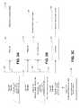
- FIGS. 5-10provide flowcharts of some exemplary processes that may be used to associate a tag with a participant in accordance with some embodiments of the present invention
- FIG. 11illustrates an exemplary system for automatically activating and/or deactivating tags in accordance with some embodiments of the present invention
- FIG. 12provides a flowchart of an exemplary process that may be used to automatically activate and/or register a tag in accordance with some embodiments of the present invention.
- FIG. 13illustrates a block diagram of components that may be included in devices for associating a tag with a participant in accordance with some embodiments of the present invention.
- RFIDRadio Frequency Identification
- the tagsmay first be registered with that particular participant, and then activated to begin tracking the participant.
- the term “associate” or “association” when described in relation to associating a tag with a participantmay encompass the process of registering and/or activating the tag with respect to the particular participant.
- Existing techniques for associating tags with particular entitiesmay be inadequate in environments with many active tags due to range precision limitations of devices used to program the tags.
- example embodimentsadvantageously provide for systems and methods that reduce the complexity of the process of associating a particular RF location tag or set of tags with a particular participant.
- tagsmay be selectively activated and deactivated.
- tagsmay be associated with power sources, such as batteries. When a tag is activated, the tag may begin to consume battery power.
- the use of battery power in this mannermay introduce certain tradeoffs. Longer tag life may require the use of larger batteries, increasing the size and weight of the tag.
- deactivating tags that are not in usebattery life may be conserved, allowing for the use of smaller batteries and extending the life of existing batteries.
- efficient activation and deactivationmay be difficult due to the need for the tag to be in close proximity with a device capable of performing the activation or deactivation. Enclosed environments, such as a locker room, may not be capable of supporting additional personnel to provide for tag activation and deactivation.
- participantshould be understood to include any physical item or person to which a particular RF location tag or set of tags may be associated.
- the term “participant” as used hereinmay refer to players, player equipment (e.g., a set of shoulder pads, a wristband, a jersey, or a helmet), officials, game related objects (e.g., a ball, penalty marker, line of scrimmage and yard to gain markers), and any other movable object proximate a monitored area such as a field of play.
- Embodiments of the present inventionare directed to methods, systems, apparatuses, and computer readable storage media for associating particular RF location tags with particular participants.
- Embodiments of the present inventionmay provide for automatic determination of participant identities and association of the entity identities with particular RF location tags as described in detail below.
- Embodiments of the present inventionmay provide for automated data collection with reduced errors, as well as providing additional statistics that may not be available with current systems.
- Embodiments of the present inventionmay allow for sensor derived data to be provided for use in the association of one or more RF location tags with a particular participant.
- sensor derived datamay be received from, without limitation, cameras, biometric readers (e.g., fingerprint readers, retinal scanners, facial recognition scanners, and the like), barcode readers, RFID receivers, near field communications (NFC) readers, global positioning system (GPS) receivers, or the like.
- biometric readerse.g., fingerprint readers, retinal scanners, facial recognition scanners, and the like
- barcode readerse.g., RFID receivers, near field communications (NFC) readers, global positioning system (GPS) receivers, or the like.
- NFCnear field communications
- GPSglobal positioning system
- FIG. 1illustrates an exemplary locating system 100 useful for calculating a location by an accumulation of position data or time of arrivals (TOAs) at a central processor/Hub 108 , whereby the TOAs represent a relative time of flight (TOF) from RTLS tags 102 as recorded at each receiver 106 (e.g., UWB reader, etc.).
- TOAsrepresent a relative time of flight (TOF) from RTLS tags 102 as recorded at each receiver 106 (e.g., UWB reader, etc.).
- a timing reference clockis used, in some examples, such that at least a subset of the receivers 106 may be synchronized in frequency, whereby the relative TOA data associated with each of the RTLS tags 102 may be registered by a counter associated with at least a subset of the receivers 106 .
- a reference tag 104preferably a UWB transmitter, positioned at known coordinates, is used to determine a phase offset between the counters associated with at least a subset of the of the receivers 106 .
- the RTLS tags 102 and the reference tags 104reside in an active RTLS field.
- the systems described hereinmay be referred to as either “multilateration” or “geolocation” systems, terms that refer to the process of locating a signal source by solving an error minimization function of a location estimate determined by the difference in time of arrival (DTOA) between TOA signals received at multiple receivers 106 .
- DTOAdifference in time of arrival
- the system comprising at least the tags 102 and the receivers 106is configured to provide two dimensional and/or three dimensional precision localization (e.g., subfoot resolutions), even in the presence of multipath interference, due in part to the use of short nanosecond duration pulses whose TOF can be accurately determined using detection circuitry, such as in the receivers 106 , which can trigger on the leading edge of a received waveform.
- this short pulse characteristicallows necessary data to be conveyed by the system at a higher peak power, but lower average power levels, than a wireless system configured for high data rate communications, yet still operate within local regulatory requirements.
- the tags 102may operate with an instantaneous ⁇ 3 dB bandwidth of approximately 400 MHz and an average transmission below 187 pulses in a 1 msec interval, provided that the packet rate is sufficiently low.
- the predicted maximum range of the systemoperating with a center frequency of 6.55 GHz, is roughly 200 meters in instances in which a 12 dBi directional antenna is used at the receiver, but the projected range will depend, in other examples, upon receiver antenna gain.
- the range of the systemallows for one or more tags 102 to be detected with one or more receivers positioned throughout a football stadium used in a professional football context.
- Such a configurationadvantageously satisfies constraints applied by regulatory bodies related to peak and average power densities (e.g., effective isotropic radiated power density (“EIRP”)), while still optimizing system performance related to range and interference.
- EIRPeffective isotropic radiated power density
- tag transmissions with a ⁇ 3 dB bandwidth of approximately 400 MHzyields, in some examples, an instantaneous pulse width of roughly 2 nanoseconds that enables a location resolution to better than 30 centimeters.
- the object to be locatedhas an attached tag 102 , preferably a tag having a UWB transmitter, that transmits a burst (e.g., multiple pulses at a 1 Mb/s burst rate, such as 112 bits of On-Off keying (OOK) at a rate of 1 Mb/s), and optionally, a burst comprising an information packet utilizing OOK that may include, but is not limited to, ID information, a sequential burst count or other desired information for object or personnel identification, inventory control, etc.
- a burste.g., multiple pulses at a 1 Mb/s burst rate, such as 112 bits of On-Off keying (OOK) at a rate of 1 Mb/s
- OOKOn-Off keying
- the tag 102may employ UWB waveforms (e.g., low data rate waveforms) to achieve extremely fine resolution because of their extremely short pulse (i.e., sub-nanosecond to nanosecond, such as a 2 nsec (1 nsec up and 1 nsec down)) durations.
- the information packetmay be of a short length (e.g. 112 bits of OOK at a rate of 1 Mb/sec, in some example embodiments), that advantageously enables a higher packet rate. If each information packet is unique, a higher packet rate results in a higher data rate; if each information packet is transmitted repeatedly, the higher packet rate results in a higher packet repetition rate.
- higher packet repetition ratee.g., 12 Hz
- higher data ratese.g., 1 Mb/sec, 2 Mb/sec or the like
- the shorter length of the information packetsin conjunction with other packet rate, data rates and other system requirements, may also result in a longer battery life (e.g., 7 years battery life at a transmission rate of 1 Hz with a 300 mAh cell, in some present embodiments).
- Tag signalsmay be received at a receiver directly from RTLS tags, or may be received after being reflected en route. Reflected signals travel a longer path from the RTLS tag to the receiver than would a direct signal, and are thus received later than the corresponding direct signal. This delay is known as an echo delay or multipath delay. If reflected signals are sufficiently strong enough to be detected by the receiver, they can corrupt a data transmission through inter-symbol interference.
- the tag 102may employ UWB waveforms to achieve extremely fine resolution because of their extremely short pulse (e.g., 2 nsec) durations.
- signalsmay comprise short information packets (e.g., 112 bits of OOK) at a somewhat high burst data rate (1 Mb/sec, in some example embodiments), that advantageously enable packet durations to be brief (e.g. 112 microsec) while allowing inter-pulse times (e.g., 998 nsec) sufficiently longer than expected echo delays, avoiding data corruption.
- short information packetse.g., 112 bits of OOK
- Reflected signalscan be expected to become weaker as delay increases due to more reflections and the longer distances traveled.
- inter-pulse timee.g. 998 nsec
- path length differencee.g. 299.4 m.
- minimization of packet durationallows the battery life of a tag to be maximized, since its digital circuitry need only be active for a brief time. It will be understood that different environments can have different expected echo delays, so that different burst data rates and, hence, packet durations, may be appropriate in different situations depending on the environment.
- Minimization of the packet durationalso allows a tag to transmit more packets in a given time period, although in practice, regulatory average EIRP limits may often provide an overriding constraint.
- brief packet durationalso reduces the likelihood of packets from multiple tags overlapping in time, causing a data collision.
- minimal packet durationallows multiple tags to transmit a higher aggregate number of packets per second, allowing for the largest number of tags to be tracked, or a given number of tags to be tracked at the highest rate.
- a data packet length of 112 bits(e.g., OOK encoded), transmitted at a data rate of 1 Mb/sec (1 MHz), may be implemented with a transmit tag repetition rate of 1 transmission per second (1 TX/sec).
- Such an implementationmay accommodate a battery life of up to seven years, wherein the battery itself may be, for example, a compact, 3-volt coin cell of the series no. BR2335 (Rayovac), with a battery charge rating of 300 mAhr.
- An alternate implementationmay be a generic compact, 3-volt coin cell, series no. CR2032, with a battery charge rating of 220 mAhr, whereby the latter generic coin cell, as can be appreciated, may provide for a shorter battery life.
- the high burst data transmission rate(e.g., 1 MHz), coupled with the short data packet length (e.g., 112 bits) and the relatively low repetition rates (e.g., 1 TX/sec), provide for two distinct advantages in some examples: (1) a greater number of tags may transmit independently from the field of tags with a lower collision probability, and/or (2) each independent tag transmit power may be increased, with proper consideration given to a battery life constraint, such that a total energy for a single data packet is less than a regulated average power for a given time interval (e.g., a 1 msec time interval for an FCC regulated transmission).
- a regulated average power for a given time intervale.g., a 1 msec time interval for an FCC regulated transmission.
- additional sensor or telemetry datamay be transmitted from the tag to provide the receivers 106 with information about the environment and/or operating conditions of the tag.
- the tagmay transmit a temperature to the receivers 106 .
- Such informationmay be valuable, for example, in a system involving perishable goods or other refrigerant requirements.
- the temperaturemay be transmitted by the tag at a lower repetition rate than that of the rest of the data packet.
- the temperaturemay be transmitted from the tag to the receivers at a rate of one time per minute (e.g., 1 TX/min.), or in some examples, once every 720 times the data packet is transmitted, whereby the data packet in this example is transmitted at an example rate of 12 TX/sec.
- the tag 102may be programmed to intermittently transmit data to the receivers 106 in response to a signal from a magnetic command transmitter (not shown).
- the magnetic command transmittermay be a portable device, functioning to transmit a 125 kHz signal, in some example embodiments, with a range of approximately 15 feet or less, to one or more of the tags 102 .
- the tags 102may be equipped with at least a receiver tuned to the magnetic command transmitter transmit frequency (e.g., 125 kHz) and functional antenna to facilitate reception and decoding of the signal transmitted by the magnetic command transmitter.
- one or more other tagsmay be positioned within and/or about a monitored region.
- the reference tag 104may be configured to transmit a signal that is used to measure the relative phase (e.g., the count of free-running counters) of non-resettable counters within the receivers 106 .
- One or more (e.g., preferably four or more) receivers 106are also positioned at predetermined coordinates within and/or around the monitored region.
- the receivers 106may be connected in a “daisy chain” fashion to advantageously allow for a large number of receivers 106 to be interconnected over a significant monitored region in order to reduce and simplify cabling, provide power, and/or the like.
- Each of the receivers 106includes a receiver for receiving transmissions, such as UWB transmissions, and preferably, a packet decoding circuit that extracts a time of arrival (TOA) timing pulse train, transmitter ID, packet number, and/or other information that may have been encoded in the tag transmission signal (e.g., material description, personnel information, etc.) and is configured to sense signals transmitted by the tags 102 and one or more reference tags 104 .
- TOAtime of arrival
- Each receiver 106includes a time measuring circuit that measures times of arrival (TOA) of tag bursts, with respect to its internal counter.
- the time measuring circuitis phase-locked (e.g., phase differences do not change and therefore respective frequencies are identical) with a common digital reference clock signal distributed via cable connection from a Central Processor/Hub 108 having a central timing reference clock generator.
- the reference clock signalestablishes a common timing reference for the receivers 106 .
- multiple time measuring circuits of the respective receivers 106are synchronized in frequency, but not necessarily in phase. While there typically may be a phase offset between any given pair of receivers in the receivers 106 , the phase offset is readily determined through use of a reference tag 104 .
- each receivermay be synchronized wirelessly via virtual synchronization without a dedicated physical timing channel.
- the receivers 106are configured to determine various attributes of the received signal. Since measurements are determined at each receiver 106 , in a digital format, rather than analog in some examples, signals are transmittable to the Central Processor/Hub 108 .
- the receivers 106can receive and process tag (and corresponding object) locating signals on a nearly continuous basis. As such, in some examples, the receiver memory allows for a high burst rate of tag events (i.e., information packets) to be captured.
- Data cables or wireless transmissionsmay convey measurement data from the receivers 106 to the Central Processor/Hub 108 (e.g., the data cables may enable a transfer speed of 2 Mbps). In some examples, measurement data is transferred to the Central Processor/Hub at regular polling intervals.
- the Central Processor/Hub 108determines or otherwise computes tag location (i.e., object position) by processing TOA measurements relative to multiple data packets detected by the receivers 106 .
- the Central Processor/Hub 108may be configured to resolve the coordinates of a tag using nonlinear optimization techniques.
- TOA measurements from multiple receivers 106are processed by the Central Processor/Hub 108 to determine a position of the transmit tag 102 by a differential time-of-arrival (DTOA) analysis of the multiple TOAs.
- the DTOA analysisincludes a determination of tag transmit time t 0 , whereby a time-of-flight (TOF), measured as the time elapsed from the estimated tag transmit time t 0 to the respective TOA, represents graphically the radii of spheres centered at respective receivers 106 .
- TOFtime-of-flight
- the distance between the surfaces of the respective spheres to the estimated position coordinates (x 0 , y 0 , z 0 ) of the transmit tag 102represents the measurement error for each respective TOA, and the minimization of the sum of the squares of the TOA measurement errors from each receiver participating in the DTOA position estimate provides for both the position coordinates (x 0 , y 0 , z 0 ) of the transmit tag and of that tag's transmit time t 0 .
- the system described hereinmay be referred to as an “over-specified” or “over-determined” system.
- the Central Processor/Hub 108may calculate one or more valid (i.e., most correct) positions based on a set of measurements and/or one or more incorrect (i.e., less correct) positions. For example, a position may be calculated that is impossible due the laws of physics or may be an outlier when compared to other calculated positions. As such one or more algorithms or heuristics may be applied to minimize such error.
- Nis the number of receivers
- cis the speed of light
- (x j , y j , z j )are the coordinates of the j th receiver
- t jis the arrival time at the j th receiver
- t 0is the tag transmit time.
- the variable t 0represents the time of transmission. Since t 0 is not initially known, the arrival times, t j , as well as t 0 , are related to a common time base, which in some examples, is derived from the arrival times. As a result, differences between the various arrival times have significance for determining location as well as t 0 .
- the optimization algorithm to minimize the error ⁇ in Equation 1may be the Davidon-Fletcher-Powell (DFP) quasi-Newton algorithm, for example.
- the optimization algorithm to minimize the error ⁇ in Equation 1may be a steepest descent algorithm.
- the algorithmsmay be seeded with an initial position estimate (x, y, z) that represents the two-dimensional (2D) or three-dimensional (3D) mean of the positions of the receivers 106 that participate in the tag position determination.
- the RTLS systemcomprises a receiver grid, whereby each of the receivers 106 in the receiver grid keeps a receiver clock that is synchronized, with an initially unknown phase offset, to the other receiver clocks.
- the phase offset between any receiversmay be determined by use of a reference tag that is positioned at a known coordinate position (x T , y T , z T ).
- the phase offsetserves to resolve the constant offset between counters within the various receivers 106 , as described below.
- Each receiver R jutilizes, for example, a synchronous clock signal derived from a common frequency time base, such as a clock generator. Because the receivers are not synchronously reset, an unknown, but constant offset O j exists for each receiver's internal free running counter. The value of the constant offset O j is measured in terms of the number of fine resolution count increments (e.g., a number of nanoseconds for a one nanosecond resolution system).
- the reference tagis used, in some examples, to calibrate the radio frequency locating system as follows:
- the reference tagemits a signal burst at an unknown time ⁇ R .
- phase offsets expressed as differential count valuesare determined as given in Equations 5a-b:
- Equation 6a-bEquation 6a-b
- Each arrival time, t jcan be referenced to a particular receiver (receiver “1”) as given in Equation 7:
- Equation 1The minimization, described in Equation 1, may then be performed over variables (x, y, z, t 0 ) to reach a solution (x′, y′, z′, t 0 ′).
- the location of a tag 102may then be output to the receiver processing and distribution system 110 for further processing of the location data to advantageously provide visualizations, predictive analytics and/or the like.
- each objectmay have one or more attached tags 102 (such as to equipment worn by a player) to be used to track data such as location, change of location, speed, or the like of each object.
- tags 102such as to equipment worn by a player
- additional sensorssuch as accelerometers, health sensors, temperature sensors, moisture sensors, light sensors, or the like, may be attached to each object to provide further data to the performance analytics system.
- Such additional sensorsmay provide data to the tag 102 , either through a wired or wireless connection, to be transmitted to the receivers 106 or the sensors may be configured to transmit data to dedicated receivers separately from tags 102 .
- One or more of the receivers 106may receive transmissions from tags 102 and transmit the tag data to a receiver hub 108 .
- the receiver hub 108may process the received data to determine a tag location for the tags 102 .
- the receiver hub 108may transmit the tag location data to one or more processors, such as receiver processing and distribution system 110 .
- Receiver processing and distribution system 110may use one or more modules (e.g., processing engines) and one or more databases to identify the object each of the tags 102 is associated with, such as a player, official, ball, or the like.
- multiple tags 102may be attached to the equipment worn by a participant (e.g., an individual player or official).
- the receiver processing and distribution system 110may use a database to associate the tag identifier of each tag 102 with each player, official, object, or other participant and correlate the tag location data and/or other sensor data for multiple tags 102 that are associated with a particular player, official, object, or other participant.
- the receiver processing and distribution system 110may then use the tag location data to determine player dynamics, such as a player's location, how the location is changing with time, velocity, acceleration, deceleration, total yardage, or the like.
- the receiver processing and distribution system 110may also use the tag location data and sensor derived data to determine the identity of a participant for association of the tag with the particular participant.
- the receiver processing and distribution system 110may also use the data and one or more databases to determine team formations, play activity, events, statistics, or the like, such as by comparing the data to various models to determine the most likely formation or play or the events that have occurred during a game.
- the receiver processing and distribution system 110may also use the data to provide statistics or other output data for the players, teams, and the game.
- FIG. 1shows a monitored area 100 .
- the monitored area 100comprises a plurality of positions at one or more time epochs.
- the plurality of positionsmay be divided into one or more regions, called zones.
- Each zonemay be described by one or more coordinate systems, such as a local NED (North-East-Down) system, a latitude-longitude system, or even a yard line system as might be used for an American football game.
- a locationis a description of a position, or a plurality of positions, within the monitored area. For example, a field marker at the intersection of the south goal line and west out of bounds line at Bank of America Stadium in Charlotte, N.C.
- a Geographical Information System or similar monitored area databasemay be used to associate location data.
- One type of Geographical Information System describing at least a field of playmay be called Field Data.
- FIGS. 2A-Cillustrate some exemplary participants that may provide information to a performance analytics system in accordance with some embodiments of the present invention.
- FIG. 2Aillustrates a player 202 (e.g., a football player) wearing equipment having attached tags 102 in accordance with some embodiments.
- the depicted player 202is wearing shoulder pads having tags 102 affixed to opposite sides thereof. This positioning advantageously provides an elevated broadcast position for each tag 102 thereby increasing its communication effectiveness.
- Additional sensors 203may be attached to equipment worn by player 202 , such as accelerometers, magnetometers, time-of-flight sensors, health monitoring sensors (e.g., blood pressure sensors, heart monitors, respiration sensors, moisture sensors, temperature sensors), light sensors, or the like.
- the additional sensors 203may be affixed to shoulder pads, the helmet, the shoes, rib pads, elbow pads, the jersey, the pants, a bodysuit undergarment, gloves, arm bands, wristbands, and the like.
- Sensors 203may be configured to communicate with receivers (e.g., receivers 106 of FIG. 1 ) directly or indirectly through tags 102 or other transmitters.
- a sensor 203may be connected, wired (e.g., perhaps through wires sewn into a jersey or bodysuit undergarment) or wirelessly, to tags 102 to provide sensor derived data to tags 102 , which is then transmitted to the receivers 106 .
- a plurality of sensorsmay be connected to a dedicated antenna or transmitter, perhaps positioned in the helmet, which may transmit sensor derived data to one or more receivers.
- FIG. 2Billustrates a game official 206 wearing equipment having attached tags 102 and sensors 203 in accordance with some embodiments.
- tags 102are attached to the official's jersey proximate opposite shoulders.
- Sensors 203are positioned in wristbands worn on the official's wrists as shown.
- Sensors 203may be configured to communicate with receivers (e.g., receivers 106 of FIG. 1 ) directly or indirectly through tags 102 or other transmitters as discussed above in connection with FIG. 2A .
- the positioning of sensors 203may allow the receiver processing and distribution system 110 to determine particular motions, movements, or activities of the official 206 for use in determining events (e.g., winding of the game clock, first down, touchdown, or the like).
- the official 206may also carry other equipment, such as penalty flag 208 , which may also have a tag 102 (and optionally one or more sensors) attached to provide additional data to the receiver processing and distribution system 110 .
- the receiver processing and distribution system 110may use tag location data from the penalty flag 208 to determine when the official is merely carrying the penalty flag 208 versus when the official is using the penalty flag 208 to indicate an event, such as a penalty (e.g., by throwing the penalty flag 208 ).
- FIG. 2Cillustrates an example of a ball 210 having tags 102 attached or embedded in accordance with some embodiments.
- sensors 203may be attached to or embedded in the ball 210 , such as accelerometers, time-of-flight sensors, or the like.
- the sensor 203may be connected, wired or wirelessly, to tag 102 to provide sensor data to tag 102 which is then transmitted to the receivers 106 .
- the sensor 203may transmit sensor data to receivers separately from the tag 102 , such as described above in connection with FIG. 2A .
- tags 102 and sensors 203 of FIGS. 2A-Cmay be correlated to such participants.
- unique tag or sensor identifiers(“unique IDs”) may be correlated to a participant profile (e.g., John Smith—running back, Fred Johnson—line judge official, or ID 027—one of several game balls, etc.) and stored to a remote database accessible to the performance analytics system as discussed in greater detail below.
- Each participant profilemay further include or be correlated with a variety of data including, but not limited to, biometric data (e.g., height, weight, health data, etc.), role data, team ID, performance statistics, and other data that may be apparent to one of skill in the art in view of the foregoing description.
- biometric datae.g., height, weight, health data, etc.
- role datae.g., role data
- team IDe.g., role data
- performance statisticse.g., performance statistics, and other data that may be apparent to one of skill in the art in view of the foregoing description.
- participant profile or role datamay be pre-defined and stored in association with the unique tag or sensor identifiers.
- the participant profile or role datamay also be “learned” by the system as a result of received tag or sensor data, formation data, play data, event data, and/or the like.
- the systemmay determine that a tag or sensor is not correlated to a participant profile and may analyze data received from the tag and/or sensor to determine possible participant roles, etc., which may be ranked and then selected/confirmed by the system or by a user after being displayed by the system.
- the systemmay determine possible participant roles (i.e., participant role data) based on determined participant location data (e.g., movement patterns, alignment position, etc.).
- the participant profile or role datamay also be updated by the system (i.e., to produce a data set for the participant that is far more robust than that established at initial registration) as a result of received tag or sensor data, formation data, play data, event data, and/or the like.
- the participant profile and/or role datamay be used in a performance analytics system to weight the actions of the participants during analysis to assist in qualifying what is occurring, such as in determining formations, plays, events, etc.
- FIGS. 3A, 3B, 3C, 3D, and 3Eshow block diagrams of various different architectures that may be utilized in transmitting signals from one or more tags and sensors to one or more receivers of a receiver processing and analytics system in accordance with embodiments of the invention.
- the depicted architecturesmay be used in connection with the receiver processing and analytics system 110 of FIG. 1 . More than one of these architectures may be used together in a single system.
- FIG. 3Ashows a RF location tag 102 , such as that shown in FIG. 1 , which may be configured to transmit a tag signal to one or more receivers 106 .
- the one or more receivers 106may transmit a receiver signal to the receiver hub/locate engine 108 .
- the depicted RF location tag 102may generate or store a tag unique identifier (“tag UID”) and/or tag data as shown.
- the tag datamay include useful information such as the installed firmware version, last tag maintenance date, configuration information, and/or a tag-participant correlator.
- the tag-participant correlatormay comprise data that indicates that a monitored participant is associated with the RF location tag 102 (e.g., name, uniform number and team, biometric data, tag position on the participant, i.e., right wrist).
- the tag-participant correlatormay be stored to the RF location tag 102 when the tag is registered or otherwise associated with a participant. While shown as a separate field for illustration purposes, one of ordinary skill in the art may readily appreciate that the tag-participant correlator may be part of any tag data or even omitted from the tag.
- the tag signal transmitted from RF location tag 102 to receiver 106may include “blink data” as it is transmitted at selected intervals. This “blink rate” may be set by the tag designer or the system designer to meet application requirements. In some embodiments it is consistent for one or all tags; in some embodiments it may be data dependent. Blink data includes characteristics of the tag signal that allow the tag signal to be recognized by the receiver 106 so the location of the RF location tag 102 may be determined by the locating system. Blink data may also comprise one or more tag data packets. Such tag data packets may include any data from the tag 102 that is intended for transmission such as, for example in the depicted embodiment, a tag UID, tag data, and a tag-participant correlator.
- the blink datamay be or include a specific pattern, code, or trigger that the receiver 106 (or downstream receiver processing and analytics system) detects to identify that the transmission is from a RF location tag 102 (e.g., a UWB tag).
- a RF location tag 102e.g., a UWB tag
- the depicted receiver 106receives the tag signal, which includes blink data and tag data packets as discussed above.
- the receiver 106may pass the received tag signal directly to the receive hub/locate engine 108 as part of its receiver signal.
- the receiver 106could perform some basic processing on the received tag signal. For instance, the receiver could extract blink data from the tag signal and transmit the blink data to the receive hub/locate engine 108 .
- the receivercould transmit a time measurement to the receive hub/locate engine 108 such as a TOA measurement and/or a TDOA measurement.
- the time measurementcould be based on a clock time generated or calculated in the receiver, it could be based on a receiver offset value as explained above, it could be based on a system time, and/or it could be based on the time difference of arrival between the tag signal of the RF location tag 102 and the tag signal of a RF reference tag (e.g., tag 104 of FIG. 1 ).
- the receiver 106could additionally or alternatively determine a signal measurement from the tag signal (such as a received signal strength indication (RSSI), a direction of signal, signal polarity, or signal phase) and transmit the signal measurement to the receive hub/locate engine 108 .
- RSSIreceived signal strength indication
- FIG. 3Bshows a RF location tag 202 and sensor 203 , such as those associated with a participant as shown in FIG. 2 , which may be configured to transmit tag signals and sensor signals, respectively, to one or more receivers 106 , 166 .
- the one or more receivers 106 , 166may then transmit receiver signals to the receiver hub/locate engine 108 .
- One or more receivers 106 , 166may share physical components, such as a housing or antenna.
- the depicted RF location tag 202may comprise a tag UID and tag data (such as a tag-participant correlator) and transmit a tag signal comprising blink data as discussed in connection with FIG. 3A above.
- the depicted sensor 203may generate and/or store a sensor UID, additional stored sensor data (e.g. a sensor-participant correlator, sensor type, sensor firmware version, last maintenance date, the units in which environmental measurements are transmitted, etc.), and environmental measurements.
- the “additional stored sensor data” of the sensor 203may include any data that is intended for transmission, including but not limited to a RF location tag 202 , a reference tag (e.g., 104 of FIG. 1 ), a sensor receiver, a receiver 106 , and/or the receiver/hub locate engine 108 .
- the sensor-participant correlatormay comprise data that indicates that a monitored participant is associated with the sensor 203 (e.g., name, uniform number and team, biometric data, sensor position on participant, i.e., right wrist).
- the sensor-participant correlatormay be stored to the sensor 203 when the sensor is registered or otherwise associated with a participant. While shown as a separate field for illustration purposes, one of ordinary skill in the art may readily appreciate that the sensor-participant correlator may be part of any additional stored sensor data or omitted from the sensor altogether.
- Sensors such as sensor 203 that are structured according to embodiments of the inventionmay sense or determine one or more environmental conditions (e.g. temperature, pressure, pulse, heartbeat, rotation, velocity, acceleration, radiation, position, chemical concentration, voltage) and store or transmit “environmental measurements” that are indicative of such conditions.
- environmental measurementsincludes measurements concerning the environment proximate the sensor including, without limitation, ambient information (e.g., temperature, position, humidity, etc.) and information concerning a participant's health, fitness, operation, and/or performance.
- Environmental measurementsmay be stored or transmitted in either analog or digital form and may be transmitted as participant measurements, as a set of participant measurements, and/or as summary statistics.
- temperature in degrees Celsiusmay be transmitted as ⁇ 31 ⁇ , or as ⁇ 33, 32, 27, 22, 20, 23, 27, 30, 34, 31 ⁇ , or as ⁇ 27.9 ⁇ .
- the sensor-participant correlatorcould be determined at least in part from the environmental measurements.
- RF location tag 202transmits a tag signal to receiver 106 and sensor 203 transmits a sensor signal to sensor receiver 166 .
- the sensor signalmay comprise one or more sensor information packets.
- sensor information packetsmay include any data or information from the sensor 203 that is intended for transmission such as, for example in the depicted embodiment, sensor UID, additional stored sensor data, sensor-participant correlator, and environmental measurements.
- a receiver signal from receiver 106 and a sensor receiver signal from sensor receiver 166may be transmitted via wired or wireless communication to receiver hub/locate engine 108 as shown.
- FIG. 3Cdepicts a sensor 203 communicating through a RF location tag 202 in accordance with various embodiments.
- the sensor 203may be part of (i.e., reside in the same housing or assembly structure) of the RF location tag 202 .
- the sensor 203may be distinct from (i.e., not resident in the same housing or assembly structure) the RF location tag 202 but configured to communicate wirelessly or via wired communication with the RF location tag 202 .
- the RF location tag 202 , the sensor 203 , or bothmay generate and/or store a tag-sensor correlator that indicates an association between a RF location tag 202 and a sensor 203 (e.g., tag UID/sensor UID, distance from tag to sensor in a particular stance, set of sensors associated with a set of tags, sensor types associated with a tag, etc.).
- a tag-sensor correlatorthat indicates an association between a RF location tag 202 and a sensor 203 (e.g., tag UID/sensor UID, distance from tag to sensor in a particular stance, set of sensors associated with a set of tags, sensor types associated with a tag, etc.).
- both the RF location tag 202 and the sensor 203store the tag-sensor correlator.
- sensor 203transmits a sensor signal to RF location tag 202 .
- the sensor signalmay comprise one or more sensor information packets as discussed above.
- the sensor information packetsmay comprise the sensor UID, a sensor-participant correlator, additional stored sensor data, the tag-sensor correlator, and/or the environmental measurements.
- the RF location tag 202may store some portion of, or all of, the sensor information packets locally and may package the sensor information packets into one or more tag data packets for transmission to receiver 106 as part of a tag signal or simply pass them along as part of its tag signal.
- FIG. 3Dillustrates an example communication structure for a reference tag 104 (e.g., reference tag 104 of FIG. 1 ), an RF location tag 202 , a sensor 203 , and two receivers 106 in accordance with one embodiment.
- the depicted reference tag 104is a RF location tag and thus may include tag data, a tag UID, and is capable of transmitting tag data packets.
- the reference tag 104may form part of a sensor and may thus be capable of transmitting sensor information packets.
- the depicted sensor 203transmits a sensor signal to RF reference tag 104 .
- the RF reference tag 104may store some portion or some or all of the sensor information packets locally and may package the sensor information packets into one or more tag data packets for transmission to receiver 106 as part of a tag signal, or simply pass them along as part of its tag signal.
- the receivers 106 of FIG. 3Dare configured to receive tag signals from the RF location tag 202 and the reference tag 104 .
- Each of these tag signalsmay include blink data, which may comprise tag UIDs, tag data packets, and/or sensor information packets.
- the receivers 106each transmit receiver signals via wired or wireless communication to the receiver hub/locate engine 108 as shown.
- FIG. 3Eillustrates an example communication structure between an RF location tag 202 , a plurality of receivers 106 , and a variety of sensor types including, without limitation, a sensor 203 , a diagnostic device 233 , a triangulation positioner 243 , a proximity positioner 253 , and a proximity label 263 in accordance with various embodiments.
- a sensor 203a diagnostic device 233 , a triangulation positioner 243 , a proximity positioner 253 , and a proximity label 263 in accordance with various embodiments.
- none of the sensors 203 , 233 , 243 , 253form part of an RF location tag 202 or reference tag 104 .
- eachmay comprise a sensor UID and additional stored sensor data.
- Each of the depicted sensors 203 , 233 , 243 , 253transmits sensor signals comprising sensor information packets.
- receiver 106is configured to receive a tag signal from RF location tag 202 and a sensor signal directly from sensor 203 .
- sensor 203may be configured to communicate in a communication protocol that is common to RF location tag 202 as will be apparent to one of ordinary skill in the art in view of this disclosure.
- FIG. 3Edepicts one type of sensor referred to herein as a “proximity interrogator”.
- the proximity interrogator 223can include circuitry operative to generate a magnetic, electromagnetic, or other field that is detectable by a RF location tag 202 . While not shown in FIG. 3E , a proximity interrogator 223 may include a sensor UID and other tag and sensor derived data or information as discussed above.
- the proximity interrogator 223is operative as a proximity communication device that can trigger a RF location tag 202 (e.g., when the RF location tag 202 detects the field produced by the proximity interrogator 223 ) to transmit blink data under an alternate blink pattern or blink rate.
- the RF location tagcan initiate a preprogrammed (and typically faster) blink rate to allow more location points for tracking a participant.
- the RF location tagmay not transmit a tag signal until triggered by the proximity interrogator 223 .
- the RF location tag 202may be triggered when the RF location tag 202 moves near (e.g., within communication proximity to) a proximity interrogator 223 .
- the RF location tagmay be triggered when the proximity interrogator 223 moves near to the RF location tag 202 .
- the RF location tag 202may be triggered when a button is pressed or a switch is activated on the proximity interrogator 223 or on the RF location tag itself.
- a proximity interrogator 223could be placed at the start line of a racetrack. Every time a car passes the start line, a car-mounted RF location tag 202 senses the signal from the proximity interrogator and is triggered to transmit a tag signal indicating that a lap has been completed.
- a proximity interrogator 223could be placed at a Gatorade cooler.
- a participant-mounted RF location tag 202senses the signal from the proximity interrogator and is triggered to transmit a tag signal indicating that Gatorade has been consumed.
- a proximity interrogator 223could be placed on a medical cart. When paramedics use the medical cart to pick up a participant (e.g., a player) and move him/her to the locker room, a participant-mounted RF location tag 202 senses the signal from the proximity interrogator and is triggered to transmit a tag signal indicating that they have been removed from the game.
- any of these post-triggered tag signalsmay differ from pre-triggered tag signals in terms of any aspect of the analog and/or digital attributes of the transmitted tag signal.
- FIG. 3Edepicts another type of sensor that is generally not worn by a participant but is referred to herein as a “diagnostic device”. However, like other sensors, diagnostic devices may measure one or more environmental conditions and store corresponding environmental measurements in analog or digital form.
- the depicted diagnostic device 233may generate and store a sensor-participant correlator for association with environmental measurements taken in connection with a specific participant.
- the diagnostic device 233may be a blood pressure meter that is configured to store as environmental measurements blood pressure data for various participants. Each set of environmental measurements (e.g., blood pressure data) may be stored and associated with a sensor-participant correlator.
- the depicted diagnostic device 233is configured to transmit a sensor signal comprising sensor information packets to a sensor receiver 166 .
- the sensor information packetsmay comprise one or more of the sensor UID, the additional stored data, the environmental measurements, and/or the sensor-participant correlator as discussed above.
- the sensor receiver 166may associate some or all of the data from the sensor information packets with other stored data in the sensor receiver 166 or with data stored or received from other sensors, diagnostic devices, RF location tags 102 , or reference tags.
- the sensor receiver 166transmits a sensor receiver signal to a receiver hub/locate engine 108 .
- triangulation positioner 243Another type of sensor shown in FIG. 3E is a triangulation positioner 243 .
- a “triangulation positioner”is a type of sensor that senses position.
- the depicted triangulation positioner 243includes a sensor UID, additional stored sensor data, and environmental measurements as discussed above.
- a triangulation positioneralso known as a global positioning system (GPS) receiver receives clock data transmitted by one or more geostationary satellites (a satellite in a known or knowable position) and/or one or more ground based transmitters (also in known or knowable positions), compares the received clock data, and computes a “position calculation”.
- the position calculationmay be included in one or more sensor information packets as environmental measurements.
- a triangulation positionercomprises one or more cameras or image-analyzers that receive emitted or reflected light or heat, and then analyzes the received images to determine the location of a participant or sensor.
- a triangulation positionermay transmit data wirelessly, it is not a RF location tag because it does not transmit blink data or a tag signal that can be used by a receiver hub/locate engine 108 to calculate location.
- a triangulation positionersenses position and computes a position calculation that may then be used as environmental measurements by the receiver hub/locate engine 108 .
- a triangulation positionercould be combined with a RF location tag or reference tag (not shown).
- the triangulation positionercould compute and transmit its position calculation via the RF location tag to one or more receivers.
- the receiver hub/locate enginewould calculate tag location based on the blink data received as part of the tag signal and not based solely on the position calculation.
- the position calculationwould be considered as environmental measurements and may be included in associated sensor information packets.
- position calculationsare not as accurate as the location calculations (e.g., UWB waveform based location calculations) performed by receiver hub/locate engines structured in accordance with various embodiments of the invention. That is not to say that position calculations may not be improved using known techniques. For example, a number of influences, including atmospheric conditions, can cause GPS accuracy to vary over time.
- DGPSdifferential global positioning system
- triangulation positionersreceive clock data from geostationary satellites, determine a position calculation, and broadcast a difference between the position calculation and the stored coordinates.
- This DGPS correction signalcan be used to correct for these influences and significantly reduce location estimate error.
- a “proximity detector”is a type of sensor that senses identity within an area (e.g., a local area) that is small with respect to the monitored area 100 of FIG. 1 .
- identitye.g., a unique ID or other identifier for a sensed object or participant
- NFCnear field communication
- RFID tagsuch as a UHF tag, HF tag, or low frequency tag
- an optical character recognition devicee.g., a biometric scanner, or a facial recognition system.
- a proximity detectorsenses an attribute of a participant (or a participant's wristband, tag, label, card, badge, clothing, uniform, costume, phone, ticket, etc.).
- the identity sensed by a proximity detectormay be stored locally at the proximity detector 253 as shown and transmitted as environmental measurements via one or more sensor information packets to a sensor receiver 166 .
- a proximity detector 253may have a defined position, which is often stationary, and may be associated with a location in the monitored area 100 of FIG. 1 .
- a proximity detector 253could be located at a finish line of a race track, an entrance gate of a stadium, with a diagnostic device, at a goal line or goal post of a football field, at a base or home plate of a baseball diamond, or a similar fixed location.
- the position coordinates of the proximity detector and a sensor UIDcould be stored to a monitored area database (not shown) that is accessible by one or more of the receivers 106 , 166 , the receiver hub/locate engine 108 , and/or other components of the receiver processing and analytics system 110 .
- a position calculationcould be determined with a triangulation positioner, or the proximity detector could be combined with a RF location tag and located by the receiver hub/locate engine 108 . While shown as separate fields for illustration purposes in FIG. 3E , identify information and position calculation could comprise part of the additional stored sensor data, the environmental measurements, or both.
- the proximity detectorcould be associated with a reference tag (e.g., tag 104 of FIG. 1 ) whose position is recorded in the monitored area database.
- the proximity detectoris movable, such that it may be transported to where it is needed.
- a proximity detector 253could be located on a medical cart, first down marker, a diagnostic device, goal post, or carried by a paramedic or security guard.
- the proximity detector 253is movable it would typically be associated with a RF location tag or triangulation positioner so that location (for a RF location tag) or position (for a triangulation positioner) can be determined at the time identity is sensed.
- the receiver hub/locate engine 108would locate the associated RF location tag, and the tag data/sensor data filter 112 would associate the tag location data for the associated RF location tag as the position of the proximity detector, while determining the identity of an associated participant from any received sensor information packets.
- the triangulation positionerwould compute a position calculation that could be stored as additional stored sensor data and/or environmental measurements, and transmitted as one or more sensor information packets.
- sensor information packets for a proximity detectormay include both sensed identity information and a position calculation.
- a proximity label 263has a fixed position and an identification code (e.g., a sensor UID).
- the proximity label 263may further comprise additional stored sensor data as shown.
- the depicted proximity label 263is configured to be read by proximity detector 253 .
- proximity detector 253may be further configured to write information to proximity label 263 .
- a proximity label 263may be a sticker, card, tag, passive RFID tag, active RFID tag, NFC tag, ticket, metal plate, electronic display, electronic paper, inked surface, sundial, or otherwise visible or machine readable identification device as is known in the art.
- the coordinates of the position of the proximity label 263are stored such that they are accessible to the receive hub/locate engine 108 .
- the position coordinates of a proximity label 263could be stored in a field database or monitored area database accessible via a network, or stored locally as additional stored data in the proximity detector 253 .
- a position of the proximity label 263is encoded into the proximity label 263 itself.
- coordinates of a position of the proximity label 263could be encoded into a passive RFID tag that is placed in that position.
- the coordinates of a position of the proximity label 263could be encoded into a printed barcode that is placed in that position.
- a proximity label 263 comprising a NFC tagcould be encoded with the location “end zone”, and the NFC tag could be placed at or near an end zone at Bank of America stadium.
- the stored coordinates of the proximity label 263may be offset from the actual coordinates of the proximity label 263 by a known or determinable amount.
- a proximity label 263such as an NFC tag may be encoded with a position.
- a sensorsuch as a proximity detector approaches the NFC tag it may read the position, then transmit the position in a sensor information packet to the sensor receiver 166 ′ and eventually to the receiver hub/locate engine 108 .
- a proximity label 263such as a barcode label may be encoded with an identification code.
- a smartphone with a proximity detectorsuch as a barcode imager
- a triangulation positionersuch as a GPS chip, GPS application, or similar device
- smartphonemay read the identification code from the barcode, determine a position calculation from received clock data, then transmit the identity and the position calculation to sensor receiver 166 ′ and eventually to the receiver hub/locate engine 106 as part of one or more sensor information packets.
- triangulation positioner 243 and proximity detector 253are each configured to transmit sensor signals carrying sensor information packets to sensor receiver 166 ′.
- the depicted sensors 243 , 253may transmit sensor signals via wired or wireless communication protocols.
- any proprietary or standard wireless protocole.g., 802.11, Zigbee, ISO/IEC 802.15.4, ISO/IEC 18000, IrDA, Bluetooth, CDMA, or any other protocol
- any standard or proprietary wired communication protocole.g., Ethernet, Parallel, Serial, RS-232, RS-422, USB, Firewire, I2C, etc.
- sensor receiver 166 ′, and any receiver discussed hereinmay use similar wired and wireless protocols to transmit receiver signals to the receiver hub/locate engine.
- the sensor receiver 166 ′may associate some or all of the data from the received sensor information packets with other data stored to the sensor receiver 166 ′, or with data stored or received from other sensors (e.g., sensor 203 ), diagnostic devices 233 , RF location tags 102 , or RF reference tags 104 . Such associated data is referred to herein as “associated sensor data”.
- the sensor receiver 166 ′is configured to transmit some or all of the received sensor information packets and any associated sensor data to the receiver hub/locate engine 108 at part of a sensor receiver signal.
- a smartphonecomprising a proximity detector (such as a barcode imager) and a triangulation positioner (such as a GPS chip) may associate an identification code determined from a barcode with a position calculation from received clock data as associated sensor data and transmit a sensor information packet that includes such associated sensor data to the receiver hub/locate engine 108 .
- the smartphonecould transmit a first sensor information packet including the identification code and the smartphone's unique identifier to another sensor receiver, the smartphone could transmit a second sensor information packet including the position calculation and the smartphone's unique identifier to the sensor receiver, and the sensor receiver could associate the position calculation with the identification code based on the common smartphone unique identifier and transmit such associated sensor data to the receiver hub/locate engine 108 .
- the sensor receivercould determine a first time measurement associated with the first sensor information packet and a second time measurement associated with the second sensor information packet that, in conjunction with the sensor UID, could be used, by the receiver hub/locate engine 108 , to associate the first sensor information packet with the second sensor information packet.
- the receiver hub/locate engine 108receives receiver signals from the receiver 106 and sensor receiver signals from the sensor receivers 166 , 166 ′.
- receiver 106may receive blink data from the RF location tag 102 and transmits to the receiver hub/locate engine 108 some or all of the blink data, perhaps with additional time measurements or signal measurements.
- time measurements or signal measurementsmay be based on a tag signal received from a RF reference tag (e.g., reference tag 104 of FIG. 1 ).
- the receiver hub/locate engine 108collects the blink data, time measurements (e.g. time of arrival, time difference of arrival, phase), and/or signal measurements (e.g.
- the receivers 106may be configured with appropriate RF filters, such as to filter out potentially interfering signals or reflections proximate the field of play or other area to be monitored.
- the receiver hub/locate engine 108may also access stored data or clock data from local storage and from a network location. The receiver hub/locate engine 108 uses this information to determine tag location data for each RF location tag. It may also associate data derived or extracted from tag signals transmitted from one or more RF location tags with information or data derived or extracted from sensor signals transmitted from one or more sensors.
- RTLSreal-time location systems
- received signal strength indication based systemscould potentially be implemented by a receiver hub/locate engine 108 .
- Any RTLS system using RF location tags, including those described herein,could require considerable processing by the receiver hub/locate engine 108 to determine the tag location data from the blink data received from the tags. These may require time measurement and/or signal measurement in addition to blink data, which preferably includes a tag UID.
- GPSglobal position systems
- location datais determined based upon the position calculation transmitted from a GPS transmitter (also referred to as a GPS receiver or GPS tag) which includes calculated information about the location where the tag was positioned (i.e., coordinates determined at the tag via satellite signal triangulation, etc.) when the position calculation was determined or stored.
- GPS informationtypically refers to additional information that is transmitted along with a GPS transmitter ID before the transmission is received by a sensor receiver.
- a GPS host device or back-end servermay receive the GPS information and simply parse the position calculation (as opposed to calculating the position information at the host device) and the GPS transmitter ID into a data record.
- This data recordmay be used as a GPS position calculation, or it could be converted to a different coordinate system to be used as a GPS position calculation, or it could be processed further with DGPS information to be used as a GPS position calculation.
- the depicted RF location tag 202is used to convey (sometimes called backhaul) sensor information packets to a receiver 106 .
- multiple sensors 203may transmit sensor signals carrying sensor information packets to RF location tag 202 .
- Such received sensor information packetsmay be associated with blink data that is transmitted to receiver 106 .
- the receiver hub/locate engine 108may parse sensor information packets from received tag data packets and associate such sensor information packets with the RF location tag 202 that transmitted the sensor information packet.
- the receiver hub/locate engine 108may be able to determine tag location data, which may comprise a location and other data (e.g., tag data, tag UID, tag-participant correlator, sensor-participant correlator, additional stored sensor data, environmental measurements, tag-sensor correlator, identity information, position calculation, etc.) from one or more tags or sensors.
- tag datamay comprise a location and other data (e.g., tag data, tag UID, tag-participant correlator, sensor-participant correlator, additional stored sensor data, environmental measurements, tag-sensor correlator, identity information, position calculation, etc.) from one or more tags or sensors.
- tag datae.g., tag data, tag UID, tag-participant correlator, sensor-part
- the receiver hub/locate engine 108can also associate a location estimate with the tag data packet included in the blink data of such tag signal.
- the location estimate of the tag signalmay be used as tag location data for the tag data packet.
- a Geographical Information Systemmay be used by the receive hub/locate engine 108 to refine a location estimate, or to map a location estimate in one coordinate system to a location estimate in a different coordinate system, to provide a location estimate for the tag data packet.
- the location estimated for the tag data packetmay be associated with any data in the tag data packet, including a tag UID, other tag data, and, if included, one or more sensor information packets, including sensor UID, additional stored sensor data, and environmental measurements. Since environmental measurements may include a position calculation from a triangulation positioner (e.g., a GPS device), the receiver hub/locate engine 108 could parse the position calculation and use it to refine a location estimate for the tag data packet.
- a triangulation positionere.g., a GPS device
- the receiver hub/locate engine 108may access a participant database to determine tag-participant correlators or sensor-participant correlators.
- Participant datae.g., an individual profile
- the receiver hub/locate engine 108may associate a participant with a sensor information packet received from a sensor, and/or may associate a participant with such sensor. Because the receiver hub/locate engine 108 may associate a sensor position estimate with a sensor information packet, the receiver hub/locate engine 108 may also estimate a participant position for the associated participant.
- the receiver hub/locate engine 108may associate a sensor with a tag data packet received from a RF location tag 102 . Because the receiver hub/locate engine 108 may associate a location estimate with a tag data packet, the receiver hub/locate engine 108 may also create a sensor location estimate for the associated sensor. By comparing a location estimate for a RF location tag with a sensor location estimate or a sensor position estimate, the receiver hub/locate engine 108 may associate a RF location tag with a sensor, or may associate a tag data packet with a sensor information packet. The receiver hub/locate engine 108 could also determine a new or refined tag-sensor correlator based on this association.
- the receiver hub/locate engine 108may associate a RF location tag with an participant, or may associate a tag data packet with a participant.
- the receiver hub/locate engine 108could also determine a new or refined tag-participant correlator based on this association.
- the receiver hub/locate engine 108may associate a sensor with a participant, or may associate a sensor information packet with a participant.
- the receiver hub/locate engine 108could also determine a new or refined sensor-participant correlator based on this association.
- Tag derived dataData derived or extracted from tag signals transmitted from one or more RF location tags is referred to herein as “tag derived data” and shall include, without limitation, tag data, tag UID, tag-participant correlator, tag-sensor correlator, tag data packets, blink data, time measurements (e.g. time of arrival, time difference of arrival, phase), signal measurements (e.g., signal strength, signal direction, signal polarization, signal phase) and tag location data (e.g., including tag location estimates).
- Tag derived datais not derived by the RF location tag, but rather, is derived from information transmitted by the RF location tag.
- sensor derived dataInformation or data derived or extracted from sensor signals transmitted from one or more sensors is referred to herein as “sensor derived data” and shall include, without limitation, sensor UID, additional stored sensor data, sensor-participant correlator, environmental measurements, sensor information packets, position calculations (including sensor position estimates), position information, identity information, tag-sensor correlator, and associated sensor data.
- sensor profile informationData derived or extracted from stored participant data is referred to herein as “participant profile information”, or simply “profile information” and shall include, without limitation tag-participant correlator, sensor-participant correlator, identity information, name, uniform number and team, biometric data, tag position on participant.
- the receiver hub/locate engine 108may transmit tag derived data, sensor derived data, participant profile information, various combinations thereof, and/or any information from the GIS, the field database, the monitored area database, and the participant database to the receiver processing and analytics system 110 .
- FIG. 4illustrates an exemplary system 400 for associating a tag and/or sensor 203 with a participant in accordance with some embodiments of the present invention.
- the depicted system 400may be distributed across a receiver hub 108 and a receiver processing and distribution system 110 of the type depicted in FIG. 1 .
- the system 400may be housed or located in a single housing or unit.
- the system 400may be distributed among multiple additional housings or units depending upon the application and other design parameters that will be apparent to one of ordinary skill in the art in view of this disclosure.
- the performance analytics system 400 of FIG. 4may include a plurality of tags 102 , and sensors 203 , associated with participants (e.g., players, officials, balls, field markers, etc.), a plurality of receivers 106 and/or sensor receivers 166 positioned within a monitored environment, a tag tracking engine 402 , a participant identification module 404 , and a database of tag registrations 406 .
- the plurality of tags 102may be attached to a participant as discussed in connection with FIGS. 2A-C .
- the plurality of tags 102may be activated and deactivated as needed, such as before and after a game or when damaged or to replace batteries, power supplies, local memory, etc.
- Each of the tags 102may transmit data, including a unique ID and other tag derived data, which is received by one or more of the receivers 106 .
- the receivers 106may be configured with appropriate RF filters, such as to filter out potentially interfering signals or reflections proximate the field of play or other environment to be monitored.
- Each of the receivers 106may receive tag signals transmitted from the tags 102 and transmit tag derived data to the tag tracking engine 402 .
- a sensor receiver 166receives sensor signals transmitted from the sensors 203 and transmits sensor derived data to a participant identification module 404 .
- the tag tracking engine 402may collect the tag derived data from the receivers 106 and compute tag location data for the tags 102 as discussed above in connection with FIG. 1 .
- the tag location datamay then be provided to the participant identification module 404 that may use the tag location data and, optionally, received sensor derived data, to associate a particular tag and/or sensor with a particular participant.
- the registration database 406may include a list of unique identifiers for the particular tags and/or sensors and information indicating which tags/sensors are associated with which participants.
- the registration database 406may include data linking a particular set of tags with a particular player (e.g., tag-individual correlators), a particular piece of player equipment (e.g., tag-equipment correlators), a particular game ball (e.g., tag-ball correlators), a particular sensor (e.g., tag-sensor correlators) or the like.
- the registration database 406may further include data linking a particular set of sensors with a particular player (e.g., sensor-individual correlators), a particular piece of player equipment (e.g., sensor-equipment correlators), a particular game ball (e.g., sensor-ball correlators), a particular tag (e.g., tag-sensor correlators) or the like.
- a particular playere.g., sensor-individual correlators
- a particular piece of player equipmente.g., sensor-equipment correlators
- a particular game balle.g., sensor-ball correlators
- tag-sensor correlatorse.g., tag-sensor correlators
- the registration database 406may be populated with the association for each tag and/or sensor at the time the tag/sensor is registered and/or activated for the particular participant.
- Tags/sensorsmay also be re-associated or reallocated as needed. For example, a malfunctioning tag may be replaced during a game with a replacement tag.
- Embodimentsmay function to associate the replacement tag with the same participant from which the malfunctioning tag was removed.
- Embodimentsmay further function to associate the replacement tag with one or more sensors that were previously associated with the replaced or original tag.
- data from one or more of the sensorsis used to determine the association between a particular tag and a particular participant.
- the participant identification module 404may receive the sensor derived data and data from the tag tracking engine to determine correlations between the identity of the participant and an identifier associated with the tag. Upon determining this correlation, an entry for the particular tag-participant association (e.g., a tag-participant correlator) may be created within the tag registration database 406 .
- Example proximity detectors and proximity labels that may be used for determining these tag associationsmay include camera sensors, biometric sensors, bar code readers, RFID readers, other RFID tags, or the like. As an example, embodiments may include the ability to determine a location of an unallocated tag. For example, the tag tracking engine 402 may detect the presence of a tag not associated with any particular participant (e.g., in the case of an unassociated replacement tag). The tag tracking engine 402 may be operable to identify the location of the unassociated tag, and to direct a camera sensor (e.g., a proximity detector) to view the location of the unassociated tag.
- a camera sensore.g., a proximity detector
- the camera sensormay be employed to detect the presence of one or more participants at the location of the unassociated tag, and the participant identification module may be operable to determine the participant to be associated with the unassociated tag based on which participants are present (e.g., if it can be determined that all but one of the visible participants at the location have all of their associated tags accounted for, then the participant identification module 404 may associate the unassociated tag with the one participant with an unaccounted-for tag).
- the proximity detectorsmay include biometric sensors. For example, upon replacing a tag a participant may provide biometric data via a fingerprint reader, retinal scanner, facial recognition scanner, or the like. The biometric data may be provided to the participant identification module 404 to determine the identity of the participant. For example, the participant identification module 404 may access a biometric database (not pictured) containing biometric data for a particular set of participants. The biometric data may be matched to a particular participant. The biometric scanner may further send an identifier for the particular tag to be associated with the particular participant to the participant identification module 404 , such as via a wireless network connection, and the particular tag identifier may be associated with the particular participant within the registration database 406 .
- biometric databasenot pictured
- the biometric scannermay further send an identifier for the particular tag to be associated with the particular participant to the participant identification module 404 , such as via a wireless network connection, and the particular tag identifier may be associated with the particular participant within the registration database 406 .
- the positioning of two or more proximity detectors, receivers 106 , or sensor receivers 166may be used to correlate a tag or sensor to a participant.
- participantsmay enter a field or zone in a particular order (e.g., players leaving the locker room in a single file manner via a tunnel), and the order may be known to the system.
- a receiver 106(or optionally a proximity detector or sensor receiver 166 ) may be strategically positioned to read tags (or sensors) affixed to each participant as they pass by the receiver in the particular order, such that the participant identification module 404 associates the tags or sensor with the particular participants in the order in which the tags or sensors are read.
- a sensor 204 or, more specifically, a proximity detectormay be a device used to configure tags for use by participants.
- the sensor 203may be a handheld or mobile device employed by a user to provide data to the participant identification module 404 indicating that a particular tag should be registered with a particular participant.
- the mobile devicemay provide the ability to transmit identification data (e.g., sensor derived data, identify information, time of sensing, etc.) to the participant identification module when a tag is replaced.
- the mobile devicemay provide the capability to indicate which tag for which user is being replaced (e.g., left shoulder pad tag for player A, or right knee tag for player B), and an identifier (e.g., tag UID) associated with the tag that is being replaced.
- the mobile devicemay be functional to receive environmental measurements, such as biometric data as described above, and transmit the environmental measurements to the participant identification module 404 for use in associating the tag with the particular participant.
- the mobile devicemay take the form of a DartWand that is operable to configure one or more tags at distances up to 60 cm and detect tag emissions up to 150 m.
- An exemplary DartWand manufactured by Zebra Technologiesis the Zebra DartWand Module, a small device used to configure and inventory DartTags that turns tags on and off and sets their blink rate to one of a wide range of rates.
- the participant identification module 404may associate a particular tag with a particular participant by monitoring the tag location received from the tag tracking engine 402 , and deriving the identity of the participant based on the locations of the other tags in relation to the particular tag. For example, the participant identification module 404 may determine that a particular unassociated tag is consistently present in proximity to a set of assigned tags corresponding to a particular participant, and thus it may be appropriate to associate the unassociated tag with the particular participant. In this way, for example, a replacement tag positioned on equipment worn by a participant could be automatically associated with the participant based on the replacement tags consistent proximity to other tags worn by the participant. Embodiments may further utilize the techniques described above with respect to determining which players are “missing” tags to assist with determining the appropriate participant for assignment.
- the participant identification module 404may associate a particular tag with a particular participant based on a unique signal received from the participant or equipment associated with a participant.
- a proximity labele.g., a passive RFID label
- the passive RFID labelmay be stitched or otherwise attached to a jersey or other identifying piece of equipment associated with a participant, the passive RFID label being configured to identify the identifying piece of equipment, such as the jersey number, when read by a proximity detector or other sensor, such as a RFID reader.
- the participant identification module 404may associate a particular tag with a particular participant based on an identifying number included as part of tag derived data (e.g., a tag UID, tag-participant correlator, or a variable field) in some or all transmitted tag signals. In some embodiments, such an identifying number transmission may be transmitted in a first transmitted tag signal from a particular tag.
- tag derived datae.g., a tag UID, tag-participant correlator, or a variable field
- FIG. 5illustrates a flowchart of an exemplary process for associating a tag with a participant in accordance with some embodiments of the present invention.
- the processmay start at action 502 , where a determination is made as to which tag should be associated with a participant. This determination may be made based on sensor derived data received from one or more sensors (e.g., a user mobile device used to indicate to a system that a new tag has been given to a participant (e.g., give to a player or installed in a player's equipment)), based on detection of an unassociated tag (e.g., based on receiving a response from a tag not currently associated with a particular participant), or the like.
- sensorse.g., a user mobile device used to indicate to a system that a new tag has been given to a participant (e.g., give to a player or installed in a player's equipment)
- detection of an unassociated tage.g., based on receiving a response from
- the tags 102may be attached to participants, such as to players, officials, balls, field markers, penalty flags, other game equipment, and reference markers (e.g., boundary defining reference markers) on a field of play, but until the tag is associated with a particular participant, a tag tracking module may be unable to determine how tag data received from the unassociated tag should be interpreted. For example, a tag tracking module may be able to determine tag location data or other tag derived data for an unassociated tag, but may not be able to determine participant location data because it cannot associate a particular participant with the unassociated tag.
- each participantmay be associated with one or more tags 102 (e.g., multiple tags 102 may be attached to an individual player's equipment, such as to provide more accurate location and multi-dimensional location or orientation data).
- the determination performed at action 502may include determining or receiving an identifier for the particular tag to be associated.
- sensor derived datasuch as from the sensors 204 , may be received.
- the sensor derived datamay be transmitted from various sensors, including but not limited to RFID readers, biometric scanners, video capture devices, and any other sensor discussed in connection with FIGS. 3A-3E .
- the sensor datamay be used to determine the identity of the participant.
- the methodmay access a repository of participant information (e.g., a participant profile) to associate a participant name (e.g., derived from text data provided by a mobile application where user has input a player name), a participant biometric scan (e.g., derived from a fingerprint sensor), or other participant information (e.g., a video capture of a player's jersey number), with a particular participant.
- the unassociated tagmay be associated with the participant identified at action 506 , such as by creating an entry within a registration database 406 that links a unique identifier for the tag with the identified participant.
- FIGS. 6-10will now be discussed in further detail. These figures describe example embodiments of methods for determining the identity of a participant for association with a tag in accordance with embodiments of the present invention. These methods may be employed to determine which participant should be associated with which tag. It should be readily appreciated that these methods or elements thereof may be employed alone or in combination with one another to assist with determining the identity of a particular participant for association with a particular tag. These methods are not intended to be exhaustive or exclusive, and various other methods and techniques, alone or in combination with the disclosed methods and elements thereof, may also be utilized to assist with associating tags with participants.
- FIG. 6illustrates a flow chart of an exemplary method 600 for determining an identity of a participant based on the location of an unassociated tag and one or more associated tags proximate to the unassociated tag.
- the method 600may be operable to determine the identity of the participant by inference, including determining which participants are proximate to the location of the unassociated tag, and then eliminating participants who are unlikely to be associated with the unassociated tag.
- the method 600may be employed in a scenario where several, most, or all but one tag have already been associated with a participant, and a single tag or a small minority of tags remain unassociated.
- the method 600may be operable to associate a replacement tag with the particular participant for which the replacement tag is replacing the malfunctioning tag.
- the method 600may be performed, for example, by a participant identification module 406 as described above with respect to FIG. 4 .
- a locationis determined for an unassociated tag.
- the location of the unassociated tagmay be determined, for example, by an RF locating system such as described above with respect to FIG. 1 .
- associated tags proximate to the unassociated tagare identified. For example, the method may be able to determine the location of each tag used by the system at any given time, and may thus be able to identify which tags are within a particular radius of the unassociated tag (e.g., 3 feet, 10 feet, 10 yards).
- the identity of a participant that corresponds to the proximate associated tagsmay be determined. These identities may be used to constrain the number of possible participants to which the unassociated tag may correspond. However, it may not always be possible to conclusively determine a participant identity based solely on the location of nearby associated tags, since participants may be too close for an accurate determination (e.g., players congregating on a sideline). As such, further processing or determination may be used to determine the identity of the particular participant to which the unassociated tag should be associated.
- the participants associated with the proximate tagsmay be used to determine the identity to which the unassociated tag should be associated. For example, as described above, the participants associated with the proximate tags may be used to constrain the set of participants to which the unassociated tag will be associated. Other factors may then be employed to identify the particular participant for association. For example, the system may determine that one of the participants associated with one of the tags proximate to the unassociated tag is only providing valid data from four out of five of their associated tags, while the other participants associated with the proximate tags are providing valid data for all five of their tags. As such, the system may infer that the unassociated tag should be associated with the participant who is only providing data from four out of five tags, as the unassociated tag is likely to have been provided as a replacement for the malfunctioning tag.
- FIG. 7illustrates a flowchart of an exemplary process for using visual information to determine an identity of a participant for association with a particular tag.
- the method 700may be employed to determine the identity of a particular participant by leveraging the ability to determine the location of a particular unassigned tag in conjunction with a video capture device (e.g., a camera) operable to capture visual data corresponding to the determined location.
- the method 700may be performed, for example, by a participant identification module, such as the participant identification module 406 described above, in conjunction with one or more camera sensors, such as may be provided by one or more of the proximity detectors described above.
- a locationis determined for an unassociated tag.
- the tag location datamay be determined using a RF locating system as described above with respect to FIG. 1 .
- visual datamay be captured for the location corresponding to the unassociated tag.
- a camera or other sensore.g., a proximity detector
- a locatione.g., a particular coordinate of the monitored area 100 , such as the 20 yard line of a playing field or sideline
- This visual datamay be used to derive which participant should be associated with the unassociated tag.
- the visual datamay identify one or more players, officials, or other participants that are at the location of the unassociated tag.
- the visual datamay be used to determine the identity of the participant.
- the visual datamay be analyzed using various optical character and/or pattern recognition technologies to identify participants. For example, players may be identified based on player jersey numbers, player names on the back of their jerseys, jersey colors, and the like, and officials may be identified based on their striped uniforms and a letter indicating their title (e.g., “R” for referee, “U” for umpire, “H” or “HL” for head linesman).
- the participants identified using the visual datamay be used to constrain the possible participants to which the unassociated tag may be associated. In the event that the proper participant cannot be determined exclusively using the visual data, various other techniques and methods may be employed to further discern which of the participants seen in the visual data should be associated with the unassociated tag.
- FIG. 8illustrates a flowchart of an exemplary method 800 for associating an unassociated tag with a particular participant by using a set of known identity calibration data.
- the method 800may be operable to provide an efficient way to associate tags with participants, such as prior to a game or in another environment where a large number of tags are to be associated with particular participants.
- the method 800may leverage a scenario where a particular order or other set of participant identities are known to facilitate association of tags with the particular participants. For example, players may travel from a locker room to a field through a narrow tunnel prior to a game.
- receiverse.g., sensor receivers, or other sensors such as proximity detectors (e.g., RFID readers) within the tunnel to associate the tags for each player with the particular player as they traverse the tunnel and the unassociated tags enter within range of the applicable receiver, sensor receiver, proximity detector, etc.
- proximity detectorse.g., RFID readers
- the known identity calibration datais received.
- the known identity calibration datamay comprise an order of participants as they will be traveling through a tunnel or otherwise passing a receiver or proximity detector.
- a tag identifier for an unassociated tagis received. Because the order of the participants is known, it may be possible for the method 800 to determine to which participant the unassociated tag corresponds. For example, the first unassociated tag (i.e., the first tag identifier or tag UID received at a tunnel based receiver) may correspond to the first player on the list to take the field.
- the identity of the participant corresponding to the order specified in the known identity calibration datais associated with the unassociated tag identifier (i.e., a tag-participant correlator may be stored to the tag, the registration database, or both). It should be readily appreciated that the method may be repeated for each participant included in the known identity calibration data, with the second unassociated tag or tags being associated with the second participant in the listed order, and so on.
- FIG. 9illustrates a flowchart of an exemplary method 900 for using biometric data to associate a particular tag with a particular participant.
- a participant identification modulemay access a set of participant biometric data to determine participant identities based on biometric data received from one or more sensors. For example, participants may have fingerprints or retinal scans stored in a database, such that when a tag is to be associated with a participant, the participant provides their biometric data and the unassociated tag is associated with the participant that corresponds to the biometric data.
- the tag identifieris received for an unassociated tag.
- the unassociated tagmay be identified by scanning the tag at the time of association with a participant (e.g., using an RFID reader coupled to the biometric scanner), by a priori knowledge of the system relating to the tag (e.g., the system may be aware of the order in which new tags will be assigned, such that the system can infer the identifier for the next tag when receiving a new set of biometric data for performing a tag association operation), or by various other methods.
- biometric identity informationis received.
- biometric identity informationsuch as a retinal scan or a fingerprint may be received from a biometric scanner (e.g., proximity detector).
- the biometric scannermay be coupled to a client device (e.g., a fingerprint reader coupled to a smartphone used by a technician on a sideline), or as part of the client device itself (e.g., a smartphone camera providing visual data used for facial recognition).
- the biometric scannermay be a separate device.
- a biometric scannermay include a fingerprint reader placed in a tunnel between a player locker room and a game field, such that as players travel down the tunnel they scan their fingerprint at the same time as any RF location tags affixed to their equipment are transmitting to one or more receivers.
- the biometric identity informationis used to determine the participant identity.
- the biometric identity informationmay be used to perform a lookup on a database of biometric data associated with one or more of the participants.
- the unassociated RF location tagsmay be associated with the participant identities corresponding to the fingerprint data.
- FIG. 10illustrates a flowchart of an exemplary method 1000 for associating (e.g., registering and/or activating) a tag with a participant in accordance with example embodiments.
- embodimentsmay provide for the ability to associate a tag with a participant by determining that the participant is in a particular designated zone of the monitored area. For example, a participant may be asked to enter a designated zone to isolate the participant from other participants on a playing field sideline, a locker room, an entrance zone, a registration zone and/or the like to reduce the possibility of interference or cross-talk from tags associated with the other participants.
- participantmay enter or pass through a designated zone such as a calibration area to initially register or activate tags prior to a game (e.g., the locker room tunnel example described above).
- the method 1000may provide tag association functions by determining that a participant has entered a designated zone, determining an identity of the participant, and verifying that a tag is properly associated with the participant.
- the presence of a participantmay be detected within a designated zone. Detection of the participant may be performed by identifying the presence of one or more tags within the designated zone, such as by a receiver or a proximity detector including but not limited to a WherePort, a DartWand, or the like, which may or may not be coupled to various client devices such as laptop computers, tablet computers, smartphones, or the like. Additionally or alternatively, the presence of the participant may be detected by other methods, such as by visual sensors, biometric sensors, manual user input, or the like.
- an identity for the participantmay be determined based on input received from one or more sensors.
- criteriamay be established for a particular event (e.g., participants must have a certain minimum number of tags, or a certain number of tags of a particular type or configuration), and the association of the tag with the participant may include analysis of these criteria.
- the criteriamay specify that certain tags should be configured within the participant's shoulder pads or helmet, and thus a certain type of number of tags should be used, while such a configuration would not be appropriate for a soccer game, as different equipment would be used.
- the process of determining an identity of the participantmay include not just determining who the participant is, but also the role of the participant and thus tag configuration based on criteria established for the particular event.
- the event criteriamay be determined based on the identity of the participant (e.g., identifying the participant is a player on a football team), while in other embodiments the event criteria may be determined based on extrinsic information (e.g. the system is configured in a “football” mode).
- Example methods for determining the identity of the participantmay utilize various visual, biometric, or other sensors as described above and throughout the application.
- the identity of the participant as determined at action 1004may be associated with the previously unassociated tag.
- the participantmay be associated with an identifier for the previously unassociated tag in a registration database, as described above with respect to FIG. 4 .
- the process of associating the tag with the participantmay include activation of the tag, enabling the tag to be used to determine a location of the participant.
- the method 1000may verify that the previously unassociated tag (now associated with the participant) is functioning properly and is unique. For example, the method may identify that the tag is not using a duplicate identifier of another tag, and that the method is able to track the location of the tag.
- the verification processmay include various authentication and calibration processes to ensure the reporting of accurate data and that the new associated tag is not malfunctioning.
- the method 1000may verify that the participant is properly set up for the particular event. For example, the method 1000 may identify the number of tags associated with the participant, and that the required number of tags are activated and reporting accurate data for the participant. This process may include analysis of event criteria specifying the proper configuration for participants in the event. The method 1000 may end after verifying the configuration of the participant, allowing the participant to be properly monitored by a location tracking system during the event.
- FIG. 11illustrates an exemplary system 1100 for automatically activating and/or deactivating tags in accordance with some embodiments of the present invention.
- the system 1100may leverage various embodiments as described above to more efficiently activate tags and register the tags with particular participants.
- the system 1100is configured to operate in an enclosed area, such as a hallway 1102 . Using an enclosed area in the manner may ensure that only certain tags are within range of the system at any given time.
- the system 1100may be operable in an area that one or more participants pass through. For example, the system may operate in a hallway 1102 between a locker room and a playing field, such that player participants 1108 equipped with one or more tags pass through the hallway on their way to the field.
- the system 1100may comprise an activation/deactivation device 1104 , one or more receivers 1112 , a receiver hub 108 , and a camera 1110 .
- the activation/deactivation device 1104may be operable to broadcast activation and/or deactivation commands within a certain designated zone 1106 .
- the designated zone 1106may be configured such that a participant 1108 must pass through the designated zone 1106 , such as by ensuring the designated zone 1106 spans the entire width of the hallway 1102 .
- the activation/deactivation device 1104may or may not be configured in communication with the one or more receivers 1112 and the receiver hub 108 .
- the activation/deactivation device 1104may broadcast an activation command on an endless loop, without notifying other elements of the system 1100 .
- the activation/deactivation device 1104may be in communication with other elements of the system.
- the receiver hub 108may enable, disable, or configure the activation/deactivation device 1104 , such as be enabling activation or deactivation commands to be sent, by changing the commands broadcast by the activation/deactivation device 1104 , or altering the range of the command broadcast.
- the receiversmay function as receivers 106 as described above with respect to FIG. 1 .
- the receivers 1112may be configured to determine an orientation of two tags relative to one another. For example, the receivers 1112 may be configured to identify a “left” tag and a “right” tag based on proximity to the group of receivers 1112 .
- a tagmay activate itself and report to the receivers 1112 .
- activation of the tagmay include tapping an on-board power source, such as a battery.
- the tagmay communicate with one or more of the receivers 1112 to enable the receivers 1112 to determine the location of the tag, and to notify the receiver hub that the tag has been activated.
- the receivers 1112may communicate with the receiver hub 108 to notify the receiver hub of the activation of the tag.
- the camera 1110provides visual information to the receiver hub 108 .
- This visual informationmay be used to register a particular tag with a particular participant, or to determine a tag orientation for that participant (e.g., whether the tag is on the participant's left or right side).
- the camera 1110may provide video of players wearing jerseys passing through the designated zone 1106 .
- the receiver hub 108may identify which participant is passing through the designated zone 1106 based on the player's jersey number, and associate the tags present in the zone with the player.
- a designated zone 1106may be employed for activation of tags associated with a participant 1108 .
- a first embodimentmay employ the camera 1110 in conjunction with the receivers 1112 , the receiver hub 108 , and the activation/deactivation device 1104 to detect the presence of one or more unactivated tags within the designated zone 1106 .
- video from the camera 1110may be utilized to determine an identity of the participant, along with the orientation of the tags associated with the participant.
- the receivers 1112may be employed to determine the orientation of tags within the designated zone 1106 .
- tagscan be determined based on any orientation within two or three dimensional space (e.g., top, bottom, middle, upper left, lower right, etc.).
- orientation of various numbers of tagsmay be identified. For example, a given player may have 10 or more tags inserted in various pieces of equipment, and the receivers 1112 may identify which tags are associated with which equipment by determining the location of each of the tags relative to one another.
- the designated zone 1106 and activation/deactivation device 1104may be employed to activate or deactivate any tags passing through the designated zone 1106 , without determining a tag orientation.
- a designated zone 1106may be configured across a tunnel traversed by players on the way to the playing field. As each player passes through the designated zone 1106 , the activation/deactivation device 1104 may activate every tag passing through the zone.
- tagsmay be deactivated as the players return to the locker room from the playing field. In such embodiments, the tags may be registered to particular participants prior to entering the designated zone 1106 .
- the activation/deactivation device 1104may also be configured to deactivate tags. For example, at the end of a match or practice, player tags may be deactivated to conserve battery power. As players return from the playing field to the locker room, they may pass through the designated zone 1106 again, and the activation/deactivation device 1104 may broadcast a deactivation command. Tags may report to the receivers 1112 as they are deactivated to ensure the operational state of the tag is tracked by the receiver hub 108 . In this manner, the tags may be efficiently activated and deactivated without the need for a particular user to individually query each tag. Depending on the embodiment, deactivating a tag to conserve battery power could involve slowing the blink rate, reducing the emitted power, reducing the size of the data packet, or even turning off the tag entirely.
- FIG. 12provides a flowchart of an exemplary process 1200 that may be used to automatically activate and/or register a tag in accordance with some embodiments of the present invention.
- the processmay receive a notification that a tag has been newly activated. For example, as described above with respect to FIG. 11 , a participant may have entered a designated zone and received an activation command from an activation/deactivation device.
- visual informationmay be received, such as information from a camera surveying the designated zone.
- the visual informationmay include information sufficient to identify the participant, such as by facial recognition, identification of a jersey number, a biometric indicator (e.g., a fingerprint), or the like.
- the visual informationmay be used to associate the newly activated tag with a particular participant.
- the visual informationmay be used to identify a player.
- the associationmay include further information used for identifying an orientation of the tag, such as identifying whether the tag is located on the player's right side or left side.
- FIG. 13shows a block diagram of components that may be included in an apparatus 1300 that may register and activate tags and provide performance analytics in accordance with embodiments discussed herein.
- the apparatus 1300may comprise one or more processors, such as a processor 1302 , one or more memories, such as a memory 1304 , communication circuitry 1306 , and a user interface 1308 .
- the processor 1302can be, for example, a microprocessor that is configured to execute software instructions and/or other types of code portions for carrying out defined steps, some of which are discussed herein.
- the processor 1302may communicate internally using data bus, for example, which may be used to convey data, including program instructions, between the processor 1302 and the memory 1304 .
- the memory 1304may include one or more non-transitory storage media such as, for example, volatile and/or non-volatile memory that may be either fixed or removable.
- the memory 1304may be configured to store information, data, applications, instructions or the like for enabling the apparatus 1300 to carry out various functions in accordance with example embodiments of the present invention.
- the memorycould be configured to buffer input data for processing by the processor 1302 .
- the memorycould be configured to store instructions for execution by the processor 1302 .
- the memory 1304can be considered primary memory and be included in, for example, RAM or other forms of volatile storage which retain its contents only during operation, and/or the memory 1304 may be included in non-volatile storage, such as ROM, EPROM, EEPROM, FLASH, or other types of storage that retain the memory contents independent of the power state of the apparatus 1300 .
- the memory 1304could also be included in a secondary storage device, such as external disk storage, that stores large amounts of data.
- the disk storagemay communicate with the processor 1302 using an input/output component via a data bus or other routing component.
- the secondary memorymay include a hard disk, compact disk, DVD, memory card, or any other type of mass storage type known to those skilled in the art.
- the processor 1302may be configured to communicate with external communication networks and devices using the communications circuitry 1306 , and may use a variety of interfaces such as data communication oriented protocols, including X.25, ISDN, DSL, among others.
- the communications circuitry 1306may also incorporate a modem for interfacing and communicating with a standard telephone line, an Ethernet interface, cable system, and/or any other type of communications system.
- the processor 1302may communicate via a wireless interface that is operatively connected to the communications circuitry 1306 for communicating wirelessly with other devices, using for example, one of the IEEE 802.11 protocols, 802.15 protocol (including Bluetooth, ZigBee, and others), a cellular protocol (Advanced Mobile Phone Service or “AMPS”), Personal Communication Services (PCS), or a standard 3G wireless telecommunications protocol, such as CDMA2000 1 ⁇ EV-DO, GPRS, W-CDMA, LTE, and/or any other protocol.
- IEEE 802.11 protocols802.15 protocol (including Bluetooth, ZigBee, and others)
- AMPSAdvanced Mobile Phone Service
- PCSPersonal Communication Services
- 3G wireless telecommunications protocolsuch as CDMA2000 1 ⁇ EV-DO, GPRS, W-CDMA, LTE, and/or any other protocol.
- the apparatus 1300may include a user interface 1308 that may, in turn, be in communication with the processor 1302 to provide output to the user and to receive input.
- the user interfacemay include a display and, in some embodiments, may also include a keyboard, a mouse, a joystick, a touch screen, touch areas, soft keys, a microphone, a speaker, or other input/output mechanisms.
- the processormay comprise user interface circuitry configured to control at least some functions of one or more user interface elements such as a display and, in some embodiments, a speaker, ringer, microphone and/or the like.
- the processor and/or user interface circuitry comprising the processormay be configured to control one or more functions of one or more user interface elements through computer program instructions (e.g., software and/or firmware) stored on a memory accessible to the processor (e.g., the memory 1304 , and/or the like).
- computer program instructionse.g., software and/or firmware
- a memory accessible to the processore.g., the memory 1304 , and/or the like.
- certain ones of the operations abovemay be modified or further amplified as described below. Moreover, in some embodiments additional optional operations may also be included. It should be appreciated that each of the modifications, optional additions or amplifications below may be included with the operations above either alone or in combination with any others among the features described herein.
Landscapes
- Engineering & Computer Science (AREA)
- Physics & Mathematics (AREA)
- Theoretical Computer Science (AREA)
- Health & Medical Sciences (AREA)
- General Physics & Mathematics (AREA)
- Computer Networks & Wireless Communication (AREA)
- Databases & Information Systems (AREA)
- General Health & Medical Sciences (AREA)
- Toxicology (AREA)
- Signal Processing (AREA)
- Data Mining & Analysis (AREA)
- Artificial Intelligence (AREA)
- General Engineering & Computer Science (AREA)
- Computer Vision & Pattern Recognition (AREA)
- Electromagnetism (AREA)
- Medical Informatics (AREA)
- Public Health (AREA)
- Business, Economics & Management (AREA)
- Software Systems (AREA)
- Physical Education & Sports Medicine (AREA)
- Primary Health Care (AREA)
- Computer Security & Cryptography (AREA)
- Computing Systems (AREA)
- Textile Engineering (AREA)
- Evolutionary Computation (AREA)
- Mathematical Physics (AREA)
- Biomedical Technology (AREA)
- Pathology (AREA)
- Epidemiology (AREA)
- Human Computer Interaction (AREA)
- Educational Administration (AREA)
- Educational Technology (AREA)
- Multimedia (AREA)
- Computational Linguistics (AREA)
- Entrepreneurship & Innovation (AREA)
- Social Psychology (AREA)
- Psychiatry (AREA)
- Automation & Control Theory (AREA)
- Mathematical Optimization (AREA)
- Algebra (AREA)
Abstract
Description
ε=Σj=iN[[(x−xj)2+(y−yj)2+(z−zj)2]1/2−c(tj−t0)]2 (1)
dR
NR
Ni
Claims (18)
Priority Applications (2)
| Application Number | Priority Date | Filing Date | Title |
|---|---|---|---|
| US14/297,361US9698841B2 (en) | 2013-06-06 | 2014-06-05 | Method and apparatus for associating radio frequency identification tags with participants |
| US15/597,895US10333568B2 (en) | 2013-06-06 | 2017-05-17 | Method and apparatus for associating radio frequency identification tags with participants |
Applications Claiming Priority (2)
| Application Number | Priority Date | Filing Date | Title |
|---|---|---|---|
| US201361831990P | 2013-06-06 | 2013-06-06 | |
| US14/297,361US9698841B2 (en) | 2013-06-06 | 2014-06-05 | Method and apparatus for associating radio frequency identification tags with participants |
Related Child Applications (1)
| Application Number | Title | Priority Date | Filing Date |
|---|---|---|---|
| US15/597,895ContinuationUS10333568B2 (en) | 2013-06-06 | 2017-05-17 | Method and apparatus for associating radio frequency identification tags with participants |
Publications (2)
| Publication Number | Publication Date |
|---|---|
| US20150002272A1 US20150002272A1 (en) | 2015-01-01 |
| US9698841B2true US9698841B2 (en) | 2017-07-04 |
Family
ID=52004990
Family Applications (27)
| Application Number | Title | Priority Date | Filing Date |
|---|---|---|---|
| US13/942,522AbandonedUS20140365194A1 (en) | 2013-06-06 | 2013-07-15 | Method, apparatus, and computer program product for dynamics/kinetics model selection |
| US13/942,582Active2034-01-16US9985672B2 (en) | 2013-06-06 | 2013-07-15 | Method, apparatus, and computer program product for evaluating performance based on real-time data for proximity and movement of objects |
| US13/942,585AbandonedUS20140365640A1 (en) | 2013-06-06 | 2013-07-15 | Method, apparatus, and computer program product for performance analytics determining location based on real-time data for proximity and movement of objects |
| US13/942,572AbandonedUS20140365639A1 (en) | 2013-06-06 | 2013-07-15 | Method, apparatus, and computer program product for performance analytics for determining role, formation, and play data based on real-time data for proximity and movement of objects |
| US13/942,202Active2033-09-16US9180357B2 (en) | 2013-06-06 | 2013-07-15 | Multiple antenna interference rejection in ultra-wideband real time locating systems |
| US13/942,316Active2033-08-04US9002485B2 (en) | 2013-06-06 | 2013-07-15 | Method, apparatus, and computer program product for performance analytics determining play models and outputting events based on real-time data for proximity and movement of objects |
| US13/942,507AbandonedUS20140361875A1 (en) | 2013-06-06 | 2013-07-15 | Method, apparatus, and computer program product for tag and individual correlation |
| US13/942,567ActiveUS8989880B2 (en) | 2013-06-06 | 2013-07-15 | Performance analytics based on real-time data for proximity and movement of objects |
| US13/942,171AbandonedUS20140361890A1 (en) | 2013-06-06 | 2013-07-15 | Method, apparatus, and computer program product for alert generation using health, fitness, operation, or performance of individuals |
| US13/942,244ActiveUS9571143B2 (en) | 2013-06-06 | 2013-07-15 | Interference rejection in ultra-wideband real time locating systems |
| US13/942,560Active2033-08-09US9014830B2 (en) | 2013-06-06 | 2013-07-15 | Method, apparatus, and computer program product for combined tag and sensor based performance modeling using real-time data for proximity and movement of objects |
| US13/942,139AbandonedUS20140364973A1 (en) | 2013-06-06 | 2013-07-15 | Method, apparatus, and computer program product for monitoring health, fitness, operation, or performance of individuals |
| US14/204,414ActiveUS9602152B2 (en) | 2013-06-06 | 2014-03-11 | Method, apparatus, and computer program product for determining play events and outputting events based on real-time data for proximity, movement of objects, and audio data |
| US14/205,216Active2034-03-27US9531415B2 (en) | 2013-06-06 | 2014-03-11 | Systems and methods for activity determination based on human frame |
| US14/204,424AbandonedUS20140365415A1 (en) | 2013-06-06 | 2014-03-11 | System and method for predicting a criteria of interest |
| US14/297,361ActiveUS9698841B2 (en) | 2013-06-06 | 2014-06-05 | Method and apparatus for associating radio frequency identification tags with participants |
| US14/298,396ActiveUS9742450B2 (en) | 2013-06-06 | 2014-06-06 | Method, apparatus, and computer program product improving registration with real time location services |
| US14/725,350Active2034-10-24US10778268B2 (en) | 2013-06-06 | 2015-05-29 | Method, apparatus, and computer program product for performance analytics determining play models and outputting events based on real-time data for proximity and movement of objects |
| US14/725,351AbandonedUS20150335953A1 (en) | 2013-06-06 | 2015-05-29 | Method, apparatus, and computer program product for performance analytics determining play models and outputting events based on real-time data for proximity and movement of objects |
| US14/725,354AbandonedUS20150335954A1 (en) | 2013-06-06 | 2015-05-29 | Method, apparatus, and computer program product for performance analytics determining play models and outputting events based on real-time data for proximity and movement of objects |
| US14/875,912ActiveUS9667287B2 (en) | 2013-06-06 | 2015-10-06 | Multiple antenna interference rejection in ultra-wideband real time locating systems |
| US15/247,413ActiveUS9882592B2 (en) | 2013-06-06 | 2016-08-25 | Method, apparatus, and computer program product for tag and individual correlation |
| US15/349,606ActiveUS10218399B2 (en) | 2013-06-06 | 2016-11-11 | Systems and methods for activity determination based on human frame |
| US15/396,110ActiveUS9839809B2 (en) | 2013-06-06 | 2016-12-30 | Method, apparatus, and computer program product for determining play events and outputting events based on real-time data for proximity, movement of objects, and audio data |
| US15/597,895ActiveUS10333568B2 (en) | 2013-06-06 | 2017-05-17 | Method and apparatus for associating radio frequency identification tags with participants |
| US15/651,347ActiveUS10050650B2 (en) | 2013-06-06 | 2017-07-17 | Method, apparatus, and computer program product improving registration with real time location services |
| US15/956,275Active2033-11-29US10707908B2 (en) | 2013-06-06 | 2018-04-18 | Method, apparatus, and computer program product for evaluating performance based on real-time data for proximity and movement of objects |
Family Applications Before (15)
| Application Number | Title | Priority Date | Filing Date |
|---|---|---|---|
| US13/942,522AbandonedUS20140365194A1 (en) | 2013-06-06 | 2013-07-15 | Method, apparatus, and computer program product for dynamics/kinetics model selection |
| US13/942,582Active2034-01-16US9985672B2 (en) | 2013-06-06 | 2013-07-15 | Method, apparatus, and computer program product for evaluating performance based on real-time data for proximity and movement of objects |
| US13/942,585AbandonedUS20140365640A1 (en) | 2013-06-06 | 2013-07-15 | Method, apparatus, and computer program product for performance analytics determining location based on real-time data for proximity and movement of objects |
| US13/942,572AbandonedUS20140365639A1 (en) | 2013-06-06 | 2013-07-15 | Method, apparatus, and computer program product for performance analytics for determining role, formation, and play data based on real-time data for proximity and movement of objects |
| US13/942,202Active2033-09-16US9180357B2 (en) | 2013-06-06 | 2013-07-15 | Multiple antenna interference rejection in ultra-wideband real time locating systems |
| US13/942,316Active2033-08-04US9002485B2 (en) | 2013-06-06 | 2013-07-15 | Method, apparatus, and computer program product for performance analytics determining play models and outputting events based on real-time data for proximity and movement of objects |
| US13/942,507AbandonedUS20140361875A1 (en) | 2013-06-06 | 2013-07-15 | Method, apparatus, and computer program product for tag and individual correlation |
| US13/942,567ActiveUS8989880B2 (en) | 2013-06-06 | 2013-07-15 | Performance analytics based on real-time data for proximity and movement of objects |
| US13/942,171AbandonedUS20140361890A1 (en) | 2013-06-06 | 2013-07-15 | Method, apparatus, and computer program product for alert generation using health, fitness, operation, or performance of individuals |
| US13/942,244ActiveUS9571143B2 (en) | 2013-06-06 | 2013-07-15 | Interference rejection in ultra-wideband real time locating systems |
| US13/942,560Active2033-08-09US9014830B2 (en) | 2013-06-06 | 2013-07-15 | Method, apparatus, and computer program product for combined tag and sensor based performance modeling using real-time data for proximity and movement of objects |
| US13/942,139AbandonedUS20140364973A1 (en) | 2013-06-06 | 2013-07-15 | Method, apparatus, and computer program product for monitoring health, fitness, operation, or performance of individuals |
| US14/204,414ActiveUS9602152B2 (en) | 2013-06-06 | 2014-03-11 | Method, apparatus, and computer program product for determining play events and outputting events based on real-time data for proximity, movement of objects, and audio data |
| US14/205,216Active2034-03-27US9531415B2 (en) | 2013-06-06 | 2014-03-11 | Systems and methods for activity determination based on human frame |
| US14/204,424AbandonedUS20140365415A1 (en) | 2013-06-06 | 2014-03-11 | System and method for predicting a criteria of interest |
Family Applications After (11)
| Application Number | Title | Priority Date | Filing Date |
|---|---|---|---|
| US14/298,396ActiveUS9742450B2 (en) | 2013-06-06 | 2014-06-06 | Method, apparatus, and computer program product improving registration with real time location services |
| US14/725,350Active2034-10-24US10778268B2 (en) | 2013-06-06 | 2015-05-29 | Method, apparatus, and computer program product for performance analytics determining play models and outputting events based on real-time data for proximity and movement of objects |
| US14/725,351AbandonedUS20150335953A1 (en) | 2013-06-06 | 2015-05-29 | Method, apparatus, and computer program product for performance analytics determining play models and outputting events based on real-time data for proximity and movement of objects |
| US14/725,354AbandonedUS20150335954A1 (en) | 2013-06-06 | 2015-05-29 | Method, apparatus, and computer program product for performance analytics determining play models and outputting events based on real-time data for proximity and movement of objects |
| US14/875,912ActiveUS9667287B2 (en) | 2013-06-06 | 2015-10-06 | Multiple antenna interference rejection in ultra-wideband real time locating systems |
| US15/247,413ActiveUS9882592B2 (en) | 2013-06-06 | 2016-08-25 | Method, apparatus, and computer program product for tag and individual correlation |
| US15/349,606ActiveUS10218399B2 (en) | 2013-06-06 | 2016-11-11 | Systems and methods for activity determination based on human frame |
| US15/396,110ActiveUS9839809B2 (en) | 2013-06-06 | 2016-12-30 | Method, apparatus, and computer program product for determining play events and outputting events based on real-time data for proximity, movement of objects, and audio data |
| US15/597,895ActiveUS10333568B2 (en) | 2013-06-06 | 2017-05-17 | Method and apparatus for associating radio frequency identification tags with participants |
| US15/651,347ActiveUS10050650B2 (en) | 2013-06-06 | 2017-07-17 | Method, apparatus, and computer program product improving registration with real time location services |
| US15/956,275Active2033-11-29US10707908B2 (en) | 2013-06-06 | 2018-04-18 | Method, apparatus, and computer program product for evaluating performance based on real-time data for proximity and movement of objects |
Country Status (5)
| Country | Link |
|---|---|
| US (27) | US20140365194A1 (en) |
| EP (4) | EP3005278A1 (en) |
| AU (3) | AU2014274901A1 (en) |
| CA (2) | CA2914689C (en) |
| WO (4) | WO2014197618A2 (en) |
Cited By (7)
| Publication number | Priority date | Publication date | Assignee | Title |
|---|---|---|---|---|
| US20160236033A1 (en)* | 2015-02-17 | 2016-08-18 | Zan Quan Technology Co., Ltd | System and method for recording exercise data automatically |
| US10039128B2 (en) | 2015-07-13 | 2018-07-31 | Isolynx, Llc | System and method for dynamically scheduling wireless transmissions without collision |
| US10416275B2 (en) | 2016-05-12 | 2019-09-17 | Isolynx, Llc | Advanced tools for an object tracking system |
| US10433113B2 (en) | 2016-03-09 | 2019-10-01 | Isolynx, Llc | System and method for determining split-times in a relay race |
| US11171405B2 (en) | 2016-07-12 | 2021-11-09 | Isolynx, Llc | Planar flexible RF tag and charging device |
| US11497964B1 (en)* | 2015-09-17 | 2022-11-15 | Canary Medical Switzerland Ag | Devices, systems and methods for using and monitoring sports equipment and sports activities |
| US11562260B2 (en) | 2018-07-27 | 2023-01-24 | Zebra Technologies Corporation | System and method for mobile device locationing |
Families Citing this family (199)
| Publication number | Priority date | Publication date | Assignee | Title |
|---|---|---|---|---|
| EP2150057A3 (en)* | 2008-07-29 | 2013-12-11 | Gerald Curry | Camera-based tracking and position determination for sporting events |
| US9767351B2 (en)* | 2009-01-15 | 2017-09-19 | AvidaSports, LLC | Positional locating system and method |
| US9699365B2 (en) | 2012-10-04 | 2017-07-04 | Jigabot, LLC. | Compact, rugged, intelligent tracking apparatus and method |
| US20150109457A1 (en)* | 2012-10-04 | 2015-04-23 | Jigabot, Llc | Multiple means of framing a subject |
| US9697427B2 (en) | 2014-01-18 | 2017-07-04 | Jigabot, LLC. | System for automatically tracking a target |
| US20140111322A1 (en)* | 2012-10-23 | 2014-04-24 | Chad Steelberg | System and Method for Capturing and Transmitting Real Time Sports Performance Data |
| US9931566B2 (en)* | 2014-01-29 | 2018-04-03 | Eddie's Social Club, LLC | Game system with interactive show control |
| US9699278B2 (en) | 2013-06-06 | 2017-07-04 | Zih Corp. | Modular location tag for a real time location system network |
| US9517417B2 (en) | 2013-06-06 | 2016-12-13 | Zih Corp. | Method, apparatus, and computer program product for performance analytics determining participant statistical data and game status data |
| US10609762B2 (en) | 2013-06-06 | 2020-03-31 | Zebra Technologies Corporation | Method, apparatus, and computer program product improving backhaul of sensor and other data to real time location system network |
| US9715005B2 (en) | 2013-06-06 | 2017-07-25 | Zih Corp. | Method, apparatus, and computer program product improving real time location systems with multiple location technologies |
| US20140365194A1 (en) | 2013-06-06 | 2014-12-11 | Zih Corp. | Method, apparatus, and computer program product for dynamics/kinetics model selection |
| US10437658B2 (en) | 2013-06-06 | 2019-10-08 | Zebra Technologies Corporation | Method, apparatus, and computer program product for collecting and displaying sporting event data based on real time data for proximity and movement of objects |
| US11423464B2 (en) | 2013-06-06 | 2022-08-23 | Zebra Technologies Corporation | Method, apparatus, and computer program product for enhancement of fan experience based on location data |
| DE102013010787A1 (en)* | 2013-06-28 | 2014-12-31 | Servus Intralogistics Gmbh | Control system for a rail-bound driving robot and method for its operation |
| US9300686B2 (en) | 2013-06-28 | 2016-03-29 | Fireeye, Inc. | System and method for detecting malicious links in electronic messages |
| US9575621B2 (en) | 2013-08-26 | 2017-02-21 | Venuenext, Inc. | Game event display with scroll bar and play event icons |
| US10282068B2 (en)* | 2013-08-26 | 2019-05-07 | Venuenext, Inc. | Game event display with a scrollable graphical game play feed |
| US20150097965A1 (en)* | 2013-10-03 | 2015-04-09 | Jigabot, Llc | Eliminating line-of-sight needs and interference in a tracker |
| US9292831B2 (en)* | 2013-10-09 | 2016-03-22 | Christopher Burns | Monitoring data elements across multiple networks and processes |
| US10140575B2 (en) | 2013-11-15 | 2018-11-27 | Disney Enterprises, Inc. | Sports formation retrieval |
| US9342785B2 (en)* | 2013-11-15 | 2016-05-17 | Disney Enterprises, Inc. | Tracking player role using non-rigid formation priors |
| US9578377B1 (en)* | 2013-12-03 | 2017-02-21 | Venuenext, Inc. | Displaying a graphical game play feed based on automatically detecting bounds of plays or drives using game related data sources |
| FI126161B (en)* | 2013-12-31 | 2016-07-29 | Suunto Oy | Communication module for monitoring personal performance and associated arrangements and procedures |
| US10327481B2 (en) | 2013-12-31 | 2019-06-25 | Suunto Oy | Arrangement and method for configuring equipment |
| AU2015204422A1 (en)* | 2014-01-08 | 2017-08-03 | Lost Property Pty Ltd | A sports object and a system for tracking a sports object |
| US20150199480A1 (en)* | 2014-01-15 | 2015-07-16 | Microsoft Corporation | Controlling health screening via entertainment experiences |
| US9147150B2 (en)* | 2014-02-12 | 2015-09-29 | Philippe Marc Francois Morisse | Synthetic grass implant with RFID tag for ground-marking in grassed areas |
| US10412470B2 (en)* | 2014-04-08 | 2019-09-10 | Matthew A. F. Engman | Event entertainment system |
| US9391658B2 (en)* | 2014-04-22 | 2016-07-12 | Entropic Communications, Llc | Method and apparatus for cancellation of interference from a spread spectrum phase lock loop |
| US20150339952A1 (en)* | 2014-05-24 | 2015-11-26 | Nirit Glazer | Method and system for using location services to teach concepts |
| US10261169B2 (en) | 2014-06-05 | 2019-04-16 | Zebra Technologies Corporation | Method for iterative target location in a multiple receiver target location system |
| US9626616B2 (en) | 2014-06-05 | 2017-04-18 | Zih Corp. | Low-profile real-time location system tag |
| US20150375083A1 (en) | 2014-06-05 | 2015-12-31 | Zih Corp. | Method, Apparatus, And Computer Program Product For Enhancement Of Event Visualizations Based On Location Data |
| CA2951154C (en) | 2014-06-05 | 2019-08-13 | Zih Corp. | Systems, apparatus and methods for variable rate ultra-wideband communications |
| US9661455B2 (en) | 2014-06-05 | 2017-05-23 | Zih Corp. | Method, apparatus, and computer program product for real time location system referencing in physically and radio frequency challenged environments |
| US9668164B2 (en) | 2014-06-05 | 2017-05-30 | Zih Corp. | Receiver processor for bandwidth management of a multiple receiver real-time location system (RTLS) |
| CN106461754B (en) | 2014-06-05 | 2019-10-11 | 斑马技术公司 | For the receiver processor determined with high-resolution TOA that adaptively opens a window |
| EP3152585B1 (en) | 2014-06-06 | 2022-04-27 | Zebra Technologies Corporation | Method, apparatus, and computer program product improving real time location systems with multiple location technologies |
| US9759803B2 (en) | 2014-06-06 | 2017-09-12 | Zih Corp. | Method, apparatus, and computer program product for employing a spatial association model in a real time location system |
| US10062193B2 (en)* | 2014-06-12 | 2018-08-28 | Oracle International Corporation | Attribute based map marker clustering |
| US9398028B1 (en)* | 2014-06-26 | 2016-07-19 | Fireeye, Inc. | System, device and method for detecting a malicious attack based on communcations between remotely hosted virtual machines and malicious web servers |
| US9610491B2 (en) | 2014-07-11 | 2017-04-04 | ProSports Technologies, LLC | Playbook processor |
| US9305441B1 (en) | 2014-07-11 | 2016-04-05 | ProSports Technologies, LLC | Sensor experience shirt |
| US9474933B1 (en) | 2014-07-11 | 2016-10-25 | ProSports Technologies, LLC | Professional workout simulator |
| WO2016007970A1 (en) | 2014-07-11 | 2016-01-14 | ProSports Technologies, LLC | Whistle play stopper |
| US9398213B1 (en)* | 2014-07-11 | 2016-07-19 | ProSports Technologies, LLC | Smart field goal detector |
| US9724588B1 (en) | 2014-07-11 | 2017-08-08 | ProSports Technologies, LLC | Player hit system |
| US10986817B2 (en)* | 2014-09-05 | 2021-04-27 | Intervet Inc. | Method and system for tracking health in animal populations |
| US10197417B2 (en)* | 2014-09-09 | 2019-02-05 | Twin Harbor Labs, LLC | Monitoring activity with intelligent fabrics |
| US10264175B2 (en) | 2014-09-09 | 2019-04-16 | ProSports Technologies, LLC | Facial recognition for event venue cameras |
| MX2017004722A (en)* | 2014-10-10 | 2017-11-30 | Livebarn Inc | System and method for optical player tracking in sports venues. |
| EP3095034B1 (en) | 2014-10-21 | 2019-05-29 | Ironnet Cybersecurity, Inc. | Cybersecurity system |
| WO2016081405A2 (en)* | 2014-11-17 | 2016-05-26 | Sears Brands, L.L.C. | Sensors for detecting presence, occupancy, and/or motion and related systems and methods |
| EP3227715B8 (en)* | 2014-12-05 | 2020-12-23 | Smart Skin Technologies Inc. | Methods and systems for position tracking |
| US9680415B2 (en) | 2015-01-23 | 2017-06-13 | Cambium Networks Limited | Apparatus and method for filtering radio frequency signals of transceiver integrated circuits |
| US9697399B2 (en)* | 2015-01-30 | 2017-07-04 | Korea Electronics Technology Institute | Active radio frequency identification tag applied to logistics tracking system and communication method thereof |
| US10943435B2 (en)* | 2015-03-09 | 2021-03-09 | Sportsmedia Technology Corporation | Systems and methods for providing secure data for wagering for live sports events |
| JP5835635B1 (en) | 2015-05-13 | 2015-12-24 | エフビートライアングル株式会社 | Activity measuring device |
| EP3298758A1 (en)* | 2015-05-18 | 2018-03-28 | InterDigital Technology Corporation | Automated profiling and context dependent cooperative iot management operations |
| WO2016196863A1 (en)* | 2015-06-05 | 2016-12-08 | Zih Corp. | Modular location tag for a real time location system network |
| CN105105755B (en)* | 2015-06-25 | 2017-10-31 | 简极科技有限公司 | A kind of intelligent court system and its data capture method |
| WO2017007623A1 (en)* | 2015-07-09 | 2017-01-12 | Voll, Inc. | Mobile device and case functionally and physically coupled to the mobile device |
| WO2017011327A1 (en) | 2015-07-10 | 2017-01-19 | Whether or Knot LLC | Systems and methods for electronic data distribution |
| US9817299B2 (en) | 2015-07-23 | 2017-11-14 | Admiral Video, LLC | High-definition pylon-mounted camera assembly with mounting structure |
| US10139709B2 (en) | 2015-07-23 | 2018-11-27 | Admiral Video, LLC | Corner-oriented high-definition pylon-mounted cameras |
| WO2017027360A1 (en)* | 2015-08-07 | 2017-02-16 | Fairwayiq, Inc. | System and method for managing and interacting with patrons at an activity venue |
| KR20180048931A (en) | 2015-09-01 | 2018-05-10 | 쓰리엠 이노베이티브 프로퍼티즈 캄파니 | Providing safety-related status information in personal protective equipment systems |
| JP5911993B1 (en) | 2015-09-16 | 2016-04-27 | グリー株式会社 | GAME PROGRAM, GAME CONTROL METHOD, AND INFORMATION PROCESSING DEVICE |
| US9344436B1 (en)* | 2015-11-03 | 2016-05-17 | Fmr Llc | Proximity-based and user-based access control using wearable devices |
| CN108370554B (en)* | 2015-11-10 | 2021-05-07 | 耐克创新有限合伙公司 | Location determination on a multi-modal field |
| AU2016352877B2 (en)* | 2015-11-10 | 2021-12-09 | Ddsports, Inc. | Location and event tracking system for games of sport |
| WO2017095781A1 (en)* | 2015-11-30 | 2017-06-08 | Keep The Space | Proximity sensing devices and methods |
| EP3383509A1 (en)* | 2015-12-03 | 2018-10-10 | APS Management | Device for optimizing the operation of a games or recreational facility |
| RU2015153270A (en)* | 2015-12-11 | 2017-06-16 | Константин МАРКАРЯН | METHOD AND DEVICE FOR MONITORING INTENDED FOR MONITORING A LABEL |
| EP3391239A4 (en) | 2015-12-14 | 2020-02-26 | Stats Llc | SYSTEM FOR INTERACTIVE SPORT ANALYTICS USING MULTIPLE TEMPLATE ORIENTATION AND DISCRIMINATING CLUSTERING |
| US20170173439A1 (en)* | 2015-12-18 | 2017-06-22 | Gridiron Innovations LLC | Football Training, Animation Techniques, and Statistical Analysis |
| US10356154B2 (en)* | 2016-01-04 | 2019-07-16 | Google Llc | Systems and methods for allocating communication resources via information technology infrastructure |
| US10471304B2 (en) | 2016-03-08 | 2019-11-12 | Sportsmedia Technology Corporation | Systems and methods for integrated automated sports data collection and analytics platform |
| US10086231B2 (en) | 2016-03-08 | 2018-10-02 | Sportsmedia Technology Corporation | Systems and methods for integrated automated sports data collection and analytics platform |
| WO2017156054A1 (en)* | 2016-03-09 | 2017-09-14 | Sportsmedia Technology Corporation | Systems and methods for providing secure data for wagering for live sporting events |
| CN105703856B (en)* | 2016-03-14 | 2018-08-24 | 电子科技大学 | A kind of adaptive disturbance detection method |
| JP6682326B2 (en)* | 2016-03-31 | 2020-04-15 | キヤノン株式会社 | Information processing apparatus, information processing method, and program |
| ITUA20162341A1 (en)* | 2016-04-06 | 2017-10-06 | Reaxing Srl | SYSTEM FOR CARRYING OUT MOTOR ACTIVITY |
| NO342210B1 (en)* | 2016-05-19 | 2018-04-16 | Ronny Bakke | Offshore health and safety wristband |
| US10942975B2 (en)* | 2016-05-20 | 2021-03-09 | Cisco Technology, Inc. | Search engine for sensors |
| CN109477881A (en)* | 2016-05-25 | 2019-03-15 | 弗劳恩霍夫应用研究促进协会 | Waveform Design for Positioning Systems |
| US20210370152A1 (en)* | 2016-06-22 | 2021-12-02 | Steven J. Gordon | Position reckoning system utilizing a sports ball |
| US11862036B2 (en)* | 2016-06-29 | 2024-01-02 | Clipboard Nation, Inc. | Method and system for generating and managing plays in an electronic forum |
| HK1257367B (en) | 2016-07-14 | 2020-06-12 | IronNet Cybersecurity, Inc. | Simulation and virtual reality based cyber behavioral system |
| TWI602434B (en)* | 2016-07-27 | 2017-10-11 | 宏碁股份有限公司 | Photographing system for road running activities and operation method thereof |
| US11082754B2 (en)* | 2016-08-18 | 2021-08-03 | Sony Corporation | Method and system to generate one or more multi-dimensional videos |
| US10103975B2 (en)* | 2016-08-25 | 2018-10-16 | Zih Corp. | Methods and apparatus to mitigate interference and to extend field of view in ultra-wideband systems |
| US10376794B2 (en)* | 2016-08-26 | 2019-08-13 | Minkonet Corporation | Method of providing observing service using event prediction in game |
| US10049650B2 (en)* | 2016-09-23 | 2018-08-14 | Intel Corporation | Ultra-wide band (UWB) radio-based object sensing |
| US10454483B2 (en)* | 2016-10-24 | 2019-10-22 | Analog Devices, Inc. | Open loop oscillator time-to-digital conversion |
| US11017343B2 (en)* | 2017-01-10 | 2021-05-25 | Moduleq, Inc. | Personal data fusion |
| US20180221713A1 (en)* | 2017-02-06 | 2018-08-09 | Robert Wesley Smith | System, method and apparatus for geospatial tracking and analysis of sports activities |
| US10484211B2 (en)* | 2017-03-08 | 2019-11-19 | Skyworks Solutions, Inc. | Multipath bandpass filters with passband notches |
| US10789457B2 (en)* | 2017-04-26 | 2020-09-29 | Sap Se | Sensor-based tracking of sports participants |
| US11155453B2 (en) | 2017-06-08 | 2021-10-26 | The Procter & Gamble Company | Container filling assembly |
| CA3065535C (en) | 2017-06-08 | 2023-03-21 | The Procter & Gamble Company | Method of filling a container using an assembly of adjustable volume |
| WO2018227120A1 (en) | 2017-06-09 | 2018-12-13 | Carrier Corporation | Location-based behavioral monitoring |
| CN107276724B (en)* | 2017-06-29 | 2020-04-07 | 沈阳理工大学 | Networked control system encoder based on event trigger and encoding method thereof |
| CN107376300B (en)* | 2017-07-12 | 2022-08-12 | 沈阳航空航天大学 | Automatic timing system for track and field competition based on UWB technology |
| CN107543548B (en)* | 2017-08-22 | 2020-11-06 | 京东方科技集团股份有限公司 | Activity personnel positioning device and activity data acquisition equipment |
| CA3080504A1 (en) | 2017-11-17 | 2019-05-23 | Dimeq As | System and method for supervising a person |
| EP4404641A3 (en)* | 2017-11-30 | 2024-10-09 | Samsung Electronics Co., Ltd. | Apparatus and method for searching and registering tags in local positioning system |
| US11660521B2 (en) | 2018-01-21 | 2023-05-30 | Stats Llc | Method and system for interactive, interpretable, and improved match and player performance predictions in team sports |
| CN111954860B (en) | 2018-01-21 | 2024-05-24 | 斯塔特斯公司 | System and method for predicting fine-grained antagonistic multi-player movements |
| EP3740878A4 (en) | 2018-01-21 | 2021-10-13 | Stats Llc | METHOD OF DETECTING EVENTS IN SPORT USING A NEURAL FOLDING NETWORK |
| US10832055B2 (en) | 2018-01-31 | 2020-11-10 | Sportsmedia Technology Corporation | Systems and methods for providing video presentation and video analytics for live sporting events |
| US10977886B2 (en)* | 2018-02-13 | 2021-04-13 | Gojo Industries, Inc. | Modular people counters |
| CN108365342B (en)* | 2018-02-28 | 2020-04-24 | 武汉虹信通信技术有限责任公司 | Two-dimensional electrically-controlled antenna adjusting device |
| EP3756269B1 (en) | 2018-03-27 | 2023-06-07 | DDSports, Inc. | Wireless charging pod and method for game devices with rechargeable batteries |
| CA3099558C (en) | 2018-05-11 | 2023-05-23 | Precision Point Systems, Llc | Method and system for absolute positioning of an object |
| CN108876673A (en)* | 2018-06-11 | 2018-11-23 | 武汉网信安全技术股份有限公司 | A kind of safe wisdom urban management information system |
| WO2020028135A1 (en)* | 2018-08-01 | 2020-02-06 | Marquardt Gmbh | Controller that controls equipment functions based on operator location, and equipment control methods |
| RU2691947C1 (en)* | 2018-08-03 | 2019-06-19 | Максим Борисович ЕФИМОВ | Local system for monitoring location and parameters of movement of athletes and sports equipment |
| WO2020033946A1 (en)* | 2018-08-10 | 2020-02-13 | Avery Dennison Retail Information Services, Llc | Intelligent advertising insert method, system, and apparatus |
| WO2020037279A1 (en) | 2018-08-16 | 2020-02-20 | Riddell, Inc. | System and method for designing and manufacturing a protective helmet |
| KR102075540B1 (en)* | 2018-08-17 | 2020-02-10 | 주식회사 마크베이스 | Device of generating and searching sensor tag data in real-time |
| US11404149B2 (en)* | 2018-08-30 | 2022-08-02 | Hill-Rom Services, Inc. | Systems and methods for EMR vitals charting |
| US10843060B2 (en)* | 2018-10-04 | 2020-11-24 | Dish Network L.L.C. | Systems and methods for ball location on a sports field |
| CN109215451B (en)* | 2018-10-31 | 2020-10-16 | 苏州元联科技创业园管理有限公司 | Probability event rapid statistical device |
| EP3657736A1 (en)* | 2018-11-20 | 2020-05-27 | InnoCow GmbH | Cable-connected and combined communication connection and energy supply of sensors in buildings |
| CA3169309A1 (en) | 2018-11-21 | 2020-05-28 | Riddell, Inc. | Protective recreational sports helmet with components additively manufactured to manage impact forces |
| CN109858579A (en)* | 2018-12-07 | 2019-06-07 | 安徽优菜信息技术有限公司 | A kind of working method of the wisdom fruits and vegetables transport weighing system based on RFID |
| US11568713B2 (en) | 2019-01-21 | 2023-01-31 | Tempus Ex Machina, Inc. | Systems and methods for making use of telemetry tracking devices to enable event based analysis at a live game |
| US11305194B2 (en)* | 2019-01-21 | 2022-04-19 | Tempus Ex Machina, Inc. | Systems and methods for providing a real-time representation of positional information of subjects |
| US12201911B2 (en) | 2019-01-21 | 2025-01-21 | Infinite Athlete, Inc. | Systems and methods for making use of telemetry tracking devices to enable event based analysis at a live game |
| US11311808B2 (en)* | 2019-01-21 | 2022-04-26 | Tempus Ex Machina, Inc. | Systems and methods to predict a future outcome at a live sport event |
| US20200258364A1 (en)* | 2019-02-07 | 2020-08-13 | Osram Gmbh | Human Activity Detection Using Thermal Data and Time-of-Flight Sensor Data |
| CN111601233B (en)* | 2019-02-21 | 2022-06-28 | 昆山纬绩资通有限公司 | Monitoring method and system for positioning device |
| CN119131648A (en) | 2019-03-01 | 2024-12-13 | 斯塔特斯公司 | Analyze sports performance using data and body position to make personalized performance predictions |
| CN109675262B (en)* | 2019-03-04 | 2021-01-26 | 南通大学附属医院 | Eight-type lung rehabilitation mirror image Taiji training system |
| JP7403967B2 (en)* | 2019-04-11 | 2023-12-25 | キヤノン株式会社 | Information processing device, video generation device, image processing system, control method and program thereof |
| US12060002B2 (en) | 2019-04-24 | 2024-08-13 | The Research Foundation For The State University Of New York | System and method for tracking human behavior real-time with single magnetometer sensor and magnets |
| US11307283B2 (en)* | 2019-05-02 | 2022-04-19 | William Manley | Smart track a system for tracking and/or controlling change of location based events |
| EP3966749A4 (en) | 2019-05-08 | 2023-06-21 | Stats Llc | SYSTEM AND METHOD ASSOCIATED WITH SPORTS CONTENT AND STYLE PREDICTIONS |
| US11373318B1 (en) | 2019-05-14 | 2022-06-28 | Vulcan Inc. | Impact detection |
| US12190255B2 (en)* | 2019-06-05 | 2025-01-07 | Kyndryl, Inc. | Artificial intelligence assisted sports strategy predictor |
| AU2020298144B2 (en) | 2019-06-17 | 2022-05-26 | Ddsports, Inc. | Sports ball with electronics housed in shock-absorbing carrier |
| CN110264827A (en)* | 2019-06-28 | 2019-09-20 | 重庆工程职业技术学院 | A kind of statistics teaching figure displaying apparatus |
| US11018783B2 (en)* | 2019-07-12 | 2021-05-25 | Eagle Technology, Llc | System and method for mitigating broadband interference |
| CN110349460A (en)* | 2019-07-17 | 2019-10-18 | 北京傲时代信息技术有限公司 | A kind of online education and examination system |
| EP3770832A1 (en)* | 2019-07-23 | 2021-01-27 | Nokia Technologies Oy | Workload data |
| FR3099065B1 (en)* | 2019-07-24 | 2022-06-17 | Sodikart | system and method for controlling a plurality of karts implementing at least two communication networks. |
| US11798070B2 (en)* | 2019-08-12 | 2023-10-24 | Ebay Inc. | Adaptive timing prediction for updating information |
| US11289194B1 (en)* | 2019-08-27 | 2022-03-29 | Hill-Rom Services, Inc. | Modular location engine for tracking the locations of assets in a clinical environment |
| US11317246B1 (en) | 2019-08-27 | 2022-04-26 | Hill-Rom Services, Inc. | Flexible mesh network for locating assets in a clinical environment |
| US11309084B1 (en) | 2019-08-30 | 2022-04-19 | Hill-Rom Services, Inc. | Intelligent location estimation for assets in clinical environments |
| EP3796268A1 (en)* | 2019-09-18 | 2021-03-24 | Swiss Timing Ltd. | System and method of continously tracking at least one competitor on an athletics track |
| CN110849367B (en)* | 2019-10-08 | 2021-12-10 | 杭州电子科技大学 | Indoor positioning and navigation method based on visual SLAM fused with UWB |
| US20210134124A1 (en)* | 2019-10-31 | 2021-05-06 | Scoretrade Inc. | In-stadium and location-based user inputs to adjust in-game bet pricing and probabilities |
| US20210170229A1 (en)* | 2019-12-06 | 2021-06-10 | Acronis International Gmbh | Systems and methods for providing strategic game recommendations in a sports contest using artificial intelligence |
| JP7443515B2 (en) | 2019-12-16 | 2024-03-05 | ザ プロクター アンド ギャンブル カンパニー | Liquid dispensing system with integrated dispensing nozzle |
| US11450192B2 (en) | 2020-01-06 | 2022-09-20 | National Cheng Kung University | Fall detection system |
| WO2021167905A1 (en)* | 2020-02-17 | 2021-08-26 | Sam Belkin | Dynamically tunable radio frequency filter and applications |
| US11804126B2 (en) | 2020-02-24 | 2023-10-31 | Intrado Life & Safety, Inc. | Determining emergency severity and response strategy |
| US12080136B2 (en)* | 2020-03-10 | 2024-09-03 | Sensormatic Electronics, LLC | Transition zone RFID tag management |
| WO2021202380A1 (en)* | 2020-03-30 | 2021-10-07 | Wiser Systems, Inc. | Integrated camera and ultra- wideband location devices and related systems |
| US11181817B1 (en) | 2020-05-08 | 2021-11-23 | Admiral Video, LLC | Vertically and corner-oriented high-definition pylon-mounted cameras |
| JP7516112B2 (en) | 2020-05-28 | 2024-07-16 | 株式会社日立製作所 | Method and system for confirming correspondence between sensing target and sensor |
| WO2021245643A1 (en)* | 2020-06-04 | 2021-12-09 | Siz Technologies Ltd | System and method for determining location-based occurrence probability during a live event |
| WO2021247371A1 (en) | 2020-06-05 | 2021-12-09 | Stats Llc | System and method for predicting formation in sports |
| US11452940B2 (en)* | 2020-06-09 | 2022-09-27 | International Business Machines Corporation | Real-world activity simulation augmentation with real-world data of the activity |
| WO2022072794A1 (en) | 2020-10-01 | 2022-04-07 | Stats Llc | Prediction of nba talent and quality from non-professional tracking data |
| CN112153622B (en)* | 2020-10-15 | 2023-02-03 | 华大恒芯科技有限公司 | NFC (near field communication) management method and system for shared electric vehicle safety helmet |
| US11764862B2 (en) | 2020-10-16 | 2023-09-19 | Deere & Company | Adaptive narrowband interference rejection for satellite navigation receiver |
| US11742883B2 (en) | 2020-10-16 | 2023-08-29 | Deere & Company | Adaptive narrowband interference rejection for satellite navigation receiver |
| US11671133B2 (en) | 2020-10-16 | 2023-06-06 | Deere & Company | Adaptive narrowband and wideband interference rejection for satellite navigation receiver |
| US11398132B2 (en) | 2020-11-30 | 2022-07-26 | Adrenalineip | Lineup specific odds manipulation |
| US11196534B1 (en)* | 2020-12-02 | 2021-12-07 | Ciena Corporation | Apparatus and methods for low power clock generation in multi-channel high speed devices |
| CN112597813A (en)* | 2020-12-03 | 2021-04-02 | 宁波大学科学技术学院 | Teaching evaluation method and device and computer readable storage medium |
| CN112691358A (en)* | 2020-12-29 | 2021-04-23 | 重庆大学城市科技学院 | Basketball teaching effect evaluation system |
| CN112807658B (en)* | 2021-01-06 | 2021-11-30 | 杭州恒生数字设备科技有限公司 | Intelligent mobile positioning system with fusion of multiple positioning technologies |
| US11816631B2 (en)* | 2021-02-04 | 2023-11-14 | Hand Held Products, Inc. | Voting based proximity detection and ranging |
| US11832207B2 (en)* | 2021-02-18 | 2023-11-28 | Zebra Technologies Corporation | Device locationing using a beacon of a battery pack |
| CN113078916B (en)* | 2021-03-26 | 2022-04-15 | 长沙驰芯半导体科技有限公司 | Ultra-wideband receiver interference suppression circuit and method for suppressing interference |
| US11918897B2 (en) | 2021-04-27 | 2024-03-05 | Stats Llc | System and method for individual player and team simulation |
| CN117222959A (en)* | 2021-04-27 | 2023-12-12 | 斯塔特斯公司 | virtual guidance system |
| CN115549818A (en)* | 2021-06-30 | 2022-12-30 | 郑州万马云电子科技有限公司 | Parameter calibration importing method, system, terminal equipment and storage medium |
| WO2023004495A1 (en)* | 2021-07-29 | 2023-02-02 | Smart Skin Technologies Inc. | Systems and methods for monitoring a plurality of assets |
| CA3167298A1 (en)* | 2021-07-29 | 2023-01-29 | Legic Identsystems Ag | Electronic circuit for detecting an ultra-wideband pulse |
| US20230056713A1 (en)* | 2021-07-31 | 2023-02-23 | Sam Belkin | Dynamically optimized radio receiver |
| US12271980B2 (en) | 2021-10-01 | 2025-04-08 | Stats Llc | Recommendation engine for combining images and graphics of sports content based on artificial intelligence generated game metrics |
| US12236681B2 (en)* | 2021-10-29 | 2025-02-25 | Fitogether Inc. | Method for providing tactical information related to team sports |
| US11911659B2 (en)* | 2022-01-19 | 2024-02-27 | Integrated Bionics, Inc. | Local positioning system using two-way ranging |
| US12153143B2 (en) | 2022-02-18 | 2024-11-26 | Deere & Company | Multi-constellation, multi-frequency GNSS system for interference mitigation |
| US12066551B2 (en) | 2022-02-18 | 2024-08-20 | Deere & Company | Multi-constellation, multi-frequency GNSS system for interference mitigation |
| CN114580588B (en)* | 2022-05-06 | 2022-08-12 | 江苏省质量和标准化研究院 | Method of UHF RFID Group Tag Selection Based on Probability Matrix Model |
| US12315256B2 (en) | 2022-10-07 | 2025-05-27 | Repetix, Llc | Play card generation tool |
| US12353945B2 (en)* | 2022-12-30 | 2025-07-08 | United Parcel Service Of America, Inc. | Detecting equipment state via tag-reader modulations |
| US20250013972A1 (en)* | 2023-07-07 | 2025-01-09 | Cilag Gmbh International | System and method for selectively adjustable data exchange between a smart package and a requesting system |
| WO2025106938A1 (en)* | 2023-11-15 | 2025-05-22 | Pga Tour Enterprises, Llc | Golf tracking system for monitoring and management of data |
| US12418705B2 (en) | 2024-01-03 | 2025-09-16 | Pga Tour Enterprises, Llc | Platform to manipulate golf data to enable creation of broadcast production graphics |
| US12432392B1 (en) | 2024-08-23 | 2025-09-30 | Pga Tour Enterprises, Llc | Golf event broadcast production system |
| US12403375B1 (en) | 2024-12-23 | 2025-09-02 | Pga Tour Enterprises, Llc | Golf tournament management system |
Citations (159)
| Publication number | Priority date | Publication date | Assignee | Title |
|---|---|---|---|---|
| US3732500A (en) | 1968-09-27 | 1973-05-08 | Itt | Selection and processing system for signals, including frequency discriminator |
| US5119104A (en) | 1990-05-04 | 1992-06-02 | Heller Alan C | Location system adapted for use in multipath environments |
| US5469409A (en) | 1994-03-14 | 1995-11-21 | Motorola, Inc. | Method for clock calibration in a position determination system |
| US5513854A (en) | 1993-04-19 | 1996-05-07 | Daver; Gil J. G. | System used for real time acquistion of data pertaining to persons in motion |
| US5645077A (en) | 1994-06-16 | 1997-07-08 | Massachusetts Institute Of Technology | Inertial orientation tracker apparatus having automatic drift compensation for tracking human head and other similarly sized body |
| US5699244A (en) | 1994-03-07 | 1997-12-16 | Monsanto Company | Hand-held GUI PDA with GPS/DGPS receiver for collecting agronomic and GPS position data |
| WO1998005977A1 (en) | 1996-08-01 | 1998-02-12 | Era A.S. | A process for location of objects, mainly aircraft, and a system for carrying out this process |
| US5901172A (en) | 1997-06-11 | 1999-05-04 | Multispectral Solutions, Inc. | Ultra wideband receiver with high speed noise and interference tracking threshold |
| US5920287A (en) | 1997-01-21 | 1999-07-06 | Widata Corporation | Radio location system for precisely tracking objects by RF transceiver tags which randomly and repetitively emit wideband identification signals |
| US5930741A (en) | 1995-02-28 | 1999-07-27 | Virtual Technologies, Inc. | Accurate, rapid, reliable position sensing using multiple sensing technologies |
| US5995046A (en) | 1998-01-30 | 1999-11-30 | Widata Corporation | Radio geo-location system with advanced first received wavefront arrival determination |
| WO1999061936A1 (en) | 1998-05-26 | 1999-12-02 | Time Domain Corporation | System and method for distance measurement by inphase and quadrature signals in a radio system |
| US6028626A (en) | 1995-01-03 | 2000-02-22 | Arc Incorporated | Abnormality detection and surveillance system |
| US6176837B1 (en) | 1998-04-17 | 2001-01-23 | Massachusetts Institute Of Technology | Motion tracking system |
| WO2001008417A1 (en) | 1999-07-26 | 2001-02-01 | Joseph Charles Bok | System, apparatus, and method for telemetry and monitoring of desired targets |
| US6204813B1 (en) | 1998-02-20 | 2001-03-20 | Trakus, Inc. | Local area multiple object tracking system |
| US20010010541A1 (en) | 1998-03-19 | 2001-08-02 | Fernandez Dennis Sunga | Integrated network for monitoring remote objects |
| US20010030625A1 (en) | 2000-01-12 | 2001-10-18 | Doles Daniel T. | Local clock-referenced DTOA geolocation system with wireless infrastructure |
| US20020004398A1 (en) | 2000-07-10 | 2002-01-10 | Hitachi, Ltd. | Method of providing location service using CDMA-based cellular phone system, a method of measuring location and location system |
| US6366242B1 (en) | 1997-01-21 | 2002-04-02 | Wherenet Corporation | Computer workstation tool for displaying performance estimate of tagged object geo-location system for proposed geometry layout of tag transmission readers |
| US20020041284A1 (en) | 1999-01-29 | 2002-04-11 | Scale Inc. | Time-series data processing device and method |
| US6380894B1 (en) | 1999-08-30 | 2002-04-30 | Wherenet Corporation | Multi-lateration system with automatic calibration and error removal |
| US20020116147A1 (en) | 1994-11-21 | 2002-08-22 | Vock Curtis A. | Methods and systems for assessing athletic performance |
| US20020114493A1 (en) | 2001-02-16 | 2002-08-22 | Golftec, Inc. | Method and system for physical motion analysis |
| EP1235077A2 (en) | 2001-02-27 | 2002-08-28 | Pioneer Corporation | Apparatus, method and system for positioning |
| US20020135479A1 (en) | 2000-03-07 | 2002-09-26 | Wherenet Corp | Ultra-sensitive magnetic field receiver capable of operating in high noise environments |
| EP1253438A2 (en) | 2001-04-23 | 2002-10-30 | Itt Manufacturing Enterprises, Inc. | Methods and apparatus for estimating accuracy of range measurement signals |
| US20030090387A1 (en) | 2001-07-20 | 2003-05-15 | James Lestienne | Badge for a locating and tracking system |
| US20030095186A1 (en) | 1998-11-20 | 2003-05-22 | Aman James A. | Optimizations for live event, real-time, 3D object tracking |
| US20030128100A1 (en) | 2001-11-26 | 2003-07-10 | Aero-Vision Technologies, Inc. | System and method for monitoring individuals and objects associated with wireless identification tags |
| US6593885B2 (en) | 2000-04-27 | 2003-07-15 | Wherenet Corp | Low cost DTOA location processing system based on multiple readers-to-single processor architecture |
| US20030163287A1 (en) | 2000-12-15 | 2003-08-28 | Vock Curtis A. | Movement and event systems and associated methods related applications |
| US6655582B2 (en) | 2001-01-02 | 2003-12-02 | Wherenet Corp | System and method for identifying objects using single connection line |
| US20030227453A1 (en) | 2002-04-09 | 2003-12-11 | Klaus-Peter Beier | Method, system and computer program product for automatically creating an animated 3-D scenario from human position and path data |
| US20040022227A1 (en) | 2002-08-02 | 2004-02-05 | Lynch Randall Gene | System and method for asset tracking |
| US6710713B1 (en) | 2002-05-17 | 2004-03-23 | Tom Russo | Method and apparatus for evaluating athletes in competition |
| US20040062216A1 (en) | 2002-09-30 | 2004-04-01 | Nicholls Charles T. | Reducing narrowband interference in a wideband signal |
| US20040108954A1 (en)* | 2001-10-18 | 2004-06-10 | Richley Edward A. | Object location system and method |
| US20040178960A1 (en) | 2002-12-09 | 2004-09-16 | Huei-Hsin Sun | Wide-band antenna |
| US6812884B2 (en) | 2003-03-12 | 2004-11-02 | Multispectral Solutions, Inc. | Transceiver system and method utilizing nanosecond pulses |
| US20040249969A1 (en) | 2000-09-12 | 2004-12-09 | Price Harold Edward | Streaming media buffering system |
| US20040260470A1 (en) | 2003-06-14 | 2004-12-23 | Rast Rodger H. | Conveyance scheduling and logistics system |
| US20040260828A1 (en) | 2000-09-12 | 2004-12-23 | Sn Acquisition Inc. | Streaming media buffering system |
| US6836744B1 (en) | 2000-08-18 | 2004-12-28 | Fareid A. Asphahani | Portable system for analyzing human gait |
| EP1503513A1 (en) | 2003-07-30 | 2005-02-02 | Mitsubishi Electric Information Technology Centre Europe B.V. | Method for identifying the beginning of a UWB pulse sequence |
| US20050026563A1 (en) | 2003-08-01 | 2005-02-03 | Leeper David G. | Apparatus and associated methods for precision ranging measurements in a wireless communication environment |
| US20050059998A1 (en) | 2003-09-12 | 2005-03-17 | Norte David A. | Ultra-high-frequency notch filter |
| US20050093976A1 (en) | 2003-11-04 | 2005-05-05 | Eastman Kodak Company | Correlating captured images and timed 3D event data |
| US20050148281A1 (en) | 2003-11-17 | 2005-07-07 | Jorge Sanchez-Castro | Toy vehicles and play sets with contactless identification |
| US20050207617A1 (en) | 2004-03-03 | 2005-09-22 | Tim Sarnoff | Digital representation of a live event |
| WO2006022548A1 (en) | 2004-08-27 | 2006-03-02 | Nedap Agri B.V. | Ultra wide band system for animal location |
| US7009638B2 (en) | 2001-05-04 | 2006-03-07 | Vexcel Imaging Gmbh | Self-calibrating, digital, large format camera with single or multiple detector arrays and single or multiple optical systems |
| US20060067324A1 (en)* | 2004-09-30 | 2006-03-30 | Samsung Electronics Co., Ltd. | Method and apparatus for supporting voice service through radio channel in mobile telecommunication system |
| US20060139167A1 (en) | 2002-12-19 | 2006-06-29 | Davie Alan J | Object positioning system, object positioning apparatus and object positioning method |
| US20060164213A1 (en) | 2005-01-26 | 2006-07-27 | Battelle Memorial Institute | Method for autonomous establishment and utilization of an active-RF tag network |
| US20060252476A1 (en) | 2005-05-09 | 2006-11-09 | Tarek Bahou | Fantasy sports system and method thereof |
| US20060271912A1 (en) | 2005-04-18 | 2006-11-30 | University Of Pittsburgh-Of The Commonwealth System Of Higher Education | Method and software tool for automatic generation of software for integrated circuit processors |
| US20060281061A1 (en) | 2005-06-13 | 2006-12-14 | Tgds, Inc. | Sports Training Simulation System and Associated Methods |
| US7190271B2 (en) | 2003-11-07 | 2007-03-13 | Wherenet Corp | Location system and method that achieves time synchronized network performance using unsynchronized receiver clocks |
| US20070091292A1 (en) | 2005-09-15 | 2007-04-26 | Samsung Electronics Co., Ltd. | System, medium, and method controlling operation according to instructional movement |
| US20070176749A1 (en) | 2006-02-01 | 2007-08-02 | Wherenet Corp, Corporation Of The State Of California | System and method for determining signal source location in wireless local area network |
| US20070296723A1 (en) | 2006-06-26 | 2007-12-27 | Electronic Arts Inc. | Electronic simulation of events via computer-based gaming technologies |
| US20080065684A1 (en) | 2006-09-10 | 2008-03-13 | Zilberman Avraham | Method and a system for analyzing plays of sports teams |
| US20080106381A1 (en) | 2006-11-08 | 2008-05-08 | Adamec Andrew J | Method and system for tuning an rfid interrogator |
| US20080113787A1 (en)* | 2006-11-15 | 2008-05-15 | Alderucci Dean P | Biometric access sensitivity |
| US20080129825A1 (en) | 2006-12-04 | 2008-06-05 | Lynx System Developers, Inc. | Autonomous Systems And Methods For Still And Moving Picture Production |
| US20080186231A1 (en) | 2007-02-05 | 2008-08-07 | Daniel Aljadeff | Dual bandwidth time difference of arrival (tdoa) system |
| US20080262885A1 (en) | 2007-04-17 | 2008-10-23 | Wherenet Corp | Flow metering of vehicles using rtls tracking |
| US20080266131A1 (en) | 2007-02-13 | 2008-10-30 | Wherenet Corp. | System, apparatus and method for locating and/or tracking assets |
| US20080269016A1 (en) | 2007-04-30 | 2008-10-30 | Joseph Ungari | Adaptive Training System with Aerial Mobility |
| US20080281443A1 (en) | 2007-05-13 | 2008-11-13 | James Neil Rodgers | Chip Referee |
| US20080285805A1 (en) | 2007-03-15 | 2008-11-20 | Xsens Technologies B.V. | Motion Tracking System |
| US20090048044A1 (en) | 2007-08-17 | 2009-02-19 | Adidas International Marketing B.V. | Sports electronic training system with sport ball, and applications thereof |
| US20090141736A1 (en) | 2007-11-30 | 2009-06-04 | Viasat, Inc. | Contention-based communications |
| US20090231198A1 (en) | 2008-03-17 | 2009-09-17 | Disney Enterprises, Inc. | Active player tracking |
| US20100026809A1 (en) | 2008-07-29 | 2010-02-04 | Gerald Curry | Camera-based tracking and position determination for sporting events |
| US7667604B2 (en) | 2002-01-11 | 2010-02-23 | Sap Ag | Context-aware and real-time item tracking system architecture and scenarios |
| US20100045508A1 (en) | 2008-08-20 | 2010-02-25 | Qualcomm Incorporated | Two-way ranging with inter-pulse transmission and reception |
| US20100054304A1 (en) | 2007-05-08 | 2010-03-04 | Time Domain Corporation | Enhanced system and method for detecting the leading edge of a waveform |
| US20100060452A1 (en) | 2008-09-05 | 2010-03-11 | DearlerMesh, Inc. | Using a mesh of radio frequency identification tags for tracking entities at a site |
| US7710322B1 (en) | 2005-05-10 | 2010-05-04 | Multispectral Solutions, Inc. | Extensible object location system and method using multiple references |
| US20100150117A1 (en) | 2008-12-17 | 2010-06-17 | Nortel Networks Limited | Method and system for wireless lan-based indoor position location |
| US7755541B2 (en) | 2007-02-13 | 2010-07-13 | Wherenet Corp. | System and method for tracking vehicles and containers |
| WO2010083943A1 (en) | 2009-01-22 | 2010-07-29 | Arieso Limited | Determining differences between base station timing offset for pairs of base stations in asynchronous networks using location estimates |
| US20100228314A1 (en) | 2007-10-24 | 2010-09-09 | Medtronic, Inc. | Remote titration of therapy delivered by an implantable medical device |
| US20100250305A1 (en) | 2009-03-31 | 2010-09-30 | Morris Lee | Methods and apparatus to monitor shoppers in a retail environment |
| US20100278386A1 (en) | 2007-07-11 | 2010-11-04 | Cairos Technologies Ag | Videotracking |
| US20100283630A1 (en)* | 2009-05-05 | 2010-11-11 | Advanced Technologies Group, LLC | Sports telemetry system for collecting performance metrics and data |
| US20100328073A1 (en) | 2009-06-30 | 2010-12-30 | Intermec Ip Corp. | Method and system to determine the position, orientation, size, and movement of rfid tagged objects |
| US20110002223A1 (en) | 2008-02-29 | 2011-01-06 | Koninklijke Philips Electronics N.V. | Optimizing physiologic monitoring based on available but variable signal quality |
| US20110025847A1 (en) | 2009-07-31 | 2011-02-03 | Johnson Controls Technology Company | Service management using video processing |
| US7899006B2 (en) | 2006-12-05 | 2011-03-01 | Zebra Enterprise Solutions Corp. | Location system for wireless local area network (WLAN) using RSSI and time difference of arrival (TDOA) processing |
| US20110054782A1 (en) | 2009-08-27 | 2011-03-03 | Kaahui Keaka K A | Method and apparatus of measuring and analyzing user movement |
| US20110084806A1 (en) | 2009-10-08 | 2011-04-14 | Awarepoint Corporation | Wireless Tracking System And Method For Backhaul Of Information |
| US20110134240A1 (en) | 2009-12-08 | 2011-06-09 | Trueposition, Inc. | Multi-Sensor Location and Identification |
| US20110140970A1 (en) | 2008-10-09 | 2011-06-16 | Panasonic Corporation | Base station device and distance measuring method |
| US7969348B2 (en) | 2007-11-02 | 2011-06-28 | Recon Dynamics, Llc | Systems and methods for obtaining and using data from a localized location and telemetry system in a wide area location and telemetry system |
| US20110169959A1 (en) | 2010-01-05 | 2011-07-14 | Isolynx, Llc | Systems And Methods For Analyzing Event Data |
| US20110188513A1 (en) | 2008-09-24 | 2011-08-04 | Telefonaktiebolaget Lm Ericsson (Publ) | Apparatus for Reduced Mode Transmission of DPCCH Signaling and Method Thereof |
| US20110195701A1 (en) | 2010-02-09 | 2011-08-11 | Joel Powell Cook | System and method for mobile monitoring of non-associated tags |
| US20110261195A1 (en) | 2010-04-26 | 2011-10-27 | Sensormatic Electronics, LLC | Method and system for security system tampering detection |
| US20110300905A1 (en) | 2010-06-04 | 2011-12-08 | Rami Levi | System and Method for Locating an Object Using a Mobile Device |
| US8077981B2 (en) | 2007-07-27 | 2011-12-13 | Sportvision, Inc. | Providing virtual inserts using image tracking with camera and position sensors |
| US20110320322A1 (en) | 2010-06-25 | 2011-12-29 | Symbol Technologies, Inc. | Inventory monitoring using complementary modes for item identification |
| US20120014278A1 (en) | 2010-07-15 | 2012-01-19 | Aitan Ameti | Method and apparatus for determining system node positions |
| US20120015665A1 (en) | 2010-07-16 | 2012-01-19 | Qualcomm Incorporated | Sensor node positioning for location determination |
| US20120024516A1 (en) | 2009-02-16 | 2012-02-02 | Tata Steel Limited | Method and Apparatus for Achieving Higher Cooling Rates of a Gas During Bypass Cooling in a Batch Annealing Furnace of Cold Rolling Mills |
| US20120042326A1 (en) | 2010-08-16 | 2012-02-16 | Fujitsu Limited | Identifying An Event Occurrence From Sensor Data Streams |
| US20120057634A1 (en) | 2010-09-02 | 2012-03-08 | Fang Shi | Systems and Methods for Video Content Analysis |
| US20120065483A1 (en) | 2010-09-10 | 2012-03-15 | Lg Innotek Co., Ltd. | Rtls tag, rtls reader and livestock management system using the same |
| US20120081531A1 (en) | 2009-03-13 | 2012-04-05 | Isolynx, Llc | System And Methods For Providing Performance Feedback |
| US20120112904A1 (en) | 2010-11-08 | 2012-05-10 | Hammel Companies, Inc. | System and Method for Tracking, Monitoring and Deriving the Location of Transient Objects by Monitoring the Location of Equipment Used to Move the Objects |
| US20120126973A1 (en)* | 2010-11-19 | 2012-05-24 | Deangelis Douglas J | Associative object tracking systems and methods |
| US20120139708A1 (en) | 2010-12-06 | 2012-06-07 | Massachusetts Institute Of Technology | Wireless Hand Gesture Capture |
| EP2474939A1 (en) | 2010-09-15 | 2012-07-11 | Omron Corporation | Rfid tag and rfid system |
| US20120184878A1 (en) | 2011-01-13 | 2012-07-19 | Bijan Najafi | Intelligent device to monitor and remind patients with footwear, walking aids, braces, or orthotics |
| US20120212505A1 (en) | 2011-02-17 | 2012-08-23 | Nike, Inc. | Selecting And Correlating Physical Activity Data With Image Data |
| US20120225676A1 (en) | 2011-03-04 | 2012-09-06 | Zebra Enterprise Solutions Llc | Method, apparatus, and computer program product for processing received signals for locating |
| US8269835B2 (en) | 2007-12-07 | 2012-09-18 | International Business Machines Corporation | Modification of turf TV participant decorations based on multiple real-time factors |
| US8279051B2 (en) | 2008-04-14 | 2012-10-02 | Naser Mohammed Khan | Realtime coaching system |
| US20120246795A1 (en) | 2011-03-31 | 2012-10-04 | Adidas Ag | Sensor Garment |
| US20120268239A1 (en) | 2011-04-20 | 2012-10-25 | Peter Ljung | Methods, systems and computer program products for registration of and anonymous communications related to tagged objects |
| US20130003860A1 (en) | 2011-06-28 | 2013-01-03 | Hisao Sasai | Image decoding method, image coding method, image decoding apparatus, image coding apparatus, and image coding and decoding apparatus |
| US20130021206A1 (en) | 2011-05-16 | 2013-01-24 | Nanotron Technologies Gmbh | Method and System for Multipath Reduction for Wireless Synchronizing and/or Locating |
| US20130040574A1 (en) | 2011-08-12 | 2013-02-14 | Jason Edward Robert Hillyard | Systems and Methods for Low Power Short Range Wireless Device Communication Scanning |
| US20130041590A1 (en) | 2011-03-31 | 2013-02-14 | Adidas Ag | Group Performance Monitoring System and Method |
| US20130066448A1 (en) | 2009-05-05 | 2013-03-14 | Advanced Technologies Group, LLC | Sports telemetry system for collecting performance metrics and data |
| US20130076645A1 (en) | 2011-09-23 | 2013-03-28 | Motorola Solutions, Inc. | Fixed display system interaction with a communication device |
| US20130096704A1 (en) | 2006-04-20 | 2013-04-18 | Nike, Inc. | Systems for Activating Electronic Devices for Operation with Athletic Equipment |
| US20130138386A1 (en) | 2011-11-30 | 2013-05-30 | Arbitron Inc. | Movement/position monitoring and linking to media consumption |
| US20130142384A1 (en) | 2011-12-06 | 2013-06-06 | Microsoft Corporation | Enhanced navigation through multi-sensor positioning |
| US20130257598A1 (en) | 2012-03-29 | 2013-10-03 | Intelleflex Corporation | Interference detection and mitigation in rfid readers and systems |
| US8568278B2 (en) | 2006-09-07 | 2013-10-29 | Nike, Inc. | Athletic performance sensing and/or tracking systems and methods |
| US20130339156A1 (en) | 2012-04-05 | 2013-12-19 | Addicam V. Sanjay | Method and Apparatus for Selecting an Advertisement for Display on a Digital Sign According to an Approaching Object |
| US20140055588A1 (en) | 2012-08-24 | 2014-02-27 | Elwha LLC, a limited liability company of the State of Delaware | Computational systems and methods for monitoring medication events |
| US8696458B2 (en) | 2008-02-15 | 2014-04-15 | Thales Visionix, Inc. | Motion tracking system and method using camera and non-camera sensors |
| US20140145828A1 (en) | 2012-11-25 | 2014-05-29 | Amir Bassan-Eskenazi | Managing a sphere of wireless tags |
| US20140156036A1 (en) | 2012-11-30 | 2014-06-05 | Jung-Tang Huang | Sports competition application system |
| US20140170607A1 (en) | 2012-12-14 | 2014-06-19 | International Business Machines Corporation | Personalized compliance feedback via model-driven sensor data assessment |
| US8775916B2 (en) | 2010-12-17 | 2014-07-08 | Microsoft Corporation | Validation analysis of human target |
| US8795045B2 (en) | 2008-04-23 | 2014-08-05 | Four O'Clock Fantasy Sports Concepts LLC | “Old school” fantasy sports system and method |
| US20140221137A1 (en) | 2012-11-09 | 2014-08-07 | Wilson Sporting Goods Co. | Ball lighting |
| US8842002B2 (en) | 2006-01-31 | 2014-09-23 | Zih Corp. | System and method for tracking assets within a monitored environment |
| US20140365415A1 (en) | 2013-06-06 | 2014-12-11 | Zih Corp. | System and method for predicting a criteria of interest |
| WO2014197600A1 (en) | 2013-06-04 | 2014-12-11 | Isolynx, Llc | Object tracking system optimization and tools |
| US20140361906A1 (en) | 2013-06-06 | 2014-12-11 | Zih Corp. | Method, apparatus, and computer program product improving backhaul of sensor and other data to real time location system network |
| US20150057981A1 (en) | 2013-08-26 | 2015-02-26 | Specialty Electrical, Llc | Method and apparatus for multi-mode tracking and display of personnel locations in a graphical model |
| US20150085111A1 (en) | 2013-09-25 | 2015-03-26 | Symbol Technologies, Inc. | Identification using video analytics together with inertial sensor data |
| US20150097653A1 (en) | 2013-10-04 | 2015-04-09 | Cambridge Silicon Radio Limited | Determination of proximity using a plurality of transponders |
| WO2015051813A1 (en) | 2013-10-13 | 2015-04-16 | Mylaps B.V. | A wearable sports timing tag assembly |
| US9081076B2 (en) | 2012-11-12 | 2015-07-14 | Isolynx, Llc | System and method for object tracking anti-jitter filtering |
| US20150355311A1 (en) | 2014-06-06 | 2015-12-10 | Zih Corp. | Method, Apparatus, and Computer Program Product for Employing a Spatial Association Model in a Real Time Location System |
| US20150358852A1 (en) | 2014-06-05 | 2015-12-10 | Zih Corp. | Receiver processor for bandwidth management of a multiple receiver real-time location system (rtls) |
| US20150360133A1 (en) | 2014-06-12 | 2015-12-17 | Michael Neil MACCALLUM | Fantasy sports manager for various devices |
| US20150375083A1 (en) | 2014-06-05 | 2015-12-31 | Zih Corp. | Method, Apparatus, And Computer Program Product For Enhancement Of Event Visualizations Based On Location Data |
| US20150379387A1 (en) | 2014-06-05 | 2015-12-31 | Zih Corp. | Low-profile real-time location system tag |
| US20150375041A1 (en) | 2013-06-06 | 2015-12-31 | Zih Corp. | Modular location tag for a real time location system network |
| US20150378002A1 (en) | 2013-06-06 | 2015-12-31 | Zih Corp. | Method, Apparatus And Computer Program Product Improving Real Time Location Systems With Multiple Location Technologies |
| US20160097837A1 (en) | 2014-06-05 | 2016-04-07 | Zih Corp. | Method for Iterative Target Location in a Multiple Receiver Target Location System |
Family Cites Families (68)
| Publication number | Priority date | Publication date | Assignee | Title |
|---|---|---|---|---|
| IT1159686B (en) | 1978-05-22 | 1987-03-04 | Indesit | TELEVISION |
| CA1320535C (en)* | 1988-02-29 | 1993-07-20 | Kazuzi Watanabe | Interference cancellation circuit |
| US7739076B1 (en) | 1999-06-30 | 2010-06-15 | Nike, Inc. | Event and sport performance methods and systems |
| US5793630A (en) | 1996-06-14 | 1998-08-11 | Xerox Corporation | High precision spatially defined data transfer system |
| US6025780A (en) | 1997-07-25 | 2000-02-15 | Checkpoint Systems, Inc. | RFID tags which are virtually activated and/or deactivated and apparatus and methods of using same in an electronic security system |
| US7132982B2 (en) | 1999-03-05 | 2006-11-07 | Rannock Corporation | Method and apparatus for accurate aircraft and vehicle tracking |
| US8224664B1 (en) | 2000-11-16 | 2012-07-17 | Gsl Solutions, Inc. | Portable prescription order distribution cart and tracking system |
| US6977645B2 (en) | 2001-03-16 | 2005-12-20 | Agilent Technologies, Inc. | Portable electronic device with mouse-like capabilities |
| US7020508B2 (en)* | 2002-08-22 | 2006-03-28 | Bodymedia, Inc. | Apparatus for detecting human physiological and contextual information |
| US7263133B1 (en)* | 2003-09-02 | 2007-08-28 | Miao George J | MIMO-based multiuser OFDM multiband for ultra wideband communications |
| US7049965B2 (en) | 2003-10-02 | 2006-05-23 | General Electric Company | Surveillance systems and methods |
| KR100584328B1 (en) | 2003-10-07 | 2006-05-26 | 삼성전자주식회사 | Mobile terminal circuit combined with radio frequency identification tag and wireless identification method in mobile terminal |
| TWI227606B (en) | 2003-11-28 | 2005-02-01 | Inst Information Industry | System of non-intrusive access control and method thereof |
| US20050233815A1 (en)* | 2004-03-18 | 2005-10-20 | Hbl Ltd. | Method of determining a flight trajectory and extracting flight data for a trackable golf ball |
| US8823519B2 (en) | 2005-06-08 | 2014-09-02 | C-Dax Limited | Pasture management |
| US7388491B2 (en) | 2005-07-20 | 2008-06-17 | Rockwell Automation Technologies, Inc. | Mobile RFID reader with integrated location awareness for material tracking and management |
| US7633377B2 (en) | 2005-10-28 | 2009-12-15 | Mojix, Inc. | RFID receiver |
| US7978081B2 (en) | 2006-01-09 | 2011-07-12 | Applied Technology Holdings, Inc. | Apparatus, systems, and methods for communicating biometric and biomechanical information |
| GB0601198D0 (en) | 2006-01-20 | 2006-03-01 | Cambridge Silicon Radio Ltd | FM Tone rejection |
| US9131892B2 (en)* | 2006-07-25 | 2015-09-15 | Gal Markel | Wearable items providing physiological, environmental and situational parameter monitoring |
| US20080140233A1 (en)* | 2006-12-12 | 2008-06-12 | International Business Machines Corporation | Determining team effectiveness through sporting events |
| US7751971B2 (en) | 2007-01-17 | 2010-07-06 | Microsoft Corporation | Location mapping for key-point based services |
| US20080182724A1 (en)* | 2007-01-25 | 2008-07-31 | Nicole Lee Guthrie | Activity Monitor with Incentive Features |
| US8009727B2 (en)* | 2007-02-20 | 2011-08-30 | Telefonaktiebolaget Lm Ericsson (Publ) | Equalizer for single carrier FDMA receiver |
| US7817042B2 (en) | 2007-02-23 | 2010-10-19 | Cisco Technology, Inc. | RFID tag management and operation |
| US9202357B2 (en) | 2007-03-13 | 2015-12-01 | Oracle International Corporation | Virtualization and quality of sensor data |
| US8098150B2 (en) | 2007-05-25 | 2012-01-17 | Palo Alto Research Center Incorporated | Method and system for locating devices with embedded location tags |
| CN101896924A (en) | 2007-12-20 | 2010-11-24 | 国际商业机器公司 | System and method for determining RFID tagged items encompassed in a given area |
| US8077082B1 (en)* | 2008-01-14 | 2011-12-13 | Crossbow Technology, Inc. | Enhancing reception of signals in global positioning system (GPS) receiver module |
| US8737951B2 (en)* | 2008-01-16 | 2014-05-27 | Martin Kelly Jones | Interactive personal surveillance and security (IPSS) systems and methods |
| US20090195401A1 (en) | 2008-01-31 | 2009-08-06 | Andrew Maroney | Apparatus and method for surveillance system using sensor arrays |
| WO2009102813A2 (en) | 2008-02-14 | 2009-08-20 | Infomotion Sports Technologies, Inc. | Electronic analysis of athletic performance |
| US20100030350A1 (en) | 2008-07-29 | 2010-02-04 | Pvi Virtual Media Services, Llc | System and Method for Analyzing Data From Athletic Events |
| US8635645B2 (en) | 2008-09-30 | 2014-01-21 | Qualcomm Incorporated | Apparatus and methods of providing and receiving venue level transmissions and services |
| US20140372133A1 (en)* | 2008-10-01 | 2014-12-18 | RedBrick Health Corporation | System and method for incentive-based health improvement programs and services |
| US8231506B2 (en) | 2008-12-05 | 2012-07-31 | Nike, Inc. | Athletic performance monitoring systems and methods in a team sports environment |
| US8515707B2 (en)* | 2009-01-07 | 2013-08-20 | Sensor Platforms, Inc. | System and method for determining an attitude of a device undergoing dynamic acceleration using a Kalman filter |
| EP3533424B1 (en)* | 2009-06-05 | 2024-10-02 | Advanced Brain Monitoring, Inc. | Wearable device for controlling position and provide feedbck to the user |
| US9186548B2 (en)* | 2009-07-20 | 2015-11-17 | Disney Enterprises, Inc. | Play sequence visualization and analysis |
| US8432274B2 (en) | 2009-07-31 | 2013-04-30 | Deal Magic, Inc. | Contextual based determination of accuracy of position fixes |
| US8217797B2 (en) | 2009-09-15 | 2012-07-10 | Dikran Ikoyan | Posture training device |
| JP5268844B2 (en)* | 2009-09-16 | 2013-08-21 | 日立コンシューマエレクトロニクス株式会社 | Wireless communication system |
| US8515548B2 (en)* | 2009-09-30 | 2013-08-20 | Broadcom Corporation | Article of clothing including bio-medical units |
| BR112012012243A2 (en) | 2009-11-23 | 2016-04-12 | Alcatel Lucent | cooperative communications on cellular networks |
| US8731239B2 (en) | 2009-12-09 | 2014-05-20 | Disney Enterprises, Inc. | Systems and methods for tracking objects under occlusion |
| US8348733B2 (en) | 2009-12-21 | 2013-01-08 | Electronics And Telecommunications Research Institute | Apparatus and method for analyzing characteristic of game player in real time |
| US20110159939A1 (en) | 2009-12-24 | 2011-06-30 | Jason McCarthy | Fight analysis system |
| WO2012100237A2 (en) | 2011-01-20 | 2012-07-26 | Innovative Timing Systems, Llc | Rfid timing system and method with integrated event participant location tracking |
| US8467133B2 (en) | 2010-02-28 | 2013-06-18 | Osterhout Group, Inc. | See-through display with an optical assembly including a wedge-shaped illumination system |
| US20110285585A1 (en) | 2010-05-14 | 2011-11-24 | Marcos Antonio Bergamo | Position Location Using Opportunistic Analog and Digital Radio-Frequency Signals |
| EP2408117A1 (en) | 2010-07-13 | 2012-01-18 | ST-Ericsson SA | Synchronizing and detecting interference in wireless receiver |
| US20130057392A1 (en) | 2011-03-14 | 2013-03-07 | Roddy M. Bullock | Method and System for Disabling an Electronic Device |
| US8760290B2 (en) | 2011-04-08 | 2014-06-24 | Rave Wireless, Inc. | Public safety analysis system |
| WO2012167301A1 (en) | 2011-06-10 | 2012-12-13 | Navisens Pty Ltd | Positioning, tracking and trajectory estimation of a mobile object |
| US20130041775A1 (en) | 2011-08-08 | 2013-02-14 | Einar Rosenberg | System and Apparatus for Enabling Access to Business Service |
| US9240006B2 (en) | 2011-11-30 | 2016-01-19 | At&T Intellectual Property I, L.P. | Wireless transactions for enhancing customer experience |
| AU2013207274A1 (en)* | 2012-01-08 | 2014-08-21 | Imagistar Llc | System and method for item self-assessment as being extant or displaced |
| US20130197981A1 (en) | 2012-01-27 | 2013-08-01 | 2301362 Ontario Limited | System and apparatus for provisioning services in an event venue |
| WO2013121238A1 (en) | 2012-02-13 | 2013-08-22 | Sony Ericsson Mobile Communications Ab | Electronic devices, methods, and computer program products for detecting a tag having a sensor associated therewith and receiving sensor information therefrom |
| US9404998B2 (en) | 2012-03-21 | 2016-08-02 | Secure Care Products, Llc | Computerized device for object locating system and method thereof |
| US8949012B2 (en) | 2012-04-05 | 2015-02-03 | Her Majesty The Queen In Right Of Canada, As Represented By The Minister Of National Defence | Automated multi-vehicle position, orientation and identification system and method |
| US8907795B2 (en) | 2012-09-06 | 2014-12-09 | Tyco Fire & Security Gmbh | System and method for detecting movement of a tagged article including traffic pattern determination |
| US20140074510A1 (en)* | 2012-09-07 | 2014-03-13 | Jennifer Clement McClung | Personalized Health Score Generator |
| US9407317B2 (en) | 2013-04-03 | 2016-08-02 | Umm Al-Qura University | Differential ultra-wideband indoor positioning method |
| US9188472B2 (en)* | 2013-05-21 | 2015-11-17 | Saudi Arabian Oil Company | Enhanced reference line tank calibration method and apparatus |
| US9715005B2 (en) | 2013-06-06 | 2017-07-25 | Zih Corp. | Method, apparatus, and computer program product improving real time location systems with multiple location technologies |
| US9610491B2 (en)* | 2014-07-11 | 2017-04-04 | ProSports Technologies, LLC | Playbook processor |
| US9381645B1 (en) | 2014-12-08 | 2016-07-05 | Amazon Technologies, Inc. | System for automating manipulation of items |
- 2013
- 2013-07-15USUS13/942,522patent/US20140365194A1/ennot_activeAbandoned
- 2013-07-15USUS13/942,582patent/US9985672B2/enactiveActive
- 2013-07-15USUS13/942,585patent/US20140365640A1/ennot_activeAbandoned
- 2013-07-15USUS13/942,572patent/US20140365639A1/ennot_activeAbandoned
- 2013-07-15USUS13/942,202patent/US9180357B2/enactiveActive
- 2013-07-15USUS13/942,316patent/US9002485B2/enactiveActive
- 2013-07-15USUS13/942,507patent/US20140361875A1/ennot_activeAbandoned
- 2013-07-15USUS13/942,567patent/US8989880B2/enactiveActive
- 2013-07-15USUS13/942,171patent/US20140361890A1/ennot_activeAbandoned
- 2013-07-15USUS13/942,244patent/US9571143B2/enactiveActive
- 2013-07-15USUS13/942,560patent/US9014830B2/enactiveActive
- 2013-07-15USUS13/942,139patent/US20140364973A1/ennot_activeAbandoned
- 2014
- 2014-03-11USUS14/204,414patent/US9602152B2/enactiveActive
- 2014-03-11USUS14/205,216patent/US9531415B2/enactiveActive
- 2014-03-11USUS14/204,424patent/US20140365415A1/ennot_activeAbandoned
- 2014-06-04EPEP14737369.0Apatent/EP3005278A1/ennot_activeCeased
- 2014-06-04CACA2914689Apatent/CA2914689C/enactiveActive
- 2014-06-04WOPCT/US2014/040940patent/WO2014197618A2/enactiveApplication Filing
- 2014-06-04EPEP14806811.7Apatent/EP3005312A4/ennot_activeCeased
- 2014-06-04AUAU2014274901Apatent/AU2014274901A1/ennot_activeAbandoned
- 2014-06-04WOPCT/US2014/040881patent/WO2014197575A1/enactiveApplication Filing
- 2014-06-04WOPCT/US2014/040947patent/WO2014197623A1/enactiveApplication Filing
- 2014-06-05AUAU2014274863Apatent/AU2014274863B2/enactiveActive
- 2014-06-05USUS14/297,361patent/US9698841B2/enactiveActive
- 2014-06-05CACA2914707Apatent/CA2914707C/enactiveActive
- 2014-06-05EPEP14733482.5Apatent/EP3005277A1/ennot_activeCeased
- 2014-06-05EPEP19167421.7Apatent/EP3570247A1/ennot_activeCeased
- 2014-06-05WOPCT/US2014/041062patent/WO2014197679A1/enactiveApplication Filing
- 2014-06-06USUS14/298,396patent/US9742450B2/enactiveActive
- 2015
- 2015-05-29USUS14/725,350patent/US10778268B2/enactiveActive
- 2015-05-29USUS14/725,351patent/US20150335953A1/ennot_activeAbandoned
- 2015-05-29USUS14/725,354patent/US20150335954A1/ennot_activeAbandoned
- 2015-10-06USUS14/875,912patent/US9667287B2/enactiveActive
- 2016
- 2016-08-25USUS15/247,413patent/US9882592B2/enactiveActive
- 2016-11-11USUS15/349,606patent/US10218399B2/enactiveActive
- 2016-12-30USUS15/396,110patent/US9839809B2/enactiveActive
- 2017
- 2017-05-17USUS15/597,895patent/US10333568B2/enactiveActive
- 2017-07-17USUS15/651,347patent/US10050650B2/enactiveActive
- 2017-10-03AUAU2017239492Apatent/AU2017239492B2/enactiveActive
- 2018
- 2018-04-18USUS15/956,275patent/US10707908B2/enactiveActive
Patent Citations (173)
| Publication number | Priority date | Publication date | Assignee | Title |
|---|---|---|---|---|
| US3732500A (en) | 1968-09-27 | 1973-05-08 | Itt | Selection and processing system for signals, including frequency discriminator |
| US5119104A (en) | 1990-05-04 | 1992-06-02 | Heller Alan C | Location system adapted for use in multipath environments |
| US5513854A (en) | 1993-04-19 | 1996-05-07 | Daver; Gil J. G. | System used for real time acquistion of data pertaining to persons in motion |
| US5699244A (en) | 1994-03-07 | 1997-12-16 | Monsanto Company | Hand-held GUI PDA with GPS/DGPS receiver for collecting agronomic and GPS position data |
| US5469409A (en) | 1994-03-14 | 1995-11-21 | Motorola, Inc. | Method for clock calibration in a position determination system |
| US5645077A (en) | 1994-06-16 | 1997-07-08 | Massachusetts Institute Of Technology | Inertial orientation tracker apparatus having automatic drift compensation for tracking human head and other similarly sized body |
| US20020116147A1 (en) | 1994-11-21 | 2002-08-22 | Vock Curtis A. | Methods and systems for assessing athletic performance |
| US6028626A (en) | 1995-01-03 | 2000-02-22 | Arc Incorporated | Abnormality detection and surveillance system |
| US5930741A (en) | 1995-02-28 | 1999-07-27 | Virtual Technologies, Inc. | Accurate, rapid, reliable position sensing using multiple sensing technologies |
| WO1998005977A1 (en) | 1996-08-01 | 1998-02-12 | Era A.S. | A process for location of objects, mainly aircraft, and a system for carrying out this process |
| US6366242B1 (en) | 1997-01-21 | 2002-04-02 | Wherenet Corporation | Computer workstation tool for displaying performance estimate of tagged object geo-location system for proposed geometry layout of tag transmission readers |
| US5920287A (en) | 1997-01-21 | 1999-07-06 | Widata Corporation | Radio location system for precisely tracking objects by RF transceiver tags which randomly and repetitively emit wideband identification signals |
| US6121926A (en) | 1997-01-21 | 2000-09-19 | Wherenet | Radio geo-location system with advanced first received wavefront arrival determination |
| US5901172A (en) | 1997-06-11 | 1999-05-04 | Multispectral Solutions, Inc. | Ultra wideband receiver with high speed noise and interference tracking threshold |
| US5995046A (en) | 1998-01-30 | 1999-11-30 | Widata Corporation | Radio geo-location system with advanced first received wavefront arrival determination |
| US6204813B1 (en) | 1998-02-20 | 2001-03-20 | Trakus, Inc. | Local area multiple object tracking system |
| US20010010541A1 (en) | 1998-03-19 | 2001-08-02 | Fernandez Dennis Sunga | Integrated network for monitoring remote objects |
| US6176837B1 (en) | 1998-04-17 | 2001-01-23 | Massachusetts Institute Of Technology | Motion tracking system |
| WO1999061936A1 (en) | 1998-05-26 | 1999-12-02 | Time Domain Corporation | System and method for distance measurement by inphase and quadrature signals in a radio system |
| US20030095186A1 (en) | 1998-11-20 | 2003-05-22 | Aman James A. | Optimizations for live event, real-time, 3D object tracking |
| US20020041284A1 (en) | 1999-01-29 | 2002-04-11 | Scale Inc. | Time-series data processing device and method |
| WO2001008417A1 (en) | 1999-07-26 | 2001-02-01 | Joseph Charles Bok | System, apparatus, and method for telemetry and monitoring of desired targets |
| US6380894B1 (en) | 1999-08-30 | 2002-04-30 | Wherenet Corporation | Multi-lateration system with automatic calibration and error removal |
| US20010030625A1 (en) | 2000-01-12 | 2001-10-18 | Doles Daniel T. | Local clock-referenced DTOA geolocation system with wireless infrastructure |
| US20020135479A1 (en) | 2000-03-07 | 2002-09-26 | Wherenet Corp | Ultra-sensitive magnetic field receiver capable of operating in high noise environments |
| US6593885B2 (en) | 2000-04-27 | 2003-07-15 | Wherenet Corp | Low cost DTOA location processing system based on multiple readers-to-single processor architecture |
| US20020004398A1 (en) | 2000-07-10 | 2002-01-10 | Hitachi, Ltd. | Method of providing location service using CDMA-based cellular phone system, a method of measuring location and location system |
| US6836744B1 (en) | 2000-08-18 | 2004-12-28 | Fareid A. Asphahani | Portable system for analyzing human gait |
| US20040260828A1 (en) | 2000-09-12 | 2004-12-23 | Sn Acquisition Inc. | Streaming media buffering system |
| US20040249969A1 (en) | 2000-09-12 | 2004-12-09 | Price Harold Edward | Streaming media buffering system |
| US20030163287A1 (en) | 2000-12-15 | 2003-08-28 | Vock Curtis A. | Movement and event systems and associated methods related applications |
| US6655582B2 (en) | 2001-01-02 | 2003-12-02 | Wherenet Corp | System and method for identifying objects using single connection line |
| US20020114493A1 (en) | 2001-02-16 | 2002-08-22 | Golftec, Inc. | Method and system for physical motion analysis |
| EP1235077A2 (en) | 2001-02-27 | 2002-08-28 | Pioneer Corporation | Apparatus, method and system for positioning |
| EP1253438A2 (en) | 2001-04-23 | 2002-10-30 | Itt Manufacturing Enterprises, Inc. | Methods and apparatus for estimating accuracy of range measurement signals |
| US7009638B2 (en) | 2001-05-04 | 2006-03-07 | Vexcel Imaging Gmbh | Self-calibrating, digital, large format camera with single or multiple detector arrays and single or multiple optical systems |
| US20030090387A1 (en) | 2001-07-20 | 2003-05-15 | James Lestienne | Badge for a locating and tracking system |
| US6882315B2 (en) | 2001-10-18 | 2005-04-19 | Multispectral Solutions, Inc. | Object location system and method |
| US20040108954A1 (en)* | 2001-10-18 | 2004-06-10 | Richley Edward A. | Object location system and method |
| US20030128100A1 (en) | 2001-11-26 | 2003-07-10 | Aero-Vision Technologies, Inc. | System and method for monitoring individuals and objects associated with wireless identification tags |
| US7667604B2 (en) | 2002-01-11 | 2010-02-23 | Sap Ag | Context-aware and real-time item tracking system architecture and scenarios |
| US20030227453A1 (en) | 2002-04-09 | 2003-12-11 | Klaus-Peter Beier | Method, system and computer program product for automatically creating an animated 3-D scenario from human position and path data |
| US6710713B1 (en) | 2002-05-17 | 2004-03-23 | Tom Russo | Method and apparatus for evaluating athletes in competition |
| US20040022227A1 (en) | 2002-08-02 | 2004-02-05 | Lynch Randall Gene | System and method for asset tracking |
| US20040062216A1 (en) | 2002-09-30 | 2004-04-01 | Nicholls Charles T. | Reducing narrowband interference in a wideband signal |
| US20040178960A1 (en) | 2002-12-09 | 2004-09-16 | Huei-Hsin Sun | Wide-band antenna |
| US20060139167A1 (en) | 2002-12-19 | 2006-06-29 | Davie Alan J | Object positioning system, object positioning apparatus and object positioning method |
| US6812884B2 (en) | 2003-03-12 | 2004-11-02 | Multispectral Solutions, Inc. | Transceiver system and method utilizing nanosecond pulses |
| US20040260470A1 (en) | 2003-06-14 | 2004-12-23 | Rast Rodger H. | Conveyance scheduling and logistics system |
| US20050031043A1 (en) | 2003-07-30 | 2005-02-10 | Mitsubishi Denki Kabushiki Kaisha | Method for identifying the beginning of a UWB pulse sequence |
| EP1503513A1 (en) | 2003-07-30 | 2005-02-02 | Mitsubishi Electric Information Technology Centre Europe B.V. | Method for identifying the beginning of a UWB pulse sequence |
| US20050026563A1 (en) | 2003-08-01 | 2005-02-03 | Leeper David G. | Apparatus and associated methods for precision ranging measurements in a wireless communication environment |
| US20050059998A1 (en) | 2003-09-12 | 2005-03-17 | Norte David A. | Ultra-high-frequency notch filter |
| US20050093976A1 (en) | 2003-11-04 | 2005-05-05 | Eastman Kodak Company | Correlating captured images and timed 3D event data |
| US7190271B2 (en) | 2003-11-07 | 2007-03-13 | Wherenet Corp | Location system and method that achieves time synchronized network performance using unsynchronized receiver clocks |
| US20050148281A1 (en) | 2003-11-17 | 2005-07-07 | Jorge Sanchez-Castro | Toy vehicles and play sets with contactless identification |
| US20050207617A1 (en) | 2004-03-03 | 2005-09-22 | Tim Sarnoff | Digital representation of a live event |
| WO2006022548A1 (en) | 2004-08-27 | 2006-03-02 | Nedap Agri B.V. | Ultra wide band system for animal location |
| US20060067324A1 (en)* | 2004-09-30 | 2006-03-30 | Samsung Electronics Co., Ltd. | Method and apparatus for supporting voice service through radio channel in mobile telecommunication system |
| US20060164213A1 (en) | 2005-01-26 | 2006-07-27 | Battelle Memorial Institute | Method for autonomous establishment and utilization of an active-RF tag network |
| US20060271912A1 (en) | 2005-04-18 | 2006-11-30 | University Of Pittsburgh-Of The Commonwealth System Of Higher Education | Method and software tool for automatic generation of software for integrated circuit processors |
| US20060252476A1 (en) | 2005-05-09 | 2006-11-09 | Tarek Bahou | Fantasy sports system and method thereof |
| US7710322B1 (en) | 2005-05-10 | 2010-05-04 | Multispectral Solutions, Inc. | Extensible object location system and method using multiple references |
| US20060281061A1 (en) | 2005-06-13 | 2006-12-14 | Tgds, Inc. | Sports Training Simulation System and Associated Methods |
| US20070091292A1 (en) | 2005-09-15 | 2007-04-26 | Samsung Electronics Co., Ltd. | System, medium, and method controlling operation according to instructional movement |
| US8842002B2 (en) | 2006-01-31 | 2014-09-23 | Zih Corp. | System and method for tracking assets within a monitored environment |
| US20070176749A1 (en) | 2006-02-01 | 2007-08-02 | Wherenet Corp, Corporation Of The State Of California | System and method for determining signal source location in wireless local area network |
| US20130096704A1 (en) | 2006-04-20 | 2013-04-18 | Nike, Inc. | Systems for Activating Electronic Devices for Operation with Athletic Equipment |
| US20070296723A1 (en) | 2006-06-26 | 2007-12-27 | Electronic Arts Inc. | Electronic simulation of events via computer-based gaming technologies |
| US8568278B2 (en) | 2006-09-07 | 2013-10-29 | Nike, Inc. | Athletic performance sensing and/or tracking systems and methods |
| US20080065684A1 (en) | 2006-09-10 | 2008-03-13 | Zilberman Avraham | Method and a system for analyzing plays of sports teams |
| US20080106381A1 (en) | 2006-11-08 | 2008-05-08 | Adamec Andrew J | Method and system for tuning an rfid interrogator |
| US20080113787A1 (en)* | 2006-11-15 | 2008-05-15 | Alderucci Dean P | Biometric access sensitivity |
| US20080129825A1 (en) | 2006-12-04 | 2008-06-05 | Lynx System Developers, Inc. | Autonomous Systems And Methods For Still And Moving Picture Production |
| US7899006B2 (en) | 2006-12-05 | 2011-03-01 | Zebra Enterprise Solutions Corp. | Location system for wireless local area network (WLAN) using RSSI and time difference of arrival (TDOA) processing |
| US20080186231A1 (en) | 2007-02-05 | 2008-08-07 | Daniel Aljadeff | Dual bandwidth time difference of arrival (tdoa) system |
| US20080266131A1 (en) | 2007-02-13 | 2008-10-30 | Wherenet Corp. | System, apparatus and method for locating and/or tracking assets |
| US7755541B2 (en) | 2007-02-13 | 2010-07-13 | Wherenet Corp. | System and method for tracking vehicles and containers |
| US20080285805A1 (en) | 2007-03-15 | 2008-11-20 | Xsens Technologies B.V. | Motion Tracking System |
| US20080262885A1 (en) | 2007-04-17 | 2008-10-23 | Wherenet Corp | Flow metering of vehicles using rtls tracking |
| US20080269016A1 (en) | 2007-04-30 | 2008-10-30 | Joseph Ungari | Adaptive Training System with Aerial Mobility |
| US20100054304A1 (en) | 2007-05-08 | 2010-03-04 | Time Domain Corporation | Enhanced system and method for detecting the leading edge of a waveform |
| US20080281443A1 (en) | 2007-05-13 | 2008-11-13 | James Neil Rodgers | Chip Referee |
| US20100278386A1 (en) | 2007-07-11 | 2010-11-04 | Cairos Technologies Ag | Videotracking |
| US8457392B2 (en) | 2007-07-27 | 2013-06-04 | Sportvision, Inc. | Identifying an object in an image using color profiles |
| US8077981B2 (en) | 2007-07-27 | 2011-12-13 | Sportvision, Inc. | Providing virtual inserts using image tracking with camera and position sensors |
| US20090048044A1 (en) | 2007-08-17 | 2009-02-19 | Adidas International Marketing B.V. | Sports electronic training system with sport ball, and applications thereof |
| US20100228314A1 (en) | 2007-10-24 | 2010-09-09 | Medtronic, Inc. | Remote titration of therapy delivered by an implantable medical device |
| US7969348B2 (en) | 2007-11-02 | 2011-06-28 | Recon Dynamics, Llc | Systems and methods for obtaining and using data from a localized location and telemetry system in a wide area location and telemetry system |
| US20090141736A1 (en) | 2007-11-30 | 2009-06-04 | Viasat, Inc. | Contention-based communications |
| US8269835B2 (en) | 2007-12-07 | 2012-09-18 | International Business Machines Corporation | Modification of turf TV participant decorations based on multiple real-time factors |
| US8696458B2 (en) | 2008-02-15 | 2014-04-15 | Thales Visionix, Inc. | Motion tracking system and method using camera and non-camera sensors |
| US20110002223A1 (en) | 2008-02-29 | 2011-01-06 | Koninklijke Philips Electronics N.V. | Optimizing physiologic monitoring based on available but variable signal quality |
| US20090231198A1 (en) | 2008-03-17 | 2009-09-17 | Disney Enterprises, Inc. | Active player tracking |
| US7671802B2 (en) | 2008-03-17 | 2010-03-02 | Disney Enterprises, Inc. | Active player tracking |
| US8279051B2 (en) | 2008-04-14 | 2012-10-02 | Naser Mohammed Khan | Realtime coaching system |
| US8795045B2 (en) | 2008-04-23 | 2014-08-05 | Four O'Clock Fantasy Sports Concepts LLC | “Old school” fantasy sports system and method |
| US20100026809A1 (en) | 2008-07-29 | 2010-02-04 | Gerald Curry | Camera-based tracking and position determination for sporting events |
| US20100045508A1 (en) | 2008-08-20 | 2010-02-25 | Qualcomm Incorporated | Two-way ranging with inter-pulse transmission and reception |
| US20100060452A1 (en) | 2008-09-05 | 2010-03-11 | DearlerMesh, Inc. | Using a mesh of radio frequency identification tags for tracking entities at a site |
| US20110188513A1 (en) | 2008-09-24 | 2011-08-04 | Telefonaktiebolaget Lm Ericsson (Publ) | Apparatus for Reduced Mode Transmission of DPCCH Signaling and Method Thereof |
| US20110140970A1 (en) | 2008-10-09 | 2011-06-16 | Panasonic Corporation | Base station device and distance measuring method |
| US20100150117A1 (en) | 2008-12-17 | 2010-06-17 | Nortel Networks Limited | Method and system for wireless lan-based indoor position location |
| WO2010083943A1 (en) | 2009-01-22 | 2010-07-29 | Arieso Limited | Determining differences between base station timing offset for pairs of base stations in asynchronous networks using location estimates |
| US20120024516A1 (en) | 2009-02-16 | 2012-02-02 | Tata Steel Limited | Method and Apparatus for Achieving Higher Cooling Rates of a Gas During Bypass Cooling in a Batch Annealing Furnace of Cold Rolling Mills |
| US20120081531A1 (en) | 2009-03-13 | 2012-04-05 | Isolynx, Llc | System And Methods For Providing Performance Feedback |
| US20100250305A1 (en) | 2009-03-31 | 2010-09-30 | Morris Lee | Methods and apparatus to monitor shoppers in a retail environment |
| US20100283630A1 (en)* | 2009-05-05 | 2010-11-11 | Advanced Technologies Group, LLC | Sports telemetry system for collecting performance metrics and data |
| US20130066448A1 (en) | 2009-05-05 | 2013-03-14 | Advanced Technologies Group, LLC | Sports telemetry system for collecting performance metrics and data |
| US20100328073A1 (en) | 2009-06-30 | 2010-12-30 | Intermec Ip Corp. | Method and system to determine the position, orientation, size, and movement of rfid tagged objects |
| US20110025847A1 (en) | 2009-07-31 | 2011-02-03 | Johnson Controls Technology Company | Service management using video processing |
| US20110054782A1 (en) | 2009-08-27 | 2011-03-03 | Kaahui Keaka K A | Method and apparatus of measuring and analyzing user movement |
| US20110084806A1 (en) | 2009-10-08 | 2011-04-14 | Awarepoint Corporation | Wireless Tracking System And Method For Backhaul Of Information |
| US20110134240A1 (en) | 2009-12-08 | 2011-06-09 | Trueposition, Inc. | Multi-Sensor Location and Identification |
| US8780204B2 (en) | 2010-01-05 | 2014-07-15 | Isolynx, Llc | Systems and methods for analyzing event data |
| US20140320660A1 (en) | 2010-01-05 | 2014-10-30 | Isolynx, Llc | Systems and methods for analyzing event data |
| US20110169959A1 (en) | 2010-01-05 | 2011-07-14 | Isolynx, Llc | Systems And Methods For Analyzing Event Data |
| US20110195701A1 (en) | 2010-02-09 | 2011-08-11 | Joel Powell Cook | System and method for mobile monitoring of non-associated tags |
| US20110261195A1 (en) | 2010-04-26 | 2011-10-27 | Sensormatic Electronics, LLC | Method and system for security system tampering detection |
| US20110300905A1 (en) | 2010-06-04 | 2011-12-08 | Rami Levi | System and Method for Locating an Object Using a Mobile Device |
| US20110320322A1 (en) | 2010-06-25 | 2011-12-29 | Symbol Technologies, Inc. | Inventory monitoring using complementary modes for item identification |
| US8705671B2 (en) | 2010-07-15 | 2014-04-22 | Zebra Enterprise Solutions Corp. | Method and apparatus for performing temperature compensation |
| US20120014278A1 (en) | 2010-07-15 | 2012-01-19 | Aitan Ameti | Method and apparatus for determining system node positions |
| US20120015665A1 (en) | 2010-07-16 | 2012-01-19 | Qualcomm Incorporated | Sensor node positioning for location determination |
| US20120042326A1 (en) | 2010-08-16 | 2012-02-16 | Fujitsu Limited | Identifying An Event Occurrence From Sensor Data Streams |
| US20120057640A1 (en) | 2010-09-02 | 2012-03-08 | Fang Shi | Video Analytics for Security Systems and Methods |
| US20120057634A1 (en) | 2010-09-02 | 2012-03-08 | Fang Shi | Systems and Methods for Video Content Analysis |
| US20120065483A1 (en) | 2010-09-10 | 2012-03-15 | Lg Innotek Co., Ltd. | Rtls tag, rtls reader and livestock management system using the same |
| EP2474939A1 (en) | 2010-09-15 | 2012-07-11 | Omron Corporation | Rfid tag and rfid system |
| US20130021142A1 (en) | 2010-09-15 | 2013-01-24 | Omron Corporation | Rfid tag and rfid system |
| US20120112904A1 (en) | 2010-11-08 | 2012-05-10 | Hammel Companies, Inc. | System and Method for Tracking, Monitoring and Deriving the Location of Transient Objects by Monitoring the Location of Equipment Used to Move the Objects |
| US20120126973A1 (en)* | 2010-11-19 | 2012-05-24 | Deangelis Douglas J | Associative object tracking systems and methods |
| US20120139708A1 (en) | 2010-12-06 | 2012-06-07 | Massachusetts Institute Of Technology | Wireless Hand Gesture Capture |
| US8775916B2 (en) | 2010-12-17 | 2014-07-08 | Microsoft Corporation | Validation analysis of human target |
| US20120184878A1 (en) | 2011-01-13 | 2012-07-19 | Bijan Najafi | Intelligent device to monitor and remind patients with footwear, walking aids, braces, or orthotics |
| US20120212505A1 (en) | 2011-02-17 | 2012-08-23 | Nike, Inc. | Selecting And Correlating Physical Activity Data With Image Data |
| US20120225676A1 (en) | 2011-03-04 | 2012-09-06 | Zebra Enterprise Solutions Llc | Method, apparatus, and computer program product for processing received signals for locating |
| US20130041590A1 (en) | 2011-03-31 | 2013-02-14 | Adidas Ag | Group Performance Monitoring System and Method |
| US20120246795A1 (en) | 2011-03-31 | 2012-10-04 | Adidas Ag | Sensor Garment |
| US20120268239A1 (en) | 2011-04-20 | 2012-10-25 | Peter Ljung | Methods, systems and computer program products for registration of and anonymous communications related to tagged objects |
| US20130021206A1 (en) | 2011-05-16 | 2013-01-24 | Nanotron Technologies Gmbh | Method and System for Multipath Reduction for Wireless Synchronizing and/or Locating |
| US20130003860A1 (en) | 2011-06-28 | 2013-01-03 | Hisao Sasai | Image decoding method, image coding method, image decoding apparatus, image coding apparatus, and image coding and decoding apparatus |
| US20130040574A1 (en) | 2011-08-12 | 2013-02-14 | Jason Edward Robert Hillyard | Systems and Methods for Low Power Short Range Wireless Device Communication Scanning |
| US20130076645A1 (en) | 2011-09-23 | 2013-03-28 | Motorola Solutions, Inc. | Fixed display system interaction with a communication device |
| US20130138386A1 (en) | 2011-11-30 | 2013-05-30 | Arbitron Inc. | Movement/position monitoring and linking to media consumption |
| US20130142384A1 (en) | 2011-12-06 | 2013-06-06 | Microsoft Corporation | Enhanced navigation through multi-sensor positioning |
| US20130257598A1 (en) | 2012-03-29 | 2013-10-03 | Intelleflex Corporation | Interference detection and mitigation in rfid readers and systems |
| US20130339156A1 (en) | 2012-04-05 | 2013-12-19 | Addicam V. Sanjay | Method and Apparatus for Selecting an Advertisement for Display on a Digital Sign According to an Approaching Object |
| US20140055588A1 (en) | 2012-08-24 | 2014-02-27 | Elwha LLC, a limited liability company of the State of Delaware | Computational systems and methods for monitoring medication events |
| US20140221137A1 (en) | 2012-11-09 | 2014-08-07 | Wilson Sporting Goods Co. | Ball lighting |
| US9081076B2 (en) | 2012-11-12 | 2015-07-14 | Isolynx, Llc | System and method for object tracking anti-jitter filtering |
| US20140145828A1 (en) | 2012-11-25 | 2014-05-29 | Amir Bassan-Eskenazi | Managing a sphere of wireless tags |
| US20140156036A1 (en) | 2012-11-30 | 2014-06-05 | Jung-Tang Huang | Sports competition application system |
| US20140170607A1 (en) | 2012-12-14 | 2014-06-19 | International Business Machines Corporation | Personalized compliance feedback via model-driven sensor data assessment |
| WO2014197600A1 (en) | 2013-06-04 | 2014-12-11 | Isolynx, Llc | Object tracking system optimization and tools |
| US20140361906A1 (en) | 2013-06-06 | 2014-12-11 | Zih Corp. | Method, apparatus, and computer program product improving backhaul of sensor and other data to real time location system network |
| US20140364141A1 (en) | 2013-06-06 | 2014-12-11 | Zih Corp. | Method, Apparatus, and Computer Program Product Improving Registration With Real Time Location Services |
| US20140361875A1 (en) | 2013-06-06 | 2014-12-11 | Zih Corp. | Method, apparatus, and computer program product for tag and individual correlation |
| US20150002272A1 (en) | 2013-06-06 | 2015-01-01 | Zih Corp. | Method and apparatus for associating radio frequency identification tags with participants |
| US8989880B2 (en) | 2013-06-06 | 2015-03-24 | Zih Corp. | Performance analytics based on real-time data for proximity and movement of objects |
| US20140365415A1 (en) | 2013-06-06 | 2014-12-11 | Zih Corp. | System and method for predicting a criteria of interest |
| US20150378002A1 (en) | 2013-06-06 | 2015-12-31 | Zih Corp. | Method, Apparatus And Computer Program Product Improving Real Time Location Systems With Multiple Location Technologies |
| US20150375041A1 (en) | 2013-06-06 | 2015-12-31 | Zih Corp. | Modular location tag for a real time location system network |
| US20150057981A1 (en) | 2013-08-26 | 2015-02-26 | Specialty Electrical, Llc | Method and apparatus for multi-mode tracking and display of personnel locations in a graphical model |
| US20150085111A1 (en) | 2013-09-25 | 2015-03-26 | Symbol Technologies, Inc. | Identification using video analytics together with inertial sensor data |
| US20150097653A1 (en) | 2013-10-04 | 2015-04-09 | Cambridge Silicon Radio Limited | Determination of proximity using a plurality of transponders |
| WO2015051813A1 (en) | 2013-10-13 | 2015-04-16 | Mylaps B.V. | A wearable sports timing tag assembly |
| US20150358852A1 (en) | 2014-06-05 | 2015-12-10 | Zih Corp. | Receiver processor for bandwidth management of a multiple receiver real-time location system (rtls) |
| US20150375083A1 (en) | 2014-06-05 | 2015-12-31 | Zih Corp. | Method, Apparatus, And Computer Program Product For Enhancement Of Event Visualizations Based On Location Data |
| US20150379387A1 (en) | 2014-06-05 | 2015-12-31 | Zih Corp. | Low-profile real-time location system tag |
| US20160097837A1 (en) | 2014-06-05 | 2016-04-07 | Zih Corp. | Method for Iterative Target Location in a Multiple Receiver Target Location System |
| US20150355311A1 (en) | 2014-06-06 | 2015-12-10 | Zih Corp. | Method, Apparatus, and Computer Program Product for Employing a Spatial Association Model in a Real Time Location System |
| US20150360133A1 (en) | 2014-06-12 | 2015-12-17 | Michael Neil MACCALLUM | Fantasy sports manager for various devices |
Non-Patent Citations (35)
| Title |
|---|
| "A Guide to Using NLIS Approved Ear Tags and Rumen Boluses," National Livestock Identification Scheme, Meat & Livestock Australia Limited, North Sydney, Australia, May 2003. |
| "RFID in the Australian Meat and Livestock Industry," Allflex Australia Pty Ltd,Capalaba, QLD (AU), Data Capture Suppliers Guide, 2003-2004. |
| "Seattleite wins top prize in Microsoft's Super Bowl tech Contest", San Francisco AP, Komonews.com, Feb. 6, 2016. <http://komonews.com/news/local/seattleite-wins-top-prize-in-microsofts-super-bowl-tech-contest>. |
| Bahle et al., "I See You: How to Improve Wearable Activity Recognition by Leveraging Information from Environmental Cameras," Pervasive Computing and Communications Workshops, IEEE International Conference, (Mar. 18-22, 2013). |
| CattleLog Pro, eMerge Interactive, Inc., Sebastian, FL, 2004. |
| Cheong, P. et al., "Synchronization, TOA and Position Estimation for Low-Complexity LDR UWB Devices", Ultra-Wideband, 2005 IEEE International Conference, Zurich, Switzerland Sep. 5-8, 2005, Piscataway, NJ, USA, IEEE, Sep. 5, 2005, pp. 480-484. |
| Complaint before the United States District Court of Massachusetts, Civil Action No. 1:15-cv-12297, Lynx System Developers, Inc. et al. v. Zebra Enterprise Solutions Corporation et al., filed Jun. 10, 2015. |
| Complaint before the United States District Court of Massachusetts, Civil Action No. 1:15-cv-12297, Lynx System Developers, Inc. et al. V. Zebra Enterprise Solutions Corporation et al., filed Mar. 23, 2016. |
| Defendant's Answer to Complaint before the United States District Court of Massachusetts, Civil Action No. 1:15-cv-12297, Lynx System Developers, Inc. et al. V. Zebra Enterprise Solutions Corporation et al., filed Apr. 6, 2016. |
| European Search Report for European Patent Application No. 14806811.7 dated Dec. 9, 2016. |
| Fontana, R.J., Richley, E., Barney, J., "Commercialization of an Ultra Wideband Precision Asset Location System," 2003 IEEE Conference on Ultra Wideband Systems and Technologies, Nov. 16-19, 2003. |
| Gueziec, A., "Tracking Pitches for Broadcast Television," Computer, Aug. 7, 2002. |
| Guvenc, I. et al., "A Survey on TOA Based Wireless Localization and NLOA Mitigation Techniques", IEEE Communications Surveys, IEEE, New York, NY, US, vol. 11, No. 3, Oct. 1, 2009, pp. 107-124. |
| International Search Report and Written Opinion for International Application No. PCT/IB2015/054099 dated Dec. 9, 2015. |
| International Search Report and Written Opinion for International Application No. PCT/IB2015/054103 dated Aug. 14, 2015. |
| International Search Report and Written Opinion for International Application No. PCT/IB2015/054213 dated Aug. 6, 2015. |
| International Search Report and Written Opinion for International Application No. PCT/IB2015/059264 dated Feb. 10, 2016. |
| International Search Report and Written Opinion for International Application No. PCT/US2015/034267 dated Sep. 25, 2015. |
| International Search Report and Written Opinion for International Application No. PCT/US2016/035614 dated Sep. 15, 2016. |
| International Search Report and Written Opinion for International Application PCT/IB2015/054102 dated Nov. 4, 2015. |
| International Search Report and Written Opinion from International Application No. PCT/US2014/040881 dated Nov. 4, 2014. |
| International Search Report and Written Opinion from International Application No. PCT/US2014/040940 dated Dec. 17, 2014. |
| International Search Report and Written Opinion from International Application No. PCT/US2014/040947 dated Oct. 9, 2014. |
| International Search Report and Written Opinion from International Application No. PCT/US2014/041062 dated Oct. 1, 2014. |
| Invitation to Pay Additional Fees/Partial International Search Report for PCT/IB2015/054099 dated Oct. 6, 2015. |
| Jinyun Zhang et al., "UWB Systems for Wireless Sensor Networks", Proceedings of the IEEE, IEEE. New York, US, vol. 97, No. 2, Feb. 1, 2009 (Feb. 1, 2009), pp. 313-331. |
| King, L., "NAIS Cattle ID Pilot Projects Not Needed, Since Proven Advanced Technology Already Exists," ScoringSystem, Inc., Sarasota, FL, Dec. 27, 2005. (www.prweb.com/releases/2005/12prweb325888.htm). |
| Marchant, J., Secure Animal Identification and Source Verification, JM Communications, UK, 2002. |
| Swedberg, C., "N.J. Company Seeks to Market Passive Sensor RFID Tags", RFID Journal, Jun. 14, 2011, <http://www.rfidjournal.com/articles/pdf?8527>. |
| Swedberg, Claire, "USDA Researchers Develop System to Track Livestock Feeding Behavior Unobtrusively", RFID Journal, Jul. 18, 2013. |
| Teixeira et al., "Tasking Networked CCTV Cameras and Mobile Phones to Identify and Localize Multiple People," Ubicomp '10 Proceedings of the 12th ACM International Conference on Ubiquitous Computing, pp. 213-222 (Sep. 26-29, 2010). |
| U.S. Appl. No. 14/296,703, filed Jun. 5, 2014; In re: Alonso et al., entitle Method and Apparatus for Associating Radio Frequency Identification Tags with Participants. |
| U.S. Appl. No. 61/895,548, filed Oct. 25, 2013, In re: Alonso et al., entitled "Method, Apparatus, and Computer Program Product for Collecting Sporting Event Data Based on Real Time Data for Proximity and Movement of Objects". |
| Wang, Y. et al., "An Algorithmic and Systematic Approach from Improving Robustness of TOA-Based Localization", 2013 IEEE 10th International Conference on High Performance Computing and Communications & 2013 IEEE, Nov. 13, 2013, pp. 2066-2073. |
| Zhu et al., "A Real-Time Articulated Human Motion Tracking Using Tri-Axis Inertial/Magnetic Sensors Package," IEEE Transactions on Neural Systems and Rehabilitation Engineering, vol. 12, No. 2, Jun. 2004, pp. 295-302. |
Cited By (10)
| Publication number | Priority date | Publication date | Assignee | Title |
|---|---|---|---|---|
| US20160236033A1 (en)* | 2015-02-17 | 2016-08-18 | Zan Quan Technology Co., Ltd | System and method for recording exercise data automatically |
| US10039128B2 (en) | 2015-07-13 | 2018-07-31 | Isolynx, Llc | System and method for dynamically scheduling wireless transmissions without collision |
| US10904917B2 (en) | 2015-07-13 | 2021-01-26 | Isolynx, Llc | System and method for dynamically scheduling wireless transmissions without collision |
| US11553520B2 (en) | 2015-07-13 | 2023-01-10 | Isolynx, Llc | System and method for dynamically scheduling wireless transmissions without collision |
| US11497964B1 (en)* | 2015-09-17 | 2022-11-15 | Canary Medical Switzerland Ag | Devices, systems and methods for using and monitoring sports equipment and sports activities |
| US10433113B2 (en) | 2016-03-09 | 2019-10-01 | Isolynx, Llc | System and method for determining split-times in a relay race |
| US10957121B2 (en) | 2016-03-09 | 2021-03-23 | Isolynx, Llc | System and method for determining split times in a relay race |
| US10416275B2 (en) | 2016-05-12 | 2019-09-17 | Isolynx, Llc | Advanced tools for an object tracking system |
| US11171405B2 (en) | 2016-07-12 | 2021-11-09 | Isolynx, Llc | Planar flexible RF tag and charging device |
| US11562260B2 (en) | 2018-07-27 | 2023-01-24 | Zebra Technologies Corporation | System and method for mobile device locationing |
Also Published As
Similar Documents
| Publication | Publication Date | Title |
|---|---|---|
| US10333568B2 (en) | Method and apparatus for associating radio frequency identification tags with participants | |
| US11156693B2 (en) | Method, apparatus, and computer program product for employing a spatial association model in a real time location system | |
| AU2021202011B2 (en) | Method, apparatus, and computer program product improving real time location systems with multiple location technologies | |
| US11287511B2 (en) | Method, apparatus, and computer program product improving real time location systems with multiple location technologies | |
| US11391571B2 (en) | Method, apparatus, and computer program for enhancement of event visualizations based on location data | |
| US10609762B2 (en) | Method, apparatus, and computer program product improving backhaul of sensor and other data to real time location system network | |
| US9953196B2 (en) | System, apparatus and methods for variable rate ultra-wideband communications |
Legal Events
| Date | Code | Title | Description |
|---|---|---|---|
| AS | Assignment | Owner name:MORGAN STANLEY SENIOR FUNDING, INC. AS THE COLLATERAL AGENT, MARYLAND Free format text:SECURITY AGREEMENT;ASSIGNORS:ZIH CORP.;LASER BAND, LLC;ZEBRA ENTERPRISE SOLUTIONS CORP.;AND OTHERS;REEL/FRAME:034114/0270 Effective date:20141027 Owner name:MORGAN STANLEY SENIOR FUNDING, INC. AS THE COLLATE Free format text:SECURITY AGREEMENT;ASSIGNORS:ZIH CORP.;LASER BAND, LLC;ZEBRA ENTERPRISE SOLUTIONS CORP.;AND OTHERS;REEL/FRAME:034114/0270 Effective date:20141027 | |
| AS | Assignment | Owner name:ZIH CORP., ILLINOIS Free format text:ASSIGNMENT OF ASSIGNORS INTEREST;ASSIGNOR:ALONSO, RODRIGO;REEL/FRAME:036023/0065 Effective date:20150626 | |
| AS | Assignment | Owner name:ZIH CORP., ILLINOIS Free format text:ASSIGNMENT OF ASSIGNORS INTEREST;ASSIGNORS:TURNER, BELINDA;AMETI, AITAN;SENERCHIA, DAVID;SIGNING DATES FROM 20170515 TO 20170607;REEL/FRAME:042634/0365 | |
| STCF | Information on status: patent grant | Free format text:PATENTED CASE | |
| AS | Assignment | Owner name:JPMORGAN CHASE BANK, N.A., AS THE SUCCESSOR AGENT, NEW YORK Free format text:PATENT SECURITY INTEREST ASSIGNMENT AGREEMENT;ASSIGNOR:MORGAN STANLEY SENIOR FUNDING, INC., AS THE EXISTING AGENT;REEL/FRAME:044791/0842 Effective date:20170907 Owner name:JPMORGAN CHASE BANK, N.A., AS THE SUCCESSOR AGENT, Free format text:PATENT SECURITY INTEREST ASSIGNMENT AGREEMENT;ASSIGNOR:MORGAN STANLEY SENIOR FUNDING, INC., AS THE EXISTING AGENT;REEL/FRAME:044791/0842 Effective date:20170907 | |
| AS | Assignment | Owner name:ZEBRA TECHNOLOGIES CORPORATION, ILLINOIS Free format text:MERGER;ASSIGNOR:ZIH CORP.;REEL/FRAME:048222/0210 Effective date:20181220 | |
| AS | Assignment | Owner name:JPMORGAN CHASE BANK, N.A., AS COLLATERAL AGENT, NE Free format text:NOTICE OF TRANSFER OF SECURITY INTEREST IN PATENTS;ASSIGNOR:ZEBRA TECHNOLOGIES CORPORATION;REEL/FRAME:049675/0049 Effective date:20190701 Owner name:JPMORGAN CHASE BANK, N.A., AS COLLATERAL AGENT, NEW YORK Free format text:NOTICE OF TRANSFER OF SECURITY INTEREST IN PATENTS;ASSIGNOR:ZEBRA TECHNOLOGIES CORPORATION;REEL/FRAME:049675/0049 Effective date:20190701 | |
| AS | Assignment | Owner name:JPMORGAN CHASE BANK, N.A., NEW YORK Free format text:SECURITY INTEREST;ASSIGNORS:ZEBRA TECHNOLOGIES CORPORATION;LASER BAND, LLC;TEMPTIME CORPORATION;REEL/FRAME:053841/0212 Effective date:20200901 | |
| MAFP | Maintenance fee payment | Free format text:PAYMENT OF MAINTENANCE FEE, 4TH YEAR, LARGE ENTITY (ORIGINAL EVENT CODE: M1551); ENTITY STATUS OF PATENT OWNER: LARGE ENTITY Year of fee payment:4 | |
| AS | Assignment | Owner name:LASER BAND, LLC, ILLINOIS Free format text:RELEASE OF SECURITY INTEREST - 364 - DAY;ASSIGNOR:JPMORGAN CHASE BANK, N.A.;REEL/FRAME:056036/0590 Effective date:20210225 Owner name:ZEBRA TECHNOLOGIES CORPORATION, ILLINOIS Free format text:RELEASE OF SECURITY INTEREST - 364 - DAY;ASSIGNOR:JPMORGAN CHASE BANK, N.A.;REEL/FRAME:056036/0590 Effective date:20210225 Owner name:TEMPTIME CORPORATION, NEW JERSEY Free format text:RELEASE OF SECURITY INTEREST - 364 - DAY;ASSIGNOR:JPMORGAN CHASE BANK, N.A.;REEL/FRAME:056036/0590 Effective date:20210225 | |
| MAFP | Maintenance fee payment | Free format text:PAYMENT OF MAINTENANCE FEE, 8TH YEAR, LARGE ENTITY (ORIGINAL EVENT CODE: M1552); ENTITY STATUS OF PATENT OWNER: LARGE ENTITY Year of fee payment:8 |