US9698477B1 - Cell tower and method of use - Google Patents
Cell tower and method of useDownload PDFInfo
- Publication number
- US9698477B1 US9698477B1US15/062,709US201615062709AUS9698477B1US 9698477 B1US9698477 B1US 9698477B1US 201615062709 AUS201615062709 AUS 201615062709AUS 9698477 B1US9698477 B1US 9698477B1
- Authority
- US
- United States
- Prior art keywords
- tower
- mid
- shroud
- pole
- base portion
- Prior art date
- Legal status (The legal status is an assumption and is not a legal conclusion. Google has not performed a legal analysis and makes no representation as to the accuracy of the status listed.)
- Expired - Fee Related
Links
Images


Classifications
- E—FIXED CONSTRUCTIONS
- E04—BUILDING
- E04H—BUILDINGS OR LIKE STRUCTURES FOR PARTICULAR PURPOSES; SWIMMING OR SPLASH BATHS OR POOLS; MASTS; FENCING; TENTS OR CANOPIES, IN GENERAL
- E04H12/00—Towers; Masts or poles; Chimney stacks; Water-towers; Methods of erecting such structures
- E04H12/003—Access covers or locks therefor
- H—ELECTRICITY
- H01—ELECTRIC ELEMENTS
- H01Q—ANTENNAS, i.e. RADIO AERIALS
- H01Q1/00—Details of, or arrangements associated with, antennas
- H01Q1/44—Details of, or arrangements associated with, antennas using equipment having another main function to serve additionally as an antenna, e.g. means for giving an antenna an aesthetic aspect
- E—FIXED CONSTRUCTIONS
- E04—BUILDING
- E04H—BUILDINGS OR LIKE STRUCTURES FOR PARTICULAR PURPOSES; SWIMMING OR SPLASH BATHS OR POOLS; MASTS; FENCING; TENTS OR CANOPIES, IN GENERAL
- E04H12/00—Towers; Masts or poles; Chimney stacks; Water-towers; Methods of erecting such structures
- E04H12/02—Structures made of specified materials
- E04H12/08—Structures made of specified materials of metal
- E—FIXED CONSTRUCTIONS
- E04—BUILDING
- E04H—BUILDINGS OR LIKE STRUCTURES FOR PARTICULAR PURPOSES; SWIMMING OR SPLASH BATHS OR POOLS; MASTS; FENCING; TENTS OR CANOPIES, IN GENERAL
- E04H12/00—Towers; Masts or poles; Chimney stacks; Water-towers; Methods of erecting such structures
- E04H12/34—Arrangements for erecting or lowering towers, masts, poles, chimney stacks, or the like
- E04H12/342—Arrangements for stacking tower sections on top of each other
- H—ELECTRICITY
- H01—ELECTRIC ELEMENTS
- H01Q—ANTENNAS, i.e. RADIO AERIALS
- H01Q1/00—Details of, or arrangements associated with, antennas
- H01Q1/12—Supports; Mounting means
- H01Q1/1207—Supports; Mounting means for fastening a rigid aerial element
- H01Q1/1228—Supports; Mounting means for fastening a rigid aerial element on a boom
- H—ELECTRICITY
- H01—ELECTRIC ELEMENTS
- H01Q—ANTENNAS, i.e. RADIO AERIALS
- H01Q1/00—Details of, or arrangements associated with, antennas
- H01Q1/12—Supports; Mounting means
- H01Q1/1242—Rigid masts specially adapted for supporting an aerial
- H—ELECTRICITY
- H01—ELECTRIC ELEMENTS
- H01Q—ANTENNAS, i.e. RADIO AERIALS
- H01Q1/00—Details of, or arrangements associated with, antennas
- H01Q1/42—Housings not intimately mechanically associated with radiating elements, e.g. radome
- H—ELECTRICITY
- H04—ELECTRIC COMMUNICATION TECHNIQUE
- H04B—TRANSMISSION
- H04B1/00—Details of transmission systems, not covered by a single one of groups H04B3/00 - H04B13/00; Details of transmission systems not characterised by the medium used for transmission
- H04B1/38—Transceivers, i.e. devices in which transmitter and receiver form a structural unit and in which at least one part is used for functions of transmitting and receiving
- H04B1/40—Circuits
- H—ELECTRICITY
- H04—ELECTRIC COMMUNICATION TECHNIQUE
- H04W—WIRELESS COMMUNICATION NETWORKS
- H04W88/00—Devices specially adapted for wireless communication networks, e.g. terminals, base stations or access point devices
- H04W88/08—Access point devices
- H04W88/10—Access point devices adapted for operation in multiple networks, e.g. multi-mode access points
- E—FIXED CONSTRUCTIONS
- E04—BUILDING
- E04H—BUILDINGS OR LIKE STRUCTURES FOR PARTICULAR PURPOSES; SWIMMING OR SPLASH BATHS OR POOLS; MASTS; FENCING; TENTS OR CANOPIES, IN GENERAL
- E04H12/00—Towers; Masts or poles; Chimney stacks; Water-towers; Methods of erecting such structures
- E04H2012/006—Structures with truss-like sections combined with tubular-like sections
Definitions
- the present disclosurerelates generally to cellular networks and, more particularly, to a cell phone tower and method of operation.
- Cellular telephone networkstypically operate at high frequencies. Early cellular networks operate at 800 MHz while newer cell phone systems operate at 1900 MHz and 2400 MHz. The high operational frequencies, limits the range of any given cellular transmitter. For this reason, it is necessary for a cellular network operator to deploy an extensive network of cell towers to provide network coverage over a broad geographic area.
- the cell towersare sometimes mounted on tall buildings to provide extended operational range. In other areas it is necessary to build a cell tower with antennas mounted at the top portion of the tower.
- Early cell tower designswere often pronounced of an oil drilling rig with a three-legged tower having cross-beams between the legs for structural support.
- Such towersare highly visible and often aesthetically displeasing. This may be particularly true given the ubiquitous nature of cell towers.
- Newer tower designsuse a single pole (i.e., a monopole) and sometimes try to disguise the pole as a tree.
- the electrical equipment necessary to operate the cell toweris often located in a small building adjacent to the tower.
- the monopole designimproves the aesthetics of the cell tower, the electronics out-building is undesirable. Therefore, it can be appreciated that there is a significant need for a cell tower with low profile and improved operational characteristics.
- the present disclosureprovides this, and other advantages, as will be apparent from the following detailed description and accompanying figures.
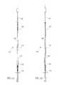
- FIG. 1Ais a front side view of an entire cell tower installation in accordance with the present disclosure.
- FIG. 1Bis a rear side view of an entire cell tower installation in accordance with the present disclosure.
- FIG. 1Cis a partial front side view of the base section of the cell tower with an alternative attachment configuration.
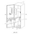
- FIG. 2Ais a partial exploded front perspective view of the base section of the cell tower of FIG. 1A .
- FIG. 2Bis a partial exploded rear perspective view of the base section of the cell tower of FIG. 1B .
- FIG. 2Cillustrates an embodiment of a radio equipment cabinet illustrated in FIG. 2A .
- FIG. 2Dillustrates an embodiment of a battery backup cabinet illustrated in FIG. 2A .
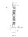
- FIG. 3Ais a partial front side view of the base section of the cell tower of FIG. 2A with the handhole cover in place.
- FIG. 3Bis a partial rear side view of the base section of the cell tower of FIG. 2B with the handhole cover in place.
- FIG. 4is a cross-section view of the twelve-sided cell tower of FIG. 3A taken along the line A-A.
- FIG. 5is a cross-section view of a sixteen-sided cell tower.
- FIG. 6is a perspective view of the top portion of the cell tower of FIG. 1 with the top tower section removed.
- FIG. 7is a perspective view of the top tower portion of the cell tower of FIG. 1 illustrating the placement of electronic components.
- FIG. 8is a close-up view of the mounting assembly used to attach the antenna components to the top of the cell tower of FIG. 1 .
- FIG. 9is a perspective view of an alternative implementation of the top tower portion of the cell tower of FIG. 1 illustrating the placement of electronic components.
- the present disclosureis directed to a cell tower design in which the electronics are integrated into the hollow center of the pole. This integration improves operational characteristics of the cell tower and also eliminates the need for an electronics out-building.
- the overall solutionhelps meet design requirements and zoning requirements for right-of-way (ROW) installation.
- the polealso provides for modular installation of antenna sections at the top of the pole.
- Each antenna systemis contained within a non-conductive canister that protects the antennas from the environment, provides a more environmentally and aesthetically pleasing view, and enables unimpeded wireless transmission and reception from the antennas contained within the canisters.
- the antenna canisters and radio placements and overall layoutare conducive to allowing a multi-carrier pole with all equipment internally contained therein.
- FIG. 1Aillustrates a front side view of a cell tower 100 mounted at a tower location site.
- the cell tower 100comprises a base section 102 , one or more midsections 104 , and a tower top section 106 .
- the cell tower 100is manufactured from steel.
- the cell toweris tapered from a diameter of approximately 33 inches at the base section 102 to approximately 14 inches in diameter at the upper portion of the midsection 104 .
- a monopoleis traditionally caisson-mounted with a reinforced concrete structure buried underground.
- the design of the cell tower 100is a direct-embed pole that requires no additional foundations for mounting.
- the cell tower 100is inserted into the ground much like a telephone pole.
- the ground surface or finished gradeis represented by the reference 108 .
- approximately 10%-15% of the total length of the cell tower 100is below finished grade 108 .
- the base section 102terminates in a mounting flange 101 extending around the periphery of the cell tower 100 at the bottom end.
- a buried portion 103is placed in the ground in a conventional fashion and may be caisson-mounted with reinforced concrete or directly embedded.
- the top of the buried section 103extends slightly above finished grade 108 and terminates in a flange 105 configured to mate with the flange 101 .
- the flanges 101 and 105include a plurality of spaced-apart holes (not shown). The holes are aligned and fasteners 107 , such as nuts and bolts, may be used to join the base section 102 of the cell tower 100 to the buried portion 103 .
- the cell tower 100has a circular cross-section.
- the cross-section of the cell towermay be a polygon, such as a 12-sided polygon or a 16-sided polygon.
- FIG. 4is a cross-section of the cell tower 100 taken at line A-A in FIG. 3A .
- the other drawingsillustrate a 12-sided polygon
- the cell tower 100may be a 16-sided polygon, as illustrated in the cross-section of FIG. 5 .
- the base portion 102 and the midsection 104may be formed by continuous sheet press of steel into the desired polygon shape. The seam may be welded for structural integrity.
- the polygon cross-sectionsare regular polygons such that each side of the polygon is equal in length and the internal angles of the polygon sides are all equal.
- the cell tower 100is approximately 120 feet tall. However, those skilled in the art will appreciate that the tower height can be adjusted to accommodate the particular setting of the cell site location and/or the antenna and radio requirements of the cell tower.
- the midsection 104may be joined to the base section 102 using a conventional slip-joint 109 .
- one section of the cell tower 100is slipped into the next section to form the slip-joint 109 .
- the upper end of the bottom section 102(see FIG. 1A ) is slipped into the lower end of the midsection 104 to form the slip-joint 109 .
- the slip-jointmay provide for an overlap of approximately four feet between the two sections being joined together. Following installation, the pieces may be further joined together by screws or by some other fastening means, such as welding.
- the top section 106is bolted to the top of the midsection 104 , as will be described in greater detail below.
- the base section 102 of the cell tower 100contains a plurality of openings or apertures, sometimes referred to as “handholes.”
- FIG. 2Aillustrates handholes 110 - 112 in the base section 102 .
- the handhole 110provides access to a hollow interior portion 114 of the base section 102 .
- FIG. 2Aillustrates a baseband unit cabinet 134 that contains electronics such as baseband filters, amplifiers, and the like, as well as cell site router equipment.
- the baseband unit cabinet 134may be conveniently pre-assembled and installed as an integrated unit into the interior 114 of the cell tower 100 using the handhole 110 .
- the handhole 112provides access to the interior 114 of the base section 102 for the installation of a battery cabinet 139 .
- cell towerstypically have an array of nickel cadmium (NiCAD) or gel batteries to provide power to the cell tower 100 in the event of a temporary loss of external power.
- NiCADnickel cadmium
- gel batteriesto provide power to the cell tower 100 in the event of a temporary loss of external power.
- the apertures 110 - 112are sized to receive the baseband unit cabinet 134 and the battery cabinet 139 .
- a rack support 116may be welded or fastened to the interior 114 of the base section 102 .
- the rack supports 116are sized to receive and retain equipment, such as the baseband unit cabinet 134 and the battery cabinet 139 . This approach allows the electronic components and back-up battery packs to be pre-assembled offsite and delivered to the tower location site for installation as a unit. This simplifies the installation and maintenance of the cell tower 100 .
- FIG. 2Billustrates handholes 120 - 122 on the rear side of the cell tower 100 opposite the handholes 110 - 112 , respectively.
- the handholes 120 - 122are smaller in size than the handholes 110 - 112 .
- the handholes 110 - 112are sized to receive the electronic equipment while the handholes 120 - 122 provide access to the cabling at the rear of the baseband unit cabinet 134 and battery cabinet 139 .
- the handholes 120 - 122may be smaller in size, similar to handholes 144 - 148 (see FIG. 6 ).
- the handholes 110 - 112 and 120 - 122are surrounded by handhole collars 124 .
- the handhole collars 124improve the structural integrity of the cell tower 100 in areas where the sidewall of the cell tower has been cut to provide the various handholes.
- the handhole collars 124are typically welded to the cell tower 100 .
- a series of handhole covers 126are sized to cover the various handholes 110 - 112 and 120 - 122 .
- the handhole covers 126may include a plurality of ventilation slots 128 .
- the bottom portion of the handhole collars 124may include a cover support lip 130 to retain the bottom portion of the handhole covers 126 for ease in installation.
- the handhole covers 126are attached to the respective handhole collars 124 using security bolts (not shown). In another embodiment, the handhole covers 126 may be affixed to the handhole collars 124 using hinges on one side such that the handhole covers are configured as doors that swing to an open position to provide access to the interior 114 of the cell tower 100 .
- security boltsnot shown
- the handhole covers 126may be affixed to the handhole collars 124 using hinges on one side such that the handhole covers are configured as doors that swing to an open position to provide access to the interior 114 of the cell tower 100 .
- conventional intrusion detection technologymay also be employed with the cell tower 100 to detect unauthorized access to the interior 114 of the cell tower.
- FIG. 2Balso illustrates external power support infrastructure for the cell tower 100 including a power protection cabinet 121 , a disconnect switch 123 , and a power meter 125 . These are commercially available components that need not be described in greater detail herein.
- the power protection cabinet 121 , disconnect switch 123 , and power meter 125are mounted on the external portion of the cell tower 100 via a polarity of mounting holes 127 .
- FIG. 2Cillustrates details of the baseband unit cabinet 134 .
- the interior of the baseband unit cabinet 134includes rack mounts 135 such that electronic equipment may be mounted in conventional electronic equipment racks.
- FIG. 2Calso illustrates baseband electronics 136 , which are commercially available electronic components. Operational details of the baseband electronics 136 are known to those of skill in the art and need not be described herein.
- the rack arrangement of the baseband electronics 136provides for simple installation and removal and maintenance.
- the baseband electronics 136may be installed in the baseband unit cabinet 134 offsite and installed into the cell tower 100 as an integrated unit.
- the cables at the back of the baseband electronics 136are accessible through the handhole 120 , illustrated in FIG. 2B .
- FIG. 135such that electronic equipment may be mounted in conventional electronic equipment racks.
- FIG. 2Calso illustrates baseband electronics 136 , which are commercially available electronic components. Operational details of the baseband electronics 136 are known to those of skill in the art and need not be
- FIG. 2Calso illustrates one or more spare bays 137 configured to receive additional baseband electronics 136 .
- the spare bay 137allows for expansion of services in the cell tower 100 .
- the spare bay 137may be used to provide the baseband electronics 136 for a different cellular network provider.
- FIG. 2also illustrates ventilation slots 128 and a ventilation fan 138 to provide necessary cooling.
- FIG. 2Dillustrates details of the battery cabinet 139 .
- a series of battery modules 141are placed within battery slots 143 inside the battery cabinet 139 .
- FIG. 2Dillustrates four battery modules 141 as well as provisions for spare battery modules.
- the battery cabinet 139also includes ventilation slots 128 and one or more ventilation fans 138 .
- the battery cabinet 139may be conveniently preconfigured offsite to include the necessary number of battery modules 141 .
- the pre-assembled battery cabinet 139may be installed in the cell tower 100 through the handhole 112 (see FIG. 2A ) as an integrated unit. Cabling access to the battery modules 141 are possible via the handhole 122 .
- FIGS. 3A and 3Bare partial front and rear side elevation views, respectively, that illustrate the base section 102 of the cell tower 100 with the handhole covers 126 mounted in place.
- FIG. 3A-3Balso illustrate an optional steel collar 132 fixed to the base section 102 of the cell tower 100 and extending slightly above and slightly below the finished grade 108 .
- the steel collar 132may be welded to the base section 102 to provide greater strength at the point of entry of the cell tower 100 into the ground.
- FIG. 6illustrates the top of the midsection 104 of the cell tower 100 . Illustrated in FIG. 6 are a plurality of handholes 140 - 148 .
- the handholes 140 - 148are provided to assist in the routing and maintenance of cables running from the equipment cabinets in the base section 102 to the radios and antennas on the top section 106 (see FIGS. 1A-1B ) of the cell tower 100 .
- the handholes 140 - 148 illustrated in FIG. 6are configured to correspond to different radio units on the top section 106 of the cell tower 100 .
- the handholes 140 - 142are microwave cable ports that allow a technician access to the cable routing for the microwave antennas, which are mounted to the top section 106 (see FIGS. 7 and 9 ) of the cell tower 100 .
- the handholes 144 - 148are radio cable ports that allow a technician access to the cabling for the cellular antennas and remote radio units (RRUs) in the top section 106 .
- the handholes 144 - 148correspond to the respective sectors used in a typical cell tower.
- a typical cell towerprovides an area of coverage that is broken into sectors. Three sectors is a common cell coverage plan.
- the three handholes 144 - 148can separate the cabling by sector to simplify installation, maintenance and troubleshooting, and replacement.
- the handholes 140 - 148may be surrounded by handhole collars 124 and handhole covers (not shown).
- the uppermost portion of the midsection 104terminates with a flange or mounting member 152 and a plurality of mounting holes 154 .
- the flange 152mates with a portion of the top section 106 of the cell tower 100 and bolts (not shown) are used to fasten the top section to the flange 152 to thereby securely attach the top section 106 of the cell tower 100 .
- FIG. 7provides details of an exemplary embodiment of the top section 106 of the cell tower 100 .
- the top section 106may be implemented as a three inch diameter galvanized steel pipe 150 .
- a bottom flange 160is sized to mate with the flange 152 on the midsection 104 of the cell tower 100 .
- the bottom flange 160may comprise a plurality of holes that align with the holes 154 (see FIG. 6 ) in the flange 152 .
- one flangee.g., the bottom flange 160
- the mounting holes 154 in the flange 152are positioned to align with the studs.
- the top section 106is designed to provide great flexibility in configuration of RRUs and antennas for one or more cellular service providers.
- the top section 106is divided into a microwave portion 162 and a cellular radio portion 164 .
- the microwave radio portion 162is at the very top of the cellular tower 100 and it typically contains two or four microwave antennas.
- FIG. 7only illustrates one microwave antenna 166 .
- the microwave link on the cell tower 100may be used to implement a backhaul or for use as a donor site where cell traffic may be offloaded from one cell tower to another to provide a more balanced load. Operation of the microwave portion 162 of the cell tower 100 is well known in the art and need not be described in greater detail herein.
- the microwave antenna 166is contained within a shroud or canister 168 .
- FIG. 7illustrates a cutaway portion of the shroud 168 to illustrate the mounting of the microwave antenna 166 inside the shroud.
- the shroud 168is manufactured from a non-conductive material that is visually opaque to provide a more esthetically pleasing appearance. The color of the shroud 168 may be selected to match nearby surroundings. While the shroud 168 is visually opaque, it is manufactured from materials selected to have little or no impact on the radio frequency (RF) characteristics of the microwave portion 162 . That is, the shroud 168 will not alter the antenna pattern of the microwave antenna 166 or attenuate the RF signal to/from the microwave antenna.
- RFradio frequency
- the shroud 168may be manufactured from a Kevlar® material.
- the shroud 168may be manufactured using a Gore-Tex® material.
- the shroud 168may be manufactured from a combination of these materials or other materials that provide satisfactory operating characteristics, as described above.
- the shroud 168may be manufactured with a polytetrafluoroethylene membrane, which provides a hydrophobic mesh. This is a flexible material that provides protection for the electronic components, but permits good ventilation and provides a visual barrier.
- the shroud 168may be manufactured from the flexible material, as described above.
- FIG. 7illustrates a top shroud frame 170 and a bottom shroud frame 172 .
- the shroud 168may be attached to the top shroud frame 170 and bottom shroud frame 172 to help maintain its shape and to protect the components from the elements.
- the shroud 168may be manufactured from a stiff material, such as polyvinyl chloride (PVC) material.
- PVCpolyvinyl chloride
- the PVC materialis rigid.
- the top shroud frame 170 and bottom shroud frame 172may be unnecessary.
- the very top of the cell tower 100may include a lightning rod 176 . Operation of the lightning rod 176 is known in the art, and need not be described in greater detail herein.
- the cellular radio portion 164may typically comprise two sets of cellular antennas. As previously discussed, cellular radio antennas may typically be divided into three separate sectors. For the sake of clarity, FIG. 7 illustrates only a single sector antenna 180 and a sector antenna 182 . Typically, the sector antenna 180 would be for one cellular frequency band (e.g., 800 MHz) and the sector antenna 182 would be for a different frequency band (e.g., 1900 MHz).
- the sector antennas 180 - 182are attached to the top section 106 by a plurality of mounting members 184 . The details of the mounting member 184 are illustrated in FIG. 8 . The mounting members 184 may be clamped to the top section 106 at any desired location and orientation by the technician doing an initial installation.
- FIG. 8illustrates a bolt 186 and a nut 188 .
- a plurality of the bolts 186 and nuts 188are used to clamp the radio mounting member 184 to the top section 106 .
- Each radio mounting member 184also has rotatable mounting plates 190 to mate with the respective sector antennas.
- the mounting plates 190may contain screw holes or other conventional means for attaching the sector antennas (e.g., the sector antenna 180 ) to the mounting plate 190 .
- FIG. 7illustrates an RRU 192 for use with the sector antenna 180 .
- a different RRU(not shown) is provided for each of the other sector antennas (not shown) corresponding to the sector antenna 180 .
- FIG. 7also illustrates an RRU 194 designed for operation with the sector antenna 182 .
- a different RRU(not shown) is provided for each of the other sector antennas (not shown) corresponding to the sector antenna 182 .
- the cellular radio portion 164is contained within a single shroud 200 .
- the cellular radio canister 164includes a top shroud frame 202 and a bottom shroud frame 204 .
- the shroud 200may be manufactured of materials similar to that discussed above with respect to the shroud 168 . If the shroud 200 is manufactured of a flexible material, the top shroud frame 202 and bottom shroud frame 204 can serve to maintain rigidity of the shroud 200 and to protect the electronic components from the elements. If the shroud 200 is manufactured from a rigid material, such as PVC, the top shroud frame 202 and bottom shroud frame 204 may serve to at least partially seal the cellular radio portion 164 from the elements.
- FIG. 7illustrates a single shroud 200 for both cellular antennas (e.g., the cellular antenna 180 and the cellular antenna 182 ), it is possible to provide a separate shroud for each cellular antenna). In the example of FIG. 7 , there would be three shrouds corresponding to the microwave portion 162 and two cellular portions 164 , respectively. In another embodiment, the top section 106 could have a single shroud for both the microwave portion 162 and the cellular portion 164 .
- the top section 106 of the cell tower 100can include a multi-band cellular antenna 210 in place of the separate cellular antennas 180 and 182 illustrated in FIG. 7 .
- the cellular portion 164containing multi-band cellular antenna 210 , may be located at the top of the cell tower 100 in place of the microwave portion 162 in FIG. 7 .
- the multi-band cellular antenna 210comprises three sector antennas 212 mounted to a central support.
- the multi-band cellular antenna 210is enclosed within a shroud 214 .
- the shroud 214may be manufactured using any of the techniques described above with respect to the shroud 168 or the shroud 200 illustrated in FIG. 7 .
- the galvanized steel pipe 150(see FIG. 7 ) is replaced by a lattice tower 220 .
- the lattice tower 220is implemented in a triangular shape with three tower legs 222 connected to each other through a series of cross-braces 224 to provide structural rigidity.
- the lattice tower 220is coupled to the bottom flange 160 for mating with the top flange 152 in the manner described above with respect to the embodiment of FIG. 7 .
- the lattice tower 220is surrounded by the shroud 200 in a manner similar to that described above.
- the top shroud frame 202 and bottom shroud frame 204provide structural support and rigidity to the shroud 200 .
- FIG. 9illustrates a plurality of intermediate shroud frames 226 to provide additional support for the shroud 200 along its full length.
- the shroud 200 in the embodiment of FIG. 9may be implemented using any of the techniques described above with respect to the shrouds 168 and 200 illustrated in FIG. 7 .
- a flangesimilar to the flange 152 illustrated in FIG. 6 .
- the flange at the top of the lattice tower 220mates with a flange 230 at the bottom end of an extension pole 232 .
- the microwave antenna 166is mounted on the extension pole 232 .
- the top of the extension pole 232also terminates in a flange (not shown) to mate with a flange at the bottom of the cellular portion 164 .
- the flange mounting techniqueallows greater flexibility in replacing various portions of the top section 106 of the cell tower 100 .
- the RRUs 192 and 194are not illustrated, but may be mounted on the lattice tower 220 within the shroud 200 with cabling (not shown) coupled between the RRUs and the multi-band cellular antenna 210 .
- the top tower section 106can be readily configured to meet the operational requirements of one or more cell service providers.
- the antenna elements, RRUs, and RF filterscan be easily mounted within the protective shrouds.
- the cell tower 100provides for flexible placement of cellular radio components and microwave components. The modular arrangement also permits easy updates and replacement of broken or damaged components.
- the base section 102 of the cell tower 100permits the easy installation, repair, and replacement of the baseband cabinet 134 and battery cabinet 139 .
- any two components herein combined to achieve a particular functionalitycan be seen as “associated with” each other such that the desired functionality is achieved, irrespective of architectures or intermedial components.
- any two components so associatedcan also be viewed as being “operably connected”, or “operably coupled”, to each other to achieve the desired functionality.
Landscapes
- Engineering & Computer Science (AREA)
- Architecture (AREA)
- Civil Engineering (AREA)
- Structural Engineering (AREA)
- Computer Networks & Wireless Communication (AREA)
- Signal Processing (AREA)
- Life Sciences & Earth Sciences (AREA)
- Chemical & Material Sciences (AREA)
- Materials Engineering (AREA)
- Wood Science & Technology (AREA)
- Support Of Aerials (AREA)
Abstract
Description
Claims (31)
Priority Applications (1)
| Application Number | Priority Date | Filing Date | Title |
|---|---|---|---|
| US15/062,709US9698477B1 (en) | 2016-03-07 | 2016-03-07 | Cell tower and method of use |
Applications Claiming Priority (1)
| Application Number | Priority Date | Filing Date | Title |
|---|---|---|---|
| US15/062,709US9698477B1 (en) | 2016-03-07 | 2016-03-07 | Cell tower and method of use |
Publications (1)
| Publication Number | Publication Date |
|---|---|
| US9698477B1true US9698477B1 (en) | 2017-07-04 |
Family
ID=59152454
Family Applications (1)
| Application Number | Title | Priority Date | Filing Date |
|---|---|---|---|
| US15/062,709Expired - Fee RelatedUS9698477B1 (en) | 2016-03-07 | 2016-03-07 | Cell tower and method of use |
Country Status (1)
| Country | Link |
|---|---|
| US (1) | US9698477B1 (en) |
Cited By (35)
| Publication number | Priority date | Publication date | Assignee | Title |
|---|---|---|---|---|
| US20160323146A1 (en)* | 2015-04-14 | 2016-11-03 | ETAK Systems, LLC | Close-out audit systems and methods for cell site installation and maintenance |
| US20180254545A1 (en)* | 2017-03-06 | 2018-09-06 | Commscope Technologies Llc | Modular monopole for wireless communications |
| WO2019043046A1 (en)* | 2017-08-29 | 2019-03-07 | Schreder S.A. | Lamp post with improved cooling |
| WO2019061003A1 (en)* | 2017-09-27 | 2019-04-04 | Elova S.A. | Post for a wireless transmission antenna and method for installing same |
| US10255719B2 (en)* | 2015-04-14 | 2019-04-09 | ETAK Systems, LLC | Systems and methods for satellite data capture for telecommunications site modeling |
| US10390386B2 (en)* | 2016-12-16 | 2019-08-20 | Commscope Technologies Llc | Integrated cell site module for mounting a remote radio unit and radio frequency signal conditioning unit as a single unit |
| US20190277050A1 (en)* | 2018-03-07 | 2019-09-12 | Comptek Technologies, Llc | Utility pole with transparent portion |
| WO2019178502A2 (en) | 2018-03-15 | 2019-09-19 | Dimitrios Lalos | Multi-purpose smart tower |
| BE1026392B1 (en)* | 2018-06-18 | 2020-01-28 | Schreder Sa | IMPROVED COOLING LAMP POST |
| US20200118054A1 (en)* | 2018-10-11 | 2020-04-16 | Bryan Bayges | Pole Network |
| US20200136236A1 (en)* | 2018-10-29 | 2020-04-30 | Commscope Technologies Llc | Perforated door for monopole module and method of mounting same |
| US10790577B2 (en)* | 2017-01-26 | 2020-09-29 | nepsa solutions LLC | Small cell pole and mounting system and methods of use and installation thereof |
| US10950921B2 (en)* | 2016-01-27 | 2021-03-16 | Sabre Industries Inc. | Radio and power pole |
| US10971811B1 (en) | 2020-02-24 | 2021-04-06 | CCS Technologies LLC | 5G membrane radio shroud |
| US11082865B2 (en)* | 2015-04-14 | 2021-08-03 | ETAK Systems, LLC | Systems and methods for coordinating initiation, preparing, vetting, scheduling, constructing, and implementing a small cell implementation |
| US20210320393A1 (en)* | 2020-04-10 | 2021-10-14 | Commscope Technologies Llc | Module for a cellular communications monopole |
| US11201382B2 (en) | 2020-04-01 | 2021-12-14 | Comptek Technologies, Llc | Ducted antenna housing for small cell pole |
| US11251520B2 (en) | 2020-02-24 | 2022-02-15 | CCS Technologies LLC | 5G membrane radio shroud |
| US11362410B2 (en)* | 2019-06-07 | 2022-06-14 | Commscope Technologies Llc | Mounting configuration for small cell antenna assembly |
| CN114856283A (en)* | 2022-06-01 | 2022-08-05 | 中国通信建设集团设计院有限公司 | Design method of integrated energy-saving communication tower |
| US11469488B2 (en) | 2020-04-01 | 2022-10-11 | Comptek Technologies, Llc | Thermal management system for modular antenna housing |
| EP4092224A1 (en)* | 2021-05-19 | 2022-11-23 | Allied Consultant Engineering Ltd | Structural support sleeve |
| US11532866B2 (en)* | 2020-06-24 | 2022-12-20 | Dish Wireless L.L.C. | Cellular base station ground component mounting system |
| WO2023039290A3 (en)* | 2021-09-13 | 2023-04-20 | Dimitrios Lalos | Vertically stacked, integratable, multipurpose platform configurable as wireless base stations |
| US20230187817A1 (en)* | 2020-05-01 | 2023-06-15 | Dish Wireless L.L.C. | Cellular antenna enclosures |
| USD1002599S1 (en) | 2022-02-24 | 2023-10-24 | Comptek Technologies, Llc | Wireless access tower |
| USD1002600S1 (en) | 2022-02-24 | 2023-10-24 | Comptek Technologies, Llc | Wireless antenna shroud |
| US11817624B1 (en)* | 2021-10-01 | 2023-11-14 | Gregg Ehresmann | Ventilation apparatus for a containment of antenna elements |
| US11817614B2 (en) | 2021-06-09 | 2023-11-14 | Comptek Technologies Llc | Wireless access point thermal management |
| USD1006801S1 (en) | 2022-02-24 | 2023-12-05 | Comptek Technologies, Llc | Wireless access point support pole |
| US11909093B2 (en) | 2021-06-09 | 2024-02-20 | Comptek Technologies Llc | Wireless access point support spire and dividers |
| US20240147653A1 (en)* | 2022-11-02 | 2024-05-02 | Quanta Computer Inc. | Smart pole assembly and cabinet for server |
| US12035486B1 (en) | 2022-07-25 | 2024-07-09 | Manufacturing Resources International, Inc. | Electronic display assembly with fabric panel communications box |
| US20240235036A9 (en)* | 2022-10-19 | 2024-07-11 | Dish Wireless L.L.C. | Monopalm collocation design |
| EP4545734A1 (en)* | 2023-10-26 | 2025-04-30 | Vantage Towers, S.L.U. | Tower structure for telecommunications equipment |
Citations (7)
| Publication number | Priority date | Publication date | Assignee | Title |
|---|---|---|---|---|
| US5611176A (en)* | 1994-03-02 | 1997-03-18 | Juengert; Robert P. | Antenna support structure |
| US6173537B1 (en)* | 1993-12-15 | 2001-01-16 | Mafi Ab | Antenna tower |
| US6222503B1 (en)* | 1997-01-10 | 2001-04-24 | William Gietema | System and method of integrating and concealing antennas, antenna subsystems and communications subsystems |
| US20040174317A1 (en)* | 2003-03-03 | 2004-09-09 | Andrew Corporation | Low visual impact monopole tower for wireless communications |
| US20060232478A1 (en)* | 2005-04-18 | 2006-10-19 | Wistron Neweb Corp. | Planar monopole antennas |
| US20100026604A1 (en)* | 2009-09-14 | 2010-02-04 | Caldwell Steven R | Methods of modifying erect concealed antenna towers and associated modified towers and devices therefor |
| US8125403B2 (en)* | 2006-03-20 | 2012-02-28 | Telefonaktiebolaget L M Ericsson (Publ) | Tubular telecom tower |
- 2016
- 2016-03-07USUS15/062,709patent/US9698477B1/ennot_activeExpired - Fee Related
Patent Citations (7)
| Publication number | Priority date | Publication date | Assignee | Title |
|---|---|---|---|---|
| US6173537B1 (en)* | 1993-12-15 | 2001-01-16 | Mafi Ab | Antenna tower |
| US5611176A (en)* | 1994-03-02 | 1997-03-18 | Juengert; Robert P. | Antenna support structure |
| US6222503B1 (en)* | 1997-01-10 | 2001-04-24 | William Gietema | System and method of integrating and concealing antennas, antenna subsystems and communications subsystems |
| US20040174317A1 (en)* | 2003-03-03 | 2004-09-09 | Andrew Corporation | Low visual impact monopole tower for wireless communications |
| US20060232478A1 (en)* | 2005-04-18 | 2006-10-19 | Wistron Neweb Corp. | Planar monopole antennas |
| US8125403B2 (en)* | 2006-03-20 | 2012-02-28 | Telefonaktiebolaget L M Ericsson (Publ) | Tubular telecom tower |
| US20100026604A1 (en)* | 2009-09-14 | 2010-02-04 | Caldwell Steven R | Methods of modifying erect concealed antenna towers and associated modified towers and devices therefor |
Cited By (53)
| Publication number | Priority date | Publication date | Assignee | Title |
|---|---|---|---|---|
| US9947135B2 (en)* | 2015-04-14 | 2018-04-17 | ETAK Systems, LLC | Close-out audit systems and methods for cell site installation and maintenance |
| US20160323146A1 (en)* | 2015-04-14 | 2016-11-03 | ETAK Systems, LLC | Close-out audit systems and methods for cell site installation and maintenance |
| US11082865B2 (en)* | 2015-04-14 | 2021-08-03 | ETAK Systems, LLC | Systems and methods for coordinating initiation, preparing, vetting, scheduling, constructing, and implementing a small cell implementation |
| US10255719B2 (en)* | 2015-04-14 | 2019-04-09 | ETAK Systems, LLC | Systems and methods for satellite data capture for telecommunications site modeling |
| US10950921B2 (en)* | 2016-01-27 | 2021-03-16 | Sabre Industries Inc. | Radio and power pole |
| US10390386B2 (en)* | 2016-12-16 | 2019-08-20 | Commscope Technologies Llc | Integrated cell site module for mounting a remote radio unit and radio frequency signal conditioning unit as a single unit |
| US10790577B2 (en)* | 2017-01-26 | 2020-09-29 | nepsa solutions LLC | Small cell pole and mounting system and methods of use and installation thereof |
| US20220384936A1 (en)* | 2017-03-06 | 2022-12-01 | Commscope Technologies Llc | Modular monopole for wireless communications |
| US20180254545A1 (en)* | 2017-03-06 | 2018-09-06 | Commscope Technologies Llc | Modular monopole for wireless communications |
| US11417943B2 (en)* | 2017-03-06 | 2022-08-16 | Commscope Technologies Llc | Modular monopole for wireless communications |
| US12015194B2 (en)* | 2017-03-06 | 2024-06-18 | Commscope Technologies Llc | Modular monopole for wireless communications |
| WO2019043046A1 (en)* | 2017-08-29 | 2019-03-07 | Schreder S.A. | Lamp post with improved cooling |
| WO2019061003A1 (en)* | 2017-09-27 | 2019-04-04 | Elova S.A. | Post for a wireless transmission antenna and method for installing same |
| US10947751B2 (en)* | 2018-03-07 | 2021-03-16 | Comptek Technologies, Llc | Utility pole with transparent portion |
| US20190277050A1 (en)* | 2018-03-07 | 2019-09-12 | Comptek Technologies, Llc | Utility pole with transparent portion |
| EP3766127A4 (en)* | 2018-03-15 | 2021-12-01 | Dimitrios Lalos | Multi-purpose smart tower |
| WO2019178502A2 (en) | 2018-03-15 | 2019-09-19 | Dimitrios Lalos | Multi-purpose smart tower |
| US11532876B2 (en) | 2018-03-15 | 2022-12-20 | Dimitrios Lalos | Multi-purpose smart tower |
| BE1026392B1 (en)* | 2018-06-18 | 2020-01-28 | Schreder Sa | IMPROVED COOLING LAMP POST |
| US20200118054A1 (en)* | 2018-10-11 | 2020-04-16 | Bryan Bayges | Pole Network |
| US10853752B2 (en)* | 2018-10-11 | 2020-12-01 | Bryan Bayges | Pole network |
| US12003016B2 (en)* | 2018-10-29 | 2024-06-04 | Commscope Technologies Llc | Perforated door for monopole module and method of mounting same |
| US20200136236A1 (en)* | 2018-10-29 | 2020-04-30 | Commscope Technologies Llc | Perforated door for monopole module and method of mounting same |
| US11784390B2 (en) | 2019-06-07 | 2023-10-10 | Commscope Technologies Llc | Mounting configuration for small cell antenna assembly |
| US11362410B2 (en)* | 2019-06-07 | 2022-06-14 | Commscope Technologies Llc | Mounting configuration for small cell antenna assembly |
| US11251520B2 (en) | 2020-02-24 | 2022-02-15 | CCS Technologies LLC | 5G membrane radio shroud |
| US10971811B1 (en) | 2020-02-24 | 2021-04-06 | CCS Technologies LLC | 5G membrane radio shroud |
| US11469488B2 (en) | 2020-04-01 | 2022-10-11 | Comptek Technologies, Llc | Thermal management system for modular antenna housing |
| US11664572B2 (en)* | 2020-04-01 | 2023-05-30 | Comptek Technologies Llc | Ducted antenna housing for small cell pole |
| US11201382B2 (en) | 2020-04-01 | 2021-12-14 | Comptek Technologies, Llc | Ducted antenna housing for small cell pole |
| US20220166123A1 (en)* | 2020-04-01 | 2022-05-26 | Comptek Technologies, Llc | Ducted antenna housing for small cell pole |
| US20210320393A1 (en)* | 2020-04-10 | 2021-10-14 | Commscope Technologies Llc | Module for a cellular communications monopole |
| US11688925B2 (en)* | 2020-04-10 | 2023-06-27 | Commscope Technologies Llc | Module for a cellular communications monopole |
| US12107320B2 (en) | 2020-04-10 | 2024-10-01 | Commscope Technologies Llc | Module for a cellular communications monopole |
| US20230187817A1 (en)* | 2020-05-01 | 2023-06-15 | Dish Wireless L.L.C. | Cellular antenna enclosures |
| US11967755B2 (en)* | 2020-05-01 | 2024-04-23 | Dish Wireless L.L.C. | Cellular antenna enclosures |
| US11532866B2 (en)* | 2020-06-24 | 2022-12-20 | Dish Wireless L.L.C. | Cellular base station ground component mounting system |
| EP4092224A1 (en)* | 2021-05-19 | 2022-11-23 | Allied Consultant Engineering Ltd | Structural support sleeve |
| US11909093B2 (en) | 2021-06-09 | 2024-02-20 | Comptek Technologies Llc | Wireless access point support spire and dividers |
| US11817614B2 (en) | 2021-06-09 | 2023-11-14 | Comptek Technologies Llc | Wireless access point thermal management |
| WO2023039290A3 (en)* | 2021-09-13 | 2023-04-20 | Dimitrios Lalos | Vertically stacked, integratable, multipurpose platform configurable as wireless base stations |
| US11817624B1 (en)* | 2021-10-01 | 2023-11-14 | Gregg Ehresmann | Ventilation apparatus for a containment of antenna elements |
| USD1002599S1 (en) | 2022-02-24 | 2023-10-24 | Comptek Technologies, Llc | Wireless access tower |
| USD1006801S1 (en) | 2022-02-24 | 2023-12-05 | Comptek Technologies, Llc | Wireless access point support pole |
| USD1002600S1 (en) | 2022-02-24 | 2023-10-24 | Comptek Technologies, Llc | Wireless antenna shroud |
| CN114856283A (en)* | 2022-06-01 | 2022-08-05 | 中国通信建设集团设计院有限公司 | Design method of integrated energy-saving communication tower |
| CN114856283B (en)* | 2022-06-01 | 2023-07-18 | 中国通信建设集团设计院有限公司 | Design method of integrated energy-saving communication tower |
| US12035486B1 (en) | 2022-07-25 | 2024-07-09 | Manufacturing Resources International, Inc. | Electronic display assembly with fabric panel communications box |
| US12108546B1 (en) | 2022-07-25 | 2024-10-01 | Manufacturing Resources International, Inc. | Electronic display assembly with fabric panel communications box |
| US20240235036A9 (en)* | 2022-10-19 | 2024-07-11 | Dish Wireless L.L.C. | Monopalm collocation design |
| US20240147653A1 (en)* | 2022-11-02 | 2024-05-02 | Quanta Computer Inc. | Smart pole assembly and cabinet for server |
| US12232292B2 (en)* | 2022-11-02 | 2025-02-18 | Quanta Computer Inc. | Smart pole assembly and cabinet for server |
| EP4545734A1 (en)* | 2023-10-26 | 2025-04-30 | Vantage Towers, S.L.U. | Tower structure for telecommunications equipment |
Similar Documents
| Publication | Publication Date | Title |
|---|---|---|
| US9698477B1 (en) | Cell tower and method of use | |
| US10950921B2 (en) | Radio and power pole | |
| US10930996B2 (en) | Integrated cell site sector | |
| US10790577B2 (en) | Small cell pole and mounting system and methods of use and installation thereof | |
| US5880701A (en) | Enclosed wireless telecommunications antenna | |
| US10347979B1 (en) | Apparatus, method, and system for RF-transmissive access panels for elevated and shrouded mobile network components | |
| US10944149B2 (en) | Concealed antenna node | |
| US8789261B2 (en) | Communications vehicle | |
| US7339549B2 (en) | Universal mounting assembly | |
| US20190221913A1 (en) | Small modular cell pole | |
| KR20220023422A (en) | Screen fence for the base station antenna | |
| US20220311122A1 (en) | Modules for cellular base stations and bracket assemblies for mounting same | |
| WO2022187301A1 (en) | Enclosures for cellular base station assemblies and bracket assemblies for mounting same | |
| CN104265046A (en) | Novel base station communication signal launching tower | |
| US7205956B1 (en) | Structural waveguide formed in a leg of an antenna tower and method of use | |
| CA2236397A1 (en) | Wireless telecommunication antenna mount | |
| US20120299796A1 (en) | Module for Carrying Antennas of a Telecommunication System and Antenna Mast Arrangement | |
| CN105720353A (en) | Antenna structure for wireless network coverage manhole cover and installation method of antenna structure | |
| US20240275018A1 (en) | Antenna support system | |
| CN211350972U (en) | Square column type antenna housing | |
| US6177630B1 (en) | Equipment installation concrete pad having integrated equipotential grounding plane and method for installing equipment using same | |
| CN113099733A (en) | Metropolitan area cellular antenna assemblies and pole assemblies and base stations including the same | |
| CN215717676U (en) | Traffic monitoring rod | |
| CN104499760A (en) | Novel fast-installation type polyhedral base station tower | |
| RU2757647C1 (en) | Smart module |
Legal Events
| Date | Code | Title | Description |
|---|---|---|---|
| AS | Assignment | Owner name:MOBILITIE MANAGEMENT, LLC, CALIFORNIA Free format text:ASSIGNMENT OF ASSIGNORS INTEREST;ASSIGNORS:JABARA, GARY B.;KARMIS, CHRISTOS;CALIENTO, JASON;AND OTHERS;SIGNING DATES FROM 20160226 TO 20160302;REEL/FRAME:037911/0410 | |
| AS | Assignment | Owner name:MOBILITIE, LLC, CALIFORNIA Free format text:ASSIGNMENT OF ASSIGNORS INTEREST;ASSIGNOR:MOBILITIE MANAGEMENT, LLC;REEL/FRAME:040950/0970 Effective date:20170105 | |
| STCF | Information on status: patent grant | Free format text:PATENTED CASE | |
| AS | Assignment | Owner name:CIT BANK, N.A., AS ADMINISTRATIVE AGENT, NEW JERSE Free format text:SECURITY INTEREST;ASSIGNOR:MOBILITIE, LLC;REEL/FRAME:050797/0058 Effective date:20191018 Owner name:CIT BANK, N.A., AS ADMINISTRATIVE AGENT, NEW JERSEY Free format text:SECURITY INTEREST;ASSIGNOR:MOBILITIE, LLC;REEL/FRAME:050797/0058 Effective date:20191018 | |
| FEPP | Fee payment procedure | Free format text:ENTITY STATUS SET TO UNDISCOUNTED (ORIGINAL EVENT CODE: BIG.); ENTITY STATUS OF PATENT OWNER: LARGE ENTITY | |
| FEPP | Fee payment procedure | Free format text:ENTITY STATUS SET TO SMALL (ORIGINAL EVENT CODE: SMAL); ENTITY STATUS OF PATENT OWNER: SMALL ENTITY | |
| MAFP | Maintenance fee payment | Free format text:PAYMENT OF MAINTENANCE FEE, 4TH YR, SMALL ENTITY (ORIGINAL EVENT CODE: M2551); ENTITY STATUS OF PATENT OWNER: SMALL ENTITY Year of fee payment:4 | |
| AS | Assignment | Owner name:MOBILITIE, LLC, CALIFORNIA Free format text:RELEASE BY SECURED PARTY;ASSIGNOR:CIT BANK, N.A., AS ADMINISTRATIVE AGENT;REEL/FRAME:057698/0335 Effective date:20210930 | |
| AS | Assignment | Owner name:IP INVESTEMENT HOLDINGS, LLC, CALIFORNIA Free format text:ASSIGNMENT OF ASSIGNORS INTEREST;ASSIGNOR:MOBILITIE, LLC;REEL/FRAME:057972/0773 Effective date:20210928 | |
| FEPP | Fee payment procedure | Free format text:MAINTENANCE FEE REMINDER MAILED (ORIGINAL EVENT CODE: REM.); ENTITY STATUS OF PATENT OWNER: SMALL ENTITY | |
| LAPS | Lapse for failure to pay maintenance fees | Free format text:PATENT EXPIRED FOR FAILURE TO PAY MAINTENANCE FEES (ORIGINAL EVENT CODE: EXP.); ENTITY STATUS OF PATENT OWNER: SMALL ENTITY | |
| STCH | Information on status: patent discontinuation | Free format text:PATENT EXPIRED DUE TO NONPAYMENT OF MAINTENANCE FEES UNDER 37 CFR 1.362 | |
| FP | Lapsed due to failure to pay maintenance fee | Effective date:20250704 |