US9696735B2 - Context adaptive cool-to-dry feature for HVAC controller - Google Patents
Context adaptive cool-to-dry feature for HVAC controllerDownload PDFInfo
- Publication number
- US9696735B2 US9696735B2US13/871,746US201313871746AUS9696735B2US 9696735 B2US9696735 B2US 9696735B2US 201313871746 AUS201313871746 AUS 201313871746AUS 9696735 B2US9696735 B2US 9696735B2
- Authority
- US
- United States
- Prior art keywords
- humidity
- enclosure
- threshold
- temperature
- thermostat
- Prior art date
- Legal status (The legal status is an assumption and is not a legal conclusion. Google has not performed a legal analysis and makes no representation as to the accuracy of the status listed.)
- Active, expires
Links
Images


Classifications
- G—PHYSICS
- G05—CONTROLLING; REGULATING
- G05D—SYSTEMS FOR CONTROLLING OR REGULATING NON-ELECTRIC VARIABLES
- G05D27/00—Simultaneous control of variables covered by two or more of main groups G05D1/00 - G05D25/00
- G05D27/02—Simultaneous control of variables covered by two or more of main groups G05D1/00 - G05D25/00 characterised by the use of electric means
- G—PHYSICS
- G05—CONTROLLING; REGULATING
- G05D—SYSTEMS FOR CONTROLLING OR REGULATING NON-ELECTRIC VARIABLES
- G05D22/00—Control of humidity
- G05D22/02—Control of humidity characterised by the use of electric means
- G—PHYSICS
- G05—CONTROLLING; REGULATING
- G05D—SYSTEMS FOR CONTROLLING OR REGULATING NON-ELECTRIC VARIABLES
- G05D23/00—Control of temperature
- G05D23/19—Control of temperature characterised by the use of electric means
- G05D23/1902—Control of temperature characterised by the use of electric means characterised by the use of a variable reference value
- F—MECHANICAL ENGINEERING; LIGHTING; HEATING; WEAPONS; BLASTING
- F24—HEATING; RANGES; VENTILATING
- F24F—AIR-CONDITIONING; AIR-HUMIDIFICATION; VENTILATION; USE OF AIR CURRENTS FOR SCREENING
- F24F3/00—Air-conditioning systems in which conditioned primary air is supplied from one or more central stations to distributing units in the rooms or spaces where it may receive secondary treatment; Apparatus specially designed for such systems
- F24F3/12—Air-conditioning systems in which conditioned primary air is supplied from one or more central stations to distributing units in the rooms or spaces where it may receive secondary treatment; Apparatus specially designed for such systems characterised by the treatment of the air otherwise than by heating and cooling
- F24F3/14—Air-conditioning systems in which conditioned primary air is supplied from one or more central stations to distributing units in the rooms or spaces where it may receive secondary treatment; Apparatus specially designed for such systems characterised by the treatment of the air otherwise than by heating and cooling by humidification; by dehumidification
- F24F3/1405—Air-conditioning systems in which conditioned primary air is supplied from one or more central stations to distributing units in the rooms or spaces where it may receive secondary treatment; Apparatus specially designed for such systems characterised by the treatment of the air otherwise than by heating and cooling by humidification; by dehumidification in which the humidity of the air is exclusively affected by contact with the evaporator of a closed-circuit cooling system or heat pump circuit
Definitions
- This patent specificationrelates to systems and methods for the monitoring and control of energy-consuming systems or other resource-consuming systems. More particularly, this patent specification relates to control units that govern the operation of energy-consuming systems, household devices, or other resource-consuming systems, including methods for activating electronic displays for thermostats that govern the operation of heating, ventilation, and air conditioning (HVAC) systems.
- HVACheating, ventilation, and air conditioning
- thermostatsused a bimetallic strip to sense temperature and respond to temperature changes in the room. The movement of the bimetallic strip was used to directly open and close an electrical circuit. Power was delivered to an electromechanical actuator, usually relay or contactor in the HVAC equipment whenever the contact was closed to provide heating and/or cooling to the controlled space. Since these thermostats did not require electrical power to operate, the wiring connections were very simple. Only one wire connected to the transformer and another wire connected to the load. Typically, a 24 VAC power supply transformer, the thermostat, and 24 VAC HVAC equipment relay were all connected in a loop with each device having only two required external connections.
- thermostatsWhen electronics began to be used in thermostats, the fact that the thermostat was not directly wired to both sides of the transformer for its power source created a problem. This meant that the thermostat had to be hardwired directly from the system transformer. Direct hardwiring a common “C” wire from the transformer to the electronic thermostat may be very difficult and costly.
- thermostatsBecause many households do not have a direct wire from the system transformer (such as a “C” wire), some thermostats have been designed to derive power from the transformer through the equipment load.
- the methods for powering an electronic thermostat from the transformer with a single direct wire connection to the transformerare called “power stealing” or “power sharing” methods.
- the thermostat“steals,” “shares,” or “harvests” its power during the “OFF” periods of the heating or cooling system by allowing a small amount of current to flow through it into the load coil below the load coil's response threshold (even at maximum transformer output voltage).
- the thermostatdraws power by allowing a small voltage drop across itself.
- thermostats with power stealing capabilityinclude the Honeywell T8600, Honeywell T8400C, and the Emerson Model 1F97-0671. However, these systems do not have power storage means and therefore must always rely on power stealing.
- thermostatsmay have more advanced environmental control capabilities that can save energy while also keeping occupants comfortable. To do this, these thermostats require more information from the occupants as well as the environments where the thermostats are located. These thermostats may also be capable of connection to computer networks, including both local area networks (or other “private” networks) and wide area networks such as the Internet (or other “public” networks), in order to obtain current and forecasted outside weather data, cooperate in so-called demand-response programs (e.g., automatic conformance with power alerts that may be issued by utility companies during periods of extreme weather), enable users to have remote access and/or control thereof through their network-connected device (e.g., smartphone, tablet computer, PC-based web browser), and other advanced functionalities that may require network connectivity.
- network-connected devicee.g., smartphone, tablet computer, PC-based web browser
- a thermostatmay include a housing, a user interface, one or more temperature sensors, each of the one or more temperature sensors being configured to provide temperature sensor measurements, a humidity sensor configured to provide humidity sensor measurements, an occupancy sensing system that characterizes an occupancy status of an enclosure in which the thermostat is installed from among a plurality of possible occupancy statuses including an occupied state and an away state; and a processing system disposed within the housing.
- the processing systemmay be configured to be in operative communication with the one or more temperature sensors to receive the temperature sensor measurements.
- the processing systemmay be configured to be in operative communication with one or more input devices including the user interface for determining a setpoint temperature.
- the processing systemmay be configured to be in still further operative communication with a heating, ventilation, and air conditioning (HVAC) system to control the HVAC system based at least in part on the setpoint temperature and the temperature sensor measurements.
- HVACheating, ventilation, and air conditioning
- the processing systemmay also be configured to operate in conjunction with the occupancy sensing system to provide an occupancy-status-sensitive automated dehumidification feature comprising: (i) an occupied-state automated dehumidification algorithm designed to operate according to combined comfort-and-humidity criteria characterized in that when the humidity sensor measurements are above a first humidity threshold, and the temperature sensor measurements are below the setpoint temperature, a cooling function of the HVAC system may operate in order to reduce a humidity level in the enclosure until a first set of conditions are met; and (ii) an away-state automated dehumidification algorithm designed to operate according to away-humidity criteria characterized in that when the humidity sensor measurements are above a second humidity threshold, and the temperature sensor measurements are below the setpoint temperature, the cooling function of the HVAC system
- a method of dehumidifying an enclosure using a cooling function of an HVAC systemmay include characterizing, using an occupancy sensing system of a thermostat, an occupancy status of the enclosure, the occupancy status being selected from among a plurality of possible occupancy statuses including an occupied state and an away state.
- the methodmay also include processing humidity sensor measurements provided by a humidity sensor of the thermostat.
- the thermostatmay include a housing, a user interface, one or more temperature sensors, each of the one or more temperature sensors being configured to provide temperature sensor measurements, the humidity sensor, the occupancy sensing system, and a processing system disposed within the housing.
- the processing systemmay be configured to be in operative communication with the one or more temperature sensors to receive the temperature sensor measurements.
- the processing systemmay be configured to be in operative communication with one or more input devices including the user interface for determining a setpoint temperature.
- the processing systemmay be configured to be in still further operative communication with a heating, ventilation, and air conditioning (HVAC) system to control the HVAC system based at least in part on the setpoint temperature and the temperature sensor measurements.
- HVACheating, ventilation, and air conditioning
- the methodmay additionally include operating, using a processing system of the thermostat, an occupancy-status-sensitive automated dehumidification feature.
- This featuremay include (i) an occupied-state automated dehumidification algorithm designed to operate according to combined comfort-and-humidity criteria characterized in that when the humidity sensor measurements are above a first humidity threshold, and the temperature sensor measurements are below the setpoint temperature, a cooling function of the HVAC system may operate in order to reduce a humidity level in the enclosure until a first set of conditions are met; and (ii) an away-state automated dehumidification algorithm designed to operate according to away-humidity criteria characterized in that when the humidity sensor measurements are above a second humidity threshold, and the temperature sensor measurements are below the setpoint temperature, the cooling function of the HVAC system may operate in order to reduce the humidity level in the enclosure until a second set of conditions are met.
- a thermostatmay include one or more temperature sensors that provides temperature sensor measurements, a humidity sensor that provides humidity sensor measurements, an occupancy sensing system that may be used to characterize an occupancy status of an enclosure in which the thermostat is installed from among a plurality of possible occupancy statuses including an occupied state and an away state; and a processing system.
- the processing systemmay be configured to activate a cooling function of an HVAC system to reduce a humidity level in the enclosure based on a first set of conditions when the occupancy status is in the occupied state, or based on a second set of conditions when the occupancy status is in the away state.
- FIG. 1illustrates a perspective view of a thermostat, according to one embodiment.
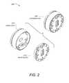
- FIG. 2illustrates an exploded perspective view of a thermostat having a head unit and the backplate, according to one embodiment.
- FIG. 3Aillustrates an exploded perspective view of a head unit with respect to its primary components, according to one embodiment.
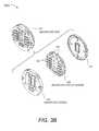
- FIG. 3Billustrates an exploded perspective view of a backplate with respect to its primary components, according to one embodiment.
- FIG. 4Aillustrates a simplified functional block diagram for a head unit, according to one embodiment.
- FIG. 4Billustrates a simplified functional block diagram for a backplate, according to one embodiment.
- FIG. 5illustrates a simplified circuit diagram of a system for managing the power consumed by a thermostat, according to one embodiment.
- FIG. 6illustrates various views of an exemplary thermostat, according to some embodiments.
- FIG. 7illustrates a graph of humidity levels for thermostat devices in Florida during the month of August 2012.
- FIG. 8illustrates a flowchart of a method for reducing a humidity level in an enclosure using a cooling function, according to some embodiments.
- FIG. 9illustrates a flowchart of a method for turning on the long-term away state, according to some embodiments.
- FIG. 10illustrates a graph of multiple dehumidification cycles using backoff intervals, according to some embodiments.
- FIG. 11illustrates a graph of a determined number of dehumidification cycles followed by a longer backoff interval, according to some embodiments.
- FIG. 12Aillustrates a user interface of a thermostat for enabling the auto dehumidification feature, according to some embodiments.
- FIG. 12Billustrates a user interface of a thermostat providing additional information regarding the auto dehumidification feature, according to some embodiments.
- FIG. 13illustrates a user interface of a user device for activating the auto dehumidification feature, according to some embodiments.
- FIG. 14illustrates a user interface of a user device for assessing the efficiency of an auto dehumidification feature, according to some embodiments.
- FIG. 15Aillustrates a user interface of a thermostat indicating that the cooling function is operating as part of the auto dehumidification feature.
- FIG. 15Billustrates a user interface of a thermostat indicating that the cooling function may be operating as part of the auto dehumidification feature while the thermostat is in the away state.
- FIG. 15Cillustrates a user interface of a thermostat indicating that the cooling function may be operating as part of the auto dehumidification feature while the thermostat is in the auto-away state.
- FIG. 15Dillustrates a user interface of a thermostat indicating that the cooling function may be operating as a part of the auto dehumidification feature while the thermostat is in the long-term away state.
- thermostatsaccording to one or more of the preferred embodiments are applicable for a wide variety of enclosures having one or more HVAC systems including, without limitation, duplexes, townhomes, multi-unit apartment buildings, hotels, retail stores, office buildings, and industrial buildings.
- VSCU unitsversatile sensing and control units
- each VSCU unitbeing configured and adapted to provide sophisticated, customized, energy-saving HVAC control functionality while at the same time being visually appealing, non-intimidating, and easy to use.
- thermostatis used herein below to represent a particular type of VSCU unit (Versatile Sensing and Control) that is particularly applicable for HVAC control in an enclosure.
- thermostatand “VSCU unit” may be seen as generally interchangeable for the contexts of HVAC control of an enclosure, it is within the scope of the present teachings for each of the embodiments herein to be applied to VSCU units having control functionality over measurable characteristics other than temperature (e.g., pressure, flow rate, height, position, velocity, acceleration, capacity, power, loudness, brightness) for any of a variety of different control systems involving the governance of one or more measurable characteristics of one or more physical systems, and/or the governance of other energy or resource consuming systems such as water usage systems, air usage systems, systems involving the usage of other natural resources, and systems involving the usage of various other forms of energy.
- measurable characteristics other than temperaturee.g., pressure, flow rate, height, position, velocity, acceleration, capacity, power, loudness, brightness
- FIGS. 1-5 and the descriptions in relation theretoprovide exemplary embodiments of thermostat hardware and/or software that can be used to implement the specific embodiments of the appended claims.
- This thermostat hardware and/or softwareis not meant to be limiting, and is presented to provide an enabling disclosure.
- FIG. 1illustrates a perspective view of a thermostat 100 , according to one embodiment.
- the thermostat 100can be controlled by at least two types of user input, the first being a rotation of the outer ring 112 , and the second being an inward push on an outer cap 108 until an audible and/or tactile “click” occurs.
- these two types of user inputsmay be referred to as “manipulating” the thermostat.
- manipulating the thermostatmay also include pressing keys on a keypad, voice recognition commands, and/or any other type of input that can be used to change or adjust settings on the thermostat 100 .
- the outer cap 108can comprise an assembly that includes the outer ring 112 , a cover 114 , an electronic display 116 , and a metallic portion 124 .
- Each of these elements, or the combination of these elementsmay be referred to as a “housing” for the thermostat 100 .
- each of these elements, or the combination of these elementsmay also form a user interface.
- the user interfacemay specifically include the electronic display 116 .
- the user interface 116may be said to operate in an active display mode.
- the active display modemay include providing a backlight for the electronic display 116 .
- the active display modemay increase the intensity and/or light output of the electronic display 116 such that a user can easily see displayed settings of the thermostat 100 , such as a current temperature, a setpoint temperature, an HVAC function, and/or the like.
- the active display modemay be contrasted with an inactive display mode (not shown).
- the inactive display modecan disable a backlight, reduce the amount of information displayed, lessen the intensity of the display, and/or altogether turn off the electronic display 116 , depending on the embodiment.
- the active display mode and the inactive display mode of the electronic display 116may also or instead be characterized by the relative power usage of each mode.
- the active display modemay generally require substantially more electrical power than the inactive display mode.
- different operating modes of the electronic display 116may instead be characterized completely by their power usage.
- the different operating modes of the electronic display 116may be referred to as a first mode and a second mode, where the user interface requires more power when operating in the first mode than when operating in the second mode.
- the electronic display 116may comprise a dot-matrix layout (individually addressable) such that arbitrary shapes can be generated, rather than being a segmented layout. According to some embodiments, a combination of dot-matrix layout and segmented layout is employed. According to some embodiments, electronic display 116 may be a backlit color liquid crystal display (LCD). An example of information displayed on the electronic display 116 is illustrated in FIG. 1 , and includes central numerals 120 that are representative of a current setpoint temperature. According to some embodiments, metallic portion 124 can have a number of slot-like openings so as to facilitate the use of a sensors 130 , such as a passive infrared motion sensor (PIR), mounted beneath the slot-like openings.
- PIRpassive infrared motion sensor
- the thermostat 100can include additional components, such as a processing system 160 , display driver 164 , and a wireless communications system 166 .
- the processing system 160can adapted or configured to cause the display driver 164 to cause the electronic display 116 to display information to the user.
- the processing system 160can also be configured to receive user input via the rotatable ring 112 .
- These additional components, including the processing system 160can be enclosed within the housing, as displayed in FIG. 1 . These additional components are described in further detail herein below.
- the processing system 160is capable of carrying out the governance of the thermostat's operation.
- processing system 160can be further programmed and/or configured to maintain and update a thermodynamic model for the enclosure in which the HVAC system is installed.
- the wireless communications system 166can be used to communicate with devices such as personal computers, remote servers, handheld devices, smart phones, and/or other thermostats or HVAC system components. These communications can be peer-to-peer communications, communications through one or more servers located on a private network, or and/or communications through a cloud-based service.
- occupancy informationcan be a used in generating an effective and efficient scheduled program.
- an active proximity sensor 170 Acan be provided to detect an approaching user by infrared light reflection
- an ambient light sensor 170 Bcan be provided to sense visible light.
- the proximity sensor 170 Acan be used in conjunction with a plurality of other sensors to detect proximity in the range of about one meter so that the thermostat 100 can initiate “waking up” when the user is approaching the thermostat and prior to the user touching the thermostat.
- proximity sensingis useful for enhancing the user experience by being “ready” for interaction as soon as, or very soon after the user is ready to interact with the thermostat.
- the wake-up-on-proximity functionalityalso allows for energy savings within the thermostat by “sleeping” when no user interaction is taking place or about to take place.
- sensorsthat may be used, as well as the operation of the “wake up” function are described in much greater detail throughout the remainder of this disclosure.
- the thermostatcan be physically and/or functionally divided into at least two different units. Throughout this disclosure, these two units can be referred to as a head unit and a backplate.
- FIG. 2illustrates an exploded perspective view 200 of a thermostat 208 having a head unit 210 and a backplate 212 , according to one embodiment. Physically, this arrangement may be advantageous during an installation process.
- the backplate 212can first be attached to a wall, and the HVAC wires can be attached to a plurality of HVAC connectors on the backplate 212 .
- the head unit 210can be connected to the backplate 212 in order to complete the installation of the thermostat 208 .
- FIG. 3Aillustrates an exploded perspective view 300 a of a head unit 330 with respect to its primary components, according to one embodiment.
- the head unit 330may include an electronic display 360 .
- the electronic display 360may comprise an LCD module.
- the head unit 330may include a mounting assembly 350 used to secure the primary components in a completely assembled head unit 330 .
- the head unit 330may further include a circuit board 340 that can be used to integrate various electronic components described further below.
- the circuit board 340 of the head unit 330can include a manipulation sensor 342 to detect user manipulations of the thermostat.
- the manipulation sensor 342may comprise an optical finger navigation module as illustrated in FIG. 3A .
- a rechargeable battery 344may also be included in the assembly of the head unit 330 .
- rechargeable battery 344can be a Lithium-Ion battery, which may have a nominal voltage of 3.7 volts and a nominal capacity of 560 mAh.
- FIG. 3Billustrates an exploded perspective view 300 b of a backplate 332 with respect to its primary components, according to one embodiment.
- the backplate 332may include a frame 310 that can be used to mount, protect, or house a backplate circuit board 320 .
- the backplate circuit board 320may be used to mount electronic components, including one or more processing functions, and/or one or more HVAC wire connectors 322 .
- the one or more HVAC wire connectors 322may include integrated wire insertion sensing circuitry configured to determine whether or not a wire is mechanically and/or electrically connected to each of the one or more HVAC wire connectors 322 .
- two relatively large capacitors 324are a part of power stealing circuitry that can be mounted to the backplate circuit board 320 . The power stealing circuitry is discussed further herein below.
- FIG. 4Aillustrates a simplified functional block diagram 400 a for a head unit, according to one embodiment.
- the functions embodied by block diagram 400 aare largely self-explanatory, and may be implemented using one or more processing functions.
- the term “processing function”may refer to any combination of hardware and/or software.
- a processing functionmay include a microprocessor, a microcontroller, distributed processors, a lookup table, digital logic, logical/arithmetic functions implemented in analog circuitry, and/or the like.
- a processing functionmay also be referred to as a processing system, a processing circuit, or simply a circuit.
- a processing function on the head unitmay be implemented by an ARM processor.
- the head unit processing functionmay interface with the electronic display 402 , an audio system 404 , and a manipulation sensor 406 as a part of a user interface 408 .
- the head unit processing functionmay also facilitate wireless communications 410 by interfacing with various wireless modules, such as a Wi-Fi module 412 and/or a ZigBee module 414 .
- the head unit processing functionmay be configured to control the core thermostat operations 416 , such as operating the HVAC system.
- the head unit processing functionmay further be configured to determine or sense occupancy 418 of a physical location, and to determine building characteristics 420 that can be used to determine time-to-temperature characteristics.
- the processing function on the head unitmay also be configured to learn and manage operational schedules 422 , such as diurnal heat and cooling schedules.
- a power management module 462may be used to interface with a corresponding power management module on the back plate, the rechargeable battery, and a power control circuit 464 on the back plate.
- the head unit processing functionmay include and/or be communicatively coupled to one or more memories.
- the one or more memoriesmay include one or more sets of instructions that cause the processing function to operate as described above.
- the one or more memoriesmay also include a sensor history and global state objects 424 .
- the one or more memoriesmay be integrated with the processing function, such as a flash memory or RAM memory available on many commercial microprocessors.
- the head unit processing functionmay also be configured to interface with a cloud management system 426 , and may also operate to conserve energy wherever appropriate 428 .
- An interface 432 to a backplate processing function 430may also be included, and may be implemented using a hardware connector.
- FIG. 4Billustrates a simplified functional block diagram for a backplate, according to one embodiment.
- the backplate processing functioncan communicate with the head unit processing function 438 .
- the backplate processing functioncan include wire insertion sensing 440 that is coupled to external circuitry 442 configured to provide signals based on different wire connection states.
- the backplate processing functionmay be configured to manage the HVAC switch actuation 444 by driving power FET circuitry 446 to control the HVAC system.
- the backplate processing functionmay also include a sensor polling interface 448 to interface with a plurality of sensors.
- the plurality of sensorsmay include a temperature sensor, a humidity sensor, a PIR sensor, a proximity sensor, an ambient light sensor, and or other sensors not specifically listed. This list is not meant to be exhaustive. Other types of sensors may be used depending on the particular embodiment and application, such as sound sensors, flame sensors, smoke detectors, and/or the like.
- the sensor polling interface 448may be communicatively coupled to a sensor reading memory 450 .
- the sensor reading memory 450can store sensor readings and may be located internally or externally to a microcontroller or microprocessor.
- the backplate processing functioncan include a power management unit 460 that is used to control various digital and/or analog components integrated with the backplate and used to manage the power system of the thermostat.
- a power management unit 460that is used to control various digital and/or analog components integrated with the backplate and used to manage the power system of the thermostat.
- the power management system of this particular embodimentcan include a bootstrap regulator 462 , a power stealing circuit 464 , a buck converter 466 , and/or a battery controller 468 .
- FIG. 5illustrates a simplified circuit diagram 500 of a system for managing the power consumed by a thermostat, according to one embodiment.
- the powering circuitry 510comprises a full-wave bridge rectifier 520 , a storage and waveform-smoothing bridge output capacitor 522 (which can be, for example, on the order of 30 microfarads), a buck regulator circuit 524 , a power-and-battery (PAB) regulation circuit 528 , and a rechargeable lithium-ion battery 530 .
- the powering circuitry 510can be configured and adapted to have the characteristics and functionality described herein below.
- the powering circuitry 510when there is a “C” wire presented upon installation, the powering circuitry 510 operates as a relatively high-powered, rechargeable-battery-assisted AC-to-DC converting power supply. When there is not a “C” wire presented, the powering circuitry 510 operates as a power-stealing, rechargeable-battery-assisted AC-to-DC converting power supply.
- the powering circuitry 510generally serves to provide the voltage Vcc MAIN that is used by the various electrical components of the thermostat, which in one embodiment can be about 4.0 volts.
- the “C” wireFor the case in which the “C” wire is present, there is no need to worry about accidentally tripping (as there is in inactive power stealing) or untripping (for active power stealing) an HVAC call relay, and therefore relatively large amounts of power can be assumed to be available. Generally, the power supplied by the “C” wire will be greater than the instantaneous power required at any time by the remaining circuits in the thermostat.
- the powering circuitry 510may also be configured to “steal” power from one of the other HVAC wires in the absence of a “C” wire.
- active power stealingrefers to the power stealing that is performed during periods in which there is no active call in place based on the lead from which power is being stolen.
- active power stealingrefers to the power stealing that is performed when there is no active cooling call in place.
- active power stealingrefers to the power stealing that is performed during periods in which there is an active call in place based on the lead from which power is being stolen.
- active power stealingrefers to the power stealing that is performed when there is an active cooling call in place.
- powercan be stolen from a selected one of the available call relay wires. While a complete description of the power stealing circuitry 510 can be found in the commonly assigned applications that have been previously incorporated herein by reference, the following brief explanation is sufficient for purposes of this disclosure.
- Some components in the thermostatmay consume more instantaneous power than can be provided by power stealing alone.
- the power supplied by power stealingcan be supplemented with the rechargeable battery 530 .
- the thermostatwhen the thermostat is engaged in operations, such as when the electronic display is in an active display mode, power may be supplied by both power stealing and the rechargeable battery 530 .
- some embodimentsoptimize the amount of time that the head unit processing function and the electronic display are operating in an active mode. In other words, it may be advantageous in some embodiments to keep the head unit processing function in a sleep mode or low power mode and to keep the electronic display in an inactive display mode as long as possible without affecting the user experience.
- the backplate processing function 508can be configured to monitor the environmental sensors in a low-power mode, and then wake the head unit processing function 532 (AM3703) when needed to control the HVAC system, etc.
- the backplate processing function 508can be used to monitor sensors used to detect the closeness of a user, and wake the head unit processing system 532 and/or the electronic display when it is determined that a user intends to interface with the thermostat.
- thermostat embodiments depicted and described in relation to FIGS. 1-5are merely exemplary and not meant to be limiting.
- Many other hardware and/or software configurationsmay be used to implement a thermostat and the various functions described herein below, including those described in described in U.S. Ser. No. 13/624,881 (Ref. No. NES0233-US), supra, and U.S. Ser. No. 13/624,811 (Ref. No. NES0232-US), supra.
- These embodimentsshould be seen as an exemplary platform in which the following embodiments can be implemented to provide an enabling disclosure.
- the following methods, systems, and/or software program productscould also be implemented using different types of thermostats, different hardware, and/or different software.
- Embodiments described hereinare directed towards thermostats configured to use the cooling function of an HVAC system to dehumidify an enclosure in the absence of a dedicated dehumidifier.
- moldhas a tendency to grow while homeowners are away and the air within the enclosure becomes warm and stagnant.
- the EPArecommends indoor humidity levels to be below 60%, and ideally less than 50%.
- dehumidifiersare not a common feature in many household HVAC systems. Mold can be particularly problematic in vacation homes that go unoccupied for long periods of time and where homeowners tend to set their away setpoint temperature relatively high. Even in occupied homes, homeowners may set their thermostats to maintain warmer temperatures and thus unknowingly promote the growth of hazardous mold. Other issues may arise as would be apparent to a person skilled in the art in view of the present teachings.
- activating the cooling function of an HVAC systemcan reduce the risk of mold without requiring a dedicated dehumidifier by reducing the ambient air temperature and promoting air circulation throughout the enclosure.
- Userscan activate an auto dehumidifier function configured to monitor the humidity of the enclosure and operate the cooling function of the HVAC system in an attempt to lower the ambient humidity.
- the auto dehumidifier functionmay cause the cooling function of the HVAC system to operate more often than it normally would. Therefore, users can choose to accept the trade-off between additional cooling costs and the potential benefits of mold prevention.
- Usersmay be provided with an interface showing the increased energy usage attributable to the auto dehumidifier feature.
- a user interface of the thermostatmay also indicate when the thermostat is using the cooling function to reduce humidity rather than to reach a setpoint temperature.
- the auto dehumidifier featuremay use a humidity sensor to detect times where the humidity of the enclosure exceeds a threshold. When the threshold is exceeded, the thermostat may activate the cooling function of the HVAC system for a time interval in an attempt to lower the humidity level.
- the length of a dehumidification cycle using the cooling function, as well as the length of delays between dehumidification cyclesmay be determined using a set of conditions based on user preferences and a determined occupancy status.
- the determined occupancy statusmay include a long-term away status when the enclosure is expected to be unoccupied for a relatively long time interval.
- the determined occupancy statusmay also include an occupied status when the enclosure is currently occupied, has recently been occupied, and/or is expected to be occupied in the near future.
- the determined occupancy statusmay be used to set temperature thresholds, humidity thresholds, and time intervals for the auto dehumidifier function.
- the thermostatmay compare the measured humidity of the enclosure to a humidity threshold based on the occupancy status of the enclosure.
- a first humidity thresholde.g. 75%) may be used when the enclosure has an occupancy status of occupied.
- a second humidity thresholde.g. 55%) may be used when the enclosure has an occupancy status of long-term away.
- the enclosuremay be cooled more when the enclosure will be unoccupied without causing discomfort to the occupants.
- the auto dehumidifier featuremay limit the amount that it will cool an enclosure below a setpoint temperature even if the humidity threshold has not yet been reached.
- the auto dehumidifier featuremay be deactivated when the temperature drops below the setpoint temperature by a threshold amount.
- the threshold amountmay vary depending on whether the home is occupied (e.g. 3° below the setpoint temperature) or whether the home is unoccupied (e.g. 5° below the setpoint temperature).
- a floor temperature valuemay be used below which the auto dehumidifier feature should not operate (e.g. 75° F.). If users turn the thermostat “off” while they are away, the auto dehumidifier may use a predetermined setpoint temperature (e.g. 90° F.).
- the auto dehumidifier featuremay turn off the cooling function after a first time interval where no significant decrease in the humidity of the enclosure is observed. For example, the auto dehumidifier feature may turn off the cooling function after 30 minutes of continuous cooling without a change in humidity. The auto dehumidifier function may then wait for a second time interval (e.g. 15 minutes) referred to as a backoff period before again attempting to lower the humidity of the enclosure using the cooling function of the HVAC system.
- a second time intervale.g. 15 minutes
- some embodimentsmay include a longer rest interval after a threshold number of cooling cycles. For example, after three cooling cycles followed by rest intervals of approximately 15 minutes each, the auto dehumidifier function may activate a substantially longer rest interval of, for example, approximately 1 hour.
- Some thermostatsmay be equipped with an “Airwave” feature that uses condensation from the condenser coils to further cool an enclosure after the cooling function has been deactivated by the thermostat. Even at low humidity levels, the Airwave feature may dramatically increase humidity levels.
- the Airwave featureWhen the auto dehumidifier feature is enabled, the Airwave feature may be disabled to avoid introducing additional moisture into the enclosure atmosphere.
- the Airwave feature and the auto dehumidifier featuremay rarely conflict in practice, as the Airwave feature is most effective in hot and dry climates, while the auto dehumidifier feature is most effective in hot and humid climates.
- the auto dehumidifier functionmay also be disabled when the thermostat automatically determines using wire insertion sensing that a separate dehumidifier is available as part of the HVAC system of the enclosure.
- the auto dehumidifier functionmay also be a disabled when the thermostat is in a heating mode.
- the concepts described in this applicationmay be broadly applied to any circumstance where a first device intended to perform a primary function can also be used to perform a secondary function in the absence of a second device specifically intended to perform the secondary function. Because the first device may be efficiency-limited in performing the secondary function, the algorithms described herein may be adapted to set runtimes, thresholds, power levels, delay intervals, and environmental conditions based on measurements and user preferences to perform the secondary function as efficiently as possible.
- a heat pump for a backyard poolmay be used to circulate and purify water periodically.
- a heater in an automobilemay be used to cool the engine when the water pump begins to fail by balancing user comfort with engine safety temperatures. Smart phones designed to eliminate background noise during phone calls may be used to cancel noise while listening to music.
- HVAC spacesimilar algorithms to those discussed herein may be used to control an air purification feature combined with occupancy detection.
- a first algorithmmay be performed when the house is occupied, while a second algorithm may be used when the house is unoccupied. Purification thresholds and runtimes could be reduced during unoccupied intervals. Additionally, higher quality HEPA filters could be used while the home is occupied and lower quality filters could be used when the home is unoccupied.
- FIG. 6illustrates various views of an exemplary thermostat, according to some embodiments.
- This thermostatmay include a housing 608 , a user interface 610 , one or more temperature sensors configured to provide temperature sensor measurements, and a humidity sensor 614 configured to provide humidity sensor measurements.
- the thermostatmay also include an occupancy sensing system that characterizes an occupancy status of an enclosure in which the thermostat is installed. The occupancy status may be selected from a plurality of possible occupancy statuses including an occupied state and an away state.
- the thermostatmay also include a processing system disposed within the housing 608 .
- the processing systemmay be in operative communication with the one or more temperature sensors to receive the temperature sensor measurements.
- the processing systemmay also be in operative communication with one or more input devices that may include the user interface for determining a setpoint temperature.
- the processing systemmay also be in operative communication with the HVAC system of the enclosure.
- the processing systemmay be configured to control the HVAC system based at least in part on the setpoint temperature and the temperature sensor measurements.
- the thermostatmay include two modular sections referred to as a head unit and a backplate 604 .
- the humidity sensor 614may be located in the backplate 604 .
- the humidity sensor 614may be installed on a circuit board 606 located in the head unit.
- the humidity sensor 614may be combined with a temperature sensor. This additional temperature sensor may be used by ambient temperature determination algorithms in order to compensate for internal heating effects caused by the thermostat electronics and/or user interface, along with heating effects caused by exposure to direct sunlight for limited periods of time.
- the humidity sensor 614may be implemented using the SHT20 digital humidity sensor chip available from Sensirion®.
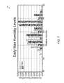
- FIG. 7illustrates a graph 700 of humidity levels for 500 thermostat devices in Florida during the month of August 2012.
- Graph 700is a histogram of daily maximum humidity levels measured within each of the enclosures under observation. The lighter bars represent values measured when the thermostat detected that the home was unoccupied within the past 48 hours. In contrast, the darker bars represent measurements taken when the thermostat determined that the enclosure was not occupied within the last 48 hours. Each of these homes does not have a dedicated dehumidifier accompanying the air conditioner.
- the results of the data displayed in graph 700indicate a number of useful observations.
- the average maximum humidity levelis significantly higher in unoccupied enclosures.
- the average maximum humidity level for occupied enclosuresis 57.0%, while the average maximum humidity level for unoccupied enclosures was 61.1%.
- the distribution of graph 700indicates that most of the daily maximum humidity levels were between approximately 50% and 60% in occupied enclosures.
- a large percentage of the daily maximum humidity levelswere centered between approximately 60% and 70% in the unoccupied enclosures. This indicates a large number of enclosures were subject to maximum humidity levels that far exceeded the EPA's maximum humidity recommendation of between 55% and 60%.
- graph 700indicates that humidity levels may be significantly controlled using the intermittent operation of a cooling function primarily used to control temperature.
- unoccupied enclosurestypically set their temperature setpoint higher while the home is unoccupied. Therefore, the cooling function did not operate as often, and as a result the maximum humidity levels rose dramatically inside the enclosure.
- the temperature setpointwas typically set lower, causing the cooling function to operate more often. This in turn led to a more controlled level of maximum humidity inside the enclosure while the enclosure was occupied.
- cooling functionmay be used to describe any operation of the HVAC system primarily configured to reduce a temperature within an enclosure. Most often, a cooling function will include an air conditioner that uses a fan, a compressor, and cooling coils to force cooled air into the enclosure. Additionally, a cooling function may include the operation of a fan without a compressor and cooling coils. Depending on the particular climate, season, and/or region, the cooling function of an HVAC system may further include other types of cooling systems that would be known to one having skill in the art.
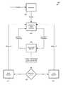
- FIG. 8illustrates a flowchart 800 of a method for reducing a humidity level in an enclosure using a cooling function, according to some embodiments.
- Flowchart 800may be considered a generic algorithm for which the various thresholds, time intervals, and operations may be varied according to an occupancy status of an enclosure.
- flowchart 800may describe what may be presented to a user as an “auto dehumidifier feature.” The user may be given the opportunity to choose to enable or disable the auto dehumidifier feature according to their own comfort level preference and energy-saving concerns. Therefore, in one embodiment, the algorithm may begin in a disabled state 802 until a command is received to enable the auto dehumidifier feature.
- the commandmay be received from a user through a user interface of the thermostat or through a remote interface on a portable computing device such as a laptop, tablet computer, and/or smart phone.
- the commandmay also be received from a central monitoring station that is communicatively coupled through a wireless connection to the thermostat.
- the algorithmmay begin in an enabled state by default instead of being specifically enabled through a command.
- the algorithmmay enter state 804 and begin looking for a high level of humidity.
- the thermostatmay include a humidity sensor that provides humidity sensor measurements to the processing system of the thermostat.
- the processing systemmay compare the humidity sensor measurements to one or more humidity thresholds.
- the humidity thresholdsmay vary according to various modes of operation. In one embodiment, the humidity thresholds may vary according to an occupancy status of the enclosure. Various occupancy statuses of the enclosure and their effects upon the algorithm flowchart 800 are described in greater detail below.
- the algorithmmay transition into state 806 to begin dehumidifying the enclosure using a cooling function, such as an air conditioner.
- a cooling functionsuch as an air conditioner.
- the cooling functionmay already be operating in order to reduce a temperature of the enclosure. In these cases, state 806 may simply continue allowing the cooling function to operate. If the temperature drops below the temperature setpoint that would normally cause the cooling function to stop operating, state 806 may cause the cooling function to continue operating in order to dehumidify the enclosure. In other cases, the temperature of the enclosure may already be at or below the setpoint temperature of the thermostat. In these cases, state 806 may cause the cooling function to operate in order to further dehumidify the enclosure. In other words, the auto dehumidification feature may cause the cooling function to operate at times when it normally would not, and to operate for longer time intervals than it normally would.
- a “set of conditions”may include any parameters used to control the cooling function.
- the set of conditionsmay include information associated with temperature thresholds, humidity thresholds, time intervals, occupancy statuses, user preferences, energy usage, date and time, user profiles, and/or the like that can be used to control when the auto dehumidification features operates the cooling function of the HVAC system.
- the set of conditionsmay be dynamically adjusted using environmental measurements or communications received from a central monitoring facility or a user device.
- the algorithmmay transition out of state 806 when the measured humidity level in the enclosure exceeds a humidity threshold.
- the humidity threshold used to transition out of state 806may be related to the humidity threshold used to transition into state 806 and may also be determined based on an occupancy status of the enclosure and/or user preferences.
- a target humidity levelmay be 55%.
- This target humidity levelmay include a maintenance band, or hysteresis, to prevent rapid transitions between states.
- a maintenance band of 6%may be used. This would yield an upper humidity threshold of 58% to enter into state 806 and a lower humidity threshold of 52% in order to leave state 806 .
- Some embodimentsmay also adjust the humidity threshold based on an occupancy status of the enclosure. For example, it may be determined that a particular enclosure seals out humidity when the enclosure is unoccupied and doors/windows are not being opened/closed on a regular basis. It may be a more efficient use of the cooling function to begin dehumidifying at a higher level of humidity and allow the algorithm a flowchart 800 to operate continuously until a humidity threshold much lower than the high level of humidity is achieved. In contrast, it may be more effective to operate with a smaller maintenance band when the home is occupied in order to maintain a more constant level of humidity for user comfort.
- a target humidity thresholdmay be set to approximately 55% when the enclosure is unoccupied. In other embodiments, the target humidity threshold may be set to approximately 60%. In contrast, when the enclosure is occupied the target humidity threshold they be set significantly above 55%. For example, the target humidity threshold may be set to 65%, 70%, 75%, 80%, and/or the like.
- the set of conditions for exiting state 806may also include temperature considerations. Even though the cooling function is operating primarily to dehumidify the enclosure rather than to lower the temperature, the temperature will still be lowered as the cooling function continues to operate. In order to balance user comfort and energy considerations with the benefits of dehumidification, it may be determined that excessive cooling should be avoided. Therefore, some embodiments may also compare the measured temperature during a dehumidification cycle to a minimum temperature and transition out of state 806 when the minimum temperature threshold is violated.
- the minimum temperaturemay be based on the occupancy status of the enclosure as detected by the thermostat. In some embodiments, the minimum temperature may be a number of degrees below the setpoint temperature. For example, when the enclosure is occupied, user comfort may dictate that the auto dehumidification feature not cool the enclosure more than approximately 3° below the setpoint temperature. When the enclosure is unoccupied and user comfort may not be the primary concern, the auto dehumidification feature may be allowed to cool the enclosure farther below the setpoint temperature. For example, the dehumidification feature may cool the enclosure to approximately 5° below the setpoint temperature. When the enclosure is unoccupied, effective dehumidification may be more of a concern than user comfort. However, assuming that the enclosure will eventually become occupied again, user comfort may also dictate that the enclosure temperature should not be cooled excessively.
- minimum and/or maximum temperaturesmay also be used.
- the usersmay turn off the cooling function or may set the setpoint temperature very high after they leave the house.
- a homeownermay set the thermostat setpoint temperature to 95° and activate the auto dehumidification feature.
- the thermostatmay use a maximum temperature of 90° in order to determine a threshold temperature for deactivating the auto dehumidification algorithm.
- an absolute minimummay be used. For example, a minimum of 75° may be used by the algorithm as a threshold temperature below which the auto dehumidification feature should not cool. For example, if a user were to set the setpoint temperature very close to the minimum temperature, the auto dehumidification algorithm would cool until the minimum temperature was reached rather than the threshold temperature below the setpoint temperature that would otherwise be dictated by the algorithm under normal conditions.
- Some embodimentsmay also include a time interval in the set of conditions for exiting state 806 .
- a time intervalin the set of conditions for exiting state 806 .
- an absolute time intervalmay be used, such that the cooling function will only be operated for a maximum length of time, such as one hour.
- humidity sensor measurementsmay be periodically monitored to determine when a predetermined time interval is exceeded wherein the measured humidity does not substantially change.
- the algorithmmay transition out of state 806 when, for example, 30 minutes have passed without any significant change in the humidity of the enclosure.
- flowchart 800there are two ways to exit state 806 .
- the humidity level in the enclosureis the reason for leaving state 806
- flowchart 800may transition back into state 804 and again watch for the measured humidity to exceed the higher threshold.
- the algorithmmay instead transition into decision block 808 .
- These types of conditionsmay indicate that even though the desired humidity level has not yet been reached, there may be some benefit to stopping the cooling function periodically. These benefits may be related to user comfort, efficiency, and/or energy and cost savings.
- the temperaturewhen operating the cooling function in order to dehumidify the enclosure, the temperature may decrease too far below the setpoint temperature. It may be necessary to allow the enclosure temperature to recover without significantly increasing the humidity. Additionally, when operating the cooling function for an extended period time, it may reach a point where it is no longer efficiently removing humidity from the enclosure. Continuously running the cooling function without removing significant humidity may not be cost effective. Therefore, it may be determined that the efficiency of the auto dehumidification feature may be increased by instituting backoff intervals where the cooling function is allowed to recover such that it may more effectively remove humidity during the next cooling cycle. The rationale and operation of the backup intervals will be described in greater detail below.
- the number of consecutive dehumidification cooling cyclesmay be compared to a threshold number. If the number of dehumidification cooling cycles exceeds the threshold number, a longer backoff interval may be used.
- the longer backoff intervalmay be substantially longer than the shorter backoff interval.
- the longer backoff intervalmay be at least four times as long as the short backoff interval.
- the short backoff intervalmay be approximately 15 minutes in some embodiments, while the long backoff interval may be approximately 1 hour.
- the threshold number of consecutive dehumidification cooling cyclesmay be approximately three cycles.
- the third backoff intervalmay be implemented in order to reset the operation of the auto dehumidification feature, as will be described below.
- the lengths of the backoff intervals and the number of dehumidification cycles between backoff intervalsmay vary for each thermostat type and enclosure.
- the various humidity thresholds, temperature thresholds, backoff interval thresholds, backoff interval lengths, and/or the likemay be dependent upon user preferences as well as an occupancy status of the enclosure. These values may be determined dynamically according to received data from the sensors of the thermostat, and may be processed or assigned from a central processing location that is in wireless communication with the thermostat.
- flowchart 800may be governed by two separate sets of conditions, namely a first set of conditions and a second set of conditions. These two sets of conditions include first and second humidity thresholds, respectively. These two sets of conditions may cause the auto dehumidification feature to operate as an “occupancy status sensitive automated dehumidification feature” that includes an occupied-state automated dehumidification algorithm and an away-state automated dehumidification algorithm. These two algorithms may both follow flowchart 800 . In some cases these two algorithms may only differ in the values of the conditions used to govern transitions between states.
- the occupied-state automated dehumidification algorithmmay operate according to combined comfort-and-humidity criteria. These criteria may dictate values for the set of conditions, and may be characterized in that the cooling function is operated to reduce the humidity in the enclosure according to a first set of conditions that are tailored to balance user comfort with humidity reduction.
- the away-state automated dehumidification algorithmmay be designed to operate according to away-humidity criteria that may dictate values for another set of conditions, and may be tailored to balance humidity reduction with energy and efficiency concerns.
- the currently described methodsmay be used in conjunction with an intelligent, network-connected thermostat having one or more occupancy sensors and being configured and programmed to detect a plurality of occupancy statuses of the enclosure.
- occupancy statusesmay include (i) a “home” or “occupied” status in which it is determined likely that the home is occupied, (ii) an automated away status (or “auto-away” state) in which it is automatically determined based on occupancy sensor readings that the home is likely unoccupied, (iii) a manually invoked away status (or “manual” away) in which an affirmative user entry instructs the thermostat to function at “away” settings regardless of automated occupancy determinations, and (iv) a long-term away status (or “vacation” away state) in which it is determined that the house has likely been unoccupied for an extended time period and therefore is likely to continue to be so unoccupied for the near future.
- the terms occupied or unoccupied/awaymay be used to indicate one or more of the occupancy statuses described above.
- the unoccupied/away statemay correspond to the long-term away or vacation away status, with all other statuses corresponding to the occupied state.
- the unoccupied/away statemay correspond to the auto away status, the manual away status, and the long-term away status, while the occupied state corresponds to the occupied status described above.
- FIG. 9illustrates a flowchart 900 of a method for turning on the long-term away state, according to some embodiments.
- the away-state automated dehumidification algorithmmay be configured to operate with the thermostat in the long-term away status (the “away state”), while the occupied-state automated dehumidification algorithm may be configured to operate in the rest of the occupied statuses (the “occupied state”).
- the algorithmmay default to begin in the occupied state 902 .
- the thermostatmay then transition into an away status, such as the auto away status detected by the one or more occupancy sensors, or the manual away status as specified by a user.
- the algorithmmay then use an internal clock or a date and time system available through a wireless network in order to count a number of days that have passed since the thermostat entered into the away status.
- the thermostatmay, for example, count the number of midnight crossings that have occurred since the thermostat went into one of the away statuses.
- the thermostatmay transition into a long-term away status. This long-term away status may correspond to the away-state automated dehumidification algorithm.
- the algorithmmay then move into the away state 908 , and stay there until the thermostat receives either user inputs or sensor input indicating that a transition should be made back to the occupied state 902 .
- the algorithm of flowchart 900uses the long-term away status rather than the auto-away status or the manual-away status to transition to the away-state automated dehumidification algorithm.
- other embodimentsmay simply transition to the away-state automated dehumidification algorithm when any of the away statuses are indicated by the thermostat.
- using the long-term away statusmay be more effective at balancing user comfort with energy/efficiency concerns.
- Many thermostatsmay enter the auto away state after the enclosure has been unoccupied for a few hours.
- the excess cooling that may occur using the away-state automated dehumidification algorithmmay be uncomfortable for users who intend to return to the enclosure after a few hours.
- some air conditioning unitsmay have an optimal time interval during which humidity may be removed.
- the air conditionershould be allowed to operate for at least a minimum time interval in order to dehumidify the enclosure.
- Some air conditioner unitsmay require a warming-up period before they begin removing moisture from the atmosphere.
- Other air-conditioning unitsmay simply be most efficient during the first portion of an air-conditioning cycle. In either case, it may be most efficient to allow the cooling function to operate for at least the minimum amount of time.
- FIG. 10illustrates a graph 1000 of multiple dehumidification cycles using backoff intervals, according to some embodiments.
- humidity level H 1 and humidity level H 2may correspond to upper and lower humidity maintenance band thresholds that are determined by the occupancy status of the enclosure.
- the cooling functionmay be activated at time t 1 .
- Curve 1002illustrates how this particular air conditioner is most effective at removing humidity from the air during the first portion of the time interval. However, as time progresses the cooling function becomes less efficient at removing humidity, and curve 1002 begins to flatten.
- the auto dehumidification algorithmmay then turn off the cooling function.
- the cooling functionmay have instead been deactivated because the temperature descended below the setpoint temperature by more than the threshold value, or because the maximum time interval was reached during which the flat portion of curve 1002 indicated that the humidity of an enclosure was not being significantly reduced.
- Curve 1004may occur during the backoff interval. Note that curve 1004 indicates that the humidity may slightly rise in the enclosure after the cooling function is deactivated. After the backoff interval expires at time t 3 , the cooling function may again operate to remove humidity from the atmosphere. Curve 1006 is of a similar shape of curve 1002 ; however, it should be noted that the total humidity reduction of curve 1006 is less than that of curve 1002 . Again, at time t 4 , the cooling function may be deactivated due to either efficiency or temperature conditions, and a second backoff interval may begin characterized by curve 1008 . At time t 5 , a third dehumidification cycle may begin as characterized by curve 1010 . Again note that the total humidity reduction of curve 1010 is less than that of both curve 1006 and curve 1002 .
- Graph 1000illustrates the fact that there is a time at which a single dehumidification cycle using the cooling function may become inefficient.
- Graph 1000also illustrates the fact that repeated dehumidification cycles may also gradually become inefficient.
- Curve 1010is significantly flatter than curve 1002 . Therefore, repeatedly running dehumidification cycles may eventually limit the effectiveness of the cooling function at reducing enclosure humidity.
- One solution implemented by some embodimentsis to simply increase the time of the backoff intervals between each cycle. However, as illustrated by curve 1004 and curve 1008 , the humidity of the enclosure may begin to increase during the backoff intervals.
- some embodimentsmay use a determined number of short backoff intervals followed by a longer backoff interval.
- the shorter backoff intervalsmay effectively reduce the humidity over a shorter period of time, while the longer backoff interval may allow the components of the cooling system to reset, condense, and return to a normal temperature. It has been determined that after allowing the air conditioner to “reset” using a longer backoff interval, the dehumidification cycles may restart using shorter backoff intervals at near the original efficiency.
- FIG. 11illustrates a graph 1100 of a determined number of dehumidification cycles followed by a longer backoff interval, according to some embodiments.
- the portion of the humidity curve prior to time t 6may be similar to the curve illustrated by graph 1000 .
- the thermostatmay determine that the threshold number of dehumidification cycles has been reached, and instead of instituting a shorter backoff interval, the longer backoff interval may be used instead.
- curve 1102illustrates that the humidity may rise more than during the shorter backoff intervals.
- the longer backoff intervalmay expire, and the dehumidification cycles may be restarted.
- the humidity curve 1104 of the first new dehumidification cycleis similar in shape to the original curve 1002 of the first original dehumidification cycle.
- the longer backoff intervalmay be effective at restoring near the original efficiency of the cooling function at removing humidity from the enclosure.
- FIG. 12Aillustrates a user interface of a thermostat 1200 a for enabling the auto dehumidification feature, according to some embodiments.
- Usersmay be allowed to turn the auto dehumidifier feature on or off depending upon their concerns for cost savings, energy efficiency, mold prevention, and/or the like.
- the user interfacemay provide a message describing the benefits of using the auto dehumidification feature, such as mold prevention. Additionally, the user interface may provide an indication that leaving the auto dehumidification feature off may be more efficient. For example, a leaf symbol 1202 may be displayed next to the “off” setting for the auto dehumidification feature in order to indicate that the disabling the feature may be more energy efficient.
- FIG. 12Billustrates a user interface of a thermostat 1200 b providing additional information regarding the auto dehumidification feature, according to some embodiments.
- additional informationmay be provided describing the benefits and risks associated with the auto dehumidification feature.
- the indicationmay explain that the cooling function of the thermostat may be used as a dehumidifier.
- the indicationmay explain that the auto dehumidification feature may cause the cooling function to run when it otherwise would not run, and that this may have an effect on the efficiency of the HVAC system as well as the expense associated with operating the HVAC system.
- the user interfaces described abovemay be presented to a user automatically when certain conditions are detected by the thermostat.
- the thermostatmay be equipped with a wire insertion sensing unit configured to detect when a dehumidifier is properly connected to the thermostat.
- the wire insertion sensing unitmay use mechanical insertion sensors to physically detect when a wire is connected from an HVAC system dehumidifier to the thermostat.
- the wire insertion sensing unitmay also use electronic tests in order to determine that a dehumidifier is properly connected.
- the user interfaces described abovemay be presented to the user. If a dehumidifier is detected, then the user interfaces described above need not be presented automatically. However, users may be given the option to deactivate the dehumidifier and activate the auto dehumidification feature at their discretion through a menu interface of the thermostat.
- thermostatmay be adjusted when the auto dehumidifier feature is enabled. For example, when the user switches the auto dehumidification feature to the “on” state, an “Airwave” feature may be automatically deactivated.
- the Airwave featuremay use condensation from the air conditioner coils to continue cooling the enclosure after the air conditioner compressor has been deactivated.
- the Airwave featuremay also dramatically increase the humidity in the enclosure. Therefore, enabling the auto dehumidification feature may automatically deactivate the Airwave feature of the thermostat.
- the thermostatmay also determine whether the thermostat is in a heat mode rather than a cooling mode. The auto dehumidification feature can be automatically deactivated while the thermostat is in the heating mode and automatically reactivated when the thermostat is set to the cooling mode.
- FIG. 13illustrates a user interface 1300 of a user device for activating the auto dehumidification feature, according to some embodiments.
- This user interfacemay be displayed on a smart phone, a tablet computer, a laptop computer, a PDA, a portable music player, a desktop computer, and/or the like.
- the user devicemay communicate through the Internet, a local area network, a wide-area network, a private network, or using a dedicated wireless connection with the thermostat.
- the user interfacemay provide similar indications as described in relation to FIG. 12A and FIG. 12B that described the costs and benefits associated with the auto dehumidifier feature.
- the user interface 1300may also provide indications that easily allow users to choose the most energy-efficient setting, such as the “leaf” icon.
- User interface 1300may be used to activate or deactivate the auto dehumidification feature while away from the enclosure. This may be particularly beneficial to owners of vacation homes. For example, vacation homes in humid areas such as Florida may experience seasonal heat and/or humidity. Owners may be away from vacation homes for extended periods of time. An owner may decide to leave the auto dehumidification feature off during the winter and activate the auto dehumidification feature during the summer without needing to physically visit the vacation home.
- FIG. 14illustrates a user interface 1400 of a user device for assessing the efficiency of an auto dehumidification feature, according to some embodiments.
- User interface 1400may display various indications that describe how efficiently an HVAC system was used during an extended time interval, such as during one week, during one month, or during a particular season.
- User interface 1400may also include an indication that the auto dehumidification feature caused the energy usage in a particular time interval to be above what would normally be expected.
- User interface 1400may be beneficial to users to explain outlying energy usage and help users associate a cost that can be balanced with a benefit provided by the auto dehumidifier can feature.
- a similar interfacemay be displayed on the thermostat as well as the user device.
- the thermostatmay display an indication describing why the cooling function is currently operating. This may allow users to distinguish between operating the cooling function in order to lower the ambient temperature of the enclosure and operating the cooling function in order to reduce the humidity of the enclosure.
- the indicationmay also describe an occupancy status of the enclosure as determined by the thermostat.
- FIG. 15Aillustrates a user interface of a thermostat 1500 a indicating that the cooling function is operating as part of the auto dehumidification feature.
- a current temperaturemay be displayed without showing time-to-temperature ticks along the dial of the interface.
- a current humiditymay be displayed instead of a current temperature.
- FIG. 15Billustrates a user interface of a thermostat 1500 b indicating that the cooling function may be operating as part of the auto dehumidification feature while the thermostat is in the away state.
- FIG. 15Cillustrates a user interface of a thermostat 1500 c indicating that the cooling function may be operating as part of the auto dehumidification feature while the thermostat is in the auto-away state.
- 15Dillustrates a user interface of a thermostat 1500 d indicating that the cooling function may be operating as a part of the auto dehumidification feature while the thermostat is in the long-term away state.
- Each of these indicationsmay be changed by manually interacting with the thermostat by way of the user interface, or by providing commands to the thermostat from a user device or from a central monitoring station.
- one skilled in the artmay adapt the present teachings to an equivalent but converse case of “do-not-heat-to-too-dry.”
- operating a heatermay reduce the humidity of an enclosure, and depending on the particular context, air that is too dry may be undesirable for one or more reasons (for example, causing dry skin, damage to wood furniture or instruments, or endangering certain pet or plant life).
- the algorithms described hereinmay be applied in a converse context such that the heating function is limited in order to reduce the dryness that can result. For example, when the home is occupied, the heating function may perform as normal until the humidity drops to a specified threshold humidity level.
- the heating functionmay be limited in order to avoid too much of a reduction in humidity, but not limited so much as to allow pipes to freeze or to cause the enclosure to be too cold when the occupants return. Therefore, reference to the details of the preferred embodiments is not intended to limit their scope.
Landscapes
- Engineering & Computer Science (AREA)
- Physics & Mathematics (AREA)
- General Physics & Mathematics (AREA)
- Automation & Control Theory (AREA)
- Air Conditioning Control Device (AREA)
- Remote Sensing (AREA)
Abstract
Description
Claims (18)
Priority Applications (4)
| Application Number | Priority Date | Filing Date | Title |
|---|---|---|---|
| US13/871,746US9696735B2 (en) | 2013-04-26 | 2013-04-26 | Context adaptive cool-to-dry feature for HVAC controller |
| PCT/US2014/035019WO2014176271A1 (en) | 2013-04-26 | 2014-04-22 | Context adaptive cool-to-dry feature for hvac controller |
| CA2910058ACA2910058C (en) | 2013-04-26 | 2014-04-22 | Context adaptive cool-to-dry feature for hvac controller |
| DE212014000109.9UDE212014000109U1 (en) | 2013-04-26 | 2014-04-22 | Context-adaptive cooling-through-drying function for HVAC control |
Applications Claiming Priority (1)
| Application Number | Priority Date | Filing Date | Title |
|---|---|---|---|
| US13/871,746US9696735B2 (en) | 2013-04-26 | 2013-04-26 | Context adaptive cool-to-dry feature for HVAC controller |
Publications (2)
| Publication Number | Publication Date |
|---|---|
| US20140319231A1 US20140319231A1 (en) | 2014-10-30 |
| US9696735B2true US9696735B2 (en) | 2017-07-04 |
Family
ID=51788430
Family Applications (1)
| Application Number | Title | Priority Date | Filing Date |
|---|---|---|---|
| US13/871,746Active2035-11-14US9696735B2 (en) | 2013-04-26 | 2013-04-26 | Context adaptive cool-to-dry feature for HVAC controller |
Country Status (4)
| Country | Link |
|---|---|
| US (1) | US9696735B2 (en) |
| CA (1) | CA2910058C (en) |
| DE (1) | DE212014000109U1 (en) |
| WO (1) | WO2014176271A1 (en) |
Cited By (14)
| Publication number | Priority date | Publication date | Assignee | Title |
|---|---|---|---|---|
| US20180231946A1 (en)* | 2015-08-05 | 2018-08-16 | Tetrascience, Inc. | Methods, Systems, and Devices for Monitoring and Controlling Tools |
| US10560894B2 (en) | 2015-01-13 | 2020-02-11 | Trane International Inc. | Mesh routing of sleepy sensor data |
| US10760803B2 (en) | 2017-11-21 | 2020-09-01 | Emerson Climate Technologies, Inc. | Humidifier control systems and methods |
| US20210373115A1 (en)* | 2014-08-06 | 2021-12-02 | Yogendra C. Shah | Occupancy-based Service Delivery Systems and Methods |
| US11226128B2 (en) | 2018-04-20 | 2022-01-18 | Emerson Climate Technologies, Inc. | Indoor air quality and occupant monitoring systems and methods |
| US11371726B2 (en) | 2018-04-20 | 2022-06-28 | Emerson Climate Technologies, Inc. | Particulate-matter-size-based fan control system |
| US11421901B2 (en) | 2018-04-20 | 2022-08-23 | Emerson Climate Technologies, Inc. | Coordinated control of standalone and building indoor air quality devices and systems |
| US11486593B2 (en) | 2018-04-20 | 2022-11-01 | Emerson Climate Technologies, Inc. | Systems and methods with variable mitigation thresholds |
| US11609004B2 (en) | 2018-04-20 | 2023-03-21 | Emerson Climate Technologies, Inc. | Systems and methods with variable mitigation thresholds |
| US11994313B2 (en) | 2018-04-20 | 2024-05-28 | Copeland Lp | Indoor air quality sensor calibration systems and methods |
| US12018852B2 (en) | 2018-04-20 | 2024-06-25 | Copeland Comfort Control Lp | HVAC filter usage analysis system |
| US12078373B2 (en) | 2018-04-20 | 2024-09-03 | Copeland Lp | Systems and methods for adjusting mitigation thresholds |
| US12259148B2 (en) | 2018-04-20 | 2025-03-25 | Copeland Lp | Computerized HVAC filter evaluation system |
| US12311308B2 (en) | 2018-04-20 | 2025-05-27 | Copeland Lp | Particulate-matter-size-based fan control system |
Families Citing this family (31)
| Publication number | Priority date | Publication date | Assignee | Title |
|---|---|---|---|---|
| US9696735B2 (en) | 2013-04-26 | 2017-07-04 | Google Inc. | Context adaptive cool-to-dry feature for HVAC controller |
| US20150025659A1 (en)* | 2013-07-17 | 2015-01-22 | Google Inc. | Home Automation Network |
| US9697700B2 (en)* | 2013-11-20 | 2017-07-04 | Honeywell International Inc. | Ambient condition detector with processing of incoming audible commands followed by speech recognition |
| USD798888S1 (en)* | 2013-12-23 | 2017-10-03 | Canonical Limited | Touchscreen device with graphical user interface |
| US10430526B2 (en)* | 2014-02-18 | 2019-10-01 | Safaira, Inc. | Systems and methods for displaying impact analysis data while designing an architectural structure |
| DE102014204321A1 (en)* | 2014-03-10 | 2015-09-10 | Ford Global Technologies, Llc | Switch for selecting and adjusting seat-related functions of motor vehicle seats |
| USD761859S1 (en)* | 2014-06-20 | 2016-07-19 | Samsung Electronics Co., Ltd. | Display screen or portion thereof with icon |
| US10677484B2 (en) | 2015-05-04 | 2020-06-09 | Johnson Controls Technology Company | User control device and multi-function home control system |
| AU2016257459B2 (en) | 2015-05-04 | 2019-04-04 | Johnson Controls Technology Company | Multi-function home control system with control system hub and remote sensors |
| US11216020B2 (en) | 2015-05-04 | 2022-01-04 | Johnson Controls Tyco IP Holdings LLP | Mountable touch thermostat using transparent screen technology |
| US10760809B2 (en) | 2015-09-11 | 2020-09-01 | Johnson Controls Technology Company | Thermostat with mode settings for multiple zones |
| US10410300B2 (en) | 2015-09-11 | 2019-09-10 | Johnson Controls Technology Company | Thermostat with occupancy detection based on social media event data |
| US10345781B2 (en) | 2015-10-28 | 2019-07-09 | Johnson Controls Technology Company | Multi-function thermostat with health monitoring features |
| US11277893B2 (en) | 2015-10-28 | 2022-03-15 | Johnson Controls Technology Company | Thermostat with area light system and occupancy sensor |
| US10546472B2 (en) | 2015-10-28 | 2020-01-28 | Johnson Controls Technology Company | Thermostat with direction handoff features |
| US10655881B2 (en) | 2015-10-28 | 2020-05-19 | Johnson Controls Technology Company | Thermostat with halo light system and emergency directions |
| US10318266B2 (en) | 2015-11-25 | 2019-06-11 | Johnson Controls Technology Company | Modular multi-function thermostat |
| US10118696B1 (en) | 2016-03-31 | 2018-11-06 | Steven M. Hoffberg | Steerable rotating projectile |
| US10000912B2 (en)* | 2016-06-15 | 2018-06-19 | Honeywell International Inc. | Freeze prediction system |
| US10941951B2 (en) | 2016-07-27 | 2021-03-09 | Johnson Controls Technology Company | Systems and methods for temperature and humidity control |
| US10458669B2 (en) | 2017-03-29 | 2019-10-29 | Johnson Controls Technology Company | Thermostat with interactive installation features |
| WO2018191510A1 (en) | 2017-04-14 | 2018-10-18 | Johnson Controls Technology Company | Multi-function thermostat with air quality display |
| US11162698B2 (en) | 2017-04-14 | 2021-11-02 | Johnson Controls Tyco IP Holdings LLP | Thermostat with exhaust fan control for air quality and humidity control |
| US11131474B2 (en) | 2018-03-09 | 2021-09-28 | Johnson Controls Tyco IP Holdings LLP | Thermostat with user interface features |
| US11712637B1 (en) | 2018-03-23 | 2023-08-01 | Steven M. Hoffberg | Steerable disk or ball |
| KR102026020B1 (en)* | 2018-04-10 | 2019-11-26 | 엘지전자 주식회사 | Air-conditioner based on parameter learning using artificial intelligence, cloud server, and method of operating and controlling thereof |
| US11107390B2 (en) | 2018-12-21 | 2021-08-31 | Johnson Controls Technology Company | Display device with halo |
| US11193689B2 (en)* | 2019-06-14 | 2021-12-07 | Johnson Controls Tyco IP Holdings LLP | Building HVAC system with predictive temperature and humidity control |
| DE102019216804A1 (en)* | 2019-10-30 | 2021-05-06 | Robert Bosch Gmbh | Output device, device with the output device and method for an environment-specific output of information by means of the output device |
| US11892187B2 (en)* | 2020-03-26 | 2024-02-06 | Generac Power Systems, Inc. | Thermostat device with improved energy optimization |
| USD983818S1 (en)* | 2023-01-30 | 2023-04-18 | Hangzhou Ruisheng Software Co., Ltd. | Display screen with animated graphical user interface |
Citations (120)
| Publication number | Priority date | Publication date | Assignee | Title |
|---|---|---|---|---|
| US3991357A (en) | 1974-04-30 | 1976-11-09 | The Stolle Corporation | Storage battery monitoring and recharging control system with automatic control of prime mover driving charging generator |
| US4183290A (en) | 1977-04-29 | 1980-01-15 | Siegenia-Frank Kg. | Air vent |
| US4223831A (en) | 1979-02-21 | 1980-09-23 | Szarka Jay R | Sound activated temperature control system |
| US4335847A (en) | 1980-05-27 | 1982-06-22 | Levine Michael R | Electronic thermostat with repetitive operation cycle |
| US4408711A (en) | 1980-11-14 | 1983-10-11 | Levine Michael R | Thermostat with adaptive operating cycle |
| JPS59106311A (en) | 1982-12-09 | 1984-06-20 | Nippon Denso Co Ltd | Auto air conditioner control device |
| EP0196069A2 (en) | 1985-03-29 | 1986-10-01 | Honeywell Inc. | Clock operated thermostat |
| US4615380A (en) | 1985-06-17 | 1986-10-07 | Honeywell Inc. | Adaptive clock thermostat means for controlling over and undershoot |
| US4674027A (en) | 1985-06-19 | 1987-06-16 | Honeywell Inc. | Thermostat means adaptively controlling the amount of overshoot or undershoot of space temperature |
| US4685614A (en) | 1980-05-27 | 1987-08-11 | Honeywell, Inc. | Analog to digital conversion employing the system clock of a microprocessor, the clock frequency varying with analog input |
| US4751961A (en) | 1986-02-18 | 1988-06-21 | Honeywell Inc. | Electronic programmable thermostat |
| JPH01252850A (en) | 1987-12-24 | 1989-10-09 | Mitsubishi Electric Corp | Display device for airconditioner |
| US4897798A (en) | 1986-12-08 | 1990-01-30 | American Telephone And Telegraph Company | Adaptive environment control system |
| US4971136A (en) | 1989-11-28 | 1990-11-20 | Electric Power Research Institute | Dual fuel heat pump controller |
| US5088645A (en) | 1991-06-24 | 1992-02-18 | Ian Bell | Self-programmable temperature control system for a heating and cooling system |
| US5211332A (en) | 1991-09-30 | 1993-05-18 | Honeywell Inc. | Thermostat control |
| US5240178A (en) | 1991-09-05 | 1993-08-31 | Dewolf Thomas L | Active anticipatory control |
| US5244146A (en) | 1992-05-08 | 1993-09-14 | Homebrain, Inc. | Energy-conserving thermostat and method |
| US5395042A (en) | 1994-02-17 | 1995-03-07 | Smart Systems International | Apparatus and method for automatic climate control |
| US5476221A (en) | 1994-01-28 | 1995-12-19 | Seymour; Richard L. | Easy-to-install thermostatic control system based on room occupancy |
| US5499196A (en) | 1993-08-18 | 1996-03-12 | P.C. Sentry, Inc. | Sensor interface for computer-based notification system |
| US5544809A (en) | 1993-12-28 | 1996-08-13 | Senercomm, Inc. | Hvac control system and method |
| US5555927A (en) | 1995-06-07 | 1996-09-17 | Honeywell Inc. | Thermostat system having an optimized temperature recovery ramp rate |
| US5611484A (en) | 1993-12-17 | 1997-03-18 | Honeywell Inc. | Thermostat with selectable temperature sensor inputs |
| US5808294A (en) | 1997-01-14 | 1998-09-15 | Kenco Automatic Feeders | Electronic controller for scheduling device activation by sensing daylight |
| CA2202008A1 (en) | 1997-04-07 | 1998-10-07 | Hugues Demilleville | Energy management system |
| US5902183A (en) | 1996-11-15 | 1999-05-11 | D'souza; Melanius | Process and apparatus for energy conservation in buildings using a computer controlled ventilation system |
| US5909378A (en) | 1997-04-09 | 1999-06-01 | De Milleville; Hugues | Control apparatus and method for maximizing energy saving in operation of HVAC equipment and the like |
| US5918474A (en) | 1996-07-30 | 1999-07-06 | Whirlpool Corporation | Fan motor on/off control system for a refrigeration appliance |
| US5977964A (en) | 1996-06-06 | 1999-11-02 | Intel Corporation | Method and apparatus for automatically configuring a system based on a user's monitored system interaction and preferred system access times |
| US6062482A (en) | 1997-09-19 | 2000-05-16 | Pentech Energy Solutions, Inc. | Method and apparatus for energy recovery in an environmental control system |
| US6066843A (en) | 1998-04-06 | 2000-05-23 | Lightstat, Inc. | Light discriminator for a thermostat |
| US6070110A (en)* | 1997-06-23 | 2000-05-30 | Carrier Corporation | Humidity control thermostat and method for an air conditioning system |
| US6072784A (en) | 1997-07-25 | 2000-06-06 | At&T Corp. | CDMA mobile station wireless transmission power management with adaptive scheduling priorities based on battery power level |
| US6095427A (en) | 1999-04-22 | 2000-08-01 | Thermo King Corporation | Temperature control system and method for efficiently obtaining and maintaining the temperature in a conditioned space |
| US6098893A (en) | 1998-10-22 | 2000-08-08 | Honeywell Inc. | Comfort control system incorporating weather forecast data and a method for operating such a system |
| US6216956B1 (en) | 1997-10-29 | 2001-04-17 | Tocom, Inc. | Environmental condition control and energy management system and method |
| US6349883B1 (en) | 1999-02-09 | 2002-02-26 | Energy Rest, Inc. | Energy-saving occupancy-controlled heating ventilating and air-conditioning systems for timing and cycling energy within different rooms of buildings having central power units |
| US6356204B1 (en) | 1997-08-19 | 2002-03-12 | Tectonics Research Group, Inc. | Method and apparatus for detecting impending earthquakes |
| US6370894B1 (en) | 2001-03-08 | 2002-04-16 | Carrier Corporation | Method and apparatus for using single-stage thermostat to control two-stage cooling system |
| US6415205B1 (en) | 1997-02-04 | 2002-07-02 | Mytech Corporation | Occupancy sensor and method of operating same |
| US6478233B1 (en) | 2000-12-29 | 2002-11-12 | Honeywell International Inc. | Thermal comfort controller having an integral energy savings estimator |
| US20030181158A1 (en)* | 2002-01-31 | 2003-09-25 | Edwards Systems Technology, Inc. | Economizer control |
| US6645066B2 (en) | 2001-11-19 | 2003-11-11 | Koninklijke Philips Electronics N.V. | Space-conditioning control employing image-based detection of occupancy and use |
| US6769482B2 (en) | 2001-05-10 | 2004-08-03 | Ranco Incorporated Of Delaware | System and method for switching-over between heating and cooling modes |
| US20040249479A1 (en) | 2003-04-07 | 2004-12-09 | Shorrock John E. | Systems and methods for monitoring room conditions to improve occupant performance |
| US6843068B1 (en) | 2003-07-25 | 2005-01-18 | Honeywell International Inc. | Method and apparatus for adjusting the temperature set point based on humidity level for increased comfort |
| US20050090915A1 (en) | 2002-10-22 | 2005-04-28 | Smart Systems Technologies, Inc. | Programmable and expandable building automation and control system |
| US20050128067A1 (en) | 2003-12-11 | 2005-06-16 | Honeywell International, Inc. | Automatic sensitivity adjustment on motion detectors in security system |
| US20050150968A1 (en) | 2004-01-09 | 2005-07-14 | Shearer Jon D. | Low noise solid-state thermostat with microprocessor controlled fault detection and reporting, and programmable set points |
| US20050189429A1 (en) | 2004-02-28 | 2005-09-01 | Breeden Robert L. | Thermostat and method for adaptively providing a changeover between heat and cool |
| US20050192915A1 (en) | 2004-02-27 | 2005-09-01 | Osman Ahmed | System and method for predicting building thermal loads |
| US20050280421A1 (en) | 2003-08-27 | 2005-12-22 | Nec Mobiling, Ltd. | Earthquarke prediction method and system thereof |
| US6990821B2 (en) | 2001-05-03 | 2006-01-31 | Emerson Retail Services Inc. | Model-based alarming |
| US7024336B2 (en) | 2004-05-13 | 2006-04-04 | Johnson Controls Technology Company | Method of and apparatus for evaluating the performance of a control system |
| US7083109B2 (en) | 2003-08-18 | 2006-08-01 | Honeywell International Inc. | Thermostat having modulated and non-modulated provisions |
| US20060186214A1 (en) | 2005-01-19 | 2006-08-24 | Tim Simon, Inc. | Thermostat operation method and apparatus |
| US20060196953A1 (en) | 2005-01-19 | 2006-09-07 | Tim Simon, Inc. | Multiple thermostat installation |
| US20060260334A1 (en)* | 2005-05-17 | 2006-11-23 | Carey Steven L | Thermostat and method for operating in either a normal or dehumidification mode |
| US7149727B1 (en) | 2000-11-01 | 2006-12-12 | Avista Advantage, Inc. | Computerized system and method for providing cost savings for consumers |
| US7149729B2 (en) | 2003-03-27 | 2006-12-12 | Microsoft Corporation | System and method for filtering and organizing items based on common elements |
| US20070045431A1 (en) | 2005-08-31 | 2007-03-01 | Ranco Incorporated Of Delaware | Occupancy-based zoning climate control system and method |
| US7188482B2 (en) | 2004-08-27 | 2007-03-13 | Carrier Corporation | Fault diagnostics and prognostics based on distance fault classifiers |
| US20070115902A1 (en) | 2004-11-18 | 2007-05-24 | Charles Shamoon | Ubiquitous connectivity and control system for remote locations |
| US7222800B2 (en) | 2003-08-18 | 2007-05-29 | Honeywell International Inc. | Controller customization management system |
| US20070205297A1 (en) | 2006-03-03 | 2007-09-06 | Finkam Joseph E | Methods and apparatuses for controlling air to a building |
| US20080015742A1 (en) | 2006-07-11 | 2008-01-17 | Regen Energy Inc. | Method and apparatus for managing an energy consuming load |
| US7379791B2 (en) | 2004-08-03 | 2008-05-27 | Uscl Corporation | Integrated metrology systems and information and control apparatus for interaction with integrated metrology systems |
| USRE40437E1 (en) | 2004-11-23 | 2008-07-15 | Howard Rosen | Thermostat system with remote data averaging |
| US20080183335A1 (en) | 2001-08-22 | 2008-07-31 | Poth Robert J | Usage monitoring HVAC control method |
| US20080191045A1 (en) | 2007-02-09 | 2008-08-14 | Harter Robert J | Self-programmable thermostat |
| US20080273754A1 (en) | 2007-05-04 | 2008-11-06 | Leviton Manufacturing Co., Inc. | Apparatus and method for defining an area of interest for image sensing |
| US20080317292A1 (en) | 2007-06-25 | 2008-12-25 | Microsoft Corporation | Automatic configuration of devices based on biometric data |
| US7469550B2 (en) | 2004-01-08 | 2008-12-30 | Robertshaw Controls Company | System and method for controlling appliances and thermostat for use therewith |
| US20090158758A1 (en)* | 2005-12-01 | 2009-06-25 | Matsushita Electric Industrial Co., Ltd. | Indoor air conditioner and operation control method thereof |
| US20090171862A1 (en) | 2007-12-28 | 2009-07-02 | Johnson Controls Technology Company | Energy control system |
| US20090254225A1 (en) | 2004-04-16 | 2009-10-08 | Boucher Rodney M | Enterprise Energy Automation |
| US20090259713A1 (en) | 2001-02-24 | 2009-10-15 | International Business Machines Corporation | Novel massively parallel supercomputer |
| US20090297901A1 (en) | 2005-12-20 | 2009-12-03 | Gm Global Technology Operations, Inc. | Power system for a hybrid fuel cell vehicle that employs a floating base load strategy |
| US20090327354A1 (en) | 2008-06-26 | 2009-12-31 | Microsoft Corporation | Notification and synchronization of updated data |
| US7644869B2 (en) | 2005-12-28 | 2010-01-12 | Honeywell International Inc. | Auxiliary stage control of multistage thermostats |
| US20100019051A1 (en) | 2008-07-22 | 2010-01-28 | Howard Rosen | Override Of Nonoccupancy Status In a Thermostat Device Based Upon Analysis Of Recent Patterns Of Occupancy |
| US20100025483A1 (en) | 2008-07-31 | 2010-02-04 | Michael Hoeynck | Sensor-Based Occupancy and Behavior Prediction Method for Intelligently Controlling Energy Consumption Within a Building |
| US20100050004A1 (en) | 2008-08-20 | 2010-02-25 | International Business Machines Corporation | Introducing selective energy efficiency in a virtual environment |
| US20100070086A1 (en) | 2008-09-15 | 2010-03-18 | Johnson Controls Technology Company | Indoor air quality controllers and user interfaces |
| US20100070234A1 (en) | 2007-09-17 | 2010-03-18 | John Douglas Steinberg | System and method for evaluating changes in the efficiency of an hvac system |
| US20100070084A1 (en) | 2008-09-16 | 2010-03-18 | John Douglas Steinberg | System and method for calculating the thermal mass of a building |
| US20100084482A1 (en) | 2007-03-23 | 2010-04-08 | Pro1 Iaq | Thermostat |
| US7702424B2 (en) | 2003-08-20 | 2010-04-20 | Cannon Technologies, Inc. | Utility load control management communications protocol |
| US20100167783A1 (en) | 2008-12-31 | 2010-07-01 | Motorola, Inc. | Portable Electronic Device Having Directional Proximity Sensors Based on Device Orientation |
| US20100179704A1 (en) | 2009-01-14 | 2010-07-15 | Integral Analytics, Inc. | Optimization of microgrid energy use and distribution |
| US20100211224A1 (en) | 2008-12-19 | 2010-08-19 | EnaGea LLC | Heating and cooling control methods and systems |
| US20100262299A1 (en) | 2008-07-07 | 2010-10-14 | Leo Cheung | System and method for using ramped setpoint temperature variation with networked thermostats to improve efficiency |
| US20100262298A1 (en) | 2009-03-27 | 2010-10-14 | Siemens Energy & Automation, Inc. | System and Method for Climate Control Set-Point Optimization Based On Individual Comfort |
| US20100280667A1 (en) | 2008-07-14 | 2010-11-04 | John Douglas Steinberg | System and method for using a networked electronic device as an occupancy sensor for an energy management system |
| US20100289643A1 (en) | 2009-05-18 | 2010-11-18 | Alarm.Com | Remote device control and energy monitoring |
| US20100308119A1 (en) | 2009-05-12 | 2010-12-09 | Ecofactor, Inc. | System, method and apparatus for identifying manual inputs to and adaptive programming of a thermostat |
| US7849698B2 (en) | 2005-03-02 | 2010-12-14 | York International Corporation | Method and apparatus to sense and establish operation mode for an HVAC control |
| US20100318227A1 (en) | 2009-05-08 | 2010-12-16 | Ecofactor, Inc. | System, method and apparatus for just-in-time conditioning using a thermostat |
| US7854389B2 (en) | 2005-08-30 | 2010-12-21 | Siemens Industry Inc. | Application of microsystems for comfort control |
| US20110046806A1 (en) | 2009-08-18 | 2011-02-24 | Control4 Corporation | Systems and methods for estimating the effects of a request to change power usage |
| US20110046792A1 (en) | 2009-08-21 | 2011-02-24 | Imes Kevin R | Energy Management System And Method |
| US20110046805A1 (en) | 2009-08-18 | 2011-02-24 | Honeywell International Inc. | Context-aware smart home energy manager |
| US20110077758A1 (en) | 2007-05-24 | 2011-03-31 | Alexander Bach Tran | Smart air ventilation system |
| US20110151837A1 (en) | 2009-12-23 | 2011-06-23 | Winbush Iii Amos | Mobile communication device user content synchronization with central web-based records and information sharing system |
| US20110160913A1 (en) | 2009-12-31 | 2011-06-30 | Schneider Electric USA, Inc. | Methods and apparatuses for displaying energy savings from an hvac system |
| US20110185895A1 (en) | 2010-02-03 | 2011-08-04 | Paul Freen | Filter apparatus and method of monitoring filter apparatus |
| US8037022B2 (en) | 2007-06-05 | 2011-10-11 | Samsung Electroncis Co., Ltd. | Synchronizing content between content directory service and control point |
| US20110307112A1 (en) | 2010-06-15 | 2011-12-15 | Redwood Systems, Inc. | Goal-based control of lighting |
| US8090477B1 (en) | 2010-08-20 | 2012-01-03 | Ecofactor, Inc. | System and method for optimizing use of plug-in air conditioners and portable heaters |
| US8091375B2 (en) | 2006-05-10 | 2012-01-10 | Trane International Inc. | Humidity control for air conditioning system |
| US20120017611A1 (en) | 2010-07-20 | 2012-01-26 | Coffel James A | Load management aware fan control |
| US20120085831A1 (en) | 2010-10-07 | 2012-04-12 | Energy Eye, Inc. | Systems and methods for controlling the temperature of a room based on occupancy |
| US20120130679A1 (en)* | 2010-11-19 | 2012-05-24 | Nest Labs, Inc. | Thermostat facilitating user-friendly installation thereof |
| US20120186774A1 (en)* | 2010-11-19 | 2012-07-26 | Nest Labs, Inc. | Control unit with automatic setback capability |
| US20120252430A1 (en) | 2009-08-21 | 2012-10-04 | Imes Kevin R | Establishing proximity detection using 802.11 based networks |
| US20130103204A1 (en) | 2011-10-21 | 2013-04-25 | Nest Labs, Inc. | Prospective determination of processor wake-up conditions in energy buffered hvac control unit |
| US20130098596A1 (en) | 2011-10-21 | 2013-04-25 | Nest Labs, Inc. | Smart-Home Device That Self-Qualifies For Away-State Functionality |
| US20140230475A1 (en)* | 2011-09-29 | 2014-08-21 | Daikin Industries, Ltd. | Humidity control apparatus |
| WO2014176271A1 (en) | 2013-04-26 | 2014-10-30 | Nest Labs, Inc. | Context adaptive cool-to-dry feature for hvac controller |
Family Cites Families (1)
| Publication number | Priority date | Publication date | Assignee | Title |
|---|---|---|---|---|
| US8195313B1 (en) | 2010-11-19 | 2012-06-05 | Nest Labs, Inc. | Thermostat user interface |
- 2013
- 2013-04-26USUS13/871,746patent/US9696735B2/enactiveActive
- 2014
- 2014-04-22WOPCT/US2014/035019patent/WO2014176271A1/enactiveApplication Filing
- 2014-04-22CACA2910058Apatent/CA2910058C/enactiveActive
- 2014-04-22DEDE212014000109.9Upatent/DE212014000109U1/ennot_activeExpired - Lifetime
Patent Citations (135)
| Publication number | Priority date | Publication date | Assignee | Title |
|---|---|---|---|---|
| US3991357A (en) | 1974-04-30 | 1976-11-09 | The Stolle Corporation | Storage battery monitoring and recharging control system with automatic control of prime mover driving charging generator |
| US4183290A (en) | 1977-04-29 | 1980-01-15 | Siegenia-Frank Kg. | Air vent |
| US4223831A (en) | 1979-02-21 | 1980-09-23 | Szarka Jay R | Sound activated temperature control system |
| US4335847A (en) | 1980-05-27 | 1982-06-22 | Levine Michael R | Electronic thermostat with repetitive operation cycle |
| US4685614A (en) | 1980-05-27 | 1987-08-11 | Honeywell, Inc. | Analog to digital conversion employing the system clock of a microprocessor, the clock frequency varying with analog input |
| US4408711A (en) | 1980-11-14 | 1983-10-11 | Levine Michael R | Thermostat with adaptive operating cycle |
| JPS59106311A (en) | 1982-12-09 | 1984-06-20 | Nippon Denso Co Ltd | Auto air conditioner control device |
| EP0196069A2 (en) | 1985-03-29 | 1986-10-01 | Honeywell Inc. | Clock operated thermostat |
| US4615380A (en) | 1985-06-17 | 1986-10-07 | Honeywell Inc. | Adaptive clock thermostat means for controlling over and undershoot |
| US4674027A (en) | 1985-06-19 | 1987-06-16 | Honeywell Inc. | Thermostat means adaptively controlling the amount of overshoot or undershoot of space temperature |
| US4751961A (en) | 1986-02-18 | 1988-06-21 | Honeywell Inc. | Electronic programmable thermostat |
| US4897798A (en) | 1986-12-08 | 1990-01-30 | American Telephone And Telegraph Company | Adaptive environment control system |
| JPH01252850A (en) | 1987-12-24 | 1989-10-09 | Mitsubishi Electric Corp | Display device for airconditioner |
| US4971136A (en) | 1989-11-28 | 1990-11-20 | Electric Power Research Institute | Dual fuel heat pump controller |
| US5088645A (en) | 1991-06-24 | 1992-02-18 | Ian Bell | Self-programmable temperature control system for a heating and cooling system |
| US5240178A (en) | 1991-09-05 | 1993-08-31 | Dewolf Thomas L | Active anticipatory control |
| US5211332A (en) | 1991-09-30 | 1993-05-18 | Honeywell Inc. | Thermostat control |
| US5244146A (en) | 1992-05-08 | 1993-09-14 | Homebrain, Inc. | Energy-conserving thermostat and method |
| US5499196A (en) | 1993-08-18 | 1996-03-12 | P.C. Sentry, Inc. | Sensor interface for computer-based notification system |
| US5611484A (en) | 1993-12-17 | 1997-03-18 | Honeywell Inc. | Thermostat with selectable temperature sensor inputs |
| US5544809A (en) | 1993-12-28 | 1996-08-13 | Senercomm, Inc. | Hvac control system and method |
| US5476221A (en) | 1994-01-28 | 1995-12-19 | Seymour; Richard L. | Easy-to-install thermostatic control system based on room occupancy |
| US5395042A (en) | 1994-02-17 | 1995-03-07 | Smart Systems International | Apparatus and method for automatic climate control |
| US5555927A (en) | 1995-06-07 | 1996-09-17 | Honeywell Inc. | Thermostat system having an optimized temperature recovery ramp rate |
| US5977964A (en) | 1996-06-06 | 1999-11-02 | Intel Corporation | Method and apparatus for automatically configuring a system based on a user's monitored system interaction and preferred system access times |
| US5918474A (en) | 1996-07-30 | 1999-07-06 | Whirlpool Corporation | Fan motor on/off control system for a refrigeration appliance |
| US5902183A (en) | 1996-11-15 | 1999-05-11 | D'souza; Melanius | Process and apparatus for energy conservation in buildings using a computer controlled ventilation system |
| US5808294A (en) | 1997-01-14 | 1998-09-15 | Kenco Automatic Feeders | Electronic controller for scheduling device activation by sensing daylight |
| US6415205B1 (en) | 1997-02-04 | 2002-07-02 | Mytech Corporation | Occupancy sensor and method of operating same |
| CA2202008A1 (en) | 1997-04-07 | 1998-10-07 | Hugues Demilleville | Energy management system |
| US5909378A (en) | 1997-04-09 | 1999-06-01 | De Milleville; Hugues | Control apparatus and method for maximizing energy saving in operation of HVAC equipment and the like |
| US6070110A (en)* | 1997-06-23 | 2000-05-30 | Carrier Corporation | Humidity control thermostat and method for an air conditioning system |
| US6072784A (en) | 1997-07-25 | 2000-06-06 | At&T Corp. | CDMA mobile station wireless transmission power management with adaptive scheduling priorities based on battery power level |
| US6356204B1 (en) | 1997-08-19 | 2002-03-12 | Tectonics Research Group, Inc. | Method and apparatus for detecting impending earthquakes |
| US6062482A (en) | 1997-09-19 | 2000-05-16 | Pentech Energy Solutions, Inc. | Method and apparatus for energy recovery in an environmental control system |
| US6216956B1 (en) | 1997-10-29 | 2001-04-17 | Tocom, Inc. | Environmental condition control and energy management system and method |
| US6066843A (en) | 1998-04-06 | 2000-05-23 | Lightstat, Inc. | Light discriminator for a thermostat |
| US6098893A (en) | 1998-10-22 | 2000-08-08 | Honeywell Inc. | Comfort control system incorporating weather forecast data and a method for operating such a system |
| US6349883B1 (en) | 1999-02-09 | 2002-02-26 | Energy Rest, Inc. | Energy-saving occupancy-controlled heating ventilating and air-conditioning systems for timing and cycling energy within different rooms of buildings having central power units |
| US6095427A (en) | 1999-04-22 | 2000-08-01 | Thermo King Corporation | Temperature control system and method for efficiently obtaining and maintaining the temperature in a conditioned space |
| US7149727B1 (en) | 2000-11-01 | 2006-12-12 | Avista Advantage, Inc. | Computerized system and method for providing cost savings for consumers |
| US6478233B1 (en) | 2000-12-29 | 2002-11-12 | Honeywell International Inc. | Thermal comfort controller having an integral energy savings estimator |
| US20090259713A1 (en) | 2001-02-24 | 2009-10-15 | International Business Machines Corporation | Novel massively parallel supercomputer |
| US6370894B1 (en) | 2001-03-08 | 2002-04-16 | Carrier Corporation | Method and apparatus for using single-stage thermostat to control two-stage cooling system |
| US6990821B2 (en) | 2001-05-03 | 2006-01-31 | Emerson Retail Services Inc. | Model-based alarming |
| US6769482B2 (en) | 2001-05-10 | 2004-08-03 | Ranco Incorporated Of Delaware | System and method for switching-over between heating and cooling modes |
| US20080183335A1 (en) | 2001-08-22 | 2008-07-31 | Poth Robert J | Usage monitoring HVAC control method |
| US6645066B2 (en) | 2001-11-19 | 2003-11-11 | Koninklijke Philips Electronics N.V. | Space-conditioning control employing image-based detection of occupancy and use |
| US20030181158A1 (en)* | 2002-01-31 | 2003-09-25 | Edwards Systems Technology, Inc. | Economizer control |
| US20050090915A1 (en) | 2002-10-22 | 2005-04-28 | Smart Systems Technologies, Inc. | Programmable and expandable building automation and control system |
| US7149729B2 (en) | 2003-03-27 | 2006-12-12 | Microsoft Corporation | System and method for filtering and organizing items based on common elements |
| US20040249479A1 (en) | 2003-04-07 | 2004-12-09 | Shorrock John E. | Systems and methods for monitoring room conditions to improve occupant performance |
| US6843068B1 (en) | 2003-07-25 | 2005-01-18 | Honeywell International Inc. | Method and apparatus for adjusting the temperature set point based on humidity level for increased comfort |
| US7083109B2 (en) | 2003-08-18 | 2006-08-01 | Honeywell International Inc. | Thermostat having modulated and non-modulated provisions |
| US7222800B2 (en) | 2003-08-18 | 2007-05-29 | Honeywell International Inc. | Controller customization management system |
| US7702424B2 (en) | 2003-08-20 | 2010-04-20 | Cannon Technologies, Inc. | Utility load control management communications protocol |
| US20050280421A1 (en) | 2003-08-27 | 2005-12-22 | Nec Mobiling, Ltd. | Earthquarke prediction method and system thereof |
| US20050128067A1 (en) | 2003-12-11 | 2005-06-16 | Honeywell International, Inc. | Automatic sensitivity adjustment on motion detectors in security system |
| US7469550B2 (en) | 2004-01-08 | 2008-12-30 | Robertshaw Controls Company | System and method for controlling appliances and thermostat for use therewith |
| US20050150968A1 (en) | 2004-01-09 | 2005-07-14 | Shearer Jon D. | Low noise solid-state thermostat with microprocessor controlled fault detection and reporting, and programmable set points |
| US20050192915A1 (en) | 2004-02-27 | 2005-09-01 | Osman Ahmed | System and method for predicting building thermal loads |
| US20050189429A1 (en) | 2004-02-28 | 2005-09-01 | Breeden Robert L. | Thermostat and method for adaptively providing a changeover between heat and cool |
| US20090254225A1 (en) | 2004-04-16 | 2009-10-08 | Boucher Rodney M | Enterprise Energy Automation |
| US7024336B2 (en) | 2004-05-13 | 2006-04-04 | Johnson Controls Technology Company | Method of and apparatus for evaluating the performance of a control system |
| US7379791B2 (en) | 2004-08-03 | 2008-05-27 | Uscl Corporation | Integrated metrology systems and information and control apparatus for interaction with integrated metrology systems |
| US7188482B2 (en) | 2004-08-27 | 2007-03-13 | Carrier Corporation | Fault diagnostics and prognostics based on distance fault classifiers |
| US20070115902A1 (en) | 2004-11-18 | 2007-05-24 | Charles Shamoon | Ubiquitous connectivity and control system for remote locations |
| USRE40437E1 (en) | 2004-11-23 | 2008-07-15 | Howard Rosen | Thermostat system with remote data averaging |
| US20060196953A1 (en) | 2005-01-19 | 2006-09-07 | Tim Simon, Inc. | Multiple thermostat installation |
| US7802618B2 (en) | 2005-01-19 | 2010-09-28 | Tim Simon, Inc. | Thermostat operation method and apparatus |
| US20060186214A1 (en) | 2005-01-19 | 2006-08-24 | Tim Simon, Inc. | Thermostat operation method and apparatus |
| US7849698B2 (en) | 2005-03-02 | 2010-12-14 | York International Corporation | Method and apparatus to sense and establish operation mode for an HVAC control |
| US20060260334A1 (en)* | 2005-05-17 | 2006-11-23 | Carey Steven L | Thermostat and method for operating in either a normal or dehumidification mode |
| US7854389B2 (en) | 2005-08-30 | 2010-12-21 | Siemens Industry Inc. | Application of microsystems for comfort control |
| US20070045431A1 (en) | 2005-08-31 | 2007-03-01 | Ranco Incorporated Of Delaware | Occupancy-based zoning climate control system and method |
| US20090158758A1 (en)* | 2005-12-01 | 2009-06-25 | Matsushita Electric Industrial Co., Ltd. | Indoor air conditioner and operation control method thereof |
| US20090297901A1 (en) | 2005-12-20 | 2009-12-03 | Gm Global Technology Operations, Inc. | Power system for a hybrid fuel cell vehicle that employs a floating base load strategy |
| US7644869B2 (en) | 2005-12-28 | 2010-01-12 | Honeywell International Inc. | Auxiliary stage control of multistage thermostats |
| US20070205297A1 (en) | 2006-03-03 | 2007-09-06 | Finkam Joseph E | Methods and apparatuses for controlling air to a building |
| US8091375B2 (en) | 2006-05-10 | 2012-01-10 | Trane International Inc. | Humidity control for air conditioning system |
| US20080015742A1 (en) | 2006-07-11 | 2008-01-17 | Regen Energy Inc. | Method and apparatus for managing an energy consuming load |
| US20080191045A1 (en) | 2007-02-09 | 2008-08-14 | Harter Robert J | Self-programmable thermostat |
| US7784704B2 (en) | 2007-02-09 | 2010-08-31 | Harter Robert J | Self-programmable thermostat |
| US20100084482A1 (en) | 2007-03-23 | 2010-04-08 | Pro1 Iaq | Thermostat |
| US20080273754A1 (en) | 2007-05-04 | 2008-11-06 | Leviton Manufacturing Co., Inc. | Apparatus and method for defining an area of interest for image sensing |
| US20110077758A1 (en) | 2007-05-24 | 2011-03-31 | Alexander Bach Tran | Smart air ventilation system |
| US8037022B2 (en) | 2007-06-05 | 2011-10-11 | Samsung Electroncis Co., Ltd. | Synchronizing content between content directory service and control point |
| US20080317292A1 (en) | 2007-06-25 | 2008-12-25 | Microsoft Corporation | Automatic configuration of devices based on biometric data |
| US20110077896A1 (en) | 2007-09-17 | 2011-03-31 | Ecofactor, Inc. | System and method for calculating the thermal mass of a building |
| US8131497B2 (en) | 2007-09-17 | 2012-03-06 | Ecofactor, Inc. | System and method for calculating the thermal mass of a building |
| US8019567B2 (en) | 2007-09-17 | 2011-09-13 | Ecofactor, Inc. | System and method for evaluating changes in the efficiency of an HVAC system |
| US20120158350A1 (en) | 2007-09-17 | 2012-06-21 | Ecofactor, Inc. | System and method for calculating the thermal mass of a building |
| US20120065935A1 (en) | 2007-09-17 | 2012-03-15 | Ecofactor, Inc. | System and method for evaluating changes in the efficiency of an hvac system |
| US20100070234A1 (en) | 2007-09-17 | 2010-03-18 | John Douglas Steinberg | System and method for evaluating changes in the efficiency of an hvac system |
| US20090171862A1 (en) | 2007-12-28 | 2009-07-02 | Johnson Controls Technology Company | Energy control system |
| US20090327354A1 (en) | 2008-06-26 | 2009-12-31 | Microsoft Corporation | Notification and synchronization of updated data |
| US20100262299A1 (en) | 2008-07-07 | 2010-10-14 | Leo Cheung | System and method for using ramped setpoint temperature variation with networked thermostats to improve efficiency |
| US20110307103A1 (en) | 2008-07-07 | 2011-12-15 | Ecofactor, Inc. | System and method for using ramped setpoint temperature variation with networked thermostats to improve efficiency |
| US8010237B2 (en) | 2008-07-07 | 2011-08-30 | Ecofactor, Inc. | System and method for using ramped setpoint temperature variation with networked thermostats to improve efficiency |
| US8180492B2 (en) | 2008-07-14 | 2012-05-15 | Ecofactor, Inc. | System and method for using a networked electronic device as an occupancy sensor for an energy management system |
| US20100280667A1 (en) | 2008-07-14 | 2010-11-04 | John Douglas Steinberg | System and method for using a networked electronic device as an occupancy sensor for an energy management system |
| US20120221151A1 (en) | 2008-07-14 | 2012-08-30 | Ecofactor, Inc. | System and method for using a wireless device as a sensor for an energy management system |
| US20100019051A1 (en) | 2008-07-22 | 2010-01-28 | Howard Rosen | Override Of Nonoccupancy Status In a Thermostat Device Based Upon Analysis Of Recent Patterns Of Occupancy |
| US20100025483A1 (en) | 2008-07-31 | 2010-02-04 | Michael Hoeynck | Sensor-Based Occupancy and Behavior Prediction Method for Intelligently Controlling Energy Consumption Within a Building |
| US20100050004A1 (en) | 2008-08-20 | 2010-02-25 | International Business Machines Corporation | Introducing selective energy efficiency in a virtual environment |
| US20100070086A1 (en) | 2008-09-15 | 2010-03-18 | Johnson Controls Technology Company | Indoor air quality controllers and user interfaces |
| US8219249B2 (en) | 2008-09-15 | 2012-07-10 | Johnson Controls Technology Company | Indoor air quality controllers and user interfaces |
| US7848900B2 (en) | 2008-09-16 | 2010-12-07 | Ecofactor, Inc. | System and method for calculating the thermal mass of a building |
| US20100070084A1 (en) | 2008-09-16 | 2010-03-18 | John Douglas Steinberg | System and method for calculating the thermal mass of a building |
| US20100211224A1 (en) | 2008-12-19 | 2010-08-19 | EnaGea LLC | Heating and cooling control methods and systems |
| US20100167783A1 (en) | 2008-12-31 | 2010-07-01 | Motorola, Inc. | Portable Electronic Device Having Directional Proximity Sensors Based on Device Orientation |
| US20100179704A1 (en) | 2009-01-14 | 2010-07-15 | Integral Analytics, Inc. | Optimization of microgrid energy use and distribution |
| US20100262298A1 (en) | 2009-03-27 | 2010-10-14 | Siemens Energy & Automation, Inc. | System and Method for Climate Control Set-Point Optimization Based On Individual Comfort |
| US20100318227A1 (en) | 2009-05-08 | 2010-12-16 | Ecofactor, Inc. | System, method and apparatus for just-in-time conditioning using a thermostat |
| US20100308119A1 (en) | 2009-05-12 | 2010-12-09 | Ecofactor, Inc. | System, method and apparatus for identifying manual inputs to and adaptive programming of a thermostat |
| US20100289643A1 (en) | 2009-05-18 | 2010-11-18 | Alarm.Com | Remote device control and energy monitoring |
| US20110046805A1 (en) | 2009-08-18 | 2011-02-24 | Honeywell International Inc. | Context-aware smart home energy manager |
| US20110046806A1 (en) | 2009-08-18 | 2011-02-24 | Control4 Corporation | Systems and methods for estimating the effects of a request to change power usage |
| US8174381B2 (en) | 2009-08-21 | 2012-05-08 | Allure Energy, Inc. | Mobile energy management system |
| US20110046792A1 (en) | 2009-08-21 | 2011-02-24 | Imes Kevin R | Energy Management System And Method |
| US20120252430A1 (en) | 2009-08-21 | 2012-10-04 | Imes Kevin R | Establishing proximity detection using 802.11 based networks |
| US20120101637A1 (en) | 2009-08-21 | 2012-04-26 | Imes Kevin R | Zone based system for altering an operating condition |
| US20110151837A1 (en) | 2009-12-23 | 2011-06-23 | Winbush Iii Amos | Mobile communication device user content synchronization with central web-based records and information sharing system |
| US20110160913A1 (en) | 2009-12-31 | 2011-06-30 | Schneider Electric USA, Inc. | Methods and apparatuses for displaying energy savings from an hvac system |
| US20110185895A1 (en) | 2010-02-03 | 2011-08-04 | Paul Freen | Filter apparatus and method of monitoring filter apparatus |
| US20110307112A1 (en) | 2010-06-15 | 2011-12-15 | Redwood Systems, Inc. | Goal-based control of lighting |
| US20120017611A1 (en) | 2010-07-20 | 2012-01-26 | Coffel James A | Load management aware fan control |
| US8090477B1 (en) | 2010-08-20 | 2012-01-03 | Ecofactor, Inc. | System and method for optimizing use of plug-in air conditioners and portable heaters |
| US20120085831A1 (en) | 2010-10-07 | 2012-04-12 | Energy Eye, Inc. | Systems and methods for controlling the temperature of a room based on occupancy |
| US20120186774A1 (en)* | 2010-11-19 | 2012-07-26 | Nest Labs, Inc. | Control unit with automatic setback capability |
| US20120130679A1 (en)* | 2010-11-19 | 2012-05-24 | Nest Labs, Inc. | Thermostat facilitating user-friendly installation thereof |
| US20140230475A1 (en)* | 2011-09-29 | 2014-08-21 | Daikin Industries, Ltd. | Humidity control apparatus |
| US20130103204A1 (en) | 2011-10-21 | 2013-04-25 | Nest Labs, Inc. | Prospective determination of processor wake-up conditions in energy buffered hvac control unit |
| US20130098596A1 (en) | 2011-10-21 | 2013-04-25 | Nest Labs, Inc. | Smart-Home Device That Self-Qualifies For Away-State Functionality |
| WO2014176271A1 (en) | 2013-04-26 | 2014-10-30 | Nest Labs, Inc. | Context adaptive cool-to-dry feature for hvac controller |
Non-Patent Citations (51)
| Title |
|---|
| Akhlaghinia et al., Occupancy Monitoring in Intelligent Environment through Integrated Wireless Localizing Agents, IEEE, 2009, 7 pages. |
| Akhlaghinia et al., Occupant Behaviour Prediction in Ambient Intelligence Computing Environment, Journal of Uncertain Systems, vol. 2, No. 2, 2008, pp. 85-100. |
| Allen et al., Real-Time Earthquake Detection and Hazard Assessment by ElarmS Across California, Geophysical Research Letters, vol. 36, L00B08, 2009, pp. 1-6. |
| Aprilaire Electronic Thermostats Model 8355 User's ManualResearch Products Corporation, Dec. 2000, 16 pages. |
| Braeburn 5300 Installer Guide, Braeburn Systems, LLC, Dec. 9, 2009, 10 pages. |
| Braeburn Model 5200, Braeburn Systems, LLC, Jul. 20, 2011, 11 pages. |
| Chatzigiannakis et al., Priority Based Adaptive Coordination of Wireless Sensors and Actors, Q2SWinet '06, Oct. 2006, pp. 37-44. |
| Deleeuw, Ecobee WiFi Enabled Smart Thermostat Part 2: The Features Review, retrieved from <URL: http://www.homenetworkenabled.com/content.php?136-ecobee-WiFi-enabled-Smart-Thermostat-Part-2-The-Features-review> [retrieved on Jan. 8, 2013], Dec. 2, 2011, 5 pages. |
| Ecobee Smart Si Thermostat Installation Manual, Ecobee, Apr. 3, 2012, 40 pages. |
| Ecobee Smart Si Thermostat User Manual, Ecobee, Apr. 3, 2012, 44 pages. |
| Ecobee Smart Thermostat Installation Manual, Jun. 29, 2011, 20 pages. |
| Ecobee Smart Thermostat User Manual, May 11, 2010, 20 pages. |
| Electric Heat Lock Out on Heat Pumps, Washington State University Extension Energy Program, Apr. 2010, pp. 1-3. |
| Gao et al., The Self-Programming Thermostat: Optimizing Setback Schedules Based on Home Occupancy Patterns, in Proceedings of the First ACM Workshop on Embedded Sensing Systems for Energy-Efficiency in Buildings, Nov. 3, 2009, 6 pages. |
| Honeywell Installation Guide FocusPRO TH6000 Series, Honeywell International, Inc., Jan. 5, 2012, 24 pages. |
| Honeywell Operating Manual FocusPRO TH6000 Series, Honeywell International, Inc., Mar. 25, 2011, 80 pages. |
| Honeywell Prestige THX9321 and TXH9421 Product Data, Honeywell International, Inc., 68-0311, Jan. 2012, 126 pages. |
| Honeywell Prestige THX9321-9421 Operating Manual, Honeywell International, Inc., Jul. 6, 2011, 120 pages. |
| Hunter Internet Thermostat Installation Guide, Hunter Fan Co., Aug. 14, 2012, 8 pages. |
| International Preliminary Report on Patentability mailed Nov. 5, 2015, for International Patent Application No. PCT/US2014/035019, 10 pages. |
| International Search Report and Written Opinion mailed Sep. 4, 2014 for PCT/US2014/035019 filed on Apr. 22, 2014, 16 pages. |
| Introducing the New Smart Si Thermostat, Datasheet [online], retrieved from the Internet: <URL: https://www.ecobee.com/solutions/home/smart-si/> [retrieved on Feb. 25, 2013], Ecobee, Mar. 12, 2012, 4 pages. |
| Lennox ComfortSense 5000 Owners Guide, Lennox Industries, Inc., Feb. 2008, 32 pages. |
| Lennox ComfortSense 7000 Owners Guide, Lennox Industries, Inc., May 2009, 15 pages. |
| Lennox iComfort Manual, Lennox Industries, Inc., Dec. 2010, 20 pages. |
| Loisos et al., Buildings End-Use Energy Efficiency: Alternatives to Compressor Cooling, California Energy Commission, Public Interest Energy Research, Jan. 2000, 80 pages. |
| Lu et al., The Smart Thermostat: Using Occupancy Sensors to Save Energy in Homes, in Proceedings of the 8th ACM Conference on Embedded Networked Sensor Systems, Nov. 3-5, 2010, pp. 211-224. |
| Lux PSPU732T Manual, LUX Products Corporation, Jan. 6, 2009, 48 pages. |
| Mozer, The Neural Network House: An Environmental that Adapts to its Inhabitants, Proceedings of the American Association for Artificial Intelligence SS-98-02, 1998, pp. 110-114. |
| NetX RP32-WIFI Network Thermostat Consumer Brochure, Network Thermostat, May 2011, 2 pages. |
| NetX RP32-WIFI Network Thermostat Specification Sheet, Network Thermostat, Feb. 28, 2012, 2 pages. |
| RobertShaw Product Manual 9620, Maple Chase Company, Jun. 12, 2001, 14 pages. |
| RobertShaw Product Manual 9825i2, Maple Chase Company, Jul. 17, 2006, 36 pages. |
| Ros et al., Multi-Sensor Human Tracking with the Bayesian Occupancy Filter, IEEE, 2009, 8 pages. |
| SYSTXCCUIZ01-V Infinity Control Installation Instructions, Carrier Corp, May 31, 2012, 20 pages. |
| T8611G Chronotherm IV Deluxe Programmable Heat Pump Thermostat Product Data, Honeywell International Inc., Oct. 1997, 24 pages. |
| TB-PAC, TB-PHP, Base Series Programmable Thermostats, Carrier Corp, May 14, 2012, 8 pages. |
| The Perfect Climate Comfort Center PC8900A W8900A-C Product Data Sheet, Honeywell International Inc., Apr. 2001, 44 pages. |
| TP-PAC, TP-PHP, TP-NAC, TP-NHP Performance Series AC/HP Thermostat Installation Instructions, Carrier Corp, Sep. 2007, 56 pages. |
| Trane Communicating Thermostats for Fan Coil, Trane, May 2011, 32 pages. |
| Trane Communicating Thermostats for Heat Pump Control, Trane, May 2011, 32 pages. |
| Trane Install XL600 Installation Manual, Trane, Mar. 2006, 16 pages. |
| Trane XL950 Installation Guide, Trane, Mar. 2011, 20 pages. |
| Venstar T2900 Manual, Venstar, Inc., Apr. 2008, 113 pages. |
| Venstar T5800 Manual, Venstar, Inc., Sep. 7, 2011, 63 pages. |
| VisionPRO TH8000 Series Installation Guide, Honeywell International, Inc., Jan. 2012, 12 pages. |
| VisionPRO TH8000 Series Operating Manual, Honeywell International, Inc., Mar. 2011, 96 pages. |
| VisionPRO Wi-Fi Programmable Thermostat User Guide, Honeywell International, Inc., Aug. 2012, 48 pages. |
| White Rodgers (Emerson) Model 1F81-261 Installation and Operating Instructions, White Rodgers, Apr. 15, 2010, 8 pages. |
| White Rodgers (Emerson) Model IF98EZ-1621 Homeowner's User Guide, White Rodgers, Jan. 25, 2012, 28 pages. |
| Wong et al., Maximum Likelihood Estimation of ARMA Model with Error Processes for Replicated Observations, National University of Singapore, Department of Economics, Working Paper No. 0217, Feb. 2002, pp. 1-19. |
Cited By (20)
| Publication number | Priority date | Publication date | Assignee | Title |
|---|---|---|---|---|
| US20210373115A1 (en)* | 2014-08-06 | 2021-12-02 | Yogendra C. Shah | Occupancy-based Service Delivery Systems and Methods |
| US10560894B2 (en) | 2015-01-13 | 2020-02-11 | Trane International Inc. | Mesh routing of sleepy sensor data |
| US11172446B2 (en) | 2015-01-13 | 2021-11-09 | Trane International Inc. | Mesh routing of sleepy sensor data |
| US12213071B2 (en) | 2015-01-13 | 2025-01-28 | Trane International Inc. | Mesh routing of sleepy sensor data |
| US11805481B2 (en) | 2015-01-13 | 2023-10-31 | Trane International Inc. | Mesh routing of sleepy sensor data |
| US20180231946A1 (en)* | 2015-08-05 | 2018-08-16 | Tetrascience, Inc. | Methods, Systems, and Devices for Monitoring and Controlling Tools |
| US10760803B2 (en) | 2017-11-21 | 2020-09-01 | Emerson Climate Technologies, Inc. | Humidifier control systems and methods |
| US10760804B2 (en) | 2017-11-21 | 2020-09-01 | Emerson Climate Technologies, Inc. | Humidifier control systems and methods |
| US10767878B2 (en) | 2017-11-21 | 2020-09-08 | Emerson Climate Technologies, Inc. | Humidifier control systems and methods |
| US11486593B2 (en) | 2018-04-20 | 2022-11-01 | Emerson Climate Technologies, Inc. | Systems and methods with variable mitigation thresholds |
| US11421901B2 (en) | 2018-04-20 | 2022-08-23 | Emerson Climate Technologies, Inc. | Coordinated control of standalone and building indoor air quality devices and systems |
| US11609004B2 (en) | 2018-04-20 | 2023-03-21 | Emerson Climate Technologies, Inc. | Systems and methods with variable mitigation thresholds |
| US11371726B2 (en) | 2018-04-20 | 2022-06-28 | Emerson Climate Technologies, Inc. | Particulate-matter-size-based fan control system |
| US11994313B2 (en) | 2018-04-20 | 2024-05-28 | Copeland Lp | Indoor air quality sensor calibration systems and methods |
| US12018852B2 (en) | 2018-04-20 | 2024-06-25 | Copeland Comfort Control Lp | HVAC filter usage analysis system |
| US12078373B2 (en) | 2018-04-20 | 2024-09-03 | Copeland Lp | Systems and methods for adjusting mitigation thresholds |
| US11226128B2 (en) | 2018-04-20 | 2022-01-18 | Emerson Climate Technologies, Inc. | Indoor air quality and occupant monitoring systems and methods |
| US12259148B2 (en) | 2018-04-20 | 2025-03-25 | Copeland Lp | Computerized HVAC filter evaluation system |
| US12311308B2 (en) | 2018-04-20 | 2025-05-27 | Copeland Lp | Particulate-matter-size-based fan control system |
| US12345433B2 (en) | 2018-04-20 | 2025-07-01 | Copeland Lp | Indoor air quality sensor calibration systems and methods |
Also Published As
| Publication number | Publication date |
|---|---|
| DE212014000109U1 (en) | 2016-01-21 |
| CA2910058A1 (en) | 2014-10-30 |
| WO2014176271A1 (en) | 2014-10-30 |
| US20140319231A1 (en) | 2014-10-30 |
| CA2910058C (en) | 2021-03-23 |
Similar Documents
| Publication | Publication Date | Title |
|---|---|---|
| US9696735B2 (en) | Context adaptive cool-to-dry feature for HVAC controller | |
| US8532827B2 (en) | Prospective determination of processor wake-up conditions in energy buffered HVAC control unit | |
| CA2885868C (en) | Radiant heating controls and methods for an environmental control system | |
| US10012407B2 (en) | Heating controls and methods for an environmental control system | |
| US10274914B2 (en) | Smart-home device that self-qualifies for away-state functionality | |
| US10132517B2 (en) | Facilitating ambient temperature measurement accuracy in an HVAC controller having internal heat-generating components | |
| US9470430B2 (en) | Preconditioning controls and methods for an environmental control system | |
| US9714772B2 (en) | HVAC controller configurations that compensate for heating caused by direct sunlight | |
| CA2885867C (en) | Preconditioning controls and methods for an environmental control system | |
| EP2769277A1 (en) | Smart-home device that self-qualifies for away-state functionality |
Legal Events
| Date | Code | Title | Description |
|---|---|---|---|
| AS | Assignment | Owner name:NEST LABS INC., CALIFORNIA Free format text:ASSIGNMENT OF ASSIGNORS INTEREST;ASSIGNORS:MATSUOKA, YOKY;FISHER, EVAN J.;REEL/FRAME:030712/0413 Effective date:20130425 | |
| AS | Assignment | Owner name:GOOGLE INC., CALIFORNIA Free format text:ASSIGNMENT OF ASSIGNORS INTEREST;ASSIGNOR:NEST LABS, INC.;REEL/FRAME:033568/0693 Effective date:20140207 | |
| FEPP | Fee payment procedure | Free format text:PAYOR NUMBER ASSIGNED (ORIGINAL EVENT CODE: ASPN); ENTITY STATUS OF PATENT OWNER: LARGE ENTITY | |
| STCF | Information on status: patent grant | Free format text:PATENTED CASE | |
| AS | Assignment | Owner name:GOOGLE LLC, CALIFORNIA Free format text:CHANGE OF NAME;ASSIGNOR:GOOGLE INC.;REEL/FRAME:044097/0658 Effective date:20170929 | |
| MAFP | Maintenance fee payment | Free format text:PAYMENT OF MAINTENANCE FEE, 4TH YEAR, LARGE ENTITY (ORIGINAL EVENT CODE: M1551); ENTITY STATUS OF PATENT OWNER: LARGE ENTITY Year of fee payment:4 | |
| MAFP | Maintenance fee payment | Free format text:PAYMENT OF MAINTENANCE FEE, 8TH YEAR, LARGE ENTITY (ORIGINAL EVENT CODE: M1552); ENTITY STATUS OF PATENT OWNER: LARGE ENTITY Year of fee payment:8 |