US9696180B2 - Portable power quality analyzer with networking capabilities - Google Patents
Portable power quality analyzer with networking capabilitiesDownload PDFInfo
- Publication number
- US9696180B2 US9696180B2US12/197,341US19734108AUS9696180B2US 9696180 B2US9696180 B2US 9696180B2US 19734108 AUS19734108 AUS 19734108AUS 9696180 B2US9696180 B2US 9696180B2
- Authority
- US
- United States
- Prior art keywords
- power quality
- quality analyzer
- portable power
- network
- portable
- Prior art date
- Legal status (The legal status is an assumption and is not a legal conclusion. Google has not performed a legal analysis and makes no representation as to the accuracy of the status listed.)
- Expired - Fee Related, expires
Links
Images


Classifications
- G—PHYSICS
- G01—MEASURING; TESTING
- G01D—MEASURING NOT SPECIALLY ADAPTED FOR A SPECIFIC VARIABLE; ARRANGEMENTS FOR MEASURING TWO OR MORE VARIABLES NOT COVERED IN A SINGLE OTHER SUBCLASS; TARIFF METERING APPARATUS; MEASURING OR TESTING NOT OTHERWISE PROVIDED FOR
- G01D4/00—Tariff metering apparatus
- G01D4/002—Remote reading of utility meters
- G—PHYSICS
- G01—MEASURING; TESTING
- G01R—MEASURING ELECTRIC VARIABLES; MEASURING MAGNETIC VARIABLES
- G01R19/00—Arrangements for measuring currents or voltages or for indicating presence or sign thereof
- G01R19/25—Arrangements for measuring currents or voltages or for indicating presence or sign thereof using digital measurement techniques
- G01R19/2513—Arrangements for monitoring electric power systems, e.g. power lines or loads; Logging
- G—PHYSICS
- G06—COMPUTING OR CALCULATING; COUNTING
- G06Q—INFORMATION AND COMMUNICATION TECHNOLOGY [ICT] SPECIALLY ADAPTED FOR ADMINISTRATIVE, COMMERCIAL, FINANCIAL, MANAGERIAL OR SUPERVISORY PURPOSES; SYSTEMS OR METHODS SPECIALLY ADAPTED FOR ADMINISTRATIVE, COMMERCIAL, FINANCIAL, MANAGERIAL OR SUPERVISORY PURPOSES, NOT OTHERWISE PROVIDED FOR
- G06Q50/00—Information and communication technology [ICT] specially adapted for implementation of business processes of specific business sectors, e.g. utilities or tourism
- G06Q50/06—Energy or water supply
- Y—GENERAL TAGGING OF NEW TECHNOLOGICAL DEVELOPMENTS; GENERAL TAGGING OF CROSS-SECTIONAL TECHNOLOGIES SPANNING OVER SEVERAL SECTIONS OF THE IPC; TECHNICAL SUBJECTS COVERED BY FORMER USPC CROSS-REFERENCE ART COLLECTIONS [XRACs] AND DIGESTS
- Y02—TECHNOLOGIES OR APPLICATIONS FOR MITIGATION OR ADAPTATION AGAINST CLIMATE CHANGE
- Y02B—CLIMATE CHANGE MITIGATION TECHNOLOGIES RELATED TO BUILDINGS, e.g. HOUSING, HOUSE APPLIANCES OR RELATED END-USER APPLICATIONS
- Y02B90/00—Enabling technologies or technologies with a potential or indirect contribution to GHG emissions mitigation
- Y02B90/20—Smart grids as enabling technology in buildings sector
- Y02B90/241—
- Y02B90/243—
- Y—GENERAL TAGGING OF NEW TECHNOLOGICAL DEVELOPMENTS; GENERAL TAGGING OF CROSS-SECTIONAL TECHNOLOGIES SPANNING OVER SEVERAL SECTIONS OF THE IPC; TECHNICAL SUBJECTS COVERED BY FORMER USPC CROSS-REFERENCE ART COLLECTIONS [XRACs] AND DIGESTS
- Y04—INFORMATION OR COMMUNICATION TECHNOLOGIES HAVING AN IMPACT ON OTHER TECHNOLOGY AREAS
- Y04S—SYSTEMS INTEGRATING TECHNOLOGIES RELATED TO POWER NETWORK OPERATION, COMMUNICATION OR INFORMATION TECHNOLOGIES FOR IMPROVING THE ELECTRICAL POWER GENERATION, TRANSMISSION, DISTRIBUTION, MANAGEMENT OR USAGE, i.e. SMART GRIDS
- Y04S20/00—Management or operation of end-user stationary applications or the last stages of power distribution; Controlling, monitoring or operating thereof
- Y04S20/30—Smart metering, e.g. specially adapted for remote reading
- Y04S20/32—
- Y04S20/325—
Definitions
- the present disclosurerelates generally to the field of intelligent electronic devices for electrical utility services and, more specifically, to digital power quality analyzers for the electrical utility services.
- IEDsintelligent electronic devices
- digital electric power quality analyzerselectronic-controlled Remote Terminal Units (RTUs)
- RTUsRemote Terminal Units
- protective relaysfault recorders, and the like.
- IEDsIn operation, conventional IEDs provide a broad nomenclature of monitoring functions. However, there is still a need for IEDs capable of monitoring power quality parameters and, in operation, being wirelessly connectible to communication networks. Therefore, further improvements in the IEDs would be desirable.
- IEDintelligent electronic device
- a power quality analyzerconfigured for monitoring waveforms of voltages and currents of electrical services and wirelessly receiving/transmitting information over communication networks using at least one wireless communication protocol.
- the IEDmay be configured as a terminal or a server of a network, such as a Wi-Fi network, cellular network, Intranet, LAN, WAN, or the Internet.
- a portable power quality analyzermeasures and records power usage and quality in, for example, remote or temporary locations making it ideal for load surveys, monitoring transformer banks and indoor and outdoor electrical monitoring.
- a portable power quality analyzerprovides a portable enclosure having a field openable upper cover for gaining access to internal components, the portable enclosure including at least one voltage connection and at least one current connection accessible from an outer surface of the portable enclosure; an input module coupled to the at least one voltage and current connections configured for monitoring waveforms of voltages and currents of electrical services; a processing module configured for processing the waveforms and determining power quality events; a user interface module disposed internal to the portable enclosure and accessible when the upper cover is open; and a communication module configured for transmitting/receiving information to/from the portable power quality analyzer using at least one wireless communication protocol.
- the portable power quality analyzerincludes a wound flat coil antenna disposed on the upper cover and coupled to the communication module.
- a power monitoring systemincludes a plurality of portable power quality analyzers communicating over an ad hoc network; a base unit for coupling the ad hoc network to another second network; each of the portable power quality analyzers including a portable enclosure having a field openable upper cover for gaining access to internal components, the portable enclosure including at least one voltage connection and at least one current connection accessible from an outer surface of the portable enclosure; an input module coupled to the at least one voltage and current connections configured for monitoring waveforms of voltages and currents of electrical services; a processing module configured for processing the waveforms and (determining power quality events; a user interface module disposed internal to the portable enclosure and accessible when the upper cover is open; a communication module configured for transmitting/receiving information to/from the portable power quality analyzer using at least one wireless communication protocol; and a signal strength indicator for determining the signal strength of the wirelesses connection between each portable power quality analyzer and the base unit, wherein the power quality analyzer with
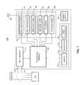
- FIG. 1depicts a schematic diagram of an exemplary IED, e.g., power quality analyzer, in accordance with one embodiment of the present disclosure.
- FIG. 2is a high-level block diagram of an input module of the power quality analyzer of FIG. 1 .
- FIG. 3is a high-level block diagram of a processing module of the power quality analyzer of FIG. 1 .
- FIG. 4is a schematic diagram illustrating connectivity and networking features of the power quality analyzer of FIG. 1 in accordance with one embodiment of the present disclosure.
- FIG. 5is a schematic diagram illustrating connectivity and networking features of the power quality analyzer of FIG. 1 in accordance with another embodiment of the present disclosure.
- FIG. 6is a timing diagram illustrating techniques for waveform sampling used in the power quality analyzer of FIG. 1 .
- FIG. 7is a timing diagram illustrating techniques for averaging data points used in the power quality analyzer of FIG. 1 .
- FIG. 8is a timing diagram illustrating techniques for displaying data used in the power quality analyzer of FIG. 1 .
- FIG. 9is a flow chart illustrating a method of operating the power quality analyzer of FIG. 1 .
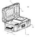
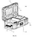
- FIG. 10is a perspective view of a portable power quality analyzer in accordance with another embodiment of the present disclosure.
- particular method steps of the discussed methodsare performed in the depicted order. In alternate embodiments, in the respective methods, at least two method steps or portions thereof may be performed contemporaneously, in parallel, or in a different order.
- processoror “controller” should not be construed to refer exclusively to hardware capable of executing software, and may implicitly include, without limitation, digital signal processor (“DSP”) hardware, read only memory (“ROM”) for storing software, random access memory (“RAM”), and nonvolatile storage.
- DSPdigital signal processor
- ROMread only memory
- RAMrandom access memory
- any switches shown in the figuresare conceptual only. Their function may be carried out through the operation of program logic, through dedicated logic, through the interaction of program control and dedicated logic, or even manually, the particular technique being selectable by the implementer as more specifically understood from the context.
- IEDsintelligent electronic devices
- power quality analyzerssuch as power quality analyzers, including portable and accuracy certifiable power quality analyzers.
- power quality analyzersis broadly used herein in reference to IEDs adapted to record, measure, and communicate at least some of parameters of waveforms of voltages and currents of a respective electrical service, including their harmonics, transients, ripples, and other disturbances.
- portableis used in reference to the power quality analyzers to denote transportability of such IEDs and ability thereof for momentarily, temporary, and permanent connectivity to respective electrical services and communication networks.
- IEDsProgrammable Logic Controllers
- RTUsRemote Terminal Units
- protective relaysfault recorders
- metersmeters
- exemplaryis used herein to mean “serving as an example, instance, or illustration.” Any configuration or design described herein as “exemplary” is not necessarily to be construed as preferred or advantageous over other configurations or designs.
- the phrase “coupled with”is defined to mean directly connected to or indirectly connected with through one or more intermediate components. Such intermediate components may include both hardware and software based components.
- FIG. 1depicts a schematic diagram illustrating an exemplary power quality analyzer (referred to hereafter as “PQ analyzer”) 100 .
- the PQ analyzer 100generally comprises an input module 110 , a processing module 120 , an optional user interface unit 130 , a communications module 140 , and a power supply 150 .
- the PQ analyzer 100determines power quality parameters of electrical services 101 .
- the power supply 150 of the PQ analyzer 100may be coupled to the power lines of the electrical services 101 or, alternatively, to an independent source of power.
- the PQ analyzer 100is operable to monitor, calculate, and analyze at least some of voltage/current fault signatures, voltage surges and sags, voltage flickers, neutral-to-ground voltage fluctuations, voltage/current harmonics and interharmonics, voltage/current total harmonic distortion (THD), voltage/current transient events and sub-cycle transient events, i.e., power quality events. It is to be appreciated that this listing of power quality events is not exhaustive and other types of events and/or disturbances may be classified as power quality events.
- the PQ analyzer 100also will determine real power, reactive power, total power, and power factors, among other parameters of particular electrical services 101 . In alternate embodiment, additionally or alternatively, the PQ analyzer 100 may also be configured to determine line/phase voltages and currents or root mean square (RMS) values thereof, as well as calculate energy or revenue.
- RMSroot mean square
- the PQ analyzer 100performs automatic accuracy calibrations and temperature compensations and may be programmed (i.e., configured) for time stamping of collected data, accumulating the data during pre-scheduled time intervals and/or per an event-triggered schedule, reporting the data with pre-scheduled periodicity, as well as for storing, displaying, and transmitting pre-event and post-event portions of waveforms of monitored voltages and currents of the electrical services 101 .
- power lines of the electrical services 101illustratively include phase lines A, B, and C and a neutral line N, which are coupled to the PQ analyzer 100 using voltage interface 112 and current interface 114 .
- the electrical services 101may have custom wiring configurations, for example, single-phase, dual-phase, Wye, Delta, or multi-phase wiring configurations, as well as include DC electrical services.
- the electrical services 101may include pluralities of sub-sets of phase lines and/or subsets including phase and neutral lines.
- at least a portion of the power linesmay be represented by voltage/current wiring pairs forming the interfaces 112 , 114 .
- the input module 110comprises a voltage input terminal 202 , a current input terminal 204 , sensing circuits 210 including voltage dividers 212 and current sensors 214 , an optional multi-channel gain control unit 220 including voltage ( 222 ) and current ( 224 ) gain control circuits (GCCs), and a digitizing unit 230 .
- sensing circuits 210including voltage dividers 212 and current sensors 214
- an optional multi-channel gain control unit 220including voltage ( 222 ) and current ( 224 ) gain control circuits (GCCs)
- GCCsgain control circuits
- the input module 110is coupled to the voltage and current interfaces 112 and 114 of the electrical service 101 .
- the voltage inputs 112 and the current inputs 114are selectively connected to voltage dividers 306 and current sensors 308 , respectively.
- Output signals of the voltage dividers 212 and current sensors 214are selectively provided to inputs of the voltage GCC 222 and current GCCs 224 optimizing gain factors of the output signals.
- the digitizing unit 230waveforms of the gain-optimized analog output signals of the voltage dividers 212 and current sensors 214 are digitized using analog-to-digital converters (ADCs).
- ADCsanalog-to-digital converters
- the digitizing unit 230comprises a voltage digitizing module 240 and a current digitizing module 250 .
- the modules 240 , 250include blocks of ADCs selectively used in Fast Fourier Transform (FFT) analysis (ADCs 244 , 252 ) and waveform analysis (ADCs 244 , 254 ) of the monitored voltages (ADCs 242 , 244 ) and currents (ADCs 252 , 254 ) of the electrical services 101 .
- FFTFast Fourier Transform
- each of these blocks of ADCsincludes dedicated devices selectively performing, in real time, digitizing of particular voltage and current waveforms.
- the digitized voltage/current waveformsare transferred, via serial or parallel interface 206 (for example, Serial Peripheral Interface (SPI)), to the processing module 120 .
- serial or parallel interface 206for example, Serial Peripheral Interface (SPI)
- a sampling rate of the ADCs 242 and 252is in range from about 12 to 36 KHz, which corresponds to about 200-600 data points per a cycle of a voltage/current waveform at the AC frequency of 60 Hz.
- the sampling rate of the ADCs 242 and 252is about 26 KHz, and a sampling rate of the ADCs 244 and 254 is up to 10 MHz.
- Such a high sampling rate of the ADCs 244 and 254allows performing in the PQ analyzer 100 extensive high-resolution data processing and analysis of transients in the monitored voltages and currents.
- the processing module 120comprises a central processor 310 having an internal memory 312 , a memory module 320 , an input module controller 330 , a communications controller 340 , a user interface controller 350 , a real time clock 360 , a power backup 370 , and support circuits 380 .
- the memory 320illustratively includes a RAM 322 , a flash memory 324 , and an EEPROM 326 .
- Non-volatile portions of the memory 320contain codes of programs and software modules that, together, support various functions of the PQ analyzer 100 . Such functions generally include execution of various power quality related measurements and calculations and facilitation of user interface and wireless/wired connectivity of the PQ analyzer 100 .
- the memory 320contains code of a program that configures the PQ analyzer 100 to operate as a terminal or a server of a Wi-Fi network, a cellular network, an Intranet, a local area network (LAN), a wide area network (WAN), or the Internet.
- the user interface unit 130generally includes a front panel display 132 (e.g., liquid crystal display (LCD) or plasma display), indicators 134 (e.g., LED indicators), and user controls 136 .
- the user controls 136may include pushbuttons that allow to select particular data for being shown on the display 132 , select/modify configuration settings of the PQ analyzer 100 , or review status messages generated by the PQ analyzer.
- the user interface unit 130includes a touch-screen display 132 , which may be used to review and/or modify configuration settings of the PQ analyzer 100 . Alternatively or additionally, such operations may be performed via the communication module 140 or using the user controls 136 .
- the communications module 140comprises a Wi-Fi transceiver 141 , an optional Short Massaging Service (SMS) transceiver 143 , and optional network communication device 142 , input/output (I/O) card(s) 144 , infra-red (IR) transceiver 146 , and wireless communication device 148 , and a transmit/receive antenna 149 selectively coupled to the transceivers 141 , 143 and communication device 148 .
- SMSShort Massaging Service
- I/Oinput/output
- IRinfra-red
- a format of incoming portions of the informationcomprises a field for a pre-defined address of the PQ analyzer 100 , a field for an address of a sending party, and a field for a command.
- a format of outgoing portions of the informationcomprises a field for an address of an intended receiving party, a field for an address of the PQ analyzer 100 , and a field for outgoing data. Both the incoming and outgoing portions of the information may be password-protected or encrypted.
- the PQ analyzer 100can transmit and receive information formatted using one or more standard data protocols.
- the communication module 140may be configured to transmit/receive information using the Hypertext Transfer Protocol (HTML), the File Transfer Protocol (FTP), or the Extensive Markup Language (XML) Protocol, as well as perform real-time conversions between these protocols.
- HTTPHypertext Transfer Protocol
- FTPFile Transfer Protocol
- XMLExtensive Markup Language
- the outgoing informationgenerally comprises present or historic raw or systemized data, alarms, text/symbolic messages, charts, and bar graphs.
- examples of the incoming informationmay include PQ analyzer's configuration settings, requests for data or status information, and the like.
- the PQ analyzer 100may produce information in a form of web pages allowing access to particular portions of the data or configuration settings of the PQ analyzer. Both the incoming and outgoing information may be in a form of email messages.
- configuration settings and procedures executed by the PQ analyzer 100are wirelessly upgradeable via the WI-Fi transceiver 141 , SMS transceiver 141 , and/or wireless communication device 148 .
- the Wi-Fi transceiver 141provides the PQ analyzer 100 with wireless transmission and reception capabilities commonly referred to as Wi-Fi, or IEEE 802.11.X connectivity, wherein X denotes a version of the communication standard IEEE 802.11.
- the PQ analyzer 100can be communicatively connected to a local Wi-Fi base unit 410 .
- the Wi-Fi base unit 410may be connected to a network 420 (for example, Intranet, LAN, or WAN) using a wired interface 402 (Wi-Fi base unit 410 A) or a wireless interface 404 (Wi-Fi base unit 410 B).
- the network 420is communicatively coupled to the Internet 430 .
- the PQ analyzer 100is accessible by users 440 , such as service/line personnel of utility companies providing electric services 101 or owners of loads which voltages and currents are monitored using the PQ analyzer 100 .
- the Dynamic Host Configuration Protocolmay be used to assign Internet addresses to the PQ analyzer 100 .
- the users 440may also access the PQ analyzer 100 via the network 420 (shown, in phantom, with a link 406 ) or directly via the I/O card(s) 144 and/or the IR transceiver 146 (shown, in phantom, with a link 408 ).
- the PQ analyzer 100may simultaneously exchange information (e.g., data, alarms, etc.) with a plurality of the users thereof using communication protocols and formats discussed above in reference to the communication module 140 and, in particular, using e-mail formats.
- a plurality of PQ analyzers 100are employed to create an ad hoc network for power monitoring.
- one of the plurality of PQ analyzers 100is configured as a server to collect data from the other PQ analyzers 100 and to serve this collected information over a different network, e.g., the Internet.
- the ad hoc networkis self-configuring and each PQ analyzers 100 will include a wireless connection signal strength indictor.
- the plurality of PQ analyzers 100will communication with each other and determine which PQ analyzer 100 has the highest signal strength to a base unit, e.g., WFI base unit 410 B, and will select the PQ analyzer 100 with the highest signal strength as the server.
- the remaining PQ analyzers 100will be terminals or client of the ad hoc network. This will ensure reliability of the network so if a PQ analyzer 100 will low signal strength continuously “falls off” the network only that terminal or client will be lost and not the whole network as in the case where the PQ analyzer 100 with the lowest signal strength is the server.
- the ad hoc network of PQ analyzers 100will be beneficial for temporarily setting up a network in a facility to determine locations and causes of power quality events and disturbances.
- the SMS transceiver 143provides the PQ analyzer 100 with wireless connectivity via regional cellular networks.
- the SMS transceiver 143typically, due to size limitations of SMS transmissions, in incoming/outgoing SMS messages at least a portion of commands and data is presented in pre-defined coded formats, and different such formats may be used in communications with particular users of the PQ analyzer 100 .
- the PQ analyzer 100is communicatively connected to a base station(s) 510 of a regional cellular network.
- the base stations 510may be connected to the network 420 via wireless and/or wired interfaces 502 , 504 .
- the PQ analyzer 100is assigned a cellular phone number and, via the respective base station 510 , is communicatively accessible by user of cellular phones 520 .
- the PQ analyzer 100may selectively transmit/receive information (e.g., data or alarms) to/from users of particular cellular phones 520 , for example, to/from traveling users 440 (discussed above in reference to FIG. 4 ).
- the wireless communication device 148may include BluetoothTM connectivity, satellite connectivity, as well as interfaces to wireless systems employing spread-spectrum techniques, ZigBee systems (i.e., systems compliant with the IEEE 802.15.4 standard for wireless personal area networks wireless (WPANs)), or mesh-enabled communication systems.
- BluetoothTM connectivitysatellite connectivity
- wireless systemsemploying spread-spectrum techniques
- ZigBee systemsi.e., systems compliant with the IEEE 802.15.4 standard for wireless personal area networks wireless (WPANs)
- mesh-enabled communication systemsi.e., systems compliant with the IEEE 802.15.4 standard for wireless personal area networks wireless (WPANs)
- the network communication device 142provides connectivity between the PQ analyzer 100 and wired networks (for example, via a hardware/software modem or network interface card (NIC)) and, structurally, includes one or more specialized cards or modules.
- the network communication device 142supports the TCP/IP and 10/100Base-T Ethernet communication protocols and, optionally, at least one of the Modbus, Modbus/TCP, Distributed Network Protocol (DNP) (e.g., DNP 3.0), RS-485, and RS-232 communication protocols.
- DNPDistributed Network Protocol
- the network communication device 142may be used for operations otherwise performed in the PQ analyzer 100 using the Wi-Fi transceiver 141 or SMS transceiver 143 .
- the I/O cards 144selectively provide to remote users of the PQ analyzer 100 industry-standard 0-1 mA interface, 4-20 mA current loop interface, and digital ON/OFF input/output contacts, and the IR I/O transceiver 146 supports optical communications with IR-enabled devices, such as Personal Digital Assistants (PDAs), laptops, and the like.
- PDAsPersonal Digital Assistants
- the network communication device 142 and the I/O cards 144 , 146are generally coupled to the processing module 120 using serial interfaces, for example, DNP, Modbus, Serial Peripheral Interface (SPI), RS-232, or RS-485 interfaces.
- the PQ analyzer 100may be configured to include up to two of the same or different I/O cards (i.e., printed circuit boards (PCBs)) 144 .
- the physical connectionsmay include, but not limited to, cabling (e.g., parallel or serial cables, including RS-232, RS-485, USB, and Firewire (IEEE-1394) Ethernet, Fiber Optic, or Fiber Optic over Ethernet cables, and appropriate port configurations.
- FIG. 6depicts a timing diagram 600 illustrating techniques for waveform sampling used in the PQ analyzer 100 .
- the input module 110detects moments of time (x-axis 604 ) when polarity of a waveform 601 (y-axis 602 ) changes from negative to positive (i.e., when the rising waveform 601 crosses the x-axis 604 ) and produces a zero-crossing signal. Such moments are referred to as zero-crossing points and are denoted as T 0 . A leading edge of the zero-crossing signal (not shown) coincides, in each cycle of the waveform 601 , with the moments T 0 .
- the ADCsare synchronized with the zero-crossing signal and generate data points 612 with periodicity determined be their respective sampling rates (as depicted, at moments T 0 -T 11 ).
- the zero-crossing pointsmay correspond to moments T 6 , in which polarity of the waveform 601 changes from positive to negative.
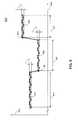
- FIG. 7is timing diagram 700 illustrating techniques for averaging data points used in the PQ analyzer 100 .
- the timing diagram 700depicts a waveform 710 of voltage (or current) (y-axis 702 ) as a function of time (x-axis 704 ).
- the waveformis shown as a band having noise-defined boundaries 710 A and 710 B . At any moment of time, a measured value is disposed in the respective portion of such a band.
- data points 716 A - 716 Dare measured at exemplary moments t A -t D corresponding to the same phase angles in their respective AC cycles, and their numerical values are randomly disposed in a range 712 , which is defined by the boundaries 710 A and 710 B .
- pluralities of data points corresponding, in the respective AC cycles, to the same phase angles thereofare selectively measured and identified.
- Such data pointsare disposed, on the x-axis 704 , at the same distances from the corresponding zero-crossing points 706 , which are defined as discussed above in reference to FIG. 6 .
- data points 716 A - 716 Dcorrespond to the same phase angle and are disposed, in their respective AC cycles, at the same distances 714 away from the zero-crossing points 706 .
- Values Q of the data points 716 A - 716 Dare averaged for a pre-determined number m of cycles of the waveform 710 , wherein m>1 (for example, four data points 716 A - 716 D are averaged) or during a pre-determined time interval 740 . Then, averaged values of the data points 716 A - 716 D are used in the calculations performed in the processing module 120 . In operation, averaging of consecutive data points corresponding to the same phase angles allows to suppress analog noise in the measurements of the monitored voltages and currents approximately by a factor of ⁇ (Q 1 ) 2 +(Q 2 ) 2 + . . . +(Q m ) 2 ⁇ 1/2 .
- FIG. 8is a timing diagram illustrating techniques for displaying data used in the PQ analyzer 100 .
- the timing diagram 800depicts a plurality of data points 810 , 820 , and 830 depicting a value (y-axis 802 ) of an arbitrary parameter G as a function of time (x-axis 804 ).
- this conditionis met at data points denoted using reference numerals 801 and 803 .
- This techniqueallows filtering digital noise associated with the measurements and calculations of the displayed parameters G.
- a periodicity of calculating a consecutive value of the weighted average F 2may be substantially greater then a refreshing rate of the display 132 .
- FIG. 9depicts a high-level flow diagram of a method 900 for operating the PQ analyzer 100 in accordance with one embodiment of the present disclosure.
- monitored voltages and supply currents of the electrical service 101are sensed using the voltage dividers 212 and currents sensors 214 of the input module 110 .
- gain factors of the voltage dividers and currents sensorsare selectively adjusted and, at step 930 , gain-adjusted waveforms of the monitored voltages and currents are digitized using the ADCs of the digitizing module 230 .
- the PQ analyzer 100analyzes waveforms of the monitored voltages and currents, and, using the processing module 120 , performs calculations of power quality parameters thereof.
- the results of these calculationsare displayed on the front panel display 132 and, using component devices of the communications module 140 (for example, Wi-Fi transceiver 141 ), are transmitted to the respective addressee(s) of the PQ analyzer 100 .
- Outgoing data transmissionsmay be performed on demand or with pre-determined periodicity, whereas alarms/incoming messages may be communicated during execution of any step of the method 900 .
- the PQ analyzeris disposed in a portable enclosure.
- the PQ analyzer 1000is constructed in a watertight enclosure 1002 , e.g., a rugged carrying case, for housing the various components described above.
- the enclosure 1002is watertight and outdoor rated (e.g., a NEMA 4 rated enclosure) and includes watertight input terminations for the voltage interface 112 and current interface 114 . This enables the portable PQ analyzer 1000 to be used in harsh environments or outside the incoming utility feed to a building.
- the enclosure 1002includes a handle 1004 for carrying the PQ analyzer 1000 from monitoring site to monitoring site.
- the user interface unit 130is a touch screen graphical display, e.g., an LCD touch screen display.
- the touch screen displaywill enable a user to enter information such as setup parameters, calibration factors, limits, etc.
- the touch screen displayallows real-time data to be displayed at the portable PQ analyzer 1000 easily and immediately without having to download the data to a computer or connecting the PQ analyzer 1000 to a computer.
- the touch screen displaywill also display various data recorded and calculated by the portable PQ analyzer 1000 such as voltage and current waveforms, harmonics, alarms, phasor diagrams, trending, etc.
- the PQ analyzer 1000does include a RS232 download port 1005 for downloading and remote viewing of, for example, historical logs and other large volumes of data.
- the portable PQ analyzer 1000may be powered using two different methods, e.g., field powered and plug powered.
- the first methodallows the PQ analyzer 1000 to be powered from a voltage line connection using two phase inputs via the voltage interface 112 .
- the second methodutilizes a wall plug for remotely powering the PQ analyzer 1000 .
- the PQ analyzer 1000includes a 120/220 volt plug receptacle 1006 for powering the PQ analyzer 1000 with a wall plug.
- Switch 1008enables a user to select the power mode, e.g., line power connection or plug power connection.
- the portable PQ analyzer 1000will have a watertight connection for coupling the transmit/receive antenna 149 to the PQ analyzer 1000 when the enclosure or case 1002 is closed.
- the antennawill be a wound, flat coil 1011 disposed on an upper cover 1009 of the case. In this manner, the antenna can be relatively long to increase its ability to pick-up wireless connection signals.
- the antenna 1011is wound to be disposed substantially over the entire surface area of the cover 1109 .
- the case 1002can be closed while operational ensuring the contents of the enclosure or case 1002 are protected from the environment conditions.
Landscapes
- General Physics & Mathematics (AREA)
- Physics & Mathematics (AREA)
- Engineering & Computer Science (AREA)
- Business, Economics & Management (AREA)
- Economics (AREA)
- Health & Medical Sciences (AREA)
- Human Resources & Organizations (AREA)
- Strategic Management (AREA)
- Water Supply & Treatment (AREA)
- General Health & Medical Sciences (AREA)
- Power Engineering (AREA)
- Marketing (AREA)
- Primary Health Care (AREA)
- Public Health (AREA)
- Tourism & Hospitality (AREA)
- General Business, Economics & Management (AREA)
- Theoretical Computer Science (AREA)
- Selective Calling Equipment (AREA)
- Telephonic Communication Services (AREA)
- Arrangements For Transmission Of Measured Signals (AREA)
- Remote Monitoring And Control Of Power-Distribution Networks (AREA)
Abstract
Description
Claims (12)
Priority Applications (1)
| Application Number | Priority Date | Filing Date | Title |
|---|---|---|---|
| US12/197,341US9696180B2 (en) | 2004-10-20 | 2008-08-25 | Portable power quality analyzer with networking capabilities |
Applications Claiming Priority (3)
| Application Number | Priority Date | Filing Date | Title |
|---|---|---|---|
| US10/969,706US7304586B2 (en) | 2004-10-20 | 2004-10-20 | On-line web accessed energy meter |
| US11/998,920US7999696B2 (en) | 2004-10-20 | 2007-12-03 | On-line web accessed energy meter |
| US12/197,341US9696180B2 (en) | 2004-10-20 | 2008-08-25 | Portable power quality analyzer with networking capabilities |
Related Parent Applications (1)
| Application Number | Title | Priority Date | Filing Date |
|---|---|---|---|
| US11/998,920ContinuationUS7999696B2 (en) | 2004-10-20 | 2007-12-03 | On-line web accessed energy meter |
Publications (2)
| Publication Number | Publication Date |
|---|---|
| US20080312851A1 US20080312851A1 (en) | 2008-12-18 |
| US9696180B2true US9696180B2 (en) | 2017-07-04 |
Family
ID=36180197
Family Applications (6)
| Application Number | Title | Priority Date | Filing Date |
|---|---|---|---|
| US10/969,706Expired - LifetimeUS7304586B2 (en) | 2004-10-20 | 2004-10-20 | On-line web accessed energy meter |
| US11/998,920Active2026-11-29US7999696B2 (en) | 2004-10-20 | 2007-12-03 | On-line web accessed energy meter |
| US12/197,341Expired - Fee RelatedUS9696180B2 (en) | 2004-10-20 | 2008-08-25 | Portable power quality analyzer with networking capabilities |
| US13/209,896Expired - LifetimeUS8599036B2 (en) | 2004-10-20 | 2011-08-15 | On-line web accessed energy meter |
| US14/093,644Active2025-11-28US10641618B2 (en) | 2004-10-20 | 2013-12-02 | On-line web accessed energy meter |
| US16/824,741Expired - LifetimeUS11754418B2 (en) | 2004-10-20 | 2020-03-20 | On-line web accessed energy meter |
Family Applications Before (2)
| Application Number | Title | Priority Date | Filing Date |
|---|---|---|---|
| US10/969,706Expired - LifetimeUS7304586B2 (en) | 2004-10-20 | 2004-10-20 | On-line web accessed energy meter |
| US11/998,920Active2026-11-29US7999696B2 (en) | 2004-10-20 | 2007-12-03 | On-line web accessed energy meter |
Family Applications After (3)
| Application Number | Title | Priority Date | Filing Date |
|---|---|---|---|
| US13/209,896Expired - LifetimeUS8599036B2 (en) | 2004-10-20 | 2011-08-15 | On-line web accessed energy meter |
| US14/093,644Active2025-11-28US10641618B2 (en) | 2004-10-20 | 2013-12-02 | On-line web accessed energy meter |
| US16/824,741Expired - LifetimeUS11754418B2 (en) | 2004-10-20 | 2020-03-20 | On-line web accessed energy meter |
Country Status (1)
| Country | Link |
|---|---|
| US (6) | US7304586B2 (en) |
Cited By (4)
| Publication number | Priority date | Publication date | Assignee | Title |
|---|---|---|---|---|
| US10628053B2 (en) | 2004-10-20 | 2020-04-21 | Electro Industries/Gauge Tech | Intelligent electronic device for receiving and sending data at high speeds over a network |
| US10641618B2 (en) | 2004-10-20 | 2020-05-05 | Electro Industries/Gauge Tech | On-line web accessed energy meter |
| US10845399B2 (en) | 2007-04-03 | 2020-11-24 | Electro Industries/Gaugetech | System and method for performing data transfers in an intelligent electronic device |
| US11686749B2 (en) | 2004-10-25 | 2023-06-27 | El Electronics Llc | Power meter having multiple ethernet ports |
Families Citing this family (122)
| Publication number | Priority date | Publication date | Assignee | Title |
|---|---|---|---|---|
| US7994934B2 (en) | 2004-10-05 | 2011-08-09 | Electro Industries/Gauge Tech | Meter having a communication interface for receiving and interfacing with a communication device |
| US7616656B2 (en)* | 2004-10-20 | 2009-11-10 | Electron Industries / Gauge Tech | System and method for providing communication between intelligent electronic devices via an open channel |
| US7609719B2 (en) | 2004-10-12 | 2009-10-27 | Electro Industries/Gauge Tech | System and method for simultaneous communication on modbus and DNP 3.0 over Ethernet for electronic power meter |
| US7388189B2 (en)* | 2004-10-27 | 2008-06-17 | Electro Industries/Gauge Tech | System and method for connecting electrical devices using fiber optic serial communication |
| US7271996B2 (en)* | 2004-12-03 | 2007-09-18 | Electro Industries/Gauge Tech | Current inputs interface for an electrical device |
| US7184904B2 (en)* | 2005-01-20 | 2007-02-27 | Electro Industries/Gaugetech | System and method for providing universal additional functionality for power meters |
| US8581169B2 (en)* | 2005-01-24 | 2013-11-12 | Electro Industries/Gauge Tech | System and method for data transmission between an intelligent electronic device and a remote device |
| US8190381B2 (en) | 2005-01-27 | 2012-05-29 | Electro Industries/Gauge Tech | Intelligent electronic device with enhanced power quality monitoring and communications capabilities |
| US8160824B2 (en) | 2005-01-27 | 2012-04-17 | Electro Industries/Gauge Tech | Intelligent electronic device with enhanced power quality monitoring and communication capabilities |
| US8620608B2 (en) | 2005-01-27 | 2013-12-31 | Electro Industries/Gauge Tech | Intelligent electronic device and method thereof |
| US8930153B2 (en) | 2005-01-27 | 2015-01-06 | Electro Industries/Gauge Tech | Metering device with control functionality and method thereof |
| US7761226B1 (en)* | 2005-07-27 | 2010-07-20 | The United States Of America As Represented By The Secretary Of The Navy | Interactive pedestrian routing system |
| US7554320B2 (en) | 2005-10-28 | 2009-06-30 | Electro Industries/Gauge Tech. | Intelligent electronic device for providing broadband internet access |
| US8933815B2 (en) | 2005-10-28 | 2015-01-13 | Electro Industries/Gauge Tech | Intelligent electronic device having an XML-based graphical interface |
| US20120010831A1 (en) | 2005-10-28 | 2012-01-12 | Electro Industries/Gauge Tech | Intelligent electronic device having a programmable display |
| US8515348B2 (en) | 2005-10-28 | 2013-08-20 | Electro Industries/Gauge Tech | Bluetooth-enable intelligent electronic device |
| US8442660B2 (en) | 2005-10-28 | 2013-05-14 | Electro Industries/Gauge Tech | Intelligent electronic device having audible and visual interface |
| GB2437342B (en)* | 2006-04-19 | 2010-09-15 | Actaris Uk Ltd | Method for configuring parameters of GPRS-type communication devices over a cellular phone network, and corresponding communications system |
| CA2656405A1 (en)* | 2006-06-29 | 2008-01-10 | Carina Technology, Inc. | System and method for controlling a utility meter |
| US20080040296A1 (en)* | 2006-08-10 | 2008-02-14 | V2 Green Inc. | Electric Resource Power Meter in a Power Aggregation System for Distributed Electric Resources |
| US7843897B2 (en)* | 2006-10-30 | 2010-11-30 | Schweitzer Engineering Laboratories, Inc. | System, apparatus and method for mixed mode communication on a single network |
| GB0624582D0 (en)* | 2006-12-08 | 2007-01-17 | Visible Computing Ltd | USB autorun devices |
| US9885739B2 (en) | 2006-12-29 | 2018-02-06 | Electro Industries/Gauge Tech | Intelligent electronic device capable of operating as a USB master device and a USB slave device |
| US9063181B2 (en) | 2006-12-29 | 2015-06-23 | Electro Industries/Gauge Tech | Memory management for an intelligent electronic device |
| US20080235143A1 (en)* | 2007-03-20 | 2008-09-25 | Square D Company | Real time data tunneling for utility monitoring web applications |
| US7920976B2 (en) | 2007-03-27 | 2011-04-05 | Electro Industries / Gauge Tech. | Averaging in an intelligent electronic device |
| US20130275066A1 (en) | 2007-04-03 | 2013-10-17 | Electro Industries/Gaugetech | Digital power metering system |
| US11307227B2 (en) | 2007-04-03 | 2022-04-19 | Electro Industries/Gauge Tech | High speed digital transient waveform detection system and method for use in an intelligent electronic device |
| US9989618B2 (en) | 2007-04-03 | 2018-06-05 | Electro Industries/Gaugetech | Intelligent electronic device with constant calibration capabilities for high accuracy measurements |
| GB0803140D0 (en)* | 2008-02-21 | 2008-03-26 | Sentec Ltd | Technique for inference of multiple appliances' power use from single point measurements |
| US12061218B2 (en) | 2008-03-13 | 2024-08-13 | Ei Electronics Llc | System and method for multi-rate concurrent waveform capture and storage for power quality metering |
| US9482555B2 (en) | 2008-04-03 | 2016-11-01 | Electro Industries/Gauge Tech. | System and method for improved data transfer from an IED |
| US20090319905A1 (en)* | 2008-06-23 | 2009-12-24 | Tellemotion, Inc. | System and method for realtime monitoring of resource consumption and interface for the same |
| US7859403B2 (en)* | 2008-08-06 | 2010-12-28 | Elecsys Corporation | Monitoring and alarming system and method |
| JP5655011B2 (en)* | 2009-02-20 | 2015-01-14 | アクララ パワー−ライン システムズ インコーポレイテッド | Wireless broadband communication network for utilities |
| US8477794B2 (en)* | 2009-04-30 | 2013-07-02 | Elster Electricity, Llc | Multiple communications protocol routing in advanced metering infrastructure context |
| GB0911902D0 (en)* | 2009-07-09 | 2009-08-19 | Remote Energy Monitoring Holding | Near real time commodity display system |
| US20110035063A1 (en)* | 2009-10-20 | 2011-02-10 | Saju Anthony Palayur | Water Management System |
| USD712289S1 (en) | 2009-12-01 | 2014-09-02 | Electro Industries/Gauge Tech | Electronic meter |
| US20110153108A1 (en)* | 2009-12-18 | 2011-06-23 | Electronics And Telecommunications Research Institute | Method and device for remote power management |
| JP2011211435A (en)* | 2010-03-29 | 2011-10-20 | Kyocera Corp | Communication repeater |
| US8350718B2 (en) | 2010-05-04 | 2013-01-08 | Itron, Inc. | Secure collector diagnostic portal activation |
| US20130070651A1 (en)* | 2010-05-27 | 2013-03-21 | Kyocera Corporation | Power line communication device, security level setting method, and storage medium storing security level setting program |
| EP3324153A1 (en) | 2010-07-29 | 2018-05-23 | Power Monitors, Inc. | Method and apparatus for a demand management monitoring system |
| US10060957B2 (en) | 2010-07-29 | 2018-08-28 | Power Monitors, Inc. | Method and apparatus for a cloud-based power quality monitor |
| CN103998942A (en) | 2010-12-13 | 2014-08-20 | 美国弗劳恩霍夫股份公司 | Method and system for non-intrusive load monitoring |
| US8635036B2 (en) | 2011-01-04 | 2014-01-21 | General Electric Company | Systems, methods, and apparatus for providing energy management utilizing a power meter |
| US20120179396A1 (en)* | 2011-01-12 | 2012-07-12 | General Electric Company | Systems, methods, and apparatus for powering an ami communication board |
| US8554739B2 (en)* | 2011-01-13 | 2013-10-08 | Schweitzer Engineering Laboratories Inc. | Systems and methods for IED design templates |
| CA2870452C (en) | 2011-04-15 | 2020-03-10 | Dominion Energy Technologies, Inc. | System and method for single and multi zonal optimization of utility services delivery and utilization |
| CA2874132A1 (en) | 2011-06-09 | 2013-01-17 | Dominion Energy Technologies, Inc. | System and method for grid based cyber security |
| US8929391B2 (en) | 2011-06-22 | 2015-01-06 | Schweitzer Engineering Laboratories, Inc. | Systems and methods for communications devices having multiple interfaces |
| US8677464B2 (en) | 2011-06-22 | 2014-03-18 | Schweitzer Engineering Laboratories Inc. | Systems and methods for managing secure communication sessions with remote devices |
| WO2013020053A1 (en) | 2011-08-03 | 2013-02-07 | Power Tagging Technologies, Inc. | System and methods for synchronizing edge devices on channels without carrier sense |
| KR101216767B1 (en)* | 2011-09-09 | 2012-12-28 | 엘에스산전 주식회사 | Method for processing data and electromechanical relay |
| KR101268712B1 (en)* | 2011-09-29 | 2013-05-28 | 한국전력공사 | System and method for detecting power quality abnormal waveform of the electric power distribution system |
| US20150356104A9 (en) | 2011-10-04 | 2015-12-10 | Electro Industries/Gauge Tech | Systems and methods for collecting, analyzing, billing, and reporting data from intelligent electronic devices |
| US10275840B2 (en) | 2011-10-04 | 2019-04-30 | Electro Industries/Gauge Tech | Systems and methods for collecting, analyzing, billing, and reporting data from intelligent electronic devices |
| US10303860B2 (en) | 2011-10-04 | 2019-05-28 | Electro Industries/Gauge Tech | Security through layers in an intelligent electronic device |
| US10771532B2 (en) | 2011-10-04 | 2020-09-08 | Electro Industries/Gauge Tech | Intelligent electronic devices, systems and methods for communicating messages over a network |
| US12260078B2 (en) | 2011-10-04 | 2025-03-25 | Ei Electronics Llc | Dynamic webpage interface for an intelligent electronic device |
| US10862784B2 (en) | 2011-10-04 | 2020-12-08 | Electro Industries/Gauge Tech | Systems and methods for processing meter information in a network of intelligent electronic devices |
| CN102496260B (en)* | 2011-11-23 | 2013-01-23 | 青岛乾程电子科技有限公司 | Multiple communication technology type of method for electric power information acquisition control |
| CN102565583A (en)* | 2012-01-04 | 2012-07-11 | 天津市电力公司 | Power quality monitoring terminal for switch-in electronic mutual inductor |
| US20130174249A1 (en)* | 2012-01-04 | 2013-07-04 | Itron, Inc. | Secure lock function for an endpoint |
| CN102495276B (en)* | 2012-01-04 | 2014-02-26 | 山东电力研究院 | A measurement method using a high-voltage power consumption testing device |
| CN102608467B (en)* | 2012-03-22 | 2014-09-03 | 深圳供电局有限公司 | Transient power quality analysis method and system |
| CN103576020A (en)* | 2012-08-08 | 2014-02-12 | 成都博课启睿科技有限公司 | Power quality monitoring system based on network |
| CN102821220B (en)* | 2012-08-08 | 2015-12-02 | 广东电网公司汕头供电局 | There is the energy-saving service systems of electrical energy consumption analysis |
| US9721259B2 (en)* | 2012-10-08 | 2017-08-01 | Accenture Global Services Limited | Rules-based selection of counterfeit detection techniques |
| US9130945B2 (en) | 2012-10-12 | 2015-09-08 | Schweitzer Engineering Laboratories, Inc. | Detection and response to unauthorized access to a communication device |
| CN103809148B (en)* | 2012-11-12 | 2016-12-21 | 深圳供电局有限公司 | Method and system for measuring dynamic characteristics of electric energy meter |
| US10330713B2 (en) | 2012-12-21 | 2019-06-25 | Electro Industries/Gauge Tech | Intelligent electronic device having a touch sensitive user interface |
| US10097240B2 (en) | 2013-02-19 | 2018-10-09 | Astrolink International, Llc | System and method for inferring schematic and topological properties of an electrical distribution grid |
| US20160003874A1 (en)* | 2013-02-25 | 2016-01-07 | Isabellenhütte Heusler Gmbh & Co. Kg | Measuring system having several sensors and having a central evaluating unit |
| US9288215B2 (en) | 2013-03-08 | 2016-03-15 | Itron, Inc. | Utilizing routing for secure transactions |
| US11816465B2 (en) | 2013-03-15 | 2023-11-14 | Ei Electronics Llc | Devices, systems and methods for tracking and upgrading firmware in intelligent electronic devices |
| US9438312B2 (en) | 2013-06-06 | 2016-09-06 | Astrolink International Llc | System and method for inferring schematic relationships between load points and service transformers |
| JP2016521962A (en) | 2013-06-13 | 2016-07-25 | アストロリンク インターナショナル エルエルシー | Estimate the feed lines and phases that power the transmitter |
| MX357831B (en) | 2013-06-13 | 2018-07-26 | Astrolink Int Llc | Non-technical losses in a power distribution grid. |
| US9927470B2 (en) | 2014-05-22 | 2018-03-27 | Electro Industries/Gauge Tech | Intelligent electronic device having a memory structure for preventing data loss upon power loss |
| US11734396B2 (en) | 2014-06-17 | 2023-08-22 | El Electronics Llc | Security through layers in an intelligent electronic device |
| US9479393B2 (en) | 2014-08-04 | 2016-10-25 | Schweitzer Engineering Laboratories, Inc. | Relay configuration systems and methods |
| WO2016070104A1 (en) | 2014-10-30 | 2016-05-06 | Bernheim Henrik Fernand | System and methods for assigning slots and resolving slot conflicts in an electrical distribution grid |
| JP2018504079A (en) | 2014-10-30 | 2018-02-08 | アストロリンク インターナショナル エルエルシー | System, method and apparatus for grid position |
| US10467354B2 (en) | 2014-12-30 | 2019-11-05 | Energybox Ltd. | Visualization of electrical loads |
| US9658264B2 (en) | 2014-12-30 | 2017-05-23 | Energybox Ltd. | Energy metering system with self-powered sensors |
| US9995815B2 (en) | 2014-12-30 | 2018-06-12 | Energybox Ltd. | Energy metering system and method for its calibration |
| US10048088B2 (en) | 2015-02-27 | 2018-08-14 | Electro Industries/Gauge Tech | Wireless intelligent electronic device |
| US11009922B2 (en) | 2015-02-27 | 2021-05-18 | Electro Industries/Gaugetech | Wireless intelligent electronic device |
| US9897461B2 (en) | 2015-02-27 | 2018-02-20 | Electro Industries/Gauge Tech | Intelligent electronic device with expandable functionality |
| US10585125B2 (en) | 2015-05-27 | 2020-03-10 | Electro Industries/ Gaugetech | Devices, systems and methods for data transmission over a communication media using modular connectors |
| US11516899B2 (en) | 2015-05-27 | 2022-11-29 | Electro Industries/Gauge Tech | Devices, systems and methods for electrical utility submetering |
| US10061980B2 (en) | 2015-08-20 | 2018-08-28 | Accenture Global Services Limited | Digital verification of modified documents |
| WO2017053768A1 (en)* | 2015-09-24 | 2017-03-30 | Saudi Arabian Oil Company | Providing secure data transfer between networks |
| US10958435B2 (en) | 2015-12-21 | 2021-03-23 | Electro Industries/ Gauge Tech | Providing security in an intelligent electronic device |
| US10430263B2 (en) | 2016-02-01 | 2019-10-01 | Electro Industries/Gauge Tech | Devices, systems and methods for validating and upgrading firmware in intelligent electronic devices |
| CN105894748A (en)* | 2016-05-10 | 2016-08-24 | 国网浙江省电力公司湖州供电公司 | Active power failure alarm equipment for distribution network |
| EP3344567B1 (en) | 2016-08-02 | 2020-11-18 | Fife Corporation | Web handling system |
| US10116830B2 (en) | 2016-09-15 | 2018-10-30 | Accenture Global Solutions Limited | Document data processing including image-based tokenization |
| CN106526379A (en)* | 2016-11-21 | 2017-03-22 | 广西电网有限责任公司电力科学研究院 | Method for implementing power quality test analysis based on wireless sampling |
| CN106680617A (en)* | 2016-11-21 | 2017-05-17 | 广西电网有限责任公司电力科学研究院 | Wireless sampling-based electric energy quality test and analysis device |
| EP3658923A4 (en)* | 2017-07-26 | 2021-04-21 | Panoramic Power Ltd. | SYSTEM AND METHOD FOR CLOCK SYNCHRONIZATION OF A SELF-PROPELLED POWER SENSOR |
| WO2019022794A1 (en) | 2017-07-26 | 2019-01-31 | Panoramic Power Ltd. | Timing synchronization of self-powered power sensors and a central controller collecting samples therefrom |
| EP3659236B1 (en) | 2017-07-26 | 2023-09-13 | Panoramic Power Ltd. | Transmission of time stamps of samples of self-powered power sensor |
| US10798162B2 (en) | 2017-08-28 | 2020-10-06 | Texas Instruments Incorporated | Cluster system with fail-safe fallback mechanism |
| WO2019125099A1 (en)* | 2017-12-19 | 2019-06-27 | Lizarraga Delgadillo Laura Marcela | System for collecting data in real time from a wireless network formed by residential energy meters |
| US11734704B2 (en) | 2018-02-17 | 2023-08-22 | Ei Electronics Llc | Devices, systems and methods for the collection of meter data in a common, globally accessible, group of servers, to provide simpler configuration, collection, viewing, and analysis of the meter data |
| US20230162123A1 (en)* | 2018-02-17 | 2023-05-25 | Electro Industries/Gauge Tech | Devices, systems and methods for cost management and risk mitigation in power distribution systems |
| US11754997B2 (en) | 2018-02-17 | 2023-09-12 | Ei Electronics Llc | Devices, systems and methods for predicting future consumption values of load(s) in power distribution systems |
| US11686594B2 (en) | 2018-02-17 | 2023-06-27 | Ei Electronics Llc | Devices, systems and methods for a cloud-based meter management system |
| US12288058B2 (en) | 2018-09-20 | 2025-04-29 | Ei Electronics Llc | Devices, systems and methods for tracking and upgrading firmware in intelligent electronic devices |
| RU2717378C1 (en)* | 2018-10-29 | 2020-03-23 | Федеральное государственное автономное образовательное учреждение высшего образования "Балтийский федеральный университет имени Иммануила Канта" (БФУ им. И. Канта) | Device and method for regime limitation of power consumption of infrastructure type objects |
| US11863589B2 (en) | 2019-06-07 | 2024-01-02 | Ei Electronics Llc | Enterprise security in meters |
| USD939988S1 (en) | 2019-09-26 | 2022-01-04 | Electro Industries/Gauge Tech | Electronic power meter |
| CN110852646A (en)* | 2019-11-18 | 2020-02-28 | 国网四川省电力公司达州供电公司 | A field fault handling management system based on mobile operation terminal |
| US11704749B2 (en)* | 2019-11-25 | 2023-07-18 | Itron Global Sarl | Networked utility services and vehicle charging stations |
| US11429401B2 (en)* | 2020-03-04 | 2022-08-30 | Landis+Gyr Innovations, Inc. | Navigating a user interface of a utility meter with touch-based interactions |
| CN113395666B (en)* | 2020-03-13 | 2022-09-02 | 国家电网有限公司 | Method and system for first pairing of Bluetooth circuit breaker and electric energy meter |
| CN112269089B (en)* | 2020-10-29 | 2025-07-18 | 广西电网有限责任公司电力科学研究院 | On-site on-line comparison detection device and method for electric energy quality monitoring terminal |
| CN113447882B (en)* | 2021-06-01 | 2022-09-09 | 国网河北省电力有限公司营销服务中心 | Fault handling method, server and terminal based on electric energy meter |
| US12438984B1 (en)* | 2022-05-27 | 2025-10-07 | United Services Automobile Association (Usaa) | Telephone service powered hotspot |
Citations (24)
| Publication number | Priority date | Publication date | Assignee | Title |
|---|---|---|---|---|
| US1863741A (en)* | 1926-11-04 | 1932-06-21 | Csf | Directional antenna system |
| US2292163A (en)* | 1942-01-27 | 1942-08-04 | Gen Electric | Radio receiver |
| US5574654A (en) | 1994-02-24 | 1996-11-12 | Dranetz Technologies, Inc. | Electrical parameter analyzer |
| US5801643A (en) | 1996-06-20 | 1998-09-01 | Northrop Grumman Corporation | Remote utility meter reading system |
| US5874903A (en) | 1997-06-06 | 1999-02-23 | Abb Power T & D Company Inc. | RF repeater for automatic meter reading system |
| US5898387A (en) | 1997-03-26 | 1999-04-27 | Scientific-Atlanta, Inc. | Modular meter based utility gateway enclosure |
| US5978655A (en)* | 1994-11-08 | 1999-11-02 | Kabushiki Kaisha Toshiba | Information processing apparatus |
| US5986574A (en) | 1997-10-16 | 1999-11-16 | Peco Energy Company | System and method for communication between remote locations |
| US6011519A (en)* | 1998-11-11 | 2000-01-04 | Ericsson, Inc. | Dipole antenna configuration for mobile terminal |
| US6073169A (en) | 1997-04-08 | 2000-06-06 | Abb Power T&D Company Inc. | Automatic meter reading system employing common broadcast command channel |
| US6100817A (en) | 1998-03-17 | 2000-08-08 | Abb Power T&D Company Inc. | Fixed network RF communications complaint with CEBus protocol |
| US6396839B1 (en) | 1997-02-12 | 2002-05-28 | Abb Automation Inc. | Remote access to electronic meters using a TCP/IP protocol suite |
| US6437692B1 (en) | 1998-06-22 | 2002-08-20 | Statsignal Systems, Inc. | System and method for monitoring and controlling remote devices |
| US6657552B2 (en) | 2001-05-04 | 2003-12-02 | Invensys Metering Systems-North America Inc. | System and method for communicating and control of automated meter reading |
| US6751563B2 (en) | 2001-05-11 | 2004-06-15 | Electro Industries/Gauge Tech | Electronic power meter |
| US6836737B2 (en) | 2000-08-09 | 2004-12-28 | Statsignal Systems, Inc. | Systems and methods for providing remote monitoring of consumption for a utility meter |
| US6900738B2 (en) | 2000-06-21 | 2005-05-31 | Henry Crichlow | Method and apparatus for reading a meter and providing customer service via the internet |
| US6985087B2 (en) | 2002-03-15 | 2006-01-10 | Qualcomm Inc. | Method and apparatus for wireless remote telemetry using ad-hoc networks |
| US7043459B2 (en) | 1997-12-19 | 2006-05-09 | Constellation Energy Group, Inc. | Method and apparatus for metering electricity usage and electronically providing information associated therewith |
| US7050808B2 (en) | 2000-06-07 | 2006-05-23 | Telemics, Inc. | Method and system for transmitting, receiving and collecting information related to a plurality of working components |
| US7049975B2 (en) | 2001-02-02 | 2006-05-23 | Fisher Controls International Llc | Reporting regulator for managing a gas transportation system |
| US7196673B2 (en)* | 2001-11-26 | 2007-03-27 | Itron Electricity Metering, Inc. | Embedded antenna apparatus for utility metering applications |
| US20070096942A1 (en)* | 2005-10-28 | 2007-05-03 | Electro Industries/Gauge Tech. | Intelligent electronic device having an XML-based graphical interface |
| US7304586B2 (en) | 2004-10-20 | 2007-12-04 | Electro Industries / Gauge Tech | On-line web accessed energy meter |
Family Cites Families (427)
| Publication number | Priority date | Publication date | Assignee | Title |
|---|---|---|---|---|
| US2435753A (en) | 1943-10-07 | 1948-02-10 | Cutler Hammer Inc | Apparatus for recording the duration of a transient effect |
| US2606943A (en) | 1947-02-06 | 1952-08-12 | Eastern Ind Inc | Automatic range-shifting voltmeter |
| US2883255A (en) | 1954-04-28 | 1959-04-21 | Panellit Inc | Automatic process logging system |
| US2992365A (en) | 1955-03-24 | 1961-07-11 | Everett C Brill | Watt-sensing device |
| CA606427A (en) | 1955-05-20 | 1960-10-04 | B. Squires Rathbun | Electrical measuring system |
| US2987704A (en) | 1956-12-21 | 1961-06-06 | Information Systems Inc | Variable monitoring and recording apparatus |
| DE1161993B (en) | 1959-09-23 | 1964-01-30 | Gossen & Co Gmbh P | Multimeter for alternating current |
| US3142820A (en) | 1960-01-20 | 1964-07-28 | Scam Instr Corp | Variable monitoring and recording system |
| US3084863A (en) | 1962-02-19 | 1963-04-09 | W W Henry Company | Analogue computer |
| US3166726A (en) | 1962-12-19 | 1965-01-19 | Garold K Jensen | Automatic sweep tuning circuit with means to change the range of reactance after each sweep through a sub-band |
| US3504164A (en) | 1964-04-10 | 1970-03-31 | Sperry Rand Corp | Data processing system for classifying unknown waveform |
| US3458810A (en) | 1964-12-29 | 1969-07-29 | Herman Wald | Remote group metering of electric energy for multistory buildings with current transformer |
| US3333194A (en) | 1965-08-11 | 1967-07-25 | Batcher Ralph Reynolds | Meter to measure and print-out the ratio of a measured parameter to a calibrated standard value |
| US3467864A (en) | 1965-09-28 | 1969-09-16 | Susquehanna Corp | Method and apparatus for measuring pulse magnitude and charge |
| US3453540A (en) | 1965-12-23 | 1969-07-01 | Rca Corp | Circuit that analyzes transient signals in both the time and frequency domains |
| SE325955B (en) | 1967-10-26 | 1970-07-13 | Saab Ab | |
| US3534247A (en) | 1968-05-15 | 1970-10-13 | Canadian Patents Dev | Current transformer with internal error compensation |
| US3629852A (en) | 1969-02-13 | 1971-12-21 | Pioneer Magnetics Inc | Transient analyzer |
| GB1341833A (en) | 1970-05-11 | 1973-12-25 | Solartron Electronic Group | Digital voltmeter |
| US3815013A (en) | 1972-06-14 | 1974-06-04 | Gen Electric | Current transformer with active load termination |
| US3824441A (en) | 1973-01-02 | 1974-07-16 | Honeywell Inf Systems | Multivoltage, regulated power supply with fault protection |
| US4158810A (en) | 1974-10-21 | 1979-06-19 | Leskovar Silvin M | Telemetering post for measuring variables in a high-voltage overhead line |
| US3995210A (en) | 1974-11-06 | 1976-11-30 | General Electric Company | Variable gain electronic current transformer |
| US4066960A (en) | 1976-12-29 | 1978-01-03 | General Electric Company | Electronic kilowatt-hour-meter with error correction |
| US4140952A (en) | 1977-03-23 | 1979-02-20 | Chrysler Corporation | Offset compensated electronic current sensor and controller |
| US4077061A (en) | 1977-03-25 | 1978-02-28 | Westinghouse Electric Corporation | Digital processing and calculating AC electric energy metering system |
| US4182983A (en) | 1978-07-11 | 1980-01-08 | Westinghouse Electric Corp. | Electronic AC electric energy measuring circuit |
| US4246623A (en) | 1978-09-08 | 1981-01-20 | Westinghouse Electric Corp. | Protective relay device |
| US4215697A (en) | 1978-12-26 | 1980-08-05 | Regents Of The University Of California | Aperiodic analysis system, as for the electroencephalogram |
| GB2040051B (en) | 1979-01-11 | 1982-12-08 | South Eastern Elec Board | Electroni kolowatthour meter |
| US4336736A (en) | 1979-01-31 | 1982-06-29 | Kabushiki Kaisha Kawai Gakki Seisakusho | Electronic musical instrument |
| US4240149A (en) | 1979-02-16 | 1980-12-16 | Leeds & Northrup Company | Measuring system |
| US4283772A (en) | 1979-03-30 | 1981-08-11 | Westinghouse Electric Corp. | Programmable time registering AC electric energy meter having electronic accumulators and display |
| US4255707A (en) | 1979-08-07 | 1981-03-10 | Westinghouse Electric Corp. | Electrical energy meter |
| SE425123B (en) | 1979-08-21 | 1982-08-30 | Bjorn Gosta Erik Karlsson | PLANT FOR CENTRAL AND AUTOMATIC READING AND REGISTRATION OF SUBSCRIBERS 'ENERGY CONSUMPTION |
| US4463311A (en) | 1980-05-29 | 1984-07-31 | Tokyo Shibaura Denki Kabushiki Kaisha | Electronic electric-energy meter |
| US4360879A (en) | 1980-08-28 | 1982-11-23 | The Valeron Corporation | Power measuring device |
| US4437059A (en) | 1980-10-21 | 1984-03-13 | Rochester Instrument Systems, Inc. | Wattmeter |
| US4415896A (en) | 1981-06-09 | 1983-11-15 | Adec, Inc. | Computer controlled energy monitoring system |
| US4933633A (en) | 1981-06-09 | 1990-06-12 | Adec, Inc. | Computer controlled energy monitoring system |
| US4466071A (en) | 1981-09-28 | 1984-08-14 | Texas A&M University System | High impedance fault detection apparatus and method |
| US4495463A (en) | 1982-02-24 | 1985-01-22 | General Electric Company | Electronic watt and/or watthour measuring circuit having active load terminated current sensor for sensing current and providing automatic zero-offset of current sensor DC offset error potentials |
| US4486707A (en) | 1982-09-24 | 1984-12-04 | Sangamo Weston, Inc. | Gain switching device with reduced error for watt meter |
| US4689752A (en) | 1983-04-13 | 1987-08-25 | Niagara Mohawk Power Corporation | System and apparatus for monitoring and control of a bulk electric power delivery system |
| US4709339A (en) | 1983-04-13 | 1987-11-24 | Fernandes Roosevelt A | Electrical power line parameter measurement apparatus and systems, including compact, line-mounted modules |
| US4608533A (en) | 1983-06-22 | 1986-08-26 | Electric Power Research Institute, Inc. | Automatic compensation circuit for use with analog multiplier |
| US4623997A (en) | 1984-12-13 | 1986-11-18 | United Technologies Corporation | Coherent interface with wraparound receive and transmit memories |
| WO1986005886A1 (en) | 1985-03-27 | 1986-10-09 | Createc Gesellschaft Für Elektrotechnik Mbh | Signal processing device with a level adapter circuit |
| US4642563A (en) | 1985-05-28 | 1987-02-10 | Basic Measuring Instruments | Power line impulse measurement system |
| US4713609A (en) | 1985-09-05 | 1987-12-15 | General Electric Company | Battery backup installation for electric meter |
| US4804957A (en) | 1985-11-27 | 1989-02-14 | Triad Communications, Inc. | Utility meter and submetering system |
| CH673160A5 (en) | 1986-02-10 | 1990-02-15 | Landis & Gyr Ag | |
| US4713608A (en) | 1986-03-06 | 1987-12-15 | Computer Power Systems Corporation | Apparatus for providing cost efficient power measurement |
| JPH0697256B2 (en) | 1986-04-14 | 1994-11-30 | 株式会社アドバンテスト | AC level calibration device |
| CA1277033C (en) | 1986-04-30 | 1990-11-27 | Johann Sollinger | Automatic metering apparatus |
| YU46409B (en) | 1986-07-15 | 1993-10-20 | Iskra Kibernetika | ELECTRIC POWER METER WITH HALL SENSOR AND A / D CONVERTER |
| US4989155A (en) | 1986-08-14 | 1991-01-29 | Gte Valenite Corporation | Intelligent power monitor |
| US4839819A (en) | 1986-08-14 | 1989-06-13 | Cte Valeron Corporation | Intelligent power monitor |
| US5081701A (en) | 1987-04-20 | 1992-01-14 | Tandem Computers Incorporated | System for controlling data transfer using transfer handshake protocol using transfer complete and transfer inhibit signals |
| US4884021A (en) | 1987-04-24 | 1989-11-28 | Transdata, Inc. | Digital power metering |
| US4902965A (en) | 1987-06-15 | 1990-02-20 | Bodrug John D | Consumption meter for accumulating digital power consumption signals via telephone lines without disturbing the consumer |
| US5006790A (en) | 1987-10-19 | 1991-04-09 | Appalachian Technologies Corporation | Electronic thermal demand module |
| US5006846A (en) | 1987-11-12 | 1991-04-09 | Granville J Michael | Power transmission line monitoring system |
| US5079715A (en) | 1987-12-28 | 1992-01-07 | Krishnan Venkataraman | Electronic data recorder for electric energy metering |
| US4841236A (en) | 1988-03-22 | 1989-06-20 | Canadian Patents And Development Limited-Societe Canadienne Des Brevets Et D'exploitation Limitee | Current ratio device |
| US5185705A (en) | 1988-03-31 | 1993-02-09 | Square D Company | Circuit breaker having serial data communications |
| US5166887A (en) | 1988-03-31 | 1992-11-24 | Square D Company | Microcomputer-controlled circuit breaker system |
| US5170360A (en) | 1988-03-31 | 1992-12-08 | Square D Company | Computer-based metering arrangement including a circuit interrupter |
| US4996646A (en) | 1988-03-31 | 1991-02-26 | Square D Company | Microprocessor-controlled circuit breaker and system |
| US4958294A (en) | 1988-04-01 | 1990-09-18 | Wavetek Microwave, Inc. | Swept microwave power measurement system and method |
| US4949029A (en) | 1988-07-15 | 1990-08-14 | Schulmberger Industries, Inc. | Adjustment circuit and method for solid-state electricity meter |
| US4999572A (en) | 1988-09-19 | 1991-03-12 | General Electric Company | Redundant pulse monitoring in electric energy metering system |
| US5017860A (en) | 1988-12-02 | 1991-05-21 | General Electric Company | Electronic meter digital phase compensation |
| US4958640A (en) | 1988-12-23 | 1990-09-25 | Spacelabs, Inc. | Method and apparatus for correlating the display of information contained in two information signals |
| US4979122A (en) | 1989-02-01 | 1990-12-18 | Ge Fanuc Automation North America Inc. | Apparatus and method for monitoring power |
| US5014229A (en) | 1989-02-08 | 1991-05-07 | Basic Measuring Instruments | Method and apparatus for calibrating transducer/amplifier systems |
| US5258704A (en) | 1989-09-25 | 1993-11-02 | General Electric Company | Electronic watthour meter |
| US5245275A (en) | 1989-09-25 | 1993-09-14 | General Electric Company | Electronic watthour meter |
| CA2021078A1 (en) | 1989-09-25 | 1991-03-26 | Warren Ralph Germer | Electronic watthour meter |
| US5059896A (en) | 1989-09-25 | 1991-10-22 | General Electric Company | Electronic watthour meter |
| FR2656427B1 (en) | 1989-12-22 | 1992-03-13 | Cit Alcatel | CIRCUIT FOR MEASURING THE LEVEL OF AN ELECTRICAL SIGNAL COMPRISING MEANS FOR OFFSET CORRECTION AND APPLICATION TO AMPLIFIERS WITH AUTOMATIC GAIN CONTROL. |
| US5132610A (en) | 1990-02-07 | 1992-07-21 | Ying Chang Liu | Digitizing power meter |
| US5151866A (en) | 1990-03-30 | 1992-09-29 | The Dow Chemical Company | High speed power analyzer |
| US5233538A (en) | 1990-04-02 | 1993-08-03 | Square D Company | Waveform capturing arrangement in a distributed power network |
| US5224054A (en) | 1990-04-02 | 1993-06-29 | Square D Company | Waveform capturing arrangement in distributed power network |
| US5226120A (en) | 1990-05-21 | 1993-07-06 | Synoptics Communications, Inc. | Apparatus and method of monitoring the status of a local area network |
| US5122735A (en) | 1990-06-14 | 1992-06-16 | Transdata, Inc. | Digital power metering |
| US5563506A (en) | 1990-07-10 | 1996-10-08 | Polymeters Response International Limited | Electricity meters using current transformers |
| DE473877T1 (en) | 1990-08-23 | 1992-06-11 | Yokogawa Electric Corp., Musashino, Tokio/Tokyo | SENSING MEASURING DEVICE. |
| US5243536A (en) | 1990-08-30 | 1993-09-07 | Metricom, Inc. | Method and apparatus for measuring volt-amps reactive power using synthesized voltage phase shift |
| US5237511A (en) | 1990-10-29 | 1993-08-17 | Westronic, Inc. | Distribution automation smart remote terminal unit |
| US5581173A (en) | 1991-01-03 | 1996-12-03 | Beckwith Electric Co., Inc. | Microcontroller-based tap changer controller employing half-wave digitization of A.C. signals |
| US5229713A (en) | 1991-04-25 | 1993-07-20 | General Electric Company | Method for determining electrical energy consumption |
| US5248967A (en) | 1991-04-26 | 1993-09-28 | Marek Daneshfar | Method and apparatus for monitoring electrical devices |
| US5248935A (en) | 1991-05-20 | 1993-09-28 | Kabushiki Kaisha Toshiba | Electronic type watthour meter including automatic measuring-error correcting function |
| US5301121A (en) | 1991-07-11 | 1994-04-05 | General Electric Company | Measuring electrical parameters of power line operation, using a digital computer |
| US5220495A (en) | 1991-09-18 | 1993-06-15 | S&C Electric Company | Arrangement and method for accurately sensing voltage of a high-impedance source and supplying power to a variable burden |
| GB2259779B (en) | 1991-09-19 | 1996-04-03 | Ampy Automation Digilog | Improved power meter |
| US5224006A (en) | 1991-09-26 | 1993-06-29 | Westinghouse Electric Corp. | Electronic circuit breaker with protection against sputtering arc faults and ground faults |
| US5391983A (en) | 1991-10-08 | 1995-02-21 | K C Corp. | Solid state electric power usage meter and method for determining power usage |
| JPH0772740B2 (en) | 1991-11-29 | 1995-08-02 | 株式会社椿本チエイン | Power detector |
| US5315527A (en) | 1992-01-03 | 1994-05-24 | Beckwith Robert W | Method and apparatus providing half-cycle digitization of AC signals by an analog-to-digital converter |
| US5343143A (en) | 1992-02-11 | 1994-08-30 | Landis & Gyr Metering, Inc. | Shielded current sensing device for a watthour meter |
| MX9206230A (en) | 1992-02-21 | 1993-09-01 | Abb Power T & D Co | IMPROVEMENTS IN AN ELECTRICAL ACTIVITY METER AND METHODS FOR THE USE OF THE SAME. |
| US5212441A (en) | 1992-02-25 | 1993-05-18 | Basic Measuring Instruments, Inc. | Harmonic-adjusted power factor meter |
| US5298859A (en) | 1992-02-25 | 1994-03-29 | Basic Measuring Instruments | Harmonic-adjusted watt-hour meter |
| US5537340A (en) | 1992-08-20 | 1996-07-16 | Chrysler Corporation | Method for cancellation of error between digital electronics and a non-ratiometric sensor |
| US5298885A (en) | 1992-08-21 | 1994-03-29 | Basic Measuring Instruments | Harmonic measuring instrument for AC power systems with poly-phase threshold means |
| US5298888A (en) | 1992-08-21 | 1994-03-29 | Basic Measuring Instruments | Harmonic measuring instrument for AC power systems with latched indicator means |
| US5300924A (en) | 1992-08-21 | 1994-04-05 | Basic Measuring Instruments | Harmonic measuring instrument for AC power systems with a time-based threshold means |
| US5347464A (en) | 1992-09-22 | 1994-09-13 | Basic Measuring Instruments | High-pass filter for enhancing the resolution of AC power line harmonic measurements |
| US5475628A (en) | 1992-09-30 | 1995-12-12 | Analog Devices, Inc. | Asynchronous digital sample rate converter |
| US5402148A (en) | 1992-10-15 | 1995-03-28 | Hewlett-Packard Corporation | Multi-resolution video apparatus and method for displaying biological data |
| US5459459A (en) | 1992-12-28 | 1995-10-17 | General Electric Company | Method and apparatus for transmitting data from an energy meter |
| JP3080207B2 (en) | 1993-01-06 | 2000-08-21 | 三菱電機株式会社 | Electronic watt-hour meter |
| US5406495A (en) | 1993-02-01 | 1995-04-11 | Systems Analysis And Integration, Inc. | Substation load distribution monitor system |
| US20020186000A1 (en) | 1993-03-26 | 2002-12-12 | Briese Forrest Wayne | Electronic revenue meter with automatic service sensing |
| US5459395A (en) | 1993-07-06 | 1995-10-17 | General Electric Company | Reduced flux current sensor |
| US5528507A (en) | 1993-08-11 | 1996-06-18 | First Pacific Networks | System for utility demand monitoring and control using a distribution network |
| US5438257A (en) | 1993-09-09 | 1995-08-01 | General Electric Company | Reduced magnetic flux current sensor |
| US5453697A (en) | 1993-09-09 | 1995-09-26 | Carma Industries | Technique for calibrating a transformer element |
| US5737231A (en) | 1993-11-30 | 1998-04-07 | Square D Company | Metering unit with enhanced DMA transfer |
| US5801952A (en) | 1994-05-19 | 1998-09-01 | Reliable Power Meters, Inc. | Apparatus and method for power disturbance analysis and storage of unique impulses |
| US5544064A (en) | 1994-05-20 | 1996-08-06 | Beckwith; Robert W. | Apparatus and method for sampling signals synchronous with analog to digital converter |
| US5559719A (en) | 1994-05-26 | 1996-09-24 | Eaton Corporation | Digitally controlled circuit interrupter with improved automatic selection of sampling interval for 50 Hz and 60 Hz power systems |
| US5757357A (en) | 1994-06-30 | 1998-05-26 | Moore Products Co. | Method and system for displaying digital data with zoom capability |
| US5568047A (en) | 1994-08-10 | 1996-10-22 | General Electric Company | Current sensor and method using differentially generated feedback |
| US5758331A (en) | 1994-08-15 | 1998-05-26 | Clear With Computers, Inc. | Computer-assisted sales system for utilities |
| US6047207A (en) | 1994-09-28 | 2000-04-04 | Heartstream, Inc. | Method of using a measuring instrument and data gathering system |
| ES2173961T3 (en)* | 1994-09-30 | 2002-11-01 | Siemens Energy & Automat | ALTERNATE CURRENT LOAD CONTROL DEVICE THAT HAS A GRAPHIC REPRESENTATION. |
| JP3491994B2 (en) | 1994-11-21 | 2004-02-03 | 富士通株式会社 | Communication control device and method |
| US5514958A (en) | 1994-11-22 | 1996-05-07 | General Electric Company | Electrical energy meters having factory set calibration circuits therein and methods of calibrating same |
| US6023160A (en) | 1994-12-19 | 2000-02-08 | General Electric Company | Electrical metering system having an electrical meter and an external current sensor |
| US6944555B2 (en) | 1994-12-30 | 2005-09-13 | Power Measurement Ltd. | Communications architecture for intelligent electronic devices |
| US5736847A (en) | 1994-12-30 | 1998-04-07 | Cd Power Measurement Limited | Power meter for determining parameters of muliphase power lines |
| US7761910B2 (en) | 1994-12-30 | 2010-07-20 | Power Measurement Ltd. | System and method for assigning an identity to an intelligent electronic device |
| US6792337B2 (en) | 1994-12-30 | 2004-09-14 | Power Measurement Ltd. | Method and system for master slave protocol communication in an intelligent electronic device |
| US6694270B2 (en) | 1994-12-30 | 2004-02-17 | Power Measurement Ltd. | Phasor transducer apparatus and system for protection, control, and management of electricity distribution systems |
| US6988025B2 (en) | 2000-11-28 | 2006-01-17 | Power Measurement Ltd. | System and method for implementing XML on an energy management device |
| US6961641B1 (en) | 1994-12-30 | 2005-11-01 | Power Measurement Ltd. | Intra-device communications architecture for managing electrical power distribution and consumption |
| US7188003B2 (en) | 1994-12-30 | 2007-03-06 | Power Measurement Ltd. | System and method for securing energy management systems |
| US7127328B2 (en) | 1994-12-30 | 2006-10-24 | Power Measurement Ltd. | System and method for federated security in an energy management system |
| US5650936A (en) | 1994-12-30 | 1997-07-22 | Cd Power Measurement Limited | Power monitor apparatus and method with object oriented structure |
| US6751562B1 (en) | 2000-11-28 | 2004-06-15 | Power Measurement Ltd. | Communications architecture for intelligent electronic devices |
| US5572438A (en) | 1995-01-05 | 1996-11-05 | Teco Energy Management Services | Engery management and building automation system |
| JPH08247783A (en) | 1995-03-13 | 1996-09-27 | Omron Corp | Transducer |
| US5706214A (en) | 1995-03-29 | 1998-01-06 | Eaton Corporation | Calibration of microcomputer-based metering apparatus |
| US5627759A (en) | 1995-05-31 | 1997-05-06 | Process Systems, Inc. | Electrical energy meters having real-time power quality measurement and reporting capability |
| US6418324B1 (en) | 1995-06-01 | 2002-07-09 | Padcom, Incorporated | Apparatus and method for transparent wireless communication between a remote device and host system |
| CA2163411A1 (en) | 1995-06-22 | 1996-12-23 | Robert W. Beckwith | Method for obtaining the fundamental and odd harmonic components of ac signals |
| US5592165A (en) | 1995-08-15 | 1997-01-07 | Sigmatel, Inc. | Method and apparatus for an oversampled digital to analog convertor |
| DE19534528A1 (en) | 1995-09-08 | 1997-03-13 | Francotyp Postalia Gmbh | Method for changing the data of an electronic franking machine loaded in memory cells |
| US6133720A (en) | 1995-11-30 | 2000-10-17 | General Electric Company | High speed multifunction testing and calibration of electronic electricity meters |
| US5642300A (en) | 1996-01-26 | 1997-06-24 | Rotek Instrument Corp. | Precision voltage/current/power source |
| US5706204A (en) | 1996-02-28 | 1998-01-06 | Eaton Corporation | Apparatus for triggering alarms and waveform capture in an electric power system |
| US5768632A (en) | 1996-03-22 | 1998-06-16 | Allen-Bradley Company, Inc. | Method for operating inductrial control with control program and I/O map by transmitting function key to particular module for comparison with function code before operating |
| US6301527B1 (en) | 1996-04-03 | 2001-10-09 | General Electric Company | Utilities communications architecture compliant power management control system |
| US5862391A (en) | 1996-04-03 | 1999-01-19 | General Electric Company | Power management control system |
| JP3195913B2 (en) | 1996-04-30 | 2001-08-06 | 株式会社東芝 | Semiconductor integrated circuit device |
| US5892758A (en)* | 1996-07-11 | 1999-04-06 | Qualcomm Incorporated | Concentrated subscriber wireless remote telemetry system |
| US5994892A (en) | 1996-07-31 | 1999-11-30 | Sacramento Municipal Utility District | Integrated circuit design automatic utility meter: apparatus & method |
| KR100251948B1 (en) | 1996-08-06 | 2000-04-15 | 윤종용 | Operation method for initializing calibration routine of hdd |
| JP3402953B2 (en) | 1996-09-13 | 2003-05-06 | 株式会社東芝 | Communication method, communication system and communication device |
| US5822165A (en) | 1996-09-16 | 1998-10-13 | Eaton Corporation | Sequence based network protector relay with forward overcurrent protection and antipumping feature |
| WO1998020615A2 (en) | 1996-10-21 | 1998-05-14 | Electronics Development Corporation | Smart sensor module |
| EP1018022A4 (en) | 1996-10-22 | 2000-12-06 | Abb Power T & D Co | Energy meter with power quality monitoring and diagnostic systems |
| US5907238A (en) | 1996-12-16 | 1999-05-25 | Trw Inc. | Power source monitoring arrangement and method having low power consumption |
| US7216043B2 (en) | 1997-02-12 | 2007-05-08 | Power Measurement Ltd. | Push communications architecture for intelligent electronic devices |
| US20030105608A1 (en) | 1997-02-12 | 2003-06-05 | Power Measurement Ltd. | Phasor transducer apparatus and system for protection, control, and management of electricity distribution systems |
| US5995911A (en) | 1997-02-12 | 1999-11-30 | Power Measurement Ltd. | Digital sensor apparatus and system for protection, control, and management of electricity distribution systems |
| US5897607A (en) | 1997-02-28 | 1999-04-27 | Jenney Systems Associates, Ltd. | Automatic meter reading system |
| US5890097A (en) | 1997-03-04 | 1999-03-30 | Eaton Corporation | Apparatus for waveform disturbance monitoring for an electric power system |
| US5963734A (en) | 1997-04-03 | 1999-10-05 | Abb Power T&D Company Inc. | Method and apparatus for configuring an intelligent electronic device for use in supervisory control and data acquisition system verification |
| US6000034A (en) | 1997-05-06 | 1999-12-07 | Power Measurement Ltd. | Security system and method for revenue class electricity meter |
| GB9710912D0 (en) | 1997-05-27 | 1997-07-23 | Abb Metering Syst Ltd | Commodity consumption meters |
| US5994998A (en) | 1997-05-29 | 1999-11-30 | 3Com Corporation | Power transfer apparatus for concurrently transmitting data and power over data wires |
| US6195614B1 (en) | 1997-06-02 | 2001-02-27 | Tektronix, Inc. | Method of characterizing events in acquired waveform data from a metallic transmission cable |
| US5952819A (en) | 1997-07-24 | 1999-09-14 | General Electric Company | Auto-zeroing current sensing element |
| US6262672B1 (en) | 1998-08-14 | 2001-07-17 | General Electric Company | Reduced cost automatic meter reading system and method using locally communicating utility meters |
| US6963195B1 (en) | 1997-08-15 | 2005-11-08 | General Electric Company | Apparatus for sensing current |
| WO1999010750A1 (en) | 1997-08-28 | 1999-03-04 | General Electric Company | Self powered current sensor |
| US6538577B1 (en)* | 1997-09-05 | 2003-03-25 | Silver Springs Networks, Inc. | Electronic electric meter for networked meter reading |
| US20020091784A1 (en) | 1997-09-10 | 2002-07-11 | Baker Richard A. | Web interface to a device and an electrical network control system |
| US6157329A (en) | 1997-09-15 | 2000-12-05 | Massachusetts Institute Of Technology | Bandpass sigma-delta modulator employing high-Q resonator for narrowband noise suppression |
| US6418450B2 (en) | 1998-01-26 | 2002-07-09 | International Business Machines Corporation | Data warehouse programs architecture |
| US6018700A (en) | 1998-02-19 | 2000-01-25 | Edel; Thomas G. | Self-powered current monitor |
| US6098175A (en) | 1998-02-24 | 2000-08-01 | Smartpower Corporation | Energy-conserving power-supply system |
| US6005759A (en) | 1998-03-16 | 1999-12-21 | Abb Power T&D Company Inc. | Method and system for monitoring and controlling an electrical distribution network |
| US6289267B1 (en) | 1998-03-19 | 2001-09-11 | Siemens Energy & Automation, Inc. | Graphical energy information display system having a menu for user selection of energy related information for an AC load control device |
| US6038516A (en) | 1998-03-19 | 2000-03-14 | Siemens Energy & Automation, Inc. | Method for graphically displaying a menu for selection and viewing of the load related parameters of a load connected to an AC load control device |
| US20020032535A1 (en) | 1998-03-19 | 2002-03-14 | James O. Alexander | Energy information management method for use with a circuit breaker |
| US6292717B1 (en) | 1998-03-19 | 2001-09-18 | Siemens Energy & Automation, Inc. | Energy information device and graphical display for a circuit breaker |
| US6415244B1 (en) | 1998-03-31 | 2002-07-02 | Mehta Tech, Inc. | Power monitoring system and method |
| US6167329A (en) | 1998-04-06 | 2000-12-26 | Eaton Corporation | Dual microprocessor electronic trip unit for a circuit interrupter |
| US6064192A (en) | 1998-04-08 | 2000-05-16 | Ohio Semitronics | Revenue meter with integral current transformer |
| US6778099B1 (en)* | 1998-05-01 | 2004-08-17 | Elster Electricity, Llc | Wireless area network communications module for utility meters |
| US5960807A (en) | 1998-05-05 | 1999-10-05 | Reyman; Mark | Vibration and flow actuated valve shutoff system |
| US6112136A (en) | 1998-05-12 | 2000-08-29 | Paul; Steven J. | Software management of an intelligent power conditioner with backup system option employing trend analysis for early prediction of ac power line failure |
| US6163243A (en) | 1998-06-30 | 2000-12-19 | Siemens Energy & Automation, Inc. | Toroidal current transformer assembly and method |
| US6757628B1 (en) | 1998-07-14 | 2004-06-29 | Landis+Gyr Inc. | Multi-level transformer and line loss compensator and method |
| US6401054B1 (en) | 1998-12-28 | 2002-06-04 | General Electric Company | Method of statistical analysis in an intelligent electronic device |
| US6553418B1 (en) | 1999-01-02 | 2003-04-22 | Daniel J. Collins | Energy information and control system |
| US6675071B1 (en) | 1999-01-08 | 2004-01-06 | Siemens Transmission & Distribution. Llc | Power quality utility metering system having waveform capture |
| US6429785B1 (en) | 1999-01-08 | 2002-08-06 | Siemens Power Transmission & Distribution Inc. | Revenue meter having precision time clock |
| US6577642B1 (en) | 1999-01-15 | 2003-06-10 | 3Com Corporation | Method and system for virtual network administration with a data-over cable system |
| US6374084B1 (en) | 1999-02-01 | 2002-04-16 | Avaya Technology Corp. | Method and system for calibrating electronic devices using polynomial fit calibration scheme |
| US6522517B1 (en) | 1999-02-25 | 2003-02-18 | Thomas G. Edel | Method and apparatus for controlling the magnetization of current transformers and other magnetic bodies |
| GB9904316D0 (en) | 1999-02-26 | 1999-04-21 | Kashti Amatsia D | Customer interface unit |
| JP3763992B2 (en) | 1999-03-30 | 2006-04-05 | 富士通株式会社 | Data processing apparatus and recording medium |
| US6587462B2 (en) | 2001-02-16 | 2003-07-01 | Dunti Corporation | Address mapping mechanism enabling multi-domain addressing in communication networks |
| JP3136140B2 (en) | 1999-06-03 | 2001-02-19 | 松下電送システム株式会社 | Internet-connected SOHO gateway device |
| US6526581B1 (en) | 1999-08-03 | 2003-02-25 | Ucentric Holdings, Llc | Multi-service in-home network with an open interface |
| US6615147B1 (en) | 1999-08-09 | 2003-09-02 | Power Measurement Ltd. | Revenue meter with power quality features |
| US6611922B2 (en) | 1999-08-09 | 2003-08-26 | Power Measurement, Ltd. | Power system time synchronization device and method for sequence of event recording |
| US6798191B1 (en) | 1999-08-09 | 2004-09-28 | Power Measurement Ltd. | Revenue meter with a graphic user interface being operative to display scalable objects |
| US6397155B1 (en) | 1999-08-09 | 2002-05-28 | Power Measurement Ltd. | Method and apparatus for automatically controlled gain switching of monitors |
| US6825776B2 (en) | 1999-08-09 | 2004-11-30 | Power Measurement Ltd. | External I/O and communications interface for a revenue meter |
| US6493644B1 (en) | 1999-08-09 | 2002-12-10 | Power Measurement Ltd. | A-base revenue meter with power quality features |
| US6186842B1 (en) | 1999-08-09 | 2001-02-13 | Power Measurement Ltd. | Revenue meter bayonet assembly and method of attachment |
| US6528957B1 (en) | 1999-09-08 | 2003-03-04 | Lutron Electronics, Co., Inc. | Power/energy management control system |
| US6762675B1 (en) | 1999-09-27 | 2004-07-13 | Cisco Technology, Inc. | Method and apparatus for remote powering of device connected to network |
| WO2001029572A1 (en) | 1999-10-21 | 2001-04-26 | Siemens Power Transmission & Distribution, Inc. | External transformer correction in an electricity meter |
| US7203736B1 (en) | 1999-10-22 | 2007-04-10 | Roke Manor Research Limited | Fully integrated web activated control and monitoring device |
| US6438651B1 (en) | 1999-11-01 | 2002-08-20 | International Business Machines Corporation | Method, system, and program for managing requests to a cache using flags to queue and dequeue data in a buffer |
| US6433981B1 (en) | 1999-12-30 | 2002-08-13 | General Electric Company | Modular current sensor and power source |
| US6444971B1 (en) | 1999-12-31 | 2002-09-03 | Leica Microsystems Heidelberg Gmbh | Method and system for compensating intensity fluctuations of an illumination system in a confocal microscope |
| US6423960B1 (en) | 1999-12-31 | 2002-07-23 | Leica Microsystems Heidelberg Gmbh | Method and system for processing scan-data from a confocal microscope |
| EP1257832A4 (en) | 2000-01-26 | 2006-01-11 | Elster Electricity Llc | System and method for digitally compensating frequency and temperature induced errors in amplitude and phase shift in current sensing of electronic energy meters |
| AU2001239880A1 (en) | 2000-02-25 | 2001-09-03 | Pulsar Communications, Inc. | Apparatus and method for providing enhanced telecommunications services |
| US6934754B2 (en) | 2000-04-03 | 2005-08-23 | Ibahn General Holdings, Inc. | Methods and apparatus for processing network data transmissions |
| US6671802B1 (en) | 2000-04-13 | 2003-12-30 | Hewlett-Packard Development Company, L.P. | Performance optimization of computer system by dynamically and immediately updating a configuration setting based on detected change in preferred use |
| US20020161536A1 (en) | 2000-04-25 | 2002-10-31 | Suh Sung L. | Internet ready, energy meter business methods |
| US6735535B1 (en) | 2000-05-05 | 2004-05-11 | Electro Industries/Gauge Tech. | Power meter having an auto-calibration feature and data acquisition capabilities |
| US6519537B1 (en) | 2000-05-09 | 2003-02-11 | Eaton Corporation | Apparatus providing on-line indication of frequency of an AC electric power system |
| US6542838B1 (en) | 2000-05-12 | 2003-04-01 | National Instruments Corporation | System and method for performing autoranging in a measurement device |
| US6483291B1 (en) | 2000-05-26 | 2002-11-19 | Chander P. Bhateja | Apparatus for measuring electrical power consumption |
| US6801135B2 (en)* | 2000-05-26 | 2004-10-05 | Halliburton Energy Services, Inc. | Webserver-based well instrumentation, logging, monitoring and control |
| US7085938B1 (en) | 2000-06-27 | 2006-08-01 | General Electric Company | Protective relay with embedded web server |
| AU2001278923A1 (en) | 2000-07-13 | 2002-01-30 | Nxegen | System and method for monitoring and controlling energy usage |
| KR100372021B1 (en) | 2000-08-02 | 2003-02-25 | 주식회사 젤라인 | Open type electricity meters |
| US6429637B1 (en) | 2000-08-04 | 2002-08-06 | Analog Devices, Inc. | Electronic power meter with phase and non-linearity compensation |
| EP1305931B1 (en) | 2000-08-04 | 2006-06-28 | Avaya Technology Corp. | Method and system for demand driven recognition of connection oriented transactions |
| CN1224914C (en) | 2000-08-25 | 2005-10-26 | 四国电力株式会社 | Remote control server, center server, and system constituted of them |
| US6671654B1 (en) | 2000-11-28 | 2003-12-30 | Power Measurement Ltd. | Apparatus and method for measuring and reporting the reliability of a power distribution system |
| US6611773B2 (en) | 2000-11-28 | 2003-08-26 | Power Measurement Ltd. | Apparatus and method for measuring and reporting the reliability of a power distribution system with improved accuracy |
| US6590380B2 (en) | 2000-12-11 | 2003-07-08 | Thomas G. Edel | Method and apparatus for compensation of current transformer error |
| US20020073211A1 (en) | 2000-12-12 | 2002-06-13 | Raymond Lin | System and method for securely communicating between application servers and webservers |
| US6847300B2 (en) | 2001-02-02 | 2005-01-25 | Motorola, Inc. | Electric power meter including a temperature sensor and controller |
| US6784807B2 (en)* | 2001-02-09 | 2004-08-31 | Statsignal Systems, Inc. | System and method for accurate reading of rotating disk |
| US6563697B1 (en) | 2001-02-23 | 2003-05-13 | Power Measurement, Ltd. | Apparatus for mounting a device on a mounting surface |
| US6853978B2 (en) | 2001-02-23 | 2005-02-08 | Power Measurement Ltd. | System and method for manufacturing and configuring intelligent electronic devices to order |
| US7085824B2 (en)* | 2001-02-23 | 2006-08-01 | Power Measurement Ltd. | Systems for in the field configuration of intelligent electronic devices |
| US6745138B2 (en) | 2001-02-23 | 2004-06-01 | Power Measurement, Ltd. | Intelligent electronic device with assured data storage on powerdown |
| US7249265B2 (en) | 2001-02-23 | 2007-07-24 | Power Measurement, Ltd. | Multi-featured power meter with feature key |
| US6813571B2 (en) | 2001-02-23 | 2004-11-02 | Power Measurement, Ltd. | Apparatus and method for seamlessly upgrading the firmware of an intelligent electronic device |
| US6671635B1 (en) | 2001-02-23 | 2003-12-30 | Power Measurement Ltd. | Systems for improved monitoring accuracy of intelligent electronic devices |
| US6871150B2 (en) | 2001-02-23 | 2005-03-22 | Power Measurement Ltd. | Expandable intelligent electronic device |
| US20020129342A1 (en) | 2001-03-07 | 2002-09-12 | David Kil | Data mining apparatus and method with user interface based ground-truth tool and user algorithms |
| US6636030B1 (en) | 2001-03-28 | 2003-10-21 | Electro Industries/Gauge Technologies | Revenue grade meter with high-speed transient detection |
| US7447762B2 (en) | 2001-04-02 | 2008-11-04 | Curray Timothy G | Ethernet communications for power monitoring system |
| US6894979B1 (en) | 2001-04-24 | 2005-05-17 | Crossroads Systems, Inc. | Network analyzer/sniffer with multiple protocol capabilities |
| US7765127B2 (en) | 2001-04-25 | 2010-07-27 | Siemens Medical Solutions Usa, Inc. | System for processing product information in support of commercial transactions |
| US20030009401A1 (en) | 2001-04-27 | 2003-01-09 | Enerwise Global Technologies, Inc. | Computerized utility cost estimation method and system |
| AU2002259034A1 (en) | 2001-04-30 | 2002-11-11 | Finisar Corporation | In-line power tap device for ethernet data signal |
| WO2002090166A1 (en) | 2001-05-08 | 2002-11-14 | Safetran Systems Corporation | Condition monitoring system |
| US6795789B2 (en) | 2001-05-21 | 2004-09-21 | Omnicron Electronics Corp. Usa | System for testing of intelligent electronic devices with digital communications |
| US6636028B2 (en) | 2001-06-01 | 2003-10-21 | General Electric Company | Electronic electricity meter configured to correct for transformer inaccuracies |
| US6621433B1 (en) | 2001-06-22 | 2003-09-16 | Fonar Corporation | Adaptive dynamic range receiver for MRI |
| US6479976B1 (en) | 2001-06-28 | 2002-11-12 | Thomas G. Edel | Method and apparatus for accurate measurement of pulsed electric currents utilizing ordinary current transformers |
| US7149156B2 (en) | 2001-07-11 | 2006-12-12 | Sony Corporation | Editing apparatus for optical reproducing device |
| US20030018982A1 (en) | 2001-07-23 | 2003-01-23 | General Instrument Corporation | Adjustable video frequency response filter for a set-top terminal |
| US6396421B1 (en) | 2001-07-31 | 2002-05-28 | Wind River Systems, Inc. | Method and system for sampling rate conversion in digital audio applications |
| US6701264B2 (en) | 2001-07-31 | 2004-03-02 | Trw Northrop | Method of and apparatus for calibrating receive path gain |
| US7395323B2 (en) | 2001-08-07 | 2008-07-01 | Hewlett-Packard Development Company, L.P. | System and method for providing network address information in a server system |
| US6714881B2 (en) | 2001-08-14 | 2004-03-30 | Square D Company | Time reference compensation for improved metering accuracy |
| US6759837B2 (en) | 2001-08-28 | 2004-07-06 | Analog Devices, Inc. | Methods and apparatus for phase compensation in electronic energy meters |
| DE60128350T2 (en) | 2001-09-03 | 2008-01-10 | Avago Technologies Fiber Ip (Singapore) Pte. Ltd. | Control circuit for controlling the extinction ratio of a semiconductor laser |
| US7126493B2 (en) | 2001-09-14 | 2006-10-24 | Landis+Gyr Inc. | Utility meter with external signal-powered transceiver |
| JP2003150594A (en) | 2001-11-12 | 2003-05-23 | Hitachi Ltd | Data warehouse system |
| US6988182B2 (en) | 2002-02-13 | 2006-01-17 | Power Measurement Ltd. | Method for upgrading firmware in an electronic device |
| US6737855B2 (en) | 2002-03-15 | 2004-05-18 | Power Measurement Ltd. | Electric meter cover including an integrally molded optical port with lens |
| US7136384B1 (en) | 2002-03-19 | 2006-11-14 | Cisco Technology, Inc. | System and method for communicating asynchronous transfer mode cells in a network environment |
| US6717394B2 (en) | 2002-03-21 | 2004-04-06 | Eaton Corporation | Method and apparatus for determining frequency of an alternating current signal of an electric power system |
| US6801865B2 (en) | 2002-03-21 | 2004-10-05 | Engage Networks, Inc. | Meter monitoring and tamper protection system and method |
| JP2005522164A (en) | 2002-03-28 | 2005-07-21 | ロバートショー コントロールズ カンパニー | Energy management system and method |
| US7256709B2 (en) | 2002-04-01 | 2007-08-14 | Electro Industries/Gauge Tech | Meter with IrDA port |
| US7069117B2 (en) | 2002-04-01 | 2006-06-27 | Programmable Control Services, Inc. | Electrical power distribution control systems and processes |
| US7550870B2 (en) | 2002-05-06 | 2009-06-23 | Cyber Switching, Inc. | Method and apparatus for remote power management and monitoring |
| AU2003234448A1 (en) | 2002-05-06 | 2003-11-11 | Enikia Llc | Method and system for power line network fault detection and quality monitoring |
| US20030210699A1 (en) | 2002-05-08 | 2003-11-13 | Adc Dsl Systems, Inc. | Extending a network management protocol to network nodes without IP address allocations |
| US6639538B1 (en) | 2002-05-14 | 2003-10-28 | Sri International | Real-time transient pulse monitoring system and method |
| GB0211644D0 (en) | 2002-05-21 | 2002-07-03 | Wesby Philip B | System and method for remote asset management |
| US7007197B2 (en) | 2002-05-31 | 2006-02-28 | Microsoft Corporation | Virtual logging system and method |
| US7171467B2 (en) | 2002-06-13 | 2007-01-30 | Engedi Technologies, Inc. | Out-of-band remote management station |
| US6842707B2 (en) | 2002-06-27 | 2005-01-11 | Spx Corporation | Apparatus and method for testing and charging a power source with ethernet |
| US20040113810A1 (en)* | 2002-06-28 | 2004-06-17 | Mason Robert T. | Data collector for an automated meter reading system |
| US7953899B1 (en) | 2002-08-21 | 2011-05-31 | 3Par Inc. | Universal diagnostic hardware space access system for firmware |
| US7415725B2 (en) | 2002-08-29 | 2008-08-19 | Power Measurement Ltd. | Multi-function intelligent electronic device with secure access |
| US6674379B1 (en) | 2002-09-30 | 2004-01-06 | Koninklijke Philips Electronics N.V. | Digital controller with two control paths |
| US20040078474A1 (en) | 2002-10-17 | 2004-04-22 | Ramkumar Ramaswamy | Systems and methods for scheduling user access requests |
| US7463986B2 (en) | 2002-10-25 | 2008-12-09 | Hudson Bay Wireless Llc | Electrical power metering system |
| US7058524B2 (en) | 2002-10-25 | 2006-06-06 | Hudson Bay Wireless, Llc | Electrical power metering system |
| CA2511004C (en) | 2002-12-23 | 2015-07-21 | Power Measurement Ltd. | Power monitoring integrated circuit with communication interface |
| US6957158B1 (en) | 2002-12-23 | 2005-10-18 | Power Measurement Ltd. | High density random access memory in an intelligent electric device |
| US20040128260A1 (en) | 2002-12-30 | 2004-07-01 | Nokia, Inc. | Method and system for protecting against unauthorized modification of products |
| US7246193B2 (en) | 2003-01-30 | 2007-07-17 | Rosemount, Inc. | Interface module for use with a Modbus device network and a Fieldbus device network |
| EP1593072A2 (en) | 2003-02-07 | 2005-11-09 | Power Measurement Ltd | A method and system for calculating and distributing utility costs |
| US7369950B2 (en) | 2003-02-07 | 2008-05-06 | Power Measurement Ltd. | System and method for power quality analytics |
| US7328219B2 (en) | 2003-03-03 | 2008-02-05 | Raytheon Company | System and method for processing electronic data from multiple data sources |
| US7174261B2 (en) | 2003-03-19 | 2007-02-06 | Power Measurement Ltd. | Power line sensors and systems incorporating same |
| US7644290B2 (en) | 2003-03-31 | 2010-01-05 | Power Measurement Ltd. | System and method for seal tamper detection for intelligent electronic devices |
| US7089089B2 (en) | 2003-03-31 | 2006-08-08 | Power Measurement Ltd. | Methods and apparatus for retrieving energy readings from an energy monitoring device |
| US20040208182A1 (en) | 2003-04-16 | 2004-10-21 | Microsoft Corporation | Format independent consumer IR transceiver |
| WO2004095758A2 (en) | 2003-04-22 | 2004-11-04 | Cognio, Inc. | Signal classification methods for scanning receiver and other applications |
| US6972364B2 (en) | 2003-04-30 | 2005-12-06 | Apple Computer, Inc. | User interface and a synthesizer with a user interface |
| US6817890B1 (en) | 2003-05-06 | 2004-11-16 | Cisco Technology, Inc. | System and method for providing indicators within a connector assembly |
| US7417558B2 (en) | 2003-05-12 | 2008-08-26 | Power Measurement Ltd. | Wireless communications system incorporating intelligent electronic devices |
| US7257107B2 (en) | 2003-07-15 | 2007-08-14 | Highwall Technologies, Llc | Device and method for detecting unauthorized, “rogue” wireless LAN access points |
| TWM245684U (en) | 2003-07-21 | 2004-10-01 | Rocom Electric Company Ltd | Power protection device capable of being controlled via IP address |
| WO2005017632A2 (en) | 2003-08-18 | 2005-02-24 | Power Monitors Incorporated | A system and method for providing remote monitoring of voltage power transmission and distribution devices |
| US6917900B2 (en) | 2003-09-11 | 2005-07-12 | International Business Machines Corporation | Method, apparatus and computer program product for implementing enhanced notification and control features in oscilloscopes |
| US7313176B1 (en) | 2003-09-11 | 2007-12-25 | Xilinx, Inc. | Programmable on chip regulators with bypass |
| US7486624B2 (en) | 2003-09-19 | 2009-02-03 | Shaw Robert E | Multiple and parallel access network tap for gigabit internet LANS |
| US7346786B1 (en) | 2003-10-02 | 2008-03-18 | Autonomic Networks, Inc. | System for providing different polarities of power supplied over ethernet cables |
| WO2005036281A2 (en) | 2003-10-06 | 2005-04-21 | Power Monitors Incorporated | System for monitoring a power distribution or power transmission device |
| US7669061B2 (en) | 2003-10-06 | 2010-02-23 | Power Monitors, Inc. | System and method for providing for remote monitoring and controlling of voltage power transmission and distribution devices |
| US7050916B2 (en) | 2003-11-05 | 2006-05-23 | Square D Company | Method for power quality summary and trending |
| US7251803B2 (en) | 2003-11-05 | 2007-07-31 | Peter Ramyalal Suaris | Memory re-implementation for field programmable gate arrays |
| NZ530254A (en) | 2003-12-16 | 2006-10-27 | Pulse Utilities Ltd | A power line communication system and an intelligent meter therefor |
| US7246023B2 (en) | 2004-01-26 | 2007-07-17 | Ranko, Llc | Flexible process optimizer |
| US7050913B2 (en) | 2004-02-19 | 2006-05-23 | Eaton Corporation | Method and apparatus for monitoring power quality in an electric power distribution system |
| US7126439B2 (en) | 2004-03-10 | 2006-10-24 | Research In Motion Limited | Bow tie coupler |
| US7924811B2 (en)* | 2004-03-30 | 2011-04-12 | Sony Ericsson Mobile Communications Ab | Methods, systems and computer program products for suspending packet-switched sessions to a wireless terminal |
| CN1326399C (en) | 2004-04-29 | 2007-07-11 | 华亚微电子(上海)有限公司 | Method and system for converting interlacing video stream to line-by-line video stream |
| US7444454B2 (en) | 2004-05-11 | 2008-10-28 | L-3 Communications Integrated Systems L.P. | Systems and methods for interconnection of multiple FPGA devices |
| US7054769B2 (en) | 2004-06-03 | 2006-05-30 | Eaton Corporation | Statistical method and apparatus for monitoring parameters in an electric power distribution system |
| US7265533B2 (en) | 2004-06-15 | 2007-09-04 | Power Measurement Ltd. | Non-intrusive power monitor |
| US7337080B2 (en) | 2004-06-25 | 2008-02-26 | Power Measurement, Ltd. | Method and apparatus for instrument transformer reclassification |
| US20050288877A1 (en) | 2004-06-25 | 2005-12-29 | Power Measurement Ltd., | Method and apparatus for instrument transformer reclassification |
| US20060020634A1 (en) | 2004-07-20 | 2006-01-26 | International Business Machines Corporation | Method, system and program for recording changes made to a database |
| US7294997B2 (en) | 2004-07-22 | 2007-11-13 | Electro Industries/Gauge Tech | Electrical meter system with color coding features |
| US7155350B2 (en) | 2004-07-22 | 2006-12-26 | Erran Kagan | System and method utilizing virtual switching for electrical panel metering |
| US7382260B2 (en) | 2004-09-01 | 2008-06-03 | Microsoft Corporation | Hot swap and plug-and-play for RFID devices |
| US20060049694A1 (en) | 2004-09-03 | 2006-03-09 | Lawrence Kates | Method and apparatus for load management in an electric power system |
| JP2006092268A (en) | 2004-09-24 | 2006-04-06 | Fuji Photo Film Co Ltd | Image file recording system and control method for it |
| CA2484742A1 (en) | 2004-09-28 | 2006-03-28 | Veris Industries, Llc | Electricity metering with a current transformer |
| US7616656B2 (en) | 2004-10-20 | 2009-11-10 | Electron Industries / Gauge Tech | System and method for providing communication between intelligent electronic devices via an open channel |
| US7609719B2 (en) | 2004-10-12 | 2009-10-27 | Electro Industries/Gauge Tech | System and method for simultaneous communication on modbus and DNP 3.0 over Ethernet for electronic power meter |
| US7305310B2 (en) | 2004-10-18 | 2007-12-04 | Electro Industries/Gauge Tech. | System and method for compensating for potential and current transformers in energy meters |
| CN102982092B (en) | 2004-10-19 | 2017-06-09 | 飞扬管理有限公司 | For the system and method for location-based social networks |
| US7508190B2 (en) | 2004-10-20 | 2009-03-24 | Electro Industries/Gauge Tech. | Test pulses for enabling revenue testable panel meters |
| US9080894B2 (en) | 2004-10-20 | 2015-07-14 | Electro Industries/Gauge Tech | Intelligent electronic device for receiving and sending data at high speeds over a network |
| US9379907B2 (en) | 2004-10-20 | 2016-06-28 | Electro Industries/Gauge Tech | Multichannel intelligent electronic device with advanced communication capabilities |
| US7899630B2 (en) | 2005-01-27 | 2011-03-01 | Electro Industries/Gauge Tech | Metering device with control functionality and method thereof |
| US7337081B1 (en) | 2005-01-27 | 2008-02-26 | Electro Industries/Gauge Tech | Metering device with control functionality and method thereof |
| US7747733B2 (en) | 2004-10-25 | 2010-06-29 | Electro Industries/Gauge Tech | Power meter having multiple ethernet ports |
| US7388189B2 (en) | 2004-10-27 | 2008-06-17 | Electro Industries/Gauge Tech | System and method for connecting electrical devices using fiber optic serial communication |
| US7152019B2 (en) | 2004-11-30 | 2006-12-19 | Oracle International Corporation | Systems and methods for sensor-based computing |
| US7271996B2 (en) | 2004-12-03 | 2007-09-18 | Electro Industries/Gauge Tech | Current inputs interface for an electrical device |
| CN100409307C (en) | 2005-01-18 | 2008-08-06 | 深圳迈瑞生物医疗电子股份有限公司 | Multi-channel waveform display method |
| US8121801B2 (en) | 2005-01-27 | 2012-02-21 | Electro Industries/Gauge Tech | System and method for multi-rate concurrent waveform capture and storage for power quality metering |
| US7996171B2 (en) | 2005-01-27 | 2011-08-09 | Electro Industries/Gauge Tech | Intelligent electronic device with broad-range high accuracy |
| US8160824B2 (en) | 2005-01-27 | 2012-04-17 | Electro Industries/Gauge Tech | Intelligent electronic device with enhanced power quality monitoring and communication capabilities |
| US8930153B2 (en) | 2005-01-27 | 2015-01-06 | Electro Industries/Gauge Tech | Metering device with control functionality and method thereof |
| US8190381B2 (en) | 2005-01-27 | 2012-05-29 | Electro Industries/Gauge Tech | Intelligent electronic device with enhanced power quality monitoring and communications capabilities |
| US8666688B2 (en) | 2005-01-27 | 2014-03-04 | Electro Industries/Gauge Tech | High speed digital transient waveform detection system and method for use in an intelligent electronic device |
| US8078418B2 (en) | 2005-01-27 | 2011-12-13 | Electro Industries/Gauge Tech | Intelligent electronic device and method thereof |
| US7916060B2 (en) | 2005-01-27 | 2011-03-29 | Electro Industries/Gauge Tech. | Intelligent electronic device having circuitry for noise reduction for analog-to-digital converters |
| US8620608B2 (en) | 2005-01-27 | 2013-12-31 | Electro Industries/Gauge Tech | Intelligent electronic device and method thereof |
| US7304829B2 (en) | 2005-02-16 | 2007-12-04 | General Electric Company | Apparatus and method for filtering current sensor output signals |
| US7243050B2 (en) | 2005-03-05 | 2007-07-10 | Armstrong Jay T | Devices and systems for remote and automated monitoring and control of water removal, mold remediation, and similar work |
| US7366861B2 (en) | 2005-03-07 | 2008-04-29 | Microsoft Corporation | Portable media synchronization manager |
| US7436687B2 (en) | 2005-03-23 | 2008-10-14 | International Business Machines Corporation | Intelligent direct current power supplies |
| US20060224336A1 (en) | 2005-04-05 | 2006-10-05 | Charles Petras | System and method for transmitting power system data over a wide area network |
| US7239184B2 (en) | 2005-04-27 | 2007-07-03 | National Instruments Corporation | Low power and high efficiency voltage-to-current converter with improved power supply rejection |
| US7573034B2 (en) | 2005-05-18 | 2009-08-11 | Carestream Health, Inc. | Mobile radiography image recording system |
| WO2006127844A2 (en) | 2005-05-24 | 2006-11-30 | Satcon Technology Corporation | Device, system, and method for providing a low-voltage fault ride-through for a wind generator farm |
| US20070058634A1 (en) | 2005-09-09 | 2007-03-15 | Vipul Gupta | Interaction with wireless sensor devices |
| US7460590B2 (en) | 2005-09-14 | 2008-12-02 | Schweitzer Engineering Laboratories, Inc. | Handheld communication tester and method for testing direct serial communication capability of an intelligent electronic device in a power system |
| US8364638B2 (en) | 2005-09-15 | 2013-01-29 | Ca, Inc. | Automated filer technique for use in virtualized appliances and applications |
| US20070067119A1 (en) | 2005-09-16 | 2007-03-22 | Power Measurement Ltd. | Rack-mounted power meter having removable metering options module |
| US7974713B2 (en) | 2005-10-12 | 2011-07-05 | Fraunhofer-Gesellschaft Zur Foerderung Der Angewandten Forschung E.V. | Temporal and spatial shaping of multi-channel audio signals |
| US8442660B2 (en) | 2005-10-28 | 2013-05-14 | Electro Industries/Gauge Tech | Intelligent electronic device having audible and visual interface |
| US7554320B2 (en) | 2005-10-28 | 2009-06-30 | Electro Industries/Gauge Tech. | Intelligent electronic device for providing broadband internet access |
| US8515348B2 (en) | 2005-10-28 | 2013-08-20 | Electro Industries/Gauge Tech | Bluetooth-enable intelligent electronic device |
| US7734359B2 (en) | 2005-11-14 | 2010-06-08 | General Electric Company | Systems and methods for capturing data within an intelligent electronic device |
| US7372574B2 (en) | 2005-12-09 | 2008-05-13 | Honeywell International Inc. | System and method for stabilizing light sources in resonator gyro |
| CN101331736B (en) | 2005-12-15 | 2011-11-02 | Abb技术有限公司 | Using travel-time as means for improving the accuracy of simple network time protocol |
| JP4506676B2 (en) | 2006-01-05 | 2010-07-21 | ソニー株式会社 | Information processing apparatus and method, and program |
| US7934660B2 (en) | 2006-01-05 | 2011-05-03 | Hand Held Products, Inc. | Data collection system having reconfigurable data collection terminal |
| US20170046458A1 (en) | 2006-02-14 | 2017-02-16 | Power Analytics Corporation | Systems and methods for real-time dc microgrid power analytics for mission-critical power systems |
| US9092593B2 (en) | 2007-09-25 | 2015-07-28 | Power Analytics Corporation | Systems and methods for intuitive modeling of complex networks in a digital environment |
| US7734572B2 (en) | 2006-04-04 | 2010-06-08 | Panduit Corp. | Building automation system controller |
| US8739178B2 (en) | 2006-07-21 | 2014-05-27 | Schweitzer Engineering Laboratories, Inc. | Method of configuring intelligent electronic devices to facilitate standardized communication messages among a plurality of IEDS within a network |
| US7630863B2 (en) | 2006-09-19 | 2009-12-08 | Schweitzer Engineering Laboratories, Inc. | Apparatus, method, and system for wide-area protection and control using power system data having a time component associated therewith |
| US7729445B2 (en) | 2006-09-27 | 2010-06-01 | Intel Corporation | Digital outphasing transmitter architecture |
| US20080091770A1 (en) | 2006-10-12 | 2008-04-17 | Schweitzer Engineering Laboratories, Inc. | Data transfer device for use with an intelligent electronic device (IED) |
| US7511468B2 (en) | 2006-11-20 | 2009-03-31 | Mceachern Alexander | Harmonics measurement instrument with in-situ calibration |
| US9063181B2 (en) | 2006-12-29 | 2015-06-23 | Electro Industries/Gauge Tech | Memory management for an intelligent electronic device |
| US9885739B2 (en) | 2006-12-29 | 2018-02-06 | Electro Industries/Gauge Tech | Intelligent electronic device capable of operating as a USB master device and a USB slave device |
| US7920976B2 (en) | 2007-03-27 | 2011-04-05 | Electro Industries / Gauge Tech. | Averaging in an intelligent electronic device |
| US8373407B2 (en) | 2007-03-27 | 2013-02-12 | Electro Industries/Gauge Tech | Intelligent electronic device having improved analog output resolution |
| US20080240140A1 (en) | 2007-03-29 | 2008-10-02 | Microsoft Corporation | Network interface with receive classification |
| US9989618B2 (en) | 2007-04-03 | 2018-06-05 | Electro Industries/Gaugetech | Intelligent electronic device with constant calibration capabilities for high accuracy measurements |
| US7577542B2 (en) | 2007-04-11 | 2009-08-18 | Sun Microsystems, Inc. | Method and apparatus for dynamically adjusting the resolution of telemetry signals |
| US9501803B2 (en) | 2007-04-12 | 2016-11-22 | Siemens Industry, Inc. | Devices, systems, and methods for monitoring energy systems |
| US7877169B2 (en) | 2007-08-21 | 2011-01-25 | Electro Industries/ Gauge Tech | System and method for synchronizing an auxiliary electrical generator to an electrical system |
| US7639129B2 (en) | 2007-09-11 | 2009-12-29 | Jon Andrew Bickel | Automated configuration of a power monitoring system using hierarchical context |
| US8269482B2 (en) | 2007-09-19 | 2012-09-18 | Electro Industries/Gauge Tech | Intelligent electronic device having circuitry for reducing the burden on current transformers |
| US8797202B2 (en) | 2008-03-13 | 2014-08-05 | Electro Industries/Gauge Tech | Intelligent electronic device having circuitry for highly accurate voltage sensing |
| US9482555B2 (en) | 2008-04-03 | 2016-11-01 | Electro Industries/Gauge Tech. | System and method for improved data transfer from an IED |
| US8892375B2 (en) | 2008-05-09 | 2014-11-18 | Accenture Global Services Limited | Power grid outage and fault condition management |
| US8037173B2 (en) | 2008-05-30 | 2011-10-11 | Schneider Electric USA, Inc. | Message monitor, analyzer, recorder and viewer in a publisher-subscriber environment |
| TWI379511B (en) | 2008-08-25 | 2012-12-11 | Realtek Semiconductor Corp | Gain adjusting device and method |
| US20100082844A1 (en) | 2008-09-30 | 2010-04-01 | Abb Research Ltd. | Field device controller adapter |
| US8560255B2 (en) | 2008-12-12 | 2013-10-15 | Schneider Electric USA, Inc. | Power metering and merging unit capabilities in a single IED |
| US8892699B2 (en) | 2008-12-31 | 2014-11-18 | Schneider Electric USA, Inc. | Automatic firmware updates for intelligent electronic devices |
| DE102009047844A1 (en) | 2009-09-30 | 2011-03-31 | Abiomed Europe Gmbh | Lockable quick release |
| US8811417B2 (en) | 2009-11-15 | 2014-08-19 | Mellanox Technologies Ltd. | Cross-channel network operation offloading for collective operations |
| US8693353B2 (en) | 2009-12-28 | 2014-04-08 | Schneider Electric USA, Inc. | Intelligent ethernet gateway system and method for optimizing serial communication networks |
| US8667060B2 (en) | 2010-11-23 | 2014-03-04 | General Electric Company | Data collection from utility meters over advanced metering infrastructure |
| US8788239B2 (en) | 2011-02-11 | 2014-07-22 | Fisher-Rosemount Systems, Inc. | Methods, apparatus and articles of manufacture to test batch configurations |
| US8917742B2 (en) | 2011-07-13 | 2014-12-23 | Microsoft Corporation | Mechanism to save system power using packet filtering by network interface |
| US8791821B2 (en) | 2011-12-20 | 2014-07-29 | Silver Spring Networks, Inc. | Meter maintenance and tampering detection system and method |
| EP2618228A1 (en) | 2012-01-17 | 2013-07-24 | ABB Technology AG | Analysing data communication in a process control or substation automation system |
| US10330713B2 (en) | 2012-12-21 | 2019-06-25 | Electro Industries/Gauge Tech | Intelligent electronic device having a touch sensitive user interface |
| US10110518B2 (en) | 2013-12-18 | 2018-10-23 | Mellanox Technologies, Ltd. | Handling transport layer operations received out of order |
- 2004
- 2004-10-20USUS10/969,706patent/US7304586B2/ennot_activeExpired - Lifetime
- 2007
- 2007-12-03USUS11/998,920patent/US7999696B2/enactiveActive
- 2008
- 2008-08-25USUS12/197,341patent/US9696180B2/ennot_activeExpired - Fee Related
- 2011
- 2011-08-15USUS13/209,896patent/US8599036B2/ennot_activeExpired - Lifetime
- 2013
- 2013-12-02USUS14/093,644patent/US10641618B2/enactiveActive
- 2020
- 2020-03-20USUS16/824,741patent/US11754418B2/ennot_activeExpired - Lifetime
Patent Citations (24)
| Publication number | Priority date | Publication date | Assignee | Title |
|---|---|---|---|---|
| US1863741A (en)* | 1926-11-04 | 1932-06-21 | Csf | Directional antenna system |
| US2292163A (en)* | 1942-01-27 | 1942-08-04 | Gen Electric | Radio receiver |
| US5574654A (en) | 1994-02-24 | 1996-11-12 | Dranetz Technologies, Inc. | Electrical parameter analyzer |
| US5978655A (en)* | 1994-11-08 | 1999-11-02 | Kabushiki Kaisha Toshiba | Information processing apparatus |
| US5801643A (en) | 1996-06-20 | 1998-09-01 | Northrop Grumman Corporation | Remote utility meter reading system |
| US6396839B1 (en) | 1997-02-12 | 2002-05-28 | Abb Automation Inc. | Remote access to electronic meters using a TCP/IP protocol suite |
| US5898387A (en) | 1997-03-26 | 1999-04-27 | Scientific-Atlanta, Inc. | Modular meter based utility gateway enclosure |
| US6073169A (en) | 1997-04-08 | 2000-06-06 | Abb Power T&D Company Inc. | Automatic meter reading system employing common broadcast command channel |
| US5874903A (en) | 1997-06-06 | 1999-02-23 | Abb Power T & D Company Inc. | RF repeater for automatic meter reading system |
| US5986574A (en) | 1997-10-16 | 1999-11-16 | Peco Energy Company | System and method for communication between remote locations |
| US7043459B2 (en) | 1997-12-19 | 2006-05-09 | Constellation Energy Group, Inc. | Method and apparatus for metering electricity usage and electronically providing information associated therewith |
| US6100817A (en) | 1998-03-17 | 2000-08-08 | Abb Power T&D Company Inc. | Fixed network RF communications complaint with CEBus protocol |
| US6437692B1 (en) | 1998-06-22 | 2002-08-20 | Statsignal Systems, Inc. | System and method for monitoring and controlling remote devices |
| US6011519A (en)* | 1998-11-11 | 2000-01-04 | Ericsson, Inc. | Dipole antenna configuration for mobile terminal |
| US7050808B2 (en) | 2000-06-07 | 2006-05-23 | Telemics, Inc. | Method and system for transmitting, receiving and collecting information related to a plurality of working components |
| US6900738B2 (en) | 2000-06-21 | 2005-05-31 | Henry Crichlow | Method and apparatus for reading a meter and providing customer service via the internet |
| US6836737B2 (en) | 2000-08-09 | 2004-12-28 | Statsignal Systems, Inc. | Systems and methods for providing remote monitoring of consumption for a utility meter |
| US7049975B2 (en) | 2001-02-02 | 2006-05-23 | Fisher Controls International Llc | Reporting regulator for managing a gas transportation system |
| US6657552B2 (en) | 2001-05-04 | 2003-12-02 | Invensys Metering Systems-North America Inc. | System and method for communicating and control of automated meter reading |
| US6751563B2 (en) | 2001-05-11 | 2004-06-15 | Electro Industries/Gauge Tech | Electronic power meter |
| US7196673B2 (en)* | 2001-11-26 | 2007-03-27 | Itron Electricity Metering, Inc. | Embedded antenna apparatus for utility metering applications |
| US6985087B2 (en) | 2002-03-15 | 2006-01-10 | Qualcomm Inc. | Method and apparatus for wireless remote telemetry using ad-hoc networks |
| US7304586B2 (en) | 2004-10-20 | 2007-12-04 | Electro Industries / Gauge Tech | On-line web accessed energy meter |
| US20070096942A1 (en)* | 2005-10-28 | 2007-05-03 | Electro Industries/Gauge Tech. | Intelligent electronic device having an XML-based graphical interface |
Non-Patent Citations (7)
| Title |
|---|
| PDA 1252 Portable Analyzer, Installation & Operation Manual; Electro Industries/Gauge Tech; Version 1.01, Jul. 14, 2005; pp. 1-136. |
| PDA 1252 Watertight Portable Power Quality Analyzer, Brochure; Electro Industries/Gauge Tech; Dec. 23, 2005; pp. 1-4. |
| Power Platform 4300 Multi-DAQ TASKCard Operator's Manual; Dranetz-BMI, Original Issue-Jul. 2002, pp. 1-203. |
| Power Platform 4300 Multi-DAQ TASKCard Operator's Manual; Dranetz-BMI, Original Issue—Jul. 2002, pp. 1-203. |
| Power Platform PP1 & PP1E TASKCard-Inrush Operator's Manual; Dranetz-BMI, Revision A-Apr. 15, 1997, pp. 1-231. |
| Power Platform PP1 & PP1E TASKCard-Inrush Operator's Manual; Dranetz-BMI, Revision A—Apr. 15, 1997, pp. 1-231. |
| The Dranetz Field Handbook for Power quality Analysis; Dranetz Technologies Incorporated, Edison, NJ; Copyright 1991; pp. 1-271. |
Cited By (6)
| Publication number | Priority date | Publication date | Assignee | Title |
|---|---|---|---|---|
| US10628053B2 (en) | 2004-10-20 | 2020-04-21 | Electro Industries/Gauge Tech | Intelligent electronic device for receiving and sending data at high speeds over a network |
| US10641618B2 (en) | 2004-10-20 | 2020-05-05 | Electro Industries/Gauge Tech | On-line web accessed energy meter |
| US11754418B2 (en) | 2004-10-20 | 2023-09-12 | Ei Electronics Llc | On-line web accessed energy meter |
| US11686749B2 (en) | 2004-10-25 | 2023-06-27 | El Electronics Llc | Power meter having multiple ethernet ports |
| US10845399B2 (en) | 2007-04-03 | 2020-11-24 | Electro Industries/Gaugetech | System and method for performing data transfers in an intelligent electronic device |
| US11635455B2 (en) | 2007-04-03 | 2023-04-25 | El Electronics Llc | System and method for performing data transfers in an intelligent electronic device |
Also Published As
| Publication number | Publication date |
|---|---|
| US20110299418A1 (en) | 2011-12-08 |
| US20200217689A1 (en) | 2020-07-09 |
| US20060082468A1 (en) | 2006-04-20 |
| US7304586B2 (en) | 2007-12-04 |
| US20080312851A1 (en) | 2008-12-18 |
| US20080088476A1 (en) | 2008-04-17 |
| US10641618B2 (en) | 2020-05-05 |
| US8599036B2 (en) | 2013-12-03 |
| US20140085103A1 (en) | 2014-03-27 |
| US11754418B2 (en) | 2023-09-12 |
| US7999696B2 (en) | 2011-08-16 |
Similar Documents
| Publication | Publication Date | Title |
|---|---|---|
| US9696180B2 (en) | Portable power quality analyzer with networking capabilities | |
| US7460930B1 (en) | Energy management system and method to monitor and control multiple sub-loads | |
| US9379907B2 (en) | Multichannel intelligent electronic device with advanced communication capabilities | |
| Thakare et al. | Implementation of an energy monitoring and control device based on IoT | |
| US9989618B2 (en) | Intelligent electronic device with constant calibration capabilities for high accuracy measurements | |
| US11644490B2 (en) | Digital power metering system with serial peripheral interface (SPI) multimaster communications | |
| US9903895B2 (en) | Intelligent electronic device and method thereof | |
| US7706928B1 (en) | Energy management system with security system interface | |
| US8489346B2 (en) | Parametric multi-cycle averaging in an intelligent electronic device | |
| US20100090862A1 (en) | Point-of-use energy monitoring and management | |
| US9161102B2 (en) | Meter device with supporting communications | |
| KR101136537B1 (en) | System for measuring power using wireless personal area network | |
| WO2010103332A1 (en) | Current measuring device | |
| US8624747B2 (en) | Roll-lock snap-on current transformer | |
| US20130170481A1 (en) | Load monitoring systems, nodes, and related methods | |
| Alulema et al. | An IoT-based remote monitoring system for electrical power consumption via web-application | |
| CN102721890A (en) | Practical monitoring device for virtual terminal power grid | |
| Lee et al. | A Web-based multi-channel power quality monitoring system for a large network | |
| US20240402228A1 (en) | Intelligent electronic device and method thereof | |
| Serrano et al. | A low-cost smart plug with power quality and energy analyzer features | |
| CN101351803B (en) | Apparatus and method for multi-channel power metering | |
| US11650235B2 (en) | Power metering transducer system | |
| JP2016139995A (en) | Cloud communication system, all-in-one switchboard, and communication equipment for various plants | |
| Campbell et al. | From Energy Audits to Monitoring Megawatt Loads: A Flexible and Deployable Power Metering System | |
| Salvadori et al. | Design of an intelligent electronic device based on TivaC platform for smart grid applications |
Legal Events
| Date | Code | Title | Description |
|---|---|---|---|
| AS | Assignment | Owner name:ELECTRO INDUSTRIES/GAUGE TECH., NEW YORK Free format text:ASSIGNMENT OF ASSIGNORS INTEREST;ASSIGNORS:KAGAN, ANDREW;WANG, WEI;SIGNING DATES FROM 20080805 TO 20080808;REEL/FRAME:021433/0251 Owner name:ELECTRO INDUSTRIES/GAUGE TECH., NEW YORK Free format text:ASSIGNMENT OF ASSIGNORS INTEREST;ASSIGNORS:KAGAN, ANDREW;WANG, WEI;REEL/FRAME:021433/0251;SIGNING DATES FROM 20080805 TO 20080808 | |
| STCF | Information on status: patent grant | Free format text:PATENTED CASE | |
| FEPP | Fee payment procedure | Free format text:MAINTENANCE FEE REMINDER MAILED (ORIGINAL EVENT CODE: REM.); ENTITY STATUS OF PATENT OWNER: SMALL ENTITY | |
| LAPS | Lapse for failure to pay maintenance fees | Free format text:PATENT EXPIRED FOR FAILURE TO PAY MAINTENANCE FEES (ORIGINAL EVENT CODE: EXP.); ENTITY STATUS OF PATENT OWNER: SMALL ENTITY | |
| STCH | Information on status: patent discontinuation | Free format text:PATENT EXPIRED DUE TO NONPAYMENT OF MAINTENANCE FEES UNDER 37 CFR 1.362 | |
| FP | Lapsed due to failure to pay maintenance fee | Effective date:20210704 | |
| AS | Assignment | Owner name:EI ELECTRONICS LLC D/B/A ELECTRO INDUSTRIES/GAUGE TECH, NEW YORK Free format text:ASSIGNMENT OF ASSIGNORS INTEREST;ASSIGNOR:E.I. ELECTRONICS, INC. FORMERLY DOING BUSINESS AS ELECTRO INDUSTRIES/GAUGE TECH;REEL/FRAME:063044/0471 Effective date:20230321 |