US9696022B2 - Downward illumination assembly - Google Patents
Downward illumination assemblyDownload PDFInfo
- Publication number
- US9696022B2 US9696022B2US14/209,474US201414209474AUS9696022B2US 9696022 B2US9696022 B2US 9696022B2US 201414209474 AUS201414209474 AUS 201414209474AUS 9696022 B2US9696022 B2US 9696022B2
- Authority
- US
- United States
- Prior art keywords
- power supply
- supply module
- lamp housing
- module
- illumination assembly
- Prior art date
- Legal status (The legal status is an assumption and is not a legal conclusion. Google has not performed a legal analysis and makes no representation as to the accuracy of the status listed.)
- Active, expires
Links
- 238000005286illuminationMethods0.000titleclaimsabstractdescription34
- 238000000034methodMethods0.000claimsdescription10
- 230000000903blocking effectEffects0.000claims1
- 230000008901benefitEffects0.000description2
- 230000000712assemblyEffects0.000description1
- 238000000429assemblyMethods0.000description1
- 238000009429electrical wiringMethods0.000description1
- 238000012423maintenanceMethods0.000description1
- 238000009423ventilationMethods0.000description1
Images


Classifications
- F—MECHANICAL ENGINEERING; LIGHTING; HEATING; WEAPONS; BLASTING
- F21—LIGHTING
- F21V—FUNCTIONAL FEATURES OR DETAILS OF LIGHTING DEVICES OR SYSTEMS THEREOF; STRUCTURAL COMBINATIONS OF LIGHTING DEVICES WITH OTHER ARTICLES, NOT OTHERWISE PROVIDED FOR
- F21V23/00—Arrangement of electric circuit elements in or on lighting devices
- F21V23/02—Arrangement of electric circuit elements in or on lighting devices the elements being transformers, impedances or power supply units, e.g. a transformer with a rectifier
- F21V23/023—Power supplies in a casing
- F—MECHANICAL ENGINEERING; LIGHTING; HEATING; WEAPONS; BLASTING
- F21—LIGHTING
- F21S—NON-PORTABLE LIGHTING DEVICES; SYSTEMS THEREOF; VEHICLE LIGHTING DEVICES SPECIALLY ADAPTED FOR VEHICLE EXTERIORS
- F21S8/00—Lighting devices intended for fixed installation
- F21S8/02—Lighting devices intended for fixed installation of recess-mounted type, e.g. downlighters
- F21S8/026—Lighting devices intended for fixed installation of recess-mounted type, e.g. downlighters intended to be recessed in a ceiling or like overhead structure, e.g. suspended ceiling
- F—MECHANICAL ENGINEERING; LIGHTING; HEATING; WEAPONS; BLASTING
- F21—LIGHTING
- F21Y—INDEXING SCHEME ASSOCIATED WITH SUBCLASSES F21K, F21L, F21S and F21V, RELATING TO THE FORM OR THE KIND OF THE LIGHT SOURCES OR OF THE COLOUR OF THE LIGHT EMITTED
- F21Y2101/00—Point-like light sources
- F—MECHANICAL ENGINEERING; LIGHTING; HEATING; WEAPONS; BLASTING
- F21—LIGHTING
- F21Y—INDEXING SCHEME ASSOCIATED WITH SUBCLASSES F21K, F21L, F21S and F21V, RELATING TO THE FORM OR THE KIND OF THE LIGHT SOURCES OR OF THE COLOUR OF THE LIGHT EMITTED
- F21Y2115/00—Light-generating elements of semiconductor light sources
- F21Y2115/10—Light-emitting diodes [LED]
- Y—GENERAL TAGGING OF NEW TECHNOLOGICAL DEVELOPMENTS; GENERAL TAGGING OF CROSS-SECTIONAL TECHNOLOGIES SPANNING OVER SEVERAL SECTIONS OF THE IPC; TECHNICAL SUBJECTS COVERED BY FORMER USPC CROSS-REFERENCE ART COLLECTIONS [XRACs] AND DIGESTS
- Y10—TECHNICAL SUBJECTS COVERED BY FORMER USPC
- Y10T—TECHNICAL SUBJECTS COVERED BY FORMER US CLASSIFICATION
- Y10T29/00—Metal working
- Y10T29/49—Method of mechanical manufacture
- Y10T29/49002—Electrical device making
- Y10T29/49117—Conductor or circuit manufacturing
Definitions
- This applicationrelates generally to a downward illumination assembly for directing light downward from the ceiling area of a room such as an elevator passenger compartment.
- Downward illumination assembliespresent a maintenance problem when a power supply must be removed from the assembly for replacement or repair. Removal and replacement often require access to an area above the assembly and a ceiling panel upon which the assembly is mounted.
- a downward illumination assemblyis provided for directing light downward from the ceiling area of an elevator passenger compartment.
- the assemblymay comprise a lamp housing having a housing interior defined by a housing wall extending downwardly to an open lower end that is configured to be positioned adjacent an opening in a ceiling panel.
- a power supply modulemay be removably supported in an installed position in which at least a portion of the power supply module is disposed outside the lamp housing.
- a power supply module support surfacemay be positioned and configured to support the power supply module as the power supply module is moved between the installed position and the lamp housing interior such that the power supply module can be installed and removed interiorly of the lamp housing through the open lower end of the lamp housing.
- An LED modulecomprising an LED may be disposed within and carried by the lamp housing and coupled to the power supply.
- a methodfor removing and installing components of a downward illumination assembly that is carried by a ceiling panel in an elevator passenger compartment.
- the methodmay include gaining access to an interior of a downward illumination assembly lamp housing through an open lower end of the lamp housing, removing an LED module from the assembly by removing the LED module from an installed position within the lamp housing then lowering the LED module through the open lower end of the lamp housing, and removing a power supply module from the assembly from an installed position extending at least partially outside the housing, and doing so by passing the power supply module into the lamp housing interior and then out through the open lower end of the lamp housing.
- a power supply modulemay then be installed in the assembly by passing the power supply module into the housing interior through the open lower end of the lamp housing and then into its installed position on and extending at least partially outside the lamp housing.
- An LED modulemay be installed in the assembly by passing the LED module into the lamp housing interior through the open lower end of the lamp housing and then into its installed position.
- a method for removing and installing a power supply module of a downward illumination assemblythat is carried by a ceiling panel.
- the methodmay include the steps of gaining access to an interior of a downward illumination assembly lamp housing through an open lower end of the lamp housing, removing a power supply module from the assembly from an installed position extending at least partially outside the housing, and doing so by passing the power supply module into the lamp housing interior and then out through the open lower end of the lamp housing, and installing a power supply module in the assembly by passing the power supply module into the housing interior through the open lower end of the lamp housing and then into its installed position on and extending at least partially outside the lamp housing.
- FIG. 1is a perspective view of a downward illumination assembly in an assembled state and mounted on a ceiling panel in an elevator;
- FIG. 2is a perspective exploded view of the assembly of FIG. 1 ;
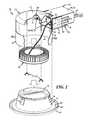
- FIG. 3is a perspective view of the assembly of FIG. 1 with a lamp module of the assembly having been removed downwardly through a lower opening of a lamp housing of the assembly, but remaining connected by electrical wiring to a power supply of the assembly;
- FIG. 4is a partially cut-away perspective view of the assembly of FIG. 1 with the power supply having been removed downwardly through the lower opening of the lamp housing of the assembly and with a back wall of the power supply cut away to reveal an LED driver of the power supply;
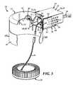
- FIG. 5is a partially cut-away perspective view of the assembly of FIG. 1 with the lamp module having been removed downwardly through the lower opening of the lamp housing, and electrically disconnected from the power supply.
- a downward illumination assembly for directing light downward from the ceiling area of a room, such as an elevator passenger compartment,is generally shown at 10 in FIGS. 1-5 .
- the assembly 10may include a lamp housing 12 , a power supply module 14 comprising an LED driver 16 , a power supply module support surface 18 , and an LED module 20 comprising an LED and carried by the lamp housing 12 .
- the LED module 20may be electrically coupled to the power supply module 14 .
- the power supply module 14may be removably supported in an installed position in which at least a portion of the power supply module 14 is disposed outside the lamp housing 12 .
- the power supply module 14may include a power supply module enclosure 24 including a box portion 26 having a box opening 28 and a cover panel 30 removably securable to close a top portion of the box portion 26 .
- the power supply module enclosure 24may also include ventilation holes 32 .
- the power supply module enclosure 24may include an electrical power port 34 that may be disposed in a radially outer one of two end panels (not shown) of the power supply module enclosure 24 .
- a current path 38may extend from the LED module 20 through the power supply module 14 and the electrical power port 34 and may be connectable to an electrical power source 40 .
- the current path 38may complete an electrical power circuit comprising the LED module 20 , the power supply module 14 , and the electrical power source 40 .
- the lamp housing 12may have a closed upper end 42 , and a housing interior defined by a housing wall 44 extending downwardly to an open lower end 46 from around a periphery of the closed upper end 42 .
- the open lower end 46 of the lamp housing 12may be configured to be positioned adjacent an opening 48 in a ceiling panel 50 .
- the closed housing upper end 42may be generally circular in shape, and the housing wall 44 may be generally cylindrical in shape.
- the upper end and wall of the lamp housing 12may define, or give the housing 12 the shape of, a downwardly opening canister.
- the LED module 20may be removably fastened to the closed upper end 42 of the lamp housing 12 by two LED module fasteners 52 as best shown in FIGS. 1 and 3 .
- Each LED module fastener 52may include a threaded mounting post 54 carried by and extending axially downward from the closed upper end 42 of the lamp housing 12 , and the LED module 20 may include two openings 56 configured and positioned to receive the respective mounting posts 54 .
- Each LED module fastener 52may further include a nut 53 , such as, for example, a wing nut that is configured to thread onto one of the mounting posts 54 and secure the LED module 20 in its installed position.
- the nuts 53may also be configured to unthread from the mounting posts 54 to free the LED module 20 for removal.
- the lamp housing 12may also include a power supply module receptacle opening 56 formed in the housing wall 44 .
- the power supply module receptacle opening 56may be spaced from the open lower end 46 of the housing 12 , and the opening 56 may be shaped, and may be large enough, to allow the power supply module 14 to pass completely through between the installed position and the housing interior.
- the opening 56may be configured to allow the power supply module 14 to be removed interiorly of the lamp housing 12 by drawing the power supply module 14 into the lamp housing 12 through the opening 56 into a position from which the power supply module 14 may then be removed through the open lower end 46 of the lamp housing 12 .
- the assembly 10may include a side-mounted power supply module receptacle tray 58 carried by the housing wall 44 in alignment with the power supply module receptacle opening 56 .
- the power supply module receptacle tray 58may include a floor panel 60 and two side panels 62 extending integrally upward from along opposite side edges 61 of the floor panel 60 .
- the two side panels 62may be spaced to receive the power supply module 14 as it is moved from a position within the lamp housing 12 to the installed position between the side panels 62 on the receptacle tray 58 , and to allow the power supply module 14 to be removed from the installed position on the receptacle tray 58 to a position within the lamp housing 12 .
- the power supply module enclosure cover 30may also be configured to be fastened to the power supply module enclosure box portion 26 without impeding sliding motion of the power supply module 14 along the power supply module receptacle tray 58 .
- the receptacle tray 58may also include the power supply module support surface 18 .
- the power supply module support surface 18may be positioned and configured to support the power supply module 14 as the power supply module 14 is moved between the installed position and the lamp housing interior so that the power supply module 14 can be installed and removed interiorly of the lamp housing 12 through the open lower end 46 of the lamp housing 12 .
- the power supply module 14may be removably supported on the power supply module receptacle tray 58 such that an LED module 20 may fit within the lamp housing 12 when the power supply module 14 is in the installed position.
- the power supply module receptacle tray 58may include tray mounting tabs 64 extending circumferentially outwardly from the side panels 62 of the tray 58 .
- the tray mounting tabs 64may be fastened to the housing wall 44 .
- An inner end of the power supply module 14may include power supply module mounting tabs 66 (best shown in FIG. 4 ) positioned to engage the lamp housing wall 44 adjacent the power supply module receptacle opening 56 .
- the power supply module mounting tabs 66may be positioned to engage power supply module fasteners 68 mounted on an inner surface of the lamp housing wall 44 adjacent the power supply module receptacle opening 56 .
- each power supply module fastener 68may include a threaded mounting post 70 carried by and extending radially inward from the lamp housing wall 44 , and each power supply mounting tab 66 may include an opening 71 configured to receive a threaded post 70 .
- Each power supply module fastener 68may further include a nut 69 , such as, for example, a wing nut, that is configured to thread onto the post 70 and secure a mounting tab 66 to the lamp housing wall 44 , thus securing the power supply module 14 in the installed position.
- the nuts 69may also be configured to unthread from the mounting posts 70 to free the power supply module 14 for removal.
- the trim bezel 72may carry a lens 76 across an upper opening 78 of the bezel, and may include an annular pad 80 within a circumferential trough 81 formed into a lower annular flange 82 of the bezel 72 .
- the annular pad 80is positioned to engage a lower rim 47 of the lamp housing 12 when the trim bezel 72 is installed.
- the power supply module 14 of the downward illumination assembly 10may be removed by first removing the trim bezel 72 from the lamp housing 12 to gain access to the interior of the lamp housing 12 as shown in FIG. 2 .
- the LED module 20may then be removed from its installed position within the lamp housing 12 by first unscrewing the LED module fasteners 52 from the LED module mounting posts 54 and then lowering the LED module 20 through the open lower end 46 of the lamp housing 12 as shown in FIG. 4 .
- the power supply module 14may then be removed from its installed position on the power supply module receptacle tray 58 by disengaging the power supply module fasteners 68 releasably fastening the power supply module mounting tabs 66 to the lamp housing wall 44 , i.e., by unscrewing the wing nuts 69 from the threaded power supply module mounting posts 70 .
- the power supply module 14may then be passed into the lamp housing interior and then out through the open lower end 46 of the lamp housing 12 .
- a power supply module 14may be installed in the assembly 10 by passing the power supply module 14 into the housing interior through the open lower end 46 of the lamp housing 12 and then into its installed position on and extending at least partially outside the lamp housing 12 , then releasably fastening the power supply module 14 to the housing wall 44 by engaging a power supply module fastener 68 .
- a downward illumination assembly constructed as described aboveallows easy removal for repair of replacement of bulky parts of the assembly without any need to access the assembly from above, despite the fact that the assembly extends well beyond the radius of the exposed lower end of its housing.
Landscapes
- Engineering & Computer Science (AREA)
- General Engineering & Computer Science (AREA)
- Power Engineering (AREA)
- Arrangement Of Elements, Cooling, Sealing, Or The Like Of Lighting Devices (AREA)
- Non-Portable Lighting Devices Or Systems Thereof (AREA)
Abstract
Description
Claims (23)
Priority Applications (1)
| Application Number | Priority Date | Filing Date | Title |
|---|---|---|---|
| US14/209,474US9696022B2 (en) | 2013-03-14 | 2014-03-13 | Downward illumination assembly |
Applications Claiming Priority (2)
| Application Number | Priority Date | Filing Date | Title |
|---|---|---|---|
| US201361782052P | 2013-03-14 | 2013-03-14 | |
| US14/209,474US9696022B2 (en) | 2013-03-14 | 2014-03-13 | Downward illumination assembly |
Publications (2)
| Publication Number | Publication Date |
|---|---|
| US20140268829A1 US20140268829A1 (en) | 2014-09-18 |
| US9696022B2true US9696022B2 (en) | 2017-07-04 |
Family
ID=51526342
Family Applications (1)
| Application Number | Title | Priority Date | Filing Date |
|---|---|---|---|
| US14/209,474Active2035-01-16US9696022B2 (en) | 2013-03-14 | 2014-03-13 | Downward illumination assembly |
Country Status (1)
| Country | Link |
|---|---|
| US (1) | US9696022B2 (en) |
Cited By (1)
| Publication number | Priority date | Publication date | Assignee | Title |
|---|---|---|---|---|
| US20170269371A1 (en)* | 2016-03-21 | 2017-09-21 | Hubbell Incorporated | Light fixture with narrow light distribution |
Families Citing this family (9)
| Publication number | Priority date | Publication date | Assignee | Title |
|---|---|---|---|---|
| US9933144B2 (en) | 2013-09-20 | 2018-04-03 | Man-D-Tec, Inc. | Light fixture mounting assembly |
| US9453639B2 (en) | 2013-09-24 | 2016-09-27 | Mandy Holdings Lllp | Rectilinear light source for elevator interior |
| JP2017162768A (en)* | 2016-03-11 | 2017-09-14 | アイリスオーヤマ株式会社 | LED lighting device |
| WO2018150373A1 (en)* | 2017-02-16 | 2018-08-23 | Aurora Limited | Improved downlight |
| US11867384B2 (en)* | 2017-06-19 | 2024-01-09 | Axis Lighting Inc. | Removable positioning of light fixtures |
| US11300276B1 (en) | 2020-09-29 | 2022-04-12 | Axis Lighting Inc. | Luminaire structure |
| US10473307B2 (en) | 2017-06-19 | 2019-11-12 | Axis Lighting Inc. | Removable positioning of light fixtures |
| US11085599B2 (en)* | 2019-06-05 | 2021-08-10 | Ideal Industries Lighting Llc | Overhead light fixtures and methods |
| US11828434B2 (en) | 2019-05-20 | 2023-11-28 | Ideal Industries Lighting Llc | LED light fixtures with waveguide edge |
Citations (105)
| Publication number | Priority date | Publication date | Assignee | Title |
|---|---|---|---|---|
| US1767988A (en) | 1929-01-26 | 1930-06-24 | Otis Elevator Co | Ventilating apparatus |
| US2835791A (en) | 1957-05-09 | 1958-05-20 | Markstone Mfg Company | Recessed lighting fixture assembly |
| US3189788A (en) | 1961-01-03 | 1965-06-15 | Charles A Cady | Power failure responsive circuits |
| US3294977A (en) | 1963-09-24 | 1966-12-27 | Maintenance Company Inc | Emergency power supply unit |
| US3336473A (en) | 1965-09-13 | 1967-08-15 | Art Metal Lighting Division | Lighting fixture with auxiliary lamp |
| US3628852A (en)* | 1970-03-23 | 1971-12-21 | Advanced Patent Technology Inc | Adjustably positionable reflectors |
| US3760179A (en) | 1972-07-24 | 1973-09-18 | C Addington | Indirectly lighted panels for walls and ceilings |
| US3808499A (en) | 1969-03-24 | 1974-04-30 | Nylube Prod Co | Auxiliary lighting system |
| US4013993A (en) | 1976-03-22 | 1977-03-22 | Westinghouse Electric Corporation | Elevator system |
| US4032828A (en) | 1976-04-12 | 1977-06-28 | Korhumel Industries, Inc. | Battery back-up system for electromagnets |
| US4039822A (en) | 1976-05-05 | 1977-08-02 | Lightolier Incorporated | Circular recessed lighting fixture |
| US4056757A (en) | 1972-03-02 | 1977-11-01 | John C. Bogue | Emergency lighting system |
| US4071749A (en) | 1976-07-22 | 1978-01-31 | Tork, Inc. | Self-contained maintenance-free emergency lighting |
| US4156891A (en) | 1976-09-27 | 1979-05-29 | Roche Thomas F | Explosion-proof emergency light |
| US4218725A (en) | 1979-01-15 | 1980-08-19 | Heffner Ronald J | Emergency light |
| US4223232A (en) | 1978-05-31 | 1980-09-16 | Chloride Incorporated | Battery charging circuit for an emergency system |
| US4234907A (en) | 1979-01-29 | 1980-11-18 | Maurice Daniel | Light emitting fabric |
| US4241871A (en) | 1978-11-27 | 1980-12-30 | Newell Alfred T Iii | Apparatus and method for ventilation of animal enclosures |
| US4271621A (en) | 1979-04-06 | 1981-06-09 | Devine Lighting, Incorporated | Conversion unit for electrical light fixture |
| US4441143A (en) | 1980-08-11 | 1984-04-03 | Gladwin, Inc. | Photo voltaic lighting for outdoor telephone booth |
| US4504894A (en) | 1980-11-13 | 1985-03-12 | Whiteway Manufacturing Co. | Lighting unit for providing indirect light |
| US4520436A (en) | 1983-03-25 | 1985-05-28 | Nrg Inc. Mn | Lamp apparatus |
| US4587597A (en) | 1984-11-19 | 1986-05-06 | Meyers Charles J | Emergency exit light or the like |
| US4682078A (en) | 1985-01-28 | 1987-07-21 | Radiant Illumination, Inc. | Wireless emergency lighting unit |
| US4697890A (en) | 1985-10-03 | 1987-10-06 | Crookston Byron F | Light emitting device |
| US4708223A (en) | 1986-09-29 | 1987-11-24 | Westinghouse Electric Corp. | Emergency lighting for elevator cab |
| US4727291A (en) | 1985-10-15 | 1988-02-23 | Bavco Manufacturing Co. | Back-up electrical system for lamps |
| US4749908A (en) | 1985-12-26 | 1988-06-07 | Electronic Specialists, Inc. | Emergency power supply |
| US4751398A (en) | 1986-03-18 | 1988-06-14 | The Bodine Company | Lighting system for normal and emergency operation of high intensity discharge lamps |
| US4802065A (en) | 1987-08-27 | 1989-01-31 | Minter Ronald H | Emergency lighting fixture |
| US4875553A (en) | 1986-07-29 | 1989-10-24 | Montgomery Elevator Company | Modular elevator cab construction |
| US4885663A (en) | 1988-03-22 | 1989-12-05 | Lumitex, Inc. | Fiber optic light emitting panel and method of making same |
| US4890200A (en) | 1988-05-09 | 1989-12-26 | Mandy Robert R | Down lighting systems and fixtures therefor |
| US4905579A (en) | 1988-03-11 | 1990-03-06 | Dame Richard E | Radon gas ventilation pump system and method |
| US4907132A (en) | 1988-03-22 | 1990-03-06 | Lumitex, Inc. | Light emitting panel assemblies and method of making same |
| US4947291A (en) | 1988-06-17 | 1990-08-07 | Mcdermott Kevin | Lighting device |
| US4977818A (en) | 1988-07-22 | 1990-12-18 | Taylor Harry L | Air flow control system |
| US5003432A (en) | 1988-05-09 | 1991-03-26 | Mandy Robert R | Down lighting systems and fixtures therefor |
| US5005108A (en) | 1989-02-10 | 1991-04-02 | Lumitex, Inc. | Thin panel illuminator |
| US5021928A (en) | 1982-09-29 | 1991-06-04 | Maurice Daniel | Flat panel illumination system |
| US5025349A (en) | 1988-09-08 | 1991-06-18 | Gow Thomas W | Emergency lighting fixture |
| US5123875A (en) | 1991-04-12 | 1992-06-23 | Eubank Manufacturing Enterprises, Inc. | Power actuated roof vent apparatus and method of use |
| EP0495273A1 (en) | 1991-01-16 | 1992-07-22 | Lumitex Inc. | Thin panel illuminator |
| US5145247A (en) | 1991-03-20 | 1992-09-08 | Mandy Robert R | Down lighting systems and fixtures therefor |
| US5161879A (en) | 1991-04-10 | 1992-11-10 | Mcdermott Kevin | Flashlight for covert applications |
| US5253152A (en) | 1991-08-12 | 1993-10-12 | Yang Thien S | Lightweight plug-in fluorescent lamp assembly |
| US5408394A (en) | 1988-05-09 | 1995-04-18 | Man-D-Tec, Inc. | Down lighting systems and fixtures thereof |
| US5412542A (en) | 1991-03-20 | 1995-05-02 | Man-D-Tec, Inc. | Down lighting systems and fixtures therefor |
| US5568964A (en) | 1992-07-10 | 1996-10-29 | Lumitex, Inc. | Fiber optic light emitting panel assemblies and methods of making such panel assemblies |
| US5613751A (en) | 1995-06-27 | 1997-03-25 | Lumitex, Inc. | Light emitting panel assemblies |
| US5661645A (en) | 1996-06-27 | 1997-08-26 | Hochstein; Peter A. | Power supply for light emitting diode array |
| US5664872A (en)* | 1993-11-23 | 1997-09-09 | Smiths Industries Plc | Combined lamp and fan assembly |
| US5739639A (en) | 1996-07-03 | 1998-04-14 | Nsi Enterprises, Inc. | Method and apparatus for operating LED array and charging battery for emergency LED operation including DC boost circuit allowing series connection of LED array and battery |
| US5850126A (en) | 1997-04-11 | 1998-12-15 | Kanbar; Maurice S. | Screw-in led lamp |
| US5895115A (en) | 1996-01-16 | 1999-04-20 | Lumitex, Inc. | Light emitting panel assemblies for use in automotive applications and the like |
| US5894686A (en) | 1993-11-04 | 1999-04-20 | Lumitex, Inc. | Light distribution/information display systems |
| US5921670A (en) | 1996-03-15 | 1999-07-13 | Daimler-Benz Aerospace Airbus Gmbh | Lighting system for a passenger cabin especially in an aircraft |
| US5966069A (en) | 1998-03-19 | 1999-10-12 | Prescolite-Moldcast Lighting Company | Exit sign self-testing system |
| US6185356B1 (en) | 1995-06-27 | 2001-02-06 | Lumitex, Inc. | Protective cover for a lighting device |
| WO2003019073A1 (en) | 2001-08-23 | 2003-03-06 | Lumitex, Inc. | Light delivery systems and applications thereof |
| US6609804B2 (en) | 2001-10-15 | 2003-08-26 | Steven T. Nolan | LED interior light fixture |
| US6712481B2 (en) | 1995-06-27 | 2004-03-30 | Solid State Opto Limited | Light emitting panel assemblies |
| US6752505B2 (en) | 1999-02-23 | 2004-06-22 | Solid State Opto Limited | Light redirecting films and film systems |
| US20040125246A1 (en) | 2002-09-30 | 2004-07-01 | Shinji Okamori | Projection-type display apparatus |
| US6764196B2 (en) | 2001-03-29 | 2004-07-20 | Bendrix B. Bailey | Lighting system |
| US6827456B2 (en) | 1999-02-23 | 2004-12-07 | Solid State Opto Limited | Transreflectors, transreflector systems and displays and methods of making transreflectors |
| US6860628B2 (en) | 2002-07-17 | 2005-03-01 | Jonas J. Robertson | LED replacement for fluorescent lighting |
| US6872220B2 (en) | 2003-01-16 | 2005-03-29 | Lumitex, Inc. | Infant phototherapy positioning system |
| US6874925B2 (en) | 2003-03-06 | 2005-04-05 | Lumitex, Inc. | Fiber optic light panel assemblies and method of manufacture |
| US20050190345A1 (en) | 2004-02-27 | 2005-09-01 | Dubin Matthew B. | Electro-optical dimming system |
| WO2005098806A1 (en) | 2004-04-08 | 2005-10-20 | Stmicroelectronics S.R.L. | Driver for an oled passive-matrix display |
| US6994457B2 (en) | 2003-08-13 | 2006-02-07 | Jji Lighting Group, Inc. | Recessed downlight lighting apparatus |
| US20060038192A1 (en) | 2004-08-17 | 2006-02-23 | Williams Jeffrey B | Fiber optic phototherapy devices including LED light sources |
| US7066617B2 (en) | 2002-09-12 | 2006-06-27 | Man-D-Tec | Downward illumination assembly |
| US7071625B2 (en) | 2003-04-08 | 2006-07-04 | Hsin-Hui Cheng | LED illuminator with capability of stable brightness |
| US20060187654A1 (en) | 2003-07-24 | 2006-08-24 | Johannes Jungel-Schmid | Ambient lighting system |
| US7114829B2 (en) | 2004-12-01 | 2006-10-03 | Wen-Cheng Lai | Multi-facet full color illuminator |
| US7246926B2 (en) | 2004-05-11 | 2007-07-24 | Harwood Ronald P | Color changing light fixture |
| US20070195532A1 (en) | 2006-02-21 | 2007-08-23 | Cml Innovative Technologies, Inc. | LED lamp module |
| US7261453B2 (en) | 2005-01-25 | 2007-08-28 | Morejon Israel J | LED polarizing optics for color illumination system and method of using same |
| US20070242461A1 (en) | 2006-04-12 | 2007-10-18 | Cml Innovative Technologies, Inc. | LED based light engine |
| US20080024010A1 (en) | 2006-07-31 | 2008-01-31 | John Romano | Automatic auxiliary lighting unit |
| US20080084700A1 (en) | 2006-09-18 | 2008-04-10 | Led Lighting Fixtures, Inc. | Lighting devices, lighting assemblies, fixtures and method of using same |
| US7396139B2 (en) | 2004-05-07 | 2008-07-08 | Savage Nigel C | Underwater lighting apparatus |
| US20080192489A1 (en) | 2007-02-12 | 2008-08-14 | Lucifer Lighting Co. | PUK LED light fixture |
| US20080258628A1 (en) | 2007-04-17 | 2008-10-23 | Cree, Inc. | Light Emitting Diode Emergency Lighting Methods and Apparatus |
| US20080285271A1 (en)* | 2007-05-04 | 2008-11-20 | Philips Solid-State Lighting Solutions, Inc. | Led-based fixtures and related methods for thermal management |
| US20080296975A1 (en) | 2007-06-04 | 2008-12-04 | Walter Jeffrey Shakespeare | Back-up power system |
| US7486033B2 (en) | 2006-10-26 | 2009-02-03 | Industrial Technology Research Institute | Lighting device |
| US7484863B1 (en)* | 2006-11-16 | 2009-02-03 | Truman Aubrey | Lighting fixture |
| US20090080189A1 (en)* | 2007-09-21 | 2009-03-26 | Cooper Technologies Company | Optic Coupler for Light Emitting Diode Fixture |
| US20090290361A1 (en) | 2008-05-23 | 2009-11-26 | Ruud Lighting, Inc. | Recessed LED Lighting Fixture |
| US7722227B2 (en)* | 2007-10-10 | 2010-05-25 | Cordelia Lighting, Inc. | Lighting fixture with recessed baffle trim unit |
| US20110044047A1 (en) | 2008-09-10 | 2011-02-24 | Man-D-Tec | Method of Equalizing Light Levels Between LED Light Fixtures |
| US7896517B2 (en)* | 2008-04-29 | 2011-03-01 | Man-D-Tec, Inc. | Downward illumination assembly |
| US20110216547A1 (en)* | 2010-03-05 | 2011-09-08 | Toshiba Lighting & Technology Corporation | Lighting apparatus |
| US20110222291A1 (en)* | 2010-03-15 | 2011-09-15 | Chunghang Peng | Lighting fixture with integrated junction-box |
| US20110299290A1 (en) | 2010-06-08 | 2011-12-08 | Man-D-Tec | Light fixture mounting method and assembly |
| US20120140490A1 (en)* | 2010-12-03 | 2012-06-07 | Cree, Inc. | Heat transfer bracket for lighting fixture |
| US8220970B1 (en)* | 2009-02-11 | 2012-07-17 | Koninklijke Philips Electronics N.V. | Heat dissipation assembly for an LED downlight |
| US20120182744A1 (en)* | 2011-01-14 | 2012-07-19 | Cordelia Lighting, Inc. | Led universal recessed light fixture |
| US20120187852A1 (en) | 2011-01-25 | 2012-07-26 | Man-D-Tec, Inc. | Elevator Emergency LED Lighting Power Supply Assembly |
| US20130033872A1 (en)* | 2010-11-15 | 2013-02-07 | Cree, Inc. | Lighting fixture |
| US20130201679A1 (en)* | 2012-02-03 | 2013-08-08 | Cree, Inc. | Lighting device and method of installing light emitter |
| US9004713B2 (en) | 2008-09-10 | 2015-04-14 | Man-D-Tec, Inc. | Illumination assembly |
- 2014
- 2014-03-13USUS14/209,474patent/US9696022B2/enactiveActive
Patent Citations (117)
| Publication number | Priority date | Publication date | Assignee | Title |
|---|---|---|---|---|
| US1767988A (en) | 1929-01-26 | 1930-06-24 | Otis Elevator Co | Ventilating apparatus |
| US2835791A (en) | 1957-05-09 | 1958-05-20 | Markstone Mfg Company | Recessed lighting fixture assembly |
| US3189788A (en) | 1961-01-03 | 1965-06-15 | Charles A Cady | Power failure responsive circuits |
| US3294977A (en) | 1963-09-24 | 1966-12-27 | Maintenance Company Inc | Emergency power supply unit |
| US3336473A (en) | 1965-09-13 | 1967-08-15 | Art Metal Lighting Division | Lighting fixture with auxiliary lamp |
| US3808499A (en) | 1969-03-24 | 1974-04-30 | Nylube Prod Co | Auxiliary lighting system |
| US3628852A (en)* | 1970-03-23 | 1971-12-21 | Advanced Patent Technology Inc | Adjustably positionable reflectors |
| US4056757A (en) | 1972-03-02 | 1977-11-01 | John C. Bogue | Emergency lighting system |
| US3760179A (en) | 1972-07-24 | 1973-09-18 | C Addington | Indirectly lighted panels for walls and ceilings |
| US4013993A (en) | 1976-03-22 | 1977-03-22 | Westinghouse Electric Corporation | Elevator system |
| US4032828A (en) | 1976-04-12 | 1977-06-28 | Korhumel Industries, Inc. | Battery back-up system for electromagnets |
| US4039822A (en) | 1976-05-05 | 1977-08-02 | Lightolier Incorporated | Circular recessed lighting fixture |
| US4071749A (en) | 1976-07-22 | 1978-01-31 | Tork, Inc. | Self-contained maintenance-free emergency lighting |
| US4156891A (en) | 1976-09-27 | 1979-05-29 | Roche Thomas F | Explosion-proof emergency light |
| US4223232A (en) | 1978-05-31 | 1980-09-16 | Chloride Incorporated | Battery charging circuit for an emergency system |
| US4241871A (en) | 1978-11-27 | 1980-12-30 | Newell Alfred T Iii | Apparatus and method for ventilation of animal enclosures |
| US4218725A (en) | 1979-01-15 | 1980-08-19 | Heffner Ronald J | Emergency light |
| US4234907A (en) | 1979-01-29 | 1980-11-18 | Maurice Daniel | Light emitting fabric |
| US4271621A (en) | 1979-04-06 | 1981-06-09 | Devine Lighting, Incorporated | Conversion unit for electrical light fixture |
| US4441143A (en) | 1980-08-11 | 1984-04-03 | Gladwin, Inc. | Photo voltaic lighting for outdoor telephone booth |
| US4504894A (en) | 1980-11-13 | 1985-03-12 | Whiteway Manufacturing Co. | Lighting unit for providing indirect light |
| US5021928A (en) | 1982-09-29 | 1991-06-04 | Maurice Daniel | Flat panel illumination system |
| US4520436A (en) | 1983-03-25 | 1985-05-28 | Nrg Inc. Mn | Lamp apparatus |
| US4587597A (en) | 1984-11-19 | 1986-05-06 | Meyers Charles J | Emergency exit light or the like |
| US4682078A (en) | 1985-01-28 | 1987-07-21 | Radiant Illumination, Inc. | Wireless emergency lighting unit |
| US4697890A (en) | 1985-10-03 | 1987-10-06 | Crookston Byron F | Light emitting device |
| US4727291A (en) | 1985-10-15 | 1988-02-23 | Bavco Manufacturing Co. | Back-up electrical system for lamps |
| US4749908A (en) | 1985-12-26 | 1988-06-07 | Electronic Specialists, Inc. | Emergency power supply |
| US4751398A (en) | 1986-03-18 | 1988-06-14 | The Bodine Company | Lighting system for normal and emergency operation of high intensity discharge lamps |
| US4875553A (en) | 1986-07-29 | 1989-10-24 | Montgomery Elevator Company | Modular elevator cab construction |
| US4708223A (en) | 1986-09-29 | 1987-11-24 | Westinghouse Electric Corp. | Emergency lighting for elevator cab |
| US4802065A (en) | 1987-08-27 | 1989-01-31 | Minter Ronald H | Emergency lighting fixture |
| US4905579A (en) | 1988-03-11 | 1990-03-06 | Dame Richard E | Radon gas ventilation pump system and method |
| US4885663A (en) | 1988-03-22 | 1989-12-05 | Lumitex, Inc. | Fiber optic light emitting panel and method of making same |
| US4907132A (en) | 1988-03-22 | 1990-03-06 | Lumitex, Inc. | Light emitting panel assemblies and method of making same |
| US5408394A (en) | 1988-05-09 | 1995-04-18 | Man-D-Tec, Inc. | Down lighting systems and fixtures thereof |
| US5003432A (en) | 1988-05-09 | 1991-03-26 | Mandy Robert R | Down lighting systems and fixtures therefor |
| US4890200A (en) | 1988-05-09 | 1989-12-26 | Mandy Robert R | Down lighting systems and fixtures therefor |
| US4947291A (en) | 1988-06-17 | 1990-08-07 | Mcdermott Kevin | Lighting device |
| US4977818A (en) | 1988-07-22 | 1990-12-18 | Taylor Harry L | Air flow control system |
| US5025349A (en) | 1988-09-08 | 1991-06-18 | Gow Thomas W | Emergency lighting fixture |
| US5005108A (en) | 1989-02-10 | 1991-04-02 | Lumitex, Inc. | Thin panel illuminator |
| EP0495273A1 (en) | 1991-01-16 | 1992-07-22 | Lumitex Inc. | Thin panel illuminator |
| US5412542A (en) | 1991-03-20 | 1995-05-02 | Man-D-Tec, Inc. | Down lighting systems and fixtures therefor |
| US5145247A (en) | 1991-03-20 | 1992-09-08 | Mandy Robert R | Down lighting systems and fixtures therefor |
| US5161879A (en) | 1991-04-10 | 1992-11-10 | Mcdermott Kevin | Flashlight for covert applications |
| US5123875A (en) | 1991-04-12 | 1992-06-23 | Eubank Manufacturing Enterprises, Inc. | Power actuated roof vent apparatus and method of use |
| US5253152A (en) | 1991-08-12 | 1993-10-12 | Yang Thien S | Lightweight plug-in fluorescent lamp assembly |
| US5568964A (en) | 1992-07-10 | 1996-10-29 | Lumitex, Inc. | Fiber optic light emitting panel assemblies and methods of making such panel assemblies |
| US6030089A (en) | 1993-11-04 | 2000-02-29 | Lumitex, Inc. | Light distribution system including an area light emitting portion contained in a flexible holder |
| US5894686A (en) | 1993-11-04 | 1999-04-20 | Lumitex, Inc. | Light distribution/information display systems |
| US5664872A (en)* | 1993-11-23 | 1997-09-09 | Smiths Industries Plc | Combined lamp and fan assembly |
| US5921652A (en) | 1995-06-27 | 1999-07-13 | Lumitex, Inc. | Light emitting panel assemblies |
| US6712481B2 (en) | 1995-06-27 | 2004-03-30 | Solid State Opto Limited | Light emitting panel assemblies |
| US5876107A (en) | 1995-06-27 | 1999-03-02 | Lumitex, Inc. | Light emitting panel assemblies |
| US5618096A (en) | 1995-06-27 | 1997-04-08 | Lumitex, Inc. | Light emitting panel assemblies |
| US5613751A (en) | 1995-06-27 | 1997-03-25 | Lumitex, Inc. | Light emitting panel assemblies |
| US6079838A (en) | 1995-06-27 | 2000-06-27 | Lumitex, Inc. | Light emitting panel assemblies |
| US6185356B1 (en) | 1995-06-27 | 2001-02-06 | Lumitex, Inc. | Protective cover for a lighting device |
| US5895115A (en) | 1996-01-16 | 1999-04-20 | Lumitex, Inc. | Light emitting panel assemblies for use in automotive applications and the like |
| US6158867A (en) | 1996-01-16 | 2000-12-12 | Lumitex, Inc. | Light emitting panel assemblies for use in automotive applications and the like |
| US5921670A (en) | 1996-03-15 | 1999-07-13 | Daimler-Benz Aerospace Airbus Gmbh | Lighting system for a passenger cabin especially in an aircraft |
| US5661645A (en) | 1996-06-27 | 1997-08-26 | Hochstein; Peter A. | Power supply for light emitting diode array |
| US5739639A (en) | 1996-07-03 | 1998-04-14 | Nsi Enterprises, Inc. | Method and apparatus for operating LED array and charging battery for emergency LED operation including DC boost circuit allowing series connection of LED array and battery |
| US5850126A (en) | 1997-04-11 | 1998-12-15 | Kanbar; Maurice S. | Screw-in led lamp |
| US5966069A (en) | 1998-03-19 | 1999-10-12 | Prescolite-Moldcast Lighting Company | Exit sign self-testing system |
| US6752505B2 (en) | 1999-02-23 | 2004-06-22 | Solid State Opto Limited | Light redirecting films and film systems |
| US6827456B2 (en) | 1999-02-23 | 2004-12-07 | Solid State Opto Limited | Transreflectors, transreflector systems and displays and methods of making transreflectors |
| US7077544B2 (en) | 1999-02-23 | 2006-07-18 | Solid State Opto Limited | Light emitting panel assemblies |
| US6764196B2 (en) | 2001-03-29 | 2004-07-20 | Bendrix B. Bailey | Lighting system |
| WO2003019073A1 (en) | 2001-08-23 | 2003-03-06 | Lumitex, Inc. | Light delivery systems and applications thereof |
| US6609804B2 (en) | 2001-10-15 | 2003-08-26 | Steven T. Nolan | LED interior light fixture |
| US7114830B2 (en) | 2002-07-17 | 2006-10-03 | Plastic Inventions And Patents, Inc. | LED replacement for fluorescent lighting |
| US6860628B2 (en) | 2002-07-17 | 2005-03-01 | Jonas J. Robertson | LED replacement for fluorescent lighting |
| US7066617B2 (en) | 2002-09-12 | 2006-06-27 | Man-D-Tec | Downward illumination assembly |
| US20040125246A1 (en) | 2002-09-30 | 2004-07-01 | Shinji Okamori | Projection-type display apparatus |
| US6872220B2 (en) | 2003-01-16 | 2005-03-29 | Lumitex, Inc. | Infant phototherapy positioning system |
| US6874925B2 (en) | 2003-03-06 | 2005-04-05 | Lumitex, Inc. | Fiber optic light panel assemblies and method of manufacture |
| US7071625B2 (en) | 2003-04-08 | 2006-07-04 | Hsin-Hui Cheng | LED illuminator with capability of stable brightness |
| US20060187654A1 (en) | 2003-07-24 | 2006-08-24 | Johannes Jungel-Schmid | Ambient lighting system |
| US6994457B2 (en) | 2003-08-13 | 2006-02-07 | Jji Lighting Group, Inc. | Recessed downlight lighting apparatus |
| US20050190345A1 (en) | 2004-02-27 | 2005-09-01 | Dubin Matthew B. | Electro-optical dimming system |
| WO2005098806A1 (en) | 2004-04-08 | 2005-10-20 | Stmicroelectronics S.R.L. | Driver for an oled passive-matrix display |
| US7396139B2 (en) | 2004-05-07 | 2008-07-08 | Savage Nigel C | Underwater lighting apparatus |
| US7246926B2 (en) | 2004-05-11 | 2007-07-24 | Harwood Ronald P | Color changing light fixture |
| US20060038192A1 (en) | 2004-08-17 | 2006-02-23 | Williams Jeffrey B | Fiber optic phototherapy devices including LED light sources |
| WO2006031350A2 (en) | 2004-08-17 | 2006-03-23 | Lumitex, Inc. | Fiber optic phototherapy devices including led light sources |
| US7114829B2 (en) | 2004-12-01 | 2006-10-03 | Wen-Cheng Lai | Multi-facet full color illuminator |
| US7261453B2 (en) | 2005-01-25 | 2007-08-28 | Morejon Israel J | LED polarizing optics for color illumination system and method of using same |
| US20070195532A1 (en) | 2006-02-21 | 2007-08-23 | Cml Innovative Technologies, Inc. | LED lamp module |
| US20070242461A1 (en) | 2006-04-12 | 2007-10-18 | Cml Innovative Technologies, Inc. | LED based light engine |
| US20080024010A1 (en) | 2006-07-31 | 2008-01-31 | John Romano | Automatic auxiliary lighting unit |
| US20080084700A1 (en) | 2006-09-18 | 2008-04-10 | Led Lighting Fixtures, Inc. | Lighting devices, lighting assemblies, fixtures and method of using same |
| US7486033B2 (en) | 2006-10-26 | 2009-02-03 | Industrial Technology Research Institute | Lighting device |
| US7484863B1 (en)* | 2006-11-16 | 2009-02-03 | Truman Aubrey | Lighting fixture |
| US20080192489A1 (en) | 2007-02-12 | 2008-08-14 | Lucifer Lighting Co. | PUK LED light fixture |
| US20080258628A1 (en) | 2007-04-17 | 2008-10-23 | Cree, Inc. | Light Emitting Diode Emergency Lighting Methods and Apparatus |
| US20080285271A1 (en)* | 2007-05-04 | 2008-11-20 | Philips Solid-State Lighting Solutions, Inc. | Led-based fixtures and related methods for thermal management |
| US20080296975A1 (en) | 2007-06-04 | 2008-12-04 | Walter Jeffrey Shakespeare | Back-up power system |
| US20090080189A1 (en)* | 2007-09-21 | 2009-03-26 | Cooper Technologies Company | Optic Coupler for Light Emitting Diode Fixture |
| US7722227B2 (en)* | 2007-10-10 | 2010-05-25 | Cordelia Lighting, Inc. | Lighting fixture with recessed baffle trim unit |
| US7896517B2 (en)* | 2008-04-29 | 2011-03-01 | Man-D-Tec, Inc. | Downward illumination assembly |
| US20090290361A1 (en) | 2008-05-23 | 2009-11-26 | Ruud Lighting, Inc. | Recessed LED Lighting Fixture |
| US20110044047A1 (en) | 2008-09-10 | 2011-02-24 | Man-D-Tec | Method of Equalizing Light Levels Between LED Light Fixtures |
| US8092035B2 (en) | 2008-09-10 | 2012-01-10 | Man-D-Tec | Illumination method and assembly |
| US8096672B2 (en) | 2008-09-10 | 2012-01-17 | Man-D-Tec, Inc. | Method of equalizing light levels between LED light fixtures |
| US9004713B2 (en) | 2008-09-10 | 2015-04-14 | Man-D-Tec, Inc. | Illumination assembly |
| US8220970B1 (en)* | 2009-02-11 | 2012-07-17 | Koninklijke Philips Electronics N.V. | Heat dissipation assembly for an LED downlight |
| US20110216547A1 (en)* | 2010-03-05 | 2011-09-08 | Toshiba Lighting & Technology Corporation | Lighting apparatus |
| US20110222291A1 (en)* | 2010-03-15 | 2011-09-15 | Chunghang Peng | Lighting fixture with integrated junction-box |
| US20110299290A1 (en) | 2010-06-08 | 2011-12-08 | Man-D-Tec | Light fixture mounting method and assembly |
| US20130033872A1 (en)* | 2010-11-15 | 2013-02-07 | Cree, Inc. | Lighting fixture |
| US20120140490A1 (en)* | 2010-12-03 | 2012-06-07 | Cree, Inc. | Heat transfer bracket for lighting fixture |
| US20120182744A1 (en)* | 2011-01-14 | 2012-07-19 | Cordelia Lighting, Inc. | Led universal recessed light fixture |
| US20120187852A1 (en) | 2011-01-25 | 2012-07-26 | Man-D-Tec, Inc. | Elevator Emergency LED Lighting Power Supply Assembly |
| US8558407B2 (en) | 2011-01-25 | 2013-10-15 | Man-D-Tec, Inc. | Elevator emergency LED lighting power supply assembly |
| US20130201679A1 (en)* | 2012-02-03 | 2013-08-08 | Cree, Inc. | Lighting device and method of installing light emitter |
Non-Patent Citations (2)
| Title |
|---|
| Installation guide for IP110-F Flush Mount Adapter, Pelco, Inc., Dec. 2008, C2238M, 8 pages. |
| Search Report from the Intellectual Property Office for German Application No. GB1204033.3, dated Jun. 14, 2012; 1 page. |
Cited By (3)
| Publication number | Priority date | Publication date | Assignee | Title |
|---|---|---|---|---|
| US20170269371A1 (en)* | 2016-03-21 | 2017-09-21 | Hubbell Incorporated | Light fixture with narrow light distribution |
| US10502375B2 (en)* | 2016-03-21 | 2019-12-10 | Hubbell Incorporated | Light fixture with narrow light distribution |
| US11268666B2 (en) | 2016-03-21 | 2022-03-08 | Hubbell Incorporated | Light fixture with narrow light distribution |
Also Published As
| Publication number | Publication date |
|---|---|
| US20140268829A1 (en) | 2014-09-18 |
Similar Documents
| Publication | Publication Date | Title |
|---|---|---|
| US9696022B2 (en) | Downward illumination assembly | |
| US7896517B2 (en) | Downward illumination assembly | |
| US7066617B2 (en) | Downward illumination assembly | |
| CA2789418C (en) | Lighting apparatus and connector plate | |
| US9169983B2 (en) | Overhead light fixture and related method | |
| CA2560566C (en) | Lighting fixture service access | |
| US5662407A (en) | Canopy luminaire | |
| US9200784B2 (en) | Downward illumination assembly | |
| US11313525B2 (en) | Multi-function lighting fixture | |
| US20140268825A1 (en) | System and Method for Mounting and Locking a Lighting Apparatus | |
| US20100329885A1 (en) | Ceiling fan | |
| US6896423B2 (en) | Camera mounting enclosure and method of installation | |
| GB2509772A (en) | LED down light | |
| US8882308B2 (en) | Recessed LED downlighting apparatus | |
| JP2013539194A (en) | Lighting fixture with lifting device | |
| US8358516B2 (en) | Method and apparatus for mounting a power converter | |
| US20180219322A1 (en) | Covering | |
| US20080084698A1 (en) | Retrofit Canopy Luminaire and Installation Method | |
| US20110088247A1 (en) | Mounting bracket and method | |
| BE1028963B1 (en) | METAL BUILT-IN BOX FOR INSTALLATION OF A LIGHT LUMINAIRES, KIT AND USE OF THE KIT | |
| KR101806869B1 (en) | Ceiling lights | |
| US20200200342A1 (en) | Systems and methods for retrofitting light fixtures | |
| US11415337B2 (en) | Hinged control box for an RVAC | |
| US10168034B2 (en) | Downlight | |
| US20190111948A1 (en) | Ceiling module for a vehicle |
Legal Events
| Date | Code | Title | Description |
|---|---|---|---|
| AS | Assignment | Owner name:MANDY HOLDINGS LLP, ARIZONA Free format text:ASSIGNMENT OF ASSIGNORS INTEREST;ASSIGNORS:MANDY, DALTON J.;MANDY, TERRY R.;MANDY, BRANDON R.;REEL/FRAME:035733/0654 Effective date:20150421 | |
| AS | Assignment | Owner name:MANDY HOLDINGS LLLP, ARIZONA Free format text:CORRECTIVE ASSIGNMENT TO CORRECT THE CORRECTION TO THE SPELLING OF ASSIGNEE'S NAME WHICH SHOULD BE MANDY HOLDINGS LLLP PREVIOUSLY RECORDED ON REEL 035733 FRAME 0654. ASSIGNOR(S) HEREBY CONFIRMS THE SPELLING OF ASSIGNEE'S NAME AS RECORDED, MANDY HOLDINGS LLP, AT REEL/FRAME 035733/0654 ON DOCUMENT 503325639 IS INCORRECT;ASSIGNORS:MANDY, DALTON J.;MANDY, TERRY R.;MANDY, BRANDON R.;REEL/FRAME:035820/0783 Effective date:20150421 | |
| STCF | Information on status: patent grant | Free format text:PATENTED CASE | |
| AS | Assignment | Owner name:MAN-D-TEC, INC., ARIZONA Free format text:ASSIGNMENT OF ASSIGNORS INTEREST;ASSIGNOR:MANDY HOLDINGS, LLLP;REEL/FRAME:043288/0762 Effective date:20170814 | |
| CC | Certificate of correction | ||
| MAFP | Maintenance fee payment | Free format text:PAYMENT OF MAINTENANCE FEE, 4TH YR, SMALL ENTITY (ORIGINAL EVENT CODE: M2551); ENTITY STATUS OF PATENT OWNER: SMALL ENTITY Year of fee payment:4 | |
| MAFP | Maintenance fee payment | Free format text:PAYMENT OF MAINTENANCE FEE, 8TH YR, SMALL ENTITY (ORIGINAL EVENT CODE: M2552); ENTITY STATUS OF PATENT OWNER: SMALL ENTITY Year of fee payment:8 |