US9695778B2 - Tandem thrust reverser with multi-point actuation - Google Patents
Tandem thrust reverser with multi-point actuationDownload PDFInfo
- Publication number
- US9695778B2 US9695778B2US14/184,398US201414184398AUS9695778B2US 9695778 B2US9695778 B2US 9695778B2US 201414184398 AUS201414184398 AUS 201414184398AUS 9695778 B2US9695778 B2US 9695778B2
- Authority
- US
- United States
- Prior art keywords
- pivot
- tandem
- door subassembly
- actuator
- pivot door
- Prior art date
- Legal status (The legal status is an assumption and is not a legal conclusion. Google has not performed a legal analysis and makes no representation as to the accuracy of the status listed.)
- Active, expires
Links
- 238000009423ventilationMethods0.000claimsdescription5
- 239000007789gasSubstances0.000description18
- 238000013461designMethods0.000description9
- 238000000034methodMethods0.000description5
- 230000000712assemblyEffects0.000description4
- 238000000429assemblyMethods0.000description4
- 238000002955isolationMethods0.000description4
- 238000012423maintenanceMethods0.000description2
- 238000012986modificationMethods0.000description2
- 230000004048modificationEffects0.000description2
- 238000013519translationMethods0.000description2
- 238000011144upstream manufacturingMethods0.000description2
- 239000000567combustion gasSubstances0.000description1
- 230000007423decreaseEffects0.000description1
- 238000004519manufacturing processMethods0.000description1
- 239000000463materialSubstances0.000description1
- 230000013011matingEffects0.000description1
- 230000007246mechanismEffects0.000description1
- 230000001141propulsive effectEffects0.000description1
- 238000007789sealingMethods0.000description1
Images


Classifications
- F—MECHANICAL ENGINEERING; LIGHTING; HEATING; WEAPONS; BLASTING
- F02—COMBUSTION ENGINES; HOT-GAS OR COMBUSTION-PRODUCT ENGINE PLANTS
- F02K—JET-PROPULSION PLANTS
- F02K1/00—Plants characterised by the form or arrangement of the jet pipe or nozzle; Jet pipes or nozzles peculiar thereto
- F02K1/54—Nozzles having means for reversing jet thrust
- F02K1/64—Reversing fan flow
- F02K1/70—Reversing fan flow using thrust reverser flaps or doors mounted on the fan housing
- F02K1/72—Reversing fan flow using thrust reverser flaps or doors mounted on the fan housing the aft end of the fan housing being movable to uncover openings in the fan housing for the reversed flow
- B—PERFORMING OPERATIONS; TRANSPORTING
- B23—MACHINE TOOLS; METAL-WORKING NOT OTHERWISE PROVIDED FOR
- B23P—METAL-WORKING NOT OTHERWISE PROVIDED FOR; COMBINED OPERATIONS; UNIVERSAL MACHINE TOOLS
- B23P19/00—Machines for simply fitting together or separating metal parts or objects, or metal and non-metal parts, whether or not involving some deformation; Tools or devices therefor so far as not provided for in other classes
- B23P19/04—Machines for simply fitting together or separating metal parts or objects, or metal and non-metal parts, whether or not involving some deformation; Tools or devices therefor so far as not provided for in other classes for assembling or disassembling parts
- B—PERFORMING OPERATIONS; TRANSPORTING
- B64—AIRCRAFT; AVIATION; COSMONAUTICS
- B64D—EQUIPMENT FOR FITTING IN OR TO AIRCRAFT; FLIGHT SUITS; PARACHUTES; ARRANGEMENT OR MOUNTING OF POWER PLANTS OR PROPULSION TRANSMISSIONS IN AIRCRAFT
- B64D29/00—Power-plant nacelles, fairings or cowlings
- B—PERFORMING OPERATIONS; TRANSPORTING
- B64—AIRCRAFT; AVIATION; COSMONAUTICS
- B64D—EQUIPMENT FOR FITTING IN OR TO AIRCRAFT; FLIGHT SUITS; PARACHUTES; ARRANGEMENT OR MOUNTING OF POWER PLANTS OR PROPULSION TRANSMISSIONS IN AIRCRAFT
- B64D33/00—Arrangement in aircraft of power plant parts or auxiliaries not otherwise provided for
- B64D33/04—Arrangement in aircraft of power plant parts or auxiliaries not otherwise provided for of exhaust outlets or jet pipes
- F—MECHANICAL ENGINEERING; LIGHTING; HEATING; WEAPONS; BLASTING
- F02—COMBUSTION ENGINES; HOT-GAS OR COMBUSTION-PRODUCT ENGINE PLANTS
- F02K—JET-PROPULSION PLANTS
- F02K1/00—Plants characterised by the form or arrangement of the jet pipe or nozzle; Jet pipes or nozzles peculiar thereto
- F02K1/54—Nozzles having means for reversing jet thrust
- F02K1/56—Reversing jet main flow
- F02K1/60—Reversing jet main flow by blocking the rearward discharge by means of pivoted eyelids or clamshells, e.g. target-type reversers
- F02K1/605—Reversing jet main flow by blocking the rearward discharge by means of pivoted eyelids or clamshells, e.g. target-type reversers the aft end of the engine cowling being movable to uncover openings for the reversed flow
- F—MECHANICAL ENGINEERING; LIGHTING; HEATING; WEAPONS; BLASTING
- F02—COMBUSTION ENGINES; HOT-GAS OR COMBUSTION-PRODUCT ENGINE PLANTS
- F02K—JET-PROPULSION PLANTS
- F02K1/00—Plants characterised by the form or arrangement of the jet pipe or nozzle; Jet pipes or nozzles peculiar thereto
- F02K1/54—Nozzles having means for reversing jet thrust
- F02K1/56—Reversing jet main flow
- F02K1/62—Reversing jet main flow by blocking the rearward discharge by means of flaps
- F—MECHANICAL ENGINEERING; LIGHTING; HEATING; WEAPONS; BLASTING
- F02—COMBUSTION ENGINES; HOT-GAS OR COMBUSTION-PRODUCT ENGINE PLANTS
- F02K—JET-PROPULSION PLANTS
- F02K1/00—Plants characterised by the form or arrangement of the jet pipe or nozzle; Jet pipes or nozzles peculiar thereto
- F02K1/54—Nozzles having means for reversing jet thrust
- F02K1/64—Reversing fan flow
- F—MECHANICAL ENGINEERING; LIGHTING; HEATING; WEAPONS; BLASTING
- F02—COMBUSTION ENGINES; HOT-GAS OR COMBUSTION-PRODUCT ENGINE PLANTS
- F02K—JET-PROPULSION PLANTS
- F02K1/00—Plants characterised by the form or arrangement of the jet pipe or nozzle; Jet pipes or nozzles peculiar thereto
- F02K1/54—Nozzles having means for reversing jet thrust
- F02K1/76—Control or regulation of thrust reversers
- F02K1/763—Control or regulation of thrust reversers with actuating systems or actuating devices; Arrangement of actuators for thrust reversers
- F—MECHANICAL ENGINEERING; LIGHTING; HEATING; WEAPONS; BLASTING
- F05—INDEXING SCHEMES RELATING TO ENGINES OR PUMPS IN VARIOUS SUBCLASSES OF CLASSES F01-F04
- F05D—INDEXING SCHEME FOR ASPECTS RELATING TO NON-POSITIVE-DISPLACEMENT MACHINES OR ENGINES, GAS-TURBINES OR JET-PROPULSION PLANTS
- F05D2260/00—Function
- F05D2260/50—Kinematic linkage, i.e. transmission of position
- Y—GENERAL TAGGING OF NEW TECHNOLOGICAL DEVELOPMENTS; GENERAL TAGGING OF CROSS-SECTIONAL TECHNOLOGIES SPANNING OVER SEVERAL SECTIONS OF THE IPC; TECHNICAL SUBJECTS COVERED BY FORMER USPC CROSS-REFERENCE ART COLLECTIONS [XRACs] AND DIGESTS
- Y10—TECHNICAL SUBJECTS COVERED BY FORMER USPC
- Y10T—TECHNICAL SUBJECTS COVERED BY FORMER US CLASSIFICATION
- Y10T29/00—Metal working
- Y10T29/49—Method of mechanical manufacture
- Y10T29/49229—Prime mover or fluid pump making
Definitions
- the presently disclosed embodimentsrelate generally to gas turbine engine and/or nacelle assemblies and, more particularly, to thrust reversers used in gas turbine engine and/or nacelle assemblies.
- Thrust reversers in gas turbine engine and/or nacelle assembliesare deployed to redirect an aircraft's propulsive air flow, such as in a forward direction rather than aft. This can provide deceleration for the aircraft which, for example, can assist in slowing the aircraft down during landing, and therefore, enable shorter landing distances while reducing stress and wear on an aircraft's brakes. Thrust reversers are particularly useful when a landing surface is icy or wet, and consequently, the aircraft's brakes are less effective.
- Commercial gas turbine enginestypically include an engine which produces high temperature, high pressure exhaust ejected through a nozzle downstream of the engine, and a bypass duct, which is generally an annular space concentrically located about the engine through which air from the engine fan, known as the fan bypass stream, is passed.
- a bypass ductwhich is generally an annular space concentrically located about the engine through which air from the engine fan, known as the fan bypass stream, is passed.
- Many aircraft applicationsuse high bypass ratio gas turbine engines, where a majority of the aircraft's propulsion is provided by the fan bypass stream, rather than by the exhaust produced from the engine. In such applications, a thrust reverser may be able to operate effectively by redirecting the fan bypass stream alone.
- the thrust reversermust be part of an overall aerodynamic design when stowed, yet be capable of effectively deploying at an appropriate angle which captures enough of the fan bypass stream, and redirects this fan bypass stream at the needed angle, to provide deceleration. Additionally, the design can be further complicated by the need to avoid engine and/or nacelle structures, such as a pylon, that can create obstructions for the thrust reverser. To obtain effective thrust reverser designs, complex assemblies with a multitude of parts have generally been used, often requiring translating parts relative to the engine to allow the thrust reverser to deploy at an effective location. These designs also have generally included an obstruction present in the fan bypass stream reversal flow path, such as actuators or linkages.
- One embodimentincludes a pivot thrust reverser comprising a first tandem pivot door subassembly comprising an inner panel and an outer panel, with the inner panel and the outer panel are connected.
- a second tandem pivot door subassemblyis included comprising an inner panel and an outer panel. The inner panel and the outer panel are connected.
- Also includedare a first actuator located on a first side of an attachment location to pivot the first tandem pivot door subassembly, a second actuator located on a second side of the attachment location to pivot the second tandem pivot door subassembly, and a third actuator located substantially radially opposite the attachment location to pivot both the first tandem pivot door subassembly and the second tandem pivot door subassembly.
- the first tandem pivot dooris configured to be pivoted from a stowed position to a deployed position by both the first actuator and the third actuator, and wherein the second tandem pivot door is configured to be pivoted from the stowed position to the deployed position by both the second actuator and the third actuator.
- a first tandem pivot door subassemblycomprising an inner panel and an outer panel.
- the inner panel and the outer panel of the first tandem pivot door subassemblyare connected.
- the first tandem pivot door subassemblyis pivoted from a stowed position to a deployed position with a first actuator and a third actuator.
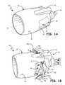
- FIG. 1Ais a perspective of an embodiment of a gas turbine engine and nacelle assembly with an embodiment of a pivot thrust reverser, shown in a stowed position.
- FIG. 1Bis a perspective view of the gas turbine engine and nacelle assembly of FIG. 1A with the pivot thrust reverser shown in a deployed position.
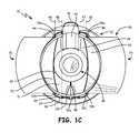
- FIG. 1Cis an aft elevation view of the gas turbine engine and nacelle assembly of FIG. 1B .
- FIG. 2Ais a perspective view of the pivot thrust reverser in the deployed position showing the inner panels connected to the outer panels by multi-bar linkages.
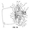
- FIG. 2Bis a perspective view of the nacelle assembly with the pivot thrust reverser in the deployed position with three actuators and part of a pylon included. Portions of the nacelle assembly and pylon are omitted to reveal otherwise concealed structures.
- FIG. 3Ais a plan view of the tandem pivot door subassembly, shown in isolation, in the stowed position.
- FIG. 3Bis a plan view of the tandem pivot door subassembly, shown in isolation, in the deployed position.
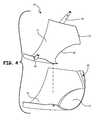
- FIG. 4is an exploded perspective view of an inner panel and outer panel of the tandem pivot door subassembly.
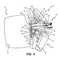
- FIG. 5is a perspective view of part of the nacelle and pylon with another embodiment of a pivot thrust reverser in the deployed position with three actuators. Portions of the nacelle assembly and pylon are omitted to reveal otherwise concealed structures.
- a pivot thrust reversercan be deployed to circumferentially surround (or, synonymously, contour around) a gas turbine engine inner bypass duct wall such that a fan bypass stream is interrupted and reversed with relatively little leakage, while a core stream and a nacelle ventilation stream are unobstructed or substantially unobstructed.
- thrust reverser pivot doorscan make up a portion of both a surface of a bypass duct (e.g., an outer duct wall) and an outer surface of a nacelle.
- the pivot doorscan be pivotally deployed from a stowed position to a deployed position, on pivot axises that are positionally fixed relative to the gas turbine engine, by at least three actuators configured so as to avoid interference from engine and/or nacelle structures.
- FIGS. 1A, 1B, and 1Cshow an embodiment of gas turbine engine and nacelle assembly 10 .
- FIG. 1Ais a perspective view of assembly 10 with an embodiment of pivot thrust reverser 20 in the stowed position.
- FIG. 1Bshows a perspective view of assembly 10 with pivot thrust reverser 20 in a deployed position.
- FIG. 1Cis an aft elevation view of assembly 10 shown with pivot thrust reverser 20 in the deployed position.
- Assembly 10includes nacelle 12 , outer surface 14 of nacelle 12 , pylon 16 , engine 18 , nacelle opening 19 , pivot thrust reverser 20 with first tandem pivot door subassembly 22 and second tandem pivot door subassembly 24 , bypass duct 26 , outer surface 28 and inner surface 30 of bypass duct 26 , inner panel 31 and outer panel 32 of first tandem pivot door subassembly 22 , inner panel 34 and outer panel 35 of second tandem pivot door subassembly 24 , upper bifurcation (bi-fi) fairing 40 , lower bi-fi fairing 42 , linkages 44 and 48 of first tandem pivot door subassembly 22 , linkages 46 and 50 of second tandem pivot door subassembly 24 , pivot axis 45 of inner panel 31 , pivot axis 47 of inner panel 34 , pivot axis 49 of outer panel 32 , pivot axis 51 of outer panel 35 , actuator 52 a , fixed pivot connection points 53 a and 53
- Nacelle 12provides an annular housing within which a substantial portion of engine 18 is located.
- Engine 18is aligned on axis A of assembly 10 in the illustrated embodiment, and can be connected to pylon 16 at an attachment location.
- Engine 18includes a compressor section, a combustor section, and a turbine section (those sections not specifically shown), which in combination produce hot combustion gases that provide operational energy for engine 18 .
- the attachment location in the illustrated embodimentsis pylon 16 , which provides a means for mounting assembly 10 to an aircraft (not shown).
- Pivot thrust reverser 20includes both first tandem pivot door subassembly 22 and second tandem pivot door subassembly 24 . As shown here, second tandem pivot door subassembly 24 is spaced approximately 180° from first tandem pivot door subassembly 22 relative to axis A of assembly 10 .
- first tandem pivot door subassembly 22 and second tandem pivot door subassembly 24each form a portion of outer surface 14 , such that outer surface 14 is substantially smooth at all points along an exterior of nacelle 12 , including interfaces with first tandem pivot door subassembly 22 and second tandem pivot door subassembly 24 . Because first tandem pivot door subassembly 22 and second tandem pivot door subassembly 24 provide a smooth outer surface 14 of nacelle 12 , pivot thrust reverser 20 tends to reduce a risk of undesired aerodynamic concerns.
- bypass duct 26provides an outer surface of a wall covering engine 18 .
- Bypass duct 26is defined by the annular space within nacelle 12 between inner surface 30 and outer surface 28 of bypass duct 26 .
- Outer surface 28 of bypass duct 26is formed by a duct wall at the interior of nacelle 12 , and first tandem pivot door subassembly 22 and second tandem pivot door subassembly 24 when in the stowed position, as shown in FIG. 1A .
- inner panel 31 and outer panel 32 of first tandem pivot door subassembly 22are connected by a multi-bar linkage (further described with regard to FIG. 2A ).
- Inner panel 34 and outer panel 35 of second tandem pivot door subassembly 24are also connected by another multi-bar linkage (further described with regard to FIG. 2A ).
- the connection between inner panels 31 and 34 and outer panels 32 and 35can be made by differing numbers and configurations of linkages, or other types of mechanisms, as desired for particular applications.
- Both first tandem pivot door subassembly 22 and second tandem pivot door subassembly 24can pivot on respective pivot axises that are each positionally fixed relative to their respective mounting locations. Thus, first tandem pivot door subassembly 22 and second tandem pivot door subassembly 24 can merely pivot into the deployed position, without requiring any translation of portions of nacelle 12 , first tandem pivot door subassembly 22 , or second tandem pivot door subassembly 24 .
- Both first tandem pivot door subassembly 22 and second tandem pivot door subassembly 24pivot into opening 19 so as to open upstream from an aft end of nacelle 12 , such that first tandem pivot door subassembly 22 and second tandem pivot door subassembly 24 pivot open inside of nacelle 12 , obstructing flow through bypass duct 26 .
- Fan bypass stream F 1is relatively cold air which enters through the fan at the front end of nacelle 12 and passes through bypass duct 26 .
- fan bypass stream F 1exits from an aft end of nacelle 12 and can provide a majority of the propulsion generated by high bypass gas turbine engine 18 .
- pivot thrust reverser 20is in the deployed position, as shown in FIGS.
- first tandem pivot door subassembly 22 and second tandem pivot door subassembly 24open inside of nacelle 12 and obstruct at least a portion of the flow of fan bypass stream F 1 through bypass duct 26 , such that a redirected fan bypass stream F 1 no longer exits from the aft end of nacelle 12 , but is instead diverted in another direction.
- Redirected fan bypass stream F 1is redirected by deployed pivot thrust reverser 20 to flow in the forward, or upstream, direction shown in FIGS. 1B and 1C .
- pivot thrust reverser 20is configured such that there need not be any actuators, linkages, or other obstructions present in F 1 flow path when pivot thrust reverser 20 is in the deployed position, which could otherwise obstruct the flow of redirected fan bypass stream F 1 in the forward direction, thus reducing the effectiveness of pivot thrust reverser 20 .
- Redirecting fan bypass stream F 1 as showncan restrict or prevent fan bypass stream F 1 from providing forward propulsion, but can also actively provide deceleration.
- nacelle ventilation stream F 2 and core stream F 3which flow through the inside of engine 18 , can remain substantially unobstructed and continue to flow out downstream of engine 18 when pivot thrust reverser 20 is deployed in substantially the same manner as when pivot thrust reverser 20 is in the stowed position.
- outer panel 32is larger than inner panel 31 of first tandem pivot door subassembly 22 and outer panel 35 is larger than inner panel 34 of second tandem pivot door subassembly 24 .
- inner panels 31 and 34 and outer panels 32 and 35can be any combination of sizes, with the relevant configurations adjusted and opening 19 sized accordingly.
- outer panels 32 and 35not only provide structural support to inner panels 31 and 34 respectively, but also take on functional roles.
- Larger outer panels 32 and 35provide additional guidance, in addition to the guidance provided by inner panels 31 and 34 , for redirecting fan bypass stream F 1 in the appropriate forward direction needed to provide deceleration.
- pivot thrust reverser 20operates more effectively.
- larger outer panels 32 and 35also can function as an air break, and thus provide deceleration in addition to that provided by redirected fan bypass stream F 1 .
- Engine 18is centered inside nacelle 12 , in the illustrated embodiment, and thus is axially aligned with the engine fan at the front end of nacelle 12 (axis A of FIG. 1A ).
- Upper bi-fi fairing 40 and lower bi-fi fairing 42serve to interconnect nacelle 12 and engine 18 , as well as provide additional stiffness for nacelle 12 and space for wires, tubes and other similar components.
- linkage 44provides a hinged connection between inner panel 31 (of first tandem pivot door subassembly 22 ) and pivot axis 45 , with linkage 44 fixed to nacelle 12 at pivot axis 45 .
- linkage 46provides a hinged connection between inner panel 34 (of second tandem pivot door subassembly 24 ) and pivot axis 47 , with linkage 46 fixed to nacelle 12 at pivot axis 47 .
- Pivot axis 45 of inner panel 31 and pivot axis 47 of inner panel 34can be positionally fixed relative to assembly 10 , nacelle 12 , and/or engine 18 .
- Pivot axis 45is spaced from inner panel 31 and extends from linkage 44 to linkage 48 .
- pivot axis 47is spaced from inner panel 34 and extends from linkage 46 to linkage 50 .
- Linkage 48provides a connection between inner panel 31 and actuator 52 a
- linkage 50provides a connection between inner panel 34 and actuator 52 a.
- Outer panel 32(of first tandem pivot door subassembly 22 ) is fixed to nacelle 12 at fixed pivot connection points 53 a and 53 b , and pivots about pivot axis 49 .
- Points 53 a and 53 bprovide hinge points for outer panel 32 and are located at or near a perimeter of outer panel 32 in nacelle 12 , between outer surface 14 of nacelle 12 and outer surface 28 of bypass duct 26 , on pivot axis 49 .
- Outer panel 35(of second tandem pivot door subassembly 24 ) is fixed to nacelle 12 at fixed pivot connection points 54 a and 54 b , and pivots about pivot axis 51 .
- Points 54 a and 54 bprovide hinge points for outer panel 35 and are located at or near a perimeter of outer panel 35 in nacelle 12 , between outer surface 14 of nacelle 12 and outer surface 28 of bypass duct 26 , on pivot axis 51 .
- Pivot axis 49 of outer panel 32 and pivot axis 51 of outer panel 35can each be positionally fixed relative to assembly 10 , nacelle 12 , and/or engine 18 .
- Pivot axis 49extends from point 53 a to point 53 b .
- Pivot axis 51extends from point 54 a to point 54 b .
- inner panels 31 and 34can maintain connection with outer panels 32 and 35 by multi-bar linkages 41 and 43 .
- inner panel 31 and outer panel 32 of first tandem pivot door subassembly 22can pivot simultaneously about different pivot axises 45 and 49 without translating relative to those axises 45 and 49 .
- inner panel 34 and outer panel 35 of second tandem pivot door subassembly 24can pivot simultaneously about different pivot axises 47 and 51 without translating.
- Actuator 52 aalong with actuators 52 b and 52 c (shown in FIGS. 2A and 2B ), can pivot both first tandem pivot door subassembly 22 and second tandem pivot door subassembly 24 from the stowed position to the deployed position without translation of first tandem pivot door subassembly 22 , second tandem pivot door subassembly 24 , or any portion of nacelle 12 .
- first tandem pivot door subassembly 22 and second tandem pivot door subassembly 24circumferentially surround inner surface 30 of bypass duct 26 .
- Inner panel 31 of first tandem pivot door subassembly 22 and inner panel 34 of second tandem pivot door subassembly 24are each configured to circumferentially surround inner surface 30 of bypass duct 26 such that an at least partially sealing, mating relationship is formed and there is relatively little leakage of fan bypass stream F 1 (the only leakage coming from portions where bypass duct 26 is visible). This means that nearly all of fan bypass stream F 1 is redirected, resulting in a highly efficient pivot thrust reverser 20 . Yet, at the same time entire pivot thrust reverser 20 provides a simplified design requiring minimal parts, and thus increases reliability and reduces maintenance costs.
- FIGS. 2A and 2Bshow perspective views of pivot thrust reverser 20 in the deployed position with three actuators 52 a , 52 b , and 52 c .
- FIG. 2Ashows pivot thrust reverser 20 in isolation with actuators 52 a , 52 b , and 52 c .
- FIG. 2Bshows a top of pivot thrust reverser 20 with a portion of both nacelle 12 and pylon 16 present. Certain assembly 10 components are left out for simplicity.
- top link 41 a and bottom link 41 b of first tandem pivot door subassembly 22top link 43 a and bottom link 43 b of second tandem pivot door subassembly 24 , actuators 52 b and 52 c , top overhang 55 a and bottom overhang 55 b of outer panel 32 of first tandem pivot door subassembly 22 , top overhang 56 a and bottom overhang 56 b of outer panel 35 of second tandem pivot door subassembly 24 , multi-bar linkage 41 of first tandem pivot door subassembly 22 , multi-bar linkage 43 of second tandem pivot door subassembly 24 , surfaces 57 a and 57 b of outer panel 32 of first tandem pivot door subassembly 22 , surfaces 58 a and 58 b of outer panel 35 of second tandem pivot door subassembly 24 , motors 60 a , 60 b , and 60 c , threaded rods
- Multi-bar linkage 41can include link 41 a , link 41 b , and linkage 48 .
- Linkage 48provides a connection between inner panel 31 and actuator 52 a
- links 41 a and 41 bprovide a connection between inner panel 31 and outer panel 32 .
- multi-bar linkage 43can include link 43 a , link 43 b , and linkage 50 .
- Linkage 50provides a connection between inner panel 31 and actuator 52 a
- links 43 a and 43 bprovide a connection between inner panel 34 and outer panel 35 .
- multi-bar linkages 41 and 43could include alternate and/or additional connections between actuator 52 a , inner panels 31 and 34 , and/or outer panels 32 and 35 , respectively.
- Overhangs 55 a and 55 b of outer panel 32extend out over surfaces 57 a and 57 b , providing coverage of links 41 a and 41 b respectively when pivot thrust reverser 20 is in the stowed position.
- Overhangs 56 a and 56 b of outer panel 35extend out over surfaces 58 a and 58 b , providing coverage of links 43 a and 43 b when pivot thrust reverser 20 is in the stowed position.
- overhangs 55 a , 55 b , 56 a , and 56 bhelp alleviate aerodynamic concerns of nacelle 12 when pivot thrust reverser 20 is stowed.
- Actuators 52 a , 52 b , and 52 care located between outer surface 28 of bypass duct 26 and outer surface 14 of nacelle 12 (see also FIG. 1C ). Outer surface 28 is cut-away in FIG. 2B to show the location of motor 60 a of actuator 52 a .
- actuator 52 aalone, without the presence of actuators 52 b and/or 52 c , would not be able to keep pivot doors 22 and 24 is the proper deployed positions.
- the location of pylon 16prevents the use of a second actuator opposite (i.e. 180° apart from relative to axis A) actuator 52 a . Therefore, actuators 52 a , 52 b , and 52 c are configured to keep tandem pivot door subassemblies 22 and 24 secured in the deployed position, while at the same time avoiding pylon 16 interference.
- Actuators 52 b and 52 care both located near pylon 16 , on opposite side of pylon 16 .
- Actuator 52 bis located circumferentially between pylon 16 and edge 74 of inner panel 31 of first tandem pivot door subassembly 22 when first tandem pivot door subassembly 22 is in the stowed position.
- Actuator 52 cis located circumferentially between pylon 16 and edge 75 of inner panel 34 of second tandem pivot door subassembly 24 when second tandem pivot door subassembly 24 is in the stowed position.
- the configuration of the illustrated embodimentalso does not require any actuators, linkages, or other obstructions be present in redirected fan bypass stream F 1 flow path when pivot thrust reverser 20 is in the deployed position, thus increasing the effectiveness of pivot thrust reverser 20 .
- Actuators 52 a , 52 b , and 52 ccan be, for example, bolt screw linear (i.e. traveling nut) actuators as shown here that include motors 60 a , 60 b , and 60 c , threaded rods 62 a , 62 b , and 62 c , and threaded knuckleheads 64 a , 64 b , and 64 c .
- various other types of actuatorscan also be used in alternate embodiments to pivot both first tandem pivot door subassembly 22 and second tandem pivot door subassembly 24 between the stowed and deployed positions.
- Motors 60 a , 60 b , and 60 cmove threaded knuckleheads 64 a , 64 b , and 64 c down threaded rods 62 a , 62 b , and 62 c towards motors 60 a , 60 b , and 60 c , and in so doing, pivot inner panel 31 on pivot axis 45 . Then, due to the connection between inner panel 31 and outer panel 32 by multi-bar linkage 41 , outer panel 32 is simultaneously made to pivot on pivot axis 49 .
- first tandem pivot door subassembly 22 and second tandem pivot door subassembly 24are pivoted by actuators 52 a , 52 b , and 52 c about different pivot axises between stowed and deployed positions without translating (relative to assembly 10 ).
- inner panel 31 of first tandem pivot door subassembly 22contains cutout 66 in aft edge 70 and inner panel 34 of second tandem pivot door subassembly 24 contains cutout 68 in aft edge 72 .
- Both cutouts 66 and 68are located on lower portions of aft edges 70 and 72 respectively.
- aft edge 70 of inner panel 31faces aft edge 72 of inner panel 34 .
- cutout 66is aligned to face cutout 68 when tandem pivot door subassemblies 22 and 24 are deployed, forming an opening in pivot thrust reverser 20 to accommodate engine 18 .
- Both cutout 66 and cutout 68can be arc-shaped, resulting in the opening in pivot thrust reverser 20 being generally circular in shape. However, in alternative embodiments, cutouts 66 and 68 can have various different shapes and be placed at any location on inner panels 31 and 34 . Also, when deployed, aft edges 70 and 72 of inner panels 31 and 34 extend longitudinally beyond aft edges of outer panels 32 and 35 , such that aft edges 70 and 72 do not have outer panels 32 and 35 located directly behind them.
- FIGS. 3A and 3Bshow a plan view of actuator 52 c and second tandem pivot door subassembly 24 in isolation, with second tandem pivot door subassembly 24 pivoted from the stowed to the deployed position.
- FIG. 3Ashows second tandem pivot door subassembly 24 in the stowed position.
- FIG. 3Bshows second tandem pivot door subassembly 24 pivoted to the deployed position.
- Fixed pivot point 45is located on pivot axis 47 (shown in FIG. 1C ) and is a pivot connection point about which inner panel 34 rotates.
- Point 54 bas discussed for FIG.
- 1Cis located on pivot axis 51 , and is a pivot connection point about which outer panel 35 is hinged to nacelle 12 and pivotally rotates.
- point 54 bis located at or near a perimeter of outer panel 35 , and more specifically is at or near an aft end of outer panel 35 which can pivot inside of nacelle 12 .
- Link 80provides a connection between threaded knucklehead 64 c of actuator 52 c and linkage 46 .
- second tandem pivot door subassembly 24is deployed by pivoting inner panel 34 and outer panel 35 simultaneously about different pivot points. This allows second tandem pivot door subassembly 24 to deploy and avoid interference from nacelle 12 that otherwise would occur due to the location of second tandem pivot door subassembly 24 .
- FIG. 4is an exploded perspective view of inner panel 31 and outer panel 32 of first tandem pivot door subassembly 22 of pivot thrust reverser 20 . Included, in addition to that shown and described previously, are inward-facing protrusion 67 and side protrusion 69 on outer panel 32 . Inner panel 31 is placed on top of outer panel 32 , with links 41 a and 41 b then added to provide the connection between inner panel 31 and outer panel 32 . When connected and stowed, aft edge 70 of inner panel 31 extends only up to where side protrusion 69 begins, such that side protrusion 69 at an aft edge of outer panel 32 extends longitudinally beyond aft edge 70 .
- inward-facing protrusion 67is of a shape complimentary with cutout 66 in aft edge 70 of inner panel 31 , such that inward-facing protrusion 67 protrudes into the location of cutout 66 when inner panel 31 is placed on top of outer panel 32 .
- side protrusion 69is of a shape complimentary with curved aft edge 70 of inner panel 31 , such that side protrusion 69 protrudes up from an interface of aft edge 70 and side protrusion 69 .
- Protrusions 67 and 69then allow first tandem pivot door subassembly 22 to both provide a substantially smooth outer surface 28 of bypass duct 26 (see FIG.
- FIG. 5shows a perspective view of another embodiment of pivot thrust reverser in the deployed position with three actuators 52 a , 52 b , and 52 c and part of pylon 16 included. Portions of nacelle 12 and pylon 16 are omitted to reveal otherwise concealed structures.
- Pivot thrust reverser 20is generally configured the same way as pivot thrust reverser 20 , except that inner panels 31 and 34 are connected to outer panels 32 and 35 , respectively, with sliding rails 36 and 38 rather than multi-bar linkages 41 and 43 of pivot thrust reverser 20 .
- two sliding railsare used to connect inner panel 34 to outer panel 35 , but any number of sliding rails, including a single rail, can be used to make the connection.
- Actuators 52 a , 52 b , and 52 care configured in the same manner as described for FIGS. 2A and 2B . Furthermore, first tandem pivot door subassembly 22 and second tandem pivot door subassembly 24 of pivot thrust reverser 20 are pivoted from the stowed position to the deployed position in same manner described herein for pivot thrust reverser 20 .
- the present embodimentsprovide a highly effective thrust reverser for use in a gas turbine engine. This is because configuring inner panels 31 and 34 with cutouts 66 and 68 to circumferentially surround inner surface 30 of bypass duct 26 as shown allows nearly all of fan bypass stream F 1 to be redirected in the appropriate direction, while at the same time minimizing the number of components needed to pivot both first and second tandem pivot door subassemblies 22 and 24 from the stowed to the deployed position without interference from nacelle 12 . This is turn decreases the weight of thrust reverser 20 while increasing the reliability of thrust reverser 20 . Additionally, the design of thrust reverser 20 avoids interference from obstructions and provides a modular assembly which allows for direct mounting of thrust reverser 20 in position.
- a pivot thrust reverserfor use in a gas turbine engine assembly, the pivot thrust reverser comprising a first tandem pivot door subassembly comprising an inner panel and an outer panel, wherein the inner panel and the outer panel are connected; a second tandem pivot door subassembly comprising an inner panel and an outer panel, wherein the inner panel and the outer panel are connected; a first actuator located on a first side of an attachment location to pivot the first tandem pivot door subassembly; a second actuator located on a second side of the attachment location to pivot the second tandem pivot door subassembly; and a third actuator located substantially radially opposite the attachment location to pivot both the first tandem pivot door subassembly and the second tandem pivot door subassembly, wherein the first tandem pivot door is configured to be pivoted from a stowed position to a deployed position by both the first actuator and the third actuator, and wherein the second tandem pivot door is configured to be pivoted from the stowed position to the deployed position by both the second actuator and
- pivot thrust reverser of the preceding paragraphcan optionally include, additionally and/or alternatively, any one or more of the following features, configurations, and/or additional components:
- the first actuator, the second actuator and the third actuatorare all located between a surface of a bypass duct and an outer surface of a nacelle.
- the first tandem pivot door and the second tandem pivot dooreach form both a portion of the surface of the bypass duct and a portion of the outer surface of the nacelle when in the stowed position.
- first tandem pivot door subassembly and the second tandem pivot door subassemblycircumferentially surround an inner surface of a bypass duct such that when the pivot thrust reverser is deployed during engine operation a fan bypass stream is redirected while both a core stream and a nacelle ventilation stream flow in the same manner as when the pivot thrust reverser is stowed.
- the inner panel and the outer panel of the first tandem pivot door subassemblyare configured to rotate simultaneously about different pivot axises, and wherein the inner panel and the outer panel of the second tandem pivot door subassembly are configured to rotate simultaneously about different pivot axises.
- the first actuator, the second actuator and the third actuatorare configured to pivot both the first tandem pivot door subassembly and the second tandem pivot door subassembly from the stowed position to the deployed position on respective pivot axises that are each positionally fixed relative to the gas turbine engine assembly.
- the pivot point of the inner panel of the first tandem pivot door subassemblyis located on a linkage operatively connected between an actuator and the inner panel of the first tandem pivot door subassembly, and wherein the pivot point of the outer panel of the first tandem pivot door subassembly is located at or near a perimeter of the outer panel of the first tandem pivot door subassembly.
- the second tandem pivot dooris spaced approximately 180° from the first tandem pivot door relative to an axis of the gas turbine engine.
- the second actuatoris circumferentially spaced from the first actuator.
- the first tandem pivot door inner panel and outer panelare connected by a first sliding rail, and wherein the second tandem pivot door inner panel and outer panel are connected by a second sliding rail.
- the inner panel and the outer panel of the first tandem pivot door subassemblyare connected by a third sliding rail.
- the first tandem pivot door inner panel and outer panelare connected by a multi-bar linkage.
- a method for use in a gas turbine engine assemblycomprising providing a first tandem pivot door subassembly comprising an inner panel and an outer panel; connecting the inner panel and the outer panel of the first tandem pivot door subassembly; and pivoting the first tandem pivot door subassembly from a stowed position to a deployed position with a first actuator and a third actuator.
- the method of the preceding paragraphcan optionally include, additionally and/or alternatively, the following techniques, steps, features and/or configurations:
- the inner panel and the outer panel of the first tandem pivot door subassemblyare connected to allow the inner panel and the outer panel to rotate simultaneously about different pivot axises.
- the inner panel and the outer panel of the second tandem pivot door subassemblyare connected to allow the inner panel and the outer panel to rotate simultaneously about different pivot axises.
- the inner panel and the outer panel of the first tandem pivot door subassemblyare connected by a first sliding rail, and wherein the inner panel and the outer panel of the second tandem pivot door subassembly are connected by a second sliding rail.
- the inner panel and the outer panel of the first tandem pivot door subassemblyare connected by a third sliding rail.
- the inner panel and the outer panel of the first tandem pivot door subassemblyare connected by a multi-bar linkage, and wherein the inner panel and the outer panel of the second tandem pivot door subassembly are connected by a multi-bar linkage.
- any relative terms or terms of degree used hereinsuch as “substantially”, “essentially”, “generally” and the like, should be interpreted in accordance with and subject to any applicable definitions or limits expressly stated herein. In all instances, any relative terms or terms of degree used herein should be interpreted to broadly encompass any relevant disclosed embodiments as well as such ranges or variations as would be understood by a person of ordinary skill in the art in view of the entirety of the present disclosure, such as to encompass ordinary manufacturing tolerance variations, incidental alignment variations, temporary alignment or shape variations induced by operational conditions, and the like.
- assembly 10can have many orientations during use, such as when utilized on an aircraft.
- aircraft usescan also include mounting assembly 10 such that thrust reverser 20 can deploy horizontally, vertically, or any angles in between.
Landscapes
- Engineering & Computer Science (AREA)
- Mechanical Engineering (AREA)
- Chemical & Material Sciences (AREA)
- Combustion & Propulsion (AREA)
- General Engineering & Computer Science (AREA)
- Aviation & Aerospace Engineering (AREA)
- Structures Of Non-Positive Displacement Pumps (AREA)
- Wind Motors (AREA)
Abstract
Description
Claims (12)
Priority Applications (1)
| Application Number | Priority Date | Filing Date | Title |
|---|---|---|---|
| US14/184,398US9695778B2 (en) | 2013-02-22 | 2014-02-19 | Tandem thrust reverser with multi-point actuation |
Applications Claiming Priority (6)
| Application Number | Priority Date | Filing Date | Title |
|---|---|---|---|
| US201361768166P | 2013-02-22 | 2013-02-22 | |
| US201361768160P | 2013-02-22 | 2013-02-22 | |
| US201361768172P | 2013-02-22 | 2013-02-22 | |
| US201361768171P | 2013-02-22 | 2013-02-22 | |
| US201361768154P | 2013-02-22 | 2013-02-22 | |
| US14/184,398US9695778B2 (en) | 2013-02-22 | 2014-02-19 | Tandem thrust reverser with multi-point actuation |
Publications (2)
| Publication Number | Publication Date |
|---|---|
| US20150122912A1 US20150122912A1 (en) | 2015-05-07 |
| US9695778B2true US9695778B2 (en) | 2017-07-04 |
Family
ID=51387149
Family Applications (6)
| Application Number | Title | Priority Date | Filing Date |
|---|---|---|---|
| US14/184,335Active2035-08-31US9670876B2 (en) | 2013-02-22 | 2014-02-19 | Tandem thrust reverser with sliding rails |
| US14/184,376Active2035-12-11US9581108B2 (en) | 2013-02-22 | 2014-02-19 | Pivot thrust reverser with multi-point actuation |
| US14/184,398Active2035-12-16US9695778B2 (en) | 2013-02-22 | 2014-02-19 | Tandem thrust reverser with multi-point actuation |
| US14/184,368Active2035-06-18US9822734B2 (en) | 2013-02-22 | 2014-02-19 | Tandem thrust reverser with multi-bar linkage |
| US14/184,313Active2035-06-04US9631578B2 (en) | 2013-02-22 | 2014-02-19 | Pivot thrust reverser surrounding inner surface of bypass duct |
| US15/586,386ActiveUS9970388B2 (en) | 2013-02-22 | 2017-05-04 | Tandem thrust reverser with sliding rails |
Family Applications Before (2)
| Application Number | Title | Priority Date | Filing Date |
|---|---|---|---|
| US14/184,335Active2035-08-31US9670876B2 (en) | 2013-02-22 | 2014-02-19 | Tandem thrust reverser with sliding rails |
| US14/184,376Active2035-12-11US9581108B2 (en) | 2013-02-22 | 2014-02-19 | Pivot thrust reverser with multi-point actuation |
Family Applications After (3)
| Application Number | Title | Priority Date | Filing Date |
|---|---|---|---|
| US14/184,368Active2035-06-18US9822734B2 (en) | 2013-02-22 | 2014-02-19 | Tandem thrust reverser with multi-bar linkage |
| US14/184,313Active2035-06-04US9631578B2 (en) | 2013-02-22 | 2014-02-19 | Pivot thrust reverser surrounding inner surface of bypass duct |
| US15/586,386ActiveUS9970388B2 (en) | 2013-02-22 | 2017-05-04 | Tandem thrust reverser with sliding rails |
Country Status (1)
| Country | Link |
|---|---|
| US (6) | US9670876B2 (en) |
Cited By (4)
| Publication number | Priority date | Publication date | Assignee | Title |
|---|---|---|---|---|
| US10040563B1 (en)* | 2013-04-11 | 2018-08-07 | Geoffrey P. Pinto | Dual panel actuator system for jet engines |
| US10180117B2 (en)* | 2013-02-22 | 2019-01-15 | United Technologies Corporation | Full ring sliding nacelle with thrust reverser |
| US11041460B2 (en) | 2017-10-25 | 2021-06-22 | Rohr, Inc. | Synchronization mechanism for pivot door thrust reversers |
| US11396854B2 (en) | 2017-10-25 | 2022-07-26 | Rohr, Inc. | Hinge mechanism for pivot door thrust reversers |
Families Citing this family (25)
| Publication number | Priority date | Publication date | Assignee | Title |
|---|---|---|---|---|
| FR2968635B1 (en)* | 2010-12-14 | 2012-12-14 | Aircelle Sa | DOUBLE-FLOW AIRCRAFT TURBOREACTOR NACELLE |
| US9670876B2 (en) | 2013-02-22 | 2017-06-06 | United Technologies Corporation | Tandem thrust reverser with sliding rails |
| US9573695B2 (en) | 2013-02-22 | 2017-02-21 | United Technologies Corporation | Integrated nozzle and plug |
| FR3016863B1 (en)* | 2014-01-29 | 2017-05-26 | Snecma | NACELLE FOR AIRCRAFT TURBO AIRCRAFT |
| US10352248B2 (en) | 2014-10-01 | 2019-07-16 | United Technologies Corporation | Synchronized air modulating system |
| US9835043B2 (en) | 2014-10-01 | 2017-12-05 | United Technologies Corporation | Guided binding-resistant actuation apparatus and method |
| US9669938B2 (en) | 2015-01-16 | 2017-06-06 | United Technologies Corporation | Upper bifi frame for a gas turbine engine and methods therefor |
| US10239628B2 (en)* | 2016-09-15 | 2019-03-26 | Rohr, Inc. | Set of latches with identical components for nacelle doors |
| FR3060660B1 (en)* | 2016-12-20 | 2019-05-17 | Safran Nacelles | AIRCRAFT TURBO BURNER BOAT, PROPULSIVE AND AIRCRAFT ASSEMBLY COMPRISING SUCH A NACELLE |
| FR3062371B1 (en)* | 2017-01-31 | 2019-03-29 | Airbus | NACELLE OF A TURBOJET ENGINE COMPRISING AN INVERTER SHUTTER |
| CN107009165B (en)* | 2017-04-06 | 2018-11-27 | 武汉船用机械有限责任公司 | Radome fairing clamping tooling |
| US10343786B2 (en)* | 2017-06-28 | 2019-07-09 | General Electric Company | System and method of operating a ducted fan propulsion system during aircraft taxi |
| GB2564891A (en)* | 2017-07-26 | 2019-01-30 | Short Brothers Plc | Nacelle with thrust reverser |
| US11111879B2 (en) | 2018-01-12 | 2021-09-07 | Rohr, Inc. | Thrust reverser pivot door with extended forward edge |
| FR3079213B1 (en)* | 2018-03-23 | 2020-02-28 | Airbus Operations | NACELLE EQUIPPED WITH A REVERSING SYSTEM COMPRISING DOORS AND ANTI-VIBRATION SYSTEMS OF THE DOORS IN THE STORED POSITION |
| US10830177B2 (en) | 2018-05-01 | 2020-11-10 | Rohr, Inc. | Articulating pivot point post-exit thrust reverser |
| US10724474B2 (en) | 2018-05-01 | 2020-07-28 | Rohr, Inc. | Hybrid articulating/translating trailing edge reverser |
| US11338926B2 (en)* | 2018-08-10 | 2022-05-24 | Rolls-Royce North American Technologies Inc. | Aircraft with electric propulsor |
| US11346304B2 (en) | 2018-09-06 | 2022-05-31 | Rohr, Inc. | Thrust reverser single degree of freedom actuator mechanism systems and methods |
| US11300077B2 (en) | 2018-10-02 | 2022-04-12 | Rohr, Inc. | Deployable fairing for door reversers systems and methods |
| US11333102B2 (en)* | 2018-09-06 | 2022-05-17 | Rohr, Inc. | Thrust reverser actuation arrangement and deployable fairing systems and methods |
| US11753968B2 (en) | 2021-08-23 | 2023-09-12 | Rolls-Royce Deutschland Ltd & Co Kg | Nacelle cowling structure for a turbomachine |
| US12000358B1 (en)* | 2023-02-14 | 2024-06-04 | Pratt & Whitney Canada Corp. | Gas turbine engine nozzle loft for thrust reverser |
| CN116591858B (en)* | 2023-05-26 | 2025-08-05 | 西北工业大学 | Turbofan engine thrust reverser and its actuating mechanism |
| US20250277475A1 (en)* | 2024-03-04 | 2025-09-04 | Textron Aviation Inc. | Aircraft Thrust Reverser Corrosion Shield |
Citations (88)
| Publication number | Priority date | Publication date | Assignee | Title |
|---|---|---|---|---|
| US2282552A (en) | 1940-11-15 | 1942-05-12 | B & H Mfg Co Inc | Nongasket flange |
| US2526791A (en) | 1945-09-29 | 1950-10-24 | Frederick Archibald Pillet | Fastening device |
| US3067968A (en) | 1958-12-29 | 1962-12-11 | Heppenstall Charles William | Retractable jet engine noise suppressor |
| US3601992A (en)* | 1970-06-10 | 1971-08-31 | Rohr Corp | Thrust reversing apparatus |
| US3614037A (en) | 1969-09-22 | 1971-10-19 | Boeing Co | Aircraft combination thrust reverser and sound suppressor and a particular full range balanced thrust reverser |
| US3699682A (en) | 1971-01-04 | 1972-10-24 | Mc Donnell Douglas Corp | Turbofan engine thrust reverser |
| US3764096A (en)* | 1972-02-24 | 1973-10-09 | Rohr Industries Inc | Thrust reversing apparatus |
| US4196856A (en) | 1977-11-25 | 1980-04-08 | The Boeing Company | Variable geometry convergent divergent exhaust nozzle |
| US4278220A (en) | 1979-03-30 | 1981-07-14 | The United States Of America As Represented By The Administrator Of The National Aeronautics And Space Administration | Thrust reverser for a long duct fan engine |
| US4410152A (en) | 1980-07-04 | 1983-10-18 | Society De Construction Des Avions | Thrust reverser for a jet engine, more especially for equipping an aircraft |
| US4442987A (en) | 1980-12-23 | 1984-04-17 | Societe Nationale D'etude Et De Construction De Moteurs D'aviation "S.N.E.C.M.A." | Guidance device for the moving fairing of a thrust reverser system |
| US4485970A (en) | 1981-05-29 | 1984-12-04 | Societe De Construction Des Avions Hurel-Dubois | Thrust reversal device for air-craft turbojets |
| US4825644A (en) | 1987-11-12 | 1989-05-02 | United Technologies Corporation | Ventilation system for a nacelle |
| US4894985A (en) | 1987-07-29 | 1990-01-23 | Societe Anonyme Dite: Hispano Suiza | Thrust reverser with movable deflector |
| US4920744A (en) | 1987-11-06 | 1990-05-01 | Aerospatiale-Societe Nationale Industrielle | Ducted fan turbine engine |
| US4960243A (en) | 1988-10-20 | 1990-10-02 | Societe Anonyme Dite Hispano-Suiza | Thrust reverser for a turbojet engine |
| US5039171A (en) | 1989-08-18 | 1991-08-13 | Societe Anonyme Dite Hispano-Suiza | Multi-panel thrust reverser door |
| US5090197A (en)* | 1989-08-23 | 1992-02-25 | Societe Anonyme Dite Hispano Suiza | Pivoting door cascade thrust reverser |
| US5110069A (en) | 1990-11-30 | 1992-05-05 | General Electric Company | Single pivot overwing thrust reverser |
| US5117630A (en) | 1990-02-12 | 1992-06-02 | Rohr Industries, Inc. | Pivoting door thrust reverser |
| US5267438A (en) | 1991-11-15 | 1993-12-07 | Societe Hispano-Suiza | Thrust reverser for a turbofan engine |
| US5315821A (en) | 1993-02-05 | 1994-05-31 | General Electric Company | Aircraft bypass turbofan engine thrust reverser |
| EP0515263B1 (en) | 1991-05-23 | 1994-08-17 | Societe Nationale D'etude Et De Construction De Moteurs D'aviation "Snecma" | Thrust reverser for high by-pass ratio turbofan |
| WO1995028318A1 (en) | 1994-04-18 | 1995-10-26 | Short Brothers Plc | An aircraft propulsive power unit |
| US5497961A (en) | 1991-08-07 | 1996-03-12 | Rolls-Royce Plc | Gas turbine engine nacelle assembly |
| EP0756078A1 (en) | 1995-07-26 | 1997-01-29 | AEROSPATIALE Société Nationale Industrielle | Bypass turbofan engine with thrust reverse deflector doors |
| US5609313A (en) | 1993-01-26 | 1997-03-11 | Short Brothers Plc | Aircraft propulsive power unit |
| US5642960A (en) | 1994-08-09 | 1997-07-01 | Arturo Salice S.P.A. | Fastening element |
| US5863014A (en) | 1996-12-19 | 1999-01-26 | Societe De Construction Des Avions Hurel-Dubois | Thrust reverser for high bypass fan engine |
| EP0728934B1 (en) | 1995-02-21 | 1999-05-06 | Hispano-Suiza Aérostructures | Thrust reverser for a turbofan engine |
| US5970704A (en)* | 1996-07-18 | 1999-10-26 | Societe Hispano-Suiza | Pivoting door thrust reverser with sliding panel |
| US5974783A (en) | 1996-12-26 | 1999-11-02 | Societe Hispano-Suiza | Turbojet engine thrust reverser having movable rear baffle pivattally connected by forward and rear linkrods which are totally enclosed in the forward thrust mode |
| EP0761947B1 (en) | 1995-08-29 | 2000-05-24 | Burbank Aeronautical Corporation II | Noise reduction kit for turbofan engine |
| US6079201A (en) | 1996-02-15 | 2000-06-27 | Societe Hispano--Suiza | Self-closing pivoting door thrust reverser |
| US6151884A (en) | 1997-06-05 | 2000-11-28 | Hispano Suiza Aerostructures | Turbojet engine thrust reverser door spoilers with motion controlling drive system |
| US6170255B1 (en) | 1998-02-04 | 2001-01-09 | Hispano-Suiza Aerostructures | Turbojet thrust reverser with downstream obstacles |
| EP0771945B1 (en) | 1995-11-02 | 2001-01-10 | Hispano-Suiza Aerostructures | Thrust reverser with secondary flaps for a turbofan engine |
| US6179249B1 (en) | 1996-12-26 | 2001-01-30 | Aerospatiale Societe Nationale Industrielle | Turbojet pod with laminar flow |
| US6293495B1 (en) | 1999-12-08 | 2001-09-25 | Rohr, Inc. | Pivoting door thrust reverser system for turbofan aircraft jet engine |
| US6296495B1 (en) | 1999-11-05 | 2001-10-02 | Hon Hai Precision Ind. Co., Ltd. | Land grid package connector |
| EP0789140B1 (en) | 1996-02-08 | 2001-11-07 | Societe De Construction Des Avions Hurel-Dubois | Sealing for a pivoting thrust reverser door |
| US6340135B1 (en) | 2000-05-30 | 2002-01-22 | Rohr, Inc. | Translating independently mounted air inlet system for aircraft turbofan jet engine |
| US6568172B2 (en) | 2001-09-27 | 2003-05-27 | The Nordam Group, Inc. | Converging nozzle thrust reverser |
| EP0822327B1 (en) | 1996-08-01 | 2003-08-27 | Hispano-Suiza | Thrust reverser for a turbofan engine with thrust reverser doors which form scoops |
| US20030218094A1 (en) | 2002-05-21 | 2003-11-27 | Jean-Pierre Lair | Variable area thrust reverser nozzle |
| US6786038B2 (en) | 2002-02-22 | 2004-09-07 | The Nordam Group, Inc. | Duplex mixer exhaust nozzle |
| US20050039438A1 (en) | 2003-03-22 | 2005-02-24 | Jean-Pierre Lair | Toggle interlocked thrust reverser |
| US20050084325A1 (en) | 2003-10-16 | 2005-04-21 | Eastman Kodak Company | High reliability precision latch |
| US20050151012A1 (en)* | 2003-10-02 | 2005-07-14 | Jean-Pierre Lair | Spider actuated thrust reverser |
| US6968675B2 (en) | 2002-10-29 | 2005-11-29 | Rohr, Inc. | Cascadeless fan thrust reverser with plume control |
| US7127880B2 (en) | 2003-08-29 | 2006-10-31 | The Nordam Group, Inc. | Induction coupled variable nozzle |
| US20060288688A1 (en) | 2005-06-22 | 2006-12-28 | Jean-Pierre Lair | Turbofan core thrust spoiler |
| US20080072570A1 (en) | 2006-09-21 | 2008-03-27 | Jean-Pierre Lair | Thrust reverser nozzle for a turbofan gas turbine engine |
| US20080098720A1 (en) | 2004-12-08 | 2008-05-01 | Rolls-Royce Plc | Securing assembly |
| US20080302083A1 (en) | 2007-06-05 | 2008-12-11 | Sloan Mark L | Internal mixing of a portion of fan exhaust flow and full core exhaust flow in aircraft turbofan engines |
| US7484356B1 (en) | 2005-07-26 | 2009-02-03 | Aeronautical Concepts Of Exhaust, Llc | Cascade reverser without blocker doors |
| US20090260344A1 (en) | 2008-04-21 | 2009-10-22 | Rolls-Royce Plc | Rear fan case for a gas turbine engine |
| US20090288386A1 (en) | 2006-10-12 | 2009-11-26 | Marshall Richard M | Tri-body variable area fan nozzle and thrust reverser |
| US20090313969A1 (en) | 2008-06-19 | 2009-12-24 | Pratt & Whitney Canada Corp. | Thrust Reverser for a Turbofan Gas Turbine Engine |
| US20100008772A1 (en) | 2007-02-14 | 2010-01-14 | Aircelle | Nacelle for the jet engine of an aircraft |
| US20100107599A1 (en) | 2007-04-04 | 2010-05-06 | Aircelle | Thrust reverser for a jet engine |
| US20100139242A1 (en) | 2006-10-23 | 2010-06-10 | Aircelle | Thrust reverser with grids for jet engine |
| US20100170984A1 (en) | 2007-06-01 | 2010-07-08 | Airbus Operations | Engine assembly for aircraft with sliding nancelle |
| US7784765B2 (en) | 2006-12-01 | 2010-08-31 | Fujifilm Corporation | Mold, method for producing the same and magnetic recording medium |
| US7784735B2 (en) | 2005-06-30 | 2010-08-31 | Airbus France | Aircraft pod and aircraft equipped with at least one such pod |
| US20100270428A1 (en) | 2009-04-24 | 2010-10-28 | United Technologies Corporation | Thrust reverser assembly with shaped drag links |
| WO2011014346A2 (en) | 2009-07-31 | 2011-02-03 | General Electric Company | Integrated thrust reverser assembly |
| US20110101159A1 (en) | 2009-07-30 | 2011-05-05 | The Nordam Group, Inc. | Nested fairing thrust reverser |
| US7959107B2 (en) | 2006-06-29 | 2011-06-14 | Airbus France | Hinge device of a nacelle cowling of an aircraft engine on a supporting structure |
| US7959106B2 (en) | 2006-09-20 | 2011-06-14 | Snecma | Integrated propulsive system comprising a bypass turbojet engine |
| US20110167790A1 (en) | 2010-01-13 | 2011-07-14 | Cloft Thomas G | Translatable cascade thrust reverser |
| US8002217B2 (en) | 2007-11-16 | 2011-08-23 | Spirit Aerosystems, Inc. | System for adjustment of thrust reverser pivot door |
| US8052085B2 (en) | 2007-11-16 | 2011-11-08 | The Nordam Group, Inc. | Thrust reverser for a turbofan gas turbine engine |
| EP2399827A2 (en) | 2010-06-23 | 2011-12-28 | Rohr, Inc. | Guide system for nacelle assembly |
| US8091827B2 (en) | 2007-11-16 | 2012-01-10 | The Nordam Group, Inc. | Thrust reverser door |
| US20120005999A1 (en) | 2007-03-29 | 2012-01-12 | Pero Edward B | Variable area fan nozzle and thrust reverser |
| US20120067024A1 (en) | 2009-06-02 | 2012-03-22 | Aircelle | Thrust reverser for a dual-flow turbine engine nacelle |
| US20120067975A1 (en) | 2009-06-10 | 2012-03-22 | Aircelle | Thrust reversing device |
| US20120073263A1 (en) | 2007-08-23 | 2012-03-29 | Kohlenberg Gregory A | Gas turbine engine with axial movable fan variable area nozzle |
| US8172175B2 (en) | 2007-11-16 | 2012-05-08 | The Nordam Group, Inc. | Pivoting door thrust reverser for a turbofan gas turbine engine |
| US8181905B2 (en) | 2008-12-17 | 2012-05-22 | Rohr, Inc. | Aircraft engine nacelle with translating inlet cowl |
| US8220738B2 (en) | 2008-11-26 | 2012-07-17 | Mra Systems, Inc. | Nacelle and method of assembling the same |
| US20130219002A1 (en) | 2008-07-17 | 2013-08-22 | International Business Machines Corporation | Automatically populating recipients in an instant messaging or other computer communication system |
| US20130216297A1 (en) | 2012-02-17 | 2013-08-22 | Newfrey Llc | Fastening apparatus |
| US8783010B2 (en)* | 2010-04-28 | 2014-07-22 | Aircelle | Cascade type thrust reverser having a pivoting door |
| US20140239084A1 (en) | 2013-02-22 | 2014-08-28 | United Technologies Corporation | Tandem thrust reverser with sliding rails |
| US9188026B2 (en) | 2008-11-26 | 2015-11-17 | Mra Systems, Inc. | Apparatus for facilitating access to a nacelle interior and method of assembling the same |
| US9435293B2 (en)* | 2013-02-22 | 2016-09-06 | United Technologies Corporation | Full ring sliding nacelle with thrust reverser |
- 2014
- 2014-02-19USUS14/184,335patent/US9670876B2/enactiveActive
- 2014-02-19USUS14/184,376patent/US9581108B2/enactiveActive
- 2014-02-19USUS14/184,398patent/US9695778B2/enactiveActive
- 2014-02-19USUS14/184,368patent/US9822734B2/enactiveActive
- 2014-02-19USUS14/184,313patent/US9631578B2/enactiveActive
- 2017
- 2017-05-04USUS15/586,386patent/US9970388B2/enactiveActive
Patent Citations (104)
| Publication number | Priority date | Publication date | Assignee | Title |
|---|---|---|---|---|
| US2282552A (en) | 1940-11-15 | 1942-05-12 | B & H Mfg Co Inc | Nongasket flange |
| US2526791A (en) | 1945-09-29 | 1950-10-24 | Frederick Archibald Pillet | Fastening device |
| US3067968A (en) | 1958-12-29 | 1962-12-11 | Heppenstall Charles William | Retractable jet engine noise suppressor |
| US3614037A (en) | 1969-09-22 | 1971-10-19 | Boeing Co | Aircraft combination thrust reverser and sound suppressor and a particular full range balanced thrust reverser |
| US3601992A (en)* | 1970-06-10 | 1971-08-31 | Rohr Corp | Thrust reversing apparatus |
| US3699682A (en) | 1971-01-04 | 1972-10-24 | Mc Donnell Douglas Corp | Turbofan engine thrust reverser |
| US3764096A (en)* | 1972-02-24 | 1973-10-09 | Rohr Industries Inc | Thrust reversing apparatus |
| US4196856A (en) | 1977-11-25 | 1980-04-08 | The Boeing Company | Variable geometry convergent divergent exhaust nozzle |
| US4278220A (en) | 1979-03-30 | 1981-07-14 | The United States Of America As Represented By The Administrator Of The National Aeronautics And Space Administration | Thrust reverser for a long duct fan engine |
| US4410152A (en) | 1980-07-04 | 1983-10-18 | Society De Construction Des Avions | Thrust reverser for a jet engine, more especially for equipping an aircraft |
| US4442987A (en) | 1980-12-23 | 1984-04-17 | Societe Nationale D'etude Et De Construction De Moteurs D'aviation "S.N.E.C.M.A." | Guidance device for the moving fairing of a thrust reverser system |
| US4485970A (en) | 1981-05-29 | 1984-12-04 | Societe De Construction Des Avions Hurel-Dubois | Thrust reversal device for air-craft turbojets |
| US4894985A (en) | 1987-07-29 | 1990-01-23 | Societe Anonyme Dite: Hispano Suiza | Thrust reverser with movable deflector |
| US4920744A (en) | 1987-11-06 | 1990-05-01 | Aerospatiale-Societe Nationale Industrielle | Ducted fan turbine engine |
| US4825644A (en) | 1987-11-12 | 1989-05-02 | United Technologies Corporation | Ventilation system for a nacelle |
| US4960243A (en) | 1988-10-20 | 1990-10-02 | Societe Anonyme Dite Hispano-Suiza | Thrust reverser for a turbojet engine |
| US5039171A (en) | 1989-08-18 | 1991-08-13 | Societe Anonyme Dite Hispano-Suiza | Multi-panel thrust reverser door |
| US5090197A (en)* | 1989-08-23 | 1992-02-25 | Societe Anonyme Dite Hispano Suiza | Pivoting door cascade thrust reverser |
| US5117630A (en) | 1990-02-12 | 1992-06-02 | Rohr Industries, Inc. | Pivoting door thrust reverser |
| US5110069A (en) | 1990-11-30 | 1992-05-05 | General Electric Company | Single pivot overwing thrust reverser |
| EP0515263B1 (en) | 1991-05-23 | 1994-08-17 | Societe Nationale D'etude Et De Construction De Moteurs D'aviation "Snecma" | Thrust reverser for high by-pass ratio turbofan |
| US5497961A (en) | 1991-08-07 | 1996-03-12 | Rolls-Royce Plc | Gas turbine engine nacelle assembly |
| US5267438A (en) | 1991-11-15 | 1993-12-07 | Societe Hispano-Suiza | Thrust reverser for a turbofan engine |
| US5609313A (en) | 1993-01-26 | 1997-03-11 | Short Brothers Plc | Aircraft propulsive power unit |
| US5315821A (en) | 1993-02-05 | 1994-05-31 | General Electric Company | Aircraft bypass turbofan engine thrust reverser |
| WO1995028318A1 (en) | 1994-04-18 | 1995-10-26 | Short Brothers Plc | An aircraft propulsive power unit |
| EP0756557B1 (en) | 1994-04-18 | 1998-05-27 | Short Brothers Plc | An aircraft propulsive power unit |
| US5941061A (en) | 1994-04-18 | 1999-08-24 | Short Brothers Plc | Aircraft propulsive power unit assembly having a leading edge lipskin and intake barrel |
| US5642960A (en) | 1994-08-09 | 1997-07-01 | Arturo Salice S.P.A. | Fastening element |
| EP0728934B1 (en) | 1995-02-21 | 1999-05-06 | Hispano-Suiza Aérostructures | Thrust reverser for a turbofan engine |
| EP0756078A1 (en) | 1995-07-26 | 1997-01-29 | AEROSPATIALE Société Nationale Industrielle | Bypass turbofan engine with thrust reverse deflector doors |
| US5722231A (en) | 1995-07-26 | 1998-03-03 | Aerospatiale Societe Nationale Industrielle | Turbofan with thrust reversal doors not submitted to bypass air in their inactive position |
| EP0761947B1 (en) | 1995-08-29 | 2000-05-24 | Burbank Aeronautical Corporation II | Noise reduction kit for turbofan engine |
| EP0771945B1 (en) | 1995-11-02 | 2001-01-10 | Hispano-Suiza Aerostructures | Thrust reverser with secondary flaps for a turbofan engine |
| EP0789140B1 (en) | 1996-02-08 | 2001-11-07 | Societe De Construction Des Avions Hurel-Dubois | Sealing for a pivoting thrust reverser door |
| US6079201A (en) | 1996-02-15 | 2000-06-27 | Societe Hispano--Suiza | Self-closing pivoting door thrust reverser |
| US5970704A (en)* | 1996-07-18 | 1999-10-26 | Societe Hispano-Suiza | Pivoting door thrust reverser with sliding panel |
| EP0822327B1 (en) | 1996-08-01 | 2003-08-27 | Hispano-Suiza | Thrust reverser for a turbofan engine with thrust reverser doors which form scoops |
| US5863014A (en) | 1996-12-19 | 1999-01-26 | Societe De Construction Des Avions Hurel-Dubois | Thrust reverser for high bypass fan engine |
| US5974783A (en) | 1996-12-26 | 1999-11-02 | Societe Hispano-Suiza | Turbojet engine thrust reverser having movable rear baffle pivattally connected by forward and rear linkrods which are totally enclosed in the forward thrust mode |
| US6179249B1 (en) | 1996-12-26 | 2001-01-30 | Aerospatiale Societe Nationale Industrielle | Turbojet pod with laminar flow |
| US6151884A (en) | 1997-06-05 | 2000-11-28 | Hispano Suiza Aerostructures | Turbojet engine thrust reverser door spoilers with motion controlling drive system |
| US6170255B1 (en) | 1998-02-04 | 2001-01-09 | Hispano-Suiza Aerostructures | Turbojet thrust reverser with downstream obstacles |
| US6296495B1 (en) | 1999-11-05 | 2001-10-02 | Hon Hai Precision Ind. Co., Ltd. | Land grid package connector |
| US6293495B1 (en) | 1999-12-08 | 2001-09-25 | Rohr, Inc. | Pivoting door thrust reverser system for turbofan aircraft jet engine |
| US6340135B1 (en) | 2000-05-30 | 2002-01-22 | Rohr, Inc. | Translating independently mounted air inlet system for aircraft turbofan jet engine |
| US6568172B2 (en) | 2001-09-27 | 2003-05-27 | The Nordam Group, Inc. | Converging nozzle thrust reverser |
| US6786038B2 (en) | 2002-02-22 | 2004-09-07 | The Nordam Group, Inc. | Duplex mixer exhaust nozzle |
| US20030218094A1 (en) | 2002-05-21 | 2003-11-27 | Jean-Pierre Lair | Variable area thrust reverser nozzle |
| WO2003100241A1 (en) | 2002-05-21 | 2003-12-04 | The Nordam Group, Inc. | Variable area thrust reverser nozzle |
| US6688099B2 (en)* | 2002-05-21 | 2004-02-10 | The Nordam Group, Inc. | Variable area thrust reverser nozzle |
| EP1507971B1 (en) | 2002-05-21 | 2012-08-01 | THE NORDAM GROUP, Inc. | Variable area thrust reverser nozzle |
| US6968675B2 (en) | 2002-10-29 | 2005-11-29 | Rohr, Inc. | Cascadeless fan thrust reverser with plume control |
| US20050039438A1 (en) | 2003-03-22 | 2005-02-24 | Jean-Pierre Lair | Toggle interlocked thrust reverser |
| EP1676024B1 (en) | 2003-08-29 | 2012-10-17 | THE NORDAM GROUP, Inc. | Induction coupled variable nozzle |
| US7127880B2 (en) | 2003-08-29 | 2006-10-31 | The Nordam Group, Inc. | Induction coupled variable nozzle |
| US20050151012A1 (en)* | 2003-10-02 | 2005-07-14 | Jean-Pierre Lair | Spider actuated thrust reverser |
| US20050084325A1 (en) | 2003-10-16 | 2005-04-21 | Eastman Kodak Company | High reliability precision latch |
| US20080098720A1 (en) | 2004-12-08 | 2008-05-01 | Rolls-Royce Plc | Securing assembly |
| WO2007123556A2 (en) | 2005-06-22 | 2007-11-01 | The Nordam Group, Inc. | Turbofan core thrust spoiler |
| US20060288688A1 (en) | 2005-06-22 | 2006-12-28 | Jean-Pierre Lair | Turbofan core thrust spoiler |
| US7784735B2 (en) | 2005-06-30 | 2010-08-31 | Airbus France | Aircraft pod and aircraft equipped with at least one such pod |
| US7484356B1 (en) | 2005-07-26 | 2009-02-03 | Aeronautical Concepts Of Exhaust, Llc | Cascade reverser without blocker doors |
| US7959107B2 (en) | 2006-06-29 | 2011-06-14 | Airbus France | Hinge device of a nacelle cowling of an aircraft engine on a supporting structure |
| US7959106B2 (en) | 2006-09-20 | 2011-06-14 | Snecma | Integrated propulsive system comprising a bypass turbojet engine |
| US8015797B2 (en) | 2006-09-21 | 2011-09-13 | Jean-Pierre Lair | Thrust reverser nozzle for a turbofan gas turbine engine |
| US20080072570A1 (en) | 2006-09-21 | 2008-03-27 | Jean-Pierre Lair | Thrust reverser nozzle for a turbofan gas turbine engine |
| US20090288386A1 (en) | 2006-10-12 | 2009-11-26 | Marshall Richard M | Tri-body variable area fan nozzle and thrust reverser |
| US20100139242A1 (en) | 2006-10-23 | 2010-06-10 | Aircelle | Thrust reverser with grids for jet engine |
| US7784765B2 (en) | 2006-12-01 | 2010-08-31 | Fujifilm Corporation | Mold, method for producing the same and magnetic recording medium |
| US20100008772A1 (en) | 2007-02-14 | 2010-01-14 | Aircelle | Nacelle for the jet engine of an aircraft |
| US8951006B2 (en) | 2007-02-14 | 2015-02-10 | Aircelle | Nacelle for the jet engine of an aircraft |
| US20120325930A1 (en) | 2007-03-29 | 2012-12-27 | Pero Edward B | Variable area fan nozzle and thrust reverser |
| US20120005999A1 (en) | 2007-03-29 | 2012-01-12 | Pero Edward B | Variable area fan nozzle and thrust reverser |
| US8418436B2 (en) | 2007-03-29 | 2013-04-16 | United Technologies Corporation | Variable area fan nozzle and thrust reverser |
| US20100107599A1 (en) | 2007-04-04 | 2010-05-06 | Aircelle | Thrust reverser for a jet engine |
| US8226027B2 (en) | 2007-06-01 | 2012-07-24 | Airbus Operations (Societe Par Actions Simplifiee) | Engine assembly for aircraft with sliding nacelle |
| US20100170984A1 (en) | 2007-06-01 | 2010-07-08 | Airbus Operations | Engine assembly for aircraft with sliding nancelle |
| US20080302083A1 (en) | 2007-06-05 | 2008-12-11 | Sloan Mark L | Internal mixing of a portion of fan exhaust flow and full core exhaust flow in aircraft turbofan engines |
| US20120073263A1 (en) | 2007-08-23 | 2012-03-29 | Kohlenberg Gregory A | Gas turbine engine with axial movable fan variable area nozzle |
| US8172175B2 (en) | 2007-11-16 | 2012-05-08 | The Nordam Group, Inc. | Pivoting door thrust reverser for a turbofan gas turbine engine |
| US8052085B2 (en) | 2007-11-16 | 2011-11-08 | The Nordam Group, Inc. | Thrust reverser for a turbofan gas turbine engine |
| US8091827B2 (en) | 2007-11-16 | 2012-01-10 | The Nordam Group, Inc. | Thrust reverser door |
| US8002217B2 (en) | 2007-11-16 | 2011-08-23 | Spirit Aerosystems, Inc. | System for adjustment of thrust reverser pivot door |
| US20090260344A1 (en) | 2008-04-21 | 2009-10-22 | Rolls-Royce Plc | Rear fan case for a gas turbine engine |
| US20090313969A1 (en) | 2008-06-19 | 2009-12-24 | Pratt & Whitney Canada Corp. | Thrust Reverser for a Turbofan Gas Turbine Engine |
| US20130219002A1 (en) | 2008-07-17 | 2013-08-22 | International Business Machines Corporation | Automatically populating recipients in an instant messaging or other computer communication system |
| US8220738B2 (en) | 2008-11-26 | 2012-07-17 | Mra Systems, Inc. | Nacelle and method of assembling the same |
| US9188026B2 (en) | 2008-11-26 | 2015-11-17 | Mra Systems, Inc. | Apparatus for facilitating access to a nacelle interior and method of assembling the same |
| US8181905B2 (en) | 2008-12-17 | 2012-05-22 | Rohr, Inc. | Aircraft engine nacelle with translating inlet cowl |
| US20100270428A1 (en) | 2009-04-24 | 2010-10-28 | United Technologies Corporation | Thrust reverser assembly with shaped drag links |
| US20120067024A1 (en) | 2009-06-02 | 2012-03-22 | Aircelle | Thrust reverser for a dual-flow turbine engine nacelle |
| US20120067975A1 (en) | 2009-06-10 | 2012-03-22 | Aircelle | Thrust reversing device |
| US20110101159A1 (en) | 2009-07-30 | 2011-05-05 | The Nordam Group, Inc. | Nested fairing thrust reverser |
| WO2011014346A2 (en) | 2009-07-31 | 2011-02-03 | General Electric Company | Integrated thrust reverser assembly |
| US20110167790A1 (en) | 2010-01-13 | 2011-07-14 | Cloft Thomas G | Translatable cascade thrust reverser |
| US8783010B2 (en)* | 2010-04-28 | 2014-07-22 | Aircelle | Cascade type thrust reverser having a pivoting door |
| EP2399827A2 (en) | 2010-06-23 | 2011-12-28 | Rohr, Inc. | Guide system for nacelle assembly |
| US20110318173A1 (en) | 2010-06-23 | 2011-12-29 | Rohr, Inc. | Guide system for nacelle assembly |
| US20130216297A1 (en) | 2012-02-17 | 2013-08-22 | Newfrey Llc | Fastening apparatus |
| US20140239084A1 (en) | 2013-02-22 | 2014-08-28 | United Technologies Corporation | Tandem thrust reverser with sliding rails |
| US20140239083A1 (en) | 2013-02-22 | 2014-08-28 | United Technologies Corporation | Pivot thrust reverser surrounding inner surface of bypass duct |
| US20150121839A1 (en) | 2013-02-22 | 2015-05-07 | United Technologies Corporation | Tandem thrust reverser with multi-bar linkage |
| US9435293B2 (en)* | 2013-02-22 | 2016-09-06 | United Technologies Corporation | Full ring sliding nacelle with thrust reverser |
Non-Patent Citations (1)
| Title |
|---|
| International Search Report and Written Opinion mailed Dec. 17, 2014 for International Application No. PCT/US2014/022955. |
Cited By (5)
| Publication number | Priority date | Publication date | Assignee | Title |
|---|---|---|---|---|
| US10180117B2 (en)* | 2013-02-22 | 2019-01-15 | United Technologies Corporation | Full ring sliding nacelle with thrust reverser |
| US10040563B1 (en)* | 2013-04-11 | 2018-08-07 | Geoffrey P. Pinto | Dual panel actuator system for jet engines |
| US11041460B2 (en) | 2017-10-25 | 2021-06-22 | Rohr, Inc. | Synchronization mechanism for pivot door thrust reversers |
| US11396854B2 (en) | 2017-10-25 | 2022-07-26 | Rohr, Inc. | Hinge mechanism for pivot door thrust reversers |
| US11566585B2 (en) | 2017-10-25 | 2023-01-31 | Rohr, Inc | Synchronization mechanism for pivot door thrust reversers |
Also Published As
| Publication number | Publication date |
|---|---|
| US20150121839A1 (en) | 2015-05-07 |
| US9631578B2 (en) | 2017-04-25 |
| US20140239084A1 (en) | 2014-08-28 |
| US9970388B2 (en) | 2018-05-15 |
| US20170234267A1 (en) | 2017-08-17 |
| US20150008268A1 (en) | 2015-01-08 |
| US20150122912A1 (en) | 2015-05-07 |
| US9581108B2 (en) | 2017-02-28 |
| US9822734B2 (en) | 2017-11-21 |
| US9670876B2 (en) | 2017-06-06 |
| US20140239083A1 (en) | 2014-08-28 |
Similar Documents
| Publication | Publication Date | Title |
|---|---|---|
| US9695778B2 (en) | Tandem thrust reverser with multi-point actuation | |
| US10180117B2 (en) | Full ring sliding nacelle with thrust reverser | |
| US11149686B2 (en) | Thrust reverser assembly | |
| US7559507B2 (en) | Thrust reversers including locking assemblies for inhibiting deflection | |
| US10563615B2 (en) | Gas turbine engine with thrust reverser assembly and method of operating | |
| RU2538348C2 (en) | Reverse-thrust device | |
| EP3193001B1 (en) | Thrust reverser cascade systems | |
| US10570853B2 (en) | Thrust reverser assembly | |
| EP2562405B1 (en) | Gas turbine engine access door | |
| JP6470909B2 (en) | Internal cowl structure for aircraft turbine engines | |
| CN108026863B (en) | thrust reverser assembly | |
| US20140131479A1 (en) | Aircraft turbojet engine thrust reverser with a lower number of actuators | |
| CN109458270B (en) | Turbine engine thrust reverser stop | |
| EP4141247B1 (en) | Translating cowl thrust reverser system with efflux management | |
| US20110127353A1 (en) | Aircraft nacelle that incorporates a thrust reversal device |
Legal Events
| Date | Code | Title | Description |
|---|---|---|---|
| AS | Assignment | Owner name:UNITED TECHNOLOGIES CORPORATION, CONNECTICUT Free format text:ASSIGNMENT OF ASSIGNORS INTEREST;ASSIGNORS:SUCIU, GABRIEL L.;CHANDLER, JESSE M.;REEL/FRAME:032248/0533 Effective date:20140214 | |
| STCF | Information on status: patent grant | Free format text:PATENTED CASE | |
| AS | Assignment | Owner name:RAYTHEON TECHNOLOGIES CORPORATION, MASSACHUSETTS Free format text:CHANGE OF NAME;ASSIGNOR:UNITED TECHNOLOGIES CORPORATION;REEL/FRAME:054062/0001 Effective date:20200403 | |
| MAFP | Maintenance fee payment | Free format text:PAYMENT OF MAINTENANCE FEE, 4TH YEAR, LARGE ENTITY (ORIGINAL EVENT CODE: M1551); ENTITY STATUS OF PATENT OWNER: LARGE ENTITY Year of fee payment:4 | |
| AS | Assignment | Owner name:RAYTHEON TECHNOLOGIES CORPORATION, CONNECTICUT Free format text:CORRECTIVE ASSIGNMENT TO CORRECT THE AND REMOVE PATENT APPLICATION NUMBER 11886281 AND ADD PATENT APPLICATION NUMBER 14846874. TO CORRECT THE RECEIVING PARTY ADDRESS PREVIOUSLY RECORDED AT REEL: 054062 FRAME: 0001. ASSIGNOR(S) HEREBY CONFIRMS THE CHANGE OF ADDRESS;ASSIGNOR:UNITED TECHNOLOGIES CORPORATION;REEL/FRAME:055659/0001 Effective date:20200403 | |
| AS | Assignment | Owner name:RTX CORPORATION, CONNECTICUT Free format text:CHANGE OF NAME;ASSIGNOR:RAYTHEON TECHNOLOGIES CORPORATION;REEL/FRAME:064714/0001 Effective date:20230714 | |
| MAFP | Maintenance fee payment | Free format text:PAYMENT OF MAINTENANCE FEE, 8TH YEAR, LARGE ENTITY (ORIGINAL EVENT CODE: M1552); ENTITY STATUS OF PATENT OWNER: LARGE ENTITY Year of fee payment:8 |