US9695654B2 - Wellhead flowback control system and method - Google Patents
Wellhead flowback control system and methodDownload PDFInfo
- Publication number
- US9695654B2 US9695654B2US13/692,839US201213692839AUS9695654B2US 9695654 B2US9695654 B2US 9695654B2US 201213692839 AUS201213692839 AUS 201213692839AUS 9695654 B2US9695654 B2US 9695654B2
- Authority
- US
- United States
- Prior art keywords
- flow
- wellbore
- flow path
- wellbore servicing
- rate
- Prior art date
- Legal status (The legal status is an assumption and is not a legal conclusion. Google has not performed a legal analysis and makes no representation as to the accuracy of the status listed.)
- Expired - Fee Related, expires
Links
Images


Classifications
- E—FIXED CONSTRUCTIONS
- E21—EARTH OR ROCK DRILLING; MINING
- E21B—EARTH OR ROCK DRILLING; OBTAINING OIL, GAS, WATER, SOLUBLE OR MELTABLE MATERIALS OR A SLURRY OF MINERALS FROM WELLS
- E21B21/00—Methods or apparatus for flushing boreholes, e.g. by use of exhaust air from motor
- E21B21/01—Arrangements for handling drilling fluids or cuttings outside the borehole, e.g. mud boxes
- E—FIXED CONSTRUCTIONS
- E21—EARTH OR ROCK DRILLING; MINING
- E21B—EARTH OR ROCK DRILLING; OBTAINING OIL, GAS, WATER, SOLUBLE OR MELTABLE MATERIALS OR A SLURRY OF MINERALS FROM WELLS
- E21B34/00—Valve arrangements for boreholes or wells
- E21B34/06—Valve arrangements for boreholes or wells in wells
- E21B34/08—Valve arrangements for boreholes or wells in wells responsive to flow or pressure of the fluid obtained
- E—FIXED CONSTRUCTIONS
- E21—EARTH OR ROCK DRILLING; MINING
- E21B—EARTH OR ROCK DRILLING; OBTAINING OIL, GAS, WATER, SOLUBLE OR MELTABLE MATERIALS OR A SLURRY OF MINERALS FROM WELLS
- E21B43/00—Methods or apparatus for obtaining oil, gas, water, soluble or meltable materials or a slurry of minerals from wells
- E21B43/12—Methods or apparatus for controlling the flow of the obtained fluid to or in wells
Definitions
- Wellboresare sometimes drilled into subterranean formations that contain hydrocarbons to allow for the recovery of the hydrocarbons.
- various servicing and/or completion operationsmay be performed to configure the wellbore for the production of hydrocarbons.
- large volumes of often very high pressure fluidsmay be present within the wellbore and/or subterranean formation and/or within various flowlines connecting wellbore servicing equipment components to the wellbore.
- the uncontrolled discharge of fluids from the wellborewhether directly from the wellhead or from a flowline in connection therewith, poses substantial safety risks to personnel. As such, there is a need for dealing with such uncontrolled fluid discharges.
- a wellbore servicing systemdisposed at a wellbore, the wellbore servicing system comprising at least one wellbore servicing equipment component, wherein a flow path extends from the wellbore servicing system component into the wellbore, and a flow-back control system, wherein the flow-back control system is disposed along the flow path, and wherein the flow-back control system is configured to allow fluid communication via the flow path in a first direction at not less than a first rate and to allow fluid communication via the flow path in a second direction at not more than a second rate, wherein the first rate is greater than the second rate.
- a wellbore servicing methodcomprising providing a flow path between a wellbore servicing system and a wellbore penetrating a subterranean formation, wherein a flow-back control system comprising a fluidic diode is disposed along the flow path at the surface of the subterranean formation, and communicating a fluid via the flow path in a first direction at not less than a first rate.
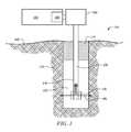
- FIG. 1is a partial cutaway view of an operating environment of a flow-back control system
- FIG. 2is a schematic illustration of a wellbore servicing system
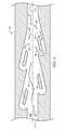
- FIG. 3is a partial cutaway view of an embodiment of a flow-back control system comprising a fluidic diode
- FIG. 4is a partial cutaway view of an embodiment of a flow-back control system comprising a fluidic diode
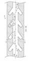
- FIG. 5Ais a partial cutaway view of an embodiment of a flow-back control system comprising a fluidic diode
- FIG. 5Bis a partial cutaway view of an embodiment of a flow-back control system comprising a fluidic diode
- FIG. 6is a partial cutaway view of an embodiment of a flow-back control system comprising a fluidic diode
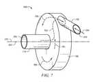
- FIG. 7is a partial cutaway view of an embodiment of a flow-back control system comprising a fluidic diode.
- any use of any form of the terms “connect,” “engage,” “couple,” “attach,” or any other term describing an interaction between elementsis not meant to limit the interaction to direct interaction between the elements and may also include indirect interaction between the elements described.
- the terms “including” and “comprising”are used in an open-ended fashion, and thus should be interpreted to mean “including, but not limited to . . . ”. Reference to up or down will be made for purposes of description with “up,” “upper,” or “upward,” meaning toward the surface of the wellbore and with “down,” “lower,” or “downward,” meaning toward the terminal end of the well, regardless of the wellbore orientation.
- references to in or outwill be made for purposes of description with “in,” “inner,” or “inward” meaning toward the center or central axis of the wellbore and/or an element, and with “out,” “outer,” or “outward” away from the center or central axis of the wellbore and/or an element.
- Reference to “longitudinal,” “longitudinally,” or “axially”means a direction substantially aligned with the main axis of the wellbore, a wellbore tubular, or an element.
- Reference to “radial” or “radially”means a direction substantially aligned with a line from the main axis of the wellbore, a wellbore tubular, and/or an element generally outward.
- Disclosed hereinare embodiments of devices, systems, and methods at least partially controlling the discharge of fluid from a wellbore and/or a component fluidicly connected to the wellbore. Particularly, disclosed herein are one or more embodiments of a flow-back control system, well-bore servicing systems including such a flow-back control system, and methods of utilizing the same.
- FIG. 1schematically illustrates an embodiment of a wellsite 101 .
- a wellbore servicing system 100is deployed at the wellsite 101 and is fluidly coupled to a wellbore 120 .
- the wellbore 120penetrates a subterranean formation 130 , for example, for the purpose of recovering hydrocarbons, storing hydrocarbons, disposing of carbon dioxide, or the like.
- the wellbore 120may be drilled into the subterranean formation 130 using any suitable drilling technique.
- a drilling or servicing rigmay be present at the wellsite 101 and may comprise a derrick with a rig floor through which a pipe string 140 (e.g., a casing string, production string, work string, drill string, segmented tubing, coiled tubing, etc., or combinations thereof) may be lowered into the wellbore 120 .
- the drilling or servicing rigmay be conventional and may comprise a motor driven winch and other associated equipment for lowering the pipe string 140 into the wellbore 120 .
- a mobile workover rig, a wellbore servicing unite.g., coiled tubing units, or the like may be used to lower the pipe string 140 into the wellbore 120 .
- the wellbore 120may extend substantially vertically away from the earth's surface 160 over a vertical wellbore portion, or may deviate at any angle from the earth's surface 160 over a deviated or horizontal wellbore portion. Alternatively, portions or substantially all of the wellbore 120 may be vertical, deviated, horizontal, and/or curved. In some instances, a portion of the pipe string 140 may be secured into position within the wellbore 120 in a conventional manner using cement 170 ; alternatively, the pipe string 140 may be partially cemented in wellbore 120 ; alternatively, the pipe string 140 may be uncemented in the wellbore 120 ; alternatively, all or a portion of the pipe string 140 may be secured using one or more packers (e.g.
- the pipe string 140may comprise two or more concentrically positioned strings of pipe (e.g., a first pipe string such as jointed pipe or coiled tubing may be positioned within a second pipe string such as casing cemented within the wellbore).
- a first pipe stringsuch as jointed pipe or coiled tubing may be positioned within a second pipe string such as casing cemented within the wellbore.
- a wellbore servicing apparatus 150configured for one or more wellbore servicing and/or production operations may be integrated within (e.g., in fluid communication with) the pipe string 140 .
- the wellbore servicing apparatus 150may be configured to perform one or more servicing operations, for example, fracturing the formation 130 , hydrajetting and/or perforating casing (when present) and/or the formation 130 , expanding or extending a fluid path through or into the subterranean formation 130 , producing hydrocarbons from the formation 130 , various other servicing operations, or combinations thereof.
- the wellbore servicing apparatus 150may comprise one or more ports, apertures, nozzles, jets, windows, or combinations thereof for the communication of fluid from a flowbore of the pipe string 140 to the subterranean formation 130 or vice versa.
- the wellbore servicing apparatus 150may be selectively configurable to provide a route of fluid communication between the wellbore servicing apparatus 150 and the wellbore 120 , the subterranean formation 130 , or combinations thereof.
- the wellbore servicing apparatus 150may be configurable for the performance of multiple servicing operations.
- additional downhole toolsfor example, one or more isolation devices (for example, a packer, such as a swellable or mechanical packer), may be included within and/or integrated within the wellbore servicing apparatus 150 and/or the pipe string 140 , for example a packer located above and/or below wellbore servicing apparatus 150 .
- isolation devicesfor example, a packer, such as a swellable or mechanical packer
- the wellbore servicing system 100is generally configured to communicate (e.g., introduce) a fluid (e.g., a wellbore servicing fluid) into wellbore 120 , for example, at a rate and pressure suitable for the performance of a desired wellbore servicing operation.
- a fluide.g., a wellbore servicing fluid
- the wellbore servicing system 100comprises at least one wellbore servicing system equipment component.
- FIG. 2an embodiment of the wellbore servicing system 100 is illustrated. In the embodiment of FIG.
- the wellbore servicing system 100may comprise a fluid treatment system 210 , a water source 220 , one or more storage vessels (such as storage vessels 230 , 201 , 211 , and 221 ), a blender 240 , a wellbore servicing manifold 250 , one or more high pressure pumps 270 , or combinations thereof.
- the fluid treatment system 210may obtain water, either directly or indirectly, from the water source 220 .
- Water from the fluid treatment system 210may be introduced, either directly or indirectly, into the blender 240 where the water is mixed with various other components and/or additives to form the wellbore servicing fluid or a component thereof (e.g., a concentrated wellbore servicing fluid component).
- the wellbore servicing system 100may be fluidicly connected to a wellhead 180 , and the wellhead 180 may be connected to the pipe string 140 .
- the pipe string 140may comprise a casing string, production string, work string, drill string, a segmented tubing string, a coiled tubing string, a liner, or any combinations thereof.
- the pipe string 140may extend from the earth's surface 160 downward within the wellbore 120 to a predetermined or desirable depth, for example, such that the wellbore servicing apparatus 150 is positioned substantially proximate to a portion of the subterranean formation 130 to be serviced (e.g., into which a fracture is to be introduced) and/or produced.
- a flow path formed by a plurality of fluidicly coupled conduitsmay extend through at least a portion of the wellbore servicing system 100 , for example, thereby providing a route of fluid communication through the wellbore servicing system 100 or a portion thereof.
- the flow path 195may extend from the wellbore servicing system 100 to the wellhead 180 , through the pipe string 140 , into the wellbore 120 , into the subterranean formation 130 , vice-versa (e.g., flow in either direction into or out of the wellbore), or combinations thereof.
- flow paths 195 described herein or a similar flow pathmay include various configurations of piping, tubing, etc. that are fluidly connected to each other and/or to one or more components of the wellbore servicing system 100 (e.g., pumps, tanks, trailers, manifolds, mixers/blenders, etc.), for example, via flanges, collars, welds, pipe tees, elbows, and the like.
- components of the wellbore servicing system 100e.g., pumps, tanks, trailers, manifolds, mixers/blenders, etc.
- the wellbore servicing system 100further comprises a flow-back control system 200 .
- the flow-back control system 200is incorporated within the wellbore servicing system 100 such that a fluid communicated from the wellbore servicing system 100 (or one or more components thereof) to the wellhead 180 , alternatively, through the pipe sting 140 , alternatively, into the wellbore 120 , alternatively, to/into the subterranean formation 130 , will be communicated via the flow-back control system.
- the flow-back control system 200may be incorporated and/or integrated within the flow path 195 . While the embodiments of FIGS.
- FIG 1 and 2illustrate a single flow-back system 200 incorporated/integrated within the flow path 195 at a location between the wellbore servicing manifold 250 and the wellhead 180 , this disclosure should not be construed as so-limited.
- the flow-back control system 200may be incorporated/integrated within the flow path 195 at any suitable location.
- the flow-back control system 200may be incorporated at another location within the wellbore servicing system 100 , alternatively, the flow-back control system 200 may be located at and/or within (e.g., incorporated within) the wellhead 180 (e.g., as a part of the “Christmas tree” assembly), alternatively, within (e.g., integrated within) the pipe string 140 , alternatively, at or within the wellbore servicing apparatus 150 .
- multiple flow-back control systemsmay be incorporated/integrated within the flow path 195 at multiple locations.
- the protection afforded by the flow-back control system 200may be at least partially dependent upon the location at which the flow-back control system 200 is integrated within the flow path 195 .
- the flow-back control system 200may be generally configured to allow fluid communication therethrough at a first, relatively higher flow-rate in a first direction and to allow fluid communication therethrough at a second, relatively lower flow-rate in a second, typically opposite direction.
- the first direction of flowmay generally be characterized as toward/into the wellbore 120 or subterranean formation 130 (e.g., injecting or pumping into the wellbore/formation) and the second direction of flow may generally be characterized as away from/out of the wellbore 120 or subterranean formation 130 (e.g., producing from the formation to the surface).
- the flow-back control systemmay be configured to allow a fluid (e.g., a wellbore servicing fluid) to be communicated from a relatively upstream position along the flow path 195 (e.g., the wellbore servicing system 100 or a component thereof) in the direction of a relatively downstream position along the flow path 195 (e.g., the wellhead 180 , the pipe string 140 , the wellbore 120 and/or subterranean formation 130 ) at a relatively low flow restriction in comparison to flow in the opposite direction (e.g., at a substantially uninhibited rate in comparison to flow through the flow path 195 in the absence of the flow-back control system 200 ; in other words, the flow-back control system does not choke off or restrict normal flow through the flow path in the first direction).
- a fluide.g., a wellbore servicing fluid
- flow through the flow-back control system in a first, non-restricted (or non-metered) directionmay be at least about 40 barrels per minute (BPM), alternatively, at least about 50 BPM, alternatively, at least about 60 BPM, alternatively, at least about 70 BMP, alternatively, at least about 80 BPM, alternatively, at least about 90 BPM, alternatively, at least about 100 BPM, alternatively, at least about 120 BPM, alternatively, at least about 140 BPM, alternatively, at least about 160 BPM, alternatively, at least about 180 BPM, alternatively, at least about 200 BPM.
- BPMbarrels per minute
- the flow-back control system 200may be configured in a second, restricted (or metered) direction to allow a fluid to be communicated from the relatively downstream position along the flow path 195 (e.g., the wellhead 180 , the pipe string 140 , the wellbore 120 and/or subterranean formation 130 ) in the direction of the upstream position along the flowpath 195 (e.g., the wellbore servicing system 100 or a component thereof) at a relatively high flow-rate restriction (i.e., at a controlled rate), for example, not more than about 100 BPM, alternatively, not more than about 90 BPM, alternatively, not more than about 80 BPM, alternatively, not more than about 70 BPM, alternatively, not more than about 60 BPM, alternatively, not more than about 50 BPM, alternatively, not more than about 40 BPM, alternatively, not more than about 30 BPM, alternatively, not more than about 25 BPM, alternatively, not more than about 20 BPM, alternatively, not more than about 15 BPM, alternative
- the flow-back control system 200may be configured to be incorporated and/or integrated within the flow path 195 .
- the flow-back control system 200may comprise a suitable connection to the wellbore servicing system 100 (or a wellbore servicing equipment component thereof), to the wellhead 180 , to the pipe string 140 , to any fluid conduit extending therebetween, or combinations thereof.
- the flow-back control system 200may comprise internally or externally threaded surfaces, suitable for connection via a threaded interface.
- the flow-back control system 200may comprise one or more flanges, suitable for connection via a flanged connection. Additional or alternative suitable connections will be known to those of skill in the art upon viewing this disclosure.
- the flow-back control system 200may comprise (e.g., be formed from) a suitable material.
- a suitable materialmay be characterized as relatively resilient when exposed to abrasion. Examples of suitable materials include, but are not limited to, metals (such as titanium), metallic alloys (such as carbon steel, tungsten carbide, hardened steel, and stainless steel), ceramics, polymers (such as polyurethane) or combinations thereof.
- the flow-back control system 200may comprise a fluidic diode.
- the term “fluidic diode”may refer to a component generally defining a flowpath which exhibits a relatively low restriction to fluid movement (e.g., flow) therethrough in one direction (e.g., the first or “forward” direction) and a relatively high restriction to fluid movement (e.g., flow) therethrough in the opposite direction (e.g., a second or “reverse” direction). Any reference herein to fluid flow in either a “forward” or a “reverse” is solely for the purpose of reference and should not be construed as limiting the flow-back control system 200 or a fluidic diode thereof to any particularly orientation.
- a fluidic diodemay be configured so as to not prevent (e.g., cease, altogether as is typically provided for example by a check-valve configuration such as a flapper-type safety valve) fluid movement in any particular direction, but rather, may be configured so as to provide variable resistance to fluid movement, dependent upon the direction of the fluid movement.
- the flow path defined by a fluidic diodemay be characterized as comprising two points of entry into that flow path, for example, a high-resistance entry and a low-resistance entry.
- fluid movement from the low-resistance entry in the direction of the high-resistance entrymay comprise forward flow, as referenced herein (e.g., low-resistance flow); conversely, fluid movement from the high-resistance entry in the direction of the low-resistance entry may comprise reverse flow, as referenced herein (e.g., high-resistance flow).
- the flow-back control system 200may comprise two or more fluidic diodes, for example, three, four, five, six, seven, eight, nine, ten, eleven, twelve, or more fluid diodes, for example, arranged in parallel and/or in series and may be spaced in close proximity (e.g., immediately adjacent such that flow exiting one fluidic diode is fed directly into another fluidic diode) and/or may be distributed at distances or intervals along the flow path 195 .
- the multiple fluidic diodesmay be fluidicly coupled together (e.g., manifolded), for example, so as to provide for a desired total flow rate in either the first and/or second direction.
- a plurality of fluidic diodesmay be coupled in series, in parallel, or combinations thereof to achieve a desired flow characteristic there through.
- the fluidic diode(s)may be configured such that the maximum flow-rate allowed therethrough in the reverse direction (at a given fluid pressure) is not more than 90% of the maximum flow-rate allowed in the forward direction (at the same fluid pressure), alternatively, not more than 80%, alternatively, not more than 70%, alternatively, not more than 60%, alternatively, not more than 50%, alternatively, not more than 40%, alternatively, not more than 30%, alternatively, not more than 20%, alternatively, not more than 10% of the maximum flow-rate allowed in the forward direction.
- flow-back control systems 200particularly, one or more embodiments of fluidic diodes which may form a flow path through such fluid control systems, are disclosed herein.
- the suitability of a given type and/or configuration of flow-back control system 200 and/or fluidic diodemay depend upon one or more factors including, but not necessarily limited to, the position/location at which the flow-back control system 200 is incorporated within the flow path 195 , the intended flow rate at which a fluid may be communicated via the flow-back control system 200 (in one or both directions), the composition/type of fluid(s) intended to be communicated via the flow-back control system 200 (e.g., abrasive fluids, cementitious fluids, solids-laden fluids, etc.), the rheology of the fluid(s) intended to be communicated via the flow-back control system 200 , or combinations thereof.
- the composition/type of fluid(s) intended to be communicated via the flow-back control system 200e.g., abrasive fluids, cement
- a flow-back control systemcomprises one or more fluidic diodes having a flow path substantially the same as, the same as, about equal to, equal to, and/or defined by the shape, characteristics, layout, and/or orientation of the flow path shown in any one of FIGS. 3-7 .
- the fluidic diodecomprises a generally axial flow path (e.g., a primary flow path that extends generally axially) contained or sealed within a structural support or body.
- a generally axial flow pathe.g., a primary flow path that extends generally axially
- such axially-extending fluidic diodesmay comprise an inner flow profile defined within a body (e.g., a tubular member, a pipe, housing, or the like).
- such axially-extending fluidic diodesmay comprise a series of grooves (e.g., an inlayed pattern) within one or more substantially flat surfaces of a body that may be covered by a cap or top plate to define a sealed flow path.
- a fluidic diode containing one or more flat surfacesmay be further contained within a body (e.g., mandrel, housing, tubular or the like) of any suitable shape (e.g., cylindrical, rectangular, etc.) to facilitate make-up into a wellbore tubular string, the wellbore servicing system 100 , or otherwise to facilitate incorporation into the flow path 195 .
- a bodye.g., mandrel, housing, tubular or the like
- any suitable shapee.g., cylindrical, rectangular, etc.
- the flow path primarily defined by the fluidic diodecomprises one or more changes in direction and, as such, the flow-back system 200 may comprise a separate and/or dedicated structure.
- the flow-back control system 200may have suitable connectors (e.g., flanges, threaded connections, etc.) located at each end of the body to allow incorporation into the flow path 195 .
- the fluidic diodesgenerally define a flow path 195 a at least partially extending therethrough.
- the flow-back control system 200is configured such that fluid movement in the forward direction (denoted by flow-arrow 202 ) will result in a relatively low resistance to flow and such that fluid movement in the reverse direction (denoted by flow-arrow 204 ) will result in a relatively high resistance to flow.
- the fluidic diodegenerally comprises a nozzle-like configuration, for example a nozzle having a trapezoidal or conical cross-section wherein the larger end of the trapezoid or cone is adjacent to and/or defines the low-resistance entry 205 and the smaller end of the trapezoid or cone is adjacent to and/or defines the high-resistance entry 210 .
- the nozzleis centered along a central longitudinal axis 215 of flow path 195 a and having an angle ⁇ defining the conical or trapezoidal cross section.
- the flow path 195 agradually narrows through a nozzle or orifice 305 in the flow path 195 a .
- the flow path 195 anarrows to the orifice 305 substantially more abruptly.
- the fluidic diode if FIG. 3may be configured such that fluid movement through the orifice in the forward direction results in a coefficient of discharge through the orifice 305 that is different from the coefficient of discharge resultant from fluid movement through the orifice 305 in the reverse direction. As such, fluid is able to the move through the fluidic diode of FIG.
- the fluidic diodegenerally comprises a Tesla-style fluid conduit. Tesla-style conduits are disclosed in U.S. Pat. No. 1,329,559 to Tesla, which is incorporated herein in its entirety.
- the flow path 195 a defined by the fluidic diodegenerally comprises various enlargements, recesses, projections, baffles, or buckets, for example, island-like projections 410 that are surrounded on all sides by flow path 195 a .
- flow arrow 403e.g., substantially parallel and co-axial to a central longitudinal axis 215 of the fluidic diode 200 and/or flow path 195 a
- flow path designated by flow arrows 405e.g., not substantially parallel and co-axial to a central longitudinal axis 215 of the fluidic diode 200 and/or flow path 195 a , and including areas of flow substantially perpendicular and/or reverse to flow arrow 204 ).
- flow path demonstrated by flow arrow 403e.g., forward fluid movement
- flow path demonstrated by flow arrows 405is relatively intermittent and broken, being successively accelerated in different directions (e.g., caused to move in one or more directions which may be at least partially opposed to the reverse flow), for example, as a result of the interaction with the multiple island-like projections 405 .
- fluid movement in the reverse directionmay cause the formation of various eddies, cross-currents, and/or counter-currents that interfere with, and substantially restrict, fluid movement in the reverse direction.
- fluidis able to move through the fluidic diode of FIG. 4 in the forward direction with a flow restriction that is substantially lower than the flow restriction at which fluid is able to move through the fluidic diode in the reverse direction.
- the fluidic diodeseach generally comprise a primary flow path 510 (e.g., substantially parallel and co-axial to a central longitudinal axis 215 of the fluidic diode 200 and/or flow path 510 ) and further comprising a plurality of secondary flow paths 512 generally extending away from the primary flow path 510 before ceasing (e.g., “dead-ending”), for example, generally extending away from the primary flow path 510 at an angle ⁇ in relation to central longitudinal axis 215 .
- a primary flow path 510e.g., substantially parallel and co-axial to a central longitudinal axis 215 of the fluidic diode 200 and/or flow path 510
- a plurality of secondary flow paths 512generally extending away from the primary flow path 510 before ceasing (e.g., “dead-ending”), for example, generally extending away from the primary flow path 510 at an angle ⁇ in relation to central longitudinal axis 215 .
- the plurality of secondary flow paths 512may comprise a plurality of pyramidal or trapezoidal, dead-end flow paths forming a notched or saw-tooth like configuration.
- the plurality of secondary flow paths 512may comprise a plurality of cylindrical, dead-end flow paths forming an alveoli-like configuration.
- 5A and 5Bmay be configured such that fluid movement in the forward direction generally and/or substantially follows a flow path designated by flow arrows 503 (e.g., substantially parallel and co-axial to a central longitudinal axis 215 of the fluidic diode 200 and/or flow path 510 ) and such that fluid movement in the reverse direction generally and/or substantially follows a flow path designated by flow arrows 505 (e.g., not substantially parallel and co-axial to a central longitudinal axis 215 of the fluidic diode 200 and/or flow path 510 , and including areas of flow substantially perpendicular and/or reverse to flow arrow 204 ).
- flow arrows 503e.g., substantially parallel and co-axial to a central longitudinal axis 215 of the fluidic diode 200 and/or flow path 510
- flow path designated by flow arrows 505e.g., not substantially parallel and co-axial to a central longitudinal axis 215 of the fluidic diode 200 and/or flow
- flow path demonstrated by flow arrows 503are relatively smooth and continuous
- flow path demonstrated by flow arrows 505is relatively intermittent and broken, being successively accelerated in different directions (e.g., caused to move in one or more directions which may be at least partially opposed to the reverse flow), for example, as a result of some portion of the flow in the reverse direction entering the secondary flow paths 512 and, because such secondary flow paths are “dead ends,” the fluid within the secondary flow paths 512 being returned to the primary flow path 510 in a direction at least partially against the direction of fluid movement.
- flow arrows 503e.g., forward fluid movement
- flow path demonstrated by flow arrows 505is relatively intermittent and broken, being successively accelerated in different directions (e.g., caused to move in one or more directions which may be at least partially opposed to the reverse flow), for example, as a result of some portion of the flow in the reverse direction entering the secondary flow paths 512 and, because such secondary flow paths are “dead ends,” the fluid within the secondary flow paths 512
- fluid movement in the reverse directionmay cause the formation of various eddies, cross-currents, and/or counter-currents that interfere with, and substantially restrict, fluid movement in the reverse direction.
- fluidis able to move through the fluidic diodes of FIGS. 5A and 5B in the forward direction with a flow restriction that is substantially lower than the flow restriction at which fluid is able to move through the fluidic diode in the reverse direction.
- the fluidic diodegenerally comprises a module 610 , generally disposed approximately within the center (e.g., co-axial with central longitudinal axis 215 ) of at least a portion of the flow path 195 a and extending substantially toward a nozzle or orifice 612 (e.g., a narrowing of the flow path 195 a ).
- Nozzle or orifice 612may be conical or trapezoidal as discussed with respect to FIG. 3 .
- the module 610comprises one or more furrows or valleys 614 facing (e.g., opening toward) the nozzle or orifice 612 .
- the module 610may be described as having a crown of trident like cross section having three peaks (a central peak with lesser, minor peaks on either side thereof defining concave surfaces or furrows 615 at an angle ⁇ away from the central longitudinal axis 215 ).
- the fluidic diode of FIG. 6may be configured such that fluid movement in the forward direction generally and/or substantially follows a flow path designated by flow arrows 603 and such that fluid movement in the reverse direction generally and/or substantially follows a flow path designated by flow arrows 605 .
- flow path demonstrated by flow arrows 603e.g., forward fluid movement
- flow path demonstrated by flow arrows 605e.g., reverse fluid movement
- fluid movement in the reverse directionmay cause the formation of various eddies, cross-currents, and/or counter-currents that interfere with, and substantially restrict, fluid movement in the reverse direction.
- fluidis able to move through the fluidic diode of FIG. 6 in the forward direction with a flow restriction that is substantially lower than the flow restriction at which fluid is able to move through the fluidic diode in the reverse direction.
- the fluidic diodegenerally comprises a vortex chamber or Zobel diode configuration.
- the flow-back control system 200generally comprises a cylindrical chamber 700 , an axial port 710 (e.g., a fluid inlet or outlet), and a radial port 720 (e.g., a fluid inlet or outlet).
- a axial port 710e.g., a fluid inlet or outlet
- a radial port 720e.g., a fluid inlet or outlet
- the axial port 710is generally positioned so as to introduce a fluid into (alternatively, to receive a fluid from) approximately the center (e.g., co-axial with respect to the central longitudinal axis 215 of the cylinder) of the cylindrical chamber 700 .
- the radial port 720is generally positioned so as to introduce a fluid into (alternatively, to receive a fluid from) the cylindrical chamber 700 at a position radially removed from the approximate center of the cylindrical chamber 700 .
- the axial port 710 and radial port 720define flow paths that are about perpendicular to one another and spaced a distance apart (defined by the radius of cylindrical chamber 700 ) relative to central longitudinal axis 215 .
- the radial port 720is positioned along the circumference of the cylindrical chamber 700 and is generally oriented tangentially to the outer surface of cylindrical chamber 700 .
- the fluidic diode of FIG. 7may be configured such that fluid movement in the forward direction generally and/or substantially follows a flow path designated by flow arrow 703 and such that fluid movement in the reverse direction generally and/or substantially follows a flow path designated by flow arrows 705 .
- the fluidic diode of FIG. 7may be configured such that, as demonstrated by flow arrow 703 (e.g., forward fluid movement), fluid that enters the cylindrical chamber 700 via the axial port 710 (e.g., the low-restriction entry 205 ) may flow (e.g., directly) from the axial port 710 and out of the radial port 720 .
- the fluidic diode of FIG. 7may also be configured such that, as demonstrated by flow arrows 705 (e.g., reverse fluid movement), fluid that enters the cylindrical chamber 700 via the radial port 720 (e.g., the high-restriction entry 210 ) will circulate (e.g., forming a vortex) within the cylindrical chamber 700 and does not flow (e.g., directly) out of the axial port 710 .
- fluidis able to move through the fluidic diode of FIG. 7 in the forward direction with a flow restriction that is substantially lower than the flow restriction at which fluid is able to move through the fluidic diode in the reverse direction.
- the type and/or configuration of a given fluidic diodemay bear upon the position and/or location at which the flow-back control system 200 may incorporated within the flow path 195 .
- the fluidic diodemay be incorporated/integrated within a tubular member or other similar axial member or body (e.g., defining the flow path 195 a of the fluidic diode) as disclosed with reference to FIGS.
- the flow-back control system 200may be suitably incorporated within the flow path 195 at a location within the wellbore servicing system 100 , alternatively, between the wellbore servicing manifold 250 and the wellhead 180 , alternatively, at and/or within (e.g., incorporated within) the wellhead 180 (e.g., as a part of the “Christmas tree” assembly), alternatively, within (e.g., integrated within) the pipe string 140 .
- the flow-back system 200comprises a separate and/or dedicated structure as disclosed with reference to FIG. 7
- the flow-back control system 200may be incorporated within the flow path 195 at a location within the wellbore servicing system 100 , alternatively, between the wellbore servicing manifold 250 and the wellhead 180 .
- one or more a flow-back control systemsmay be employed in the performance of a wellbore servicing method.
- the wellbore servicing methodmay generally comprise the steps of providing a wellbore servicing system (for example, the wellbore servicing system 100 disclosed herein), providing a flow path comprising a flow-back control system (e.g., the flow-back control system 200 disclosed herein) between the wellbore servicing system 100 and a wellbore (e.g., wellbore 120 ), and introducing a fluid into the wellbore 120 via the flow path.
- the wellbore servicing methodmay further comprise allowing fluid to flow from the wellbore at a controlled rate.
- providing the wellbore servicing systemmay comprise transporting one or more wellbore servicing equipment components, for example, as disclosed herein with respect to FIGS. 1 and 2 , to a wellsite 101 .
- the wellsite 101comprises a wellbore 120 penetrating a subterranean formation 130 .
- the wellboremay be at any suitable stage.
- the wellbore 120may be newly drilled, alternatively, newly completed, alternatively, previously completed and produced, or the like.
- the wellbore servicing equipment components that are brought to the wellsite 101may vary dependent upon the wellbore servicing operation that is intended to be performed.
- providing a flow path (for example, flow path 195 disclosed herein) comprising a flow-back control system 200 between the wellbore servicing system 100 and the wellbore 120may comprise assembling the wellbore servicing system 100 , coupling the wellbore servicing system 100 to the wellbore 120 , providing a pipe string within the wellbore, or combinations thereof.
- one or more wellbore servicing equipment componentsmay be assembled (e.g., fluidicly coupled) so as to form the wellbore servicing system 100 , for example, as illustrated in FIG. 2 .
- the wellbore servicing system 100may be fluidicly coupled to the wellbore.
- the manifold 250may be fluidicly coupled to the wellhead 180 .
- a pipe string(such as pipe string 140 ) may be run into the wellbore to a predetermined depth; alternatively, the pipe string 140 may already be present within the wellbore 120 .
- providing the flow path 195 comprising a flow-back control system 200 between the wellbore servicing system 100 and the wellbore 120may also comprise incorporating the flow-back control system 200 within the flow path 195 .
- the flow-back control system 200may be fluidicly connected (e.g., fluidicly in-line with flow path 195 ) during assembly of the wellbore servicing system 100 and/or as a part of coupling the wellbore servicing system 100 to the wellbore 120 .
- the flow-back control system 200may be integrated within one or more components present at the wellsite 101 .
- the flow-back control system 200may be integrated/incorporated within (e.g., a part of) one or more wellbore servicing equipment components (e.g., of the wellbore servicing system 100 , for example as part of the manifold 250 ), within the wellhead 180 , within the pipe string 140 , within the wellbore tool 150 , or combinations thereof.
- a fluidmay be introduced in to the wellbore via the flow path 195 .
- the fluidmay comprise a wellbore servicing fluid.
- a suitable wellbore servicing fluidinclude, but are not limited to, a fracturing fluid, a perforating or hydrajetting fluid, an acidizing fluid, the like, or combinations thereof.
- the wellbore servicing fluidmay comprise a composite fluid, for example, having two or more fluid components which may be communicated into the wellbore separately (e.g., via two or more different flow paths).
- the wellbore servicing fluidmay be communicated at a suitable rate and pressure for a suitable duration.
- the wellbore servicing fluidmay be communicated at a rate and/or pressure sufficient to initiate or extend a fluid pathway (e.g., a perforation or fracture) within the subterranean formation 130 and/or a zone thereof.
- the fluide.g., the wellbore servicing fluid
- the wellbore servicing fluidmay be communicated via the flow-back control system 200 .
- the wellbore servicing fluidmay enter the flow-back control system 200 (e.g., a fluidic diode) via a low resistance entry and exit the flow-back control system 200 via a high resistance entry.
- the wellbore servicing fluidmay experience relatively little resistance to flow when communicated into the wellbore (e.g., in a forward direction).
- the flow-back control system 200is configured to allow fluid communication in both directions (e.g., as opposed to a check valve, which operates to allow fluid communication in only one direction), fluid may be flowed in both directions during the performance of the wellbore servicing operation.
- the wellbore servicing fluidmay be delivered into the wellbore at a relatively high rate (e.g., as may be necessary during a fracturing or perforating operation) and returned from the wellbore (e.g., reverse-circulated, as may be necessitated during some servicing operations, for example for fluid recovery, pressure bleed-off, etc.) at a relatively low rate.
- the wellbore servicing methodfurther comprises allowing a fluid to flow from the wellbore 120 at a controlled rate.
- control of the wellboremay be lost, for example, during the performance of a wellbore servicing operation, after the cessation of a servicing operation, or at some other time.
- Control of the wellboremay be lost or compromised for a number of reasons.
- control of a wellboremay be compromised as a result of equipment failure (e.g., a broken or ruptured flow conduit, a non-functioning valve, or the like), operator error, or combinations thereof.
- any such flow of fluids out of the wellboremay occur at a controlled rate, alternatively, at a substantially controlled rate.
- fluid escaping from the wellbore 120e.g., from the wellhead 180
- the fluid flowing out of the wellboremay enter the flow-back control system 200 (e.g., a fluidic diode) via the high resistance entry and exit the flow-back control apparatus via the low-resistance entry.
- the wellbore servicing fluidmay experience relatively high resistance to flow when communicated out of the wellbore.
- the flow-back control apparatus 200may allow such fluids to be communicated at a rate sufficiently low so as to allow the wellbore to again be brought under control (e.g., for well control to be re-established).
- the area surrounding the wellboree.g., the wellsite
- the wellsitemay remain safe, thereby allowing personnel to manually bring the wellbore under control (e.g., using a manually operated valve located at the wellhead 180 ).
- a flow-back control systemsuch as the flow-back control system 200 disclosed herein, and/or methods of utilizing the same, may be advantageously employed, for example, in the performance of a wellbore servicing operation.
- the utilization of such a flow-back control systemmay allow fluid movement, both into and out of a wellbore, at an appropriate rate.
- the flow-back control systemmay be configured so as to allow fluid to be communicated into a wellbore at a rate sufficiently high to stimulate e.g., fracture or perforate) a subterranean formation and to allow fluid to be communicated out of the wellbore at a rate sufficiently low to provide improved safety (e.g., from unexpected fluid discharges) to operators and/or personnel present in the area around the wellbore.
- check valveshave been conventionally employed at and/or near the wellhead, for example, to prevent the unintended escape of fluids.
- check valvesare configured to permit flow therethrough in only a first direction while prohibiting entirely flow therethrough in a second direction.
- a check valvewould not control the escape of fluids during a point during an operation when such check valve was deactivated (e.g., during reverse circulation or reverse-flowing).
- check valvesgenerally utilize moving parts and, as such, exposure to high flow-rates of relatively abrasive fluids (e.g., wellbore servicing fluids) may damage and/or render inoperable such check valves.
- the flow-back control systemmay comprise relatively few (for example, none) moving parts and, as such, may be far less susceptible to failure or degradation. Also, by allowing some fluid flow in the reverse direction (as opposed to complete shut-off of fluid flow in the reverse direction by a check valve), undesirably high pressure spikes may be lessened or avoided by the use of the flow-back control systems comprising fluidic diodes as disclosed herein, further protecting personnel and equipment from injury or damage that may occur from over-pressurization of equipment.
- flow-back control systemscomprising fluidic diodes as disclosed herein, while not completely shutting off reverse flow, may reduce/restrict reverse flow for a sufficient time and/or reduction in flow rate or pressure to allow other safety systems to be activated and/or to function (e.g., an additional amount of time for a blow-out preventer to be activated and/or fully close).
- a first embodimentwhich is a wellbore servicing system disposed at a wellbore, the wellbore servicing system comprising:
- At least one wellbore servicing equipment componentwherein a flow path extends from the wellbore servicing system component into the wellbore
- a flow-back control systemwherein the flow-back control system is disposed along the flow path, and wherein the flow-back control system is configured to allow fluid communication via the flow path in a first direction at not less than a first rate and to allow fluid communication via the flow path in a second direction at not more than a second rate, wherein the first rate is greater than the second rate.
- a second embodimentwhich is the wellbore servicing system of the first embodiment, wherein the wellbore servicing equipment component comprises a mixer, a pump, a wellbore services manifold, a storage vessel, or combinations thereof.
- a third embodimentwhich is the wellbore servicing system of one of the first through the second embodiments, wherein the first direction is generally into the wellbore.
- a fourth embodimentwhich is the wellbore servicing system of one of the first through the third embodiments, wherein the second direction is generally out of the wellbore.
- a fifth embodimentwhich is the wellbore servicing system of one of the first through the fourth embodiments, wherein the first rate comprises a relatively high rate and the second rate comprises a relatively low rate.
- a sixth embodimentwhich is the wellbore servicing system of one of the first through the fifth embodiments, wherein the flow-back control system comprises a fluidic diode.
- a seventh embodimentwhich is the wellbore servicing system of the sixth embodiment, wherein the fluidic diode comprises a relatively high-resistance entry and a relatively low-resistance entry.
- An eighth embodimentwhich is the wellbore servicing system of one of the sixth through the seventh embodiments, wherein the fluidic diode generally defines a diode flow path, wherein the diode flow path is in fluid communication with the flow path.
- a ninth embodimentwhich is the wellbore servicing system of the eighth embodiment, wherein the diode flow path comprises a primary diode flowpath and one or more secondary diode flow paths, wherein flow in the first direction is along the primary diode flowpath and flow in the second direction is along the one or more secondary diode flow paths.
- a tenth embodimentwhich is the wellbore servicing system of the eighth embodiment, wherein the diode flow path comprises a plurality of island-like projections or more protrusions.
- An eleventh embodimentwhich is the wellbore servicing system of the eighth embodiment, wherein the diode flow path comprises a nozzle.
- a twelfth embodimentwhich is the wellbore servicing system of the eighth embodiment, wherein the diode flow path comprises a vortex.
- a thirteenth embodimentwhich is the wellbore servicing system of one of the first through the twelfth embodiments, wherein the flow-back control system comprises no moving parts.
- a fourteenth embodimentwhich is the wellbore servicing system of one of the sixth through the thirteenth embodiments, wherein the fluidic diode has a flow path as shown in any one of FIGS. 3-7 .
- a fifteenth embodimentwhich is the wellbore servicing system of one of the first through the fourteenth embodiments, wherein the first rate is at least 1.5, 2, 2.5, 3, 3.5, 4, 4.5, 5, 6, 7, 8, 9, 10, or 12 times greater than the second flow rate.
- a sixteenth embodimentwhich is a wellbore servicing method comprising:
- a flow-back control systemcomprising a fluidic diode is disposed along the flow path at the surface of the subterranean formation
- a seventeenth embodimentwhich is the method of the sixteenth embodiment, further comprising allowing a fluid to flow through at least a portion of the flow path in a second direction, wherein fluid flowing through the flow path in the second direction is communicated at a rate of not more than a second rate.
- An eighteenth embodimentwhich is the method of the seventeenth embodiment, wherein the first rate comprises a relatively high rate and the second rate comprises a relatively low rate.
- a nineteenth embodimentwhich is the method of one of the seventeenth through the eighteenth embodiments, wherein the first direction is generally into the wellbore and the second direction is generally out of the wellbore.
- a twentieth embodimentwhich is the method of one of the seventeenth through the nineteenth embodiments, wherein movement of fluid through the fluidic diode in the first direction may be characterized as relatively low-resistance.
- a twenty-first embodimentwhich is the method of one of the seventeenth through the twentieth embodiments, wherein movement of fluid through the fluidic diode in the second direction may be characterized as relatively high-resistance.
- a twenty-second embodimentwhich is the method of one of the seventeenth through the twenty-first embodiments, wherein movement of fluid through the fluidic diode in the first direction may be characterized as relatively continuous and uninterrupted.
- a twenty-third embodimentwhich is the method of one of the seventeenth through the twenty-second embodiments, wherein movement of fluid through the fluidic diode in the second direction may be characterized as contributing to the formation of eddies, cross-currents, counter-currents, or combinations thereof, wherein the eddies, cross-currents, counter-currents, or combinations thereof interfere with fluid movement in the second direction.
- RR l +k*(R u ⁇ R l ), wherein k is a variable ranging from 1 percent to 100 percent with a 1 percent increment, i.e., k is 1 percent, 2 percent, 3 percent, 4 percent, 5 percent, . . . , 50 percent, 51 percent, 52 percent, . . . , 95 percent, 96 percent, 97 percent, 98 percent, 99 percent, or 100 percent.
- any numerical range defined by two R numbers as defined in the aboveis also specifically disclosed.
Landscapes
- Engineering & Computer Science (AREA)
- Life Sciences & Earth Sciences (AREA)
- Geology (AREA)
- Mining & Mineral Resources (AREA)
- Physics & Mathematics (AREA)
- Environmental & Geological Engineering (AREA)
- Fluid Mechanics (AREA)
- General Life Sciences & Earth Sciences (AREA)
- Geochemistry & Mineralogy (AREA)
- Mechanical Engineering (AREA)
- Other Liquid Machine Or Engine Such As Wave Power Use (AREA)
- Jet Pumps And Other Pumps (AREA)
Abstract
Description
Not applicable.
Not applicable.
Not applicable.
Wellbores are sometimes drilled into subterranean formations that contain hydrocarbons to allow for the recovery of the hydrocarbons. Once the wellbore has been drilled, various servicing and/or completion operations may be performed to configure the wellbore for the production of hydrocarbons. During drilling operations, servicing operations, completion operations, or combinations thereof, large volumes of often very high pressure fluids may be present within the wellbore and/or subterranean formation and/or within various flowlines connecting wellbore servicing equipment components to the wellbore. As such, the opportunity for an uncontrolled discharge of fluids, whether as a result of operator error, equipment failure, or some other unforeseen circumstance, exists in a wellsite environment. The uncontrolled discharge of fluids from the wellbore, whether directly from the wellhead or from a flowline in connection therewith, poses substantial safety risks to personnel. As such, there is a need for dealing with such uncontrolled fluid discharges.
Disclosed herein is a wellbore servicing system disposed at a wellbore, the wellbore servicing system comprising at least one wellbore servicing equipment component, wherein a flow path extends from the wellbore servicing system component into the wellbore, and a flow-back control system, wherein the flow-back control system is disposed along the flow path, and wherein the flow-back control system is configured to allow fluid communication via the flow path in a first direction at not less than a first rate and to allow fluid communication via the flow path in a second direction at not more than a second rate, wherein the first rate is greater than the second rate.
Also disclosed herein is a wellbore servicing method comprising providing a flow path between a wellbore servicing system and a wellbore penetrating a subterranean formation, wherein a flow-back control system comprising a fluidic diode is disposed along the flow path at the surface of the subterranean formation, and communicating a fluid via the flow path in a first direction at not less than a first rate.
These and other features will be more clearly understood from the following detailed description taken in conjunction with the accompanying drawings and claims.
For a more complete understanding of the present disclosure and the advantages thereof, reference is now made to the following brief description, taken in connection with the accompanying drawings and detailed description:
In the drawings and description that follow, like parts are typically marked throughout the specification and drawings with the same reference numerals, respectively. The drawing figures are not necessarily to scale. Certain features of the invention may be shown exaggerated in scale or in somewhat schematic form and some details of conventional elements may not be shown in the interest of clarity and conciseness.
Unless otherwise specified, any use of any form of the terms “connect,” “engage,” “couple,” “attach,” or any other term describing an interaction between elements is not meant to limit the interaction to direct interaction between the elements and may also include indirect interaction between the elements described. In the following discussion and in the claims, the terms “including” and “comprising” are used in an open-ended fashion, and thus should be interpreted to mean “including, but not limited to . . . ”. Reference to up or down will be made for purposes of description with “up,” “upper,” or “upward,” meaning toward the surface of the wellbore and with “down,” “lower,” or “downward,” meaning toward the terminal end of the well, regardless of the wellbore orientation. Reference to in or out will be made for purposes of description with “in,” “inner,” or “inward” meaning toward the center or central axis of the wellbore and/or an element, and with “out,” “outer,” or “outward” away from the center or central axis of the wellbore and/or an element. Reference to “longitudinal,” “longitudinally,” or “axially” means a direction substantially aligned with the main axis of the wellbore, a wellbore tubular, or an element. Reference to “radial” or “radially” means a direction substantially aligned with a line from the main axis of the wellbore, a wellbore tubular, and/or an element generally outward. The various characteristics mentioned above, as well as other features and characteristics described in more detail below, will be readily apparent to those skilled in the art with the aid of this disclosure upon reading the following detailed description of the embodiments, and by referring to the accompanying drawings.
Disclosed herein are embodiments of devices, systems, and methods at least partially controlling the discharge of fluid from a wellbore and/or a component fluidicly connected to the wellbore. Particularly, disclosed herein are one or more embodiments of a flow-back control system, well-bore servicing systems including such a flow-back control system, and methods of utilizing the same.
Thewellbore 120 may extend substantially vertically away from the earth'ssurface 160 over a vertical wellbore portion, or may deviate at any angle from the earth'ssurface 160 over a deviated or horizontal wellbore portion. Alternatively, portions or substantially all of thewellbore 120 may be vertical, deviated, horizontal, and/or curved. In some instances, a portion of thepipe string 140 may be secured into position within thewellbore 120 in a conventionalmanner using cement 170; alternatively, thepipe string 140 may be partially cemented inwellbore 120; alternatively, thepipe string 140 may be uncemented in thewellbore 120; alternatively, all or a portion of thepipe string 140 may be secured using one or more packers (e.g. mechanical or swellable packers, such as SWELLPACKER isolation systems, commercially available from Halliburton Energy Services). In an embodiment, thepipe string 140 may comprise two or more concentrically positioned strings of pipe (e.g., a first pipe string such as jointed pipe or coiled tubing may be positioned within a second pipe string such as casing cemented within the wellbore). It is noted that although one or more of the figures may exemplify a given operating environment, the principles of the devices, systems, and methods disclosed may be similarly applicable in other operational environments, such as offshore and/or subsea wellbore applications.
In the embodiment ofFIG. 1 , awellbore servicing apparatus 150 configured for one or more wellbore servicing and/or production operations may be integrated within (e.g., in fluid communication with) thepipe string 140. Thewellbore servicing apparatus 150 may be configured to perform one or more servicing operations, for example, fracturing theformation 130, hydrajetting and/or perforating casing (when present) and/or theformation 130, expanding or extending a fluid path through or into thesubterranean formation 130, producing hydrocarbons from theformation 130, various other servicing operations, or combinations thereof. In an embodiment, thewellbore servicing apparatus 150 may comprise one or more ports, apertures, nozzles, jets, windows, or combinations thereof for the communication of fluid from a flowbore of thepipe string 140 to thesubterranean formation 130 or vice versa. In an embodiment, thewellbore servicing apparatus 150 may be selectively configurable to provide a route of fluid communication between thewellbore servicing apparatus 150 and thewellbore 120, thesubterranean formation 130, or combinations thereof. In an embodiment, thewellbore servicing apparatus 150 may be configurable for the performance of multiple servicing operations. In an embodiment, additional downhole tools, for example, one or more isolation devices (for example, a packer, such as a swellable or mechanical packer), may be included within and/or integrated within thewellbore servicing apparatus 150 and/or thepipe string 140, for example a packer located above and/or belowwellbore servicing apparatus 150.
In an embodiment, thewellbore servicing system 100 is generally configured to communicate (e.g., introduce) a fluid (e.g., a wellbore servicing fluid) intowellbore 120, for example, at a rate and pressure suitable for the performance of a desired wellbore servicing operation. In an embodiment, thewellbore servicing system 100 comprises at least one wellbore servicing system equipment component. Turning toFIG. 2 , an embodiment of thewellbore servicing system 100 is illustrated. In the embodiment ofFIG. 2 , thewellbore servicing system 100 may comprise afluid treatment system 210, awater source 220, one or more storage vessels (such asstorage vessels blender 240, awellbore servicing manifold 250, one or morehigh pressure pumps 270, or combinations thereof. In the embodiment ofFIG. 2 , thefluid treatment system 210 may obtain water, either directly or indirectly, from thewater source 220. Water from thefluid treatment system 210 may be introduced, either directly or indirectly, into theblender 240 where the water is mixed with various other components and/or additives to form the wellbore servicing fluid or a component thereof (e.g., a concentrated wellbore servicing fluid component).
Returning toFIG. 1 , in an embodiment, thewellbore servicing system 100 may be fluidicly connected to awellhead 180, and thewellhead 180 may be connected to thepipe string 140. In various embodiments, thepipe string 140 may comprise a casing string, production string, work string, drill string, a segmented tubing string, a coiled tubing string, a liner, or any combinations thereof. Thepipe string 140 may extend from the earth'ssurface 160 downward within thewellbore 120 to a predetermined or desirable depth, for example, such that thewellbore servicing apparatus 150 is positioned substantially proximate to a portion of thesubterranean formation 130 to be serviced (e.g., into which a fracture is to be introduced) and/or produced.
In an embodiment, for example, in the embodiment ofFIGS. 1 and 2 , a flow path formed by a plurality of fluidicly coupled conduits, collectively referred to asflow path 195, may extend through at least a portion of thewellbore servicing system 100, for example, thereby providing a route of fluid communication through thewellbore servicing system 100 or a portion thereof. As depicted in the embodiment ofFIGS. 1 and 2 , theflow path 195 may extend from thewellbore servicing system 100 to thewellhead 180, through thepipe string 140, into thewellbore 120, into thesubterranean formation 130, vice-versa (e.g., flow in either direction into or out of the wellbore), or combinations thereof. Persons of ordinary skill in the art with the aid of this disclosure will appreciate that theflow paths 195 described herein or a similar flow path may include various configurations of piping, tubing, etc. that are fluidly connected to each other and/or to one or more components of the wellbore servicing system100 (e.g., pumps, tanks, trailers, manifolds, mixers/blenders, etc.), for example, via flanges, collars, welds, pipe tees, elbows, and the like.
Turning back toFIGS. 1 and 2 , thewellbore servicing system 100 further comprises a flow-back control system 200. In the embodiment ofFIGS. 1 and 2 , the flow-back control system 200 is incorporated within thewellbore servicing system 100 such that a fluid communicated from the wellbore servicing system100 (or one or more components thereof) to thewellhead 180, alternatively, through thepipe sting 140, alternatively, into thewellbore 120, alternatively, to/into thesubterranean formation 130, will be communicated via the flow-back control system. For example, the flow-back control system 200 may be incorporated and/or integrated within theflow path 195. While the embodiments ofFIGS. 1 and 2 illustrate a single flow-back system 200 incorporated/integrated within theflow path 195 at a location between thewellbore servicing manifold 250 and thewellhead 180, this disclosure should not be construed as so-limited. In an alternative embodiment the flow-back control system 200 may be incorporated/integrated within theflow path 195 at any suitable location. For example, in various embodiments, the flow-back control system 200 may be incorporated at another location within thewellbore servicing system 100, alternatively, the flow-back control system 200 may be located at and/or within (e.g., incorporated within) the wellhead180 (e.g., as a part of the “Christmas tree” assembly), alternatively, within (e.g., integrated within) thepipe string 140, alternatively, at or within thewellbore servicing apparatus 150. In an additional or alternative embodiment, multiple flow-back control systems, as will be disclosed herein, may be incorporated/integrated within theflow path 195 at multiple locations. As will be appreciated by one of skill in the art upon viewing this disclosure, the protection afforded by the flow-back control system 200, as will be disclosed herein, may be at least partially dependent upon the location at which the flow-back control system 200 is integrated within theflow path 195.
In an embodiment, the flow-back control system 200 may be generally configured to allow fluid communication therethrough at a first, relatively higher flow-rate in a first direction and to allow fluid communication therethrough at a second, relatively lower flow-rate in a second, typically opposite direction. In such an embodiment, the first direction of flow may generally be characterized as toward/into thewellbore 120 or subterranean formation130 (e.g., injecting or pumping into the wellbore/formation) and the second direction of flow may generally be characterized as away from/out of thewellbore 120 or subterranean formation130 (e.g., producing from the formation to the surface). For example, in an embodiment, the flow-back control system may be configured to allow a fluid (e.g., a wellbore servicing fluid) to be communicated from a relatively upstream position along the flow path195 (e.g., thewellbore servicing system 100 or a component thereof) in the direction of a relatively downstream position along the flow path195 (e.g., thewellhead 180, thepipe string 140, thewellbore 120 and/or subterranean formation130) at a relatively low flow restriction in comparison to flow in the opposite direction (e.g., at a substantially uninhibited rate in comparison to flow through theflow path 195 in the absence of the flow-back control system 200; in other words, the flow-back control system does not choke off or restrict normal flow through the flow path in the first direction). For example, flow through the flow-back control system in a first, non-restricted (or non-metered) direction may be at least about 40 barrels per minute (BPM), alternatively, at least about 50 BPM, alternatively, at least about 60 BPM, alternatively, at least about 70 BMP, alternatively, at least about 80 BPM, alternatively, at least about 90 BPM, alternatively, at least about 100 BPM, alternatively, at least about 120 BPM, alternatively, at least about 140 BPM, alternatively, at least about 160 BPM, alternatively, at least about 180 BPM, alternatively, at least about 200 BPM. Additionally, the flow-back control system200 may be configured in a second, restricted (or metered) direction to allow a fluid to be communicated from the relatively downstream position along the flow path195 (e.g., the wellhead180, the pipe string140, the wellbore120 and/or subterranean formation130) in the direction of the upstream position along the flowpath195 (e.g., the wellbore servicing system100 or a component thereof) at a relatively high flow-rate restriction (i.e., at a controlled rate), for example, not more than about 100 BPM, alternatively, not more than about 90 BPM, alternatively, not more than about 80 BPM, alternatively, not more than about 70 BPM, alternatively, not more than about 60 BPM, alternatively, not more than about 50 BPM, alternatively, not more than about 40 BPM, alternatively, not more than about 30 BPM, alternatively, not more than about 25 BPM, alternatively, not more than about 20 BPM, alternatively, not more than about 15 BPM, alternatively, not more than about 12 BPM, alternatively, not more than about 10 BPM, alternatively, not more than about 8 BPM, alternatively, not more than about 6 BPM, alternatively, not more than about 5 BPM, alternatively, not more than about 4 BPM, alternatively, not more than about 3 BPM, alternatively, not more than about 2 BPM.
In an embodiment, the flow-back control system 200 may be configured to be incorporated and/or integrated within theflow path 195. For example, the flow-back control system 200 may comprise a suitable connection to the wellbore servicing system100 (or a wellbore servicing equipment component thereof), to thewellhead 180, to thepipe string 140, to any fluid conduit extending therebetween, or combinations thereof. For example, the flow-back control system 200 may comprise internally or externally threaded surfaces, suitable for connection via a threaded interface. Alternatively, the flow-back control system 200 may comprise one or more flanges, suitable for connection via a flanged connection. Additional or alternative suitable connections will be known to those of skill in the art upon viewing this disclosure.
In an embodiment, the flow-back control system 200 may comprise (e.g., be formed from) a suitable material. As will be disclosed herein, in operation the flow-back control system 200 may be subjected to relatively high flow rates of various fluids, some of which may be abrasive in nature. As such, in an embodiment, a suitable material may be characterized as relatively resilient when exposed to abrasion. Examples of suitable materials include, but are not limited to, metals (such as titanium), metallic alloys (such as carbon steel, tungsten carbide, hardened steel, and stainless steel), ceramics, polymers (such as polyurethane) or combinations thereof.
In an embodiment, the flow-back control system 200 may comprise a fluidic diode. As used herein, the term “fluidic diode” may refer to a component generally defining a flowpath which exhibits a relatively low restriction to fluid movement (e.g., flow) therethrough in one direction (e.g., the first or “forward” direction) and a relatively high restriction to fluid movement (e.g., flow) therethrough in the opposite direction (e.g., a second or “reverse” direction). Any reference herein to fluid flow in either a “forward” or a “reverse” is solely for the purpose of reference and should not be construed as limiting the flow-back control system 200 or a fluidic diode thereof to any particularly orientation. As used herein, “forward” fluid flow may refer to flow generally into a wellbore and “reverse” fluid flow may refer to flow generally out of the wellbore. As will be disclosed here, a fluidic diode may be configured so as to not prevent (e.g., cease, altogether as is typically provided for example by a check-valve configuration such as a flapper-type safety valve) fluid movement in any particular direction, but rather, may be configured so as to provide variable resistance to fluid movement, dependent upon the direction of the fluid movement. In an embodiment, the flow path defined by a fluidic diode may be characterized as comprising two points of entry into that flow path, for example, a high-resistance entry and a low-resistance entry. For example, fluid movement from the low-resistance entry in the direction of the high-resistance entry may comprise forward flow, as referenced herein (e.g., low-resistance flow); conversely, fluid movement from the high-resistance entry in the direction of the low-resistance entry may comprise reverse flow, as referenced herein (e.g., high-resistance flow).
Additionally, in an embodiment the flow-back control system 200 may comprise two or more fluidic diodes, for example, three, four, five, six, seven, eight, nine, ten, eleven, twelve, or more fluid diodes, for example, arranged in parallel and/or in series and may be spaced in close proximity (e.g., immediately adjacent such that flow exiting one fluidic diode is fed directly into another fluidic diode) and/or may be distributed at distances or intervals along theflow path 195. In such an embodiment, the multiple fluidic diodes may be fluidicly coupled together (e.g., manifolded), for example, so as to provide for a desired total flow rate in either the first and/or second direction. In embodiments, a plurality of fluidic diodes may be coupled in series, in parallel, or combinations thereof to achieve a desired flow characteristic there through.
In an embodiment, the fluidic diode(s) may be configured such that the maximum flow-rate allowed therethrough in the reverse direction (at a given fluid pressure) is not more than 90% of the maximum flow-rate allowed in the forward direction (at the same fluid pressure), alternatively, not more than 80%, alternatively, not more than 70%, alternatively, not more than 60%, alternatively, not more than 50%, alternatively, not more than 40%, alternatively, not more than 30%, alternatively, not more than 20%, alternatively, not more than 10% of the maximum flow-rate allowed in the forward direction.
Referring toFIGS. 3-7 , embodiments of various types and/or configurations of the flow-back control systems 200, particularly, one or more embodiments of fluidic diodes which may form a flow path through such fluid control systems, are disclosed herein. As will be appreciated by one of skill in the art upon viewing this disclosure, the suitability of a given type and/or configuration of flow-back control system 200 and/or fluidic diode may depend upon one or more factors including, but not necessarily limited to, the position/location at which the flow-back control system 200 is incorporated within theflow path 195, the intended flow rate at which a fluid may be communicated via the flow-back control system200 (in one or both directions), the composition/type of fluid(s) intended to be communicated via the flow-back control system200 (e.g., abrasive fluids, cementitious fluids, solids-laden fluids, etc.), the rheology of the fluid(s) intended to be communicated via the flow-back control system 200, or combinations thereof. In an embodiment, a flow-back control system comprises one or more fluidic diodes having a flow path substantially the same as, the same as, about equal to, equal to, and/or defined by the shape, characteristics, layout, and/or orientation of the flow path shown in any one ofFIGS. 3-7 .
Referring toFIGS. 3-7 , embodiments of the flow-back control system 200 comprising a fluidic diode is illustrated. In the embodiments ofFIGS. 3-6 , as will be disclosed herein, the fluidic diode comprises a generally axial flow path (e.g., a primary flow path that extends generally axially) contained or sealed within a structural support or body. In such embodiments, such axially-extending fluidic diodes may comprise an inner flow profile defined within a body (e.g., a tubular member, a pipe, housing, or the like). Alternatively, such axially-extending fluidic diodes may comprise a series of grooves (e.g., an inlayed pattern) within one or more substantially flat surfaces of a body that may be covered by a cap or top plate to define a sealed flow path. In some embodiments a fluidic diode containing one or more flat surfaces may be further contained within a body (e.g., mandrel, housing, tubular or the like) of any suitable shape (e.g., cylindrical, rectangular, etc.) to facilitate make-up into a wellbore tubular string, thewellbore servicing system 100, or otherwise to facilitate incorporation into theflow path 195. In the embodiment ofFIG. 7 , as will also be disclosed herein, the flow path primarily defined by the fluidic diode comprises one or more changes in direction and, as such, the flow-back system 200 may comprise a separate and/or dedicated structure. As noted herein, the flow-back control system 200 may have suitable connectors (e.g., flanges, threaded connections, etc.) located at each end of the body to allow incorporation into theflow path 195.
In the embodiments ofFIGS. 3-7 , the fluidic diodes generally define aflow path 195aat least partially extending therethrough. In such embodiments, the flow-back control system 200 is configured such that fluid movement in the forward direction (denoted by flow-arrow202) will result in a relatively low resistance to flow and such that fluid movement in the reverse direction (denoted by flow-arrow204) will result in a relatively high resistance to flow.
Referring toFIG. 3 , a first embodiment of the flow-back control system 200 comprising a fluidic diode is illustrated. In the embodiment ofFIG. 3 , the fluidic diode generally comprises a nozzle-like configuration, for example a nozzle having a trapezoidal or conical cross-section wherein the larger end of the trapezoid or cone is adjacent to and/or defines the low-resistance entry 205 and the smaller end of the trapezoid or cone is adjacent to and/or defines the high-resistance entry 210. In an embodiment, the nozzle is centered along a centrallongitudinal axis 215 offlow path 195aand having an angle α defining the conical or trapezoidal cross section. Moving in the forward direction, theflow path 195agradually narrows through a nozzle ororifice 305 in theflow path 195a. Conversely, moving in the reverse direction, theflow path 195anarrows to theorifice 305 substantially more abruptly. Not intending to be bound by theory, the fluidic diode ifFIG. 3 may be configured such that fluid movement through the orifice in the forward direction results in a coefficient of discharge through theorifice 305 that is different from the coefficient of discharge resultant from fluid movement through theorifice 305 in the reverse direction. As such, fluid is able to the move through the fluidic diode ofFIG. 3 in the forward direction at a flow rate that is substantially greater than the flow rate at which fluid is able to move through the fluidic diode in the reverse direction. Examples of the relationship between nozzle shape flow is demonstrated with regard to various orifice coefficients in Lindeburg, Michael R., Mechanical Engineering Reference Manual, 12thed, pg. 17-17, Professional Publications Inc., Belmont Calif., 2006, which is incorporated herein in its entirety.
Referring toFIG. 4 , a second embodiment of the flow-back control system 200 comprising a fluidic diode is illustrated. In the embodiment ofFIG. 4 , the fluidic diode generally comprises a Tesla-style fluid conduit. Tesla-style conduits are disclosed in U.S. Pat. No. 1,329,559 to Tesla, which is incorporated herein in its entirety. In the embodiment ofFIG. 4 , theflow path 195adefined by the fluidic diode generally comprises various enlargements, recesses, projections, baffles, or buckets, for example, island-like projections 410 that are surrounded on all sides byflow path 195a. Not intending to be bound by theory, the fluidic diode ofFIG. 4 may be configured such that fluid movement in the forward direction generally and/or substantially follows a flow path designated by flow arrow403 (e.g., substantially parallel and co-axial to a centrallongitudinal axis 215 of thefluidic diode 200 and/or flowpath 195a) and such that fluid movement in the reverse direction generally and/or substantially follows a flow path designated by flow arrows405 (e.g., not substantially parallel and co-axial to a centrallongitudinal axis 215 of thefluidic diode 200 and/or flowpath 195a, and including areas of flow substantially perpendicular and/or reverse to flow arrow204). Again not intending to be bound by theory, while the flow path demonstrated by flow arrow403 (e.g., forward fluid movement) is relatively smooth and continuous along the centrallongitudinal axis 215, the flow path demonstrated by flow arrows405 (e.g., reverse fluid movement) is relatively intermittent and broken, being successively accelerated in different directions (e.g., caused to move in one or more directions which may be at least partially opposed to the reverse flow), for example, as a result of the interaction with the multiple island-like projections 405. For example, fluid movement in the reverse direction may cause the formation of various eddies, cross-currents, and/or counter-currents that interfere with, and substantially restrict, fluid movement in the reverse direction. As such, fluid is able to move through the fluidic diode ofFIG. 4 in the forward direction with a flow restriction that is substantially lower than the flow restriction at which fluid is able to move through the fluidic diode in the reverse direction.
Referring toFIGS. 5A and 5B , a third and fourth embodiment of a flow-back control system 200, respectively, comprising fluidic diodes are illustrated. In the embodiment ofFIGS. 5A and 5B , the fluidic diodes each generally comprise a primary flow path510 (e.g., substantially parallel and co-axial to a centrallongitudinal axis 215 of thefluidic diode 200 and/or flow path510) and further comprising a plurality ofsecondary flow paths 512 generally extending away from theprimary flow path 510 before ceasing (e.g., “dead-ending”), for example, generally extending away from theprimary flow path 510 at an angle α in relation to centrallongitudinal axis 215. In the embodiment ofFIG. 5A , the plurality ofsecondary flow paths 512 may comprise a plurality of pyramidal or trapezoidal, dead-end flow paths forming a notched or saw-tooth like configuration. In the embodiment ofFIG. 5B , the plurality ofsecondary flow paths 512 may comprise a plurality of cylindrical, dead-end flow paths forming an alveoli-like configuration. Not intending to be bound by theory, the fluidic diodes ofFIGS. 5A and 5B may be configured such that fluid movement in the forward direction generally and/or substantially follows a flow path designated by flow arrows503 (e.g., substantially parallel and co-axial to a centrallongitudinal axis 215 of thefluidic diode 200 and/or flow path510) and such that fluid movement in the reverse direction generally and/or substantially follows a flow path designated by flow arrows505 (e.g., not substantially parallel and co-axial to a centrallongitudinal axis 215 of thefluidic diode 200 and/or flowpath 510, and including areas of flow substantially perpendicular and/or reverse to flow arrow204). Again not intending to be bound by theory, while the flow path demonstrated by flow arrows503 (e.g., forward fluid movement) are relatively smooth and continuous, the flow path demonstrated by flow arrows505 (e.g., reverse fluid movement) is relatively intermittent and broken, being successively accelerated in different directions (e.g., caused to move in one or more directions which may be at least partially opposed to the reverse flow), for example, as a result of some portion of the flow in the reverse direction entering thesecondary flow paths 512 and, because such secondary flow paths are “dead ends,” the fluid within thesecondary flow paths 512 being returned to theprimary flow path 510 in a direction at least partially against the direction of fluid movement. For example, as similarly disclosed with regard to the embodiment ofFIG. 4 , fluid movement in the reverse direction may cause the formation of various eddies, cross-currents, and/or counter-currents that interfere with, and substantially restrict, fluid movement in the reverse direction. As such, fluid is able to move through the fluidic diodes ofFIGS. 5A and 5B in the forward direction with a flow restriction that is substantially lower than the flow restriction at which fluid is able to move through the fluidic diode in the reverse direction.
Referring toFIG. 6 , a fifth embodiment of a flow-back control system 200 comprising a fluidic diode is illustrated. In the embodiment ofFIG. 6 , the fluidic diode generally comprises amodule 610, generally disposed approximately within the center (e.g., co-axial with central longitudinal axis215) of at least a portion of theflow path 195aand extending substantially toward a nozzle or orifice612 (e.g., a narrowing of theflow path 195a). Nozzle ororifice 612 may be conical or trapezoidal as discussed with respect toFIG. 3 . Themodule 610 comprises one or more furrows orvalleys 614 facing (e.g., opening toward) the nozzle ororifice 612. In an embodiment, themodule 610 may be described as having a crown of trident like cross section having three peaks (a central peak with lesser, minor peaks on either side thereof defining concave surfaces or furrows615 at an angle α away from the central longitudinal axis215). Not intending to be bound by theory, the fluidic diode ofFIG. 6 may be configured such that fluid movement in the forward direction generally and/or substantially follows a flow path designated byflow arrows 603 and such that fluid movement in the reverse direction generally and/or substantially follows a flow path designated byflow arrows 605. Again not intending to be bound by theory, while the flow path demonstrated by flow arrows603 (e.g., forward fluid movement) is relatively smooth and continuous, the flow path demonstrated by flow arrows605 (e.g., reverse fluid movement) is relatively intermittent and broken, being successively accelerated in different directions (e.g., caused to move in one or more directions which may be at least partially opposed to the reverse flow), for example, as a result of the interaction with thefurrows 614 of thecentral module 612 as the fluid moves through the nozzle ororifice 612. For example, fluid movement in the reverse direction may cause the formation of various eddies, cross-currents, and/or counter-currents that interfere with, and substantially restrict, fluid movement in the reverse direction. As such, fluid is able to move through the fluidic diode ofFIG. 6 in the forward direction with a flow restriction that is substantially lower than the flow restriction at which fluid is able to move through the fluidic diode in the reverse direction.
Referring toFIG. 7 , a sixth embodiment of a flow-back control system 200 comprising a fluidic diode is illustrated. In the embodiment ofFIG. 7 , the fluidic diode generally comprises a vortex chamber or Zobel diode configuration. In the embodiment ofFIG. 7 , the flow-back control system 200 generally comprises acylindrical chamber 700, an axial port710 (e.g., a fluid inlet or outlet), and a radial port720 (e.g., a fluid inlet or outlet). In the embodiment ofFIG. 7 , theaxial port 710 is generally positioned so as to introduce a fluid into (alternatively, to receive a fluid from) approximately the center (e.g., co-axial with respect to the centrallongitudinal axis 215 of the cylinder) of thecylindrical chamber 700. Also, theradial port 720 is generally positioned so as to introduce a fluid into (alternatively, to receive a fluid from) thecylindrical chamber 700 at a position radially removed from the approximate center of thecylindrical chamber 700. Theaxial port 710 andradial port 720 define flow paths that are about perpendicular to one another and spaced a distance apart (defined by the radius of cylindrical chamber700) relative to centrallongitudinal axis 215. For example, in the embodiment ofFIG. 7 , theradial port 720 is positioned along the circumference of thecylindrical chamber 700 and is generally oriented tangentially to the outer surface ofcylindrical chamber 700.
Not intending to be bound by theory, the fluidic diode ofFIG. 7 may be configured such that fluid movement in the forward direction generally and/or substantially follows a flow path designated byflow arrow 703 and such that fluid movement in the reverse direction generally and/or substantially follows a flow path designated byflow arrows 705. Again not intending to be bound by theory, the fluidic diode ofFIG. 7 may be configured such that, as demonstrated by flow arrow703 (e.g., forward fluid movement), fluid that enters thecylindrical chamber 700 via the axial port710 (e.g., the low-restriction entry205) may flow (e.g., directly) from theaxial port 710 and out of theradial port 720. Conversely, the fluidic diode ofFIG. 7 may also be configured such that, as demonstrated by flow arrows705 (e.g., reverse fluid movement), fluid that enters thecylindrical chamber 700 via the radial port720 (e.g., the high-restriction entry210) will circulate (e.g., forming a vortex) within thecylindrical chamber 700 and does not flow (e.g., directly) out of theaxial port 710. As such, fluid is able to move through the fluidic diode ofFIG. 7 in the forward direction with a flow restriction that is substantially lower than the flow restriction at which fluid is able to move through the fluidic diode in the reverse direction.
As noted above, the type and/or configuration of a given fluidic diode, among various other considerations, may bear upon the position and/or location at which the flow-back control system 200 may incorporated within theflow path 195. For example, in an embodiment where the fluidic diode may be incorporated/integrated within a tubular member or other similar axial member or body (e.g., defining theflow path 195aof the fluidic diode) as disclosed with reference toFIGS. 3-6 , the flow-back control system 200 may be suitably incorporated within theflow path 195 at a location within thewellbore servicing system 100, alternatively, between thewellbore servicing manifold 250 and thewellhead 180, alternatively, at and/or within (e.g., incorporated within) the wellhead180 (e.g., as a part of the “Christmas tree” assembly), alternatively, within (e.g., integrated within) thepipe string 140. Alternatively, where the flow-back system 200 comprises a separate and/or dedicated structure as disclosed with reference toFIG. 7 , the flow-back control system 200 may be incorporated within theflow path 195 at a location within thewellbore servicing system 100, alternatively, between thewellbore servicing manifold 250 and thewellhead 180.
In an embodiment, one or more a flow-back control systems, such as flow-back control system 200 as has been disclosed herein, may be employed in the performance of a wellbore servicing method. In such an embodiment, the wellbore servicing method may generally comprise the steps of providing a wellbore servicing system (for example, thewellbore servicing system 100 disclosed herein), providing a flow path comprising a flow-back control system (e.g., the flow-back control system 200 disclosed herein) between thewellbore servicing system 100 and a wellbore (e.g., wellbore120), and introducing a fluid into thewellbore 120 via the flow path. In an embodiment, the wellbore servicing method may further comprise allowing fluid to flow from the wellbore at a controlled rate.
In an embodiment, providing the wellbore servicing system may comprise transporting one or more wellbore servicing equipment components, for example, as disclosed herein with respect toFIGS. 1 and 2 , to awellsite 101. In an embodiment, thewellsite 101 comprises awellbore 120 penetrating asubterranean formation 130. In an embodiment, the wellbore may be at any suitable stage. For example, thewellbore 120 may be newly drilled, alternatively, newly completed, alternatively, previously completed and produced, or the like. As will be appreciated by one of skill in the art upon viewing this application, the wellbore servicing equipment components that are brought to the wellsite101 (e.g., which will make up the wellbore servicing system100) may vary dependent upon the wellbore servicing operation that is intended to be performed.
In an embodiment, providing a flow path (for example, flowpath 195 disclosed herein) comprising a flow-back control system 200 between thewellbore servicing system 100 and thewellbore 120 may comprise assembling thewellbore servicing system 100, coupling thewellbore servicing system 100 to thewellbore 120, providing a pipe string within the wellbore, or combinations thereof. For example, in an embodiment, one or more wellbore servicing equipment components may be assembled (e.g., fluidicly coupled) so as to form thewellbore servicing system 100, for example, as illustrated inFIG. 2 . Also, in an embodiment, thewellbore servicing system 100 may be fluidicly coupled to the wellbore. For example, in the embodiment illustrated byFIG. 2 , the manifold250 may be fluidicly coupled to thewellhead 180. Further, in an embodiment, a pipe string (such as pipe string140) may be run into the wellbore to a predetermined depth; alternatively, thepipe string 140 may already be present within thewellbore 120.
In an embodiment, providing theflow path 195 comprising a flow-back control system 200 between thewellbore servicing system 100 and thewellbore 120 may also comprise incorporating the flow-back control system 200 within theflow path 195. For example, in an embodiment, the flow-back control system 200 may be fluidicly connected (e.g., fluidicly in-line with flow path195) during assembly of thewellbore servicing system 100 and/or as a part of coupling thewellbore servicing system 100 to thewellbore 120. Alternatively, in an embodiment, the flow-back control system 200 may be integrated within one or more components present at thewellsite 101. For example, in an embodiment, the flow-back control system 200 may be integrated/incorporated within (e.g., a part of) one or more wellbore servicing equipment components (e.g., of thewellbore servicing system 100, for example as part of the manifold250), within thewellhead 180, within thepipe string 140, within thewellbore tool 150, or combinations thereof.
In an embodiment, (for example, when theflow path 195 has been provided) a fluid may be introduced in to the wellbore via theflow path 195. In an embodiment, the fluid may comprise a wellbore servicing fluid. Examples of a suitable wellbore servicing fluid include, but are not limited to, a fracturing fluid, a perforating or hydrajetting fluid, an acidizing fluid, the like, or combinations thereof. Additionally, in an embodiment, the wellbore servicing fluid may comprise a composite fluid, for example, having two or more fluid components which may be communicated into the wellbore separately (e.g., via two or more different flow paths). The wellbore servicing fluid may be communicated at a suitable rate and pressure for a suitable duration. For example, the wellbore servicing fluid may be communicated at a rate and/or pressure sufficient to initiate or extend a fluid pathway (e.g., a perforation or fracture) within thesubterranean formation 130 and/or a zone thereof.
In an embodiment, for example, as shown inFIGS. 1 and 2 , as the fluid is introduced into thewellbore 120 viaflow path 195, the fluid (e.g., the wellbore servicing fluid) may be communicated via the flow-back control system 200. In such an embodiment, the wellbore servicing fluid may enter the flow-back control system200 (e.g., a fluidic diode) via a low resistance entry and exit the flow-back control system 200 via a high resistance entry. As such, the wellbore servicing fluid may experience relatively little resistance to flow when communicated into the wellbore (e.g., in a forward direction).
In addition, because the flow-back control system 200 is configured to allow fluid communication in both directions (e.g., as opposed to a check valve, which operates to allow fluid communication in only one direction), fluid may be flowed in both directions during the performance of the wellbore servicing operation. For example, the wellbore servicing fluid may be delivered into the wellbore at a relatively high rate (e.g., as may be necessary during a fracturing or perforating operation) and returned from the wellbore (e.g., reverse-circulated, as may be necessitated during some servicing operations, for example for fluid recovery, pressure bleed-off, etc.) at a relatively low rate.
In an embodiment, the wellbore servicing method further comprises allowing a fluid to flow from thewellbore 120 at a controlled rate. For example, while undesirable, it is possible that control of the wellbore may be lost, for example, during the performance of a wellbore servicing operation, after the cessation of a servicing operation, or at some other time. Control of the wellbore may be lost or compromised for a number of reasons. For example, control of a wellbore may be compromised as a result of equipment failure (e.g., a broken or ruptured flow conduit, a non-functioning valve, or the like), operator error, or combinations thereof. Regardless of the reason that such uncontrolled flow may occur, because of the presence of the flow-back control system 200, any such flow of fluids out of the wellbore may occur at a controlled rate, alternatively, at a substantially controlled rate. For example, fluid escaping from the wellbore120 (e.g., from the wellhead180) may flow out of thewellbore 120 via the flow-back control system 200. In such an embodiment, the fluid flowing out of the wellbore may enter the flow-back control system200 (e.g., a fluidic diode) via the high resistance entry and exit the flow-back control apparatus via the low-resistance entry. As such, the wellbore servicing fluid may experience relatively high resistance to flow when communicated out of the wellbore. Therefore, the fluid flowing out of the wellbore may do so at a substantially controlled rate. In an embodiment, when such an unintended flow of fluids occurs, the flow-back control apparatus 200 may allow such fluids to be communicated at a rate sufficiently low so as to allow the wellbore to again be brought under control (e.g., for well control to be re-established). For example, because the fluid will only flow out of the wellbore at a controlled rate (e.g., via the operation of the flow-back control system200), the area surrounding the wellbore (e.g., the wellsite) may remain safe, thereby allowing personnel to manually bring the wellbore under control (e.g., using a manually operated valve located at the wellhead180).
In an embodiment, a flow-back control system, such as the flow-back control system 200 disclosed herein, and/or methods of utilizing the same, may be advantageously employed, for example, in the performance of a wellbore servicing operation. As disclosed herein, the utilization of such a flow-back control system may allow fluid movement, both into and out of a wellbore, at an appropriate rate. For example, the flow-back control system may be configured so as to allow fluid to be communicated into a wellbore at a rate sufficiently high to stimulate e.g., fracture or perforate) a subterranean formation and to allow fluid to be communicated out of the wellbore at a rate sufficiently low to provide improved safety (e.g., from unexpected fluid discharges) to operators and/or personnel present in the area around the wellbore.
In an embodiment, check valves have been conventionally employed at and/or near the wellhead, for example, to prevent the unintended escape of fluids. However, such check valves are configured to permit flow therethrough in only a first direction while prohibiting entirely flow therethrough in a second direction. As such, a check valve would not control the escape of fluids during a point during an operation when such check valve was deactivated (e.g., during reverse circulation or reverse-flowing). Moreover, check valves generally utilize moving parts and, as such, exposure to high flow-rates of relatively abrasive fluids (e.g., wellbore servicing fluids) may damage and/or render inoperable such check valves. Conversely, in an embodiment, the flow-back control system may comprise relatively few (for example, none) moving parts and, as such, may be far less susceptible to failure or degradation. Also, by allowing some fluid flow in the reverse direction (as opposed to complete shut-off of fluid flow in the reverse direction by a check valve), undesirably high pressure spikes may be lessened or avoided by the use of the flow-back control systems comprising fluidic diodes as disclosed herein, further protecting personnel and equipment from injury or damage that may occur from over-pressurization of equipment. The use of flow-back control systems comprising fluidic diodes as disclosed herein, while not completely shutting off reverse flow, may reduce/restrict reverse flow for a sufficient time and/or reduction in flow rate or pressure to allow other safety systems to be activated and/or to function (e.g., an additional amount of time for a blow-out preventer to be activated and/or fully close).
The following are nonlimiting, specific embodiments in accordance with the present disclosure:
A first embodiment, which is a wellbore servicing system disposed at a wellbore, the wellbore servicing system comprising:
at least one wellbore servicing equipment component, wherein a flow path extends from the wellbore servicing system component into the wellbore, and
a flow-back control system, wherein the flow-back control system is disposed along the flow path, and wherein the flow-back control system is configured to allow fluid communication via the flow path in a first direction at not less than a first rate and to allow fluid communication via the flow path in a second direction at not more than a second rate, wherein the first rate is greater than the second rate.
A second embodiment, which is the wellbore servicing system of the first embodiment, wherein the wellbore servicing equipment component comprises a mixer, a pump, a wellbore services manifold, a storage vessel, or combinations thereof.
A third embodiment, which is the wellbore servicing system of one of the first through the second embodiments, wherein the first direction is generally into the wellbore.
A fourth embodiment, which is the wellbore servicing system of one of the first through the third embodiments, wherein the second direction is generally out of the wellbore.
A fifth embodiment, which is the wellbore servicing system of one of the first through the fourth embodiments, wherein the first rate comprises a relatively high rate and the second rate comprises a relatively low rate.
A sixth embodiment, which is the wellbore servicing system of one of the first through the fifth embodiments, wherein the flow-back control system comprises a fluidic diode.
A seventh embodiment, which is the wellbore servicing system of the sixth embodiment, wherein the fluidic diode comprises a relatively high-resistance entry and a relatively low-resistance entry.
An eighth embodiment, which is the wellbore servicing system of one of the sixth through the seventh embodiments, wherein the fluidic diode generally defines a diode flow path, wherein the diode flow path is in fluid communication with the flow path.
A ninth embodiment, which is the wellbore servicing system of the eighth embodiment, wherein the diode flow path comprises a primary diode flowpath and one or more secondary diode flow paths, wherein flow in the first direction is along the primary diode flowpath and flow in the second direction is along the one or more secondary diode flow paths.
A tenth embodiment, which is the wellbore servicing system of the eighth embodiment, wherein the diode flow path comprises a plurality of island-like projections or more protrusions.
An eleventh embodiment, which is the wellbore servicing system of the eighth embodiment, wherein the diode flow path comprises a nozzle.
A twelfth embodiment, which is the wellbore servicing system of the eighth embodiment, wherein the diode flow path comprises a vortex.
A thirteenth embodiment, which is the wellbore servicing system of one of the first through the twelfth embodiments, wherein the flow-back control system comprises no moving parts.
A fourteenth embodiment, which is the wellbore servicing system of one of the sixth through the thirteenth embodiments, wherein the fluidic diode has a flow path as shown in any one ofFIGS. 3-7 .
A fifteenth embodiment, which is the wellbore servicing system of one of the first through the fourteenth embodiments, wherein the first rate is at least 1.5, 2, 2.5, 3, 3.5, 4, 4.5, 5, 6, 7, 8, 9, 10, or 12 times greater than the second flow rate.
A sixteenth embodiment, which is a wellbore servicing method comprising:
providing a flow path between a wellbore servicing system and a wellbore penetrating a subterranean formation, wherein a flow-back control system comprising a fluidic diode is disposed along the flow path at the surface of the subterranean formation; and
communicating a fluid via the flow path in a first direction at not less than a first rate.
A seventeenth embodiment, which is the method of the sixteenth embodiment, further comprising allowing a fluid to flow through at least a portion of the flow path in a second direction, wherein fluid flowing through the flow path in the second direction is communicated at a rate of not more than a second rate.
An eighteenth embodiment, which is the method of the seventeenth embodiment, wherein the first rate comprises a relatively high rate and the second rate comprises a relatively low rate.
A nineteenth embodiment, which is the method of one of the seventeenth through the eighteenth embodiments, wherein the first direction is generally into the wellbore and the second direction is generally out of the wellbore.
A twentieth embodiment, which is the method of one of the seventeenth through the nineteenth embodiments, wherein movement of fluid through the fluidic diode in the first direction may be characterized as relatively low-resistance.
A twenty-first embodiment, which is the method of one of the seventeenth through the twentieth embodiments, wherein movement of fluid through the fluidic diode in the second direction may be characterized as relatively high-resistance.
A twenty-second embodiment, which is the method of one of the seventeenth through the twenty-first embodiments, wherein movement of fluid through the fluidic diode in the first direction may be characterized as relatively continuous and uninterrupted.
A twenty-third embodiment, which is the method of one of the seventeenth through the twenty-second embodiments, wherein movement of fluid through the fluidic diode in the second direction may be characterized as contributing to the formation of eddies, cross-currents, counter-currents, or combinations thereof, wherein the eddies, cross-currents, counter-currents, or combinations thereof interfere with fluid movement in the second direction.
At least one embodiment is disclosed and variations, combinations, and/or modifications of the embodiment(s) and/or features of the embodiment(s) made by a person having ordinary skill in the art are within the scope of the disclosure. Alternative embodiments that result from combining, integrating, and/or omitting features of the embodiment(s) are also within the scope of the disclosure. Where numerical ranges or limitations are expressly stated, such express ranges or limitations should be understood to include iterative ranges or limitations of like magnitude falling within the expressly stated ranges or limitations (e.g., from about 1 to about 10 includes, 2, 3, 4, etc.; greater than 0.10 includes 0.11, 0.12, 0.13, etc.). For example, whenever a numerical range with a lower limit, Rl, and an upper limit, Ru, is disclosed, any number falling within the range is specifically disclosed. In particular, the following numbers within the range are specifically disclosed: R=Rl+k*(Ru−Rl), wherein k is a variable ranging from 1 percent to 100 percent with a 1 percent increment, i.e., k is 1 percent, 2 percent, 3 percent, 4 percent, 5 percent, . . . , 50 percent, 51 percent, 52 percent, . . . , 95 percent, 96 percent, 97 percent, 98 percent, 99 percent, or 100 percent. Moreover, any numerical range defined by two R numbers as defined in the above is also specifically disclosed. Use of the term “optionally” with respect to any element of a claim means that the element is required, or alternatively, the element is not required, both alternatives being within the scope of the claim. Use of broader terms such as comprises, includes, and having should be understood to provide support for narrower terms such as consisting of, consisting essentially of, and comprised substantially of. Accordingly, the scope of protection is not limited by the description set out above but is defined by the claims that follow, that scope including all equivalents of the subject matter of the claims. Each and every claim is incorporated as further disclosure into the specification and the claims are embodiment(s) of the present invention.
Claims (20)
1. A wellbore servicing system disposed at a wellbore, the wellbore servicing system comprising:
at least one wellbore servicing equipment component, wherein a wellbore servicing flow path extends from the wellbore servicing equipment component into the wellbore,
a flow-back control system, wherein the flow-back control system is disposed along the wellbore servicing flow path to allow fluid communication in a first direction and a second direction, and wherein the flow-back control system is configured to allow fluid communication via the wellbore servicing flow path in the first direction at not less than a first rate and to allow fluid communication via the wellbore servicing flow path in the second direction at not more than a second rate, wherein the first rate is greater than the second rate;
wherein the flow-back control system comprises a fluidic diode disposed between a first conduit and a second conduit, wherein the fluidic diode defines a diode flow path, wherein the wellbore servicing flow path comprises the diode flow path, and wherein the first conduit and the second conduit are co-axial with the diode flow path, and
wherein the second rate is between 10% and 90% of the first rate.
2. The wellbore servicing system ofclaim 1 , wherein the wellbore servicing equipment component comprises a mixer, a pump, a wellbore services manifold, a storage vessel, or combinations thereof.
3. The wellbore servicing system ofclaim 1 , wherein the first direction is into the wellbore.
4. The wellbore servicing system ofclaim 1 , wherein the second direction is out of the wellbore.
5. The wellbore servicing system ofclaim 1 , wherein the first rate is at least 1.5 times the second rate.
6. The wellbore servicing system ofclaim 5 , wherein the first rate is at least 5 times greater than the second rate.
7. The wellbore servicing system ofclaim 1 , wherein the second conduit comprises a high-resistance entry and the first conduit comprises a low-resistance entry.
8. The wellbore servicing system ofclaim 1 , wherein the diode flow path comprises a primary diode flow path and one or more secondary diode flow paths, wherein flow in the first direction is along the primary diode flow path and flow in the second direction is along the one or more secondary diode flow paths.
9. The wellbore servicing system ofclaim 1 , wherein the diode flow path comprises a plurality of projections or protrusions.
10. The wellbore servicing system ofclaim 1 , wherein the diode flow path comprises a nozzle.
11. The wellbore servicing system ofclaim 1 , wherein the diode flow path comprises a vortex chamber.
12. The wellbore servicing system ofclaim 1 , wherein the flow-back control system comprises no moving parts.
13. The wellbore servicing system ofclaim 1 , wherein movement of fluid through the fluidic diode in the second direction forms eddies, cross-currents, counter-currents, or combinations thereof, wherein the eddies, cross-currents, counter-currents, or combinations thereof interfere with fluid movement in the second direction.
14. A wellbore servicing method comprising:
providing a wellbore servicing flow path between a wellbore servicing system and a wellbore penetrating a subterranean formation, wherein a flow-back control system comprising a fluidic diode is disposed along the wellbore servicing flow path between a first conduit and a second conduit to allow fluid communication in a first direction and a second direction, wherein the fluidic diode defines a diode flow path in fluid communication with the wellbore servicing flow path via the first and second conduits, wherein the diode flow path is co-axial with the first conduit and the second conduit; and
communicating a fluid via the flow path in the first direction at not less than a first rate,
allowing a fluid to flow through at least a portion of the wellbore servicing flow path in a second direction at a rate of not more than a second rate wherein the second rate is between 10% and 90% of the first rate.
15. The method ofclaim 14 , wherein the first rate is at least two times the second rate.
16. The method ofclaim 14 , wherein the first direction is into the wellbore and the second direction is out of the wellbore.
17. The method ofclaim 14 , wherein movement of fluid has a lower resistance through the fluidic diode in the first direction than in the second direction.
18. The method ofclaim 14 , wherein movement of fluid has a higher resistance through the fluidic diode in the second direction than through the flow path in the first direction.
19. The method ofclaim 14 , wherein movement of fluid through the fluidic diode in the first direction is continuous and uninterrupted.
20. The method ofclaim 14 , wherein movement of fluid through the fluidic diode in the second direction forms eddies, cross-currents, counter-currents, or combinations thereof, wherein the eddies, cross-currents, counter-currents, or combinations thereof interfere with fluid movement in the second direction.
Priority Applications (1)
| Application Number | Priority Date | Filing Date | Title |
|---|---|---|---|
| US13/692,839US9695654B2 (en) | 2012-12-03 | 2012-12-03 | Wellhead flowback control system and method |
Applications Claiming Priority (1)
| Application Number | Priority Date | Filing Date | Title |
|---|---|---|---|
| US13/692,839US9695654B2 (en) | 2012-12-03 | 2012-12-03 | Wellhead flowback control system and method |
Publications (2)
| Publication Number | Publication Date |
|---|---|
| US20140151062A1 US20140151062A1 (en) | 2014-06-05 |
| US9695654B2true US9695654B2 (en) | 2017-07-04 |
Family
ID=50824308
Family Applications (1)
| Application Number | Title | Priority Date | Filing Date |
|---|---|---|---|
| US13/692,839Expired - Fee RelatedUS9695654B2 (en) | 2012-12-03 | 2012-12-03 | Wellhead flowback control system and method |
Country Status (1)
| Country | Link |
|---|---|
| US (1) | US9695654B2 (en) |
Cited By (9)
| Publication number | Priority date | Publication date | Assignee | Title |
|---|---|---|---|---|
| US20170254426A1 (en)* | 2016-03-03 | 2017-09-07 | Dayco Ip Holdings, Llc | Fluidic diode check valve |
| US10299636B2 (en)* | 2016-03-15 | 2019-05-28 | Op-Hygiene Ip Gmbh | Valvular conduit |
| US20200347739A1 (en)* | 2019-05-01 | 2020-11-05 | United Technologies Corporation | Labyrinth seal with passive check valve |
| US11066909B2 (en) | 2019-11-27 | 2021-07-20 | Halliburton Energy Services, Inc. | Mechanical isolation plugs for inflow control devices |
| US20220168697A1 (en)* | 2019-04-11 | 2022-06-02 | Perlemax Limited | Fluidic oscilators |
| US11767863B1 (en) | 2021-09-22 | 2023-09-26 | Joshua Jordan Mathis | Orbicular valvular conduit |
| US20240274305A1 (en)* | 2015-12-07 | 2024-08-15 | Ge-Hitachi Nuclear Energy Americas Llc | Piping enhancement for backflow prevention in a multiple loop, metal cooled nuclear reactor system |
| US20240401602A1 (en)* | 2023-05-30 | 2024-12-05 | Saudi Arabian Oil Company | Breather tube for labyrinth seal chamber |
| US12444513B2 (en)* | 2024-04-10 | 2025-10-14 | Ge-Hitachi Nuclear Energy Americas Llc | Piping enhancement for backflow prevention in a multiple loop, metal cooled nuclear reactor system |
Families Citing this family (10)
| Publication number | Priority date | Publication date | Assignee | Title |
|---|---|---|---|---|
| US9719678B2 (en)* | 2010-09-22 | 2017-08-01 | The United States Of America, As Represented By The Secretary Of The Navy | Apparatus methods and systems of unidirectional propagation of gaseous detonations |
| GB201511665D0 (en)* | 2015-07-03 | 2015-08-19 | Delphi Int Operations Lux Srl | Valve |
| US10941642B2 (en)* | 2015-07-17 | 2021-03-09 | Halliburton Energy Services, Inc. | Structure for fluid flowback control decision making and optimization |
| BG112112A (en)* | 2015-10-09 | 2017-11-30 | Галин Райчинов | Fluidic diode |
| CN107314151A (en)* | 2017-07-10 | 2017-11-03 | 浙江大学舟山海洋研究中心 | Asymmetric damping valve |
| US10808866B2 (en)* | 2017-09-29 | 2020-10-20 | Quest Engines, LLC | Apparatus and methods for controlling the movement of matter |
| AR113634A1 (en)* | 2017-12-13 | 2020-05-27 | Oil & Gas Tech Entpr C V | GAS ARTIFICIAL LIFTING ACCELERATOR TOOL |
| NO20230709A1 (en)* | 2020-12-03 | 2023-06-20 | Baker Hughes Oilfield Operations Llc | Wellbore having opposing action valvular conduits |
| US11767979B2 (en)* | 2020-12-17 | 2023-09-26 | Purdue Research Foundation | Injection manifold with tesla valves for rotating detonation engines |
| CN113819491B (en)* | 2021-06-26 | 2022-07-26 | 中国人民解放军空军工程大学 | An anti-return air intake structure for a rotary detonation combustion chamber |
Citations (436)
| Publication number | Priority date | Publication date | Assignee | Title |
|---|---|---|---|---|
| US553727A (en) | 1896-01-28 | tan sickle | ||
| US1329559A (en)* | 1916-02-21 | 1920-02-03 | Tesla Nikola | Valvular conduit |
| US2140735A (en) | 1935-04-13 | 1938-12-20 | Henry R Gross | Viscosity regulator |
| US2324819A (en) | 1941-06-06 | 1943-07-20 | Studebaker Corp | Circuit controller |
| US2762437A (en) | 1955-01-18 | 1956-09-11 | Egan | Apparatus for separating fluids having different specific gravities |
| US2849070A (en) | 1956-04-02 | 1958-08-26 | Union Oil Co | Well packer |
| US2945541A (en) | 1955-10-17 | 1960-07-19 | Union Oil Co | Well packer |
| US2981332A (en) | 1957-02-01 | 1961-04-25 | Montgomery K Miller | Well screening method and device therefor |
| US2981333A (en) | 1957-10-08 | 1961-04-25 | Montgomery K Miller | Well screening method and device therefor |
| US3091393A (en) | 1961-07-05 | 1963-05-28 | Honeywell Regulator Co | Fluid amplifier mixing control system |
| US3186484A (en) | 1962-03-16 | 1965-06-01 | Beehler Vernon D | Hot water flood system for oil wells |
| US3216439A (en) | 1962-12-18 | 1965-11-09 | Bowles Eng Corp | External vortex transformer |
| US3233622A (en) | 1963-09-30 | 1966-02-08 | Gen Electric | Fluid amplifier |
| US3233621A (en) | 1963-01-31 | 1966-02-08 | Bowles Eng Corp | Vortex controlled fluid amplifier |
| US3256899A (en) | 1962-11-26 | 1966-06-21 | Bowles Eng Corp | Rotational-to-linear flow converter |
| US3266510A (en) | 1963-09-16 | 1966-08-16 | Sperry Rand Corp | Device for forming fluid pulses |
| US3267946A (en) | 1963-04-12 | 1966-08-23 | Moore Products Co | Flow control apparatus |
| US3282279A (en) | 1963-12-10 | 1966-11-01 | Bowles Eng Corp | Input and control systems for staged fluid amplifiers |
| US3375842A (en) | 1964-12-23 | 1968-04-02 | Sperry Rand Corp | Fluid diode |
| US3427580A (en) | 1967-06-29 | 1969-02-11 | Schlumberger Technology Corp | Electrical methods and apparatus for well tools |
| US3461897A (en)* | 1965-12-17 | 1969-08-19 | Aviat Electric Ltd | Vortex vent fluid diode |
| US3470894A (en) | 1966-06-20 | 1969-10-07 | Dowty Fuel Syst Ltd | Fluid jet devices |
| US3474670A (en) | 1965-06-28 | 1969-10-28 | Honeywell Inc | Pure fluid control apparatus |
| US3477506A (en) | 1968-07-22 | 1969-11-11 | Lynes Inc | Apparatus relating to fabrication and installation of expanded members |
| US3486975A (en) | 1967-12-29 | 1969-12-30 | Atomic Energy Commission | Fluidic actuated control rod drive system |
| US3489009A (en) | 1967-05-26 | 1970-01-13 | Dowty Fuel Syst Ltd | Pressure ratio sensing device |
| US3515160A (en) | 1967-10-19 | 1970-06-02 | Bailey Meter Co | Multiple input fluid element |
| US3521657A (en) | 1967-12-26 | 1970-07-28 | Phillips Petroleum Co | Variable impedance vortex diode |
| US3529614A (en) | 1968-01-03 | 1970-09-22 | Us Air Force | Fluid logic components |
| US3537466A (en) | 1967-11-30 | 1970-11-03 | Garrett Corp | Fluidic multiplier |
| US3554209A (en) | 1969-05-19 | 1971-01-12 | Bourns Inc | Fluid diode |
| US3566900A (en) | 1969-03-03 | 1971-03-02 | Avco Corp | Fuel control system and viscosity sensor used therewith |
| US3575804A (en) | 1968-07-24 | 1971-04-20 | Atomic Energy Commission | Electromagnetic fluid valve |
| US3586104A (en) | 1969-12-01 | 1971-06-22 | Halliburton Co | Fluidic vortex choke |
| US3598137A (en) | 1968-11-12 | 1971-08-10 | Hobson Ltd H M | Fluidic amplifier |
| US3620238A (en) | 1969-01-28 | 1971-11-16 | Toyoda Machine Works Ltd | Fluid-control system comprising a viscosity compensating device |
| US3638672A (en) | 1970-07-24 | 1972-02-01 | Hobson Ltd H M | Valves |
| US3643676A (en) | 1970-06-15 | 1972-02-22 | Us Federal Aviation Admin | Supersonic air inlet control system |
| US3670753A (en) | 1970-07-06 | 1972-06-20 | Bell Telephone Labor Inc | Multiple output fluidic gate |
| US3704832A (en) | 1970-10-30 | 1972-12-05 | Philco Ford Corp | Fluid flow control apparatus |
| US3712321A (en) | 1971-05-03 | 1973-01-23 | Philco Ford Corp | Low loss vortex fluid amplifier valve |
| US3717164A (en) | 1971-03-29 | 1973-02-20 | Northrop Corp | Vent pressure control for multi-stage fluid jet amplifier |
| US3730673A (en) | 1971-05-12 | 1973-05-01 | Combustion Unltd Inc | Vent seal |
| US3745115A (en) | 1970-07-13 | 1973-07-10 | M Olsen | Method and apparatus for removing and reclaiming oil-slick from water |
| US3754576A (en) | 1970-12-03 | 1973-08-28 | Volvo Flygmotor Ab | Flap-equipped power fluid amplifier |
| US3756285A (en) | 1970-10-22 | 1973-09-04 | Secr Defence | Fluid flow control apparatus |
| US3776460A (en) | 1972-06-05 | 1973-12-04 | American Standard Inc | Spray nozzle |
| US3850190A (en) | 1973-09-17 | 1974-11-26 | Mark Controls Corp | Backflow preventer |
| US3860519A (en) | 1973-01-05 | 1975-01-14 | Danny J Weatherford | Oil slick skimmer |
| US3876016A (en) | 1973-06-25 | 1975-04-08 | Hughes Tool Co | Method and system for determining the position of an acoustic generator in a borehole |
| US3885627A (en) | 1971-03-26 | 1975-05-27 | Sun Oil Co | Wellbore safety valve |
| US3895901A (en) | 1974-08-14 | 1975-07-22 | Us Army | Fluidic flame detector |
| US3927849A (en) | 1969-11-17 | 1975-12-23 | Us Navy | Fluidic analog ring position device |
| US3942557A (en) | 1973-06-06 | 1976-03-09 | Isuzu Motors Limited | Vehicle speed detecting sensor for anti-lock brake control system |
| US4003405A (en) | 1975-03-26 | 1977-01-18 | Canadian Patents And Development Limited | Apparatus for regulating the flow rate of a fluid |
| US4029127A (en) | 1970-01-07 | 1977-06-14 | Chandler Evans Inc. | Fluidic proportional amplifier |
| US4082169A (en) | 1975-12-12 | 1978-04-04 | Bowles Romald E | Acceleration controlled fluidic shock absorber |
| US4108721A (en) | 1977-06-14 | 1978-08-22 | The United States Of America As Represented By The Secretary Of The Army | Axisymmetric fluidic throttling flow controller |
| US4127173A (en) | 1977-07-28 | 1978-11-28 | Exxon Production Research Company | Method of gravel packing a well |
| US4134100A (en) | 1977-11-30 | 1979-01-09 | The United States Of America As Represented By The Secretary Of The Army | Fluidic mud pulse data transmission apparatus |
| US4138669A (en) | 1974-05-03 | 1979-02-06 | Compagnie Francaise des Petroles "TOTAL" | Remote monitoring and controlling system for subsea oil/gas production equipment |
| US4167073A (en) | 1977-07-14 | 1979-09-11 | Dynasty Design, Inc. | Point-of-sale display marker assembly |
| US4167873A (en) | 1977-09-26 | 1979-09-18 | Fluid Inventor Ab | Flow meter |
| US4187909A (en) | 1977-11-16 | 1980-02-12 | Exxon Production Research Company | Method and apparatus for placing buoyant ball sealers |
| US4259988A (en)* | 1979-09-17 | 1981-04-07 | Avco Everett Research Laboratory, Inc. | Vortex-diode check valve with flexible diaphragm |
| US4268245A (en) | 1978-01-11 | 1981-05-19 | Combustion Unlimited Incorporated | Offshore-subsea flares |
| US4276943A (en) | 1979-09-25 | 1981-07-07 | The United States Of America As Represented By The Secretary Of The Army | Fluidic pulser |
| US4279304A (en) | 1980-01-24 | 1981-07-21 | Harper James C | Wire line tool release method |
| US4282097A (en) | 1979-09-24 | 1981-08-04 | Kuepper Theodore A | Dynamic oil surface coalescer |
| US4286627A (en) | 1976-12-21 | 1981-09-01 | Graf Ronald E | Vortex chamber controlling combined entrance exit |
| US4287952A (en) | 1980-05-20 | 1981-09-08 | Exxon Production Research Company | Method of selective diversion in deviated wellbores using ball sealers |
| US4291395A (en) | 1979-08-07 | 1981-09-22 | The United States Of America As Represented By The Secretary Of The Army | Fluid oscillator |
| US4303128A (en) | 1979-12-04 | 1981-12-01 | Marr Jr Andrew W | Injection well with high-pressure, high-temperature in situ down-hole steam formation |
| US4307204A (en) | 1979-07-26 | 1981-12-22 | E. I. Du Pont De Nemours And Company | Elastomeric sponge |
| US4307653A (en) | 1979-09-14 | 1981-12-29 | Goes Michael J | Fluidic recoil buffer for small arms |
| US4323118A (en) | 1980-02-04 | 1982-04-06 | Bergmann Conrad E | Apparatus for controlling and preventing oil blowouts |
| US4323991A (en) | 1979-09-12 | 1982-04-06 | The United States Of America As Represented By The Secretary Of The Army | Fluidic mud pulser |
| US4345650A (en) | 1980-04-11 | 1982-08-24 | Wesley Richard H | Process and apparatus for electrohydraulic recovery of crude oil |
| US4364587A (en) | 1979-08-27 | 1982-12-21 | Samford Travis L | Safety joint |
| US4364232A (en) | 1979-12-03 | 1982-12-21 | Itzhak Sheinbaum | Flowing geothermal wells and heat recovery systems |
| US4385875A (en) | 1979-07-28 | 1983-05-31 | Tokyo Shibaura Denki Kabushiki Kaisha | Rotary compressor with fluid diode check value for lubricating pump |
| US4390062A (en) | 1981-01-07 | 1983-06-28 | The United States Of America As Represented By The United States Department Of Energy | Downhole steam generator using low pressure fuel and air supply |
| US4393928A (en) | 1981-08-27 | 1983-07-19 | Warnock Sr Charles E | Apparatus for use in rejuvenating oil wells |
| US4396062A (en) | 1980-10-06 | 1983-08-02 | University Of Utah Research Foundation | Apparatus and method for time-domain tracking of high-speed chemical reactions |
| US4418721A (en) | 1981-06-12 | 1983-12-06 | The United States Of America As Represented By The Secretary Of The Army | Fluidic valve and pulsing device |
| US4433701A (en) | 1981-07-20 | 1984-02-28 | Halliburton Company | Polymer flood mixing apparatus and method |
| US4442903A (en) | 1982-06-17 | 1984-04-17 | Schutt William R | System for installing continuous anode in deep bore hole |
| US4467833A (en) | 1977-10-11 | 1984-08-28 | Nl Industries, Inc. | Control valve and electrical and hydraulic control system |
| US4485780A (en) | 1983-05-05 | 1984-12-04 | The Jacobs Mfg. Company | Compression release engine retarder |
| US4491186A (en) | 1982-11-16 | 1985-01-01 | Smith International, Inc. | Automatic drilling process and apparatus |
| US4495990A (en) | 1982-09-29 | 1985-01-29 | Electro-Petroleum, Inc. | Apparatus for passing electrical current through an underground formation |
| US4518013A (en) | 1981-11-27 | 1985-05-21 | Lazarus John H | Pressure compensating water flow control devices |
| US4526667A (en) | 1984-01-31 | 1985-07-02 | Parkhurst Warren E | Corrosion protection anode |
| US4527636A (en) | 1982-07-02 | 1985-07-09 | Schlumberger Technology Corporation | Single-wire selective perforation system having firing safeguards |
| US4557295A (en) | 1979-11-09 | 1985-12-10 | The United States Of America As Represented By The Secretary Of The Army | Fluidic mud pulse telemetry transmitter |
| US4562867A (en) | 1978-11-13 | 1986-01-07 | Bowles Fluidics Corporation | Fluid oscillator |
| US4570675A (en) | 1982-11-22 | 1986-02-18 | General Electric Company | Pneumatic signal multiplexer |
| US4570715A (en) | 1984-04-06 | 1986-02-18 | Shell Oil Company | Formation-tailored method and apparatus for uniformly heating long subterranean intervals at high temperature |
| US4618197A (en) | 1985-06-19 | 1986-10-21 | Halliburton Company | Exoskeletal packaging scheme for circuit boards |
| US4648455A (en) | 1986-04-16 | 1987-03-10 | Baker Oil Tools, Inc. | Method and apparatus for steam injection in subterranean wells |
| US4716960A (en) | 1986-07-14 | 1988-01-05 | Production Technologies International, Inc. | Method and system for introducing electric current into a well |
| US4747451A (en) | 1987-08-06 | 1988-05-31 | Oil Well Automation, Inc. | Level sensor |
| US4765184A (en) | 1986-02-25 | 1988-08-23 | Delatorre Leroy C | High temperature switch |
| US4801310A (en) | 1986-05-09 | 1989-01-31 | Bielefeldt Ernst August | Vortex chamber separator |
| US4805407A (en) | 1986-03-20 | 1989-02-21 | Halliburton Company | Thermomechanical electrical generator/power supply for a downhole tool |
| US4808084A (en) | 1986-03-24 | 1989-02-28 | Hitachi, Ltd. | Apparatus for transferring small amount of fluid |
| US4817863A (en) | 1987-09-10 | 1989-04-04 | Honeywell Limited-Honeywell Limitee | Vortex valve flow controller in VAV systems |
| US4846224A (en) | 1988-08-04 | 1989-07-11 | California Institute Of Technology | Vortex generator for flow control |
| US4857197A (en) | 1988-06-29 | 1989-08-15 | Amoco Corporation | Liquid separator with tangential drive fluid introduction |
| US4911239A (en) | 1988-04-20 | 1990-03-27 | Intra-Global Petroleum Reservers, Inc. | Method and apparatus for removal of oil well paraffin |
| US4919201A (en) | 1989-03-14 | 1990-04-24 | Uentech Corporation | Corrosion inhibition apparatus for downhole electrical heating |
| US4919204A (en) | 1989-01-19 | 1990-04-24 | Otis Engineering Corporation | Apparatus and methods for cleaning a well |
| US4921438A (en) | 1989-04-17 | 1990-05-01 | Otis Engineering Corporation | Wet connector |
| US4930576A (en) | 1989-04-18 | 1990-06-05 | Halliburton Company | Slurry mixing apparatus |
| US4938073A (en) | 1988-09-13 | 1990-07-03 | Halliburton Company | Expanded range magnetic flow meter |
| US4945995A (en) | 1988-01-29 | 1990-08-07 | Institut Francais Du Petrole | Process and device for hydraulically and selectively controlling at least two tools or instruments of a valve device allowing implementation of the method of using said device |
| US4967048A (en) | 1988-08-12 | 1990-10-30 | Langston Thomas J | Safety switch for explosive well tools |
| US4974674A (en) | 1989-03-21 | 1990-12-04 | Westinghouse Electric Corp. | Extraction system with a pump having an elastic rebound inner tube |
| US4984594A (en) | 1989-10-27 | 1991-01-15 | Shell Oil Company | Vacuum method for removing soil contamination utilizing surface electrical heating |
| US4989987A (en) | 1989-04-18 | 1991-02-05 | Halliburton Company | Slurry mixing apparatus |
| US4998585A (en) | 1989-11-14 | 1991-03-12 | Qed Environmental Systems, Inc. | Floating layer recovery apparatus |
| US5026168A (en) | 1989-04-18 | 1991-06-25 | Halliburton Company | Slurry mixing apparatus |
| USRE33690E (en) | 1987-08-06 | 1991-09-17 | Oil Well Automation, Inc. | Level sensor |
| US5058683A (en) | 1989-04-17 | 1991-10-22 | Otis Engineering Corporation | Wet connector |
| US5076327A (en) | 1990-07-06 | 1991-12-31 | Robert Bosch Gmbh | Electro-fluid converter for controlling a fluid-operated adjusting member |
| US5080783A (en) | 1990-08-21 | 1992-01-14 | Brown Neuberne H | Apparatus for recovering, separating, and storing fluid floating on the surface of another fluid |
| US5099918A (en) | 1989-03-14 | 1992-03-31 | Uentech Corporation | Power sources for downhole electrical heating |
| US5154835A (en) | 1991-12-10 | 1992-10-13 | Environmental Systems & Services, Inc. | Collection and separation of liquids of different densities utilizing fluid pressure level control |
| US5165450A (en) | 1991-12-23 | 1992-11-24 | Texaco Inc. | Means for separating a fluid stream into two separate streams |
| US5166677A (en) | 1990-06-08 | 1992-11-24 | Schoenberg Robert G | Electric and electro-hydraulic control systems for subsea and remote wellheads and pipelines |
| US5184678A (en) | 1990-02-14 | 1993-02-09 | Halliburton Logging Services, Inc. | Acoustic flow stimulation method and apparatus |
| US5202194A (en) | 1991-06-10 | 1993-04-13 | Halliburton Company | Apparatus and method for providing electrical power in a well |
| US5207274A (en) | 1991-08-12 | 1993-05-04 | Halliburton Company | Apparatus and method of anchoring and releasing from a packer |
| US5207273A (en) | 1990-09-17 | 1993-05-04 | Production Technologies International Inc. | Method and apparatus for pumping wells |
| US5211678A (en) | 1991-08-14 | 1993-05-18 | Halliburton Company | Apparatus, method and system for monitoring fluid |
| US5228508A (en) | 1992-05-26 | 1993-07-20 | Facteau David M | Perforation cleaning tools |
| US5251703A (en) | 1991-02-20 | 1993-10-12 | Halliburton Company | Hydraulic system for electronically controlled downhole testing tool |
| US5265636A (en)* | 1993-01-13 | 1993-11-30 | Gas Research Institute | Fluidic rectifier |
| US5272920A (en) | 1991-08-14 | 1993-12-28 | Halliburton Company | Apparatus, method and system for monitoring fluid |
| US5279363A (en) | 1991-07-15 | 1994-01-18 | Halliburton Company | Shut-in tools |
| US5282508A (en) | 1991-07-02 | 1994-02-01 | Petroleo Brasilero S.A. - Petrobras | Process to increase petroleum recovery from petroleum reservoirs |
| US5289877A (en) | 1992-11-10 | 1994-03-01 | Halliburton Company | Cement mixing and pumping system and method for oil/gas well |
| US5303782A (en) | 1990-09-11 | 1994-04-19 | Johannessen Jorgen M | Flow controlling device for a discharge system such as a drainage system |
| US5320425A (en) | 1993-08-02 | 1994-06-14 | Halliburton Company | Cement mixing system simulator and simulation method |
| US5332035A (en) | 1991-07-15 | 1994-07-26 | Halliburton Company | Shut-in tools |
| US5333684A (en) | 1990-02-16 | 1994-08-02 | James C. Walter | Downhole gas separator |
| US5335166A (en) | 1992-01-24 | 1994-08-02 | Halliburton Company | Method of operating a sand screw |
| US5337821A (en) | 1991-01-17 | 1994-08-16 | Aqrit Industries Ltd. | Method and apparatus for the determination of formation fluid flow rates and reservoir deliverability |
| US5337808A (en) | 1992-11-20 | 1994-08-16 | Natural Reserves Group, Inc. | Technique and apparatus for selective multi-zone vertical and/or horizontal completions |
| US5338496A (en) | 1993-04-22 | 1994-08-16 | Atwood & Morrill Co., Inc. | Plate type pressure-reducting desuperheater |
| US5341883A (en) | 1993-01-14 | 1994-08-30 | Halliburton Company | Pressure test and bypass valve with rupture disc |
| US5343963A (en) | 1990-07-09 | 1994-09-06 | Bouldin Brett W | Method and apparatus for providing controlled force transference to a wellbore tool |
| US5365435A (en) | 1993-02-19 | 1994-11-15 | Halliburton Company | System and method for quantitative determination of mixing efficiency at oil or gas well |
| US5375658A (en) | 1991-07-15 | 1994-12-27 | Halliburton Company | Shut-in tools and method |
| US5435393A (en) | 1992-09-18 | 1995-07-25 | Norsk Hydro A.S. | Procedure and production pipe for production of oil or gas from an oil or gas reservoir |
| US5455804A (en) | 1994-06-07 | 1995-10-03 | Defense Research Technologies, Inc. | Vortex chamber mud pulser |
| US5464059A (en) | 1993-03-26 | 1995-11-07 | Den Norske Stats Oljeselskap A.S. | Apparatus and method for supplying fluid into different zones in a formation |
| US5482117A (en) | 1994-12-13 | 1996-01-09 | Atlantic Richfield Company | Gas-liquid separator for well pumps |
| US5484016A (en) | 1994-05-27 | 1996-01-16 | Halliburton Company | Slow rotating mole apparatus |
| US5505262A (en) | 1994-12-16 | 1996-04-09 | Cobb; Timothy A. | Fluid flow acceleration and pulsation generation apparatus |
| US5516603A (en) | 1994-05-09 | 1996-05-14 | Baker Hughes Incorporated | Flexible battery pack |
| US5533571A (en) | 1994-05-27 | 1996-07-09 | Halliburton Company | Surface switchable down-jet/side-jet apparatus |
| US5547029A (en) | 1994-09-27 | 1996-08-20 | Rubbo; Richard P. | Surface controlled reservoir analysis and management system |
| US5570744A (en) | 1994-11-28 | 1996-11-05 | Atlantic Richfield Company | Separator systems for well production fluids |
| US5578209A (en) | 1994-09-21 | 1996-11-26 | Weiss Enterprises, Inc. | Centrifugal fluid separation device |
| US5673751A (en) | 1991-12-31 | 1997-10-07 | Stirling Design International Limited | System for controlling the flow of fluid in an oil well |
| GB2314866A (en) | 1996-07-01 | 1998-01-14 | Baker Hughes Inc | Flow restriction device for use in producing wells |
| US5730223A (en) | 1996-01-24 | 1998-03-24 | Halliburton Energy Services, Inc. | Sand control screen assembly having an adjustable flow rate and associated methods of completing a subterranean well |
| US5803179A (en) | 1996-12-31 | 1998-09-08 | Halliburton Energy Services, Inc. | Screened well drainage pipe structure with sealed, variable length labyrinth inlet flow control apparatus |
| US5815370A (en) | 1997-05-16 | 1998-09-29 | Allied Signal Inc | Fluidic feedback-controlled liquid cooling module |
| US5839508A (en) | 1995-02-09 | 1998-11-24 | Baker Hughes Incorporated | Downhole apparatus for generating electrical power in a well |
| US5868201A (en) | 1995-02-09 | 1999-02-09 | Baker Hughes Incorporated | Computer controlled downhole tools for production well control |
| US5893383A (en) | 1997-11-25 | 1999-04-13 | Perfclean International | Fluidic Oscillator |
| US5896076A (en) | 1997-12-29 | 1999-04-20 | Motran Ind Inc | Force actuator with dual magnetic operation |
| US6009951A (en) | 1997-12-12 | 2000-01-04 | Baker Hughes Incorporated | Method and apparatus for hybrid element casing packer for cased-hole applications |
| US6015011A (en) | 1997-06-30 | 2000-01-18 | Hunter; Clifford Wayne | Downhole hydrocarbon separator and method |
| US6032733A (en) | 1997-08-22 | 2000-03-07 | Halliburton Energy Services, Inc. | Cable head |
| GB2341405A (en) | 1998-02-25 | 2000-03-15 | Specialised Petroleum Serv Ltd | Circulation tool with valve operated by dropped ball |
| US6078471A (en) | 1997-05-01 | 2000-06-20 | Fiske; Orlo James | Data storage and/or retrieval method and apparatus employing a head array having plural heads |
| US6098020A (en) | 1997-04-09 | 2000-08-01 | Shell Oil Company | Downhole monitoring method and device |
| US6109370A (en) | 1996-06-25 | 2000-08-29 | Ian Gray | System for directional control of drilling |
| US6109372A (en) | 1999-03-15 | 2000-08-29 | Schlumberger Technology Corporation | Rotary steerable well drilling system utilizing hydraulic servo-loop |
| US6112817A (en) | 1997-05-06 | 2000-09-05 | Baker Hughes Incorporated | Flow control apparatus and methods |
| US6112815A (en) | 1995-10-30 | 2000-09-05 | Altinex As | Inflow regulation device for a production pipe for production of oil or gas from an oil and/or gas reservoir |
| WO2000063530A1 (en) | 1999-04-16 | 2000-10-26 | Halliburton Energy Services, Inc. | Downhole separator for use in a subterranean well and method |
| US6164375A (en) | 1999-05-11 | 2000-12-26 | Carisella; James V. | Apparatus and method for manipulating an auxiliary tool within a subterranean well |
| US6176308B1 (en) | 1998-06-08 | 2001-01-23 | Camco International, Inc. | Inductor system for a submersible pumping system |
| US6179052B1 (en) | 1998-08-13 | 2001-01-30 | Halliburton Energy Services, Inc. | Digital-hydraulic well control system |
| GB2356879A (en) | 1996-12-31 | 2001-06-06 | Halliburton Energy Serv Inc | Labyrinth fluid flow path in a production fluid drainage apparatus |
| US6247536B1 (en) | 1998-07-14 | 2001-06-19 | Camco International Inc. | Downhole multiplexer and related methods |
| US6253861B1 (en) | 1998-02-25 | 2001-07-03 | Specialised Petroleum Services Limited | Circulation tool |
| US6305470B1 (en) | 1997-04-23 | 2001-10-23 | Shore-Tec As | Method and apparatus for production testing involving first and second permeable formations |
| US6315043B1 (en) | 1999-07-07 | 2001-11-13 | Schlumberger Technology Corporation | Downhole anchoring tools conveyed by non-rigid carriers |
| US6315049B1 (en) | 1998-10-07 | 2001-11-13 | Baker Hughes Incorporated | Multiple line hydraulic system flush valve and method of use |
| US6320238B1 (en) | 1996-12-23 | 2001-11-20 | Agere Systems Guardian Corp. | Gate structure for integrated circuit fabrication |
| US6345963B1 (en) | 1997-12-16 | 2002-02-12 | Centre National D 'etudes Spatiales (C.N.E.S.) | Pump with positive displacement |
| WO2002014647A1 (en) | 2000-08-17 | 2002-02-21 | Chevron U.S.A. Inc. | Method and apparatus for wellbore separation of hydrocarbons from contaminants with reusable membrane units containing retrievable membrane elements |
| US6371210B1 (en) | 2000-10-10 | 2002-04-16 | Weatherford/Lamb, Inc. | Flow control apparatus for use in a wellbore |
| US6397950B1 (en) | 1997-11-21 | 2002-06-04 | Halliburton Energy Services, Inc. | Apparatus and method for removing a frangible rupture disc or other frangible device from a wellbore casing |
| US6426917B1 (en) | 1997-06-02 | 2002-07-30 | Schlumberger Technology Corporation | Reservoir monitoring through modified casing joint |
| GB2371578A (en) | 2001-01-26 | 2002-07-31 | Baker Hughes Inc | Sand screen with active flow control |
| WO2002059452A1 (en) | 2001-01-26 | 2002-08-01 | E2 Tech Limited | Device and method to seal boreholes |
| US6431282B1 (en) | 1999-04-09 | 2002-08-13 | Shell Oil Company | Method for annular sealing |
| US6433991B1 (en) | 2000-02-02 | 2002-08-13 | Schlumberger Technology Corp. | Controlling activation of devices |
| US6450263B1 (en) | 1998-12-01 | 2002-09-17 | Halliburton Energy Services, Inc. | Remotely actuated rupture disk |
| WO2002075110A1 (en) | 2001-03-20 | 2002-09-26 | Reslink As | A well device for throttle regulation of inflowing fluids |
| US6464011B2 (en) | 1995-02-09 | 2002-10-15 | Baker Hughes Incorporated | Production well telemetry system and method |
| US6470970B1 (en) | 1998-08-13 | 2002-10-29 | Welldynamics Inc. | Multiplier digital-hydraulic well control system and method |
| US6478091B1 (en) | 2000-05-04 | 2002-11-12 | Halliburton Energy Services, Inc. | Expandable liner and associated methods of regulating fluid flow in a well |
| WO2002090714A1 (en) | 2001-05-08 | 2002-11-14 | Rune Freyer | Arrangement for and method of restricting the inflow of formation water to a well |
| US6497252B1 (en) | 1998-09-01 | 2002-12-24 | Clondiag Chip Technologies Gmbh | Miniaturized fluid flow switch |
| US6505682B2 (en) | 1999-01-29 | 2003-01-14 | Schlumberger Technology Corporation | Controlling production |
| EP0834342B1 (en) | 1996-10-02 | 2003-02-05 | Camco International Inc. | Downhole fluid separation system |
| US6516888B1 (en) | 1998-06-05 | 2003-02-11 | Triangle Equipment As | Device and method for regulating fluid flow in a well |
| US6540263B1 (en) | 1999-09-27 | 2003-04-01 | Itt Manufacturing Enterprises, Inc. | Rapid-action coupling for hoses or rigid lines in motor vehicles |
| US6544691B1 (en) | 2000-10-11 | 2003-04-08 | Sandia Corporation | Batteries using molten salt electrolyte |
| US6547010B2 (en) | 1998-12-11 | 2003-04-15 | Schlumberger Technology Corporation | Annular pack having mutually engageable annular segments |
| US6567013B1 (en) | 1998-08-13 | 2003-05-20 | Halliburton Energy Services, Inc. | Digital hydraulic well control system |
| US6575248B2 (en) | 2000-05-17 | 2003-06-10 | Schlumberger Technology Corporation | Fuel cell for downhole and subsea power systems |
| US6585051B2 (en) | 2000-05-22 | 2003-07-01 | Welldynamics Inc. | Hydraulically operated fluid metering apparatus for use in a subterranean well, and associated methods |
| US6589027B2 (en) | 2000-08-21 | 2003-07-08 | Westport Research Inc. | Double acting reciprocating motor with uni-directional fluid flow |
| WO2003062597A1 (en) | 2002-01-22 | 2003-07-31 | Kværner Oilfield Products As | Device and method for counter-current separation of well fluids |
| US6627081B1 (en) | 1998-08-01 | 2003-09-30 | Kvaerner Process Systems A.S. | Separator assembly |
| US6644412B2 (en) | 2001-04-25 | 2003-11-11 | Weatherford/Lamb, Inc. | Flow control apparatus for use in a wellbore |
| US6668936B2 (en) | 2000-09-07 | 2003-12-30 | Halliburton Energy Services, Inc. | Hydraulic control system for downhole tools |
| US6672382B2 (en) | 2001-07-24 | 2004-01-06 | Halliburton Energy Services, Inc. | Downhole electrical power system |
| US6679332B2 (en) | 2000-01-24 | 2004-01-20 | Shell Oil Company | Petroleum well having downhole sensors, communication and power |
| US6679324B2 (en) | 1999-04-29 | 2004-01-20 | Shell Oil Company | Downhole device for controlling fluid flow in a well |
| WO2004012040A2 (en) | 2002-07-26 | 2004-02-05 | Varco I/P, Inc. | Automated rig control management system |
| US6691781B2 (en) | 2000-09-13 | 2004-02-17 | Weir Pumps Limited | Downhole gas/water separation and re-injection |
| US6695067B2 (en) | 2001-01-16 | 2004-02-24 | Schlumberger Technology Corporation | Wellbore isolation technique |
| US6705085B1 (en) | 1999-11-29 | 2004-03-16 | Shell Oil Company | Downhole electric power generator |
| US6708763B2 (en) | 2002-03-13 | 2004-03-23 | Weatherford/Lamb, Inc. | Method and apparatus for injecting steam into a geological formation |
| US6719051B2 (en) | 2002-01-25 | 2004-04-13 | Halliburton Energy Services, Inc. | Sand control screen assembly and treatment method using the same |
| US6719048B1 (en) | 1997-07-03 | 2004-04-13 | Schlumberger Technology Corporation | Separation of oil-well fluid mixtures |
| US6724687B1 (en) | 2000-10-26 | 2004-04-20 | Halliburton Energy Services, Inc. | Characterizing oil, gasor geothermal wells, including fractures thereof |
| US6725925B2 (en) | 2002-04-25 | 2004-04-27 | Saudi Arabian Oil Company | Downhole cathodic protection cable system |
| US6742441B1 (en) | 2002-12-05 | 2004-06-01 | Halliburton Energy Services, Inc. | Continuously variable displacement pump with predefined unswept volume |
| US6757243B1 (en) | 1998-12-29 | 2004-06-29 | At&T Corp. | System and method for service independent data routing |
| WO2004057715A2 (en) | 2002-12-10 | 2004-07-08 | Rune Freyer | A cable duct device in a swelling packer |
| US6769498B2 (en) | 2002-07-22 | 2004-08-03 | Sunstone Corporation | Method and apparatus for inducing under balanced drilling conditions using an injection tool attached to a concentric string of casing |
| US6786285B2 (en) | 2001-06-12 | 2004-09-07 | Schlumberger Technology Corporation | Flow control regulation method and apparatus |
| WO2004081335A2 (en) | 2003-03-12 | 2004-09-23 | Varco I/P, Inc. | A motor pulse controller |
| US6812811B2 (en) | 2002-05-14 | 2004-11-02 | Halliburton Energy Services, Inc. | Power discriminating systems |
| US6817416B2 (en) | 2000-08-17 | 2004-11-16 | Abb Offshore Systems Limited | Flow control device |
| US6834725B2 (en) | 2002-12-12 | 2004-12-28 | Weatherford/Lamb, Inc. | Reinforced swelling elastomer seal element on expandable tubular |
| US6840325B2 (en) | 2002-09-26 | 2005-01-11 | Weatherford/Lamb, Inc. | Expandable connection for use with a swelling elastomer |
| US6851473B2 (en) | 1997-03-24 | 2005-02-08 | Pe-Tech Inc. | Enhancement of flow rates through porous media |
| US6851560B2 (en) | 2000-10-09 | 2005-02-08 | Johnson Filtration Systems | Drain element comprising a liner consisting of hollow rods for collecting in particular hydrocarbons |
| US6859740B2 (en) | 2002-12-12 | 2005-02-22 | Halliburton Energy Services, Inc. | Method and system for detecting cavitation in a pump |
| US6857475B2 (en) | 2001-10-09 | 2005-02-22 | Schlumberger Technology Corporation | Apparatus and methods for flow control gravel pack |
| US6857476B2 (en) | 2003-01-15 | 2005-02-22 | Halliburton Energy Services, Inc. | Sand control screen assembly having an internal seal element and treatment method using the same |
| US6886634B2 (en) | 2003-01-15 | 2005-05-03 | Halliburton Energy Services, Inc. | Sand control screen assembly having an internal isolation member and treatment method using the same |
| US20050110217A1 (en) | 2003-11-25 | 2005-05-26 | Baker Hughes Incorporated | Swelling layer inflatable |
| US6907937B2 (en) | 2002-12-23 | 2005-06-21 | Weatherford/Lamb, Inc. | Expandable sealing apparatus |
| US6913079B2 (en) | 2000-06-29 | 2005-07-05 | Paulo S. Tubel | Method and system for monitoring smart structures utilizing distributed optical sensors |
| US6935432B2 (en) | 2002-09-20 | 2005-08-30 | Halliburton Energy Services, Inc. | Method and apparatus for forming an annular barrier in a wellbore |
| WO2005090741A1 (en) | 2004-03-11 | 2005-09-29 | Shell Internationale Research Maatschappij B.V. | System for sealing an annular space in a wellbore |
| US6958704B2 (en) | 2000-01-24 | 2005-10-25 | Shell Oil Company | Permanent downhole, wireless, two-way telemetry backbone using redundant repeaters |
| US6957703B2 (en) | 2001-11-30 | 2005-10-25 | Baker Hughes Incorporated | Closure mechanism with integrated actuator for subsurface valves |
| US6959609B2 (en) | 2003-09-24 | 2005-11-01 | Halliburton Energy Services, Inc. | Inferential densometer and mass flowmeter |
| US6967589B1 (en) | 2000-08-11 | 2005-11-22 | Oleumtech Corporation | Gas/oil well monitoring system |
| WO2005116394A1 (en) | 2004-05-25 | 2005-12-08 | Easy Well Solutions As | A method and a device for expanding a body under overpressure |
| US6976507B1 (en) | 2005-02-08 | 2005-12-20 | Halliburton Energy Services, Inc. | Apparatus for creating pulsating fluid flow |
| WO2006003112A1 (en) | 2004-06-25 | 2006-01-12 | Shell Internationale Research Maatschappij B.V. | Screen for controlling sand production in a wellbore |
| WO2006003113A1 (en) | 2004-06-25 | 2006-01-12 | Shell Internationale Research Maatschappij B.V. | Screen for controlling inflow of solid particles in a wellbore |
| WO2006015277A1 (en) | 2004-07-30 | 2006-02-09 | Baker Hughes Incorporated | Downhole inflow control device with shut-off feature |
| US7007756B2 (en) | 2002-11-22 | 2006-03-07 | Schlumberger Technology Corporation | Providing electrical isolation for a downhole device |
| US7011101B2 (en) | 2002-05-17 | 2006-03-14 | Accentus Plc | Valve system |
| US7011152B2 (en) | 2002-02-11 | 2006-03-14 | Vetco Aibel As | Integrated subsea power pack for drilling and production |
| US7013979B2 (en) | 2002-08-23 | 2006-03-21 | Baker Hughes Incorporated | Self-conforming screen |
| US7017662B2 (en) | 2003-11-18 | 2006-03-28 | Halliburton Energy Services, Inc. | High temperature environment tool system and method |
| US7025134B2 (en) | 2003-06-23 | 2006-04-11 | Halliburton Energy Services, Inc. | Surface pulse system for injection wells |
| US7040391B2 (en) | 2003-06-30 | 2006-05-09 | Baker Hughes Incorporated | Low harmonic diode clamped converter/inverter |
| US7043937B2 (en) | 2004-02-23 | 2006-05-16 | Carrier Corporation | Fluid diode expansion device for heat pumps |
| US7063162B2 (en) | 2001-02-19 | 2006-06-20 | Shell Oil Company | Method for controlling fluid flow into an oil and/or gas production well |
| EP1672167A1 (en) | 2004-12-16 | 2006-06-21 | Weatherford/Lamb, Inc. | Flow control apparatus for use in a wellbore |
| US7066261B2 (en) | 2004-01-08 | 2006-06-27 | Halliburton Energy Services, Inc. | Perforating system and method |
| US7097764B2 (en) | 2002-04-01 | 2006-08-29 | Infilco Degremont, Inc. | Apparatus for irradiating fluids with UV |
| US7096945B2 (en) | 2002-01-25 | 2006-08-29 | Halliburton Energy Services, Inc. | Sand control screen assembly and treatment method using the same |
| US7100686B2 (en) | 2002-10-09 | 2006-09-05 | Institut Francais Du Petrole | Controlled-pressure drop liner |
| US7100688B2 (en) | 2002-09-20 | 2006-09-05 | Halliburton Energy Services, Inc. | Fracture monitoring using pressure-frequency analysis |
| US7108083B2 (en) | 2000-10-27 | 2006-09-19 | Halliburton Energy Services, Inc. | Apparatus and method for completing an interval of a wellbore while drilling |
| US7114560B2 (en) | 2003-06-23 | 2006-10-03 | Halliburton Energy Services, Inc. | Methods for enhancing treatment fluid placement in a subterranean formation |
| US7143832B2 (en) | 2000-09-08 | 2006-12-05 | Halliburton Energy Services, Inc. | Well packing |
| US7168494B2 (en) | 2004-03-18 | 2007-01-30 | Halliburton Energy Services, Inc. | Dissolvable downhole tools |
| US20070028977A1 (en) | 2003-05-30 | 2007-02-08 | Goulet Douglas P | Control valve with vortex chambers |
| US7199480B2 (en) | 2004-04-15 | 2007-04-03 | Halliburton Energy Services, Inc. | Vibration based power generator |
| US7207386B2 (en) | 2003-06-20 | 2007-04-24 | Bj Services Company | Method of hydraulic fracturing to reduce unwanted water production |
| US7213650B2 (en) | 2003-11-06 | 2007-05-08 | Halliburton Energy Services, Inc. | System and method for scale removal in oil and gas recovery operations |
| US7213681B2 (en) | 2005-02-16 | 2007-05-08 | Halliburton Energy Services, Inc. | Acoustic stimulation tool with axial driver actuating moment arms on tines |
| US7216738B2 (en) | 2005-02-16 | 2007-05-15 | Halliburton Energy Services, Inc. | Acoustic stimulation method with axial driver actuating moment arms on tines |
| US7258169B2 (en) | 2004-03-23 | 2007-08-21 | Halliburton Energy Services, Inc. | Methods of heating energy storage devices that power downhole tools |
| US20070193752A1 (en) | 2006-02-22 | 2007-08-23 | Weatherford/Lamb, Inc. | Adjustable venturi valve |
| US20070246263A1 (en)* | 2006-04-20 | 2007-10-25 | Reitsma Donald G | Pressure Safety System for Use With a Dynamic Annular Pressure Control System |
| US7290606B2 (en) | 2004-07-30 | 2007-11-06 | Baker Hughes Incorporated | Inflow control device with passive shut-off feature |
| US20070256828A1 (en) | 2004-09-29 | 2007-11-08 | Birchak James R | Method and apparatus for reducing a skin effect in a downhole environment |
| US7318471B2 (en) | 2004-06-28 | 2008-01-15 | Halliburton Energy Services, Inc. | System and method for monitoring and removing blockage in a downhole oil and gas recovery operation |
| US7322416B2 (en) | 2004-05-03 | 2008-01-29 | Halliburton Energy Services, Inc. | Methods of servicing a well bore using self-activating downhole tool |
| US7322409B2 (en) | 2001-10-26 | 2008-01-29 | Electro-Petroleum, Inc. | Method and system for producing methane gas from methane hydrate formations |
| US20080035330A1 (en) | 2006-08-10 | 2008-02-14 | William Mark Richards | Well screen apparatus and method of manufacture |
| US20080041581A1 (en) | 2006-08-21 | 2008-02-21 | William Mark Richards | Apparatus for controlling the inflow of production fluids from a subterranean well |
| US20080041582A1 (en) | 2006-08-21 | 2008-02-21 | Geirmund Saetre | Apparatus for controlling the inflow of production fluids from a subterranean well |
| US20080041588A1 (en) | 2006-08-21 | 2008-02-21 | Richards William M | Inflow Control Device with Fluid Loss and Gas Production Controls |
| US20080041580A1 (en) | 2006-08-21 | 2008-02-21 | Rune Freyer | Autonomous inflow restrictors for use in a subterranean well |
| US7353875B2 (en) | 2005-12-15 | 2008-04-08 | Halliburton Energy Services, Inc. | Centrifugal blending system |
| WO2008053364A2 (en) | 2006-04-20 | 2008-05-08 | Halliburton Energy Services, Inc. | Gravel packing screen with inflow control device and bypass |
| US7404416B2 (en) | 2004-03-25 | 2008-07-29 | Halliburton Energy Services, Inc. | Apparatus and method for creating pulsating fluid flow, and method of manufacture for the apparatus |
| US7405998B2 (en) | 2005-06-01 | 2008-07-29 | Halliburton Energy Services, Inc. | Method and apparatus for generating fluid pressure pulses |
| US7409901B2 (en) | 2004-10-27 | 2008-08-12 | Halliburton Energy Services, Inc. | Variable stroke assembly |
| US7413010B2 (en) | 2003-06-23 | 2008-08-19 | Halliburton Energy Services, Inc. | Remediation of subterranean formations using vibrational waves and consolidating agents |
| US7426962B2 (en) | 2002-08-26 | 2008-09-23 | Schlumberger Technology Corporation | Flow control device for an injection pipe string |
| US20080251255A1 (en) | 2007-04-11 | 2008-10-16 | Schlumberger Technology Corporation | Steam injection apparatus for steam assisted gravity drainage techniques |
| US7440283B1 (en) | 2007-07-13 | 2008-10-21 | Baker Hughes Incorporated | Thermal isolation devices and methods for heat sensitive downhole components |
| US20080261295A1 (en) | 2007-04-20 | 2008-10-23 | William Frank Butler | Cell Sorting System and Methods |
| US20080283238A1 (en) | 2007-05-16 | 2008-11-20 | William Mark Richards | Apparatus for autonomously controlling the inflow of production fluids from a subterranean well |
| US7455115B2 (en) | 2006-01-23 | 2008-11-25 | Schlumberger Technology Corporation | Flow control device |
| US7455104B2 (en) | 2000-06-01 | 2008-11-25 | Schlumberger Technology Corporation | Expandable elements |
| US7464609B2 (en) | 2004-05-03 | 2008-12-16 | Sinvent As | Means for measuring fluid flow in a pipe |
| US7468890B2 (en) | 2006-07-04 | 2008-12-23 | Cooler Master Co., Ltd. | Graphics card heat-dissipating device |
| US7469743B2 (en) | 2006-04-24 | 2008-12-30 | Halliburton Energy Services, Inc. | Inflow control devices for sand control screens |
| US20090000787A1 (en) | 2007-06-27 | 2009-01-01 | Schlumberger Technology Corporation | Inflow control device |
| US20090009437A1 (en) | 2007-07-03 | 2009-01-08 | Sangchul Hwang | Plasma display panel and plasma display apparatus |
| US20090009297A1 (en) | 2007-05-21 | 2009-01-08 | Tsutomu Shinohara | System for recording valve actuation information |
| US20090009412A1 (en) | 2006-12-29 | 2009-01-08 | Warther Richard O | Printed Planar RFID Element Wristbands and Like Personal Identification Devices |
| US20090041588A1 (en) | 2007-08-08 | 2009-02-12 | Halliburton Energy Services, Inc. | Active valve system for positive displacement pump |
| WO2009048823A2 (en) | 2007-10-12 | 2009-04-16 | Baker Hughes Incorporated | A method and apparatus for determining a parameter at an inflow control device in a well |
| WO2009048822A2 (en) | 2007-10-12 | 2009-04-16 | Baker Hughes Incorporated | Flow restriction device |
| US7520321B2 (en) | 2003-04-28 | 2009-04-21 | Schlumberger Technology Corporation | Redundant systems for downhole permanent installations |
| WO2009052149A2 (en) | 2007-10-19 | 2009-04-23 | Baker Hughes Incorporated | Permeable medium flow control devices for use in hydrocarbon production |
| US20090101344A1 (en) | 2007-10-22 | 2009-04-23 | Baker Hughes Incorporated | Water Dissolvable Released Material Used as Inflow Control Device |
| WO2009052076A2 (en) | 2007-10-19 | 2009-04-23 | Baker Hughes Incorporated | Water absorbing materials used as an in-flow control device |
| WO2009052103A2 (en) | 2007-10-19 | 2009-04-23 | Baker Hughes Incorporated | Water sensing devices and methods utilizing same to control flow of subsurface fluids |
| US20090114395A1 (en) | 2007-11-01 | 2009-05-07 | Baker Hughes Incorporated | Density actuatable downhole member and methods |
| US20090120647A1 (en) | 2006-12-06 | 2009-05-14 | Bj Services Company | Flow restriction apparatus and methods |
| US7537056B2 (en) | 2004-12-21 | 2009-05-26 | Schlumberger Technology Corporation | System and method for gas shut off in a subterranean well |
| WO2009067021A2 (en) | 2007-11-23 | 2009-05-28 | Aker Well Service As | Method and device for determination of fluid inflow to a well |
| US20090159282A1 (en) | 2007-12-20 | 2009-06-25 | Earl Webb | Methods for Introducing Pulsing to Cementing Operations |
| WO2009088292A1 (en) | 2008-01-04 | 2009-07-16 | Statoilhydro Asa | Improved method for flow control and autonomous valve or flow control device |
| WO2009088624A2 (en) | 2008-01-03 | 2009-07-16 | Baker Hughes Incorporated | Apparatus for reducing water production in gas wells |
| WO2009088293A1 (en) | 2008-01-04 | 2009-07-16 | Statoilhydro Asa | Method for self-adjusting (autonomously adjusting) the flow of a fluid through a valve or flow control device in injectors in oil production |
| US20090205831A1 (en) | 2006-05-05 | 2009-08-20 | Weatherford France Sas | Method and tool for unblocking a control line |
| US7578343B2 (en) | 2007-08-23 | 2009-08-25 | Baker Hughes Incorporated | Viscous oil inflow control device for equalizing screen flow |
| US20090218103A1 (en) | 2006-07-07 | 2009-09-03 | Haavard Aakre | Method for Flow Control and Autonomous Valve or Flow Control Device |
| US7591343B2 (en) | 2005-08-26 | 2009-09-22 | Halliburton Energy Services, Inc. | Apparatuses for generating acoustic waves |
| US20090236102A1 (en) | 2008-03-18 | 2009-09-24 | Baker Hughes Incorporated | Water sensitive variable counterweight device driven by osmosis |
| US20090250224A1 (en) | 2008-04-04 | 2009-10-08 | Halliburton Energy Services, Inc. | Phase Change Fluid Spring and Method for Use of Same |
| US20090277650A1 (en) | 2008-05-08 | 2009-11-12 | Baker Hughes Incorporated | Reactive in-flow control device for subterranean wellbores |
| US7621336B2 (en) | 2004-08-30 | 2009-11-24 | Halliburton Energy Services, Inc. | Casing shoes and methods of reverse-circulation cementing of casing |
| US20090301730A1 (en) | 2008-06-06 | 2009-12-10 | Schlumberger Technology Corporation | Apparatus and methods for inflow control |
| US7635328B2 (en) | 2005-12-09 | 2009-12-22 | Pacific Centrifuge, Llc | Biofuel centrifuge |
| US7640990B2 (en) | 2005-07-18 | 2010-01-05 | Schlumberger Technology Corporation | Flow control valve for injection systems |
| WO2010030422A1 (en) | 2008-09-09 | 2010-03-18 | Halliburton Energy Services, Inc. | Sneak path eliminator for diode multiolexed control of downhole well tools |
| WO2010030423A1 (en) | 2008-09-09 | 2010-03-18 | Halliburton Energy Services, Inc. | Control of well tools utilizing downhole pumps |
| WO2010030266A1 (en) | 2008-09-09 | 2010-03-18 | Welldynamics, Inc. | Remote actuation of downhole well tools |
| US7686078B2 (en) | 2005-11-25 | 2010-03-30 | Zinoviy Dmitrievich Khomynets | Well jet device and the operating method thereof |
| US7699102B2 (en) | 2004-12-03 | 2010-04-20 | Halliburton Energy Services, Inc. | Rechargeable energy storage device in a downhole operation |
| US7780152B2 (en) | 2006-01-09 | 2010-08-24 | Hydroflame Technologies, Llc | Direct combustion steam generator |
| US7789145B2 (en) | 2007-06-20 | 2010-09-07 | Schlumberger Technology Corporation | Inflow control device |
| US7802621B2 (en) | 2006-04-24 | 2010-09-28 | Halliburton Energy Services, Inc. | Inflow control devices for sand control screens |
| US7814968B2 (en) | 2008-01-29 | 2010-10-19 | Dustin Bizon | Gravity drainage apparatus |
| US7814973B2 (en) | 2008-08-29 | 2010-10-19 | Halliburton Energy Services, Inc. | Sand control screen assembly and method for use of same |
| US7825771B2 (en) | 2006-06-28 | 2010-11-02 | International Business Machines Corporation | System and method for measuring RFID signal strength within shielded locations |
| US7828067B2 (en) | 2007-03-30 | 2010-11-09 | Weatherford/Lamb, Inc. | Inflow control device |
| US7832473B2 (en) | 2007-01-15 | 2010-11-16 | Schlumberger Technology Corporation | Method for controlling the flow of fluid between a downhole formation and a base pipe |
| US20100300683A1 (en) | 2009-05-28 | 2010-12-02 | Halliburton Energy Services, Inc. | Real Time Pump Monitoring |
| US20100310384A1 (en) | 2009-06-09 | 2010-12-09 | Halliburton Energy Services, Inc. | System and Method for Servicing a Wellbore |
| US7849925B2 (en) | 2007-09-17 | 2010-12-14 | Schlumberger Technology Corporation | System for completing water injector wells |
| US7849930B2 (en) | 2006-09-11 | 2010-12-14 | Halliburton Energy Services, Inc. | Swellable packer construction |
| US7857061B2 (en) | 2008-05-20 | 2010-12-28 | Halliburton Energy Services, Inc. | Flow control in a well bore |
| US7857050B2 (en) | 2006-05-26 | 2010-12-28 | Schlumberger Technology Corporation | Flow control using a tortuous path |
| WO2011002615A2 (en) | 2009-07-02 | 2011-01-06 | Baker Hughes Incorporated | Flow control device with one or more retrievable elements |
| US7870906B2 (en) | 2007-09-25 | 2011-01-18 | Schlumberger Technology Corporation | Flow control systems and methods |
| US7882894B2 (en) | 2009-02-20 | 2011-02-08 | Halliburton Energy Services, Inc. | Methods for completing and stimulating a well bore |
| US20110042323A1 (en) | 2008-02-16 | 2011-02-24 | Sullivan Ii Myron | Oil recovery system and apparatus |
| US20110042092A1 (en)* | 2009-08-18 | 2011-02-24 | Halliburton Energy Services, Inc. | Alternating flow resistance increases and decreases for propagating pressure pulses in a subterranean well |
| US7905228B2 (en) | 2001-03-20 | 2011-03-15 | Trudell Medical International | Nebulizer apparatus and method |
| US7909089B2 (en) | 2007-06-21 | 2011-03-22 | J & J Technical Services, LLC | Downhole jet pump |
| US7909088B2 (en) | 2006-12-20 | 2011-03-22 | Baker Huges Incorporated | Material sensitive downhole flow control device |
| US7909094B2 (en) | 2007-07-06 | 2011-03-22 | Halliburton Energy Services, Inc. | Oscillating fluid flow in a wellbore |
| US7918275B2 (en) | 2007-11-27 | 2011-04-05 | Baker Hughes Incorporated | Water sensitive adaptive inflow control using couette flow to actuate a valve |
| WO2011041674A2 (en) | 2009-10-02 | 2011-04-07 | Baker Hughes Incorporated | Flow control device that substantially decreases flow of a fluid when a property of the fluid is in a selected range |
| US20110139453A1 (en)* | 2009-12-10 | 2011-06-16 | Halliburton Energy Services, Inc. | Fluid flow control device |
| US7967074B2 (en) | 2008-07-29 | 2011-06-28 | Baker Hughes Incorporated | Electric wireline insert safety valve |
| US7980265B2 (en) | 2007-12-06 | 2011-07-19 | Baker Hughes Incorporated | Valve responsive to fluid properties |
| US20110186300A1 (en)* | 2009-08-18 | 2011-08-04 | Dykstra Jason D | Method and apparatus for autonomous downhole fluid selection with pathway dependent resistance system |
| US20110198097A1 (en) | 2010-02-12 | 2011-08-18 | Schlumberger Technology Corporation | Autonomous inflow control device and methods for using same |
| US20110203671A1 (en) | 2008-10-30 | 2011-08-25 | Raymond Doig | Apparatus and method for controlling the flow of fluid in a vortex amplifier |
| US8011438B2 (en) | 2005-02-23 | 2011-09-06 | Schlumberger Technology Corporation | Downhole flow control with selective permeability |
| US8016030B1 (en) | 2010-06-22 | 2011-09-13 | triumUSA, Inc. | Apparatus and method for containing oil from a deep water oil well |
| US8025103B1 (en) | 2010-06-24 | 2011-09-27 | Subsea IP Holdings LLC | Contained top kill method and apparatus for entombing a defective blowout preventer (BOP) stack to stop an oil and/or gas spill |
| EP2383430A2 (en) | 2010-04-29 | 2011-11-02 | Halliburton Energy Services, Inc. | Method and apparatus for controlling fluid flow using moveable flow diverter assembly |
| US8069921B2 (en) | 2007-10-19 | 2011-12-06 | Baker Hughes Incorporated | Adjustable flow control devices for use in hydrocarbon production |
| US8070424B2 (en) | 2008-03-04 | 2011-12-06 | Rolls-Royce Plc | Flow control arrangement |
| US8069923B2 (en) | 2008-08-12 | 2011-12-06 | Halliburton Energy Services Inc. | Top suction fluid end |
| US8083935B2 (en) | 2007-01-31 | 2011-12-27 | M-I Llc | Cuttings vessels for recycling oil based mud and water |
| US8127856B1 (en) | 2008-08-15 | 2012-03-06 | Exelis Inc. | Well completion plugs with degradable components |
| US20120061088A1 (en) | 2010-09-14 | 2012-03-15 | Halliburton Energy Services, Inc. | Self-releasing plug for use in a subterranean well |
| US20120111577A1 (en) | 2009-08-18 | 2012-05-10 | Halliburton Energy Services, Inc. | Variable flow resistance system with circulation inducing structure therein to variably resist flow in a subterranean well |
| US8184007B2 (en) | 2007-07-02 | 2012-05-22 | Toshiba Tec Kabushiki Kaisha | Wireless tag reader/writer |
| US20120125120A1 (en) | 2010-09-10 | 2012-05-24 | Halliburton Energy Services, Inc. | Series configured variable flow restrictors for use in a subterranean well |
| US8191627B2 (en) | 2010-03-30 | 2012-06-05 | Halliburton Energy Services, Inc. | Tubular embedded nozzle assembly for controlling the flow rate of fluids downhole |
| US8235118B2 (en) | 2007-07-06 | 2012-08-07 | Halliburton Energy Services, Inc. | Generating heated fluid |
| US8235103B2 (en) | 2009-01-14 | 2012-08-07 | Halliburton Energy Services, Inc. | Well tools incorporating valves operable by low electrical power input |
| US8235128B2 (en) | 2009-08-18 | 2012-08-07 | Halliburton Energy Services, Inc. | Flow path control based on fluid characteristics to thereby variably resist flow in a subterranean well |
| US8261839B2 (en) | 2010-06-02 | 2012-09-11 | Halliburton Energy Services, Inc. | Variable flow resistance system for use in a subterranean well |
| US8272443B2 (en) | 2009-11-12 | 2012-09-25 | Halliburton Energy Services Inc. | Downhole progressive pressurization actuated tool and method of using the same |
| US20120255740A1 (en) | 2009-08-18 | 2012-10-11 | Halliburton Energy Services, Inc. | Method and apparatus for controlling fluid flow in an autonomous valve using a sticky switch |
| US20120255739A1 (en) | 2011-04-11 | 2012-10-11 | Halliburton Energy Services, Inc. | Selectively variable flow restrictor for use in a subterranean well |
| US8289249B2 (en) | 2005-03-11 | 2012-10-16 | Dongjin Semichem Co., Ltd. | Light blocking display device of electric field driving type |
| US8291979B2 (en) | 2007-03-27 | 2012-10-23 | Schlumberger Technology Corporation | Controlling flows in a well |
| US8302696B2 (en) | 2010-04-06 | 2012-11-06 | Baker Hughes Incorporated | Actuator and tubular actuator |
| US8322426B2 (en) | 2010-04-28 | 2012-12-04 | Halliburton Energy Services, Inc. | Downhole actuator apparatus having a chemically activated trigger |
| US20120305243A1 (en) | 2009-12-03 | 2012-12-06 | Welltec A/S | Inflow control in a production casing |
| US8347957B2 (en) | 2009-07-14 | 2013-01-08 | Halliburton Energy Services, Inc. | System and method for servicing a wellbore |
| US8356668B2 (en) | 2010-08-27 | 2013-01-22 | Halliburton Energy Services, Inc. | Variable flow restrictor for use in a subterranean well |
| US20130020088A1 (en) | 2011-07-19 | 2013-01-24 | Schlumberger Technology Corporation | Chemically targeted control of downhole flow control devices |
| US8381816B2 (en) | 2010-03-03 | 2013-02-26 | Smith International, Inc. | Flushing procedure for rotating control device |
| US8387662B2 (en) | 2010-12-02 | 2013-03-05 | Halliburton Energy Services, Inc. | Device for directing the flow of a fluid using a pressure switch |
| US8430130B2 (en) | 2010-09-10 | 2013-04-30 | Halliburton Energy Services, Inc. | Series configured variable flow restrictors for use in a subterranean well |
| US8439116B2 (en) | 2009-07-24 | 2013-05-14 | Halliburton Energy Services, Inc. | Method for inducing fracture complexity in hydraulically fractured horizontal well completions |
| US8454579B2 (en) | 2009-03-25 | 2013-06-04 | Icu Medical, Inc. | Medical connector with automatic valves and volume regulator |
| US8453746B2 (en) | 2006-04-20 | 2013-06-04 | Halliburton Energy Services, Inc. | Well tools with actuators utilizing swellable materials |
| US8453736B2 (en) | 2010-11-19 | 2013-06-04 | Baker Hughes Incorporated | Method and apparatus for stimulating production in a wellbore |
| US8466860B2 (en) | 2007-01-10 | 2013-06-18 | Nlt Technologies, Ltd. | Transflective type LCD device having excellent image quality |
| US8474535B2 (en) | 2007-12-18 | 2013-07-02 | Halliburton Energy Services, Inc. | Well screen inflow control device with check valve flow controls |
| US8506813B2 (en) | 2007-06-25 | 2013-08-13 | Beno Alspektor | Bidirectional transfer of an aliquot of fluid between compartments |
| US8543245B2 (en) | 2009-11-20 | 2013-09-24 | Halliburton Energy Services, Inc. | Systems and methods for specifying an operational parameter for a pumping system |
| US8544548B2 (en) | 2007-10-19 | 2013-10-01 | Baker Hughes Incorporated | Water dissolvable materials for activating inflow control devices that control flow of subsurface fluids |
| US8555975B2 (en) | 2010-12-21 | 2013-10-15 | Halliburton Energy Services, Inc. | Exit assembly with a fluid director for inducing and impeding rotational flow of a fluid |
| US8555924B2 (en) | 2007-07-26 | 2013-10-15 | Hydro International Plc | Vortex flow control device |
| US8584747B2 (en) | 2007-09-10 | 2013-11-19 | Schlumberger Technology Corporation | Enhancing well fluid recovery |
| US8606521B2 (en) | 2010-02-17 | 2013-12-10 | Halliburton Energy Services, Inc. | Determining fluid pressure |
| US8602106B2 (en) | 2010-12-13 | 2013-12-10 | Halliburton Energy Services, Inc. | Downhole fluid flow control system and method having direction dependent flow resistance |
| US8607854B2 (en) | 2008-11-19 | 2013-12-17 | Tai-Her Yang | Fluid heat transfer device having plural counter flow circuits with periodic flow direction change therethrough |
| US8616283B2 (en) | 2009-12-11 | 2013-12-31 | E I Du Pont De Nemours And Company | Process for treating water in heavy oil production using coated heat exchange units |
- 2012
- 2012-12-03USUS13/692,839patent/US9695654B2/ennot_activeExpired - Fee Related
Patent Citations (479)
| Publication number | Priority date | Publication date | Assignee | Title |
|---|---|---|---|---|
| US553727A (en) | 1896-01-28 | tan sickle | ||
| US1329559A (en)* | 1916-02-21 | 1920-02-03 | Tesla Nikola | Valvular conduit |
| US2140735A (en) | 1935-04-13 | 1938-12-20 | Henry R Gross | Viscosity regulator |
| US2324819A (en) | 1941-06-06 | 1943-07-20 | Studebaker Corp | Circuit controller |
| US2762437A (en) | 1955-01-18 | 1956-09-11 | Egan | Apparatus for separating fluids having different specific gravities |
| US2945541A (en) | 1955-10-17 | 1960-07-19 | Union Oil Co | Well packer |
| US2849070A (en) | 1956-04-02 | 1958-08-26 | Union Oil Co | Well packer |
| US2981332A (en) | 1957-02-01 | 1961-04-25 | Montgomery K Miller | Well screening method and device therefor |
| US2981333A (en) | 1957-10-08 | 1961-04-25 | Montgomery K Miller | Well screening method and device therefor |
| US3091393A (en) | 1961-07-05 | 1963-05-28 | Honeywell Regulator Co | Fluid amplifier mixing control system |
| US3186484A (en) | 1962-03-16 | 1965-06-01 | Beehler Vernon D | Hot water flood system for oil wells |
| US3256899A (en) | 1962-11-26 | 1966-06-21 | Bowles Eng Corp | Rotational-to-linear flow converter |
| US3216439A (en) | 1962-12-18 | 1965-11-09 | Bowles Eng Corp | External vortex transformer |
| US3233621A (en) | 1963-01-31 | 1966-02-08 | Bowles Eng Corp | Vortex controlled fluid amplifier |
| US3267946A (en) | 1963-04-12 | 1966-08-23 | Moore Products Co | Flow control apparatus |
| US3266510A (en) | 1963-09-16 | 1966-08-16 | Sperry Rand Corp | Device for forming fluid pulses |
| US3233622A (en) | 1963-09-30 | 1966-02-08 | Gen Electric | Fluid amplifier |
| US3282279A (en) | 1963-12-10 | 1966-11-01 | Bowles Eng Corp | Input and control systems for staged fluid amplifiers |
| US3375842A (en) | 1964-12-23 | 1968-04-02 | Sperry Rand Corp | Fluid diode |
| US3474670A (en) | 1965-06-28 | 1969-10-28 | Honeywell Inc | Pure fluid control apparatus |
| US3461897A (en)* | 1965-12-17 | 1969-08-19 | Aviat Electric Ltd | Vortex vent fluid diode |
| US3470894A (en) | 1966-06-20 | 1969-10-07 | Dowty Fuel Syst Ltd | Fluid jet devices |
| US3489009A (en) | 1967-05-26 | 1970-01-13 | Dowty Fuel Syst Ltd | Pressure ratio sensing device |
| US3427580A (en) | 1967-06-29 | 1969-02-11 | Schlumberger Technology Corp | Electrical methods and apparatus for well tools |
| US3515160A (en) | 1967-10-19 | 1970-06-02 | Bailey Meter Co | Multiple input fluid element |
| US3537466A (en) | 1967-11-30 | 1970-11-03 | Garrett Corp | Fluidic multiplier |
| US3521657A (en) | 1967-12-26 | 1970-07-28 | Phillips Petroleum Co | Variable impedance vortex diode |
| US3486975A (en) | 1967-12-29 | 1969-12-30 | Atomic Energy Commission | Fluidic actuated control rod drive system |
| US3529614A (en) | 1968-01-03 | 1970-09-22 | Us Air Force | Fluid logic components |
| US3477506A (en) | 1968-07-22 | 1969-11-11 | Lynes Inc | Apparatus relating to fabrication and installation of expanded members |
| US3575804A (en) | 1968-07-24 | 1971-04-20 | Atomic Energy Commission | Electromagnetic fluid valve |
| US3598137A (en) | 1968-11-12 | 1971-08-10 | Hobson Ltd H M | Fluidic amplifier |
| US3620238A (en) | 1969-01-28 | 1971-11-16 | Toyoda Machine Works Ltd | Fluid-control system comprising a viscosity compensating device |
| US3566900A (en) | 1969-03-03 | 1971-03-02 | Avco Corp | Fuel control system and viscosity sensor used therewith |
| US3554209A (en) | 1969-05-19 | 1971-01-12 | Bourns Inc | Fluid diode |
| US3927849A (en) | 1969-11-17 | 1975-12-23 | Us Navy | Fluidic analog ring position device |
| US3586104A (en) | 1969-12-01 | 1971-06-22 | Halliburton Co | Fluidic vortex choke |
| US4029127A (en) | 1970-01-07 | 1977-06-14 | Chandler Evans Inc. | Fluidic proportional amplifier |
| US3643676A (en) | 1970-06-15 | 1972-02-22 | Us Federal Aviation Admin | Supersonic air inlet control system |
| US3670753A (en) | 1970-07-06 | 1972-06-20 | Bell Telephone Labor Inc | Multiple output fluidic gate |
| US3745115A (en) | 1970-07-13 | 1973-07-10 | M Olsen | Method and apparatus for removing and reclaiming oil-slick from water |
| US3638672A (en) | 1970-07-24 | 1972-02-01 | Hobson Ltd H M | Valves |
| US3756285A (en) | 1970-10-22 | 1973-09-04 | Secr Defence | Fluid flow control apparatus |
| US3704832A (en) | 1970-10-30 | 1972-12-05 | Philco Ford Corp | Fluid flow control apparatus |
| US3754576A (en) | 1970-12-03 | 1973-08-28 | Volvo Flygmotor Ab | Flap-equipped power fluid amplifier |
| US3885627A (en) | 1971-03-26 | 1975-05-27 | Sun Oil Co | Wellbore safety valve |
| US3717164A (en) | 1971-03-29 | 1973-02-20 | Northrop Corp | Vent pressure control for multi-stage fluid jet amplifier |
| US3712321A (en) | 1971-05-03 | 1973-01-23 | Philco Ford Corp | Low loss vortex fluid amplifier valve |
| US3730673A (en) | 1971-05-12 | 1973-05-01 | Combustion Unltd Inc | Vent seal |
| US3776460A (en) | 1972-06-05 | 1973-12-04 | American Standard Inc | Spray nozzle |
| US3860519A (en) | 1973-01-05 | 1975-01-14 | Danny J Weatherford | Oil slick skimmer |
| US3942557A (en) | 1973-06-06 | 1976-03-09 | Isuzu Motors Limited | Vehicle speed detecting sensor for anti-lock brake control system |
| US3876016A (en) | 1973-06-25 | 1975-04-08 | Hughes Tool Co | Method and system for determining the position of an acoustic generator in a borehole |
| US3850190A (en) | 1973-09-17 | 1974-11-26 | Mark Controls Corp | Backflow preventer |
| US4138669A (en) | 1974-05-03 | 1979-02-06 | Compagnie Francaise des Petroles "TOTAL" | Remote monitoring and controlling system for subsea oil/gas production equipment |
| US3895901A (en) | 1974-08-14 | 1975-07-22 | Us Army | Fluidic flame detector |
| US4003405A (en) | 1975-03-26 | 1977-01-18 | Canadian Patents And Development Limited | Apparatus for regulating the flow rate of a fluid |
| US4082169A (en) | 1975-12-12 | 1978-04-04 | Bowles Romald E | Acceleration controlled fluidic shock absorber |
| US4286627A (en) | 1976-12-21 | 1981-09-01 | Graf Ronald E | Vortex chamber controlling combined entrance exit |
| US4108721A (en) | 1977-06-14 | 1978-08-22 | The United States Of America As Represented By The Secretary Of The Army | Axisymmetric fluidic throttling flow controller |
| US4167073A (en) | 1977-07-14 | 1979-09-11 | Dynasty Design, Inc. | Point-of-sale display marker assembly |
| US4127173A (en) | 1977-07-28 | 1978-11-28 | Exxon Production Research Company | Method of gravel packing a well |
| US4167873A (en) | 1977-09-26 | 1979-09-18 | Fluid Inventor Ab | Flow meter |
| US4467833A (en) | 1977-10-11 | 1984-08-28 | Nl Industries, Inc. | Control valve and electrical and hydraulic control system |
| US4187909A (en) | 1977-11-16 | 1980-02-12 | Exxon Production Research Company | Method and apparatus for placing buoyant ball sealers |
| US4134100A (en) | 1977-11-30 | 1979-01-09 | The United States Of America As Represented By The Secretary Of The Army | Fluidic mud pulse data transmission apparatus |
| US4268245A (en) | 1978-01-11 | 1981-05-19 | Combustion Unlimited Incorporated | Offshore-subsea flares |
| US4562867A (en) | 1978-11-13 | 1986-01-07 | Bowles Fluidics Corporation | Fluid oscillator |
| US4307204A (en) | 1979-07-26 | 1981-12-22 | E. I. Du Pont De Nemours And Company | Elastomeric sponge |
| US4385875A (en) | 1979-07-28 | 1983-05-31 | Tokyo Shibaura Denki Kabushiki Kaisha | Rotary compressor with fluid diode check value for lubricating pump |
| US4291395A (en) | 1979-08-07 | 1981-09-22 | The United States Of America As Represented By The Secretary Of The Army | Fluid oscillator |
| US4364587A (en) | 1979-08-27 | 1982-12-21 | Samford Travis L | Safety joint |
| US4323991A (en) | 1979-09-12 | 1982-04-06 | The United States Of America As Represented By The Secretary Of The Army | Fluidic mud pulser |
| US4307653A (en) | 1979-09-14 | 1981-12-29 | Goes Michael J | Fluidic recoil buffer for small arms |
| US4259988A (en)* | 1979-09-17 | 1981-04-07 | Avco Everett Research Laboratory, Inc. | Vortex-diode check valve with flexible diaphragm |
| US4282097A (en) | 1979-09-24 | 1981-08-04 | Kuepper Theodore A | Dynamic oil surface coalescer |
| US4276943A (en) | 1979-09-25 | 1981-07-07 | The United States Of America As Represented By The Secretary Of The Army | Fluidic pulser |
| US4557295A (en) | 1979-11-09 | 1985-12-10 | The United States Of America As Represented By The Secretary Of The Army | Fluidic mud pulse telemetry transmitter |
| US4364232A (en) | 1979-12-03 | 1982-12-21 | Itzhak Sheinbaum | Flowing geothermal wells and heat recovery systems |
| US4303128A (en) | 1979-12-04 | 1981-12-01 | Marr Jr Andrew W | Injection well with high-pressure, high-temperature in situ down-hole steam formation |
| US4279304A (en) | 1980-01-24 | 1981-07-21 | Harper James C | Wire line tool release method |
| US4323118A (en) | 1980-02-04 | 1982-04-06 | Bergmann Conrad E | Apparatus for controlling and preventing oil blowouts |
| US4345650A (en) | 1980-04-11 | 1982-08-24 | Wesley Richard H | Process and apparatus for electrohydraulic recovery of crude oil |
| US4287952A (en) | 1980-05-20 | 1981-09-08 | Exxon Production Research Company | Method of selective diversion in deviated wellbores using ball sealers |
| US4396062A (en) | 1980-10-06 | 1983-08-02 | University Of Utah Research Foundation | Apparatus and method for time-domain tracking of high-speed chemical reactions |
| US4390062A (en) | 1981-01-07 | 1983-06-28 | The United States Of America As Represented By The United States Department Of Energy | Downhole steam generator using low pressure fuel and air supply |
| US4418721A (en) | 1981-06-12 | 1983-12-06 | The United States Of America As Represented By The Secretary Of The Army | Fluidic valve and pulsing device |
| US4433701A (en) | 1981-07-20 | 1984-02-28 | Halliburton Company | Polymer flood mixing apparatus and method |
| US4393928A (en) | 1981-08-27 | 1983-07-19 | Warnock Sr Charles E | Apparatus for use in rejuvenating oil wells |
| US4518013A (en) | 1981-11-27 | 1985-05-21 | Lazarus John H | Pressure compensating water flow control devices |
| US4442903A (en) | 1982-06-17 | 1984-04-17 | Schutt William R | System for installing continuous anode in deep bore hole |
| US4527636A (en) | 1982-07-02 | 1985-07-09 | Schlumberger Technology Corporation | Single-wire selective perforation system having firing safeguards |
| US4495990A (en) | 1982-09-29 | 1985-01-29 | Electro-Petroleum, Inc. | Apparatus for passing electrical current through an underground formation |
| US4491186A (en) | 1982-11-16 | 1985-01-01 | Smith International, Inc. | Automatic drilling process and apparatus |
| US4570675A (en) | 1982-11-22 | 1986-02-18 | General Electric Company | Pneumatic signal multiplexer |
| US4485780A (en) | 1983-05-05 | 1984-12-04 | The Jacobs Mfg. Company | Compression release engine retarder |
| US4526667A (en) | 1984-01-31 | 1985-07-02 | Parkhurst Warren E | Corrosion protection anode |
| US4570715A (en) | 1984-04-06 | 1986-02-18 | Shell Oil Company | Formation-tailored method and apparatus for uniformly heating long subterranean intervals at high temperature |
| US4618197A (en) | 1985-06-19 | 1986-10-21 | Halliburton Company | Exoskeletal packaging scheme for circuit boards |
| US4765184A (en) | 1986-02-25 | 1988-08-23 | Delatorre Leroy C | High temperature switch |
| US4805407A (en) | 1986-03-20 | 1989-02-21 | Halliburton Company | Thermomechanical electrical generator/power supply for a downhole tool |
| US4808084A (en) | 1986-03-24 | 1989-02-28 | Hitachi, Ltd. | Apparatus for transferring small amount of fluid |
| US4648455A (en) | 1986-04-16 | 1987-03-10 | Baker Oil Tools, Inc. | Method and apparatus for steam injection in subterranean wells |
| US4801310A (en) | 1986-05-09 | 1989-01-31 | Bielefeldt Ernst August | Vortex chamber separator |
| US4848991A (en) | 1986-05-09 | 1989-07-18 | Bielefeldt Ernst August | Vortex chamber separator |
| US4895582A (en) | 1986-05-09 | 1990-01-23 | Bielefeldt Ernst August | Vortex chamber separator |
| US4716960A (en) | 1986-07-14 | 1988-01-05 | Production Technologies International, Inc. | Method and system for introducing electric current into a well |
| US4747451A (en) | 1987-08-06 | 1988-05-31 | Oil Well Automation, Inc. | Level sensor |
| USRE33690E (en) | 1987-08-06 | 1991-09-17 | Oil Well Automation, Inc. | Level sensor |
| US4817863A (en) | 1987-09-10 | 1989-04-04 | Honeywell Limited-Honeywell Limitee | Vortex valve flow controller in VAV systems |
| US4945995A (en) | 1988-01-29 | 1990-08-07 | Institut Francais Du Petrole | Process and device for hydraulically and selectively controlling at least two tools or instruments of a valve device allowing implementation of the method of using said device |
| US4911239A (en) | 1988-04-20 | 1990-03-27 | Intra-Global Petroleum Reservers, Inc. | Method and apparatus for removal of oil well paraffin |
| US4857197A (en) | 1988-06-29 | 1989-08-15 | Amoco Corporation | Liquid separator with tangential drive fluid introduction |
| US4846224A (en) | 1988-08-04 | 1989-07-11 | California Institute Of Technology | Vortex generator for flow control |
| US4967048A (en) | 1988-08-12 | 1990-10-30 | Langston Thomas J | Safety switch for explosive well tools |
| US4938073A (en) | 1988-09-13 | 1990-07-03 | Halliburton Company | Expanded range magnetic flow meter |
| US4919204A (en) | 1989-01-19 | 1990-04-24 | Otis Engineering Corporation | Apparatus and methods for cleaning a well |
| US4919201A (en) | 1989-03-14 | 1990-04-24 | Uentech Corporation | Corrosion inhibition apparatus for downhole electrical heating |
| US5099918A (en) | 1989-03-14 | 1992-03-31 | Uentech Corporation | Power sources for downhole electrical heating |
| US4974674A (en) | 1989-03-21 | 1990-12-04 | Westinghouse Electric Corp. | Extraction system with a pump having an elastic rebound inner tube |
| US4921438A (en) | 1989-04-17 | 1990-05-01 | Otis Engineering Corporation | Wet connector |
| US5058683A (en) | 1989-04-17 | 1991-10-22 | Otis Engineering Corporation | Wet connector |
| US4989987A (en) | 1989-04-18 | 1991-02-05 | Halliburton Company | Slurry mixing apparatus |
| US5026168A (en) | 1989-04-18 | 1991-06-25 | Halliburton Company | Slurry mixing apparatus |
| US4930576A (en) | 1989-04-18 | 1990-06-05 | Halliburton Company | Slurry mixing apparatus |
| US4984594A (en) | 1989-10-27 | 1991-01-15 | Shell Oil Company | Vacuum method for removing soil contamination utilizing surface electrical heating |
| US4998585A (en) | 1989-11-14 | 1991-03-12 | Qed Environmental Systems, Inc. | Floating layer recovery apparatus |
| US5184678A (en) | 1990-02-14 | 1993-02-09 | Halliburton Logging Services, Inc. | Acoustic flow stimulation method and apparatus |
| US5333684A (en) | 1990-02-16 | 1994-08-02 | James C. Walter | Downhole gas separator |
| US5166677A (en) | 1990-06-08 | 1992-11-24 | Schoenberg Robert G | Electric and electro-hydraulic control systems for subsea and remote wellheads and pipelines |
| US5076327A (en) | 1990-07-06 | 1991-12-31 | Robert Bosch Gmbh | Electro-fluid converter for controlling a fluid-operated adjusting member |
| US5343963A (en) | 1990-07-09 | 1994-09-06 | Bouldin Brett W | Method and apparatus for providing controlled force transference to a wellbore tool |
| US5080783A (en) | 1990-08-21 | 1992-01-14 | Brown Neuberne H | Apparatus for recovering, separating, and storing fluid floating on the surface of another fluid |
| US5303782A (en) | 1990-09-11 | 1994-04-19 | Johannessen Jorgen M | Flow controlling device for a discharge system such as a drainage system |
| US5207273A (en) | 1990-09-17 | 1993-05-04 | Production Technologies International Inc. | Method and apparatus for pumping wells |
| US5337821A (en) | 1991-01-17 | 1994-08-16 | Aqrit Industries Ltd. | Method and apparatus for the determination of formation fluid flow rates and reservoir deliverability |
| US5251703A (en) | 1991-02-20 | 1993-10-12 | Halliburton Company | Hydraulic system for electronically controlled downhole testing tool |
| US5202194A (en) | 1991-06-10 | 1993-04-13 | Halliburton Company | Apparatus and method for providing electrical power in a well |
| US5282508A (en) | 1991-07-02 | 1994-02-01 | Petroleo Brasilero S.A. - Petrobras | Process to increase petroleum recovery from petroleum reservoirs |
| US5375658A (en) | 1991-07-15 | 1994-12-27 | Halliburton Company | Shut-in tools and method |
| US5332035A (en) | 1991-07-15 | 1994-07-26 | Halliburton Company | Shut-in tools |
| US5279363A (en) | 1991-07-15 | 1994-01-18 | Halliburton Company | Shut-in tools |
| US5207274A (en) | 1991-08-12 | 1993-05-04 | Halliburton Company | Apparatus and method of anchoring and releasing from a packer |
| US5272920A (en) | 1991-08-14 | 1993-12-28 | Halliburton Company | Apparatus, method and system for monitoring fluid |
| US5211678A (en) | 1991-08-14 | 1993-05-18 | Halliburton Company | Apparatus, method and system for monitoring fluid |
| US5319964A (en) | 1991-08-14 | 1994-06-14 | Halliburton Company | Apparatus, method and system for monitoring fluid |
| US5154835A (en) | 1991-12-10 | 1992-10-13 | Environmental Systems & Services, Inc. | Collection and separation of liquids of different densities utilizing fluid pressure level control |
| US5165450A (en) | 1991-12-23 | 1992-11-24 | Texaco Inc. | Means for separating a fluid stream into two separate streams |
| US5673751A (en) | 1991-12-31 | 1997-10-07 | Stirling Design International Limited | System for controlling the flow of fluid in an oil well |
| US5335166A (en) | 1992-01-24 | 1994-08-02 | Halliburton Company | Method of operating a sand screw |
| US5228508A (en) | 1992-05-26 | 1993-07-20 | Facteau David M | Perforation cleaning tools |
| US5435393A (en) | 1992-09-18 | 1995-07-25 | Norsk Hydro A.S. | Procedure and production pipe for production of oil or gas from an oil or gas reservoir |
| US5289877A (en) | 1992-11-10 | 1994-03-01 | Halliburton Company | Cement mixing and pumping system and method for oil/gas well |
| US5337808A (en) | 1992-11-20 | 1994-08-16 | Natural Reserves Group, Inc. | Technique and apparatus for selective multi-zone vertical and/or horizontal completions |
| US5265636A (en)* | 1993-01-13 | 1993-11-30 | Gas Research Institute | Fluidic rectifier |
| US5341883A (en) | 1993-01-14 | 1994-08-30 | Halliburton Company | Pressure test and bypass valve with rupture disc |
| US5365435A (en) | 1993-02-19 | 1994-11-15 | Halliburton Company | System and method for quantitative determination of mixing efficiency at oil or gas well |
| US5464059A (en) | 1993-03-26 | 1995-11-07 | Den Norske Stats Oljeselskap A.S. | Apparatus and method for supplying fluid into different zones in a formation |
| US5338496A (en) | 1993-04-22 | 1994-08-16 | Atwood & Morrill Co., Inc. | Plate type pressure-reducting desuperheater |
| US5320425A (en) | 1993-08-02 | 1994-06-14 | Halliburton Company | Cement mixing system simulator and simulation method |
| US5516603A (en) | 1994-05-09 | 1996-05-14 | Baker Hughes Incorporated | Flexible battery pack |
| US5484016A (en) | 1994-05-27 | 1996-01-16 | Halliburton Company | Slow rotating mole apparatus |
| US5533571A (en) | 1994-05-27 | 1996-07-09 | Halliburton Company | Surface switchable down-jet/side-jet apparatus |
| US5455804A (en) | 1994-06-07 | 1995-10-03 | Defense Research Technologies, Inc. | Vortex chamber mud pulser |
| US5578209A (en) | 1994-09-21 | 1996-11-26 | Weiss Enterprises, Inc. | Centrifugal fluid separation device |
| US5547029A (en) | 1994-09-27 | 1996-08-20 | Rubbo; Richard P. | Surface controlled reservoir analysis and management system |
| US5570744A (en) | 1994-11-28 | 1996-11-05 | Atlantic Richfield Company | Separator systems for well production fluids |
| US5482117A (en) | 1994-12-13 | 1996-01-09 | Atlantic Richfield Company | Gas-liquid separator for well pumps |
| US5505262A (en) | 1994-12-16 | 1996-04-09 | Cobb; Timothy A. | Fluid flow acceleration and pulsation generation apparatus |
| US5839508A (en) | 1995-02-09 | 1998-11-24 | Baker Hughes Incorporated | Downhole apparatus for generating electrical power in a well |
| US5868201A (en) | 1995-02-09 | 1999-02-09 | Baker Hughes Incorporated | Computer controlled downhole tools for production well control |
| US6464011B2 (en) | 1995-02-09 | 2002-10-15 | Baker Hughes Incorporated | Production well telemetry system and method |
| US6112815A (en) | 1995-10-30 | 2000-09-05 | Altinex As | Inflow regulation device for a production pipe for production of oil or gas from an oil and/or gas reservoir |
| US5730223A (en) | 1996-01-24 | 1998-03-24 | Halliburton Energy Services, Inc. | Sand control screen assembly having an adjustable flow rate and associated methods of completing a subterranean well |
| US6109370A (en) | 1996-06-25 | 2000-08-29 | Ian Gray | System for directional control of drilling |
| GB2314866A (en) | 1996-07-01 | 1998-01-14 | Baker Hughes Inc | Flow restriction device for use in producing wells |
| US5896928A (en) | 1996-07-01 | 1999-04-27 | Baker Hughes Incorporated | Flow restriction device for use in producing wells |
| EP0834342B1 (en) | 1996-10-02 | 2003-02-05 | Camco International Inc. | Downhole fluid separation system |
| US6320238B1 (en) | 1996-12-23 | 2001-11-20 | Agere Systems Guardian Corp. | Gate structure for integrated circuit fabrication |
| US5803179A (en) | 1996-12-31 | 1998-09-08 | Halliburton Energy Services, Inc. | Screened well drainage pipe structure with sealed, variable length labyrinth inlet flow control apparatus |
| GB2356879A (en) | 1996-12-31 | 2001-06-06 | Halliburton Energy Serv Inc | Labyrinth fluid flow path in a production fluid drainage apparatus |
| US6851473B2 (en) | 1997-03-24 | 2005-02-08 | Pe-Tech Inc. | Enhancement of flow rates through porous media |
| US6098020A (en) | 1997-04-09 | 2000-08-01 | Shell Oil Company | Downhole monitoring method and device |
| US6305470B1 (en) | 1997-04-23 | 2001-10-23 | Shore-Tec As | Method and apparatus for production testing involving first and second permeable formations |
| US6078471A (en) | 1997-05-01 | 2000-06-20 | Fiske; Orlo James | Data storage and/or retrieval method and apparatus employing a head array having plural heads |
| US6112817A (en) | 1997-05-06 | 2000-09-05 | Baker Hughes Incorporated | Flow control apparatus and methods |
| US5815370A (en) | 1997-05-16 | 1998-09-29 | Allied Signal Inc | Fluidic feedback-controlled liquid cooling module |
| US6426917B1 (en) | 1997-06-02 | 2002-07-30 | Schlumberger Technology Corporation | Reservoir monitoring through modified casing joint |
| US6015011A (en) | 1997-06-30 | 2000-01-18 | Hunter; Clifford Wayne | Downhole hydrocarbon separator and method |
| US6719048B1 (en) | 1997-07-03 | 2004-04-13 | Schlumberger Technology Corporation | Separation of oil-well fluid mixtures |
| US6032733A (en) | 1997-08-22 | 2000-03-07 | Halliburton Energy Services, Inc. | Cable head |
| US6397950B1 (en) | 1997-11-21 | 2002-06-04 | Halliburton Energy Services, Inc. | Apparatus and method for removing a frangible rupture disc or other frangible device from a wellbore casing |
| US5893383A (en) | 1997-11-25 | 1999-04-13 | Perfclean International | Fluidic Oscillator |
| US6009951A (en) | 1997-12-12 | 2000-01-04 | Baker Hughes Incorporated | Method and apparatus for hybrid element casing packer for cased-hole applications |
| US6345963B1 (en) | 1997-12-16 | 2002-02-12 | Centre National D 'etudes Spatiales (C.N.E.S.) | Pump with positive displacement |
| US5896076A (en) | 1997-12-29 | 1999-04-20 | Motran Ind Inc | Force actuator with dual magnetic operation |
| GB2341405A (en) | 1998-02-25 | 2000-03-15 | Specialised Petroleum Serv Ltd | Circulation tool with valve operated by dropped ball |
| US6253861B1 (en) | 1998-02-25 | 2001-07-03 | Specialised Petroleum Services Limited | Circulation tool |
| US6516888B1 (en) | 1998-06-05 | 2003-02-11 | Triangle Equipment As | Device and method for regulating fluid flow in a well |
| US6176308B1 (en) | 1998-06-08 | 2001-01-23 | Camco International, Inc. | Inductor system for a submersible pumping system |
| US6247536B1 (en) | 1998-07-14 | 2001-06-19 | Camco International Inc. | Downhole multiplexer and related methods |
| US6627081B1 (en) | 1998-08-01 | 2003-09-30 | Kvaerner Process Systems A.S. | Separator assembly |
| US6575237B2 (en) | 1998-08-13 | 2003-06-10 | Welldynamics, Inc. | Hydraulic well control system |
| US6567013B1 (en) | 1998-08-13 | 2003-05-20 | Halliburton Energy Services, Inc. | Digital hydraulic well control system |
| US6179052B1 (en) | 1998-08-13 | 2001-01-30 | Halliburton Energy Services, Inc. | Digital-hydraulic well control system |
| US6470970B1 (en) | 1998-08-13 | 2002-10-29 | Welldynamics Inc. | Multiplier digital-hydraulic well control system and method |
| US6497252B1 (en) | 1998-09-01 | 2002-12-24 | Clondiag Chip Technologies Gmbh | Miniaturized fluid flow switch |
| US6315049B1 (en) | 1998-10-07 | 2001-11-13 | Baker Hughes Incorporated | Multiple line hydraulic system flush valve and method of use |
| US6450263B1 (en) | 1998-12-01 | 2002-09-17 | Halliburton Energy Services, Inc. | Remotely actuated rupture disk |
| US6547010B2 (en) | 1998-12-11 | 2003-04-15 | Schlumberger Technology Corporation | Annular pack having mutually engageable annular segments |
| US6757243B1 (en) | 1998-12-29 | 2004-06-29 | At&T Corp. | System and method for service independent data routing |
| US6505682B2 (en) | 1999-01-29 | 2003-01-14 | Schlumberger Technology Corporation | Controlling production |
| US6109372A (en) | 1999-03-15 | 2000-08-29 | Schlumberger Technology Corporation | Rotary steerable well drilling system utilizing hydraulic servo-loop |
| US6431282B1 (en) | 1999-04-09 | 2002-08-13 | Shell Oil Company | Method for annular sealing |
| US6367547B1 (en) | 1999-04-16 | 2002-04-09 | Halliburton Energy Services, Inc. | Downhole separator for use in a subterranean well and method |
| WO2000063530A1 (en) | 1999-04-16 | 2000-10-26 | Halliburton Energy Services, Inc. | Downhole separator for use in a subterranean well and method |
| US6679324B2 (en) | 1999-04-29 | 2004-01-20 | Shell Oil Company | Downhole device for controlling fluid flow in a well |
| US6164375A (en) | 1999-05-11 | 2000-12-26 | Carisella; James V. | Apparatus and method for manipulating an auxiliary tool within a subterranean well |
| US6315043B1 (en) | 1999-07-07 | 2001-11-13 | Schlumberger Technology Corporation | Downhole anchoring tools conveyed by non-rigid carriers |
| US6540263B1 (en) | 1999-09-27 | 2003-04-01 | Itt Manufacturing Enterprises, Inc. | Rapid-action coupling for hoses or rigid lines in motor vehicles |
| US6705085B1 (en) | 1999-11-29 | 2004-03-16 | Shell Oil Company | Downhole electric power generator |
| US6958704B2 (en) | 2000-01-24 | 2005-10-25 | Shell Oil Company | Permanent downhole, wireless, two-way telemetry backbone using redundant repeaters |
| US6679332B2 (en) | 2000-01-24 | 2004-01-20 | Shell Oil Company | Petroleum well having downhole sensors, communication and power |
| US6433991B1 (en) | 2000-02-02 | 2002-08-13 | Schlumberger Technology Corp. | Controlling activation of devices |
| US6478091B1 (en) | 2000-05-04 | 2002-11-12 | Halliburton Energy Services, Inc. | Expandable liner and associated methods of regulating fluid flow in a well |
| US6575248B2 (en) | 2000-05-17 | 2003-06-10 | Schlumberger Technology Corporation | Fuel cell for downhole and subsea power systems |
| US6585051B2 (en) | 2000-05-22 | 2003-07-01 | Welldynamics Inc. | Hydraulically operated fluid metering apparatus for use in a subterranean well, and associated methods |
| US7455104B2 (en) | 2000-06-01 | 2008-11-25 | Schlumberger Technology Corporation | Expandable elements |
| US6913079B2 (en) | 2000-06-29 | 2005-07-05 | Paulo S. Tubel | Method and system for monitoring smart structures utilizing distributed optical sensors |
| US6967589B1 (en) | 2000-08-11 | 2005-11-22 | Oleumtech Corporation | Gas/oil well monitoring system |
| US6817416B2 (en) | 2000-08-17 | 2004-11-16 | Abb Offshore Systems Limited | Flow control device |
| WO2002014647A1 (en) | 2000-08-17 | 2002-02-21 | Chevron U.S.A. Inc. | Method and apparatus for wellbore separation of hydrocarbons from contaminants with reusable membrane units containing retrievable membrane elements |
| US6589027B2 (en) | 2000-08-21 | 2003-07-08 | Westport Research Inc. | Double acting reciprocating motor with uni-directional fluid flow |
| US6668936B2 (en) | 2000-09-07 | 2003-12-30 | Halliburton Energy Services, Inc. | Hydraulic control system for downhole tools |
| US7143832B2 (en) | 2000-09-08 | 2006-12-05 | Halliburton Energy Services, Inc. | Well packing |
| US6691781B2 (en) | 2000-09-13 | 2004-02-17 | Weir Pumps Limited | Downhole gas/water separation and re-injection |
| US6851560B2 (en) | 2000-10-09 | 2005-02-08 | Johnson Filtration Systems | Drain element comprising a liner consisting of hollow rods for collecting in particular hydrocarbons |
| US6371210B1 (en) | 2000-10-10 | 2002-04-16 | Weatherford/Lamb, Inc. | Flow control apparatus for use in a wellbore |
| US6544691B1 (en) | 2000-10-11 | 2003-04-08 | Sandia Corporation | Batteries using molten salt electrolyte |
| US6724687B1 (en) | 2000-10-26 | 2004-04-20 | Halliburton Energy Services, Inc. | Characterizing oil, gasor geothermal wells, including fractures thereof |
| US7108083B2 (en) | 2000-10-27 | 2006-09-19 | Halliburton Energy Services, Inc. | Apparatus and method for completing an interval of a wellbore while drilling |
| US6695067B2 (en) | 2001-01-16 | 2004-02-24 | Schlumberger Technology Corporation | Wellbore isolation technique |
| GB2371578A (en) | 2001-01-26 | 2002-07-31 | Baker Hughes Inc | Sand screen with active flow control |
| US6622794B2 (en) | 2001-01-26 | 2003-09-23 | Baker Hughes Incorporated | Sand screen with active flow control and associated method of use |
| WO2002059452A1 (en) | 2001-01-26 | 2002-08-01 | E2 Tech Limited | Device and method to seal boreholes |
| US7063162B2 (en) | 2001-02-19 | 2006-06-20 | Shell Oil Company | Method for controlling fluid flow into an oil and/or gas production well |
| US7419002B2 (en) | 2001-03-20 | 2008-09-02 | Reslink G.S. | Flow control device for choking inflowing fluids in a well |
| WO2002075110A1 (en) | 2001-03-20 | 2002-09-26 | Reslink As | A well device for throttle regulation of inflowing fluids |
| US7905228B2 (en) | 2001-03-20 | 2011-03-15 | Trudell Medical International | Nebulizer apparatus and method |
| US7059401B2 (en) | 2001-04-25 | 2006-06-13 | Weatherford/Lamb, Inc. | Flow control apparatus for use in a wellbore |
| US6644412B2 (en) | 2001-04-25 | 2003-11-11 | Weatherford/Lamb, Inc. | Flow control apparatus for use in a wellbore |
| US7185706B2 (en) | 2001-05-08 | 2007-03-06 | Halliburton Energy Services, Inc. | Arrangement for and method of restricting the inflow of formation water to a well |
| WO2002090714A1 (en) | 2001-05-08 | 2002-11-14 | Rune Freyer | Arrangement for and method of restricting the inflow of formation water to a well |
| US6786285B2 (en) | 2001-06-12 | 2004-09-07 | Schlumberger Technology Corporation | Flow control regulation method and apparatus |
| US6672382B2 (en) | 2001-07-24 | 2004-01-06 | Halliburton Energy Services, Inc. | Downhole electrical power system |
| US6857475B2 (en) | 2001-10-09 | 2005-02-22 | Schlumberger Technology Corporation | Apparatus and methods for flow control gravel pack |
| US7322409B2 (en) | 2001-10-26 | 2008-01-29 | Electro-Petroleum, Inc. | Method and system for producing methane gas from methane hydrate formations |
| US6957703B2 (en) | 2001-11-30 | 2005-10-25 | Baker Hughes Incorporated | Closure mechanism with integrated actuator for subsurface valves |
| WO2003062597A1 (en) | 2002-01-22 | 2003-07-31 | Kværner Oilfield Products As | Device and method for counter-current separation of well fluids |
| US6719051B2 (en) | 2002-01-25 | 2004-04-13 | Halliburton Energy Services, Inc. | Sand control screen assembly and treatment method using the same |
| US7096945B2 (en) | 2002-01-25 | 2006-08-29 | Halliburton Energy Services, Inc. | Sand control screen assembly and treatment method using the same |
| US7011152B2 (en) | 2002-02-11 | 2006-03-14 | Vetco Aibel As | Integrated subsea power pack for drilling and production |
| US6708763B2 (en) | 2002-03-13 | 2004-03-23 | Weatherford/Lamb, Inc. | Method and apparatus for injecting steam into a geological formation |
| US7350577B2 (en) | 2002-03-13 | 2008-04-01 | Weatherford/Lamb, Inc. | Method and apparatus for injecting steam into a geological formation |
| US7097764B2 (en) | 2002-04-01 | 2006-08-29 | Infilco Degremont, Inc. | Apparatus for irradiating fluids with UV |
| US6725925B2 (en) | 2002-04-25 | 2004-04-27 | Saudi Arabian Oil Company | Downhole cathodic protection cable system |
| US7038332B2 (en) | 2002-05-14 | 2006-05-02 | Halliburton Energy Services, Inc. | Power discriminating systems |
| US6812811B2 (en) | 2002-05-14 | 2004-11-02 | Halliburton Energy Services, Inc. | Power discriminating systems |
| US7011101B2 (en) | 2002-05-17 | 2006-03-14 | Accentus Plc | Valve system |
| US6769498B2 (en) | 2002-07-22 | 2004-08-03 | Sunstone Corporation | Method and apparatus for inducing under balanced drilling conditions using an injection tool attached to a concentric string of casing |
| WO2004012040A2 (en) | 2002-07-26 | 2004-02-05 | Varco I/P, Inc. | Automated rig control management system |
| US7013979B2 (en) | 2002-08-23 | 2006-03-21 | Baker Hughes Incorporated | Self-conforming screen |
| US7644773B2 (en) | 2002-08-23 | 2010-01-12 | Baker Hughes Incorporated | Self-conforming screen |
| US7426962B2 (en) | 2002-08-26 | 2008-09-23 | Schlumberger Technology Corporation | Flow control device for an injection pipe string |
| US7100688B2 (en) | 2002-09-20 | 2006-09-05 | Halliburton Energy Services, Inc. | Fracture monitoring using pressure-frequency analysis |
| US6935432B2 (en) | 2002-09-20 | 2005-08-30 | Halliburton Energy Services, Inc. | Method and apparatus for forming an annular barrier in a wellbore |
| US6840325B2 (en) | 2002-09-26 | 2005-01-11 | Weatherford/Lamb, Inc. | Expandable connection for use with a swelling elastomer |
| US7100686B2 (en) | 2002-10-09 | 2006-09-05 | Institut Francais Du Petrole | Controlled-pressure drop liner |
| US7007756B2 (en) | 2002-11-22 | 2006-03-07 | Schlumberger Technology Corporation | Providing electrical isolation for a downhole device |
| US6742441B1 (en) | 2002-12-05 | 2004-06-01 | Halliburton Energy Services, Inc. | Continuously variable displacement pump with predefined unswept volume |
| WO2004057715A2 (en) | 2002-12-10 | 2004-07-08 | Rune Freyer | A cable duct device in a swelling packer |
| US6834725B2 (en) | 2002-12-12 | 2004-12-28 | Weatherford/Lamb, Inc. | Reinforced swelling elastomer seal element on expandable tubular |
| US6859740B2 (en) | 2002-12-12 | 2005-02-22 | Halliburton Energy Services, Inc. | Method and system for detecting cavitation in a pump |
| US6907937B2 (en) | 2002-12-23 | 2005-06-21 | Weatherford/Lamb, Inc. | Expandable sealing apparatus |
| US6857476B2 (en) | 2003-01-15 | 2005-02-22 | Halliburton Energy Services, Inc. | Sand control screen assembly having an internal seal element and treatment method using the same |
| US6886634B2 (en) | 2003-01-15 | 2005-05-03 | Halliburton Energy Services, Inc. | Sand control screen assembly having an internal isolation member and treatment method using the same |
| WO2004081335A2 (en) | 2003-03-12 | 2004-09-23 | Varco I/P, Inc. | A motor pulse controller |
| US7520321B2 (en) | 2003-04-28 | 2009-04-21 | Schlumberger Technology Corporation | Redundant systems for downhole permanent installations |
| US20070028977A1 (en) | 2003-05-30 | 2007-02-08 | Goulet Douglas P | Control valve with vortex chambers |
| US7207386B2 (en) | 2003-06-20 | 2007-04-24 | Bj Services Company | Method of hydraulic fracturing to reduce unwanted water production |
| US7413010B2 (en) | 2003-06-23 | 2008-08-19 | Halliburton Energy Services, Inc. | Remediation of subterranean formations using vibrational waves and consolidating agents |
| US7114560B2 (en) | 2003-06-23 | 2006-10-03 | Halliburton Energy Services, Inc. | Methods for enhancing treatment fluid placement in a subterranean formation |
| US7025134B2 (en) | 2003-06-23 | 2006-04-11 | Halliburton Energy Services, Inc. | Surface pulse system for injection wells |
| US7040391B2 (en) | 2003-06-30 | 2006-05-09 | Baker Hughes Incorporated | Low harmonic diode clamped converter/inverter |
| US6959609B2 (en) | 2003-09-24 | 2005-11-01 | Halliburton Energy Services, Inc. | Inferential densometer and mass flowmeter |
| US7213650B2 (en) | 2003-11-06 | 2007-05-08 | Halliburton Energy Services, Inc. | System and method for scale removal in oil and gas recovery operations |
| US7017662B2 (en) | 2003-11-18 | 2006-03-28 | Halliburton Energy Services, Inc. | High temperature environment tool system and method |
| US20050110217A1 (en) | 2003-11-25 | 2005-05-26 | Baker Hughes Incorporated | Swelling layer inflatable |
| US7066261B2 (en) | 2004-01-08 | 2006-06-27 | Halliburton Energy Services, Inc. | Perforating system and method |
| US7043937B2 (en) | 2004-02-23 | 2006-05-16 | Carrier Corporation | Fluid diode expansion device for heat pumps |
| WO2005090741A1 (en) | 2004-03-11 | 2005-09-29 | Shell Internationale Research Maatschappij B.V. | System for sealing an annular space in a wellbore |
| US7168494B2 (en) | 2004-03-18 | 2007-01-30 | Halliburton Energy Services, Inc. | Dissolvable downhole tools |
| US7258169B2 (en) | 2004-03-23 | 2007-08-21 | Halliburton Energy Services, Inc. | Methods of heating energy storage devices that power downhole tools |
| US7404416B2 (en) | 2004-03-25 | 2008-07-29 | Halliburton Energy Services, Inc. | Apparatus and method for creating pulsating fluid flow, and method of manufacture for the apparatus |
| US7199480B2 (en) | 2004-04-15 | 2007-04-03 | Halliburton Energy Services, Inc. | Vibration based power generator |
| US7363967B2 (en) | 2004-05-03 | 2008-04-29 | Halliburton Energy Services, Inc. | Downhole tool with navigation system |
| US7464609B2 (en) | 2004-05-03 | 2008-12-16 | Sinvent As | Means for measuring fluid flow in a pipe |
| US7322416B2 (en) | 2004-05-03 | 2008-01-29 | Halliburton Energy Services, Inc. | Methods of servicing a well bore using self-activating downhole tool |
| US20070257405A1 (en) | 2004-05-25 | 2007-11-08 | Easy Well Solutions As | Method and a Device for Expanding a Body Under Overpressure |
| WO2005116394A1 (en) | 2004-05-25 | 2005-12-08 | Easy Well Solutions As | A method and a device for expanding a body under overpressure |
| WO2006003112A1 (en) | 2004-06-25 | 2006-01-12 | Shell Internationale Research Maatschappij B.V. | Screen for controlling sand production in a wellbore |
| WO2006003113A1 (en) | 2004-06-25 | 2006-01-12 | Shell Internationale Research Maatschappij B.V. | Screen for controlling inflow of solid particles in a wellbore |
| US7318471B2 (en) | 2004-06-28 | 2008-01-15 | Halliburton Energy Services, Inc. | System and method for monitoring and removing blockage in a downhole oil and gas recovery operation |
| US7290606B2 (en) | 2004-07-30 | 2007-11-06 | Baker Hughes Incorporated | Inflow control device with passive shut-off feature |
| WO2006015277A1 (en) | 2004-07-30 | 2006-02-09 | Baker Hughes Incorporated | Downhole inflow control device with shut-off feature |
| US7409999B2 (en) | 2004-07-30 | 2008-08-12 | Baker Hughes Incorporated | Downhole inflow control device with shut-off feature |
| US7621336B2 (en) | 2004-08-30 | 2009-11-24 | Halliburton Energy Services, Inc. | Casing shoes and methods of reverse-circulation cementing of casing |
| US20070256828A1 (en) | 2004-09-29 | 2007-11-08 | Birchak James R | Method and apparatus for reducing a skin effect in a downhole environment |
| US7409901B2 (en) | 2004-10-27 | 2008-08-12 | Halliburton Energy Services, Inc. | Variable stroke assembly |
| US7699102B2 (en) | 2004-12-03 | 2010-04-20 | Halliburton Energy Services, Inc. | Rechargeable energy storage device in a downhole operation |
| EP1857633A2 (en) | 2004-12-16 | 2007-11-21 | Weatherford/Lamb, Inc. | Flow control apparatus for use in a wellbore |
| US7296633B2 (en) | 2004-12-16 | 2007-11-20 | Weatherford/Lamb, Inc. | Flow control apparatus for use in a wellbore |
| EP1672167A1 (en) | 2004-12-16 | 2006-06-21 | Weatherford/Lamb, Inc. | Flow control apparatus for use in a wellbore |
| US7537056B2 (en) | 2004-12-21 | 2009-05-26 | Schlumberger Technology Corporation | System and method for gas shut off in a subterranean well |
| US6976507B1 (en) | 2005-02-08 | 2005-12-20 | Halliburton Energy Services, Inc. | Apparatus for creating pulsating fluid flow |
| US7213681B2 (en) | 2005-02-16 | 2007-05-08 | Halliburton Energy Services, Inc. | Acoustic stimulation tool with axial driver actuating moment arms on tines |
| US7216738B2 (en) | 2005-02-16 | 2007-05-15 | Halliburton Energy Services, Inc. | Acoustic stimulation method with axial driver actuating moment arms on tines |
| US8011438B2 (en) | 2005-02-23 | 2011-09-06 | Schlumberger Technology Corporation | Downhole flow control with selective permeability |
| US8289249B2 (en) | 2005-03-11 | 2012-10-16 | Dongjin Semichem Co., Ltd. | Light blocking display device of electric field driving type |
| US7405998B2 (en) | 2005-06-01 | 2008-07-29 | Halliburton Energy Services, Inc. | Method and apparatus for generating fluid pressure pulses |
| US7640990B2 (en) | 2005-07-18 | 2010-01-05 | Schlumberger Technology Corporation | Flow control valve for injection systems |
| US7591343B2 (en) | 2005-08-26 | 2009-09-22 | Halliburton Energy Services, Inc. | Apparatuses for generating acoustic waves |
| US7686078B2 (en) | 2005-11-25 | 2010-03-30 | Zinoviy Dmitrievich Khomynets | Well jet device and the operating method thereof |
| US7635328B2 (en) | 2005-12-09 | 2009-12-22 | Pacific Centrifuge, Llc | Biofuel centrifuge |
| US7353875B2 (en) | 2005-12-15 | 2008-04-08 | Halliburton Energy Services, Inc. | Centrifugal blending system |
| US7780152B2 (en) | 2006-01-09 | 2010-08-24 | Hydroflame Technologies, Llc | Direct combustion steam generator |
| US7455115B2 (en) | 2006-01-23 | 2008-11-25 | Schlumberger Technology Corporation | Flow control device |
| US7712540B2 (en) | 2006-01-23 | 2010-05-11 | Schlumberger Technology Corporation | Flow control device |
| US20070193752A1 (en) | 2006-02-22 | 2007-08-23 | Weatherford/Lamb, Inc. | Adjustable venturi valve |
| WO2008053364A2 (en) | 2006-04-20 | 2008-05-08 | Halliburton Energy Services, Inc. | Gravel packing screen with inflow control device and bypass |
| US20070246263A1 (en)* | 2006-04-20 | 2007-10-25 | Reitsma Donald G | Pressure Safety System for Use With a Dynamic Annular Pressure Control System |
| WO2008053364A3 (en) | 2006-04-20 | 2009-08-27 | Halliburton Energy Services, Inc. | Gravel packing screen with inflow control device and bypass |
| US8453746B2 (en) | 2006-04-20 | 2013-06-04 | Halliburton Energy Services, Inc. | Well tools with actuators utilizing swellable materials |
| US7708068B2 (en) | 2006-04-20 | 2010-05-04 | Halliburton Energy Services, Inc. | Gravel packing screen with inflow control device and bypass |
| US7469743B2 (en) | 2006-04-24 | 2008-12-30 | Halliburton Energy Services, Inc. | Inflow control devices for sand control screens |
| US7802621B2 (en) | 2006-04-24 | 2010-09-28 | Halliburton Energy Services, Inc. | Inflow control devices for sand control screens |
| US20090205831A1 (en) | 2006-05-05 | 2009-08-20 | Weatherford France Sas | Method and tool for unblocking a control line |
| US7857050B2 (en) | 2006-05-26 | 2010-12-28 | Schlumberger Technology Corporation | Flow control using a tortuous path |
| US7825771B2 (en) | 2006-06-28 | 2010-11-02 | International Business Machines Corporation | System and method for measuring RFID signal strength within shielded locations |
| US7468890B2 (en) | 2006-07-04 | 2008-12-23 | Cooler Master Co., Ltd. | Graphics card heat-dissipating device |
| US20090218103A1 (en) | 2006-07-07 | 2009-09-03 | Haavard Aakre | Method for Flow Control and Autonomous Valve or Flow Control Device |
| US20080035330A1 (en) | 2006-08-10 | 2008-02-14 | William Mark Richards | Well screen apparatus and method of manufacture |
| US20080041580A1 (en) | 2006-08-21 | 2008-02-21 | Rune Freyer | Autonomous inflow restrictors for use in a subterranean well |
| WO2008024645A2 (en) | 2006-08-21 | 2008-02-28 | Halliburton Energy Services, Inc. | Autonomous inflow restrictors for use in a subterranean well |
| WO2008024645A3 (en) | 2006-08-21 | 2008-04-24 | Halliburton Energy Serv Inc | Autonomous inflow restrictors for use in a subterranean well |
| US20080041581A1 (en) | 2006-08-21 | 2008-02-21 | William Mark Richards | Apparatus for controlling the inflow of production fluids from a subterranean well |
| US20080041588A1 (en) | 2006-08-21 | 2008-02-21 | Richards William M | Inflow Control Device with Fluid Loss and Gas Production Controls |
| US20080041582A1 (en) | 2006-08-21 | 2008-02-21 | Geirmund Saetre | Apparatus for controlling the inflow of production fluids from a subterranean well |
| US7849930B2 (en) | 2006-09-11 | 2010-12-14 | Halliburton Energy Services, Inc. | Swellable packer construction |
| US20090120647A1 (en) | 2006-12-06 | 2009-05-14 | Bj Services Company | Flow restriction apparatus and methods |
| US7909088B2 (en) | 2006-12-20 | 2011-03-22 | Baker Huges Incorporated | Material sensitive downhole flow control device |
| US20090009412A1 (en) | 2006-12-29 | 2009-01-08 | Warther Richard O | Printed Planar RFID Element Wristbands and Like Personal Identification Devices |
| US8466860B2 (en) | 2007-01-10 | 2013-06-18 | Nlt Technologies, Ltd. | Transflective type LCD device having excellent image quality |
| US7832473B2 (en) | 2007-01-15 | 2010-11-16 | Schlumberger Technology Corporation | Method for controlling the flow of fluid between a downhole formation and a base pipe |
| US8083935B2 (en) | 2007-01-31 | 2011-12-27 | M-I Llc | Cuttings vessels for recycling oil based mud and water |
| US8291979B2 (en) | 2007-03-27 | 2012-10-23 | Schlumberger Technology Corporation | Controlling flows in a well |
| US7828067B2 (en) | 2007-03-30 | 2010-11-09 | Weatherford/Lamb, Inc. | Inflow control device |
| US20080251255A1 (en) | 2007-04-11 | 2008-10-16 | Schlumberger Technology Corporation | Steam injection apparatus for steam assisted gravity drainage techniques |
| US20080261295A1 (en) | 2007-04-20 | 2008-10-23 | William Frank Butler | Cell Sorting System and Methods |
| US20080283238A1 (en) | 2007-05-16 | 2008-11-20 | William Mark Richards | Apparatus for autonomously controlling the inflow of production fluids from a subterranean well |
| US20090009297A1 (en) | 2007-05-21 | 2009-01-08 | Tsutomu Shinohara | System for recording valve actuation information |
| US7789145B2 (en) | 2007-06-20 | 2010-09-07 | Schlumberger Technology Corporation | Inflow control device |
| US7909089B2 (en) | 2007-06-21 | 2011-03-22 | J & J Technical Services, LLC | Downhole jet pump |
| US8506813B2 (en) | 2007-06-25 | 2013-08-13 | Beno Alspektor | Bidirectional transfer of an aliquot of fluid between compartments |
| US20090000787A1 (en) | 2007-06-27 | 2009-01-01 | Schlumberger Technology Corporation | Inflow control device |
| US8184007B2 (en) | 2007-07-02 | 2012-05-22 | Toshiba Tec Kabushiki Kaisha | Wireless tag reader/writer |
| US20090009437A1 (en) | 2007-07-03 | 2009-01-08 | Sangchul Hwang | Plasma display panel and plasma display apparatus |
| US7909094B2 (en) | 2007-07-06 | 2011-03-22 | Halliburton Energy Services, Inc. | Oscillating fluid flow in a wellbore |
| US8235118B2 (en) | 2007-07-06 | 2012-08-07 | Halliburton Energy Services, Inc. | Generating heated fluid |
| US7440283B1 (en) | 2007-07-13 | 2008-10-21 | Baker Hughes Incorporated | Thermal isolation devices and methods for heat sensitive downhole components |
| US8555924B2 (en) | 2007-07-26 | 2013-10-15 | Hydro International Plc | Vortex flow control device |
| US20090041588A1 (en) | 2007-08-08 | 2009-02-12 | Halliburton Energy Services, Inc. | Active valve system for positive displacement pump |
| US7578343B2 (en) | 2007-08-23 | 2009-08-25 | Baker Hughes Incorporated | Viscous oil inflow control device for equalizing screen flow |
| US8584747B2 (en) | 2007-09-10 | 2013-11-19 | Schlumberger Technology Corporation | Enhancing well fluid recovery |
| US7849925B2 (en) | 2007-09-17 | 2010-12-14 | Schlumberger Technology Corporation | System for completing water injector wells |
| US7870906B2 (en) | 2007-09-25 | 2011-01-18 | Schlumberger Technology Corporation | Flow control systems and methods |
| WO2009048823A2 (en) | 2007-10-12 | 2009-04-16 | Baker Hughes Incorporated | A method and apparatus for determining a parameter at an inflow control device in a well |
| WO2009048822A2 (en) | 2007-10-12 | 2009-04-16 | Baker Hughes Incorporated | Flow restriction device |
| WO2009052103A2 (en) | 2007-10-19 | 2009-04-23 | Baker Hughes Incorporated | Water sensing devices and methods utilizing same to control flow of subsurface fluids |
| WO2009052076A2 (en) | 2007-10-19 | 2009-04-23 | Baker Hughes Incorporated | Water absorbing materials used as an in-flow control device |
| WO2009052149A2 (en) | 2007-10-19 | 2009-04-23 | Baker Hughes Incorporated | Permeable medium flow control devices for use in hydrocarbon production |
| US8069921B2 (en) | 2007-10-19 | 2011-12-06 | Baker Hughes Incorporated | Adjustable flow control devices for use in hydrocarbon production |
| US20090101354A1 (en) | 2007-10-19 | 2009-04-23 | Baker Hughes Incorporated | Water Sensing Devices and Methods Utilizing Same to Control Flow of Subsurface Fluids |
| US7918272B2 (en) | 2007-10-19 | 2011-04-05 | Baker Hughes Incorporated | Permeable medium flow control devices for use in hydrocarbon production |
| US8544548B2 (en) | 2007-10-19 | 2013-10-01 | Baker Hughes Incorporated | Water dissolvable materials for activating inflow control devices that control flow of subsurface fluids |
| US20090101344A1 (en) | 2007-10-22 | 2009-04-23 | Baker Hughes Incorporated | Water Dissolvable Released Material Used as Inflow Control Device |
| US20090114395A1 (en) | 2007-11-01 | 2009-05-07 | Baker Hughes Incorporated | Density actuatable downhole member and methods |
| WO2009067021A2 (en) | 2007-11-23 | 2009-05-28 | Aker Well Service As | Method and device for determination of fluid inflow to a well |
| US7918275B2 (en) | 2007-11-27 | 2011-04-05 | Baker Hughes Incorporated | Water sensitive adaptive inflow control using couette flow to actuate a valve |
| US7980265B2 (en) | 2007-12-06 | 2011-07-19 | Baker Hughes Incorporated | Valve responsive to fluid properties |
| US8474535B2 (en) | 2007-12-18 | 2013-07-02 | Halliburton Energy Services, Inc. | Well screen inflow control device with check valve flow controls |
| WO2009081088A2 (en) | 2007-12-20 | 2009-07-02 | Halliburton Energy Services, Inc. | Methods for introducing pulsing to cementing operations |
| US20090159282A1 (en) | 2007-12-20 | 2009-06-25 | Earl Webb | Methods for Introducing Pulsing to Cementing Operations |
| WO2009088624A2 (en) | 2008-01-03 | 2009-07-16 | Baker Hughes Incorporated | Apparatus for reducing water production in gas wells |
| WO2009088292A1 (en) | 2008-01-04 | 2009-07-16 | Statoilhydro Asa | Improved method for flow control and autonomous valve or flow control device |
| WO2009088293A1 (en) | 2008-01-04 | 2009-07-16 | Statoilhydro Asa | Method for self-adjusting (autonomously adjusting) the flow of a fluid through a valve or flow control device in injectors in oil production |
| US7814968B2 (en) | 2008-01-29 | 2010-10-19 | Dustin Bizon | Gravity drainage apparatus |
| US20110042323A1 (en) | 2008-02-16 | 2011-02-24 | Sullivan Ii Myron | Oil recovery system and apparatus |
| US8070424B2 (en) | 2008-03-04 | 2011-12-06 | Rolls-Royce Plc | Flow control arrangement |
| US20090236102A1 (en) | 2008-03-18 | 2009-09-24 | Baker Hughes Incorporated | Water sensitive variable counterweight device driven by osmosis |
| US20090250224A1 (en) | 2008-04-04 | 2009-10-08 | Halliburton Energy Services, Inc. | Phase Change Fluid Spring and Method for Use of Same |
| US20090277650A1 (en) | 2008-05-08 | 2009-11-12 | Baker Hughes Incorporated | Reactive in-flow control device for subterranean wellbores |
| US7857061B2 (en) | 2008-05-20 | 2010-12-28 | Halliburton Energy Services, Inc. | Flow control in a well bore |
| US20090301730A1 (en) | 2008-06-06 | 2009-12-10 | Schlumberger Technology Corporation | Apparatus and methods for inflow control |
| US7967074B2 (en) | 2008-07-29 | 2011-06-28 | Baker Hughes Incorporated | Electric wireline insert safety valve |
| US8069923B2 (en) | 2008-08-12 | 2011-12-06 | Halliburton Energy Services Inc. | Top suction fluid end |
| US8127856B1 (en) | 2008-08-15 | 2012-03-06 | Exelis Inc. | Well completion plugs with degradable components |
| US7814973B2 (en) | 2008-08-29 | 2010-10-19 | Halliburton Energy Services, Inc. | Sand control screen assembly and method for use of same |
| WO2010030422A1 (en) | 2008-09-09 | 2010-03-18 | Halliburton Energy Services, Inc. | Sneak path eliminator for diode multiolexed control of downhole well tools |
| WO2010030423A1 (en) | 2008-09-09 | 2010-03-18 | Halliburton Energy Services, Inc. | Control of well tools utilizing downhole pumps |
| WO2010030422A9 (en) | 2008-09-09 | 2010-09-10 | Halliburton Energy Services, Inc. | Sneak path eliminator for diode multiolexed control of downhole well tools |
| WO2010030266A1 (en) | 2008-09-09 | 2010-03-18 | Welldynamics, Inc. | Remote actuation of downhole well tools |
| US20110203671A1 (en) | 2008-10-30 | 2011-08-25 | Raymond Doig | Apparatus and method for controlling the flow of fluid in a vortex amplifier |
| US8607854B2 (en) | 2008-11-19 | 2013-12-17 | Tai-Her Yang | Fluid heat transfer device having plural counter flow circuits with periodic flow direction change therethrough |
| US8235103B2 (en) | 2009-01-14 | 2012-08-07 | Halliburton Energy Services, Inc. | Well tools incorporating valves operable by low electrical power input |
| US7882894B2 (en) | 2009-02-20 | 2011-02-08 | Halliburton Energy Services, Inc. | Methods for completing and stimulating a well bore |
| US8454579B2 (en) | 2009-03-25 | 2013-06-04 | Icu Medical, Inc. | Medical connector with automatic valves and volume regulator |
| US20100300683A1 (en) | 2009-05-28 | 2010-12-02 | Halliburton Energy Services, Inc. | Real Time Pump Monitoring |
| US20100310384A1 (en) | 2009-06-09 | 2010-12-09 | Halliburton Energy Services, Inc. | System and Method for Servicing a Wellbore |
| WO2011002615A2 (en) | 2009-07-02 | 2011-01-06 | Baker Hughes Incorporated | Flow control device with one or more retrievable elements |
| US8347957B2 (en) | 2009-07-14 | 2013-01-08 | Halliburton Energy Services, Inc. | System and method for servicing a wellbore |
| US8439116B2 (en) | 2009-07-24 | 2013-05-14 | Halliburton Energy Services, Inc. | Method for inducing fracture complexity in hydraulically fractured horizontal well completions |
| US20130075107A1 (en) | 2009-08-18 | 2013-03-28 | Halliburton Energy Services, Inc. | Method and apparatus for autonomous downhole fluid selection with pathway dependent resistance system |
| US20110042092A1 (en)* | 2009-08-18 | 2011-02-24 | Halliburton Energy Services, Inc. | Alternating flow resistance increases and decreases for propagating pressure pulses in a subterranean well |
| US8235128B2 (en) | 2009-08-18 | 2012-08-07 | Halliburton Energy Services, Inc. | Flow path control based on fluid characteristics to thereby variably resist flow in a subterranean well |
| US20120211243A1 (en) | 2009-08-18 | 2012-08-23 | Dykstra Jason D | Method and apparatus for autonomous downhole fluid selection with pathway dependent resistance system |
| US20110308806A9 (en) | 2009-08-18 | 2011-12-22 | Dykstra Jason D | Method and apparatus for autonomous downhole fluid selection with pathway dependent resistance system |
| US20120234557A1 (en) | 2009-08-18 | 2012-09-20 | Halliburton Energy Services, Inc. | Method and apparatus for autonomous downhole fluid selection with pathway dependent resistance system |
| US20110186300A1 (en)* | 2009-08-18 | 2011-08-04 | Dykstra Jason D | Method and apparatus for autonomous downhole fluid selection with pathway dependent resistance system |
| US20120111577A1 (en) | 2009-08-18 | 2012-05-10 | Halliburton Energy Services, Inc. | Variable flow resistance system with circulation inducing structure therein to variably resist flow in a subterranean well |
| US20120255740A1 (en) | 2009-08-18 | 2012-10-11 | Halliburton Energy Services, Inc. | Method and apparatus for controlling fluid flow in an autonomous valve using a sticky switch |
| US8327885B2 (en) | 2009-08-18 | 2012-12-11 | Halliburton Energy Services, Inc. | Flow path control based on fluid characteristics to thereby variably resist flow in a subterranean well |
| WO2011041674A2 (en) | 2009-10-02 | 2011-04-07 | Baker Hughes Incorporated | Flow control device that substantially decreases flow of a fluid when a property of the fluid is in a selected range |
| US8403038B2 (en) | 2009-10-02 | 2013-03-26 | Baker Hughes Incorporated | Flow control device that substantially decreases flow of a fluid when a property of the fluid is in a selected range |
| US8272443B2 (en) | 2009-11-12 | 2012-09-25 | Halliburton Energy Services Inc. | Downhole progressive pressurization actuated tool and method of using the same |
| US8543245B2 (en) | 2009-11-20 | 2013-09-24 | Halliburton Energy Services, Inc. | Systems and methods for specifying an operational parameter for a pumping system |
| US20120305243A1 (en) | 2009-12-03 | 2012-12-06 | Welltec A/S | Inflow control in a production casing |
| US8291976B2 (en) | 2009-12-10 | 2012-10-23 | Halliburton Energy Services, Inc. | Fluid flow control device |
| US20110139453A1 (en)* | 2009-12-10 | 2011-06-16 | Halliburton Energy Services, Inc. | Fluid flow control device |
| US8616283B2 (en) | 2009-12-11 | 2013-12-31 | E I Du Pont De Nemours And Company | Process for treating water in heavy oil production using coated heat exchange units |
| US20130255960A1 (en) | 2010-02-04 | 2013-10-03 | Michael Linley Fripp | Method and apparatus for autonomous downhole fluid selection with pathway dependent resistance system |
| US20110198097A1 (en) | 2010-02-12 | 2011-08-18 | Schlumberger Technology Corporation | Autonomous inflow control device and methods for using same |
| US8606521B2 (en) | 2010-02-17 | 2013-12-10 | Halliburton Energy Services, Inc. | Determining fluid pressure |
| US8381816B2 (en) | 2010-03-03 | 2013-02-26 | Smith International, Inc. | Flushing procedure for rotating control device |
| US8191627B2 (en) | 2010-03-30 | 2012-06-05 | Halliburton Energy Services, Inc. | Tubular embedded nozzle assembly for controlling the flow rate of fluids downhole |
| US8302696B2 (en) | 2010-04-06 | 2012-11-06 | Baker Hughes Incorporated | Actuator and tubular actuator |
| US8322426B2 (en) | 2010-04-28 | 2012-12-04 | Halliburton Energy Services, Inc. | Downhole actuator apparatus having a chemically activated trigger |
| EP2383430A2 (en) | 2010-04-29 | 2011-11-02 | Halliburton Energy Services, Inc. | Method and apparatus for controlling fluid flow using moveable flow diverter assembly |
| EP2672059A1 (en) | 2010-04-29 | 2013-12-11 | Halliburton Energy Services, Inc. | Method and apparatus for controlling fluid flow using moveable flow diverter assembly |
| US20110266001A1 (en) | 2010-04-29 | 2011-11-03 | Halliburton Energy Services, Inc. | Method and apparatus for controlling fluid flow using movable flow diverter assembly |
| US8276669B2 (en) | 2010-06-02 | 2012-10-02 | Halliburton Energy Services, Inc. | Variable flow resistance system with circulation inducing structure therein to variably resist flow in a subterranean well |
| US8261839B2 (en) | 2010-06-02 | 2012-09-11 | Halliburton Energy Services, Inc. | Variable flow resistance system for use in a subterranean well |
| US8016030B1 (en) | 2010-06-22 | 2011-09-13 | triumUSA, Inc. | Apparatus and method for containing oil from a deep water oil well |
| US8025103B1 (en) | 2010-06-24 | 2011-09-27 | Subsea IP Holdings LLC | Contained top kill method and apparatus for entombing a defective blowout preventer (BOP) stack to stop an oil and/or gas spill |
| US8196665B2 (en) | 2010-06-24 | 2012-06-12 | Subsea IP Holdings LLC | Method and apparatus for containing an oil spill caused by a subsea blowout |
| US8356668B2 (en) | 2010-08-27 | 2013-01-22 | Halliburton Energy Services, Inc. | Variable flow restrictor for use in a subterranean well |
| US8376047B2 (en) | 2010-08-27 | 2013-02-19 | Halliburton Energy Services, Inc. | Variable flow restrictor for use in a subterranean well |
| US8430130B2 (en) | 2010-09-10 | 2013-04-30 | Halliburton Energy Services, Inc. | Series configured variable flow restrictors for use in a subterranean well |
| US20120125120A1 (en) | 2010-09-10 | 2012-05-24 | Halliburton Energy Services, Inc. | Series configured variable flow restrictors for use in a subterranean well |
| US8464759B2 (en) | 2010-09-10 | 2013-06-18 | Halliburton Energy Services, Inc. | Series configured variable flow restrictors for use in a subterranean well |
| US20120061088A1 (en) | 2010-09-14 | 2012-03-15 | Halliburton Energy Services, Inc. | Self-releasing plug for use in a subterranean well |
| US8453736B2 (en) | 2010-11-19 | 2013-06-04 | Baker Hughes Incorporated | Method and apparatus for stimulating production in a wellbore |
| US8387662B2 (en) | 2010-12-02 | 2013-03-05 | Halliburton Energy Services, Inc. | Device for directing the flow of a fluid using a pressure switch |
| US8602106B2 (en) | 2010-12-13 | 2013-12-10 | Halliburton Energy Services, Inc. | Downhole fluid flow control system and method having direction dependent flow resistance |
| US8555975B2 (en) | 2010-12-21 | 2013-10-15 | Halliburton Energy Services, Inc. | Exit assembly with a fluid director for inducing and impeding rotational flow of a fluid |
| WO2012138681A3 (en) | 2011-04-08 | 2013-01-03 | Halliburton Energy Services, Inc. | Method and apparatus for controlling fluid flow in an autonomous valve using a sticky switch |
| WO2012138681A2 (en) | 2011-04-08 | 2012-10-11 | Halliburton Energy Services, Inc. | Method and apparatus for controlling fluid flow in an autonomous valve using a sticky switch |
| US20120255739A1 (en) | 2011-04-11 | 2012-10-11 | Halliburton Energy Services, Inc. | Selectively variable flow restrictor for use in a subterranean well |
| US20130020088A1 (en) | 2011-07-19 | 2013-01-24 | Schlumberger Technology Corporation | Chemically targeted control of downhole flow control devices |
Non-Patent Citations (47)
| Title |
|---|
| "Apparatus and Method of Inducing Fluidic Oscillation in a Rotating Cleaning Nozzle," ip.com, dated Apr. 24, 2007, 3 pages. |
| "Fluidics," Microsoft® Encarta® Online Encyclopedia 2009, http://encarta.msn.com/text—761578292—1/Fluidics.html, 1 page, downloaded from website on Aug. 13, 2009, © 1993-2009 by Microsoft Corporation. |
| "Lee Restrictor Selector," Product Brochure, Jan. 2011, 9 pages, The Lee Company, USA. |
| Angrist, Stanley W., "Fluid Control Devices," Scientific American, Dec. 1964, pp. 80-88. |
| Crow, S. L., et al., "Means for Passive Inflow Control Upon Gas Breakthrough," SPE 102208, 2006, pp. 1-6, Society of Petroleum Engineers. |
| Dictionary Definition: "collinear"; http://www.thefreedictionary.com/collinear.* |
| Filing receipt and patent application entitled "Fast Pressure Protection System and Method," by Stanley V. Stephenson, et al., filed Dec. 3, 2012 as U.S. Appl. No. 13/692,833. |
| Filing receipt and specification for patent application entitled "Method and Apparatus for Autonomous Downhole Fluid Selection with Vortex Assembly," by Michael Linley Fripp, et al., filed Aug. 18, 2009 as U.S. Appl. No. 12/542,695. |
| Foreign communication from a counterpart application—Australian Examination Report, AU 2007315792, Mar. 31, 2010, 1 page. |
| Foreign communication from a counterpart application—Canadian Office Action, Application No. 2,737,998, Jun. 21, 2013, 3 pages. |
| Foreign communication from a counterpart application—Chinese Office Action, CN 200580016654.2, Feb. 27, 2009, 6 pages. |
| Foreign communication from a counterpart application—European Search Report, EP 11164202.1, Dec. 7, 2011, 6 pages. |
| Foreign communication from a counterpart application—International Preliminary Examination Report, PCT/NO02/00158, Jul. 2, 2003, 3 pages. |
| Foreign communication from a counterpart application—International Preliminary Report on Patentability, Feb. 24, 2009, PCT/US07/75743, 4 pages. |
| Foreign communication from a counterpart application—International Preliminary Report on Patentability, Jul. 28, 2009, PCT/IB2007/004287, 4 pages. |
| Foreign communication from a counterpart application—International Preliminary Report on Patentability, Jun. 12, 2012, PCT/US2010/059121, 7 pages. |
| Foreign communication from a counterpart application—International Search Report and Written Opinion, Feb. 27, 2009, PCT/IB07/04287, 4 pages. |
| Foreign communication from a counterpart application—International Search Report and Written Opinion, PCT/US07175743, Feb. 11, 2008, 4 pages. |
| Foreign communication from a counterpart application—International Search Report, PCT/NO02/00158, Aug. 28, 2002, 2 pages. |
| Foreign communication from a counterpart application—United Kingdom Search Report, GB 0707831.4, Jul. 19, 2007, 3 pages. |
| Foreign communication from a related counterpart application—European Search Report, EP 13182098.7, Nov. 13, 2013, 7 pages. |
| Foreign communication from a related counterpart application—International Preliminary Report on Patentability, Oct. 8, 2013, PCT/US2012/032044, 6 pages. |
| Foreign communication from a related counterpart application—International Search Report and Written Opinion, Oct. 29, 2012, PCT/US2012/032044, 9 pages. |
| Foreign communication from a related counterpart application—International Search Report and Written Opinion, PCT/US2010/059121, Oct. 13, 2011, 10 pages. |
| Freyer, Rune, et al. "An Oil Selective Inflow Control System," SPE 78272, 2002, pp. 1-8, Society of Petroleum Engineers Inc. |
| Fripp, Michael, et al., "Development of a High-Temperature Rechargeable Battery for Downhole Use in the Petroleum Industry," OTC 19621, 2008, 8 pages, Offshore Technology Conference. |
| Gebben, Vernon D., "Vortex Valve Performance Power Index," NASA TM X-52257, May 1967, pp. 1-14 plus 2 cover pages and Figures 1-8, National Aeronautics and Space Administration. |
| Haakh, Dr.-Ing. Frieder, "Vortex chamber diodes as throttle devices in pipe systems. Computation of transient flow," 2003, pp. 53-59, vol. 41, No. 1, Journal of Hydraulic Research. |
| Holmes, Allen B., et al., "A Fluidic Approach to the Design of a Mud Pulser for Bore-Hole Telemetry While Drilling," Technical Memorandum, DRCMS Code: 7-36AA-7100, HDL Project: A54735, Aug. 1979, pp. 1, 2, 5, 6, 9-27, and 29-37, Department of the Interior, U.S. Geological Survey, Washington, D.C. |
| Kirshner, Joseph M., "Fluid Amplifiers," pp. 187-193, 228, 229, plus cover page, McGraw-Hill Book Company. |
| Kirshner, Joseph M., et al., "Design Theory of Fluidic Components", 1975, pp. 276-283, 382-389, plus cover page, Academic Press, A Subsidiary of Harcourt Brace Jovanovich, Publishers. |
| Lindeburg, Michael R., "Mechanical Engineering Reference Manual for the PE Exam," Twelfth Edition, 2006, pp. 17-16 to 17-17 plus 2 pages cover and publishing information, Professional Publications, Inc. |
| NuVision product profile entitled "Vortex Diode Pumps: No Moving Part Pumping Systems," 2 pages, NuVision Engineering. |
| Office Action (Final) dated Jul. 1, 2013 (38 pages), U.S. Appl. No. 12/700,685, filed Feb. 4, 2010. |
| Office Action dated Dec. 26, 2013 (47 pages), U.S. Appl. No. 12/700,685, filed Feb. 4, 2010. |
| Office Action dated Oct. 29, 2012 (42 pages), U.S. Appl. No. 12/700,685, filed Feb. 4, 2010. |
| Savkar, Sudhir D., Dissertation, "An Experimental Study of Switching in a Bistable Fluid Amplifier," The University of Michigan Industry Program of the College of Engineering, Dec. 1966, 137 pages. |
| Takebayashi, Masahiro, et al., International Compressor Engineering Conference, Paper 597, "Discharge Characteristics of an Oil Feeder Pump Using Nozzle Type Fluidic Diodes for a Horizontal Compressor Depending on the Driving Speed," 1988, pp. 19-26 plus 1 cover page, Purdue University. |
| Tesa{hacek over (r)}, V., "Fluidic Valve for Reactor Regeneration Flow Switching," Chemical Engineering Research and Design, Trans IChemE, Part A, pp. 398-408, Mar. 2004, vol. 82, No. A3, Institution of Chemical Engineers. |
| Tesa{hacek over (r)}, V., "Fluidic Valves for Variable-Configuration Gas Treatment," Chemical Engineering Research and Design, Trans IChemE, Part A, pp. 1111-1121, Sep. 2005, vol. 83, No. A9, Institution of Chemical Engineers. |
| Tesa{hacek over (r)}, V., "Sampling by Fluidics and Microfluidics," Acta Polytechnica, 2002, pp. 41-49, vol. 42, No. 2/2002, Czech Technical University Publishing House. |
| Tesa{hacek over (r)}, Václav, et al., "New Ways of Fluid Flow Control in Automobiles: Experience with Exhaust Gas Aftertreatment Control," F2000H192, FISITA World Automotive Congress, Jun. 12-15, 2000, Seoul, Korea, pp. 1-8. |
| The Lee Company brochure entitled "Flosert—Constant Flow Rate," Dec. 2002, 1 page. |
| The Lee Company Technical Center, "Technical Hydraulic Handbook," 11th Edition, © 1971-2009, 7 pages. |
| Weatherford product brochure entitled, "Application Answers—Combating Coning by Creating Even Flow Distribution in Horizontal Sand-Control Completions," 2005, 4 pages, Weatherford International Ltd. |
| Willingham, J. D., et al., "Perforation Friction Pressure of Fracturing Fluid Slurries," SPE 25891, 1993, pp. 479-491 plus 1 page corrected drawing, Society of Petroleum Engineers, Inc. |
| Wright, Perry, et al., "The Development and Application of HT/HP Fiber-Optic Connectors for Use on Subsea Intelligent Wells," OTC 15323, 2003, pp. 1-8, Offshore Technology Conference. |
Cited By (15)
| Publication number | Priority date | Publication date | Assignee | Title |
|---|---|---|---|---|
| US20240274305A1 (en)* | 2015-12-07 | 2024-08-15 | Ge-Hitachi Nuclear Energy Americas Llc | Piping enhancement for backflow prevention in a multiple loop, metal cooled nuclear reactor system |
| US9915362B2 (en)* | 2016-03-03 | 2018-03-13 | Dayco Ip Holdings, Llc | Fluidic diode check valve |
| US20170254426A1 (en)* | 2016-03-03 | 2017-09-07 | Dayco Ip Holdings, Llc | Fluidic diode check valve |
| USRE49597E1 (en)* | 2016-03-15 | 2023-08-08 | Op-Hygiene Ip Gmbh | Valvular conduit |
| US10299636B2 (en)* | 2016-03-15 | 2019-05-28 | Op-Hygiene Ip Gmbh | Valvular conduit |
| US12370506B2 (en)* | 2019-04-11 | 2025-07-29 | Perlemax Limited | Fluidic oscilators |
| US20220168697A1 (en)* | 2019-04-11 | 2022-06-02 | Perlemax Limited | Fluidic oscilators |
| US20200347739A1 (en)* | 2019-05-01 | 2020-11-05 | United Technologies Corporation | Labyrinth seal with passive check valve |
| US11047249B2 (en)* | 2019-05-01 | 2021-06-29 | Raytheon Technologies Corporation | Labyrinth seal with passive check valve |
| US11542795B2 (en) | 2019-11-27 | 2023-01-03 | Halliburton Energy Services, Inc. | Mechanical isolation plugs for inflow control devices |
| US11066909B2 (en) | 2019-11-27 | 2021-07-20 | Halliburton Energy Services, Inc. | Mechanical isolation plugs for inflow control devices |
| US11767863B1 (en) | 2021-09-22 | 2023-09-26 | Joshua Jordan Mathis | Orbicular valvular conduit |
| US20240401602A1 (en)* | 2023-05-30 | 2024-12-05 | Saudi Arabian Oil Company | Breather tube for labyrinth seal chamber |
| US12410809B2 (en)* | 2023-05-30 | 2025-09-09 | Saudi Arabian Oil Company | Breather tube for labyrinth seal chamber |
| US12444513B2 (en)* | 2024-04-10 | 2025-10-14 | Ge-Hitachi Nuclear Energy Americas Llc | Piping enhancement for backflow prevention in a multiple loop, metal cooled nuclear reactor system |
Also Published As
| Publication number | Publication date |
|---|---|
| US20140151062A1 (en) | 2014-06-05 |
Similar Documents
| Publication | Publication Date | Title |
|---|---|---|
| US9695654B2 (en) | Wellhead flowback control system and method | |
| US8899334B2 (en) | System and method for servicing a wellbore | |
| US8931557B2 (en) | Wellbore servicing assemblies and methods of using the same | |
| US9494009B2 (en) | Interlocking segmented seat for downhole wellbore tools | |
| US8960292B2 (en) | High rate stimulation method for deep, large bore completions | |
| CA2797821C (en) | Apparatus and method for fracturing a well | |
| CN102695846B (en) | Process and apparatus to improve reliability of pinpoint stimulation operations | |
| US8733449B2 (en) | Selectively activatable and deactivatable wellbore pressure isolation device | |
| MX2013009194A (en) | A method for indivdually servicing a plurality of zones of a subterranean formation. | |
| US8978775B2 (en) | Downhole valve assembly and methods of using the same | |
| CN109477365A (en) | Top-down extrusion system and method | |
| WO2019140336A1 (en) | Ported casing collar for downhole operations, and method for accessing a formation | |
| US20120305679A1 (en) | Hydrajetting nozzle and method | |
| US9683416B2 (en) | System and methods for recovering hydrocarbons | |
| CN109804134B (en) | Top-down extrusion system and method | |
| CN109844258B (en) | Top-down extrusion system and method | |
| US10598197B2 (en) | Particulate laden fluid vortex erosion mitigation | |
| AU2014241607B2 (en) | Radiused ID baffle | |
| US12110764B2 (en) | Fluidic diode operated autofill valve |
Legal Events
| Date | Code | Title | Description |
|---|---|---|---|
| AS | Assignment | Owner name:HALLIBURTON ENERGY SERVICES, INC., TEXAS Free format text:ASSIGNMENT OF ASSIGNORS INTEREST;ASSIGNORS:STEPHENSON, STANLEY V.;BEISEL, JOSEPH A.;REEL/FRAME:029397/0773 Effective date:20121130 | |
| STCF | Information on status: patent grant | Free format text:PATENTED CASE | |
| LAPS | Lapse for failure to pay maintenance fees | Free format text:PATENT EXPIRED FOR FAILURE TO PAY MAINTENANCE FEES (ORIGINAL EVENT CODE: EXP.); ENTITY STATUS OF PATENT OWNER: LARGE ENTITY | |
| STCH | Information on status: patent discontinuation | Free format text:PATENT EXPIRED DUE TO NONPAYMENT OF MAINTENANCE FEES UNDER 37 CFR 1.362 | |
| FP | Lapsed due to failure to pay maintenance fee | Effective date:20210704 |