US9694153B2 - Apparatus and methods for administration of positive airway pressure therapies - Google Patents
Apparatus and methods for administration of positive airway pressure therapiesDownload PDFInfo
- Publication number
- US9694153B2 US9694153B2US14/100,305US201314100305AUS9694153B2US 9694153 B2US9694153 B2US 9694153B2US 201314100305 AUS201314100305 AUS 201314100305AUS 9694153 B2US9694153 B2US 9694153B2
- Authority
- US
- United States
- Prior art keywords
- housing
- mask
- user
- blower
- secured
- Prior art date
- Legal status (The legal status is an assumption and is not a legal conclusion. Google has not performed a legal analysis and makes no representation as to the accuracy of the status listed.)
- Active
Links
Images


Classifications
- A—HUMAN NECESSITIES
- A61—MEDICAL OR VETERINARY SCIENCE; HYGIENE
- A61M—DEVICES FOR INTRODUCING MEDIA INTO, OR ONTO, THE BODY; DEVICES FOR TRANSDUCING BODY MEDIA OR FOR TAKING MEDIA FROM THE BODY; DEVICES FOR PRODUCING OR ENDING SLEEP OR STUPOR
- A61M16/00—Devices for influencing the respiratory system of patients by gas treatment, e.g. ventilators; Tracheal tubes
- A61M16/10—Preparation of respiratory gases or vapours
- A61M16/14—Preparation of respiratory gases or vapours by mixing different fluids, one of them being in a liquid phase
- A61M16/16—Devices to humidify the respiration air
- A—HUMAN NECESSITIES
- A61—MEDICAL OR VETERINARY SCIENCE; HYGIENE
- A61M—DEVICES FOR INTRODUCING MEDIA INTO, OR ONTO, THE BODY; DEVICES FOR TRANSDUCING BODY MEDIA OR FOR TAKING MEDIA FROM THE BODY; DEVICES FOR PRODUCING OR ENDING SLEEP OR STUPOR
- A61M16/00—Devices for influencing the respiratory system of patients by gas treatment, e.g. ventilators; Tracheal tubes
- A61M16/06—Respiratory or anaesthetic masks
- A61M16/0683—Holding devices therefor
- A—HUMAN NECESSITIES
- A61—MEDICAL OR VETERINARY SCIENCE; HYGIENE
- A61M—DEVICES FOR INTRODUCING MEDIA INTO, OR ONTO, THE BODY; DEVICES FOR TRANSDUCING BODY MEDIA OR FOR TAKING MEDIA FROM THE BODY; DEVICES FOR PRODUCING OR ENDING SLEEP OR STUPOR
- A61M16/00—Devices for influencing the respiratory system of patients by gas treatment, e.g. ventilators; Tracheal tubes
- A61M16/0057—Pumps therefor
- A—HUMAN NECESSITIES
- A61—MEDICAL OR VETERINARY SCIENCE; HYGIENE
- A61M—DEVICES FOR INTRODUCING MEDIA INTO, OR ONTO, THE BODY; DEVICES FOR TRANSDUCING BODY MEDIA OR FOR TAKING MEDIA FROM THE BODY; DEVICES FOR PRODUCING OR ENDING SLEEP OR STUPOR
- A61M16/00—Devices for influencing the respiratory system of patients by gas treatment, e.g. ventilators; Tracheal tubes
- A61M16/021—Devices for influencing the respiratory system of patients by gas treatment, e.g. ventilators; Tracheal tubes operated by electrical means
- A—HUMAN NECESSITIES
- A61—MEDICAL OR VETERINARY SCIENCE; HYGIENE
- A61M—DEVICES FOR INTRODUCING MEDIA INTO, OR ONTO, THE BODY; DEVICES FOR TRANSDUCING BODY MEDIA OR FOR TAKING MEDIA FROM THE BODY; DEVICES FOR PRODUCING OR ENDING SLEEP OR STUPOR
- A61M16/00—Devices for influencing the respiratory system of patients by gas treatment, e.g. ventilators; Tracheal tubes
- A61M16/06—Respiratory or anaesthetic masks
- A61M16/0605—Means for improving the adaptation of the mask to the patient
- A61M16/0633—Means for improving the adaptation of the mask to the patient with forehead support
- A—HUMAN NECESSITIES
- A61—MEDICAL OR VETERINARY SCIENCE; HYGIENE
- A61M—DEVICES FOR INTRODUCING MEDIA INTO, OR ONTO, THE BODY; DEVICES FOR TRANSDUCING BODY MEDIA OR FOR TAKING MEDIA FROM THE BODY; DEVICES FOR PRODUCING OR ENDING SLEEP OR STUPOR
- A61M16/00—Devices for influencing the respiratory system of patients by gas treatment, e.g. ventilators; Tracheal tubes
- A61M16/06—Respiratory or anaesthetic masks
- A61M16/0683—Holding devices therefor
- A61M16/0694—Chin straps
- A—HUMAN NECESSITIES
- A61—MEDICAL OR VETERINARY SCIENCE; HYGIENE
- A61M—DEVICES FOR INTRODUCING MEDIA INTO, OR ONTO, THE BODY; DEVICES FOR TRANSDUCING BODY MEDIA OR FOR TAKING MEDIA FROM THE BODY; DEVICES FOR PRODUCING OR ENDING SLEEP OR STUPOR
- A61M16/00—Devices for influencing the respiratory system of patients by gas treatment, e.g. ventilators; Tracheal tubes
- A61M16/10—Preparation of respiratory gases or vapours
- A61M16/1075—Preparation of respiratory gases or vapours by influencing the temperature
- A61M16/109—Preparation of respiratory gases or vapours by influencing the temperature the humidifying liquid or the beneficial agent
- A—HUMAN NECESSITIES
- A61—MEDICAL OR VETERINARY SCIENCE; HYGIENE
- A61M—DEVICES FOR INTRODUCING MEDIA INTO, OR ONTO, THE BODY; DEVICES FOR TRANSDUCING BODY MEDIA OR FOR TAKING MEDIA FROM THE BODY; DEVICES FOR PRODUCING OR ENDING SLEEP OR STUPOR
- A61M16/00—Devices for influencing the respiratory system of patients by gas treatment, e.g. ventilators; Tracheal tubes
- A61M16/10—Preparation of respiratory gases or vapours
- A61M16/14—Preparation of respiratory gases or vapours by mixing different fluids, one of them being in a liquid phase
- A61M16/142—Preparation of respiratory gases or vapours by mixing different fluids, one of them being in a liquid phase with semi-permeable walls separating the liquid from the respiratory gas
- A—HUMAN NECESSITIES
- A61—MEDICAL OR VETERINARY SCIENCE; HYGIENE
- A61M—DEVICES FOR INTRODUCING MEDIA INTO, OR ONTO, THE BODY; DEVICES FOR TRANSDUCING BODY MEDIA OR FOR TAKING MEDIA FROM THE BODY; DEVICES FOR PRODUCING OR ENDING SLEEP OR STUPOR
- A61M16/00—Devices for influencing the respiratory system of patients by gas treatment, e.g. ventilators; Tracheal tubes
- A61M16/20—Valves specially adapted to medical respiratory devices
- A—HUMAN NECESSITIES
- A61—MEDICAL OR VETERINARY SCIENCE; HYGIENE
- A61M—DEVICES FOR INTRODUCING MEDIA INTO, OR ONTO, THE BODY; DEVICES FOR TRANSDUCING BODY MEDIA OR FOR TAKING MEDIA FROM THE BODY; DEVICES FOR PRODUCING OR ENDING SLEEP OR STUPOR
- A61M16/00—Devices for influencing the respiratory system of patients by gas treatment, e.g. ventilators; Tracheal tubes
- A61M16/0057—Pumps therefor
- A61M16/0066—Blowers or centrifugal pumps
- A—HUMAN NECESSITIES
- A61—MEDICAL OR VETERINARY SCIENCE; HYGIENE
- A61M—DEVICES FOR INTRODUCING MEDIA INTO, OR ONTO, THE BODY; DEVICES FOR TRANSDUCING BODY MEDIA OR FOR TAKING MEDIA FROM THE BODY; DEVICES FOR PRODUCING OR ENDING SLEEP OR STUPOR
- A61M16/00—Devices for influencing the respiratory system of patients by gas treatment, e.g. ventilators; Tracheal tubes
- A61M16/06—Respiratory or anaesthetic masks
- A61M16/0666—Nasal cannulas or tubing
- A—HUMAN NECESSITIES
- A61—MEDICAL OR VETERINARY SCIENCE; HYGIENE
- A61M—DEVICES FOR INTRODUCING MEDIA INTO, OR ONTO, THE BODY; DEVICES FOR TRANSDUCING BODY MEDIA OR FOR TAKING MEDIA FROM THE BODY; DEVICES FOR PRODUCING OR ENDING SLEEP OR STUPOR
- A61M16/00—Devices for influencing the respiratory system of patients by gas treatment, e.g. ventilators; Tracheal tubes
- A61M16/08—Bellows; Connecting tubes ; Water traps; Patient circuits
- A61M16/0816—Joints or connectors
- A61M16/0825—Joints or connectors with ball-sockets
- A—HUMAN NECESSITIES
- A61—MEDICAL OR VETERINARY SCIENCE; HYGIENE
- A61M—DEVICES FOR INTRODUCING MEDIA INTO, OR ONTO, THE BODY; DEVICES FOR TRANSDUCING BODY MEDIA OR FOR TAKING MEDIA FROM THE BODY; DEVICES FOR PRODUCING OR ENDING SLEEP OR STUPOR
- A61M16/00—Devices for influencing the respiratory system of patients by gas treatment, e.g. ventilators; Tracheal tubes
- A61M16/10—Preparation of respiratory gases or vapours
- A61M16/14—Preparation of respiratory gases or vapours by mixing different fluids, one of them being in a liquid phase
- A61M16/16—Devices to humidify the respiration air
- A61M16/162—Water-reservoir filling system, e.g. automatic
- A—HUMAN NECESSITIES
- A61—MEDICAL OR VETERINARY SCIENCE; HYGIENE
- A61M—DEVICES FOR INTRODUCING MEDIA INTO, OR ONTO, THE BODY; DEVICES FOR TRANSDUCING BODY MEDIA OR FOR TAKING MEDIA FROM THE BODY; DEVICES FOR PRODUCING OR ENDING SLEEP OR STUPOR
- A61M2205/00—General characteristics of the apparatus
- A61M2205/02—General characteristics of the apparatus characterised by a particular materials
- A61M2205/0216—Materials providing elastic properties, e.g. for facilitating deformation and avoid breaking
- A—HUMAN NECESSITIES
- A61—MEDICAL OR VETERINARY SCIENCE; HYGIENE
- A61M—DEVICES FOR INTRODUCING MEDIA INTO, OR ONTO, THE BODY; DEVICES FOR TRANSDUCING BODY MEDIA OR FOR TAKING MEDIA FROM THE BODY; DEVICES FOR PRODUCING OR ENDING SLEEP OR STUPOR
- A61M2205/00—General characteristics of the apparatus
- A61M2205/35—Communication
- A61M2205/3546—Range
- A61M2205/3569—Range sublocal, e.g. between console and disposable
- A—HUMAN NECESSITIES
- A61—MEDICAL OR VETERINARY SCIENCE; HYGIENE
- A61M—DEVICES FOR INTRODUCING MEDIA INTO, OR ONTO, THE BODY; DEVICES FOR TRANSDUCING BODY MEDIA OR FOR TAKING MEDIA FROM THE BODY; DEVICES FOR PRODUCING OR ENDING SLEEP OR STUPOR
- A61M2205/00—General characteristics of the apparatus
- A61M2205/35—Communication
- A61M2205/3576—Communication with non implanted data transmission devices, e.g. using external transmitter or receiver
- A61M2205/3584—Communication with non implanted data transmission devices, e.g. using external transmitter or receiver using modem, internet or bluetooth
- A—HUMAN NECESSITIES
- A61—MEDICAL OR VETERINARY SCIENCE; HYGIENE
- A61M—DEVICES FOR INTRODUCING MEDIA INTO, OR ONTO, THE BODY; DEVICES FOR TRANSDUCING BODY MEDIA OR FOR TAKING MEDIA FROM THE BODY; DEVICES FOR PRODUCING OR ENDING SLEEP OR STUPOR
- A61M2205/00—General characteristics of the apparatus
- A61M2205/35—Communication
- A61M2205/3576—Communication with non implanted data transmission devices, e.g. using external transmitter or receiver
- A61M2205/3592—Communication with non implanted data transmission devices, e.g. using external transmitter or receiver using telemetric means, e.g. radio or optical transmission
- A—HUMAN NECESSITIES
- A61—MEDICAL OR VETERINARY SCIENCE; HYGIENE
- A61M—DEVICES FOR INTRODUCING MEDIA INTO, OR ONTO, THE BODY; DEVICES FOR TRANSDUCING BODY MEDIA OR FOR TAKING MEDIA FROM THE BODY; DEVICES FOR PRODUCING OR ENDING SLEEP OR STUPOR
- A61M2205/00—General characteristics of the apparatus
- A61M2205/36—General characteristics of the apparatus related to heating or cooling
- A61M2205/3653—General characteristics of the apparatus related to heating or cooling by Joule effect, i.e. electric resistance
- A—HUMAN NECESSITIES
- A61—MEDICAL OR VETERINARY SCIENCE; HYGIENE
- A61M—DEVICES FOR INTRODUCING MEDIA INTO, OR ONTO, THE BODY; DEVICES FOR TRANSDUCING BODY MEDIA OR FOR TAKING MEDIA FROM THE BODY; DEVICES FOR PRODUCING OR ENDING SLEEP OR STUPOR
- A61M2205/00—General characteristics of the apparatus
- A61M2205/42—Reducing noise
- A—HUMAN NECESSITIES
- A61—MEDICAL OR VETERINARY SCIENCE; HYGIENE
- A61M—DEVICES FOR INTRODUCING MEDIA INTO, OR ONTO, THE BODY; DEVICES FOR TRANSDUCING BODY MEDIA OR FOR TAKING MEDIA FROM THE BODY; DEVICES FOR PRODUCING OR ENDING SLEEP OR STUPOR
- A61M2205/00—General characteristics of the apparatus
- A61M2205/50—General characteristics of the apparatus with microprocessors or computers
- A61M2205/502—User interfaces, e.g. screens or keyboards
- A61M2205/505—Touch-screens; Virtual keyboard or keypads; Virtual buttons; Soft keys; Mouse touches
- A—HUMAN NECESSITIES
- A61—MEDICAL OR VETERINARY SCIENCE; HYGIENE
- A61M—DEVICES FOR INTRODUCING MEDIA INTO, OR ONTO, THE BODY; DEVICES FOR TRANSDUCING BODY MEDIA OR FOR TAKING MEDIA FROM THE BODY; DEVICES FOR PRODUCING OR ENDING SLEEP OR STUPOR
- A61M2205/00—General characteristics of the apparatus
- A61M2205/82—Internal energy supply devices
- A61M2205/8206—Internal energy supply devices battery-operated
- A—HUMAN NECESSITIES
- A61—MEDICAL OR VETERINARY SCIENCE; HYGIENE
- A61M—DEVICES FOR INTRODUCING MEDIA INTO, OR ONTO, THE BODY; DEVICES FOR TRANSDUCING BODY MEDIA OR FOR TAKING MEDIA FROM THE BODY; DEVICES FOR PRODUCING OR ENDING SLEEP OR STUPOR
- A61M2209/00—Ancillary equipment
- A61M2209/08—Supports for equipment
- A61M2209/088—Supports for equipment on the body
Definitions
- the present inventionsrelate generally to respiratory therapy and, more particularly, to apparatus and methods providing positive airway pressure therapy.
- Positive airway pressure therapiesare frequently used in the treatment of sleep apnea, chronic pulmonary obstruction and snoring. These therapies typically pressurize the airways of a user to a pressure in the range of 4-20 cm water. Depending upon the particular therapy, a variable or a constant pressure therapy may be administered to the user to reduce or eliminate occlusions that dictated the use of the therapy.
- the therapeutic devices used to provide the positive airway pressure therapyinclude at least a blower unit, an elongated hose, and a mask.
- the blower unitis frequently a relatively large component which rests on a bedside table or the floor adjacent to the bed.
- the blowertypically includes a fan or turbine, a motor, and associated controls. Accordingly, the blower is typically heavy and, while operating, can be relatively noisy given its intended use during sleep.
- the elongated hoseis typically configured to span a distance between at least a user's head and the location at which the blower unit resides, typically a night-stand or the floor.
- the elongated hosetypically communicates pressurized air or other gasses between the blower and the mask.
- the first end of the elongated tubeis typically connected to an outlet on the blower and the second end of the elongated tube is typically connected to the mask.
- the maskis generally configured to be secured relative to a user's head and to communicate pressurized air into the airways of the user during sleep.
- the blowerscan be noisy.
- the noisecan disrupt sleep of a user or others in close proximity. Therefore, a need exists for apparatus and methods to reduce the noise levels created by positive airway pressure devices.
- the face or the head of a useris tethered by a hose to a remotely positioned blower.
- the hoses associated with typical positive airway pressure therapy deviceare around six feet long.
- the length of the hosesis typically fixed.
- the placement of the blower devicemay be limited by the hose and its connection point on the outlet of the blower as well as the air inlet position on the mask. The length can be a nuisance for storage.
- the fixed lengthsare frequently either too long or too short generating slack or tension, respectively, between a remotely positioned blower and the user's head.
- Portions of the length of hosemay become entangled in the bedding and inadvertently move the blower or displace the mask. Either condition may limit a user's ability to freely change head and body positions during sleep.
- the inability to freely change head and body positions during sleepcan disrupt the sleep of a user.
- the changing body positions creating tension or compression in the tubecan torque the mask and cause leaks which may adversely affect the administration of the therapy. Therefore, a need exists for apparatus and methods that do not inhibit the ability to freely change head and body positions during sleep during the administration of a positive airway pressure therapy.
- an excessive length of hosecan create a potential safety hazard due to a possibility of it becoming wrapped around a user's neck or the hose being inadvertently entangled with another individual next to or in the same bed. Therefore, a need exists for apparatus and methods that reduce the length of hosing necessary for administration of a positive airway pressure therapy.
- Apparatus and methods in accordance with the present inventionmay resolve one or more of the needs and shortcomings discussed above and will provide additional improvements and advantages as will be recognized by those skilled in the art upon review of the present disclosure.
- Apparatus in accordance with aspects of the present inventionsmay include a housing, a blower and a mask.
- the housingmay define a lower housing surface. At least a portion of the lower housing surface can be adapted to be secured on the head of a user.
- the housingcan be configured to enclose at least a portion of a blower.
- the blowermay be enclosed in a housing interior.
- the housingcan include a base and a cover.
- the housingcan include at least a base.
- the blowercan be secured to the base and the base can define the lower surface configured to conform to the head of a user.
- the basemay be configured as a head mount platform module.
- the housingmay include a blower module removably secured to the head mount platform module.
- the housingmay also include a blower module and a humidifier module.
- the blower module and the humidifier modulemay be removably secured to the head mount platform module.
- the housingmay define a housing interior and a sound deadening material positioned within at least a portion of the housing interior.
- the blowermay be configured for the administration of positive airway pressure therapy.
- the blowerdefines at least a blower inlet and a blower outlet.
- the blowercan be secured to the housing so that the blower can be retained on the head of a user.
- a humidifiermay also be secured to the housing so that the humidifier can be retained on the head of the user.
- the maskcan be secured in a position relative to the housing.
- the maskcan define a mask inlet, a mask passage and a mask outlet.
- the mask inletmay be in fluid communication with the blower outlet of the blower.
- the maskcan be configured to sealably engage the user over an airway of the user and to communicate pressurized air to the airway in administration of a positive airway pressure therapy.
- a mountmay also be provided with the mount configured to secure the housing relative to a head of a user.
- An air delivery tubemay be secured to at least the mask.
- the air delivery tubecan define at least a portion of a pressurized air passage extending between the blower and the mask.
- the mountcan include at least one support band.
- the support bandmay include at least one chin strap.
- a control unitcan be provided in communication with a noise cancellation speaker.
- the control unitmay be configured to provide an output to the noise cancellation speaker to produce a waveform to at least mitigate a sound produced by at least the blower.
- a microphonemay also be provided in communication with the control unit. The microphone can be configured to provide an output indicative of the sound produced by at least the blower.
- the control unitcan be configured to process the output from the microphone to produce the output to the noise cancellation speaker to produce the waveform to at least mitigate the sound produced by at least the blower.
- Methods in accordance with aspects of the present inventionsmay include securing a blower on a head of a user; securing a mask over an air passageway of the user; and providing a positive airway pressure therapy to the airway of the user.
- the methodsmay also or alternatively include producing a waveform to at least mitigate a sound produced by a blower.
- FIG. 1illustrates a perspective view of an embodiment of a positive airway pressure apparatus in accordance with aspects of the present inventions
- FIG. 2illustrates a side view of an embodiment of another positive airway pressure apparatus in accordance with aspects of the present inventions secured to the head of a user;
- FIG. 3illustrates a side view of an embodiment of another positive airway pressure apparatus in accordance with aspects of the present inventions secured to the head of a user;
- FIG. 4Aa top view of an embodiment of a positive airway pressure apparatus in accordance with aspects of the present inventions
- FIG. 4Ba front view of an embodiment of a positive airway pressure apparatus similar to the embodiment of FIG. 4A in accordance with aspects of the present inventions;
- FIG. 4Ca side view of an embodiment of a positive airway pressure apparatus similar to the embodiment of FIGS. 4A and 4B in accordance with aspects of the present inventions;
- FIG. 5Aillustrates a side view of an embodiment of a positive airway pressure apparatus including a remote control and a remote power supply in accordance with aspects of the present inventions
- FIG. 5Billustrates a side view of an embodiment of a positive airway pressure apparatus similar to the embodiment of FIG. 5A including a remote control and a remote power supply in the form of a battery 60 in accordance with aspects of the present inventions;
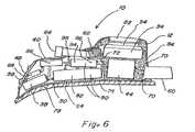
- FIG. 6illustrates a side view of an embodiment of a positive airway pressure apparatus in accordance with aspects of the present inventions with at least a portion of the housing in cross-section;
- FIG. 7illustrates a side view of another embodiment of a positive airway pressure apparatus in accordance with aspects of the present inventions with at least a portion of the housing in cross-section;
- FIG. 8is a diagram illustrating exemplary components of positive airway pressure apparatus in accordance with aspects of the present inventions.
- the present inventionsprovide positive airway pressure apparatus 10 and associated methods for use in conjunction with positive airway pressure therapies.
- the figuresgenerally illustrate embodiments of positive airway pressure apparatus 10 including aspects of the present inventions.
- the particular exemplary embodiments of the positive airway pressure apparatus 10 illustrated in the figureshave been chosen for ease of explanation and understanding of various aspects of the present inventions. These illustrated embodiments are not meant to limit the scope of coverage but instead to assist in understanding the context of the language used in this specification and the appended claims. Accordingly, variations of positive airway pressure apparatus 10 for use in positive airway pressure therapies that are different from the illustrated embodiments may be encompassed by the appended claims.
- Positive airway pressure apparatus 10in accordance with aspects of the present inventions are generally configured to be secured relative to the head of a user.
- the positive airway pressure apparatus 10are configured to position a mask 16 in communication with the airways of a user to provide pressurized air and/or other gases for positive airway pressure therapy.
- the therapymay provide constant or variable positive airway pressure to the airways of the user as will be recognized by those skilled in the art upon review of the present disclosure.
- the positive airway pressure apparatus 10 in accordance with the present inventionsinclude at least a housing 12 , a blower 14 and a mask 16 .
- the housing 12is generally configured to be secured to the head of a user. In certain aspects, the housing 12 may be configured to be secured on one or both of the crown or the forehead of a user.
- the blower 14is secured to the housing 12 .
- the blower 14is typically secured on or in the housing 12 .
- the blower 14is generally configured to generate a flow of pressurized air and/or other gas for a user's respiratory therapy.
- the flow of pressurized airis directed through an air delivery passage 28 to the mask 16 .
- the air delivery passage 28may be defined by the housing 12 and/or an air delivery tube 18 .
- the mask 16is generally configured to communicate pressurized air to the airways of a user.
- the mask 16may be particularly configured to direct air from the air delivery passage 28 into airways of a patient.
- the mask 16is secure over one or both of the mouth and the nose of a user.
- a seal or other portion of the maskis typically configured to sealingly engage an aspect of the patient's anatomy such that a positive airway pressure therapy may be administered to a user.
- the mask 16generally defines a mask passage 26 having a mask inlet 36 , and one or more mask outlets 46 .
- the one or more mask outlets 46may include one or more mask seals 56 to sealingly engage aspects of the user's anatomy.
- the mask seals 56may be removable and interchangeable to permit proper fitment and/or replacement of worn mask seals 56 .
- the mask outlet 46 and the seals 56may be formed as a unitary structure.
- the mask passage 26is defined by the mask 16 and is configured to receive pressurized air from the blower 14 through the mask inlet 36 .
- the mask inlet 36may communicate with the air delivery passage 28 to receive pressurized air from the blower 14 .
- the mask 16may be secured to the housing 12 and/or the air delivery tube 18 to permit communication of air from air delivery passage 28 into mask passage 26 .
- portions of mask 16 and/or mask inlet 36may be configured to receive an air delivery tube 18 or to be received by an air delivery tube 18 .
- the mask outlet 46is defined by the mask body and/or the seal(s) 56 of the mask 16 .
- the mask outlet 46is configured to communicate air from the passage 26 to the airway of a user.
- the seal 56 or seals 56are typically configured to abut a portion of the face of a user to permit pressurized air to be communicated through the passage 26 to the airway of a user from the mask outlet 46 .
- Portions of mask 16may be formed from a rigid or substantially rigid material while other portions are formed from a compliant material as will be recognized by those skilled in the art upon review of the present disclosure.
- Various stiffening or shaping wiresmay be integrated into the mask 16 or secured to the mask 16 .
- the wiresmay be configured to assist in the fitment of the mask 16 or otherwise as will be recognized by those skilled in the art.
- the mask 16may be configured as a face mask, a nose mask, a pair of nares seals, a mouth piece, or otherwise as will be recognized by those skilled in the art, upon review of the present disclosure.
- the mask 16is secured to the housing 12 .
- the mask 16may be secured relative to housing 12 .
- the mask 16may exert a force about a moment arm extending from the housing 12 , may be held in tension between aspects of the users face and the housing 12 , may exert a combination of such forces, or may otherwise contact a user's anatomy to permit adequate sealing for administration of a positive airway pressure therapy.
- One or more mounts 22may be secured to the mask 16 .
- the mask 16may be biased against a user's anatomy with the one or more mounts 22 .
- the mounts 22may be configured as one or more bands 32 to sealably secure the mask 16 over at least an aspect of the user's anatomy.
- the mask 16may be sealably secured over at least an aspect of the face of a user by one or more of the delivery tube 18 , a mask support 20 and the housing 12 .
- masks 16may be cantilevered against a user's face or other portions of the user's anatomy from the housing 12 .
- the mask 16may include one or more supports 20 to permit the mask 16 to exert sufficient force against the face or portion thereof of the user to seal the mask 16 against the user to permit the administration of a positive airway pressure therapy.
- the air delivery tube 18 or aspects of air delivery tube 18may function as the mask support 20 as is generally illustrated in FIGS. 1 and 3 .
- the mask 16may be secured directly to the housing 12 , may be secured to the housing 12 with a mask support 20 , or may be otherwise secured as will be recognized by those skilled in the art upon review of the present disclosure.
- the housing 12is generally configured to be stably secured to the head of a user.
- One or more mounts 22may be provided to secure the housing 12 to the user's head.
- the structure of the housing 12may be unitary or composite in structure.
- the housing 12may include a base 30 and a cover 40 .
- the base 30 and the cover 40may be integral, inter-lockable, hingably attached to one another or otherwise securable to one another.
- portions of the base 30 and the cover 40are integrally formed as two components, such as left and right halves, which may be secured to one another to form the housing 12 .
- the base 30 and the cover 40are formed as two components, such as top and bottom halves, which may be secured to one another to form the housing 12 .
- the housing 12is configured to be secured over the top of the head of a user, over aspects of the top of the head and forehead of a user, or over the forehead of a user.
- a lower housing surface 24 of the housing 12may be shaped to generally conform to the portion of the head to which the housing 12 is intended to be positioned and secured with the mount 22 . Accordingly, the lower housing surface 24 may be flat, may include one or more curves 78 or may be otherwise shaped or configured as will be recognized by those skilled in the art upon review of the present disclosure. In certain aspects, at least a portion of the lower housing surface 24 may be defined by the base 30 .
- the housing 12may include a base 30 to which the blower 14 and other components are secured and a cover 40 which is securable over the base 30 to define a housing interior 72 .
- the base 30may be formed from a rigid or a flexible material. When flexible or otherwise configured as will be recognized by those skilled in the art, the base 30 or other structure defining the lower housing surface 24 of the housing 12 may be configured to be shaped to the contours of the head of a user.
- the base 30 or other structure defining the lower housing surface 24 of the housing 12may be configured with a curve 78 or one or more flexible sections or hinges to permit the lower housing surface 24 to be more closely contoured to the shape of the head of a user.
- Other or alternative structures and materialsmay be provided to permit the housing 12 to be comfortably and securely held on the head of a user as will be recognized by those skilled in the art upon review of the present disclosure.
- the housing 12may be further configured to provide a stable structure to which the mask 16 is mounted or secured either directly or indirectly. Portions of the housing 12 may define an air delivery passage 28 to communicate pressurized air from the blower 14 to the mask passage 26 of the mask 16 . In certain aspects, a portion of the air delivery passage 28 may be formed by the housing 12 and a portion may be formed by the air delivery tube 18 . In other aspects, the entirety of air delivery passage 28 may be formed by the air delivery tube 18 or the housing 12 .
- the housing 12may include a pad 74 secured to at least a portion of the lower surface 24 of the housing 12 .
- the pad 74may conform to the shape of the lower surface 24 of the housing 12 .
- the pad 74may provide a cushion between the housing 12 and the head of a user.
- the pad 74may function as a structural member which is connected to or integral with the mount 22 to receive a force exerted by the mount 22 .
- the pad 74may function both as a structural member and a cushion.
- the pad 74may be made with a breathable material to reduce moisture from sweating.
- the pad 74may function as a frictional element which may assist in stabilizing the positive airway pressure apparatus 10 in a desired position on the head of a user.
- Those skilled in the artmay recognize additional functions for a pad 74 upon review of the present disclosure.
- the blower 14is secured to the housing 12 .
- the housing 12generally provides a stable structure to which at least a blower 14 is mounted and permits the blower 14 to be secured in a position relative to the head of a user.
- at least a portion of the blower 14is secured to and enclosed within the housing 12 .
- an inner surface of the housing 12may define a housing interior 72 , typically in the form of a cavity or chamber, in which the blower 14 is secured.
- the housing 12may be further configured to secure and/or enclose at least a portion of other components of the positive airway pressure apparatus 10 such as, for example, a battery 60 , a humidifier 90 , a control unit 38 among other components when present.
- the air delivery tube 18when present, is generally configured to communicate air from the blower 14 or the portion of the air delivery passage 28 defined by housing 12 to the mask passage 26 of the mask 16 .
- the air delivery tube 18may be in the form of a hose. Typically, the air delivery tube 18 will be formed from a flexible ribbed hose. In other aspects, the air delivery tube 18 may be rigid or semi-rigid. When rigid or semi-rigid, the air delivery tube 18 may at least in part maintain alignment and seal of the mask 16 .
- the air delivery tube 18may include various damping, flexible, rotatable, bendable and/or torquable elements to reduce the forces transmitted between the housing 12 and mask 16 as a user sleeps.
- An opening at a first end of the air delivery tube 18is generally configured to communicate with the source of pressurized air.
- An opening at the second end of the air delivery tube 18is generally configured to communicate pressurized air to the passage 26 of a mask 16 .
- One or more mounts 22may be provided to secure the housing 12 relative to the head of a user.
- the mounting(s) 22may be in the form of a flexible cap, one or more rigid or semi rigid members, one or more bands 32 or various other structures alone or in combination. Those skilled in the art will recognize a wide range of additional available structures to secure the positive airway pressure apparatus 10 to the head of a user.
- the mount(s) 22may include one or more support bands 32 to secure the housing 12 relative to the head of a user.
- the support bands 32 and the housing 12may be generally configured to secure the housing 12 in a medial position on the head of a user as illustrated.
- the support bands 32are typically in the form of elongated members that are configured to exert sufficient tension to retain the housing 12 on the head of a user and maintain the mask 16 in substantially sealed communication with the airways of a user as the user sleeps.
- the support bands 32are configured as flattened straps to comfortably distribute a force over their surface area.
- the bands 32may be formed from one or more stretchable elastic materials, substantially unstretchable material, or other materials as will be recognized by those skilled in the art upon review of the present disclosure.
- the support bands 32may be integrally formed or interconnected with one another and the housing 12 by a variety of mechanical linkages.
- the one or more of the support bands 32may have adjustable lengths to permit the proper fitting of the positive airway pressure apparatus 10 to a user.
- the support bands 32may incorporate various buckles, snaps, hook and loop type fasteners, such as that sold under the trade name Velcro®, or other components to link and/or permit relative adjustment of the support bands 32 .
- Various aspects of the support bands 32may be adjustable by a user. These aspects may include length, relative positions or other aspects as will be recognized by those skilled in the art upon review of the present disclosure.
- the support bands 32may include one or more of a circumferential band 42 , a first lateral stabilizing band 52 , a second lateral stabilizing band 52 , and a chin band 62 .
- the support bands 32are generally configured to secure the relative position of the housing 12 on the head of a user.
- One or more of the support bands 32may be secured to the housing 12 .
- the circumferential band 42may be configured to extend around at least a portion of the head of a user.
- a portion of the housing 12may be secured to the circumferential band 42 .
- the first and second lateral stabilizing bands 52generally extend between the circumferential band 42 and the housing 12 .
- the blower 14typically includes an air pressurizing assembly 34 having a blower motor 44 .
- the blower 14may be particularly configured for noise abatement and vibration reduction.
- the blowermay include an air bearing for noise abatement and vibration reduction as well as wear characteristics.
- the blower 14may be particularly configured to reduce vibration, and noise as will be recognized by those skilled in the art upon review of the present disclosure.
- the air pressurizing assembly 34typically includes a blower inlet 54 to receive air and a blower outlet 64 to direct pressurized air toward the air delivery passage 28 .
- the blower 14is generally adapted to generate and deliver pressurized air to the blower outlet 64 of the air pressurizing assembly 34 .
- the blower 14may also include one or more noise absorption baffles and/or resonators.
- a Helmholtz type resonator 68may be in fluid communication with the blower outlet 64 . As illustrated, the Helmholtz type resonator may be secured adjacent to the blower outlet 64 . In other aspects, the Helmholtz type resonator 68 may be secured to the blower inlet 54 or otherwise be positioned in communication with the pressurized air passage 28 .
- the air pressurizing assembly 34may include one or more of various fans, turbines, impellers, pumps, ducts, inlets, conduits, passages, sensors, mufflers, and other components configured to pressurize air as will be recognized by those skilled in the art upon review of the present disclosure.
- the various fans, turbines, impellers, and/or pumpsare typically driven by the blower motor 44 .
- the blower motor 44may be connected to the air pressurizing assembly 34 directly through a drive shaft or indirectly through one or more, belts, chains, gears, pulleys, shafts or other components as will be recognized by those skilled in the art.
- the components of the blower 14may be selected to reduce or eliminate noise and vibration.
- the components of the blower 14may also be selected and configured to reduce the overall mass of the positive airway pressure apparatus.
- a power source 80is typically required to power the components of the positive airway pressure apparatus 10 .
- the power source 80may be a household electrical outlet providing alternating (AC) current or may be a battery 60 .
- the power source 80may be remotely locatable or may be secured to the housing 12 .
- a direct current (DC) converter 108may be provided to appropriately convert an alternating current of an outlet to a direct current which is typically utilized by the components of the positive airway pressure apparatus 10 .
- the DC converter 108may be positioned at any convenient location on the power supply cord to permit its positioning on adjacent bedside table, under the pillow of the user, on the floor, or elsewhere as will be recognized by those skilled in the art upon review of the present disclosure.
- the power source 80may include a battery 60 .
- the battery 60may be directly connected to the DC converter 108 while the converter 108 is connected to a household electrical outlet and function as a backup power source in the event of a power outage or may be configured to be the sole source of power for the components of the positive airway pressure apparatus 10 .
- the battery 60When connected to a household electrical outlet, the battery 60 may be maintained in a fully charged condition until a power outage. If the external power source is not provided or fails, the battery 60 may power the blower 14 and other components until power from the primary external power source 80 is regained or the battery 60 has discharged.
- the battery 60is typically removable from the housing 12 for purposes of recharging or replacement.
- the battery 60may include at least one interlock 70 to removably secure the battery 60 from the housing 12 .
- the battery 60may be remotely located and electrically connected to the components of the positive airway pressure apparatus 10 by a cable. In this configuration, electrical connectors are typically provided on the cable and the positive airway pressure apparatus 10 to communicate electricity to the various components of the positive airway pressure apparatus 10 .
- a humidifier 90may be provided to communicate moisture into the pressurize air passing through the air delivery passage 28 to humidify the pressurized air delivered to the user.
- the moisture provided by the humidifier 90may be in the form of water vapor, liquid water droplets, mist, micro-droplets, fog, or various combinations of liquid water and water vapor.
- the pressurized airmay be humidified for therapy, comfort, or other reasons, as will be recognized by those skilled in the art upon review of the present disclosure.
- the humidifier 90may be secured to or within the housing 12 .
- the humidifier 90generally includes at least a humidifier reservoir 92 and, in certain configurations, a humidifier pump 94 or humidifier heater 96 .
- the humidifier 90may add moisture and/or therapeutic agents to the air delivered to the user.
- the humidifier 90includes a humidifier reservoir 92 secured within the housing 12 .
- a fill tube accessible by a usermay be provided on the housing 12 for filling the humidifier reservoir 92 without removing portions of the housing 12 or humidifier reservoir 92 .
- the humidifier reservoir 92typically contains water and/or therapeutic agents to be introduced as part of the user's therapy.
- the humidifier reservoir 92may be in fluid communication with a humidification port 98 to introduce moisture from the humidifier reservoir 92 into the pressurized air produced by the blower 14 .
- the humidifier reservoir 92may be resident on the housing 12 or may be positioned remote from the housing 12 as will be recognized by those skilled in art upon review of the present disclosure.
- the humidification port 98may be anywhere along mask passage 26 , the air delivery passage 28 , and/or within aspects of the air pressurizing assembly 34 . In some aspects, there may be a plurality of humidification ports 98 to introduce moisture at various points along the mask passage 26 , the air delivery passage 28 , and/or within aspects of the air pressurizing assembly 34 .
- the humidifier reservoir 92may include baffles, absorbent materials, or other features to inhibit the movement of water within the humidification reservoir.
- the humidifier heater 96may heat the water and/or therapeutic agents in the reservoir 92 to facilitate their introduction into the pressurized air within pressurized air passage 28 and/or for the comfort or therapy of the user. In certain aspects, the humidifier heater 96 may provide a rate of evaporation adequate to humidify the air delivered to the user.
- the humidifier pump 94 or a series of humidifier pumps 94may be provided to introduce the moisture into the pressurized air at the humidification port 98 .
- the humidifier heater 96may additionally or alternatively assist in the introduction of moisture into the pressurized air at the humidification port 98 .
- some configurationsmay utilize gravity, capillary action or other configurations or methodologies as will be recognized by those skilled in the art to additionally or alternatively assist in the introduction of moisture into the pressurized air at the humidification port 98 .
- the moisturemay be introduced as, for example, a spray or a vapor, or combinations thereof.
- nozzles, sprayers, orifices, jets, matrixes, meshes, membranes, wicking materials and similar fluid transfer devicesmay be provided at the humidification port 98 or otherwise as will be recognized by those skilled in the art to introduce the moisture into the pressurized air in the air delivery passage 28 .
- a control unit 38may be provided to control one or more components of the positive airway pressure apparatus 10 .
- the control unit 38may be particularly adapted to control a blower 14 .
- the control unit 38may include one or more circuits and/or may include one or more microprocessors as well as a computer readable memory.
- the control unit 38may be positioned within or on the housing 12 , but may be otherwise positioned or located, including remotely, as will be recognized by those skilled in the art upon review of the present disclosure.
- the control unit 38is typically configured to output one or more control signals to various components of the positive airway pressure apparatus 10 .
- the control unit 38in some aspects may be adapted to receive one or more signals from one or more components of the positive airway pressure apparatus 10 .
- the control unit 38may process or otherwise utilize the signals from the components of the positive airway pressure apparatus 10 in formulating the one or more control signals output to various components.
- control unit 38may control the blower 14 in response to information including commands from the control interface 48 .
- the control interface 48includes one or more input devices, such as buttons or a touch-screen for example, to enter inputs for controlling features of the apparatus 10 .
- the control interface 48may also include a display and/or indicator lights to convey information about the operation of the apparatus 10 to a user or a health care professional.
- the control interface 48may be in communication with the control unit 38 to transfer information to and/or from the control unit 38 .
- the control interface 48is in wired communication with the control unit 38 .
- the control interface 48may be secured, permanently or removably, to the housing 12 or may be otherwise positioned on components of the apparatus 10 .
- the control interface 48may also be configured as a remote control, either wired or wireless, as will be recognized by those skilled in the art upon review of the present disclosure.
- the control interface 48When configured as remote control, the control interface 48 typically includes a transmitter to transmit signals to a receiver associated with the control unit 38 and may include a receiver to receive signals from the control unit 38 .
- the transmissionmay be RF, infrared, or other means.
- the control interface 48may include one or more buttons, switches, touch screens, or other controls for controlling the blower 14 and associated components.
- FIGS. 1 to 5Bparticularly illustrate exemplary embodiments of positive airway pressure apparatus 10 in accordance with aspects of the present inventions.
- the illustrated embodimentsinclude at least a housing 12 , a blower 14 and a mask 16 .
- the positive airway pressure apparatus 10are configured to be secured medially on the heads of users with mounts 22 .
- the mounts 22generally are configured to extend about portions of the users' head to retain the housing 12 at a desired position on the head of a user and to permit the masks 16 to sealably engage the users' airways.
- the apparatus 10are generally configured to be positioned over the crown of user's head. As illustrated in FIG.
- the apparatusis generally configured to be positioned over the forehead of a user as well as over aspects of the crown of a user's head.
- the lower surfaces 24 of the housings 12are generally shaped to conform to the portion of the head to which the housing 12 is secured.
- the masks 16are secured to the housings 12 at a desired position relative to the housing 12 to facilitate the communication of pressurized air to the airways of a user. In the illustrated embodiments, the masks 16 are positioned below the housings 12 and may be positioned in front of the housings 12 as positioned on the head of a user.
- the illustrated embodimentsgenerally cantilever the mask 16 from the housings 12 to position the masks 16 or portions thereof about the airways of a user for exemplary purposes although those skilled in the art will recognize a wide range of configurations by which a mask 16 may be secured relative to the airways of a user.
- the mask 16is secured relative to the housing 12 by a tube 18 that is integrally formed with the housing 12 .
- the illustrated tube 18is substantially rigid to function as a support 20 for maintaining the nares seals 56 of the mask 16 sealably engaged against the nares of a user during sleep.
- One or more adjustment members 66may be provided on one or more of the housing 12 , the mask 16 , the air delivery tube 18 , or the mask support 20 .
- an adjustment member 66 in the form of a vertical adjustment member 102may be provided to adjust the positioning of mask 16 up and down and a horizontal adjustment member 100 may be provided to adjust the closeness of the mask 16 or other structure to the face of a user.
- the housing 12is configured with a base 30 and a cover 40 .
- the housing 12encloses a blower 14 , not shown, within a housing interior 72 . More particularly, the blower 14 is secured within the housing interior 72 defined between the cover 40 and the base 30 .
- the base 30defines a lower surface 24 configured with a downward curve 78 toward the front portion to conform to the shape of head between the forehead and crown.
- a mount 22 in the form of support bands 32is secured to the base 30 .
- the support bands 32 of the mount 22include a circumferential band 42 and a first and a second stabilizing band 52 .
- the circumferential band 42is generally configured to extend about at least a portion of the circumference of a user's head.
- the housing 12is secured to the circumferential band 42 at a location toward the anterior portion of the housing 12 .
- An adjustable attachmentmay be provided on a posterior portion of the circumferential band 42 .
- the first and second lateral stabilizing bands 52are generally configured to stabilize the posterior portion of the base 30 of the housing 12 on the head of a user.
- the first and second lateral stabilizing bands 52may each define at least a first end and a second end.
- the first and second lateral stabilizing bands 52may be integral with or may be adjustably secured to the circumferential band 42 at their first ends.
- the second ends of each of the first and second lateral stabilizing bands 52may be secured to a posterior portion of the base 30 of the housing 12 .
- the cover 40defines a housing air inlet 82 to communicate air into the housing interior 72 .
- the housing air inlet 82may be positioned on an upper surface of the housing 12 as shown or on other surfaces as one as will be recognized by those skilled in the art upon review of the present disclosure.
- the housing air inlet 82may communicate air directly into a blower inlet 54 of the blower 14 within the housing 12 .
- a control interface 48is also positioned on an upper surface of the housing 12 . As illustrated, the control interface 48 may include one or more controls 58 .
- the controls 58may be shaped, textured or otherwise configured to permit a user to differentiate between the controls 58 by touch.
- thismay include orientation of the controls 58 , relative to one another and/or the housing, or sequence of the controls 58 as in a menu sequence when a touch screen is utilized.
- the blower 14is secured within the housing 12 with the blower inlet 54 in fluid communication with the housing inlet 82 and the blower outlet 64 in fluid communication with the pressurized air passage 28 defined by the housing 12 .
- the combination tube 18 /mask support 20extends forward and, then, downward from the housing 12 from which the first end of the combination tube 18 /mask support 20 to position the second end of the combination tube 18 /mask support 20 near or over the nose of a user when worn by the user.
- the mask passage 26 defined by mask 16is in fluid communication with pressurized air passage 28 at the second end of the combination tube 18 /mask support 20 .
- the pressurized air passage 28is in fluid communication with the mask passage 26 at the mask inlet 36 .
- a first and a second mask seal 56 configured to permit the passage of pressurized air,define each of a first and second mask outlet 46 , respectively, to sealably engage a nares of a user.
- the mask 16is secured relative to the housing 12 by a tube 18 that is adjustably secured to the housing 12 .
- the tube 18also functions as a support 20 for the mask 16 .
- the illustrated tube 18is substantially rigid to function as a support 20 for maintaining the nares seals 56 of the mask 16 sealably engaged against the nares of a user during sleep.
- a generally tensile forcemay be applied between the mask 16 and the housing 12 to sealably engage the mask 16 within the nares of a user.
- the tube 18 as illustratedis vertically adjustable by a rotatable fitting 50 rotatably secured to the housing 12 and threadedly engaged with the tube 18 and permit adjustment along a substantially vertical axis.
- An adjustment member 66allows adjustment of the position of the tube 18 and/or mask 16 to be made closer or further from the face as well as the angle relative to the plane of the face in order to accommodate differing anatomy.
- the housing 12encloses a blower 14 , not shown, within a housing interior 72 .
- a battery 60is also secured to the housing 12 .
- the housing 12defines a lower surface 24 configured with an approximately ninety (90) degree curve 78 to conform to the shape of the head between the forehead and crown.
- a pad 74is secured to the lower surface 24 of the housing 12 to provide, in some embodiments, a more comfortable contact with a user's head.
- a mount 22 in the form of support bands 32is secured through fittings 76 in the form of eyelets to the pad 74 .
- the support bands 32 of the mount 22include a circumferential band 42 and a first and a second stabilizing band 52 .
- the circumferential band 42is generally configured to extend about at least a portion of the circumference of a user's head.
- the pad 74is secured to the circumferential band 42 at a location toward the anterior portion of the pad 74 .
- Each of the ends of the support bands 32may be provided with hook and loop type fasteners, for example, on opposing sides of the support bands 32 to among other thing permit the adjustability of length and/or tension when the support bands 32 are secured through fittings 76 .
- the first and second lateral stabilizing bands 52are generally configured to stabilize the posterior portion of the pad 74 on the head of a user.
- the first and second lateral stabilizing bands 52may each define at least a first end and a second end.
- the first and second lateral stabilizing bands 52may be integral with or may be adjustably secured to the circumferential band 42 at their first ends.
- the second ends of each of the first and second lateral stabilizing bands 52may be secured to a posterior portion of the pad 74 .
- the housing 12defines a housing air inlet 82 to communicate air into the housing interior 72 .
- the housing air inlet 82is positioned on a substantially dorsal surface of the housing 12 .
- the housing air inlet 72may communicate air directly into a blower inlet 54 of the blower 14 secured within the housing 12 .
- a control interface 48is also positioned on a lateral surface of the housing 12 .
- control interface 48may include one or more controls 58 .
- the controls 58may be shaped, textured or otherwise configured to permit a user to differentiate between the controls 58 by touch, orientation, or sequence as in a menu sequence with a touch screen approach.
- the blower 14is secured within the housing 12 with the blower inlet 54 in fluid communication with the housing inlet 82 and the blower outlet 64 in fluid communication with the pressurized air passage 28 defined by the housing 12 .
- the combination tube 18 /mask support 20extends downward from the housing 12 from which the first end of the combination tube 18 /mask support 20 is adjustably secured to position the second end of the combination tube 18 /mask support 20 and mask 16 at a desired location relative to the nose of a user.
- the mask passage 26 defined by mask 16is in fluid communication with pressurized air passage 28 at the second end of the combination tube 18 /mask support 20 .
- the pressurized air passage 28is in fluid communication with the mask passage 26 at the mask inlet 36 .
- a first and a second mask seal 56 configured to permit the passage of pressurized airdefine each of a first and second mask outlet 46 , respectively, to sealably engage a nares of a user.
- the mask 16is secured relative to the housing 12 by an air delivery tube 18 that is integrally formed with the housing 12 .
- the tube 18is supported by substantially rigid mask supports 20 to maintain the mask 16 sealably engaged around the nose of a user during sleep.
- One or more adjustment members 66may be provided on one or more of the housing 12 , the mask 16 , the air delivery tube 18 , or the mask support 20 .
- an adjustment member 66 in the form of a vertical adjustment member 102may be provided to adjust the positioning of mask 16 up and down and a horizontal adjustment member 100 may be provided to adjust the closeness of the mask 16 or other structure to the face of a user.
- the tube 18is supported by substantially rigid mask supports 20 to maintain the nares seals 56 of the mask 16 sealably engaged against the nares of a user during sleep.
- the housing 12encloses a blower 14 , not shown, within a housing interior 72 defined by the housing 12 .
- the housing 12defines a lower surface 24 configured with a downward curve 78 toward the front portion to substantially conform to the shape of the head between the forehead and crown.
- a pad 74is secured to the lower surface 24 .
- a mount 22 in the form of support bands 32is secured to the housing 12 .
- the support bands 32 of the mount 22include a circumferential band 42 and a first and a second stabilizing band 52 .
- the circumferential band 42is generally configured to extend about at least a portion of the circumference of a user's head.
- the housing 12is secured to the circumferential band 42 at a location toward the anterior portion of the housing 12 .
- An adjustable attachmentmay be provided on a posterior portion of the circumferential band 42 .
- the first and second lateral stabilizing bands 52are generally configured to stabilize the posterior portion of the housing 12 on the head of a user.
- the first and second lateral stabilizing bands 52may each define at least a first end and a second end.
- the first and second lateral stabilizing bands 52may be integral with or may be adjustably secured to the circumferential band 42 at their first ends.
- the second ends of each of the first and second lateral stabilizing bands 52may be secured to a posterior portion of the housing 12 .
- the housing 12defines a housing air inlet 82 to communicate air into the housing interior 72 .
- the housing air inlet 82is positioned on an upper surface of the housing 12 .
- the housing air inlet 82may communicate air directly into a blower inlet 54 of the blower 14 within the housing 12 .
- the blower 14is secured within the housing 12 with the blower inlet 54 in fluid communication with the housing inlet 82 and the blower outlet 64 in fluid communication with the pressurized air passage 28 defined by the housing 12 .
- the tube 18 and the mask support 20extend forward and, then, downward from the housing 12 to which the first end of the tube 18 and the mask support 20 are secured.
- the mask support 20is generally configured to position the mask 16 near or over the nose of a user when worn by the user.
- the mask passage 26 defined by mask 16is in fluid communication with pressurized air passage 28 defined through the tube 18 at the second end of the tube 18 .
- the pressurized air passage 28is in fluid communication with the mask passage 26 at the mask inlet 36 .
- a first and a second mask seal 56 configured to permit the passage of pressurized airdefine each of a first and second mask outlet 46 , respectively, to sealably engage the face of a user about the nose as illustrated in FIG. 3 and within the nares of a user as illustrated in FIGS. 4A to 5B .
- control interface 48is provided as a remote control.
- the control interface 48may include one or more controls 58 .
- the embodiment of FIG. 5Ais shown with a remotely positionable DC converter 108 including a power cord extending to a power source 80 such as a household wall outlet.
- the embodiment of FIG. 5Bis shown with a remotely positionable battery 60 .
- the housing 12may be configured to enclose and/or secure multiple components of the positive airway pressure apparatus 10 within a housing interior 72 .
- the housing 12may include a base 30 and a cover 40 which define the housing interior 72 as the open space between the base 30 and cover 40 when secured to one another.
- the lower surface 24 of base 30may define a curve 78 to conform to aspects of the head of a user.
- a pad 74may be secured directly to the lower surface 24 of the base 30 .
- the pad 74may conform to the curve 78 on the lower surface 24 of the base 30 .
- the blower 14 , the mask 16 , the air delivery tube 18 (not shown), the mask support 20 (not shown), the humidifier 90 and other components of positive airway pressure apparatus 10may be secured directly or indirectly to the housing 12 of positive airway pressure apparatus 10 .
- the componentsare secured directly or indirectly to the base 30 or the cover 40 of the housing 12 .
- the componentsare also in communication with one another as will be recognized by those skilled in the art upon review of the present disclosure.
- the communicationmay be to transfer power, electrical or mechanical.
- the communicationmay be to communicate data.
- the communicationmay be to communicate mechanical forces.
- a battery 60is removably secured within the rear portion of the housing 12 with at least a portion of the battery 60 extending into housing interior 72 .
- the battery 60is in electrical communication either directly or indirectly with each of the components which require electrical power for operation.
- the blower 14may be secured within a rear portion of a base 30 of the housing 12 as well as to the cover of the housing 40 .
- the blower motor 44is secured to the base 30 and the air pressurizing assembly 34 is secured to the cover 40 for exemplary purposes.
- the blower motor 44is connected to the air pressurizing assembly 34 to permit the blower motor 44 to confer power to the air pressurizing assembly 34 .
- the blower motor 44is in electrical communication with the battery 60 .
- a sound deadening material 84may be provided within at least a portion of the housing interior 72 . In certain aspects, the sound deadening material 84 may be positioned about at least a portion of the blower 14 .
- the sound deadening material 84may be injection-molded foam.
- the control unit 38is positioned in an anterior portion of the housing interior 72 and is secured to the base 30 .
- the control unit 38is in communication with blower motor 44 to provide control signals to the blower motor 44 .
- the control unit 38is in electrical communication with the battery 60 .
- the control interface 48is secured to an anterior portion of the cover 40 for exemplary purposes.
- the controls 58 of the control interface 48are generally positioned and configured to permit a user to access the controls 58 .
- the control interface 48is in communication with the control unit 38 to at least provide control signals to the control unit 38 .
- the control interface 48is also in electrical communication with the battery 60 .
- the control unit 38is in communication with humidification pump 94 and/or humidification humidifier heater 96 to provide control signals to the humidification pump 94 and/or humidification humidifier heater 96 .
- the humidification pump 94 and/or humidification humidifier heater 96is in electrical communication with the battery 60 .
- a noise cancellation speaker 86 and, in some aspects, a microphone 88may be provided for purposes of noise cancellation.
- An outputmay be produced by the control unit 38 to generate a mitigating or cancelling waveform from the noise cancellation speaker 86 to reduce or eliminate the noise perceived by the user from the operation of the blower 14 and/or humidifier 90 .
- the microphone 88may produce a signal indicative of the noise produced by the blower 14 and/or humidifier 90 .
- the signalmay be processed by the control unit 38 and an output produced by the control unit 38 to generate a mitigating or cancelling waveform from the noise cancellation speaker 86 to reduce or eliminate the noise perceived by the user from the operation of the blower 14 and/or humidifier 90 .
- the housing 12 of the respiratory therapy apparatus 10may have a modular configuration.
- the modular configurationincludes the base 30 in the form of a head mounted platform module 110 to which the mask support 20 and the mount 22 are secured.
- One or more modulesmay be secured to the head mounted platform module 110 .
- a humidification module 112 and a blower module 114are secured to the head mounted platform module 110 .
- the humidifier module 112may be independent from blower module 114 , as shown, or contained in a common module (not shown).
- Humidifier module 112 and blower module 114may be connected together by one or more of screws, bolts, snaps, slots, or not physically attached together, but for the blower outlet 64 being in communication with the humidifier inlet 104 through pressurized the air passage 28 .
- the lower surface 24 of the head mounted platform module 110may define a curve 78 to conform to aspects of the head of a user.
- a pad 74may be secured directly to the lower surface 24 of the head mounted platform module 110 .
- the pad 74may conform to the curve 78 on the lower surface 24 of the head mounted platform module 110 .
- the humidification module 112defines a housing interior 72 in which the humidifier 90 and other components may be secured.
- the blower module 114defines a housing interior 72 in which for the blower 14 , the control unit 38 , and the battery 60 are secured for exemplary purposes and in which other components may be secured.
- the humidification module 112 and the blower module 114may be removably attached to the head mount platform module 110 .
- the humidification module 112 and/or the blower module 114may be attached to the head mount platform module 110 , one another or to other components with one or more attachments 120 .
- the attachments 120may be in the form of screws, bolts, snaps, slots, sleeves, hook and loop type fasteners, various fittings and couplers or other engagement mechanisms as will be recognized by those skilled in the art upon review of the present disclosure.
- the attachments 120may further include dampers or may function as dampers to mitigate or prevent the transmission of vibration between modules.
- the air delivery tube 18is secured in fluid communication with the humidifier outlet 106 and the blower outlet 64 is in fluid communication with the humidifier inlet 104 to form a pressurized air passage 28 extending between the blower 14 and the mask 16 .
- the various componentsmay in various fittings and/or couplers to permit the sealed engagement of abutting portions of modules 112 , 114 , air delivery tube 18 , or other tubing or components of the positive airway pressure apparatus that may be associated with defining the pressurized air passage 28 .
- a battery 60may reside within blower module 114 as illustrated, may be associated with other modules, may be provided in an independent battery module, or may be provided remotely as will be recognized by those skilled in the art upon review of the present disclosure.
- a sound deadening material 84may be provided within at least a portion of the housing interior 72 of at least one of the blower module 114 and the humidifier module 112 .
- the sound deadening material 84may be injection-molded foam. In certain aspects, the sound deadening material 84 may be positioned about at least a portion of the blower 14 .
- blower 14may be secured to housing 12 in accordance with aspects of the present inventions.
- control unit 38may be secured to housing 12 .
- control interface 48battery 60 , humidifier 90 , and various sensors or components thereof may be remote from housing 12 .
- additional componentsmay be included with positive airway pressure apparatus 10 that may be secured to or remote from the housing 12 upon review of the present disclosure which are in accordance with aspects of the present inventions.
- a usermay secure the housing 12 , the blower 14 and the mask 16 to his or her head.
- the mask 16is positioned in communication with the airways of the user.
- the positive airway pressure apparatus 10may be configured to administer one or more positive airway pressure therapies, including: continuous positive airway pressure therapy (CPAP), bilevel positive airway pressure therapy (BPAP), automatic positive airway pressure therapy (autoPAP), proportional positive airway pressure therapy (PPAP), non-invasive ventilation and/or other positive airway pressure therapies as will be recognized by those skilled in the art upon review of this disclosure.
- the mask 16may be sealingly secured over one or more aspects of the user's face.
- the sealis typically sufficient to prevent substantial leaking of pressurized air from the interface of the mask 16 and the user's anatomy such that effective positive airway pressure therapy can be administered to the user.
- the userthen initiates the positive airway pressure therapy.
- the pressuremay be initiated by hitting a start button secured to the housing 12 or on a remote control or otherwise as will be recognized by those skilled in the art upon review of the present disclosure.
- the pressure in the user's airwaysis then increased to a therapeutically efficacious level. Typically, this is between 4 and 20 cm of water.
- the pressuremay increase to therapeutic levels immediately upon hitting the start button.
- the pressuremay increase from an initially low or non-therapeutic level to therapeutic levels after a delay.
- the pressuremay be increased gradually or may be immediately increased from atmospheric or slightly higher pressure to a therapeutic pressure.
- the pressuremay be modulated within or between breath cycles and/or in accordance with the sleep cycle of a user as will be recognized by those skilled in the art upon review of the present disclosure. This modulation may be in response to input from sensors into the control unit of the positive airway pressure apparatus 10 .
Landscapes
- Health & Medical Sciences (AREA)
- Heart & Thoracic Surgery (AREA)
- Life Sciences & Earth Sciences (AREA)
- Engineering & Computer Science (AREA)
- Anesthesiology (AREA)
- Biomedical Technology (AREA)
- Emergency Medicine (AREA)
- Hematology (AREA)
- Pulmonology (AREA)
- Animal Behavior & Ethology (AREA)
- General Health & Medical Sciences (AREA)
- Public Health (AREA)
- Veterinary Medicine (AREA)
- Respiratory Apparatuses And Protective Means (AREA)
- Orthopedics, Nursing, And Contraception (AREA)
Abstract
Description
Claims (15)
Priority Applications (1)
| Application Number | Priority Date | Filing Date | Title |
|---|---|---|---|
| US14/100,305US9694153B2 (en) | 2006-04-10 | 2013-12-09 | Apparatus and methods for administration of positive airway pressure therapies |
Applications Claiming Priority (5)
| Application Number | Priority Date | Filing Date | Title |
|---|---|---|---|
| US79067106P | 2006-04-10 | 2006-04-10 | |
| PCT/US2007/009082WO2007117716A2 (en) | 2006-04-10 | 2007-04-10 | Apparatus and methods for administration of positive airway pressure therapies |
| US11/786,403US8020557B2 (en) | 2006-04-10 | 2007-04-10 | Apparatus and methods for administration of positive airway pressure therapies |
| US13/211,053US8631791B2 (en) | 2006-04-10 | 2011-08-16 | Apparatus and methods for administration of positive airway pressure therapies |
| US14/100,305US9694153B2 (en) | 2006-04-10 | 2013-12-09 | Apparatus and methods for administration of positive airway pressure therapies |
Related Parent Applications (1)
| Application Number | Title | Priority Date | Filing Date |
|---|---|---|---|
| US13/211,053ContinuationUS8631791B2 (en) | 2006-04-10 | 2011-08-16 | Apparatus and methods for administration of positive airway pressure therapies |
Publications (2)
| Publication Number | Publication Date |
|---|---|
| US20140166007A1 US20140166007A1 (en) | 2014-06-19 |
| US9694153B2true US9694153B2 (en) | 2017-07-04 |
Family
ID=87264195
Family Applications (3)
| Application Number | Title | Priority Date | Filing Date |
|---|---|---|---|
| US11/786,403Active2030-07-15US8020557B2 (en) | 2006-04-10 | 2007-04-10 | Apparatus and methods for administration of positive airway pressure therapies |
| US13/211,053Active2027-09-08US8631791B2 (en) | 2006-04-10 | 2011-08-16 | Apparatus and methods for administration of positive airway pressure therapies |
| US14/100,305ActiveUS9694153B2 (en) | 2006-04-10 | 2013-12-09 | Apparatus and methods for administration of positive airway pressure therapies |
Family Applications Before (2)
| Application Number | Title | Priority Date | Filing Date |
|---|---|---|---|
| US11/786,403Active2030-07-15US8020557B2 (en) | 2006-04-10 | 2007-04-10 | Apparatus and methods for administration of positive airway pressure therapies |
| US13/211,053Active2027-09-08US8631791B2 (en) | 2006-04-10 | 2011-08-16 | Apparatus and methods for administration of positive airway pressure therapies |
Country Status (6)
| Country | Link |
|---|---|
| US (3) | US8020557B2 (en) |
| EP (1) | EP2012858A2 (en) |
| JP (1) | JP5295949B2 (en) |
| CN (1) | CN101466429A (en) |
| BR (1) | BRPI0709500A2 (en) |
| WO (1) | WO2007117716A2 (en) |
Families Citing this family (86)
| Publication number | Priority date | Publication date | Assignee | Title |
|---|---|---|---|---|
| NZ524990A (en) | 2000-09-28 | 2005-02-25 | Invacare Corp | Carbon dioxide-based BI-level CPAP control |
| US7089941B2 (en)* | 2002-08-20 | 2006-08-15 | Bordewick Steven S | Face mask support |
| US7845353B2 (en)* | 2002-08-20 | 2010-12-07 | Aeiomed, Inc. | Face mask support |
| EP1675639A4 (en) | 2003-09-25 | 2009-12-02 | Resmed Ltd | Ventilator mask and system |
| BRPI0709500A2 (en) | 2006-04-10 | 2011-07-26 | Aeiomed Inc | apparatus for providing positive airway pressure for the treatment of sleep apnea, chronic pulmonary obstruction and snoring, and method for providing positive air pressure for the treatment of sleep apnea, chronic pulmonary obstruction and snoring |
| BRPI0709503A2 (en)* | 2006-04-10 | 2011-07-19 | Aeiomed Inc | device for providing positive airway pressure for the treatment of sleep apnea, chronic pulmonary obstruction and snoring |
| US20070251527A1 (en)* | 2006-04-21 | 2007-11-01 | Tiara Medical Systems, Inc. | Self-contained respiratory therapy apparatus for enhanced patient compliance and therapeutic efficacy |
| WO2007149446A2 (en)* | 2006-06-16 | 2007-12-27 | Aeiomed, Inc. | Modular positive airway pressure therapy apparatus and methods |
| WO2008028247A1 (en) | 2006-09-07 | 2008-03-13 | Resmed Ltd | Mask and flow generator system |
| SE531743C2 (en)* | 2006-12-12 | 2009-07-28 | Interspiro Ab | Breath controlled motor driven air purifying breathing apparatus |
| US20080178879A1 (en)* | 2007-01-29 | 2008-07-31 | Braebon Medical Corporation | Impeller for a wearable positive airway pressure device |
| EP2144674A4 (en)* | 2007-04-13 | 2012-12-26 | Invacare Corp | Apparatus and method for providing positive airway pressure |
| US20090078255A1 (en)* | 2007-09-21 | 2009-03-26 | Bowman Bruce R | Methods for pressure regulation in positive pressure respiratory therapy |
| US20090078258A1 (en)* | 2007-09-21 | 2009-03-26 | Bowman Bruce R | Pressure regulation methods for positive pressure respiratory therapy |
| NZ602818A (en)* | 2008-01-31 | 2014-01-31 | Resmed Ltd | Respiratory apparatus |
| US8752546B2 (en)* | 2008-04-23 | 2014-06-17 | General Electric Company | System and method for mobilizing occlusions from a breathing tube |
| DE102008022663B4 (en) | 2008-05-07 | 2012-10-31 | Schauenburg Hose Technology Gmbh | Stretch hose |
| US9505164B2 (en) | 2009-12-30 | 2016-11-29 | Schauenburg Technology Se | Tapered helically reinforced hose and its manufacture |
| US20100163043A1 (en)* | 2008-06-25 | 2010-07-01 | Hart William T | Self-contained oral ventilation device |
| EP2181726B1 (en)* | 2008-10-31 | 2017-04-19 | ResMed Ltd. | Systems for guiding transitions between therapy modes in connection with treatment and/or diagnosis of sleep-disordered breathing |
| WO2010080709A1 (en) | 2009-01-08 | 2010-07-15 | Hancock Medical | Self-contained, intermittent positive airway pressure systems and methods for treating sleep apnea, snoring, and other respiratory disorders |
| US9964238B2 (en) | 2009-01-15 | 2018-05-08 | Globalmed, Inc. | Stretch hose and hose production method |
| US10238822B2 (en) | 2009-05-29 | 2019-03-26 | Resmed Limited | PAP system |
| EP2464404B1 (en) | 2009-08-11 | 2017-06-28 | ResMed Motor Technologies Inc. | Single stage, axial symmetric blower and ventilator |
| NZ613721A (en)* | 2009-08-28 | 2015-02-27 | Resmed Ltd | Pap system |
| WO2011050059A1 (en)* | 2009-10-20 | 2011-04-28 | Michael Gerard Lalonde | Integrated positive airway pressure apparatus |
| EP2317150B1 (en)* | 2009-10-29 | 2019-12-18 | ResMed Pty Ltd | Patient ventilation device and components thereof |
| CN104314843B (en) | 2009-11-19 | 2018-07-24 | 瑞思迈发动机及马达技术股份有限公司 | Air blower |
| US20110132369A1 (en)* | 2009-12-04 | 2011-06-09 | Nellcor Puritan Bennett Llc | Ventilation System With System Status Display |
| JP2013521847A (en) | 2010-03-12 | 2013-06-13 | コーニンクレッカ フィリップス エレクトロニクス エヌ ヴィ | Patient interface device with dynamic mask adjuster |
| US8539949B2 (en) | 2010-04-27 | 2013-09-24 | Covidien Lp | Ventilation system with a two-point perspective view |
| US8511306B2 (en) | 2010-04-27 | 2013-08-20 | Covidien Lp | Ventilation system with system status display for maintenance and service information |
| US8453643B2 (en) | 2010-04-27 | 2013-06-04 | Covidien Lp | Ventilation system with system status display for configuration and program information |
| SE534951C2 (en)* | 2010-06-18 | 2012-02-28 | Facecover Sweden Ab | Motor-driven Air Purifying Respirator (PAPR) |
| US9616190B2 (en) | 2010-08-27 | 2017-04-11 | Resmed Limited | PAP system |
| DE102010040771A1 (en)* | 2010-09-14 | 2012-03-15 | Medin Medical Innovations Gmbh | Respiratory mask, respiratory mask arrangement, ventilation system and packaging unit |
| WO2012094230A2 (en)* | 2011-01-03 | 2012-07-12 | Somnetics Global Pte. Ltd. | Positive airway pressure therapy apparatus and methods |
| US8327846B2 (en) | 2011-02-08 | 2012-12-11 | Hancock Medical, Inc. | Positive airway pressure system with head position control |
| WO2012113027A1 (en) | 2011-02-25 | 2012-08-30 | Resmed Motor Technologies Inc. | Blower and pap system |
| US9084859B2 (en) | 2011-03-14 | 2015-07-21 | Sleepnea Llc | Energy-harvesting respiratory method and device |
| US9669178B2 (en)* | 2011-05-17 | 2017-06-06 | Koninklijke Philips N.V. | Flexible member adjustable forehead support |
| EP4169558A1 (en) | 2011-06-21 | 2023-04-26 | ResMed Pty Ltd | Pap system |
| US10137264B2 (en) | 2011-07-13 | 2018-11-27 | Fisher & Paykel Healthcare Limited | Respiratory assistance apparatus |
| WO2014007655A2 (en)* | 2012-02-02 | 2014-01-09 | Fisher & Paykel Healthcare Limited | Respiratory assistance apparatus |
| EP4169560B1 (en) | 2011-07-13 | 2025-09-17 | Fisher & Paykel Healthcare Limited | Bearing mount for a compressor or blower for providing respiratory assistance |
| JP2013150684A (en)* | 2012-01-25 | 2013-08-08 | Nidec Copal Electronics Corp | Cpap device |
| US20140014110A1 (en)* | 2012-07-16 | 2014-01-16 | Phillip M. Adams | Remotely controlled positive airway-pressure apparatus and method |
| JP2014050519A (en)* | 2012-09-06 | 2014-03-20 | Nidec Copal Electronics Corp | Cpap device |
| NO334283B1 (en)* | 2012-09-21 | 2014-01-27 | Tranberg Venture Pty Ltd | Portable device for continuous, positive airway pressure |
| CN102872511B (en)* | 2012-10-03 | 2014-12-10 | 王秋华 | Miniature nostril air feeder |
| GB2507104A (en)* | 2012-10-19 | 2014-04-23 | Nicoventures Holdings Ltd | Electronic inhalation device |
| JP2015033522A (en)* | 2013-08-09 | 2015-02-19 | 日本電産コパル電子株式会社 | Cpap apparatus, and blower unit for cpap apparatus |
| CN205515844U (en) | 2012-12-18 | 2016-08-31 | 费雪派克医疗保健有限公司 | Breathe auxiliary device and be used for assembly of motor |
| US10105504B2 (en) | 2012-12-18 | 2018-10-23 | Koninklijke Philips N.V. | EAP-driven air pump for patient interfaces |
| WO2014117179A1 (en) | 2013-01-28 | 2014-07-31 | Hancock Medical, Inc. | Position control devices and methods for use with positive airway pressure systems |
| WO2014205513A1 (en) | 2013-06-25 | 2014-12-31 | Resmed Limited | Outlet connection assembly and method of making the same |
| US10549060B2 (en) | 2013-06-25 | 2020-02-04 | ResMed Pty Ltd | Outlet connection assembly and method of making the same |
| US20150165146A1 (en) | 2013-12-17 | 2015-06-18 | Bruce Bowman | Humidification system and positive airway pressure apparatus incorporating same |
| EP4166176B1 (en) | 2013-12-17 | 2025-08-06 | ResMed Pty Ltd | Apparatus for use in treating a respiratory disorder |
| US10344753B2 (en)* | 2014-02-28 | 2019-07-09 | Encite Llc | Micro pump systems |
| US20150306324A1 (en)* | 2014-04-29 | 2015-10-29 | Arturo Alejo Ayon | Self-contained continuous positive airway pressure mask and method of use |
| WO2016028525A1 (en) | 2014-08-18 | 2016-02-25 | Hancock Medical, Inc. | Portable pap device with humidification |
| AU2015365354A1 (en)* | 2014-12-19 | 2017-08-03 | Medaxor Pty Ltd | Multi-use injection system |
| USD776802S1 (en) | 2015-03-06 | 2017-01-17 | Hancock Medical, Inc. | Positive airway pressure system console |
| USD775345S1 (en) | 2015-04-10 | 2016-12-27 | Covidien Lp | Ventilator console |
| NZ773777A (en) | 2015-07-07 | 2023-12-22 | ResMed Pty Ltd | Respiratory pressure therapy device |
| FR3038748B1 (en)* | 2015-07-10 | 2019-06-07 | Physio-Assist | TOUCH USER INTERFACE FOR A TRACHEO-BRONCHIC AIR STIMULATION DEVICE |
| CN107923411B (en) | 2015-08-18 | 2021-04-23 | 株式会社村田制作所 | Air supply device |
| GB201517089D0 (en) | 2015-09-28 | 2015-11-11 | Nicoventures Holdings Ltd | Vaping heat map system and method for electronic vapour provision systems |
| EP3457926A4 (en) | 2016-05-19 | 2020-09-09 | Hancock Medical, Inc. | SYSTEM FOR DETECTING POSITIONAL OBSTRUCTIVE SLEEP APNEA |
| EP4484810A3 (en) | 2016-07-25 | 2025-03-19 | ResMed Pty Ltd | Respiratory pressure therapy system |
| US11400247B2 (en) | 2016-12-22 | 2022-08-02 | Fisher & Paykel Healthcare Limited | Breathing assistance apparatus |
| US11052214B2 (en) | 2017-01-30 | 2021-07-06 | Globalmed, Inc. | Heated respiratory hose wiring |
| CN114288512B (en) | 2017-04-23 | 2024-12-13 | 费雪派克医疗保健有限公司 | Respiratory assistance equipment |
| WO2020128829A1 (en) | 2018-12-18 | 2020-06-25 | ResMed Pty Ltd | Humidifier reservoir |
| AU2020271997B2 (en) | 2019-04-12 | 2025-05-15 | ResMed Pty Ltd | Respiratory pressure therapy system |
| WO2021084501A1 (en)* | 2019-10-31 | 2021-05-06 | ResMed Pty Ltd | Systems and methods for active noise cancellation |
| DE102019134830A1 (en)* | 2019-12-17 | 2021-06-17 | Hamilton Medical Ag | Portable ventilator powered by mains and power storage |
| CN111298315B (en)* | 2020-03-26 | 2024-10-22 | 财鼎科技(重庆)有限公司 | A multifunctional protective cap |
| USD1060658S1 (en) | 2020-12-28 | 2025-02-04 | ResMed Asia Pte. Ltd. | Patient interface |
| US11529485B1 (en) | 2021-06-15 | 2022-12-20 | Sleepnet Corporation | Positive airway pressure (PAP) mask |
| USD1043987S1 (en) | 2021-09-16 | 2024-09-24 | Somnetics International, Inc. | Housing for a positive airway pressure apparatus |
| CN117771571A (en)* | 2022-09-20 | 2024-03-29 | 霍尼韦尔国际公司 | Slidingly mounted respirator cartridge and respirator |
| US11826510B1 (en)* | 2023-05-11 | 2023-11-28 | Telesair, Inc. | HFNC system |
| US12337108B1 (en) | 2024-07-25 | 2025-06-24 | Wallenberg Union Llc | Noise-reducing air passage device and its components for use in ventilator systems |
| US12403279B1 (en)* | 2024-07-25 | 2025-09-02 | Wallenberg Union Llc | Noise-reducing respiratory device |
Citations (122)
| Publication number | Priority date | Publication date | Assignee | Title |
|---|---|---|---|---|
| BE439032A (en) | 1939-08-07 | 1940-09-30 | Auergesellschaft Ag | Device for oxygen treatment |
| US3649964A (en) | 1970-06-04 | 1972-03-21 | Willy A E Schoelz | Ventilated welders face mask |
| US3721233A (en) | 1970-10-30 | 1973-03-20 | W Montgomery | T-shaped tracheal stent |
| US3822698A (en) | 1973-01-22 | 1974-07-09 | R Guy | Powered air-purifying respirator helmet |
| US3828773A (en) | 1972-09-22 | 1974-08-13 | Theratron Corp | Nebulizing apparatus and system |
| US4381267A (en) | 1978-07-12 | 1983-04-26 | Jackson Richard R | Airway humidifier for the respiratory tract |
| US4430995A (en) | 1981-05-29 | 1984-02-14 | Hilton Joseph R | Power assisted air-purifying respirators |
| US4493614A (en) | 1982-10-08 | 1985-01-15 | Lifecare Services, Inc. | Pump for a portable ventilator |
| US4590951A (en) | 1983-06-07 | 1986-05-27 | Racal Safety Limited | Breathing apparatus |
| US4644947A (en) | 1982-04-15 | 1987-02-24 | Whitwam James G | Respirator |
| US4782832A (en) | 1987-07-30 | 1988-11-08 | Puritan-Bennett Corporation | Nasal puff with adjustable sealing means |
| US4944310A (en) | 1981-04-24 | 1990-07-31 | Somed Pty. Ltd. | Device for treating snoring sickness |
| US4957107A (en) | 1988-05-10 | 1990-09-18 | Sipin Anatole J | Gas delivery means |
| US5054480A (en) | 1990-06-14 | 1991-10-08 | Bio Medical Devices, Inc. | Personal air filtration and control system |
| US5054484A (en) | 1990-11-21 | 1991-10-08 | Hebeler Jr Robert F | Tracheostomy device |
| WO1991019527A1 (en) | 1990-06-18 | 1991-12-26 | Ponnet, Gilman En Anthony | A device for compensating for the moisture and heat losses from an artificial nose |
| US5104430A (en) | 1991-06-11 | 1992-04-14 | Her Mou Lin | Mask with an air filtering device |
| US5237987A (en) | 1990-06-07 | 1993-08-24 | Infrasonics, Inc. | Human lung ventilator system |
| EP0558147A1 (en) | 1992-02-26 | 1993-09-01 | D.J.S. & T. LIMITED PARTNERSHIP | Face mask assembly and method |
| US5349946A (en) | 1992-10-07 | 1994-09-27 | Mccomb R Carter | Microprocessor controlled flow regulated molecular humidifier |
| US5394870A (en) | 1993-09-03 | 1995-03-07 | Minnesota Mining And Manufacturing Company | Respirator blower unit housing with pommel-like strap support member comprising lower exterior support surface |
| US5533500A (en) | 1992-03-04 | 1996-07-09 | Her-Mou; Lin | Helmet with an air filtering device |
| USRE35339E (en) | 1987-12-22 | 1996-10-01 | New York University | Method and apparatus for the treatment of obstructive sleep apnea |
| US5657752A (en) | 1996-03-28 | 1997-08-19 | Airways Associates | Nasal positive airway pressure mask and method |
| US5687715A (en) | 1991-10-29 | 1997-11-18 | Airways Ltd Inc | Nasal positive airway pressure apparatus and method |
| US5769071A (en) | 1995-02-16 | 1998-06-23 | Smiths Industries Plc | Humidifier systems |
| US5803066A (en) | 1992-05-07 | 1998-09-08 | New York University | Method and apparatus for optimizing the continuous positive airway pressure for treating obstructive sleep apnea |
| US5878742A (en) | 1997-09-11 | 1999-03-09 | Figueredo; Joseph P. | Airvisor delivery system |
| WO1999021602A1 (en) | 1997-10-27 | 1999-05-06 | Astrazeneca Ab | Face mask assembly |
| US5937855A (en) | 1995-04-21 | 1999-08-17 | Respironics, Inc. | Flow regulating valve in a breathing gas delivery system |
| US5954050A (en) | 1997-10-20 | 1999-09-21 | Christopher; Kent L. | System for monitoring and treating sleep disorders using a transtracheal catheter |
| WO1999047197A1 (en) | 1998-03-17 | 1999-09-23 | Resmed Limited | An apparatus for supplying breathable gas |
| US6119694A (en) | 1997-07-24 | 2000-09-19 | Respironics Georgia, Inc. | Nasal mask and headgear |
| US6213119B1 (en) | 1995-10-23 | 2001-04-10 | Resmed Limited | Inspiratory duration in CPAP or assisted respiration treatment |
| US20020011248A1 (en) | 1999-11-09 | 2002-01-31 | Gary L. Hansen | Cantilever device and method for breathing devices and the like |
| US6435180B1 (en) | 1999-07-01 | 2002-08-20 | J&M Distributors Limited | Method and apparatus for delivering humidified air to a face mask |
| US6435184B1 (en) | 2000-09-01 | 2002-08-20 | Tien Lu Ho | Gas mask structure |
| WO2002085417A2 (en) | 2001-04-24 | 2002-10-31 | Medi-Physics, Inc. | Methods and devices for moisturizing hyperpolarized noble gases and pharmaceutical products thereof |
| US6516802B2 (en) | 1999-03-26 | 2003-02-11 | Mallinckrodt, Inc. | Method and combination for treating sleep apnea using a cantilever mask attachment device |
| US6520182B1 (en) | 1999-03-29 | 2003-02-18 | Resmed Limited | Forehead support for a facial mask |
| US6532960B1 (en) | 2000-07-10 | 2003-03-18 | Respironics, Inc. | Automatic rise time adjustment for bi-level pressure support system |
| US6532961B1 (en) | 1999-06-18 | 2003-03-18 | Resmed Limited | Forehead support for facial mask |
| JP2003235982A (en) | 2002-02-18 | 2003-08-26 | Teijin Ltd | Pressure varying adsorbing type oxygen enriching device for medical care |
| US6626177B1 (en) | 1999-06-18 | 2003-09-30 | Saeed Ziaee | Nasal mask |
| US6634864B1 (en) | 2002-02-19 | 2003-10-21 | Vapore, Inc. | High fluid flow and pressure in a capillary pump for vaporization of liquid |
| US6679265B2 (en) | 2001-10-25 | 2004-01-20 | Worldwide Medical Technologies | Nasal cannula |
| US6694978B1 (en) | 1999-12-02 | 2004-02-24 | Siemens-Elema Ab | High-frequency oscillation patient ventillator system |
| US20040035427A1 (en) | 2002-08-20 | 2004-02-26 | Bordewick Steven S. | Face mask support |
| US6711748B2 (en) | 1998-01-16 | 2004-03-30 | Depuy Orthopaedics, Inc. | Head gear apparatus having movably mounted fan |
| US6715739B2 (en) | 2000-08-11 | 2004-04-06 | Hamilton Beach/Proctor-Silex, Inc. | Evaporative humidifier |
| DE10254399A1 (en) | 2002-11-21 | 2004-06-03 | Map Medizin-Technologie Gmbh | Head band arrangement for a breathing mask used e.g. in the treatment of sleep-related breathing disturbances comprises an upper band arrangement and a lower band arrangement movably coupled to a wrap-around element |
| US20040226562A1 (en) | 2002-12-06 | 2004-11-18 | Bordewick Steven S. | Blower assembly for CPAP |
| US6823869B2 (en) | 2001-09-07 | 2004-11-30 | Resmed Limited | Mask assembly |
| WO2004112873A1 (en) | 2003-06-20 | 2004-12-29 | Resmed Limited | Breathable gas apparatus with humidifier |
| WO2005002655A1 (en) | 2003-07-04 | 2005-01-13 | Societe D'applications Industrielles Medicales Et Electroniques (Saime) | Breathing assistance device |
| US6854464B2 (en) | 2001-10-12 | 2005-02-15 | Yamamoto Kogaku Co., Ltd. | Respiration protecting apparatus |
| WO2005013879A2 (en) | 2003-08-04 | 2005-02-17 | Pulmonetic Systems, Inc. | Portable ventilator system |
| WO2005028009A1 (en) | 2003-09-25 | 2005-03-31 | Resmed Limited | Ventilator mask and system |
| US6895962B2 (en) | 2002-03-12 | 2005-05-24 | Dräger Medical AG & Co. KGaA | Device for supporting respiration |
| WO2005079898A2 (en) | 2004-02-20 | 2005-09-01 | Weinmann Geräte für Medizin GmbH & Co. KG | Modular device for humidifying respiratory air |
| US6976489B2 (en)* | 2000-06-30 | 2005-12-20 | Northgate Technologies, Inc. | Method and apparatus for humidification and warming of air |
| US20050284481A1 (en) | 2004-06-23 | 2005-12-29 | Dragerwerk Aktiengesellschaft | Breathing mask with breathing gas supply through the strap |
| US20060076019A1 (en) | 2004-10-08 | 2006-04-13 | Ric Investments, Llc. | User interface having a pivotable coupling |
| WO2006044120A2 (en) | 2004-10-15 | 2006-04-27 | Aeiomed, Inc. | Face mask support |
| EP1655052A2 (en) | 2004-11-05 | 2006-05-10 | Air Products and Chemicals, Inc. | Wearable system for positive airway pressure therapy |
| WO2006050384A2 (en) | 2004-11-01 | 2006-05-11 | Salter Labs | System and method for conserving oxygen delivery while maintaining saturation |
| US7047972B2 (en) | 2002-04-23 | 2006-05-23 | Resmed Limited | Ergonomic and adjustable respiratory mask assembly with headgear assembly |
| US7069932B2 (en) | 2002-09-06 | 2006-07-04 | Ric Investments, Llc. | Patient interface with forehead support system |
| US7096864B1 (en) | 1999-08-05 | 2006-08-29 | Map Medizin-Technologie Gmbh | Device for supplying respiratory gas |
| US20060231097A1 (en) | 2005-04-02 | 2006-10-19 | Dougherty Timothy R | Apparatus for CPAP therapy |
| US7156090B2 (en) | 2002-01-21 | 2007-01-02 | Hiroaki Nomori | Tracheostomy tube |
| US7195014B2 (en) | 2005-03-22 | 2007-03-27 | Hoffman Laboratories, Llc | Portable continuous positive airway pressure system |
| US20070131228A1 (en) | 2005-12-09 | 2007-06-14 | Croll Lisa M | Portable blower system |
| US20070215161A1 (en) | 2004-06-16 | 2007-09-20 | Resmed Limited | Cushion for a Respiratory Mask Assembly |
| WO2007117716A2 (en) | 2006-04-10 | 2007-10-18 | Aeiomed, Inc. | Apparatus and methods for administration of positive airway pressure therapies |
| US20070247009A1 (en) | 2006-04-20 | 2007-10-25 | Leslie Hoffman | Motor blower unit |
| USD555235S1 (en) | 2006-06-01 | 2007-11-13 | Aeiomed, Inc. | CPAP blower housing |
| WO2007149446A2 (en) | 2006-06-16 | 2007-12-27 | Aeiomed, Inc. | Modular positive airway pressure therapy apparatus and methods |
| US20080006275A1 (en) | 2006-07-07 | 2008-01-10 | Steven Nickelson | Composite masks and methods for positive airway pressure therapies |
| US7318437B2 (en) | 2003-02-21 | 2008-01-15 | Resmed Limited | Nasal assembly |
| US7341060B2 (en) | 2002-04-23 | 2008-03-11 | Resmed Limited | Ergonomic and adjustable respiratory mask assembly with headgear assembly |
| US7357136B2 (en) | 2003-08-18 | 2008-04-15 | Ric Investments, Llc | Patient interface assembly and system using same |
| US7370652B2 (en) | 2004-03-11 | 2008-05-13 | Ric Investments, Llc | Patient interface device |
| US7428902B2 (en)* | 2004-12-15 | 2008-09-30 | Newport Medical Instruments, Inc. | Humidifier system for artificial respiration |
| US7487778B2 (en) | 2003-08-11 | 2009-02-10 | Breathe Technologies, Inc. | Tracheal catheter and prosthesis and method of respiratory support of a patient |
| US20090078255A1 (en) | 2007-09-21 | 2009-03-26 | Bowman Bruce R | Methods for pressure regulation in positive pressure respiratory therapy |
| US20090078258A1 (en) | 2007-09-21 | 2009-03-26 | Bowman Bruce R | Pressure regulation methods for positive pressure respiratory therapy |
| US7516743B2 (en) | 2006-04-20 | 2009-04-14 | Viasys Sleep Systems, Llc | Continuous positive airway pressure device and configuration for employing same |
| US7523754B2 (en) | 2001-09-07 | 2009-04-28 | Resmed Limited | Cushion for a respiratory mask assembly |
| US7525663B2 (en) | 2004-08-20 | 2009-04-28 | Resmed Limited | Method and apparatus for humidification of breathable gas by condensation and/or dehumidification |
| US7556043B2 (en) | 2005-10-24 | 2009-07-07 | Ric Investments, Llc | Patient interface with an integral cushion and nasal pillows |
| EP2085106A1 (en) | 2008-01-31 | 2009-08-05 | ResMed Limited | Respiratory apparatus |
| US20090205647A1 (en) | 2008-02-19 | 2009-08-20 | Portaero, Inc. | Pneumostoma management system having a cosmetic and/or protective cover |
| US7588033B2 (en) | 2003-06-18 | 2009-09-15 | Breathe Technologies, Inc. | Methods, systems and devices for improving ventilation in a lung area |
| US7624735B2 (en) | 2004-09-21 | 2009-12-01 | Respironics Respiratory Drug Delivery (Uk) Ltd | Cheek-mounted patient interface |
| US20100018534A1 (en) | 2006-12-15 | 2010-01-28 | Veliss Lee James | Delivery of respiratory therapy |
| US7665465B2 (en) | 2005-03-25 | 2010-02-23 | Ric Investments, Llc | Headgear assembly for a respiratory support system |
| US20100065054A1 (en) | 2008-07-02 | 2010-03-18 | Bowman Bruce R | Methods for battery power management of positive airway pressure apparatus |
| USD612933S1 (en) | 2008-10-10 | 2010-03-30 | Fisher & Paykel Healthcare Limited | Nasal pillow |
| US7708017B2 (en) | 2003-12-31 | 2010-05-04 | Resmed Limited | Compact oronasal patient interface |
| US7721737B2 (en) | 2003-12-05 | 2010-05-25 | Ric Investments, Llc | Headgear and interface assembly using same |
| US20100170513A1 (en) | 2009-01-08 | 2010-07-08 | Bowditch Nathaniel L | Self-contained, intermittent positive airway pressure systems and methods for treating sleep apnea, snoring, and other respiratory disorders |
| WO2010087009A1 (en) | 2009-01-30 | 2010-08-05 | 株式会社アドバンテスト | Electronic device, test equipment, and test method |
| US7779832B1 (en) | 2002-08-09 | 2010-08-24 | Ric Investments, Llc | Headgear for use with a patient interface device |
| WO2010096467A1 (en) | 2009-02-17 | 2010-08-26 | Aeiomed, Inc. | Positive airway pressure therapy mask humidification systems and methods |
| DE202009017541U1 (en) | 2009-12-24 | 2010-09-02 | Wu, Fu-Chi, Northridge | Personal air purifier |
| US7789194B2 (en) | 2007-04-20 | 2010-09-07 | Cardinal Health 212, Inc. | Acoustic attenuation chamber |
| US7793987B1 (en) | 2006-03-24 | 2010-09-14 | Ric Investments, Llc | Magnetic coupling assembly and method of using same |
| US7814911B2 (en) | 2004-10-15 | 2010-10-19 | Aeiomed, Inc. | Nares seal |
| US7845353B2 (en) | 2002-08-20 | 2010-12-07 | Aeiomed, Inc. | Face mask support |
| WO2011022779A1 (en) | 2009-08-28 | 2011-03-03 | Resmed Ltd | Pap system |
| US7931023B2 (en) | 1991-12-20 | 2011-04-26 | Resmed Limited | Patient interface assembly for CPAP respiratory apparatus |
| US7931026B2 (en) | 2006-01-20 | 2011-04-26 | Ric Investments, Llc | Adjustable conduit coupling assembly |
| US20110126828A1 (en) | 2009-11-27 | 2011-06-02 | Fu-Chi Wu | Personal air purifier |
| US8074645B2 (en) | 2006-04-10 | 2011-12-13 | Somnetics Global Pte. Ltd. | Apparatus and methods for providing humidity in respiratory therapy |
| US20120167879A1 (en) | 2011-01-03 | 2012-07-05 | Bowman Bruce R | Positive airway pressure therapy apparatus and methods |
| US8245711B2 (en) | 2005-08-15 | 2012-08-21 | Ric Investments, Llc | Patient interface with adjustable cushion |
| US20120305001A1 (en) | 2009-12-23 | 2012-12-06 | Fisher & Paykel Healthcare Limited | Interface |
| US8327846B2 (en) | 2011-02-08 | 2012-12-11 | Hancock Medical, Inc. | Positive airway pressure system with head position control |
| US8413657B2 (en) | 2000-12-07 | 2013-04-09 | Resmed Limited | Mask brace and mask assembly |
| US20130098359A1 (en) | 2011-10-21 | 2013-04-25 | Somnetics Global Pte. Ltd. | Nares mask and support apparatus |
| US8439031B1 (en)* | 2005-07-07 | 2013-05-14 | Ric Investments, Llc | Patient treatment system with a patient interface mounted control |
- 2007
- 2007-04-10BRBRPI0709500-7Apatent/BRPI0709500A2/ennot_activeIP Right Cessation
- 2007-04-10CNCNA2007800214367Apatent/CN101466429A/enactivePending
- 2007-04-10WOPCT/US2007/009082patent/WO2007117716A2/enactiveApplication Filing
- 2007-04-10EPEP07775319Apatent/EP2012858A2/ennot_activeWithdrawn
- 2007-04-10JPJP2009505491Apatent/JP5295949B2/ennot_activeExpired - Fee Related
- 2007-04-10USUS11/786,403patent/US8020557B2/enactiveActive
- 2011
- 2011-08-16USUS13/211,053patent/US8631791B2/enactiveActive
- 2013
- 2013-12-09USUS14/100,305patent/US9694153B2/enactiveActive
Patent Citations (166)
| Publication number | Priority date | Publication date | Assignee | Title |
|---|---|---|---|---|
| BE439032A (en) | 1939-08-07 | 1940-09-30 | Auergesellschaft Ag | Device for oxygen treatment |
| US3649964A (en) | 1970-06-04 | 1972-03-21 | Willy A E Schoelz | Ventilated welders face mask |
| US3721233A (en) | 1970-10-30 | 1973-03-20 | W Montgomery | T-shaped tracheal stent |
| US3828773A (en) | 1972-09-22 | 1974-08-13 | Theratron Corp | Nebulizing apparatus and system |
| US3822698A (en) | 1973-01-22 | 1974-07-09 | R Guy | Powered air-purifying respirator helmet |
| US4381267A (en) | 1978-07-12 | 1983-04-26 | Jackson Richard R | Airway humidifier for the respiratory tract |
| US4944310A (en) | 1981-04-24 | 1990-07-31 | Somed Pty. Ltd. | Device for treating snoring sickness |
| US4430995A (en) | 1981-05-29 | 1984-02-14 | Hilton Joseph R | Power assisted air-purifying respirators |
| US4644947A (en) | 1982-04-15 | 1987-02-24 | Whitwam James G | Respirator |
| US4493614A (en) | 1982-10-08 | 1985-01-15 | Lifecare Services, Inc. | Pump for a portable ventilator |
| US4590951A (en) | 1983-06-07 | 1986-05-27 | Racal Safety Limited | Breathing apparatus |
| US4782832A (en) | 1987-07-30 | 1988-11-08 | Puritan-Bennett Corporation | Nasal puff with adjustable sealing means |
| USRE35339E (en) | 1987-12-22 | 1996-10-01 | New York University | Method and apparatus for the treatment of obstructive sleep apnea |
| US4957107A (en) | 1988-05-10 | 1990-09-18 | Sipin Anatole J | Gas delivery means |
| US5237987A (en) | 1990-06-07 | 1993-08-24 | Infrasonics, Inc. | Human lung ventilator system |
| US5054480A (en) | 1990-06-14 | 1991-10-08 | Bio Medical Devices, Inc. | Personal air filtration and control system |
| WO1991019527A1 (en) | 1990-06-18 | 1991-12-26 | Ponnet, Gilman En Anthony | A device for compensating for the moisture and heat losses from an artificial nose |
| US5054484A (en) | 1990-11-21 | 1991-10-08 | Hebeler Jr Robert F | Tracheostomy device |
| US5104430A (en) | 1991-06-11 | 1992-04-14 | Her Mou Lin | Mask with an air filtering device |
| US5687715A (en) | 1991-10-29 | 1997-11-18 | Airways Ltd Inc | Nasal positive airway pressure apparatus and method |
| US7931023B2 (en) | 1991-12-20 | 2011-04-26 | Resmed Limited | Patient interface assembly for CPAP respiratory apparatus |
| EP0558147A1 (en) | 1992-02-26 | 1993-09-01 | D.J.S. & T. LIMITED PARTNERSHIP | Face mask assembly and method |
| US5533500A (en) | 1992-03-04 | 1996-07-09 | Her-Mou; Lin | Helmet with an air filtering device |
| US5803066A (en) | 1992-05-07 | 1998-09-08 | New York University | Method and apparatus for optimizing the continuous positive airway pressure for treating obstructive sleep apnea |
| US5349946A (en) | 1992-10-07 | 1994-09-27 | Mccomb R Carter | Microprocessor controlled flow regulated molecular humidifier |
| US5394870A (en) | 1993-09-03 | 1995-03-07 | Minnesota Mining And Manufacturing Company | Respirator blower unit housing with pommel-like strap support member comprising lower exterior support surface |
| US5769071A (en) | 1995-02-16 | 1998-06-23 | Smiths Industries Plc | Humidifier systems |
| US5937855A (en) | 1995-04-21 | 1999-08-17 | Respironics, Inc. | Flow regulating valve in a breathing gas delivery system |
| US6213119B1 (en) | 1995-10-23 | 2001-04-10 | Resmed Limited | Inspiratory duration in CPAP or assisted respiration treatment |
| US5657752A (en) | 1996-03-28 | 1997-08-19 | Airways Associates | Nasal positive airway pressure mask and method |
| US6119694A (en) | 1997-07-24 | 2000-09-19 | Respironics Georgia, Inc. | Nasal mask and headgear |
| US5878742A (en) | 1997-09-11 | 1999-03-09 | Figueredo; Joseph P. | Airvisor delivery system |
| US5954050A (en) | 1997-10-20 | 1999-09-21 | Christopher; Kent L. | System for monitoring and treating sleep disorders using a transtracheal catheter |
| WO1999021602A1 (en) | 1997-10-27 | 1999-05-06 | Astrazeneca Ab | Face mask assembly |
| US6711748B2 (en) | 1998-01-16 | 2004-03-30 | Depuy Orthopaedics, Inc. | Head gear apparatus having movably mounted fan |
| WO1999047197A1 (en) | 1998-03-17 | 1999-09-23 | Resmed Limited | An apparatus for supplying breathable gas |
| US6302105B1 (en) | 1998-03-17 | 2001-10-16 | Resmed Limited | Apparatus for supplying breathable gas |
| JP2002511786A (en) | 1998-03-17 | 2002-04-16 | レスメッド・リミテッド | Breathable gas supply |
| US6516802B2 (en) | 1999-03-26 | 2003-02-11 | Mallinckrodt, Inc. | Method and combination for treating sleep apnea using a cantilever mask attachment device |
| US6520182B1 (en) | 1999-03-29 | 2003-02-18 | Resmed Limited | Forehead support for a facial mask |
| US20110174311A1 (en) | 1999-03-29 | 2011-07-21 | Resmed Limited | Forehead support for a facial mask |
| US6532961B1 (en) | 1999-06-18 | 2003-03-18 | Resmed Limited | Forehead support for facial mask |
| US6626177B1 (en) | 1999-06-18 | 2003-09-30 | Saeed Ziaee | Nasal mask |
| US20100012129A1 (en) | 1999-06-18 | 2010-01-21 | Resmed Limited | Forehead support for facial mask |
| US6435180B1 (en) | 1999-07-01 | 2002-08-20 | J&M Distributors Limited | Method and apparatus for delivering humidified air to a face mask |
| US7096864B1 (en) | 1999-08-05 | 2006-08-29 | Map Medizin-Technologie Gmbh | Device for supplying respiratory gas |
| US20020011248A1 (en) | 1999-11-09 | 2002-01-31 | Gary L. Hansen | Cantilever device and method for breathing devices and the like |
| US6694978B1 (en) | 1999-12-02 | 2004-02-24 | Siemens-Elema Ab | High-frequency oscillation patient ventillator system |
| US6976489B2 (en)* | 2000-06-30 | 2005-12-20 | Northgate Technologies, Inc. | Method and apparatus for humidification and warming of air |
| US6532960B1 (en) | 2000-07-10 | 2003-03-18 | Respironics, Inc. | Automatic rise time adjustment for bi-level pressure support system |
| US6715739B2 (en) | 2000-08-11 | 2004-04-06 | Hamilton Beach/Proctor-Silex, Inc. | Evaporative humidifier |
| US6435184B1 (en) | 2000-09-01 | 2002-08-20 | Tien Lu Ho | Gas mask structure |
| US8413657B2 (en) | 2000-12-07 | 2013-04-09 | Resmed Limited | Mask brace and mask assembly |
| WO2002085417A3 (en) | 2001-04-24 | 2003-12-18 | Medi Physics Inc | Methods and devices for moisturizing hyperpolarized noble gases and pharmaceutical products thereof |
| WO2002085417A2 (en) | 2001-04-24 | 2002-10-31 | Medi-Physics, Inc. | Methods and devices for moisturizing hyperpolarized noble gases and pharmaceutical products thereof |
| US7523754B2 (en) | 2001-09-07 | 2009-04-28 | Resmed Limited | Cushion for a respiratory mask assembly |
| US6823869B2 (en) | 2001-09-07 | 2004-11-30 | Resmed Limited | Mask assembly |
| EP1334742B1 (en) | 2001-09-07 | 2008-04-02 | ResMed Ltd. | Mask assembly |
| US7958893B2 (en) | 2001-09-07 | 2011-06-14 | Resmed Limited | Cushion for a respiratory mask assembly |
| US20110220114A1 (en) | 2001-09-07 | 2011-09-15 | Resmed Limited | Cushion for a respiratory mask assembly |
| US6854464B2 (en) | 2001-10-12 | 2005-02-15 | Yamamoto Kogaku Co., Ltd. | Respiration protecting apparatus |
| US6679265B2 (en) | 2001-10-25 | 2004-01-20 | Worldwide Medical Technologies | Nasal cannula |
| US7156090B2 (en) | 2002-01-21 | 2007-01-02 | Hiroaki Nomori | Tracheostomy tube |
| JP2003235982A (en) | 2002-02-18 | 2003-08-26 | Teijin Ltd | Pressure varying adsorbing type oxygen enriching device for medical care |
| US6634864B1 (en) | 2002-02-19 | 2003-10-21 | Vapore, Inc. | High fluid flow and pressure in a capillary pump for vaporization of liquid |
| US6895962B2 (en) | 2002-03-12 | 2005-05-24 | Dräger Medical AG & Co. KGaA | Device for supporting respiration |
| US7047972B2 (en) | 2002-04-23 | 2006-05-23 | Resmed Limited | Ergonomic and adjustable respiratory mask assembly with headgear assembly |
| US7341060B2 (en) | 2002-04-23 | 2008-03-11 | Resmed Limited | Ergonomic and adjustable respiratory mask assembly with headgear assembly |
| US7779832B1 (en) | 2002-08-09 | 2010-08-24 | Ric Investments, Llc | Headgear for use with a patient interface device |
| US20060231102A1 (en) | 2002-08-20 | 2006-10-19 | Bordewick Steven S | Face mask support |
| US20040035427A1 (en) | 2002-08-20 | 2004-02-26 | Bordewick Steven S. | Face mask support |
| US7845353B2 (en) | 2002-08-20 | 2010-12-07 | Aeiomed, Inc. | Face mask support |
| US6854465B2 (en) | 2002-08-20 | 2005-02-15 | Aeiomed, Inc. | Face mask support |
| US7089941B2 (en) | 2002-08-20 | 2006-08-15 | Bordewick Steven S | Face mask support |
| US8091553B2 (en) | 2002-08-20 | 2012-01-10 | Somnetics Global Pte. Ltd. | Face mask support |
| US7069932B2 (en) | 2002-09-06 | 2006-07-04 | Ric Investments, Llc. | Patient interface with forehead support system |
| DE10254399A1 (en) | 2002-11-21 | 2004-06-03 | Map Medizin-Technologie Gmbh | Head band arrangement for a breathing mask used e.g. in the treatment of sleep-related breathing disturbances comprises an upper band arrangement and a lower band arrangement movably coupled to a wrap-around element |
| US20040226562A1 (en) | 2002-12-06 | 2004-11-18 | Bordewick Steven S. | Blower assembly for CPAP |
| US7900635B2 (en) | 2003-02-21 | 2011-03-08 | Resmed Limited | Nasal assembly |
| US7318437B2 (en) | 2003-02-21 | 2008-01-15 | Resmed Limited | Nasal assembly |
| US8042546B2 (en) | 2003-02-21 | 2011-10-25 | Resmed Limited | Nasal assembly |
| US7874293B2 (en) | 2003-02-21 | 2011-01-25 | Resmed Limited | Nasal assembly |
| US7588033B2 (en) | 2003-06-18 | 2009-09-15 | Breathe Technologies, Inc. | Methods, systems and devices for improving ventilation in a lung area |
| WO2004112873A1 (en) | 2003-06-20 | 2004-12-29 | Resmed Limited | Breathable gas apparatus with humidifier |
| WO2005002655A1 (en) | 2003-07-04 | 2005-01-13 | Societe D'applications Industrielles Medicales Et Electroniques (Saime) | Breathing assistance device |
| JP2007501074A (en) | 2003-08-04 | 2007-01-25 | パルモネティック システムズ インコーポレイテッド | Portable ventilator system |
| WO2005013879A2 (en) | 2003-08-04 | 2005-02-17 | Pulmonetic Systems, Inc. | Portable ventilator system |
| US7487778B2 (en) | 2003-08-11 | 2009-02-10 | Breathe Technologies, Inc. | Tracheal catheter and prosthesis and method of respiratory support of a patient |
| US7357136B2 (en) | 2003-08-18 | 2008-04-15 | Ric Investments, Llc | Patient interface assembly and system using same |
| WO2005028009A1 (en) | 2003-09-25 | 2005-03-31 | Resmed Limited | Ventilator mask and system |
| US20130133661A1 (en) | 2003-09-25 | 2013-05-30 | Resmed Limited | Cpap mask and system |
| US8375944B2 (en) | 2003-09-25 | 2013-02-19 | Resmed Limited | CPAP mask and system |
| US7913692B2 (en) | 2003-09-25 | 2011-03-29 | Resmed Limited | CPAP mask and system |
| JP2007506482A (en) | 2003-09-25 | 2007-03-22 | レスメド リミテッド | Respiratory mask and system |
| US20060237013A1 (en) | 2003-09-25 | 2006-10-26 | Kwok Philip R | Ventilator mask and system |
| US7721737B2 (en) | 2003-12-05 | 2010-05-25 | Ric Investments, Llc | Headgear and interface assembly using same |
| US7942148B2 (en) | 2003-12-31 | 2011-05-17 | Resmed Limited | Compact oronasal patient interface |
| US7708017B2 (en) | 2003-12-31 | 2010-05-04 | Resmed Limited | Compact oronasal patient interface |
| WO2005079898A2 (en) | 2004-02-20 | 2005-09-01 | Weinmann Geräte für Medizin GmbH & Co. KG | Modular device for humidifying respiratory air |
| US7370652B2 (en) | 2004-03-11 | 2008-05-13 | Ric Investments, Llc | Patient interface device |
| US7856982B2 (en) | 2004-03-11 | 2010-12-28 | Ric Investments, Llc | Patient interface device |
| US20110220110A1 (en) | 2004-06-16 | 2011-09-15 | Resmed Limited | Cushion for a respiratory mask assembly |
| US20070215161A1 (en) | 2004-06-16 | 2007-09-20 | Resmed Limited | Cushion for a Respiratory Mask Assembly |
| US7971590B2 (en) | 2004-06-16 | 2011-07-05 | Redmed Limited | Cushion for a respiratory mask assembly |
| US20050284481A1 (en) | 2004-06-23 | 2005-12-29 | Dragerwerk Aktiengesellschaft | Breathing mask with breathing gas supply through the strap |
| US7525663B2 (en) | 2004-08-20 | 2009-04-28 | Resmed Limited | Method and apparatus for humidification of breathable gas by condensation and/or dehumidification |
| US7624735B2 (en) | 2004-09-21 | 2009-12-01 | Respironics Respiratory Drug Delivery (Uk) Ltd | Cheek-mounted patient interface |
| US20060076019A1 (en) | 2004-10-08 | 2006-04-13 | Ric Investments, Llc. | User interface having a pivotable coupling |
| WO2006044120A3 (en) | 2004-10-15 | 2006-10-26 | Aeiomed Inc | Face mask support |
| WO2006044120A2 (en) | 2004-10-15 | 2006-04-27 | Aeiomed, Inc. | Face mask support |
| US7814911B2 (en) | 2004-10-15 | 2010-10-19 | Aeiomed, Inc. | Nares seal |
| WO2006044120A8 (en) | 2004-10-15 | 2006-08-17 | Aeiomed Inc | Face mask support |
| WO2006050384A2 (en) | 2004-11-01 | 2006-05-11 | Salter Labs | System and method for conserving oxygen delivery while maintaining saturation |
| EP1655052A3 (en) | 2004-11-05 | 2006-07-26 | Air Products and Chemicals, Inc. | Wearable system for positive airway pressure therapy |
| EP1655052A2 (en) | 2004-11-05 | 2006-05-10 | Air Products and Chemicals, Inc. | Wearable system for positive airway pressure therapy |
| US20060096596A1 (en) | 2004-11-05 | 2006-05-11 | Occhialini James M | Wearable system for positive airway pressure therapy |
| JP2006130320A (en) | 2004-11-05 | 2006-05-25 | Air Products & Chemicals Inc | Mountable system for respiratory tract positive pressure treatment |
| US7428902B2 (en)* | 2004-12-15 | 2008-09-30 | Newport Medical Instruments, Inc. | Humidifier system for artificial respiration |
| US20070089743A1 (en) | 2005-03-22 | 2007-04-26 | Leslie Hoffman | Portable continuous positive airway pressure system |
| US7195014B2 (en) | 2005-03-22 | 2007-03-27 | Hoffman Laboratories, Llc | Portable continuous positive airway pressure system |
| US7665465B2 (en) | 2005-03-25 | 2010-02-23 | Ric Investments, Llc | Headgear assembly for a respiratory support system |
| US20060231097A1 (en) | 2005-04-02 | 2006-10-19 | Dougherty Timothy R | Apparatus for CPAP therapy |
| US8439031B1 (en)* | 2005-07-07 | 2013-05-14 | Ric Investments, Llc | Patient treatment system with a patient interface mounted control |
| US8245711B2 (en) | 2005-08-15 | 2012-08-21 | Ric Investments, Llc | Patient interface with adjustable cushion |
| US7556043B2 (en) | 2005-10-24 | 2009-07-07 | Ric Investments, Llc | Patient interface with an integral cushion and nasal pillows |
| US20070131228A1 (en) | 2005-12-09 | 2007-06-14 | Croll Lisa M | Portable blower system |
| US7931026B2 (en) | 2006-01-20 | 2011-04-26 | Ric Investments, Llc | Adjustable conduit coupling assembly |
| US7793987B1 (en) | 2006-03-24 | 2010-09-14 | Ric Investments, Llc | Magnetic coupling assembly and method of using same |
| WO2007117716A2 (en) | 2006-04-10 | 2007-10-18 | Aeiomed, Inc. | Apparatus and methods for administration of positive airway pressure therapies |
| US20140007871A1 (en) | 2006-04-10 | 2014-01-09 | Somnetics Global Pte. Ltd. | Apparatus and methods for providing humidity in respiratory therapy |
| US20070277827A1 (en) | 2006-04-10 | 2007-12-06 | Bordewick Steven S | Apparatus and methods for administration of positive airway pressure therapies |
| US8602025B2 (en) | 2006-04-10 | 2013-12-10 | Somnetics Global Pte. Ltd. | Apparatus and methods for providing humidity in respiratory therapy |
| US8631791B2 (en) | 2006-04-10 | 2014-01-21 | Somnetics Global Pte. Ltd. | Apparatus and methods for administration of positive airway pressure therapies |
| US8020557B2 (en) | 2006-04-10 | 2011-09-20 | Somnetics Global Pte. Ltd. | Apparatus and methods for administration of positive airway pressure therapies |
| US8074645B2 (en) | 2006-04-10 | 2011-12-13 | Somnetics Global Pte. Ltd. | Apparatus and methods for providing humidity in respiratory therapy |
| US7516743B2 (en) | 2006-04-20 | 2009-04-14 | Viasys Sleep Systems, Llc | Continuous positive airway pressure device and configuration for employing same |
| US20070247009A1 (en) | 2006-04-20 | 2007-10-25 | Leslie Hoffman | Motor blower unit |
| USD555235S1 (en) | 2006-06-01 | 2007-11-13 | Aeiomed, Inc. | CPAP blower housing |
| WO2007149446A2 (en) | 2006-06-16 | 2007-12-27 | Aeiomed, Inc. | Modular positive airway pressure therapy apparatus and methods |
| US20080099017A1 (en) | 2006-06-16 | 2008-05-01 | Bordewick Steven S | Modular positive airway pressure therapy apparatus and methods |
| WO2007149446A3 (en) | 2006-06-16 | 2008-02-14 | Aeiomed Inc | Modular positive airway pressure therapy apparatus and methods |
| US20080006275A1 (en) | 2006-07-07 | 2008-01-10 | Steven Nickelson | Composite masks and methods for positive airway pressure therapies |
| US20100018534A1 (en) | 2006-12-15 | 2010-01-28 | Veliss Lee James | Delivery of respiratory therapy |
| US7789194B2 (en) | 2007-04-20 | 2010-09-07 | Cardinal Health 212, Inc. | Acoustic attenuation chamber |
| US20090078258A1 (en) | 2007-09-21 | 2009-03-26 | Bowman Bruce R | Pressure regulation methods for positive pressure respiratory therapy |
| US20090078255A1 (en) | 2007-09-21 | 2009-03-26 | Bowman Bruce R | Methods for pressure regulation in positive pressure respiratory therapy |
| US8667962B2 (en) | 2008-01-31 | 2014-03-11 | Resmed Limited | Respiratory apparatus |
| US20090194101A1 (en) | 2008-01-31 | 2009-08-06 | Resmed Limited | Respiratory apparatus |
| EP2085106A1 (en) | 2008-01-31 | 2009-08-05 | ResMed Limited | Respiratory apparatus |
| US20090205647A1 (en) | 2008-02-19 | 2009-08-20 | Portaero, Inc. | Pneumostoma management system having a cosmetic and/or protective cover |
| US20100065054A1 (en) | 2008-07-02 | 2010-03-18 | Bowman Bruce R | Methods for battery power management of positive airway pressure apparatus |
| USD612933S1 (en) | 2008-10-10 | 2010-03-30 | Fisher & Paykel Healthcare Limited | Nasal pillow |
| US20100170513A1 (en) | 2009-01-08 | 2010-07-08 | Bowditch Nathaniel L | Self-contained, intermittent positive airway pressure systems and methods for treating sleep apnea, snoring, and other respiratory disorders |
| WO2010087009A1 (en) | 2009-01-30 | 2010-08-05 | 株式会社アドバンテスト | Electronic device, test equipment, and test method |
| US20120097156A1 (en) | 2009-02-17 | 2012-04-26 | Somnetics Global Pte. Ltd. | Positive airway pressure therapy mask humidification systems and methods |
| WO2010096467A1 (en) | 2009-02-17 | 2010-08-26 | Aeiomed, Inc. | Positive airway pressure therapy mask humidification systems and methods |
| WO2011022779A1 (en) | 2009-08-28 | 2011-03-03 | Resmed Ltd | Pap system |
| US20110126828A1 (en) | 2009-11-27 | 2011-06-02 | Fu-Chi Wu | Personal air purifier |
| US20120305001A1 (en) | 2009-12-23 | 2012-12-06 | Fisher & Paykel Healthcare Limited | Interface |
| DE202009017541U1 (en) | 2009-12-24 | 2010-09-02 | Wu, Fu-Chi, Northridge | Personal air purifier |
| US20120167879A1 (en) | 2011-01-03 | 2012-07-05 | Bowman Bruce R | Positive airway pressure therapy apparatus and methods |
| WO2012094230A2 (en) | 2011-01-03 | 2012-07-12 | Somnetics Global Pte. Ltd. | Positive airway pressure therapy apparatus and methods |
| WO2012094230A3 (en) | 2011-01-03 | 2012-10-11 | Somnetics Global Pte. Ltd. | Positive airway pressure therapy apparatus and methods |
| US8327846B2 (en) | 2011-02-08 | 2012-12-11 | Hancock Medical, Inc. | Positive airway pressure system with head position control |
| US8336546B2 (en) | 2011-02-08 | 2012-12-25 | Hancock Medical, Inc. | Positive airway pressure system with head control |
| US20130098359A1 (en) | 2011-10-21 | 2013-04-25 | Somnetics Global Pte. Ltd. | Nares mask and support apparatus |
Non-Patent Citations (12)
| Title |
|---|
| Decision to Grant dated May 28, 2013 for Japanese Patent Application No. 2009-505491; 3 pgs. |
| International Preliminary Report on Patentability for PCT/US2007/009082 dated Jul. 28, 2008; 6 pgs. |
| International Search Report for PCT/US2007/009082 dated. Oct. 4, 2007; 2 pgs. |
| Moran, "CPAP outside the box," HME News, May 2006; 2 pgs. |
| MyPurMist: Handheld Steam Inhaler, 2013. Accessed on the Internet Apr. 15, 2015: <https://web.archive.org/web/20130625073306/http://www.mypurmist.com/instant-steam-vaporizer/index.aspx>, 1 page. |
| Notice of Rejection Ground dated Aug. 7, 2012 for Japanese Patent Application No. 2009/505491; 3 pgs. |
| Notice of Rejection Ground dated Jan. 24, 2012 for Japanese Patent Application No. 2009-505491; 15 pgs. |
| Office Action dated Aug. 21, 2015 received in European Patent Application No. 07775319.2-1662, 4 pages. |
| Office Action dated Feb. 11, 2015 received in Chinese Patent Application No. 200780021436.7, 7 pages. |
| Office Action dated Jul. 8, 2015 received in European Patent Application No, 07775100.6-1662, 10 pages. |
| Translation of Chinese Search Report dated Feb. 2, 2015, received in Chinese Patent Application No. 200780021436.7, 2 pages. |
| Written Opinion of the International Searching Authority for PCT/US2007/009082 dated Oct. 4, 2007; 5 pgs. |
Also Published As
| Publication number | Publication date |
|---|---|
| EP2012858A2 (en) | 2009-01-14 |
| US8020557B2 (en) | 2011-09-20 |
| WO2007117716A2 (en) | 2007-10-18 |
| US8631791B2 (en) | 2014-01-21 |
| US20120000463A1 (en) | 2012-01-05 |
| JP5295949B2 (en) | 2013-09-18 |
| CN101466429A (en) | 2009-06-24 |
| JP2009533153A (en) | 2009-09-17 |
| US20070277827A1 (en) | 2007-12-06 |
| US20140166007A1 (en) | 2014-06-19 |
| BRPI0709500A2 (en) | 2011-07-26 |
| WO2007117716A3 (en) | 2007-12-06 |
Similar Documents
| Publication | Publication Date | Title |
|---|---|---|
| US9694153B2 (en) | Apparatus and methods for administration of positive airway pressure therapies | |
| US10549057B2 (en) | CPAP mask and system | |
| US20120167879A1 (en) | Positive airway pressure therapy apparatus and methods | |
| US7195014B2 (en) | Portable continuous positive airway pressure system | |
| JP5737827B2 (en) | Breathing apparatus | |
| US7516743B2 (en) | Continuous positive airway pressure device and configuration for employing same | |
| CN109999290B (en) | PAP system | |
| CA2825206C (en) | Methods, systems and devices for ventilation using a nasal ventilation mask with a manifold and internal compliant tube and nasal sealing cushion assembly | |
| CN108430555B (en) | Apparatus for providing a flow of air to a user | |
| US20070000493A1 (en) | Apparatus for maintaining airway patency | |
| JP2013508087A (en) | Integrated positive airway pressure device | |
| US20130104883A1 (en) | Continuous positive airway pressure (cpap) apparauts with orientation sensor | |
| US20140000616A1 (en) | Patient interface device having a fabric pouch for a cushion |
Legal Events
| Date | Code | Title | Description |
|---|---|---|---|
| AS | Assignment | Owner name:ASCEND VENTURES LIMITED, VIRGIN ISLANDS, BRITISH Free format text:SECURITY INTEREST;ASSIGNOR:SOMNETICS GLOBAL PTE. LTD.;REEL/FRAME:040168/0001 Effective date:20160825 | |
| STCF | Information on status: patent grant | Free format text:PATENTED CASE | |
| AS | Assignment | Owner name:SOMNETICS GLOBAL PTE. LTD., SINGAPORE Free format text:RELEASE BY SECURED PARTY;ASSIGNOR:ASCEND VENTURES LIMITED;REEL/FRAME:045576/0975 Effective date:20180406 | |
| AS | Assignment | Owner name:SOMNETICS INTERNATIONAL, INC., MINNESOTA Free format text:ASSIGNMENT OF ASSIGNORS INTEREST;ASSIGNOR:SOMNETICS GLOBAL PTE. LTD.;REEL/FRAME:045584/0465 Effective date:20180326 | |
| AS | Assignment | Owner name:SOMNETICS INTERNATIONAL, INC., MINNESOTA Free format text:ASSIGNMENT OF ASSIGNORS INTEREST;ASSIGNOR:SOMNETICS GLOBAL PTE. LTD.;REEL/FRAME:045632/0186 Effective date:20180424 | |
| AS | Assignment | Owner name:WHITECLIFF/SOMNETICS L.P., MINNESOTA Free format text:SECURITY INTEREST;ASSIGNOR:SOMNETICS INTERNATIONAL, INC.;REEL/FRAME:045645/0427 Effective date:20180419 | |
| AS | Assignment | Owner name:WHITECLIFF INVESTMENT LLC XXXVI, MINNESOTA Free format text:SECURITY INTEREST;ASSIGNOR:SOMNETICS INTERNATIONAL, INC.;REEL/FRAME:053731/0659 Effective date:20200325 | |
| MAFP | Maintenance fee payment | Free format text:PAYMENT OF MAINTENANCE FEE, 4TH YR, SMALL ENTITY (ORIGINAL EVENT CODE: M2551); ENTITY STATUS OF PATENT OWNER: SMALL ENTITY Year of fee payment:4 | |
| MAFP | Maintenance fee payment | Free format text:PAYMENT OF MAINTENANCE FEE, 8TH YR, SMALL ENTITY (ORIGINAL EVENT CODE: M2552); ENTITY STATUS OF PATENT OWNER: SMALL ENTITY Year of fee payment:8 |