US9694125B2 - Medical fluid cassettes and related systems and methods - Google Patents
Medical fluid cassettes and related systems and methodsDownload PDFInfo
- Publication number
- US9694125B2 US9694125B2US13/994,286US201113994286AUS9694125B2US 9694125 B2US9694125 B2US 9694125B2US 201113994286 AUS201113994286 AUS 201113994286AUS 9694125 B2US9694125 B2US 9694125B2
- Authority
- US
- United States
- Prior art keywords
- cassette
- medical fluid
- actuator
- membrane
- fluid pumping
- Prior art date
- Legal status (The legal status is an assumption and is not a legal conclusion. Google has not performed a legal analysis and makes no representation as to the accuracy of the status listed.)
- Active, expires
Links
Images


Classifications
- A—HUMAN NECESSITIES
- A61—MEDICAL OR VETERINARY SCIENCE; HYGIENE
- A61M—DEVICES FOR INTRODUCING MEDIA INTO, OR ONTO, THE BODY; DEVICES FOR TRANSDUCING BODY MEDIA OR FOR TAKING MEDIA FROM THE BODY; DEVICES FOR PRODUCING OR ENDING SLEEP OR STUPOR
- A61M1/00—Suction or pumping devices for medical purposes; Devices for carrying-off, for treatment of, or for carrying-over, body-liquids; Drainage systems
- A61M1/14—Dialysis systems; Artificial kidneys; Blood oxygenators ; Reciprocating systems for treatment of body fluids, e.g. single needle systems for hemofiltration or pheresis
- A61M1/16—Dialysis systems; Artificial kidneys; Blood oxygenators ; Reciprocating systems for treatment of body fluids, e.g. single needle systems for hemofiltration or pheresis with membranes
- A—HUMAN NECESSITIES
- A61—MEDICAL OR VETERINARY SCIENCE; HYGIENE
- A61M—DEVICES FOR INTRODUCING MEDIA INTO, OR ONTO, THE BODY; DEVICES FOR TRANSDUCING BODY MEDIA OR FOR TAKING MEDIA FROM THE BODY; DEVICES FOR PRODUCING OR ENDING SLEEP OR STUPOR
- A61M1/00—Suction or pumping devices for medical purposes; Devices for carrying-off, for treatment of, or for carrying-over, body-liquids; Drainage systems
- A61M1/14—Dialysis systems; Artificial kidneys; Blood oxygenators ; Reciprocating systems for treatment of body fluids, e.g. single needle systems for hemofiltration or pheresis
- A61M1/15—Dialysis systems; Artificial kidneys; Blood oxygenators ; Reciprocating systems for treatment of body fluids, e.g. single needle systems for hemofiltration or pheresis with a cassette forming partially or totally the flow circuit for the treating fluid, e.g. the dialysate fluid circuit or the treating gas circuit
- A61M1/152—Details related to the interface between cassette and machine
- A61M1/1522—Details related to the interface between cassette and machine the interface being evacuated interfaces to enhance contact
- A—HUMAN NECESSITIES
- A61—MEDICAL OR VETERINARY SCIENCE; HYGIENE
- A61M—DEVICES FOR INTRODUCING MEDIA INTO, OR ONTO, THE BODY; DEVICES FOR TRANSDUCING BODY MEDIA OR FOR TAKING MEDIA FROM THE BODY; DEVICES FOR PRODUCING OR ENDING SLEEP OR STUPOR
- A61M1/00—Suction or pumping devices for medical purposes; Devices for carrying-off, for treatment of, or for carrying-over, body-liquids; Drainage systems
- A61M1/14—Dialysis systems; Artificial kidneys; Blood oxygenators ; Reciprocating systems for treatment of body fluids, e.g. single needle systems for hemofiltration or pheresis
- A61M1/15—Dialysis systems; Artificial kidneys; Blood oxygenators ; Reciprocating systems for treatment of body fluids, e.g. single needle systems for hemofiltration or pheresis with a cassette forming partially or totally the flow circuit for the treating fluid, e.g. the dialysate fluid circuit or the treating gas circuit
- A61M1/152—Details related to the interface between cassette and machine
- A61M1/1524—Details related to the interface between cassette and machine the interface providing means for actuating on functional elements of the cassette, e.g. plungers
- A—HUMAN NECESSITIES
- A61—MEDICAL OR VETERINARY SCIENCE; HYGIENE
- A61M—DEVICES FOR INTRODUCING MEDIA INTO, OR ONTO, THE BODY; DEVICES FOR TRANSDUCING BODY MEDIA OR FOR TAKING MEDIA FROM THE BODY; DEVICES FOR PRODUCING OR ENDING SLEEP OR STUPOR
- A61M1/00—Suction or pumping devices for medical purposes; Devices for carrying-off, for treatment of, or for carrying-over, body-liquids; Drainage systems
- A61M1/14—Dialysis systems; Artificial kidneys; Blood oxygenators ; Reciprocating systems for treatment of body fluids, e.g. single needle systems for hemofiltration or pheresis
- A61M1/15—Dialysis systems; Artificial kidneys; Blood oxygenators ; Reciprocating systems for treatment of body fluids, e.g. single needle systems for hemofiltration or pheresis with a cassette forming partially or totally the flow circuit for the treating fluid, e.g. the dialysate fluid circuit or the treating gas circuit
- A61M1/155—Dialysis systems; Artificial kidneys; Blood oxygenators ; Reciprocating systems for treatment of body fluids, e.g. single needle systems for hemofiltration or pheresis with a cassette forming partially or totally the flow circuit for the treating fluid, e.g. the dialysate fluid circuit or the treating gas circuit with treatment-fluid pumping means or components thereof
- A—HUMAN NECESSITIES
- A61—MEDICAL OR VETERINARY SCIENCE; HYGIENE
- A61M—DEVICES FOR INTRODUCING MEDIA INTO, OR ONTO, THE BODY; DEVICES FOR TRANSDUCING BODY MEDIA OR FOR TAKING MEDIA FROM THE BODY; DEVICES FOR PRODUCING OR ENDING SLEEP OR STUPOR
- A61M1/00—Suction or pumping devices for medical purposes; Devices for carrying-off, for treatment of, or for carrying-over, body-liquids; Drainage systems
- A61M1/14—Dialysis systems; Artificial kidneys; Blood oxygenators ; Reciprocating systems for treatment of body fluids, e.g. single needle systems for hemofiltration or pheresis
- A61M1/15—Dialysis systems; Artificial kidneys; Blood oxygenators ; Reciprocating systems for treatment of body fluids, e.g. single needle systems for hemofiltration or pheresis with a cassette forming partially or totally the flow circuit for the treating fluid, e.g. the dialysate fluid circuit or the treating gas circuit
- A61M1/156—Constructional details of the cassette, e.g. specific details on material or shape
- A61M1/1561—Constructional details of the cassette, e.g. specific details on material or shape at least one cassette surface or portion thereof being flexible, e.g. the cassette having a rigid base portion with preformed channels and being covered with a foil
- A—HUMAN NECESSITIES
- A61—MEDICAL OR VETERINARY SCIENCE; HYGIENE
- A61M—DEVICES FOR INTRODUCING MEDIA INTO, OR ONTO, THE BODY; DEVICES FOR TRANSDUCING BODY MEDIA OR FOR TAKING MEDIA FROM THE BODY; DEVICES FOR PRODUCING OR ENDING SLEEP OR STUPOR
- A61M1/00—Suction or pumping devices for medical purposes; Devices for carrying-off, for treatment of, or for carrying-over, body-liquids; Drainage systems
- A61M1/14—Dialysis systems; Artificial kidneys; Blood oxygenators ; Reciprocating systems for treatment of body fluids, e.g. single needle systems for hemofiltration or pheresis
- A61M1/15—Dialysis systems; Artificial kidneys; Blood oxygenators ; Reciprocating systems for treatment of body fluids, e.g. single needle systems for hemofiltration or pheresis with a cassette forming partially or totally the flow circuit for the treating fluid, e.g. the dialysate fluid circuit or the treating gas circuit
- A61M1/159—Dialysis systems; Artificial kidneys; Blood oxygenators ; Reciprocating systems for treatment of body fluids, e.g. single needle systems for hemofiltration or pheresis with a cassette forming partially or totally the flow circuit for the treating fluid, e.g. the dialysate fluid circuit or the treating gas circuit specially adapted for peritoneal dialysis
- A—HUMAN NECESSITIES
- A61—MEDICAL OR VETERINARY SCIENCE; HYGIENE
- A61M—DEVICES FOR INTRODUCING MEDIA INTO, OR ONTO, THE BODY; DEVICES FOR TRANSDUCING BODY MEDIA OR FOR TAKING MEDIA FROM THE BODY; DEVICES FOR PRODUCING OR ENDING SLEEP OR STUPOR
- A61M1/00—Suction or pumping devices for medical purposes; Devices for carrying-off, for treatment of, or for carrying-over, body-liquids; Drainage systems
- A61M1/14—Dialysis systems; Artificial kidneys; Blood oxygenators ; Reciprocating systems for treatment of body fluids, e.g. single needle systems for hemofiltration or pheresis
- A61M1/28—Peritoneal dialysis ; Other peritoneal treatment, e.g. oxygenation
- A—HUMAN NECESSITIES
- A61—MEDICAL OR VETERINARY SCIENCE; HYGIENE
- A61M—DEVICES FOR INTRODUCING MEDIA INTO, OR ONTO, THE BODY; DEVICES FOR TRANSDUCING BODY MEDIA OR FOR TAKING MEDIA FROM THE BODY; DEVICES FOR PRODUCING OR ENDING SLEEP OR STUPOR
- A61M2205/00—General characteristics of the apparatus
- A61M2205/12—General characteristics of the apparatus with interchangeable cassettes forming partially or totally the fluid circuit
- A61M2205/121—General characteristics of the apparatus with interchangeable cassettes forming partially or totally the fluid circuit interface between cassette and base
- F—MECHANICAL ENGINEERING; LIGHTING; HEATING; WEAPONS; BLASTING
- F04—POSITIVE - DISPLACEMENT MACHINES FOR LIQUIDS; PUMPS FOR LIQUIDS OR ELASTIC FLUIDS
- F04B—POSITIVE-DISPLACEMENT MACHINES FOR LIQUIDS; PUMPS
- F04B43/00—Machines, pumps, or pumping installations having flexible working members
- F04B43/02—Machines, pumps, or pumping installations having flexible working members having plate-like flexible members, e.g. diaphragms
Definitions
- This disclosurerelates to medical fluid cassettes and related systems and methods.
- Dialysisis a treatment used to support a patient with insufficient renal function.
- the two principal dialysis methodsare hemodialysis and peritoneal dialysis.
- the patient's bloodis passed through a dialyzer of a dialysis machine while also passing a dialysis solution or dialysate through the dialyzer.
- a semi-permeable membrane in the dialyzerseparates the blood from the dialysate within the dialyzer and allows diffusion and osmosis exchanges to take place between the dialysate and the blood stream. These exchanges across the membrane result in the removal of waste products, including solutes like urea and creatinine, from the blood. These exchanges also regulate the levels of other substances, such as sodium and water, in the blood. In this way, the dialysis machine acts as an artificial kidney for cleansing the blood.
- peritoneal dialysisa patient's peritoneal cavity is periodically infused with dialysis solution or dialysate.
- the membranous lining of the patient's peritoneumacts as a natural semi-permeable membrane that allows diffusion and osmosis exchanges to take place between the solution and the blood stream.
- These exchanges across the patient's peritoneumlike the continuous exchange across the dialyzer in HD, result in the removal of waste products, including solutes like urea and creatinine, from the blood, and regulate the levels of other substances, such as sodium and water, in the blood.
- Many PD machinesare designed to automatically infuse, dwell, and drain dialysate to and from the patient's peritoneal cavity.
- the treatmenttypically lasts for several hours, often beginning with an initial drain cycle to empty the peritoneal cavity of used or spent dialysate.
- the sequencethen proceeds through the succession of fill, dwell, and drain phases that follow one after the other. Each phase is called a cycle.
- a medical fluid pumping systemin one aspect of the invention, includes a medical fluid pumping machine defining a cassette enclosure and including an actuator.
- the systemalso includes a medical fluid cassette configured to be disposed within the cassette enclosure of the medical fluid pumping machine.
- the medical fluid cassetteincludes a base and a membrane attached to the base. The membrane and a region of the base cooperate to define a fluid pump chamber, and the cassette is positionable within the cassette enclosure of the medical fluid pumping machine so that the actuator is substantially aligned with the fluid pump chamber.
- a memberis disposed within the fluid pump chamber and is magnetically attracted to the actuator such that the member and the actuator can be coupled together with a portion of the membrane positioned between the actuator and the member when the cassette is disposed within the cassette enclosure.
- a medical fluid cassettein another aspect of the invention, includes a base and a membrane attached to the base. The membrane and a region of the base cooperate to define a fluid pump chamber.
- the medical fluid cassettealso includes a member disposed within the fluid pump chamber. The member is shaped to substantially conform to the region of the base that defines the fluid pump chamber, and the member is magnetically attracted to an actuator of a medical fluid pumping machine when the medical fluid cassette is disposed within a cassette enclosure of the medical fluid pumping machine.
- a medical fluid pumping machinein an additional aspect of the invention, includes a base and a door secured to the base. The base and the door together define a cassette enclosure when the door is closed. At least one actuator is at least partially disposed in a port defined by the base. The actuator is magnetically attracted to a member disposed within a fluid pump chamber of a medical fluid cassette when the medical fluid cassette is disposed within the cassette enclosure of the medical fluid pumping machine.
- a medical fluid delivery methodincludes magnetically coupling an actuator of a medical fluid pumping machine to a member disposed in a fluid pump chamber of a medical fluid cassette and, while the actuator and the member are coupled to one another, retracting the actuator and the member to increase the volume of the fluid pump chamber and draw fluid into the fluid pump chamber of the medical fluid cassette.
- a medical fluid delivery methodincludes drawing medical fluid into a fluid pump chamber defined between a membrane and a rigid base of a medical fluid cassette by magnetically attracting a member disposed in the fluid pump chamber to an actuator and retracting the actuator such that a portion of the membrane disposed between the member and the actuator is moved outwardly, thereby increasing the volume of the pump chamber.
- a medical fluid pumping systemin an additional aspect of the invention, includes a medical fluid pumping machine defining a cassette enclosure and including a piston with a magnetic piston head.
- the systemalso includes a medical fluid cassette configured to be disposed within the cassette enclosure of the medical fluid pumping machine.
- the medical fluid cassetteincludes a base and a membrane attached to the base. The membrane and a region of the base cooperate to define a fluid pump chamber, and the cassette is positionable within the cassette enclosure of the medical fluid pumping machine so that the piston head is substantially aligned with the fluid pump chamber.
- the membraneis magnetically attracted to the piston head such that the membrane and the piston can be coupled together when the cassette is disposed within the cassette enclosure.
- a medical fluid cassettein a further aspect of the invention, includes a base and a membrane attached to the base.
- the membrane and a region of the basecooperate to define a fluid pump chamber, and the membrane is magnetically attracted to a piston head of a medical fluid pumping machine when the medical fluid cassette is disposed within a cassette enclosure of the medical fluid pumping machine.
- a medical fluid pumping machinein another aspect of the invention, includes a base and a door secured to the base. The base and the door together define a cassette enclosure when the door is closed.
- a pistonis at least partially disposed in a port defined by the base, and the piston includes a piston head that is magnetically attracted to a portion of a membrane overlying a fluid pump chamber of a medical fluid cassette when the medical fluid cassette is disposed within the cassette enclosure of the medical fluid pumping machine.
- a medical fluid delivery methodincludes magnetically coupling a piston head of a medical fluid pumping machine to a portion of a membrane overlying and at least partially defining a fluid pump chamber of a medical fluid cassette, and, while the piston head and the membrane are coupled to one another, retracting the piston head and the membrane to increase the volume of the fluid pump chamber and draw fluid into the fluid pump chamber of the medical fluid cassette.
- Implementationscan include one or more of the following features.
- the memberis shaped to substantially conform to a recess in the region of the base that cooperates with the membrane to form the fluid pump chamber.
- the member and the recess in the region of the base that cooperates with the membrane to form the fluid pump chamberare substantially dome-shaped.
- the actuatorincludes one or more magnets
- the memberincludes a magnetic material that is attracted to the magnets.
- the memberincludes a magnetic plate that is secured to a non-magnetic material.
- the magnetic plateis surrounded by the non-magnetic material.
- the non-magnetic materialis a polymeric material (e.g., polyoxymethylene).
- the magnetic plateincludes a ferromagnetic material (e.g., steel).
- the actuatorincludes a magnet plate that defines multiple recesses and multiple magnets disposed in the recesses.
- a magnetic force of the actuatorcan be altered by altering the number of magnets disposed within the recesses of the magnet plate.
- a magnetic field surrounding the actuatoris no greater than about 10 Gauss (e.g., no greater than about 5 Gauss) at a distance of about 1.5 inches from the magnet plate.
- the magnetsare arranged in the recesses such that at least some adjacent magnets have opposite polarities.
- At least some of the magnetsare arranged in a circular pattern, and all circumferentially adjacent magnets within the circular pattern have opposite polarities.
- the actuatorfurther includes a cover plate that can be secured to the magnet plate that defines the recesses to retain the magnets within the recesses.
- the region of the base that together with the membrane defines the fluid pump chamberis a recessed region of the base.
- the memberhas a substantially flat surface that abuts a substantially flat surface of the actuator.
- the memberis attached to the membrane of the cassette.
- the memberincludes a first portion and multiple resilient legs extending from the first portion.
- the basedefines channels configured to receive the legs to hold the member in a desired position within the chamber.
- the resilient legscollapse when a force of at least about 2.0 lbf is applied to the member in the direction of the rigid base.
- the first portionis substantially dome-shaped.
- the actuator and the membercan be magnetically coupled together with a force of at least about 10 lbf (e.g., at least about 15 lbf, about 10 lbf to about 22 lbf).
- the magnetic attraction between the member and the actuatoris sufficient to create a vacuum pressure of about 150 mbar to about 200 mbar within the fluid pump chamber when the actuator is retracted.
- the actuatorcan be retracted a sufficient distance away from the base of the cassette to decouple the actuator from the member.
- the medical fluid pumping machineincludes a feature that is arranged to be received in a bore at least partially formed by the actuator as the actuator is retracted, and the feature can prevent movement of the member in a direction of the retracting piston to facilitate decoupling of the actuator from the member.
- the medical fluid pumping machineincludes a post that is arranged to be received in a bore formed by the actuator as the actuator is retracted, and the post can prevent movement of the member in a direction of the retracting piston to facilitate decoupling of the actuator from the member.
- the membrane together with the basefurther defines a flow pathway that leads from the fluid pump chamber to an inlet of the cassette and a flow pathway that leads from the fluid pump chamber to an outlet of the cassette.
- the medical fluid pumping machineincludes first and second actuators, and the membrane and regions of the base cooperate to define first and second fluid pump chambers.
- the cassetteis positionable within the cassette enclosure of the medical fluid pumping machine so that the first and second actuators substantially align with the first and second fluid pump chambers, and first and second members are disposed within the first and second fluid pump chambers, respectively.
- the membersare magnetically attracted to the actuators when the cassette is disposed within the cassette enclosure.
- the base of the cassetteis a molded fray-like base.
- the membraneis attached only to a perimeter region of the base.
- the baseincludes a planar surface and multiple raised features extending from the planar surface, and the plurality of raised features contact the inner surface of the membrane when the membrane is pressed against the base.
- At least one of the raised featurescooperates with the membrane to form the fluid pump chamber when the membrane is pressed against the base.
- At least some of the raised featurescooperate with the membrane to form fluid pathways in fluid communication with the fluid pump chamber when the membrane is pressed against the base.
- the medical fluid pumping systemfurther includes a cover that releasably attaches to the cassette.
- the coverincludes a projection that holds the member in contact with or in near contact with the base of the cassette when the cover is attached to the cassette.
- the medical fluid pumping systemis a dialysis system (e.g., a peritoneal dialysis system).
- the medical fluid cassetteis disposable.
- magnetically coupling the actuator to the memberincludes advancing the actuator toward the medical fluid cassette.
- the actuatorincludes one or more magnets and the member includes a material that is attracted to the one or more magnets.
- the medical fluid delivery methodfurther includes advancing the actuator toward the medical fluid cassette to expel fluid from the fluid pump chamber.
- the medical fluid delivery methodfurther includes retracting the actuator a sufficient distance to decouple the actuator from the member.
- the medical fluid delivery methodfurther includes inhibiting movement of the member in the direction in which the actuator is retracting to facilitate decoupling of the actuator from the member.
- inhibiting movement of the memberincludes drawing the member against a fixed feature that extends into a bore at least partially formed by the actuator.
- the fluid pump chamberis formed between a membrane and a base of the cassette, and retracting the actuator and the member causes a portion of the membrane disposed between the actuator and the member to retract.
- the medical fluid delivery methodfurther includes expelling the medical fluid from the fluid pump chamber by applying an inward force to an outer surface of the portion of the membrane overlying the fluid pump chamber.
- a vacuum pressure of about 150 mbar to about 200 mbaris created within the fluid pump chamber.
- an outward force of about 20N to about 100Nis applied to the membrane by the member.
- the medical fluidincludes dialysis solution.
- the piston headincludes an electromagnet.
- the systemis configured to apply electric current to the electromagnet in a first direction to cause a magnetic attraction between the piston head and the membrane.
- the systemis configured to apply electric current to the electromagnet in a second direction to cause a repellant force between the piston head and the membrane.
- the piston headis substantially dome-shaped.
- the membraneincludes a body and a layer of magnetically attractive material secured to the body.
- the magnetically attractive materialis restricted to a portion of the membrane overlying the fluid pump chamber.
- the medical fluid pumping machineincludes first and second piston heads, and the membrane and regions of the base cooperate to define first and second fluid pump chambers.
- the cassetteis positionable within the cassette enclosure of the medical fluid pumping machine so that the first and second piston heads substantially align with the first and second fluid pump chambers, and the membrane is magnetically attracted to the first and second piston heads when the cassette is disposed within the cassette enclosure.
- the medical fluid delivery methodfurther includes applying a first electric current to an electromagnet of the piston head to cause a magnetic attraction between the piston head and the membrane.
- the medical fluid delivery methodfurther includes applying a second electric current, opposite to the first electric current, to the electromagnet of the piston head to cause the piston head to repel the membrane.
- magnetically coupling the piston head to the membraneincludes advancing the piston head toward the medical fluid cassette.
- Implementationscan include one or more of the following advantages.
- the member disposed in the chamberis attracted to (e.g., magnetically attracted to) the actuator such that the member moves in unison with the actuator, which is positioned on the opposite side of the cassette membrane from the member.
- the actuatorwhen the actuator is retracted, the member applies an outward force to the inner surface of the membrane causing the volume of the fluid pump chamber to increase and drawing medical fluid into the fluid pump chamber.
- This arrangementallows the fluid to be drawn into the fluid pump chamber without requiring vacuum pressure to be applied to the outside of the membrane.
- the complexity and cost of the medical fluid pumping machinecan be reduced, and the noise levels resulting from operation of the machine can be reduced relative to vacuum-based systems.
- the medical fluid pumping machine and the medical fluid cassetteare configured such that the actuator can be automatically decoupled from the member in the fluid pump chamber of the cassette.
- Automatic decoupling of the actuator from the membercan, for example, be achieved by holding the cassette membrane and the member in place while retracting the actuator.
- the usercan simply remove the cassette from the cassette compartment of the medical fluid pumping machine upon completion of treatment without having to take additional time and make additional effort to manually decouple the member from the actuator.
- the member disposed within the fluid pump chamberis shaped to conform to the inner surface of the fluid pump chamber.
- the conforming shapes of the member and the fluid pump chambercan help to increase pumping accuracy of the medical fluid pumping system.
- the memberis retained in a substantially centered position within the pump chamber. This arrangement can help to increase the volumetric accuracy with which the medical fluid pumping system is able to deliver fluid during a treatment cycle.
- the actuatorincludes an array of magnets that are arranged in an alternating polarity pattern.
- the magnetscan be arranged in one or more substantially circular patterns such that all circumferentially adjacent magnets within the circumferential pattern(s) have opposite polarity.
- the actuatorincludes an array of recesses in which magnets can be retained and the actuator can be easily disassembled to insert magnets into or remove magnets from the actuator.
- the actuatorcan be easily disassembled and reassembled to add or remove magnets, the magnetic force of the actuator can easily be tailored to a particular application.
- the actuator and the member disposed in the fluid pump chamberare configured so that the actuator and the member become decoupled from one another when the pulling force of the actuator relative to the member exceeds a certain value.
- Thiscan help to prevent the vacuum pressure applied to the patient from exceeding a desired limit.
- this arrangementcan help to maintain the vacuum or suction pressure within a desired range in the event that an obstruction or blockage occurs in a delivery line that is fluidly connected to the fluid pump chamber.
- an obstruction or blockageoccurs in the patient line leading to the cassette and causes the fluid flow rate into the fluid pump chamber to decrease, the retracting actuator head will separate from the member disposed in the chamber.
- the cassette membraneincludes a magnetically attractive material such that the membrane itself can be coupled to the actuator during use.
- the fluid pump chamber of the cassettetypically does not include a separate magnetically attractive member disposed therein.
- the actuatoris equipped with an electromagnet such that the magnetic attraction between the actuator and the magnetically attractive member or magnetically attractive membrane of the cassette can be controlled as desired.
- the electromagnetcan be activated after the cassette has been properly aligned. This can help to ensure that the actuator is properly aligned with the fluid pump chamber of the cassette during use and can thus increase pumping accuracy.
- the electromagnetis deactivated prior to removing the cassette from the medical fluid pumping machine. This can make removal of the cassette from the machine easier while decreasing the risk of tearing the membrane during the decoupling process.
- the strength of the electromagnetcan be modulated to adjust the strength of the magnetic attraction between the actuator and the magnetically attractive member or magnetically attractive membrane of the cassette for a given situation.
- the current delivered to the electromagnetcan be reversed prior to removing the cassette from the machine. Reversing the current in this manner can cause the actuator to repel the magnetically attractive member or magnetically attractive membrane of the cassette, which can facilitate the decoupling and removal process and reduce the risk of damage to the membrane.
- FIG. 1is a perspective view of a peritoneal dialysis (“PD”) system that includes a PD cycler positioned atop a portable cart.
- PDperitoneal dialysis
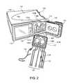
- FIG. 2is a perspective view of the PD cycler and PD cassette of the PD system of FIG. 1 .
- a door of the PD cycleris in the open position to show the inner surfaces of the PD cycler that interface with the PD cassette during use.
- FIG. 3is a perspective view of an open cassette compartment of the PD cycler of FIGS. 1 and 2 .
- FIG. 4is an exploded, perspective view of a magnetic actuator assembly of the PD system of FIG. 1 .
- FIGS. 5 and 6are perspective views of the PD cassette of the PD system of FIG. 1 , from a flexible membrane side of the PD cassette and from a rigid base side of the PD cassette, respectively.
- the PD cassetteincludes magnetically attractive dome-shaped members disposed in pump chambers formed between the membrane and the rigid base of the cassette.
- FIG. 7is an exploded, perspective view of the PD cassette of the PD system of FIG. 1 .
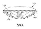
- FIG. 8is a perspective, cross-sectional view of one of the magnetically attractive dome-shaped members of the PD cassette of the PD system of FIG. 1 .
- FIG. 9is a perspective, cross-sectional view of the PD cassette of the PD system of FIG. 1 with a retention cover positioned over the pump chambers to hold the magnetically attractive dome-shaped members in place during shipping.
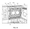
- FIG. 10is a partial perspective view of the PD cassette in the cassette compartment of the PD cycler of the PD system of FIG. 1 .
- FIGS. 11A-11Care diagrammatic cross-sectional views of the PD cassette in the cassette compartment of the PD cycler of the PD system of FIG. 1 , during different phases of operation.
- FIGS. 12-16illustrate various magnet arrangements for the actuators of the PD cycler of the PD system of FIG. 1 .
- FIG. 17is an exploded perspective view of an alternative magnetically attractive dome-shaped member that includes an exposed magnetic plate and can be used in the PD cassette of the PD system of FIG. 1 .
- FIG. 18is a perspective, cross-sectional view of an alternative PD cassette that includes a magnetically attractive dome-shaped member disposed in a fluid pump chamber of the PD cassette where the member includes feet that engage slots formed in a base of the PD cassette to hold the member in a central portion of the fluid pump chamber.
- FIG. 19is a cross-sectional view of the fluid pump chamber of the PD cassette of FIG. 18 .
- FIGS. 20A and 20Bare diagrammatic cross-sectional views of a PD cycler that includes decoupling posts, during and after treatment, respectively.
- FIG. 21is a perspective view of a PD cycler and PD cassette of another PD system.
- a door of the PD cycleris shown in the open position to expose magnetic, dome-shaped piston heads of the PD cycler that can be coupled to a magnetically attractive membrane of the PD cassette during use.
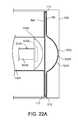
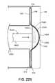
- FIGS. 22A-22Care diagrammatic cross-sectional views of the PD cassette in the cassette compartment of the PD cycler of the PD system of FIG. 21 , during different phases of operation.
- FIG. 23is a perspective, cross-sectional view of another type of magnetically attractive dome-shaped member that can be used in the PD cassette of the PD system of FIG. 1 .
- FIG. 24is a perspective, cross-sectional view of a further type of magnetically attractive dome-shaped member that can be used in the PD cassette of the PD system of FIG. 1 .
- a medical fluid cassette(e.g., a dialysis fluid cassette) includes a member disposed in a fluid pump chamber formed between a membrane and a base of the cassette.
- the medical fluid cassetteis configured to be disposed in a cassette compartment of a medical fluid pumping machine (e.g., a dialysis machine) in a manner such that an actuator of the medical fluid pumping machine is substantially aligned with the fluid pump chamber.
- the memberis attractive (e.g., magnetically attractive) to the actuator such that the actuator and the member can be coupled together with a flexible membrane of the cassette compressed therebetween.
- the actuatoris advanced to apply an inward force to the membrane and the member, forcing fluid out of the fluid pump chamber.
- the member and the actuatorDue to the attraction between the member and the actuator, the member and the actuator become coupled together as the actuator is advanced and the cassette membrane becomes compressed between the member and the actuator.
- the actuatoris subsequently retracted causing the member disposed in the fluid pump chamber to retract and apply an outward force to the membrane. This increases the volume of the fluid pump chamber, causing fluid to be drawn into the chamber.
- the volume of the fluid pump chambercan be increased by simply retracting the actuator.
- an external vacuumto be applied to the cassette membrane to increase the volume of the fluid pump chamber.
- a peritoneal dialysis (“PD”) system 100includes a PD cycler (also referred to as a PD machine) 102 seated on a cart 104 .
- the PD cycler 102includes a housing 106 , a door 108 , and a cassette interface 110 that mates with a disposable PD cassette 112 when the cassette 112 is disposed within a cassette compartment 114 formed between the cassette interface 110 and the closed door 108 .
- the cassette 112includes fluid pump chambers 138 A, 138 B formed between a rigid base 156 and a flexible membrane 140 (shown in FIGS. 5 and 7 ). Magnetically attractive dome-shaped members 161 A, 161 B are disposed in the fluid pump chambers 138 A, 138 B.
- a heater tray 116is positioned on top of the housing 106 .
- the heater tray 116is sized and shaped to accommodate a bag of dialysis solution (e.g., a five liter bag of dialysis solution).
- the PD cycler 102also includes a touch screen 118 and additional control buttons 120 that can be operated by a user (e.g., a patient) to allow, for example, set-up, initiation, and/or termination of a PD treatment.
- dialysis solution bags 122are suspended from fingers on the sides of the cart 104 , and a heater bag 124 is positioned on the heater tray 116 .
- the dialysis solution bags 122 and the heater bag 124are connected to the cassette 112 (shown in FIG. 2 ) via dialysis solution bag lines 126 and a heater bag line 128 , respectively.
- the dialysis solution bag lines 126can be used to pass dialysis solution from the dialysis solution bags 122 to the cassette 112 during use, and the heater bag line 128 can be used to pass dialysis solution back and forth between the cassette 112 and the heater bag 124 during use.
- a patient line 130 and a drain line 132are connected to the cassette 112 .
- the patient line 130can be connected to a patient's abdomen via a catheter and can be used to pass dialysis solution back and forth between the cassette 112 and the patient during use.
- the drain line 132can be connected to a drain or drain receptacle and can be used to pass dialysis solution from the cassette 112 to the drain or drain receptacle during use.
- FIG. 3shows a more detailed view of the cassette interface 110 and the door 108 of the PD cycler 102 .
- the PD cycler 102includes actuators (also referred to as pistons) 133 A, 133 B that contain multiple magnets 135 .
- the actuators 133 A, 133 Bare connected to a motor (e.g., a stepper motor) positioned in the housing 106 of the PD cycler 102 so that the actuators 133 A, 133 B can be axially moved within actuator access ports 136 A, 136 B formed in the cassette interface 110 .
- a motore.g., a stepper motor
- the magnetic actuators 133 A, 133 Bcan be coupled to the magnetically attractive dome-shaped members 161 A, 161 B of the cassette 112 when the cassette 112 is disposed within the cassette enclosure 114 during use such that the dome-shaped members 161 A, 161 B can be reciprocated along with the actuators 133 A, 133 B.
- FIG. 4illustrates an exploded view of the actuator 133 A. Only the actuator 133 A will be described here since the other actuator 133 B has the same construction and operates in the same way as the actuator 133 A.
- the actuator 133 Aincludes a magnet plate 137 A that has a concentric circular array of recesses 139 A in which the magnets 135 are disposed.
- a cap plate 141 Ais disposed over the back side of the magnet plate 137 A in order to hold the magnets 135 within the recesses 139 A of the magnet plate 137 A.
- An adaptor 143 Aincludes a threaded stem 145 A that is inserted through a central bore 147 A in the cap plate 141 A and matingly engages a threaded bore 149 A in the magnet plate 137 A to secure the cap plate 141 A to the magnet plate 137 A.
- a plunger shaft 151 A of the actuator 133 Ais secured at one end to the adapter 143 A and at its opposite end to the motor in the housing 106 of the PD cycler 102 . Any of various mechanical coupling techniques can be used to secure the plunger shaft 151 A to the adapter 143 A.
- any of various suitable connection mechanismssuch as lead screw mechanisms, ball screw mechanisms, or other gear-type mechanisms, can be used to connect the plunger shaft 151 A to the motor. Operation of the motor causes the actuator 133 A to reciprocate within the actuator access port 136 A formed in the cassette interface 110 (shown in FIG. 3 ).
- one magnet 135is disposed within each of the recesses 139 A to form one circular grouping of magnets located near the center of the magnet plate 137 A and another circular grouping of magnets positioned around a circumferential edge region of the magnet plate 137 A. Every other magnet around each of the substantially circular magnet groupings has opposite polarity such that circumferentially adjacent magnets within the groupings have opposite polarities. It has been found that this arrangement of alternating polarity advantageously decreases the magnetic field present external to the PD cycler 102 .
- the magnetic fieldtypically has a strength of less than 10 Gauss (e.g., less than 5 Gauss) at a distance of about 1.5 inches in front of the actuator 133 A.
- the magnet plate 137 A, the cap plate 141 A, the adapter 143 A, and the plunger shaft 151 Aare typically formed of one or more non-magnetic materials. In some implementations, these actuator components are formed of aluminum. Other metals, such as brass, bronze, non-magnetic stainless steel, and titanium, can alternatively or additional be used to form the magnet plate 137 A, the cap plate 141 A, the adapter 143 A, and/or the plunger shaft 151 A.
- certain plasticssuch as ABS, Delrin, polycarbonate, PEEK, fiber-reinforced PEEK, carbon fiber, nylon, Ultem, PVC, and PPC, can be used to form the magnet plate 137 A, the cap plate 141 A, the adapter 143 A, and/or the plunger shaft 151 A.
- the magnet plate 137 A and cap plate 141 A of the actuator 133 Agenerally have diameters that are substantially equal to the diameter of the associated dome-shaped member 161 A disposed within the pump chamber 138 A of the cassette 112 .
- the magnet plate 137 A and cap plate 141 Ahave diameters of about 1.0 inch to about 3.0 inch (e.g., about 2.0 inch).
- the magnet plate 137 Ahas a large enough thickness so that the recesses 139 A formed in the magnet plate 137 A can accommodate the magnets 135 .
- the front wall portion of the magnet plate 137 A that sits adjacent each magnet 135is sufficiently thin so that the magnetic force of the magnets 135 can penetrate through the front wall of the magnet plate 137 A and allow the actuator 133 A to be coupled to the dome-shaped member 161 A with a desired force (e.g., at least about 10 lbf, at least about 15 lbf, about 10 lbf to about 22 lbf).
- a desired forcee.g., at least about 10 lbf, at least about 15 lbf, about 10 lbf to about 22 lbf.
- the magnet plate 137 Ahas a thickness of about 0.20 inch to about 0.30 inch (e.g., about 0.25 inch), and the recesses formed in the magnet plate 137 A have diameters of about 0.35 inch to about 0.45 inch (e.g., about 0.38 inch) and depths of about 0.195 inch to about 0.295 inch (e.g., about 0.245 inch).
- the thickness of the front wall of the magnet plate 137 A in the areas overlying the recesses 139 Ais about 0.005 inch. Using such a thin wall in the areas overlying the recesses 139 A can help to ensure that a desired amount of magnetic force extends beyond the front face of the actuator 133 A.
- the magnets 135can be any of various different types of magnets that are together capable of providing the desired coupling force between the actuator 133 A and the dome-shaped member 161 A of the cassette 112 .
- the magnetsare formed of NdFeB and plated with NiCuNi.
- Each of the magnetscan have a diameter of about 0.345 inch to about 0.445 inch (e.g., about 0.375 inch) and a thickness of about 0.075 inch to about 0.175 inch (e.g., about 0.125 inch).
- Suitable magnetsare available from K&J Magnetics, Inc., under product number D62-N52.
- the magnetic actuators 133 A, 133 B of the PD cycler 102align with pump chambers 138 A, 138 B of the cassette 112 such that the magnetically attractive dome-shaped members 161 A, 161 B disposed in the chambers 138 A, 138 B become magnetically coupled to the actuators 133 A, 133 B with portions of the cassette membrane 140 that overlie the pump chambers 138 A, 138 B compressed between the actuators 133 A, 133 B and the dome-shaped members 161 A, 161 B.
- the actuators 133 A, 133 B, the dome-shaped members 161 A, 161 B, and the portions of the cassette membrane 140 compressed therebetweencan be advanced to decrease the volume defined by the pump chambers 138 A, 138 B and force dialysis solution out of the pump chambers 138 A, 138 B.
- the actuators 133 A, 133 B, the dome-shaped members 161 A, 161 B, and the portions of the cassette membrane 140 compressed therebetweencan then be retracted to decrease the volume defined by the pump chambers 138 A, 138 B and draw dialysis solution into the pump chambers 138 A, 138 B.
- the PD cycler 102also includes multiple inflatable members 142 positioned within inflatable member access ports 144 in the cassette interface 110 .
- the inflatable members 142align with depressible dome regions 146 of the cassette 112 (shown in FIGS. 5-7 ) when the cassette 112 is positioned within the cassette compartment 114 . While only one of the inflatable members 142 is labeled in FIG. 3 , it should be understood that the PD cycler 102 includes an inflatable member 142 associated with each of the depressible dome regions 146 of the cassette 112 .
- the inflatable members 142act as valves to direct dialysis solution through the cassette 112 in a desired manner during use.
- the inflatable members 142bulge outward beyond the surface of the cassette interface 110 and into contact with the depressible dome regions 146 of the cassette 112 when inflated, and retract into the inflatable member access ports 144 and out of contact with the cassette 112 when deflated.
- certain fluid flow paths within the cassette 112can be occluded.
- dialysis solutioncan be pumped through the cassette 112 by actuating the actuators 133 A, 133 B, and can be guided along desired flow paths within the cassette 112 by selectively inflating and deflating the inflatable members 142 .
- locating pins 148extend from the cassette interface 110 .
- the cassette 112can be loaded onto the cassette interface 110 by positioning the top portion of the cassette 112 under the locating pins 148 and pushing the bottom portion of the cassette 112 toward the cassette interface 110 .
- the cassette 112is dimensioned to remain securely positioned between the locating pins 148 and a lower ledge 150 extending from the cassette interface 110 to allow the door 108 to be closed over the cassette 112 .
- the locating pins 148help to ensure that the pump chambers 138 A, 138 B of the cassette 112 are aligned with the actuators 133 A, 133 B when the cassette 112 is positioned in the cassette compartment 114 between the closed door 108 and the cassette interface 110 .
- the door 108defines recesses 152 A, 152 B that substantially align with the actuators 133 A, 133 B when the door 108 is in the closed position.
- hollow projections 154 A, 154 B of the cassette 112(shown in FIG. 6 ), inner surfaces of which cooperate with the membrane 140 to form the pump chambers 138 A, 138 B, fit within the recesses 152 A, 152 B.
- the door 108further includes a pad that can be inflated during use to compress the cassette 112 between the door 108 and the cassette interface 110 .
- the portions of the door 108 forming the recesses 152 A, 152 Bsupport the projections 154 A, 154 B and the planar surface of the door 108 supports the other regions of the cassette 112 .
- the door 108can counteract the forces applied by the actuators 133 A, 133 B and the inflatable members 142 and thus allows the actuators 133 A, 133 B to depress the portions of the membrane 140 overlying the pump chambers 138 A, 138 B and similarly allows the inflatable members 142 to actuate the depressible dome regions 146 on the cassette 112 .
- the PD cycler 102includes various other features not described in detail herein. Further details regarding the PD cycler 102 and its various components can be found in U.S. Patent Application Publication No. 2007/0112297, which is incorporated by reference herein.
- FIGS. 5 and 6are perspective views from the membrane side and rigid base side, respectively, of the cassette 112
- FIG. 7is an exploded, perspective view of the cassette 112
- the cassette 112includes the tray-like rigid base 156 , the flexible membrane 140 , which is attached to the periphery of the base 156 , and the magnetically attractive dome-shaped members 161 A, 161 B, which are disposed in recessed regions 163 A, 163 B formed by the hollow projections 154 A, 154 B of the base 156 .
- the recessed regions 163 A, 163 B of the base 156cooperate with the flexible membrane 140 to form the pump chambers 138 A, 138 B when the cassette 112 is compressed between the door 108 and the cassette interface 110 of the PD cycler 102 resulting in the flexible membrane 140 being pressed against raised ridges 165 A, 165 B that extend from the base 156 and surround the recessed regions 163 A, 163 B.
- the volumes between the membrane 140 and the hollow projections 154 A, 154 B that form the recessed regions 163 A, 163 B of the base 156serve as the pump chambers 138 A, 138 B.
- dome-shaped members 161 A, 161 Bare attached (e.g., thermally or adhesively bonded) to the inner surface of portions of the membrane 140 overlying the pump chambers 138 A, 138 B.
- the dome-shaped members 161 A, 161 Bare shaped to generally conform to the recessed regions 163 A, 163 B of the base 156 of the cassette 112 .
- the dome-shaped members 161 A, 161 Binclude internal magnetically attractive, steel plates 162 A, 162 B that cause the dome-shaped members 161 A, 161 B to be attracted to the magnetic actuators 133 A, 133 B of the PD cycler 102 . Due to this construction, the actuators 133 A, 133 B can be used to advance the dome-shaped members 161 A, 161 B toward the base 156 and thus decrease the volume of the pump chambers 138 A, 138 B, or to retract the dome-shaped members 161 A, 161 B away from the base 156 of the cassette 112 and thus decrease the volume of the pump chambers 138 A, 138 B.
- Decreasing the volume of the pump chambers 138 A, 138 Bcauses fluid (e.g., about 12-13 ml of fluid) to be expelled from the pump chambers 138 A, 138 B via fluid outlet ports 169 A, 169 B, while increasing the volume of the pump chambers 138 A, 138 B causes fluid (e.g., about 12-13 ml of fluid) to be drawn into the pump chambers 138 A, 138 B via fluid inlet ports 171 A, 171 B.
- fluide.g., about 12-13 ml of fluid
- FIG. 8shows a perspective, cross-sectional view of the dome-shaped member 161 A.
- the other dome-shaped member 161 Bis identical to the illustrated dome-shaped member 161 A and thus, for simplicity, is not shown here.
- the dome-shaped member 161 Aincludes a dome-shaped polypropylene portion 173 A, a polypropyline bio-fine film 175 A, and the magnetically attractive steel plate 162 A sealed between the polypropylene portion 173 A and the polypropylene film 175 A.
- the polypropylene materials used for the dome-shaped portion 173 A and the film 175 Aare biocompatible. Due to the construction of the dome-shaped member 161 A, bodily fluids of a patient will only contact the biocompatible polypropylene portion 173 A and the biocompatible polypropylene film 175 A, and not the steel plate 162 A.
- a pre-form of the dome-shaped portion 173 Ais first formed using an injection molding technique.
- the steel plate 162 Ais then positioned within a recess of the pre-form of the dome-shaped portion 173 A, and the assembly of steel plate 162 A and the preform are subjected to an overmolding technique in which the steel plate 162 A is disposed and securely held within a mold into which molten polypropylene is injected.
- the injected molten polypropyleneis allowed to solidify and form the remainder of the dome-shaped portion 173 A, which partially encapsulates the steel plate 162 A.
- the circumferential region of the steel plate 162 Aas shown in FIG.
- the polypropylene film 175 Ais then placed over the steel plate 162 A and the dome-shaped portion 173 A, and the circumferential edge region of the polypropylene film 175 A is laser welded to the circumferential edge region of the dome-shaped polypropylene portion 173 A. This laser weld creates a liquid-tight seal and thus seals the steel plate 162 A in a liquid-tight manner between the polypropylene film 175 A and the dome-shaped polypropylene portion 173 A.
- any of various mechanical coupling techniquessuch as screwing the steel plate 162 A to the dome-shaped polypropylene portion 173 A and snap fitting these components together, can be used.
- a laser weldto secure the polypropylene film 175 A to the dome-shaped polypropylene portion 173 A
- other thermal bonding techniquesthat create a suitable bond can be used.
- dome-shaped portion 173 A and the film 175 Ahave been described as being formed of polypropylene, one or more other biocompatible polymers can alternatively or additionally be used.
- one or both of these componentsare formed of polyoxymethylene (marketed under the trade name Delrin available from Dupont of Wilmington, Del.).
- Other suitable biocompatible polymersinclude polytetrafluoroethylene (PTFE), polyvinyl chloride, polycarbonate, and polysulfone.
- the magnetically attractive plate 162 Ahas been described as being formed of steel, one or more other ferromagnetic materials can alternatively or additionally be used.
- Other examples of ferromagnetic materials from which the magnetically attractive plate 162 A can be formedinclude stainless steel, iron, nickel, and cobalt.
- the thickness of the magnetically attractive plate 162 Adepends on the type of material from which the magnetically attractive plate 162 A is formed and the desired magnetic force to be applied between the plate 162 A and the actuator 133 A. In some implementations, the plate 162 A has a thickness of about 0.020 inch to about 0.060 inch (e.g., about 0.040 inch). In certain implementations, the magnetically attractive plate 162 A is a magnet.
- the membrane 140when compressed against the base 156 , also cooperates with a series of raised ridges 167 extending from the base 156 to form a series of fluid pathways 158 and to form the multiple, depressible dome regions 146 , which are widened portions (e.g., substantially circular widened portions) of the fluid pathways 158 .
- the dialysis solutionflows to and from the pump chambers 138 A, 138 B through the fluid pathways 158 and dome regions 146 .
- the membrane 140can be deflected to contact the surface of the base 156 from which the raised ridges 167 extend.
- Such contactcan substantially impede (e.g., prevent) the flow of dialysis solution along the region of the pathway 158 associated with that dome region 146 during use.
- the flow of dialysis solution through the cassette 112can be controlled through the selective depression of the depressible dome regions 146 by selectively inflating the inflatable members 142 of the PD cycler 102 .
- the rigidity of the base 156helps to hold the cassette 112 in place within the cassette compartment 114 of the PD cycler 102 and to prevent the base 156 from flexing and deforming in response to forces applied to the projections 154 A, 154 B by the dome-shaped members 161 A, 161 B and in response to forces applied to the planar surface of the base 156 by the inflatable members 142 .
- the base 156can be formed of any of various relatively rigid materials.
- the base 156is formed of one or more polymers, such as polypropylene, polyvinyl chloride, polycarbonate, polysulfone, and other medical grade plastic materials.
- the base 156is formed of one or more metals or alloys, such as stainless steel.
- the base 156can alternatively be formed of various different combinations of the above-noted polymers and metals.
- the base 156can be formed using any of various different techniques, including machining, molding, and casting techniques.
- fluid line connectors 160are positioned along the bottom edge of the cassette 112 .
- the fluid pathways 158 in the cassette 112lead from the pumping chambers 138 A, 138 B to the various connectors 160 .
- the connectors 160are positioned asymmetrically along the width of the cassette 112 .
- the asymmetrical positioning of the connectors 160helps to ensure that the cassette 112 will be properly positioned in the cassette compartment 114 with the membrane 140 of the cassette 112 facing the cassette interface 110 .
- the connectors 160are configured to receive fittings on the ends of the dialysis solution bag lines 126 , the heater bag line 128 , the patient line 130 , and the drain line 132 .
- One end of the fittingcan be inserted into and bonded to its respective line and the other end can be inserted into and bonded to its associated connector 160 .
- the connectors 160allow dialysis solution to flow into and out of the cassette 112 during use.
- the membrane 140is attached to the periphery of the base 156 .
- the portion of the membrane 140 overlying the central portion of the base 156is typically not attached to the base 156 . Rather, this portion of the membrane 140 sits loosely atop the raised ridges 165 A, 165 B, and 167 extending from the planar surface of the base 156 .
- Any of various attachment techniquessuch as adhesive bonding and thermal bonding, can be used to attach the membrane 140 to the periphery of the base 156 .
- the thickness and material(s) of the membrane 140are selected so that the membrane 140 has sufficient flexibility to flex toward the base 156 in response to the force applied to the membrane 140 by the actuators 133 A, 133 B and the inflatable members 142 .
- the membrane 140is about 0.100 micron to about 0.150 micron in thickness. However, other thicknesses may be sufficient depending on the type of material used to form the membrane 140 .
- the membrane 140includes a three-layer laminate.
- inner and outer layers of the laminateare formed of a compound that is made up of 60 percent Septon® 8004 thermoplastic rubber (i.e., hydrogenated styrenic block copolymer) and 40 percent ethylene
- a middle layeris formed of a compound that is made up of 25 percent Tufted® H1062 (SEBS: hydrogenated styrenic thermoplastic elastomer), 40 percent Engage® 8003 polyolefin elastomer (ethylene octene copolymer), and 35 percent Septon® 8004 thermoplastic rubber (i.e., hydrogenated styrenic block copolymer).
- SEBShydrogenated styrenic thermoplastic elastomer
- Engage® 8003 polyolefin elastomerethylene octene copolymer
- 35 percent Septon® 8004 thermoplastic rubberi.e., hydrogenated styrenic block copolymer.
- the membranecan alternatively include more or fewer layers and/or
- the rigid base 156 , the membrane 140 , and the dome-shaped members 161 A, 161 Bare typically formed separately and then assembled to make the cassette 112 .
- the dome-shaped members 161 A, 161 Bare attached (e.g., welded) to the membrane 140 and then inserted into the recesses 163 A, 163 B formed by the hollow protrusions 154 A, 154 B of the rigid base 156 .
- the membrane 140is then attached to the perimeter of the rigid base 156 .
- a rigid cover 177is snapped onto the cassette 112 to hold the dome-shaped members 161 A, 161 B in place within the pump chambers 138 A, 138 B.
- the cover 177is a rigid polymeric member that has resilient tabs 179 that fit around side edge regions of the cassette 112 to firmly hold the cover against the cassette 112 .
- the cover 177includes projections 181 A, 181 B that extend from a relatively planar section 183 of the cover 177 and are sized and shaped to fit within the recessed regions 163 A, 163 B of the base 156 of the cassette 112 .
- the projections 181 A, 181 Bextend a sufficient distance from the planar section 183 of the cover 177 to press the dome-shaped members 161 A, 161 B of the cassette 112 against the base 156 of the cassette 112 when the cover is snapped onto the cassette 112 .
- the dome-shaped members 161 A, 161 Bare prevented from moving around within the pump chambers 138 A, 138 B and potentially becoming damaged.
- the door 108 of the PD cycler 102is opened to expose the cassette interface 110 , and the cassette 112 is positioned with its membrane 140 adjacent to the cassette interface 110 .
- the cassette 112is positioned such that the pump chambers 138 A, 138 B of the cassette 112 are aligned with the actuators 133 A, 133 B.
- the cassette 112is positioned between the locating pins 148 and the lower ledge 150 extending from the cassette interface 110 .
- the asymmetrically positioned connectors 160 of the cassetteact as keying features to reduce the likelihood that the cassette 112 will be installed with the membrane 140 facing in the wrong direction (e.g., facing outward toward the door 108 ).
- the locating pins 148can be dimensioned to be less than the maximum protrusion of the projections 154 A, 154 B such that the cassette 112 cannot contact the locating pins 148 if the membrane 140 is facing outward toward the door 108 .
- the actuators 133 A, 133 Bare typically retracted completely into the actuator access ports 136 A, 136 B. This positioning of the actuators 133 A, 133 B can reduce the likelihood of damage to the actuators 133 A, 133 B during installation of the cassette 112 . In addition, retracting the actuators 133 A, 133 B into the access ports 136 A, 136 B helps to prevent the actuators 133 A, 133 B from being prematurely coupled to the dome-shaped members 161 A, 161 B in the pump chambers 138 A, 138 B of the cassette 112 during insertion of the cassette 112 into the cassette enclosure 114 .
- FIGS. 11A-11Cillustrate the pump chamber 138 A and its associated dome-shaped member 161 A and actuator 133 A throughout different phases of operation.
- the other dome-shaped member 161 B and actuator 133 Boperate in a similar manner to pump dialysis solution to and from the other pump chamber 138 B and thus, for simplicity, the operation of those components will not be separately described.
- FIG. 11AWith the cassette 112 positioned adjacent to the cassette interface 110 , the door 108 is closed over the cassette 112 such that the cassette 112 is contained within the cassette compartment 114 between the door 108 and the cassette interface 110 . An inflatable pad within the door 108 is then inflated to compress the cassette 112 between the door 108 and the cassette interface 110 .
- This compression of the cassette 112holds the projections 154 A, 154 B of the cassette 112 in the recesses 152 A, 152 B of the door 108 and presses the membrane 140 tightly against the raised ridges 165 A, 165 B, 167 extending from the planar surface of the rigid base 156 to form the enclosed fluid pathways 158 , dome regions 146 , and pump chambers 138 A, 138 B (shown in FIGS. 5 and 6 ).
- the actuator 133 Ais advanced toward the cassette 112 such that the magnetic actuator 133 A becomes coupled to the magnetically attractive dome-shaped member 161 A in the pump chamber 138 A. Because the dome-shaped member 161 A is attached to the membrane 140 in a manner such that the dome-shaped member 161 A is centered within the pump chamber and because the cassette 112 is maintained in a desired position relative to the cassette interface 110 of the PD cycler 102 , the actuator 133 A is properly aligned with the dome-shaped member 161 A as the actuator 133 A is advanced.
- the actuator 133 A and the dome-shaped member 161 Abecome properly coupled by simply advancing the actuator 133 A.
- the actuatoris further advanced to deform the membrane 140 and force the dome-shaped member 161 A toward the rigid base 156 of the cassette 112 .
- the volume of the pump chamber 138 Adecreases, causing dialysis solution to be expelled from the pump chamber 138 A via the fluid pathways 158 of the cassette 112 (shown in FIGS. 5-7 ).
- the actuator 133 Ais again retracted, as shown in FIG. 11C .
- the magnetic coupling of the dome-shaped member 161 Acauses the dome-shaped member 161 A to move the membrane 140 in the same direction as the retracting actuator 133 A, thereby increasing the volume of the pump chamber 138 A and generating vacuum pressure of about 150 mbar to about 200 mbar within the pump chamber 138 A.
- dialysis solutionis drawn into the pump chamber 138 A of the cassette 112 via the fluid pathways 158 of the cassette 112 (shown in FIGS. 5-7 ).
- the dialysis solutioncan then be forced out of the pump chamber 138 A by again returning the actuator 133 A to the position shown in FIG. 11B , causing the membrane 140 and the dome-shaped member 161 A to move toward the rigid base 156 and thus decreasing the volume of the pump chambers 138 A, 138 B.
- the actuators 133 A, 133 Bare reciprocated to sequentially alter the volume of each of the pump chambers 138 A, 138 B.
- the other actuator head 134 Bis retracted, and vice versa.
- dialysis solutionis expelled from the pump chamber 138 A at the same time that dialysis solution is drawn into the pump chamber 138 B, and vice versa.
- certain inflatable members 142 of the PD cycler 102can be selectively inflated to direct the pumped dialysis solution along desired pathways in the cassette 112 .
- the patient line 130is connected to a patient's abdomen via a catheter, and the drain line 132 is connected to a drain or drain receptacle.
- the PD treatmenttypically begins by emptying the patient of spent dialysis solution that remains in the patient's abdomen from the previous treatment.
- the pump of the PD cycler 102is activated to cause the actuators 133 A, 133 B to reciprocate and selected inflatable members 142 are inflated to cause the spent dialysis solution to be drawn into the pump chambers 138 A, 138 B of the cassette 112 from the patient and then pumped from the pump chambers 138 A, 138 B to the drain via the drain line 132 .
- heated dialysis solutionis transferred from the heater bag 124 to the patient.
- the pump of the PD cycler 102is activated to cause the actuators 133 A, 133 B to reciprocate and certain inflatable members 142 of the PD cycler 102 are inflated to cause the spent dialysis solution to be drawn into the pump chambers 138 A, 138 B of the cassette 112 from the heater bag 124 via the heater bag line 128 and then pumped from the pump chambers 138 A, 138 B to the patient via the patient line 130 .
- the dialysis solutionis allowed to dwell within the patient for a period of time. During this dwell period, toxins cross the peritoneum into the dialysis solution from the patient's blood. As the dialysis solution dwells within the patient, the PD cycler 102 prepares fresh dialysate for delivery to the patient in a subsequent cycle. In particular, the PD cycler 102 pumps fresh dialysis solution from one of the four full dialysis solution bags 122 into the heater bag 124 for heating.
- the pump of the PD cycler 102is activated to cause the actuators 133 A, 133 B to reciprocate and certain inflatable members 142 of the PD cycler 102 are inflated to cause the dialysis solution to be drawn into the pump chambers 138 A, 138 B of the cassette 112 from the selected dialysis solution bag 122 via its associated line 126 and then pumped from the pump chambers 138 A, 138 B to the heater bag 124 via the heater bag line 128 .
- the spent dialysis solutionis pumped from the patient to the drain.
- the heated dialysis solutionis then pumped from the heater bag 124 to the patient where it dwells for a desired period of time.
- These stepsare repeated with the dialysis solution from two of the three remaining dialysis solution bags 122 .
- the dialysis solution from the last dialysis solution bag 122is typically delivered to the patient and left in the patient until the subsequent PD treatment.
- dialysis solutionhas been described as being pumped into the heater bag 124 from a single dialysis solution bag 122
- dialysis solutioncan alternatively be pumped into the heater bag 124 from multiple dialysis solution bags 122 .
- Such a techniquemay be advantageous, for example, where the dialysis solutions in the bags 122 have different concentrations and a desired concentration for treatment is intermediate to the concentrations of the dialysis solution in two or more of the bags 122 .
- the actuators 133 A, 133 Bare retracted away from the cassette 112 to a sufficient distance to decouple the actuators 133 A, 133 B and the dome-shaped members 161 A, 161 B of the cassette 112 .
- the dome-shaped members 161 A, 161 Bretract along with the actuators 133 A, 133 B and cause the membrane 140 to stretch.
- the resistance applied to the dome-shaped members 161 A, 161 Bincreases until eventually the resistive force applied to the dome-shaped members 161 A, 161 B by the membrane exceeds the attractive force between the actuators 133 A, 133 B and the dome-shaped members 161 A, 161 B, which causes the actuators 133 A, 133 B to become decoupled from the dome-shaped members 161 A, 161 B.
- the door 108 of the PD cycler 102is then opened and the cassette 112 is removed from the cassette compartment 114 and discarded.
- the PD system 100does not require a vacuum system to move the portions of the membrane 140 overlying the pump chambers 138 A, 138 B, a substantially airtight seal between the door 108 and the cassette interface 110 is typically not required.
- the door sealing mechanism of the PD cycler 102can be simpler and more cost effective.
- FIGS. 13-16While the magnets 135 of the actuators 133 A, 133 B have been described as being arranged in the roughly concentric circular pattern shown in FIG. 12 , other magnet arrangements are possible. Examples of other magnet arrangements are illustrated in FIGS. 13-16 . In each of FIGS. 13-16 , the recesses 139 A of the magnet plate 137 A in which magnets 135 are disposed are shaded, and the recesses 139 A that do not contain magnets are unshaded. As shown, in each of the illustrated magnet configurations, the positive poles of some of the magnets face outward and the positive poles of other magnets face inward. It has been found that this type of arrangement helps to reduce the magnetic field to which users of the PD cycler 102 are likely to be exposed.
- these magnet arrangementscan result in a magnetic field of no more than about 10 Gauss (e.g., no more than about 5 Gauss) at a distance of about 1.5 inches from the actuator 133 A, 133 B while providing a magnetic force of at least about 10 lbf (e.g., at least about 15 lbf) with the dome-shaped member 161 A coupled thereto.
- the actuators 133 A, 133 Bcan be easily disassembled and re-assembled.
- the magnet arrangementscan be changed between uses to ensure that an optimal magnetic force is achieved between the actuators 133 A, 133 B and the dome-shaped members 161 A, 161 B.
- dome-shaped member 161 Ahas been described as including the film 175 A bonded around the perimeter of the dome-shaped portion 173 A to seal the magnetically attractive plate 162 A between the film 175 A and the dome-shaped portion 173 A
- the cassette membrane 140itself is bonded to the perimeter region of the dome-shaped portion 173 A in order to seal the magnetically attractive plate 162 A between the membrane 140 and the dome-shaped portion 173 A.
- dome-shaped member 161 Ahas been described as including the film 175 A bonded around the perimeter of the dome-shaped portion 173 A to seal the magnetically attractive plate 162 A between the film 175 A and the dome-shaped portion 173 A
- a thicker and more rigid polymeric membercan be used in place of the film 175 A.
- a dome-shaped member 661 Aincludes the magnetically attractive plate 162 A sealed between a dome-shaped polypropylene portion 673 A and a polypropylene cap 675 A.
- the polypropylene cap 675 Ais thicker and more rigid than the film 175 A and is, in many situations, more resistant than the film 175 A to tearing or other damage that may jeopardize the biocompatible seal formed around the magnetically attractive plate 162 A. Due to the thickness of the polypropylene cap 675 A, it is typically impractical to use laser welds or certain other thermal bonds to secure the polypropylene cap 675 A to the dome-shaped polypropylene portion 673 A. Instead, barbs 676 A extend from the polypropylene cap 675 A and into mating recesses 674 A in the dome-shaped polypropylene portion 673 A to mechanically secure the polypropylene cap 675 A to the dome-shaped polypropylene portion 673 A.
- the dome-shaped polypropylene member 673 Ais first injection molded.
- the magnetically attractive plate 162 Ais then disposed in a cavity formed in the dome-shaped polypropylene member 673 A, and the assembly of the magnetically attractive plate 162 A and the dome-shaped polypropylene member 673 A is then inserted into a mold into which molten polypropylene is injected to overmold the polypropylene cap 675 A.
- the injected molten polypropyleneflows into the recesses 674 A in the dome-shaped polypropylene portion 673 A.
- the barbs 676 Aare formed.
- the barbs 676 Amechanically connect the polypropylene cap 675 A to the dome-shaped polypropylene portion 673 A.
- the polypropylene of the cap 675 Abonds with the polypropylene of the dome-shaped portion 673 A to further secure the polypropylene cap 675 A to the dome-shaped polypropylene portion 673 A.
- the mold into which the molten polypropylene is injected to form the polypropylene cap 675 Ais configured to include a gap between the outer perimeter of the dome-shaped polypropylene portion 673 A and the inner surface of the mold.
- the molten polypropylenewhich will eventually solidify and form the cap, is allowed to flow around the outer perimeter of the dome-shaped portion 673 A and solidify to form a wall that wraps around the circumferential edge of the dome-shaped polypropylene portion 673 A and secures the cap to the dome-shaped portion 673 A.
- caps and the dome-shaped portionshave been described as being formed of polypropylene, it should be understood that these components can be formed of any of the various biocompatible polymeric materials discussed above with respect to the dome-shaped portion 173 A and the film 175 A.
- the dome-shaped memberis formed using an insert injection molding technique.
- a two-part moldis opened and a steel plate is positioned between the two mold parts.
- the mold partsare then brought together to form a dome-shaped cavity in which the steel plate is positioned.
- molten biocompatible resinis injected into the cavity so that the steel plate becomes encapsulated within the molten resin.
- the mold partsare again pulled apart and the dome-shaped member is removed.
- dome-shaped members 161 A, 661 Acan be used to form the dome-shaped members 161 A, 661 A.
- the polymeric portions 173 A, 175 A, 673 A, 675 A and the magnetic plate 162 Aare all separately made and then attached (e.g., thermally or adhesively bonded or mechanically assembled) to one another to form the dome-shaped members 161 A, 661 A.
- the magnetically attractive plateis coated with a biocompatible material, such as polytetrafluoroehtylene (PTFE), and the coated plate itself forms the rear surface of the dome-shaped members.
- a dome-shaped member 761 Aincludes a PTFE-coated steel plate 762 A that is secured to dome-shaped portion 773 A.
- the PTFE-coated steel plate 762 Asimply includes the steel plate 162 A described above with a PTFE coating 764 A that encapsulates the plate 162 A.
- the steel plate 162 Ais first coated with PTFE to form the coated plate 762 A.
- a pre-form of the dome-shaped portion 773 Ais then injection molded.
- the coated plate 762 Ais then placed within a recessed region of the pre-form of the dome-shaped portion 773 A, and the assembly of the coated plate 762 A and the pre-form are disposed in a mold into which molten polypropylene is injected.
- the molten polypropylenecovers the circumferential region of the coated plate 762 A and solidifies to encapsulate the circumferential region of the coated plate 762 A within polypropylene and thereby form the remainder of the dome-shaped polypropylene portion 773 A.
- a central portion of the rear surface of the coated plate 762 Aremains exposed.
- the coating of the coated plate 762 Ahas been described as being formed of PTFE, other types of coatings can alternatively or additionally be used. In certain implementations, for example, the coating is formed of gold or Parylene. Similarly, while the plate has been described as being formed of steel and the dome-shaped portion 763 A has been described as being formed polypropylene, those components can alternatively be formed of any of the various other materials described above with respect to the corresponding components in the dome-shaped members 161 A and 661 A.
- FIG. 17illustrates an exploded perspective view of an alternative dome-shaped member 261 , which includes a biocompatible, magnetically attractive plate 262 secured to a dome-shaped biocompatible, polymeric member 273 .
- the plate 262includes a threaded bore 264 that can matingly engage threads of a threaded stem 274 extending from the dome-shaped polymeric member 273 to secure the plate 262 and the dome-shaped member 273 together. Because the plate 262 is not encapsulated, it may be exposed to fluid within the pump chamber of the cassette that is to be delivered to a patient. Thus, the plate 262 is formed of a biocompatible material.
- the plate 262is formed of stainless steel, such as stainless steel 417, stainless steel 410, or stainless steel 17-4.
- stainless steelother types of magnetically attractive, biocompatible materials can be used to form the plate 262 of the dome-shaped member 261 .
- the plate 262can, for example, include a steel plate or magnet that is coated with a biocompatible material, such as PTFE, gold, or Parylene.
- a biocompatible coatingcan be applied over a non-biocompatible magnetically attractive material, such as steel.
- dome-shaped member 273has been described as being formed of a biocompatible polymeric material, biocompatible materials of other types, such as biocompatible metals, can alternatively or additionally be used.
- both the magnetic plate 262 and the dome-shaped member 273are formed of stainless steel.
- pump chambers 138 A, 138 Bhave been described as being sized to pump about 12-13 ml of fluid with each actuator stroke, the pump chambers 138 A, 138 B and the dome-shaped members 161 A, 161 B disposed in those chambers can be sized to pump different volumes of fluid. In certain implementations, for example, the pump chambers 138 A, 138 B are sized to pump about 25-30 ml of fluid per actuator stroke.
- the cassetteincludes members that are not attached to the cassette membrane 140 .
- the dome-shaped membersare provided with magnets that are attracted to the magnets of the actuators. As a result of the strong attraction between these magnets, the magnets can help to properly align the dome-shaped members within the pump chambers.
- a PD cassette 312includes a magnetically attractive member 361 B that is mechanically restrained within a pump chamber 338 B formed between a rigid base 356 and the membrane 140 to maintain proper alignment of the member 361 B within the pump chamber 338 B.
- a magnetically attractive member 361 A that is identical to the member 361 Bis typically positioned in an additional pump chamber 338 A formed between the rigid base 356 and the membrane 140 .
- the member 361 Ais not shown in the pump chamber 338 A in FIG. 18 in order to provide a clearer view of the portion of the rigid base 356 that forms the pump chamber 338 A, which is similar to the portion of the rigid base 356 that forms the pump chamber 338 B.
- the magnetically attractive member 361 Bincludes a dome-shaped portion 363 B that is similar in construction to the dome-shaped member 161 A described above.
- Four resilient legs 365 Bextend from the dome-shaped portion 363 B and sit within slots 367 B formed by the base 356 .
- the top surface of the member 361 Bis in contact with or in near contact with the membrane 140 when the member 361 B is in an uncompressed state. As a result, the resilient legs 365 B are retained in the slots 367 B of the base 356 .
- the cassette 312can be used in the PD cycler 102 in generally the same way as the cassettes described above.
- the resilient legs 367 B of the member 361 Bcollapse and allow the hemispherical portion 363 B of the member 361 B to come into contact with or into near contact with the base 356 .
- the resilient legs 367 Bcan, for example, collapse upon being subjected to a compression force of about two pounds or greater (e.g., about five pounds or greater).
- the volume of the pump chamber 338 Bdecreases as a result of this movement, causing fluid to be expelled from the pump chamber 338 B.
- the actuator 133 Bis subsequently retracted, and the magnetic coupling between the actuator 133 B and the magnetically attractive plate within the hemispherical portion 363 B of the member 361 causes the member 361 B to be refracted along with the actuator 133 B.
- the volume of the pump chamber 338 Bincreases as a result of this movement, causing fluid to be drawn into the pump chamber 338 B.
- FIGS. 20A and 20Bshow the operation of a PD cycler 402 that includes decoupling posts 410 and an actuator 433 A that has bores 412 that extend through a magnet plate 437 A and cap plate 441 A of the actuator 433 A.
- the bores 412are sized and arranged to receive the decoupling posts 410 of the PD cycler 402 .
- the PD cycler 402is substantially the same as the PD cycler 102 described above. As with the PD cycler 102 described above, the PD cycler 402 also includes a second actuator that is similar to the actuator 433 A.
- the cassette 112is disposed within a cassette enclosure 414 of the PD cycler 402 such that the actuators of the PD cycler 402 align with the pump chambers 138 A, 138 B of the cassette. For simplicity, only the operation of the actuator 433 A associated with the pump chamber 138 A is shown and described with respect to FIGS. 20A and 20B .
- the PD cycler 402is generally operated in the same manner as the PD cycler 102 described above. As shown in FIG. 20A , as the actuator 433 A is advanced to expel fluid from the pump chamber 138 A, the membrane 140 of the cassette 112 is not in contact with the decoupling posts 410 . Rather, the decoupling posts 410 terminate at points within the bores 412 of the actuator 433 A. As the actuator 433 A is reciprocated during use to draw fluid into and pump fluid out of the pump chamber 138 A, the decoupling posts 410 remain out of contact with the membrane 140 . Thus, fluid can be expelled from and drawn into the pump chamber 138 A without interference from the decoupling posts 410 .
- the actuator 433 AUpon completion of the treatment, the actuator 433 A is retracted into the actuator access port 136 A.
- the decoupling posts 410are held in a fixed position. As a result, as the actuator 433 A, the membrane 140 , and the dome-shaped member 161 A are together retracted, the ends of the decoupling posts 410 contact the membrane 140 and resist further axial movement of the membrane 140 and the dome-shaped member 161 A. Due to the bores 412 formed in the actuator 433 A, the actuator 433 A is able to be drawn proximal to the ends of the decoupling posts 410 . Continued retraction of the actuator 433 A causes the dome-shaped member 161 A to become decoupled from the magnets 135 of the actuator 433 A, as shown in FIG. 21B .
- the decoupling posts 410advantageously allow the actuator 433 A and the dome-shaped member 161 A to be decoupled from one another without excessively stretching the membrane 140 of the cassette 112 .
- magnetically attractive members and the pump chambers of the above-described cassetteshave been described as being dome-shaped, magnetically attractive members and pump chambers of other mating shapes can be used.
- the magnetically attractive members and pump chamberscan be cylindrical, rectangular, etc.
- the magnetically attractive members that are disposed within the cassette pump chambershave been described as including one or more biocompatible polymers, they can alternatively be formed of other types of biocompatible materials, such as biocompatible metals.
- the dome-shaped membersare formed entirely of stainless steel.
- the actuators of the PD cyclers described aboveinclude permanent magnets, other types of magnetic devices can be used.
- the actuatorsare equipped with electromagnetic devices.
- the magnetic coupling between the actuators and the members disposed within the pump chambers of the cassettecan be broken by simply turning off the current to the electromagnetic device.
- the magnets 135have been described as being contained in the actuators of the PD cycler and the members disposed within the pump chambers of the cassettes have been described as including magnetically attractive materials that can be attracted to the magnets in the actuators, in some implementations, the members disposed within the pump chambers contain the magnets and the actuators include the magnetically attractive materials that can be attracted to the magnets. In still other implementations, both the member disposed within the pump chambers and the actuators of the PD cycler contain magnets.
- a dialysis systemincludes a dialysis machine having magnetic actuators that are magnetically coupled directly to a magnetically attractive membrane that partially forms the pump chambers of the cassette.
- a PD system 500includes a PD cycler 502 having pistons (also referred to as actuators) 533 A, 533 B that include electromagnetic, dome-shaped piston heads 534 A, 534 B attached (e.g., engaged by mating threads, thermally bonded, adhesively bonded, snap fit, etc.) to piston shafts 543 A, 543 B.
- Each of the piston heads 534 A, 534 Bincludes a cavity in which an electromagnet is contained.
- Each of the piston heads 534 A, 534 Bcan, for example, include a rear end cap that can be secured to the front dome-shaped portion of the piston head to form the cavity in which the electromagnet is contained.
- the electromagnetcan be threadedly engaged with or otherwise attached to the front dome-shaped member of the piston head.
- a power sourcee.g., a battery or a mains power supply to which the PD cycler 502 is connected
- a power sourcecan be connected to the electromagnets in the piston heads 534 A, 534 B via lead lines such that current can be transmitted to the electromagnets.
- the magnetic field surrounding the piston heads 534 A, 534 Bis very weak such that little or no attraction is experienced between the piston heads 534 A, 534 B and magnetically attractive objects in close proximity to the piston heads 534 A, 534 B.
- a current flowing in a first direction through the electromagnetcreates a magnetic field causing magnets in close proximity to the piston heads 534 A, 534 B to be attracted to the piston heads 534 A, 534 B, and a current flowing in a second, opposite direction through the piston heads 534 A, 534 B creates a magnetic field causing magnets (of the same polarity as the magnets mentioned above) in close proximity to the piston heads 534 A, 534 B to be repelled away from the piston heads 534 A, 534 B.
- the piston heads 534 A, 534 Bare typically formed of stainless steel. However, other metals, such as aluminum, and certain polymeric materials can alternatively or additionally be used to the form the piston heads 534 A, 534 B.
- electromagnetAn example of a suitable electromagnet is the EM050-12-222 electromagnet, available from APW Company (Rockaway, N.J.). However, other types of electromagnets can alternatively or additionally be used.
- Each of the pistons 533 A, 533 Bis connected to a motor (e.g., a stepper motor) positioned in the housing 106 of the PD cycler 502 so that the pistons 533 A, 533 B can be axially moved within the access ports 136 A, 136 B formed in the cassette interface 110 of the PD cycler 502 .
- a motore.g., a stepper motor
- the PD cycler 502has generally the same structure as and operates in a similar manner to the PD cycler 102 described above.
- the PD system illustrated in FIG. 21also includes a PD cassette 512 that includes a magnetically attractive membrane 540 (shown in FIGS. 22A-22C ) attached to the base 156 of the cassette 512 . Similar to the membrane 140 described above, the magnetically attractive membrane 540 covers substantially the entire base 156 and is attached (e.g., thermally or adhesively bonded) only to the periphery of the base 156 .
- the magnetically attractive membrane 540is typically formed of the same materials as the membrane 140 but also includes an outer layer of magnetically attractive material.
- the outer layercan, for example, be a layer of magnetically attractive paint. The outer layer is typically restricted only to those portions of the membrane overlying the fluid pump chambers 538 A, 538 B.
- the outer layer of magnetically attractive materialcan alternatively be applied to the entire surface of the membrane.
- a suitable magnetically attractive paintis RUST-OLEUM® Specialty magnetic latex primer, available from RUST-OLEUM® Corporation (Vernon Hills, Ill.).
- the PD cassette 512does not include magnetically attractive dome-shaped members inside its pump chambers 538 A, 538 B. Instead, the pump chambers 538 A, 538 B are vacant, except for containing liquid during use. As described in greater detail below, when the electromagnetic piston heads 534 A, 534 B are magnetically activated, they can be coupled directly to the magnetically attractive membrane 540 of the cassette 512 such that the magnetically attractive membrane 540 can be reciprocated along with the piston heads 534 A, 534 B.
- the cassette 512is loaded into the cassette compartment 114 of the PD cycler 502 in much the same way that the cassette 112 was previously described as being loaded into the cassette compartment 114 of the PD cycler 102 .
- currentdoes not flow through the electromagnets 535 A, 535 B of the pistons 533 A, 533 B such that little or no magnetic attraction is experienced between the magnetic piston heads 534 A, 534 B and the magnetically attractive membrane 540 of the cassette 512 .
- the pistons 533 A, 533 Bare typically retracted completely into the access ports 136 A, 136 B to reduce the likelihood of damage to the membrane 540 during installation of the cassette 512 .
- Retracting the pistons 533 A, 533 B into the access ports 136 A, 136 Bcan also help to prevent the piston heads 534 A, 534 B from being prematurely coupled to the magnetically attractive membrane 540 during installation, which could result in the piston heads 534 A, 534 B being misaligned with respect to the pump chambers 538 A, 538 B and could lead to inaccurate fluid pumping.
- FIGS. 22A-22Cillustrate the portion of the cassette 512 including the pump chamber 538 A and its associated piston 533 A throughout different phases of operation.
- the other piston 533 B and pump chamber 538 Bcooperate in a similar manner to pump dialysis solution to and from the other pump chamber 538 B and thus, for simplicity, the operation of those components will not be separately described.
- FIG. 22AWith the cassette 512 positioned adjacent to the cassette interface 110 , the door 108 of the PD cycler 502 is closed over the cassette 512 such that the cassette 512 is contained within the cassette compartment 114 between the door 108 and the cassette interface 110 . An inflatable pad within the door 108 is then inflated to compress the cassette 512 between the door 108 and the cassette interface 110 .
- This compression of the cassette 512holds the projections 154 A, 154 B of the cassette 512 in the recesses 152 A, 152 B of the door 108 and presses the membrane 540 tightly against the raised ridges extending from the planar surface of the rigid base 156 to form the various fluid pathways and chambers of the cassette 512 .
- a currentis applied to the piston head 534 A to magnetically activate the piston head 534 A, and the piston 533 A is advanced toward the cassette 512 such that the piston head 534 A becomes coupled to the portion of the magnetically attractive membrane 540 overlying the pump chamber 538 A of the cassette 512 .
- the piston 533 Ais then further advanced to deform the membrane 540 toward the rigid base 156 of the cassette 512 , causing dialysis solution to be expelled from the pump chamber 538 A via the fluid pathways of the cassette 512 .
- the piston 533 Ais again retracted, as shown in FIG. 22C . Due to the magnetic coupling between the piston head 534 A and the membrane 540 , the membrane 540 is retracted along with the piston 533 A, thereby increasing the volume of the pump chamber 538 A and generating vacuum pressure of about 150 mbar to about 200 mbar within the pump chamber 538 A. As a result, dialysis solution is drawn into the pump chamber 538 A via the fluid pathways of the cassette 512 .
- This techniquecan be used to carry out a PD treatment in much the same way as described above with respect to the PD system 100 .
- the current applied to the electromagnets 535 A, 535 B in the piston heads 534 A, 534 Bis reverse, causing a repelling force between the piston heads 534 A, 534 B and the membrane 540 .
- Thisallows the user to easily remove the cassette 512 from the cassette compartment 114 with reduced risk of tearing the membrane 540 .
- piston heads 534 A, 534 Bhave been described as including electromagnets, permanently magnetic piston heads can alternatively or additionally be used. In such cases, permanent magnets, rather than electromagnets, can be contained in the cavities of the piston heads. In order to release the coupling between the permanently magnetic piston heads and the magnetically attractive membrane after treatment, the piston heads would be retracted a sufficient distance to overcome the magnetic coupling force.
- each of the piston heads 534 A, 534 Bhas been described as including a single magnet (electromagnet or permanent magnet), it should be understood that multiple magnets can be contained within the piston heads 534 A, 534 B to achieve a desired magnetic force.
- the membrane 540has been described as including an outer layer of magnetically attractive material, such as paint or primer, in certain implementations, the magnetically attractive material is incorporated into the body of the membrane.
- the magnetically attractive materialis incorporated into the body of the membrane.
- iron particlescan be suspended within the body of the membrane.
- membranes 140 , 540have been described as being attached only to the periphery of the base 156 of the cassettes 112 , 512 , in certain implementations the membranes 140 , 540 are also attached (e.g., thermally or adhesively bonded) to the raised features 165 A, 165 B, 167 extending from the planar surface of the base 156 .
- membranes 140 , 540have been described as covering substantially the entire surface of the base 156 of the cassettes 112 , 512 , membranes covering only the pump chambers can alternatively be used.
- the fluid pathways extending from the pump chambers of the cassettecan be provided by tubing that is fluidly connected to the pump chambers.
- cassettes discussed abovehave been described as having two pump chambers, the cassettes can alternatively have more or fewer than two pump chambers.
- each of the pump chambers of the cassettes described abovehas been described as including a fluid inlet port and a fluid outlet port, the pump chambers can alternatively include a single port that is used as both an inlet and an outlet.
- cassetteshave been described as being positioned between locating pins and a lower ledge extending from a cassette interface of the PD cycler in order to hold the cassette in a position such that the actuator heads align with the pump chambers of the cassette
- other techniques for ensuring that the actuator heads align with the pump chamberscan alternatively or additionally be used.
- the cassetteis placed against the door of the PD cycler with the hollow projections of the cassette disposed in recesses of the PD cycler's door. The cassette is held in this position by retainer clips attached to the door. Upon closing the door, the actuator heads of the PD cycler align with the pump chambers of the cassette.
- the PD cyclercan include other types of screens and user data entry systems.
- the cyclerincludes a display screen with buttons (e.g., feathertouch buttons) arranged on the console adjacent the display screen.
- buttonse.g., feathertouch buttons
- Certain buttonscan be arranged to be aligned with operational options displayed on the screen during use such that the user can select a desired operational option by pressing the button aligned with that operational option.
- Additional buttons in the form of arrow buttonscan also be provided to allow the user to navigate through the various display screens and/or the various items displayed on a particular screen.
- Other buttonscan be in the form of a numerical keypad to allow the user to input numerical values in order, for example, to input operational parameters.
- a select or enter buttoncan also be provided to allow the user to select an operational option to which the user navigated by using the arrow keys and/or to allow the user to enter values that the user inputted using the numerical keypad.
- doors of the PD cyclers described aboveare shown as being positioned on a front face of the PD cyclers, the doors can alternatively be positioned at various other locations on the PD cyclers.
- the doorscould be positioned on a top face of the PD cycler such that the cassette is slid into the cassette compartment in a substantially horizontal orientation instead of a substantially vertical orientation.
- the PD cyclers discussed aboveinclude inflatable pads in their doors to compress the cassette between the door and the cassette interface
- the PD cyclerscan alternatively or additionally include inflatable pads positioned behind the cassette interface.
- other mechanisms suitable for compressing the cassettecan be used.
- cassettes described abovehave been described as being part of a PD system, these types of cassettes can be used in any of various other types of cassette-based medical fluid pumping systems.
- Other examples of medical fluid pumping systems with which cassettes described herein can be usedinclude hemodialysis systems, blood perfusion systems, and intravenous infusion systems.
- cassetteshave been described as being used to pump dialysis solution
- other types of dialysis fluidscan be pumped through the cassettes.
- bloodcan be pumped through the cassettes.
- priming solutionssuch as saline
- any of various other types of medical fluidscan be pumped through the above-described cassettes depending on the type of medical fluid pumping machines with which the cassettes are used.
Landscapes
- Health & Medical Sciences (AREA)
- Heart & Thoracic Surgery (AREA)
- Urology & Nephrology (AREA)
- Emergency Medicine (AREA)
- Engineering & Computer Science (AREA)
- Hematology (AREA)
- Anesthesiology (AREA)
- Biomedical Technology (AREA)
- Vascular Medicine (AREA)
- Life Sciences & Earth Sciences (AREA)
- Animal Behavior & Ethology (AREA)
- General Health & Medical Sciences (AREA)
- Public Health (AREA)
- Veterinary Medicine (AREA)
- Mechanical Engineering (AREA)
- General Engineering & Computer Science (AREA)
- External Artificial Organs (AREA)
- Infusion, Injection, And Reservoir Apparatuses (AREA)
Abstract
Description
Claims (20)
Priority Applications (1)
| Application Number | Priority Date | Filing Date | Title |
|---|---|---|---|
| US13/994,286US9694125B2 (en) | 2010-12-20 | 2011-12-16 | Medical fluid cassettes and related systems and methods |
Applications Claiming Priority (3)
| Application Number | Priority Date | Filing Date | Title |
|---|---|---|---|
| US201061425050P | 2010-12-20 | 2010-12-20 | |
| PCT/US2011/065415WO2012087798A2 (en) | 2010-12-20 | 2011-12-16 | Medical fluid cassettes and related systems and methods |
| US13/994,286US9694125B2 (en) | 2010-12-20 | 2011-12-16 | Medical fluid cassettes and related systems and methods |
Publications (2)
| Publication Number | Publication Date |
|---|---|
| US20140018728A1 US20140018728A1 (en) | 2014-01-16 |
| US9694125B2true US9694125B2 (en) | 2017-07-04 |
Family
ID=45476642
Family Applications (1)
| Application Number | Title | Priority Date | Filing Date |
|---|---|---|---|
| US13/994,286Active2034-07-13US9694125B2 (en) | 2010-12-20 | 2011-12-16 | Medical fluid cassettes and related systems and methods |
Country Status (3)
| Country | Link |
|---|---|
| US (1) | US9694125B2 (en) |
| EP (1) | EP2654825B1 (en) |
| WO (1) | WO2012087798A2 (en) |
Cited By (5)
| Publication number | Priority date | Publication date | Assignee | Title |
|---|---|---|---|---|
| US9861733B2 (en) | 2012-03-23 | 2018-01-09 | Nxstage Medical Inc. | Peritoneal dialysis systems, devices, and methods |
| US9907897B2 (en) | 2011-03-23 | 2018-03-06 | Nxstage Medical, Inc. | Peritoneal dialysis systems, devices, and methods |
| US10426882B2 (en) | 2003-12-16 | 2019-10-01 | Baxter International Inc. | Blood rinseback system and method |
| US11207454B2 (en) | 2018-02-28 | 2021-12-28 | Nxstage Medical, Inc. | Fluid preparation and treatment devices methods and systems |
| US12048791B2 (en) | 2017-06-24 | 2024-07-30 | Nxstage Medical, Inc. | Peritoneal dialysis fluid preparation and/or treatment devices methods and systems |
Families Citing this family (70)
| Publication number | Priority date | Publication date | Assignee | Title |
|---|---|---|---|---|
| WO2006086490A1 (en) | 2005-02-07 | 2006-08-17 | Medtronic, Inc. | Ion imbalance detector |
| US9399091B2 (en) | 2009-09-30 | 2016-07-26 | Medtronic, Inc. | System and method to regulate ultrafiltration |
| US9848778B2 (en) | 2011-04-29 | 2017-12-26 | Medtronic, Inc. | Method and device to monitor patients with kidney disease |
| US9456755B2 (en) | 2011-04-29 | 2016-10-04 | Medtronic, Inc. | Method and device to monitor patients with kidney disease |
| US9561316B2 (en) | 2011-04-29 | 2017-02-07 | Medtronic, Inc. | Intersession monitoring for blood fluid removal therapy |
| CN103889481B (en) | 2011-08-02 | 2016-03-09 | 美敦力公司 | Hemodialysis system with flow path with controlled compliance volume |
| EP2744537B1 (en) | 2011-08-16 | 2018-01-24 | Medtronic, Inc. | Modular hemodialysis system |
| EP2800592B1 (en) | 2012-01-04 | 2019-03-06 | Medtronic Inc. | Multi-staged filtration system for blood fluid removal |
| US10905816B2 (en) | 2012-12-10 | 2021-02-02 | Medtronic, Inc. | Sodium management system for hemodialysis |
| US9713666B2 (en) | 2013-01-09 | 2017-07-25 | Medtronic, Inc. | Recirculating dialysate fluid circuit for blood measurement |
| US9707328B2 (en) | 2013-01-09 | 2017-07-18 | Medtronic, Inc. | Sorbent cartridge to measure solute concentrations |
| US11565029B2 (en) | 2013-01-09 | 2023-01-31 | Medtronic, Inc. | Sorbent cartridge with electrodes |
| US11154648B2 (en) | 2013-01-09 | 2021-10-26 | Medtronic, Inc. | Fluid circuits for sorbent cartridge with sensors |
| US9623164B2 (en) | 2013-02-01 | 2017-04-18 | Medtronic, Inc. | Systems and methods for multifunctional volumetric fluid control |
| US10543052B2 (en) | 2013-02-01 | 2020-01-28 | Medtronic, Inc. | Portable dialysis cabinet |
| US10010663B2 (en) | 2013-02-01 | 2018-07-03 | Medtronic, Inc. | Fluid circuit for delivery of renal replacement therapies |
| US9526822B2 (en) | 2013-02-01 | 2016-12-27 | Medtronic, Inc. | Sodium and buffer source cartridges for use in a modular controlled compliant flow path |
| US10850016B2 (en) | 2013-02-01 | 2020-12-01 | Medtronic, Inc. | Modular fluid therapy system having jumpered flow paths and systems and methods for cleaning and disinfection |
| US9144640B2 (en) | 2013-02-02 | 2015-09-29 | Medtronic, Inc. | Sorbent cartridge configurations for improved dialysate regeneration |
| US9827361B2 (en) | 2013-02-02 | 2017-11-28 | Medtronic, Inc. | pH buffer measurement system for hemodialysis systems |
| US9714650B2 (en)* | 2013-06-11 | 2017-07-25 | Matthew G. Morris, Jr. | Pumping system |
| DE102013013415A1 (en)* | 2013-08-09 | 2015-02-12 | Fresenius Medical Care Deutschland Gmbh | cassette module |
| USD729938S1 (en) | 2013-10-24 | 2015-05-19 | Fresenius Medical Care Holdings, Inc. | Piston head for a peritoneal dialysis cycler |
| US10076283B2 (en) | 2013-11-04 | 2018-09-18 | Medtronic, Inc. | Method and device to manage fluid volumes in the body |
| US9884145B2 (en) | 2013-11-26 | 2018-02-06 | Medtronic, Inc. | Parallel modules for in-line recharging of sorbents using alternate duty cycles |
| US10537875B2 (en) | 2013-11-26 | 2020-01-21 | Medtronic, Inc. | Precision recharging of sorbent materials using patient and session data |
| EP3073911B8 (en) | 2013-11-27 | 2025-09-03 | Mozarc Medical US LLC | Precision dialysis monitoring and synchonization system |
| DE102014103506A1 (en)* | 2014-03-14 | 2015-09-17 | Fresenius Medical Care Deutschland Gmbh | Blood treatment cassette with dished foil valve and blood treatment device |
| CN106165509B (en)* | 2014-03-28 | 2020-01-10 | Lg电子株式会社 | Method for device-to-device (D2D) operation performed by terminal in wireless communication system and terminal using the same |
| JP2015213596A (en)* | 2014-05-09 | 2015-12-03 | ニプロ株式会社 | Water removal pump for portable blood dialysis |
| USD724740S1 (en)* | 2014-06-05 | 2015-03-17 | Deka Products Limited Partnership | Enclosure for a peritoneal dialysis device |
| USD725780S1 (en)* | 2014-06-05 | 2015-03-31 | Deka Products Limited Partnership | Heater tray for a peritoneal dialysis device |
| USD725782S1 (en) | 2014-06-05 | 2015-03-31 | Deka Products Limited Partnership | Bottom panel of an enclosure |
| USD725781S1 (en)* | 2014-06-05 | 2015-03-31 | Deka Products Limited Partnership | Container holder for a peritoneal dialysis device |
| USD724741S1 (en)* | 2014-06-05 | 2015-03-17 | Deka Products Limited Partnership | Enclosure skirt for a peritoneal dialysis device |
| USD724742S1 (en) | 2014-06-05 | 2015-03-17 | Deka Products Limited Partnership | Rear panel of an enclosure |
| USD725277S1 (en)* | 2014-06-05 | 2015-03-24 | Deka Products Limited Partnership | Door for a peritoneal dialysis device |
| WO2015199768A1 (en) | 2014-06-24 | 2015-12-30 | Medtronic, Inc. | Stacked sorbent assembly |
| ES2989503T3 (en) | 2014-06-24 | 2024-11-26 | Mozarc Medical Us Llc | Modular dialysate regeneration assembly |
| US10697447B2 (en)* | 2014-08-21 | 2020-06-30 | Fenwal, Inc. | Magnet-based systems and methods for transferring fluid |
| US10874787B2 (en) | 2014-12-10 | 2020-12-29 | Medtronic, Inc. | Degassing system for dialysis |
| US10098993B2 (en) | 2014-12-10 | 2018-10-16 | Medtronic, Inc. | Sensing and storage system for fluid balance |
| US9895479B2 (en) | 2014-12-10 | 2018-02-20 | Medtronic, Inc. | Water management system for use in dialysis |
| US9713665B2 (en) | 2014-12-10 | 2017-07-25 | Medtronic, Inc. | Degassing system for dialysis |
| WO2017078965A1 (en) | 2015-11-06 | 2017-05-11 | Medtronic, Inc | Dialysis prescription optimization for decreased arrhythmias |
| US10874790B2 (en) | 2016-08-10 | 2020-12-29 | Medtronic, Inc. | Peritoneal dialysis intracycle osmotic agent adjustment |
| US10994064B2 (en) | 2016-08-10 | 2021-05-04 | Medtronic, Inc. | Peritoneal dialysate flow path sensing |
| US12329892B2 (en) | 2016-04-04 | 2025-06-17 | Mozarc Medical Us Llc | Dextrose concentration sensor for a peritoneal dialysis system |
| US11013843B2 (en) | 2016-09-09 | 2021-05-25 | Medtronic, Inc. | Peritoneal dialysis fluid testing system |
| US10441702B2 (en)* | 2016-10-04 | 2019-10-15 | Fresenius Medical Care Holdings, Inc. | Medical fluid temperature control |
| US10981148B2 (en) | 2016-11-29 | 2021-04-20 | Medtronic, Inc. | Zirconium oxide module conditioning |
| US10960381B2 (en) | 2017-06-15 | 2021-03-30 | Medtronic, Inc. | Zirconium phosphate disinfection recharging and conditioning |
| US11278654B2 (en) | 2017-12-07 | 2022-03-22 | Medtronic, Inc. | Pneumatic manifold for a dialysis system |
| US11033667B2 (en) | 2018-02-02 | 2021-06-15 | Medtronic, Inc. | Sorbent manifold for a dialysis system |
| US11110215B2 (en) | 2018-02-23 | 2021-09-07 | Medtronic, Inc. | Degasser and vent manifolds for dialysis |
| EP3758346B1 (en) | 2018-04-20 | 2025-03-26 | Huawei Technologies Co., Ltd. | Method and device for reducing electromagnetic radiation specific absorption rate |
| US12285552B2 (en) | 2018-08-14 | 2025-04-29 | Mozarc Medical Us Llc | Precision dialysis therapy based on sorbent effluent analysis |
| US11213616B2 (en) | 2018-08-24 | 2022-01-04 | Medtronic, Inc. | Recharge solution for zirconium phosphate |
| US11806457B2 (en) | 2018-11-16 | 2023-11-07 | Mozarc Medical Us Llc | Peritoneal dialysis adequacy meaurements |
| US11806456B2 (en) | 2018-12-10 | 2023-11-07 | Mozarc Medical Us Llc | Precision peritoneal dialysis therapy based on dialysis adequacy measurements |
| US12433976B2 (en) | 2019-01-08 | 2025-10-07 | Mozarc Medical Us Llc | Bicarbonate sensor for dialysis |
| US11207452B2 (en) | 2019-08-30 | 2021-12-28 | Fresenius Medical Care Holdings, Inc. | Multi-lumen tube assemblies for medical fluid pumping systems |
| US12128165B2 (en) | 2020-04-27 | 2024-10-29 | Mozarc Medical Us Llc | Dual stage degasser |
| JP7597485B2 (en)* | 2020-12-22 | 2024-12-10 | 旭化成メディカル株式会社 | Metering chamber and liquid handling device |
| US12397093B2 (en) | 2021-05-18 | 2025-08-26 | Mozarc Medical Us Llc | Sorbent cartridge designs |
| US12154673B2 (en) | 2021-08-02 | 2024-11-26 | Mozarc Medical Us Llc | Artificial intelligence assisted home therapy settings for dialysis |
| US11850344B2 (en) | 2021-08-11 | 2023-12-26 | Mozarc Medical Us Llc | Gas bubble sensor |
| US11965763B2 (en) | 2021-11-12 | 2024-04-23 | Mozarc Medical Us Llc | Determining fluid flow across rotary pump |
| US11944733B2 (en) | 2021-11-18 | 2024-04-02 | Mozarc Medical Us Llc | Sodium and bicarbonate control |
| US20230181809A1 (en)* | 2021-12-13 | 2023-06-15 | Medtronic Xomed, Inc. | Surgical devices, systems, and methods facilitating multiple flow path fluid management |
Citations (321)
| Publication number | Priority date | Publication date | Assignee | Title |
|---|---|---|---|---|
| US329773A (en) | 1885-11-03 | perry | ||
| US2383193A (en) | 1943-11-01 | 1945-08-21 | Oliver United Felters Inc | Diaphragm pump |
| US2886281A (en) | 1957-03-05 | 1959-05-12 | Otis Eng Co | Control valve |
| US3083943A (en) | 1959-07-06 | 1963-04-02 | Anbrey P Stewart Jr | Diaphragm-type valve |
| US3323786A (en) | 1964-05-06 | 1967-06-06 | Gomma Antivibranti Applic | Resilient suspension system, more particularly for motor vehicle |
| DE1816596A1 (en) | 1968-12-23 | 1970-07-02 | Kafka Dipl Ing Wilhelm | Artificial heart |
| US3556465A (en) | 1969-06-09 | 1971-01-19 | Rkl Controls | Diaphragm valve assembly and method of making same |
| US3689025A (en) | 1970-07-30 | 1972-09-05 | Elmer P Kiser | Air loaded valve |
| US3880053A (en)* | 1974-05-31 | 1975-04-29 | Tl Systems Corp | Pump |
| US3927955A (en) | 1971-08-23 | 1975-12-23 | East West Medical Products Inc | Medical cassette pump |
| US3966358A (en) | 1973-11-09 | 1976-06-29 | Medac Gesellschaft Fur Klinische Spezialpraparate Mbh | Pump assembly |
| US3985135A (en) | 1975-03-31 | 1976-10-12 | Baxter Laboratories, Inc. | Dual chamber reservoir |
| US4026669A (en) | 1975-07-14 | 1977-05-31 | Baxter Laboratories, Inc. | Variable capacity reservoir assembly |
| GB1483702A (en) | 1976-01-14 | 1977-08-24 | Instr Constr & Maintenance Ltd | Fluid valve |
| DE2628238A1 (en) | 1976-06-24 | 1978-01-05 | Gerhard Dr Ing Kunz | Valve for maintaining constant back pressure - has pressure actuated diaphragm separating supply pressure chamber and feed chamber |
| DE2827648A1 (en) | 1977-06-24 | 1979-01-18 | Au Anthony Soot Wang | PNEUMATICALLY CONTROLLED PRESSURE RELIEF VALVE, ESPECIALLY FOR MEDICAL APPLICATIONS |
| US4273121A (en) | 1978-02-17 | 1981-06-16 | Andros Incorporated | Medical infusion system |
| US4303376A (en) | 1979-07-09 | 1981-12-01 | Baxter Travenol Laboratories, Inc. | Flow metering cassette and controller |
| US4333452A (en) | 1977-06-24 | 1982-06-08 | Au Anthony S | Pressure control systems |
| GB2101232A (en) | 1981-06-24 | 1983-01-12 | Cordis Dow Corp | Blood pump |
| US4370983A (en) | 1971-01-20 | 1983-02-01 | Lichtenstein Eric Stefan | Computer-control medical care system |
| US4382753A (en) | 1979-03-09 | 1983-05-10 | Avi, Inc. | Nonpulsating IV pump and disposable pump chamber |
| US4410322A (en) | 1979-03-09 | 1983-10-18 | Avi, Inc. | Nonpulsating TV pump and disposable pump chamber |
| US4436620A (en) | 1977-05-09 | 1984-03-13 | Baxter Travenol Laboratories, Inc. | Integral hydraulic circuit for hemodialysis apparatus |
| US4453932A (en) | 1980-08-01 | 1984-06-12 | Oximetrix, Inc. | Intravenous metering device |
| WO1984002473A1 (en) | 1982-12-28 | 1984-07-05 | Baxter Travenol Lab | Prepackaged fluid processing module having pump and valve elements operable in response to applied pressures |
| US4479762A (en) | 1982-12-28 | 1984-10-30 | Baxter Travenol Laboratories, Inc. | Prepackaged fluid processing module having pump and valve elements operable in response to applied pressures |
| US4558715A (en) | 1984-05-16 | 1985-12-17 | Kowatachi International, Ltd. | Apparatus for injecting measured quantities of liquid into a fluid stream |
| US4569378A (en) | 1982-12-13 | 1986-02-11 | National Instrument Company Inc. | Filling machine with tandem-operated diaphragm filling units |
| WO1986001115A1 (en) | 1984-08-04 | 1986-02-27 | Braun Karl Theo | Device for pumping liquids which are highly sensitive to mechanical strains |
| US4597412A (en) | 1982-09-29 | 1986-07-01 | Stark Anton W | Valve for sequential chemical operations |
| US4623328A (en) | 1984-10-29 | 1986-11-18 | Mcneilab, Inc. | Pump monitor for photoactivation patient treatment system |
| US4628499A (en) | 1984-06-01 | 1986-12-09 | Scientific-Atlanta, Inc. | Linear servoactuator with integrated transformer position sensor |
| US4639245A (en) | 1985-12-20 | 1987-01-27 | Oximetrix, Inc. | Fluid infusion pump driver |
| US4643713A (en) | 1984-11-05 | 1987-02-17 | Baxter Travenol Laboratories, Inc. | Venous reservoir |
| US4657490A (en) | 1985-03-27 | 1987-04-14 | Quest Medical, Inc. | Infusion pump with disposable cassette |
| US4662906A (en) | 1984-04-12 | 1987-05-05 | Pall Corporation | Cardiotomy reservoir |
| US4662598A (en) | 1982-12-02 | 1987-05-05 | Bermad Kibbutz Evron | Sleeve valve with integral control chamber |
| US4676467A (en) | 1985-10-31 | 1987-06-30 | Cobe Laboratories, Inc. | Apparatus for supporting a fluid flow cassette |
| US4677980A (en)* | 1984-06-06 | 1987-07-07 | Medrad, Inc. | Angiographic injector and angiographic syringe for use therewith |
| US4703913A (en) | 1982-09-22 | 1987-11-03 | California Institute Of Technology | Diaphragm valve |
| US4705259A (en) | 1984-06-26 | 1987-11-10 | Electricite De France (Service National) | Device for sealing an opening and slide valve comprising such a device |
| US4710166A (en) | 1985-11-08 | 1987-12-01 | Quest Medical, Inc. | Automated drug additive infusion system |
| US4778451A (en) | 1986-03-04 | 1988-10-18 | Kamen Dean L | Flow control system using boyle's law |
| US4826482A (en) | 1986-03-04 | 1989-05-02 | Kamen Dean L | Enhanced pressure measurement flow control system |
| US4840542A (en) | 1985-03-27 | 1989-06-20 | Quest Medical, Inc. | Infusion pump with direct pressure sensing |
| US4842584A (en) | 1987-05-01 | 1989-06-27 | Abbott Laboratories | Disposable fluid infusion pumping chamber cassette and drive mechanism thereof |
| US4846636A (en) | 1986-09-02 | 1989-07-11 | Critikon, Inc. | Parenteral solution pump assembly |
| US4902282A (en) | 1984-10-09 | 1990-02-20 | Baxter Travenol Labs. Inc. | Tuned cycler set |
| US4906260A (en) | 1987-08-03 | 1990-03-06 | Gelman Sciences, Inc. | Self-priming intravenous filter |
| US4927411A (en) | 1987-05-01 | 1990-05-22 | Abbott Laboratories | Drive mechanism for disposable fluid infusion pumping cassette |
| US4950134A (en) | 1988-12-27 | 1990-08-21 | Cybor Corporation | Precision liquid dispenser |
| DE4006785A1 (en) | 1989-03-03 | 1990-09-06 | Passavant Werke | Blocking control for pipeline - incorporates expanding membrane stretched under inspection hatch and inflated to seal pipe |
| US4976162A (en) | 1987-09-03 | 1990-12-11 | Kamen Dean L | Enhanced pressure measurement flow control system |
| US4997464A (en) | 1990-03-23 | 1991-03-05 | Kopf Henry B | Deaeration apparatus |
| US5002471A (en) | 1987-07-20 | 1991-03-26 | D.F. Laboratories Ltd. | Disposable cell and diaphragm pump for use of same |
| JPH0396850A (en) | 1989-09-08 | 1991-04-22 | Fuji Electric Co Ltd | Electrolytic cell for polarization measurement |
| US5036886A (en) | 1988-12-12 | 1991-08-06 | Olson Controls, Inc. | Digital servo valve system |
| US5061236A (en) | 1990-07-16 | 1991-10-29 | Baxter International Inc. | Venous reservoir with improved inlet configuration and integral screen for bubble removal |
| US5088515A (en) | 1989-05-01 | 1992-02-18 | Kamen Dean L | Valve system with removable fluid interface |
| US5098262A (en) | 1990-12-28 | 1992-03-24 | Abbott Laboratories | Solution pumping system with compressible pump cassette |
| US5100699A (en) | 1989-08-24 | 1992-03-31 | Minnesota Mining And Manufacturing Company | Method and apparatus for precision pumping, ratioing, and dispensing of work fluid(s) |
| US5100380A (en) | 1984-02-08 | 1992-03-31 | Abbott Laboratories | Remotely programmable infusion system |
| US5116021A (en) | 1986-03-04 | 1992-05-26 | Deka Products Limited Partnership | Quick-disconnect valve |
| US5116316A (en) | 1991-02-25 | 1992-05-26 | Baxter International Inc. | Automatic in-line reconstitution system |
| JPH04191755A (en) | 1990-11-27 | 1992-07-10 | Fuji Xerox Co Ltd | Recording device |
| US5146713A (en) | 1991-05-02 | 1992-09-15 | American Sterilizer Company | Hydraulic door operating system for autoclaves and sterilizers |
| US5151019A (en) | 1988-11-04 | 1992-09-29 | Danby Medical Engineering Ltd. | Pumping device having inlet and outlet valves adjacent opposed sides of a tube deforming device |
| US5167837A (en) | 1989-03-28 | 1992-12-01 | Fas-Technologies, Inc. | Filtering and dispensing system with independently activated pumps in series |
| DE4118628A1 (en) | 1991-06-06 | 1992-12-10 | Wilhelm Sauer Gmbh & Co Kg | Low wear electric membrane pump - has magnetic plate on centre of membrane moved by magnetic field from rotating magnetic plate |
| US5171029A (en) | 1990-04-26 | 1992-12-15 | Minnesota Mining And Manufacturing Company | Seal construction for pump apparatus |
| US5178182A (en) | 1986-03-04 | 1993-01-12 | Deka Products Limited Partnership | Valve system with removable fluid interface |
| US5193990A (en) | 1986-03-04 | 1993-03-16 | Deka Products Limited Partnership | Fluid management system with auxiliary dispensing chamber |
| US5211201A (en) | 1986-03-04 | 1993-05-18 | Deka Products Limited Partnership | Intravenous fluid delivery system with air elimination |
| EP0410125B1 (en) | 1989-07-27 | 1993-08-11 | Tetra Dev-Co | Piston unit with rolling membrane |
| US5247434A (en) | 1991-04-19 | 1993-09-21 | Althin Medical, Inc. | Method and apparatus for kidney dialysis |
| US5252044A (en) | 1992-10-20 | 1993-10-12 | Medflow, Inc. | Parenteral fluid pump with disposable cassette |
| JPH062650A (en) | 1992-06-16 | 1994-01-11 | F D K Eng:Kk | Measuring pumping device |
| US5279556A (en) | 1989-04-28 | 1994-01-18 | Sharp Kabushiki Kaisha | Peristaltic pump with rotary encoder |
| US5302093A (en) | 1992-05-01 | 1994-04-12 | Mcgaw, Inc. | Disposable cassette with negative head height fluid supply and method |
| DE4336336A1 (en) | 1992-11-23 | 1994-05-26 | Lang Volker | Cassette infusion system |
| JPH06154314A (en) | 1992-11-17 | 1994-06-03 | Nikkiso Co Ltd | Automatic peritoneal dialysis machine |
| US5324422A (en) | 1993-03-03 | 1994-06-28 | Baxter International Inc. | User interface for automated peritoneal dialysis systems |
| US5330425A (en) | 1992-04-30 | 1994-07-19 | Utterberg David S | Blow molded venous drip chamber for hemodialysis |
| WO1994020155A1 (en) | 1993-03-03 | 1994-09-15 | Deka Products Limited Partnership | Peritoneal dialysis system and method employing pumping cassette |
| USD351470S (en) | 1993-03-03 | 1994-10-11 | Baxter International Inc. | Peritoneal dialysis cycler |
| US5353837A (en) | 1986-03-04 | 1994-10-11 | Deka Products Limited Partnership | Quick-disconnect valve |
| US5378126A (en) | 1992-12-30 | 1995-01-03 | Abbott Laboratories | Diaphragm cassette for solution pumping system |
| US5395351A (en) | 1993-09-29 | 1995-03-07 | Baxter International Inc. | Self-valving connector and interface system and a method of using same |
| US5415528A (en) | 1992-12-18 | 1995-05-16 | Abbott Laboratories | Solution pumping for maximizing output while minimizing uneven pumping pressures |
| US5421208A (en) | 1994-05-19 | 1995-06-06 | Baxter International Inc. | Instantaneous volume measurement system and method for non-invasively measuring liquid parameters |
| US5427509A (en) | 1993-12-22 | 1995-06-27 | Baxter International Inc. | Peristaltic pump tube cassette with angle pump tube connectors |
| US5431626A (en) | 1993-03-03 | 1995-07-11 | Deka Products Limited Partnership | Liquid pumping mechanisms for peritoneal dialysis systems employing fluid pressure |
| US5431627A (en) | 1993-11-12 | 1995-07-11 | Abbott Laboratories | Cassette identification system for use with a multi-program drug infusion pump |
| US5431634A (en) | 1992-03-06 | 1995-07-11 | Baxter International Inc. | Ambulatory pump |
| US5438510A (en) | 1993-03-03 | 1995-08-01 | Deka Products Limited Partnership | User interface and monitoring functions for automated peritoneal dialysis systems |
| US5441636A (en) | 1993-02-12 | 1995-08-15 | Cobe Laboratories, Inc. | Integrated blood treatment fluid module |
| US5445506A (en) | 1993-12-22 | 1995-08-29 | Baxter International Inc. | Self loading peristaltic pump tube cassette |
| US5447286A (en) | 1994-01-21 | 1995-09-05 | Deka Products Limited Partnership | High flow valve |
| US5462417A (en) | 1993-12-22 | 1995-10-31 | Baxter International Inc. | Peristaltic pump with linear pump roller positioning mechanism |
| US5462416A (en) | 1993-12-22 | 1995-10-31 | Baxter International Inc. | Peristaltic pump tube cassette for blood processing systems |
| US5474683A (en) | 1993-03-03 | 1995-12-12 | Deka Products Limited Partnership | Peritoneal dialysis systems and methods employing pneumatic pressure and temperature-corrected liquid volume measurements |
| US5478211A (en) | 1994-03-09 | 1995-12-26 | Baxter International Inc. | Ambulatory infusion pump |
| US5480294A (en) | 1993-12-22 | 1996-01-02 | Baxter International Inc. | Peristaltic pump module having jaws for gripping a peristaltic pump tube cassett |
| US5482446A (en) | 1994-03-09 | 1996-01-09 | Baxter International Inc. | Ambulatory infusion pump |
| US5482440A (en) | 1993-12-22 | 1996-01-09 | Baxter Int | Blood processing systems using a peristaltic pump module with valve and sensing station for operating a peristaltic pump tube cassette |
| US5482438A (en) | 1994-03-09 | 1996-01-09 | Anderson; Robert L. | Magnetic detent and position detector for fluid pump motor |
| US5484239A (en) | 1993-12-22 | 1996-01-16 | Baxter International Inc. | Peristaltic pump and valve assembly for fluid processing systems |
| US5486286A (en) | 1991-04-19 | 1996-01-23 | Althin Medical, Inc. | Apparatus for performing a self-test of kidney dialysis membrane |
| JPH0828722A (en) | 1994-07-20 | 1996-02-02 | Cleanup Corp | Flow switching valve |
| US5514069A (en) | 1993-12-22 | 1996-05-07 | Baxter International Inc. | Stress-bearing umbilicus for a compact centrifuge |
| US5538405A (en) | 1994-07-01 | 1996-07-23 | Baxter International Inc. | Peristaltic pulse pumping systems and methods |
| US5540568A (en) | 1993-07-26 | 1996-07-30 | National Instrument Co., Inc. | Disposable rolling diaphragm filling unit |
| US5547453A (en) | 1993-12-22 | 1996-08-20 | Baxter International Inc. | Centrifuge with sloped rotational axis and functional components mounted on complementing sloped panel |
| WO1996025064A2 (en) | 1995-02-17 | 1996-08-22 | Velcro Industries B.V. | Touch fastener with magnetic attractant |
| EP0728509A2 (en) | 1995-02-24 | 1996-08-28 | Fresenius AG | Apparatus for eliminating gas bubbles from medical liquid |
| US5551942A (en) | 1993-12-22 | 1996-09-03 | Baxter International Inc. | Centrifuge with pivot-out, easy-load processing chamber |
| US5551941A (en) | 1993-10-14 | 1996-09-03 | E. I. Du Pont De Nemours And Company | Automatic sample container handling centrifuge and a rotor for use therein |
| US5554013A (en) | 1992-05-01 | 1996-09-10 | Mcgaw, Inc. | Disposable cassette with negative head height fluid supply |
| US5578070A (en) | 1992-04-30 | 1996-11-26 | Medisystems Technology Corporation | Blow molded venous drip chamber for hemodialysis |
| US5614677A (en) | 1994-06-03 | 1997-03-25 | Fresenius Ag | Diaphragm gage for measuring the pressure of a fluid |
| WO1997016214A1 (en) | 1995-10-30 | 1997-05-09 | Cerato B.V. | Dialysis device |
| US5628908A (en) | 1993-03-03 | 1997-05-13 | Deka Products Limited Partnership | Peritoneal dialysis systems and methods employing a liquid distribution and pump cassette with self-contained air isolation and removal |
| US5630710A (en) | 1994-03-09 | 1997-05-20 | Baxter International Inc. | Ambulatory infusion pump |
| US5641405A (en) | 1994-06-17 | 1997-06-24 | Baxter International Inc. | Method and apparatus for purified pulse peritoneal dialysis using a single pump |
| US5640995A (en) | 1995-03-14 | 1997-06-24 | Baxter International Inc. | Electrofluidic standard module and custom circuit board assembly |
| US5641892A (en) | 1995-06-07 | 1997-06-24 | Deka Products Limited Partnership | Intravenous-line air-detection system |
| US5643205A (en) | 1992-04-30 | 1997-07-01 | Medisystems Technology Corporation | Blood air trap chamber |
| US5658133A (en) | 1994-03-09 | 1997-08-19 | Baxter International Inc. | Pump chamber back pressure dissipation apparatus and method |
| WO1997037703A1 (en) | 1996-04-10 | 1997-10-16 | Baxter International Inc. | Volumetric infusion pump |
| US5713888A (en) | 1990-10-31 | 1998-02-03 | Baxter International, Inc. | Tissue implant systems |
| US5713865A (en) | 1991-11-15 | 1998-02-03 | Deka Products Limited Partnership | Intravenous-line air-elimination system |
| USD390654S (en) | 1996-04-26 | 1998-02-10 | Baxter International Inc. | Volumetric infusion pump |
| US5741125A (en) | 1994-05-11 | 1998-04-21 | Debiotech S.A. | Peristaltic pump device having an insert cassette of reduced complexity |
| US5746708A (en) | 1993-12-22 | 1998-05-05 | Baxter International Inc. | Peristaltic pump tube holder with pump tube shield and cover |
| US5755683A (en) | 1995-06-07 | 1998-05-26 | Deka Products Limited Partnership | Stopcock valve |
| WO1998022165A1 (en) | 1996-11-22 | 1998-05-28 | Therakos, Inc. | Integrated cassette for controlling fluid having an integral filter |
| US5764034A (en) | 1996-04-10 | 1998-06-09 | Baxter International Inc. | Battery gauge for a battery operated infusion pump |
| EP0848193A1 (en) | 1996-11-20 | 1998-06-17 | Sergio Perez Corbalan | Flow valve operated by flow transfer means which regulate small flows of control |
| US5772637A (en) | 1995-06-07 | 1998-06-30 | Deka Products Limited Partnership | Intravenous-line flow-control system |
| US5772635A (en) | 1995-05-15 | 1998-06-30 | Alaris Medical Systems, Inc. | Automated infusion system with dose rate calculator |
| US5771914A (en) | 1997-02-13 | 1998-06-30 | Baxter International Inc. | Flexible fluid junction |
| US5775371A (en) | 1995-03-08 | 1998-07-07 | Abbott Laboratories | Valve control |
| US5782575A (en) | 1993-02-24 | 1998-07-21 | Deka Products Limited Partnership | Ultrasonically welded joint |
| US5782805A (en) | 1996-04-10 | 1998-07-21 | Meinzer; Randolph | Medical infusion pump |
| US5799207A (en) | 1995-03-28 | 1998-08-25 | Industrial Technology Research Institute | Non-blocking peripheral access architecture having a register configure to indicate a path selection for data transfer between a master, memory, and an I/O device |
| US5816779A (en) | 1994-05-13 | 1998-10-06 | Abbott Laboratories | Disposable fluid infusion pumping cassette having an interrelated flow control and pressure monitoring arrangement |
| US5840151A (en) | 1993-02-04 | 1998-11-24 | Baxter International Inc. | Apparatus and dies for forming peelable tube assemblies |
| US5843035A (en) | 1996-04-10 | 1998-12-01 | Baxter International Inc. | Air detector for intravenous infusion system |
| US5873853A (en) | 1995-05-23 | 1999-02-23 | Baxter International Inc. | Portable pump apparatus for continuous ambulatory peritoneal dialysis and a method for providing same |
| US5906598A (en) | 1993-12-22 | 1999-05-25 | Baxter International Inc. | Self-priming drip chamber with extended field of vision |
| GB2331796A (en) | 1997-11-27 | 1999-06-02 | Envirovalve Ltd | Inflatable bladder valve |
| US5921951A (en) | 1996-11-22 | 1999-07-13 | Therakos, Inc. | Apparatus for pumping fluid at a steady flow rate |
| US5925011A (en) | 1995-08-30 | 1999-07-20 | Baxter International Inc. | System and method for providing sterile fluids for admixed solutions in automated peritoneal dialysis |
| US5935099A (en) | 1992-09-09 | 1999-08-10 | Sims Deltec, Inc. | Drug pump systems and methods |
| US5938634A (en) | 1995-09-08 | 1999-08-17 | Baxter International Inc. | Peritoneal dialysis system with variable pressure drive |
| EP0947814A2 (en) | 1998-03-30 | 1999-10-06 | Fresenius Medical Care Deutschland GmbH | Procedure for obtaining an airtight connection between two diaphragms |
| EP0956876A1 (en) | 1998-04-01 | 1999-11-17 | Fresenius Medical Care Deutschland GmbH | Cassette for the delivery of fluids, especially dialysis fluids |
| US5993174A (en) | 1994-08-23 | 1999-11-30 | Nikkiso Co., Ltd. | Pulsation free pump |
| DE19837667A1 (en) | 1998-08-19 | 2000-03-02 | Fresenius Medical Care De Gmbh | Multifunction sensor |
| JP2000070358A (en) | 1998-09-01 | 2000-03-07 | Nissho Corp | Medical pump |
| US6036668A (en) | 1994-01-25 | 2000-03-14 | Fresenius Ag | Process and device for the conveyance and measuring of medical liquids |
| US6036680A (en) | 1997-01-27 | 2000-03-14 | Baxter International Inc. | Self-priming solution lines and a method and system for using same |
| US6041801A (en) | 1998-07-01 | 2000-03-28 | Deka Products Limited Partnership | System and method for measuring when fluid has stopped flowing within a line |
| US6053191A (en) | 1997-02-13 | 2000-04-25 | Hussey; James J. | Mud-saver valve |
| WO2000023140A1 (en) | 1998-10-16 | 2000-04-27 | Mission Medical, Inc. | Blood processing system |
| US6065389A (en) | 1996-08-29 | 2000-05-23 | Knf Neuberger Gmbh | Diaphragm pump |
| US6074359A (en) | 1994-04-06 | 2000-06-13 | Baxter International Inc. | Method and apparatus for a tidal oscillating pulse peritoneal dialysis |
| WO2000033898A1 (en) | 1998-12-09 | 2000-06-15 | Rheotec Ag | Peristaltic pump tube system for pumping gaseous and liquid media |
| US6099492A (en) | 1991-03-12 | 2000-08-08 | Le Boeuf; Guy | Electronic apparatus for blood transfusion |
| US6118207A (en) | 1997-11-12 | 2000-09-12 | Deka Products Limited Partnership | Piezo-electric actuator operable in an electrolytic fluid |
| US6136565A (en) | 1996-10-18 | 2000-10-24 | Baxter Biotech Technology Sarl | Methods of reducing the levels of protoporphyrin IX in recombinant hemoglobin preparations |
| US6154605A (en) | 1998-02-16 | 2000-11-28 | Sataco Co., Ltd. | Control device for diaphragm pump |
| DE19919572A1 (en) | 1999-04-29 | 2000-11-30 | Fresenius Medical Care De Gmbh | Determining gaseous component of dialysis fluid, blood etc. by detecting pump chamber pressure and piston capacity |
| JP2000346214A (en) | 1999-06-07 | 2000-12-15 | Watanabegumi:Kk | Balloon valve |
| US6165154A (en) | 1995-06-07 | 2000-12-26 | Deka Products Limited Partnership | Cassette for intravenous-line flow-control system |
| US6164621A (en) | 1999-07-09 | 2000-12-26 | Deka Products Limited Partnership | Simplified piezoelectric valve |
| US6179801B1 (en) | 1995-06-07 | 2001-01-30 | Gambro, Inc. | Extracorporeal blood processing methods and apparatus |
| US6184356B1 (en) | 1989-05-10 | 2001-02-06 | Baxter Biotech Technology Sarl | Production and use of multimeric hemoglobins |
| US6189857B1 (en) | 1971-04-13 | 2001-02-20 | The United States Of America As Represented By The United States Department Of Energy | Fluid-actuated rapid closure valve |
| US6200287B1 (en) | 1997-09-05 | 2001-03-13 | Gambro, Inc. | Extracorporeal blood processing methods and apparatus |
| WO2001017605A1 (en) | 1999-09-03 | 2001-03-15 | Baxter International Inc. | Blood separation systems and methods using a multiple function pump station to perform different on-line processing tasks |
| US6208107B1 (en) | 1999-12-03 | 2001-03-27 | Abbott Laboratories | Use of digital current ramping to reduce audible noise in stepper motor |
| US6223130B1 (en) | 1998-11-16 | 2001-04-24 | Deka Products Limited Partnership | Apparatus and method for detection of a leak in a membrane of a fluid flow control system |
| US6228047B1 (en) | 1997-07-28 | 2001-05-08 | 1274515 Ontario Inc. | Method and apparatus for performing peritoneal dialysis |
| US6227807B1 (en) | 1999-02-02 | 2001-05-08 | Eric Chase | Constant flow fluid pump |
| US6234989B1 (en) | 1995-06-07 | 2001-05-22 | Gambro, Inc. | Extracorporeal blood processing methods and apparatus |
| US6250502B1 (en) | 1999-09-20 | 2001-06-26 | Daniel A. Cote | Precision dispensing pump and method of dispensing |
| US6261065B1 (en) | 1999-09-03 | 2001-07-17 | Baxter International Inc. | System and methods for control of pumps employing electrical field sensing |
| US6267242B1 (en) | 1997-04-17 | 2001-07-31 | Johnson & Johnson Medical Kabushiki Kaisha | Chemical indicator sheets and packaging bags for sterilization made with the use of the same |
| US6270673B1 (en) | 1999-09-03 | 2001-08-07 | Baxter International Inc. | Door latching assembly for holding a fluid pressure actuated cassette during use |
| US6280406B1 (en) | 1997-09-12 | 2001-08-28 | Gambro, Inc | Extracorporeal blood processing system |
| US6281145B1 (en) | 1998-06-05 | 2001-08-28 | Tokyo Electron Limited | Apparatus and method for applying process solution |
| US6284142B1 (en) | 1999-09-03 | 2001-09-04 | Baxter International Inc. | Sensing systems and methods for differentiating between different cellular blood species during extracorporeal blood separation or processing |
| US6285155B1 (en) | 1999-10-29 | 2001-09-04 | Abbott Laboratories | Pseudo half-step motor drive method and apparatus |
| US6294094B1 (en) | 1999-09-03 | 2001-09-25 | Baxter International Inc. | Systems and methods for sensing red blood cell hematocrit |
| US6297322B1 (en) | 1999-09-09 | 2001-10-02 | Baxter International Inc. | Cycloolefin blends and method for solvent bonding polyolefins |
| US6296450B1 (en) | 1999-09-03 | 2001-10-02 | Baxter International Inc. | Systems and methods for control of pumps employing gravimetric sensing |
| US20010034502A1 (en) | 2000-03-29 | 2001-10-25 | Moberg Sheldon B. | Methods, apparatuses, and uses for infusion pump fluid pressure and force detection |
| US6315707B1 (en) | 1999-09-03 | 2001-11-13 | Baxter International Inc. | Systems and methods for seperating blood in a rotating field |
| US6322488B1 (en) | 1999-09-03 | 2001-11-27 | Baxter International Inc. | Blood separation chamber with preformed blood flow passages and centralized connection to external tubing |
| US6325775B1 (en) | 1999-09-03 | 2001-12-04 | Baxter International Inc. | Self-contained, transportable blood processsing device |
| US6337049B1 (en) | 1998-08-28 | 2002-01-08 | Yehuda Tamari | Soft shell venous reservoir |
| US6343614B1 (en) | 1998-07-01 | 2002-02-05 | Deka Products Limited Partnership | System for measuring change in fluid flow rate within a line |
| DE10042324C1 (en) | 2000-08-29 | 2002-02-07 | Fresenius Medical Care De Gmbh | Blood dialysis device has feed line provided with 2 parallel branches for single needle and dual needle operating modes |
| USRE37553E1 (en) | 1996-05-29 | 2002-02-19 | Waters Investments Limited | Bubble detection and recovery in a liquid pumping system |
| US6348156B1 (en) | 1999-09-03 | 2002-02-19 | Baxter International Inc. | Blood processing systems and methods with sensors to detect contamination due to presence of cellular components or dilution due to presence of plasma |
| WO2002025146A1 (en) | 2000-09-20 | 2002-03-28 | Fresenius Medial Care Deutschland Gmbh | Valve |
| WO2002025225A1 (en) | 2000-09-20 | 2002-03-28 | Fluid Management, Inc. | Fluid dispensers |
| US6364857B1 (en) | 1995-06-07 | 2002-04-02 | Deka Products Limited Partnership | Cassette for intravenous-line flow-control system |
| US20020045851A1 (en) | 2000-10-04 | 2002-04-18 | Minoru Suzuki | Peritoneal dialysis apparatus |
| US6383158B1 (en) | 1998-12-01 | 2002-05-07 | Dsu Medical Corporation | Dialysis pressure monitoring with clot suppression |
| US6382923B1 (en) | 1999-07-20 | 2002-05-07 | Deka Products Ltd. Partnership | Pump chamber having at least one spacer for inhibiting the pumping of a gas |
| DE10053441A1 (en) | 2000-10-27 | 2002-05-16 | Fresenius Medical Care De Gmbh | Disposable cassette with sealing membrane and valve actuator therefor |
| US20020072718A1 (en) | 1999-11-03 | 2002-06-13 | Brugger James M. | Set for blood processing |
| US6406276B1 (en) | 1986-03-04 | 2002-06-18 | Deka Products Limited Partnership | Constant-pressure fluid supply system with multiple fluid capability |
| US6409696B1 (en) | 1995-06-07 | 2002-06-25 | Gambro, Inc. | Extracorporeal blood processing methods and apparatus |
| US6416293B1 (en) | 1999-07-20 | 2002-07-09 | Deka Products Limited Partnership | Pumping cartridge including a bypass valve and method for directing flow in a pumping cartridge |
| US20020107474A1 (en) | 2000-10-10 | 2002-08-08 | Joachim Noack | Method for determining the intraperitoneal volume and device for peritoneal dialysis |
| US6455676B1 (en) | 1997-05-02 | 2002-09-24 | Baxter Biotech Technology Sarl | Hemoglobin mutants with increased soluble expression and/or reduced nitric oxide scavenging |
| US20020141529A1 (en) | 2001-03-09 | 2002-10-03 | Olsher Richard H. | Proton recoil scintillator neutron rem meter |
| US20020147423A1 (en) | 1997-02-14 | 2002-10-10 | Nxstage Medical Inc. | Systems and methods for performing blood processing and/or fluid exchange procedures |
| US6471855B1 (en) | 2000-11-22 | 2002-10-29 | Baxter International Inc. | Cassette with integral separation device |
| US6481980B1 (en) | 1999-09-03 | 2002-11-19 | Baxter International Inc. | Fluid flow cassette with pressure actuated pump and valve stations |
| US6489896B1 (en) | 2000-11-03 | 2002-12-03 | Baxter International Inc. | Air in-line sensor for ambulatory drug infusion pump |
| US6494694B2 (en) | 2001-04-25 | 2002-12-17 | Abbott Laboratories | Disposable infusion cassette with low air bubble retention and improved valves |
| US6497676B1 (en) | 2000-02-10 | 2002-12-24 | Baxter International | Method and apparatus for monitoring and controlling peritoneal dialysis therapy |
| US6497674B1 (en) | 1995-06-07 | 2002-12-24 | Gambro, Inc. | Extracorporeal blood processing methods and apparatus |
| US6503062B1 (en) | 2000-07-10 | 2003-01-07 | Deka Products Limited Partnership | Method for regulating fluid pump pressure |
| US20030018395A1 (en) | 2001-07-18 | 2003-01-23 | Crnkovich Martin J. | Method and system for controlling a medical device |
| US20030028144A1 (en) | 1995-04-20 | 2003-02-06 | Duchon Douglas J. | Angiographic injector system with multiple processor redundancy |
| US6519569B1 (en) | 1999-12-01 | 2003-02-11 | B. Braun Medical, Inc. | Security infusion pump with bar code reader |
| US20030029451A1 (en) | 2001-08-07 | 2003-02-13 | Blair Mark S. | Remote control and tactile feedback system for medical apparatus |
| US6524231B1 (en) | 1999-09-03 | 2003-02-25 | Baxter International Inc. | Blood separation chamber with constricted interior channel and recessed passage |
| US20030042181A1 (en) | 2001-09-03 | 2003-03-06 | Klaus Metzner | Measuring apparatus and a measuring method for the determination of parameters of medical fluids |
| US6558343B1 (en) | 1998-04-02 | 2003-05-06 | Debiotech S.A. | Device for peritoneal dialysis and method for using said device |
| US20030100882A1 (en) | 2001-11-26 | 2003-05-29 | Josef Beden | Device for the treatment of a medical fluid |
| US6572604B1 (en) | 2000-11-07 | 2003-06-03 | Baxter International Inc. | Occlusion detection method and system for ambulatory drug infusion pump |
| US20030136189A1 (en) | 2002-01-22 | 2003-07-24 | Brian Lauman | Capacitance fluid volume measurement |
| US6603229B1 (en) | 2000-11-15 | 2003-08-05 | Tri-Tech, Inc. | Linear actuator with threaded captivation sleeve, captive lead screw, and spring pre-load adjustment |
| US6604908B1 (en) | 1999-07-20 | 2003-08-12 | Deka Products Limited Partnership | Methods and systems for pulsed delivery of fluids from a pump |
| WO2003072161A2 (en) | 2002-02-21 | 2003-09-04 | Design Mentor, Inc. | Fluid pump |
| US20030200812A1 (en) | 2002-04-30 | 2003-10-30 | David Kuhn | Apparatus and method for sealing pressure sensor membranes |
| US6645177B1 (en) | 1999-02-09 | 2003-11-11 | Alaris Medical Systems, Inc. | Directly engaged syringe driver system |
| US20030218623A1 (en) | 2002-05-24 | 2003-11-27 | Andrea Krensky | Graphical user interface for automated dialysis system |
| US20030220608A1 (en) | 2002-05-24 | 2003-11-27 | Bruce Huitt | Method and apparatus for controlling medical fluid pressure |
| US20030220605A1 (en) | 2002-05-24 | 2003-11-27 | Bowman Joseph H. | Disposable medical fluid unit having rigid frame |
| US20030220607A1 (en) | 2002-05-24 | 2003-11-27 | Don Busby | Peritoneal dialysis apparatus |
| US20030217957A1 (en) | 2002-05-24 | 2003-11-27 | Bowman Joseph H. | Heat seal interface for a disposable medical fluid unit |
| US20030217961A1 (en) | 2002-05-24 | 2003-11-27 | Peter Hopping | Electrically insulated automated dialysis system |
| US20030220599A1 (en) | 2002-05-24 | 2003-11-27 | Lundtveit Loren M. | One-piece tip protector and organizer |
| US20030220627A1 (en) | 2002-04-11 | 2003-11-27 | Distler Carl Ray | System and method for delivering a target volume of fluid |
| US6670323B1 (en) | 1999-11-12 | 2003-12-30 | Baxter International, Inc. | Reduced side-effect hemoglobin compositions |
| US6672841B1 (en) | 1997-09-26 | 2004-01-06 | Fresenius Medical Care Deutschland Gmbh | Pumping and metering device |
| US20040019313A1 (en) | 2002-07-19 | 2004-01-29 | Childers Robert W. | Systems, methods and apparatuses for pumping cassette-based therapies |
| US20040019320A1 (en) | 2002-07-19 | 2004-01-29 | Childers Robert W. | Systems and metods for performing peritoneal dialysis |
| US20040031756A1 (en) | 2002-07-19 | 2004-02-19 | Terumo Kabushiki Kaisha | Peritoneal dialysis apparatus and control method thereof |
| US6709417B1 (en) | 1995-06-07 | 2004-03-23 | Deka Products Limited Partnership | Valve for intravenous-line flow-control system |
| US20040064080A1 (en) | 2002-09-27 | 2004-04-01 | Edward Cruz | Dialysis machine having combination display and handle |
| US20040067161A1 (en) | 2001-01-08 | 2004-04-08 | Mikael Axelsson | Coupling device and medical line set including same |
| US6723062B1 (en) | 1999-09-03 | 2004-04-20 | Baxter International Inc. | Fluid pressure actuated blood pumping systems and methods with continuous inflow and pulsatile outflow conditions |
| US6726656B2 (en) | 1997-08-22 | 2004-04-27 | Deka Products Limited Partnership | System for controlling flow through a line during intravenous drug delivery |
| US6725726B1 (en) | 1998-01-24 | 2004-04-27 | Memscap As | Pressure dome for connecting a transducer with a sealed fluid system |
| US20040082903A1 (en) | 2002-07-19 | 2004-04-29 | Micheli Brian R. | Systems and methods for peritoneal dialysis |
| US6730055B2 (en) | 2000-03-09 | 2004-05-04 | Gambro Inc. | Extracorporeal blood processing methods and apparatus |
| US6746514B2 (en) | 2002-08-08 | 2004-06-08 | Baxter International Inc. | Gas venting device and a system and method for venting a gas from a liquid delivery system |
| US6759007B1 (en) | 1999-09-03 | 2004-07-06 | Baxter International Inc. | Blood processing systems and methods employing fluid pressure actuated pumps and valves |
| US6758975B2 (en) | 2001-02-16 | 2004-07-06 | Piedmont Renal Clinic, Pa | Automated peritoneal dialysis system and process with in-line sterilization of dialysate |
| US20040135078A1 (en) | 2002-07-24 | 2004-07-15 | Deka Products Limited Partnership | Optical displacement sensor for infusion devices |
| US6764761B2 (en) | 2002-05-24 | 2004-07-20 | Baxter International Inc. | Membrane material for automated dialysis system |
| US6768425B2 (en) | 2000-12-21 | 2004-07-27 | Insulet Corporation | Medical apparatus remote control and method |
| US6774517B2 (en) | 2000-02-01 | 2004-08-10 | Tritex Corporation | Injection molded threaded rotor and manufacture method |
| US20040156745A1 (en) | 1999-09-03 | 2004-08-12 | Baxter International Inc. | Blood processing systems and methods that employ an in-line, flexible leukofilter |
| US6790198B1 (en) | 1999-12-01 | 2004-09-14 | B-Braun Medical, Inc. | Patient medication IV delivery pump with wireless communication to a hospital information management system |
| US6790195B2 (en) | 1995-06-07 | 2004-09-14 | Gambro Inc | Extracorporeal blood processing methods and apparatus |
| US20040195190A1 (en) | 2002-10-24 | 2004-10-07 | Kyungyoon Min | Separation apparatus and method |
| US20040238416A1 (en) | 1997-02-14 | 2004-12-02 | Burbank Jeffrey H. | Blood processing machine fluid circuit cartridge |
| US6828125B1 (en) | 1989-05-10 | 2004-12-07 | Baxter Biotech Technology, S.A.R.L. | DNA encoding fused di-alpha globins and use thereof |
| US6846161B2 (en) | 2002-10-24 | 2005-01-25 | Baxter International Inc. | Blood component processing systems and methods using fluid-actuated pumping elements that are integrity tested prior to use |
| US20050054968A1 (en) | 2003-09-05 | 2005-03-10 | Gambro Dasco S.P.A. | Blood chamber for extracorporeal blood circuits and a process for manufacturing the blood chamber |
| EP1529545A2 (en) | 2003-11-07 | 2005-05-11 | Gambro Lundia AB | Integrated blood treatment module |
| US6905479B1 (en) | 1999-07-20 | 2005-06-14 | Deka Products Limited Partnership | Pumping cartridge having an integrated filter and method for filtering a fluid with the cartridge |
| US6929751B2 (en) | 2002-05-24 | 2005-08-16 | Baxter International Inc. | Vented medical fluid tip protector methods |
| US6949079B1 (en) | 1999-09-03 | 2005-09-27 | Baxter International Inc. | Programmable, fluid pressure actuated blood processing systems and methods |
| US20050230292A1 (en) | 2002-06-04 | 2005-10-20 | Josef Beden | Device for treating a medical liquid |
| US20060079826A1 (en) | 2002-09-11 | 2006-04-13 | Josef Beden | Method for returning blood from a blood treatment device, and device for carrying out this method |
| US20060195064A1 (en) | 2005-02-28 | 2006-08-31 | Fresenius Medical Care Holdings, Inc. | Portable apparatus for peritoneal dialysis therapy |
| US7115107B2 (en) | 2001-06-15 | 2006-10-03 | Gambro Lundia Ab | Blood circuit for a dialysis machine and corresponding dialysis machine |
| US7153286B2 (en) | 2002-05-24 | 2006-12-26 | Baxter International Inc. | Automated dialysis system |
| US7160087B2 (en) | 2003-09-19 | 2007-01-09 | Hospira, Inc. | Pump tube set handling system |
| US20070112297A1 (en) | 2005-02-28 | 2007-05-17 | Plahey Kulwinder S | Cassette system for peritoneal dialysis machine |
| US7232435B2 (en) | 2004-02-06 | 2007-06-19 | Medtronic, Inc. | Delivery of a sympatholytic cardiovascular agent to the central nervous system to counter heart failure and pathologies associated with heart failure |
| US7255680B1 (en) | 1999-10-27 | 2007-08-14 | Cardinal Health 303, Inc. | Positive pressure infusion system having downstream resistance measurement capability |
| US7258534B2 (en) | 2003-09-22 | 2007-08-21 | Hospira, Inc. | Fluid delivery device identification and loading system |
| US20070193940A1 (en) | 2003-02-07 | 2007-08-23 | Gambro Lundia Ab | Integrated module for blood treatment |
| US7267661B2 (en) | 2002-06-17 | 2007-09-11 | Iradimed Corporation | Non-magnetic medical infusion device |
| US20070278155A1 (en)* | 2004-11-04 | 2007-12-06 | Baxter International Inc. | Medical fluid system with flexible sheeting disposable unit |
| US7306578B2 (en) | 2002-01-04 | 2007-12-11 | Deka Products Limited Partnership | Loading mechanism for infusion pump |
| US7345025B2 (en) | 2001-07-10 | 2008-03-18 | Johnson & Johnson Research Pty. Limited | Methods for genetic modification of hematopoietic progenitor cells and uses of the modified cells |
| US7347836B2 (en) | 1992-09-09 | 2008-03-25 | Smiths Medical, Inc. | Drug pump systems and methods |
| US20080077068A1 (en) | 2005-07-13 | 2008-03-27 | Purity Solutions Llc | Diaphragm pump and related methods |
| US20080093246A1 (en)* | 2005-01-21 | 2008-04-24 | Gambro Lundia Ab | Packaging Device for Medical Apparatus |
| US7398183B2 (en) | 2003-10-07 | 2008-07-08 | Hospira, Inc. | Medication management system |
| US7399637B2 (en) | 2004-04-19 | 2008-07-15 | Medtronic, Inc. | Blood coagulation test cartridge, system, and method |
| US7404809B2 (en) | 2004-10-12 | 2008-07-29 | Iradimed Corporation | Non-magnetic medical infusion device |
| US20080208103A1 (en) | 2007-02-27 | 2008-08-28 | Deka Products Limited Partnership | Pumping Cassette |
| US7422905B2 (en) | 2004-02-27 | 2008-09-09 | Medtronic, Inc. | Blood coagulation test cartridge, system, and method |
| US7517387B2 (en) | 2002-06-24 | 2009-04-14 | Gambro Lundia Ab | Gas separation devices |
| DE102007059239A1 (en) | 2007-12-07 | 2009-06-10 | Thomas Magnete Gmbh | Diaphragm, and reciprocating diaphragm pump |
| US7553295B2 (en) | 2002-06-17 | 2009-06-30 | Iradimed Corporation | Liquid infusion apparatus |
| US7556616B2 (en) | 2003-10-30 | 2009-07-07 | Hospira, Inc. | Medical device system |
| US7575564B2 (en) | 2003-10-28 | 2009-08-18 | Baxter International Inc. | Priming, integrity and head height methods and apparatuses for medical fluid systems |
| US7618948B2 (en) | 2002-11-26 | 2009-11-17 | Medtronic, Inc. | Devices, systems and methods for improving and/or cognitive function through brain delivery of siRNA |
| US7645258B2 (en) | 1999-12-01 | 2010-01-12 | B. Braun Medical, Inc. | Patient medication IV delivery pump with wireless communication to a hospital information management system |
| US7699966B2 (en) | 2004-05-17 | 2010-04-20 | Medtronic, Inc. | Point of care heparin determination system |
| US20100241062A1 (en) | 2009-03-20 | 2010-09-23 | Fresenius Medical Care Holdings, Inc. | Medical fluid pump systems and related components and methods |
| US20100274168A1 (en)* | 2009-04-23 | 2010-10-28 | Fresenius Medical Care Deutschland Gmbh | External functional means, blood treatment apparatus for receiving an external functional means in accordance with the invention, and method |
| US20110092895A1 (en) | 2007-10-01 | 2011-04-21 | Baxter International Inc. | Dialysis systems having spiraling fluid air separation chambers |
| US20110137237A1 (en) | 2007-10-01 | 2011-06-09 | Baxter International Inc. | Dialysis systems and methods having vibration-aided air removal |
| US20120051956A1 (en)* | 2009-05-08 | 2012-03-01 | Jonathan Grip | membrane pump |
| US20120065581A1 (en) | 2007-10-01 | 2012-03-15 | Baxter Healthcare S.A. | Dialysis systems and methods including cassette with air removal |
- 2011
- 2011-12-16WOPCT/US2011/065415patent/WO2012087798A2/enactiveApplication Filing
- 2011-12-16EPEP11808070.4Apatent/EP2654825B1/enactiveActive
- 2011-12-16USUS13/994,286patent/US9694125B2/enactiveActive
Patent Citations (423)
| Publication number | Priority date | Publication date | Assignee | Title |
|---|---|---|---|---|
| US329773A (en) | 1885-11-03 | perry | ||
| US2383193A (en) | 1943-11-01 | 1945-08-21 | Oliver United Felters Inc | Diaphragm pump |
| US2886281A (en) | 1957-03-05 | 1959-05-12 | Otis Eng Co | Control valve |
| US3083943A (en) | 1959-07-06 | 1963-04-02 | Anbrey P Stewart Jr | Diaphragm-type valve |
| US3323786A (en) | 1964-05-06 | 1967-06-06 | Gomma Antivibranti Applic | Resilient suspension system, more particularly for motor vehicle |
| DE1816596A1 (en) | 1968-12-23 | 1970-07-02 | Kafka Dipl Ing Wilhelm | Artificial heart |
| US3556465A (en) | 1969-06-09 | 1971-01-19 | Rkl Controls | Diaphragm valve assembly and method of making same |
| US3689025A (en) | 1970-07-30 | 1972-09-05 | Elmer P Kiser | Air loaded valve |
| US4370983A (en) | 1971-01-20 | 1983-02-01 | Lichtenstein Eric Stefan | Computer-control medical care system |
| US6189857B1 (en) | 1971-04-13 | 2001-02-20 | The United States Of America As Represented By The United States Department Of Energy | Fluid-actuated rapid closure valve |
| US3927955A (en) | 1971-08-23 | 1975-12-23 | East West Medical Products Inc | Medical cassette pump |
| US3966358A (en) | 1973-11-09 | 1976-06-29 | Medac Gesellschaft Fur Klinische Spezialpraparate Mbh | Pump assembly |
| US3880053A (en)* | 1974-05-31 | 1975-04-29 | Tl Systems Corp | Pump |
| US3985135A (en) | 1975-03-31 | 1976-10-12 | Baxter Laboratories, Inc. | Dual chamber reservoir |
| US4026669A (en) | 1975-07-14 | 1977-05-31 | Baxter Laboratories, Inc. | Variable capacity reservoir assembly |
| GB1483702A (en) | 1976-01-14 | 1977-08-24 | Instr Constr & Maintenance Ltd | Fluid valve |
| DE2628238A1 (en) | 1976-06-24 | 1978-01-05 | Gerhard Dr Ing Kunz | Valve for maintaining constant back pressure - has pressure actuated diaphragm separating supply pressure chamber and feed chamber |
| US4436620A (en) | 1977-05-09 | 1984-03-13 | Baxter Travenol Laboratories, Inc. | Integral hydraulic circuit for hemodialysis apparatus |
| DE2827648A1 (en) | 1977-06-24 | 1979-01-18 | Au Anthony Soot Wang | PNEUMATICALLY CONTROLLED PRESSURE RELIEF VALVE, ESPECIALLY FOR MEDICAL APPLICATIONS |
| US4333452A (en) | 1977-06-24 | 1982-06-08 | Au Anthony S | Pressure control systems |
| US4178940A (en) | 1977-06-24 | 1979-12-18 | Au Anthony S | Pressure control systems |
| US4273121A (en) | 1978-02-17 | 1981-06-16 | Andros Incorporated | Medical infusion system |
| US4382753A (en) | 1979-03-09 | 1983-05-10 | Avi, Inc. | Nonpulsating IV pump and disposable pump chamber |
| US4410322A (en) | 1979-03-09 | 1983-10-18 | Avi, Inc. | Nonpulsating TV pump and disposable pump chamber |
| US4303376A (en) | 1979-07-09 | 1981-12-01 | Baxter Travenol Laboratories, Inc. | Flow metering cassette and controller |
| US4453932A (en) | 1980-08-01 | 1984-06-12 | Oximetrix, Inc. | Intravenous metering device |
| GB2101232A (en) | 1981-06-24 | 1983-01-12 | Cordis Dow Corp | Blood pump |
| US4703913A (en) | 1982-09-22 | 1987-11-03 | California Institute Of Technology | Diaphragm valve |
| US4597412A (en) | 1982-09-29 | 1986-07-01 | Stark Anton W | Valve for sequential chemical operations |
| US4662598A (en) | 1982-12-02 | 1987-05-05 | Bermad Kibbutz Evron | Sleeve valve with integral control chamber |
| US4569378A (en) | 1982-12-13 | 1986-02-11 | National Instrument Company Inc. | Filling machine with tandem-operated diaphragm filling units |
| WO1984002473A1 (en) | 1982-12-28 | 1984-07-05 | Baxter Travenol Lab | Prepackaged fluid processing module having pump and valve elements operable in response to applied pressures |
| US4479762A (en) | 1982-12-28 | 1984-10-30 | Baxter Travenol Laboratories, Inc. | Prepackaged fluid processing module having pump and valve elements operable in response to applied pressures |
| US5100380A (en) | 1984-02-08 | 1992-03-31 | Abbott Laboratories | Remotely programmable infusion system |
| US4662906A (en) | 1984-04-12 | 1987-05-05 | Pall Corporation | Cardiotomy reservoir |
| US4558715A (en) | 1984-05-16 | 1985-12-17 | Kowatachi International, Ltd. | Apparatus for injecting measured quantities of liquid into a fluid stream |
| US4628499A (en) | 1984-06-01 | 1986-12-09 | Scientific-Atlanta, Inc. | Linear servoactuator with integrated transformer position sensor |
| US4677980A (en)* | 1984-06-06 | 1987-07-07 | Medrad, Inc. | Angiographic injector and angiographic syringe for use therewith |
| US4705259A (en) | 1984-06-26 | 1987-11-10 | Electricite De France (Service National) | Device for sealing an opening and slide valve comprising such a device |
| WO1986001115A1 (en) | 1984-08-04 | 1986-02-27 | Braun Karl Theo | Device for pumping liquids which are highly sensitive to mechanical strains |
| US4902282A (en) | 1984-10-09 | 1990-02-20 | Baxter Travenol Labs. Inc. | Tuned cycler set |
| US4623328A (en) | 1984-10-29 | 1986-11-18 | Mcneilab, Inc. | Pump monitor for photoactivation patient treatment system |
| US4643713A (en) | 1984-11-05 | 1987-02-17 | Baxter Travenol Laboratories, Inc. | Venous reservoir |
| US4657490A (en) | 1985-03-27 | 1987-04-14 | Quest Medical, Inc. | Infusion pump with disposable cassette |
| US4840542A (en) | 1985-03-27 | 1989-06-20 | Quest Medical, Inc. | Infusion pump with direct pressure sensing |
| US4676467A (en) | 1985-10-31 | 1987-06-30 | Cobe Laboratories, Inc. | Apparatus for supporting a fluid flow cassette |
| US4710166A (en) | 1985-11-08 | 1987-12-01 | Quest Medical, Inc. | Automated drug additive infusion system |
| US4639245A (en) | 1985-12-20 | 1987-01-27 | Oximetrix, Inc. | Fluid infusion pump driver |
| US4808161A (en) | 1986-03-04 | 1989-02-28 | Kamen Dean L | Pressure-measurement flow control system |
| US5211201A (en) | 1986-03-04 | 1993-05-18 | Deka Products Limited Partnership | Intravenous fluid delivery system with air elimination |
| US4826482A (en) | 1986-03-04 | 1989-05-02 | Kamen Dean L | Enhanced pressure measurement flow control system |
| US5178182A (en) | 1986-03-04 | 1993-01-12 | Deka Products Limited Partnership | Valve system with removable fluid interface |
| US5241985A (en) | 1986-03-04 | 1993-09-07 | Deka Products Limited Partnership | Flow control valve system |
| US4778451A (en) | 1986-03-04 | 1988-10-18 | Kamen Dean L | Flow control system using boyle's law |
| US5193990A (en) | 1986-03-04 | 1993-03-16 | Deka Products Limited Partnership | Fluid management system with auxiliary dispensing chamber |
| US5116021A (en) | 1986-03-04 | 1992-05-26 | Deka Products Limited Partnership | Quick-disconnect valve |
| US5353837A (en) | 1986-03-04 | 1994-10-11 | Deka Products Limited Partnership | Quick-disconnect valve |
| US6406276B1 (en) | 1986-03-04 | 2002-06-18 | Deka Products Limited Partnership | Constant-pressure fluid supply system with multiple fluid capability |
| US4846636A (en) | 1986-09-02 | 1989-07-11 | Critikon, Inc. | Parenteral solution pump assembly |
| US4842584A (en) | 1987-05-01 | 1989-06-27 | Abbott Laboratories | Disposable fluid infusion pumping chamber cassette and drive mechanism thereof |
| US4927411A (en) | 1987-05-01 | 1990-05-22 | Abbott Laboratories | Drive mechanism for disposable fluid infusion pumping cassette |
| US5002471A (en) | 1987-07-20 | 1991-03-26 | D.F. Laboratories Ltd. | Disposable cell and diaphragm pump for use of same |
| US4906260A (en) | 1987-08-03 | 1990-03-06 | Gelman Sciences, Inc. | Self-priming intravenous filter |
| US4976162A (en) | 1987-09-03 | 1990-12-11 | Kamen Dean L | Enhanced pressure measurement flow control system |
| US5151019A (en) | 1988-11-04 | 1992-09-29 | Danby Medical Engineering Ltd. | Pumping device having inlet and outlet valves adjacent opposed sides of a tube deforming device |
| US5036886A (en) | 1988-12-12 | 1991-08-06 | Olson Controls, Inc. | Digital servo valve system |
| US4950134A (en) | 1988-12-27 | 1990-08-21 | Cybor Corporation | Precision liquid dispenser |
| DE4006785A1 (en) | 1989-03-03 | 1990-09-06 | Passavant Werke | Blocking control for pipeline - incorporates expanding membrane stretched under inspection hatch and inflated to seal pipe |
| US5167837A (en) | 1989-03-28 | 1992-12-01 | Fas-Technologies, Inc. | Filtering and dispensing system with independently activated pumps in series |
| US5279556A (en) | 1989-04-28 | 1994-01-18 | Sharp Kabushiki Kaisha | Peristaltic pump with rotary encoder |
| US5088515A (en) | 1989-05-01 | 1992-02-18 | Kamen Dean L | Valve system with removable fluid interface |
| US6184356B1 (en) | 1989-05-10 | 2001-02-06 | Baxter Biotech Technology Sarl | Production and use of multimeric hemoglobins |
| US6828125B1 (en) | 1989-05-10 | 2004-12-07 | Baxter Biotech Technology, S.A.R.L. | DNA encoding fused di-alpha globins and use thereof |
| EP0410125B1 (en) | 1989-07-27 | 1993-08-11 | Tetra Dev-Co | Piston unit with rolling membrane |
| US5100699A (en) | 1989-08-24 | 1992-03-31 | Minnesota Mining And Manufacturing Company | Method and apparatus for precision pumping, ratioing, and dispensing of work fluid(s) |
| JPH0396850A (en) | 1989-09-08 | 1991-04-22 | Fuji Electric Co Ltd | Electrolytic cell for polarization measurement |
| US4997464A (en) | 1990-03-23 | 1991-03-05 | Kopf Henry B | Deaeration apparatus |
| US5171029A (en) | 1990-04-26 | 1992-12-15 | Minnesota Mining And Manufacturing Company | Seal construction for pump apparatus |
| US5061236A (en) | 1990-07-16 | 1991-10-29 | Baxter International Inc. | Venous reservoir with improved inlet configuration and integral screen for bubble removal |
| US5713888A (en) | 1990-10-31 | 1998-02-03 | Baxter International, Inc. | Tissue implant systems |
| JPH04191755A (en) | 1990-11-27 | 1992-07-10 | Fuji Xerox Co Ltd | Recording device |
| US5098262A (en) | 1990-12-28 | 1992-03-24 | Abbott Laboratories | Solution pumping system with compressible pump cassette |
| US5116316A (en) | 1991-02-25 | 1992-05-26 | Baxter International Inc. | Automatic in-line reconstitution system |
| US6099492A (en) | 1991-03-12 | 2000-08-08 | Le Boeuf; Guy | Electronic apparatus for blood transfusion |
| US5247434A (en) | 1991-04-19 | 1993-09-21 | Althin Medical, Inc. | Method and apparatus for kidney dialysis |
| US5486286A (en) | 1991-04-19 | 1996-01-23 | Althin Medical, Inc. | Apparatus for performing a self-test of kidney dialysis membrane |
| US5146713A (en) | 1991-05-02 | 1992-09-15 | American Sterilizer Company | Hydraulic door operating system for autoclaves and sterilizers |
| DE4118628A1 (en) | 1991-06-06 | 1992-12-10 | Wilhelm Sauer Gmbh & Co Kg | Low wear electric membrane pump - has magnetic plate on centre of membrane moved by magnetic field from rotating magnetic plate |
| US5713865A (en) | 1991-11-15 | 1998-02-03 | Deka Products Limited Partnership | Intravenous-line air-elimination system |
| US5431634A (en) | 1992-03-06 | 1995-07-11 | Baxter International Inc. | Ambulatory pump |
| US5330425A (en) | 1992-04-30 | 1994-07-19 | Utterberg David S | Blow molded venous drip chamber for hemodialysis |
| US5643205A (en) | 1992-04-30 | 1997-07-01 | Medisystems Technology Corporation | Blood air trap chamber |
| US5578070A (en) | 1992-04-30 | 1996-11-26 | Medisystems Technology Corporation | Blow molded venous drip chamber for hemodialysis |
| US5302093A (en) | 1992-05-01 | 1994-04-12 | Mcgaw, Inc. | Disposable cassette with negative head height fluid supply and method |
| US5554013A (en) | 1992-05-01 | 1996-09-10 | Mcgaw, Inc. | Disposable cassette with negative head height fluid supply |
| US6110410A (en) | 1992-05-01 | 2000-08-29 | Mcgaw, Inc. | Method of making a disposable cassette with negative head height fluid supply |
| JPH062650A (en) | 1992-06-16 | 1994-01-11 | F D K Eng:Kk | Measuring pumping device |
| US7654976B2 (en) | 1992-09-09 | 2010-02-02 | Smiths Medical Asd, Inc. | Drug pump systems and methods |
| US7347836B2 (en) | 1992-09-09 | 2008-03-25 | Smiths Medical, Inc. | Drug pump systems and methods |
| US5935099A (en) | 1992-09-09 | 1999-08-10 | Sims Deltec, Inc. | Drug pump systems and methods |
| US5252044A (en) | 1992-10-20 | 1993-10-12 | Medflow, Inc. | Parenteral fluid pump with disposable cassette |
| JPH06154314A (en) | 1992-11-17 | 1994-06-03 | Nikkiso Co Ltd | Automatic peritoneal dialysis machine |
| DE4336336A1 (en) | 1992-11-23 | 1994-05-26 | Lang Volker | Cassette infusion system |
| US5609572A (en) | 1992-11-23 | 1997-03-11 | Lang; Volker | Cassette infusion system |
| US5415528A (en) | 1992-12-18 | 1995-05-16 | Abbott Laboratories | Solution pumping for maximizing output while minimizing uneven pumping pressures |
| US5378126A (en) | 1992-12-30 | 1995-01-03 | Abbott Laboratories | Diaphragm cassette for solution pumping system |
| US5840151A (en) | 1993-02-04 | 1998-11-24 | Baxter International Inc. | Apparatus and dies for forming peelable tube assemblies |
| US5441636A (en) | 1993-02-12 | 1995-08-15 | Cobe Laboratories, Inc. | Integrated blood treatment fluid module |
| US5782575A (en) | 1993-02-24 | 1998-07-21 | Deka Products Limited Partnership | Ultrasonically welded joint |
| US5628908A (en) | 1993-03-03 | 1997-05-13 | Deka Products Limited Partnership | Peritoneal dialysis systems and methods employing a liquid distribution and pump cassette with self-contained air isolation and removal |
| US5431626A (en) | 1993-03-03 | 1995-07-11 | Deka Products Limited Partnership | Liquid pumping mechanisms for peritoneal dialysis systems employing fluid pressure |
| US5989423A (en) | 1993-03-03 | 1999-11-23 | Deka Products Limited Partnership | Disposable cassette, delivery set and system for peritoneal dialysis |
| US5350357A (en) | 1993-03-03 | 1994-09-27 | Deka Products Limited Partnership | Peritoneal dialysis systems employing a liquid distribution and pumping cassette that emulates gravity flow |
| US5324422A (en) | 1993-03-03 | 1994-06-28 | Baxter International Inc. | User interface for automated peritoneal dialysis systems |
| USD351470S (en) | 1993-03-03 | 1994-10-11 | Baxter International Inc. | Peritoneal dialysis cycler |
| US5634896A (en) | 1993-03-03 | 1997-06-03 | Deka Products Limited Partnership | Liquid pumping mechanisms for peritoneal dialysis systems employing fluid pressure |
| US5421823A (en) | 1993-03-03 | 1995-06-06 | Deka Products Limited Partnership | Peritoneal dialysis methods that emulate gravity flow |
| WO1994020155A1 (en) | 1993-03-03 | 1994-09-15 | Deka Products Limited Partnership | Peritoneal dialysis system and method employing pumping cassette |
| US5474683A (en) | 1993-03-03 | 1995-12-12 | Deka Products Limited Partnership | Peritoneal dialysis systems and methods employing pneumatic pressure and temperature-corrected liquid volume measurements |
| US5438510A (en) | 1993-03-03 | 1995-08-01 | Deka Products Limited Partnership | User interface and monitoring functions for automated peritoneal dialysis systems |
| EP0856321A1 (en) | 1993-03-03 | 1998-08-05 | Deka Products Limited Partnership | Pumping apparatus for a peritoneal dialysis system |
| US5540568A (en) | 1993-07-26 | 1996-07-30 | National Instrument Co., Inc. | Disposable rolling diaphragm filling unit |
| US5395351A (en) | 1993-09-29 | 1995-03-07 | Baxter International Inc. | Self-valving connector and interface system and a method of using same |
| US5551941A (en) | 1993-10-14 | 1996-09-03 | E. I. Du Pont De Nemours And Company | Automatic sample container handling centrifuge and a rotor for use therein |
| US5431627A (en) | 1993-11-12 | 1995-07-11 | Abbott Laboratories | Cassette identification system for use with a multi-program drug infusion pump |
| US5868696A (en) | 1993-12-22 | 1999-02-09 | Baxter International Inc. | Peristaltic pump tube holder with pump tube shield and cover |
| US5514069A (en) | 1993-12-22 | 1996-05-07 | Baxter International Inc. | Stress-bearing umbilicus for a compact centrifuge |
| US5482440A (en) | 1993-12-22 | 1996-01-09 | Baxter Int | Blood processing systems using a peristaltic pump module with valve and sensing station for operating a peristaltic pump tube cassette |
| US5996634A (en) | 1993-12-22 | 1999-12-07 | Baxter International Inc | Stress-bearing umbilicus for a compact centrifuge |
| US5547453A (en) | 1993-12-22 | 1996-08-20 | Baxter International Inc. | Centrifuge with sloped rotational axis and functional components mounted on complementing sloped panel |
| US5427509A (en) | 1993-12-22 | 1995-06-27 | Baxter International Inc. | Peristaltic pump tube cassette with angle pump tube connectors |
| US5445506A (en) | 1993-12-22 | 1995-08-29 | Baxter International Inc. | Self loading peristaltic pump tube cassette |
| US5480294A (en) | 1993-12-22 | 1996-01-02 | Baxter International Inc. | Peristaltic pump module having jaws for gripping a peristaltic pump tube cassett |
| US5462417A (en) | 1993-12-22 | 1995-10-31 | Baxter International Inc. | Peristaltic pump with linear pump roller positioning mechanism |
| US5746708A (en) | 1993-12-22 | 1998-05-05 | Baxter International Inc. | Peristaltic pump tube holder with pump tube shield and cover |
| US5462416A (en) | 1993-12-22 | 1995-10-31 | Baxter International Inc. | Peristaltic pump tube cassette for blood processing systems |
| US5906598A (en) | 1993-12-22 | 1999-05-25 | Baxter International Inc. | Self-priming drip chamber with extended field of vision |
| US5551942A (en) | 1993-12-22 | 1996-09-03 | Baxter International Inc. | Centrifuge with pivot-out, easy-load processing chamber |
| US5484239A (en) | 1993-12-22 | 1996-01-16 | Baxter International Inc. | Peristaltic pump and valve assembly for fluid processing systems |
| US5690602A (en) | 1993-12-22 | 1997-11-25 | Baxter International Inc. | Centrifuge with pivot-out, easy-load processing chamber |
| US5570716A (en) | 1994-01-21 | 1996-11-05 | Deka Products Limited Partnership | Inflation control system |
| US5447286A (en) | 1994-01-21 | 1995-09-05 | Deka Products Limited Partnership | High flow valve |
| US6036668A (en) | 1994-01-25 | 2000-03-14 | Fresenius Ag | Process and device for the conveyance and measuring of medical liquids |
| US5482446A (en) | 1994-03-09 | 1996-01-09 | Baxter International Inc. | Ambulatory infusion pump |
| US5482438A (en) | 1994-03-09 | 1996-01-09 | Anderson; Robert L. | Magnetic detent and position detector for fluid pump motor |
| US5658133A (en) | 1994-03-09 | 1997-08-19 | Baxter International Inc. | Pump chamber back pressure dissipation apparatus and method |
| US5630710A (en) | 1994-03-09 | 1997-05-20 | Baxter International Inc. | Ambulatory infusion pump |
| US5478211A (en) | 1994-03-09 | 1995-12-26 | Baxter International Inc. | Ambulatory infusion pump |
| US5551850A (en) | 1994-03-09 | 1996-09-03 | Baxter International Inc. | Pump chamber and valve assembly |
| US6074359A (en) | 1994-04-06 | 2000-06-13 | Baxter International Inc. | Method and apparatus for a tidal oscillating pulse peritoneal dialysis |
| US5741125A (en) | 1994-05-11 | 1998-04-21 | Debiotech S.A. | Peristaltic pump device having an insert cassette of reduced complexity |
| US5816779A (en) | 1994-05-13 | 1998-10-06 | Abbott Laboratories | Disposable fluid infusion pumping cassette having an interrelated flow control and pressure monitoring arrangement |
| US5421208A (en) | 1994-05-19 | 1995-06-06 | Baxter International Inc. | Instantaneous volume measurement system and method for non-invasively measuring liquid parameters |
| US5614677A (en) | 1994-06-03 | 1997-03-25 | Fresenius Ag | Diaphragm gage for measuring the pressure of a fluid |
| US5641405A (en) | 1994-06-17 | 1997-06-24 | Baxter International Inc. | Method and apparatus for purified pulse peritoneal dialysis using a single pump |
| US5538405A (en) | 1994-07-01 | 1996-07-23 | Baxter International Inc. | Peristaltic pulse pumping systems and methods |
| JPH0828722A (en) | 1994-07-20 | 1996-02-02 | Cleanup Corp | Flow switching valve |
| US5993174A (en) | 1994-08-23 | 1999-11-30 | Nikkiso Co., Ltd. | Pulsation free pump |
| WO1996025064A2 (en) | 1995-02-17 | 1996-08-22 | Velcro Industries B.V. | Touch fastener with magnetic attractant |
| EP0728509A2 (en) | 1995-02-24 | 1996-08-28 | Fresenius AG | Apparatus for eliminating gas bubbles from medical liquid |
| DE69618766T2 (en) | 1995-03-08 | 2002-08-08 | Abbott Laboratories, Abbott Park | TIMING |
| US5775371A (en) | 1995-03-08 | 1998-07-07 | Abbott Laboratories | Valve control |
| US5640995A (en) | 1995-03-14 | 1997-06-24 | Baxter International Inc. | Electrofluidic standard module and custom circuit board assembly |
| US5799207A (en) | 1995-03-28 | 1998-08-25 | Industrial Technology Research Institute | Non-blocking peripheral access architecture having a register configure to indicate a path selection for data transfer between a master, memory, and an I/O device |
| US20030028144A1 (en) | 1995-04-20 | 2003-02-06 | Duchon Douglas J. | Angiographic injector system with multiple processor redundancy |
| US5772635A (en) | 1995-05-15 | 1998-06-30 | Alaris Medical Systems, Inc. | Automated infusion system with dose rate calculator |
| US5873853A (en) | 1995-05-23 | 1999-02-23 | Baxter International Inc. | Portable pump apparatus for continuous ambulatory peritoneal dialysis and a method for providing same |
| US6234989B1 (en) | 1995-06-07 | 2001-05-22 | Gambro, Inc. | Extracorporeal blood processing methods and apparatus |
| US5641892A (en) | 1995-06-07 | 1997-06-24 | Deka Products Limited Partnership | Intravenous-line air-detection system |
| US6179801B1 (en) | 1995-06-07 | 2001-01-30 | Gambro, Inc. | Extracorporeal blood processing methods and apparatus |
| US6709417B1 (en) | 1995-06-07 | 2004-03-23 | Deka Products Limited Partnership | Valve for intravenous-line flow-control system |
| US6790195B2 (en) | 1995-06-07 | 2004-09-14 | Gambro Inc | Extracorporeal blood processing methods and apparatus |
| US6196987B1 (en) | 1995-06-07 | 2001-03-06 | Gambro, Inc. | Extracorporeal blood processing methods and apparatus |
| US6231537B1 (en) | 1995-06-07 | 2001-05-15 | Gambro, Inc. | Extracorporeal blood processing methods and apparatus |
| US5772637A (en) | 1995-06-07 | 1998-06-30 | Deka Products Limited Partnership | Intravenous-line flow-control system |
| US6165154A (en) | 1995-06-07 | 2000-12-26 | Deka Products Limited Partnership | Cassette for intravenous-line flow-control system |
| US6361518B1 (en) | 1995-06-07 | 2002-03-26 | Gambro Inc. | Extracorporeal blood processing methods and apparatus |
| US6497674B1 (en) | 1995-06-07 | 2002-12-24 | Gambro, Inc. | Extracorporeal blood processing methods and apparatus |
| US5755683A (en) | 1995-06-07 | 1998-05-26 | Deka Products Limited Partnership | Stopcock valve |
| US6364857B1 (en) | 1995-06-07 | 2002-04-02 | Deka Products Limited Partnership | Cassette for intravenous-line flow-control system |
| US6409696B1 (en) | 1995-06-07 | 2002-06-25 | Gambro, Inc. | Extracorporeal blood processing methods and apparatus |
| US5925011A (en) | 1995-08-30 | 1999-07-20 | Baxter International Inc. | System and method for providing sterile fluids for admixed solutions in automated peritoneal dialysis |
| US5938634A (en) | 1995-09-08 | 1999-08-17 | Baxter International Inc. | Peritoneal dialysis system with variable pressure drive |
| WO1997016214A1 (en) | 1995-10-30 | 1997-05-09 | Cerato B.V. | Dialysis device |
| US6129517A (en) | 1996-04-10 | 2000-10-10 | Baxter International Inc | Volumetric infusion pump |
| US6013057A (en) | 1996-04-10 | 2000-01-11 | Baxter International Inc. | Volumetric infusion pump |
| US6068612A (en) | 1996-04-10 | 2000-05-30 | Baxter International Inc. | Air detector |
| US5782805A (en) | 1996-04-10 | 1998-07-21 | Meinzer; Randolph | Medical infusion pump |
| WO1997037703A1 (en) | 1996-04-10 | 1997-10-16 | Baxter International Inc. | Volumetric infusion pump |
| US5764034A (en) | 1996-04-10 | 1998-06-09 | Baxter International Inc. | Battery gauge for a battery operated infusion pump |
| US5843035A (en) | 1996-04-10 | 1998-12-01 | Baxter International Inc. | Air detector for intravenous infusion system |
| US5842841A (en) | 1996-04-10 | 1998-12-01 | Baxter International, Inc. | Volumetric infusion pump with transverse tube loader |
| USD390654S (en) | 1996-04-26 | 1998-02-10 | Baxter International Inc. | Volumetric infusion pump |
| USRE37553E1 (en) | 1996-05-29 | 2002-02-19 | Waters Investments Limited | Bubble detection and recovery in a liquid pumping system |
| US6065389A (en) | 1996-08-29 | 2000-05-23 | Knf Neuberger Gmbh | Diaphragm pump |
| US6136565A (en) | 1996-10-18 | 2000-10-24 | Baxter Biotech Technology Sarl | Methods of reducing the levels of protoporphyrin IX in recombinant hemoglobin preparations |
| EP0848193A1 (en) | 1996-11-20 | 1998-06-17 | Sergio Perez Corbalan | Flow valve operated by flow transfer means which regulate small flows of control |
| US5769387A (en) | 1996-11-20 | 1998-06-23 | Perez C.; Sergio | Flow valves operated by flow transfer means which regulate small flows of control |
| US5921951A (en) | 1996-11-22 | 1999-07-13 | Therakos, Inc. | Apparatus for pumping fluid at a steady flow rate |
| WO1998022165A1 (en) | 1996-11-22 | 1998-05-28 | Therakos, Inc. | Integrated cassette for controlling fluid having an integral filter |
| US6036680A (en) | 1997-01-27 | 2000-03-14 | Baxter International Inc. | Self-priming solution lines and a method and system for using same |
| US6053191A (en) | 1997-02-13 | 2000-04-25 | Hussey; James J. | Mud-saver valve |
| US5771914A (en) | 1997-02-13 | 1998-06-30 | Baxter International Inc. | Flexible fluid junction |
| US20020147423A1 (en) | 1997-02-14 | 2002-10-10 | Nxstage Medical Inc. | Systems and methods for performing blood processing and/or fluid exchange procedures |
| US7147613B2 (en) | 1997-02-14 | 2006-12-12 | Nxstage Medical, Inc. | Measurement of fluid pressure in a blood treatment device |
| US20040238416A1 (en) | 1997-02-14 | 2004-12-02 | Burbank Jeffrey H. | Blood processing machine fluid circuit cartridge |
| US6852090B2 (en) | 1997-02-14 | 2005-02-08 | Nxstage Medical, Inc. | Fluid processing systems and methods using extracorporeal fluid flow panels oriented within a cartridge |
| US6267242B1 (en) | 1997-04-17 | 2001-07-31 | Johnson & Johnson Medical Kabushiki Kaisha | Chemical indicator sheets and packaging bags for sterilization made with the use of the same |
| US6455676B1 (en) | 1997-05-02 | 2002-09-24 | Baxter Biotech Technology Sarl | Hemoglobin mutants with increased soluble expression and/or reduced nitric oxide scavenging |
| US7049406B2 (en) | 1997-05-02 | 2006-05-23 | Baxter Biotech Technology Sarl | Hemoglobin mutants with increased soluble expression and/or reduced nitric oxide scavenging |
| US6228047B1 (en) | 1997-07-28 | 2001-05-08 | 1274515 Ontario Inc. | Method and apparatus for performing peritoneal dialysis |
| US6726656B2 (en) | 1997-08-22 | 2004-04-27 | Deka Products Limited Partnership | System for controlling flow through a line during intravenous drug delivery |
| US6200287B1 (en) | 1997-09-05 | 2001-03-13 | Gambro, Inc. | Extracorporeal blood processing methods and apparatus |
| US6280406B1 (en) | 1997-09-12 | 2001-08-28 | Gambro, Inc | Extracorporeal blood processing system |
| US6764460B2 (en) | 1997-09-12 | 2004-07-20 | Gambro Inc. | Extracorporeal blood processing system |
| US6672841B1 (en) | 1997-09-26 | 2004-01-06 | Fresenius Medical Care Deutschland Gmbh | Pumping and metering device |
| US6118207A (en) | 1997-11-12 | 2000-09-12 | Deka Products Limited Partnership | Piezo-electric actuator operable in an electrolytic fluid |
| US6316864B1 (en) | 1997-11-12 | 2001-11-13 | Deka Products Limited Partnership | Piezo-electric actuator operable in an electrolytic fluid |
| GB2331796A (en) | 1997-11-27 | 1999-06-02 | Envirovalve Ltd | Inflatable bladder valve |
| US6725726B1 (en) | 1998-01-24 | 2004-04-27 | Memscap As | Pressure dome for connecting a transducer with a sealed fluid system |
| US6154605A (en) | 1998-02-16 | 2000-11-28 | Sataco Co., Ltd. | Control device for diaphragm pump |
| EP0947814A2 (en) | 1998-03-30 | 1999-10-06 | Fresenius Medical Care Deutschland GmbH | Procedure for obtaining an airtight connection between two diaphragms |
| US6484383B1 (en) | 1998-03-30 | 2002-11-26 | Fresenius Medical Care Deutschland Gmbh | Method of airtight bonding of two membranes |
| EP0956876A1 (en) | 1998-04-01 | 1999-11-17 | Fresenius Medical Care Deutschland GmbH | Cassette for the delivery of fluids, especially dialysis fluids |
| JPH11347115A (en) | 1998-04-01 | 1999-12-21 | Fresenius Medical Care Deutsche Gmbh | Cassette for distributing fluid, especially dialytic solution |
| US6743201B1 (en) | 1998-04-01 | 2004-06-01 | Fresenius Medical Care Deutschland Gmbh | Cassette for delivering fluids, especially dialysis fluids |
| US6558343B1 (en) | 1998-04-02 | 2003-05-06 | Debiotech S.A. | Device for peritoneal dialysis and method for using said device |
| US20010037763A1 (en) | 1998-06-05 | 2001-11-08 | Masatoshi Deguchi | Apparatus and method for applying process solution |
| US6281145B1 (en) | 1998-06-05 | 2001-08-28 | Tokyo Electron Limited | Apparatus and method for applying process solution |
| US6343614B1 (en) | 1998-07-01 | 2002-02-05 | Deka Products Limited Partnership | System for measuring change in fluid flow rate within a line |
| US6520747B2 (en) | 1998-07-01 | 2003-02-18 | Deka Products Limited Partnership | System for measuring change in fluid flow rate within a line |
| US6065941A (en) | 1998-07-01 | 2000-05-23 | Deka Products Limited Partnership | System for measuring when fluid has stopped flowing within a line |
| US6041801A (en) | 1998-07-01 | 2000-03-28 | Deka Products Limited Partnership | System and method for measuring when fluid has stopped flowing within a line |
| US6542761B1 (en) | 1998-08-19 | 2003-04-01 | Fresenius Medical Care Deutschland Gmbh | Multifunction sensor |
| DE19837667A1 (en) | 1998-08-19 | 2000-03-02 | Fresenius Medical Care De Gmbh | Multifunction sensor |
| US6337049B1 (en) | 1998-08-28 | 2002-01-08 | Yehuda Tamari | Soft shell venous reservoir |
| JP2000070358A (en) | 1998-09-01 | 2000-03-07 | Nissho Corp | Medical pump |
| WO2000023140A1 (en) | 1998-10-16 | 2000-04-27 | Mission Medical, Inc. | Blood processing system |
| US6695803B1 (en) | 1998-10-16 | 2004-02-24 | Mission Medical, Inc. | Blood processing system |
| US6223130B1 (en) | 1998-11-16 | 2001-04-24 | Deka Products Limited Partnership | Apparatus and method for detection of a leak in a membrane of a fluid flow control system |
| US6383158B1 (en) | 1998-12-01 | 2002-05-07 | Dsu Medical Corporation | Dialysis pressure monitoring with clot suppression |
| US6514225B1 (en) | 1998-12-01 | 2003-02-04 | Dsu Medical Corporation | Dialysis pressure monitoring with clot suppression |
| US6755801B2 (en) | 1998-12-01 | 2004-06-29 | Dsu Medical Corporation | Dialysis pressure monitoring with clot suppression |
| WO2000033898A1 (en) | 1998-12-09 | 2000-06-15 | Rheotec Ag | Peristaltic pump tube system for pumping gaseous and liquid media |
| US6227807B1 (en) | 1999-02-02 | 2001-05-08 | Eric Chase | Constant flow fluid pump |
| US7338472B2 (en) | 1999-02-09 | 2008-03-04 | Cardinal Health 303, Inc. | Directly engaged syringe driver system |
| US6645177B1 (en) | 1999-02-09 | 2003-11-11 | Alaris Medical Systems, Inc. | Directly engaged syringe driver system |
| DE19919572C2 (en) | 1999-04-29 | 2002-04-18 | Fresenius Medical Care De Gmbh | Method and device for determining gas in medical liquids |
| DE19919572A1 (en) | 1999-04-29 | 2000-11-30 | Fresenius Medical Care De Gmbh | Determining gaseous component of dialysis fluid, blood etc. by detecting pump chamber pressure and piston capacity |
| JP2000346214A (en) | 1999-06-07 | 2000-12-15 | Watanabegumi:Kk | Balloon valve |
| US6220295B1 (en) | 1999-07-09 | 2001-04-24 | Deka Products Limited Partnership | Three way piezoelectric valve |
| US6164621A (en) | 1999-07-09 | 2000-12-26 | Deka Products Limited Partnership | Simplified piezoelectric valve |
| US6416293B1 (en) | 1999-07-20 | 2002-07-09 | Deka Products Limited Partnership | Pumping cartridge including a bypass valve and method for directing flow in a pumping cartridge |
| US6663359B2 (en) | 1999-07-20 | 2003-12-16 | Deka Products Limited Partnership | Pump chamber having at least one spacer for inhibiting the pumping of a gas |
| US6749403B2 (en) | 1999-07-20 | 2004-06-15 | Deka Products Limited Partnership | Methods for controlling a pump's flow rate by pulsed discharge |
| US6604908B1 (en) | 1999-07-20 | 2003-08-12 | Deka Products Limited Partnership | Methods and systems for pulsed delivery of fluids from a pump |
| US6905479B1 (en) | 1999-07-20 | 2005-06-14 | Deka Products Limited Partnership | Pumping cartridge having an integrated filter and method for filtering a fluid with the cartridge |
| US6382923B1 (en) | 1999-07-20 | 2002-05-07 | Deka Products Ltd. Partnership | Pump chamber having at least one spacer for inhibiting the pumping of a gas |
| US6949079B1 (en) | 1999-09-03 | 2005-09-27 | Baxter International Inc. | Programmable, fluid pressure actuated blood processing systems and methods |
| US6325775B1 (en) | 1999-09-03 | 2001-12-04 | Baxter International Inc. | Self-contained, transportable blood processsing device |
| US6759007B1 (en) | 1999-09-03 | 2004-07-06 | Baxter International Inc. | Blood processing systems and methods employing fluid pressure actuated pumps and valves |
| US6294094B1 (en) | 1999-09-03 | 2001-09-25 | Baxter International Inc. | Systems and methods for sensing red blood cell hematocrit |
| US6284142B1 (en) | 1999-09-03 | 2001-09-04 | Baxter International Inc. | Sensing systems and methods for differentiating between different cellular blood species during extracorporeal blood separation or processing |
| US6419822B2 (en) | 1999-09-03 | 2002-07-16 | Baxter International Inc. | Systems and methods for sensing red blood cell hematocrit |
| US7195607B2 (en) | 1999-09-03 | 2007-03-27 | Baxter International Inc. | Programmable, fluid pressure actuated blood processing systems and methods |
| US6348156B1 (en) | 1999-09-03 | 2002-02-19 | Baxter International Inc. | Blood processing systems and methods with sensors to detect contamination due to presence of cellular components or dilution due to presence of plasma |
| US6716004B2 (en) | 1999-09-03 | 2004-04-06 | Baxter International Inc. | Blood processing systems with fluid flow cassette with a pressure actuated pump chamber and in-line air trap |
| US7041076B1 (en) | 1999-09-03 | 2006-05-09 | Baxter International Inc. | Blood separation systems and methods using a multiple function pump station to perform different on-line processing tasks |
| US6723062B1 (en) | 1999-09-03 | 2004-04-20 | Baxter International Inc. | Fluid pressure actuated blood pumping systems and methods with continuous inflow and pulsatile outflow conditions |
| US6524231B1 (en) | 1999-09-03 | 2003-02-25 | Baxter International Inc. | Blood separation chamber with constricted interior channel and recessed passage |
| US6984218B2 (en) | 1999-09-03 | 2006-01-10 | Baxter International Inc. | Systems and methods for control of pumps employing electrical field sensing |
| US20040156745A1 (en) | 1999-09-03 | 2004-08-12 | Baxter International Inc. | Blood processing systems and methods that employ an in-line, flexible leukofilter |
| US6537445B2 (en) | 1999-09-03 | 2003-03-25 | Baxter International Inc. | Sensing systems and methods for differentiating between different cellular blood species during extracorporeal blood separation or processing |
| WO2001017605A1 (en) | 1999-09-03 | 2001-03-15 | Baxter International Inc. | Blood separation systems and methods using a multiple function pump station to perform different on-line processing tasks |
| US6481980B1 (en) | 1999-09-03 | 2002-11-19 | Baxter International Inc. | Fluid flow cassette with pressure actuated pump and valve stations |
| US6322488B1 (en) | 1999-09-03 | 2001-11-27 | Baxter International Inc. | Blood separation chamber with preformed blood flow passages and centralized connection to external tubing |
| US6315707B1 (en) | 1999-09-03 | 2001-11-13 | Baxter International Inc. | Systems and methods for seperating blood in a rotating field |
| US7166231B2 (en) | 1999-09-03 | 2007-01-23 | Baxter International Inc. | Red blood cell separation method |
| US6296450B1 (en) | 1999-09-03 | 2001-10-02 | Baxter International Inc. | Systems and methods for control of pumps employing gravimetric sensing |
| US6261065B1 (en) | 1999-09-03 | 2001-07-17 | Baxter International Inc. | System and methods for control of pumps employing electrical field sensing |
| US6270673B1 (en) | 1999-09-03 | 2001-08-07 | Baxter International Inc. | Door latching assembly for holding a fluid pressure actuated cassette during use |
| US6800054B2 (en) | 1999-09-03 | 2004-10-05 | Baxter International Inc. | Blood separation chamber with preformed blood flow passages and centralized connection to external tubing |
| US6297322B1 (en) | 1999-09-09 | 2001-10-02 | Baxter International Inc. | Cycloolefin blends and method for solvent bonding polyolefins |
| US6250502B1 (en) | 1999-09-20 | 2001-06-26 | Daniel A. Cote | Precision dispensing pump and method of dispensing |
| US7255680B1 (en) | 1999-10-27 | 2007-08-14 | Cardinal Health 303, Inc. | Positive pressure infusion system having downstream resistance measurement capability |
| US6285155B1 (en) | 1999-10-29 | 2001-09-04 | Abbott Laboratories | Pseudo half-step motor drive method and apparatus |
| US20020072718A1 (en) | 1999-11-03 | 2002-06-13 | Brugger James M. | Set for blood processing |
| US7211560B2 (en) | 1999-11-12 | 2007-05-01 | Baxter International, Inc. | Reduced side-effect hemoglobin compositions |
| US6670323B1 (en) | 1999-11-12 | 2003-12-30 | Baxter International, Inc. | Reduced side-effect hemoglobin compositions |
| US7645258B2 (en) | 1999-12-01 | 2010-01-12 | B. Braun Medical, Inc. | Patient medication IV delivery pump with wireless communication to a hospital information management system |
| US6519569B1 (en) | 1999-12-01 | 2003-02-11 | B. Braun Medical, Inc. | Security infusion pump with bar code reader |
| US7236936B2 (en) | 1999-12-01 | 2007-06-26 | B. Braun Medical, Inc. | Security infusion pump with bar code reader |
| US6790198B1 (en) | 1999-12-01 | 2004-09-14 | B-Braun Medical, Inc. | Patient medication IV delivery pump with wireless communication to a hospital information management system |
| US6208107B1 (en) | 1999-12-03 | 2001-03-27 | Abbott Laboratories | Use of digital current ramping to reduce audible noise in stepper motor |
| US6774517B2 (en) | 2000-02-01 | 2004-08-10 | Tritex Corporation | Injection molded threaded rotor and manufacture method |
| US20030204162A1 (en) | 2000-02-10 | 2003-10-30 | Childers Robert Warren | Method and apparatus for monitoring and controlling peritoneal dialysis therapy |
| US6592542B2 (en) | 2000-02-10 | 2003-07-15 | Baxter International Inc. | Method and apparatus for monitoring and controlling peritoneal dialysis therapy |
| US6497676B1 (en) | 2000-02-10 | 2002-12-24 | Baxter International | Method and apparatus for monitoring and controlling peritoneal dialysis therapy |
| US6730055B2 (en) | 2000-03-09 | 2004-05-04 | Gambro Inc. | Extracorporeal blood processing methods and apparatus |
| US20010034502A1 (en) | 2000-03-29 | 2001-10-25 | Moberg Sheldon B. | Methods, apparatuses, and uses for infusion pump fluid pressure and force detection |
| US6808369B2 (en) | 2000-07-10 | 2004-10-26 | Deka Products Limited Partnership | System for regulating fluid pump pressures |
| US6503062B1 (en) | 2000-07-10 | 2003-01-07 | Deka Products Limited Partnership | Method for regulating fluid pump pressure |
| DE10042324C1 (en) | 2000-08-29 | 2002-02-07 | Fresenius Medical Care De Gmbh | Blood dialysis device has feed line provided with 2 parallel branches for single needle and dual needle operating modes |
| US6645166B2 (en) | 2000-08-29 | 2003-11-11 | Fresenius Medical Care Deutschland Gmbh | Blood treatment device and disposable kit for a blood treatment device |
| US7044432B2 (en) | 2000-09-20 | 2006-05-16 | Fresenius Medical Care Deutschland Gmbh | Fluid channel valve for use with a disposable cartridge in extracorporeal circulations |
| US20040084647A1 (en) | 2000-09-20 | 2004-05-06 | Josef Beden | Valve |
| WO2002025146A1 (en) | 2000-09-20 | 2002-03-28 | Fresenius Medial Care Deutschland Gmbh | Valve |
| WO2002025225A1 (en) | 2000-09-20 | 2002-03-28 | Fluid Management, Inc. | Fluid dispensers |
| DE10046651A1 (en) | 2000-09-20 | 2002-04-04 | Fresenius Medical Care De Gmbh | Valve |
| US6595948B2 (en) | 2000-10-04 | 2003-07-22 | Terumo Kabushiki Kaisha | Peritoneal dialysis apparatus |
| US20020045851A1 (en) | 2000-10-04 | 2002-04-18 | Minoru Suzuki | Peritoneal dialysis apparatus |
| US20020107474A1 (en) | 2000-10-10 | 2002-08-08 | Joachim Noack | Method for determining the intraperitoneal volume and device for peritoneal dialysis |
| US6752172B2 (en) | 2000-10-27 | 2004-06-22 | Fresenius Medical Care Deutschland Gmbh | Disposable cassette having a sealing membrane and a valve actuator therefor |
| DE10053441A1 (en) | 2000-10-27 | 2002-05-16 | Fresenius Medical Care De Gmbh | Disposable cassette with sealing membrane and valve actuator therefor |
| US20020062109A1 (en) | 2000-10-27 | 2002-05-23 | Martin Lauer | Disposable cassette having a sealing membrane and a valve actuator therefor |
| US6489896B1 (en) | 2000-11-03 | 2002-12-03 | Baxter International Inc. | Air in-line sensor for ambulatory drug infusion pump |
| US6572604B1 (en) | 2000-11-07 | 2003-06-03 | Baxter International Inc. | Occlusion detection method and system for ambulatory drug infusion pump |
| US6648861B2 (en) | 2000-11-07 | 2003-11-18 | Baxter International Inc. | Occlusion detection method and system for ambulatory drug infusion pump |
| US6603229B1 (en) | 2000-11-15 | 2003-08-05 | Tri-Tech, Inc. | Linear actuator with threaded captivation sleeve, captive lead screw, and spring pre-load adjustment |
| US6471855B1 (en) | 2000-11-22 | 2002-10-29 | Baxter International Inc. | Cassette with integral separation device |
| US6768425B2 (en) | 2000-12-21 | 2004-07-27 | Insulet Corporation | Medical apparatus remote control and method |
| US20040067161A1 (en) | 2001-01-08 | 2004-04-08 | Mikael Axelsson | Coupling device and medical line set including same |
| US6758975B2 (en) | 2001-02-16 | 2004-07-06 | Piedmont Renal Clinic, Pa | Automated peritoneal dialysis system and process with in-line sterilization of dialysate |
| US6529573B2 (en) | 2001-03-09 | 2003-03-04 | The Regents Of The University Of California | Proton recoil scintillator neutron rem meter |
| US20020141529A1 (en) | 2001-03-09 | 2002-10-03 | Olsher Richard H. | Proton recoil scintillator neutron rem meter |
| US6494694B2 (en) | 2001-04-25 | 2002-12-17 | Abbott Laboratories | Disposable infusion cassette with low air bubble retention and improved valves |
| US7115107B2 (en) | 2001-06-15 | 2006-10-03 | Gambro Lundia Ab | Blood circuit for a dialysis machine and corresponding dialysis machine |
| US7345025B2 (en) | 2001-07-10 | 2008-03-18 | Johnson & Johnson Research Pty. Limited | Methods for genetic modification of hematopoietic progenitor cells and uses of the modified cells |
| US20030018395A1 (en) | 2001-07-18 | 2003-01-23 | Crnkovich Martin J. | Method and system for controlling a medical device |
| US20030029451A1 (en) | 2001-08-07 | 2003-02-13 | Blair Mark S. | Remote control and tactile feedback system for medical apparatus |
| US6821432B2 (en) | 2001-09-03 | 2004-11-23 | Fresenius Medical Care Deutschland Gmbh | Measuring apparatus and a measuring method for the determination of parameters of medical fluids |
| US20030042181A1 (en) | 2001-09-03 | 2003-03-06 | Klaus Metzner | Measuring apparatus and a measuring method for the determination of parameters of medical fluids |
| DE10143137C1 (en) | 2001-09-03 | 2003-04-17 | Fresenius Medical Care De Gmbh | Measuring device and method for determining parameters of medical liquids and method for calibrating such a device |
| US20030100882A1 (en) | 2001-11-26 | 2003-05-29 | Josef Beden | Device for the treatment of a medical fluid |
| DE10157924C1 (en) | 2001-11-26 | 2003-06-26 | Fresenius Medical Care De Gmbh | Medical fluid treatment device |
| US7306578B2 (en) | 2002-01-04 | 2007-12-11 | Deka Products Limited Partnership | Loading mechanism for infusion pump |
| US20030136189A1 (en) | 2002-01-22 | 2003-07-24 | Brian Lauman | Capacitance fluid volume measurement |
| US7107837B2 (en) | 2002-01-22 | 2006-09-19 | Baxter International Inc. | Capacitance fluid volume measurement |
| WO2003072161A2 (en) | 2002-02-21 | 2003-09-04 | Design Mentor, Inc. | Fluid pump |
| US20030220627A1 (en) | 2002-04-11 | 2003-11-27 | Distler Carl Ray | System and method for delivering a target volume of fluid |
| US20030200812A1 (en) | 2002-04-30 | 2003-10-30 | David Kuhn | Apparatus and method for sealing pressure sensor membranes |
| US7021148B2 (en) | 2002-04-30 | 2006-04-04 | Baxter International Inc. | Apparatus and method for sealing pressure sensor membranes |
| US6929751B2 (en) | 2002-05-24 | 2005-08-16 | Baxter International Inc. | Vented medical fluid tip protector methods |
| US20030220605A1 (en) | 2002-05-24 | 2003-11-27 | Bowman Joseph H. | Disposable medical fluid unit having rigid frame |
| US20030220609A1 (en) | 2002-05-24 | 2003-11-27 | Robert Childers | Medical fluid pump |
| US7662286B2 (en) | 2002-05-24 | 2010-02-16 | Baxter International Inc. | Method of purging air from a medical fluid machine |
| US20070149913A1 (en) | 2002-05-24 | 2007-06-28 | Don Busby | Automated dialysis pumping system |
| US6939111B2 (en) | 2002-05-24 | 2005-09-06 | Baxter International Inc. | Method and apparatus for controlling medical fluid pressure |
| US20030218623A1 (en) | 2002-05-24 | 2003-11-27 | Andrea Krensky | Graphical user interface for automated dialysis system |
| US6953323B2 (en) | 2002-05-24 | 2005-10-11 | Baxter International Inc. | Medical fluid pump |
| US6869538B2 (en) | 2002-05-24 | 2005-03-22 | Baxter International, Inc. | Method and apparatus for controlling a medical fluid heater |
| US6764761B2 (en) | 2002-05-24 | 2004-07-20 | Baxter International Inc. | Membrane material for automated dialysis system |
| US7789849B2 (en) | 2002-05-24 | 2010-09-07 | Baxter International Inc. | Automated dialysis pumping system using stepper motor |
| US7500962B2 (en) | 2002-05-24 | 2009-03-10 | Baxter International Inc. | Medical fluid machine with air purging pump |
| US7033539B2 (en) | 2002-05-24 | 2006-04-25 | Baxter International Inc. | Graphical user interface for automated dialysis system |
| US7410475B2 (en) | 2002-05-24 | 2008-08-12 | Baxter International Inc. | Graphical user interface for automated dialysis system |
| US20030220608A1 (en) | 2002-05-24 | 2003-11-27 | Bruce Huitt | Method and apparatus for controlling medical fluid pressure |
| US6814547B2 (en) | 2002-05-24 | 2004-11-09 | Baxter International Inc. | Medical fluid pump |
| US7083719B2 (en) | 2002-05-24 | 2006-08-01 | Baxter International Inc. | Medical system including vented tip protector |
| US7087036B2 (en) | 2002-05-24 | 2006-08-08 | Baxter International Inc. | Fail safe system for operating medical fluid valves |
| US20040010223A1 (en) | 2002-05-24 | 2004-01-15 | Don Busby | Fail safe system for operating medical fluid valves |
| US7815595B2 (en) | 2002-05-24 | 2010-10-19 | Baxter International Inc. | Automated dialysis pumping system |
| US20030217975A1 (en) | 2002-05-24 | 2003-11-27 | Yu Alex Anping | Method and apparatus for controlling a medical fluid heater |
| US7115228B2 (en) | 2002-05-24 | 2006-10-03 | Baxter International Inc. | One-piece tip protector and organizer |
| US20030217961A1 (en) | 2002-05-24 | 2003-11-27 | Peter Hopping | Electrically insulated automated dialysis system |
| US7153286B2 (en) | 2002-05-24 | 2006-12-26 | Baxter International Inc. | Automated dialysis system |
| US20030220599A1 (en) | 2002-05-24 | 2003-11-27 | Lundtveit Loren M. | One-piece tip protector and organizer |
| US20030220607A1 (en) | 2002-05-24 | 2003-11-27 | Don Busby | Peritoneal dialysis apparatus |
| US7175606B2 (en) | 2002-05-24 | 2007-02-13 | Baxter International Inc. | Disposable medical fluid unit having rigid frame |
| US20030217957A1 (en) | 2002-05-24 | 2003-11-27 | Bowman Joseph H. | Heat seal interface for a disposable medical fluid unit |
| US20070213651A1 (en) | 2002-05-24 | 2007-09-13 | Don Busby | Automated dialysis pumping system using stepper motor |
| US20050230292A1 (en) | 2002-06-04 | 2005-10-20 | Josef Beden | Device for treating a medical liquid |
| US8366921B2 (en) | 2002-06-04 | 2013-02-05 | Fresenius Medical Care Deutschland Gmbh | Dialysis systems and related methods |
| US7648627B2 (en) | 2002-06-04 | 2010-01-19 | Fresenius Medical Care Deutschland Gmbh | Device for treating a medical liquid |
| US7267661B2 (en) | 2002-06-17 | 2007-09-11 | Iradimed Corporation | Non-magnetic medical infusion device |
| US7553295B2 (en) | 2002-06-17 | 2009-06-30 | Iradimed Corporation | Liquid infusion apparatus |
| US7517387B2 (en) | 2002-06-24 | 2009-04-14 | Gambro Lundia Ab | Gas separation devices |
| US20040019320A1 (en) | 2002-07-19 | 2004-01-29 | Childers Robert W. | Systems and metods for performing peritoneal dialysis |
| US20040031756A1 (en) | 2002-07-19 | 2004-02-19 | Terumo Kabushiki Kaisha | Peritoneal dialysis apparatus and control method thereof |
| US20040019313A1 (en) | 2002-07-19 | 2004-01-29 | Childers Robert W. | Systems, methods and apparatuses for pumping cassette-based therapies |
| US20040082903A1 (en) | 2002-07-19 | 2004-04-29 | Micheli Brian R. | Systems and methods for peritoneal dialysis |
| US20070213653A1 (en) | 2002-07-19 | 2007-09-13 | Baxter International Inc. | System including machine interface for pumping cassette-based therapies |
| US7238164B2 (en) | 2002-07-19 | 2007-07-03 | Baxter International Inc. | Systems, methods and apparatuses for pumping cassette-based therapies |
| US20040135078A1 (en) | 2002-07-24 | 2004-07-15 | Deka Products Limited Partnership | Optical displacement sensor for infusion devices |
| US6746514B2 (en) | 2002-08-08 | 2004-06-08 | Baxter International Inc. | Gas venting device and a system and method for venting a gas from a liquid delivery system |
| US20060079826A1 (en) | 2002-09-11 | 2006-04-13 | Josef Beden | Method for returning blood from a blood treatment device, and device for carrying out this method |
| US20040064080A1 (en) | 2002-09-27 | 2004-04-01 | Edward Cruz | Dialysis machine having combination display and handle |
| US6846161B2 (en) | 2002-10-24 | 2005-01-25 | Baxter International Inc. | Blood component processing systems and methods using fluid-actuated pumping elements that are integrity tested prior to use |
| US20040195190A1 (en) | 2002-10-24 | 2004-10-07 | Kyungyoon Min | Separation apparatus and method |
| US7618948B2 (en) | 2002-11-26 | 2009-11-17 | Medtronic, Inc. | Devices, systems and methods for improving and/or cognitive function through brain delivery of siRNA |
| US20080033346A1 (en) | 2002-12-31 | 2008-02-07 | Baxter International Inc. | Pumping systems for cassette-based dialysis |
| US20070193940A1 (en) | 2003-02-07 | 2007-08-23 | Gambro Lundia Ab | Integrated module for blood treatment |
| US20050054968A1 (en) | 2003-09-05 | 2005-03-10 | Gambro Dasco S.P.A. | Blood chamber for extracorporeal blood circuits and a process for manufacturing the blood chamber |
| US7160087B2 (en) | 2003-09-19 | 2007-01-09 | Hospira, Inc. | Pump tube set handling system |
| US7258534B2 (en) | 2003-09-22 | 2007-08-21 | Hospira, Inc. | Fluid delivery device identification and loading system |
| US7490021B2 (en) | 2003-10-07 | 2009-02-10 | Hospira, Inc. | Method for adjusting pump screen brightness |
| US7398183B2 (en) | 2003-10-07 | 2008-07-08 | Hospira, Inc. | Medication management system |
| US7454314B2 (en) | 2003-10-07 | 2008-11-18 | Hospira, Inc. | Medication management system |
| US7575564B2 (en) | 2003-10-28 | 2009-08-18 | Baxter International Inc. | Priming, integrity and head height methods and apparatuses for medical fluid systems |
| US7556616B2 (en) | 2003-10-30 | 2009-07-07 | Hospira, Inc. | Medical device system |
| US20070269340A1 (en) | 2003-11-07 | 2007-11-22 | Jurgen Dannenmaier | Fluid Distribution Module and Extracorporeal Blood Circuit Including Such a Module |
| EP1529545A2 (en) | 2003-11-07 | 2005-05-11 | Gambro Lundia AB | Integrated blood treatment module |
| US7390311B2 (en) | 2004-02-06 | 2008-06-24 | Medtronic, Inc. | Delivery of a sympatholytic cardiovascular agent to the central nervous system |
| US7232435B2 (en) | 2004-02-06 | 2007-06-19 | Medtronic, Inc. | Delivery of a sympatholytic cardiovascular agent to the central nervous system to counter heart failure and pathologies associated with heart failure |
| US7422905B2 (en) | 2004-02-27 | 2008-09-09 | Medtronic, Inc. | Blood coagulation test cartridge, system, and method |
| US7399637B2 (en) | 2004-04-19 | 2008-07-15 | Medtronic, Inc. | Blood coagulation test cartridge, system, and method |
| US7699966B2 (en) | 2004-05-17 | 2010-04-20 | Medtronic, Inc. | Point of care heparin determination system |
| US7404809B2 (en) | 2004-10-12 | 2008-07-29 | Iradimed Corporation | Non-magnetic medical infusion device |
| US20070278155A1 (en)* | 2004-11-04 | 2007-12-06 | Baxter International Inc. | Medical fluid system with flexible sheeting disposable unit |
| US20080093246A1 (en)* | 2005-01-21 | 2008-04-24 | Gambro Lundia Ab | Packaging Device for Medical Apparatus |
| US20070112297A1 (en) | 2005-02-28 | 2007-05-17 | Plahey Kulwinder S | Cassette system for peritoneal dialysis machine |
| US20060195064A1 (en) | 2005-02-28 | 2006-08-31 | Fresenius Medical Care Holdings, Inc. | Portable apparatus for peritoneal dialysis therapy |
| US20080077068A1 (en) | 2005-07-13 | 2008-03-27 | Purity Solutions Llc | Diaphragm pump and related methods |
| US20090004033A1 (en) | 2007-02-27 | 2009-01-01 | Deka Products Limited Partnership | Pumping Cassette |
| US20080208103A1 (en) | 2007-02-27 | 2008-08-28 | Deka Products Limited Partnership | Pumping Cassette |
| US20110092895A1 (en) | 2007-10-01 | 2011-04-21 | Baxter International Inc. | Dialysis systems having spiraling fluid air separation chambers |
| US20110137237A1 (en) | 2007-10-01 | 2011-06-09 | Baxter International Inc. | Dialysis systems and methods having vibration-aided air removal |
| US20120065581A1 (en) | 2007-10-01 | 2012-03-15 | Baxter Healthcare S.A. | Dialysis systems and methods including cassette with air removal |
| WO2009071069A1 (en) | 2007-12-07 | 2009-06-11 | Thomas Magnete Gmbh | Piston membrane pump |
| DE102007059239A1 (en) | 2007-12-07 | 2009-06-10 | Thomas Magnete Gmbh | Diaphragm, and reciprocating diaphragm pump |
| US20100241062A1 (en) | 2009-03-20 | 2010-09-23 | Fresenius Medical Care Holdings, Inc. | Medical fluid pump systems and related components and methods |
| US20100274168A1 (en)* | 2009-04-23 | 2010-10-28 | Fresenius Medical Care Deutschland Gmbh | External functional means, blood treatment apparatus for receiving an external functional means in accordance with the invention, and method |
| US20120051956A1 (en)* | 2009-05-08 | 2012-03-01 | Jonathan Grip | membrane pump |
Non-Patent Citations (21)
| Title |
|---|
| Bolegoh, Gordon, "Pumps: Reference Guide", p. 24, 3rd edition, 2001. |
| Gambro®, "DEHP-free cartridge blood sets," © Nov. 2004, Gambro, Inc., Lakewood, CO, 4 pp. |
| Gambro®, "Prisma® HF 1000, For Increased Filtration Capacity", © Aug. 2001, Gambro Renal Products, Inc., Lakewood, CO, 2 pp. |
| Gambro®, "Prisma® M60 and M100 Pre-Pump Infusion Sets—Introducing: The unique solution that enables Physicians to choose a predilution method that meets the needs of their patients", © 2004, Gambro Inc., Lakewood, CO, 4 pp. |
| Glenn Avolio, "Principles of Rotary Optical Encoders," Sensors Journal of Machine Perception, vol. 10, No. 4, pp. 10-18, 1993. |
| Innovative Technologies in Peritoneal Dialysis, Sleep Safe Concept, Oct. 13, 1999 (4 attachments). |
| Liberty Cycler Operator's Manual, 2003-2004. |
| Manns, Markus et al., "The acu-men: A new device for continuous renal replacement therapy in acute renal failure," Kidney International, vol. 54, pp. 268-274, 1998. |
| Newton IQ Cycler Operator Manual, Part No. 470203 Rev. F, 2000-2006. |
| Notification of Transmittal of the International Search Report and the Written Opinion of the International Searching Authority for corresponding PCT Application No. PCT/US2011/065415, mailed Jul. 12, 2013, 15 pages. |
| Operator's Instructions, Fresenius 90/2 Peritoneal Therapy Cycler, Part No. 470016, Rev. B, 1991. |
| Operator's Manual, Serena, Program Version 3.xx—English, 2002. |
| Ronco et al., "Evolution of Machines for Automated Peritoneal Dialysis", in Automated Peritoneal Dialysis, Contributions to Nephrology, vol. 129, pp. 142-161, 1999. |
| Sleep Safe Communicating Therapy, Mar. 1998. |
| Sleep Safe Kommunizierte Therapie, May 1998. |
| Sleep Safe Operating Instructions, Jan. 2002. |
| Sleep Safe Operating Instructions, Software Version 0.5, Apr. 1999. |
| Sleep Safe Operating Instructions, Software Version 0.9, Part No. 677 801 1; Aug. 2000. |
| Sleep Safe Operating Instructions, Software Version 1.0, Oct. 2000. |
| Sleep Safe Technical Manual, Dec. 2001. |
| Sleep Safe Technical Manual, Part No. 677 807 1; Aug. 2000. |
Cited By (22)
| Publication number | Priority date | Publication date | Assignee | Title |
|---|---|---|---|---|
| US10426882B2 (en) | 2003-12-16 | 2019-10-01 | Baxter International Inc. | Blood rinseback system and method |
| US11672897B2 (en) | 2003-12-16 | 2023-06-13 | Baxter International Inc. | Blood rinseback system and method |
| US10610630B2 (en) | 2011-03-23 | 2020-04-07 | Nxstage Medical, Inc. | Peritoneal dialysis systems, devices, and methods |
| US11224684B2 (en) | 2011-03-23 | 2022-01-18 | Nxstage Medical, Inc. | Peritoneal dialysis systems, devices, and methods |
| US10603424B2 (en) | 2011-03-23 | 2020-03-31 | Nxstage Medical, Inc. | Peritoneal dialysis systems, devices, and methods |
| US12246121B2 (en) | 2011-03-23 | 2025-03-11 | Nxstage Medical, Inc. | Peritoneal dialysis systems, devices, and methods |
| US10688234B2 (en) | 2011-03-23 | 2020-06-23 | Nxstage Medical, Inc. | Peritoneal dialysis systems, devices, and methods |
| US10688235B2 (en) | 2011-03-23 | 2020-06-23 | Nxstage Medical, Inc. | Peritoneal dialysis systems, devices, and methods |
| US10898630B2 (en) | 2011-03-23 | 2021-01-26 | Nxstage Medical, Inc. | Peritoneal dialysis systems, devices, and methods |
| US11135348B2 (en) | 2011-03-23 | 2021-10-05 | Nxstage Medical, Inc. | Peritoneal dialysis systems, devices, and methods |
| US11717601B2 (en) | 2011-03-23 | 2023-08-08 | Nxstage Medical, Inc. | Dialysis systems, devices, and methods |
| US10046100B2 (en) | 2011-03-23 | 2018-08-14 | Nxstage Medical, Inc. | Peritoneal dialysis systems, devices, and methods |
| US11690941B2 (en) | 2011-03-23 | 2023-07-04 | Nxstage Medical, Inc. | Peritoneal dialysis systems, devices, and methods |
| US11433169B2 (en) | 2011-03-23 | 2022-09-06 | Nxstage Medical, Inc. | Dialysis systems, devices, and methods |
| US11433170B2 (en) | 2011-03-23 | 2022-09-06 | Nxstage Medical, Inc. | Dialysis systems, devices, and methods |
| US9907897B2 (en) | 2011-03-23 | 2018-03-06 | Nxstage Medical, Inc. | Peritoneal dialysis systems, devices, and methods |
| US9861733B2 (en) | 2012-03-23 | 2018-01-09 | Nxstage Medical Inc. | Peritoneal dialysis systems, devices, and methods |
| US12048791B2 (en) | 2017-06-24 | 2024-07-30 | Nxstage Medical, Inc. | Peritoneal dialysis fluid preparation and/or treatment devices methods and systems |
| US11364328B2 (en) | 2018-02-28 | 2022-06-21 | Nxstage Medical, Inc. | Fluid preparation and treatment devices methods and systems |
| US11207454B2 (en) | 2018-02-28 | 2021-12-28 | Nxstage Medical, Inc. | Fluid preparation and treatment devices methods and systems |
| US11872337B2 (en) | 2018-02-28 | 2024-01-16 | Nxstage Medical, Inc. | Fluid preparation and treatment devices methods and systems |
| US12409259B2 (en) | 2018-02-28 | 2025-09-09 | Nxstage Medical, Inc. | Fluid preparation and treatment devices methods and systems |
Also Published As
| Publication number | Publication date |
|---|---|
| US20140018728A1 (en) | 2014-01-16 |
| WO2012087798A3 (en) | 2013-09-12 |
| WO2012087798A2 (en) | 2012-06-28 |
| EP2654825B1 (en) | 2017-08-02 |
| EP2654825A2 (en) | 2013-10-30 |
Similar Documents
| Publication | Publication Date | Title |
|---|---|---|
| US9694125B2 (en) | Medical fluid cassettes and related systems and methods | |
| US9500188B2 (en) | Medical fluid cassettes and related systems and methods | |
| US11478578B2 (en) | Medical fluid cassettes and related systems and methods | |
| US9624915B2 (en) | Medical fluid delivery sets and related systems and methods | |
| US10143791B2 (en) | Medical fluid pumping systems and related devices and methods | |
| US20230116321A1 (en) | Hemodiafiltration system with disposable pumping unit | |
| US10507276B2 (en) | Medical fluid cassettes and related systems and methods | |
| US10377097B2 (en) | Centrifugal pumps for medical uses | |
| US20170361001A1 (en) | Centrifugal pumps for medical uses | |
| US11291753B2 (en) | Determining a volume of medical fluid pumped into or out of a medical fluid cassette | |
| HK1187561B (en) | Medical fluid cassettes and related systems and methods | |
| HK1187561A (en) | Medical fluid cassettes and related systems and methods |
Legal Events
| Date | Code | Title | Description |
|---|---|---|---|
| AS | Assignment | Owner name:FRESENIUS MEDICAL CARE HOLDINGS, INC., MASSACHUSET Free format text:ASSIGNMENT OF ASSIGNORS INTEREST;ASSIGNOR:ORTEGA, ANTHONY THOMAS;REEL/FRAME:031364/0097 Effective date:20130924 Owner name:FRESENIUS MEDICAL CARE HOLDINGS, INC., MASSACHUSET Free format text:ASSIGNMENT OF ASSIGNORS INTEREST;ASSIGNORS:PLAHEY, KULWINDER S.;OHLINE, ROBERT MATTHEW;FARRELL, SEAN;SIGNING DATES FROM 20111205 TO 20111215;REEL/FRAME:031364/0017 Owner name:FRESENIUS MEDICAL CARE HOLDINGS, INC., MASSACHUSET Free format text:ASSIGNMENT OF ASSIGNORS INTEREST;ASSIGNORS:PLAHEY, KULWINDER S.;OHLINE, ROBERT MATTHEW;FARRELL, SEAN;SIGNING DATES FROM 20111205 TO 20111215;REEL/FRAME:031361/0576 Owner name:FRESENIUS MEDICAL CARE HOLDINGS, INC., MASSACHUSET Free format text:ASSIGNMENT OF ASSIGNORS INTEREST;ASSIGNOR:ORTEGA, ANTHONY THOMAS;REEL/FRAME:031361/0645 Effective date:20130924 | |
| STCF | Information on status: patent grant | Free format text:PATENTED CASE | |
| MAFP | Maintenance fee payment | Free format text:PAYMENT OF MAINTENANCE FEE, 4TH YEAR, LARGE ENTITY (ORIGINAL EVENT CODE: M1551); ENTITY STATUS OF PATENT OWNER: LARGE ENTITY Year of fee payment:4 | |
| MAFP | Maintenance fee payment | Free format text:PAYMENT OF MAINTENANCE FEE, 8TH YEAR, LARGE ENTITY (ORIGINAL EVENT CODE: M1552); ENTITY STATUS OF PATENT OWNER: LARGE ENTITY Year of fee payment:8 |