US9693761B2 - Retractor device and method - Google Patents
Retractor device and methodDownload PDFInfo
- Publication number
- US9693761B2 US9693761B2US13/659,673US201213659673AUS9693761B2US 9693761 B2US9693761 B2US 9693761B2US 201213659673 AUS201213659673 AUS 201213659673AUS 9693761 B2US9693761 B2US 9693761B2
- Authority
- US
- United States
- Prior art keywords
- retractor device
- inner ring
- mounting
- gear
- disposed
- Prior art date
- Legal status (The legal status is an assumption and is not a legal conclusion. Google has not performed a legal analysis and makes no representation as to the accuracy of the status listed.)
- Active
Links
- 238000000034methodMethods0.000titleclaimsabstractdescription23
- 230000007246mechanismEffects0.000claimsdescription17
- 210000004872soft tissueAnatomy0.000abstract1
- 238000001356surgical procedureMethods0.000description7
- 230000008878couplingEffects0.000description6
- 238000010168coupling processMethods0.000description6
- 238000005859coupling reactionMethods0.000description6
- 238000003780insertionMethods0.000description3
- 230000037431insertionEffects0.000description3
- 238000005516engineering processMethods0.000description2
- 230000004927fusionEffects0.000description2
- 230000008569processEffects0.000description2
- 210000003484anatomyAnatomy0.000description1
- 210000000133brain stemAnatomy0.000description1
- 238000012512characterization methodMethods0.000description1
- 230000006378damageEffects0.000description1
- 201000010099diseaseDiseases0.000description1
- 208000037265diseases, disorders, signs and symptomsDiseases0.000description1
- 210000004705lumbosacral regionAnatomy0.000description1
- 230000036244malformationEffects0.000description1
- 238000012986modificationMethods0.000description1
- 230000004048modificationEffects0.000description1
- 230000017074necrotic cell deathEffects0.000description1
- 230000000399orthopedic effectEffects0.000description1
- 230000037361pathwayEffects0.000description1
- 210000001428peripheral nervous systemAnatomy0.000description1
- 210000000278spinal cordAnatomy0.000description1
- 238000006467substitution reactionMethods0.000description1
- 230000000451tissue damageEffects0.000description1
- 231100000827tissue damageToxicity0.000description1
Images


Classifications
- A—HUMAN NECESSITIES
- A61—MEDICAL OR VETERINARY SCIENCE; HYGIENE
- A61B—DIAGNOSIS; SURGERY; IDENTIFICATION
- A61B17/00—Surgical instruments, devices or methods
- A61B17/02—Surgical instruments, devices or methods for holding wounds open, e.g. retractors; Tractors
- A61B17/0206—Surgical instruments, devices or methods for holding wounds open, e.g. retractors; Tractors with antagonistic arms as supports for retractor elements
- A—HUMAN NECESSITIES
- A61—MEDICAL OR VETERINARY SCIENCE; HYGIENE
- A61B—DIAGNOSIS; SURGERY; IDENTIFICATION
- A61B17/00—Surgical instruments, devices or methods
- A61B17/02—Surgical instruments, devices or methods for holding wounds open, e.g. retractors; Tractors
- A61B17/0293—Surgical instruments, devices or methods for holding wounds open, e.g. retractors; Tractors with ring member to support retractor elements
- A—HUMAN NECESSITIES
- A61—MEDICAL OR VETERINARY SCIENCE; HYGIENE
- A61B—DIAGNOSIS; SURGERY; IDENTIFICATION
- A61B17/00—Surgical instruments, devices or methods
- A61B2017/00367—Details of actuation of instruments, e.g. relations between pushing buttons, or the like, and activation of the tool, working tip, or the like
- A61B2017/00407—Ratchet means
Definitions
- the present disclosuregenerally relates to the field of orthopedics and spinal surgery, and more particularly, to retractor devices for use in surgery. Related methods are also described.
- Such corrective measuresmay include spinal fusion or insertion of a disc prosthesis into the disc space.
- Such surgical techniquesrequire access to the surgical site through tissue. Invasive techniques may cause tissue necrosis and creep. Accordingly, devices and methods for reducing invasiveness associated with accessing a spinal surgical site are desired.
- a retractor devicefor tissue retraction.
- a retractor devicemay include a pair of concentric rings that are coupled to one another, yet adapted to move circumferentially relative to one another.
- a plurality of armsare coupled to one or more of the rings and further include a plurality of associated blades extending in a direction substantially perpendicular to the plane of the rings.
- the armsmay be removably attached to one or more of the rings such that the blades can be replaced while the device is in use.
- An actuatoris coupled to the device to cause movement of the rings relative to one another, and a ratcheting mechanism may be used to provide for one-way rotation.
- Rotation of the rings relative to each othercauses the blades to move from an initial, substantially closed position, to a second, substantially open position.
- the devicemay further include a release mechanism for enabling the blades to move from the open position back to the closed position.
- Related methods for using the retractor deviceare also described.
- a retractor devicemay include a plurality of linked appendages.
- Each linked appendageis coupled to an adjacent linked appendage such that the retractor device has a substantially symmetrical shape with a common axis when viewed in plan.
- the linked appendagesfurther include a blade extending in a direction substantially parallel to the common axis and substantially perpendicular to the plane defined by the linked appendages.
- the linked appendagesmay be moved from a first, substantially closed position, to a second, substantially open position to thereby move the blades from a substantially closed position to a substantially open position.
- the linked appendagesmay be actuated in a variety of manners, including by handles extending from one of the linked appendages. Related methods for using the retractor device are also described.
- a retractor devicein still further embodiments, includes a pair of discs in which an upper disc rotates relative to a lower disc to actuate blades from a first, substantially closed position to a second, substantially open position.
- the upper discis received onto posts extending from the lower disc via elongated slots defined through the upper disc.
- the retractor devicefurther includes a plurality of blades, which include a mounting portion for coupling to the lower disc through channels defined in the lower disc.
- the mounting portionincludes a threaded post for receiving a correspondingly threaded nut of sufficient diameter to retain the mounting portion to the lower disc. Rotation of the upper disc causes translation of the mounting portions along the channels to thereby retract the blades into a desired position.
- Various toolsmay be used with the retractor device to retract the blades either independently or simultaneously. Additional tools may be used to lock the blades in place.
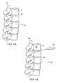
- FIG. 1Aillustrates a portion of a human spinal column
- FIG. 1Billustrates a portion of a human spinal column with an intervertebral disc removed
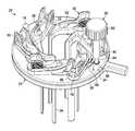
- FIG. 2illustrates a top perspective view of a retractor device according to one embodiment of the present disclosure
- FIG. 3illustrates a bottom perspective view of the retractor device of FIG. 2 ;
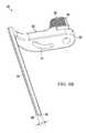
- FIG. 4Aillustrates a top perspective view of a blade of the retractor device of FIG. 2 according to one embodiment of the present disclosure
- FIG. 4Billustrates a bottom perspective view of the blade of FIG. 4A ;
- FIG. 5illustrates a top view of the retractor device of FIG. 2 with the blades in a closed position
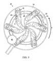
- FIG. 6illustrates a top view of the retractor device of FIG. 2 with the blades in an open position
- FIG. 7illustrates a bottom perspective view of the retractor device of FIG. 2 with blades in a closed position
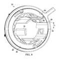
- FIG. 8illustrates a bottom perspective view of a retractor device according to another embodiment of the present disclosure
- FIG. 9Aillustrates a top perspective view of a retractor device with blades in a closed position according to another embodiment of the present disclosure
- FIG. 9Billustrates a side view of the retractor device of FIG. 9A ;
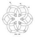
- FIG. 9Cillustrates a top view of the retractor device of FIG. 9A ;
- FIG. 10Aillustrates a top perspective view of the retractor device of FIG. 9A with the blades in a partially open position
- FIG. 10Billustrates a side view of the retractor device of FIG. 10A ;
- FIG. 10Cillustrates a top view of the retractor device of FIG. 10A ;
- FIG. 11Aillustrates a top perspective view of the retractor device of FIG. 9A with the blades in a substantially open position
- FIG. 11Billustrates a side view of the retractor device of FIG. 11A ;
- FIG. 11Cillustrates a top view of the retractor device of FIG. 11A ;
- FIG. 12illustrates a perspective view of a locking device for the retractor device of FIGS. 9-11 ;
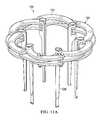
- FIG. 13Aillustrates a top perspective view of a retractor device with blades in a closed position according to yet another embodiment of the present disclosure
- FIG. 13Billustrates a top perspective view of the retractor device of FIG. 13A with blades in a partially open position
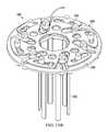
- FIG. 13Cillustrates a top perspective view of the retractor device of FIG. 13A with blades in a substantially open position
- FIG. 14illustrates a blade of the retractor device of FIG. 13A according to one embodiment of the present disclosure
- FIG. 15illustrates a top perspective view of the retractor device of FIG. 13A with a locking tool and rotation tool coupled thereto;
- FIG. 16illustrates a top perspective view of the retractor device of FIG. 13A with a locking tool and a translation tool coupled thereto.
- FIG. 1AA portion of a human spinal column 10 is schematically illustrated in FIG. 1A and includes a series of vertebrae 12 intersected by a series of intervertebral discs 14 .
- the vertebrae 12generally encapsulate a spinal cord 16 , which generally comprises nervous tissue and serves as the main pathway for information connecting the brain and peripheral nervous system.
- FIG. 1Bit sometimes becomes necessary to remove a diseased, or otherwise failing, intervertebral disc. Such procedures leave an intervertebral disc space 18 defined between adjacent vertebrae of the spinal column.
- Some surgical procedurescall for fusion of the adjacent vertebrae 12 , while other procedures may call for insertion of a prosthetic disc into the intervertebral disc space 18 .
- access to the intervertebral disc space 18 through tissueis required. According to the principles of the present disclosure, it is desirable to provide for minimally invasive access to the surgical site through such tissue.
- the retractor device 20is illustrated in FIGS. 2-8 .
- the retractor device 20is preferably used in surgical procedures involving the cervical and/or lumbar regions of the spinal column; however, the retractor device may be used in other surgical applications requiring distraction of tissue and such uses are contemplated as falling within the scope of the present disclosure.
- the retractor device 20includes a frame 22 , which includes a pair of concentric rings 24 , 26 , which are adapted to slide circumferentially relative to one another in a manner to be described.
- the frame 22includes an additional mounting ring 28 .
- the retractor device 20further includes a plurality of arm members 30 , which include a mounting portion 32 for coupling to the frame 22 and a blade portion 34 , which extends in a direction substantially perpendicular to a plane defined by the frame.
- the mounting portion 32is adapted for coupling to the frame 22 via an elongated slot 35 and an eccentric hole 36 defined through the mounting portion.
- the inner ring 26may include a peg-like element 38 disposed thereon for being received into the elongated slot 35 of the arm member 30 .
- the peg-like element 38may be substantially cylindrical in shape, however, other configurations are contemplated so long a the peg-like element fits within and is adapted for moving along the elongated slot 35 as will be described.
- the outer ring 24may include a plurality of mounting posts 40 for being received through the arm member 30 via the eccentric hole 36 .
- the mounting portion 32 of the arm member 30includes a spring-loaded latch member 42 as well as a pair of detents 44 to facilitate quick attachment and removal of the arm member 30 to the frame 22 .
- the mounting post 40may be stepped in diameter to include a larger head portion 46 relative to a shaft portion 48 ( FIG. 2 ).
- the spring loaded latch 42is adapted to bear against the shaft portion to retain the arm member 30 in engagement with the frame 22 .
- Such an arrangementfurther holds the arm member 30 in place in the vertical direction as the head portion 46 of the mounting post 40 will block removal of the arm member 30 .
- the detents 44may include a ribbed portion 50 to facilitate gripping of the arm member 30 during insertion and/or removal.
- the arms 30are movable from a substantially closed position ( FIG. 5 ) to a substantially open position ( FIG. 6 ).
- the retractor device 20may be inserted through a relatively small incision site and then later may be widened to allow access to the operation site.
- the retractor device 20includes an actuator 60 that, in some embodiments, has a knob 62 disposed at a distal end of a shaft 64 (as shown in FIG. 2 ).
- the actuator 60further includes a gear 66 for coupling to corresponding teeth 68 disposed along a circumference of the inner ring 26 .
- the gear 66may further engage corresponding teeth 69 disposed along a circumference of the mounting ring 28 as is illustrated in FIG. 8 .
- the shaft 64 of the actuator 60is stepped in diameter such that a lower portion adjacent to the gear 66 is smaller in diameter relative to a remaining portion of the shaft. This may accommodate size constraints associated with connection of the shaft 64 to the gear 66 , while also providing additional stability to the actuator 60 with the increased diameter portion of the shaft.
- a proximal end of the shaft 64may include a flange 70 for retaining the actuator 60 within the frame 22 .
- the actuator 60is rotated via rotation of the knob 62 .
- the teeth of gear 66thus engage the teeth 68 of the inner ring 26 to thereby urge the inner ring in a direction of rotation opposite that of the actuator gear 66 .
- Rotation of inner ring 26 in the direction Rcauses translation of the peg 38 along the elongated slot 35 to thereby move the blades from the closed position of FIG. 5 to the open position of FIG. 6 .
- rotationis only desired in one direction such that the surrounding tissue does not urge the blades 34 back to the closed position of FIG. 5 . Accordingly, with reference to FIG.
- the retractor device 20further includes a ratchet mechanism 72 , which may be a flexible limb integrally formed with the outer ring 24 that bears against the inner ring 26 and engages teeth 73 of the inner ring.
- a ratchet mechanism 72permits rotation in the desired direction of rotation R when opening the blades 34 , while preventing rotation in a direction opposite to R.
- a ratchet release member 74is connected to the ratchet mechanism 72 , which permits disengagement of the ratchet mechanism from the inner ring 26 to allow for collapse of the blades 34 to the closed position.
- the ratchet release member 74may be actuated in a radially outward direction to disengage the ratchet mechanism 72 .
- a gap 76may be defined in the outer ring 24 adjacent to the ratchet mechanism 72 .
- the arm members 30are removable from the frame 22 .
- a relatively small incision sitecan accommodate entry and extension of the blades 34 through tissue adjacent a surgical site.
- the blades 34take on a curved configuration, and thus have a width t 1 defined from a first terminal end 80 of the curved blade to a second terminal end 82 of the curved blade.
- the retractor device 20may be actuated to retract the tissue by actuating the knob 60 as described above.
- the arm members 30may be quickly removed and replaced with alternative arm members (relative to arm members having width t 1 ).
- arm members 30 with blades 34 having an increased widthmay replace the relatively thin blades of other embodiments.
- the blades 34 of FIG. 8may take on a curved configuration and have a width t 2 defined from a first terminal end 84 of the curved blade to a second terminal end 86 of the curved blade. The width t 2 is greater than the width t 1 . In this manner, the wider blades of FIG. 8 may be used to retain retraction without applying as much pressure to patient's tissue as would be applied by less thick blades.
- the arm members 30may be retracted by actuating the ratchet release member 72 .
- the arm members 30 having relatively thick bladese.g., FIG. 8
- Arm members 30 having relatively thin bladesmay be placed onto the frame 22 by inserting the mounting portion 32 over the mounting posts 40 via the eccentric holes 36 defined through the arm members. In this manner, the retractor device 20 may be removed from the body through a relatively small incision site, thus minimizing tissue damage.
- FIGS. 9-11illustrate an alternative retractor device 120 having a plurality of linkages 122 , which cooperate to define a frame 124 of the retractor device.
- a plurality of blades 126are coupled to the linkages 122 and extend in a direction substantially perpendicular to a plane defined by the frame 124 .
- the linkagescooperate to move the blades 126 from a first position to other positions.
- the bladesmay be moved from a substantially closed position (as shown in FIG. 9A ) to an intermediate position (as shown in FIG. 10A ), and to a substantially open position (as shown in FIG. 11A ) as will be described.
- the blades 126may be separate members, which are coupled to the linkages 122 via mechanical fasteners 128 , such as nuts.
- a proximal portion of the blademay have a cylindrical shape and be externally threaded.
- the proximal portion of the blade 126may pass through a hole defined at an intersection of three linkages 122 and be secured therethrough via the nut 128 .
- Such an arrangementfacilitates quick detachment of the blades 126 such that blades of a different size (i.e., length and/or width) may replace the blades initially disposed on the frame 124 .
- the blades 126may be integrally formed with the linkages 122 and thus not removable.
- the blades 126 of the embodiments depicted in FIGS. 9-11may be curved.
- the linkages 122are preferably similar in size and shape and take on a curved configuration.
- the linkages 122are interconnected to other linkages via mechanical fasteners 129 , such as rivets or screw/nut combinations, which are disposed through intermediate and outer holes 130 , 132 , respectively, defined through the linkages.
- mechanical fasteners 129such as rivets or screw/nut combinations
- each linkage 122may have three holes defined therethrough.
- the inner holes 128may accommodate corresponding blades 124 as described above, while sets of intermediate and outer holes 130 , 132 provide remaining points of interconnection for the linkages to complete the frame 124 of the retractor device 120 .
- the frame 124 of the retractor device 120includes three layers of linkages.
- a top layer L 1preferably includes six linkages 122 that are curved in the same direction and generally spiral about a longitudinal axis 140 defined through a center of the blades 126 when the frame is in the closed position ( FIG. 9A ).
- the linkages in layer L 1may take on a spiral shape when the frame 124 is in the closed position.
- An intermediate layer of linkages L 2includes six linkages 122 , which are disposed in the frame 124 such that they exhibit an opposite direction of curvature relative to the curvature of the linkages in layer L 1 .
- the linkages 122 in layer L 2thus generally spiral about the longitudinal axis 140 in a direction opposite that of the linkages in layer L 1 .
- a bottom layer L 3preferably includes six linkages 122 that are curved in the same direction and substantially in the same manner as the linkages of layer L 1 . That is, the linkages 122 in layer L 3 generally spiral about the longitudinal axis 140 and are longitudinally offset, yet aligned with the linkages in layer L 1 to permit interconnection of the layers.
- Each layer L 1 , L 2 and L 3preferably includes eighteen points of interconnection along each layer. Of course, other embodiments are contemplated with less or more points of interconnection and less or more layers.
- Each layer L 1 , L 2 and L 3 of linkagesis interconnected at the outer and intermediate holes 132 , 130 , respectively, via mechanical fasteners and is further interconnected at the inner holes via the blades 126 . In this manner, movement of one set of layered linkages (e.g., at one interconnection point defined at hole 132 ) will cause movement of the remainder of the frame 124 .
- the layered linkages 122 of the frame 124are interconnected in such a way that the frame is symmetrical when viewed in plan whether the frame is in a substantially closed position ( FIGS. 9A-C ), an intermediate position ( FIGS. 10A-C ), or a substantially open position ( FIGS. 11A-C ).
- This arrangementpermits the blades 126 to move in a simultaneous manner from a substantially closed position ( FIGS. 9A-C ) to a substantially open position ( FIGS. 11A-C ).
- a pair of handles 150 , 152may be coupled to one of the mechanical fasteners 129 disposed through one of the outer holes 132 .
- One of the handles 150may be fixedly coupled to the mechanical fastener 129 in between a linkage 122 of the top layer L 1 and a corresponding linkage 122 of the intermediate layer L 2 .
- the other handle 152may be further fixedly coupled to the same mechanical fastener 129 in between the linkage 122 of the intermediate layer L 2 and a corresponding linkage of the bottom layer L 3 .
- the handlesIn an initial position in which the frame 124 is substantially closed, the handles may initially extend away from one another.
- the handle 152When it is desired to actuate the frame 124 , the handle 152 may be manually moved towards the handle 150 to thereby cause the frame to open. More specifically, due to the fixed coupling of the handles 150 , 152 to the mechanical fastener 129 passing through the interconnection point, relative actuation of the handles towards one another will urge the corresponding linkages 122 in the top and bottom layers L 1 , L 3 , respectively, away from the corresponding linkage in the intermediate layer L 2 , thereby causing movement of the remainder of the frame 124 in a similar manner.
- the handles 150 , 152may be used with a locking device 154 equipped with a release mechanism for locking the retractor device 120 at a desired position.
- the locking device 154is a plier-style medical instrument that includes a ratchet mechanism 160 that facilitates opening of the frame 124 while disallowing movement of the blades in the opposite direction. That is, a series of teeth 162 of the ratchet mechanism 160 cooperate with the handle 152 as it is moved toward handle 150 to lock the blades into a desired position.
- FIG. 12is presented by way of example only as it is contemplated that other types of actuation and locking mechanisms may be used with the retractor device 120 .
- the retractor device 120may be used to facilitate access to a surgical site through tissue. After the incision is made, the retractor device 120 may be inserted through the incision site (blades 126 first) when the retractor device 120 is in a substantially closed position such as illustrated in FIGS. 9A-C . In a substantially closed position, the blades 126 are grouped together and depend from a center of the frame 124 . Once inserted, the retractor device 120 may be actuated to move the frame 124 , and therefore the blades 126 , from a closed position to a substantially open position such as illustrated in FIGS. 11A-C .
- Actuation of the retractor device 120causes the blades 126 to move in a simultaneous manner in an outward direction away from the center of the frame 124 , thus retracting the surrounding tissue and providing the surgeon access to the surgical site (e.g., diseased disc).
- the blades 126may be fully retracted to a substantially open position in which the blades are disposed adjacent a circumference of the frame 124 .
- other methodologiesmay call for less retraction, such as an intermediate retraction as illustrated in FIGS. 10A-C .
- FIGS. 13A-Cillustrate yet another embodiment of a retractor device 220 according to the principles of the present disclosure.
- the retractor device 220includes a frame 222 having an upper disc member 224 disposed over a lower disc member 226 .
- a plurality of arm members 228are coupled to the frame 222 .
- the arm members 228preferably include a mounting portion 230 and a blade portion 232 coupled with the mounting portion.
- the mounting portion 230 and blade portion 232may be integrally connected, thus comprising a single piece in which the mounting portion extends at a right angle to the blade portion.
- the mounting portion 230may further include a threaded post 234 disposed at a distal end of the mounting portion for engaging a mechanical fastener 236 , such as a correspondingly threaded nut.
- the lower disc member 226includes a plurality of channels 240 defined radially therethrough for receiving the mounting portions 230 of the arm members 228 .
- the nut 236is of sufficient diameter to retain the mounting portion 230 in the channel 240 .
- the lower disc member 226further includes a plurality of posts 242 for engaging the upper disc member 224 .
- the upper disc member 224includes a plurality of radially extending tabs 244 , which include elongated slots 246 defined therein. The elongated slots 246 are adapted to receive the posts 242 of the lower disc member 226 to thereby align and guide the upper disc member relative to the lower disc member.
- the tabs 244extend from a central portion 248 of the upper disc member 224 and increase in size in the radially outward direction to accommodate the elongated slot 246 defined therein, while also defining gaps 250 radially along the upper disc member 224 .
- the upper disc member 224further defines a plurality of holes 252 radially along the upper disc member.
- the retractor device 220permits either simultaneous or independent movement of the blades from a first, substantially closed position ( FIG. 13A ) to a second, substantially open position ( FIG. 13C ). In some situations, only partial opening of the blades 232 ( FIG. 13B ) may be desired. In methodologies where simultaneous actuation of the blades 232 is desired, the upper disc member 224 may be rotated in the direction R as indicated in FIG. 13A . To assist with such rotation, a rotation tool 260 may be used with the retractor device 220 as illustrated in FIG. 15 .
- the rotation tool 260includes a plurality of arms 262 having distal ends that couple with the upper disc member 224 .
- the arms 262may have pegs extending therefrom to engage the holes 252 defined radially along the upper disc member 224 .
- an actuator 264may be used to impart rotation to the tool, which in turn, imparts rotation to the upper disc member.
- the mounting portions 230 of the arm members 228are translated along the channel 240 and are guided between the radially extending tabs 244 via the gaps 250 defined therebetween.
- the posts 242 extending from the lower disc member 226maintain the upper disc member 224 in the desired alignment relative to the lower disc member during rotation. This is achieved by guiding movement of the upper disc member 224 via the posts 242 along the elongated slots 246 .
- the retractor device 220may be locked using a locking tool 270 as depicted in FIG. 15 .
- the locking tool 270may include a shaft 272 with a handle 274 disposed at a proximal end 276 of the locking tool.
- the locking tool 270further includes a socket 278 that mates with mechanical fastener 236 .
- the locking tool 270may be actuated to thereby rotate the socket 278 , which in turn, rotates the mechanical fastener 236 to thereby lock the retractor device.
- a translation tool 280may be used in cooperation with the retractor device 220 as depicted in FIG. 16 .
- the retractor device 220defines gaps between the mechanical fastener 236 and the radially extending tabs 244 of the upper disc member 224 .
- the translation tool 280may include a pair of arms 282 with sockets 284 disposed at the distal ends of the arms.
- One of the sockets 284may be coupled to one of the posts 242 of the lower disc member 226 , while the other socket 284 may be coupled to one of the mechanical fasteners 236 .
- the arm 282 corresponding to the engaged mechanical fastenermay be actuated to impart independent translational movement to the blade 232 associated with such mechanical fastener.
- the locking tool 270may then be used to lock the retractor device as described above with reference to FIG. 15 .
Landscapes
- Health & Medical Sciences (AREA)
- Life Sciences & Earth Sciences (AREA)
- Surgery (AREA)
- Heart & Thoracic Surgery (AREA)
- Engineering & Computer Science (AREA)
- Biomedical Technology (AREA)
- Nuclear Medicine, Radiotherapy & Molecular Imaging (AREA)
- Medical Informatics (AREA)
- Molecular Biology (AREA)
- Animal Behavior & Ethology (AREA)
- General Health & Medical Sciences (AREA)
- Public Health (AREA)
- Veterinary Medicine (AREA)
- Surgical Instruments (AREA)
Abstract
Description
Claims (23)
Priority Applications (3)
| Application Number | Priority Date | Filing Date | Title |
|---|---|---|---|
| US13/659,673US9693761B2 (en) | 2012-10-24 | 2012-10-24 | Retractor device and method |
| US14/030,546US9855027B2 (en) | 2012-10-24 | 2013-09-18 | Retractor device and method |
| PCT/US2013/066628WO2014066646A1 (en) | 2012-10-24 | 2013-10-24 | Retractor device and method |
Applications Claiming Priority (1)
| Application Number | Priority Date | Filing Date | Title |
|---|---|---|---|
| US13/659,673US9693761B2 (en) | 2012-10-24 | 2012-10-24 | Retractor device and method |
Related Child Applications (1)
| Application Number | Title | Priority Date | Filing Date |
|---|---|---|---|
| US14/030,546Continuation-In-PartUS9855027B2 (en) | 2012-10-24 | 2013-09-18 | Retractor device and method |
Publications (2)
| Publication Number | Publication Date |
|---|---|
| US20140114138A1 US20140114138A1 (en) | 2014-04-24 |
| US9693761B2true US9693761B2 (en) | 2017-07-04 |
Family
ID=50485935
Family Applications (1)
| Application Number | Title | Priority Date | Filing Date |
|---|---|---|---|
| US13/659,673ActiveUS9693761B2 (en) | 2012-10-24 | 2012-10-24 | Retractor device and method |
Country Status (2)
| Country | Link |
|---|---|
| US (1) | US9693761B2 (en) |
| WO (1) | WO2014066646A1 (en) |
Cited By (10)
| Publication number | Priority date | Publication date | Assignee | Title |
|---|---|---|---|---|
| US10687797B2 (en) | 2008-12-18 | 2020-06-23 | Howmedica Osteonics Corp. | Lateral access system for the lumbar spine |
| US11166709B2 (en) | 2016-08-23 | 2021-11-09 | Stryker European Operations Holdings Llc | Instrumentation and methods for the implantation of spinal implants |
| US11191532B2 (en) | 2018-03-30 | 2021-12-07 | Stryker European Operations Holdings Llc | Lateral access retractor and core insertion |
| US11413029B2 (en) | 2018-10-24 | 2022-08-16 | Stryker European Operations Holdings Llc | Anterior to psoas instrumentation |
| US20220257232A1 (en)* | 2019-11-05 | 2022-08-18 | John Selim SOLIMAN | Surgical retractor |
| US11564674B2 (en) | 2019-11-27 | 2023-01-31 | K2M, Inc. | Lateral access system and method of use |
| US11707294B2 (en) | 2018-02-15 | 2023-07-25 | Minnetronix Neuro, Inc. | Medical device for accessing the central nervous system |
| US11974775B2 (en) | 2020-01-22 | 2024-05-07 | Minnetronix Neuro, Inc. | Medical device for accessing the central nervous system |
| US12226088B2 (en) | 2016-03-09 | 2025-02-18 | Spinal Elements, Inc. | Retractor |
| US12232713B2 (en) | 2014-09-10 | 2025-02-25 | Spinal Elements, Inc. | Retractor |
Families Citing this family (27)
| Publication number | Priority date | Publication date | Assignee | Title |
|---|---|---|---|---|
| WO2006058221A2 (en) | 2004-11-24 | 2006-06-01 | Abdou Samy M | Devices and methods for inter-vertebral orthopedic device placement |
| US8764806B2 (en)* | 2009-12-07 | 2014-07-01 | Samy Abdou | Devices and methods for minimally invasive spinal stabilization and instrumentation |
| US8845728B1 (en) | 2011-09-23 | 2014-09-30 | Samy Abdou | Spinal fixation devices and methods of use |
| WO2013106347A1 (en) | 2012-01-10 | 2013-07-18 | The Board Of Trustees Of The Leland Stanford Junior University | Methods and devices for the prevention of surgical site infections |
| US20130226240A1 (en) | 2012-02-22 | 2013-08-29 | Samy Abdou | Spinous process fixation devices and methods of use |
| US9198767B2 (en) | 2012-08-28 | 2015-12-01 | Samy Abdou | Devices and methods for spinal stabilization and instrumentation |
| US9320617B2 (en) | 2012-10-22 | 2016-04-26 | Cogent Spine, LLC | Devices and methods for spinal stabilization and instrumentation |
| US8727975B1 (en) | 2013-05-10 | 2014-05-20 | Spine Wave, Inc. | Retractor for use in spinal surgery |
| WO2015138317A1 (en) | 2014-03-10 | 2015-09-17 | Stryker Corporation | Limb positioning system |
| AU2015292526A1 (en)* | 2014-07-23 | 2017-02-23 | Dilantha B. ELLEGALA | Modifications to access ports for minimally invasive neuro surgery |
| US9951904B2 (en) | 2015-03-24 | 2018-04-24 | Stryker Corporation | Rotatable seat clamps for rail clamp |
| US10857003B1 (en) | 2015-10-14 | 2020-12-08 | Samy Abdou | Devices and methods for vertebral stabilization |
| US9986989B2 (en)* | 2016-01-08 | 2018-06-05 | Boston Scientific Neuromodulation Corporation | Surgical retractor for implanting leads and methods of making and using |
| US10973648B1 (en) | 2016-10-25 | 2021-04-13 | Samy Abdou | Devices and methods for vertebral bone realignment |
| US10744000B1 (en) | 2016-10-25 | 2020-08-18 | Samy Abdou | Devices and methods for vertebral bone realignment |
| US10394347B2 (en)* | 2017-05-24 | 2019-08-27 | Dell Products L.P. | Curving mechanism for a portable mouse |
| WO2019094502A1 (en) | 2017-11-07 | 2019-05-16 | Prescient Surgical, Inc. | Methods and apparatus for prevention of surgical site infection |
| CN108378882B (en)* | 2018-04-09 | 2019-11-22 | 郑州大学第一附属医院 | A kind of tracheotomy dilation device |
| ES2968488T3 (en)* | 2018-09-18 | 2024-05-09 | Univ Brigham Young | External folding and deployable cutting or holding mechanism |
| EP3852642B1 (en)* | 2018-09-18 | 2024-04-03 | Brigham Young University | Developable and collapsable internal cutting mechanism |
| JP7333100B2 (en)* | 2018-09-18 | 2023-08-24 | ブリガム ヤング ユニバーシティ | Deployable and collapsible shaft deployment mechanism |
| US11179248B2 (en) | 2018-10-02 | 2021-11-23 | Samy Abdou | Devices and methods for spinal implantation |
| CN109316214B (en)* | 2018-10-11 | 2021-07-02 | 张树波 | Orthopedics knee joint mirror joint struts ware |
| CN109316213B (en)* | 2018-10-11 | 2021-07-23 | 青岛智兴医疗器械有限公司 | Orthopedics knee joint mirror joint struts ware |
| US20220126627A1 (en)* | 2019-02-15 | 2022-04-28 | Brigham Young University | Connected deployable arms off of cylindrical surfaces for increased mobility |
| US20240389992A1 (en)* | 2021-02-01 | 2024-11-28 | Clariance | Surgical Retractor |
| US11589858B2 (en)* | 2021-02-25 | 2023-02-28 | Bret Michael Berry | Surgical retractor |
Citations (75)
| Publication number | Priority date | Publication date | Assignee | Title |
|---|---|---|---|---|
| US1428653A (en) | 1920-06-10 | 1922-09-12 | Nick Peter | Dilator combination |
| US2083573A (en)* | 1936-04-18 | 1937-06-15 | Clifford V Morgan | Speculum |
| US2594086A (en) | 1950-04-29 | 1952-04-22 | David P Smith | Table supported abdominal retractor |
| US3965890A (en) | 1974-10-18 | 1976-06-29 | William Kohlmann Gauthier | Surgical retractor |
| US4130113A (en) | 1976-12-15 | 1978-12-19 | Richards Manufacturing Co., Inc. | Retractor |
| US4942700A (en) | 1988-10-27 | 1990-07-24 | Charles Hoberman | Reversibly expandable doubly-curved truss structure |
| US5081983A (en) | 1990-02-20 | 1992-01-21 | Villalta Josue J | Medical retractor device |
| US5125396A (en) | 1990-10-05 | 1992-06-30 | Ray R Charles | Surgical retractor |
| US5183032A (en)* | 1990-02-20 | 1993-02-02 | Villalta Josue J | Medical retractor device |
| US5377667A (en)* | 1992-12-03 | 1995-01-03 | Michael T. Patton | Speculum for dilating a body cavity |
| US5509893A (en)* | 1991-06-06 | 1996-04-23 | Meditech International Pty Ltd. | Speculum |
| US5657584A (en) | 1995-07-24 | 1997-08-19 | Rensselaer Polytechnic Institute | Concentric joint mechanism |
| US5846249A (en) | 1996-02-07 | 1998-12-08 | Pinotage, Llc | Video gynecological examination apparatus |
| US5944658A (en) | 1997-09-23 | 1999-08-31 | Koros; Tibor B. | Lumbar spinal fusion retractor and distractor system |
| US6096046A (en) | 1998-06-24 | 2000-08-01 | Weiss; Sol | Surgical instrument |
| US6206828B1 (en)* | 1999-06-08 | 2001-03-27 | John T. M. Wright | Sternal retractor with changeable blades and blade latch mechanism |
| US6280379B1 (en) | 1999-12-02 | 2001-08-28 | Scott Resnick | Speculum |
| US20010041828A1 (en) | 1997-05-02 | 2001-11-15 | Jens E. Hoekendijk | Surgical retractor |
| US6342036B1 (en) | 2001-02-02 | 2002-01-29 | Cheryl A. Cooper | Self-retaining vaginal retractor |
| US6354995B1 (en)* | 1998-04-24 | 2002-03-12 | Moshe Hoftman | Rotational lateral expander device |
| US20020072713A1 (en) | 2000-05-24 | 2002-06-13 | Surgical Innovations Ltd. | Surgical seal |
| US6440064B1 (en) | 1999-07-29 | 2002-08-27 | Max Hauser Süddeutsche Chirurgiemechanik GmbH | Apparatus for retracting tissue during surgical procedures |
| US20030088157A1 (en) | 2001-11-07 | 2003-05-08 | Vassiliades Thomas A. | Tissue spreader with force measurement, force indication or force limitation |
| US6613038B2 (en) | 1993-02-04 | 2003-09-02 | Bonutti 2003 Trust-A | Method of using expandable cannula |
| US20040087833A1 (en)* | 2002-10-30 | 2004-05-06 | Thomas Bauer | Retractor |
| US6746396B1 (en) | 1999-04-13 | 2004-06-08 | Viamedics, Llc | Self-seating surgical access device and method of use |
| US20040176665A1 (en) | 2002-06-26 | 2004-09-09 | Branch Charles L. | Instruments and methods for minimally invasive tissue retraction and surgery |
| US20050070765A1 (en) | 2003-09-18 | 2005-03-31 | Howmedica Osteonics Corp. | Surgical retractor with removable scissor arms |
| US20050080320A1 (en) | 2003-08-14 | 2005-04-14 | Lee Andrew Max | Multiple-blade retractor |
| US20050159651A1 (en) | 2003-12-18 | 2005-07-21 | Depuy Spine, Inc. | Surgical retractor systems and illuminated cannulae |
| US20050165281A1 (en)* | 2004-01-27 | 2005-07-28 | Sundaram Ravikumar | Surgical retractor apparatus for use with a surgical port |
| US20050203347A1 (en) | 2004-03-12 | 2005-09-15 | Guido Fehling | Anal retractor |
| US20050215866A1 (en) | 2004-03-25 | 2005-09-29 | Depuy Spine, Inc. | Surgical retractor positioning device |
| US20050277812A1 (en) | 2004-06-14 | 2005-12-15 | Myles Robert T | Minimally invasive surgical spinal exposure system |
| US20060052672A1 (en) | 2004-09-09 | 2006-03-09 | Landry Michael E | Surgical retraction apparatus method of use |
| US20060142643A1 (en) | 2004-12-23 | 2006-06-29 | Brad Parker | Radially expanding surgical retractor |
| US20060178566A1 (en) | 2005-02-07 | 2006-08-10 | Fetzer Peter E | Push-button activated grasper for surgical retractor |
| US20070010716A1 (en) | 2005-07-11 | 2007-01-11 | Malandain Hugues F | Surgical access device, system, and methods of use |
| US20070038033A1 (en) | 2005-04-25 | 2007-02-15 | Depuy Spine, Inc. | Cassette based surgical retractor |
| US20070156024A1 (en) | 2006-01-04 | 2007-07-05 | William Frasier | Surgical Retractors and Methods of Minimally Invasive Surgery |
| US20070156025A1 (en) | 2006-01-04 | 2007-07-05 | Connie Marchek | Surgical retractors and methods of minimally invasive surgery |
| US20070156026A1 (en) | 2006-01-04 | 2007-07-05 | William Frasier | Surgical access devices and methods of minimally invasive surgery |
| US20070203399A1 (en) | 2006-01-23 | 2007-08-30 | Gephart Matthew P | Retraction Apparatus and Method of Use |
| US20070238932A1 (en) | 2006-03-08 | 2007-10-11 | Jones Robert J | Surgical retractor and retractor assembly |
| US20070282171A1 (en) | 2006-06-06 | 2007-12-06 | Edward Karpowicz | Surgical Retractor System |
| US7344495B2 (en)* | 2004-01-27 | 2008-03-18 | Arvik Enterprises, Llc | Surgical retractor apparatus for use with a surgical port |
| US7374534B2 (en) | 2005-03-09 | 2008-05-20 | Dalton Brian E | Retractor and method for percutaneous tissue retraction and surgery |
| US20080183046A1 (en) | 2007-01-26 | 2008-07-31 | Wayne Boucher | Surgical retractor with removable blades and method of use |
| US20080319268A1 (en)* | 2005-12-15 | 2008-12-25 | David Michaeli | Radial Expansible Retractor For Minimally Invasive Surgery |
| US7537565B2 (en) | 2005-09-27 | 2009-05-26 | Daniel Bass | Surgical retractor with rotating blades |
| US20090158674A1 (en) | 2007-12-21 | 2009-06-25 | Schlumberger Technology Corporation | System and methods for actuating reversibly expandable structures |
| US7594888B2 (en) | 2004-10-29 | 2009-09-29 | Depuy Spine, Inc. | Expandable ports and methods for minimally invasive surgery |
| US20100069740A1 (en) | 2008-04-14 | 2010-03-18 | Blake Timothy Larson | Tissue-stabilization device and method for medical procedures |
| US20100081885A1 (en) | 2008-09-30 | 2010-04-01 | Aesculap Implant Systems, Inc. | Tissue retractor system |
| US20100160947A1 (en) | 2008-12-18 | 2010-06-24 | IMDS, Inc. | Systems and methods for dilation and dissection of tissues |
| US7780594B2 (en) | 2005-10-07 | 2010-08-24 | Alphatec Spine, Inc. | Retractor and methods of use |
| US20100274094A1 (en) | 2009-04-23 | 2010-10-28 | Custom Spine, Inc. | Tissue Retraction Apparatus |
| US7850608B2 (en) | 2002-10-25 | 2010-12-14 | K2M, Inc. | Minimal incision maximal access MIS spine instrumentation and method |
| US7892174B2 (en) | 2006-07-19 | 2011-02-22 | Zimmer Spine, Inc. | Surgical access system and method of using the same |
| US7931589B2 (en) | 2006-11-09 | 2011-04-26 | Ebi, Llc | Surgical retractor device and related methods |
| US20110224496A1 (en) | 2010-03-11 | 2011-09-15 | Mark Weiman | Tissue Retractor and Method of Use |
| US20110224497A1 (en) | 2010-03-11 | 2011-09-15 | Mark Weiman | Tissue Retractor and Methods Of Use |
| US20110237898A1 (en) | 2008-12-18 | 2011-09-29 | Medicinelodge, Inc. Dba Imds Co-Innovation | Lateral access system for the lumbar spine |
| US20110301423A1 (en) | 2007-10-22 | 2011-12-08 | Tibor Koros | Surgical retractor systems |
| US20110301421A1 (en)* | 2010-02-24 | 2011-12-08 | Meni-Med Ltd | Surgical retractor |
| US8075482B2 (en)* | 2007-02-22 | 2011-12-13 | Ethicon Endo-Surgery, Inc. | IRIS valve with control ring |
| US8083673B2 (en) | 2008-06-25 | 2011-12-27 | Howard Steven Rosen | Examination apparatus |
| US20120046527A1 (en) | 2010-03-11 | 2012-02-23 | Jason Cianfrani | Tissue Retractor and Method of Use |
| US8182519B2 (en) | 2009-08-05 | 2012-05-22 | Thomas Stuart Loftus | Method for performing minimally invasive surgury |
| US8192463B2 (en) | 2007-05-24 | 2012-06-05 | Mcloughlin Joseph | Surgical retractor and related methods |
| US20120172670A1 (en) | 2002-10-25 | 2012-07-05 | K2M, Inc. | Minimal incision maximal access mis spine instrumentation and method |
| US8262570B2 (en) | 2008-05-30 | 2012-09-11 | Pioneer Surgical Technology, Inc. | Retraction apparatus and method of use |
| US8267859B2 (en) | 2005-09-28 | 2012-09-18 | Holmed Corporation | Spreader insert for a retractor system |
| US20120245432A1 (en) | 2006-06-06 | 2012-09-27 | Edward Karpowicz | Surgical Retractor System |
| US20130066161A1 (en) | 2004-04-05 | 2013-03-14 | Covidien Lp | Surgical hand access apparatus |
- 2012
- 2012-10-24USUS13/659,673patent/US9693761B2/enactiveActive
- 2013
- 2013-10-24WOPCT/US2013/066628patent/WO2014066646A1/enactiveApplication Filing
Patent Citations (107)
| Publication number | Priority date | Publication date | Assignee | Title |
|---|---|---|---|---|
| US1428653A (en) | 1920-06-10 | 1922-09-12 | Nick Peter | Dilator combination |
| US2083573A (en)* | 1936-04-18 | 1937-06-15 | Clifford V Morgan | Speculum |
| US2594086A (en) | 1950-04-29 | 1952-04-22 | David P Smith | Table supported abdominal retractor |
| US3965890A (en) | 1974-10-18 | 1976-06-29 | William Kohlmann Gauthier | Surgical retractor |
| US4130113A (en) | 1976-12-15 | 1978-12-19 | Richards Manufacturing Co., Inc. | Retractor |
| US5024031A (en) | 1988-10-27 | 1991-06-18 | Charles Hoberman | Radial expansion/retraction truss structures |
| US4942700A (en) | 1988-10-27 | 1990-07-24 | Charles Hoberman | Reversibly expandable doubly-curved truss structure |
| US5081983A (en) | 1990-02-20 | 1992-01-21 | Villalta Josue J | Medical retractor device |
| US5183032A (en)* | 1990-02-20 | 1993-02-02 | Villalta Josue J | Medical retractor device |
| US5125396A (en) | 1990-10-05 | 1992-06-30 | Ray R Charles | Surgical retractor |
| US5509893A (en)* | 1991-06-06 | 1996-04-23 | Meditech International Pty Ltd. | Speculum |
| US5377667A (en)* | 1992-12-03 | 1995-01-03 | Michael T. Patton | Speculum for dilating a body cavity |
| US5505690A (en)* | 1992-12-03 | 1996-04-09 | Michael T. Patton | Speculum for dilating a body cavity |
| US6613038B2 (en) | 1993-02-04 | 2003-09-02 | Bonutti 2003 Trust-A | Method of using expandable cannula |
| US5657584A (en) | 1995-07-24 | 1997-08-19 | Rensselaer Polytechnic Institute | Concentric joint mechanism |
| US5846249A (en) | 1996-02-07 | 1998-12-08 | Pinotage, Llc | Video gynecological examination apparatus |
| US20010041828A1 (en) | 1997-05-02 | 2001-11-15 | Jens E. Hoekendijk | Surgical retractor |
| US6416468B2 (en) | 1997-05-02 | 2002-07-09 | Heartport, Inc. | Method of retracting a portion of a patient's body |
| US5944658A (en) | 1997-09-23 | 1999-08-31 | Koros; Tibor B. | Lumbar spinal fusion retractor and distractor system |
| US6354995B1 (en)* | 1998-04-24 | 2002-03-12 | Moshe Hoftman | Rotational lateral expander device |
| US6096046A (en) | 1998-06-24 | 2000-08-01 | Weiss; Sol | Surgical instrument |
| US6746396B1 (en) | 1999-04-13 | 2004-06-08 | Viamedics, Llc | Self-seating surgical access device and method of use |
| US6206828B1 (en)* | 1999-06-08 | 2001-03-27 | John T. M. Wright | Sternal retractor with changeable blades and blade latch mechanism |
| US6440064B1 (en) | 1999-07-29 | 2002-08-27 | Max Hauser Süddeutsche Chirurgiemechanik GmbH | Apparatus for retracting tissue during surgical procedures |
| US6280379B1 (en) | 1999-12-02 | 2001-08-28 | Scott Resnick | Speculum |
| US20020072713A1 (en) | 2000-05-24 | 2002-06-13 | Surgical Innovations Ltd. | Surgical seal |
| US7722570B2 (en) | 2000-05-24 | 2010-05-25 | Applied Medical Resources Corporation | Surgical seal |
| US6342036B1 (en) | 2001-02-02 | 2002-01-29 | Cheryl A. Cooper | Self-retaining vaginal retractor |
| US20030088157A1 (en) | 2001-11-07 | 2003-05-08 | Vassiliades Thomas A. | Tissue spreader with force measurement, force indication or force limitation |
| US20040176665A1 (en) | 2002-06-26 | 2004-09-09 | Branch Charles L. | Instruments and methods for minimally invasive tissue retraction and surgery |
| US8303499B2 (en) | 2002-10-25 | 2012-11-06 | K2M, Inc. | Minimal incision maximal access MIS spine instrumentation and method |
| US20120172670A1 (en) | 2002-10-25 | 2012-07-05 | K2M, Inc. | Minimal incision maximal access mis spine instrumentation and method |
| US7850608B2 (en) | 2002-10-25 | 2010-12-14 | K2M, Inc. | Minimal incision maximal access MIS spine instrumentation and method |
| US20040087833A1 (en)* | 2002-10-30 | 2004-05-06 | Thomas Bauer | Retractor |
| US20050080320A1 (en) | 2003-08-14 | 2005-04-14 | Lee Andrew Max | Multiple-blade retractor |
| US20050070765A1 (en) | 2003-09-18 | 2005-03-31 | Howmedica Osteonics Corp. | Surgical retractor with removable scissor arms |
| US20050159651A1 (en) | 2003-12-18 | 2005-07-21 | Depuy Spine, Inc. | Surgical retractor systems and illuminated cannulae |
| US20090018400A1 (en) | 2003-12-18 | 2009-01-15 | Depuy Spine, Inc. | Surgical retractor systems and illuminated cannulae |
| US7491168B2 (en)* | 2003-12-18 | 2009-02-17 | Depuy Spine, Inc. | Surgical retractor systems and illuminated cannulae |
| US8038611B2 (en) | 2003-12-18 | 2011-10-18 | Depuy Spine, Inc. | Surgical methods and surgical kits |
| US20110313256A1 (en) | 2003-12-18 | 2011-12-22 | Depuy Spine, Inc. | Surgical methods and surgical kits |
| US20050165281A1 (en)* | 2004-01-27 | 2005-07-28 | Sundaram Ravikumar | Surgical retractor apparatus for use with a surgical port |
| US7344495B2 (en)* | 2004-01-27 | 2008-03-18 | Arvik Enterprises, Llc | Surgical retractor apparatus for use with a surgical port |
| US7195592B2 (en)* | 2004-01-27 | 2007-03-27 | Sundaram Ravikumar | Surgical retractor apparatus for use with a surgical port |
| US7182730B2 (en)* | 2004-03-12 | 2007-02-27 | Fehling Ag | Anal retractor |
| US20050203347A1 (en) | 2004-03-12 | 2005-09-15 | Guido Fehling | Anal retractor |
| US20050215866A1 (en) | 2004-03-25 | 2005-09-29 | Depuy Spine, Inc. | Surgical retractor positioning device |
| US7435219B2 (en) | 2004-03-25 | 2008-10-14 | Depuy Spine, Inc. | Surgical retractor positioning device |
| US20090018401A1 (en) | 2004-03-25 | 2009-01-15 | Depuy Spine, Inc. | Surgical retractor positioning device |
| US20130066161A1 (en) | 2004-04-05 | 2013-03-14 | Covidien Lp | Surgical hand access apparatus |
| US20050277812A1 (en) | 2004-06-14 | 2005-12-15 | Myles Robert T | Minimally invasive surgical spinal exposure system |
| US20060052672A1 (en) | 2004-09-09 | 2006-03-09 | Landry Michael E | Surgical retraction apparatus method of use |
| US7556600B2 (en) | 2004-09-09 | 2009-07-07 | Zimmer Spine, Inc. | Surgical retraction apparatus and associated methods |
| US7594888B2 (en) | 2004-10-29 | 2009-09-29 | Depuy Spine, Inc. | Expandable ports and methods for minimally invasive surgery |
| US20060142643A1 (en) | 2004-12-23 | 2006-06-29 | Brad Parker | Radially expanding surgical retractor |
| US20060178566A1 (en) | 2005-02-07 | 2006-08-10 | Fetzer Peter E | Push-button activated grasper for surgical retractor |
| US20090124861A1 (en)* | 2005-02-07 | 2009-05-14 | Peter Edward Fetzer | Push-button activated grasper for surgical retractor |
| US7374534B2 (en) | 2005-03-09 | 2008-05-20 | Dalton Brian E | Retractor and method for percutaneous tissue retraction and surgery |
| US20070038033A1 (en) | 2005-04-25 | 2007-02-15 | Depuy Spine, Inc. | Cassette based surgical retractor |
| US20070010716A1 (en) | 2005-07-11 | 2007-01-11 | Malandain Hugues F | Surgical access device, system, and methods of use |
| US8105236B2 (en) | 2005-07-11 | 2012-01-31 | Kyphon Sarl | Surgical access device, system, and methods of use |
| US20120101341A1 (en) | 2005-07-11 | 2012-04-26 | Warsaw Orthopedic, Inc | Surgical access device system and methods of use |
| US7537565B2 (en) | 2005-09-27 | 2009-05-26 | Daniel Bass | Surgical retractor with rotating blades |
| US8267859B2 (en) | 2005-09-28 | 2012-09-18 | Holmed Corporation | Spreader insert for a retractor system |
| US7780594B2 (en) | 2005-10-07 | 2010-08-24 | Alphatec Spine, Inc. | Retractor and methods of use |
| US20080319268A1 (en)* | 2005-12-15 | 2008-12-25 | David Michaeli | Radial Expansible Retractor For Minimally Invasive Surgery |
| US8152721B2 (en)* | 2005-12-15 | 2012-04-10 | Microdel Idea Center Ltd. | Radial expansible retractor for minimally invasive surgery |
| US20110004067A1 (en)* | 2006-01-04 | 2011-01-06 | Connie Marchek | Surgical Retractors and Methods of Minimally Invasive Surgery |
| US20070156024A1 (en) | 2006-01-04 | 2007-07-05 | William Frasier | Surgical Retractors and Methods of Minimally Invasive Surgery |
| US20070156025A1 (en) | 2006-01-04 | 2007-07-05 | Connie Marchek | Surgical retractors and methods of minimally invasive surgery |
| US20070156026A1 (en) | 2006-01-04 | 2007-07-05 | William Frasier | Surgical access devices and methods of minimally invasive surgery |
| US20110245621A1 (en) | 2006-01-04 | 2011-10-06 | William Frasier | Surgical Access Devices and Methods of Minimally Invasive Surgery |
| US7758501B2 (en) | 2006-01-04 | 2010-07-20 | Depuy Spine, Inc. | Surgical reactors and methods of minimally invasive surgery |
| US7981031B2 (en) | 2006-01-04 | 2011-07-19 | Depuy Spine, Inc. | Surgical access devices and methods of minimally invasive surgery |
| US20090069635A1 (en) | 2006-01-23 | 2009-03-12 | Pioneer Surgical Technology, Inc. | Retraction Apparatus And Method Of Use |
| US20070203399A1 (en) | 2006-01-23 | 2007-08-30 | Gephart Matthew P | Retraction Apparatus and Method of Use |
| US7985179B2 (en) | 2006-01-23 | 2011-07-26 | Pioneer Surgical Technology | Retraction apparatus and method of use |
| US20070238932A1 (en) | 2006-03-08 | 2007-10-11 | Jones Robert J | Surgical retractor and retractor assembly |
| US20070282171A1 (en) | 2006-06-06 | 2007-12-06 | Edward Karpowicz | Surgical Retractor System |
| US20120245432A1 (en) | 2006-06-06 | 2012-09-27 | Edward Karpowicz | Surgical Retractor System |
| US7935053B2 (en) | 2006-06-06 | 2011-05-03 | Globus Medical, Inc | Surgical Retractor System |
| US7892174B2 (en) | 2006-07-19 | 2011-02-22 | Zimmer Spine, Inc. | Surgical access system and method of using the same |
| US7931589B2 (en) | 2006-11-09 | 2011-04-26 | Ebi, Llc | Surgical retractor device and related methods |
| US8062217B2 (en) | 2007-01-26 | 2011-11-22 | Theken Spine, Llc | Surgical retractor with removable blades and method of use |
| US20080183046A1 (en) | 2007-01-26 | 2008-07-31 | Wayne Boucher | Surgical retractor with removable blades and method of use |
| US8075482B2 (en)* | 2007-02-22 | 2011-12-13 | Ethicon Endo-Surgery, Inc. | IRIS valve with control ring |
| US8192463B2 (en) | 2007-05-24 | 2012-06-05 | Mcloughlin Joseph | Surgical retractor and related methods |
| US20110301423A1 (en) | 2007-10-22 | 2011-12-08 | Tibor Koros | Surgical retractor systems |
| US20090158674A1 (en) | 2007-12-21 | 2009-06-25 | Schlumberger Technology Corporation | System and methods for actuating reversibly expandable structures |
| US20100069740A1 (en) | 2008-04-14 | 2010-03-18 | Blake Timothy Larson | Tissue-stabilization device and method for medical procedures |
| US8262570B2 (en) | 2008-05-30 | 2012-09-11 | Pioneer Surgical Technology, Inc. | Retraction apparatus and method of use |
| US8083673B2 (en) | 2008-06-25 | 2011-12-27 | Howard Steven Rosen | Examination apparatus |
| US8211012B2 (en) | 2008-09-30 | 2012-07-03 | Aesculap Implant Systems, Llc | Tissue retractor system |
| US20100081885A1 (en) | 2008-09-30 | 2010-04-01 | Aesculap Implant Systems, Inc. | Tissue retractor system |
| US20110237898A1 (en) | 2008-12-18 | 2011-09-29 | Medicinelodge, Inc. Dba Imds Co-Innovation | Lateral access system for the lumbar spine |
| US20100160947A1 (en) | 2008-12-18 | 2010-06-24 | IMDS, Inc. | Systems and methods for dilation and dissection of tissues |
| US20100274094A1 (en) | 2009-04-23 | 2010-10-28 | Custom Spine, Inc. | Tissue Retraction Apparatus |
| US20120172669A1 (en) | 2009-08-05 | 2012-07-05 | Thomas Stuart Loftus | Retractor Component System And Method Comprising Same |
| US20120190935A1 (en) | 2009-08-05 | 2012-07-26 | Thomas Stuart Loftus | Retractor Component System And Method Comprising Same |
| US20120165613A1 (en) | 2009-08-05 | 2012-06-28 | Thomas Stuart Loftus | Retractor Component System And Method Comprising Same |
| US8182519B2 (en) | 2009-08-05 | 2012-05-22 | Thomas Stuart Loftus | Method for performing minimally invasive surgury |
| US8317692B2 (en) | 2009-08-05 | 2012-11-27 | Thomas Stuart Loftus | Blade body for use with a surgical retractor |
| US20110301421A1 (en)* | 2010-02-24 | 2011-12-08 | Meni-Med Ltd | Surgical retractor |
| US20110224496A1 (en) | 2010-03-11 | 2011-09-15 | Mark Weiman | Tissue Retractor and Method of Use |
| US20110224497A1 (en) | 2010-03-11 | 2011-09-15 | Mark Weiman | Tissue Retractor and Methods Of Use |
| US8353826B2 (en) | 2010-03-11 | 2013-01-15 | Globus Medical, Inc. | Tissue retractor and method of use |
| US20120046527A1 (en) | 2010-03-11 | 2012-02-23 | Jason Cianfrani | Tissue Retractor and Method of Use |
Non-Patent Citations (4)
| Title |
|---|
| Final Office Action, U.S. Appl. No. 14/030,546, dated Aug. 11, 2016, 18 pages. |
| International Search Report and Written Opinion, PCT/US2013/066628, dated Dec. 23, 2013, 10 pages. |
| International Search Report and Written Opinion, PCT/US2014/055681, dated Dec. 16, 2014, 8 pages. |
| U.S. Appl. No. 14/030,546, Non-Final Office Action, dated Jul. 22, 2014, 111 pages. |
Cited By (17)
| Publication number | Priority date | Publication date | Assignee | Title |
|---|---|---|---|---|
| US11925342B2 (en) | 2008-12-18 | 2024-03-12 | Howmedica Osteonics Corp. | Lateral access system for the lumbar spine |
| US10687797B2 (en) | 2008-12-18 | 2020-06-23 | Howmedica Osteonics Corp. | Lateral access system for the lumbar spine |
| US12232713B2 (en) | 2014-09-10 | 2025-02-25 | Spinal Elements, Inc. | Retractor |
| US12226087B2 (en) | 2016-03-09 | 2025-02-18 | Spinal Elements, Inc. | Retractor |
| US12226088B2 (en) | 2016-03-09 | 2025-02-18 | Spinal Elements, Inc. | Retractor |
| US11166709B2 (en) | 2016-08-23 | 2021-11-09 | Stryker European Operations Holdings Llc | Instrumentation and methods for the implantation of spinal implants |
| US12133643B2 (en) | 2016-08-23 | 2024-11-05 | Stryker European Operations Holdings Llc | Instrumentation and methods for the implantation of spinal implants |
| US12232765B2 (en) | 2018-02-15 | 2025-02-25 | Minnetronix Neuro, Inc. | Medical device for accessing the central nervous system |
| US11707294B2 (en) | 2018-02-15 | 2023-07-25 | Minnetronix Neuro, Inc. | Medical device for accessing the central nervous system |
| US11911016B2 (en) | 2018-03-30 | 2024-02-27 | Stryker European Operations Holdings Llc | Lateral access retractor and core insertion |
| US11191532B2 (en) | 2018-03-30 | 2021-12-07 | Stryker European Operations Holdings Llc | Lateral access retractor and core insertion |
| US11413029B2 (en) | 2018-10-24 | 2022-08-16 | Stryker European Operations Holdings Llc | Anterior to psoas instrumentation |
| US12256917B2 (en) | 2018-10-24 | 2025-03-25 | Stryker European Operations Holdings Llc | Anterior to psoas instrumentation |
| US11864739B2 (en)* | 2019-11-05 | 2024-01-09 | Matthew L. Bycer | Surgical retractor |
| US20220257232A1 (en)* | 2019-11-05 | 2022-08-18 | John Selim SOLIMAN | Surgical retractor |
| US11564674B2 (en) | 2019-11-27 | 2023-01-31 | K2M, Inc. | Lateral access system and method of use |
| US11974775B2 (en) | 2020-01-22 | 2024-05-07 | Minnetronix Neuro, Inc. | Medical device for accessing the central nervous system |
Also Published As
| Publication number | Publication date |
|---|---|
| US20140114138A1 (en) | 2014-04-24 |
| WO2014066646A1 (en) | 2014-05-01 |
Similar Documents
| Publication | Publication Date | Title |
|---|---|---|
| US9693761B2 (en) | Retractor device and method | |
| US9855027B2 (en) | Retractor device and method | |
| JP7218360B2 (en) | patient-worn surgical support | |
| US12226087B2 (en) | Retractor | |
| US12349945B2 (en) | Patient-mounted surgical support | |
| JP6998433B2 (en) | Minimal destructive retractor and related methods for spinal surgery | |
| JP7065597B2 (en) | Equipment and systems for surgical wounds | |
| JP6500013B2 (en) | Instrument for inserting an interspinous implant | |
| US12064100B2 (en) | Systems and methods for tissue retraction | |
| US20030220650A1 (en) | Minimally invasive bone manipulation device and method of use | |
| JP5710622B2 (en) | Distractor with removable stirrup base | |
| US20090093684A1 (en) | Surgical retractor device and method of use | |
| WO2016138081A1 (en) | Surgical retractor systems and methods | |
| JP2010504157A (en) | Retractor | |
| JP2014050714A (en) | Surgical device for minimally invasive spinal fusion and surgical system comprising the same | |
| US20220257232A1 (en) | Surgical retractor | |
| JP2016521626A (en) | Interspinous process implant with pin-driven engagement arm | |
| US20170311942A1 (en) | Spinal retractor with releasable arms | |
| ES2740639T3 (en) | Detachable actuator arm for distraction devices | |
| CN111526800A (en) | Patient Fixed Surgical Retractor | |
| WO2015041988A1 (en) | Retractor device and method |
Legal Events
| Date | Code | Title | Description |
|---|---|---|---|
| AS | Assignment | Owner name:BLACKSTONE MEDICAL, INC., TEXAS Free format text:ASSIGNMENT OF ASSIGNORS INTEREST;ASSIGNORS:FEDOROV, SERGEY;MOORE, JESSE;SEMLER, MARK EVALD;AND OTHERS;REEL/FRAME:029191/0634 Effective date:20121023 | |
| AS | Assignment | Owner name:JPMORGAN CHASE BANK, N.A., AS ADMINISTRATIVE AGENT Free format text:SECURITY INTEREST;ASSIGNOR:BLACKSTONE MEDICAL, INC.;REEL/FRAME:036682/0192 Effective date:20150831 | |
| STCF | Information on status: patent grant | Free format text:PATENTED CASE | |
| AS | Assignment | Owner name:JPMORGAN CHASE BANK, N.A., ILLINOIS Free format text:SECURITY INTEREST;ASSIGNOR:ORTHOFIX SPINAL IMPLANTS INC.;REEL/FRAME:050839/0856 Effective date:20191025 | |
| AS | Assignment | Owner name:ORTHOFIX SPINAL IMPLANTS INC., TEXAS Free format text:CHANGE OF NAME;ASSIGNOR:BLACKSTONE MEDICAL, INC.;REEL/FRAME:054458/0045 Effective date:20181221 | |
| MAFP | Maintenance fee payment | Free format text:PAYMENT OF MAINTENANCE FEE, 4TH YEAR, LARGE ENTITY (ORIGINAL EVENT CODE: M1551); ENTITY STATUS OF PATENT OWNER: LARGE ENTITY Year of fee payment:4 | |
| AS | Assignment | Owner name:ORTHOFIX HOLDINGS, INC., TEXAS Free format text:MERGER;ASSIGNOR:ORTHOFIX SPINAL IMPLANTS INC.;REEL/FRAME:055002/0751 Effective date:20201230 Owner name:ORTHOFIX INC., TEXAS Free format text:MERGER;ASSIGNOR:ORTHOFIX HOLDINGS, INC.;REEL/FRAME:055002/0841 Effective date:20201230 | |
| AS | Assignment | Owner name:JPMORGAN CHASE BANK, N.A., AS ADMINISTRATIVE ASSISTANT, ILLINOIS Free format text:SECURITY INTEREST;ASSIGNOR:ORTHOFIX US LLC;REEL/FRAME:056000/0153 Effective date:20210420 | |
| AS | Assignment | Owner name:ORTHOFIX US LLC, TEXAS Free format text:ENTITY CONVERSION;ASSIGNOR:ORTHOFIX INC.;REEL/FRAME:057247/0265 Effective date:20201231 | |
| AS | Assignment | Owner name:ORTHOFIX SPINAL IMPLANTS INC., TEXAS Free format text:RELEASE BY SECURED PARTY;ASSIGNOR:JPMORGAN CHASE BANK, N.A.;REEL/FRAME:065609/0247 Effective date:20231106 Owner name:ORTHOFIX US LLC, TEXAS Free format text:RELEASE BY SECURED PARTY;ASSIGNOR:JPMORGAN CHASE BANK, N.A.;REEL/FRAME:065609/0223 Effective date:20231106 | |
| AS | Assignment | Owner name:BLUE TORCH FINANCE LLC, AS COLLATERAL AGENT, NEW YORK Free format text:SECURITY INTEREST;ASSIGNOR:ORTHOFIX US LLC;REEL/FRAME:066256/0423 Effective date:20231106 | |
| AS | Assignment | Owner name:OXFORD FINANCE LLC, AS AGENT, VIRGINIA Free format text:SECURITY INTEREST;ASSIGNORS:ORTHOFIX MEDICAL INC.;ORTHOFIX US LLC;SPINAL KINETICS LLC;AND OTHERS;REEL/FRAME:069332/0761 Effective date:20241107 | |
| AS | Assignment | Owner name:THEKEN SPINE, LLC, CALIFORNIA Free format text:RELEASE BY SECURED PARTY;ASSIGNOR:BLUE TORCH FINANCE LLC;REEL/FRAME:069358/0110 Effective date:20241111 Owner name:SPINAL KINETICS LLC, CALIFORNIA Free format text:RELEASE BY SECURED PARTY;ASSIGNOR:BLUE TORCH FINANCE LLC;REEL/FRAME:069358/0110 Effective date:20241111 Owner name:SEASPINE ORTHOPEDICS CORPORATION, CALIFORNIA Free format text:RELEASE BY SECURED PARTY;ASSIGNOR:BLUE TORCH FINANCE LLC;REEL/FRAME:069358/0110 Effective date:20241111 Owner name:SEASPINE, INC., CALIFORNIA Free format text:RELEASE BY SECURED PARTY;ASSIGNOR:BLUE TORCH FINANCE LLC;REEL/FRAME:069358/0110 Effective date:20241111 Owner name:ORTHOFIX US, LLC, TEXAS Free format text:RELEASE BY SECURED PARTY;ASSIGNOR:BLUE TORCH FINANCE LLC;REEL/FRAME:069358/0110 Effective date:20241111 Owner name:ISOTIS ORTHOBIOLOGICS, INC., CALIFORNIA Free format text:RELEASE BY SECURED PARTY;ASSIGNOR:BLUE TORCH FINANCE LLC;REEL/FRAME:069358/0110 Effective date:20241111 | |
| MAFP | Maintenance fee payment | Free format text:PAYMENT OF MAINTENANCE FEE, 8TH YEAR, LARGE ENTITY (ORIGINAL EVENT CODE: M1552); ENTITY STATUS OF PATENT OWNER: LARGE ENTITY Year of fee payment:8 |