US9691303B2 - Electronic label having a timer function - Google Patents
Electronic label having a timer functionDownload PDFInfo
- Publication number
- US9691303B2 US9691303B2US14/853,563US201514853563AUS9691303B2US 9691303 B2US9691303 B2US 9691303B2US 201514853563 AUS201514853563 AUS 201514853563AUS 9691303 B2US9691303 B2US 9691303B2
- Authority
- US
- United States
- Prior art keywords
- electronic label
- substrate
- indicator
- switch
- processor
- Prior art date
- Legal status (The legal status is an assumption and is not a legal conclusion. Google has not performed a legal analysis and makes no representation as to the accuracy of the status listed.)
- Active
Links
Images


Classifications
- G—PHYSICS
- G09—EDUCATION; CRYPTOGRAPHY; DISPLAY; ADVERTISING; SEALS
- G09F—DISPLAYING; ADVERTISING; SIGNS; LABELS OR NAME-PLATES; SEALS
- G09F3/00—Labels, tag tickets, or similar identification or indication means; Seals; Postage or like stamps
- G09F3/08—Fastening or securing by means not forming part of the material of the label itself
- G09F3/18—Casings, frames or enclosures for labels
- G09F3/20—Casings, frames or enclosures for labels for adjustable, removable, or interchangeable labels
- G09F3/208—Electronic labels, Labels integrating electronic displays
- G—PHYSICS
- G06—COMPUTING OR CALCULATING; COUNTING
- G06K—GRAPHICAL DATA READING; PRESENTATION OF DATA; RECORD CARRIERS; HANDLING RECORD CARRIERS
- G06K19/00—Record carriers for use with machines and with at least a part designed to carry digital markings
- G06K19/06—Record carriers for use with machines and with at least a part designed to carry digital markings characterised by the kind of the digital marking, e.g. shape, nature, code
- G06K19/067—Record carriers with conductive marks, printed circuits or semiconductor circuit elements, e.g. credit or identity cards also with resonating or responding marks without active components
- G06K19/07—Record carriers with conductive marks, printed circuits or semiconductor circuit elements, e.g. credit or identity cards also with resonating or responding marks without active components with integrated circuit chips
- G06K19/077—Constructional details, e.g. mounting of circuits in the carrier
- G06K19/07749—Constructional details, e.g. mounting of circuits in the carrier the record carrier being capable of non-contact communication, e.g. constructional details of the antenna of a non-contact smart card
- G—PHYSICS
- G06—COMPUTING OR CALCULATING; COUNTING
- G06K—GRAPHICAL DATA READING; PRESENTATION OF DATA; RECORD CARRIERS; HANDLING RECORD CARRIERS
- G06K7/00—Methods or arrangements for sensing record carriers, e.g. for reading patterns
- G06K7/10—Methods or arrangements for sensing record carriers, e.g. for reading patterns by electromagnetic radiation, e.g. optical sensing; by corpuscular radiation
- G06K7/10009—Methods or arrangements for sensing record carriers, e.g. for reading patterns by electromagnetic radiation, e.g. optical sensing; by corpuscular radiation sensing by radiation using wavelengths larger than 0.1 mm, e.g. radio-waves or microwaves
- G06K7/10366—Methods or arrangements for sensing record carriers, e.g. for reading patterns by electromagnetic radiation, e.g. optical sensing; by corpuscular radiation sensing by radiation using wavelengths larger than 0.1 mm, e.g. radio-waves or microwaves the interrogation device being adapted for miscellaneous applications
- G—PHYSICS
- G09—EDUCATION; CRYPTOGRAPHY; DISPLAY; ADVERTISING; SEALS
- G09F—DISPLAYING; ADVERTISING; SIGNS; LABELS OR NAME-PLATES; SEALS
- G09F3/00—Labels, tag tickets, or similar identification or indication means; Seals; Postage or like stamps
- G09F3/02—Forms or constructions
- G09F3/0291—Labels or tickets undergoing a change under particular conditions, e.g. heat, radiation, passage of time
- G—PHYSICS
- G09—EDUCATION; CRYPTOGRAPHY; DISPLAY; ADVERTISING; SEALS
- G09F—DISPLAYING; ADVERTISING; SIGNS; LABELS OR NAME-PLATES; SEALS
- G09F3/00—Labels, tag tickets, or similar identification or indication means; Seals; Postage or like stamps
- G09F3/02—Forms or constructions
- G09F2003/0272—Labels for containers
- G—PHYSICS
- G09—EDUCATION; CRYPTOGRAPHY; DISPLAY; ADVERTISING; SEALS
- G09F—DISPLAYING; ADVERTISING; SIGNS; LABELS OR NAME-PLATES; SEALS
- G09F3/00—Labels, tag tickets, or similar identification or indication means; Seals; Postage or like stamps
- G09F3/08—Fastening or securing by means not forming part of the material of the label itself
- G09F3/10—Fastening or securing by means not forming part of the material of the label itself by an adhesive layer
Definitions
- the present subject matterrelates to an electronic label, and more particularly, to an electronic label having a timer function.
- Activitiesmay be undertaken at periodic intervals and/or for a predetermined duration, whether in accordance with a schedule or as desired.
- certain foodsfor example, eggs or rice are cooked for a designated amount of time to be optimal.
- teeth whiteners or hair dyesare applied for a predetermined amount of time to be effective, or may need to be applied periodically to maintain efficacy.
- Certain activities, for example, exercisemay be undertaken for a predetermined minimum amount of time to be effective.
- the efficacy of a medicationtypically depends on a patient adhering to the dosage and frequency requirements of the medication.
- Certain activities undertaken more often than recommendedmay produce unwanted effects. For example, undertaking certain exercises for prolonged periods or more often than recommended may lead to injuries. Certain medications, if consumed more often than prescribed, may produce serious complications and in some cases such complications may be more severe than the condition such medication is prescribed to treat.
- a physiciantypically advises an individual with information regarding how often a medication is to be consumed.
- information regarding how often to consume the medication and the dosage to consumemay be printed on a label that accompanies the medication.
- instructions associated with other products or activitiesmay include information about how often such product is to be consumed or activity is to be undertaken.
- the individualis still responsible for tracking when a dose of the medication has been consumed, a product has been utilized, and/or an activity has been undertaken. Further, the individual may need to track when to consume the next dose of the medication, or utilize the product and/or undertake the activity again. Such tracking may be particularly difficult if the memory of the patient is compromised, if the medication or product is not to be consumed or used, or the activity undertaken everyday or at regular intervals.
- an electronic labelincludes a first substrate, a second substrate, and an electronic circuit disposed between the first substrate and the second substrate.
- a switch, a processor, and an indicatorare coupled to the electronic circuit.
- the switchis adapted to be manually actuated, and in response to each of a plurality of actuations, the processor determines whether to actuate the indicator to indicate if at least a predetermined amount of time has elapsed.
- FIGS. 1A and 1Bare isometric views of an electronic label secured to a container
- FIG. 2is a plan view of the electronic label of FIG. 1 secured to a surface
- FIG. 3is a partially exploded sectional view taken along a line 3 - 3 of the electronic label of FIG. 2 ;
- FIG. 4Ais a block diagram of an electronic circuit of the electronic label of FIGS. 1 and 2 ;
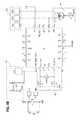
- FIG. 4Bis a combined block and schematic diagram of an electronic circuit of the electronic label of FIGS. 1 and 2 ;
- FIG. 5is a state diagram of operation of a processor of the electronic label of FIGS. 1 and 2 ;
- FIGS. 6 and 7are flowcharts of operations undertaken by the processor of the electronic label of FIGS. 1 and 2 ;
- FIG. 8is a plan view of a portion of the label of FIGS. 1 and 2 ;
- FIG. 9is a an exploded fragmentary cross-sectional view taken along a line 9 - 9 of FIG. 8 of the electronic label of FIGS. 1 and 2 ;
- FIG. 10is a plan view of an interior portion of the electronic label of FIGS. 1 and 2 .
- a container 100for example a container for a consumable product, has an electronic label 102 affixed thereto.
- a front face 104 of the electronic label 102may include one or more portions 106 in which information regarding the contents of the container 100 may be printed.
- the electronic label 102may include a first button or switch 108 , one or more indicator(s) 110 , and a second button or switch 112 .
- the electronic label 102is preferably made of flexible layers that are adhered or otherwise bonded together to form a flexible substantially flat member.
- the electronic label 102may include a releasable adhesive deposited on a rear face (not shown) thereof to secure the electronic label 102 to the container 100 .
- a releasable adhesivedeposited on a rear face (not shown) thereof to secure the electronic label 102 to the container 100 .
- such electronic label 102may be removed from the container 100 and affixed to another surface 114 .
- the usermay wish to remove the electronic label 102 from the container 100 and secure the electronic label 102 to a surface 114 convenient to the user such as, for example, a surface of a vanity mirror, a bulletin board, a cabinet, and/or the like.
- the releasable adhesive on the rear face of the electronic label 102may secure the label to the surface 114 , or another adhesive or securing apparatus available to the user may be used to secure the electronic label 102 to the surface 114 .
- the presence of the electronic label 102may serve as a reminder to the user to check whether a product associated with the electronic label 102 is to be consumed or used.
- another label(not shown) may be affixed to the container 100 that remains even after the electronic label 102 is removed.
- such additional labelmay identify the contents of the container, the quantity of such contents to be consumed, and the frequency such with which such product should be consumed.
- the electronic label 102may be provided without a container. For example, if the electronic label 102 is for use with an activity that does not require any additional product to undertake.
- the electronic label 102may incorporate a data port 120 that may be used to download into a memory ( FIG. 4A, 154 ) of the electronic label 102 , configuration information regarding when the product associated with the electronic label 102 is to be consumed.
- the electronic label 102may include a Radio Frequency Identification (RFID) circuit 122 that may be used to download such frequency information into the memory ( FIG. 4A, 154 ) of the electronic label 102 .
- RFIDRadio Frequency Identification
- Other ways of the downloading digital data into the memory ( FIG. 4A, 154 ) of the electronic label 102 apparent to those of ordinary skill in the artmay be used.
- the configuration information regarding the quantity and/or frequency with which the product associated with the electronic label 102 is to be consumedmay be downloaded into the electronic label 102 by a manufacturer of the electronic label 102 , a manufacturer of the product associated with the electronic label 102 , a seller or supplier of the product, and/or a seller or supplier of the electronic label 102 .
- the configuration informationmay include, for example, a minimum amount of time that should elapse between consumption of units of the product. Such time may be a constant such as 12 hours, 1 day, 3 days, and the like. Alternately, such time may vary and indicate that a second unit should be consumed after at least 12 hours have passed after a first unit is taken, and a third unit should be consumed at least 24 hours after the second does is taken, and so on. It should be apparent that the configuration information may include the minimum amount of time that should elapse between undertaking amounts of an activity.
- the configuration informationmay include the size of each unit of the product or the amount (e.g., time to spend) on the activity.
- the size of each unit to be consumedmay be represented as a quantity associated with each such unit (e.g., tablets, milliliters, and the like) of the product to be consumed. Such size may be identical each time the unit of the product is consumed, and the configuration information may indicate, for example, that each unit is one tablet. Alternately, the configuration information may indicate that the size of each unit varies and, for example, the first unit to consume is five tablets, the second unit is three tablets, and each of the remaining units is one tablet.
- the configuration informationmay also include the number of units of the product that are dispensed with the electronic label 102 .
- the configuration informationmay include a unit of an activity undertaken, and such unit may be represented, for example, as time spent on the activity or a number of repetitions of the activity to undertake.
- the seller of the productmay activate the electronic label 102 just prior to when the product and the electronic label 102 are provided to the user. Such activation may be undertaken by transmitting data that represents activation of the electronic label 102 via, for example, the data port 120 or the RFID circuit 122 . Alternately, such activation may be undertaken by pressing either one or both the first button 108 and the second button 112 in a predetermined sequence.
- such activationmay be undertaken by pressing the first button 108 in rapid succession a predetermined number of times, pressing the second button 112 in rapid succession a predetermined number of times, pressing the first button 108 and the second button 112 simultaneously, pressing and holding the first button 108 for a predetermined length of time, pressing and holding the second button 112 for a predetermined length of time, and the like.
- the usermay be instructed to activate the electronic label 102 as described above, before or just after consuming the first unit of a product or undertaking an activity a first time.
- the indicator(s) 110may include a light-emitting device, such as a light emitting diode (LED). If the user presses the first button 108 after the configuration information has been transmitted to the electronic label 102 , and the electronic label 102 has been activated, the light-emitting device may emit light only if it is time to take a unit of the product or undertake an amount of the activity as specified by the configuration information. In some cases, the light-emitting device may display a solid light for a predetermined amount of time in response to the user pressing the first button 108 if it is time to take a unit of the product, and alternatively may display a flashing light for a predetermined amount of time if it is not yet time to take such unit.
- a light-emitting devicesuch as a light emitting diode (LED).
- the indicator(s) 110may include a device that can display either numeric, alphabetic, and/or alphanumeric characters. Such device may include a seven-segment LED, a liquid crystal device, a plurality of individual LEDs, an organic light-emitting display (OLED), and/or the like.
- the indicator(s) 110may indicate how much time remains before the next unit of the product is to be taken, the product is to be used, an amount of an activity is to be undertaken.
- the indicator(s) 110may also indicate the number of units of the product that should be taken the next time.
- the indicator(s) 110may include an audio emitting device and/or a vibration device that is actuated when the product is to be used or taken, or an activity is to be performed.
- Such audio device and/or vibration devicemay be in addition to or instead of a light-emitting device.
- such audio emitting device or vibration devicemay be actuated for a predetermined amount of time when the user presses the first button 108 and if a unit of the product is to be taken, the product is to be used, or the activity performed.
- the indicator(s) 110 , the audio device, and/or the vibration devicemay be actuated periodically when the unit of the product is to be taken, the product used or the activity performed, without requiring the user to press the first button 108 .
- the second button 112may be actuated to record in the electronic label 102 that the product has been consumed or used, or activity performed.
- the electronic label 102may not include a second button 112 , and any other manner of indicating that the product has been consumed or activity undertaken may be employed.
- the first button 108may be pressed in succession or for a predetermined amount of time to indicate that the product has been consumed.
- the electronic label 102may be operated in the manner described above until all of the units of the product associated with the electronic label 102 have been consumed. Further, in some embodiments, when a further quantity of the product is provided to the user, for example, when product associated with the electronic label 102 is refilled, the electronic label 102 may be reused with such refill by resetting the electronic label 102 . Such reset may be accomplished, for example, by again undertaking activation the electronic label 102 as described above.
- the electronic label 102may include a first substrate 130 and a second substrate 132 , an electronic circuit 134 disposed between the first substrate 130 and the second substrate 132 , and an adhesive 136 that secures an inner face 138 of the first substrate 130 to an inner face 140 of the second substrate 132 .
- the first substrate 130 and the second substrate 132may comprise coated or uncoated paper, textiles, woven materials, plastic, films, gels, epoxies, fiberglass, and combinations thereof. Further, the substrates 130 , 132 that comprise the electronic label 102 may be manufactured from identical or different materials.
- the electronic circuit 134may include conductive traces deposited on the inner face 138 of the first substrate 130 , or the inner face 140 of the second substrate 132 .
- the electronic circuit 134may include a first conductive trace deposited on the inner face 138 of the first substrate 130 and a second conductive trace deposited on the inner face 140 of the second substrate 132 .
- such conductive traces, or a portion thereofmay be applied on the inner faces 138 , 140 using a printing process such as, for example, lithography, gravure, flexography, inkjet, foil transfer, and a combination thereof.
- the electronic circuit 134may be applied to a carrier separate from the first substrate 130 and the second substrate 132 that is deposited on and/or secured to the inner faces 138 , 140 .
- the electronic circuit 134also may include electronic components deposited and secured to the conductive traces thereof.
- Other ways of disposing the electronic circuit 134 between the first substrate 130 and the second substrate 132 apparent to those who have ordinary skill in the artmay be used.
- one embodiment of the electronic circuit 134may include a processor 150 , a data input-output circuit 152 , a memory 154 , a button circuit 156 , and an indicator circuit 158 .
- the processor 150 , the data input-output circuit 152 , and the memory 154are configured to transfer data therebetween.
- the data input-output circuit 152may receive data from an external device (not shown) and directly write data to the memory 154 , which may then be accessible the processor 150 .
- the processor 150may write data to the memory 154 that is thereafter accessible by an external reading device (not shown) via the data input-output circuit 152 .
- the button circuit 156may include the components necessary to implement the first button 108 and the second button 112 described above.
- the indicator circuit 158may include one or more visual, aural, and/or physical indicator(s) 110 including, for example, light emitters, sound emitters, and/or vibration generators, and driver electronics controlled by the processor 150 to actuate such indicator(s) 110 .
- the data input-output circuit 152includes one or more of a Serial-Peripheral Interface (SPI) interface or port, a Universal Serial Bus port, a radio frequency identification (RFID) transceiver, a radio transceiver that operated in accordance with Bluetooth or 802.11 wireless communications protocols, and the like.
- SPISerial-Peripheral Interface
- RFIDradio frequency identification
- the configuration informationmay be transmitted to the data input-output circuit 152 using an appropriate communication device (not shown).
- the data input-output circuit 152may directly store such configuration information in the memory 154 or provide such configuration information to the processor 150 , which stores the configuration information in the memory 154 .
- the processor 150initially operates in an inactive state 200 during which the processor 150 is in a low power state and undertakes only minimal activity. It should be apparent that the activity associated with the electronic label 102 may include consuming a unit of the product, using a unit of the product, or undertaking some other activity not associated with a product.
- the processor 150receives an indication that configuration data are available, the processor 150 transitions to a receive configuration data state 202 .
- the data input-output circuit 152generates a signal sensed by the processor 150 that indicates that configuration data are available when configuration data are transmitted thereto.
- the processor 150receives the configuration data, validates the configuration data, and stores the configuration data in the memory 154 .
- the processor 150may receive the configuration data and store such data in the memory 154 .
- the data input-output circuit 152may receive the configuration data, store the configuration data in the memory 154 , and then generate a signal to the processor 150 that the data are available, and the processor 150 transitions from the inactive state 200 to the receive configuration data state 202 in response to such signal.
- the processor 150may actuate one or more indicator(s) 110 to indicate whether valid configuration data were received and stored in the memory 154 .
- the processor 150determines that the data are not valid, the processor 150 returns to the inactive state 200 . Otherwise, the processor 150 transitions to an idle state 204 . Like the inactive state 200 , the idle state 204 is a low power state. If the button circuit 156 detects a button press, the processor 150 transitions to a determine operation state 206 .
- the processor 150determines whether the first button 108 , the second button 112 , or a combination thereof was pressed, and if such buttons 108 , 112 were pressed multiple times and or in a particular sequence within a predetermined duration. The processor 150 thus determines if the button press or sequence of button presses correspond to one of an activate command, a query command, a record activity command, and a reset command.
- the processor 150transitions to an activate electronic label state 208 .
- the processor 150sets a value of a variable activityCount to zero, sets a value of a variable labelActivated to true, sets up internal interrupts to respond to an interrupt (or tick) generated by the clock 160 , and transitions to the idle state 204 .
- the processor 150While in the determine operation state 206 , if the processor 150 determines that the button press or presses correspond to a record activity command, the processor 150 transitions to an update activity state 210 .
- the processor 150records the values of variables activityCount and tickCount in the memory 154 . If this is the first time the activity is being undertaken, then the values of these variables may be zero. Then, at block 213 , the processor 150 sets the value of the variable tickCount to zero, and increments the value of the variable activityCount by one. Thereafter, at block 214 , the processor 150 calculates the number of ticks that have to be received by the processor 150 from the clock 160 before a next time when the activity is to be undertaken.
- the processor 150sets a value of a variable nextActivity to the number of ticks calculated. Thereafter, the processor 150 transitions to the idle state 204 .
- the variables tickCount and nextActivitymay each include multiple counters. For example, one counter may count the number of ticks up to the number of ticks in 24 hours, and another counter may count the number of 24-hour periods.
- the storage of the variables tickCount and nextActivitymay be organized in other ways that may be apparent to those of skill in the art may be used so that these variables can accommodate the number of ticks that must elapse between activities undertaken.
- the processor 150determines that the button presses correspond to a query command, the processor 150 transitions to an actuate indicators state 218 .
- the processor 150determines, if the value of the variable labelActivated is true, at block 220 . If the value of such variable is not true, the processor 150 directs the indicator circuit 158 to actuate the indicator(s) 110 to indicate an error, at block 222 , and returns to the idle state 204 .
- the processor 150determines if the value of the variable activityCount is zero (i.e., no activity has been undertaken yet) or if the value of the variable tickCount is greater than or equal to the value of the variable nextActivity. If so, the processor 150 proceeds to block 226 , otherwise the processor 150 proceeds to block 228 .
- the processor 150directs the indicator circuit 158 to actuate the indicator(s) 110 to generate a predetermined indication that activity is due to be undertaken, and returns to the idle state 204 .
- the processor 150may direct the indicator circuit 158 to actuate the indicator(s) 110 in turn to generate a predetermined indication no activity is due or an indication of how long before the next time the activity is to be undertaken, and transitions to the idle state 204 . In other embodiments, the processor may not do anything at block 228 and just transition to the idle state 204 .
- the processor 150determines that the button press(es) correspond to a reset command, the processor 150 transitions to reset electronic label state 230 , sets the value of the labelActivated variable to false, and clears (or zeros) the values of one or more of the variables tickCount, activityCount, and nextActivity.
- the processor 150may clear the configuration data stored and/or the history stored in the memory 154 . Further, the processor 150 may configure itself to ignore interrupts from the clock 160 or configure the clock 160 not to generate such interrupts. Thereafter, the processor 150 transitions to the inactive state 200 . After such reset of the electronic label 102 , the electronic label 102 may be reused, for example, with a refill of the product associated with the electronic label or with a different activity.
- the processor 150transitions to an update time state 232 .
- the processor 150increments the value of the variable tickCount by one.
- the processor 150may determine if the value of the variable tickCount is greater than the value of the variable nextActivity, and if so, the processor 150 may direct the indicator circuit 158 to actuate the indicator(s) 110 to generate an indication that the activity is due. Thereafter, the processor 150 returns to the idle state 204 .
- Instructions executed by the processor 150 to undertake the actions during the states described abovemay be stored in a non-transient memory internal to the processor 150 or in a predetermined segment of the memory 154 reserved for program instructions. Such memory may also include default or predetermined configuration information that may be used if additional or different configuration information is not supplied to the electronic label 102 .
- the electronic label 102may comprise a programmable element, discrete components, firmware, or a combination thereof and the functions undertaken by the processor 150 may be implemented by programming and/or by hardware and/or firmware as desired.
- the processor 150and memory in which to store instructions executed by such processor 150 to operate the electronic label 102 , may be provided by an individual component such as an application-specific integrated circuit (ASIC), a field-programmable gate array (FPGA), a discrete logic device, a state machine, and the like.
- ASICapplication-specific integrated circuit
- FPGAfield-programmable gate array
- the memory 154may be queried by a reading device that communicates using the data input-output circuit 152 , such as, for example, an RFID reader or a programming device. Because the processor 150 at block 212 , FIG. 6 , records the values of the variables activityCount and tickCount in the memory 154 each time an activity is undertaken, such recorded information may be retrieved from the memory 154 to determine how regularly the user undertook the activity associated with the electronic label 102 .
- a physicianmay use such a history of such activity (i.e., dose consumption) that shows the elapsed time between doses to assess the effectiveness of a medication, or how well the user has followed a treatment plan.
- the first substrate 130may include an orifice 300 through which light emitted by an LED 302 passes.
- the LED 302may be coupled to the electronic circuit 134 deposited on the second substrate 132 of the electronic label 102 .
- a carrier or channel 304may be formed into which the LED 302 may be disposed.
- the carrier 304directs light emitted by the LED 302 outwardly through the orifice 300 .
- the light emitted by the LED 302may scatter within the carrier and appear as a spot of light larger the LED.
- the carrier 304may be formed from one of a polymer, a resin, a plastic, and the like.
- the carrier 304may be formed in situ on the second substrate 132 , for example, by inkjet printing, lithography, flexography, and/or gravure printing such material.
- Such channelsmay also be formed by depositing a plastic material (e.g., ABS), in a 3-dimensional deposition or lamination process.
- the carrier 304may be formed separately and adhered to the second substrate 132 .
- the carrier 304may have one or more orifices or vias 306 through which the pins of the LED 302 may contact the conductive traces of the electronic circuit 134 .
- the carrier 304may be formed as a shape that is lit by one or more LEDs 302 .
- the carrier 304is a material in which light scatters, then when the LEDs 302 are actuated, the light emitted by such LEDs 302 scatters throughout the carrier 304 and causes the shape represented by the carrier 304 to be apparent through the first substrate 130 .
- the carrier 304may have one or more orifices or vias 306 therethrough, and the LEDs 302 may be disposed on the carrier 304 such that the pins of the LEDs 302 pass through such vias and contact conductive traces of the electronic circuit 134 .
- carrier 304 for diffusing lightmay be used in other electronic label applications or products, not only electronic label associated with dispensed medicines.
- such productsmay include greeting cards, books, advertising or information labels, and the like.
- the electronic label 102may be configured to operate as a timer. In one embodiment, the electronic label 102 may be configured to actuate one or more indicators 110 after a predetermined amount of time has elapsed after pressing a predetermined combination of buttons or switches 108 , 112 . In another embodiment, each press of, for example, the first button 108 may increment an amount of time that must elapse before the indicators 110 are actuated. For example, each press may add one minute to such amount of time. Then, pressing the second button 112 may start the timer. Thereafter, one or more of the indicators 110 may be actuated after the amount of time configured using the first button 108 elapses. The timing capabilities of the electronic 102 may be used for other applications apparent to those who have skill in the art.
- the electronic label 102 described abovemay be used for any application in which activities need to be undertaken at predetermined intervals or on a particular schedule. Further, as noted above, some features of the electronic label 102 , for example, such as the carrier to direct illumination by a light source, may have applications in products other than electronic labels.
Landscapes
- Engineering & Computer Science (AREA)
- Physics & Mathematics (AREA)
- General Physics & Mathematics (AREA)
- Theoretical Computer Science (AREA)
- Health & Medical Sciences (AREA)
- Toxicology (AREA)
- Electromagnetism (AREA)
- General Health & Medical Sciences (AREA)
- Artificial Intelligence (AREA)
- Computer Vision & Pattern Recognition (AREA)
- Computer Hardware Design (AREA)
- Microelectronics & Electronic Packaging (AREA)
- Infusion, Injection, And Reservoir Apparatuses (AREA)
Abstract
Description
Claims (20)
Priority Applications (2)
| Application Number | Priority Date | Filing Date | Title |
|---|---|---|---|
| US14/853,563US9691303B2 (en) | 2015-09-14 | 2015-09-14 | Electronic label having a timer function |
| PCT/US2016/051270WO2017048624A1 (en) | 2015-09-14 | 2016-09-12 | Electronic label having a timer function |
Applications Claiming Priority (1)
| Application Number | Priority Date | Filing Date | Title |
|---|---|---|---|
| US14/853,563US9691303B2 (en) | 2015-09-14 | 2015-09-14 | Electronic label having a timer function |
Publications (2)
| Publication Number | Publication Date |
|---|---|
| US20170076642A1 US20170076642A1 (en) | 2017-03-16 |
| US9691303B2true US9691303B2 (en) | 2017-06-27 |
Family
ID=57121491
Family Applications (1)
| Application Number | Title | Priority Date | Filing Date |
|---|---|---|---|
| US14/853,563ActiveUS9691303B2 (en) | 2015-09-14 | 2015-09-14 | Electronic label having a timer function |
Country Status (2)
| Country | Link |
|---|---|
| US (1) | US9691303B2 (en) |
| WO (1) | WO2017048624A1 (en) |
Families Citing this family (9)
| Publication number | Priority date | Publication date | Assignee | Title |
|---|---|---|---|---|
| WO2016025755A1 (en) | 2014-08-13 | 2016-02-18 | R.R. Donnelley & Sons Company | Method and apparatus for producing an electronic device |
| EP3183693B1 (en) | 2014-08-19 | 2018-08-29 | R. R. Donnelley & Sons Company | Apparatus and method for monitoring a package during transit |
| WO2017120226A1 (en) | 2016-01-04 | 2017-07-13 | R.R. Donnelley & Sons Company | Multiple detector apparatus and method for monitoring an environment |
| US10342136B2 (en) | 2016-09-23 | 2019-07-02 | R.R. Donnelley & Sons Company | Monitoring device |
| US10445692B2 (en) | 2017-03-06 | 2019-10-15 | Cryovac, Llc | Monitoring device and method of operating a monitoring device to transmit data |
| US11240916B2 (en) | 2017-05-31 | 2022-02-01 | Cryovac, Llc | Electronic device, method and apparatus for producing an electronic device, and composition therefor |
| WO2019213712A1 (en)* | 2018-05-10 | 2019-11-14 | Senver Holdings Pty Ltd | Label and timing device |
| US11074488B2 (en)* | 2018-07-09 | 2021-07-27 | Tomas Francis Klimt | Wearable device with electronically-readable tag |
| CN109036102B (en)* | 2018-08-06 | 2021-07-20 | 河南大学 | Photovoltaic timing labels for medical reagents and food |
Citations (39)
| Publication number | Priority date | Publication date | Assignee | Title |
|---|---|---|---|---|
| US6019865A (en) | 1998-01-21 | 2000-02-01 | Moore U.S.A. Inc. | Method of forming labels containing transponders |
| US6043745A (en) | 1997-11-13 | 2000-03-28 | Micron Technology, Inc. | Electronic devices and methods of forming electronic devices |
| WO2000073082A1 (en) | 1999-06-01 | 2000-12-07 | 3M Innovative Properties Company | Random microembossed receptor media |
| US6420096B1 (en) | 1999-04-03 | 2002-07-16 | Koninklijke Philips Electronics N.V. | Method of manufacturing electronic stripline components |
| US6421013B1 (en) | 1999-10-04 | 2002-07-16 | Amerasia International Technology, Inc. | Tamper-resistant wireless article including an antenna |
| WO2003006736A1 (en) | 2001-07-13 | 2003-01-23 | Foto-Wear, Inc. | Sublimation dye thermal transfer paper and transfer method |
| JP2003277653A (en) | 2002-03-20 | 2003-10-02 | Seiko Epson Corp | Aqueous ink composition set and recording method |
| US20040066296A1 (en) | 2001-11-15 | 2004-04-08 | Atherton Peter S. | Tamper indicating radio frequency identification label with tracking capability |
| US6886745B2 (en)* | 1999-12-15 | 2005-05-03 | Store Electronic Systems Technologies | Electronic label system for displaying prices in a sale outlet |
| US6888509B2 (en) | 2000-03-21 | 2005-05-03 | Mikoh Corporation | Tamper indicating radio frequency identification label |
| US6924781B1 (en)* | 1998-09-11 | 2005-08-02 | Visible Tech-Knowledgy, Inc. | Smart electronic label employing electronic ink |
| US7042357B2 (en) | 2003-03-26 | 2006-05-09 | Proximities, Inc. | Non-reusable identification device |
| US7057495B2 (en)* | 2002-10-17 | 2006-06-06 | Paksense, Llc | Perishable product electronic label including time and temperature measurement |
| US7168626B2 (en) | 2004-10-08 | 2007-01-30 | Proximities, Inc. | Identification band using shorting wire for enabling/disabling an RFID transponder contained thereon |
| US7174277B2 (en)* | 2000-12-15 | 2007-02-06 | Phatrat Technology Llc | Product integrity systems and associated methods |
| US7204425B2 (en) | 2002-03-18 | 2007-04-17 | Precision Dynamics Corporation | Enhanced identification appliance |
| US7295115B2 (en) | 2002-10-18 | 2007-11-13 | Aeroscout, Ltd. | Radio-frequency identification (RFID) tag employing unique reception window and method therefor |
| US7316358B2 (en) | 2002-03-18 | 2008-01-08 | Precision Dynamics Corporation | Identification band with adhesively attached coupling elements |
| US7377447B2 (en) | 2005-12-05 | 2008-05-27 | Rcd Technology, Inc. | Tuned radio frequency identification (RFID) circuit used as a security device for wristbands and package security |
| US7417541B2 (en) | 2004-10-08 | 2008-08-26 | Bartronics America, Inc. | Identification band with regions having electro-magnetically detectable regions |
| US7586412B2 (en) | 2005-04-25 | 2009-09-08 | Nec Corporation | Wireless tag, wireless tag reader/writer, wireless tag information provision method, and wireless tag system |
| US7639135B2 (en) | 2004-10-28 | 2009-12-29 | Microstrain, Inc. | Identifying substantially related objects in a wireless sensor network |
| US7737839B1 (en) | 2008-01-24 | 2010-06-15 | Sprint Communications Company L.P. | System and method for protecting pocket-portable electronic devices |
| US7856339B2 (en) | 2000-12-15 | 2010-12-21 | Phatrat Technology, Llc | Product integrity tracking shipping label, system and associated method |
| US20110131854A1 (en) | 2009-12-09 | 2011-06-09 | Wristband Resources, Inc. | Sheet of wristbands |
| US8203446B2 (en) | 2008-09-30 | 2012-06-19 | Fujifilm Corporation | Radio communication terminal |
| US8219466B2 (en) | 2002-08-05 | 2012-07-10 | John Yupeng Gui | System and method for providing asset management and tracking capabilities |
| US8317084B2 (en)* | 2009-09-17 | 2012-11-27 | Nokia Corporation | Package content control |
| US8354927B2 (en) | 2002-06-11 | 2013-01-15 | Intelligent Technologies International, Inc. | Shipping container monitoring based on door status |
| US8590799B2 (en) | 2010-04-30 | 2013-11-26 | Jun Liu | Systems, methods, apparatus of a secure RFID record |
| US8618914B2 (en) | 2010-01-05 | 2013-12-31 | The Regents Of The University Of California | MEMS sensor enabled RFID system and method for operating the same |
| US8640259B2 (en)* | 2005-01-20 | 2014-01-28 | The Invention Science Fund I, Llc | Notarizable electronic paper |
| WO2014067578A1 (en) | 2012-10-31 | 2014-05-08 | Hewlett-Packard Indigo B.V. | Method and apparatus for forming on a substrate a pattern of a material |
| US8762212B2 (en)* | 1995-07-31 | 2014-06-24 | Information Planning & Management Service, Inc. | Electronic product information display system |
| US9030724B2 (en)* | 2008-07-03 | 2015-05-12 | Chromera, Inc. | Flexible and printable electrooptic devices |
| US9077183B2 (en) | 2011-09-06 | 2015-07-07 | Portland State University | Distributed low-power wireless monitoring |
| US9087318B1 (en)* | 2013-11-08 | 2015-07-21 | Sprint Communications Company L.P. | Visually readable electronic label |
| US20160050762A1 (en) | 2014-08-13 | 2016-02-18 | R.R. Donnelley & Sons Company | Method and apparatus for producing an electronic device |
| US20160055453A1 (en) | 2014-08-19 | 2016-02-25 | R.R. Donnelley & Sons Company | Apparatus and method for monitoring a package during transit |
Family Cites Families (4)
| Publication number | Priority date | Publication date | Assignee | Title |
|---|---|---|---|---|
| US5802015A (en)* | 1997-05-05 | 1998-09-01 | Rothschild Technology, L.L.C. | Intelligent label |
| US7993055B2 (en)* | 2008-03-28 | 2011-08-09 | Lloyd Cleveland Nurse | Method and apparatus for alerting a person at medicine dosing times |
| US8870083B2 (en)* | 2012-02-27 | 2014-10-28 | L&P Property Management Company | Mattress age indicator |
| FR2997218B1 (en)* | 2012-10-23 | 2014-11-21 | Jackel Internat Europ | MULTILAYER LIGHT LABEL AND BOTTLE EQUIPPED WITH AT LEAST ONE LIGHT LABEL AS PRECEDED |
- 2015
- 2015-09-14USUS14/853,563patent/US9691303B2/enactiveActive
- 2016
- 2016-09-12WOPCT/US2016/051270patent/WO2017048624A1/ennot_activeCeased
Patent Citations (44)
| Publication number | Priority date | Publication date | Assignee | Title |
|---|---|---|---|---|
| US8762212B2 (en)* | 1995-07-31 | 2014-06-24 | Information Planning & Management Service, Inc. | Electronic product information display system |
| US6043745A (en) | 1997-11-13 | 2000-03-28 | Micron Technology, Inc. | Electronic devices and methods of forming electronic devices |
| US6019865A (en) | 1998-01-21 | 2000-02-01 | Moore U.S.A. Inc. | Method of forming labels containing transponders |
| US6924781B1 (en)* | 1998-09-11 | 2005-08-02 | Visible Tech-Knowledgy, Inc. | Smart electronic label employing electronic ink |
| US6420096B1 (en) | 1999-04-03 | 2002-07-16 | Koninklijke Philips Electronics N.V. | Method of manufacturing electronic stripline components |
| WO2000073082A1 (en) | 1999-06-01 | 2000-12-07 | 3M Innovative Properties Company | Random microembossed receptor media |
| US6421013B1 (en) | 1999-10-04 | 2002-07-16 | Amerasia International Technology, Inc. | Tamper-resistant wireless article including an antenna |
| US6886745B2 (en)* | 1999-12-15 | 2005-05-03 | Store Electronic Systems Technologies | Electronic label system for displaying prices in a sale outlet |
| US6888509B2 (en) | 2000-03-21 | 2005-05-03 | Mikoh Corporation | Tamper indicating radio frequency identification label |
| US8428904B2 (en) | 2000-12-15 | 2013-04-23 | Tvipr, Llc | Product integrity tracking system, shipping label, and associated method |
| US8280682B2 (en) | 2000-12-15 | 2012-10-02 | Tvipr, Llc | Device for monitoring movement of shipped goods |
| US7856339B2 (en) | 2000-12-15 | 2010-12-21 | Phatrat Technology, Llc | Product integrity tracking shipping label, system and associated method |
| US7174277B2 (en)* | 2000-12-15 | 2007-02-06 | Phatrat Technology Llc | Product integrity systems and associated methods |
| US7627451B2 (en) | 2000-12-15 | 2009-12-01 | Apple Inc. | Movement and event systems and associated methods |
| US8126675B2 (en) | 2000-12-15 | 2012-02-28 | Phatrat Technology, Llc | Product integrity tracking shipping label, and associated method |
| WO2003006736A1 (en) | 2001-07-13 | 2003-01-23 | Foto-Wear, Inc. | Sublimation dye thermal transfer paper and transfer method |
| US20040066296A1 (en) | 2001-11-15 | 2004-04-08 | Atherton Peter S. | Tamper indicating radio frequency identification label with tracking capability |
| US7204425B2 (en) | 2002-03-18 | 2007-04-17 | Precision Dynamics Corporation | Enhanced identification appliance |
| US7316358B2 (en) | 2002-03-18 | 2008-01-08 | Precision Dynamics Corporation | Identification band with adhesively attached coupling elements |
| JP2003277653A (en) | 2002-03-20 | 2003-10-02 | Seiko Epson Corp | Aqueous ink composition set and recording method |
| US8354927B2 (en) | 2002-06-11 | 2013-01-15 | Intelligent Technologies International, Inc. | Shipping container monitoring based on door status |
| US8219466B2 (en) | 2002-08-05 | 2012-07-10 | John Yupeng Gui | System and method for providing asset management and tracking capabilities |
| US7057495B2 (en)* | 2002-10-17 | 2006-06-06 | Paksense, Llc | Perishable product electronic label including time and temperature measurement |
| US7295115B2 (en) | 2002-10-18 | 2007-11-13 | Aeroscout, Ltd. | Radio-frequency identification (RFID) tag employing unique reception window and method therefor |
| US7283054B2 (en) | 2003-03-26 | 2007-10-16 | Proximities, Inc. | Tamper-resistant RFID disabling apparatus and method of manufacturing |
| US7042357B2 (en) | 2003-03-26 | 2006-05-09 | Proximities, Inc. | Non-reusable identification device |
| US7417541B2 (en) | 2004-10-08 | 2008-08-26 | Bartronics America, Inc. | Identification band with regions having electro-magnetically detectable regions |
| US7168626B2 (en) | 2004-10-08 | 2007-01-30 | Proximities, Inc. | Identification band using shorting wire for enabling/disabling an RFID transponder contained thereon |
| US7639135B2 (en) | 2004-10-28 | 2009-12-29 | Microstrain, Inc. | Identifying substantially related objects in a wireless sensor network |
| US8640259B2 (en)* | 2005-01-20 | 2014-01-28 | The Invention Science Fund I, Llc | Notarizable electronic paper |
| US7586412B2 (en) | 2005-04-25 | 2009-09-08 | Nec Corporation | Wireless tag, wireless tag reader/writer, wireless tag information provision method, and wireless tag system |
| US7377447B2 (en) | 2005-12-05 | 2008-05-27 | Rcd Technology, Inc. | Tuned radio frequency identification (RFID) circuit used as a security device for wristbands and package security |
| US7737839B1 (en) | 2008-01-24 | 2010-06-15 | Sprint Communications Company L.P. | System and method for protecting pocket-portable electronic devices |
| US9030724B2 (en)* | 2008-07-03 | 2015-05-12 | Chromera, Inc. | Flexible and printable electrooptic devices |
| US8203446B2 (en) | 2008-09-30 | 2012-06-19 | Fujifilm Corporation | Radio communication terminal |
| US8317084B2 (en)* | 2009-09-17 | 2012-11-27 | Nokia Corporation | Package content control |
| US20110131854A1 (en) | 2009-12-09 | 2011-06-09 | Wristband Resources, Inc. | Sheet of wristbands |
| US8618914B2 (en) | 2010-01-05 | 2013-12-31 | The Regents Of The University Of California | MEMS sensor enabled RFID system and method for operating the same |
| US8590799B2 (en) | 2010-04-30 | 2013-11-26 | Jun Liu | Systems, methods, apparatus of a secure RFID record |
| US9077183B2 (en) | 2011-09-06 | 2015-07-07 | Portland State University | Distributed low-power wireless monitoring |
| WO2014067578A1 (en) | 2012-10-31 | 2014-05-08 | Hewlett-Packard Indigo B.V. | Method and apparatus for forming on a substrate a pattern of a material |
| US9087318B1 (en)* | 2013-11-08 | 2015-07-21 | Sprint Communications Company L.P. | Visually readable electronic label |
| US20160050762A1 (en) | 2014-08-13 | 2016-02-18 | R.R. Donnelley & Sons Company | Method and apparatus for producing an electronic device |
| US20160055453A1 (en) | 2014-08-19 | 2016-02-25 | R.R. Donnelley & Sons Company | Apparatus and method for monitoring a package during transit |
Non-Patent Citations (6)
| Title |
|---|
| International Search Report and Written Opinion dated Nov. 25, 2015, for International Application No. PCT/US2015/045922, Applicant R.R. Donnelley & Sons Company (11 pages). |
| International Search Report and Written Opinion dated Oct. 20, 2015, for International Application No. PCT/US2015/045128, Applicant, R.R. Donnelley & Sons Company (10 Pages). |
| International Search Report and Written Opinion dated Oct. 8, 2015, for International Application No. PCT/US2015/045089, Applicant, R.R. Donnelley & Sons Company (10 Pages). |
| U.S. Appl. No. 14/996,413, R.R. Donnelley & Sons Company. |
| U.S. Appl. No. 15/043,885, R.R. Donnelley & Sons Company. |
| U.S. Appl. No. 15/344,939, R.R. Donnelley & Sons Company. |
Also Published As
| Publication number | Publication date |
|---|---|
| WO2017048624A1 (en) | 2017-03-23 |
| US20170076642A1 (en) | 2017-03-16 |
Similar Documents
| Publication | Publication Date | Title |
|---|---|---|
| US9691303B2 (en) | Electronic label having a timer function | |
| US5802015A (en) | Intelligent label | |
| CA2871285C (en) | A smart package and monitoring system with indicator and method of making same | |
| EP3137038B1 (en) | Unobtrusive wireless electronic systems for monitoring and facilitating patient compliance | |
| CA2535501C (en) | Medical product expiration alerting | |
| EP1501463B1 (en) | Piezo-electric content use monitoring system | |
| US4473884A (en) | Electronic medication dispensing system | |
| US9492357B2 (en) | Personal intelligent dispenser | |
| EP1804864B2 (en) | An injection device with means for signalling the time since the last injection | |
| US7907477B2 (en) | Bottle cap medication timer | |
| US20060021900A1 (en) | Blister pack medication reminder system and method | |
| IL173064A (en) | Method for inventory control for medical products | |
| WO2014088692A2 (en) | Interactive adherence drug dispensing and communications platform | |
| US20100148958A1 (en) | Expiration warning device of refrigerator | |
| US20140014674A1 (en) | System method and apparatus for medication scheduling | |
| US20030020599A1 (en) | Multiple medication reminder | |
| WO2012138643A1 (en) | Methods and apparatus for dispensing medicines | |
| KR20050066037A (en) | Display device of circulation term | |
| US20200390651A1 (en) | Secure medicament containers | |
| NL2001365C2 (en) | Programmable device for signaling a time-bound activity. | |
| US10692354B2 (en) | Medication reminder | |
| CA2509279A1 (en) | System and method for integrated personal well-being monitoring | |
| WO2024026010A1 (en) | Health management apparatus and method | |
| KR200398208Y1 (en) | Display device of circulation term | |
| WO2021076344A1 (en) | Smart labels having electronic indicators |
Legal Events
| Date | Code | Title | Description |
|---|---|---|---|
| AS | Assignment | Owner name:R.R. DONNELLEY & SONS COMPANY, ILLINOIS Free format text:ASSIGNMENT OF ASSIGNORS INTEREST;ASSIGNORS:CYMAN, THEODORE F., JR.;MURZYNOWSKI, ALAN R.;KANFOUSH, DANIEL E.;AND OTHERS;REEL/FRAME:036560/0257 Effective date:20150831 | |
| STCF | Information on status: patent grant | Free format text:PATENTED CASE | |
| MAFP | Maintenance fee payment | Free format text:PAYMENT OF MAINTENANCE FEE, 4TH YEAR, LARGE ENTITY (ORIGINAL EVENT CODE: M1551); ENTITY STATUS OF PATENT OWNER: LARGE ENTITY Year of fee payment:4 | |
| AS | Assignment | Owner name:U.S. BANK NATIONAL ASSOCIATION, MINNESOTA Free format text:SECURITY INTEREST;ASSIGNORS:R. R. DONNELLEY & SONS COMPANY;CONSOLIDATED GRAPHICS, INC.;REEL/FRAME:056079/0534 Effective date:20210428 | |
| AS | Assignment | Owner name:BANK OF AMERICA, N.A., NORTH CAROLINA Free format text:SECURITY INTEREST;ASSIGNOR:R. R. DONNELLEY & SONS COMPANY;REEL/FRAME:056122/0839 Effective date:20210430 Owner name:BANK OF AMERICA, N.A., ILLINOIS Free format text:SECURITY INTEREST;ASSIGNOR:R. R. DONNELLEY & SONS COMPANY;REEL/FRAME:056122/0810 Effective date:20210430 | |
| AS | Assignment | Owner name:JEFFERIES FINANCE LLC, NEW YORK Free format text:ASSIGNMENT OF SECURITY INTEREST IN INTELLECTUAL PROPERTY COLLATERAL RECORDED AT R/F 056122/0839;ASSIGNOR:BANK OF AMERICA, N.A.;REEL/FRAME:059203/0333 Effective date:20220225 | |
| AS | Assignment | Owner name:WELLS FARGO BANK, NATIONAL ASSOCIATION, ILLINOIS Free format text:INTELLECTUAL PROPERTY ASSIGNMENT AGREEMENT;ASSIGNOR:BANK OF AMERICA, N.A.;REEL/FRAME:062702/0648 Effective date:20220225 | |
| AS | Assignment | Owner name:APOLLO ADMINISTRATIVE AGENCY LLC, NEW YORK Free format text:ASSIGNMENT OF SECURITY INTEREST IN INTELLECTUAL PROPERTY COLLATERAL RECORDED AT REEL/FRAME 056122/0839 AND 059203/0333;ASSIGNOR:JEFFERIES FINANCE LLC;REEL/FRAME:063487/0449 Effective date:20230423 | |
| AS | Assignment | Owner name:CONSOLIDATED GRAPHICS, INC., TEXAS Free format text:TERMINATION AND RELEASE OF SECURITY INTEREST IN PATENTS, PREVIOUSLY RECORDED AT REEL 056079, FRAME 0534;ASSIGNOR:U.S. BANK NATIONAL ASSOCIATION, AS COLLATERAL AGENT;REEL/FRAME:064441/0646 Effective date:20230727 Owner name:R. R. DONNELLEY & SONS COMPANY, ILLINOIS Free format text:TERMINATION AND RELEASE OF SECURITY INTEREST IN PATENTS, PREVIOUSLY RECORDED AT REEL 056079, FRAME 0534;ASSIGNOR:U.S. BANK NATIONAL ASSOCIATION, AS COLLATERAL AGENT;REEL/FRAME:064441/0646 Effective date:20230727 | |
| AS | Assignment | Owner name:U.S. BANK TRUST COMPANY, NATIONAL ASSOCIATION, AS NOTES COLLATERAL AGENT, MINNESOTA Free format text:PATENT SECURITY AGREEMENT;ASSIGNORS:R.R. DONNELLEY & SONS COMPANY;CONSOLIDATED GRAPHICS, INC.;REEL/FRAME:064462/0445 Effective date:20230727 Owner name:U.S. BANK TRUST COMPANY, NATIONAL ASSOCIATION, AS 2028 NOTES COLLATERAL AGENT, MINNESOTA Free format text:PATENT SECURITY AGREEMENT;ASSIGNORS:R.R. DONNELLEY & SONS COMPANY;CONSOLIDATED GRAPHICS, INC.;REEL/FRAME:064463/0597 Effective date:20230727 | |
| AS | Assignment | Owner name:APOLLO ADMINISTRATIVE AGENCY LLC, AS ADMINISTRATIVE AGENT, NEW YORK Free format text:SECURITY INTEREST;ASSIGNORS:R. R. DONNELLEY & SONS COMPANY;CONSOLIDATED GRAPHICS, INC.;REEL/FRAME:067000/0669 Effective date:20240328 | |
| AS | Assignment | Owner name:R.R. DONNELLEY & SONS COMPANY, ILLINOIS Free format text:RELEASE OF SECURITY INTEREST RECORDED AT RF 056122/0839; ASSIGNED VIA RF 059203/0333 TO JEFFERIES AND RF 063487/0449 TO APOLLO;ASSIGNOR:APOLLO ADMINISTRATIVE AGENCY LLC;REEL/FRAME:067131/0845 Effective date:20240328 | |
| AS | Assignment | Owner name:CONSOLIDATED GRAPHICS, INC., TEXAS Free format text:RELEASE BY SECURED PARTY;ASSIGNOR:APOLLO ADMINISTRATIVE AGENCY LLC, AS ADMINISTRATIVE AGENT;REEL/FRAME:068467/0314 Effective date:20240719 Owner name:R.R. DONNELLEY & SONS COMPANY, ILLINOIS Free format text:RELEASE BY SECURED PARTY;ASSIGNOR:APOLLO ADMINISTRATIVE AGENCY LLC, AS ADMINISTRATIVE AGENT;REEL/FRAME:068467/0314 Effective date:20240719 | |
| AS | Assignment | Owner name:U.S. BANK TRUST COMPANY, NATIONAL ASSOCIATION, MINNESOTA Free format text:PATENT SECURITY AGREEMENT;ASSIGNORS:R. R. DONNELLEY & SONS COMPANY;CONSOLIDATED GRAPHICS, INC.;VALASSIS COMMUNICATIONS, INC.;AND OTHERS;REEL/FRAME:068534/0447 Effective date:20240808 Owner name:U.S. BANK TRUST COMPANY, NATIONAL ASSOCIATION, MINNESOTA Free format text:PATENT SECURITY AGREEMENT;ASSIGNORS:R. R. DONNELLEY & SONS COMPANY;CONSOLIDATED GRAPHICS, INC.;VALASSIS COMMUNICATIONS, INC.;AND OTHERS;REEL/FRAME:068534/0366 Effective date:20240808 Owner name:CONSOLIDATED GRAPHICS, INC., ILLINOIS Free format text:TERMINATION AND RELEASE OF SECURITY INTEREST IN PATENT RIGHTS (R/F 064463/0597);ASSIGNOR:U.S. BANK TRUST COMPANY, NATIONAL ASSOCIATION;REEL/FRAME:068534/0330 Effective date:20240808 Owner name:R. R. DONNELLEY & SONS COMPANY, ILLINOIS Free format text:TERMINATION AND RELEASE OF SECURITY INTEREST IN PATENT RIGHTS (R/F 064463/0597);ASSIGNOR:U.S. BANK TRUST COMPANY, NATIONAL ASSOCIATION;REEL/FRAME:068534/0330 Effective date:20240808 Owner name:CONSOLIDATED GRAPHICS, INC., ILLINOIS Free format text:TERMINATION AND RELEASE OF SECURITY INTEREST IN PATENT RIGHTS (R/F 064462/0445);ASSIGNOR:U.S. BANK TRUST COMPANY, NATIONAL ASSOCIATION;REEL/FRAME:068534/0306 Effective date:20240808 Owner name:R. R. DONNELLEY & SONS COMPANY, ILLINOIS Free format text:TERMINATION AND RELEASE OF SECURITY INTEREST IN PATENT RIGHTS (R/F 064462/0445);ASSIGNOR:U.S. BANK TRUST COMPANY, NATIONAL ASSOCIATION;REEL/FRAME:068534/0306 Effective date:20240808 Owner name:APOLLO ADMINISTRATIVE AGENCY LLC, NEW YORK Free format text:PATENT SECURITY AGREEMENT;ASSIGNORS:R. R. DONNELLEY & SONS COMPANY;CONSOLIDATED GRAPHICS, INC.;VALASSIS DIGITAL CORP.;AND OTHERS;REEL/FRAME:068533/0812 Effective date:20240808 | |
| MAFP | Maintenance fee payment | Free format text:PAYMENT OF MAINTENANCE FEE, 8TH YEAR, LARGE ENTITY (ORIGINAL EVENT CODE: M1552); ENTITY STATUS OF PATENT OWNER: LARGE ENTITY Year of fee payment:8 | |
| AS | Assignment | Owner name:BANK OF AMERICA, N.A., ILLINOIS Free format text:INTELLECTUAL PROPERTY ASSIGNMENT AGREEMENT;ASSIGNOR:WELLS FARGO BANK, NATIONAL ASSOCIATION;REEL/FRAME:070919/0394 Effective date:20250421 |