US9690137B2 - Airguide backlight assembly - Google Patents
Airguide backlight assemblyDownload PDFInfo
- Publication number
- US9690137B2 US9690137B2US14/322,962US201414322962AUS9690137B2US 9690137 B2US9690137 B2US 9690137B2US 201414322962 AUS201414322962 AUS 201414322962AUS 9690137 B2US9690137 B2US 9690137B2
- Authority
- US
- United States
- Prior art keywords
- airguide
- backlight assembly
- pan
- reflective
- anterior element
- Prior art date
- Legal status (The legal status is an assumption and is not a legal conclusion. Google has not performed a legal analysis and makes no representation as to the accuracy of the status listed.)
- Expired - Fee Related
Links
Images


Classifications
- G—PHYSICS
- G02—OPTICS
- G02F—OPTICAL DEVICES OR ARRANGEMENTS FOR THE CONTROL OF LIGHT BY MODIFICATION OF THE OPTICAL PROPERTIES OF THE MEDIA OF THE ELEMENTS INVOLVED THEREIN; NON-LINEAR OPTICS; FREQUENCY-CHANGING OF LIGHT; OPTICAL LOGIC ELEMENTS; OPTICAL ANALOGUE/DIGITAL CONVERTERS
- G02F1/00—Devices or arrangements for the control of the intensity, colour, phase, polarisation or direction of light arriving from an independent light source, e.g. switching, gating or modulating; Non-linear optics
- G02F1/01—Devices or arrangements for the control of the intensity, colour, phase, polarisation or direction of light arriving from an independent light source, e.g. switching, gating or modulating; Non-linear optics for the control of the intensity, phase, polarisation or colour
- G02F1/13—Devices or arrangements for the control of the intensity, colour, phase, polarisation or direction of light arriving from an independent light source, e.g. switching, gating or modulating; Non-linear optics for the control of the intensity, phase, polarisation or colour based on liquid crystals, e.g. single liquid crystal display cells
- G02F1/133—Constructional arrangements; Operation of liquid crystal cells; Circuit arrangements
- G02F1/1333—Constructional arrangements; Manufacturing methods
- G02F1/1335—Structural association of cells with optical devices, e.g. polarisers or reflectors
- G02F1/1336—Illuminating devices
- G02F1/133615—Edge-illuminating devices, i.e. illuminating from the side
- G—PHYSICS
- G02—OPTICS
- G02B—OPTICAL ELEMENTS, SYSTEMS OR APPARATUS
- G02B6/00—Light guides; Structural details of arrangements comprising light guides and other optical elements, e.g. couplings
- G02B6/0001—Light guides; Structural details of arrangements comprising light guides and other optical elements, e.g. couplings specially adapted for lighting devices or systems
- G02B6/0011—Light guides; Structural details of arrangements comprising light guides and other optical elements, e.g. couplings specially adapted for lighting devices or systems the light guides being planar or of plate-like form
- G02B6/0013—Means for improving the coupling-in of light from the light source into the light guide
- G02B6/0023—Means for improving the coupling-in of light from the light source into the light guide provided by one optical element, or plurality thereof, placed between the light guide and the light source, or around the light source
- G02B6/003—Lens or lenticular sheet or layer
- G—PHYSICS
- G02—OPTICS
- G02B—OPTICAL ELEMENTS, SYSTEMS OR APPARATUS
- G02B6/00—Light guides; Structural details of arrangements comprising light guides and other optical elements, e.g. couplings
- G02B6/0001—Light guides; Structural details of arrangements comprising light guides and other optical elements, e.g. couplings specially adapted for lighting devices or systems
- G02B6/0011—Light guides; Structural details of arrangements comprising light guides and other optical elements, e.g. couplings specially adapted for lighting devices or systems the light guides being planar or of plate-like form
- G02B6/0013—Means for improving the coupling-in of light from the light source into the light guide
- G02B6/0023—Means for improving the coupling-in of light from the light source into the light guide provided by one optical element, or plurality thereof, placed between the light guide and the light source, or around the light source
- G02B6/0031—Reflecting element, sheet or layer
- G—PHYSICS
- G02—OPTICS
- G02B—OPTICAL ELEMENTS, SYSTEMS OR APPARATUS
- G02B6/00—Light guides; Structural details of arrangements comprising light guides and other optical elements, e.g. couplings
- G02B6/0001—Light guides; Structural details of arrangements comprising light guides and other optical elements, e.g. couplings specially adapted for lighting devices or systems
- G02B6/0011—Light guides; Structural details of arrangements comprising light guides and other optical elements, e.g. couplings specially adapted for lighting devices or systems the light guides being planar or of plate-like form
- G02B6/0033—Means for improving the coupling-out of light from the light guide
- G02B6/005—Means for improving the coupling-out of light from the light guide provided by one optical element, or plurality thereof, placed on the light output side of the light guide
- G02B6/0051—Diffusing sheet or layer
- G—PHYSICS
- G02—OPTICS
- G02B—OPTICAL ELEMENTS, SYSTEMS OR APPARATUS
- G02B6/00—Light guides; Structural details of arrangements comprising light guides and other optical elements, e.g. couplings
- G02B6/0001—Light guides; Structural details of arrangements comprising light guides and other optical elements, e.g. couplings specially adapted for lighting devices or systems
- G02B6/0096—Light guides; Structural details of arrangements comprising light guides and other optical elements, e.g. couplings specially adapted for lighting devices or systems the lights guides being of the hollow type
Definitions
- Embodimentsgenerally relate to backlight assemblies.
- Backlight assembliesare used in a number of different applications, ranging from dynamic electronic displays (ex. liquid crystal displays) to static backlight displays (ex. a backlight positioned behind a poster or static graphic).
- dynamic electronic displaysex. liquid crystal displays
- static backlight displaysex. a backlight positioned behind a poster or static graphic.
- a light guideis used to capture the light, homogenize, and out-couple the light from the light sources.
- Exemplary embodimentsprovide a backlight assembly using only air as the light guide (‘airguide’) where a lens is used to capture the light and a pan is used to homogenize and out-couple the light.
- the pancan have constant reflectivity, or reflectivity which changes based on the location within the pan.
- the pancan have features, including ramps, cylindrical curves, sinusoidal curves, arbitrarily optimized curves, or a hybrid of any of these shapes in order to homogenize and out-couple the light.
- blindersmay be positioned above and below the light sources to further control the emission and distribution of light.
- the various embodiments of the airguide backlight assembly described hereincan be used with any device that requires a backlight, including but not limited to LCD displays and static displays.
- the light sources used with any of the embodiments hereincan be any device for generating photons, including fluorescent tubes, LEDs, organic LEDs, or light emitting polymers.
- FIG. 1is a side elevation view of an exemplary embodiment of an airguide backlight assembly.
- FIG. 2is a partial side elevation view of an embodiment of an airguide backlight assembly using a reflective pan having an optimized curvature.
- FIG. 3is a partial side elevation view of an embodiment of an airguide backlight assembly using blinders around the light source.
- FIG. 4is a partial side elevation view of an embodiment of an airguide backlight assembly showing the variables in the design which can be used for optimization.
- FIG. 5is a partial side elevation view of an embodiment of an airguide backlight assembly showing further variables in the design, including a light source having its optical axis positioned at an angle relative to the display.
- FIG. 6is a partial side elevation view of an embodiment of an airguide backlight assembly using a ramped reflective pan and a rod lens.
- FIG. 7is a partial side elevation view of an embodiment of an airguide backlight assembly using a cylindrical reflective pan and a rod lens.
- FIG. 8is a partial side elevation view of an embodiment of an airguide backlight assembly using a hybrid curved ramped reflective pan.
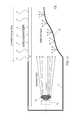
- FIG. 9is an illustration of the light distribution generated by the embodiment shown in FIG. 6 .
- FIG. 10is an illustration of the light distribution generated by the embodiment shown in FIG. 7 .
- Embodiments of the inventionare described herein with reference to illustrations that are schematic illustrations of idealized embodiments (and intermediate structures) of the invention. As such, variations from the shapes of the illustrations as a result, for example, of manufacturing techniques and/or tolerances, are to be expected. Thus, embodiments of the invention should not be construed as limited to the particular shapes of regions illustrated herein but are to include deviations in shapes that result, for example, from manufacturing.
- FIG. 1is a side elevation view of an exemplary embodiment of an airguide backlight assembly.
- An anterior element 10may be positioned at the front portion of the assembly (i.e. the anterior side of the backlight assembly that would face an intended observer) and may include any one or a combination of the following: clear or frosted glass or plastic, a diffusing element, brightness enhancing films, anti-reflective films, liquid crystal cells, posters/static graphics, etc.
- the anterior element 10is at least semi-transparent.
- the light source 15is positioned along the edge of the assembly, preferably with another light source 15 on the opposing side.
- a lens 20is preferably positioned in front of the light source 15 and may be used to at least partially collimate the light.
- lensthere are no practical limits on the type of lens that may be used with the embodiments herein, assuming that a lens is required for the chosen light source. This may include convex-convex, plano-convex, cylindrical rods, gradient-index, and Fresnel lens.
- a reflective pan 30is positioned behind the anterior element 10 and within the path of the light passing through the lens 20 .
- the reflective pan 30has a simple ramp design where two primary variables control the performance of the reflective pan 30 : a Center Gap (CG) and an Edge Gap (EG).
- the Center Gap (CG)may be defined as the distance from the pan 30 to the rear surface of the anterior element 10 , when measured along the Centerline (CL).
- the Edge Gap (EG)may be defined as the distance from the pan 30 to the rear surface of the anterior element 10 , when measured at the edge of the pan 30 and anterior element 10 where the light source 15 is positioned.
- the CG distanceis often on the order of 60-90% of the EG distance.
- FIG. 2is a partial side elevation view of an embodiment of an airguide backlight assembly using a reflective pan 31 having an optimized curvature 32 .
- An optimized curvaturewould generally serve to transform the distribution of light as it exits the light source 20 to the desired distribution of light over the viewing area, which is typically a uniform distribution.
- the distribution of light as it exits the light source at 20is generally not uniform.
- the shape of the pan 32is designed to compensate for the nonuniformity of the light source while simultaneously and conveniently reflecting the light in a predominately outward direction through anterior element 10 .
- the complexity of the shape of the pan 32depends on: 1) the nonuniformity of the light exiting the light source at 20 that must be compensated, and 2) the degree to which the desired viewing area distribution is satisfied. More specifically, the pan may intrinsically reflect more light outward where the light striking it from the light source is weaker, and vice versa. Alternatively and/or simultaneously, in areas where the light striking the pan 32 is relatively stronger the pan 32 may direct light to regions of the viewing area that would otherwise be relatively weaker. A similar effect may be obtained by varying the reflectivity of the pan 32 at different locations along the pan 32 .
- the shape of the pan 32is shown as being contiguous, this is not strictly a requirement. In other words, the shape may have discontinuities such as bent edges, or even formed in discrete sections.
- the surface texture of the pan 32is another variable that can be used to optimize the distribution of light at the viewing area.
- a smoother texturewill tend to ‘specularly’ reflect light like a common mirror does, while a rougher texture will ‘broadcast’ the light over a wider range of angles.
- the surface texturemay also vary at different locations along the pan 32 .
- FIG. 3is a partial side elevation view of an embodiment of an airguide backlight assembly using blinders 100 around the light source 15 .
- the blinders 100are preferably placed above and below the light source 15 and lens 20 .
- a top blindermay be positioned between the anterior element 10 and the light source 15 while a bottom blinder may be positioned between the pan 31 and the light source 15 .
- the blinders 100may have any value of reflectivity, from 0-100%, which serves to aid in the desired distribution of light at the viewing area.
- a preferred use of blinders 100is to selectively control stray light as it exits the light source at 20 .
- FIG. 4is a partial side elevation view of an embodiment of an airguide backlight assembly showing the variables in the design which can be used for optimization.
- FIG. 5is a partial side elevation view of an embodiment of an airguide backlight assembly showing further variables in the design, including a light source 15 having its optical axis positioned at an angle relative to the anterior element 10 .
- FIG. 6is a partial side elevation view of an embodiment of an airguide backlight assembly using a simple ramped reflective pan 30 and a simple rod that serves as the lens 50 .
- This embodimentillustrates, by way of example, the invention in perhaps its most simplistic form.
- FIG. 7is a partial side elevation view of an embodiment of an airguide backlight assembly using a cylindrical reflective pan 35 and a rod lens 50 .
- FIG. 8is a partial side elevation view of an embodiment of an airguide backlight assembly using a hybrid curved ramped reflective pan 36 , which begins with a ramp section 37 and transitions to a curved section 38 as you approach the centerline of the backlight assembly.
- FIG. 9is an illustration of the light distribution generated by the embodiment shown in FIG. 6 .
- This illustrationwas produced using light modeling software ASAP, which is available from Breault Research Organization. This simulation was performed with no diffuser placed into the model.
- FIG. 10is an illustration of the light distribution generated by the embodiment shown in FIG. 7 . This simulation was performed with no diffuser placed into the model.
Landscapes
- Physics & Mathematics (AREA)
- General Physics & Mathematics (AREA)
- Optics & Photonics (AREA)
- Nonlinear Science (AREA)
- Mathematical Physics (AREA)
- Chemical & Material Sciences (AREA)
- Crystallography & Structural Chemistry (AREA)
- Planar Illumination Modules (AREA)
Abstract
Description
Claims (23)
Priority Applications (2)
| Application Number | Priority Date | Filing Date | Title |
|---|---|---|---|
| US14/322,962US9690137B2 (en) | 2013-07-03 | 2014-07-03 | Airguide backlight assembly |
| US15/594,277US10466539B2 (en) | 2013-07-03 | 2017-05-12 | Airguide backlight assembly |
Applications Claiming Priority (2)
| Application Number | Priority Date | Filing Date | Title |
|---|---|---|---|
| US201361842704P | 2013-07-03 | 2013-07-03 | |
| US14/322,962US9690137B2 (en) | 2013-07-03 | 2014-07-03 | Airguide backlight assembly |
Related Child Applications (1)
| Application Number | Title | Priority Date | Filing Date |
|---|---|---|---|
| US15/594,277ContinuationUS10466539B2 (en) | 2013-07-03 | 2017-05-12 | Airguide backlight assembly |
Publications (2)
| Publication Number | Publication Date |
|---|---|
| US20150009653A1 US20150009653A1 (en) | 2015-01-08 |
| US9690137B2true US9690137B2 (en) | 2017-06-27 |
Family
ID=52132680
Family Applications (2)
| Application Number | Title | Priority Date | Filing Date |
|---|---|---|---|
| US14/322,962Expired - Fee RelatedUS9690137B2 (en) | 2013-07-03 | 2014-07-03 | Airguide backlight assembly |
| US15/594,277Active2035-01-05US10466539B2 (en) | 2013-07-03 | 2017-05-12 | Airguide backlight assembly |
Family Applications After (1)
| Application Number | Title | Priority Date | Filing Date |
|---|---|---|---|
| US15/594,277Active2035-01-05US10466539B2 (en) | 2013-07-03 | 2017-05-12 | Airguide backlight assembly |
Country Status (2)
| Country | Link |
|---|---|
| US (2) | US9690137B2 (en) |
| WO (1) | WO2015003130A1 (en) |
Families Citing this family (14)
| Publication number | Priority date | Publication date | Assignee | Title |
|---|---|---|---|---|
| EP2438588A4 (en) | 2009-06-03 | 2013-01-16 | Mri Inc | Dynamic dimming led backlight |
| US9348174B2 (en) | 2013-03-14 | 2016-05-24 | Manufacturing Resources International, Inc. | Rigid LCD assembly |
| US9690137B2 (en) | 2013-07-03 | 2017-06-27 | Manufacturing Resources International, Inc. | Airguide backlight assembly |
| US10191212B2 (en) | 2013-12-02 | 2019-01-29 | Manufacturing Resources International, Inc. | Expandable light guide for backlight |
| US10527276B2 (en) | 2014-04-17 | 2020-01-07 | Manufacturing Resources International, Inc. | Rod as a lens element for light emitting diodes |
| US10649273B2 (en) | 2014-10-08 | 2020-05-12 | Manufacturing Resources International, Inc. | LED assembly for transparent liquid crystal display and static graphic |
| US10261362B2 (en) | 2015-09-01 | 2019-04-16 | Manufacturing Resources International, Inc. | Optical sheet tensioner |
| FR3040467B1 (en)* | 2015-09-02 | 2020-07-17 | Normalu | LIGHT STRUCTURE INCLUDING INDIRECT LIGHTING |
| EP3185071B1 (en)* | 2015-12-23 | 2019-10-09 | Samsung Electronics Co., Ltd. | Display apparatus |
| JP6613906B2 (en)* | 2016-01-13 | 2019-12-04 | 富士ゼロックス株式会社 | Light guide, static eliminator, and image forming apparatus |
| TWI579622B (en)* | 2016-08-12 | 2017-04-21 | 揚昇照明股份有限公司 | Light source module and display apparatus |
| US11061281B2 (en) | 2019-08-20 | 2021-07-13 | Tcl China Star Optoelectronics Technology Co., Ltd. | Backlight module and display device |
| CN110515236A (en)* | 2019-08-20 | 2019-11-29 | 深圳市华星光电技术有限公司 | Backlight module and display device |
| US12429726B1 (en) | 2023-10-02 | 2025-09-30 | Manufacturing Resources International, Inc. | Optical stack with a liquid crystal layer and a micro lens array, electronic display assembly, and related methods |
Citations (15)
| Publication number | Priority date | Publication date | Assignee | Title |
|---|---|---|---|---|
| US4257084A (en)* | 1979-02-21 | 1981-03-17 | Reynolds Christopher H | Display device |
| US5040878A (en)* | 1990-01-26 | 1991-08-20 | Dimension Technologies, Inc. | Illumination for transmissive displays |
| US5046805A (en)* | 1990-07-16 | 1991-09-10 | Simon Jerome H | Tapered optical waveguides for uniform energy (light) distribution including energy bridging |
| US5453855A (en)* | 1992-12-15 | 1995-09-26 | Koito Manufacturing Co., Ltd. | Liquid crystal display device backlit by LED's coupled to printed circuit board |
| US5528720A (en)* | 1992-03-23 | 1996-06-18 | Minnesota Mining And Manufacturing Co. | Tapered multilayer luminaire devices |
| US20020043012A1 (en)* | 2000-09-28 | 2002-04-18 | Minoru Shibata | Illumination apparatus |
| US6481130B1 (en)* | 2000-08-11 | 2002-11-19 | Leotek Electronics Corporation | Light emitting diode linear array with lens stripe for illuminated signs |
| US20040062029A1 (en)* | 2002-09-17 | 2004-04-01 | Nec Lcd Technologies, Ltd. | Backlight for a double-sided liquid crystal display unit |
| US7473019B2 (en)* | 2005-09-29 | 2009-01-06 | Osram Opto Semiconductors Gmbh | Lighting apparatus |
| US20090196069A1 (en)* | 2006-01-23 | 2009-08-06 | Fujifilm Corporation | Planar lighting device |
| US20100253613A1 (en) | 2008-10-02 | 2010-10-07 | Manufacturing Resources International, Inc. | Led backlight and electronic control |
| US20120134139A1 (en) | 2010-11-25 | 2012-05-31 | Jang Ji Won | Backlight unit and display apparatus using the same |
| US20120250329A1 (en)* | 2011-03-30 | 2012-10-04 | Toyoda Gosei Co., Ltd. | Light emitting device |
| US20120275023A1 (en) | 2009-10-24 | 2012-11-01 | Weber Michael F | Immersed reflective polarizer with angular confinement in selected planes of incidence |
| US20120314447A1 (en)* | 2011-06-08 | 2012-12-13 | Shenzhen China Star Optoelectronics Technology Co., Ltd. | Backlight module and liquid crystal display device |
Family Cites Families (186)
| Publication number | Priority date | Publication date | Assignee | Title |
|---|---|---|---|---|
| US1812919A (en) | 1930-05-16 | 1931-07-07 | Milton C Balder | Electric sign |
| US3510973A (en) | 1968-04-10 | 1970-05-12 | Translucent Display Corp | Illuminated display |
| IN152010B (en) | 1979-04-24 | 1983-09-24 | Director General Cement Resear | |
| FR2585167B1 (en) | 1985-07-19 | 1993-05-07 | Gen Electric | REDUNDANT CONDUCTIVE STRUCTURES FOR LIQUID CRYSTAL DISPLAYS CONTROLLED BY THIN FILM FIELD EFFECT TRANSISTORS |
| US4888599A (en) | 1987-10-23 | 1989-12-19 | Rockwell International Corp. | Real time apparatus for adjusting contrast ratio of liquid crystal displays |
| JPH01191829A (en) | 1988-01-27 | 1989-08-01 | Mitsubishi Electric Corp | Liquid crystal display device |
| US5592482A (en) | 1989-04-28 | 1997-01-07 | Abraham; Charles | Video distribution system using in-wall wiring |
| US5363149A (en) | 1992-04-23 | 1994-11-08 | Pioneer Electronic Corporation | Projection television set |
| US5440324A (en) | 1992-12-30 | 1995-08-08 | Avionic Displays Corporation | Backlighting for liquid crystal display |
| US5661578A (en) | 1993-07-27 | 1997-08-26 | Honeywell Inc. | Color liquid crystal display backlight system for night vision imaging system compatibility |
| JPH07262810A (en) | 1994-03-18 | 1995-10-13 | Sony Tektronix Corp | Luminous device |
| KR100198543B1 (en) | 1995-12-27 | 1999-06-15 | 구자홍 | LCD Display |
| JPH1124584A (en) | 1997-07-04 | 1999-01-29 | Stanley Electric Co Ltd | Backlight device for liquid crystal display |
| JPH1195214A (en) | 1997-09-22 | 1999-04-09 | Toshiba Electronic Engineering Corp | Planar display device |
| US6266476B1 (en) | 1998-08-25 | 2001-07-24 | Physical Optics Corporation | Optical element having an integral surface diffuser |
| US6166389A (en) | 1998-08-25 | 2000-12-26 | Physical Optics Corporation | Apparatus having a light source and a sol-gel monolithic diffuser |
| JP2000081848A (en) | 1998-09-03 | 2000-03-21 | Semiconductor Energy Lab Co Ltd | Electronic equipment mounting liquid crystal display device |
| KR100318539B1 (en) | 1999-03-24 | 2001-12-22 | 윤종용 | thin film transistor panels for liquid crystal displays |
| DE19930174A1 (en) | 1999-06-30 | 2001-01-04 | Patent Treuhand Ges Fuer Elektrische Gluehlampen Mbh | Control circuit for LED and associated operating method |
| JP2001166150A (en) | 1999-12-13 | 2001-06-22 | Nitto Denko Corp | Light guide plate, surface light source device and liquid crystal display device |
| JP2001188230A (en) | 1999-12-28 | 2001-07-10 | Fuji Photo Film Co Ltd | Liquid crystal display device |
| US7049761B2 (en) | 2000-02-11 | 2006-05-23 | Altair Engineering, Inc. | Light tube and power supply circuit |
| JP3973827B2 (en) | 2000-08-14 | 2007-09-12 | Necディスプレイソリューションズ株式会社 | Color adjustment method and apparatus |
| US6636003B2 (en) | 2000-09-06 | 2003-10-21 | Spectrum Kinetics | Apparatus and method for adjusting the color temperature of white semiconduct or light emitters |
| US6419372B1 (en) | 2000-09-08 | 2002-07-16 | Rockwell Collins, Inc. | Compact optical wave-guide system for LED backlighting liquid crystal displays |
| JP3687034B2 (en) | 2000-12-29 | 2005-08-24 | 東京特殊電線株式会社 | Display device color calibration device and display device |
| US6601984B2 (en) | 2001-02-14 | 2003-08-05 | Estec Co., Ltd. | LED illuminating device and lighting apparatus employing the same |
| TW579491B (en) | 2001-03-06 | 2004-03-11 | Ibm | Liquid crystal display device and display device |
| ATE385337T1 (en) | 2001-07-03 | 2008-02-15 | Barco Nv | METHOD AND DEVICE FOR REAL-TIME CORRECTION OF AN IMAGE |
| US7040794B2 (en) | 2001-07-12 | 2006-05-09 | Northrop Grumman Corporation | Programmable multi-color backlight for a liquid crystal display |
| JP2003043481A (en) | 2001-07-31 | 2003-02-13 | Nec Corp | Backlight unit and liquid crystal display device using the same |
| TW567619B (en) | 2001-08-09 | 2003-12-21 | Matsushita Electric Industrial Co Ltd | LED lighting apparatus and card-type LED light source |
| JP3931070B2 (en) | 2001-10-22 | 2007-06-13 | 株式会社アドバンスト・ディスプレイ | Planar light source device and liquid crystal display device including the same |
| US6936968B2 (en) | 2001-11-30 | 2005-08-30 | Mule Lighting, Inc. | Retrofit light emitting diode tube |
| KR100417916B1 (en) | 2001-12-29 | 2004-02-14 | 엘지.필립스 엘시디 주식회사 | Array Panel for Liquid Crystal Display Device |
| JP4348457B2 (en) | 2002-03-13 | 2009-10-21 | ドルビー ラボラトリーズ ライセンシング コーポレイション | High dynamic range display, display controller, and image display method |
| JP2004004581A (en) | 2002-04-04 | 2004-01-08 | Seiko Epson Corp | Heat radiating member, lighting device, electro-optical device and electronic equipment |
| JP2004012872A (en) | 2002-06-07 | 2004-01-15 | Nec Electronics Corp | Display device and its driving method |
| US6860628B2 (en) | 2002-07-17 | 2005-03-01 | Jonas J. Robertson | LED replacement for fluorescent lighting |
| US6842204B1 (en) | 2002-09-06 | 2005-01-11 | Rockwell Collins | Color display system for NVIS Class A compatibility |
| US6762815B2 (en) | 2002-12-12 | 2004-07-13 | Hannstar Display Corp. | In-plane switching LCD with a redundancy structure for an opened common electrode and a high storage capacitance |
| JP2004193029A (en) | 2002-12-13 | 2004-07-08 | Advanced Display Inc | Light source device and display device |
| US7363000B2 (en) | 2002-12-13 | 2008-04-22 | Agere Systems Inc. | Method, system, and computer program product for providing multi-tiered broadcasting services |
| JP3698139B2 (en) | 2002-12-20 | 2005-09-21 | セイコーエプソン株式会社 | ELECTRO-OPTICAL DEVICE WITH MOUNTING CASE, PROJECTION TYPE DISPLAY DEVICE, AND MOUNTING CASE |
| US7015650B2 (en) | 2003-03-10 | 2006-03-21 | Leddynamics | Circuit devices, circuit devices which include light emitting diodes, assemblies which include such circuit devices, flashlights which include such assemblies, and methods for directly replacing flashlight bulbs |
| US6789921B1 (en) | 2003-03-25 | 2004-09-14 | Rockwell Collins | Method and apparatus for backlighting a dual mode liquid crystal display |
| US7012379B1 (en) | 2003-03-27 | 2006-03-14 | Ilight Technologies, Inc. | Cuttable illumination device |
| EP1619648A4 (en) | 2003-03-28 | 2008-08-06 | Sharp Kk | Display device |
| KR100563049B1 (en) | 2003-10-07 | 2006-03-24 | 삼성에스디아이 주식회사 | Plasma display device having heat insulation means |
| US7218812B2 (en) | 2003-10-27 | 2007-05-15 | Rpo Pty Limited | Planar waveguide with patterned cladding and method for producing the same |
| US7025474B2 (en) | 2003-11-03 | 2006-04-11 | Honeywell International Inc. | Dual mode display with a backlight filter for an unactivated light emitting diode (LED) |
| US7057590B2 (en) | 2003-11-04 | 2006-06-06 | Infineon Technologies Ag | LED array implementation |
| TWM254613U (en) | 2003-11-14 | 2005-01-01 | Litemax Electronics Inc | Backlight module of liquid crystal display |
| US7053560B1 (en) | 2003-11-17 | 2006-05-30 | Dr. Led (Holdings), Inc. | Bi-directional LED-based light |
| US8400430B2 (en) | 2003-11-21 | 2013-03-19 | American Panel Corporation | Display device with integral touch panel surface |
| JP4042687B2 (en) | 2003-12-15 | 2008-02-06 | ソニー株式会社 | Lighting device and backlight device |
| KR100606968B1 (en) | 2003-12-29 | 2006-08-01 | 엘지.필립스 엘시디 주식회사 | Back light unit of display device and liquid crystal display device using same |
| JP2005228996A (en) | 2004-02-13 | 2005-08-25 | Matsushita Electric Works Ltd | Light-emitting device |
| JP4077799B2 (en) | 2004-02-18 | 2008-04-23 | アバゴ・テクノロジーズ・イーシービーユー・アイピー(シンガポール)プライベート・リミテッド | Color-correctable display system |
| US7795574B2 (en) | 2004-02-23 | 2010-09-14 | Xenonics, Inc. | Low-light viewing device for displaying image based on visible and near infrared light |
| US7830472B2 (en) | 2004-04-26 | 2010-11-09 | Mitsubishi Chemical Corporation | Blue color composition for color filter, color filter, and color image display device |
| US7307614B2 (en) | 2004-04-29 | 2007-12-11 | Micrel Inc. | Light emitting diode driver circuit |
| JP4063249B2 (en) | 2004-05-19 | 2008-03-19 | ソニー株式会社 | Illumination device and liquid crystal display device |
| WO2005119124A2 (en) | 2004-05-26 | 2005-12-15 | Gelcore Llc | Led lighting systems for product display cases |
| KR20060000313A (en) | 2004-06-28 | 2006-01-06 | 루미마이크로 주식회사 | Method for producing a color conversion light-emitting device comprising a large particle fluorescent powder and a resin composition used therein |
| US20060012985A1 (en) | 2004-07-15 | 2006-01-19 | Eastman Kodak Company | Flat panel lighting for enclosed space illumination |
| JP4590977B2 (en) | 2004-08-18 | 2010-12-01 | ソニー株式会社 | Backlight device and transmissive liquid crystal display device |
| TWI239666B (en) | 2004-09-16 | 2005-09-11 | Chen-Lun Hsingchen | LED package with diode protection circuit |
| US7436469B2 (en) | 2004-10-15 | 2008-10-14 | 3M Innovative Properties Company | Composite diffuser plates and direct-lit liquid crystal displays using same |
| CA2583749A1 (en) | 2004-10-25 | 2006-05-04 | Rpo Pty Limited | Planar lenses for integrated optics |
| TWI326443B (en) | 2004-10-27 | 2010-06-21 | Chunghwa Picture Tubes Ltd | Dynamic gamma correction circuit, method thereof and plane display device |
| KR101167301B1 (en) | 2004-10-30 | 2012-07-19 | 엘지디스플레이 주식회사 | Back light unit of liquid crystal display device |
| KR101157233B1 (en) | 2004-10-30 | 2012-06-15 | 엘지디스플레이 주식회사 | Apparatus of light emitting diode backlight and liquid crystal display device using thereof |
| JP4539492B2 (en) | 2004-11-19 | 2010-09-08 | ソニー株式会社 | Backlight device, backlight driving method, and liquid crystal display device |
| EP1831742A4 (en) | 2004-12-09 | 2008-05-14 | Rpo Pty Ltd | Optical power distribution devices |
| US7333027B2 (en) | 2004-12-15 | 2008-02-19 | Lumination Llc | Power supply for LED signal |
| ES2557159T3 (en) | 2004-12-23 | 2016-01-22 | Nualight Limited | Display case lighting |
| CN101194222A (en) | 2005-02-07 | 2008-06-04 | Rpo私人有限公司 | Waveguide design incorporating reflective optics |
| US20060197474A1 (en) | 2005-03-07 | 2006-09-07 | Olsen Jeremy E | Modular lighting system |
| KR20060104078A (en) | 2005-03-29 | 2006-10-09 | 삼성전자주식회사 | Backlight unit and liquid crystal display including the same |
| WO2006109237A1 (en) | 2005-04-14 | 2006-10-19 | Philips Intellectual Property & Standards Gmbh | Color control of white led lamps |
| JP2006302710A (en) | 2005-04-21 | 2006-11-02 | Toshiba Matsushita Display Technology Co Ltd | Surface light source device |
| KR20060120373A (en) | 2005-05-19 | 2006-11-27 | 삼성전자주식회사 | Backlight unit and LCD using the same |
| KR101187204B1 (en) | 2005-06-08 | 2012-10-02 | 삼성디스플레이 주식회사 | Backlight assembly for simplifying assembling and display device provided with the same, and the assembling method of the backlight assembly |
| KR20060134375A (en) | 2005-06-22 | 2006-12-28 | 삼성전자주식회사 | Back light assembly and display device having same |
| JP2007027099A (en) | 2005-07-13 | 2007-02-01 | Samsung Electronics Co Ltd | Backlight assembly, display substrate, display device having the same, display substrate, and manufacturing method thereof |
| US7347706B1 (en) | 2005-07-21 | 2008-03-25 | Leotek Electronics Corporation | Light emitting diode (LED) based street light and other lighting applications |
| JP3979424B2 (en) | 2005-09-09 | 2007-09-19 | 松下電工株式会社 | Light emitting device |
| WO2007048180A1 (en) | 2005-10-24 | 2007-05-03 | Rpo Pty Limited | Improved optical elements for waveguide-based optical touch screens |
| JP2009512178A (en) | 2005-11-04 | 2009-03-19 | パナソニック株式会社 | LIGHT EMITTING MODULE AND DISPLAY DEVICE AND LIGHTING DEVICE USING THE SAME |
| US20070115686A1 (en) | 2005-11-23 | 2007-05-24 | Luc Tyberghien | Lighting assembly, backlight assembly, display panel, and methods of temperature control |
| KR100764380B1 (en) | 2005-12-16 | 2007-10-08 | 삼성전기주식회사 | Slim backlight unit |
| US20070139574A1 (en) | 2005-12-19 | 2007-06-21 | Byung-Soo Ko | Plateless LCD Unit |
| US20070147037A1 (en) | 2005-12-22 | 2007-06-28 | Dynascan Technology Corp. | Super slim LCD backlight device using uniforming chamber |
| KR101237788B1 (en) | 2005-12-29 | 2013-02-28 | 엘지디스플레이 주식회사 | LED light emitting unit and LED backlight assembly and liquid crystal display module |
| EP1976030A1 (en) | 2006-01-04 | 2008-10-01 | Rohm Co., Ltd. | Thin-type light emitting diode lamp, and its manufacturing |
| KR101248899B1 (en) | 2006-01-20 | 2013-04-01 | 엘지디스플레이 주식회사 | Liquid crystal display device module |
| US7525611B2 (en) | 2006-01-24 | 2009-04-28 | Astronautics Corporation Of America | Night vision compatible display backlight |
| KR20070079649A (en) | 2006-02-03 | 2007-08-08 | 삼성전자주식회사 | Backlight Assembly and Display Device Having Same |
| US7307391B2 (en) | 2006-02-09 | 2007-12-11 | Led Smart Inc. | LED lighting system |
| JP2009526130A (en) | 2006-02-10 | 2009-07-16 | オプレント エレクトロニクス インターナショナル ピーティーイー エルティーディー | Anodized aluminum, dielectrics and methods |
| EP1987701A1 (en) | 2006-02-14 | 2008-11-05 | Koninklijke Philips Electronics N.V. | Lighting device with controllable light intensity |
| KR100735453B1 (en) | 2006-02-22 | 2007-07-04 | 삼성전기주식회사 | White light emitting device |
| US20070195535A1 (en) | 2006-02-23 | 2007-08-23 | Anthony, Inc. | Reflector system for led illuminated display case |
| JP5011758B2 (en) | 2006-03-06 | 2012-08-29 | セイコーエプソン株式会社 | projector |
| KR101263502B1 (en) | 2006-03-27 | 2013-05-13 | 엘지디스플레이 주식회사 | Light Emitting Diode Back Light Unit and Liquid Crystal Display Device having thereof |
| US7393129B2 (en) | 2006-03-29 | 2008-07-01 | 3M Innovative Properties Company | Optical film assemblies and methods of making same |
| WO2007128039A1 (en) | 2006-05-01 | 2007-11-15 | Rpo Pty Limited | Waveguide materials for optical touch screens |
| US8529993B2 (en) | 2006-05-01 | 2013-09-10 | Zetta Research andDevelopment LLC—RPO Series | Low volatility polymers for two-stage deposition processes |
| US7811640B2 (en) | 2006-05-02 | 2010-10-12 | Rpo Pty Limited | Methods for fabricating polymer optical waveguides on large area panels |
| US7825891B2 (en) | 2006-06-02 | 2010-11-02 | Apple Inc. | Dynamic backlight control system |
| KR101239823B1 (en) | 2006-06-26 | 2013-03-06 | 엘지디스플레이 주식회사 | Backlight unit for Liquid Crystal Display device using thereof |
| JP4798006B2 (en) | 2006-06-30 | 2011-10-19 | ソニー株式会社 | Backlight device, liquid crystal display device, and electronic device |
| US8201977B2 (en) | 2008-10-07 | 2012-06-19 | Electraled, Inc. | LED illuminated member within a refrigerated display case |
| JP4151717B2 (en) | 2006-07-21 | 2008-09-17 | ソニー株式会社 | Light source module, light source device, and liquid crystal display device |
| KR20080013592A (en) | 2006-08-09 | 2008-02-13 | 삼성전자주식회사 | Backlight unit and display device including same |
| US20080049164A1 (en) | 2006-08-22 | 2008-02-28 | Samsung Electronics Co., Ltd., | Backlight assembly, manufacturing method thereof, and liquid crystal display device |
| WO2008034184A1 (en) | 2006-09-22 | 2008-03-27 | Rpo Pty Limited | Waveguide configurations for optical touch systems |
| AU2007216782A1 (en) | 2006-09-22 | 2008-04-10 | Rpo Pty Ltd | Optical elements for waveguide-based optical touch input devices |
| US20080089064A1 (en) | 2006-10-17 | 2008-04-17 | Baoliang Wang | LED Illuminating device |
| US20080101086A1 (en) | 2006-10-26 | 2008-05-01 | K Laser Technology, Inc. | Led backlight with bare chip led |
| TWI345661B (en) | 2006-10-30 | 2011-07-21 | Coretronic Corp | Backlight module |
| US20080106527A1 (en) | 2006-11-06 | 2008-05-08 | Rpo Pty Limited | Waveguide Configurations for Minimising Substrate Area |
| US8064744B2 (en) | 2006-11-10 | 2011-11-22 | Rpo Pty Limited | Planar waveguide lens design |
| DE602007007804D1 (en) | 2006-11-10 | 2010-08-26 | Philips Solid State Lighting | METHOD AND DEVICE FOR CONTROLLING REAR-OPERATED LED |
| JP2008140704A (en) | 2006-12-04 | 2008-06-19 | Stanley Electric Co Ltd | LED backlight |
| KR100930171B1 (en) | 2006-12-05 | 2009-12-07 | 삼성전기주식회사 | White light emitting device and white light source module using same |
| JP5092408B2 (en) | 2007-01-11 | 2012-12-05 | ソニー株式会社 | Backlight device and display device |
| KR100993383B1 (en) | 2007-03-15 | 2010-11-09 | 제일모직주식회사 | Diffuser prism sheet including light diffuser formed on valley portion of prism and liquid crystal display device using same |
| US7597468B2 (en) | 2007-03-23 | 2009-10-06 | Promate Electronic Co., Ltd. | Light source of side-edge type LED backlight unit |
| JP2008256819A (en) | 2007-04-03 | 2008-10-23 | Toppan Printing Co Ltd | Color filter for liquid crystal display device and liquid crystal display device |
| US8842366B2 (en) | 2007-05-11 | 2014-09-23 | Zetta Research and Development LLC—RPO Series | Transmissive body |
| US7827712B2 (en) | 2007-05-11 | 2010-11-09 | Hines Stephen P | Lighted signage using reflected light behind the signage |
| KR101375851B1 (en) | 2007-06-01 | 2014-04-01 | 엘지디스플레이 주식회사 | Liquid crystal display device |
| US20090002990A1 (en) | 2007-06-29 | 2009-01-01 | Aaron James Becker | Led lighting assemblies for display cases |
| US8810501B2 (en) | 2007-07-04 | 2014-08-19 | Koninklijke Philips N.V. | Method and system for driving a backlight in a display |
| US20090033612A1 (en) | 2007-07-31 | 2009-02-05 | Roberts John K | Correction of temperature induced color drift in solid state lighting displays |
| JP2009036964A (en) | 2007-08-01 | 2009-02-19 | Toppan Printing Co Ltd | Liquid crystal display |
| US8104911B2 (en) | 2007-09-28 | 2012-01-31 | Apple Inc. | Display system with distributed LED backlight |
| KR20090032812A (en) | 2007-09-28 | 2009-04-01 | 삼성전자주식회사 | Display device and control method |
| JP2009128686A (en) | 2007-11-26 | 2009-06-11 | Sony Corp | Display apparatus and electronic device |
| KR101421626B1 (en) | 2008-01-09 | 2014-07-22 | 삼성디스플레이 주식회사 | Light source unit and backlight unit and liquid crystal display having the same |
| US8351013B2 (en) | 2008-03-03 | 2013-01-08 | Manufacturing Resources International, Inc. | Combined serial/parallel light configuration and single layer PCB containing the same |
| US20090243501A1 (en) | 2008-03-26 | 2009-10-01 | Manufacturing Resources International, Inc. | Combined serial/parallel light configuration |
| US8497972B2 (en) | 2009-11-13 | 2013-07-30 | Manufacturing Resources International, Inc. | Thermal plate with optional cooling loop in electronic display |
| JP2009231473A (en) | 2008-03-21 | 2009-10-08 | Sharp Corp | Lighting module and electronic apparatus using the same |
| US8233115B2 (en) | 2008-07-25 | 2012-07-31 | Honeywell International Inc. | Flat panel display assembly with improved luminance uniformity and method for constructing the same |
| US20100102735A1 (en) | 2008-10-29 | 2010-04-29 | Chu-Cheng Chang | Led light string with zener diodes or resistors as shunts |
| WO2010048679A1 (en) | 2008-10-31 | 2010-05-06 | Rpo Pty Limited | A transmissive body |
| US20100109553A1 (en) | 2008-11-05 | 2010-05-06 | Chu-Cheng Chang | Led bulb with zener diode, zener diode assembly or resistor connected in series |
| KR20110099134A (en) | 2008-12-18 | 2011-09-06 | 매뉴팩처링 리소시스 인터내셔널 인코포레이티드 | Thermal Control System for Electronic Displays |
| KR101308752B1 (en) | 2008-12-31 | 2013-09-12 | 엘지디스플레이 주식회사 | Liquid crystal display device |
| TW201038114A (en) | 2009-01-23 | 2010-10-16 | Mri Inc | Combined serial/parallel LED configuration and single layer PCB containing the same |
| US8089213B2 (en) | 2009-02-05 | 2012-01-03 | Myung Koo Park | LED fluorescent lamp |
| EP2425465A2 (en) | 2009-04-27 | 2012-03-07 | Manufacturing Resources International, INC. | White led for liquid crystal display backlights |
| EP2438588A4 (en) | 2009-06-03 | 2013-01-16 | Mri Inc | Dynamic dimming led backlight |
| JP5121783B2 (en) | 2009-06-30 | 2013-01-16 | 株式会社日立ハイテクノロジーズ | LED light source, manufacturing method thereof, exposure apparatus using LED light source, and exposure method |
| WO2011044076A2 (en) | 2009-10-05 | 2011-04-14 | American Panel Corporation | Nvis compatible backlight device and lcd using the same |
| US9170007B2 (en) | 2009-10-19 | 2015-10-27 | Jeffrey Allen Erion | LED lighting device and system |
| US8491174B2 (en) | 2010-01-07 | 2013-07-23 | Rambus Delaware Llc | Light emitting assembly |
| US20120062819A1 (en) | 2010-02-10 | 2012-03-15 | Manufacturing Resources International, Inc. | Led circuit with zener diodes |
| TWI408460B (en) | 2010-02-24 | 2013-09-11 | Au Optronics Corp | Optoelectronic device, display and back light module |
| WO2011125363A1 (en) | 2010-04-07 | 2011-10-13 | シャープ株式会社 | Organic electroluminescence element, organic electroluminescence display, and organic electroluminescence display apparatus |
| US9128250B2 (en) | 2010-05-21 | 2015-09-08 | Zetta Research and Development LLC—RPO Series | Optical systems for infrared touch screens |
| US8294168B2 (en) | 2010-06-04 | 2012-10-23 | Samsung Electronics Co., Ltd. | Light source module using quantum dots, backlight unit employing the light source module, display apparatus, and illumination apparatus |
| US8611077B2 (en) | 2010-08-27 | 2013-12-17 | Apple Inc. | Electronic devices with component mounting structures |
| US9121595B2 (en) | 2010-10-18 | 2015-09-01 | Jeffrey Allen Erion | LED lighting device and system |
| US8786799B2 (en) | 2010-11-22 | 2014-07-22 | Wistron Corporation | Liquid crystal display device and electronic equipment having the same |
| KR101177480B1 (en) | 2011-02-14 | 2012-08-24 | 엘지전자 주식회사 | Lighting apparatus and display device comprising the same |
| WO2012133312A1 (en) | 2011-03-31 | 2012-10-04 | シャープ株式会社 | Backlight unit |
| GB201109065D0 (en) | 2011-05-31 | 2011-07-13 | Nanoco Technologies Ltd | Semiconductor nanoparticle-containing materials and light emitting devices incorporating the same |
| US20120327039A1 (en) | 2011-06-27 | 2012-12-27 | Rpo Pty Ltd | Infrared touch screen with simplified components |
| KR101357583B1 (en) | 2011-07-29 | 2014-02-05 | 엘지이노텍 주식회사 | Lamp device within resin layer for light-guide and LCD using the same |
| JP5451711B2 (en) | 2011-10-14 | 2014-03-26 | 株式会社ジャパンディスプレイ | Display device |
| US20130278868A1 (en) | 2011-12-07 | 2013-10-24 | Manufacturing Resources International, Inc. | Optically Isolated Cavity For Light Sensor Feedback in LCD |
| KR101859413B1 (en) | 2011-12-26 | 2018-05-21 | 삼성디스플레이 주식회사 | A display module and an apparatus having the same |
| US9323087B2 (en) | 2012-08-06 | 2016-04-26 | Sharp Kabushiki Kaisha | Display apparatus and television receiver |
| WO2014034546A1 (en) | 2012-08-31 | 2014-03-06 | シャープ株式会社 | Display apparatus and television receiver |
| US9207484B2 (en) | 2012-09-26 | 2015-12-08 | Apple Inc. | Computer LED bar and thermal architecture features |
| KR102096400B1 (en) | 2012-10-17 | 2020-04-06 | 삼성전자주식회사 | Liquid Crystal Display |
| US9348174B2 (en) | 2013-03-14 | 2016-05-24 | Manufacturing Resources International, Inc. | Rigid LCD assembly |
| US9690137B2 (en) | 2013-07-03 | 2017-06-27 | Manufacturing Resources International, Inc. | Airguide backlight assembly |
| US10191212B2 (en) | 2013-12-02 | 2019-01-29 | Manufacturing Resources International, Inc. | Expandable light guide for backlight |
| IL232888B (en) | 2014-05-29 | 2020-08-31 | Vaynberg Mark | Liquid crystal display backlight |
| US10649273B2 (en) | 2014-10-08 | 2020-05-12 | Manufacturing Resources International, Inc. | LED assembly for transparent liquid crystal display and static graphic |
| US10261362B2 (en) | 2015-09-01 | 2019-04-16 | Manufacturing Resources International, Inc. | Optical sheet tensioner |
- 2014
- 2014-07-03USUS14/322,962patent/US9690137B2/ennot_activeExpired - Fee Related
- 2014-07-03WOPCT/US2014/045405patent/WO2015003130A1/enactiveApplication Filing
- 2017
- 2017-05-12USUS15/594,277patent/US10466539B2/enactiveActive
Patent Citations (15)
| Publication number | Priority date | Publication date | Assignee | Title |
|---|---|---|---|---|
| US4257084A (en)* | 1979-02-21 | 1981-03-17 | Reynolds Christopher H | Display device |
| US5040878A (en)* | 1990-01-26 | 1991-08-20 | Dimension Technologies, Inc. | Illumination for transmissive displays |
| US5046805A (en)* | 1990-07-16 | 1991-09-10 | Simon Jerome H | Tapered optical waveguides for uniform energy (light) distribution including energy bridging |
| US5528720A (en)* | 1992-03-23 | 1996-06-18 | Minnesota Mining And Manufacturing Co. | Tapered multilayer luminaire devices |
| US5453855A (en)* | 1992-12-15 | 1995-09-26 | Koito Manufacturing Co., Ltd. | Liquid crystal display device backlit by LED's coupled to printed circuit board |
| US6481130B1 (en)* | 2000-08-11 | 2002-11-19 | Leotek Electronics Corporation | Light emitting diode linear array with lens stripe for illuminated signs |
| US20020043012A1 (en)* | 2000-09-28 | 2002-04-18 | Minoru Shibata | Illumination apparatus |
| US20040062029A1 (en)* | 2002-09-17 | 2004-04-01 | Nec Lcd Technologies, Ltd. | Backlight for a double-sided liquid crystal display unit |
| US7473019B2 (en)* | 2005-09-29 | 2009-01-06 | Osram Opto Semiconductors Gmbh | Lighting apparatus |
| US20090196069A1 (en)* | 2006-01-23 | 2009-08-06 | Fujifilm Corporation | Planar lighting device |
| US20100253613A1 (en) | 2008-10-02 | 2010-10-07 | Manufacturing Resources International, Inc. | Led backlight and electronic control |
| US20120275023A1 (en) | 2009-10-24 | 2012-11-01 | Weber Michael F | Immersed reflective polarizer with angular confinement in selected planes of incidence |
| US20120134139A1 (en) | 2010-11-25 | 2012-05-31 | Jang Ji Won | Backlight unit and display apparatus using the same |
| US20120250329A1 (en)* | 2011-03-30 | 2012-10-04 | Toyoda Gosei Co., Ltd. | Light emitting device |
| US20120314447A1 (en)* | 2011-06-08 | 2012-12-13 | Shenzhen China Star Optoelectronics Technology Co., Ltd. | Backlight module and liquid crystal display device |
Also Published As
| Publication number | Publication date |
|---|---|
| WO2015003130A1 (en) | 2015-01-08 |
| US20170248823A1 (en) | 2017-08-31 |
| US20150009653A1 (en) | 2015-01-08 |
| US10466539B2 (en) | 2019-11-05 |
Similar Documents
| Publication | Publication Date | Title |
|---|---|---|
| US10466539B2 (en) | Airguide backlight assembly | |
| US10838255B2 (en) | Direct view display device and light unit for direct view display device | |
| CN101351739B (en) | Backlight arrangement for uniform illumination using surface-emitting light source | |
| TWI471615B (en) | Backlight module and its optical lens | |
| CN101487945B (en) | Optical sheet and display device having the same | |
| US8287172B2 (en) | Planar illumination device | |
| CN106170720B (en) | Asymmetric turning film with multiple light sources | |
| JP4873683B2 (en) | Surface light source device | |
| US9310546B2 (en) | Backlight unit and display device having the same | |
| TWI536077B (en) | Optical assembly and back light module | |
| US7470038B2 (en) | Diffuser having optical structures | |
| JP5699375B2 (en) | Surface light source device, transmissive display device | |
| TW201945776A (en) | Wedge lightguide | |
| CN104597553A (en) | Light guide plate | |
| US10488014B2 (en) | Display including switchable backlight and front surface film | |
| CN106796002B (en) | Surface light source lighting device | |
| JP5939107B2 (en) | Surface light source device and transmissive display device | |
| US7314301B2 (en) | Light-emitting device and back light unit with light emitting diodes | |
| WO2014057395A1 (en) | Thin and efficient light guide system | |
| TWM526084U (en) | Display apparatus | |
| JP2012032537A (en) | Optical polarizer, surface light source device, and transmission image display device | |
| TWM446344U (en) | Backlight module and optical lens thereof | |
| JP5939109B2 (en) | Surface light source device and transmissive display device | |
| JP2012032533A (en) | Optical polarizer, surface light source device, and transmission image display device | |
| JP2009163925A (en) | Optical sheet and surface light source device |
Legal Events
| Date | Code | Title | Description |
|---|---|---|---|
| AS | Assignment | Owner name:MANUFACTURING RESOURCES INTERNATIONAL, INC., GEORG Free format text:ASSIGNMENT OF ASSIGNORS INTEREST;ASSIGNORS:DUNN, WILLIAM;PRESLEY, HARRY;REEL/FRAME:033484/0046 Effective date:20140806 | |
| AS | Assignment | Owner name:BANK OF AMERICA, N.A., NORTH CAROLINA Free format text:SECURITY INTEREST;ASSIGNOR:MANUFACTURING RESOURCES INTERNATIONAL, INC.;REEL/FRAME:034375/0074 Effective date:20141125 | |
| AS | Assignment | Owner name:FIFTH THIRD BANK, GEORGIA Free format text:SECURITY INTEREST;ASSIGNOR:MANUFACTURING RESOURCES INTERNATIONAL, INC.;REEL/FRAME:036088/0001 Effective date:20150630 | |
| STCF | Information on status: patent grant | Free format text:PATENTED CASE | |
| AS | Assignment | Owner name:MANUFACTURING RESOURCES INTERNATIONAL, INC, GEORGIA Free format text:RELEASE BY SECURED PARTY;ASSIGNOR:BANK OF AMERICA, N.A., AS ADMINISTRATIVE AGENT;REEL/FRAME:047227/0329 Effective date:20180605 Owner name:MANUFACTURING RESOURCES INTERNATIONAL, INC, GEORGI Free format text:RELEASE BY SECURED PARTY;ASSIGNOR:BANK OF AMERICA, N.A., AS ADMINISTRATIVE AGENT;REEL/FRAME:047227/0329 Effective date:20180605 | |
| AS | Assignment | Owner name:MANUFACTURING RESOURCES INTERNATIONAL, INC, GEORGIA Free format text:RELEASE BY SECURED PARTY;ASSIGNOR:FIFTH THIRD BANK;REEL/FRAME:046924/0379 Effective date:20180612 Owner name:MANUFACTURING RESOURCES INTERNATIONAL, INC, GEORGI Free format text:RELEASE BY SECURED PARTY;ASSIGNOR:FIFTH THIRD BANK;REEL/FRAME:046924/0379 Effective date:20180612 | |
| MAFP | Maintenance fee payment | Free format text:PAYMENT OF MAINTENANCE FEE, 4TH YEAR, LARGE ENTITY (ORIGINAL EVENT CODE: M1551); ENTITY STATUS OF PATENT OWNER: LARGE ENTITY Year of fee payment:4 | |
| FEPP | Fee payment procedure | Free format text:MAINTENANCE FEE REMINDER MAILED (ORIGINAL EVENT CODE: REM.); ENTITY STATUS OF PATENT OWNER: LARGE ENTITY | |
| LAPS | Lapse for failure to pay maintenance fees | Free format text:PATENT EXPIRED FOR FAILURE TO PAY MAINTENANCE FEES (ORIGINAL EVENT CODE: EXP.); ENTITY STATUS OF PATENT OWNER: LARGE ENTITY | |
| STCH | Information on status: patent discontinuation | Free format text:PATENT EXPIRED DUE TO NONPAYMENT OF MAINTENANCE FEES UNDER 37 CFR 1.362 | |
| FP | Lapsed due to failure to pay maintenance fee | Effective date:20250627 |