US9687376B2 - Knee brace having three stimulators for continual electro-acupunctural stimulation; in vivo and in situ tissue engineering - Google Patents
Knee brace having three stimulators for continual electro-acupunctural stimulation; in vivo and in situ tissue engineeringDownload PDFInfo
- Publication number
- US9687376B2 US9687376B2US13/987,549US201313987549AUS9687376B2US 9687376 B2US9687376 B2US 9687376B2US 201313987549 AUS201313987549 AUS 201313987549AUS 9687376 B2US9687376 B2US 9687376B2
- Authority
- US
- United States
- Prior art keywords
- knee brace
- battery
- knee
- acupuncture point
- circuit
- Prior art date
- Legal status (The legal status is an assumption and is not a legal conclusion. Google has not performed a legal analysis and makes no representation as to the accuracy of the status listed.)
- Active - Reinstated
Links
Images


Classifications
- A—HUMAN NECESSITIES
- A61—MEDICAL OR VETERINARY SCIENCE; HYGIENE
- A61F—FILTERS IMPLANTABLE INTO BLOOD VESSELS; PROSTHESES; DEVICES PROVIDING PATENCY TO, OR PREVENTING COLLAPSING OF, TUBULAR STRUCTURES OF THE BODY, e.g. STENTS; ORTHOPAEDIC, NURSING OR CONTRACEPTIVE DEVICES; FOMENTATION; TREATMENT OR PROTECTION OF EYES OR EARS; BANDAGES, DRESSINGS OR ABSORBENT PADS; FIRST-AID KITS
- A61F5/00—Orthopaedic methods or devices for non-surgical treatment of bones or joints; Nursing devices ; Anti-rape devices
- A61F5/01—Orthopaedic devices, e.g. long-term immobilising or pressure directing devices for treating broken or deformed bones such as splints, casts or braces
- A61F5/0102—Orthopaedic devices, e.g. long-term immobilising or pressure directing devices for treating broken or deformed bones such as splints, casts or braces specially adapted for correcting deformities of the limbs or for supporting them; Ortheses, e.g. with articulations
- A61F5/0123—Orthopaedic devices, e.g. long-term immobilising or pressure directing devices for treating broken or deformed bones such as splints, casts or braces specially adapted for correcting deformities of the limbs or for supporting them; Ortheses, e.g. with articulations for the knees
- A—HUMAN NECESSITIES
- A61—MEDICAL OR VETERINARY SCIENCE; HYGIENE
- A61F—FILTERS IMPLANTABLE INTO BLOOD VESSELS; PROSTHESES; DEVICES PROVIDING PATENCY TO, OR PREVENTING COLLAPSING OF, TUBULAR STRUCTURES OF THE BODY, e.g. STENTS; ORTHOPAEDIC, NURSING OR CONTRACEPTIVE DEVICES; FOMENTATION; TREATMENT OR PROTECTION OF EYES OR EARS; BANDAGES, DRESSINGS OR ABSORBENT PADS; FIRST-AID KITS
- A61F5/00—Orthopaedic methods or devices for non-surgical treatment of bones or joints; Nursing devices ; Anti-rape devices
- A61F5/01—Orthopaedic devices, e.g. long-term immobilising or pressure directing devices for treating broken or deformed bones such as splints, casts or braces
- A61F5/0102—Orthopaedic devices, e.g. long-term immobilising or pressure directing devices for treating broken or deformed bones such as splints, casts or braces specially adapted for correcting deformities of the limbs or for supporting them; Ortheses, e.g. with articulations
- A61F5/0104—Orthopaedic devices, e.g. long-term immobilising or pressure directing devices for treating broken or deformed bones such as splints, casts or braces specially adapted for correcting deformities of the limbs or for supporting them; Ortheses, e.g. with articulations without articulation
- A61F5/0106—Orthopaedic devices, e.g. long-term immobilising or pressure directing devices for treating broken or deformed bones such as splints, casts or braces specially adapted for correcting deformities of the limbs or for supporting them; Ortheses, e.g. with articulations without articulation for the knees
- A—HUMAN NECESSITIES
- A61—MEDICAL OR VETERINARY SCIENCE; HYGIENE
- A61N—ELECTROTHERAPY; MAGNETOTHERAPY; RADIATION THERAPY; ULTRASOUND THERAPY
- A61N1/00—Electrotherapy; Circuits therefor
- A61N1/02—Details
- A61N1/04—Electrodes
- A61N1/0404—Electrodes for external use
- A61N1/0408—Use-related aspects
- A61N1/0452—Specially adapted for transcutaneous muscle stimulation [TMS]
- A—HUMAN NECESSITIES
- A61—MEDICAL OR VETERINARY SCIENCE; HYGIENE
- A61N—ELECTROTHERAPY; MAGNETOTHERAPY; RADIATION THERAPY; ULTRASOUND THERAPY
- A61N1/00—Electrotherapy; Circuits therefor
- A61N1/02—Details
- A61N1/04—Electrodes
- A61N1/0404—Electrodes for external use
- A61N1/0408—Use-related aspects
- A61N1/0456—Specially adapted for transcutaneous electrical nerve stimulation [TENS]
- A—HUMAN NECESSITIES
- A61—MEDICAL OR VETERINARY SCIENCE; HYGIENE
- A61N—ELECTROTHERAPY; MAGNETOTHERAPY; RADIATION THERAPY; ULTRASOUND THERAPY
- A61N1/00—Electrotherapy; Circuits therefor
- A61N1/02—Details
- A61N1/04—Electrodes
- A61N1/0404—Electrodes for external use
- A61N1/0472—Structure-related aspects
- A61N1/0484—Garment electrodes worn by the patient
- A—HUMAN NECESSITIES
- A61—MEDICAL OR VETERINARY SCIENCE; HYGIENE
- A61N—ELECTROTHERAPY; MAGNETOTHERAPY; RADIATION THERAPY; ULTRASOUND THERAPY
- A61N1/00—Electrotherapy; Circuits therefor
- A61N1/02—Details
- A61N1/04—Electrodes
- A61N1/05—Electrodes for implantation or insertion into the body, e.g. heart electrode
- A61N1/0502—Skin piercing electrodes
- A—HUMAN NECESSITIES
- A61—MEDICAL OR VETERINARY SCIENCE; HYGIENE
- A61N—ELECTROTHERAPY; MAGNETOTHERAPY; RADIATION THERAPY; ULTRASOUND THERAPY
- A61N1/00—Electrotherapy; Circuits therefor
- A61N1/18—Applying electric currents by contact electrodes
- A61N1/32—Applying electric currents by contact electrodes alternating or intermittent currents
- A61N1/36—Applying electric currents by contact electrodes alternating or intermittent currents for stimulation
- A61N1/36014—External stimulators, e.g. with patch electrodes
- A61N1/36017—External stimulators, e.g. with patch electrodes with leads or electrodes penetrating the skin
- A—HUMAN NECESSITIES
- A61—MEDICAL OR VETERINARY SCIENCE; HYGIENE
- A61N—ELECTROTHERAPY; MAGNETOTHERAPY; RADIATION THERAPY; ULTRASOUND THERAPY
- A61N1/00—Electrotherapy; Circuits therefor
- A61N1/18—Applying electric currents by contact electrodes
- A61N1/32—Applying electric currents by contact electrodes alternating or intermittent currents
- A61N1/36—Applying electric currents by contact electrodes alternating or intermittent currents for stimulation
- A61N1/36014—External stimulators, e.g. with patch electrodes
- A61N1/36021—External stimulators, e.g. with patch electrodes for treatment of pain
Definitions
- This inventionrelates to continual electro-acupunctural stimulation and more specifically to knee braces having three stimulators for continual electro-acupunctural stimulation for in vivo and in situ therapeutic effects on analgesia and tissue regeneration and repair.
- the stimuli delivered by these stimulators to the acupuncture points through the acupuncture needleshave varied in frequency, voltage, current, pulse shape and duration.
- the duration of the electrical stimuliis generally very brief, such as ranging from 10 to 60 minutes.
- One such system and methodcan be found in U.S. Pat. No. 7,200,444 to Gavronsky et al., herein incorporated by reference in its entirety.
- a knee brace for continual electro-acupuncture stimulation systemcomprises a first circuit having a first electrode configured to electrically coupled to acupuncture point “Heting (S 156 )” and a second electrode configured to electrically coupled to acupuncture point “Bladder 40 ”, a second circuit having a third electrode configured to electrically coupled to acupuncture point “Spleen 10 ” and a fourth electrode configured to electrically coupled to acupuncture point “Hsiyen (S 145 )”, and a third circuit having a fifth electrode configured to electrically coupled to acupuncture point “Stomach 34 ” and a sixth electrode configured to electrically coupled to acupuncture point “Stomach 35 ”.
- the first, third, and fifth electrodesare connected to a polarity of voltage, and the second, fourth, and sixth electrodes are connected to an opposite polarity of voltage, such that electric currents flow in a body of a patient to achieve analgesia, cartilage repair and regeneration in the knee joint.
- the electrodes of the knee braceare connected to external controller units enclosing a battery for supplying electric currents, a switch for turning the electric power of the battery on and off, and an electro stimulator for modulating the electric currents supplied by the battery.
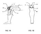
- FIGS. 1A-1Bshow an overview of the continual electro-acupuncture stimulation system applied to produce analgesia, repair and/or regeneration of cartilage in the knee joint.
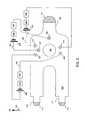
- FIG. 2illustrates a schematic diagram of a knee brace for continual electro-acupuncture stimulation system, according to an embodiment of the invention.
- FIG. 3illustrates a schematic diagram of a knee brace for continual electro-acupuncture stimulation system having a controller unit external to the brace, according to an embodiment of the invention.
- the disclosed treatmentis inexpensive when compared to surgical treatments. This recent biomedical breakthrough is a vast improvement over current treatment modalities, whether measured by cost or by time-to-heal effectiveness.
- a set of electrodes applied externally to certain selected acupuncture points for treating osteoarthritisincluding pain, joint stiffness, limitation of range of motion and limitation of overall function through the use of sub-sensory unidirectional voltage or current pulses.
- the electrical stimuluscan be applied, in one embodiment, through electrodes of three stimulators disposed onto the appropriate anatomical points of the patient such that it is close to the cartilaginous surfaces of an osteoarthritic joint.
- the electrotherapeutic stimulationrestores the normal electromagnetic field enveloping the joint.
- the fieldstimulates chondrocyte functioning, and increases synthesis of proteoglycans and Type II collagen molecules in cartilage resulting in the efficient and efficacious repair of damaged cartilage.
- the devices and methods disclosed hereincan be more efficient and efficacious than, for example, transcutaneous electrical stimulation through non-specifically placed surface electrodes. Articular cartilage and fibrocartilage repair can potentially take place after three to four weeks of continuous treatment.
- FIGS. 1A-1Billustrates some possible advantageous locations to produce analgesia, repair and/or regeneration of cartilage 9 in the knee joint 50 .
- FIG. 1Ais a lateral schematic view of the knee 50 illustrating acupuncture points “Hsiyen (S 145 ) point”, also known as “eye of the knee” 8 , “Heting point (S 156 )” 4 , and “Bladder 40 ” 6 .
- FIG. 1Ais a lateral schematic view of the knee 50 illustrating acupuncture points “Hsiyen (S 145 ) point”, also known as “eye of the knee” 8 , “Heting point (S 156 )” 4 , and “Bladder 40 ” 6 .
- FIG. 1Ais a lateral schematic view of the knee 50 illustrating acupuncture points “Hsiyen (S 145 ) point”, also known as “eye of the knee” 8 , “Heting point (S 156 )” 4 , and “Bla
- FIG. 1Bis a frontal schematic view of the knee illustrating other advantageous acupuncture points for knee analgesia, repair, and/or regeneration of cartilage, such as “Hsiyen (S 145 )” 8 , “Spleen 10 ” 7 , “Heting point (S 156 )” 4 , “Stomach 34 ” 11 , and “Stomach 35 ” 13 .
- These pointscan be located by one of ordinarily skill in the art as described below:
- “Hsiyen (S 145 )” 8Locate this point with knee flexed, at the lower border of the patella in the depression lateral to the patellar ligament.
- “Stomach 34 ” 11Locate this point with knee flexed, two finger-widths (comparable to the patients fingers size) above the medio-superior border of the patella on the bulge of the medial portion of the quadriceps femoris muscle.
- “Stomach 35 ” 13Locate this point in the depression, medial to the patellar ligament, locating the point with the knee flexed.
- “Spleen 10 ” 7Locate this point with the knee flexed, measure two thumb widths (comparable to the patients thumb size) above the latero-superior border of the patella.
- “Bladder 40 ” 6Locate this point at the midpoint of the transverse crease of the popliteal fossa, between the tendons of the biceps femoris and semitendinosus muscles.
- FIG. 2shows a schematic diagram of a knee brace 100 having three stimulators for continual electro-acupuncture stimulation system, according to an embodiment.
- Knee brace 100has a patella-shaped hole 102 for anchoring the knee brace to the knee joint of a patient when knee brace 100 is fixed to the knee. Knee brace is fixed referring to an arrow 104 showing the up direction of the knee. Knee brace 100 comprises non-invasive electrodes 204 , 207 , 211 , 208 , 213 , and 206 .
- electrode 204is configured to electrically coupled to acupuncture point “Heting (S 156 )” 4 ; electrode 207 is configured to electrically coupled to acupuncture point “Spleen 10 ” 7 ; electrode 211 is configured to electrically coupled to acupuncture point “Stomach 34 ” 11 ; electrode 208 is configured to electrically coupled to acupuncture point “Hsiyen (S 145 )” 8 ; electrode 213 is configured to electrically coupled to acupuncture point “Stomach 35 ” 13 ; electrode 206 is configured to electrically coupled to acupuncture point “Bladder 40 ” 6 .
- knee brace 100comprises three individual stimulators 224 , 234 , and 244 in circuits 226 , 236 , and 246 , respectively, as shown in FIG. 2 .
- Electrodes 207 and 208are included in circuit 226 .
- Electrodes 211 and 213are included in circuit 236 .
- Electrodes 204 and 206are included in circuit 246 .
- the polarity of electrodes 207 , 211 , and 204may be positive or negative. Accordingly, the polarity of electrodes 208 , 213 , and 206 may be negative or positive.
- Circuit 226may include a battery 220 or batteries for supplying electric currents that flow through electrode 207 to electrode 208 . Circuit 226 may also include a switch 222 for turning the electric power of battery 220 on and off.
- the electric current from battery 220is modulated by an electro stimulator 224 .
- the electric current modulated by electro stimulator 224is flowing through electrode 207 into the body of a patient to achieve analgesia, cartilage repair and regeneration in the knee joint. The current is then collected from electrode 208 back to circuit 226 .
- Circuit 236may include a battery 230 or batteries for supplying electric currents that flow through electrode 211 to electrode 213 . Circuit 236 may also include a switch 232 for turning the electric power of battery 230 on and off.
- the electric current from battery 230is modulated by an electro stimulator 234 .
- the electric current modulated by electro stimulator 234is flowing through electrode 211 into the body of the patient to achieve analgesia, cartilage repair and regeneration in the knee joint. The current is then collected from electrode 213 back to circuit 236 .
- Circuit 246may include a battery 240 or batteries for supplying electric currents that flow through electrode 204 to electrode 208 . Circuit 246 may also include a switch 242 for turning the electric power of battery 240 on and off. The electric current from battery 240 is modulated by an electro stimulator 244 . The electric current modulated by electro stimulator 244 is flowing through electrode 204 into the body of the patient to achieve analgesia, cartilage repair and regeneration in the knee joint. The current is then collected from electrode 208 back to circuit 246 .
- the electrodesmay be made of conducting rubber, conducting silicone, or the like, or metal.
- closed circuits 226 , 236 , and 246may be embedded internally inside the knee brace.
- the electric currentflows from acupuncture point “Spleen 10 ” 7 to acupuncture point “Hsiyen (S 145 )” 8 in circuit 226 .
- the electric currentflows from acupuncture point “Stomach 34 ” 11 to acupuncture point “Stomach 35 ” 13 in circuit 236 .
- the electric currentflows from acupuncture point “Heting (S 156 )” 4 to acupuncture point “Bladder 40 ” 6 in circuit 246 .
- the currentsare inside the body of the patient to achieve analgesia, cartilage repair and regeneration in the knee joint.
- Knee brace 100has at least one strap to fix it to the knee.
- knee brace 100may have three straps 106 , 108 , and 110 to wrap around knee brace 100 for fixing knee brace 100 to the knee.
- Straps 106 , 108 , and 110may have fastening components 112 for fastening knee brace 100 .
- Fastening components 112may be a hook-and-loop fastener material, such as Velcro.
- FIG. 3shows an embodiment where controller units 228 , 238 , and 248 , disposed externally to knee brace 100 , according to the disclosure.
- Controller unit 228includes battery 220 , switch 222 , and electro stimulator 224 (not shown).
- Controller unit 238includes battery 230 , switch 232 , and electro stimulator 234 (not shown).
- Controller unit 248includes battery 240 , switch 242 , and electro stimulator 244 (not shown).
- Other parts of FIG. 3are the same as FIG. 2 .
- Controller units 228 , 238 , and 248may be disposed in a pocket or pockets on knee brace 100 .
- Controller unit 228may be connected to circuit 226 through a connector 130 .
- Controller 238may be connected to circuit 236 through a connector 132 .
- Controller 248may be connected to circuit 246 through a connector 134 .
- wires connecting to controller unitsmay be long enough for keeping controller units far from knee brace 100 , for example, keeping controller units in a pocket or pockets of shirt, dress, or pant worn by the patient.
- Wires from electrodes to connectorsmay be embedded in knee brace 100 , and only connectors 130 , 132 , and 134 may be extending from knee brace 100 .
- fastening materialscan be substituted for hook-and-loop fastener material for any or all of the disclosed components.
- fastening materialsinclude, for example, snap fasteners, button fasteners, adhesives, tapes, buckle fasteners, locks, magnetic fasteners, custom made orthotics, and the like.
- electrical stimulators 224 , 234 , and 244can have the following settings: 0-5 milliamp current, 0-18V voltage, 1-100 Hz frequency, 1-99% duty cycle.
- the pulse waveformis preferably square; however, other morphologies such as triangular, sinusoidal, sawtooth, spike, j-spike, and the like can also be used depending on the desired clinical result.
- Electrical stimulators 224 , 234 , and 244are preferably battery powered; however, they could also be powered by AC outlet using an adaptor (not shown). The battery may be rechargeable. In an embodiment, a square wave of 2 Hz frequency may be applied.
- a patient with a disease to be treatedis selected.
- a general overall health assessment for electrotherapy, a focused gait examination, and a Visual Analog Scale (VAS) pain assessmentis conducted to better assess the patient's pre-treatment pain.
- the patientcan receive diagnostic bi-planar X-rays and/or Tesler 3 or 7 magnetic resonance imaging (MRI) exams with a patient body weight preload. If the patient is determined to be a suitable candidate, treatment is commenced by fixing the knee brace to patient's knee.
- the electrodes at points “Heting (S 156 )” 4 , “Spleen 10 ” 7 , and “Stomach 34 ” 11serve as positive electrodes.
- the electrodes at points “Bladder 40 ” 6 , “Stomach 35 ” 13 , and “Hsiyen (S 145 )” 8serve as negative electrodes.
- the polaritymay be reversed.
- the electrodesare operably connected to the electrical stimulator.
- the power of the stimulatoris then increased to a threshold level of sensation by the patient, and then decreased to a sub-sensory level for patient comfort, as well as potentially advantageously promoting analgesia and cartilage repair and/or remodeling.
- the practitionerwill be able to determine with an appropriate treatment duration depending on the desired clinical result and patient progress through regular serial follow-up visits, physical examinations, pain assessments, radiographs and/or MRIs.
- the patientmay self-administer the use of the device.
- the electrical stimulator powerremains above a threshold sensory level during treatment. In other embodiments, the stimulator power remains sub-sensory throughout the time the electrodes are operably connected to the stimulator. In still other embodiments, the stimulator power can cycle between sensory and sub-sensory power levels during treatment. Candidates for total joint replacement may benefit by undergoing nearly continuous stimulation over an extended period of time. In some embodiments, the system is left in place for 2-5 weeks as a therapeutic trial before contemplating more invasive surgical procedures. In some embodiments, the system can be applied for at least about 1, 2, 3, 5, 7, 10, 14, 21, 28, 35, 42, 60, 90, 120 or more days depending upon the desired clinical result. The various fastening mechanisms disclosed herein can advantageously assist in providing secure implantation of the system for extended periods of time.
- the electrical stimulatormay be turned on continuously for 24 hours each day. However, in some embodiments, it may be preferable that the electrical stimulator be only activated for only a portion of each day, for example, at least about 1, 2, 3, 4, 6, 8, 10, 12, 14, 16, 18, 20 hours or more each day, and not be active when the patient is more actively moving the area to be treated in activities such as standing, walking, sleeping, or the like.
- the electrical stimulatormay have a mercury switch automatically that turns off the stimulator when the patient stands and resumes stimulation when the patient is seated or in a recumbent position. In other embodiments, the stimulator can be turned on and off manually.
- knee brace 100comprises only one of circuits 226 , 236 , and 246 . In another embodiment, knee brace 100 comprises only two of circuits 226 , 236 , and 246 .
Landscapes
- Health & Medical Sciences (AREA)
- Life Sciences & Earth Sciences (AREA)
- Public Health (AREA)
- Engineering & Computer Science (AREA)
- Biomedical Technology (AREA)
- Veterinary Medicine (AREA)
- Animal Behavior & Ethology (AREA)
- General Health & Medical Sciences (AREA)
- Radiology & Medical Imaging (AREA)
- Nuclear Medicine, Radiotherapy & Molecular Imaging (AREA)
- Heart & Thoracic Surgery (AREA)
- Nursing (AREA)
- Orthopedic Medicine & Surgery (AREA)
- Vascular Medicine (AREA)
- Biophysics (AREA)
- Cardiology (AREA)
- Pain & Pain Management (AREA)
- Electrotherapy Devices (AREA)
Abstract
Description
Claims (12)
Priority Applications (2)
| Application Number | Priority Date | Filing Date | Title |
|---|---|---|---|
| US13/987,549US9687376B2 (en) | 2006-05-10 | 2013-08-06 | Knee brace having three stimulators for continual electro-acupunctural stimulation; in vivo and in situ tissue engineering |
| US15/731,309US20170259058A1 (en) | 2006-05-10 | 2017-05-22 | Knee brace having electromagnetic stimulators for continual electro-acupunctural stimulation; in vivo and in situ tissue engineering |
Applications Claiming Priority (5)
| Application Number | Priority Date | Filing Date | Title |
|---|---|---|---|
| US79926306P | 2006-05-10 | 2006-05-10 | |
| US11/747,075US20070265680A1 (en) | 2006-05-10 | 2007-05-10 | Percutaneous continual electro-acupuncture stimulation system for in vivo and in situ tissue engineering |
| US12/626,034US9440069B2 (en) | 2006-05-10 | 2009-11-25 | Percutaneous continual electro-acupuncture stimulation for in vivo and in situ tissue engineering |
| US13/694,662US9629742B2 (en) | 2006-05-10 | 2012-12-24 | Knee brace for continual electro-acupunctural stimulation; in vivo and in situ tissue engineering |
| US13/987,549US9687376B2 (en) | 2006-05-10 | 2013-08-06 | Knee brace having three stimulators for continual electro-acupunctural stimulation; in vivo and in situ tissue engineering |
Related Parent Applications (1)
| Application Number | Title | Priority Date | Filing Date |
|---|---|---|---|
| US13/694,662Continuation-In-PartUS9629742B2 (en) | 2006-05-10 | 2012-12-24 | Knee brace for continual electro-acupunctural stimulation; in vivo and in situ tissue engineering |
Related Child Applications (1)
| Application Number | Title | Priority Date | Filing Date |
|---|---|---|---|
| US15/731,309Continuation-In-PartUS20170259058A1 (en) | 2006-05-10 | 2017-05-22 | Knee brace having electromagnetic stimulators for continual electro-acupunctural stimulation; in vivo and in situ tissue engineering |
Publications (2)
| Publication Number | Publication Date |
|---|---|
| US20130331750A1 US20130331750A1 (en) | 2013-12-12 |
| US9687376B2true US9687376B2 (en) | 2017-06-27 |
Family
ID=49715867
Family Applications (1)
| Application Number | Title | Priority Date | Filing Date |
|---|---|---|---|
| US13/987,549Active - ReinstatedUS9687376B2 (en) | 2006-05-10 | 2013-08-06 | Knee brace having three stimulators for continual electro-acupunctural stimulation; in vivo and in situ tissue engineering |
Country Status (1)
| Country | Link |
|---|---|
| US (1) | US9687376B2 (en) |
Cited By (2)
| Publication number | Priority date | Publication date | Assignee | Title |
|---|---|---|---|---|
| WO2022118278A1 (en) | 2020-12-04 | 2022-06-09 | Universidade Do Porto | Electronic implant for neuromuscular stimulation |
| EP4279040A4 (en)* | 2022-03-25 | 2024-09-04 | Vincent Medical (Dong Guan) Manufacturing Co., Ltd. | MAGNETIC BUCKLE STRUCTURE FOR A KNEE JOINT ORTHOSIS AND KNEE JOINT ORTHOSIS |
Families Citing this family (3)
| Publication number | Priority date | Publication date | Assignee | Title |
|---|---|---|---|---|
| US8991085B1 (en)* | 2013-01-08 | 2015-03-31 | Raytheon Company | Electrical weapon system |
| KR101396310B1 (en) | 2014-01-27 | 2014-05-19 | 에인에이 (주) | Knee massage electrical stimulus apparatus using electrical stimulation |
| MY202108A (en)* | 2018-11-05 | 2024-04-04 | Nair A/P Gangadaran Anusha | Therapeutic wearable article |
Citations (11)
| Publication number | Priority date | Publication date | Assignee | Title |
|---|---|---|---|---|
| US5211184A (en) | 1991-05-02 | 1993-05-18 | Yee Hsiao P | Method and apparatus for acupuncture treatment |
| US5273033A (en) | 1991-09-19 | 1993-12-28 | Murray Electronics Associates Limited Partnership | Electrical stimulation for treatment of osteoarthritis |
| US5324287A (en) | 1988-11-21 | 1994-06-28 | Szeles Josef C | Needle and therapeutic device for stimulating specific points of the body |
| US5792171A (en) | 1997-04-17 | 1998-08-11 | Burdenko; Igor | Acupunture method and device |
| US6231584B1 (en) | 2000-06-07 | 2001-05-15 | Stas Gavronsky | Acupuncture device with improved needle guide tube |
| US20040044390A1 (en) | 2000-11-21 | 2004-03-04 | Szeles Josef Constantin | Electrode system for electric point stimulation therapy and a manipulation tool therefor |
| US20050177201A1 (en) | 2003-03-31 | 2005-08-11 | Freeman Gary A. | Probe insertion pain reduction method and device |
| US20060079946A1 (en) | 2004-10-09 | 2006-04-13 | Stas Gavronsky | Method and device for electro-acupuncture |
| US20060085047A1 (en) | 2004-10-18 | 2006-04-20 | Unsworth John D | Neuromuscular electrical stimulation of the foot muscles for prevention of deep vein thrombosis and pulmonary embolism with motion detection control |
| US20110082515A1 (en)* | 2006-10-11 | 2011-04-07 | Imad Libbus | Transcutaneous neurostimulator for treating hypertension |
| US20130110220A1 (en)* | 2011-10-28 | 2013-05-02 | Martin Brown | Transcutaneous electrical nerve stimulation of the knee |
- 2013
- 2013-08-06USUS13/987,549patent/US9687376B2/enactiveActive - Reinstated
Patent Citations (11)
| Publication number | Priority date | Publication date | Assignee | Title |
|---|---|---|---|---|
| US5324287A (en) | 1988-11-21 | 1994-06-28 | Szeles Josef C | Needle and therapeutic device for stimulating specific points of the body |
| US5211184A (en) | 1991-05-02 | 1993-05-18 | Yee Hsiao P | Method and apparatus for acupuncture treatment |
| US5273033A (en) | 1991-09-19 | 1993-12-28 | Murray Electronics Associates Limited Partnership | Electrical stimulation for treatment of osteoarthritis |
| US5792171A (en) | 1997-04-17 | 1998-08-11 | Burdenko; Igor | Acupunture method and device |
| US6231584B1 (en) | 2000-06-07 | 2001-05-15 | Stas Gavronsky | Acupuncture device with improved needle guide tube |
| US20040044390A1 (en) | 2000-11-21 | 2004-03-04 | Szeles Josef Constantin | Electrode system for electric point stimulation therapy and a manipulation tool therefor |
| US20050177201A1 (en) | 2003-03-31 | 2005-08-11 | Freeman Gary A. | Probe insertion pain reduction method and device |
| US20060079946A1 (en) | 2004-10-09 | 2006-04-13 | Stas Gavronsky | Method and device for electro-acupuncture |
| US20060085047A1 (en) | 2004-10-18 | 2006-04-20 | Unsworth John D | Neuromuscular electrical stimulation of the foot muscles for prevention of deep vein thrombosis and pulmonary embolism with motion detection control |
| US20110082515A1 (en)* | 2006-10-11 | 2011-04-07 | Imad Libbus | Transcutaneous neurostimulator for treating hypertension |
| US20130110220A1 (en)* | 2011-10-28 | 2013-05-02 | Martin Brown | Transcutaneous electrical nerve stimulation of the knee |
Cited By (2)
| Publication number | Priority date | Publication date | Assignee | Title |
|---|---|---|---|---|
| WO2022118278A1 (en) | 2020-12-04 | 2022-06-09 | Universidade Do Porto | Electronic implant for neuromuscular stimulation |
| EP4279040A4 (en)* | 2022-03-25 | 2024-09-04 | Vincent Medical (Dong Guan) Manufacturing Co., Ltd. | MAGNETIC BUCKLE STRUCTURE FOR A KNEE JOINT ORTHOSIS AND KNEE JOINT ORTHOSIS |
Also Published As
| Publication number | Publication date |
|---|---|
| US20130331750A1 (en) | 2013-12-12 |
Similar Documents
| Publication | Publication Date | Title |
|---|---|---|
| US9440069B2 (en) | Percutaneous continual electro-acupuncture stimulation for in vivo and in situ tissue engineering | |
| Kralj et al. | Functional electrical stimulation: standing and walking after spinal cord injury | |
| US11129999B2 (en) | Thermally assisted pulsed electro-magnetic field stimulation apparatus and method for treatment of osteoarthritis of the knee | |
| JP6500008B2 (en) | System and method for treating or supporting a human joint or part of a human body | |
| US6341237B1 (en) | Device for administrating electro-muscle stimulation and method of use | |
| US5397338A (en) | Electrotherapy device | |
| Bajd et al. | Use of functional electrical stimulation in the rehabilitation of patients with incomplete spinal cord injuries | |
| US20170259058A1 (en) | Knee brace having electromagnetic stimulators for continual electro-acupunctural stimulation; in vivo and in situ tissue engineering | |
| US20210016087A1 (en) | Occlusion therapy and pelvic stimulation system | |
| US20070038252A1 (en) | Apparatus for surface electrical stimulation and stabilization to treat disorders of the joints | |
| WO1995027533A1 (en) | Orthotic devices incorporating pulsed electromagnetic field therapy | |
| US9687376B2 (en) | Knee brace having three stimulators for continual electro-acupunctural stimulation; in vivo and in situ tissue engineering | |
| US5947913A (en) | Method for treating the human knee | |
| JP4480797B2 (en) | Wear device for electrical stimulation and electrical stimulation system | |
| US9629742B2 (en) | Knee brace for continual electro-acupunctural stimulation; in vivo and in situ tissue engineering | |
| Shi et al. | Design and implementation of an intelligent analgesic bracelet based on wrist-ankle acupuncture | |
| Al-Abdulwahab et al. | Neuromuscular electrical stimulation of the gluteus medius improves the gait of children with cerebral palsy | |
| ACimoviC-Janeki | Application of a progr mable dual-charnel adaptive electrical stimulation system for the control and analysis of gait | |
| Papachristos | Stimulation in Paraplegia | |
| Holcomb et al. | Effect of the simultaneous application of NMES and HVPC on knee extension torque | |
| Ursache et al. | A wireless low-cost device for transcutaneous electrical nerve stimulation | |
| CN118785944A (en) | Transcutaneous electrical nerve stimulation and thermal pattern delivery device targeting the Zusanli (ST-36) point for the treatment of osteoarthritis pain | |
| Agyekum | Effect of russian current stimulation on muscular performance and muscle activity of quadriceps femoris muscle of convalescent patient after leg fracture | |
| Tomlinson | Modalities part 3: electrotherapy and electromagnetic therapy | |
| RU2809527C1 (en) | Method for rehabilitation of patients after total hip arthroplasty in early postoperative period |
Legal Events
| Date | Code | Title | Description |
|---|---|---|---|
| STCF | Information on status: patent grant | Free format text:PATENTED CASE | |
| AS | Assignment | Owner name:ERIK Y. LIU AND WELLS FARGO BANK , N.A., AS CO-TRUSTEES OF THE YOUNG KING LIU REVOCABLE TRUST, CALIFORNIA Free format text:PROBATE DECLARATION;ASSIGNOR:LIU, YOUNG KING;REEL/FRAME:051972/0945 Effective date:20191016 | |
| AS | Assignment | Owner name:THE UNIVERSITY OF NORTHERN CALIFORNIA FOUNDATION, CALIFORNIA Free format text:ASSIGNMENT OF ASSIGNORS INTEREST;ASSIGNOR:ERIK Y. LIU AND WELLS FARGO BANK, N.A., AS CO-TRUSTEES OF THE YOUNG KING LIU REVOCABLE TRUST;REEL/FRAME:052816/0538 Effective date:20200421 Owner name:LIU, TANIA Y., LOUISIANA Free format text:ASSIGNMENT OF ASSIGNORS INTEREST;ASSIGNOR:ERIK Y. LIU AND WELLS FARGO BANK, N.A., AS CO-TRUSTEES OF THE YOUNG KING LIU REVOCABLE TRUST;REEL/FRAME:052816/0538 Effective date:20200421 Owner name:LIU, ERIK Y., MISSOURI Free format text:ASSIGNMENT OF ASSIGNORS INTEREST;ASSIGNOR:ERIK Y. LIU AND WELLS FARGO BANK, N.A., AS CO-TRUSTEES OF THE YOUNG KING LIU REVOCABLE TRUST;REEL/FRAME:052816/0538 Effective date:20200421 | |
| FEPP | Fee payment procedure | Free format text:MAINTENANCE FEE REMINDER MAILED (ORIGINAL EVENT CODE: REM.); ENTITY STATUS OF PATENT OWNER: SMALL ENTITY | |
| LAPS | Lapse for failure to pay maintenance fees | Free format text:PATENT EXPIRED FOR FAILURE TO PAY MAINTENANCE FEES (ORIGINAL EVENT CODE: EXP.); ENTITY STATUS OF PATENT OWNER: SMALL ENTITY | |
| STCH | Information on status: patent discontinuation | Free format text:PATENT EXPIRED DUE TO NONPAYMENT OF MAINTENANCE FEES UNDER 37 CFR 1.362 | |
| PRDP | Patent reinstated due to the acceptance of a late maintenance fee | Effective date:20210825 | |
| FP | Lapsed due to failure to pay maintenance fee | Effective date:20210627 | |
| FEPP | Fee payment procedure | Free format text:PETITION RELATED TO MAINTENANCE FEES FILED (ORIGINAL EVENT CODE: PMFP); ENTITY STATUS OF PATENT OWNER: SMALL ENTITY Free format text:PETITION RELATED TO MAINTENANCE FEES GRANTED (ORIGINAL EVENT CODE: PMFG); ENTITY STATUS OF PATENT OWNER: SMALL ENTITY Free format text:SURCHARGE, PETITION TO ACCEPT PYMT AFTER EXP, UNINTENTIONAL. (ORIGINAL EVENT CODE: M2558); ENTITY STATUS OF PATENT OWNER: SMALL ENTITY | |
| MAFP | Maintenance fee payment | Free format text:PAYMENT OF MAINTENANCE FEE, 4TH YR, SMALL ENTITY (ORIGINAL EVENT CODE: M2551); ENTITY STATUS OF PATENT OWNER: SMALL ENTITY Year of fee payment:4 | |
| STCF | Information on status: patent grant | Free format text:PATENTED CASE | |
| FEPP | Fee payment procedure | Free format text:MAINTENANCE FEE REMINDER MAILED (ORIGINAL EVENT CODE: REM.); ENTITY STATUS OF PATENT OWNER: SMALL ENTITY | |
| FEPP | Fee payment procedure | Free format text:7.5 YR SURCHARGE - LATE PMT W/IN 6 MO, SMALL ENTITY (ORIGINAL EVENT CODE: M2555); ENTITY STATUS OF PATENT OWNER: SMALL ENTITY | |
| MAFP | Maintenance fee payment | Free format text:PAYMENT OF MAINTENANCE FEE, 8TH YR, SMALL ENTITY (ORIGINAL EVENT CODE: M2552); ENTITY STATUS OF PATENT OWNER: SMALL ENTITY Year of fee payment:8 |